
Installation Manual For The Ford ACCEL Digital Fuel...
26
Installation Manual For The Ford ACCEL Digital Fuel Injection Engine Management System Part #74030 The Mr. Gasket Performance Group Cleveland, Ohio 216.398.8300 www.mrgasket.com
Transcript of Installation Manual For The Ford ACCEL Digital Fuel...

Installation Manual For The Ford ACCELDigital Fuel Injection Engine Management
System Part #74030
The Mr. Gasket Performance GroupCleveland, Ohio
216.398.8300www.mrgasket.com

ACCEL/DFIPrior to starting the installation of your ACCEL DFI system,read this manual carefully!!
Contents Pages
Introduction 1
I) Obtaining Your Manifold 2
II) Setting Up Your Manifold 2
III) Mounting Your ACCEL ECM 4
IV) Injector Harness Installation 5
V) Main Wire Harness Routing And Connections 5
VI) Choosing Your Distributor 9
VII) Fuel Pump Mounting and Fuel Line Installation 13
VIII) Mounting The Oxygen Sensor 19
IX) Air Cleaner Assembly 20
X) Starting The Vehicle 20
XI) Optional Items 21
XII) Trouble Shooting Guide 23
Some parts are not legal for sale or use in California or onany pollution-controlled motor vehicle.
ii

ACCEL/DFIINTRODUCTION
CONGRATULATIONS! You have just purchased the finestengine management system available. EFI control is anexact science that ACCEL has made simple. This manual iswritten to assist you with the installation of your newsystem to your FORD application. Please read this manualcarefully.
Prior to starting your installation, please verify the contentsof your ACCEL DFI package. You should find the followingcomponents:
Quantity Component
(1) Electronic Control Module (ECM)
(1) Main Wiring Harness (MWH)
(1) Injector Wire Harness (IWH)
(1) Manifold Absolute Pressure (MAP) sensor
(1) Heated Oxygen Sensor with mounting nut
(1) Coolant Temperature Sensor (CTS)
(1) 6 way to 4 way TFI adapter harness
(1) Throttle Position Sensor (TPS)conversion connector
(1) Idle Air Control (IAC) Motor
(1) Idle Air Control (IAC) Motor Housing
(1) IAC Motor Housing Adapter Plate
(1) IAC Adapter Plate with gasket and screws
If your are missing any item , please contact your dealerimmediately.
1

2
ACCEL/DFIAlthough this package is designed to allow you to converta carbureted engine to fuel injection or allow you bettercontrol over your present fuel injected engine, it does notinclude the hydraulic portion of the installation. If you needa fuel pump, filter, fittings, etc. contact your local ACCELEMIC center for the proper ACCEL DFI part numbers foryour application.
I. OBTAINING YOUR MANIFOLD
Currently ACCEL DFI only has manifolds for Chevroletapplications, for your Ford application you may use anOEM or aftermarket fuel injection manifold. Talk to some ofour ACCEL DFI’s EMIC centers for fabricating or modifyinga carbureted style manifold for your application. ACCELDFI EMIC Centers can also sell, install, and tune all ACCELDFI products. For the nearest dealer to you please call:1.800.992.2235.
II. SETTING UP YOUR MANIFOLD
Prior to installing your manifold make sure that all gasketsurfaces are clean. ACCEL recommends using a 180 degreethermostat in most applications. Place your thermostat andgasket onto your manifold, put your thermostat housingonto the manifold and bolt in place. When installing yourfuel injectors, be careful not to cut the O-Rings. A smallamount of oil on each O-Ring will aid in the assembly.Please reference a service manual for proper torquesequence and vacuum line routing. If this is a custom manifold,please contact your fabricator for this information.
NOTE: It is recommended at this point to use a hole saw(i.e. Green Lee punch) to put two (2) 1-5/8” diameter holesin the firewall to accommodate the main wiring harness.Please refer the figure below.

3
ACCEL/DFI
Manifold Vacuum toPressure Regulator
Manifold Vacuum to AutomaticTransmission Modulator
PCV ValveVacuum Line
Manifold Vacuumto Power Barke
Booster
Manifold Vacuumto MAP Sensor
Additional Manifold VacuumSources. (Plug all vacuum
sources not used)
MAP Sensor
TPS Sensor
IAC Motor
Main WireHarness
1-5/8 Hole thru firewallfor grommet in mainharness - 2 places
Main WireHarness

4
ACCEL/DFI
Throttle Body
IAC Gasket
IAC Adapter Plate
Bolt Size
IAC Housing
Bolt Size
IAC Valve
III. MOUNTING YOUR ECM
The ECM comes with three (3) mounting tabs designed fora #8 sheet metal screw. It is recommended that you mountthe ECM in the passenger side kick panel. If the kick panelhas an air vent incorporated into it, DO NOT mount theECM here. This unit is not waterproof and therefore needsto be mounted in a location free of moisture. The alternatelocations are in the dash board and behind the glove box.NEVER MOUNT THE ECM IN THE ENGINECOMPARTMENT!

5
ACCEL/DFI
IV. INJECTOR HARNESS INSTALLATION
This ACCEL DFI system is simultaneous double fire,therefore it does not matter what injector connector goesto what injector. For your convenience the connectors arepaired in sets of two, similar to the way the injectors aremounted in the manifold. Lay the injector harness so that itlays naturally on the manifold. Clip the connectors onto thefuel injectors making sure that the metal clips snap intoplace.
V. MAIN WIRE HARNESS ROUTINGAND CONNECTIONS
An overview diagram of the main wiring harness is shownat the end of this section. Please reference this when makingthe connections between the ECM and the correspondingsensors/components. The harness can be routed and con-nected as follows: Begin by connecting the 32 pin and 24pin ECM connectors to the ACCEL DFI ECM, making surethat the tabs snap into place. Then route the longer of the
4321
8765

6
ACCEL/DFItwo legs through the drivers side firewall hole that you cutin step two followed by the shorter leg though thepassenger side firewall hole. Continue pulling the harnesslegs through the firewall until the rubber grommets seatthemselves in the firewall. Once the grommets have beenproperly seated into the firewall, each leg can be routedbetween the manifold and the valve covers.
The drivers side leg will contain connectors for the following:
• MAP (3-pin green male connector)• Computer Controlled Ignition (4-pin male black
connector, for a TFI you will use the TFI adapter)• ESC (purple wire, bare lead)• Air (2-pin gray connector)• Coolant (2-pin black connector)• TPS (3-pin black male connector)
Make sure to connect the switched +12 volt wire (long pinkwire with a female spade connector) to a switched ignitionaccessory in the fuse box. The switched ignition accessoryMUST maintain 12 volts during cranking. If it does not, thevehicle will not start.
NOTE: If you are not controlling timing with the ACCELDFI ECM (using a non-computer-controlled ignition systemsuch as a points distributor) you will not be using thecomputer-controlled ignition connector (4-pin male blackconnector) or the ESC connector (purple wire with bare lead).
The passenger side harness leg will contain the followingsensor connections:

7
ACCEL/DFI• Oxygen (3-pin female black connector)• Injector (5-pin round white connector)• Tach pick-up (1-pin brown connector)• Fuel pump (bare lead, red wire with white stripe)• IAC (4-pin square male black connector)
Connect each to the appropriate sensor using the diagramat the end of this section. If you need to lengthen the fuelpump wire to reach your fuel pump, make sure to use atleast 14 gauge wire, soldering and heat shrinking theconnection between the two wires. Finally be sure toconnect both the positive and ground terminals on the mainwiring harness DIRECTLY to the battery. If you fail to dothis, intermittent and unusual problems may occur.
NOTE: If you are controlling timing with the ACCEL DFIECM (using a computer-controlled ignition system, TFI,etc.) the Tach pick-up will not be used. If you connect theTach pick-up and the computer-controlled ignition connectorat the same time, your ACCEL DFI ECM will cancel themboth out resulting in a no spark (no RPM signal) situation.In many cases this will also damage your ECM.
At this time you can connect your User Interface Module(UIM, or Power Tuner) to the MWH by connecting the6-way connector (located near the ECM connectors) to the6-way connector on the UIM. If you did not order a UIMthere is nothing for you to do with the 6-way connector onthe MWH. If using a UIM mount the unit with two (2) #8sheet metal screws or 20 pan head screws with nuts, in alocation convenient to the driver.

8
ACCEL/DFI
-
Red/White to Fuelpump Positive (+)
Pink Wire to 12VSwitched on Fuse Box
5 PIN GreyConnector to Main
Harness
2 PIN BlackConnector to Water
Temp Sensor
2 PIN GreyConnector toOptional Air
Temp Sensor
4 PIN BlackConnector to be usedonly with a computercontrolled distributor
3 PIN BlackConnector toTPS Sensor
Only connect white wire tonegative (–) side of ignition coil
when using a non-computercontrolled distributor. See
installation instructions if usingMallory or ACCEL 300+
4 PIN BlackConnector to
IAC Motor
3 PIN GreenConnector toMAP Sensor
5 PIN BlackConnector to Injector
Harness (Male)Firewall
Grommet3 PIN Black
Connector to O2Sensor
+
To 6 PIN Jumper Harness to interfacebetween 4 PIN Main Wiring Harness
Connector and 6 PIN Thick Film Module(TFM) Connector on Computer
Controlled Distrubutor
Only connect black wire tonegative (–) side of ignition coil when
using a computer controlled distributor.See installation instructions if using
Mallory or ACCEL 300+
Black, Purple/Black,Black/White wire
MUST GO DIRECTLYto Battery Ground (-)
Red wire MUST GODIRECTLY to Battery
Positive (+)

9
ACCEL/DFI
VI. CHOOSING YOUR DISTRIBUTOR
NON-COMPUTER-CONTROLLED IGNITION
If you are using a stand-alone magnetic pick-up distributor,points distributor, etc., the Tach pick-up (1-pin brownconnector) must be used. Connect this lead to the negativeside of the coil. If the brown connector must be removed,make sure not to remove the 39K ohm resistor which islocated 3” away from the existing connector.
NOTE: If you are using an aftermarket ignition enhancerbox (i.e. ACCEL 300+, Mallory Hyfire) the MWH’s Tachpick-up connector MUST be connected to the enhancerbox’s Tach output signal. It is also necessary to remove the39K ohm resistor from the Tach pick-up wire. It is located 3”from the end of the Tach pick-up lead. DO NOT connectthis lead to the negative side of the coil if using an enhancerbox. This can result in ECM damage.
ACCEL strongly urges the use of a good quality suppressionwire such as ACCEL 300+ or ACCEL RFI SuppressionWires. We have encountered problems (including notsuppressing electrical noise) with various ignition wiresavailable on the market such as helically-wound or solidcore. The use of these wires may interfere with theoperation of the ECM. Further, some high energy aftermarketignition units also produce electrical fields which willinterfere with the ECM’s operation. Use of these units isstrictly at the risk of the owner. Call ACCEL forrecommendations of ignition system compatibility.

10
ACCEL/DFIThe total advance to which you set the engine will dependupon the engine you have. Vacuum advance should becontrolled with the EGR port, which is located before thethrottle blades. ACCEL DFI recommends a distributor withan adjustable vacuum advance. Once the total advance isset, connect the vacuum line to the canister. Adjust the can-ister to maintain 20-26 degrees with a hot idle at 800 RPM.Again, this is ACCEL’s recommendation, depending uponcompression ratio and cam profile, you may have todecrease this to avoid detonation.
COMPUTER-CONTROLLED IGNITION
If you are using a TFI distributor you will need to connectthe TFI adapter harness to the 4-pin black ignition controlconnector on the MWH. After doing so you can plug the6-way end into your TFI distributor; the 1-pin blackconnector will go to the negative side of your ignition coilor points/lead of your enhancer box. You can also controltiming by using a magnetic pick-up distributor or cranktrigger. In order to do so you must get a modification doneto your ACCEL DFI ECM (ACCEL DFI part number74043-I). This modification will come with the necessarywiring (this wiring with replace the TFI adapter) but willnot come with an enhancer box that is required. If you willneed this modification, contact ACCEL DFI for furtherinstructions and a shipping address.
In order to set the initial timing, the ignition bypassconnectors (two 1-pin connectors) incorporated into theignition control leg must be disconnected. With the enginerunning hot at 800 RPM, manually adjust the distributor to6 degrees BTDC. Once adjusted, reconnect the ignitionbypass line. As soon as you connect the bypass line theACCEL DFI ECM regains control of the timing. The spark

11
ACCEL/DFI
Push toinsert
12-16 GA Wire
Seal
Female TerminalConnector
12-16 GA Wire
Seal
Male Terminal
Push toinsert
Instructions for assembling1,2,3,4 or 6 Way electrical
connectors
Distributor
Thick Film Module JumperHarness to be connectedbetween Distributor and
Main Wiring Harness
4 Way Connector onMain Wiring Harness
PIPSPOUTBLANK
SWITCHED GNCOIL (–)
GND
A – EST (B–1)B – REF (A–2)C – Switched GN (D–7)D – GND (A–12)
DFI 4 PIN
One Way FemaleConnector
One Way Male Connectorprovided with kit
COIL
– +
12
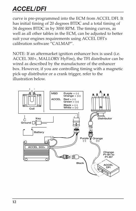
ACCEL/DFIcurve is pre-programmed into the ECM from ACCEL DFI. Ithas initial timing of 20 degrees BTDC and a total timing of34 degrees BTDC in by 3000 RPM. The timing curves, aswell as all other tables in the ECM, can be adjusted to bettersuit your engines requirements using ACCEL DFI’scalibration software “CALMAP”.
NOTE: If an aftermarket ignition enhancer box is used (i.e.ACCEL 300+, MALLORY HyFire), the TFI distributor can bewired as described by the manufacturer of the enhancerbox. However, if you are controlling timing with a magneticpick-up distributor or a crank trigger, refer to theillustration below.
Distributor
Coil
-+
ACCEL 300+
Key
Battery
Ground
ACCELDFI
Orange(+)
Purple(-)
Black
MSD Purple = (-)Orange = (+)
ACCEL Red = (-)Green = (+)Black = (-)White = (+)
ChangeP1-B1 toP1-B7

13
ACCEL/DFIVII. FUEL PUMP MOUNTING
AND HIGH PRESSURE LINE INSTALLATION
ACCEL DFI currently has two high pressure fuel pumpsavailable: part number 74701, an external mount fuel pumpwhich can support up to 450 horsepower @ 45 PSI, and partnumber 74702 which can support up to 840 horsepower @45 PSI. This fuel pump can be mounted in the fuel tank oron the frame rail. You can use part number 74710 to mountthis pump onto your frame rail. Regardless of the fuelpump used, be sure to mount your fuel pump near the tankat a point of fuel level and in a protected area. Systemcomponents must also be protected and shielded fromexhaust and engine compartment heat as well as frompotential road damage.
FUEL PUMP WIRING
The fuel pump requires a +12 volt source. If your vehiclewas originally an EFI vehicle and already has a fuel pumpinstalled, you still MUST use the ACCEL DFI wiring.Connect the +12 VDC side of the fuel pump to the ACCELDFI main wiring harness, using the red wire with whitetracer. The fuel pump relay is already an integral part of themain wiring harness and is controlled by the ECM, thereforeno wiring is necessary for the relay. A pump will drawbetween 4 and 8 amps of current depending on size andfuel system pressure, so 14 gauge wire should be used fromthe pump to the red wire with white tracer. Also, be sure tosolder the connection between these two wires. The groundfor the fuel pump can be at any clean, paint-free point onthe chassis to the negative (-) terminal of the fuel pump.Make sure that wiring between the fuel pump and theengine compartment does not hang below the vehicle, interferewith rotating parts, or become exposed to excess heat.

14
ACCEL/DFIMECHANICAL PUMP REMOVAL
If your engine was carbureted, be sure to either cap off thefittings on your mechanical pump or remove the pump andcover the opening with a block off plate.
HIGH PRESSURE FUEL FILTER MOUNTING
Locate the high pressure fuel filter at the outlet of the highpressure fuel pump on the frame rail. It is recommended toplace a filter between the fuel tank outlet and the pumpinlet if the pickup tube in the tank does not have a filter.Failure to do so can result in fuel pump damage. ACCELDFI high pressure filter, part number 74720 requires 3/8”Saginaw fittings. If your filter does not have these fittingsyou can use part number 74721, these adapter fittings willfit the 74720 filter and allow you to use a 6AN fitting.
ROUTING HIGH PRESSURE FUEL HOSE
At this point the high pressure circuit of the fuel system canbe plumbed (refer to diagram at the end of this section). Ifthe existing fuel supply line cannot sustain 150 PSI fuelpressure (ACCEL recommends a fuel line rated to at least330 PSI), then it must be replaced with high pressure fuelline/tubing. Remember, with a carburetor, your fuel systemoperated at about 6 PSI. However, with fuel injection, thesystem operates around 50 PSI of fuel pressure. Never takeany chances. If in doubt, replace the hose. You will need aminimum of 3/8” ID supply line and 5/16” ID return.


16
ACCEL/DFIDUAL FUEL TANKS
It is important to note that for vehicles with two fuel tanksand/or a class “A” RV, it is highly recommended that aboost pump be installed in each tank and feed though amulti-port switching valve, especially when operating inhot climates. Boost pumps used on such vehicles as a 1985Ford F-250 5.0L EFI will work well for this type of applica-tion. The switching valve from a 1984 Ford Diesel or a 1986Chevrolet C-10 (305 CID) will work well in dual tank appli-cations. Dual tank equipped vehicles must be plumbed toreturn excess fuel to the tank which is supplying fuel to theEFI system to avoid tank overflow problems. The remotely-activated dual tank three-way valves described above willwork well in these applications.
A NOTE TO THE INSTALLER
There seems to be a misunderstanding with some peoplethat a fuel pump “produces pressure”. This is not accurate.What actually happens is the pump produces fuel flow at agiven system pressure which is dictated by the pressureregulator. The pressure regulator has a spring which ispreset to provide a certain system pressure, i.e. 45 PSI. Theregulator opens as the pressure in the fuel line increasesdue to the flow of fuel provided by the pump.
As the pressure drops, due to bypassing of fuel to the tank,the regulator closes at a pressure of 45 PSI (this pressure isvariable on adjustable regulators). This process will beginagain as pressure raises. Therefore, the pressure regulator isa dynamic modulating device which always tries to seek itspreset pressure.

17
ACCEL/DFISENDING UNIT MODIFICATIONS
To install a return line in your tank, remove the senderassembly from the fuel tank and drill a 5/16” hole throughthe top of the flange. Be sure to give yourself enough roomto weld the tube into place, welding procedures arediscussed later in this section. ACCEL DFI jumper line kit,part number 74731, will supply you with this line as well asother lines that you may need. Pre-bend a piece of 5/16”fuel line so that the in-tank portion end is 2” from thebottom of the tank and away from existing outlet tubes (Seefigure at the end of this section). Ensure that the installationof this tube does not interfere with any other componentson the tank unit. Clean the unit with soap and water priorto the next step. Seal and secure the return line to the flangeby welding or brazing with low heat so that flange warpagedoes not occur. Also make sure that applied heat does notdamage the sending unit wires or wire seals. Clean thewelded area and check for cracks or holes in the flange,tubes or welded area.
Check the condition of the filter sock on the pick-up tube.If the sock is torn or contaminated, replace it. Again, if youare not using a filter sock in your application then install afilter between the fuel tank supply line and the inlet side ofyour fuel pump.

18
ACCEL/DFI
RETURN FUEL LINE INSTALLATION
If your vehicle was originally equipped with a carburetor,you MUST run a 5/16” ID (inner diameter) or larger returnline from the engine (fuel pressure regulator) to the fueltank. Some vehicles with carburetors came with 1/4”diameter return lines. This is too small in ID (innerdiameter) and will create an unacceptable amount of backpressure in the fuel line, thus causing a rich condition.Using good judgment install a fuel line from the pressureregulator outlet to the fuel tank with restriction free bendsin protected areas (refer to the diagram at the end of the“Routing High Pressure Fuel Hose” section). The fitting at
5/16 Fuel Return Line Must BeAdded to Non-Fuel InjectedVehicles. See InstallationManual for Proper InstallationBraze Tube to Flangemaking Sure Not toMelt any Rubber orPlastic Components
Existing Wire Harness
High Pressure Feed
Vapor VentEmissions/Canister
Top of Tank
Bottom of Tank
Return Line
2"


20
ACCEL/DFI
IX. AIR CLEANER ASSEMBLY
If you are using a stock throttle body on your application,the ACCEL POWERFILTER division of ACCEL may verywell have a high performance reusable air cleaner for you.They may also have one for your custom application, contactACCEL’s Technical support team for more information.
At this point all the electrical connections should be madebetween the sensors, computer, and optional equipment.Keep in mind that you will have at least one extra connectorthat will not be used on the main wiring harness. Nowconnect the positive terminal to the positive side of thebattery, and the ground wires to the negative batteryterminal (refer to the diagram in section V).
X. STARTING THE VEHICLE
Turn the ignition key to the run position. Do not crank yet.The fuel pump should run for two seconds, then shut off.Now turn the ignition key off. Repeat this procedure ofturning the key on and off four times, listening carefully forthe fuel pump. This is needed to prime the fuel deliverysystem. The best way to check if the system is priming is toconnect a fuel pressure gauge to the shroeder valve on thefuel rail. ACCEL DFI offers gauges for some Fordapplications, check your application with one of ACCEL’sdealers. Now check for leaks along the entire length of thevehicle. Crank the engine. After the engine starts, the engineshould fast idle and the speed will decrease as the coolanttemperature heats up. If the engine does not start after tenseconds of cranking, check the following:

21
ACCEL/DFIA) All electrical and mechanical connections are made
securely.B) There are no fuel leaks. C) The fuel feed line is pressurized with fuel. The most
common problem is the fuel pump is wired backward. On the ACCEL pumps, the positive (+) and negative (-) designations are casted in the pump adjacent to theterminals. If the ACCEL 74702 pump is wiredbackwards, it will run backwards.
D) Ensure that the engine timing is properly set.
XI. OPTIONAL ITEMS
(1) User Interface Module (UIM, part number 74500)
This option allows the driver to change the threedimensional fuel table while the engine is running. TheUIM contains two potentiometers for increasing ordecreasing the amount of fuel supplied to the engine duringidle and WOT. The idle potentiometer provides the userwith the ability to increase or decrease the amount of fuel atidle and part throttle by 10%. The WOT potentiometercomes into play only when the throttle is fully opened. Thepercent increase and decrease is 25%. The UIM does notchange the amount of fuel delivered during cranking.
The UIM must remain connected to the main wiringharness after adjustments are made to the ECM. If it isdisconnected, the ECM will automatically default back toits preset values.
If your engine requires a somewhat different calibrationthan is noted on the ECM or you are calibrating a uniqueengine combination, use the ACCEL DFI Serial

22
ACCEL/DFI
Communications Interface option, CALMAP (part number74990-S with a 5ft cable, 74990-L with a 25ft cable). Thissoftware will allow you to customize the Fuel and Timingcurves as well as all other parameters in the ECM.
FAN CONTROL KIT (PART NUMBER 74171)
This kit includes a harness with a integral relay thatinterfaces between the ECM and the fan. This allows youto turn on an electric fan at a given engine temperature viaCALMAP. This kit does not include a fan.
NITROUS OXIDE CONTROL (part numbers listed below)
Single Stage Harness OnlyPart Number 74253
Multi-Stage Harness OnlyPart Number 74697
Although ACCEL DFI currently does not have completenitrous oxide kits available for Ford applications, we dooffer the necessary wiring to allow you to control yournitrous through the ACCEL DFI ECM. The part numberslisted above are ready to plug into your ACCEL DFI ECMand nitrous solenoid to give you exact delay control,ignition timing and fuel control over your nitrous system.ACCEL can also offer you the nitrous solenoid, contact yourlocal ACCEL EMIC dealer for more information.

23
ACCEL/DFI
XII. TROUBLE SHOOTING GUIDE
The following are some common problems we haveencountered with various installations.
Injectors not firing (clicking) - the vehicle will not start:• Usually due to a low battery. Voltage must be above nine
(9) volts during cranking to activate the ECM.• Injector harness not connected to the main wiring harness.• Short in either pin P1-C7 or P1-C8. Check continuity to
battery positive (+) and negative (-) wires with an OHMmeter.
• Tach wires to positive (+) side of coil instead of negative (-).• P1-D7 (long pink wire with female spade connector) not
receiving +12 volts during cranking. Usually due toconnecting this wire to a voltage source that is disabledduring cranking.
Runs rich at idle:• Vacuum line to fuel pressure regulator not connected.• MAP sensor vacuum line pinched.• UIM idle knob turned all one way.• Wrong injectors for the application.• Return fuel line is too small/restricted.• Calibration in the ECM is wrong for the application.
Runs rich all the time:• Wrong injectors for the application• Return line is too small/restricted.• Calibration in the ECM is wrong for the application.
Engine cranks a while before starting:• +12V and ground terminals not connected directly to battery.• Fuel pump is not priming the fuel system.
If you are experiencing problems please contact your ACCELdealer, of feel free to call ACCEL’s technical service line and talkto an ACCEL DFI technical representative at 1.216.398.8300 ext. 5.

The Mr. Gasket Performance GroupCleveland, Ohio
216.398.8300www.mrgasket.com
Printed in U.S.A. INST0097A 3-99


![Accel World/Accel World /Accel World... · Accel World [5] Al costado de un polvoriento pasillo se encontraba el baño de hombres, el santuario privado y oculto de Haruyuki. Entró](https://static.fdocuments.net/doc/165x107/61189c9ec6d1da0eea7f2dc9/accel-world-accel-world-accel-world-accel-world-5-al-costado-de-un-polvoriento.jpg)