INSTALLATION AND LAUNCH - BelSimTek · PDF fileDCS: MIG-15bis INSTALLATION AND LAUNCH 2 Game...
32
i
-
Upload
truonghanh -
Category
Documents
-
view
217 -
download
0
Transcript of INSTALLATION AND LAUNCH - BelSimTek · PDF fileDCS: MIG-15bis INSTALLATION AND LAUNCH 2 Game...
i

DCS: MIG-15bis HEALTH WARNING
HEALTH WARNING!
Please read before using this computer game or allowing your children to use it.
A very small proportion of people may experience a seizure or loss of consciousness when exposed to certain visual images, including flashing lights or light patterns that can occur in computer games. This may happen even with people who have no medical history of seizures, epilepsy, or “photosensitive epileptic seizures” while playing computer games.
These seizures have a variety of symptoms, including light-headedness, dizziness, disorientation, blurred vision, eye or face twitching, loss of consciousness or awareness even if momentarily.
Immediately stop playing and consult your doctor if you or your children experience any of the above symptoms.
The risk of seizures can be reduced if the following precautions are taken, (as well as a general health advice for playing computer games):
Do not play when you are drowsy or tired.
Play in a well-lit room.
Rest for at least 10 minutes per hour when playing the computer game.
DCS: MIG-15bis INSTALLATION AND LAUNCH
1
INSTALLATION AND LAUNCH
Place the Setup.exe file and all .bin files in the same folder and double click on the Setup.exe file to begin installation. Then follow the on-screen instructions.
Note: You will need to be logged into Windows with Administrator rights in order to install the game.
Launching DCS: MiG-15bis
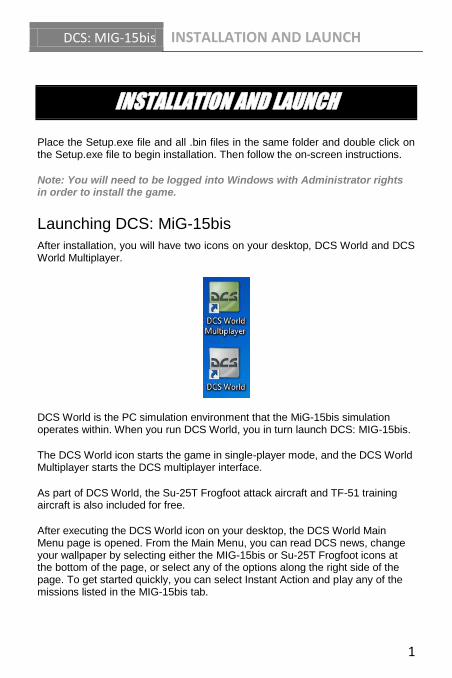
After installation, you will have two icons on your desktop, DCS World and DCS World Multiplayer.
DCS World is the PC simulation environment that the MiG-15bis simulation operates within. When you run DCS World, you in turn launch DCS: MIG-15bis.
The DCS World icon starts the game in single-player mode, and the DCS World Multiplayer starts the DCS multiplayer interface.
As part of DCS World, the Su-25T Frogfoot attack aircraft and TF-51 training aircraft is also included for free.
After executing the DCS World icon on your desktop, the DCS World Main Menu page is opened. From the Main Menu, you can read DCS news, change your wallpaper by selecting either the MIG-15bis or Su-25T Frogfoot icons at the bottom of the page, or select any of the options along the right side of the page. To get started quickly, you can select Instant Action and play any of the missions listed in the MIG-15bis tab.

DCS: MIG-15bis INSTALLATION AND LAUNCH
2
Game Problems
If you encounter a problem, particularly with controls, we suggest you back up and then delete your Saved Games\User Name\DCS\Config folder, which is created by DCS on your operating system drive at first launch. Restart the game and this folder will be rebuilt automatically with default settings, including all of the controller input profiles.
If problems persist, we suggest consulting our online technical support forums at http://forums.eagle.ru/forumdisplay.php?f=251
Game Manuals
The Activation Guide describing serial key activation/deactivation is available in the /Doc folder of the game’s root installation directory.
Additional documentation for DCS: MIG-15bis, including the complete Flight Manual and a key commands guide can be found in the \Mods\aircraft\MIG-15bis\Doc folder of the game installation directory.
Useful Links
DCS Homepage:
http://www.digitalcombatsimulator.com/
DCS: MIG-15bis forum:
http://forums.eagle.ru/forumdisplay.php?f=383
DCS Wiki:
http://en.wiki.eagle.ru/wiki/Main_Page
DCS: MIG-15bis FLIGHT CONTROL
3
FLIGHT CONTROL
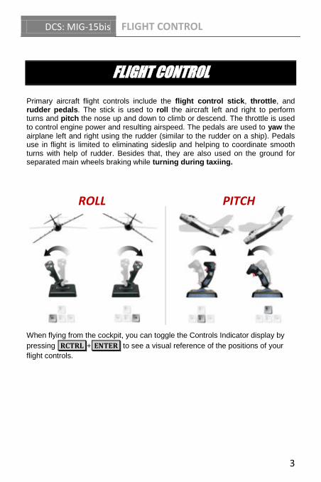
Primary aircraft flight controls include the flight control stick, throttle, and rudder pedals. The stick is used to roll the aircraft left and right to perform turns and pitch the nose up and down to climb or descend. The throttle is used to control engine power and resulting airspeed. The pedals are used to yaw the airplane left and right using the rudder (similar to the rudder on a ship). Pedals use in flight is limited to eliminating sideslip and helping to coordinate smooth turns with help of rudder. Besides that, they are also used on the ground for separated main wheels braking while turning during taxiing.
When flying from the cockpit, you can toggle the Controls Indicator display by
pressing RCTRL + ENTER to see a visual reference of the positions of your
flight controls.
ROLL PITCH
DCS: MIG-15bis FLIGHT CONTROL
4
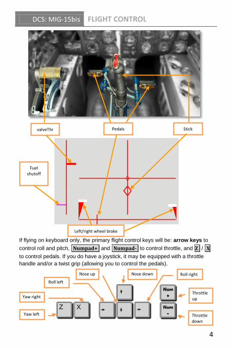
If flying on keyboard only, the primary flight control keys will be: arrow keys to
control roll and pitch, Numpad+ and Numpad- to control throttle, and Z / X
to control pedals. If you do have a joystick, it may be equipped with a throttle
handle and/or a twist grip (allowing you to control the pedals).
Yaw left
Roll left
Roll right
Throttle down
Yaw right Throttle up
Nose down
Nose up
valveThrottle
Pedals Stick
Fuel shutoff
Left/right wheel brake

DCS: MIG-15bis COCKPIT
5
COCKPIT
The MIG-15bis features a conventional cockpit layout. The flight controls are conventional, with a centrally mounted control stick, left-handed throttle handle, and foot-operated rudder pedals. The forward cockpit is dominated by the instrument panel and the ASP-3N gunsight positioned above it. The side panels house various aircraft system controls and indicators.
1. Left main gear emergency release
handle
2. Instrument panel
3. KI-11 liquid compass
4. ASP-3N gunsight
5. Armament control panel
6. Canopy closing handle
7. Right main gear and nose gear
emergency release handle
8. Canopy opening handle
9. Right side console
10. Right rudder pedal
11. Control stick
12. Left rudder pedal
13. Aileron hydraulic booster control
handle
14. Flaps control handle
15. Throttle
16. Left side console
DCS: MIG-15bis COCKPIT
6
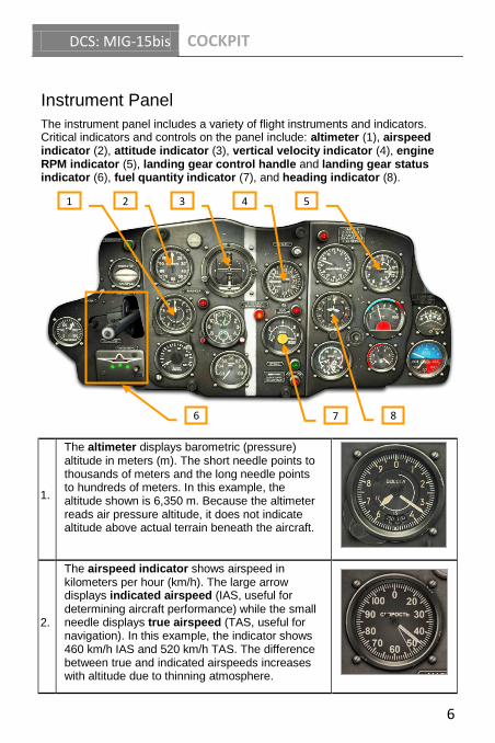
Instrument Panel
The instrument panel includes a variety of flight instruments and indicators. Critical indicators and controls on the panel include: altimeter (1), airspeed indicator (2), attitude indicator (3), vertical velocity indicator (4), engine RPM indicator (5), landing gear control handle and landing gear status indicator (6), fuel quantity indicator (7), and heading indicator (8).
1.
The altimeter displays barometric (pressure) altitude in meters (m). The short needle points to thousands of meters and the long needle points to hundreds of meters. In this example, the altitude shown is 6,350 m. Because the altimeter reads air pressure altitude, it does not indicate altitude above actual terrain beneath the aircraft.
2.
The airspeed indicator shows airspeed in kilometers per hour (km/h). The large arrow displays indicated airspeed (IAS, useful for determining aircraft performance) while the small needle displays true airspeed (TAS, useful for navigation). In this example, the indicator shows 460 km/h IAS and 520 km/h TAS. The difference between true and indicated airspeeds increases with altitude due to thinning atmosphere.
2 3 4 5
6 7 8
1

DCS: MIG-15bis COCKPIT
7
3.
The attitude indicator shows the aircraft’s pitch and roll position relative to the horizon. In this example, the aircraft symbol indicates 20° of nose up pitch and 30° of right roll. The indicator also includes a slip ball inside a glass tube to display sideslip and a turn indicator along the bottom of the pitch scale to display turn rate and direction.
4.
The vertical velocity indicator shows rate of climb/descent in meters per second (m/s). This indicator is especially useful to help maintain level flight and safe descent rates when landing (no more than 10 m/s). In this example, the indicator shows a descent rate of 10 m/s.
5.
The engine RPM indicator displays engine compressor revolutions per minute (RPM) and is the main gauge of engine power output. Engine RPM is controlled by the throttle. The inside scale displays 0 - 5,000 RPM (used when starting the engine and at low power settings) while the outside scale displays 5,000 - 15,000 RPM (typical in flight).
6.
The landing gear control handle is used to raise and lower the landing gear. This can be done either by mouse-clicking over the handle or
pressing G . The handle features a locking
mechanism, which can be used to lock the handle in the middle position to prevent it from moving up or down and maintain the landing gear in the
current position LALT + G .
The landing gear status indicator displays the state of the main and nose gears: three green for down and locked or three red for raised and locked. The lights are off when the gear is in transition or not safely locked.
DCS: MIG-15bis COCKPIT
8
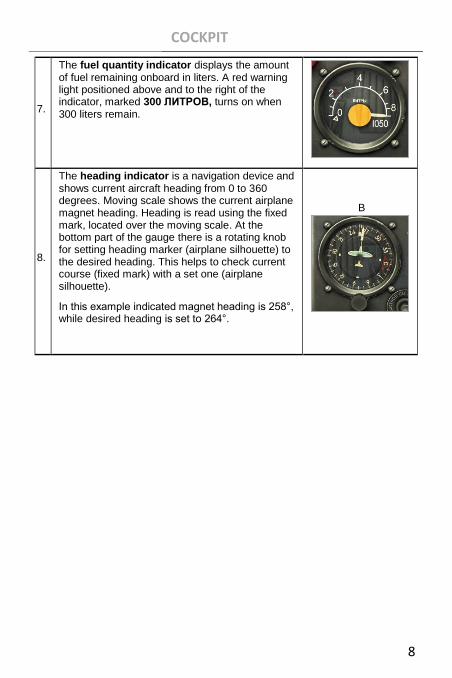
7.
The fuel quantity indicator displays the amount of fuel remaining onboard in liters. A red warning light positioned above and to the right of the indicator, marked 300 ЛИТРОВ, turns on when 300 liters remain.
8.
The heading indicator is a navigation device and shows current aircraft heading from 0 to 360 degrees. Moving scale shows the current airplane magnet heading. Heading is read using the fixed mark, located over the moving scale. At the bottom part of the gauge there is a rotating knob for setting heading marker (airplane silhouette) to the desired heading. This helps to check current course (fixed mark) with a set one (airplane silhouette).
In this example indicated magnet heading is 258°, while desired heading is set to 264°.
B

DCS: MIG-15bis PROCEDURES
9
PROCEDURES
Cold Start
The automatic start-up procedure can be activated by pressing L.WIN + HOME .
Automatic shut down can be activated by pressing L.WIN + END .
1. Request electrical power by contacting the ground crew:
F11 → F8 → F2 → F1
1. Before engine start-up set automatic circuit breakers on the
right electrical panel to the following positions:
Note: For a better view on the right or the left electrical panels player can press
and keep pressed keyboard combinations 0 + 3 or 0 + 1 on the numeric
keyboard.
АККУМ. (battery) switch - OFF (aft)
ГЕНЕР. (generator) switch - ON (forward)
Request ground electrical power:
o Open radio menu - \ .
o Select ground crew - F8 .
o Select electrical power - F2 .
o Request electrical power ON - F1
Check the landing gear status indicator lights to turn on (three
green) to confirm electrical power is running
Turn on all of the remaining switches on the right switch panel to
enable aircraft flight and armament systems (except АККУМ.)
Generator switch
Battery switch
DCS: MIG-15bis PROCEDURES
10
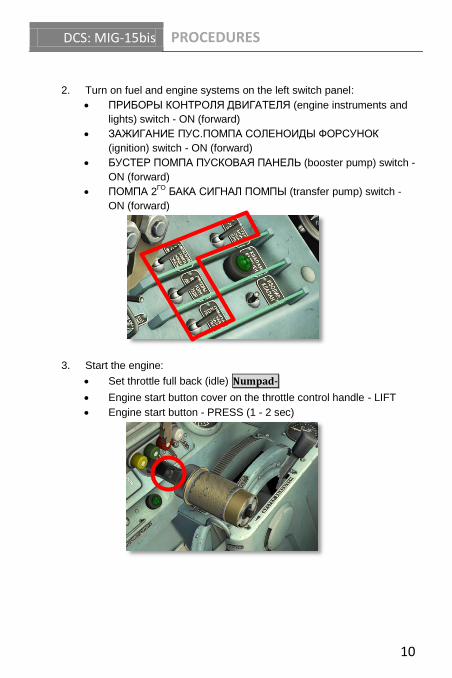
2. Turn on fuel and engine systems on the left switch panel:
ПРИБОРЫ КОНТРОЛЯ ДВИГАТЕЛЯ (engine instruments and
lights) switch - ON (forward)
ЗАЖИГАНИЕ ПУС.ПОМПА СОЛЕНОИДЫ ФОРСУНОК
(ignition) switch - ON (forward)
БУСТЕР ПОМПА ПУСКОВАЯ ПАНЕЛЬ (booster pump) switch -
ON (forward)
ПОМПА 2ГО
БАКА СИГНАЛ ПОМПЫ (transfer pump) switch -
ON (forward)
3. Start the engine:
Set throttle full back (idle) Numpad-
Engine start button cover on the throttle control handle - LIFT
Engine start button - PRESS (1 - 2 sec)

DCS: MIG-15bis PROCEDURES
11
Open the fuel shutoff valve (left of the pilot seat) to 50% HOME (one
press) when engine reaches 600 RPM (cranking from the electrical
starter)
As engine reaches 900 - 1200 RPM, press and hold R. SHIFT + HOME to
move the fuel shutoff lever to the fully open position (down)
Check engine idle speed to stabilize at 2400 - 2600 RPM and
exhaust gas temperature (EGT) no greater than 650°C
Increase engine power Numpad+ to set 5000 RPM
Check ГЕНЕРАТОР ВЫКЛЮЧЕН (generator off) light to
extinguish as RPM passes 4500 indicating normal operation of
the generator
4. Complete aircraft start
Contact the ground crew to disconnect ground electrical power
F11 → F8 → F2 → F2
АККУМ. (battery) switch - ON (forward)
Close the canopy L.CTRL + C
5000 RPM
GENERATOR OFF light extinguished
EGT

DCS: MIG-15bis PROCEDURES
12
Pressurize the cockpit by turning the pressurization valve until the pointing index moves past the grey mark (to "Х" (blue) - cold air; "Т" (yellow) - warm air, or "Г" (red) - hot air)
Turn on the pilot's oxygen supply by opening the oxygen supply valve
Taxi
1. Before taxiing it is necessary to prepare landing gear for retraction after
takeoff.
Mouse click over the landing gear control handle
locking mechanism or press L.ALT + G to unlock
the landing gear control handle in preparation for
takeoff
2. Press L. SHIFT + F once to lower the flaps to the
20° takeoff setting
3. Press Numpad+ / Numpad- to manage engine
power. Increase engine power to approximately 6000 RPM to begin moving forward, then reduce RPM back down to maintain a slow taxi speed
Pilot oxygen supply valve (left cockpit side)
Pressurization control valve (right cockpit side)
20° down flaps position
Landing gear lever unlocked
DCS: MIG-15bis PROCEDURES
13
4. Test and apply the wheel brakes as needed W
5. To turn while taxing on the ground, apply rudder pedal input in the desired
direction of turn Z / X while simultaneously applying the wheel brakes W .
For example to turn right, press and hold X to apply right pedal while
pressing W to apply the wheel brakes
6. While taxiing, set the engine RPM to the level, which provides safe taxiing speed.
DCS: MIG-15bis PROCEDURES
14
Takeoff
1. Enter the runway and line up airplane along the centerline (do not try to align
airplane on the centerline precisely, any alignment parallel to the centerline is
good enough).
2. Increase engine revolutions to 8000-9000 RPM Numpad+ , release brakes.
When airplane starts takeoff rolling increase throttle to the maximum value
(takeoff value).
3. In the initial roll maintain direction by breaking separately the main landing
gear wheels with pedal inputs Z / X while simultaneously pressing the
wheel brakes W . After reaching 50 - 80 km/h, rudder became efficient and
direction is held by pedals only, without applying the wheel brakes.
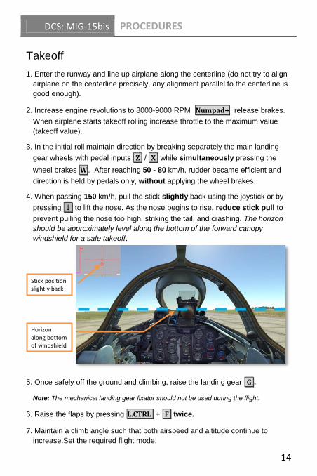
4. When passing 150 km/h, pull the stick slightly back using the joystick or by
pressing ↓ to lift the nose. As the nose begins to rise, reduce stick pull to
prevent pulling the nose too high, striking the tail, and crashing. The horizon
should be approximately level along the bottom of the forward canopy
windshield for a safe takeoff.
5. Once safely off the ground and climbing, raise the landing gear G .
Note: The mechanical landing gear fixator should not be used during the flight.
6. Raise the flaps by pressing L.CTRL + F twice.
7. Maintain a climb angle such that both airspeed and altitude continue to
increase.Set the required flight mode.
Stick position slightly back
Horizon along bottom of windshield glass

DCS: MIG-15bis PROCEDURES
15

DCS: MIG-15bis PROCEDURES
16
Landing
1. Before entering final approach, decrease engine
power Numpad- and use the airbrake by holding
down B to reduce airspeed to approximately 400 -
450 km/h. To keep the airbrake open without having to hold down the airbrake button, use the airbrake switch on the left side of the cockpit. Set the switch
forward to open the airbrake L.SHIFT + B or aft
to close it L.CNTRL + B
2. Press G to lower the landing gear.
While flying without descending, retract airbrakes and increase engine RPM to avoid speed loss.
3. Continue to reduce airspeed to 320 - 350 km/h. Press L.SHIFT + F twice
to set flaps to 20°, then after at least 1 second (required to unlock the actuators), press the command a third time to set flaps to the landing position of 55°.
4. Final approach speed is 250 - 270 km/h. As you approach, continue to reduce airspeed toward the desired touchdown speed of 200 - 220 km/h. Engine power on final approach is approximately 7000 - 9000 RPM. Avoid reducing engine power below 6000 RPM. Speeds below 200 km/h may lead to a stall, loss of control, and crash.
On final approach, the stowed mechanical reticle of the gunsight can act as a helpful reference by placing it over the runway threshold. In other words, "aim" for the touchdown point by placing the threshold along the bottom of the gunsight glass.
55° down flaps position
Airbrake switch
DCS: MIG-15bis PROCEDURES
17
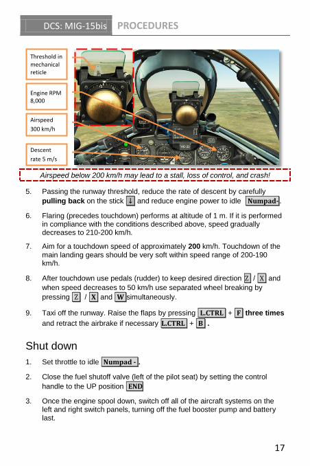
Airspeed below 200 km/h may lead to a stall, loss of control, and crash!
5. Passing the runway threshold, reduce the rate of descent by carefully
pulling back on the stick ↓ and reduce engine power to idle .Numpad- .
6. Flaring (precedes touchdown) performs at altitude of 1 m. If it is performed in compliance with the conditions described above, speed gradually decreases to 210-200 km/h.
7. Aim for a touchdown speed of approximately 200 km/h. Touchdown of the main landing gears should be very soft within speed range of 200-190 km/h.
8. After touchdown use pedals (rudder) to keep desired direction Z / X and
when speed decreases to 50 km/h use separated wheel breaking by
pressing Z / X and W simultaneously.
9. Taxi off the runway. Raise the flaps by pressing L.CTRL + F three times
and retract the airbrake if necessary L.CTRL + B .
Shut down
1. Set throttle to idle Numpad - .
2. Close the fuel shutoff valve (left of the pilot seat) by setting the control
handle to the UP position END
3. Once the engine spool down, switch off all of the aircraft systems on the left and right switch panels, turning off the fuel booster pump and battery last.
Engine RPM 8,000
Threshold in mechanical reticle
Airspeed 300 km/h
Descent
rate 5 m/s

DCS: MIG-15bis WEAPONS EMPLOYMENT
18
WEAPONS EMPLOYMENT
MIG-15bis armament consists of:
2 x 23 mm NR-23 cannon with 80 rounds each
1 x 37 mm N-37D cannon with 40 rounds
2 x FAB-100 or FAB-50 free falling bombs
Two 300 liter, 400 liter, or 600 liter external fuel tanks can be carried in place of bombs.
ASP-3N Gunsight
Gun aiming is accomplished using the ASP-3N gunsight. The sight features a complex system of gyroscopes to provide a calculated aiming point. In order to achieve an accurate firing solution, the pilot must manually dial in the correct wingspan of the target and continually adjust the target range using the throttle twist grip.
Because the gyro system suffers calculation errors under heavy maneuvering, the sight can be set to fixed (caged) reticle mode when used during heavy maneuvering, at very short ranges, or for snapshot fire.
The gunsight must be caged at all times other than active target engagement to avoid building errors or damaging the gyro mechanisms!

DCS: MIG-15bis WEAPONS EMPLOYMENT
19
1. Reflector glass 2. Sun filter glass 3. Standby mechanical reticle 4. Target wingspan dial
5. Reticle brightness knob 6. Caging lever (down for caged
mode, up for gyro mode)
Armament Control Panel
The armament control panel is located below the instrument panel. This panel includes a number of important indicators and controls for configuring weapons for fire.
Gun ready lights
Bombs arming switch
Bombs armed light
Bombs loaded lights
DCS: MIG-15bis WEAPONS EMPLOYMENT
20
Gun ready lights. From left to right, each red light indicates the readiness of the left 23 mm, right 23 mm, and 37 mm cannon for fire, respectively.
Bombs arming switch. Used to set bombs for armed release.
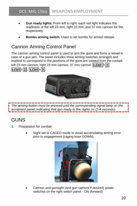
Cannon Arming Control Panel
The cannon arming control panel is used to arm the guns and force a reload in case of a gun jam. The panel includes three arming switches arranged and marked to correspond to the positions of the guns are viewed from the cockpit:
left 23 mm cannon, right 23 mm cannon, 37 mm cannon L.Ctrl + 1 ,
L.Ctrl + 2 , L.Ctrl + 3 .
The arming button must be pressed until the corresponding signal lamp on the armament panel, indicating that gun ready to fire, lights on (2-4 seconds).
GUNS
1. Preparation for combat:
Sight set to CAGED mode to avoid accumulating aiming error prior to engagement (caging lever DOWN)
Cannon and gunsight (and gun camera if desired) power switches on the right switch panel - ON (forward)
DCS: MIG-15bis WEAPONS EMPLOYMENT
21
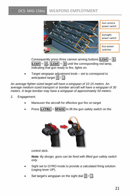
Consequently press three cannon arming buttons L.Ctrl + 1 ,
L.Ctrl + 2 , L.Ctrl + 3 until the corresponding red lamp,
indicating that gun ready to fire, lights on.
Target wingspan adjustment knob – set to correspond to
anticipated target / / , .
An average fighter-sized target will have a wingspan of 10-15 meters. An average medium-sized transport or bomber aircraft will have a wingspan of 30 meters. A large bomber may have a wingspan of approximately 50 meters.
2. Engagement:
Maneuver the aircraft for effective gun fire on target
Press L.CTRL + SPACE to lift the gun safety switch on the
control stick.
Note: By design, guns can be fired with lifted gun safety switch only.
Sight set to GYRO mode to provide a calculated firing solution (caging lever UP).
Set target’s wingspan on the sight dial / / , .
Gun camera power switch
Gun power switches
Gunsight power switch

DCS: MIG-15bis WEAPONS EMPLOYMENT
22
Continually adjust the throttle twist grip as required to "frame" the target's wingspan inside the sight reticle diamonds to enter
correct range data into the sight . / ; .
Press SPACE to fire the 23 mm cannon or R.CTRL + SPACE to
fire the 37 mm cannon.
Guns armed Gun safety OFF
Target 's wings framed by diamond reticle
Target 's wingspan set on sight dial
Sight set to GYRO mode (lever UP)
DCS: MIG-15bis WEAPONS EMPLOYMENT
23
Once the engagement is complete, press L.CTRL + SPACE to
close the gun safety switch on the control stick and set the sight to CAGED mode (caging lever DOWN).
Bombs
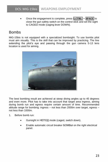
MiG-15bis is not equipped with a specialized bombsight. To use bombs pilot must aim visually. This is the skill that can be improved by practicing. The line extending the pilot’s eye and passing through the gun camera S-13 lens location is used for aiming.
The best bombing result are achieved at steep diving angles up to 45 degrees and even more. Pilot has to take into account that target area ingress, aiming during bomb run and egress require certain amount of time. Recommended altitude range for bombing: ingress – not less than 2000m over target, egress – not less than 1000m.
1. Before bomb run:
Gunsight in НЕПОД mode (caged, switch down).
Enable automatic circuit breaker БОМБЫ on the right electrical panel.

DCS: MIG-15bis WEAPONS EMPLOYMENT
24
ТАКТИЧЕСКИЙ СБРОС ВКЛЮЧЁН НА ВЗРЫВ switch has to be set to the upper position. The bombs armed lamp and two green lamps, indicating that bombs are on pylons, light on.
2. Aiming during bombing:
Bombs power switch
Bombs armed
Bombs are on pylons Наличие бомб
Altitude 2000 m
Dive angle -40°
DCS: MIG-15bis WEAPONS EMPLOYMENT
25
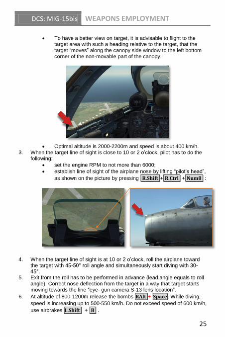
To have a better view on target, it is advisable to flight to the target area with such a heading relative to the target, that the target “moves” along the canopy side window to the left bottom corner of the non-movable part of the canopy.
Optimal altitude is 2000-2200m and speed is about 400 km/h. 3. When the target line of sight is close to 10 or 2 o’clock, pilot has to do the
following:
set the engine RPM to not more than 6000;
establish line of sight of the airplane nose by lifting “pilot’s head”,
as shown on the picture by pressing R.Shift + R.Ctrl + Num8 :
4. When the target line of sight is at 10 or 2 o’clock, roll the airplane toward the target with 45-50° roll angle and simultaneously start diving with 30-45°.
5. Exit from the roll has to be performed in advance (lead angle equals to roll angle). Correct nose deflection from the target in a way that target starts moving towards the line “eye- gun camera S-13 lens location”.
6. At altitude of 800-1200m release the bombs RAlt + Space . While diving,
speed is increasing up to 500-550 km/h. Do not exceed speed of 600 km/h,
use airbrakes L.Shift + B .
DCS: MIG-15bis WEAPONS EMPLOYMENT
26
7. Retract airbrake while egressing from bombing run.
To have a consistent result practicing is required. It is nice to know that:
increased speed while releasing bombs leads to increased bombs overfly (projection of the trajectory of the falling bomb on the horizontal surface);
reduction of diving angle leads to bombs overfly;
increasing of bombs release altitude with the same diving angle leads to bomb under fly.

DCS: MIG-15bis WEAPONS EMPLOYMENT
27

DCS: MIG-15bis WEAPONS EMPLOYMENT
28

DCS: MIG-15bis WEAPONS EMPLOYMENT
29

30