INST OF TECH OCEAN ENGINEERIN. R MI UNCLASSIFIED …
121
STRENGTH LOUl ALLOY STEELS .(U) MASSACHULSETTS INST OF TECH CANBIDGE DEPT OF OCEAN ENGINEERIN. R MI JUN 87 UNCLASSIFIED N88228-85-G-3262 F/G 11/6 1M I llllmmllllll, llllollollllml lllllmllllmllI ElllEEEEEEEEEEE
Transcript of INST OF TECH OCEAN ENGINEERIN. R MI UNCLASSIFIED …

STRENGTH LOUl ALLOY STEELS .(U) MASSACHULSETTS INST OFTECH CANBIDGE DEPT OF OCEAN ENGINEERIN. R MI JUN 87
UNCLASSIFIED N88228-85-G-3262 F/G 11/6 1M
I llllmmllllll,llllollollllmllllllmllllmllIElllEEEEEEEEEEE

% 4
I __ - 40II,'' I- mn IL.L
II1IIN Il- 'IIllIllhI ~ 1.8
12 111114 111.6
MICROCOPY RESOLUTION TIST CHART
m %
% % %

Ln DEPARTMENT OF OCEAN ENGINEERING CMASSACHUSETTS INSTITUTE OF TECHNOLOGY
CAMBRIDGE, MASSACHUSETTS 02139
CR\ );G TENDANCTES OF RESTRAINED 'ELDS jN EI( 5
STR.ENGTH LO' ALLOY STEELS UNDER HYPEBARiCI: I OND IT IONS
bv RANDOLPH NI
OCE:A N ENGINEERING COURSE \IIIAMECHANICAL ENGINEERING COURSE II JAN 2 0 1988
JUNE 1987DITIUTION STATF-i
Appro7ed for public mloe~;Di-tr bun - n

CRACKING TENDENCIES OF RESTRAINED WELDS IN HIGH STRENGTH
LOW ALLOY STEELS UNDER HYPERBARIC CONDITIONS
by
RANDOLPH NI
B.S., Mathematics, U.S. NAVAL ACADEMYS(197
SUBMITTED TO THE DEPARTMENT OFOCEAN ENGINEERING
IN PARTIAL FULFILLMENT FOR THE REQUIREMENTSFOR THE DEGREES OF DTIC
NAVAL ENGINEER ELECTEand JAN 2 0 S8
MASTER OF SCIENCE IN MECHANICAL ENGINEERIN
at the
MASSACHUSETTS INSTITUTE OF TECHNOLOGYJune, 1987
(9)copyright Randolph NI, 1987
The author hereby grants to MIT and the U.S. Government andits agencies permission to reproduce and to distributecopies of this thesis document in whole or in part
Signature of Author: J I-".-Department of Ocean Engineering, 8 May 1987
Certified by: ___________________________________
Koichi Masabuchl, D.Eng, Thesis SupervisorProfessor, Department of Ocean Engineering
Thesis Reader, Department of Mechanical Engineering
Accepted by: ___
Professor Alexander Do as rmichael, Ph.D.Departmental Graduate CoamnitteeDepartment of Ocean Engineering
DISTRBFTIM 0 '
App'.;ov

CRACKING TENDENCIES OF RESTRAINED WELDS IN HIGH STRENGTH
LOW ALLOY STEELS UNDER HYPERBARIC CONDITIONS
by
RANDOLPH NI
Submitted to the Department of Ocean Engineeringon May 8, 1987 in partial fulfillment of the
requirements for the Degrees of Naval Engineerand Master of Science in Mechanical Engineering
ABSTRACT
The weld cracking tendancles of two newly developedcontrolled rolled and accelerated cooled high strength lowalloy (HSLA) steels are compared with a standard normalizedsteel of approximately the same ultimate tensile strength (50kg/mm2 ). All steels were welded with the shielded metal arcwelding process at 0, 100, and 200 pslg. Welding wasconducted in a hyperbaric chamber under conditions of 100%humidity, using the Lehigh self restraint weld cracking test.A literature and mail survey was conducted on current U.S.practices In underwater welding using the shielded metal arcprocess.
Test plates were subjected to macrocopic examinations todetermine the extent of any existent cracking. It was foundthat the low carbon equivalent HSLA steels exhibited anexcellent resistance to cracking, even when welded withoutthe use of preheat. The general tendency for crackingsusceptibility to lower as the cracking susceptibility factor(Pw) lowers was validated, even under hyperbaric conditions.However, it was substantiated that the current theories usedto determine cracking susceptibility may be too conservativein predicting cracking susceptibility for HSLA steels.,
Thesis Supervisor: Dr. Koichi Masabuchl
Title: Professor of Ocean Engineering and Materials Science
2

ACKNOWLEDGEMENTS
Professor Masabuchi leads the list of individuals at MITwho have helped me complete my studies here. He is a rolemodel in getting things successfully accomplished ........ his
- way. Anthony Zona was Instrumental as a technical advisorand friend. The group of Ocean Engineering Welding Lab graostudents, especially Hiroshi Mlyachi and In Hwa Chang, werealways ready to offer needed technical advice and assistance.Their comradeship will be remembered. George Poole and FredIngerson at Middlesex Welding were vital In helping to solveequipment problems. John Bowen served as a friend,
%41 officemate, advisor and sounding board ...... the kind ofperson you wouldn't mind as a shipmate on a fast attacksuomarine.
My family has really made the sacrifices to enable me tocomplete this thesis. Tae-Im's love, tolerance, and support
-.-- of me as a wife and friend were essential to keeping lifehappy and in perspective. Mary Ni's support of her brother
* ana his family provided much appreciated assistance. Mychildren, Jessica and Michael, provided me with continual joy
• .ano amazement.
This thesis is dedicated to my parents Ernest In-HslnNi, Ph.D and Katherine Kao Ni, Ph.D. For my entire life,they stressed the value of education. Of all the people Iknow, I think that they would have been the proudest, andappreciated the culmination of my MIT education the most. Ilove you both dearly.
43
L
-I.-,] ' .V .- v --.- ,-.'-.--: ''. o0: -v-,-: ,-. . ,- . <.-

- ~ ~ ~ ~ ~ ~ ~ ~ ~ ~ ~ ~ ~ ~ ~ ~ C' k K - k- -. -- - ¥ . b • . . ' ,.- d V- V Z -- Q . J
TABLE OF CONTENTS
Page
Abstract 2
Acknowledgements 3
List of Figures 7
List of Tables 8
I. Introduction 9
II. Background 11
2.1 Hydrogen Induced Cold Cracking 13* 2.2 Lehigh Weld Cracking Test 14
2.3 HSLA Steels 18
2.3.1 HSLA Manufacture 192.3.2 Controlled Rolling 202.3.3 Accelerated Cooling 22
2.3.4 Development of HSLA Steel 23in U.S.
2.3.5 HSLA Steel in the U.S. Navy 252.3.6 Weldability 272.3.7 Cost 282.3.8 Comparison of U.S./Japanese 29
Manufacture of HSLA Steels
2.4 Steels being Evaluated 302.5 Underwater Welding 31
III. Hyperbaric Underwater Welding Using the 35Shielded Metal Arc Welding Process
3.1 History and Overview 353.2 Underwater Welding Techniques 38
3.2.1 Inert Gas Shielded Methods 383.2.1.1 GTA Welding 383.2.1.2 GMA Welding 39
3.2.2 SMA Welding 403.2.3 FCA Welding 42
3.3 Environmental Control of the 42Habitat
S4

--- A- PS r LP J .. -J p a P
Table of Contents (cont.)
Page
3.4 Hyperbaric SMA Electrodes 46
3.4.1 Weld Bead Geometry 463.4.2 Electrode Diameter 473.4.3 Consumable Covering 47
3.5 Hydrogen Cracking of Underwater 52Welds
3.5.1 Increased Hydrogen Absorbtion 523.5.2 Prevention of Cold Cracking 553.5.3 Pre- and Postheat 563.5.4 Humidity Contribution to 57
Hydrogen Absorbtlon3.5.5 Prediction of Weldability 60
3.6 Pressure Effects on Weld Metal 61Chemistry
3.6.1 Increased Weld Impurities 613.6.2 Gas Density Effects 643.6.3 Welding Arc Effects 67
3.7 Survey Results 69
IV. Methodology 79
4.1 Equipment Setup 794.2 Parameter Selection 87
4.2.1 Striking a Welding Arc 874.2.2 Sensitivity Control 894.2.3 Touch Retract Control 894.2.4 Voltage Setting 904.2.5 Amperage Control 904.2.6 Start Adjust Setting 914.2.7 Welding Speed 924.2.8 Electrode Baking 924.2.9 Preheat 924.2.10 Final Settings 93
4.3 Atmosphere 934.4 Humidity 944.5 Pressure Settings 96
5

Table of Contents (cont.)
Page
4.6 Selection of Welding Rods 97
4.6.1 Initial Attempts 974.6.2 Description of Weld Bead 98
Irregularities4.6.3 Welding Rod Search 994.6.4 Observations on Welding 102
and Arc Stability
4.7 Methodology Summary 104
4.8 Data and Results 105
V. Conclusions 110
VI. Recomendations 113
Bibliography 115
I
6
1%7
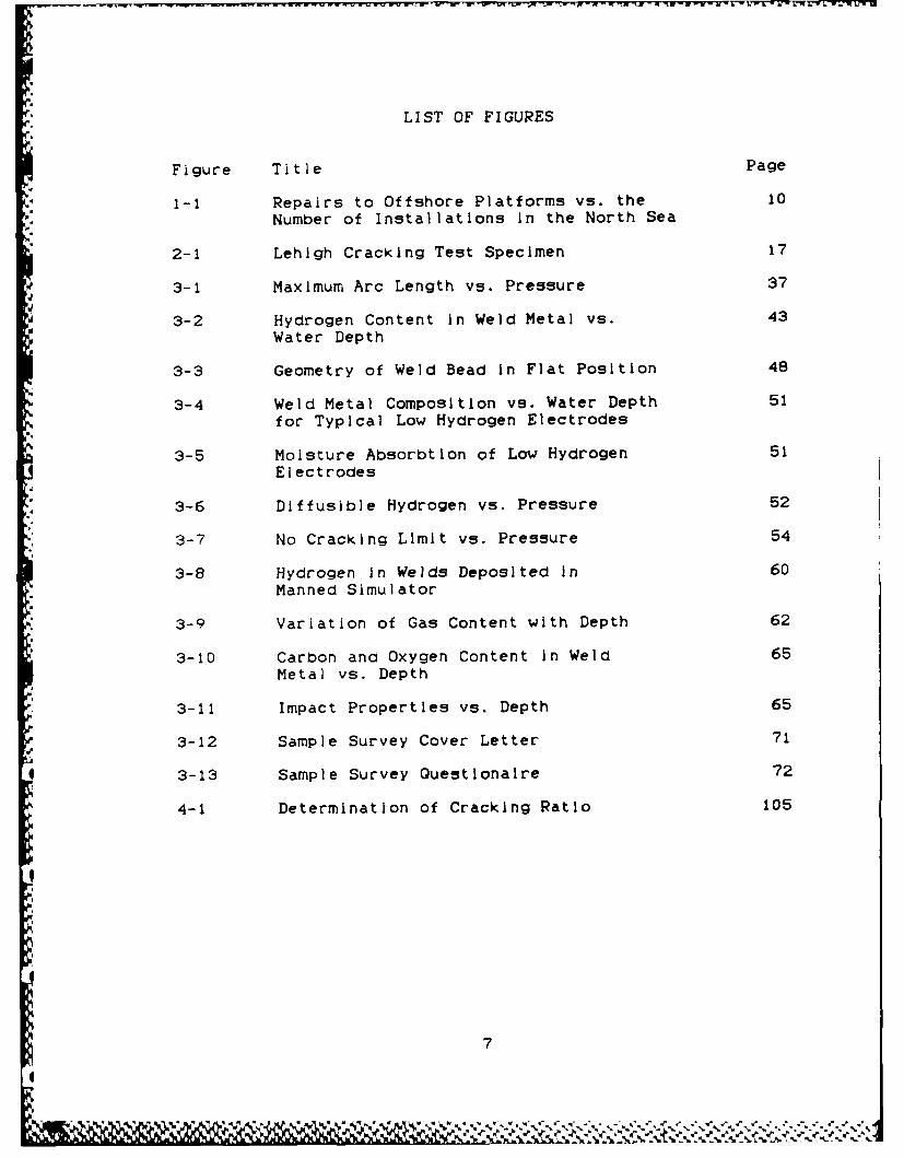
LIST OF FIGURES
Figure Title Page
1-1 Repairs to Offshore Platforms vs. the 10
Number of Installations in the North Sea
2-1 Lehigh Cracking Test Specimen 17
3-1 Maximum Arc Length vs. Pressure 37
3-2 Hydrogen Content in Weld Metal vs. 43Water Depth
3-3 Geometry of Weld Bead in Flat Position 48
3-4 Weld Metal Composition vs. Water Depth 51for Typical Low Hydrogen Electrodes
3-5 Moisture Absorbtlon of Low Hydrogen 51Electrodes
3-6 Diffusible Hydrogen vs. Pressure 52
3-7 No Cracking Limit vs. Pressure 54
3-8 Hydrogen In Welds Deposited In 60Manned Simulator
3-9 Variation of Gas Content with Depth 62
3-10 Carbon and Oxygen Content In Weld 65Metal vs. Depth
3-11 Impact Properties vs. Depth 65
3-12 Sample Survey Cover Letter 71
3-13 Sample Survey Questionaire 72
4-1 Determination of Cracking Ratio 105
7
- S, 'S, , 'S-- a s/, .¢ . .' v ,t , - ' *-, --. * \. , -... - . r .-.. , ...- ... :..

LIST OF TABLES
Table Title Page
2-1 Methods Available to Prevent Hydrogen 15Cold Cracking
2-2 Tested Steels - Alloying Elements and 34Property Summary
3-i Water Absorbtion Under Hyperbaric 59Conditions
3-2 Variation of Gas Properties with Depth 66(typical)
4-1 Testing Parameters 107
..
4-2 Lehigh Cracking Results 109
P8
I.
.,
Ip,
S .

I INTRODUCTION
The number of deep sea platforms, and consequently, the
number of repairs to offshore structures has Increased
dramatically in the last two decades. Figure 1-1 shows the
marked increase in the number of repairs and platforms from
1973 -1981 just in the North Sea.
These deep sea platforms and structures are in many
cases constructed of high strength steels. Consequently,
when welding repairs must be conducted on these structures,
engineers must deal with the problems of high strength
steel's sensitivity to hydrogen cracking.
When welding at deep depth, the problem of hydrogen
cracking is accentuated over normal atmospheric welding due
to the possibilities for increased hydrogen absorbtlon from
the underwater welding conditions.
It is apparent that to facilitate construction and
repair of these offshore structures that it is increasingly
imnportant to develop and utilize high strength steels that
are resistant to hydrogen cracking. High strength low alloy
(HSLA) steels are already known for their resistance to
hydrogen cracking.
It is the purpose of this thesis to examine the weld
cracking resistance of three types of steels when welded
under hyperbaric conditions. The Lehigh cracking test was
used to study the weldability of these steels at three
pressures (0, 100, 200 psig) utilizing the shielded metal arc
9
%0

(SMA) welding process. In pursuit of this goal a literature
and mail survey was conducted to gain an appreciation of the
state of the art of underwater hyperbaric welding using the
SMA welding process.
460-
CL
~0to
E
z
0
01

W - W
II BACKGROUND
This is the third thesis related to a research program
sponsored by the Iron and Steel Production Division of KOBE
Steel, Ltd. The title of the research program is "Research
on High Strength Steels with an Improved Resistance Against
Weld Cracking".
The objectives of this research program for KOBE Steel
are (1) to evaluate resistances against weld cracking of a
few selected types of high strength steels developed by Kobe
Steel, and (2) to study how the availability of these newO
steels can affect welding procedures used for fabricating
,A welded structures, especially large marine structures, and
their fabrication costs.
The high strength steels developed by Kooe Steel have
excellent resistance against weld cracking. They Include
controlled rolled structural steels and quench and tempered
structural steels. Both type steels are characterized by (1)
-markedly reduced carbon content, (2) relatively high amounts
of alloying elements, and (3) applications of precisely
controlled rolling and heat treatments. They are both in the
ell classification of hig strength low alloy (HSLA) steels.
The previous individuals and their theses who carried0
out earlier portions of this research study were:
.%
O

F.F. Hillenbrand, III, "Research on High-Strength Steels
with an Improved Resistance Against Cracking", M.S.
Thesis, June 1984.
M.J. Purcell, "Hydrogen-Induced Cracking in Three High
Strength Steels", M.S. Thesis, August 1984.
Cracking tests were performed using three types of tests
01 including the Tekken test, the Lehigh test, and the MIT test.
As anticipated, it was found that the Kobe Steel K-TEN8OCF
had significantly superior resistances against cracking
compared with HY-80 steel and T-1 steel Type A.
This thesis will endeavor to commence work that will0
contribute to the determination of carbon equivalent values
for steels that can be safely welded underwater in dry
hyperbaric conditions. The objective of this portion of the
.4 Kobe study is to investigate the suitability of the new type
steels for underwater welding, which is an Important
requirement for steels to be used for offshore structures.
Underwater welding techniques may be classified as 'wet'
and 'dry' welding depending upon the environment in which
welding operations take place. Welds that require good
metallurgical and mechanical properties are normally made
under dry conditions. Dry hyperbaric welding techniques, in
which the pressure of the dry welding environment increases
as the water depth Increases, are '7idely used for obtaining
hIgh-quality welds for repair and some new construction.
However, despite the term 'dry' welding, the welding
12

environment Is still very humid, thus providing a source of
hydrogen to enter the weld pool and promote hydrogen cold
cracking. Therefore, there is an extreme advantage of using
these new steels, If It Is proved that these new steels have
superior resistances against weld cracking than conventional
steels with comparable strength levels, when welded under
humid environments at various pressures. Then, one could say
that these new steels would be essential for fabricating
offshore structures.
This thesis will accomplish two goals. First, It will
summarize the state of the art of hyperbaric welding using
SMA welding. Secondly, It will perform experiments to help
2: determine the cracking susceptibility of varying grades of
carbon equivalent steels when welded under hyperbaric
cond i tions.
It is not the intent of this thesis to rehash background
Information already covered In Purcell's or Hillenbrand's
theses (References 25 and 26). Coverage of the subjects of
hydrogen cracking and weld cracking tests will be brief. The
reader is invited to review either the original sources or
the previous theses related to this research program for more
detailed Information on these topics
0. 2.1 Hydroaen Induced Cold ra.kjng
High strength steels are noted for their susceptibility
to hydrogen induced cold cracking. It is usually assumed
9.that this phenomena Is associated with the hydrogen
13
0%

embrittlement of martensite or balnite and that it is
initiated by high residual stresses developed in the weld
joint during cooling. The factors responsible for the
problem have been summarized In detail in the literature
(References 25 and 26). Conditions that cause hydrogen
cracking are tensile stress on the metal, temperature from
100 to 200 degrees C, a source of hydrogen, and a susceptible
microstructure.
Four general classifications of theories regarding
hydrogen cracking exist and are listed below:
VPlanar pressure theories
Surface adsorbtIon theories
Triaxial stress theories
Dislocation theories
Prevention of hydrogen Induced cold cracking involves
removing or minimizing one or more of the conditions that
cause the problem. A brief listing of the methods available
. is provided in Table 2-1.
2.2 Lehigh Weld Cracking Test
The Lehigh weld cracking test was selected to be used4:.
for this thesis. Its selection was predicated on the ease of
use, familiarity with the test , and the fact that the
preceeding theses related to the encompassing research
project (References 25 and 26) on the cracking tolerances of
0.
14
-1 .0 ,' 1A

TABLE 2-1
Methods Available to Prevent Hydrogen Cold Cracking
Minimizina Hvdrogen In the Weld
Minimize humidity In the air
Minimize moisture in the electrode
Keep welding surface and consumable clean of dirt, hydrogen
compounds (grease, degreasing flulds,oil), coatings
(oxides, paint), or moisture
Use low hydrogen electrodes
Use an inert gas environment
Preheat, Postheat
Use low hydrogen welding process.
Relievino Stress Throuah Proper Deslan and Fabrication
Proceo - es
Postheat
Minimize thermal stresses (Preheat)
Proper weld joint geometry and selection
Controlled low temperature stress relief
Vibratory stress relief
Peening
Prevention of a Suscentible Microstructure
Utilize fine grained steels
Control cooldown rate by adequate preheat or Interpass
heating to minimize grain growth
15

HSLA steels had used this test. The other obvious candidate
tests to be used were the MIT test and the Tekken test, which
were also used by Hillenbrand and Purcell. Although samples
were prepared of the Tekken test, time limitations prevented
conducting any welding at hyperbaric pressures. Further
tests are scheduled to be conducted by other Individuals.
The Lehigh weld cracking test has been a popular self
restraining test used In the US since Its development at
Lehigh University in the 1940's. It has been previously used
to rank steels and electrodes and develop adequate welding
procedures. Figure 2-1 shows the standard Lehigh test plate
specimen used in this research. A detailed description of
the Lehigh test and specimen preparation are provided In
References 1, 25 and 26. The restraint of the weld may be
varied with saw cuts on both the edges and the ends of the
plate. This option was not selected as It was desired to
achieve the maximum restraint attainable with the Lehigh
test. Even with no sawcuts, the level of restraint achieved
with the Lehigh test Is considerably less than with other
tests, I.e. the Tekken test, and may be less than In actual
structures, should there be any sawcuts.
Weld cracking was evaluated with single pass welds.
This simplified the testing process and experience has
Indicated that the root Is the most likely location for
cracking. Root cracking Is enhanced because the preheat
temperature Is typically at the specified minimum, the energy
16

U 12" I
S1/1/2" hole_8.X31/2 for plate < I"
5 /Z" for plate - I"
20
: P la te'/ 6• centerline 1/4I"
omit in plate <3/4" thick
Figure 2-1 Lehigh Cracking Test Specimen(Reference 1)
VV

input is often lower than the subsequent passes, and high
restraint and stress concentrations usually exist.
4 Determination of whether weld cracking had occurred was
accomplished by sectioning, polishing, and macroscopic
examination generally after 60 to 72 hours. Welds were
sectioned in three equally spaced locations.
A disadvantage of the Lehigh test is that it is a "go"
"no-go" test. In other words, if the test sample does not
crack. very little is learned. However, if the test plate
* -. does crack, all that is learned is that less restraint Is
@ required for the plate not to crack.
2.3 kkASels
The new types of HSLA steels were developed to satisfy
the requirements of the offshore structure and pipeline
industries for a low temperature high strength, high
- toughness steel that could be fabricated in adverse
conditions, i.e., easily weldable. This requirement, in the
1960's and early 1970's, prompted improvements in the
steelmaking industry for production of "clean steels', and
later easily weldable high strength ferrltic steels now
called HSLA steels. Essentially, these were new types of
C-Mn steels of bainite, acicular ferrite and reduced pearlite0
microstructures.
HSLA steels are ferritic and/or pearlitic with fine
grain size and carbon levels below 0.15%. HSLA steels have
18
Sj

potentially the same or better strength and toughness
- properties as other high strength steels, e.g., the HY
series, but HSLA properties are obtained by a combination of
'clean' steel processing, carefully selected small amounts of
micro-alloying elements, and heat treatments resulting In a
ferritic more easily welded microstructure. The
micro-alloying of HSLA steels consists of additions of small
amounts (less than 0.15 weight percent) of elements such as
Cb, V, Ti, Al, B, and N which function In grain refinement
and precipitation hardening to Increase strength and
toughness in a conventional C-Mn structural grade steel.
Further increases are achieved with nominal amounts of
conventional alloying of Cu, Co, Ni, and Mo along with
refinement of microstructure transformation products and
grain size during rolling, as well as optimization of the
type and distribution of the strengthening precipitates. The
results are steels which, because of low carbon content, are
extremely weldable without the use of many of the stringent
process controls required for other high strength steels.
(Note: it has been demonstrated that when a steel has less
than 0.10% C, good weldabIlity is more easily achieved even
with significant other alloying. (Reference 4))
2.3.1 HSLA Manufacture
The new approaches to steel making have several common
features which emphasize microalloying and thermomechanical
19
O.,

processing. A key element of the HSLA technology Is the
very fine grain size. Grain refinement is unique of all the
strengthening mechanisms (carbon equivalent, precipitation
hardening, solid solution hardening, work hardening, etc.) in
that it Is the only mechanism which simultaneously Increases
the strength and lowers the Charpy transition temperature.
The grain size is reduced through the addition of
microalloying elements, by a decrease in the rolling
temperature and an increase in reduction, and by the lowering
of the ferrite transformation temperature by either
A, increasing the cooling rate and/or increasing the
hardenability of the steel. (Reference 20)
HSLA steels are not only used In applications of heavy
plate products, but in sheet metal and lighter gauge
applications (i.e., the automobile industry), however, all
types of HSLA steels utilize the same features of grain
refinement to increase the strength and fracture toughness
properties.
2.3.2 Controlled Rolling
Prior to the advancement of HSLA steel technology, the
normal means to achieve a fine grained microstructure was to
utilize conventional controlled hot rolling.
The purpose of modern controlled rolling Is to obtain a
uniform, fine grained structure in the hot-rolled condition
and thereby to produce steel with high strength, good
r20,I
It, 0. I' 5
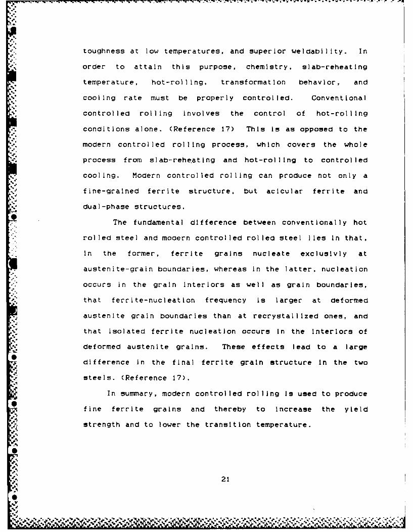
toughness at low temperatures, and superior weldabilIty. In
order to attain this purpose, chemistry, slab-reheating
temperature, hot-rolling, transformation behavior, and
cooling rate must be properly controlled. Conventional
controlled rolling involves the control of hot-rolling
!.. conditions alone. (Reference 17) This is as opposed to the
modern controlled rolling process, which covers the whole
.process from slab-rehe.ating and hot-rolling to controlled
. cooling. Modern controlled rolling can produce not only a
fine-grained ferrite structure, but acicular ferrite and
a' dual-phase structures.
The fundamental difference between conventionally hot
rolled steel and modern controlled rolled steel lies in that,
in the former, ferrite grains nucleate excluslvly at
austenite-grain boundaries, whereas in the latter, nucleation
occurs in the grain interiors as well as grain boundarIes,
that ferrite-nucleation frequency Is larger at deformed
austenite grain boundarIes than at recrystaIllIzed ones, and
that isolated ferrite nucleation occurs in the interiors of
deformed austenite grains. These effects lead to a large
difference In the final ferrite grain structure in the two
asteels. (Reference 17).
In summary, modern controlled rolling is used to produce
0fine ferrite grains and thereby to increase the yield
strength and to lower the transition temperature.
21
'VN
0S

2.3.3 Accelerated Cooling
Other strengthening mechanisns following the controlled
rolling process can be quenching and tempering, precipitation
hardening, or quenching and age hardening. It is sometimes
not even necessary to do a post controlled rolled heat
treatment if the controlled rolling Is done at finishing
temperatures below the austenitic decomposition temperature
(approx. 700 degees C.) (Reference 23) This process is used
in the manufacture of ultra low carbon bainltlc steel or in
V ferritic- pearlite steel. The drawback to this process Is'. that it is not possible to accomplish without extremely
powerful finishing stands not currently available In the US.
A recently developed process, only first Incorporated
into a manufacturing process in 1979, is the strengthening
process of accelerated cooling. In this process, increase in
tensile strength Is brought about by the fine dispersion of
hard second phase particles. The result is an even finer
grain size than that achievable through controlled rolling
alone at high finishing temperature, and an equally fine
grain structure as that achieved by low temperature0
controlled rolling processes. Contrasted to controlled
rolling, in which beneficial effect is obtained primarily by
grain refinement through the control of the austenitic
microstructure, accelerated cooling can stengthen the steel
while maintaining superior toughness by transformation
strengthening through the control of the gamma to alpha
22
%S

transformation. (Reference 18) Further, by appropriately
varying the process parameters, different combnations of
microstructure and hence mechanical properties can be
attained with the same chemical composition of the steel.
(Reference 22). Accelerated cooling has the distinct
A, advantage over quenching in that it does not involve a post
cooling tempering treatment, and thus, it is applicable to a
variety of as-rolled plate. For direct quenching, a
tempering treatment cannot be eliminated, and its application
'A is restricted to heat treated steels. It is also much cheaper
than the quench and temper process, and produces a product
A with better mechanical properties. Accelerated cooling, as
yet, has not been introduced to the US as an on line
manufacturing process.
There are even more variations on the means to
manufacture HSLA steels. This paper will not elaborate on
them as those processes produce steels that are not presently
in consideration for application to construction of offshore
plattorms.
2.3.4 Development ot HSLA Steel In the US
V The history of HSLA steel in the US goes back to the
* turn of the century when the Queensboro Bridge was being
built across New York City's East River. The Carnegie Steel
Company provided the solution to the bridge builder's desire
to minimize structural dimensions by manufacturing the first
23
04

HSLA steel (containing 3.25 % nickel) Development
continued, and It was learned that small additions of silicon
and manganese would also Increase strength. In 1933, US
Steel manufactured a 50 ksi yield strength weathering steel
which had attributes of high strength, high ductility, good
formability, good weldability and high corrosion resistance.
These properties were achieved through the addition of
alloying elements of C, Mg, Si, Cu, P, Ni, and Cr. At this
time, it was also discovered that Cu additives would also
provide a favorable precipitation hardening effect, but this
fact could not be capitalized on for manufacturing purposes
due to the lack of knowledge of how to effect it on a large
scale. It was subsequently learned that yield strength could
be further enhanced by addition of a small amount of Niobium
or Vanadium (micro-alloying), and controlled rolling (rolling
at lower than normal temperatures). This process caused
suppression of the austenitic grain growth and resulted in a
smaller grain size.
In 1967, pressured by Industrial demand to develop a
high strength, high toughness, weldable and economic steel,
International Nickel Corporation developed the first steel to
take advantage of Copper as a precipitation hardening agent.
They developed NICUAGE, which was an age hardenable Nickel,
Copper, Niobium steel with a -15degree F. DBTT. Development
of the arctic pipeline prompted further refinement of NICUAGE
by addition of Chromium and Molybdenum with prescribed heat
'I. 24
[I.%

treatments to even further lower the DBTT to -115 degrees F.
This steel was called IN-787. The strength and toughness
l evel of IN-787 prompted research into its compatibility to
ship construction and maritime applIcatIons. A three year
testing program resulted In the finding that it could be used
* -Z with confidence by the shipbuilding and offshore Industries,
and resulted in the maritime application steel designation
ASTM-710.
2.3.5 HSLA Steel in the US Navy
An example of a modern HSLA steel is the type steel0
4v currently used be the U.S. Navy, which is an acicular ferrite
steel. These steels have low carbon levels, can generate
yield strengths over 80 ksl and have a very low DBTT of less
than -100 degrees F. The type steel selected by the Navy Is
ASTM A710. This steel was developed by the International
Nickel Company and when manufactured to government
specifications is called HSLA-80. The steel has low carbona.
a. (0.04 - 0.08) for good weldabilIty and uses C, Mn, Ni, Cr,
Mo. Cu, Co. and Al as alloying elements, their purposes for;0
use which are listed below:
d1% manganese - ties up sulpher
a., reduces hi temp transformation products
" provides solid solution strengthening
copper - precipitation strengthening
O chromium - optimize precipitalon of Cu
to.
00.
25
.4%
molybdenum - optimize precipitalon of Cu
nickel - prevent hot shortness from Cu
increase toughness
-' aluminum - deoxidizing, grain refining
columblum - retard austenite grain growth
(Reference 4)
After quenching, the structure consists of a mixture of
very fine-gralned ferrite, acicular ferrite and a
martensite-austenIte microconstituent, together with a high
dislocation density. Aging produces an even finer dispersion
of epsilon-Cu precipitates. The fine scale microstructure is
the key factor producing the good combination of strength and
toughness. (Reference 19)
The key advantage of HSLA steels In naval ship
construction is their inherent weldability and attendent lack
of pre-heat requirement as part of the welding process.
Substitution of HSLA for HY-80/100 can yield cost savings mot
only through lower fabrication costs but through lower
material costs as well. Weight savings can additionally be
achieved by substitution of HSLA steels for lower strength
high strength steels (HTS), since smaller cross sections can
be specified. Further, the weight savings can be achieved
with only an increase in the cost of the steel plate itself,
since fabrication of HSLA and HTS steels are accomplished by
essentially the same process. (Reference 4)
2
26

2.3.6 Weldability
Weldability represents a good deal of the cost savings
to be expected with HSLA use. Traditional high strength
steels are very susceptible to hydrogen cracking in the heat
affected zone (HAZ) from welding. In order to eliminate the
hydrogen damage during welding, the plate must be preheated
before welding. This is a very costly and labor intensive
procedure, and is a main cost driver in fabrication and
-- repair. HSLA steels have virtually eliminated preheat
requirements before welding. (Reference 24)
Some of the most significant factors being investigated
with regard to the welding of fine-grained low-alloy steels
for construction purposes are the requirements for low
welding energy input and limitation of Interrun temperatures
so as to achieve welded joints with good mechanical
properties in the weld metal and HAZ. Low welding heat Input
has been shown to be necessary to minimize the formation of
coarse grain structure in the HAZ and to avoid secondary
carbide precepitation. These defects can Increase the
* susceptibility of the HAZ to crack. However, the low welding
energy requirement means a reduced weld bead cross section
per run, and hence substantially more weld runs are required
to fill a given joint volume. (Reference 21)
Weldability studies indicated that weld metal and HAZ
properties were acceptable with current welding procedures
* ana practices (i.e., cooling rates kept above 10 degrees F.)
-27
The elimination of preheat as a requirement was validated,
and it was further determined that HSLA was less susceptible
to hot cracking than HY series steels. Large scale
production weldability tests demonstrated that cracking only
occurred when the HSLA was welded In extreme conditions
(i.e., outside specified welding parameters). (Reference 4)
It Is noted that some HSLA steels have been specifically
developed to retain significant toughness levels In the HAZ,
even when welded with high heat input, high deposition rate
processes. These type steels have been specifically
validated as appropriate for maritime use by a research
project sponsored by the American Bureau of Shipping, the
Society of Naval Architects and Marine Engineers, The US
Maritime Administration, and others. These type steels were
all manufactured with either Thermomechanical Controlled
Processing or Thermomechanical Controlled Rolling (both,
processes not available in the US), and possess extremely low
sulfer levels, low carbon equivalent levels, fine ferrite
-'! grain size, and intentionally added titanium.
2.3.7 Cost
The net cost differential of HSLA steel over a typical
high strength steel such as HY-80 has been estimated to be
$0.40 to $0.90 per pound of steel; or 5% to 15% less cost
than for HY-80/100 (Reference 24). It is important to note
that this does not include an estimate for other HSLA steel
28
% %

advantages beyond material cost and preheat, which are
related to the capability to easily weld the materials.
These include lessened non-destructive testing, the ability
to weld through paint primer, reduced requirement to NDT the
back-gouging of root passes, and no necessity to grind off
temporary attachments instead of flush removal as are
required for HY-80. (Reference 4)
2.3.8 Comparison of US/Japanese Manufacture of HSLA Steels
The US currently lags well behind the Japanese In the
manufacture of HSLA streels. Currently the Japanese make
stronger, cleaner steel than the US is capable of making.
Their clean steel technology is better than the US, as
evidenced in their more extensive and superior ladle
treatment. The reduction of sulfer, phosphorus, nitrogen and
oxygen in a steel improves the toughness In both the base
metal and HAZ. The sulfide or phosphide formed in a steel
can dissolve and precipitate In the HAZ lowering toughness.
Thus, Japanese steels are achieving better toughness, with
less additives, making their steel a more weldable steel.
TMCP, using accelerated cooling, and TMCR, a post hot
controlled rolling procedure In the austenitic-ferrite two
phase region, have not been introduced Into any US steelS
mill. Thus, the US is not able to manufacture many of the
types of HSLA steels that are possible with current world
technology.
29
.

The poor state of US steel making technology is
reflected In its research capability. As an example,
Bethlehem Steel Sol Its research facilities to Lehigh
University - and now rents back a small portion of the space.
Another company, which had a research staff of 1300 plus
employees now has only around 200. Some Japanese companies
now have over 1600 employees In their research departments.
An example of the problems this presents for the U.S. is
that the Navy wants to buy US steel, but no US Steel
manufacturer can provide the quality steel the Japanese make.
It is not cost effective for US steel manufacturers to@
upgrade a steel mill capable of making 6-9 million tons per
year of steel just for the US Navy, which might buy only
one-half million tons per year, .f they should get the
contract. The US manufactures a lot of HSLA steel, but most
of it is sheet steel for the automotive industry. The
unquestionable leader in plate steel remaits the Japanese.
2.4 Steels Being Evaluated
Three type steels were evaluated for their hyperbaric0welding performance. All steels had ultimate tensile
strengths around 50 kgf/mm2 (71 ksi) and yield strengths
around 40 kgf/mm2 (57 ksi). The Type I steel is a
conventional type steel whose properties were obtained
through normalization. Its PCM was the highest at 0.228
(C.E. = 0.373). Both Type II and Type III steels are HSLA
30
steels whose properties were obtained from controlled rolling
and accelerated cooling. The Type II steel had a PCM of
0.193 (C.E. = 0.315). The Type III Steel had a PCM of 0.154
(C.E. = 0.292). Table 2-2 provides a summary of principle
alloying elements and properties.
2.5 Underwater Weldina
The advances in technology involving underwater welding
have been generated from the increasing number of underwater
platforms existing in the world. These underwater platforms
will eventually require repairs, and the scope of the repairs
0.will eventually require underwater welding. A number of
welding processes have been used and studied for underwater
-4 applications. The most commonly used are the arc welding
processes including the shielded metal arc (SMA) process
using covered electrodes, the gas metal arc (GMA) process,
the gas tungsten arc (GTA) process, and the flux cored arc
(FCA) process. Other welding processes that have been used
and/or studied Include submerged arc, plasma arc, stud,
thermit, friction, resistance welding, etc. (Reference 12).
The American Welding Society (AWS) has classifIed the
underwater welding techniques on the basis of the environment
in which the welding takes place, as follows:
0!
31
P l
S...4.

A. Dry Chamber Techniques. Welding takes place In a dry
environment.
1. One-Atmosphere welding. Welding is performed in a
pressure vessel in which the pressure is reduced to
approximately one atmosphere Independent of depth.
2. Hyperbaric Dry Habitat Welding. Welding is performed
at ambient pressure In a large chamber from which
water has been displaced by a gas to provide a dry
environment. The welder/diver does not work in
diving equipment.
3. Hyperbaric Dry Mini-Habitat Welding. Welding Is
performed in a simple open-bottom dry chamber which
accommodates the head and shoulders of the
welder/diver in full diving equipment.
B.. Portable Dry Spot Technique. Only a snall area is
evacuated and welding takes place In the dry spot.
C. Wet Technique. Welding is performed in water with no
special device creating a dry spot for welaing. In manual
wet welding the welder/diver is normally In the water.
(Reference 7)
.. By far the most popular underwater welding
classifications used have been the wet technique and theH, hyperbaric dry habitat welding.
.3

Major advantages of wet welding are Its simplicity and
its ability to be used in the wet environment. The major
shortcoming is the rather poor weld quality compared to that
-' of welds made in air (Reference 12) clue to the intensive
cooling of the welds, resulting In the formation of quenching
structures, and the high content of diffusion-mobile hydrogen
-- in the weld metal. All factors which promote the occurence
of cold underbead cracks, the decrease of toughness and
impact resistance in the metal. Underwater wet welding
processes are widely used for repair jobs because of this
process' significant cost saving over other underwater
.- welding methods which yield higher quality welds.
Since hyperbaric dry habitat welding is clone in the
completely dry environment, the quality of these welds can
match the quaIty of welds made in normal atmospheres and
pressures. This type process is used for critical jobs where
structural integrity and fatigue considerations are
paramount. The major problem of this process is the
extremely high cost.
This thesis only addresses that facet of underwater
welding concerned with the use of SMA welding In a hyperbaric
dry environment.
.w
33
0e

TABLE 2-2
TESTED STEELSALLOYING ELEMENTS AND PROPERTY SUMMARY
TYPE I TYPE II TYPE III
UTS (kgf/mm2 ) 54 51 53
Y.P. (kgf/mm2 ) 39 38 34
Elong. (%) 29 29 28
C %) 0.15 0.13 0.08
S (%) 0.33 0.21 0.35
, Mn (%) 1.34 1.11 1.11
* P (') 0.013 0.015 0.008
S (') 0.007 0.009 0.001
Al(%) 0.024 0.033 0.031
Ni () ---- ---- 0.40
Nb (%) 0.031 ---- 0.011
Ti () ---- ---- 0.007
Ceq (%) 0.373 0.315 0.292
Pcm ('%) 0.228 0.193 0.154
Ceq(%) = C + Mn/6 + (Cr + Mo + V)/5 + (Ni + Cu)/15
Pcm(%) = C + Si/30 + (Mn + Cu + Cr)/20 + NI/60 + Mo/15 +
V/10 + 5B
O.3
34
.............................................

iIII HYPERBARIC UNDERWATER WELDING USING
THE SMA WELDING PROCESS
3.1 History and Overview4.
The concept of underwater dry habitat welding on pIpelines
essentially began with the 1954 patent by Osborn. He
developed a design of an underwater enclosure that was to
become the predecessor of contemporary welding habitats. The
concept was too futuristic for its time, however, and did not
receive much attention until shortly before It expired, with
the large advent of underwater structures and pipelines.
* Commencing around 1965, several companies Involved In diving
and related activities built various types of underwater
°.1 welding habitats and performed repairs on offshore platforms
and pipelines. The techniques originally developed for
pipeline tie-in and repair have since been adapted to riser
tie-ins on concrete platforms, repair of damaged offshore
structures, and many other applications. (Reference 7)
Underwater dry habitat welding is conducted on a routine
-, Dasis at depths in excess of 150 m (500 ft) and have been
* accomplished at sea depths of 320 m. (Reference 8) Most of
the work thus far has been done In the Gulf of Mexico and the
North Sea.r4 .
The control of welding parameters, gas shielding and
selection of consumables all become more critical with
increased operational working depth. In the view of one
welding contractor (Reference 15), SMA welding reaches its
k.%.
U' 35
~.~ ~~ A .' t

work ing imi t at around 300 m clue to the Increased
susceptibility to hydrogen cracking. This particular
contractor endorses GMA welding for deeper depths.
One of the primary effects of welding under pressure Is
the constriction of the arc and the volumetric shield
surrounding the arc, this results In a decrease In arc
stabililty. Due to the reduced arc stability, smaller
diameter welding consumables, typically 2.5 and 3.2 nun
electrodes, are used for positional welding when using the
'a SMA welding process.
Additionally, the fusion characteristics of SMA welding
deteriorate with pressure, it Is therefore necessary to
ensure that short arc lengths are maintained In order to
achieve the required weld properties. Figure 3-1 relates how
* the maximum arc length shortens with pressure.
* . Weld metal chemistry also changes with pressure In SMA
welding. Gases from the environment are absorbed at greater
rates than in normal atmospheric welding which can affect
impact values and crack susceptibility, Including hydrogen
'acold cracking. Thus, preheat temperatures are higher, and
welding consumable hydrogen/moisture control Is more
stringent than for conventional atmospheric welding.
Additionally, post weld hydrogen diffusion treatments have
sometimes been specified to reduce the level of hydrogen
retained In the welded joints, typically at temperatures of
200 to 254 degrees C.
0.6
'%a

mm
.4 20
(0 drooping characteristicsPower wurces vertical characteristics
& copper
10
eI I I I I I I -
0 5 10 15 20 25 30
4,%
L4
Id
U
Fiue3i MxmmAc eghv.Pesr
o (eeec 3
j37
I

3.2 Underwater Welding Techniaues
High quality connections which satisfy the most
stringent specifications can be made by current welding
techniques. The optimum welding technique or combination
thereof appears to be a function of Individual welding
contractor preference, proficiency or expertise. A
combination of using GTA welding for the root and hot pass
followed by SMA welding for the fill and cap passes seems to
'-- . be the most popular consensus of preferred welding sequences.
However, the advantage of only using SMA welding or only
using GMA welding has been espoused In the literature.
3.2.1 Inert Gas Shielded Methods
The inert-gas shielded processes are able to produce
welds of a much lower Impurity content. Carbon will in
general not be Introduced into the weld, and although
hydrogen may be picked up from the humid habitat atmosphere,
hydrogen absorbtion will be overall much smaller, an average
of about 5 ppm in the weld metal from welds made at 500 ft
* •(16 bar) being virtually Independent of the habitat humidity.
(Reference 8)
3.2.1.1 GTA Welding
GTA welding was initially used for the entire weld by
one welding contractor, as it met the requirements for-,.
N' producing a root bead of a convex contour with satisfactory[O.
metallurgical and mechanical properties. (Reference 7)
38
S
'4... -. , * 4 4 * * *~ *4 ~ . .. , . j . . . -.

However, due to it being a very slow process, Its use Is
currently confined to welding the root and hot passes. The
,- disadvantage GTA welding posed to another welding contractor,
which does not use GTA welding, Is related to this particular
contractor's desire to work In "shirt-sleeve" conditions
without breathing masks. GTA welding was eliminated since
argon has a narcotic effect and connot be effectively removed
by the gas regeneration system. In addition, GTA welding was
considered too slow and subject to magnetic arc blow,
V.: possibly requiring demagnetization of the components to be
welded. GTA welding In helium was found too difficult to
perform. This welding contractor's extensive development and
research has concentrated on SMA welding, GMA welding and FCA
welding. (Reference 11)
"" 3.2.1.2 GMA WeldinQ
People who endorse GMA welding provide the following
attributes of this technique over that of SMA welding. The
- absense of an external coating and reduced moisture
- absorption means that for certain materials, welding can be
done without preheating. The alignment and joint tolerances
are greater. The process is capable of higher deposition
rates with no down-time for electrode changing. Better
mechanical results than the SMA welding were achieved with
respect to ductility bending, elongation and toughness. GMA
welding Is not affected chemically by pressure. Welder
training is simplified. Penetration is easier, visibility
39
- .. .. .

%I , _' .-- -r -".- - _. . '. -7x-L_ .- ;
and handleability of the arc are improved. Sensitivity to
hydrogen cracking is considerably reduced. As opposed to the
SMA welding process, which was felt to be intrinsically
limited in depth to approximately 300 m, the GMA process has
no depth limit. (Reference 15)
People who do not endorse the GMA process cite these
disadvantages of the process. Although the welding speed of
the GMA process is high, it tends to produce a concave-shaped
root pass; also, lack of fusion possibilities and wire feed
problems tended to offset the gain In deposit rate.
(Reference 7)
3.2.2 SMA Welding
The SMA welding process using low hydrogen type
electrodes is currently the most widely used underwater
welding process. Good penetration with a reasonable welding
speed can be achieved under hyperbaric conditions. (Reference
7) By modification of the coating, using a short arc
technique, and increasing the arc voitage, stable arc welding
* conditions can be achieved at pressure. (Reference 11)
Although the electric arc characteristics are affected a
little by pressure, they are generally excellent. It Is
important to prepare the electrodes very carefully and
transfer them perfectly dry. Using dry electrodes and the
highest energy input possible are two key factors In
minimizing hydrogen cracking. String beading procedures
40
6%I&.,

which are used produce good toughness qualities but is
unfavorable as far as hydrogen cracking and hardness In the
HAZ are concerned. Less hardenable metals are recommended
for hyperbaric welding with carbon equivalents less than 0.40
if possible. (Reference 15) Welding machines should have
excellent dynamic characteristics and a device for restriking
the arc. (Reference 11)
The effect of pressure does lead to increased absorbtion
of hydrogen (on the order of 2.5 times the content In surface
welds), oxygen and carbon and to reduced contents of silicon
* and manganese. Utilization of inert gas atmospheres
minimizes the problems associated with impurities entering
the weldpool, but does not eliminate the problem, thus
setting an intrinsic depth limit to SMA welding at around 300
m..(Reference 8)
One of the most favorable characteristics of SMA welding
over GTA and GMA is that considerably less technical
knowledge is required to achieve optimum performance In deep
waters. However, since the SMA process with low hydrogen
electrodes tends to produce marginally acceptable roots in
open butt joints, the GTA process is generally used for the
root bead and increasingly for the hot pass and first fill
pass also.
00
.. 41e
'a" :';. .. . . . . -,. o . ,. . .:. ...:, , , .. ....

.~~~~~-I V.7~ I- q. k-W~ W ~ 7 * ' - -
'p
3.2.3 FCA Welding
FCA welding, because it permits speedy welding, is
widely used by those with access to a suitable consumable.
A significant advantage of FCA welding over SMA welding is
demonstrated in Figure 3-2, which demonstrates how there is
significantly less hydrogen absorbtlon into the weld metal
with FCA welding.
3.3 Environmental Control of the Habitat
To attain satisfactory weld properties, the habitat must
be dry and environmentally controlled for temperature. To
dry the habitat, seals are created at each Junction with the
structure. The water is then excluded by gas pumped into the
habitat and electrically operated environmental control
*" equipment mounted in the habitat wall is then used to heat
and dry the area. (Reference 16) One environmental control
system currently being marketed consists of a circulation
system of two blowers that passes the atmosphere continuously
through a carbon dioxide absorber, a water vapor absorber
filled with molecular sieve drying agent and different
catalyzers for hydrocarbons, nitrous gases, carbon monoxide
and hydrogen reduction. This system can absorb a heat load
of up to 50 kw generated mainly by the welding In the chamber
The pressure Inside the chamber is equal to the
hydrostatic pressure of the particular depth. The use of air
42
V -. ,

.' d
1.4
D'q ,,. ,., 1.1 h ,, I,,A11O0 of wow I
'- ~~~10, /lwro w
N 4 Fiurnrd oire
U
V% " 10 20 30 b.n
Figure 3-2 Hydrogen Content in Weld Metal vs. Water Depth(Reference 15)
O.
- ..
43
S%
:. ,,,,;-"."-"-" . . . ,. ,. ,, ,. . . . .. ,. . . . . . . ..
is, however, limited by the partial pressure of oxygen. One
limitation used by some is that of 70 m, beyond which there
Sis a risk of oxygen enrichment effecting an alteration of the
lungs and the nervous system. (Reference 13) Pressure also
I ntensifies the noxious effects of carbon monoxide, carbon
dioxide, and ozone on the body. The other significant
consideration with Increased oxygen partial pressure is the
increased flammability of the environment. At a depth of
only 46m, clothing burns In air at six times the rate of
burning at atmospheric pressure. In the opinion of one
source (Reference 9), compressed air is not a safe working
environment even when the depth exceeds only a few feet. My
personal conversations with experts In the field indicated
that compressed air was routinely used in welding tie-ins at
depths of around 50 feet.
Apart from the danger to the diver of fire,
contamination by air can have a devastating effect upon The
soundness and mechanical properties of the weld metal. The
SMA welding process uses carbon monoxide and carbon dioxide
as shielding gases. These protective gases can easily be
produced by the calcining of chalk, crushed marble or
limestone included in the flux. Alternatively, or In
addition to the lime, cellulosic materials may be added,
S. which produce similar gas as they burn at the electrode tip.
Estimations of the volume of shield generated by the melting
and burning flux of a typical SMA welding electrode is about
equivalent to a CO2 gas flow of 12 litres per minute.
44

The effect of pressure in shrinking the size of the SMA
welding protective gas shIeld is very marked and becomes
evident even at a depth of only a few meters. At a depth of
only 10 m the equivalent gas shield flow rate is reduced to
about half so that even at thIs shallow depth, lack of
adequate protection may begin to show its effects. Failure
to maintain an extremely short arc under hyperbaric
conditions have resulted in severe escalations in nitrogen
content resulting in large reductions in charpy V energy.
The very short arc length necessary to preserve shielding in
an atmosphere of nitrogen, even under only slight hyperbaric
pressure, can only be maintained in positional welding with
extreme difficulty. (Reference 9) Additionally, it has been
shown that at 40 bar a change in arc length of only imm will
entail a consequent change in arc voltage of 3 volts with
significant transient effects. (Reference 7)
For the above stated reasons, hyperbaric welding in
habitat environments of nitrogen and oxygen are not usually
recomended. For dry habitat welding repairs at depths beyond
17m of seawater, helium or argon based atmospheres with
controllea oxygen levels are preferred. (Reference 14) From
the aspect of the achievement of weld deposits of excellent
k mechanical properties, the provision of a pure noble gas
atmosphere is effective; however, the performance of someV.ome
welding electrodes Is impaired by the absence of oxygen.-p..
Welding electrode fluxes are designed to work in air and
normally contain large additions of ferro alloys, the purpose
45
A1

: .%
of which is to combat oxidation and to supplement some of the
alloy content, such as manganese, which may be lost thereby.
In the absence of oxygen, undesirable changes in the
properties of the slag may result, leading to changes in
mobility, viscosity, detachability and chemical composition.
,' Sometimes these effects can result in poor weld coverage,
leading to bad weld shape and difficulties In handling.
Adding a small dose of oxygen to the shield, the amount
dependent on the pressure, has been found to overcome these
problems. (Reference 9) Despite the use of the inert
atmospheres in hyperbaric welding, the danger of hydrogen
cold cracking is still present from the hydrogen present in
the chamber and in the electrode flux in the form of
moisture.
3.4 Hyperbaric SMA Electrodes
It becomes readily apparent that most electrodes one may
use under normal atmospheric pressure conditions cannot be
used under the hyperbaric pressures experienced In the repair
of underwater platforms. The effect of pressure on welding
* characteristics Imlts the size of the eIectrode and type
fluxes suitable for use under high pressure conditions.V 3.4.1 Weld Bead Geometry
Due to the pressure effects on the characteristics of
the electric arc, the electrical variables of welding are
also similarly affected by a modification of the physical
5, properties of the plasma. This results in a change in the
46I-.

geometry of the weld bead made under pressure. In one study
_=_ conducted on beads made In the flat position with E7018
'
electrodes, the geometry of the bead was shown to be altered
by pressure, In particular In the range corresponding to a
depth of 50 m. (See Figure 3-3)
3.4.2 Electrode Da eeiameter
In vertical up welding, test results showed that the
electrode diameter as well as the type of covering are
Important factors that may Increase the changes In bead
'.'-3.. Cosabeovrn
geometry. It appears that raising the arc temperature
SsIncreases the fluidity of the molten pool and alters surface
tensions, thus making electrode diameters above 3.5 nmn 0/8
i nch) pract icall Iy use Iess. Selecting the proper electrode
diameter becomes a determinant In avoiding defects such as
porosity and slag Inclusions.
3.4.3 Consumable Coverino
Contrary to what happens at atmospheric pressure, for a
same class of electrodes, the composition of the covering
becomes an essential variable that may determine the
usability of the electrode under hyperbaric conditions.
.5.'.(Reference 13)
Al
.5%
S.'T.d ' ',' O E -. . - ' ' "
' ' ' ' -. .- L . ,-''

L
S s/S - dilutionhh/L *form factor
S's crs Ctse ctionl
of deposited mewtal
4... L
7 35
030
5 4
80esur (ba~(b r ) presre (b )
A0 515 32? 53
h
(esRefne 13) pewe br
4 45
44012.3

Many SMA electrodes which work well at atmospheric
pressure perform so badly at even moderate hyperbaric
pressure as to make them unusable. As pressure is increased,
problems begin to be encountered, such as short circuits, arc
outages, etc. Welding may become increasingly dificult,
resulting in aeterioration in appearance and impossible slag
detachability. As depth exceeds about 150 m,, problems with
weldability, especially for all position welding, may
necessitate a progressive reduction In electrode size until
the maximum usable size reduces to 2.5 to 3.25 mm. This
.. Airestriction, leading as it does to further reduced current
and hence thermal input, compounds the hydrogen cracking
problem, making preheat and control of Interpass temperature
even more essential . One rough guide was, because of the
total effect of these variables, was to increase the preheat
about 100 aegrees C over and above that which would have been
- required for the same sized weld at normal atmospheric
pressure.
Many welding contractors use proprietary consumables
that enable them to minimize undesirable features. Reference
15 documents the success one contractor had in attaining
significant improvements in welding consumable
characteristics. The electrode they developed, when welded
S.under hyperbaric conditions, In addition to restoring some of
the impact properties, showed a low carbon content, was less
hygroscopic, had better handling characteristics and aS@.
readily detached slag. The improvement In their electrode
49

%.
performance over conventional electrodes is provided in
Figures Z-4 and 3-5. This figure also shows the Increase in
gaseous absorbtion with pressure. The opinion of this
contractor was that, while weld characteristic at 300m are
perfectly adequate for all the major pipe welding
specifications, comparison with results at 150m suggests that
impact properties of the weldment would not be achieved at
depths significantly beyond 300m if low Ni content electrodes
are to be used. (Reference 11)
50
1.% ' 1

C .. W D
0.20
Figure 3-4 Weld Metal Composition vs. Water Depth for Typical* Low Hydrogen Electrode (Reference 15)
N~bow USKUJ 910016aq
sp" vpbx iot-f
~151
% %

3.5 Hydrogen Cracking of Underwater Welds
3.5.1 Increased Hvdroaen Absorbtion
Due to the fact that the ambient pressure influences the
rate of atomic hydrogen absorbtion into solution in the
molten weld pool (See Figure 3-6), the effect of hydrogen
from whatever source, e.g. moisture In the flux coating, high
humidity, hydrocarbon deposits, etc., Is more marked under
hyperbaric conditions and explains the increased
susceptibility to cold cracking of welds performed under
cclOOg deposited metal
p 30°E 13I
.- .20
0.
P bar0 5- 10 15 20 25 30
Figure 3-6 Diffusible Hydrogen vs Pressure (E7013 and E7018)(Reference 13)
L 5207.

%.4
hyperbaric conditions. Increased hydrogen absorbtion in
hyperoaric welds has been reported in numerous research
studies. (Reference 8). One Investigator reported that an
increase in pressure from 1 bar to 8 bar was accompanied by
an Increase of hydrogen of two or three times (Independent of
the dampness of the electrode flux). The significance of
-nearly doubling the hydrogen content of SMA welding deposits,
even at a depth of only 60 m, Is of the greatest Importance
to those considering the use of this process for the welding
of thick steels, especially when the steels are of
* comparatively high carbon equivalent. (Reference 6)
In addition to the Increased solubility of hydrogen at
higher pressures, another rationale has been presented to
explain the increased concentrations of hydrogen at increased
pressures. One of the effects of the changes in heat
distribution between cathode and anode as pressure Increases
is that the proportion of the heat developed at the anode
increases. Perhaps as a consequence of this phenomena, the
droplet size decreases and the droplet frequency increases.
The increased surface area of the total sum of the droplets
together with perhaps the longer time they spend in the arc
atmosphere is proposed as an explanation for the Increased
hydrogen absorbtion. (Reference 6)
The increased susceptIbility to hydrogen cracking Is
iIlustrateO by Figure 3-7 which shows that the critical
cracking stress decreases as the pressure rises.
53
"'.

Stress Vickers
J HV 5
00
I--am
No racin - _____ ______ _____
V'V
Figure 3-7 No Crackrng ing s rssr13)0
10037
NoCrckng - 6
54

~,i
3.5.2 Prevention of Cold CrackinQ
An analytical/empirical system for preventing cold
cracking in steel weldments has been developed by a group of
Japanese researchers and Is presented by Masabushi In
Reference 1. They propose the following relationship:
H' KsPw ( % ) = PCM + 60 + 40,000
U.
where: Pw(%) = cracking sensitivity of thewe I d men t
PCM = Carbon equivalent (JIS)
H = diffusible hydrogen per 100graips deposited weld metal(cm1/100 g)
Ks = intensity of ristralnt of the
joint (kg/mm )
-. Once the cracking sensitivity is determined, this can be
relatea to critical cooling times, pre- and postheat
temperatures.
Essentially, this formulation says that the contribution
* that hydrogen makes towards cold cracking in the welding of
structural steels can be expressed in terms of:
The effective Increase in carbon equivalent
-.
(equals)
IU. the diffusible hvdrooen In the weld metal60
55
-....,'.',2..,.','.',...',.,. €..... . . . ., ,...... ......... , ,..... . ... ,... . .,., .,,,. ,,•, .,-. ' , % ' . " ' - ', % ¢.; ,'. L '' '.$"..;- ,: ..'",",,-' ,".,, . . ', . .,"..•.:. ... " ' " ... ' ". . . '-... . .. ". -,." . ,"•,-,-

The English researcher, Allum, has come up with a similar
formula for establishing a cracking parameter. (Reference 6)
These formulations indicate that the effect of a small
increase in the hydrogen content of the deposited weld metal
- can have a severe effect upon the cold cracking propensity of
a typical weld connection. The difference In the reported
hydrogen content of SMA welds made at 1 bar and at 8 bar is
equivalent in loose terms to an increase in the carbon
content of the steel of about 0.1%. This difference is about
equal to the range of carbon content between the least
,4,: weldable and most weldable structural steels In common use
today.
3.5.3 Pre- and Postheat
The prevention of hydrogen cold cracking depends upon
many variables, including: the composition and carbon
equivalent of the steel being welded, the quench rate, the
hydrogen content of the weld metal and HAZ, the restraint
stress, the steel thickness, the welding process, the thermal
input, ambient and preheat temperatures, etc. These
variables all interact and contribute to hydrogen cold
cracking within one of the previously mentioned theories.
Whatever theory of hydrogen cold cracking is espoused,0.
the resultant practice is that It has become normal practice,
for the welding of structural steels of significant
thickness, to use low hydrogen electrodes, to keep them dry,
and often to preheat so as to facilitate the diffusion of
56O.
hydrogen out of the joint while It Is still warm. The extent
to which these precautions need to be applied will, of
course, vary with the app]licat ion. For most underwater
welding jobs on offshore platforms mentioned In the
literature, preheating has been applied. (Reference 6)
* .(Note: One of my conversations with an expert In the field
Indicated that the application of preheat Is not as widely
practiced by Mexican welding contractors as It Is by US and
-. , North Sea contractors.)
Preheat temperatures are generally higher and welding
consumable control Is more stringent than for conventional
atmospheric welding. Additionally, post weld hydrogen
diffusion treatments have sometimes been specified, typically
at 200-250 degrees C. to reduce the level of hydrogen In the
joints (Reference 14)
Preheating to high temperature is not always favored by
welders confined in the small space of a habitat and
surrounded by the heavy atmosphere of a compressed gas. An
alternative to preheat has sometimes been to Increase the
thermal Input of the welding arc. (Reference 6)
3.5.4 Humidity Contribution to Hydrogen Absorbtion
The contribution of humidity to the hydrogen that
eventually will cause hydrogen cracking In hyperbaric welds
becomes significant under certain conditions. It would be
expected that higher hydrogen contents may be expected when
welding in a humid habitat, due to moisture absorption In the
057
et4~~%

i .
-
electrode coating and to direct absorbtion Into the exposed
annular surface of the weld pool. This Is supported by the
work of Berthet and Gaudin (1976) which showed that where the
critical stress attained was slightly more than one-half the
yield stress In surface welding, the stress limit In
hyperbaric welding was about 15% of the yield stress In a
- fairly dry atmosphere, and zero at saturation. (Reference 8)
The process of hydrogen absorbtion Into the weld pool
,. can be analytically developed using vapour pressures,
solubility factors, and reaction temperatures to yield an
effective hydrogen level. Using this analytical model and
- substantiating their conclusion with experiments, several
researchers (References 6 and 8) have demonstrated that
direct absorbtion of hydrogen from the ambient humidity is
not a major contributor to the hydrogen levels unless the
electrode has been baked to a very low initial water content
(which is the case in virtually all hyperbaric welding Jobs).
The risk of increased hydrogen absorbtion must be
assumed to be present in a humid habitat and is related to
the time of electrode exposure, the relative humidity, and
the initial water content of the electrode.
". Reference 10 reports on "Moisture Absorbtion of Basic
Electrodes Under a Pressure up to 33 bar". The authors
aevelop a model for estimating the water content of
electrodes on the basis of Initial water content, vapour
pressure in the habitat and the time of exposure of the
electrodes. Their supporting premise is that water
58
0 ,"

absorbtlon Is in the main controlled by diffusion of water
into the coating. Their model predictions are as shown in
Table 3-1
Pressure Time of exposure, minutesand -
, humidity 0.2 1 2 3 5 10 15 30 60 120
16 bar - 95% 0.00 0.09 - 0.20 0.28 - - - -
16 bar - 70% 0.05 0.07 - 0.11 0.14 0.19 0.25 0.30 0.50 -
31 bar - 95% 0.12 0.15 0.19 0.25 0.28 0.40 0.46 0.75 1.04 1.7331 bar - 70% 0.02 0.04 - 0.06 0.10 0.15 0.22 0.29 0.41 -31 bar - 50% 0.01 - - 0.03 0.05 0.10 0.10 0.15, - -
Table 3-1 Water Absorbtion under Hyperbaric Conditions (wt %)(Reference 10)
Tentative times of permissible exposure, based on this
model indicate that very stringent electrode consumable
control is required to prevent moisture levels in low
hydrogen electroces from exceeding specified levels. This Is
supported by the very stringent and exacting procedures of
one welding contractor. Their procedure Is to bag the
electrodes by twos In plastic bags containing the dessicant,
silicagel, which are opened Just before the actual welding
operation. The electrodes are thus exposed to humidity for
less than two minutes. (Reference 15)
59
%,

The humidity model presented seems pretty accurate. It
was used to predict weld metal hydrogen contents obtained
with as-baked and stored electrodes at various contents of
- moisture (see Figure 3-8) Analytical results were consistent
with experimental data and indicate that as expected:
-4. (1) As the moisture content of the electrode Increased,
so did the hydrogen in the welds
(2) As the pressure increased, so did the hydrogen In
the welds0 005 01 02 O 06 08 0 12 18 Mw 0H20
"1 0 I
4P P33 bar
:E PP. I bar
Filled symbols electrodes as bakedi 1 ba
Open symbols electrodes stored . 19-. 33 "-,0 0.5 _ _ 1.0 1.5
Figure 3-8 Hydrogen In Welds Deposited In a Manned Simulator(Reference 8)
3.5.5 Prediction of WeldabllltvS
It now appears that methods do exist for predicting
hydrogen contents and for assessing their effect on safety
• against cracking. In addition to the model above for the
s 60
,6 0
% N4 % % .\ ..

*~m -. - - -- -- w - r. -. F r r r r r r - - r 'N' ) U - ,
prediction of hydrogen weld content, another model exists
based on the Scandinavian concept of implant rupture stress
RIR. Linear relationships are developed between RIR and log
HFM. If the linear relationship between RIR and log HFM Is
known for the steel to be welded, the weldability Index can
be interpolated for the expected absorbtlon of hydrogen.
(Reference 8)
3.6 Pressure Effects on Weld Metal Chemistry
" - Hyperbaric welding is characterized by the effects of
pressure, which strongly influence the weld metal chemistry,
and result in welds containing differences from equivalent
welds produced at the surface. The general topic areas where
the effects of pressure can be seen are:
A. Increased impurities
B. Gas density effects altering the heat exchange
*' relationships and cool down rate
C. Welding arc effects
3.6.1 Increased Weld Impurities
• When welding Is performed under pressure, reactions
consuming gaseous species will be favoured, and those
producing gaseous products will be suppressed. Important
0 representatives of such reactions are the increased
absorbtion of hydrogen from the arc atmosphere, and the
reduced evolution of carbon monoxide shielding gas. In both
* •cases the impurity levels of carbon, oxygen and hydrogen will
61
L..-

increase with increasing pressure, carbon being considered as
an undesirable element In hyperbaric welds. Increased
contents of oxygen In the metal will result In heavier losses
of silicon and manganese during cooling. (Reference 8)
- A major contributing factor to the increased absorbtion
of gases is that the solubility of gases In the molten metal
S"Increase as a function of pressure. Percentage of gases
entrapped for typical weldrnents as a function of the depth of
the weld are indicated in Figure 3-9.
C .09
. 6 C 0 8
7 NIm ' I7 T
t 6 2 T. o
N 5 .05
CN2
1 0 1
4 F .04" Og. 0-, 0 N ITfOGIN,
2 .02 W IIy noc, 'K
N2
0 200 480 607
SDEPT1 or wELD (FEET OF SEAWATER)
e A. Figure 3-9 Variation of Gas Content with Depth
PA (Reference 16)
. The fact that oxygen and carbon concentrations In the
weld metal Increase with Increasing depth Is a genuine
hyperbaric problem, because high concentrations of both
, elements are not encountered in surface welding. Studies
e..'62
N,
-.- . . . . . . .
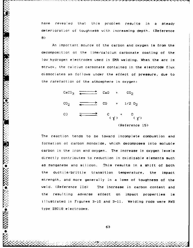
have revealed that this problem results In a steady
N deterioration of toughness with increasing depth. (Reference
8)
An important source of the carbon and oxygen Is from the
decomposition of the lime/calclum carbonate coating of the
low hydrogen electrodes used In SMA welding. When the arc is
strucK, the calcium carbonate contained in the electrode flux
dissociates as follows under the effect of pressure, due to
the rarefaction of the atmosphere in oxygen:
CaC03 ZCaO + CO2
CO2 Z CO + 1/2 02
CO C + 0
(Reference 15)
The reaction tends to be toward Incomplete combustion and
formation of carbon monoxide, which decomposes Into soluble
carbon in the iron and oxygen. The increase In oxygen levels
directly contributes to reduction In oxidizable elements such
* as manganese and silicon. This results In a shift of both
the ductile/brittle transition temperature, the Impact
strength, and more generally In a loss of toughness of the
weld. (Reference lid) The Increase in carbon content and
the resulting adverse effect on Impact properties Is
illustrated in Figures 3-10 and 3-11. Welding rods were AWS
0. type E8018 electrodes.
63
0%

The i ncreased ava IlIabilI It y of ox ygen and n It rogen f rom
the pressurization of the normal atmospheric constituents
only makes the reduction In toughness and elongation and the
- - susceptibility to weld metal cracking worse.
Another Important factor Is hydrogen coming from the
humidity in the enclosure (around 60 to 100%) which can
-. contaminate the electrodes and the weld metal. As previously
stated, under pressure, the liquid Iron or Iron In the gammu'a
phase is able to absorb more hydrogen than at atmospheric
pressure, resulting In a lower cracking threshold In the HAZ
under the weld.
3.6.2 Gas Density Effectp
V The increased gas density as a result of the pressurized
environment, combined with the use of Inert gas for the
ambient environment In the habitat significantly alters the
4.4.4heat-transfer relationships. The magnitude of this change Is
illustrated by the tabulation of selected properties such as
density and transfer coefficients Illustrated In Table 3-2.
.64

.
p.
-S2,C. Cet % % % C .
p0,
'0,2
b % C,,,,
"---- "- 'Comex speial Irods
• j, Common basic rods$
.'
0150 300 m
..
. -. Figure 3-10 Carbon andl Oxygen content in Weld Metal vs Depth(Reference 11)
kgm Comex specil rods i
-. Common basic rods
V I I I -i-
01
0150 300 m
FiguFigure 3-11 Impact Properties vs Depth
(Reference 11)
7S.
' , 65
N N. , .1 -. r . . . . r . , 4 . . ... - .? .- ep-c i, ,-ro d
Commo % ba % rd

%
( DEPTN (FSW)
PROPERTY SURFACE 100 200 300 1 600 1000 10
-lb/FT3
.075 .085 .123 .215 .326 .388
,p"SPLCiri HI IEAT ( E .,1 1 .4 01 .76 .111 0 1 . ).1 67 1 . 168
.. m OVERIALL lHEA'T
. ,TRANSFLR 3.86 34.6 43 .2 74.6 10to. G 117.5 1:jO. b
• " COEFFICIENT
%-," (U¢ SIM!ILAR CONDITION)-. " B U/11R F:T
2 OF
w. COMFOnT 750r 78° F
800F 82°F 850r A70Y Wr°
•CONDITIONS 55%= RHJ 55% R11 55%/ R11l 55% RH 55% Rj; 551 R11 55"1 |tim
. WATER CONTENT OF TIIL=. 'GAS (W) .01086 ,008,1 ? .00610 .00618 .0041 .00291 .00387
, .'-' ],D 1120/LB dry mix
k-V
~. -~
~Table 3-2 Variation of Gas Properties with Depth (Typical)
(Reference 16 )
66
%__ ___60 ___
A~Prr J' SURFAC 100 IN0 30 1000% g%-200P

For considerations given previously, helium basea
atmospheres are usea in most deep hyperbaric welding jobs.
The helium, while it is an Inert bas, has a thermal
conductivity six times greater than air. Studies by
researchers have indicated slightly shorter cooling times in
high pressure helium than in air. This greater cooling has
little effect on HAZ microstructures, but has an effect on
the retention of hydrogen in the HAZ detrimental to weld
quality. The reason the shorter cooling times do not
adversely effect HAZ microstructures is because in the
thickness of metal normally welded, most of the heat flows by
conductivity into the metal rather than by convection into
tne atmosphere. Thus the hardness in the HAZ will be very
close to that measured in welds performed at atmospheric
pressure with the same energy Input. (Reference 15) The
problem remains of the retention of hydrogen in the HAZ. It
is generally acknowledged that the production of structural
quality welds in the underwater environment requires that the
heat input and quench rate be controlled. Such is able to be
accomplished by adjustments in heat input; by variations in
the consumables; and by pre- and postheatling of the metal to
" " be welIed. (Reference 15)
3.6.3 Welding Arc Effects
A welding arc is a sustained electrical discharge
through a high temperature, highly electrically conductive
column of piasma and is produced by relatively large current
67

;1 W7 %- ' 7 V Z_
andl low voltage. Welding ar-cs In air are constricted to some
extent by electromagnetic forces. An underwater welding arc
is additionally compressed by external forces, pressure, and
cooling effects. In order to maintain the rate of current
transfer, core temperatures must Increase. The very high
arc-core temperatures found at greater depths Increase
penetration. For electrode positive SMA welding, more heat
is gradually generated at the electrode tip as depth Is
increased, and less at the cathodic molten pool. The welding
process, in terms of deposition rate, becomes more efficient
with the speed of welding Increasing by as much as 30%.
However, such a weld will be significantly colder than its
atmospheric counterpart. (Reference 6) As depth and- hydrostatic pressure Increase, the current density of the arc
increases and therefore a higher voltage is required to
maintain a constant arc length. (Reference 7)
It has also been observed that the preferred polarity
may change with pressure, i.e. electrode negative GI'A Is
preferred to electrode positive beyond about 7 bars.
Consumable arcs have a substantially higher fall voltage than-~GTA arcs and su most power generation remains at the
electrodes with increasing pressure. Calorimetric tests on
SMA welding have confirmed that process heat transfer
efficiencies are little Influenced by pressure. (Reference 9)
Increasing pressure also causes electrode burn off rates
-~to behave in a complex manner. For electrode positive solidr wire GMA and FCA the burn off Is substantially Independent of
68
A. %

pressure. However, In electrode negative GMA the burnoff
rate fallIs such that the value at 7 bars can be less than
half the normal ambient value. For SMA welding In the
* electrode positive mode, increases In burn off of 30% have
* *been reported over the first 4 bars. This has been
associated with a redistribution In arc heating such that
more power appears at the rod and less at the plate. In
electrode negative GMA welding, behavior can be such that the
burn off Initially Increases reaching a peak between 2 and 3
A,.. bars before falling to a level below that observed under
normal ambient conditions. (Reference 9)
0 The constriction of the arc and of the volumetric shield
surrounding the arc results In a decrease In arc stability.
Because of the reduced arc stability, smaller diameter
welding consumables (generally 2.5 and 3.2 mm) are required
V..for hypeerbaric use than for surface applications. The
effect of residual magnetism in the steel, whether caused by
geophysical effects or induced by machining or grinding,
coupled with the less stable arc often results In magnetic
arc blow. It is frequently necessary to demagnetise before
V root runs are deposited.
3.7 Survey Results
0 A survey was conducted of U.S. actual underwater welding
jobs performed on offshore structures. The survey was
initiated to cover various subjects Including:
69
A

(a) Welding processes and techniques. Which processes
are used: "dry" or "wet"; shielded metal ar-c process or gas
metal ar-c welding? Which techniques are used for butt joints
or fillet joints?
(b) Details of welding procedures. Joint design, degree
of r-estr-aint, residual stresses, preheating temperatures, and
the range of humidity In dry hyperbaric welding.
A total of 89 survey questionaires (see Figures 3-12 and
.4 3-13 for sample cover sheet and questionaire) were sent to
.4 per-sons inter-ested in the field of underwater welding, as
* evidenced by their participation In a conference on the
subject. Survey recipients Included persons In the oil
industry, welding contractors, various research Institutes,
gover-nment regulatory agencies, and academia. Unfortunately,
*most responses contained little Information, as the
- . respondent had had little actual experience In this field.
Many oil companies referred me to their welding contractors.
4..' One oil company considered the Information I was asking to be
proprietary in nature. Of the 89 Initial inquiries, only 10
* substantive replies containing factual and useful Information
regarding underwater welding practices were recieved. These
responses are summarized In this section of the report.
0.0

N Most of the dry hyperbaric welds conducted have been
done in the North Sea. This is in large part because the
regulatory bodies for the offshore platforms (either Lloyds
(British) or Det Norsk Veritas (Norwegian)) almost invariably
require that weloing repairs be done "dry". A consideration
'9 that may have resulted In the above statement is that most
North Sea platforms have carbon equivalent values greater
than 0.40. These carbon equivalent values preclude wet
welding due to predictable joint hardness and low impact
values. Because wet welds, clamps , or other repair methods
* have been shown to be adequate for the repairs conducted In
the Gulf of Mexico, dry hyperbaric welding has not been as
.9. commonly used.
The Minerals Management Service Is the regulatory agency
for the offshore oil and gas industry. Their policy is that
they do not conduct or specify any specific underwater
welcing technique. However, in most Instances, mojor
underwater repair programs must be approved under their
•. Platform Verification Program.
Hyperbaric welding will invariably give better weld
quality results than wet welding. This Is not to say that
. wet welds are bad. A wet weld, properly done can meet all
the strength and integrity requirements that a dry weld can.
It Is just important to know its limitations. A wet weld
will probably be much bigger than the same weld, had it been
73
S2

dlone In the dry. It will probably have a higher degree of
evenly distributed porosity. It will have a harder HAZ, be
less ductile, and Is not suitable for highly stressed Joints
subject to fatigue. The main reason wet welding Is not used
in the Gulf of Mexico is that It is too expensive. The cost
differential between a dry weld and a wet weld to do the same
job has been estimated as between 3:1 to 8:1. If a cheaper
method to conduct repairs exists, that results In a
satisfactory condition, then the cheaper method will
invariably be used. The following rough cost example Is
provided to illustrate the cost differential.
Problem: Repair of offshore structure requiring a
strengthening member be reinforced
Wet weld: 12 inch brace. 5/8 Inch weld. Cost = *20k
solution
Dry weld: 10 inch brace. 1/2 Inch weld. Cost = *65k
solution
The lack of usage of welding In general for the repair
of offshore structrures In the Gulf of Mexica Is evidenced by
the responses to my survey from two offshore oil companies
which said that they had had no underwater welding (wet or
dry) performed on its offshore pipelines and platforms.
Another offshore oil company replied that It had had only one
''V welding job performed on one of Its offshore platforms, and
that It had been done wet.
74
In the words of one respondent to my survey:
"(respondent) typically avoids welding below water.
When adding appurtenances to structures or making
repairs to damaged structural members, we generally
utilize bolt-on clamps. We have found this to be
more cost effective and Just as reliable as
welding."
Another respondent wrote:
1"...hyperbaric welding is not often employed in the
Gulf of Mexico for structural repairs. In fact
(respondent) has not used hyperbaric welding on any
of our 320 structures. Our primary method of
structural repair is wet welding new joint
configurations. Of course the weldment is not as
high quality as can be obtained from hyperbaric
conditions, but with proper design, we can obtain a
joint configuration that can sustain the loading
conditions at a fraction of the cost of hyperbaric
repairs. There is always the possibility that a
situation may arise in the future where hyperbaric
welding may be the most prudent method."
Note: I have subsequently learned that this company is
presently planning a hyperbaric welding Job on an offshore
platform to be conducted at a depth of approximately 600 ft.
75
V6.41 ,2

The structural integrity of the platform was Involved and the
depth of the repair prohibited wet welding.
Depth considerations certainly constrain the use of wet
welding. Wet welding Is usually limited to a depth of
approximately 190 feet. However, one contractor did qualify
a weld to 325 feet in bidding for a contract (only one of
five contractors to do so). Should welding be required below
this limiting depth, it would have to be done in a habitat.
-Respondents to my survey estimate that approximately 80%
of the underwater welding jobs done In the U.S. are conducted
I in the wet. Most of the dry welds are for "hot taps", which
are where one pipeline has to be connected to another
pipline. Structural integrity considerations necessitate a
dry weld. These hot taps have normally been done In
relatively shallow water (approximately 100 ft.)
The welding processes used by most contractors and oil
companies include GTAW, GMAW, FCAW, and SMAW. My sense was
-, that the most popular technique was the GTAW root pass
* followed by the SMAW fill passes. As in the literature
survey, those companies using GTAW didn't use GMAW, and vice
versa. One company indicated that It limited SMAW to depths
J. less than 250 feet.
In personal conversations with some of the survey
respondents, they Indicated only slight changes in the
welding parameters (current and voltage) used during
underwater welding. This was not supported by my research.
*, 76
, , % - - %, -. -, , , -% ,.,,. ,. . .,-, -,., .- .. . ... -. . ,. .-. . . ,... ,

,,- but may be due to the fact that I was welding at higher
pressures than they were used to. Other respondees Indicated
that higher amperages were required.
Those contractors using SMAW for the root pass used 3/32
inch E7016 electrodes for the root pass followed by 1/8 inch
E7018 electrodes for the balance of the passes. GMAW was
used for butt welds by one contractor. GTAW seemed to be the
preferrrential process for the root pass.
The electrodes recommended to me were CHEMTRON and
ATOMIC ARC E7018. These rods proved better than the KOBE
Steel electrodes I had been using with respect to bead
characteristics, but were much worse than the HOBART E7018
electrodes I eventually chose.
One contractor stated that he always used at least
100-150 degree F. preheat to get the moisture off the steel.
He mentioned that in jobs he was familiar with in Mexico.
that they did not use preheat.
Explanations offered for the very erratic arc and weld
4. bead distribution I was getting for the earlier electrodes I
was using were:
(a) oxygen contamination of the shielding gas
(b) incorrect amount of CO 2 in the shielding gas
(c) due to my using pressurized atmosphere Instead of
inert gases, and that I should at least use a cover
gas of Argon.
77
S=°
Contrary to what was said in the literature about not
using nitrogen atmospheres in habitats due to nitrogen
contamination of the welds resulting in severe reductions In
Charpy V energy, two of the contractors I spoke with
Indicated that they routinely used nitrogen as a habitat
* atmosphere. The main reason for using the nitrogen was its
low cost compared to using argon or helium. When questioned
as to the deepest one contractor would use compressed air as
a habitat atmosphere, he replied "about lOOft".
When questioned obout humidity. One respondent
described the humidity condition as a '*dripping wet' 80 to
100% relative humidity. Another respondee Indicated that the
worst case condition of 90% humidity was assumed for welding
" conditions, but that actual humidity conditions were much
less. 1 feel that this would be a direct reflection of the
habitat environmental control system and would vary from
habitat to habitat. The range of responses for humidity
varied from 70 to 95%.
- No respondee gave a factual number for restraint. Those
that did address this subject indicated that the restraint
would be dependent on the geometry of the weld Joint, and
would vary for each specific situation.
OC.
..
O.
K, 78
O-e
"AA A.

po"
IV. METHODOLOGY
* -" The conduct of this thesis required being able to model
the welding conditions experienced when conducting underwater
welding under hyperbaric (dry) conditions. These welding
conditions are routinely experienced when welding repairs are
made to deep sea oil drilling platforms. It became readily
evident that what was required was to design a remotely
operated automatic voltage controlled shielded metal arc
welding device for use In a hyperbaric chamber. The Ocean
d. Engineering Department welding lab already had a hyperbaric
chamber capable of being pressurized to 300 psig. The
remaining materials and equipment had to be procured.
4.1 EauiDment Setup
A general description of the welding setup is as
follows. The desired goal was to conduct stick electrode
welding remotely in a hyperbaric chamber. An automatic arc
length control welding device Is used to control welding
voltage and thus arc length. Although this apparatus Is
* normally utilized for GTAW, by substituting a SMAW electrode
for the tungsten electrode In a specially procured Heliweld
*machine holder, the described equipment can be used to
* properly vertically position the SMAW electrode by
controlling arc length. Motion of the weld bead along the
test samples is accomplished by moving the test sample. A
* variable speed motor carriage attached to a cart fabricated
79
64V% %

to carry the sample was assembled to accomplish this. A
sensor switch can be actuated upon achieving the desired weld
bead length to shut off the welding power supply. (NOTE:
What would be more desirable, would be a gradual lowering of
arc current, but this was not achievable due to malfunctions
in the current equipment.) In practice, the sensor switch
was not normally used, because it was equally easy to just
turn off the power upon observing the arc reach the desired
point at the end of the welding run.
Materials used to complete this project were:
* Jetline Engineering Model ALC 101 Automatic Arc
Length Control welding device
Heliweld Model M50 A Machine holder
Variable speed electric carriage
*Welding sample carriage tray
Pressure chamber
*Pressure chamber extension
*Welding connection to weld head
Ultrasonic humidifier
• Air Compressor
Wet and dry bulb thermometers
Fan
S
Items denoted by an * were manufactured to my
specifications. The welding sample carriage tray was
designed to attach to the variable speed electric carriage.
80
Special accomodations were required to ensure that the tray
was insulated from the pressure chamber and the electric
carriage.
The ALC device is designed to be used with GTA welding.
Thus there ore 3 connections to the welding head: a water
supply, a water return, and the purge gas connection.
-. Current is normally fed not only through the cable sheath of
the water connectors, but using the conductivity of the water
as a medium for electrric current. The setup for this
. experiament did not utilize either the purge gas or the water
connections. In order to ensure an adequate conductive path
. for the current flow, a new connecter was made up of 0 sized
catle to transmit the welding current to the welding head.
The pressure chamber used In this research is 6 feet
(1.8 m) long and 30 inches (76 cm) in diameter. It can be
pressurized up to 300 psig (2070 KN/m 2 ) simulating the water
oepth of 700 feet (210 m). Due to the large size of the
welding apparatus, the pressure chamber required
modification. An extension to the pressure chamber that fit
onto one of the pressure chamber's sight glass windows was
designed and manufactured.
Electrical connections for components internal to the
pressure chamber were made utilizing interface connections
5 esigned into the pressure chamber or pressure chamber
extension.
.1 81

A purge system using argon gas was also devised for use
* y ~with this apparatus. The principle used In this system was
the fact that since argon is heavier than air, all you need
'5-- to do is provide a blanket over the welding arc to provide
*the necessary inert gas atmosphere. Pressure tank
connections existed that were able to be adapted to
accomplish this setup.
As In all experiments, problems arose In utilizing the
N JetlIine Automatic Arc Length Control Welding Device In that
the device's remote and automatic features did not operate as
designed. It was initially desired to set up the welding
sequence such that all operations were automatically executed
once Initial set up and parameters had been established. In
this case, it would have been accomplished by pushing the
Sequence Start pushbutton. Some of the specific problems
with the Jetline Automatic Voltage Control device which
occurred were:
(1) The device was supposed to provide remote contactor
control of the welding power supply to switch on and off
*current from the power supply to the electrode. This
* -' function did not work when connections were made to the
proper amphenol connectors.
(2) A remote switch was to be actuated Inside the
pressure chamber to stop the welding sequence and power
supply. When hooked up to the the proper amphenol
connectors, this feature did not work.
'A 82
%%46

(3) The Sequence Stop push button was supposed to down
slope the curr-ent to the electrode, to avoid forming a crater
at the end of a welding sequence when the current Is abruptly
shut of f, and then to turn of f the motor carr Iage. This
feature did not work.
(4) The Sequence Start Pushbutton was supposed to
automatically sequence the Initiation of the welding arc and
start of welding cart travel . This feature did not work.
(5) The utilization of the Jetline Automatic Arc Length
Control was obviously not the specific use for which It was
intended. Special fitting and weld cables had to be acquired
and attached to permit successful operation. Possibly due to
this "abnormal operation" and "unusual setup", problems arose
with IC chips and transistors, which required troubleshooting
ano replacement.
During one period of abnormal operation, I could only
achieve adequate results by hooking up the connections for
the control of the remote welding power supply to the
incorrect amphenol connectors. However, It was now necessary
* to use the Emergency Sto pushbutton to energi~ze the relay to
provide power to the electrode. The Sequence 5tr
pushbutton now turned off the relay.
I achieved remote shut off of the power supply by
bypassing the amphenol connector and attaching my leads from
% the remotely actuated switch in the pressure chamber directly
83
p.V
n67

-to the Sequence Start pushbutton connections (which now when
actuated would shut off the current to the electrode).
Most of the problems with the JetlIne Automatic Arc
Length control were eventually resolved, however by that
time, I had already decided not to use the automatic start
and stop sequencing functions of the sequence start and stop
switches.
The final configuration provides remote control of SMAW
welding in a hyperbaric chamber. The sequence of operations
required to conduct one pass of welding Inside the chamber
is:
(1) Grind the tip of a new electrode to a fine pointed
tip and insert the electrode into the electrode holder.
(2) Position the cart and workplece below the
. el.ectrode. Attach the ground to the workpiece. Clamp the
workpiece to the cart. Ensure the workplece is properlyC-
aligned oy running the cart back and forth under the
electrode tip several times.
(3) Position the remote switch to turn off the power
"C supply at the end of the desired weld run. (optional) Turn
off the external power supply switch to the motor carriage.
Select the proper speed and direction of motor carriage run
using the variable speed rheostat and direction switch on the
motor carriage.
44 (4) Close the pressure chamber door and pressurize the
chamber.
84
.4'
V
(5) Position the floodlight at one of the viewports to
observe the interior of the pressure chamber.
(6) Turn on the fan to circulate air past the wet bulb
thermometer. When the temperature stabilizes, observe and
record the wet and dry bulb thermometer readings. Record
- - relative humidity. Operate ultrasoonic humidifier as
necessary to obtain the desired humidity.
(7) Turn on the control box.
(8) Set all controls on control box and welding supply
to the desired settings.
(9) Ensure remote switch for the power supply Is off0* and turn on the welding power supply.
- (10) Vertically position electrode near the workpiece
": surface using the touch retract feature of the control box.
(11) Verify all conditions are established.
(12) Start an arc by positioning the remote switch for
the power supply to 'on'.
(13) When an arc is established, start the cart to move
the weld bead down the workplece surface by turning on the
external to the pressure chamber carriage power supply
switch.
(14) When the arc is extinguished, stop the cart.
Upon observing that the workplece has reached the point
where the welding rod Is at the end of the desired weld bead0i.
85
0
'%V

-~~~~- - - - - - ---W -77~W J . W
run, turn off the welding power supply by using the remote
switch for the power supply, and the cart by using the
external carriage power supply switch.
(16) Deenerglze the welding power supply and control
box.
(17) Depressurize the pressure chamber, open the door
and remove the welded sample.
A significant factor In the conduct of this thesis was
p. the large amount of time required to conduct welding runs at
'p pressure. Access to the pressure chamber Is through a large
*swing out door that is secured using 30 one inch bolts.
These bolts had to be properly positioned and then washers
and nuts manually secured or loosened using a large and
unwieldy impact wrench. This process was minimally improved
by using a counterweight and pully system to offset some of
the weight of the Impact wrench. This part of the thesis was
truly tedious, dirty, obnoxious and very time consuming.
Even when proficiency was gained In bolting and unbolting,
thirty to forty minutes were required to complete a bolting
*and unbolting sequence. Raising the pressure Inside the
chamber to 100/200 psig required an additional 30 to 60
minutes. This long process time to just attempt to conduct
* one welding run was the main reason why more data or more
type samples were not conducted.
86
P L' . . 0 . . . .~ .p .

-- -. -. J -. --- P- .P - . -. -.7 -. --. '~-;-
4.2 Parameter Selection
The vast majority of time spent on this thesis was In
determining the correct methodology, parameters, and
consumables required to obtain adequate results. This
section will describe some of the attempts at achieving
satisfactory results that were conducted. Hopefully this
will benefit those Individuals that follow me, and save them
some efforts from repeating my mistakes.
4.2.1 StrIkIna a Welding Arc
* Since the apparatus used In this thesis was operated
remotely, the manual dexterity afforded by an Individual
holding a welding rod and performing the Intelligence based
actions required to strike a welding arc were not available.
4It was readily apparent that some consistent mechanism of
striking an arc was required. To conduct the laborious and
time consuming process of equipment setup and chamber
pressurization, onlIy to f ind out that an arc coulId not be
established would be very frustrating.
It was first attempted to use the touch retract feature
*of the automatic voltage control device to simulate the
dynamic actions of a welder touching and then quickly
*retracting the electrode to establish an arc. This method
worked some of the times, but was deemed too unreliable andVinconsistent. The touch retract mechanism was probably too
* 87

slow In retracting, and the contact phase was excessive,
enabling short circuit conditions to exist for too long.
It was then attempted to place the electrode a fixed
distance from the workpiece. This technique proved
unreliable also, especially at higher pressures.
Steel wool was then placed between the electrode tip and
the workpiece. This worked great at 0 psig, however,
problems arose when going to higher pressures. Equipment
setup and bolting the chamber door shut inevitably resulted
in enough vibrations to cause the steel wool to move away
from the welding electrode tip. Attempts to fix the steel
wool to the tip with tape or glue proved futile. The
attaching device would interfere with the current flow and
subsequently the arc starting mechanism. Instead of
generating an arc at the tip of the rod, the attaching
material would burn. After the material had burnt through,
if the geometry of the welding rod tip with the workpiece was
satisfactory, a new impulse of current would result in arc
initiation.
It was finally discovered that if the electrode rod tip0
were ground to a fine point, the workpiece surface oxide
coating was removed, and the correct separation distance
- between the tip and the workplece was established, that arc
initiation would occur every time (provided, of course, that
adequate amperage was provided).
'
88
Sr% %.M %

4.2.2 Sensitivity Control
The sensitivity mechanism on the Arc Length Control
(ALC) device controls how fast the ALC drive will respond to
an arc voltage fluctuation or change. Having the sensitivity
too high would result in overreaction to voltage
fluctuations. Since these volltage fluctuations would
normally occur on the high side, it would cause the rod to
drive down into the weld pool. A setting of 'one' was
-,. finally decided on.
0 4.2.3 Touch Retract Control
IWThe touch retract mechanism operates to properly
position the torch electrode the proper vertical distance
from the workpiece. It operates by sensing when the
electrode comes into contact with the workpiece. The ALC
drive will then reverse itself for a period of time dictated
by the "touch retract" timer setting. Proper prepositioning
of the touch retract mechanism was essential to get arc
initiation. Having the electrode too far away would result
in no arc initiation. Having the electrode too close would
often times result in a very short lived arc, as the arc
would start, but would extinguish Itself as the rod would
stick to the baseplate. The optimum touch retract setting
varied with different surface geometries, I.e., under the
same welding conditions of pressure, amperage and voltage -
89
'... . .~ . .5 . . . . . . . . ~. . . *. .~.

the touch retract setting would vary between welding on a
flat plate, Lehigh specimen, or Tekken specimen.
4.2.4 Voltage SettinQ
N The voltage setting controlled the welding arc length.
While it was desirable to have a short arc length for arc
stability considerations, having the setting too low resulted
In the rod sticking to the plate before completion of the
welding run. Having the voltage setting too high would
result In too long an arc. At high pressures, this would
result in excessive arc Instability and arc wandering.
* Voltages would actually vary from within approximately 1
volt below the setting to up to 8 volts above the setting.
If voltages ever exceeded the setting by "6" volts, the
automatic arc length controller was supposed to cut off power
to the electrode because it thought that It sensed a
'burn- through" condition. A setting of approximately 23
volts was finally established as a workable setting. This
setting sometimes had to be varied up to 0.5 volts to
establish welding conditions that would result In an
acceptible weld. It was noted that voltage fluctuations were
generally more severe at high pressure conditions.
4.2.5 Amerage Control
Amperage control was adjusted to provide the best weld
bead geometry, i.e., surface shape and characteristics, depth
of penetration, bead width, etc. It was discovered that the
90

manufacturer's suggested parameter of approximately 160 amps
could not be adhered to at high pressure conditions. Very
high amperages were necessary to Initiate and sustain the arc
Control of volts and amps was regulated to obtain a
- satisfactory bead. While it would have been desirable to
- have a constant heat Input for all welding conditions, and
vary voltage and amperage to obtain this condition, this
proved not to be practical. The voltage and current setting
was completely predicated on having an acceptable weld bead.
At high pressure conditions, this was acomplished by
obtaining a voltage setting that would work with the highest
amperage avaIlable.
4.2.6 Start Adjust Setting
The start adjust control on the welding power source
permits the operator to select an amperage setting for arc
initiationo which Is different from the setting of the steady
state amperage control. The starting current which is
selected is In effect for the first 35 to 40 ccycles of the
welb. After this time period, the weld current will go to
* the setting of the steady state amperage control.
It was found to be necessary to use a setting of 10 on
the start adjust control dial. Use of lower settings did not
*. provide as reliable results for Initiating the welding arc.
This resulted in the initiating arc current being 300 amps.
,d.
91.%
0.

4.2.7 Welding Soeed
Arc travel was accompi ishei by moving the workplece
under the stationary welding rod. Slower speeds than the
manufacturer's recomended parameter were generally found to
provide better weld bead penetration. Acceptable weld bead
characteristics were obtained by using a speed of 7 inches
per minute for all welding runs.
4.2.8 Electrode Bakino
The welding rods used were 1/8 inch (3.2 mm) Hobart AWS
-7018 electrode, which is a low hydrogen rod of a type
commonly used for hyperbaric applications. Most low hydrogen
roas specify a baking time for the rods to get rid of excess
moisture. This should be followed by rapid use of the rods
upon removal from the oven. This bake period was not
utilized for these rods because it was not felt that the high
humidity conditions present, in conjunction with the long
delay times in setting up the apparatus and in establishing
the desired welding conditions (45 - 75 minutes) would negate
the beneficial aspects of baking the rods In an oven.
4.2.9 Preheat
Preheating of the workpiece was not conducted for two
* reasons. Worst case conditions that would most likely
-. promote cracking were desired. In addition, the large
p, electrical requirements of heaters could not be sustained
92
% .. :

i . . . - - " . . 9 - - . - -- - $
through the existing pressure tight connections of the
pressure chamber.
4.2.10 Final Settings
Manuf.
recom Opsig lOOpsig 200psig
Amps 150 220 280 280
Volts short arc lgth 22.8 21.6 22.4
touch 2 2 2retractSensi- 1 1 1tivityArc (in/min) 7 7 7travelStart 10 10 10adjust
4.3 Atmosphere
Atmosphere containing the normal percentages of oxygen,
nitrogen, hydrogen, etc. was used In the welding chamber at 0
psig and for pressurization to higher pressures. The main
reason for this decision was for convenience. Under normal
offshore platform welding conditions, normal atmosphere is
S only used down to welding environments of around 100 to 150
feet below sea level (70 psig maximum). This is to prevent
a highly flammable situation arising from the raising of the
partial pressures of oxygen by pressurization and the
contamination of the weldment with oxygen and nitrogen.
Deeper than this depth, inert gas environments are used.
.1 Since the welding chamber used In this research was to be
93
'SO IV N .I- 'w "

unmanned, and the effect of oxygen and nitrogen contamination
would minimally, if any, affect the outcome of the research,
it was decided to only use normal atmosphere for pressurizing
the pressure chamber. It would have been extremely expensive
to provide an Inert atmosphere of heliox or argonox, even if
a reclamation system could have been procured or developed.
A local purge system utilizing argon gas that would blanket
the weld was fabricated, but not used, as acceptable welds
were obtained without its use.
The high flammability of the pressurized atmosphere
actualy caused several problems during experimentation. In
one instance, while at 200 psig, a spark landed on a teflon
attachment to the sample cart and Immediately caused the
teflon to start burning. Rapid depressurization of the
chamber to remove excess oxygen was insufficient to prevent
complete incineration of the teflon piece. At 0 psig, the
teflon piece had been totally immune to many welding sparks.
Thereafter, copper sheets were placed over all plastic, wood,
or otherwise flammable pieces in the pressure chamber to
.4 prevent this incident from recurring.
4.4 Humidt
V" One of the unavoidable problems associated with
7 underwater welding under hyperbaric conditions is the
presence of humidity. The exact amount ot humidity to be
dealt with varies with the individual habitat system and Its
94
A '''' ' :' '''"" . , '- - "- . " , - , - , ', . . . .. . . . , •.. . , , . . . . . . . . . . . - . - - . , -0 - , - , , % ,. % " , ' . . . % . -"%' . - , o - - . . o . . , . .. . . . . , . . ,

ability to control the environment, but has been estimated as
being from 60 to 100%. Discussions with an underwater
welding consultant indicates that the humidity conditions are
"dripping wet". The humidity conditions I selected were:Ad
dry: the ambient humidity conditions in the welding
laboratory
humid: 100% humidity as Indicated by equal readings
on the wet and dry bulb thermometers in the
welding chamber
wet: in addition to 100% humidity, the humidifier
was left on for ten minutes. This created a
condition where the ultrasonic humidifier was
emitting a fine water mist, but where the air
could not accept any more moisture. The water
is forced to fall on the surfaces of the
welding chamber interior.
An ultrasonic humidifier was used to help establish
humidity conditions. At 0 psig, It was used to obtain the
100% humidity condition. At 100 and 200 psig, the 100%
humidity condition was automatically established through the
just completed pressurization of the atmosphere. Since the
compressed air is less able on a percentage basis to retain
moisture than at 0 psig, pressurization of air will
inevitably lead to achieving a 100% relative humidity
condition. Any subsequent pressurization results in
95

condensation of excess water in the air. Should I have
desired to establish a lower humidity condition at pressure,
I would have been forced to wait extremely long times for the
. humidity to reach an equilibrium condition for the existing
* temperature and pressure. An alternative approach would have
. been to dry the tank by some means (dessicant or heaters). I
elected not to do either of these options and just used 100%
humidity at hyperbaric pressures. At 100 and 200 psig, the
humidifier was used to establish the wet conditions desired.
4.5 Pressure Settings
It was originally Intended to utilize the maximum
capabilities of rhe pressure chamber and weld at 3 pressures
- 0, 150, and 300 psig. However, while conducting studies to
ascertain the optimum welding condition at high pressures, it
was found that 200 psig was the maximum pressure that an arc
could be established and sustained with the existing
equipment. At pressures only minimally greater than 200
psig, i.e. 225 psig. either an arc could not be established,
or arc initiation would be Immediately followed by the arc
going out, for reasons I could not ascertain. Upon lowering
'- the pressure to 200 psig, and depending on the condition of
the welding rod tip, a welding arc could be successfully
established. It was therefore decided to Just weld at 0,
100, and 200 psig. (Note: an option not fully explored would
have been to use a smaller diameter welding electrode.)S
96
%'S%

4.6 Selection of Welding Rods
The process of selecting an appropriate welding rod to
conduct this thesis with took up the largest number of
manhours in the conduct of this thesis. The type of welding
rod supplied by the sponsors of this thesis was a Kobe Steel
manufactured low hydrogen type rod designated LB-52UL. This
welding rod was originally supplied In 5/32 and 1/4 Inch
diameters. Field experience related to me through the
literature search and correspondence resulting from the
questionaire I had sent out Indicated that as a minimum,
obtaining satisfactory welds would probably require even
smaller electrodes. It was then requested that Kobe Steel
supply 1/8 in (3.2 mm) electrodes, which they readily
complied with. This size electrode was the type eventually
used in the study.
The long time spent in welding rod selection was
gainfully employed in gaining proficiency on the apparatus
and in the optimization of welding parameters. Once at.
d suitable roc was found, the experience gained in welding at
high pressures allowed rapid selection of optimum welding
parameters.
a,
4.6.1 Initial Attempts
Initial attempts to conduct high pressure welds were
accomplished using the LB-52UL rods supppl led by Kobe Steel.
Problems encountered included arc initiation, sustaining the
9'%p

- J9 5 CK E NDANISO ETANDMLSI INSTRENGTH LOU ALLOY STEELS (U) MASSACHUSETTS [MST OFTECH CAMBRIDGE DEPT OF OCEAN ENGINiEERIN R MI JUN 8?
AUNICLASS1FIEI NM228-85-G-1262 F/G it/6. UL
.ENOEOEE
1.4..
132l
MICROCOPY RESOLUTION IEST CHART
Iw- ., - " , " - -

arc, and Irregular weld bead profile. Significant amounts of
% I time were spent In establishing the optimum electrode tip
relationship with respect to the sample and welding
parameters to achieve the most satisfactory weld possible.
However, the problem of minimizing the weld bead
Irregularities continued to plague these efforts.
Significant amounts of time were spent In varying and
rechecking voltage, amperage, arc travel speed, and
sensitivity In attempts to reduce weld bead irregularities.
4.6.2 Description of Weld Bead Irreaularities
Significant weld bead Irregularities resulted from using
all welding rods at high pressure with the exception of the
Hobart 7018 electrodes. The resultant weld bead surface
profile would have very inconsistent and erratic weld
deposition patterns, and numerous ridges, giving the
appearance of a 'cold weld'. The weld deposition rate was
very irregular. Even though the workplece was passing
underneath the welding rod at constant speed, the weld
deposition rate would cyclically raise and lower, resulting
* In areas of the weld bead where weld metal deposits were much
greater than in other areas, aand areas where the weld
aeposit was very sparse. The effect of having a very erratic
welding arc at high pressures was also reflected In the fact
that the point of maximum deposition rate was not always In
the center of the weld bead. The result was a very Irregular
shaped weld bead, as if the welding was done manually by a
98
N .P . P0A 0"
-~ person who had an unsteady hand resulting In inconsistent
welding speed and a wavering from side to side. The cyclic
nature of the raising and lowering of the weld deposition
rate or the wandering of the maximum weld deposition rate
from side to side was very erratic and of no discernable
per Iod.
4.6.3 Weldmng Rod Search
Consultations with Kobe Steel revealed that Kobe Steel
was not constraining the research to using the LB-52UL
electrode that they had provided. Indeed, this particular
* type electrode had had no hyperbaric welding experience. The
v literature on the subject notes that the welding consumable
-N. plays an important part In obtaining satisfactory welds at
high pressure. Many of the private contractors who conduct
hyperbaric underwater welding are reported to utilize their
own proprietary consumables. While It was highly unlikely
that I would be able to gain access to these proprietary
consumables, I endeavored to gain more Information on the
mechanics of conducting underwater welds and to determine
0 exactly which "off the shelf" electrodes, If any were being
used in the field.
In conversations with several consultants In the field
* of underwater welding, I was able to learn that:
(1) Higher amperages were required to conduct welding at
high pressures. This was consistent with my experience of
having to use amperages higher than the manufacturer's
S 99

recomendations. One consultant did relate to me that his
company had found = change of welding parameters was
necessary clown to 132 ft (59 psig). While my experience did
not verify this fact, It did not counter It because the
pressures I was dealing with were much higher.
(2) Welding consumables do play an important part in
obtaining satisfactory hyperbaric underwater welds, but it
was not uncommon to use off the shelf electrodes in
pelo-irg riypero.-a' tjrnerw. tar wp.l . .. Wel~dr expertise and
,.
. i L U 'i i c L1U. if:.. . f.1,'A: iai C;? 1.1;) ini ..t U IULnLLiL LL Ve I
*situation. I was provided with the types of welding rods
that they had had positive experiences with (Chemtron and
Atomic Arc 7018).
The importance of having the proper consumable is also
evidenced by another example. Some of the trial runs at
pressure were conducted with an Easy-Arc 7014 electrode.
While no problems with arc-initiation occurred, as expected
due to the 7014's iron content in the coating, the resultant
weld bead exhibited severe porosity. This porosity can be
attributed to the insufficient amount of protective vapor
generated from the welding rod coating during welding at high
pressures.
100
r A N

W4 V. " . 0
The following rods were obtained and tested to determine
the welding rod which would exhibit the best high pressure
welding characteristics.
electrode tyre diameter (mm)
LB-52UL 3.2
'L LB-52UL 4.0
LBM-52 3.2
LB-52UL 3.2 (0.2 mm smaller diameter
flux coating)-,..,
LB-52UL 3.2 (0. 4 mm smaller diameter
flux coating)
Atomic Arc 3.2
7018
Airco 3.2
7018
Lincoln 3.2
7018
Hobart 3.2
7018
All rods except the Hobart rod exhibited varying degrees
of weld bead surface irregularities when welded at high
pressure. The Atomic Arc and Airco rods had somewhat better
characteristics than the other rods. The Hobart 7018 rod's
weld bead profile, when welded at high pressure, In marked
contrast to the above, was exemplary in all respects. It wasS.'
101
e6
%' " % %,% %% %%, % ,5 " % , - %
uniformly deposited and had a surface and crossectional
profile that could not readily be distinguished from the weld
bead profile of a weld conducted at 0 psig.
4.6.4 Observations on Weldina and Arc Stability
The literature and conversations with welding
consultants indicated that because of increasing arc
instability at high pressures, both a smaller diameter
welding rod, and a shorter arc lengths were required to
obtain satisfactory welds. These observations were found to
be true during the conduct of this thesis.
Observations of arc stability and resultant weld bead
profiles indicated that arc stability was a function of."
,., consumable, arc length, amperage, and electrode diameter.
Arc stability could be enhanced by: (1) decreasing the
diameter of the weld rod, (2) Increasing the amperage, (3)
decreasing the arc length.
Excessive arc Instability caused voltage fluctuations
that could cause the arc to extinguish either through the ALC
sensing a burn through condition or from other
considerations. On numerous occasions under hyperbaric
conditions, the arc would just go out. The reason Is
. unclear, but could possibly be attributed to excessive arc
instability. Of course, once the arc went out, a glob of flux
5. would form over the electrode tip and prevent a subsequent
arc initiation.
102
V6

Another phenomena that was observed was that at high
pressures with the LB-52UL rod, almost globular transfer
seemed to occur, whereas at 0 psig spray transfer occurred.
Probably the most perplexing phenomena that occurred
during high pressure welds was that the rod seemed to stc
in the weld pool. Motion of the constant speed cart and
workpiece under the stationary electrode was easily
distinguishable. On some occasions, the rod seemed to stick
in the weld pool, as observed by the supposedly stationary
electrode and arc moving slightly. The welding rod and arc
would be observed to jump or spring back to the original
position when the cart had moved the workpiece a sufficient
distance for the bending weld rod to generate enough spring
force to overcome whatever was causing the arc and welding
rod to stick to the workpiece. On the occasions when this
did occur, I raised the set voltage, which Increased the
* welding ar-c length. This appeared to solve the problem.
It is interesting to note that the welding rod
recommended to me by a consultant In underwater welding
practices was not the ultimate welding rod selected by me In
this thesis. While the welding rods recommended by him
(Atomic Arc or Chemtron E7018) had superior weld bead
profiles and cross sectional characteristics than the
previous rods tested, they still exhibited significant
surface irregularities and Inconsistent weld deposition
rates. The weld bead characterisics of the Hobart E7018 rod
103
%06

were vastly suuperior to any of the other rods tested and had
weld bead characteristics at high pressure almost exactly
similar to a 0 psig weld.
This may be indicative of the fact that while for the
purposes of this thesis, the Hobart E7018 rod was vastly
superior, in the field, with the aid af a skilled welder, the
other rods tested might serve equally as well. The price you
would pay in the field by using the other welding rods would
be that the welder would have to be a better welder and be
more attentive to controlling his rod travel to compensate
for the irregularities exhibited by the other rods. A key0
difference in the manner in which this thesis' apparatus was
set up is that I was not able to Introduce the manual
dexterity of a welder in obtaining satisfactory welds.
4.7 Methodologv Summary
As a result of the above observations, it was decided to
utilize the 3.2 mm Hobart E7018 electrode at a very high
amperage (190 amps) when welding at high pressures. Welding
was conoucted at three pressures: 0 psig, 100 psig (68.5m
* depth) and 200 psig (137m depth). 100% re;ative humidities
were used at all pressures for comparisons. At 0 psig,
welding would also be conducted at the welding laboratory
ambient humidity. A "wet" condition would be also evaluated
to see how extreme moisture conditions would effect weld
cracKing. No preheat would be used in any welding. Normal
*atmosphere would be used for pressurization.
104
%6e

I.
4.8 Data and Results
This section will provide the testing parameters and
results from the conduct of this research on hyperbaric
welding. Table 4-1 provides the environmental and welding
parameters used. Table 4-2 provides the results of the
. Lehigh cracking tests. Where cracking occurred, the degree
"V of cracking is indicated by using the cracking ratio, which
Is the ratio of the crack length as compared to the weld
depth. (see Figure 4-1) The Lehigh test is most useful in
evaluating electrodes because cracking occurs In the weld
- metal. The cracking in these Lehigh tests occurred
predominately in the weld metal, but also occurred in the
HAZ, to varying degrees in the different metals. This
indicates that the base metals are evaluated with the Lehigh
test.J,
Cra~kin@Crack
H-X H
Figure 4-1 Determination of a Cracking Ratio
(Reference 12)
105
.

W V W
Using the analytical/empirical system for preventing
cold cracking An steel weldments presented In Section 14.33
of Reference 1, calculation of cracking sensitivity, critical
cooling times and preheat required were conducted for the
steels and pressures. Preheat requirements are tabulated in
Table 4-2. These results indicate that preheat should have
been applied to the Type II steel to prevent cracking. This
was not done, yet no cracking occurred. This substantiates
that the system presented to prevent cracking may not be
totally applicable to the low carbon equivalent steels, such
* as the Type II and III steels used In this thesis. This
conjecture has been presented earlier by Reference 5.
The test results generally substantiate that the lower
the cracking sensitivity, the more resistant the steel is to
hydrogen cold cracking. The Type I steel, which had the
highest carbon equivalent values and cracking sensitivity
values, had cracking under all pressures and humidity
conditions except for the dry atmosphere at 0 psig.
The Type II steel did not sustain any cracking at any
* pressures at 100% humidity. The Type III steel (with the
lowest cracking sensitivity) only had one crack over the test
range pressures at 100% humidity. This occurred at 200 psig
* . A check sample, welded at 200 psig and 100% humidity,
however did not sustain any cracking.
Both Type II and Type III samples, welded under "wet"
conditions at 100 psig, sustained cracking. This might be
106
. .6I% N
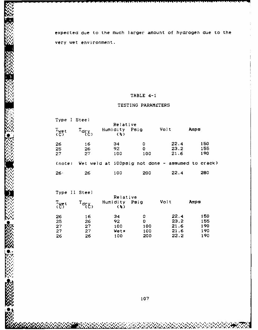
expected due to the much larger amount of hydrogen clue to the
very wet environment.
TABLE 4-1
TESTING PARAMETERS
Type I SteelRelative
Twet Tdr Humidity Psig Volt Amps
26 16 34 0 22.4 150w- "25 26 92 0 23.2 155
27 27 100 100 21.6 190
(note: Wet weld at 100psig not done - assumed to crack)
26. 26 100 200 22.4 280
.-. \p
Type II SteelRelative
Twet Tdrv Humidity Psig Volt Amps- (C) (C) (%
26 16 34 0 22.4 15025 26 92 0 23.2 15527 27 100 100 21.6 19027 27 Wet* 100 21.6 19026 26 100 200 22.2 190
I.10
~107

TABLE 4-1 (cont)
TESTING PARAMETERS
Type III SteelRelative
Twet Tdr Humidity Psig Volt Amps(C)--
-' 26 16 34 0 22.4 15025 26 92 0 23.2 15527 27 100 100 22.2 19027 27 Wet* 100 21.6 19026 26 100 200 22.2 190
' 26 26 100 200 22.4 190
NOTE: For all runs:* Welding electrode: 1/8 In. (3.2mm) Hobart E7018
Touch retract: 2Start adjust: 10Cart travel: 7 In/minSensitivity: 1HF start: ON
L 108
'e.
NV' , -. y. ]i # . .- , t.; . "' -.-.-. -. ...-.. . ..-. .

.%,
Table 4-2
LEHIGH CRACKING RESULTS
Tested Steel: Type I (PCM = 0.228, C.E. = 0.373)
Calc Crack- Pres- Humid- Sectioning LocationsPre- ing sure ityheat Expect. (psig) (%) Start Middle End(C)NR N 0 34 N.C. N.C. N.C.50 Y 0 92 CR =100%
Complete break
122 Y 100 100 CR = 20% CR = 20% N.C.loc = HAZ loc = HAZ
138 Y 200 100 CR = 100%Complete break
Tested Steel: Type II (PCM = 0.193, C.E. = 0.315)
Calc Crack- Pres- Humid- Sectioning LocationsPre- ing sure ityheat Expect. (psig) (%) Start Middle End(C)NR N 0 34 N.C. N.C. N.C.NR N 0 92 N.C. N.C. N.C.44 Y 100 100 N.C. N.C. N.C.-- -- 100 WET CR=100% CR=100% CR=-100%81 Y 200 100 N.C. N.C. N.C.
Tested Steel: Type III (PCM = 0.154, C.E. = 0.292)
Calc Crack- Pres- Humid- Sectioning Locations
Pre- ing sure ity
heat Expect. (psig) (%) Start Middle End
NR N 0 34 N.C. N.C. N.C.NR N 0 92 N.C. N.C. N.C.NR N 100 100 N.C. N.C. N.C... .. 100 WET CR=15% CR=50% CR=-100%NR N 200 100 N.C. N.C. CR=25%NR N 200 100 N.C. N.C. N.C.
NR = Not RequiredN.C. = No cracking detectedCR = Cracking Ratio
10
109

V. CONCLUSIONS
1. Emulation of the underwater conditions experienced in
underwater hyperbaric welding using the SMA welding technique
was effectively conducted using the welding and simulation
apparatus described In this thesis. Deviations from actual
welding conditions involved those aspects of the welding
sequence which could not use the facilities and capabilities
of an intelligent and skilled welder, I.e., the manual
dexterity of the welder, and the facility of the welder to
execute procedures to minimize the welding electrode from
excessive exposure to the humid environment. The normal
inert gas Heliox environment was also not utilized, for
economical reasons, however this capability certainly can be
Incorporated into the apparatus.
2. Welding under hyperbaric conditions will have an adverse
effect on the hydrogen crackIng of high strength steels due
to a combination of the following major effects:
A. As pressure Increases, for the same relative
humidity, the water content of the atmosphere becomes
greater, thus providing a larger source of hydrogen to enter
the weld pool and be absorbed into the welding electrode.
-A
*" B. As pressure increases, when welding In a compressed
*normal atmosphere composition, the partial pressure of
110
%
J
hydrogen increases, thus providing an increased source of
hydrogen to enter the weld pool.
C. As pressure Increases the solubility of hydrogen
into the weld pool increases.
D. For purposes of hydrogen cracking control, it would
be desirable to use a high heat input process. However, the
adverse effect of pressure increases on welding arc
characteristics, and the resultant effect on the weldinga.
parameters necessary to achieve satisfactory welding
conditions, results in a relatively low heat input process
due to the small electrodes used.
3. Consistent with the theories pertaining to the
determination of cracking susceptibility Pw and the
prevention of hydrogen cold cracking: as the quality of HSLA
steel increases, i.e., as PCM or C.E. lowers for a constant
yield strength, the steel's resistance to hydrogen cold
cracking Improves. Use of low Pcm steels In underwater
structures will facilitate repairs conducted under hyperbaric
* conditions due to their decreased susceptibility to hydrogen
cold cracking. It Is significaant to note that for the
, adverse welding conditions existing in the tank, I.e. no
humidity or electrode control, no preheat or post heat, etc.,
that no preheat was required for the Type III HSLA by
analytical calculation, and that essentially no cracking was
experienced for the HSLA steels subjected to 100k humidity.
111

dT
Cracking was experienced when subjected to direct moisture,
i.e. "wet" conditions.
4. It is apparent that hyperbaric welding conditions are
inherently detrimental to the prevention of hydrogen cold
cracking. Welding environmental conditions should be
,d controlled to minimize the possibility of hydrogen entering
the weidment, including the maximum use of inert gas shielded
welding methods. Selection of steels with low PCM or C.E.
should also be encouraged to maximize the chances of not
inducing hydrogen cold cracking. HSLA steels satisfy the
* requirement of low PCM (C.E.) with high yield strengths, and
should be favored over high PCM (C.E.) steels for use In
underwater platforms.
5. This study substantiates that the current methods for
preventing cold cracking in steel weldnents may not be
entirely applicable to low Pcm HSLA steels. As presented In
Reference D, current carbon equivalent formulas have
underated a low Pcm (Ceq) steels susceptibility to cold
cracking (i.e., Indicates that preheat is required, when in
actuality, preheat is not required to prevent cracking).
~112
'H%L1 8. -

VI. RECOMENDATIONS
1. To fully employ the cracking susceptibility and cracking
prevention theories presented in the literature, it Is
necessary to be able to predict the resultant hydrogen
content of the weld metal. Under hyperbaric conditions, this
becoomes a dIfficult task, because it is a function of so
many variables, e.g., pressure, weld process used, initial
moisture content of electrode, ambient humidity, exposure
time of electrode to humidity, arc length, purge gas
utilized, etc. Modeling of some of these variables has
already been accomplished. It would be very beneficial to
model more completely the pressure dependent variables
encountered under hyperbaric welding conditions In an
analytical model that could predict hydrogen content of the
weld metal. Once this has been accomplished, comparison of
hyorogen weld cracking susceptibility can be accomplished,
comparing the weld cracking suscrptibillity of similar
materials with the same hydrogen weld content, welded under
different pressures. Differences in cracking susceptibility
would Indicate other pressure dependent variables that affect
the hydrogen weld cracking susceptibility of materials.
2. In view of the difficult time experienced in obtaining asuitable consumable to conduct this thesis, it Is recommended
that studies be conducted to see what effect different
materials and material combinations in the consumables have
113
14P

R. I W- .w. I -I -I r1 .WUW V. W r v- . r - IF ~ T r y p , f
on the welding arc and resultant weld bead characteristics at-"
pressure. This would facilitate further research on
hyperbaric welding using consumables.
. 3. Further research needs to be conducted on determining
applicable equations for carbon equivalents and/or cracking
susceptibility that can accurately determine a low carbon-S
equivalent HSLA steel's need for preheat, postheat, and
cooling off times.
11
%S
-S
%-
--p
I
' 114
Ig

BIBLIOGRAPHY
1. Masabuchi, K., Analysis of Welded Structures, PergamonPress, New York, 1980.
2. Mnushkin, O.S., and Karkhin, V.A., "Calculation ofPreheat Temperature in Preventing Cold Cracking in theWelding of Steel", Svar. Prolz., No. 11, 1980, pp. 4-5.
3. Savage, W.F., Nippes, E.F., and Honuna, H., "HydrogenInduced Cracking In HY-80 Steel Weldments", WeldingResearch Supplement, Nov 1976, pp. 368s to 376s.
4. Montemarano, T.W., Sack, B.P., Gudas, J.P., Vassilaros,M.G., and Vanderveldt, H.H., "High Strength Low AlloySteels In Naval Construction", Journal of ShipProduction, August 1986, pp. 145-162.
5. Sawhill, Jr., J.M., "Welding of HSLA Pipeline Steels",Welding Design and Fabrication, August 1977, pp. 64-67.
6. Cotton, H.C., "Welding Underwater and in the Splash Zone- a Review", Underwater Welding, Conference Proceedingsof International Institute of Welding (IIW), Trondheim,Norway, 27-28 June 1983, Pergamon Press, 1983, pp. 4-48.
7. Masabuchi, K., Gaudiano, A.V., Reynolds, T.J.,"Technologies and Practices of Underwater Welding",Underwater Welding, Conference Proceedings of IIW,Trondheim, Norway, 27-28 June 1983, Pergamon Press,1983, pp. 49-70.
8. Christensen, N., "The Metallurgy of Underwater Welding",Uncerwater Welding, Conference Proceedings of IIW,Trondheim, Norway, 27-28 June 1983, Pergamon Press,1983, pp. 71-94.
9. Allum, C.J., "Effect of Pressure on Arcs", UnderwaterWelding, Conference Proceedings of IIW, Trondheim,Norway, 27-28 June 1983, Pergamon Press, 1983, pp.171-178.
10. Kvaale, P.E., Gjermundsen, K., Christensen, N.,"Moisture Absorbtion of Basic Electrodes Under Pressureup to 33 bar", Underwater Welding, ConferenceProceedings of IIW, Trondheim, Norway, 27-28 June 1983,Pergamon Press, 1983, pp. 277-282.
11. Coriatt, G., "Hyperbaric Welding in the Repair ofOffshore Pipelines and Structures", Underwater Weldingof Offshore Platforms and Pipelines, ConferenceProceedings of American Welding Society (AWS), New
115
% !N

Orleans, La., 5-6 Nov 1980, American Welding Society,1981, pp. 49-67.
12. Masabuchi, K., "Underwater Factors Affecting WeldingMetallurgy", Underwater Welding of Offshore Platformsand Pipelines, Conference Proceedings of AWS, NewOrleans, La., 5-6 Nov 1980, American Welding Society,1981, pp. 81-98.
13. Gaudin, J.P., and Sudreau, B.G., 'Problems Encounteredin Underwater Welding: Facilities Available for theStudy of Certain Parameters in a Simulation Chamber",Underwater Welding of Offshore Platforms and Pipelines,Conference Proceedings of AWS, New Orleans, La., 5-6 Nov1980, American Welding Society, 1981, pp. 155-173.
14. Thomas, W.J.F, "Welded Subsea Structural Repairs in theZ North Sea", Metal Construction, February 1986, pp.a' 85-89.
15. Coriatt, G.M., Bellamy, G.P., "Hyperbaric Welding forConnection and Repair of Deep Sea Pipelines",Proceedings of Offshore Technology Conference, Houston,Tx., 8-11 May 1978, Offshore Technology Conference,1978, pp. 2601-2609.
16. Delaune, Jr., P.T., "On-site Welded Repairs to OffshoreStructures Using Dry Underwater Habitats", Proceedingsof Offshore Technology Conference, Houston, Tx., 8-11May 1978, Offshore Technology Conference, 1978, pp.2571-2579.
17. Tanaka, T, "Four Stages of the ThermomechanicalProcessing in HSLA Steel".
18. Ouchl, C., "Accelerated Cooling after Controlled Rollingin HSLA Steels".
19. May, I.L., Schetky, L.M., Klschnadev, M.R., "The Role of* Copper in HSLA Steels, a Review and Update".
20. DeArdo, A.J., "Ferrite Formation from ThermomechanicallyProcessed Austenitic HSLA Steels".
21. Henderson, I.D., "Narrow Gap Welding - A Process forJoining HSLA Steels".
22. Bufalini, P., et.al., "Accelerated Cooling after ControlRolling for Linepipe Production".
116
23. Jones. B. L., "Advances I n All Ioy DevelIopment and ProcessTechnology In the Production of High-Strength LinepipeSteel11
24. De Gaspari, "Shipbuilding Materials", MarineEngineering/Log, October 1983.
25. Hillenbrand, 111, F.F., "Research on High-StrengthSteels with an Improved Resistance Against Cracking",M.S. Thesis, MIT, June 1984.
26. PurcellI, M.J. , ' Hydrogen- Induced Cracking In Three HighStrength Steels', M.S. Thesis, MIT, August 1984.
911
S.4
M,
oz
ow
% %%

I4'1
-U I1%
FI
/LtV1U~D9
I II
04 0 0 0 0 0 S 0 0 0 0 0 0 0 0 0 0~~ .~ ,~