Inspection of Penstocks and Featureless Tunnel-like ... · Inspection of Penstocks and Featureless...
14
Inspection of Penstocks and Featureless Tunnel-like Environments using Micro UAVs Tolga ¨ Ozaslan, Shaojie Shen, Yash Mulgaonkar, Nathan Michael and Vijay Kumar Abstract Micro UAVs are receiving a great deal of attention in many diverse ap- plications. In this paper, we are interested in a unique application, surveillance for maintenance of large infrastructure assets such as dams and penstocks, where the goal is to periodically inspect and map the structure to detect features that might indicate the potential for failures. Availability of architecture drawings of these con- structions makes the mapping problem easier. However large buildings with fea- tureless geometries pose a significant problem since it is difficult to design a robust localization algorithm for inspection operations. In this paper we show how a small quadrotor equipped with minimal sensors can be used for inspection of tunnel-like environments such as seen in dam penstocks. Penstocks in particular lack features and do not provide adequate structure for robot localization, especially along the tunnel axis. We develop a Rao-Blackwellized particle filter based localization al- gorithm which uses a derivative of the ICP for integrating laser measurements and IMU for short-to-medium range pose estimation. To our knowledge, this is the only study in the literature focusing on localization and autonomous control of a UAV in 3-D, featureless tunnel-like environments. We show the success of our work with results from real experiments. 1 Introduction Recently, micro UAVs have attracted significant attention in a variety of civilian applications due to their low cost and superior mobility. One possible application is Tolga ¨ Ozaslan, Shaojie Shen, Yash Mulgaonkar and Vijay Kumar University of Pennsylvania, 19104, Philadelphia, PA, Nathan Michael Carnegie Mellon University, 15213, Pittsburgh, PA, e-mail: {ozaslan}{shaojie}{yashm}{kumar}@seas.upenn.edu,nmichael@ cmu.edu 1
Transcript of Inspection of Penstocks and Featureless Tunnel-like ... · Inspection of Penstocks and Featureless...

Inspection of Penstocks and FeaturelessTunnel-like Environments using Micro UAVs
Tolga Ozaslan, Shaojie Shen, Yash Mulgaonkar, Nathan Michael and Vijay Kumar
Abstract Micro UAVs are receiving a great deal of attention in many diverse ap-plications. In this paper, we are interested in a unique application, surveillance formaintenance of large infrastructure assets such as dams and penstocks, where thegoal is to periodically inspect and map the structure to detect features that mightindicate the potential for failures. Availability of architecture drawings of these con-structions makes the mapping problem easier. However large buildings with fea-tureless geometries pose a significant problem since it is difficult to design a robustlocalization algorithm for inspection operations. In this paper we show how a smallquadrotor equipped with minimal sensors can be used for inspection of tunnel-likeenvironments such as seen in dam penstocks. Penstocks in particular lack featuresand do not provide adequate structure for robot localization, especially along thetunnel axis. We develop a Rao-Blackwellized particle filter based localization al-gorithm which uses a derivative of the ICP for integrating laser measurements andIMU for short-to-medium range pose estimation. To our knowledge, this is the onlystudy in the literature focusing on localization and autonomous control of a UAV in3-D, featureless tunnel-like environments. We show the success of our work withresults from real experiments.
1 Introduction
Recently, micro UAVs have attracted significant attention in a variety of civilianapplications due to their low cost and superior mobility. One possible application is
Tolga Ozaslan, Shaojie Shen, Yash Mulgaonkar and Vijay KumarUniversity of Pennsylvania, 19104, Philadelphia, PA,Nathan MichaelCarnegie Mellon University, 15213, Pittsburgh, PA,e-mail: {ozaslan}{shaojie}{yashm}{kumar}@seas.upenn.edu,[email protected]
1

2 Tolga Ozaslan, Shaojie Shen, Yash Mulgaonkar, Nathan Michael and Vijay Kumar
the use UAVs in inspection of large buildings such as dams and penstocks. Penstocksare constructions that require regular maintenance, and this in turn requires visualinspection of the interior. However penstocks are dark, long and featureless tunnelsthat slope steeply down hillsides. Because of this, it is hard for humans to climbup penstocks and perform visual inspection. We propose, as an alternative, the useof quadrotors equipped with minimal sensors that can fly through the tunnels andcollect data for remote inspection.
In order to reduce the operator workload, we require a high level of autonomy ofthe quadrotor. This in turn requires that the robot is able to localize itself with respectto features in the environment. In our case, we are given engineering drawings of thepenstock, which can be converted into a map of the environment. Hence we focuson solving the problem of pose estimation (localization) and autonomous control inpenstocks (tunnel-like) buildings. This work allows us to build autonomous UAVsthat can collect imagery from inside penstocks for inspection with only high-leveluser commands.
Fig. 1 A quadrotor flying inside a penstock atAllatoona Dam, GA. Lighting is provided by aportable spot light. The quadrotor is equippedwith a 1.6 GHz Atom Intel processor, Hokuyo[2] laser scanner and an IMU unit. Note that theinstallation of lights for illuminating the entiretunnel is impractical. Therefore, we equip ourquadrotor with LED lights as shown in the figure.
Penstocks are almost perfectly cylin-drical in cross section, and have twolong, non-parallel, straight portions asshown in Fig. 2. In most penstocks, thefirst portion is on a horizontal plane andthe second part slopes upwards. Theinterior of the penstock is built withrectangular shaped steel plates of ap-proximately 6 square meters each bentinto a cylindrical geometry. Using thegiven engineering drawings (the map),IMU data and scanner readings, it is al-ways possible to determine the orienta-tion, height and lateral position of thequadrotor. However the position alongthe tunnel axis cannot be always de-rived due to the special geometry of themap and the available sensors. For ex-ample, when the distance between therobot and the junction of the tunnelis greater than the maximum measure-ment range of the laser scanner, the position along the tunnel cannot be determined.However, during the transition between the horizontal and inclined portions of thetunnel, scanner readings show significant differences which can help in localizingthe robot along the axis of the tunnel at that particular region.
We stress that it is difficult for ground robots to operate in the tunnel. While aslope of 23 degrees (see Fig. 2) can be easily negotiated by tracked vehicles, thetunnel is very slippery and smooth and it is difficult to use vehicles that requiretraction in the tunnel. Furthermore, since the tunnel is not illuminated, inspectionof ceilings and walls can be difficult and may require auxiliary lighting equipment
Inspection of Penstocks and Featureless Tunnel-like Environments using Micro UAVs 3
which can be heavy and require a lot of power. Fortunately, since our quadrotor canfly close to the walls (and the ceiling) it can use energy efficient LED lights andobtain illumination for collecting imagery. In addition to lights, the platform can beequipped with different inspection sensors such as infrared cameras.
5.5
m.
23o
5.5
m.
z
x
w
w
Fig. 2 Side view of a representative penstock(exact diameter and slope from the Carter Dampenstock).
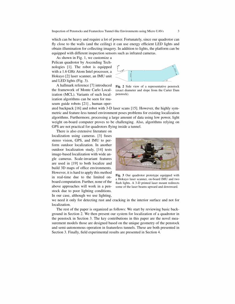
As shown in Fig. 1, we customize aPelican quadrotor by Ascending Tech-nologies [1]. The robot is equippedwith a 1.6 GHz Atom Intel processor, aHokuyo [2] laser scanner, an IMU unitand LED lights (Fig. 3).
A hallmark reference [7] introducedthe framework of Monte Carlo Local-ization (MCL). Variants of such local-ization algorithms can be seen for mu-seum guide robots [21] , human oper-ated backpack [16] and robot with 3-D laser scans [15]. However, the highly sym-metric and feature-less tunnel environment poses problems for existing localizationalgorithms. Furthermore, processing a large amount of data using low power, lightweight on-board computer proves to be challenging. Also, algorithms relying onGPS are not practical for quadrotors flying inside a tunnel.
Fig. 3 Our quadrotor prototype equipped witha Hokuyo laser scanner, on-board IMU and twoflash lights. A 3-D printed laser mount redirectssome of the laser beams upward and downward.
There is also extensive literature onlocalization using cameras. [3] fusesstereo vision, GPS, and IMU to per-form outdoor localization. In anotheroutdoor localization study, [14] testsimage-based localization with wide an-gle cameras. Scale-invariant featuresare used in [19] to both localize andbuild 3D maps of office environments.However, it is hard to apply this methodin real-time due to the limited on-board computation. Further, none of theabove approaches will work in a pen-stock due to poor lighting conditions.In our case, although we use lighting,we need it only for detecting rust and cracking in the interior surface and not forlocalization.
The rest of the paper is organized as follows: We start by reviewing basic back-ground in Section 2. We then present our system for localization of a quadrotor inthe penstock in Section 3. The key contributions in this paper are the novel mea-surement models those are designed based on the unique geometry of the penstockand semi-autonomous operation in featureless tunnels. These are both presented inSection 3. Finally, field experimental results are presented in Section 4.

4 Tolga Ozaslan, Shaojie Shen, Yash Mulgaonkar, Nathan Michael and Vijay Kumar
2 Background
2.1 Quadrotor Dynamics
IMU
LASER
ω1ω1
ω2 ω4
ω3
zquad
zgyro
zacc
xquad
xgyro
xacc
yquad ygyro
yacc
Fig. 4 Coordinate frame definitions of quadro-tor. Due to the manufacturer, gyroscope and ac-celerometer has different orientations which areshown with subscripts of gyro and acc. And bodyframe is denoted by the subscript quad. Dot in acircle means a vector pointing out of the paperplane and an × means the opposite [17].
Quadrotors are basically helicopterswith four propellers located at cornersof a square shape. A schematic of aquadrotor is given in Fig. 4. Each pro-peller is located at equal distances fromthe geometric center of the quadrotor.Motors mounted on opposite sides ro-tate in the same direction, while theothers in the opposite direction. Ideally,while the quadrotor is stationary, mo-ments due to the propellers rotating inopposite directions cancel each other sothat the yaw is kept constant.
As the standard reference triad(SRT) for inertial frame, we use{xW , yW , zW} basis vectors. Then avector in this frame is represented bythe vector
[xW , yW , zW
]T . WhereasSRT of the body frame is defined withthe basis vectors {xB, yB, zB} and avector in this frame is represented as[
xB, yB, zB]T . xB is the heading di-
rection of the quadrotor which can beselected arbitrarily. zB is preferably selected as the upwards direction when thequadrotor is hovering and zW is selected to be pointing in the opposite directionto the gravitation (see Fig. 4 and its caption for illustration). Rotation between thesetwo frames is carried through multiplication with a rotation matrix R ∈ SO(3) anddenoted by BRW . Subscript is the frame from which the vector will be transformedand the pre-superscript is the goal frame.
We use Z−X −Y Euler angles to represent rotation from world to body frame[18]. Yaw, pitch and roll angles are denoted as ψ , θ and φ respectively. Angularvelocity in the body frame is denoted by the vector
[p, q, r
]BWe refer to the work by Mellinger [18] where detailed derivations of dynamic
equations are given. They also linearize about the hover state and present a linearcontroller based on this model.
Inspection of Penstocks and Featureless Tunnel-like Environments using Micro UAVs 5
2.2 Robot Localization
Robot localization, environment mapping and the merging of these two problems,Simultaneous Localization and Mapping (SLAM), has been studied extensively[4, 5, 8, 9, 20, 21]. Filtering based approaches are commonly used for solving thelocalization problem. Two mostly used approaches are based on the Kalman filterand the particle filter.
For systems that satisfy the Gaussian uncertainty model, the Kalman filter andits nonlinear variants (referred to as KF from this point on) yield efficient androbust results. We choose the Unscented Kalman Filter (instead of the standardKalman filter) due to its ability to approximate the propagation of Gaussian randomvectors through nonlinear functions via the propagation of stochastic linearizationpoints [20].
On the other hand, there are many systems with multi-modal, widely spread,and other uncertainty models that are cannot be modeled as Gaussian distributions.For such distributions, the nonparametric particle filter-based approach and variants(referred to as PF from this point on), also known as Monte Carlo methods [7, 21],provide approximate representations of arbitrary probabilistic distributions. Theyare more powerful compared to the the parametric KF-based approaches. However,for systems with relatively large number of degrees of freedom (such as quadrotors),the number of particles that is required to accurately represent the distribution canbe prohibitively large.
The Rao-Blackwellized particle filter decomposes the configuration space in or-der to reduce the dimension of the particle-based distribution approximation. Themain goal is to reduce the required particle count for the particle filter [8, 12] bydesigning a hybrid filter achieved by merging the PF and the KF. That is, for someof the parameters, estimation is done through KF and for others PF is used. In ourapplication, since a robot moves through a featureless tunnel, the localization uncer-tainty for the position along the axis of the tunnel is high and it is hardly a properGaussian distribution. However , the uncertainties in position for the other two di-rections are small and they can be well approximated by Gaussian distributions. Forthe former case, use of PF is meaningful and in the latter case KF is a reasonablechoice.
2.3 Controller Design
We use the linear controller design of [18]. Since our target application requiresmostly stable flight with minimum linear acceleration, linearization of dynamicequations around the hover position can be justified. Our controller utilizes a back-stepping architecture that consists of a position controller and an attitude controller.The high level position controller generates desired orientations based on user spec-ified way-points and the on-board localization feedback. The low level attitude con-troller drives the robot to the desired orientation by adjusting motor RPMs.

6 Tolga Ozaslan, Shaojie Shen, Yash Mulgaonkar, Nathan Michael and Vijay Kumar
As shown in Fig. 6, a trajectory generator is used to generate a trajectory fromthe current pose to the goal pose. At this level we can also incorporate constraintssuch as closest distance to walls, maximum linear and rotational speeds, and otherconstraints.
3 Methodology
3.1 Process and Observation Models
We define the process model with the equation
xt+∆ t = f (xt ,ut ,∆ t) (1)
where x is the state vector and u is the control input derived from IMU. Vectors xand u are defined as:
xT = [x,y,z, x, y, z,ψ,θ ,φ ]W , (2)
uT = [x, y, z, p,q,r]B. (3)
The process model implements dynamics of a quadrotor which have detailed ex-planations in [18]. As it is the case for MEMs sensors, our IMU has both bias andrandom errors. Then the true IMU data becomes
u∗ = u−ubias−urnd (4)
where urnd is a random vector drawn from a normal distribution and ubias is thebias error. The process noise in the xW direction is modeled by an additive randomdisturbance which is distributed normally with known variance.
We are using a Hokuyo laser scanner [2] which can take measurements with a180 degrees span in the xB − yB plane. A 3-D printed dual-mirror mount is fixedon top of the laser scanner to reflect rays in upward (+zB) and downward (−zB)directions [13] (Fig. 3). These measurements together with the orientation estimateand the knowledge of the map are used to localize robot on the yW−zW plane of thetunnel using a derivative of the ICP algorithm. This algorithm uses rays emanatingin the four directions ±zW and ±yW . Note that no rays might be exactly in thesedirections due to the orientation of the robot, in case which we select the closestrays. In following explanations we will call these vectors with uW ,dW ,rW andlW which refer to laser beams closest to the upwards, downwards, rightwards andleftwards directions in the world frame.
We do ray-casting to determine the intersections of the above four sets of vectors(uW ,dW ,rW and lW ) with the map. We call these as uW
c ,dWc ,rWc and lWc . Casting
is done against an occupancy grid map with resolution of 5 cm. After ray-casting,we update robot yW , zW positions such that the discrepancy between the measured

Inspection of Penstocks and Featureless Tunnel-like Environments using Micro UAVs 7
rays and the casted rays reduces. A snapshot of this procedure is illustrated in Fig.7. Also Algorithm 1 explains this method. Due to the convexity of the tunnel cross-section, this algorithm is guaranteed to converge to the correct position.
The on-board attitude estimator supplies roll and pitch data with drift correction;but the yaw needs to be corrected using the laser because the IMU cannot measurethe global yaw angle. However, due to the metal interior of the tunnel, we cannotuse the magnetometer output as a global reference to the yaw angle. For this reason,we estimate the yaw angle with respect to the tunnel using laser scans.We proposea geometric solution to this problem using the fact that intersection of a cylinder(tunnel) and a plane is always an ellipse. It is easy to see that the intersection of aplane with a cylindrical tunnel can result in three different curves which are circle,ellipse and two parallel lines. This curve is a circle only when xW and zB are aligned,which is very unlikely to happen in our case. Other two cases are more likely to beobserved and both can be treated as an ellipse since two parallel lines correspondto the special case of an ellipse with infinite major axis length. So we fit an ellipseto scans and then orientation of the major axis gives negative of the yaw angle upto π radians ambiguity. While we define ψ = 0 to be the case when +xW and +xB
are coincident, the source of ambiguity is due to the lack of any clues to distinguishwhether a scan is taken when robot’s heading is ψ =ψ0 or ψ =ψ0+π . In both casesthe curve due to the laser has the exact same shape. We choose the yaw measurementthat is closest to the current UKF yaw estimate for measurement update.
Fig. 5 A sample laser scan data. Ellipse is fitusing the method in [11]. In order to elimi-nate outliers, we use RANSAC. Outliers aredue to operators moving together with thequadrotor, noise and laser failures.
As seen in Fig. 5, laser data can be noisydue to unmodeled obstacles in the environ-ment, inherent noise in the laser scannerand complete failures. A direct fit to suchdata is very probable to give wrong esti-mates which we experienced several timesduring experiments in development stageand caused crashes. In order to get rid ofthis problem, we use RANSAC [10] whichobviously improves fit quality. Since we donot make fast maneuvers, we make a rea-sonable assumption that quadrotor is almostin hover state, in other words φ ≈ 0 andθ ≈ 0. Otherwise resultant ellipse fit wouldalso reflect the effect of non-zero φ andθ angles and we would need to decouplethese effects to obtain the actual yaw angle.We leave the details of ellipse fitting algo-rithm to [11].
8 Tolga Ozaslan, Shaojie Shen, Yash Mulgaonkar, Nathan Michael and Vijay Kumar
3.2 Rao-Blackwellized Particle Filter Design
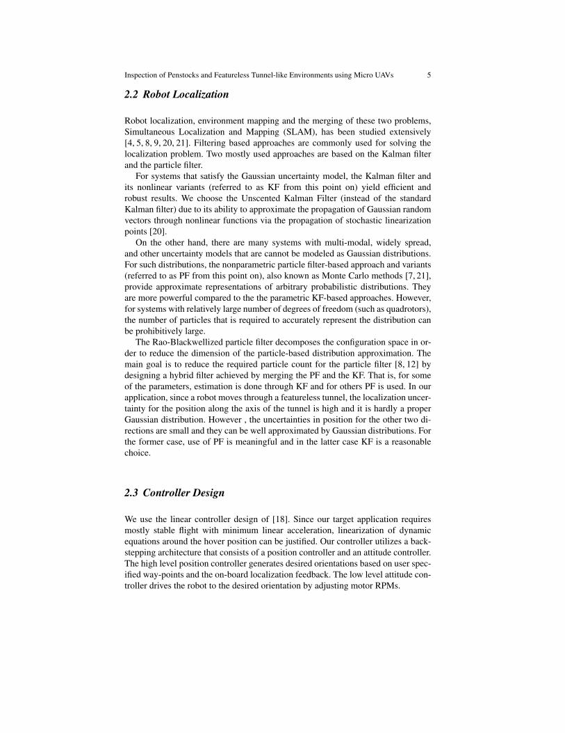
In this model, we carry the well-known UKF prediction using the IMU output. Mea-surement updates for positions and velocities in the yW − zW directions, as well asthe roll, pitch, and yaw orientation are performed within the UKF framework aswell.
Fig. 6 The estimator based on the Rao Blackwell Filter and the PD controller for autonomousflight in a tunnel of known cross section. A particle filter with N particles is used to model thepropagation of state estimates and the uncertainty in the xW direction, while a UKF is used toestimate the remaining states.
A particle filter is used to estimate xW position of robot (Fig. 6) . That is, duringthe prediction step of UKF we make use of gyroscope and accelerometer data andin the measurement update stage we integrate information from the measurementmodels above. The reason using orientation information from the IMU twice whichare the gyroscope data (angular velocity) and the on-board roll-pitch estimation, isbecause of the computational constraints. IMU supplies estimates (roll and pitch) ata rate of 100Hz which we know to be reliable due to the drift correction. But makingmeasurement updates at this rate consumes valuable CPU time. Instead we integratethem at the same rate of laser scanner (30Hz) and carry the low-cost predictionupdate at 100Hz using the gyroscope data (angular velocity). Note that running ameasurement update (UKF update) requires calculation of matrix square root whichis of complexity O(n3). With our current setup, we have chosen not to spend CPUpower with frequent measurement updates.
The overall system design is shown in Fig. 6. We run a particle filter for estimat-ing the position and velocity along xW and an UKF common to all particles to es-timate the remaining state variables which are yW , zW and their derivatives and thethree Euler angles, ψ,θ ,φ . The inputs are data from the laser scanner, the IMU anda grid map. Unless we are close to the junction region of the horizontal and inclined

Inspection of Penstocks and Featureless Tunnel-like Environments using Micro UAVs 9
portions of the tunnel, we don’t have measurements to estimate xW . This impliesthat in such cases uncertainty along this direction can be in any form which may notbe have a closed-form representation. However for all the other states, including lat-eral and vertical positions and orientation, we always have laser measurements. Weexpect a unimodal uncertainty model for these states and use the UKF to estimatethem.
z
y
ey1
ez1
ey2ez2
actual pose
laser scanserror
initial pose
w
w
Fig. 7 Starting from an initial pose, ICP iteratively refines yW − zW positions to reduce discrep-ancy between laser data and robot pose. Red vectors are the error vectors to be minimized. Al-though in the horizontal region of the tunnel cross-section is circular, in inclined region it will bean ellipse as seen by the robot.
When the robot is away from the junction region of the two portions of the pen-stock, laser scanner cannot make any readings since the closest wall is farther thanthe maximum range of the laser scanner. This invalidates the measurement modelexplained for yW − zW estimation. Instead we use Algorithm 2 as the measurementmodel to calculate the weight for each particle. When there are valid measurements,particles consistent with them will be given more importance hence will survivein the importance sampling. Otherwise all particles are given the same weight andimportance sampling favors them equally. As we get consecutive measurement fail-ures, distribution of the particles spread out widely according to the IMU noisemodel. Note the power in representing arbitrary distributions with particles is obvi-ously not achievable with a Gaussian assumption.
In Algorithm 2, to find the weight of a particle, similar to what we do in Algo-rithm 1, we define a set of vectors, fW , which are the closest laser beams to xW
direction. Then we cast these vectors against the grid map to obtain fWc . The weightof a particle is the reciprocal of |(fW−fWc )x|2. In case we don’t have a valid reading,we assign a non-significant weight.
Depending on the availability of valid laser measurements along the axis of thetunnel, we constrain the regions to resample particles in. In case of valid measure-
10 Tolga Ozaslan, Shaojie Shen, Yash Mulgaonkar, Nathan Michael and Vijay Kumar
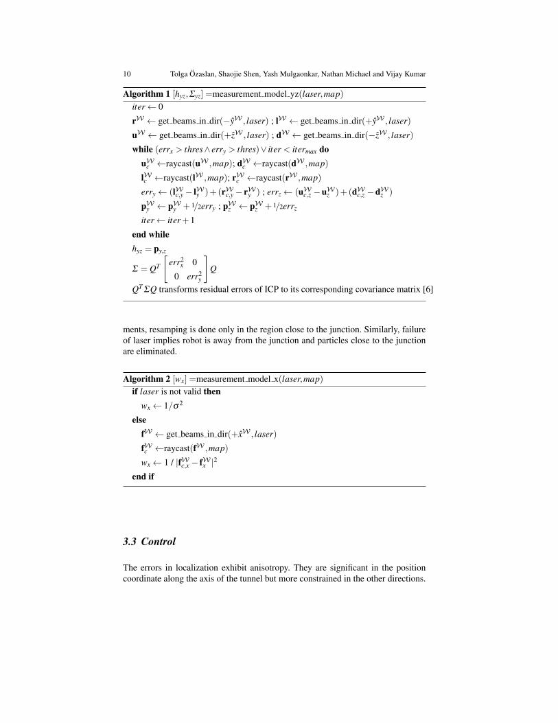
Algorithm 1 [hyz,Σyz] =measurement model yz(laser,map)iter← 0
rW ← get beams in dir(−yW , laser) ; lW ← get beams in dir(+yW , laser)
uW ← get beams in dir(+zW , laser) ; dW ← get beams in dir(−zW , laser)
while (errx > thres∧ erry > thres)∨ iter < itermax douW
c ←raycast(uW ,map); dWc ←raycast(dW ,map)
lWc ←raycast(lW ,map); rWc ←raycast(rW ,map)
erry← (lWc,y− lWy )+(rWc,y− rWy ) ; errz← (uWc,z −uW
z )+(dWc,z −dW
z )
pWy ← pW
y + 1/2erry ; pWz ← pW
z + 1/2errz
iter← iter+1
end whilehyz = py,z
Σ = QT
[err2
x 0
0 err2y
]Q
QT ΣQ transforms residual errors of ICP to its corresponding covariance matrix [6]
ments, resamping is done only in the region close to the junction. Similarly, failureof laser implies robot is away from the junction and particles close to the junctionare eliminated.
Algorithm 2 [wx] =measurement model x(laser,map)if laser is not valid then
wx← 1/σ2
elsefW ← get beams in dir(+xW , laser)
fWc ←raycast(fW ,map)
wx← 1 / |fWc,x− fWx |2
end if
3.3 Control
The errors in localization exhibit anisotropy. They are significant in the positioncoordinate along the axis of the tunnel but more constrained in the other directions.
Inspection of Penstocks and Featureless Tunnel-like Environments using Micro UAVs 11
Accordingly we advocate a semi-autonomous control scheme where the the operatorgoals (or goals from a planner) prescribe the yaw angle, lateral and vertical positionsalong the cross section of the tunnel, while the control along the axis of the tunnelis performed by the operator by directly commanding the acceleration through ajoystick.
4 Experimental Work
In this section we present and interpret results of our experimental work. Data forthe experimental work is collected in three different sites: the Carter Dam and theAllatoona Dam, both in Georgia, and in a long building hallway at the University ofPennsylvania.
In the visit to the Carter Dam, two datasets were collected. In the first flight thequadrotor traversed along the horizontal part of the penstock. And in the seconddataset, it flew close to the junction region towards the inclined region. During thesetests, the quadrotor was controlled manually. The proposed localization algorithmwas run off-line using collected data sets.
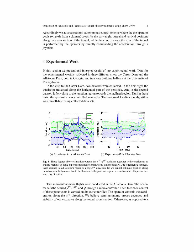
(a) Experiment #1 in Allatoona Dam (b) Experiment #2 in Allatoona Dam
Fig. 8 These figures show estimation outputs for yW -zW positions together with covariances asshaded regions. In these experiments quadrotor flew semi-autonomously. Due to reflective surfaces,laser scanner failed to return readings along xW direction. So we cannot estimate position alongthis direction. Failure was due to the distance to the junction region, wet surface and oblique surfacew.r.t. ray direction.
Two semi-autonomous flights were conducted in the Allatoona Dam. The opera-tor sets the desired yW , zW , and ψ through a radio controller. Then feedback controlof these parameters is carried out by our controller. The operator controls the accel-eration along the xW direction. We believe semi-autonomy proves accuracy andstability of our estimator along the tunnel cross section. Otherwise, as opposed to a

12 Tolga Ozaslan, Shaojie Shen, Yash Mulgaonkar, Nathan Michael and Vijay Kumar
ground robot, faults in controller or estimator would cause unrecoverable instabili-ties.
We conducted a third experiment in a building at the University of Pennsylvania,along a 42 meters long corridor while the quadrotor flew semi-autonomously. In thecorridor experiment, although there are features, such as pillars and doors, the mapwe are using is a featureless rectangular prism. So there is no feature in our map thatwould help in estimating the xW position. Actually those features behave as noisefor yaw estimation which shows robustness of our estimator.
In Fig. 8-9-10 we give results for our Allatoona Dam, Carter Dam and universitybuilding experiments respectively. These experiments show quadrotors can be con-sidered as a reasonable choice for inspection of tunnel-like environments. Only witha laser scanner and an IMU, as a requirement for semi-autonomy, localization alongthe cross-section of the tunnel can be achieved robustly. Also, when one end of thetunnel is in the range of laser scanner, localization along the tunnel axis is achievedas well.
In Fig. 8(b) at 40th seconds, increase in the covariance is due to a worker walkingnear the quadrotor. However, we can handle such cases and estimated position isnot affected. In Fig. 9(a)-10(a), periods when the covariance gets larger is when therobot is away from the end of the tunnel/corridor with the following exceptions.In Fig. 9(a) around 160th seconds increase in uncertainty is due to failure of laserscanner due to water drainage behaving as a mirror. And increase in variance inFig. 10(a) around 100th− 120th and 160th seconds is because quadrotor was tiltedand laser scanner sees the floor. Since the floor is tiled with marble, it behaves as amirror and laser scanner fails.
(a) Experiment #1 in Carter Dam (b) Experiment #1 in Carter Dam
(c) Experiment #2 in Carter Dam (d) Experiment #2 in Carter Dam
Fig. 9 These figures show estimation outputs for xW -yW -zW positions together with covariancesas shaded regions. Opposed to Allatoona Dam tests (see Fig. 8), since the walls of the penstockwas not wet and reflective, we could get readings from the junction region of the tunnel. In Fig.9(a) we can see that during a period of the flight we are able to localize along xW direction. In thesecond experiment we flew the quadrotor close to the junction region and have less time periodswithout valid readings along xW direction. This is shown in Fig. 9(c). High covariance regions inFig. 9(a) correspond to localization failures.

Inspection of Penstocks and Featureless Tunnel-like Environments using Micro UAVs 13
(a) Experiment in university building (b) Experiment in university building
Fig. 10 These figures show results for tests carried in a corridor of length 42 meters in abuilding of University of Pennsylvania. Estimation outputs are given for xW -yW -zW posi-tions together with covariances as shaded regions. Videos of this experiment can be found at:http://mrsl.grasp.upenn.edu/tolga/FSR2013.mp4
5 Conclusion and Future Work
This work presented results of localization and semi-autonomous control of aquadrotor flying in a dam penstock. We used a Rao-Blackwellized particle filter forlocalization consisting of a standard particle filter for localization along the tunnelaxis and a UKF to represent estimates the other five directions. This way we can rep-resent uncertainty along the tunnel axis, which is quite significant compared to theother directions, using an non parametric distribution. Because of this anisotropy,our experiments required the human operator to specify input (acceleration) alongthe tunnel axis while the low-level control software provides for regulation and tra-jectory tracking in the other five directions.
This work is significant because it can replace the tedious and expensive pro-cess of manual inspection involving building scaffolds with human inspectors withsemi-autonomous quadrotors with cameras. We believe that with some training amodestly skilled operator can fly a quadrotor through a tunnel while inspecting im-ages from onboard cameras for defects along the tunnel walls. While our experi-ments were performed in penstocks that are used in dams and hydroelectric powerplants, the same approach can be used for other tunnels such as those encounteredin transportation networks.
Our current work is directed toward addressing more complex (but known) ge-ometries encountered in dams near turbines and to improve the estimation of local-ization errors along the tunnel axis using onboard illumination sources and visualodometry algorithms.
Acknowledgements: We gratefully acknowledge the support of ONR GrantsN00014-07-1-0829 ARL Grant W911NF-08-2-0004, NSF grants 0742304, 1138110,and 1113830, and collaborations with Jennifer Wozencraft and Thomas Hood of theUS Army Corps of Engineers.
14 Tolga Ozaslan, Shaojie Shen, Yash Mulgaonkar, Nathan Michael and Vijay Kumar
References
1. Ascending Technologies GmbH.2. Hokuyo Automatic Co. Ltd.3. M. Agrawal and K. Konolige. Real-time localization in outdoor environments using stereo
vision and inexpensive GPS. In Pattern Recognition, 2006. ICPR 2006. 18th InternationalConference on, volume 3, pages 1063–1068, 2006.
4. W. Burgard, A. Derr, D. Fox, and A.B. Cremers. Integrating global position estimation andposition tracking for mobile robots: the dynamic Markov localization approach. In Intelli-gent Robots and Systems, 1998. Proceedings., 1998 IEEE/RSJ International Conference on,volume 2, pages 730–735 vol.2, 1998.
5. Wolfram Burgard, Armin B. Cremers, Dieter Fox, Dirk Hhnel, Gerhard Lakemeyer, DirkSchulz, Walter Steiner, and Sebastian Thrun. Experiences with an interactive museum tour-guide robot. Artificial Intelligence, 114(12):3 – 55, 1999.
6. Andrea Censi. An accurate closed-form estimate of ICP’s covariance. In Proceedings ofthe IEEE International Conference on Robotics and Automation (ICRA), pages 3167–3172,Rome, Italy, April 2007.
7. F. Dellaert, D. Fox, W. Burgard, and S. Thrun. Monte Carlo localization for mobile robots.In Robotics and Automation, 1999. Proceedings. 1999 IEEE International Conference on,volume 2, pages 1322–1328 vol.2, 1999.
8. Arnaud Doucet, Nando de Freitas, Kevin P. Murphy, and Stuart J. Russell. Rao-Blackwellisedparticle filtering for dynamic bayesian networks. Proceedings of the 16th Conference onUncertainty in Artificial Intelligence, pages 176–183, 2000.
9. H. Durrant-Whyte and Tim Bailey. Simultaneous localization and mapping: part i. RoboticsAutomation Magazine, IEEE, 13(2):99–110, 2006.
10. Martin A Fischler and Robert C Bolles. Random sample consensus: a paradigm for modelfitting with applications to image analysis and automated cartography. Communications of theACM, 24(6):381–395, 1981.
11. A. Fitzgibbon, M. Pilu, and R.B. Fisher. Direct least square fitting of ellipses. Pattern Analysisand Machine Intelligence, IEEE Transactions on, 21(5):476–480, 1999.
12. G. Grisetti, C. Stachniss, and W. Burgard. Improved techniques for grid mapping with Rao-Blackwellized particle filters. Robotics, IEEE Transactions on, 23(1):34–46, 2007.
13. S. Grzonka, G. Grisetti, and W. Burgard. Towards a navigation system for autonomous indoorflying. In Robotics and Automation, 2009. ICRA ’09. IEEE International Conference on, pages2878–2883, 2009.
14. Peter Hansen, Peter Corke, and Wageeh Boles. Wide-angle visual feature matching for outdoorlocalization. Int. J. Rob. Res., 29(2-3):267–297, February 2010.
15. M. Hentschel, O. Wulf, and B. Wagner. A GPS and laser-based localization for urban and non-urban outdoor environments. In Intelligent Robots and Systems, 2008. IROS 2008. IEEE/RSJInternational Conference on, pages 149–154, 2008.
16. T. Liu, M. Carlberg, G. Chen, J. Chen, J. Kua, and A. Zakhor. Indoor localization and visual-ization using a human-operated backpack system. In Indoor Positioning and Indoor Naviga-tion (IPIN), 2010 International Conference on, pages 1 –10, sept. 2010.
17. R. Mahony, V. Kumar, and P. Corke. Multirotor aerial vehicles: Modeling, estimation, andcontrol of quadrotor. Robotics Automation Magazine, IEEE, PP(99):1, 2012.
18. N. Michael, D. Mellinger, Q. Lindsey, and V. Kumar. The GRASP multiple micro-uav testbed.Robotics Automation Magazine, IEEE, 17(3):56 –65, 2010.
19. S. Se, D.G. Lowe, and J.J. Little. Vision-based global localization and mapping for mobilerobots. Robotics, IEEE Transactions on, 21(3):364–375, 2005.
20. Sebastian Thrun, Wolfram Burgard, and Dieter Fox. Probabilistic Robotics. MIT Press, 2005.21. Sebastian Thrun, Dieter Fox, Wolfram Burgard, and Frank Dellaert. Robust Monte Carlo
localization for mobile robots. Artificial Intelligence, 128(12):99 – 141, 2001.