DESIGN OF PENSTOCKS
28
DESIGN OF DESIGN OF PENSTOCKS PENSTOCKS BY BY CGS GUNASEKARA CGS GUNASEKARA NCP DE LIYANAGE NCP DE LIYANAGE
Transcript of DESIGN OF PENSTOCKS

DESIGN OF DESIGN OF PENSTOCKSPENSTOCKS
BY BY
CGS GUNASEKARA CGS GUNASEKARA
NCP DE LIYANAGENCP DE LIYANAGE

IntroductionIntroduction
�� From the forbay tank down to the turbine From the forbay tank down to the turbine water is conveyed through the penstock. water is conveyed through the penstock.
Major componentsMajor components�� ForbayForbay
�� Penstock valuePenstock value
�� Vent pipeVent pipe
�� Support pierSupport pier

Components…..Components…..
�� AnchorsAnchors
�� Drain valveDrain valve
�� Air bleed valueAir bleed value
�� BendsBends
�� Thrust blockThrust block

Major components ( joint types)Major components ( joint types)
�� flangedflanged
�� SocketSocket
�� Sleeve typeSleeve type

Components of penstockComponents of penstock

Material used for Material used for
constructionconstruction……
�� Mild steel Mild steel
�� uPVC (unplastizied polyvinyl uPVC (unplastizied polyvinyl chloride)chloride)
�� HDPE (high density polyethylene)HDPE (high density polyethylene)
�� Ductile iron Ductile iron
�� Prestressed concretePrestressed concrete
�� GRP (glass reinforced plastic)GRP (glass reinforced plastic)

Important factors to be considered Important factors to be considered when selecting materialwhen selecting material ……………..……………..
�� Design PressureDesign Pressure
�� Surface RoughnessSurface Roughness
�� Weight of material Weight of material
�� Ease of transportationEase of transportation
�� Method of jointing Method of jointing
�� Cost of material etcCost of material etc

Constraints in deciding Constraints in deciding diameterdiameter
�� Price Price
�� Head lossHead loss
Compromise:Compromise: Minimum Minimum cost (smallest cost (smallest diameter)diameter)
or or
Minimum Minimum head losshead loss ? (acceptable ? (acceptable head loss)head loss)

Major contributions to head loss, Major contributions to head loss, hhff
* * Friction Friction (due to surface roughness)(due to surface roughness)
hh f f == ½½ . V. V2.2.L.f / g.DL.f / g.D
Darcy’s equationDarcy’s equationV V –– flow velocityflow velocity
L L –– penstock length penstock length
D D ––diameterdiameter
f f ---- friction constantfriction constant
from moody chartfrom moody chart

Major contributions to head Major contributions to head loss, hloss, hff
�� Turbulence Turbulence (( caused by due to caused by due to bends ,inlet, valves ,reductions bends ,inlet, valves ,reductions etc)etc)
hhf f == ∑∑ KKii .V.Vii22 / 2.g / 2.g
KKi i = turbulence loss coefficient= turbulence loss coefficient

Calculation of head loss & diameter Calculation of head loss & diameter
�� CASE STUDYCASE STUDY::-- A steel penstock ,500 m long A steel penstock ,500 m long has a design flow of 0.42 mhas a design flow of 0.42 m33/s and a gross /s and a gross head of 220 m. Calculate and diameter and head of 220 m. Calculate and diameter and wall thickness. head loss < 2% of gross head.wall thickness. head loss < 2% of gross head.
�� Select diameter as , D =300 mm Select diameter as , D =300 mm
�� Flow velocity V = 4.Q / pi .DFlow velocity V = 4.Q / pi .D22
= 5.9 m/s= 5.9 m/s
Renolds no = V.D x 10Renolds no = V.D x 1066
= 1.8x 10= 1.8x 1066

�� Surface roughness of mild steel is, f = 0.3 Surface roughness of mild steel is, f = 0.3
So , K/D = 0.3/300 = 1x 10So , K/D = 0.3/300 = 1x 10--33
from Moody chart f = 0.005,from Moody chart f = 0.005,
From Darcy’s eqFrom Darcy’s eqnn ,,
h h f f == ½ x ½ x 5.95.922 x 500 x 0.0046 / 9.81x 0.25x 500 x 0.0046 / 9.81x 0.25
= 15.0 m= 15.0 m

in our case gross head = 220 min our case gross head = 220 m
H H f f = (15 /220 )x 100 =6.8 %= (15 /220 )x 100 =6.8 %
Calculation of diameter is an Calculation of diameter is an
iterative process , iterative process ,
increase D by 10 mm , increase D by 10 mm ,
now V = 5.5 m/snow V = 5.5 m/s
K/D = 0.3/310 = 9.6 x 10K/D = 0.3/310 = 9.6 x 10--44
Re = V X D = 5.5 X .310 = 1.7 x 10 Re = V X D = 5.5 X .310 = 1.7 x 10 66
corresponding f = 0.005corresponding f = 0.005
hhf f = 12.7 m = 12.7 m
hhff = 5.77 %= 5.77 %

Results of 15 iterationsResults of 15 iterations
iterationsiterations Diameter (mm )Diameter (mm ) hf / (m )hf / (m ) V /(m/s)V /(m/s) %hf%hf
11 300300 1515 5.95.9 6.826.82
22 310310 12.712.7 5.55.5 5.775.77
33 315315 11.811.8 5.35.3 5.365.36
44 320320 10.810.8 5.225.22 4.914.91
55 325325 1010 55 4.554.55
66 330330 9.39.3 4.94.9 4.234.23
77 335335 8.28.2 4.74.7 3.733.73
88 340340 7.77.7 4.64.6 3.503.50
99 350350 6.66.6 4.34.3 3.003.00
1010 355355 6.26.2 4.24.2 2.822.82
1111 360360 5.75.7 4.14.1 2.592.59
1212 365365 5.45.4 44 2.452.45
1313 370370 55 3.93.9 2.272.27
1414 375375 4.74.7 3.83.8 2.142.14
1515 380380 4.34.3 3.73.7 1.951.95

Constraints in deciding wall Constraints in deciding wall thicknessthickness
�� CostCost
�� Strength (withstanding pressure)Strength (withstanding pressure)
Compromize:Compromize: Minimum Minimum costcost
or or
Minimum Minimum strengthstrength ??

Calculation of wall thicknessCalculation of wall thickness
�� Wall should be thick enough to Wall should be thick enough to withstand the maximum water withstand the maximum water pressurepressure
�� Maximum pressure = static + surgeMaximum pressure = static + surge
�� Surge pressure :Surge pressure :-- worst possible case worst possible case
(instantanious closure of (instantanious closure of valve) valve)

Surge pressureSurge pressure , h, hsurgesurge
�� hh surgesurge = C .V / g= C .V / g
�� V V –– flow velocityflow velocity
�� C C –– velocity of pressure wavevelocity of pressure wave
�� C = 1/ [ C = 1/ [ ρρ (1/k+D/E.t) ](1/k+D/E.t) ]½½
�� D D –– diameterdiameter
�� t t –– Wall thicknessWall thickness
�� EE-- Young’s modulus of elasticityYoung’s modulus of elasticity
�� K K –– Bulk modulus of waterBulk modulus of water
�� ρρ –– density of water density of water

�� Thickness ,Thickness ,
ttminmin = = ρρ.g.h.g.hmaxmax.D/ (2..D/ (2.σσTT /S)/S)
�� σσ TT –– ultimate tensile strengthultimate tensile strength
�� S S -- safety factor typically 3 safety factor typically 3
Procedure: Procedure: this is an iterative processthis is an iterative process
11 Estimate tEstimate t
22 Calculate C, hCalculate C, hmaxmax , t, tminmin
33 Compare t withCompare t with ttminmin
44 If t < tIf t < tminmin increase tincrease t
55 if t > tif t > tminmin reduce t close to treduce t close to tminmin
66 Repeat 2 and 3 Repeat 2 and 3

Calculation of penstock wall Calculation of penstock wall ThicknessThickness
Let us select t as 5 mm , D = 380 mmLet us select t as 5 mm , D = 380 mm
�� Iteration 1Iteration 1
�� Iteration 2Iteration 2
�� Iteration 3Iteration 3
�� Iteration 4Iteration 4

Penstock Wall thickness
0
2
4
6
8
10
1 2 3 4 5
Iterations
Th
ick
ne
ss /
mm
Series1

References :References :
�� Micro hydro powerMicro hydro power ––Adam Harvey Adam Harvey ,Andrew Brown , Rod Edward , VAris ,Andrew Brown , Rod Edward , VAris BokaldersBokalders

Thank You !Thank You !

�� okok

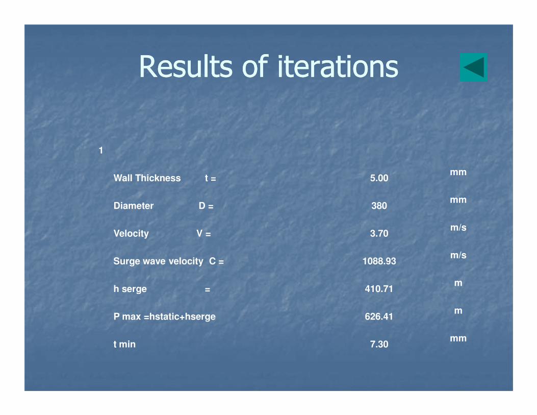
Results of iterationsResults of iterations
1
Wall Thickness t = 5.00 mm
Diameter D = 380mm
Velocity V = 3.70 m/s
Surge wave velocity C = 1088.93 m/s
h serge = 410.71 m
P max =hstatic+hserge 626.41 m
t min 7.30 mm

2
Wall Thickness t = 7.30 mm
Diameter D = 380mm
Velocity V = 3.70 m/s
Surge wave velocity C = 1172.29 m/s
h serge = 442.15 m
P max =hstatic+hserge 657.85 m
t min 7.66 mm

3
Wall Thickness t = 7.66 mm
Diameter D = 380mm
Velocity V = 3.70 m/s
Surge wave velocity C = 1181.93 m/s
h serge = 445.78 m
P max =hstatic+hserge 661.48 m
t min 7.71 mm

4
Wall Thickness t = 7.71 mm
Diameter D = 380mm
Velocity V = 3.70 m/s
Surge wave velocity C = 1183.21 m/s
h serge = 446.27 m
P max =hstatic+hserge 661.97 m
t min 7.71 mm