Ingleside at King Farm - Pennsylvania State University...Company of Baltimore, MD and construction...
82
Prepared by: Stephen A. Tat Prepared for: Professor Kevin M. Parfitt Final Thesis Report The Pennsylvania State University Department of Architectural Engineering Senior Thesis 2008‐2009 Ingleside at King Farm
Transcript of Ingleside at King Farm - Pennsylvania State University...Company of Baltimore, MD and construction...

Prepared by:Stephen A. Tat
Prepared for:Professor Kevin M. Parfitt
Final Thesis Report
The Pennsylvania State UniversityDepartment of Architectural Engineering
Senior Thesis 2008‐2009
Ingleside at King Farm


AE Senior Thesis: Ingleside at King Farm Acknowledgements
Page | 3
Acknowledgements
I would like to acknowledge and thank the following individuals, design professionals, and firms for their help in making this thesis study possible.
Jeffrey Powell CompanyMr. Jeffrey Powell
Turner Construction CompanyMr. Gary Thompson
Turner-KonoverMr. Tom Kobylenski
The Pennsylvania State UniversityDr. Kevin ParfittProfessor Robert Holland
ColleaguesDaniel DoneckerRyan SolnoskyScott RaboldAlisa RaboldMike SpearJoseph Potwatts
Stephen A. Tat Structural 2008 - 2009 | Pennsylvania State University | Final Thesis Report

AE Senior Thesis: Ingleside at King Farm Table of Contents
Page | 4
Table of Contents
Stephen A. Tat Structural 2008 - 2009 | Pennsylvania State University | Final Thesis Report

AE Senior Thesis: Ingleside at King Farm Table of Contents
Page | 5
Table of Contents
Stephen A. Tat Structural 2008 - 2009 | Pennsylvania State University | Final Thesis Report

AE Senior Thesis: Ingleside at King Farm Table of Contents
Page | 6
Table of Contents
Stephen A. Tat Structural 2008 - 2009 | Pennsylvania State University | Final Thesis Report

AE Senior Thesis: Ingleside at King Farm 1. Executive Summary
Page | 7
1. Executive Summary
This final report summarizes the design of a prototype Continuous Care RetirementCommunity (CCRC) for construction on the west coast of the United States using theexisting Ingleside at King Farm King design as a model. The prototype design will berelocated to a high seismic zone in California utilizing steel frame construction, slabon metal deck system, and special concentric braced frames.
The prototype CCRC will have to be redesigned to resist the high seismicity of thewest coast region. Not only will seismic activity affect the outcome of the design, butlocal codes, and the Southwestern U.S. climate will affect it as well. Both the State ofCalifornia and Los Angeles City has their own design requirements. Such as energyconsumption by new buildings, and amendments to ASCE‐07 to design for a moreconservative allowable building drift and seismic expansion joint separations. Theamendments are to account for abnormally large earthquakes due to the citiesproximity to blind thrust faults and soft basin soil resulting in a magnified earthquakedue to direct shear impacts upon the buildings.
The first breadth study includes the research and analysis of implementing anextensive green roof and the usage of Autoclaved Aerated Concrete for precastarchitectural panels to appeal to California’s energy conservation codes. These twodesign decisions are integrated into the second breadth study focusing on theevaluation of the building facade's thermal and moisture resistance performance.The design parameters as a result of the breath studies are integrated into thestructural depth study. Such as how the cladding system and reduced buildingweight affects the energy dissipation of the building during an earthquake, and howthe loads from the roof gardens affects possibilities of soft stories and member sizesin a seismic analysis.
Better performance usually comes with a cost, however there are paybacks that outweights the dollar amount. In the case of retrofitting a building for seismicresistance, the reward could be the reduction in lives lost, medical costs, loss oftenants, loss of assets within the building, and loss of building functions. Otherbenefits include reduction in insurance premiums, increase in property value, andhigher income from tenants.
Redesigning a prototype design of Ingleside at King Farm for Los Angeles, Californiawill be costly due to the special requirements by codes to make the building saferduring and right after a seismic event. Indirect damage includes fires caused byseismic activity, which can weaken the structural system and cause structuralfailures. In the case of extremely high seismic activity, such as the NorthridgeEarthquake in 1994 due to a combination of direct shear and poor soil conditions,retrofitting the building design and to resist seismicity can result in significant savingsdue to decrease in damages and delayed building functions, and more importantly,increasing the safety and survival rate of the occupants.
Stephen A. Tat Structural 2008 - 2009 | Pennsylvania State University | Final Thesis Report

AE Senior Thesis: Ingleside at King Farm 2. Introduction
Page | 8
2. Introduction
2.1 Building Usage
Ingleside at King Farm is owned by the Ingleside Presbyterian Retirement Communityand was designed by Cochran, Stephenson & Donkervoet, Inc. (CSD). The buildingwas constructed under a guaranteed max price of $97 million, which coversconstruction only with a CM contract by general contractor Turner ConstructionCompany of Baltimore, MD and construction manager Turner-Konover of Rockville,MD. Morabito Consultants, Inc. is serving as the engineering firm. Construction ofthe 103 feet, seven- story and 790,000 square footage post-tension concrete buildingbegan on November 1, 2006 and was completed in late March 2009.
The building site is located between a residential and commercial zone. The buildingitself is a mixed-use continuous care retirement center (CCRC) designed with severalroof gardens, independent living units, assisted living units, and nursing units for thetop seven floors. In addition, the first floor consist of many public servicing areasincluding but not limited to a theater, Olympic size swimming pool and a market placeis the first floor. All the floor plans are identical with the exception of the first floorhaving an extended floor area for the swimming pool and market place.
2.2 Rising Demand for CCRC
The Baby Boom generation, born between 1946 and 1964, has just begun to reachretirement age. In 10 to 15 years, Baby Boomer seniors will comprise a large,unprecedented population seeking the amenities and lifestyle that continuing careretirement community (CCRC) living provides. According to Future Age magazineMarch 2009 issue, approximately 78 million baby boomers will reach retirement age,and will want to remain independent and productive, to live in the community andcontinue to contribute. Additionally, in difficult times people seek out family as asource of comfort and support. A CCRC is more than just four walls and a roof, it is acommunity – a large, extended family that looks out after their own.
During bad economic time, people often do nothing and try to wait out the financialcrisis. Many seniors have decided that waiting is detrimental to their long-term well-being. However, one investment they should seriously consider for their health, wealthand quality of life is a fully refundable and guaranteed deposit in a continuing careretirement community (CCRC), which are regulated by State Government and theDepartment of Insurance. CCRCs offer service and housing packages that create anindependent but secure lifestyle not achievable in regular housing, with immediateaccess to assisted living and skilled nursing in the event these services are needed.
The U.S. Census Bureau had estimated that 57.8 million Boomers will still be alive in2030 between the ages 66 to 84, Over 4,000 CCRCs exists in the U.S. today. In amember survey conducted by the American Association of Retired Persons (AARP) in2004, 37% of respondents voiced curiosity about life care systems such as CCRCs.According to MetLife Mature Market Institute, Boomers have $21 Trillion in spendingpower, and according to Money Magazine statistic in 2005, people aged 50 and overmade up 12% of the U.S. population and many have desired and demanded aluxurious lifestyle (Fall 2007 Land Development, National Association of HomeBuilders). However, the supply of CCRCs falls short of the demand side of theBoomers.
Stephen A. Tat Structural 2008 - 2009 | Pennsylvania State University | Final Thesis Report

AE Senior Thesis: Ingleside at King Farm 3. Thesis Statement
Page | 9
3. Thesis Statement
Due to the large Baby Boomer Population, the demand for CCRCs is increasing fasterthan the amount of CCRCs being established. Thus, the Ingleside at King FarmCCRC design will be used as a model for a new prototype design for establishment onthe west coast of the United States.
The prototype design for the west coast will be required to met seismic design criteria.The structural system selection will depend on the availability of type of buildingmaterials and labor/trades associated with the west region. The structural design willabide to required building codes for strength design, and serviceability requirements.
Other considerations include the design of an alternative building envelope to adapt tothe region’s climate, and utilizing emerging design principles such as sustainability.These two topics are usually affected by local codes, and will be addressed in thebreadth studies.
Stephen A. Tat Structural 2008 - 2009 | Pennsylvania State University | Final Thesis Report
AE Senior Thesis: Ingleside at King Farm 4. Building Statistics
Page | 10
4. Building Statistics
4.1 General Building Data
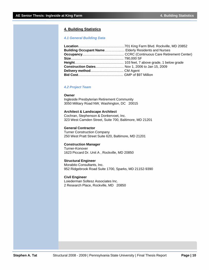
Location.................................................701 King Farm Blvd. Rockville, MD 20852 Building Occupant Name…………..…. Elderly Residents and Nurses Occupancy............................................ CCRC (Continuous Care Retirement Center) Size........................................................ 790,000 SF Height.................................................... 103 feet, 7 above grade, 1 below gradeConstruction Dates.............................. Nov 1, 2006 to Jan 15, 2009 Delivery method................................... CM Agent Bid Cost................................................ GMP of $97 Million
4.2 Project Team
OwnerIngleside Presbyterian Retirement Community3050 Military Road NW, Washington, DC 20015
Architect & Landscape ArchitectCochran, Stephenson & Donkervoet, Inc.323 West Camden Street, Suite 700, Baltimore, MD 21201
General ContractorTurner Construction Company250 West Pratt Street Suite 620, Baltimore, MD 21201
Construction ManagerTurner-Konover1623 Piccard Dr. Unit A , Rockville, MD 20850
Structural EngineerMorabito Consultants, Inc. 952 Ridgebrook Road Suite 1700, Sparks, MD 21152-9390
Civil EngineerLoiederman Soltesz Associates Inc. 2 Research Place, Rockville, MD 20850
Stephen A. Tat Structural 2008 - 2009 | Pennsylvania State University | Final Thesis Report

AE Senior Thesis: Ingleside at King Farm 4. Building Statistics
Page | 11Stephen A. Tat Structural 2008 - 2009 | Pennsylvania State University | Final Thesis Report
4.3 Architecture
Features:• 244 Independent living units • 43 Assisted living units • 16 Skilled nursing units • 10 Dementia units • A theater room • A swimming pool • A tennis court • Underground parking • Roof gardens
Building Aesthetics:
The base of the building consist of cast stones, which gives it a more solid and rusticappearance than the rest of the building. The mid-portion of the building consist ofbrick veneer from the 2nd to 5th floor, and light-beige stucco for the 6th floor. The 7thfloor consist of a mansard roof construction with metal shingles that gives it a welldefined soffit line.
There is rhythm and harmony in the proportioning of the building’s geometry and thefacades. The appearance echoes that of the surround residential buildings. Windowsare all proportional and are evenly spaced apart. Keystones, dormers, lintels andwrought iron shutters are used to give dept to windows and doors.
Building Envelope:
The building envelope consists of three primary wall assemblies. The exterior façadeat the base consist of 16x24 cast stones. It is followed by an air space, ½” sheathing,masonry veneer ties at 16” O.C., 6” steel studs at 16” O.C., 6” batt insulation at an Rvalue of 19 and 5/8” foil face gypsum board.
The mid section of the building (2nd to 5th floor) is similar to the base section exceptthat masonry brick is used in place of the cast stones. On the 6th floor, the exteriorveneer brick is replaced by a light-beige stucco with a reinforcing mesh behind it. The7th floor building envelope consist of a sloped roof assemble (mansard roof style)characterized by dark colored metal shingles on plywood roof sheathing and 4" metalstud framing.
The roof membrane is a 3” rigid insulation on 1 ½” x 20 gauge galvanized metal decksupported by either 26 k12 or 28 k12 joists depending on the roof loads. There arealso a low roof areas (mainly for the roof gardens and penthouse) with an assemblyconsisting of 8” post tension slab with a membrane roof water proofing system.
Sustainable Elements:• High-efficiency pluming • Low E glass • High-efficiency HVAC equip. • Plantings over the plaza • A feature pond • Low VOC coatings

AE Senior Thesis: Ingleside at King Farm 4. Building Statistics
Page | 12Stephen A. Tat Structural 2008 - 2009 | Pennsylvania State University | Final Thesis Report
Major National Model Codes: • 2003 International Building Code • 2003 International Residential Code (with amendments) • 1997 International Plumbing Code • 1996 International Mechanical Code • 1996 National Electrical NFPA-1 • 2003 NFPA 1, 101, 13, 72
Zoning: Planned development zone - The design and construction is in compliance with Chapter 5 of the Rockville City Code.
Major Historical Requirements of Building: None
Due to the building site’s proximately of 0.30 miles from King Farm Farmstead ParkHistoric District, the architectural design is rather conservative and is designed incontext with the existing buildings in the community, but with no historicalrequirements. There is no unique style to describe its architecture. Although itresembles the Victorian style it follows (by choice and not as a requirement) theArchitectural Design Guidelines for the Exterior Rehabilitation of Buildings inRockville’s Historic Districts adopted in 1977.

AE Senior Thesis: Ingleside at King Farm 4. Building Statistics
Page | 13Stephen A. Tat Structural 2008 - 2009 | Pennsylvania State University | Final Thesis Report
4.4 Primary Engineering Systems
Construction:
The developer Penrose Group hired Turner Construction and Konover in a jointventure contract to deliver the Ingleside at King Farm project with a CM Agent deliverymethod. The goal of the project was to deliver affordable living to senior citizens inRockville. Penrose Group had helped finance this project. Construction of the 790,000square foot complex began in November 2006. The complex is a mixed use building:Type I construction. It will consist of living units, office spaces, a multi use theaterspace, Olympic size swimming pool (under a different contract), a market place, andvarious of public spaces for the seniors.
Due to the enormous size of the complex, there are four expansion joints in thebuilding dividing it into five sections. Dividing the building into sections help increasethe constructability and site logistic planning of the project. It helps decrease the lagtime of the construction.
Structural:
The primary structural system present in Ingleside at King Farm is a two-way post-tension flat plate system. Slab thickness for all the floors are 8 inches with 7-wirestrands 1/2 inch diameter tendons. All post-tension floor slabs utilizes normal weightconcrete with f'c of 4,500 psi; except for the structural floor slab holding up the courtyard that is a two-way post-tension flat plate with 10 inch thick drop panels and a 12inch thick slab utilizing normal weight concrete with an f'c of 6,000 psi. The bay sizes(being a two-way system) range from 20 feet to 30 feet. The sub level of the building ismainly used as parking garage and houses most of the building's mechanical rooms.The loads from above are transferred down by 30" x 18" reinforced concrete columnsto spread footings 2 feet below grade on soil with a 5000 psf bearing capacity. Slab ongrade slabs, which are 5 inches thick and has an f'c of 4,000 psi are reinforced with 6"x 6" wielded wire fabric over a vapor barrier and a 4 inch porous fill.
Vertical supporting elements consist of reinforced concrete columns, tubular columnsand W shape. The column grid for the building is irregular with column offsets within10 percent of its span. There are over 140 reinforced concrete columns (typical size18" x 30") each with 10 #8 reinforcing bars rated at 60 ksi located on the sub gradelevel to the 6th floor. The 6" x 6" x 3/8" tube columns are located on the 1st floor atwhere the market place is, which only support the roof loads from above. The steelcolumns on the 7th floor supporting the roof are typically W 8 x 31. Because of thesesteel columns on the 7th floor, which most of them are offset from the alignment of theconcrete columns on the 6th floor, 10 inch thick drop panels are required on the 6thfloor where ever the steel columns on the 7th floor are offset.
There are eleven ordinary reinforced concrete shear walls throughout the building toresist lateral loads. They utilize normal weight concrete with an f'c of 5,000 psi, and arelocated symmetrically about a line of symmetry (North-South) through the center of thebuilding. These shear walls run from the sub level to the 6th floor. The lateralresistance for the 7th floor is provided by moment frames with W 8 x 31 columns andtypically W 12 x 14 girders. These moment frames utilizes a seated frame connectionas specified in Table VIII in the AISC (13th edition).

AE Senior Thesis: Ingleside at King Farm 4. Building Statistics
Page | 14Stephen A. Tat Structural 2008 - 2009 | Pennsylvania State University | Final Thesis Report
The framing system for the exterior walls and partition walls are 6" steel studs at 16"O.C. for floors 1 to 6. The 7th floor, which utilizes a sloped roof assembly, is supportedby light gauge metal framing of varying sizes and W 8 x 31 steel columns. Flat roofareas; typically for green gardens or pent houses uses 8 inch post-tension slabs. Flatroof areas that have no particular usage utilize a metal deck and 26 k 12 or 28 k 12joist system.
Lighting:
The living units utilize a mixture of incandescent lighting and fluorescent lighting.Bathrooms and hallways use down-light incandescent and compact fluorescents.Living and dining rooms consists of incandescent chandeliers. Walk in closets useslong fluorescent acrylics and the balcony areas use wall mounted incandescent. Allnursing units use either long fluorescent or compact fluorescent lighting. The hallwaysconnecting the living units are lit by down-light compact fluorescents.
Interior public areas such as office spaces and office corridors utilize 2' x 2' or 2' x 4'fluorescent lighting. Compact fluorescent lighting is used in the library, multi-purposerooms and corridors connecting these social spaces. Incandescent lighting is used forthe lobby spaces and roof gardens. As for exterior lighting, high intensity discharge(HID) lighting is utilized in the canopy area, walkways, site, landscaping, and parkinggarage. For exterior exits, compact fluorescents are used.
All emergency lighting uses LED with power provided by the emergency powersystem. All lighting for living units and social areas runs on 120 V while the exteriorHID lighting and office lighting runs on 227 V.
Electrical:
Electrical service provided by the local utility company PEPCO enters the buildingfrom two locations; one on the west side of the building and one on the east side. Theservice voltages are transformed down to a 480Y/277V secondary service that is a 3-phase 4 wires system. Each service then feeds to a 4000 Amp main switchboardlocated in an electrical room in the sub grade level. There are 3 electrical rooms onthe northwest end of the sub grade level serving the public spaces and office spaces,two on the second level (one in each wing of the building), and two on the fifthlevel. There are 500 KV transformers in each electrical room on the floors abovegrade converting the voltage down to a 208Y/120 V service. The 208Y/120 service isused for receptacle loads, incandescent lighting, and much of the living units. Themain emergency power system for the building is a 750 KW diesel generator. Poweris distributed from the generator to emergency lighting, fire pumps, elevators, doorcontrols with an automatic transfer switch.
The minimum branch circuit wires for 20 amp circuits are #12 AWG. Circuit length upto 75 feet uses a # 12 AWG wiring for both 120 V and 277 V. For Circuit lengthbetween 75 feet and 150 feet uses a # 10 AWG wiring for 120 V and a # 12 wiring for277 V. For over 150 feet of circuit length, a # 8 and # 10 AWG wiring is used for the120 V and 277 V respectively.

AE Senior Thesis: Ingleside at King Farm 4. Building Statistics
Page | 15Stephen A. Tat Structural 2008 - 2009 | Pennsylvania State University | Final Thesis Report
Mechanical:
A majority of the mechanical and boiler rooms are located in the northwest end of thesub level garage. A positive pressure in the corridors is maintained by 15 Gas-FiredRooftop A/C Units to keep a constant volume air system throughout the living unitsand prevent cross-contamination between them. The rooftop units have at least 15tons of nominal cooling capacity (over 4000 cfm). Economizer units include airdampers, air filters, barometric relief controls and system controls capable ofintroducing up to 100% outdoor air.
A water source heat pump unit (with 175 PSIG and 3500 RPM) is fitted into each livingunits, offices and storage areas. These heat pumps are linked together in a heatpump loop served by 2 Induced Draft Cooling Towers located on the roof top, whichare linked to 2 Plate and Frame Heat Exchangers (for cooling) located in thegarage. The hot water source for these heat pump units are provided by 10 Gas-FiredForced Draft Boilers in boiler room. For additional heat when needed, an electricbaseboard is used. There are 12 Electric Heaters to provide heat for public areas.Memory assist living units are served by a Ductless Split System. The sub levelgarage is heated with small individually controlled electric Unit-Heaters and theexhaust gases are removed with large exhaust fans (5000 cfm) on the north side of thebuilding.
The minimum branch circuit wires for 20 amp circuits are #12 AWG. Circuit length upto 75 feet uses a # 12 AWG wiring for both 120 V and 277 V. For Circuit lengthbetween 75 feet and 150 feet uses a # 10 AWG wiring for 120 V and a # 12 wiring for277 V. For over 150 feet of circuit length, a # 8 and # 10 AWG wiring is used for the120 V and 277 V respectively.
4.5 Additional Engineering Systems
Fire Protection:
Ingleside at King Farm utilizes a wet and dry automatic sprinkler system. The wetsystem is typically used throughout the living units and public areas while the drysystem is used in the garage due to freezing conditions in the winter. The sprinklerhead that is utilized is a chrome pendent type for areas with a suspended ceiling, anda standard upright brass for areas without a suspended ceiling. The main fire alarmcontrol panel is located in the water service room on the garage level, and is linked tofire alarm terminal cabinets on each floor. The terminal cabinets are linked to smokedetectors throughout each floor. A combination of fire and smoke dampers are alsoused in certain areas of the building.
National Fire Protection Association Pamphlet 101 (NFPA 220 – 2003) has determinedthe fire construction type as Type I – 322 constructions. This means that both theexterior walls and structural frame are 3-hour rated, and the floor construction has tobe at least 2-hour rated. Due to the steel frame construction on the 7th floor, asbestosis used as the fire proofing material for the steel frames.

AE Senior Thesis: Ingleside at King Farm 4. Building Statistics
Page | 16Stephen A. Tat Structural 2008 - 2009 | Pennsylvania State University | Final Thesis Report
Transportation:
Transportation throughout the building is handled by six OTIS Gen2 MachineRoomless elevations. They are designed to be cost, energy, installation, and spaceefficient. Five of the six elevators are designated for public usages while theremaining one is for service usage for housing keeping located at the northwestsection of the building. The five public elevators do not require a machine roomadjacent to it. However, they still require a remote space for power distribution andcontrols. There are four main fire exits throughout the building and two mainentrances to the building.
Telecommunications:
All the telecommunications, phone and internet (CAT5E) and cable TV (CATV)services provided by the CATV Company and Verizon enter by the east side of thebuilding through 4” conduits. The lines are run into the telecommunication office roomon the first floor, where the terminal boards are located in. Each living unit is providedwith hard-wire internet connection, telephone and TV.
Security System:
The surveillance system is a closed-circuit television (CCTV) system consisting ofvideo cameras (surface mounted), digital video recorders, monitors, interfacehardware, and cabling. A majority are installed in the sub level garage. A series ofelectric and magnetic locks and card readers are installed throughout the building foroffice usage.
AE Senior Thesis: Ingleside at King Farm 5. Existing Structural System Overview
Page | 17
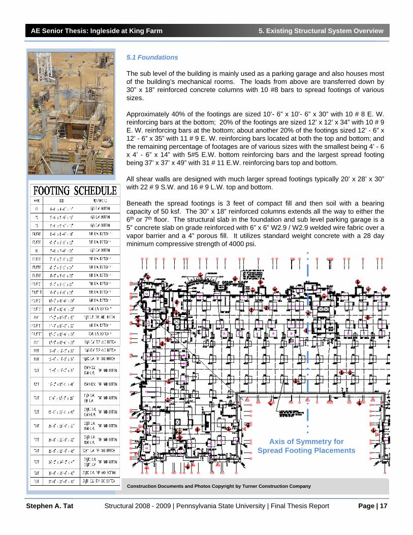
5.1 Foundations
The sub level of the building is mainly used as a parking garage and also houses mostof the building’s mechanical rooms. The loads from above are transferred down by30” x 18” reinforced concrete columns with 10 #8 bars to spread footings of varioussizes.
Approximately 40% of the footings are sized 10’- 6” x 10’- 6” x 30” with 10 # 8 E. W.reinforcing bars at the bottom; 20% of the footings are sized 12’ x 12’ x 34” with 10 # 9E. W. reinforcing bars at the bottom; about another 20% of the footings sized 12’ - 6” x12’ - 6” x 35” with 11 # 9 E. W. reinforcing bars located at both the top and bottom; andthe remaining percentage of footages are of various sizes with the smallest being 4’ - 6x 4’ - 6” x 14” with 5#5 E.W. bottom reinforcing bars and the largest spread footingbeing 37’ x 37’ x 49” with 31 # 11 E.W. reinforcing bars top and bottom.
All shear walls are designed with much larger spread footings typically 20’ x 28’ x 30”with 22 # 9 S.W. and 16 # 9 L.W. top and bottom.
Beneath the spread footings is 3 feet of compact fill and then soil with a bearingcapacity of 50 ksf. The 30” x 18” reinforced columns extends all the way to either the6th or 7th floor. The structural slab in the foundation and sub level parking garage is a5” concrete slab on grade reinforced with 6” x 6” W2.9 / W2.9 welded wire fabric over avapor barrier and a 4” porous fill. It utilizes standard weight concrete with a 28 dayminimum compressive strength of 4000 psi.
Stephen A. Tat Structural 2008 - 2009 | Pennsylvania State University | Final Thesis Report
Axis of Symmetry for Spread Footing Placements
Construction Documents and Photos Copyright by Turner Construction Company

AE Senior Thesis: Ingleside at King Farm 5. Existing Structural System Overview
Page | 18
5.2 Gravity System
The building contains over 140 reinforced columns, which are either 18” x 30” or 12” x30”. Due to the building’s irregular column grid, some columns are miss-counted for inthe column schedule. These reinforced concrete columns extend from the sub level tothe 6th floor.
All 7th floor columns are W 8 x 31 steel rolled. There are approximately 152 of thesesteel columns and 33 of them are offset from the concrete reinforced concretecolumns below. Thus, 5’ x 5’ x 10” drop panels are present on the 6th floor to aid withthe load transfer and punching shear resistance for the offset columns.
The column schedule also does not account for the 6” x 6” x 3/8” steel tubular columnsthat are located in section two of the building where a majority of the public areas arefound. These HSS columns support the gravity loads of areas whose roof line is at thefirst floor and second floor level.
Stephen A. Tat Structural 2008 - 2009 | Pennsylvania State University | Final Thesis Report
Construction Documents and Photos Copyright by Turner Construction Company
Typical Column Sizes
Columns Viewed From Exterior
Columns Viewed From Interior 7th Floor structural drawing showing steel columns offset from reinforced concrete column from the 6th floor and the usage of drop panels for the 7th floor.
Photos showing the transition from reinforced concrete gravity system at the bottom to steel columns on the 7th floor.

AE Senior Thesis: Ingleside at King Farm 5. Existing Structural System Overview
Page | 19
5.3 Two-way Post-tension Flat Plate System
Ingleside at King Farm’s primary structural system is a two-way flat plate post-tensionconcrete structure with 270 ksi unbonded ½ diameter 7 wire tendons. The post-tension concrete slabs are 8 inches thick for typical floors with a compressive strengthof 4500 psi. All Concrete used in this building’s construction is normal weight. Thereare no drop panels or beams supporting these typical slabs. The only drop panels inthe building are found on the sub level columns holding up the 12 inch thick slab(f’c=6000 psi) that is supporting the weight of the court yard, and the 6th floor columnssupporting the 7th floor loads due to the offset W 8 x 31 wide flange columns found onthe 7th floor. All the drop panels are 5’ x 5’ x 10”.
Due to the irregular column gird of the building, bays range from 15 feet to 29.5 feet.For the analysis of alternative floor systems, a bay area of 30’ x 30’ is utilized for amore conservative design, which is the typical interior bay area for the building
Stephen A. Tat Structural 2008 - 2009 | Pennsylvania State University | Final Thesis Report
Banded and Uniformly Spaced Tendons
Construction Documents and Photos Copyright by Turner Construction Company
Typical Tendon Support Bars
Typical Tendon Profile
Typ. Plan Detail-Flair at Tendon Ends
Pipe Sleeves in Concrete Slab

AE Senior Thesis: Ingleside at King Farm 5. Existing Structural System Overview
Page | 20
5.4 Shear Walls
Ingleside at King Farm has eleven shear walls to resist lateral loads from the sub levelup to the 7th floor. Seven of the walls are ordinary reinforced concrete shear wallslocated at stairwells and elevator shafts with #4 horizontal reinforcing bars and #8vertical reinforcing bars. Typical spacing of these bars is 12 inches. All these wallshave a compressive strength of 5000 psi. The remaining four reinforced concreteshear walls have boundary elements and are 15 feet in length; two in east/westdirection and two in north/south direction. Spacing of vertical and horizontalreinforcements is 30 inches and 12 inches respectively. Typical clear cover is 1 ½inches for the reinforcements.
Stephen A. Tat Structural 2008 - 2009 | Pennsylvania State University | Final Thesis Report
Construction Documents and Photos Copyright by Turner Construction Company

AE Senior Thesis: Ingleside at King Farm 5. Existing Structural System Overview
Page | 21
5.5 Moment Frames
On the 7th floor, in addition to the shear walls, there are also (welded/bolted) momentconnections to resist the lateral loads. Based on lateral load analysis in technicalreport one, it was discovered that the loads were largest at the 7th floor roof line. Thus,these moment connections (framed seated beam connection) justify the high windloads that were calculated in technical report one.
Stephen A. Tat Structural 2008 - 2009 | Pennsylvania State University | Final Thesis Report
Construction Documents and Photos Copyright by Turner Construction Company
Photos showing the transition from reinforced concrete gravity system at the bottom to steel columns on the 7th floor.

AE Senior Thesis: Ingleside at King Farm 5. Existing Structural System Overview
Page | 22
5.6 Expansion Joints
There are three true 2-inch expansion joints built into the building. The primary reasonfor these expansion joints is to reduce pre-stress losses in the tendons due to theshortening of the concrete slab caused by shrinkage or cooling, which will inducecracks around restraining boundaries (such as walls and beams).. Another reason isfor better constructability and the utilization time for faster construction. While onesection of the placed slab is left to cure, another section can be worked on. Wherethere exist a 2” true expansion joint in the building, there is a row of double 12” x 30”columns as oppose to the typical 24” x 30” columns on each side of the joint.
Stephen A. Tat Structural 2008 - 2009 | Pennsylvania State University | Final Thesis Report
Building Sections Created by Expansion Joints Exp. Joint Between Sec. 2 & 3
Exp. Joint Between Sec. 3 & 4
Construction Documents and Photos Copyright by Turner Construction Company
Expansion Joints
12” x 30” Columns
Typ. Ceiling Exp. Joint Detail
Typ. Floor Exp. Joint Detail
Roof Exp. Joint Detail
Ext. Wall Exp. Joint Details
Photo Section A
Photo Section A

AE Senior Thesis: Ingleside at King Farm 6. Site Selection
Page | 23
6. Site Selection
The site’s specifications that I propose to have my prototype designed to is Los Angeles, California. The reason being is due to the high seismic activity on the west coast. The Northridge Earthquake occurred on Jan. 17, 1994 in L.A. lasted for about 20 seconds with a moment magnitude of 6.7 and did $20 billion in damage.
Stephen A. Tat Structural 2008 - 2009 | Pennsylvania State University | Final Thesis Report
Reseda Neighborhood (Northridge Earthquake
1994)
LA
Blind thrust faults exist near tectonic plate margins, in the broad disturbance zone. They form when a section of the earth's crust is under high compressive stresses, due to plate margin collision, or the general geometry of how the plates are sliding past each other.
Although usually of magnitude 6 to 7 compared to the largest magnitude 9 earthquakes of recent times, it was especially destructive because the seismic waves are highly directed, and the soft basin soil of the valley can amplify the ground motions tenfold or more

AE Senior Thesis: Ingleside at King Farm 7. Proposed Solutions and Tasks
Page | 24
7. Proposed Solutions and Tasks
7.1 Breadth 1: Green Design
• Implement green building materials into the new prototype (Autoclaved AeratedConcrete)
• Use light weight Autoclaved Aerated Concrete panels (a green building material) to reduce building weight, which in turn reduce the base shear of the building, but still conserve the aesthetics of the original cavity wall design.
• Green Roof Design for Ingleside at King Farm
7.2 Breadth 2: Building Envelope Redesign
• Redesign the building envelope to adjust to the climates in Los Angeles, California.
• Utilize a cladding system for the entire façade to reduce building interfaces of theexisting building design.
• Use light weight Autoclaved Aerated Concrete panels as the material will provide excellent thermal insulation.
• Address structural integrity and code compliances such as cladding issues.
• Analyze thermal and moisture permeability of the building façade.
• Perform cost analysis.
Stephen A. Tat Structural 2008 - 2009 | Pennsylvania State University | Final Thesis Report

AE Senior Thesis: Ingleside at King Farm 7. Proposed Solutions and Tasks
Page | 25
7.3 Structural Depth
• Relocate building site to Los Angeles, California.
• Relocate Seismic Expansion joints to redefine the shape of the building sections/wings to remedy differential vibrations between the sections by creating more symmetrical building sections with uniform mass and stiffness distribution so that the behave in a predictable manner.
• Redefine the center of rigidity and mass of each building sections to reduce torsion by locating seismic‐resisting elements at the extremity of the wings or tie building sections together at lines of stress concentration.
• Redesign structural system from reinforced concrete to steel.
• Re‐align gravity elements (columns) to create a more uniform grid.
• Replace post‐tension slabs with composite steel formed deck.
• Redesign lateral system with special concentric braced frames (SCBF), moment Frames utilizing reduced beam section (RBS) connections based on the Northridge earthquake 1994, and a combination of outriggers and belt truss.
• Establish width of seismic expansion joints to allow for the estimated inelastic deflection of adjacent wings to prevent pounding.
• Utilize the extra height from the 7th floor and Roof Screen, and retrofit the existing steel trusses as a Rooftop Tuned Mass Damper Frame. Isolate the floor containing the mechanical units to create the suspended pendulous mass that will increase the fundamental period, which will result in a decrease in seismic acceleration response of the building section.
Stephen A. Tat Structural 2008 - 2009 | Pennsylvania State University | Final Thesis Report

AE Senior Thesis: Ingleside at King Farm 8. Design Criteria and Goals
Page | 26
8. Design Criteria and Goals
8.1 Codes
8.2 Material Properties
Stephen A. Tat Structural 2008 - 2009 | Pennsylvania State University | Final Thesis Report
Codes, Standards, and GuidesCodes and Standards in Original Design Codes and Standards used for Prototype Design
International Building Code 2003 International Building Code 2006ASCE 7-98: Minimum Design Loads For Buildings and other Structures.
ASCE 7-05: Minimum Design Loads For Buildings and other Structures.
Rockville, MD City Codes: Local amendments. American Institute of Steel Construction (AISC) 13th
EditionAISC Seismic Design Manual
AISC –LRFD 1999, Load and Resistance Factor Design Specification for StructuralSteel BuildingsVulcraft Steel Roof and Deck Catalog
2007 California Building Code Section 1614
ACI 318-08 Building Code Requirements forStructural ConcretePCI Design Handbook - Precast and PrestressedConcreteArchitectural Precast Concrete (2nd ed.)
IBC 2006 Structural/Seismic Design Manual:Building Design Examples for Steel and Concrete.
Material Strength Summary in Existing StructureStructural SteelWide Flange Shapes Fy=50 ksiHollow Structural Steel (HSS) Fy=46 ksiAnchor Rods Fy=55 ksiChannels Fy=36 ksiAngles Fy=36 ksiConcreteStructural Slab Supporting Court Yard F’c = 6000 psi, Normal wt. Slab on Grade/Foundation F’c = 4000 psi, Normal wt.Floor Slab F’c = 4500 psi, Normal wt.Cast-in-place Columns F’c = 5000 psi, Normal wt.Cast-in-place Walls F’c = 5000 psi, Normal wt.Shear Walls F’c = 5000 psi, Normal wt.ReinforcementsDeformed Bars ASTM A615, Fy=60 ksi
Welded Wire Fabric ASTM A18, Fy=70 ksi
Post-Tension Tendons ASTM A-416-74, 270 ksi
Material Strength Summary in Prototype DesignStructural SteelWide Flange Shapes ASTM A572, Grade 50Hollow Structural Steel (HSS) Fy=36 ksiMetal Decking 3.5” composite deck Fy = 40 ksi, 18 gage

AE Senior Thesis: Ingleside at King Farm 8. Design Criteria and Goals
Page | 27
8.3 Design Loads
Stephen A. Tat Structural 2008 - 2009 | Pennsylvania State University | Final Thesis Report
Ground Floor System LoadsSpaces
FaçadeResidential Public
Load Type Material / Usage Reference Load Load Load
Dead Load
Normal Weight Concrete ACI 318 ‐ 08 150 pcf ‐Partition Walls WDG 15 psf ‐
Miscellaneous (M/E/P)ACI 318 ‐ 08
10 psf‐
Cold‐formed, light gauge steel studwalls with insulation and 5/8"
gypsum board
WDG ‐ ‐ 5 psf
6" Precast Concrete Panels (Autoclaved Aerated Concrete ‐
AAC)MSJC ‐ ‐ 34 pcf
Live LoadPublic Corridors/Theater/or Retail
Spaces
ASCE 7 ‐ 05 ‐ 100 psf‐
Living Units ASCE 7 ‐ 05 40 psf ‐
Typical Floor System LoadsSpaces
FaçadeResidential Public
Load Type Material / Usage Reference Load Load Load
Dead Load
Light Weight Concrete ACI 318 ‐ 08110 pcf (30 psf ‐ 3.25" above
flute) ‐Steel Deck ASCE 7 ‐ 05 3 psf ‐
Partition Walls WDG 15 psf ‐Miscellaneous (M/E/P) ASCE 7 ‐ 05 10 psf ‐
Cold‐formed, light gauge steel studwalls with insulation and 5/8"
gypsum board
WDG ‐ ‐ 5 psf
6" Precast Concrete Panels (Autoclaved Aerated Concrete ‐
AAC)MSJC ‐ ‐ 34 pcf
Live LoadCorridors/Theater/or Retail Spaces ASCE 7 ‐ 05 ‐ 100 psf ‐
Living Units ASCE 7 ‐ 05 40 psf ‐ ‐
Roof System LoadsType
Non‐accessible AccessibleLoad Type Material / Usage Reference Load Load
Dead Load
Light Weight Concrete ACI 318 ‐ 08 110 pcf (30 psf ‐ 3.25" above flute)Steel Deck ASCE 7 ‐ 05 3 psf
Cold‐formed, light gauge steel frame AISC 13th ed. by shape (Self weight)Insulation, and waterproofing
membraneAISC 13th ed.
8 psfMetal Shingles 3 psf ‐
Roof Garden (wet) 50 psf
Live LoadOrdinary flat, pitch, and curved roofs ASCE 7 ‐ 05 20 psf ‐
Roof Garden ASCE 7 ‐ 05 ‐ 100

AE Senior Thesis: Ingleside at King Farm 8. Design Criteria and Goals
Page | 28
8.4 Deflection Criteria
8.5 Load Combinations
These load combinations are based on LRFD design method used in generating thecomputer model analysis. A few of the equations are modified combinations perASCE 7‐05 and AISC 341‐05. The Seismic Design Category analyzed was Category D.
Adjusted per Section 12.4.2.31) 1.4(D + F)2) 1.2(D + F + T) + 1.6(L + H) + 0.5(Lr or S or R)3) 1.2D + 1.6(Lr or S or R) + (L or 0.8W)4) 1.2D + 1.6W + L + 0.5(Lr or S or R)5) (1.2 + 0.2SDS)D + ρQE + L + 0.2S6) 0.9D + 1.6W + 1.6H7) (0.9 − 0.2SDS)D + ρQE + 1.6H
where: SDS = 1.08ρ = 1.3 (per ASCE 7‐05 Section 12.3.4.2)QE = effects of horizontal seismic forces from V or Fp.
8.6 Seismic Irregularities
ASCE 7‐05 Section 12.3 code gives the limitations for diaphragm flexibilities and also determines the type of structural irregularity on both the horizontal and the vertical planes of the building.
Irregularities that needs to be check includes:• Horizontal Irregularity• Vertical Irregularity• P‐delta Effects• Inherent Torsion• Accidental Torsion• Overall building Torsion
8.7 Seismic Drifts
Stephen A. Tat Structural 2008 - 2009 | Pennsylvania State University | Final Thesis Report
Deflection Type Minimum CriteriaLive Load Deflection L/360
Total Deflection Limit L/240
Construction Load Deflection L/360
2007 California Building Code
ΔM = Cdδmax (equation 16‐45).
ASCE 7‐05

AE Senior Thesis: Ingleside at King Farm 9. Structural Depth
Page | 29
9. Structural Depth
9.1 Placement or Expansion Joints
The relocation of expansion joints is needed due to the irregular configuration of thebuilding. Two main problems related to seismic performance that may result are:
1. Different vibrations between different wings may result in a local stressconcentration at reentrant corners
2. Torsion may result because of the center of rigidity and center of mass notcoinciding.
The building sections are then designed as independent structures. This report willcover analysis for only section 1 and section 2, because section 2 is similar to section3 due to symmetry. Expansion joints are costly, thus I proposed to reduce theamount to only two. The new location of the expansion joints are based on the ideathat we will consider pounding between the building sections only in the East‐Westdirection during an earthquake. In this case, it will mean less damage to the entirebuilding during an earthquake.
Stephen A. Tat Structural 2008 - 2009 | Pennsylvania State University | Final Thesis Report
148’
281’
136’
90’
66’
135’
N
Building Sections Created by Existing Expansion Joints

AE Senior Thesis: Ingleside at King Farm 9. Structural Depth
Page | 30
9.2 Expansion Joints Specified by Code:
LRFD Specification (AISC) lists expansion and contraction as a serviceability issue andprovides the statement in Section L2, “Adequate provision shall be made forexpansion and contraction appropriate to the service conditions of the structure.”
ASCE 7‐05 Minimum Design Loads for Buildings and Other Structures states,“Dimensional changes in a structure and its elements due to variations intemperature, relative humidity, or other effects shall not impair the serviceability ofthe structure.”
The major temperature difference in LA, California between the record hightemperature and record low temperature is approximately 60° F (From Almanac). Asfor normal temperature change, the average daily change is approximately 20° F.According to a graph in the AISC Steel Construction Manual, the allowable buildinglength for a steel constructed building is approximately 450 feet for a temperaturechange of 60 ° F. The max distance of a building section as a result of my proposedexpansion joint placements is no greater than 281 feet. This meets the design lengthcriteria.
As for minimum building separation (of adjoining structures), L.A , California hadmodified ASCE 7 in Section 1614 in the 2007 California Building Code to allow for themaximum inelastic response displacement :
ΔM = Cdδmax (equation 16‐45).
Where δmax is the calculated maximum displacement at Level x as define in ASCE 7Section 12.8.4.3.
Stephen A. Tat Structural 2008 - 2009 | Pennsylvania State University | Final Thesis Report
450 feet

AE Senior Thesis: Ingleside at King Farm 9. Structural Depth
Page | 31
9.3 Floor System Design
The cost of a filler beam and/or girder beam consists of the cost of the mill material,the cost of fabrication, and the cost of erection. The cost of fabrication and erectionfor a single beam is about the same for a heavy beam . Thus, beams should bespaced as far apart as practical to reduce the number of pieces that has to be madeand erected on site.
Another consideration is the bay sizes. For steel buildings, smaller bay size may notreduce costs. For economy, it is important to reduce the number of pieces to befabricated and erected. Since the cost of fabrication and erection for a small beam isessentially the same as for a large beam, the savings involved in reducing themember weight is primarily savings in the cost of mill material. When the number ofpieces is reduced, the actual cost of fabrication.
Before redesigning the gravity system, the entire column grid for the building isrealigned. Most of the existing concrete columns are offset by approximately 10% ofits span (as permissible by ACI). Spans are then limited to as fewer lengths aspossible to reduce the number of fabrication variations and to make possible to orderthe materials in bulk quantity for cheaper prices.
A RAM model was constructed to aid in the realignment of the column grid andspacing of spans. The maximum and typical span is 30 feet x 30 feet, and will serveas the typical bay size for the design of the floor system. This will also be aconservative design as smaller bay sizes will eventually result with smaller sizedbeams as the 30 feet x 30 feet bays will be supporting public loads that are largerthan the residential loads. Smaller bays will consist typically 25 x 25 feet.
Composite floor systems, consisting of composite metal deck with concrete fill, steelfiller beams, and girders made composite by using headed stud connectors, havebecome a standard type of construction, and are considered by many (engineers andarchitects) to be the highest quality type of construction. The floors are stiffer andmore serviceable than open web joist systems. Fire resistance ratings may beobtained by providing a coat of fireproof material on the structural shape only. Thecombination of the concrete slab (light weight or normal weight) and composite steeldeck require no additional protection when the proper slab thickness is used for arequired fire rating.
Stephen A. Tat Structural 2008 - 2009 | Pennsylvania State University | Final Thesis Report
From AISC Steel Design Guide: Low‐and Medium‐Rise Steel Buildings

AE Senior Thesis: Ingleside at King Farm 9. Structural Depth
Page | 32Stephen A. Tat Structural 2008 - 2009 | Pennsylvania State University | Final Thesis Report
Composite Beam and Formed Metal Deck Slab DesignUse 18 gauge 3 inch formed deck Slab depth = 6.25"
fy=36ksi Light Weight Conc: f'c=3 ksi
Max unshored span = 10.17 ft with 26 to 30 ¾‐in dia. Headed studsRequired Moment for Composite Beam
Mu=1.2 (65.3) + 1.6 (112) = 258 ft kips Use a W 16 x 31 or W 18 x 40
Required Strength for bare steel beam under dead load plus construction live
Mu=1.2(65.3) + 1.6(40) = 142 ft kip
Mp = 203 ft kip > 142 ft kip Use a W16 x 31 is ok for beamServiceability CriteriaLive Load Deflection L/360 Total Deflection Limit L/240 Construction Load Deflection L/360
30’
W 18 x 55
W 18 x 55
W 18 x 55
W 18 x 55
W 16 x 31
W 16 x 31
Section 1 (Bay under Public Loads)
A typical 30’ by 30’ was chosen for design. The loadsthat this bay is subjected to are all from public areas.
A composite deck design was selected with a maxunshored span of 10.7 feet before designing the girdersand beams.
The use of the ultimate strength design procedure with the LRFD Specification oftenresults in some saving of mill material. In this case, the use of LRFD results in asavings of about 20% in the cost of mill material to the fabricator.
Unshored construction will be used to simplify the work of the contractor. The floorbeams and girders must be designed to support the wet load condition loads as non‐composite sections. Serviceability considerations includes vibrations, floordeflection, and crack control.

AE Senior Thesis: Ingleside at King Farm 9. Structural Depth
Page | 33
Floor System Design Summary
Stephen A. Tat Structural 2008 - 2009 | Pennsylvania State University | Final Thesis Report
Members Sized in RAM
• Girders: W 18 x 40• Infill Beams: W 16x26, W 16 x 31• Beams supporting façade: W 8 x 10, W 14 x 22• Typically W 14 x 43 and W 14 x 90
Comparing the members that were sized in RAM, they are the same
30 x 30 feet Bay
30 x 30 feet Bay

AE Senior Thesis: Ingleside at King Farm 9. Structural Depth
Page | 34
9.4 Lateral Design
System Selection
Braced frames are often the most economical method of resisting lateral loads inmulti‐story buildings. However, the use of bracing bents alone can result in upliftforces even in moderately low high‐rise buildings (10‐15 stories). This may not be aproblem if deep foundations which can resist uplift are used or a combinations ofother systems such as hat or belt trusses can be very. In L.A., California, thegoverning load combinations consist of seismic loads. In addition, Ingleside at KingFarm is from 6 to 7 stories. Uplift will not be a controlling factor in the structuraldesign of this project.
A belt truss system was considered as the 6.25 feet roof parapet surrounding thebuilding will hide the truss located on the roof top. However, due to the irregulargeometry of the building, and architectural plans, it is difficult to design the outriggeror have a core system coinciding with the center of mass and rigidity of each buildingsections without compromising the architectural layout.
A Special Concentric Braced Frame (SCBF) is recommended in areas of highseismicity. The difference between SCBF and OCBF is mainly due to the design of theconnections to give more ductility in response to high seismicity. Ductility is of highdemand for a structural steel system for resisting seismic loads. The SCBF isconsidered to be a better system than the Ordinary Concentric Braced Frame (OCBF)due to the better ductility of the system achieved through individual brace memberdesign and gusset plate design. The brace when axially loaded in compression willeventually buckle, and the direction of brace buckling depends upon the brace shapeorientation and the end restraints of the brace connections of beam to columnmembers. The preferred but difficult to achieve behavior of a SCBF is the in‐planebuckling of the braces.
Due to poor performance during past earthquakes of chevron bracing (both V andinverted V braces), only X bracing or chevron braced frame with a zipper column isrecommended for high seismic loads.
Based on past research, zipper frame or X bracing configurations resulted insimultaneous buckling of the braces at all story levels and hence a well distributedenergy dissipation along the height of the frame during an earth quake. Both V andinverted V alone results in the buckling of bracings and excessive flexure of the beamat mid span where the braces intersect the beam. I proposed to utilize acombination of an inverted V and 2 story X brace system for the prototype design.The 2 story X brace system will be utilized where ever possible without architecturalobstructions, such as hallways. Where ever there exists a hallway, the inverted Vshall be used.
Stephen A. Tat Structural 2008 - 2009 | Pennsylvania State University | Final Thesis Report

AE Senior Thesis: Ingleside at King Farm 9. Structural Depth
Page | 35
Brace Frame Locations
The placement of the brace frames will focus on the matter of having the center ofmass and center of rigidity coinciding with each other as much as possible to reducethe effects of torsion due to lateral forces. It is recommended by code to place thebraces at the exterior perimeter of the building so that the redundancy factor ρ canbe equated to 1.0. However, due to the numerous fenestrations of the buildingenvelope, it is not a feasible decision to locate the brace frames at the perimeter.
Redundancy is based on ASCE section 12.3.4. It was concluded that no more thanone frame takes 33% of the shear when is removed. However, there must be aminimum of 2 frames in each direction along the perimeter, which is not possiblewith this design. As a result, the redundancy factor ρ = 1.3.
Stephen A. Tat Structural 2008 - 2009 | Pennsylvania State University | Final Thesis Report
CR: 141.8, 2954
CM: 140.27, 29.18
Center of Rigidity for SCBFStory X Direction Y DirectionRoof 142.67 29.73
7 142.67 29.736 141.8 29.55 141.8 29.54 141.8 29.53 141.8 29.52 141.8 29.5
Center of Mass for SCBFStory X Direction Y DirectionRoof 140.05 23.19
7 140.05 23.196 140.78 29.185 140.78 29.184 140.78 29.183 140.78 29.182 140.78 29.18
2‐Story X Bracing
Inverted V Bracing

AE Senior Thesis: Ingleside at King Farm 9. Structural Depth
Page | 36Stephen A. Tat Structural 2008 - 2009 | Pennsylvania State University | Final Thesis Report
N-S Direction E-W Direction
Brace Frame Design
Sizing of the frame members and braces were done using excel spreadsheet and waschecked with RAM .
Final Designed members:• Columns: W 16x77, W18x119• Beams: W18 x 106• Braces: HSS 9x9x5/8
AISC 341 requires splices be located in the columns to prevent story mechanisms. Allcolumn splices were located at the mid‐height of the clear column at every otherstory starting with the 3rd story. A plate is bolted on each side of the splice to carrythe shear requirement and a CJP was used to carry the flexural capacity of themembers.
Hinges
30 feet 20 feet

AE Senior Thesis: Ingleside at King Farm 9. Structural Depth
Page | 37
Moment Frame Design
Moment Frames
After the earthquake of Northridge 1994, it was discovered that steel moment framebuildings experience brittle fractures of beam‐to‐column connections. It haddemonstrated that brittle fractures was initiated within connections at very lowlevels of plastic demand and also while the structures remained elastic. Fractures atcomplete joint penetration weld between the beam and bottom flange and columnflange can progress along numerous paths. Due to this event, FEMA 350 prequalifiedseveral connection types. One is the welded flange plate (WFP), the other being areduced beam section (RBS).
The RBS connection utilizes less material, and thus is the preferred choice in theprototype design of Ingleside at King Farm. This connection utilizes circular radiuscuts in both top and bottom flanges of the beam to reduce the flange area over alength of the beam. RBS also has no reinforcing other than the weld metal is used tojoint the flanges of the beam to the column. This is so that plastic hinges will form atthese reduced section areas of the beam. The formation of plastic hinges at thebeam‐column interface during seismic event results in large inelastic strain demandsat the connection leading to brittle failure. The reduced section of the beam at thedesired location of the plastic hinge can remedy this issue.
Strong Column‐Weak Beam
The purpose of a strong column‐weak beam concept is to ensure the frame stability.The formation of plastic hinges in a column can cause failure. Large inelasticdisplacements are produced in the columns as the result of the formation of plastichinges. This inelastic displacement can result in the increase of the P‐delta effectleading to failure. This concept can be achieved in accordance with the requirement
ΣM*pc/ΣMc> 1.0
Stephen A. Tat Structural 2008 - 2009 | Pennsylvania State University | Final Thesis Report
Beam Buckling
AISC‐Seismic specifies the use of sections with a maxiumflange width‐to‐thickness ration of
Bf/2tf = 52/(Fy)0.5
To proved for adequate web stability, the height‐to‐thickness ration of the web shall not exceed
hc/tw = 418/(Fy)0.5
Column Design
When the ration of column moments to beam moments isΣM*
pc/ΣMc < 2.0, columns shall comply with slendernessrequirements.

AE Senior Thesis: Ingleside at King Farm 9. Structural Depth
Page | 38
9.5 Seismic Analysis
Structural Irregularities
Section 12.3 of the ASCE 7‐05 code determines and dictates the limitations fordiaphragm flexibilities, structural irregularity for both horizontal and the verticalplanes of the building. Table 12.6‐1 of ASCE 7 gives the permitted analyticalprocedures for each design class along with the limitations due to a structuralirregularity.
Horizontal structural irregularities were determined according to Section 12.3.2.1.
Vertical structural irregularities determined according to Section 12.3.2.2.
Upon Analyzing the structure and the limiting factors that governs the analyticalprocedure as determined by Section 12.6, Two irregularities exists for section 1 ofIngleside at King Farm. One irregularity is the reentrant corners, the other is astiffness‐story (in the E‐W direction only). The diaphragm connections need a 25%increase in their force as permitted by the Equivalent Lateral Force Procedure (ELFP)and since T<3.5Ts, then it is permitted to use the Equivalent Lateral Force Analysis.This procedure is also more simple to use as oppose to modal analysis.
Stephen A. Tat Structural 2008 - 2009 | Pennsylvania State University | Final Thesis Report
Horizontal Structural Irregularities (Table 12.3.1 ASCE)Type Irregularity Varification Status1a Torsional Checked with RAM Model ok
2 Reentrant CornerAll over the building ‐concentration forces at
cornersNG
3 Diaphragm Discontinuity None by inspecting drawings ok4 Out of Plane Offsets None by inspecting drawings ok
5 Non Parallel SystemAll lateral resisting systems are parallel to major axis
ok
Vertical Structural Irregularities (Table 12.3.2 ASCE)Type Irregularity Varification Status
1a Stiffness‐Soft StoryLevel 6 is a soft story due to
varying heightsNG
2 Weight (Mass)calculated weight of each
story and is fineok
3 Vertical Geometric (66/51)=1.29 < 1.3 ok
4In‐Plane Discontinuity of
Vertical Lateral Force ResistingElements
No by drawing speculations ok
5a, 5Discontinuity on Lateral
StrengthLateral system runs
continuouslyok

AE Senior Thesis: Ingleside at King Farm 9. Structural Depth
Page | 39
Seismic Design Parameters
Seismic calculations were performed using excel spreadsheet following theprocedure prescribed in ASCE 7‐05.
Stephen A. Tat Structural 2008 - 2009 | Pennsylvania State University | Final Thesis Report
Criteria Value Code ReferenceOccupancy Category I Table 1.1Importance Factor 1 Table 11.5‐1
Spectral Acceleration for Short Periods (Ss)
1.656 www.usgs.org
Spectral Acceleration for 1 Second Periods (S1)
0.59 www.usgs.org
Site Coefficient, Fa 1 ASCE 7‐05 Table 11.4‐1
Site Coefficient, Fv 1.5 ASCE 7‐05 Table 11.4‐2
Site Class D Assumed
Seismic Design Category D ASCE 7‐05 Section 11.6
R Factor (SCBF) 6 ASCE 7‐05 Table 12.2‐1 # B3
SMS 1.66 ASCE 7‐05 Equation 11.4‐1
SM1 0.89 ASCE 7‐05 Equation 11.4‐2
SDS 1.104 ASCE 7‐05 Equation 11.4‐3
SD1 0.393 ASCE 7‐05 Equation 11.4‐3
Deflection Amplification Cd 5 ASCE 7‐05 Table 12.2‐1 # B3
Over strength Factor Ω0g 2 ASCE 7‐05 Table 12.2‐1 # B3
Criteria Value Code Referencex 0.75 ASCE 7‐05 Table 12.8.2
Ct 0.02 ASCE 7‐05 Table 12.8.2
hu 94
Ta=Cthux 0.6038
Cu 1.4 ASCE 7‐05 Table 12.8.1T=Ta*Cu 0.845286478
TL 8
(T>TL) CS 0.733370513W 7585.80k 2

AE Senior Thesis: Ingleside at King Farm 9. Structural Depth
Page | 40
Vertical Force Distribution for SCBF
Distribution of the seismic based shear is calculated using ASCE‐07 Section 12.8.3. Csfactor was determined by Section 12.8.1.1 and the overall weight of the building wascalculated before calculating the seismic base shear, distribution factor and forcesand shear per story. Calculations were computed for both E‐W and N‐S directionsdue to an adjustment in the directions when the actual period was inputted after thestructure was initially designed.
Stephen A. Tat Structural 2008 - 2009 | Pennsylvania State University | Final Thesis Report
Vertical Force Distribution N-S DirectionFloor Height (Ft.) Weight (Kips) Cvx Fx (kips) Story ShearRoof 12.00 915.40 0.13 76.69 76.69
7 12.00 930.90 0.13 77.99 154.686 10.00 1142.80 0.14 79.78 234.465 10.00 1143.50 0.14 79.83 314.294 10.00 1144.30 0.14 79.89 394.183 10.00 1147.10 0.14 80.08 474.262 14.00 1161.80 0.19 113.55 587.81Total Weight 7585.8 Kips
Seismic Base Shear 587.81 kipsOverturning Moment 6641.69 kip-ft
Vertical Force Distribution E-W Directionfloor Height (Ft.) Weight (Kips) Cvx Fx (kips) Story ShearRoof 12.00 915.40 0.13 90.05 90.05
7 12.00 930.90 0.13 91.57 181.626 10.00 1142.80 0.14 93.68 275.295 10.00 1143.50 0.14 93.74 369.034 10.00 1144.30 0.14 93.80 462.833 10.00 1147.10 0.14 94.03 556.862 14.00 1161.80 0.19 133.33 690.19Total Weight 7585.8 kips
Seismic Base Shear 690.19 kipsOverturning Moment 7798.48 kip-ft

AE Senior Thesis: Ingleside at King Farm 9. Structural Depth
Page | 41Stephen A. Tat Structural 2008 - 2009 | Pennsylvania State University | Final Thesis Report
Drift and Displacement Calculations for SCBF N‐S Direction
Story Height (Ft.)
Story Displacement (in)
δxe (in) δx (in) Δa (in) Final Results
Roof 12 0.684 0.104 0.475 2.880 ok7 12 0.580 0.117 0.534 2.880 ok6 10 0.463 0.101 0.461 2.400 ok5 10 0.362 0.101 0.461 2.400 ok4 10 0.261 0.096 0.438 2.400 ok3 10 0.165 0.084 0.384 2.400 ok2 14 0.081 0.081 0.370 3.360 ok
Soft Story Check for SCBF N‐S Direction
Story Drift Drift Ratio0.7x the Story Drift
Ratio
0.8x the Story Drift
Ratio
Avg. Story DriftRatio of Next 3
Stories
Soft Story Issue
0.104 0.0087 0.0061 0.0069 ‐ No
0.117 0.0097 0.0068 0.0078 ‐ No
0.101 0.0101 0.0071 0.0081 ‐ No
0.101 0.0101 0.0071 0.0081 0.0095 No
0.096 0.0096 0.0067 0.0077 0.0100 No
0.084 0.0084 0.0059 0.0067 0.0099 No
0.081 0.0058 0.0041 0.0046 0.0094 No
Seismic Drift and Soft Story Checks for SCBF N‐S Direction (Building Section 1)
Drift is a serviceability requirement and should be limited as much as possible,especially building with seismic expansion joints to prevent pounding of the sections.Story drift for each floor was calculated using ASCE 7 chapter 12, equation 12.8‐15and 12.12‐1. Story displacement values were obtained from RAM to calculate theoverall deflections. The tables below summarizes the calculations
Calculations were preformed to see if vertical irregularities existed. Since there werenon, Equivalent Lateral Force Procedure was possible

AE Senior Thesis: Ingleside at King Farm 9. Structural Depth
Page | 42Stephen A. Tat Structural 2008 - 2009 | Pennsylvania State University | Final Thesis Report
Seismic Drift and Soft Story Checks for SCBF E‐W Direction (Building Section 1)
Upon checking for soft story in the E‐W direction, there appears to be a soft storyissue.
Drift and Displacement Calculations for SCBF E‐W Direction
Story Height (Ft.)
Story Displacement (in)
δxe (in) δx (in) Δa (in) Final Results
Roof 12 1.055 0.206 0.988 2.880 ok7 12 0.849 0.176 0.844 2.880 ok6 10 0.673 0.198 0.950 2.400 ok5 10 0.475 0.164 0.784 2.400 ok4 10 0.312 0.162 0.775 2.400 ok3 10 0.150 0.150 0.719 2.400 ok2 14 0.000 0.000 0.000 3.360 ok
Soft Story Check for SCBF E‐W Direction
Story Drift Drift Ratio0.7x the Story Drift
Ratio
0.8x the Story Drift
Ratio
Avg. Story DriftRatio of Next 3
Stories
Soft Story Issue
0.206 0.0172 0.0120 0.0137 ‐ No0.176 0.0147 0.0103 0.0117 ‐ No0.198 0.0198 0.0139 0.0158 0.0106 Yes0.164 0.0164 0.0114 0.0131 0.0172 No0.162 0.0162 0.0113 0.0129 0.0169 No0.150 0.0150 0.0105 0.0120 0.0174 No0.000 0.0000 0.0000 0.0000 0.0158 No

AE Senior Thesis: Ingleside at King Farm 9. Structural Depth
Page | 43Stephen A. Tat Structural 2008 - 2009 | Pennsylvania State University | Final Thesis Report
Torsion Effects
Inherent Torsion
Inherent torsion generally happens when the center of mass and the center ofrigidity are not coinciding near each other. ASCE 7‐05 Section 12.8.4.1 was used toanalyze this issue. It was determined that the building had a rigid diaphragm withCOM and COR almost over lapping each other on all floors. The torsional moments inboth X and Y‐axis are small and negligible.
Accidental Torsion
According to ASCE 7‐05 Section 12.8.4.2, where earthquake forces are appliedconcurrently in two orthogonal directions, the required 5 percent displacement ofthe center of mass need not be applied in both of the orthogonal directions at thesame time, but shall be applied in the direction that produces the greater effect.
This is done by adding a torsional moment at each floor equal to the story forcemultiplied by 5% of the floor dimension perpendicular to the direction of force. Thismethod is equivalent to moving the center of mass by 5% of the plan dimension in adirection perpendicular to the force. If the lateral deflection at either end of thebuilding is more than 20% greater than the average deflection, then the building isclassified as torsionally irregular and accidental eccentricity must be amplified usingthe formula:
For a conservative analysis, I assumed the lateral deflection at one end of thebuilding section to be at least 20% due to building section 1’ length being 148 feet inthe X‐direction (E‐W) resulting in a large shift in the center of mass. The torsionalmoment due to forces in the Y‐direction (N‐S) will likely be greater than the X‐direction because of the buildings length.

AE Senior Thesis: Ingleside at King Farm 9. Structural Depth
Page | 44Stephen A. Tat Structural 2008 - 2009 | Pennsylvania State University | Final Thesis Report
Accidental Torsion Continued
After calculations, it resulted in the amplification factor being less than 1.0 for bothdirections. As for accidental torrsional calculations, there is no torsion irregularity.Torsional shears may be subtracted from direct shears if the torsional shear isreduced by the effects of accidental torsion. Like wise, torsional shears that areincreased by the effects must be added to the direct shears.
Amplification Factor, Ax in the N‐S Direction for SCBFStory δA (in) δB (in) δavg (in) δmax (in) Ax Torsion Irreg.Roof 0.684 0.8208 0.7524 0.8208 0.83 No7 0.58 0.696 0.638 0.696 0.83 No6 0.463 0.5556 0.5093 0.5556 0.83 No5 0.362 0.4344 0.3982 0.4344 0.83 No4 0.261 0.3132 0.2871 0.3132 0.83 No3 0.165 0.198 0.1815 0.198 0.83 No2 0.081 0.0972 0.0891 0.0972 0.83 No
Accidental Torsion in the N‐S Direction for SCBFStory Width Bx (Ft) 5% Bx (Ft) Story Force (K) Ax Factor Torsion (Ft‐K)Roof 148 7.4 76.69 0.83 469.07 148 7.4 77.99 0.83 477.06 148 7.4 79.78 0.83 487.95 148 7.4 79.83 0.83 488.24 148 7.4 79.89 0.83 488.63 148 7.4 80.08 0.83 489.72 148 7.4 113.55 0.83 694.4
Amplification Factor, Ax in the E‐W Direction for SCBFStory δA (in) δB (in) δavg (in) δmax (in) Ax Torsion Irreg.Roof 1.055 1.266 1.1605 1.266 0.83 No7 0.849 1.0188 0.9339 1.0188 0.83 No6 0.673 0.8076 0.7403 0.8076 0.83 No5 0.475 0.57 0.5225 0.57 0.83 No4 0.312 0.3744 0.3432 0.3744 0.83 No3 0.15 0.18 0.165 0.18 0.83 No2 0 0 0 0 0.00 No
Accidental Torsion in the E‐W Direction for SCBFStory Width By (Ft) 5% By (Ft) Story Force (K) Ax Factor Torsion (Ft‐K)Roof 50 2.5 90.05 0.83 186.057 50 2.5 91.57 0.83 189.196 66 3.3 93.68 0.83 255.495 66 3.3 93.74 0.83 255.654 66 3.3 93.8 0.83 255.823 66 3.3 94.03 0.83 256.452 66 3.3 133.33 0.00 0.00
AE Senior Thesis: Ingleside at King Farm 9. Structural Depth
Page | 45
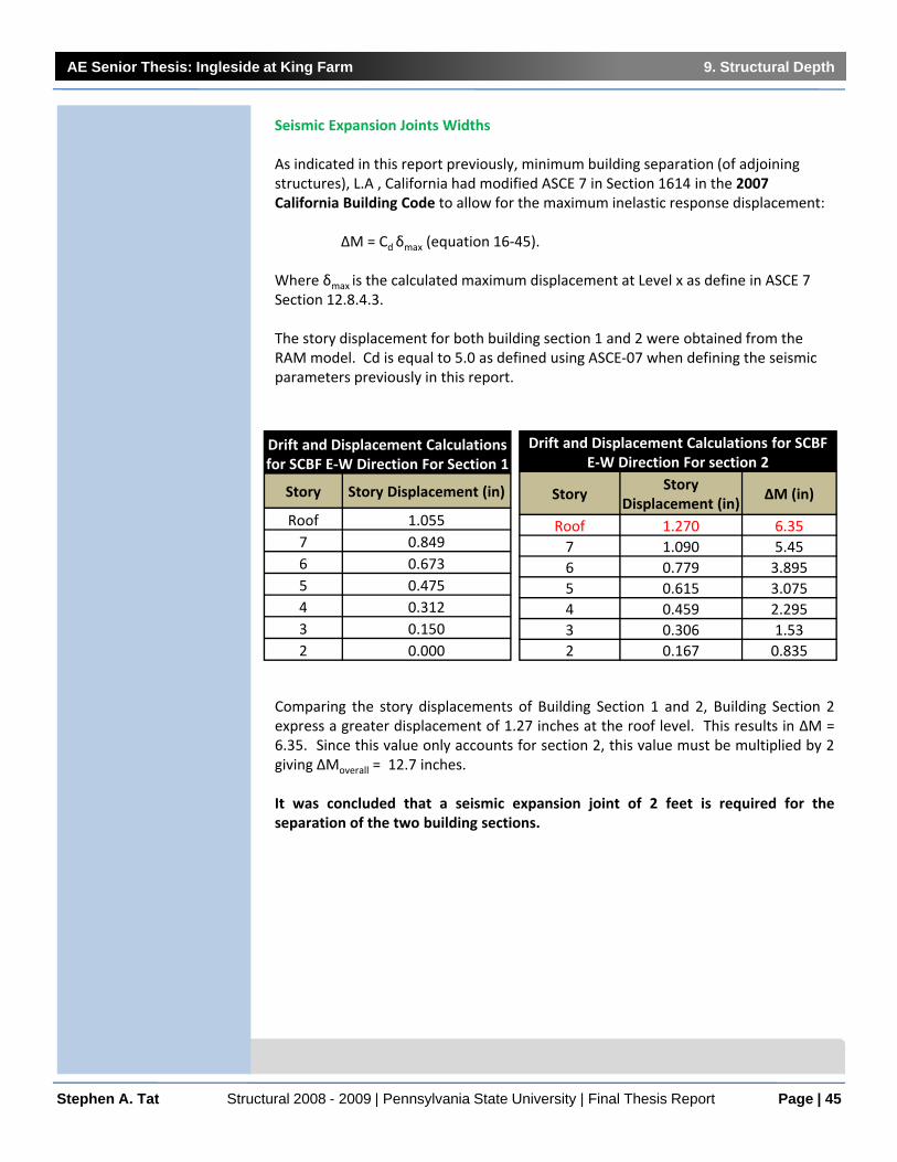
Seismic Expansion Joints Widths
As indicated in this report previously, minimum building separation (of adjoining structures), L.A , California had modified ASCE 7 in Section 1614 in the 2007 California Building Code to allow for the maximum inelastic response displacement:
ΔM = Cdδmax (equation 16‐45).
Where δmax is the calculated maximum displacement at Level x as define in ASCE 7Section 12.8.4.3.
The story displacement for both building section 1 and 2 were obtained from the RAM model. Cd is equal to 5.0 as defined using ASCE‐07 when defining the seismic parameters previously in this report.
Comparing the story displacements of Building Section 1 and 2, Building Section 2express a greater displacement of 1.27 inches at the roof level. This results in ΔM =6.35. Since this value only accounts for section 2, this value must be multiplied by 2giving ΔMoverall = 12.7 inches.
It was concluded that a seismic expansion joint of 2 feet is required for theseparation of the two building sections.
Stephen A. Tat Structural 2008 - 2009 | Pennsylvania State University | Final Thesis Report
Drift and Displacement Calculations for SCBF E‐W Direction For section 2
Story Story
Displacement (in)ΔM (in)
Roof 1.270 6.357 1.090 5.456 0.779 3.8955 0.615 3.0754 0.459 2.2953 0.306 1.532 0.167 0.835
Drift and Displacement Calculations for SCBF E‐W Direction For Section 1
Story Story Displacement (in)
Roof 1.0557 0.8496 0.6735 0.4754 0.3123 0.1502 0.000

AE Senior Thesis: Ingleside at King Farm 10. Green Design Implementations
Page | 46
10. Breadth 1: Green Design
Governor Schwarzenegger's Green Building Initiative (Executive Order S-20-04),resulted in California being a leading example in reducing the amount of electricity,natural gas, water and other resources that state facilities consume on a daily basis.
“That the California Public Utilities Commission (CPUC) is urged to apply its energyefficiency authority to support a campaign to inform building owners and operatorsabout the compelling economic benefits of energy efficiency measures; improvecommercial building efficiency programs to help achieve the 20% goal; and submit abiennial report to the Governor commencing in September 2005, on progresstoward meeting these goals.”
Calculation of increased R values and resulting energy reductions will be preformed.
10.1 Benefits of Green Buildings:
Environmental benefits:
• Enhance and protect ecosystems and biodiversity • Improve air and water quality • Reduce solid waste • Conserve natural resources
Economic benefits:
• Reduce operating costs • Enhance asset value and profits • Improve employee productivity and satisfaction • Optimize life-cycle economic performance
Health and community benefits:
• Improve air, thermal, and acoustic environments • Enhance occupant comfort and health • Minimize strain on local infrastructure • Contribute to overall quality of life
Stephen A. Tat Structural 2008 - 2009 | Pennsylvania State University | Final Thesis Report

AE Senior Thesis: Ingleside at King Farm 10. Green Design Implementations
Page | 47
10.2 Green Roofs
Green roofs are thin layers of living vegetation installed on top of conventional flat orsloping roofs. Green roofs protect conventional roof waterproofing systems and are apowerful tool in combating the adverse impacts of land development and the loss ofopen space.
Green roofs are divided into two categories:
1) Extensive green roofs, which are 6 inches or shallower and are frequentlydesigned to satisfy specific engineering and performance goals (The preferredchoice in this thesis)
2) Intensive green roofs, which may be quite deep and merge into more familiaron-structure plaza landscapes with promenades, lawn, large perennial plants,and trees.
The challenge in designing extensive green roofs is to replicate many of the benefits ofgreen open space, while keeping them light and affordable.
The most common vegetated roof cover in temperate climates is a single un-irrigated3- to 4-inch layer of lightweight growth media vegetated with succulent plants andherbs. In most climates, a properly designed 3-inch deep vegetated roof cover willprovide a durable, low maintenance system that can have many benefits.
Design Factors
There are many interactive factors that must be taken into account for optimalperformance in each setting:
• Climate, especially temperature and rainfall patterns• Strength of the supporting structure• Size, slope, height, and directional orientation of the roof• Type of underlying waterproofing• Drainage elements, such as drains, scuppers, buried conduits, and drain sheets• Accessibility and intended use• Visibility, compatibility with architecture, and owner's aesthetic preferences• Fit with other "green" systems, such as solar panels• Cost of materials and labor
Benefits
• Controlling storm water runoff• Improving water quality• Mitigating urban heat-island effects• Prolonging the service life of roofing materials• Conserving energy• Reducing sound reflection and transmission• Creating wildlife habitat, and• Improving the aesthetic environment in both work and home settings.
Stephen A. Tat Structural 2008 - 2009 | Pennsylvania State University | Final Thesis Report
http://www.wbdg.org/resources/greenroofs.php

AE Senior Thesis: Ingleside at King Farm 10. Green Design Implementations
Page | 48Stephen A. Tat Structural 2008 - 2009 | Pennsylvania State University | Final Thesis Report
Controlling Storm Water Runoff
The runoff of storm water from paved areas and roofs can cause flooding, erosion,pollution, and habitat destruction. The capacity of green roofs to moderate this runoffthrough both retention (water holding) and detention (flow-slowing). Green roofs sharemany engineering features with conventional storm water management basins, andcompared to many at-grade storm water management practices, vegetated roof coversare unobtrusive, low maintenance, and reliable. They can be designed to achievespecified levels of storm water runoff control, including reductions in both total annualrunoff volume (reductions of 50 to 60 percent are common) and peak runoff rates.
Improving Water Quality
By reducing both the volume and the rate of storm water runoff, green roofs benefitcities with combined sewer overflow (CSO) impacts. However, the research alsoshows that the correct choices of growing medium and plant types are essential forsuccess. In cities with combined storm and waste water sewer systems, storm waterdilutes the sanitary waste water, rendering treatment less efficient.
In urban areas, up to 30% of total nitrogen and total phosphorus released intoreceiving streams is derived from dust that accumulates on rooftops. This can result inecological damage and human health hazards.
Due to the lesser amount of rain fall in LA, California compared with RockvilleMaryland, controlling storm water runoff is not crucial in this thesis.
Mitigating Urban Heat-Island Effects
Covering dark conventional roofs with green roofs can significantly reduce thetemperature above the roof, and have been shown to out-perform white or reflectiveroof surfaces in reducing the ambient air temperature. If sufficient urban surfacesutilizes extensive green roofs, this cooling and improvement of air quality can havesignificant positive effects on human health, especially for the young and elderly incongested urban areas.
Prolonging the Service Life of Roofing Materials
• The multiple layers of the green roof can protect the underlying roof materialsfrom the elements:
• Protecting from mechanical damage (walking on roof top, wind-blown dust anddebris, and animals)
• Shielding from ultraviolet radiation by buffering temperature extremes,minimizing damage from the daily expansion and contraction of the roofmaterials.
A roof assembly that is covered with a green roof can be expected to outlast acomparable roof without a green roof by a factor of at least two, and often three.Researchers expect that they will last 50 years and longer before they requiresignificant repair or replacement.
Due to the huge surface area of exposed white roof, an extensive green roof willprovide Ingleside at King Farm a beneficial life cycle cost for the roof envelope.

AE Senior Thesis: Ingleside at King Farm 10. Green Design Implementations
Page | 49
Conserving Energy
Not all benefits will be equally important in every project or climate. For instance, thecapacity of green roofs to reduce heat flow, and therefore energy demand in buildings,is mostly a warm season phenomenon. As a result, this benefit will be realized mostfully in warm climates like in L.A., California where energy expenditures on airconditioning is an important concern. Energy-related benefits will also be lessimportant in multi-story buildings, due to the low ratio of roof area to the total ofexposed building skin. Because green roofs are more complex than simple insulators,project-specific building envelope analysis is required to predict energy conservationunder specific project conditions.
Reducing Sound Reflection and Transmission
Green roofs can absorb a portion of the sound that bounces off hard roofing surfaces.A 3-inch deep vegetative cover can be expected to reduce sound transmission by aminimum of 5 decibels. Sound abatement of up to 46 decibels has been measured onthicker roofs.
Creating Wildlife Habitat
Green roofs can be used to create wildlife habitats to supplement or replacediminishing open space in developing areas.
Improving the Aesthetic Environment
Green roofs offer interesting new opportunities for architectural design. A green roofcan allow a structure to merge with the surrounding landscape, provide a dramaticaccent, or reinforce the defining aspects of the structure's geometry. However, due tothe 6’ - 6” roof parapet, green roof aesthetics is not a major concern with Ingleside atKing Farm.
Stephen A. Tat Structural 2008 - 2009 | Pennsylvania State University | Final Thesis Report

AE Senior Thesis: Ingleside at King Farm 10. Green Design Implementations
Page | 50
Choosing the Right System
Stephen A. Tat Structural 2008 - 2009 | Pennsylvania State University | Final Thesis Report
Comparison of Extension and Intensive Green Roof SystemsEXTENSIVE GREEN ROOF INTENSIVE GREEN ROOF
Thin growing medium; little or no irrigation; stressful conditions for plants;
low plant diversity
Deep soil; irrigation system; more favorable conditions for plants; high
plant diversity; often accessible
Adv
anta
ges
Dis
adva
ntag
es• Lightweight; roof generally does not require reinforcement.
• Suitable for large areas.• Dutiable for roofs with 0 - 30°(slope).
• Low maintenance and long life.• Often no need for irrigation and specialized drainage systems.
• Less technical expertise needed.• Often suitable for retrofit projects.• Can leave vegetation to grow spontaneously.
• Relatively inexpensive.• Looks more natural.• Easier for planning authority to demand as a condition of planning approvals.
• Greater diversity of plants and habitats.
• Good insulation properties.• Can simulate a wildlife garden on the ground.
• Can be made very attractive visually.
• Often accessible, with more diverse utilization of the roof. i.e. for recreation, growing food, as open space.
• More energy efficiency and storm water retention capability.
• Longer membrane life.
• Less storm water retention benefits.
• More limited choice of plants.• Usually no access for recreation or other uses.
• Unattractive to some, especially in winter.
• Greater weight loading on roof.• Need for irrigation and drainage systems requiring energy, water, materials.
• Higher capital & maintenance costs.
• More complex systems and expertise.

AE Senior Thesis: Ingleside at King Farm 10. Green Design Implementations
Page | 51
Green Roof Design Analysis
Stephen A. Tat Structural 2008 - 2009 | Pennsylvania State University | Final Thesis Report

AE Senior Thesis: Ingleside at King Farm 10. Green Design Implementations
Page | 52
Reflectance
Stephen A. Tat Structural 2008 - 2009 | Pennsylvania State University | Final Thesis Report

AE Senior Thesis: Ingleside at King Farm 10. Green Design Implementations
Page | 53
Life Cycle Cost Analysis
Initial Cost
According to a consultant on the project, the green roof on the GAP headquarters in SanBruno, CA, cost approximately $24 per square foot because it was one of the first green roofprojects by an American corporation. It was completed in 1995. The costs of green roofshave declined, and the GAP green roof would probably only cost $11 to $14 per square foot($120 to $150/sq m) today (EAD, Los Angeles, CA).
Maintenance
A green roof does have higher maintenance costs than a conventional roof. Maintenanceactivities that must be performed on a green roof are weeding, replanting, and inspectionsof the waterproof membrane. The green roof can also be divided into distinct compartmentswhich can be moved for inspections or, when the time comes, after 30 to 50 years, for thereplacement of the membrane. Electronic leak detection services are also available.Conducting several annual plant inspections and an annual inspection of the roof membraneentails an annual expense of approximately $1 per square foot.
Irrigation
Climate data for 1971 to 2000 shows an annual average of 15 inches of precipitation at theLos Angeles Civic Center. Using a procedure for estimating landscape water needs developedby the University of California Cooperative Extension, it is estimated that a green roof in LosAngeles will require 0.9 cubic feet of additional water per square foot annually (6.7 gallonsper square foot annually). The approximate annual cost of this water assuming a price of$2.20 per hundred cubic feet of water (EAD, Los Angeles, CA) would be $0.020 per squarefoot ($0.22 per square meter) or about $200 per year for a 10,000 square foot (930 squaremeters) green roof.
Even greater water efficiency can be achieved if captured rainwater or gray water can beused for irrigation. A green roof can capture between 10 and 100 percent of incidentalrainfall. Adopting the midpoint of those values (55 percent), under the average annualprecipitation in Los Angeles of about 15 inches, a 10,000 square foot green roof would yield6,250 cubic feet of runoff annually. If all of that were captured, it would supply 70 percent ofthe estimated annual water needs of the roof (EAD, Los Angeles, CA).
Summary of Costs
The benefits provided by a green roof depends on many factors. The direct benefits that canresult from a green roof, such as the decreased cooling expenses is just one of many. Takinginto consideration the many benefits provided by green roofs undoubtedly would yield amuch higher total value. Such as the energy savings and improved air quality to have apresent value (assuming a 20 year project life) of approximately $0.72 per square foot of coolroof (EAD, Los Angeles, CA).
Stephen A. Tat Structural 2008 - 2009 | Pennsylvania State University | Final Thesis Report

AE Senior Thesis: Ingleside at King Farm 10. Green Design Implementations
Page | 54
Placement of Green Roof on Prototype Design
Existing Roof Membrane: White PVC Single Ply System
Prototype Roof Membrane: Extensive Green Roof Usage
Stephen A. Tat Structural 2008 - 2009 | Pennsylvania State University | Final Thesis Report

AE Senior Thesis: Ingleside at King Farm 10. Green Design Implementations
Page | 55
10.3 Choices of Green Materials
I proposed to use AUTOCLAVED AERATED CONCRETE (AAC). The material consists ofapproximately 80 percent air. Due to its low consumption of readily available rawmaterials, excellent durability, energy efficiency compared to manufacturing CMUsand concrete, relative cost effectiveness, produces no pollution, and ability to berecycled, AAC has a “green” designation. The light weight of AAC in relation to itsstrength reduces the seismic base shear, and its fire‐resistant characteristics providefurther advantage against fires commonly associated with earthquakes. (4” thickpanel gives UL fire rating of 4 hours). Other benefits which are more towardsbuilding envelope relevance of high durability resulting in less maintenance, good lifecycle cost, rapid construction and good workability resulting in reduced labor cost,excellent thermal insulation and sound absorption. It is also a low shrinkagematerial compared to concrete and its reduced weight also lowers shipping costs andcost about the same as timber construction.
The material is available in masonry units and precast panels. The usage of a singlematerial with various appearance can reduce the amount of façade interfaces that isin the existing design of Ingleside at King Farm. This will decrease the chances ofinfiltration and moisture penetration into the structure and conditioned spaces.
Ingredients used to make AAC include Portland cement mixed with lime, silica sand,or recycled fly ash (a byproduct from coal‐burning power plants), water, andaluminum powder or paste and the mixed is poured into a mold. The reactionbetween aluminum and concrete causes microscopic hydrogen bubbles to form,expanding the concrete to about five times its original volume. After evaporation ofthe hydrogen, the now highly closed‐cell, aerated concrete is cut to size and formedby steam‐curing in a pressurized chamber (an autoclave). The result is a non‐organic,non‐toxic, airtight material.
Stephen A. Tat Structural 2008 - 2009 | Pennsylvania State University | Final Thesis Report
Panels are available in thicknesses of between 8inches to 12 inches, 24‐inches in width, and lengthsup to 20 feet.
Blocks come 24”, 32”, and 48” inches long, betweenfour to 16 inches thick, and eight inches high.

AE Senior Thesis: Ingleside at King Farm 11. Building Envelope Redesign
Page | 56
11. Building Envelope Redesign
11.1 Aesthetics
The existing façade is a cavitywall of 4 different assembliesas defined in the existingcondition section of this report.Due to this reason, the multipleinterfaces allows a greaterchance for infiltration andmoisture penetration. As specified by IBC 2006 U.S. climate zone map, a vaporbarrier is climate zone 1, 2, 3 ,4 is not required. However, the building site locationhad been moved from Rockville, MD (a heating climate) to L.A., Ca (a coolingclimate). The cavity wall must be designed to prevent moisture penetration andprovide well thermal insulation.
11.2 Choosing an Assembly
The following cavity wall assembly was designed for the prototype:
• Exterior Autoclaved Aerated Concrete Panels ‐ 6.0 inch thick• Air space and drainage plane ‐ 2.5 inch• Paper stand ‐ 8 mil• Plywood sheathing ½ inch• Rigid insulation ‐ 2 inch• Steel Studs ‐5 ½ inch• And gypsum board ‐ ½ inch
The material is available in masonry units and precast panels. The usage of a singlematerial with various appearance can reduce the amount of façade interfaces that isin the existing design of Ingleside at King Farm. This will decrease the chances ofinfiltration and moisture penetration into the structure and conditioned spaces.
Stephen A. Tat Structural 2008 - 2009 | Pennsylvania State University | Final Thesis Report
DeflectionThe allowable lateral deflectionof AERCON wall panels due tolateral load is L/240. In most cases, an 6" thick wall panel is sufficient to resist the design loads in L.A. as wind is not a factor (85 mph per ASCE‐07)
6”

AE Senior Thesis: Ingleside at King Farm 11. Building Envelope Redesign
Page | 57
11.3 Cladding and Anchors
Seismic codes require that heavy panels accommodate movement either by sliding or ductile connections. In high seismic zones, sliding connections is not a good choice, because of the possibility of incorrect adjustments when bolts are used, jamming or binding due to unwanted materials left after installation and jamming due to geometrical change of the structural frame under horizontal forces.
A ductile connection will be utilized in the prototype design of Ingleside at King Farm. One type of ductile connection is a "Push‐pull“ ‐ with Bearing connection at top, tieback connection at bottom.
There is a problem however, with the connections of corner panels and connections.They must be designed to permit panels to slide past one anther with minimumdamage.
Stephen A. Tat Structural 2008 - 2009 | Pennsylvania State University | Final Thesis Report

AE Senior Thesis: Ingleside at King Farm 11. Building Envelope Redesign
Page | 58
11.4 Envelope Performance Evaluation
R‐Value Analysis
After performing a R‐value analysis using HAM software and Excel spreadsheet usingeach materials’ thermal conductivity, and thickness to obtain R values, both resultswere compared to and revealed similar results. Analyzing the overall R value of thesystem, which R=21.89 it is more than adequate as compared to a typical R value of19 for residential homes.
The dew point appears on the exterior side of the concrete panels, which is adesirable condition. In the event that moister or water does penetrate the concretepanels, a 2.5 inch air gap and drainage plane provides the next line of defense.
Stephen A. Tat Structural 2008 - 2009 | Pennsylvania State University | Final Thesis Report
AAC panel, 6 in. 6.00 cavity , 2.5 in. 2.50

AE Senior Thesis: Ingleside at King Farm 11. Building Envelope Redesign
Page | 59
Condensation Analysis
The wall system was analysis for condensation during the summer and winter as well.As seen with the graph, no condensation occurs within the system in both conditions.
Stephen A. Tat Structural 2008 - 2009 | Pennsylvania State University | Final Thesis Report
AAC panel, 6 in. 6.00 cavity , 2.5 in. 2.50
AAC panel, 6 in. 6.00 cavity , 2.5 in. 2.50

AE Senior Thesis: Ingleside at King Farm 12. Comparison of Existing and New Prototype Design
Page | 60
12. Comparison of Existing and New Prototype Design
12.1 Structural Systems Comparison:
Although the prototype system cost almost twice the amount of the existing system,its building structural weight is reduced by about 50%. The prototype system willrequire 8 inches of extra ceiling height due to the depth of the girders, resulting in anincrease of approximately 5 feet in the overall building height. The decrease inbuilding weight can reduce the base shear of the building during a seismic event,which can help reduce the amount of damage received by the building. Concretematerial is replaced with steel, which results in less material usage and less waste. Aspost‐tension is not a common practice on the west coast, labor cost may be moreexpensive. The new prototype system is the better choice for its location in LosAngeles, California.
12.2 Façade Material Comparison:
AAC is cheaper and provides speedy construction and a reduced labor cost. AACconsumes 50% to 20@ less energy than that needed to produce concrete and CMUs.Its thermal efficiency can significantly reduce the cooling loads for the building tocomply with California energy conservation codes. There is also no constructionwaste as the material is 100% recyclable. Its usage can also reduce the buildingweight compared with the brick veneer, and reduce the number of façade interfacesof the existing design to reduce the chances of moisture penetration and infiltration.AAC’s high URL fire rating can also help prevent seismic fire related damage. Theuse of the AAC panels does result in an increase in the thickness of the exterior wallsup to 3 inches, but it will deliver a better building envelope performance resulting inenergy cost savings, and a worthy investment for a building in a high seismic zone.Another disadvantage would be the cost of anchoring connections
Stephen A. Tat Structural 2008 - 2009 | Pennsylvania State University | Final Thesis Report
Structural Systems ComparisonExisting System: Two‐way Flat
Plate Post TensionPrototype System: Composite Steel
Cost $17.18/sq ft 29.28/sq ftStructural Depth 8" slab 3 1/2 " slab 18" girderStructural Weight 100 psf 54 psfFireproofing 2 hr (spray on) 2 hrEffect of Column Grid Must Re‐align ‐Construction Difficulty Difficult (West Coast) EasyLead Time Short Long
Facade Material ComparisonExisting System: Face Brick
VeneerPrototype System: 6" Autoclaved
Aerated Concrete PanelsMaterial Cost $2.75/sq foot $2.30/sq footR‐Value 0.8/ inch 1.25/ inchThickness 4" 6"Structural Weight 38.7 psf 17 psfFireproofing 1.25 hr 4 hrConstruction Difficulty Medium Easy

AE Senior Thesis: Ingleside at King Farm 12. Comparison of Existing and New Prototype Design
Page | 61
12.3 Green Roof Retrofit Comparison
The usage of an extensive green roof can contribute to the reduction of cooling loadsand thus energy consumption and cost by the building. In a life cycle cost analysis, itcan increase the service life of the roof membrane, and can help increase therevenue of the residential building. Environmental improvements includes improvedwater and air quality, which is an emerging issue in Los Angeles due to traffic and airpollutions. It can also reduce reflection and transmission of heat and glare tosurrounding buildings, and mitigate urban heat‐island effects. It can be used tocontrol storm water runoff and improve the aesthetic environment. Although theinitial cost at first may be expensive, it will pay off in a least two years mainly fromrevenues and the reduction of mechanical loads. With such a vast roof surface area,Ingleside and King Farm can significantly benefit from the implementing a green roofsystem. Its extra dead load bears no burden to the structural system asdemonstrated in the design calculations.
Stephen A. Tat Structural 2008 - 2009 | Pennsylvania State University | Final Thesis Report
Roof Retrofit ComparisonExisting System: PVC Single Ply
SystemPrototype System: Green Roof
RetrofitCost $ 3.75/sq ft 15$/sq ftR‐Value 10.75 23.4Structural Weight 40 psf 50 psfReflectivity 95% ‐Emittance 80% ‐Solar Reflectance index 110 ‐Average Survice Life 9.5 50Maintenance Medium to High Low

AE Senior Thesis: Ingleside at King Farm 13. Conclusion
Page | 62
13. Conclusion
Better performance always comes with a cost, however there are paybacks that outweights the dollar amount. In the case of retrofitting a building for seismicresistance, the reward could be the reduction in lives lost, medical costs, loss oftenants, loss of assets within the building, and loss of building functions. Otherbenefits include reduction in insurance premiums, increase in property value, andhigher income from tenants.
Redesigning a prototype design of Ingleside at King Farm for Los Angeles, Californiawill be costly due to the special requirements by codes to make the building saferduring and right after a seismic event. Indirect damage includes fires caused byseismic activity, which can weaken the structural system and cause structuralfailures. In the case of extremely high seismic activity, such as the NorthridgeEarthquake in 1994 due to a combination of direct shear and poor soil conditions,retrofitting the building design and to resist seismicity can result in significant savingsdue to decrease in damages and delayed building functions, and more importantly,increasing the safety and survival rate of the occupants.
Stephen A. Tat Structural 2008 - 2009 | Pennsylvania State University | Final Thesis Report

AE Senior Thesis: Ingleside at King Farm 14. Bibliography
Page | 63
14. Bibliography
14.1 Codes and Standards
ACI 318‐08 Building Code Requirements for Structural Concrete published in January 2008 by the American Concrete Institute.
AISC Design Guide 19: Fire Resistance of Structural Steel Framing published in December 2005 by the American Institute of Steel Construction, Inc.
AISC Seismic Design Manual Second Printing published in October 2006 by the American Institute of Steel Construction, Inc.
ASCE/SEI 7‐05 Minimum Design Loads for Buildings and Other Structures published in 2006 by the American Society of Civil Engineers.
AISC 13th Edition Steel Construction Manual published in December 2005 by the American Institute of Steel Construction, Inc.
ASTM Standard C 1386,2007, "Standard Specification for Precast Autoclaved Aerated Concrete (AAC) Wall Construction Units," ASTM International, West Conshohocken, PA, 2007, DOI: 10.1520/C1386‐07. www.astm.org.
IBC 2006 International Building Code published in January 2006 by the International Code Council, Inc.
IBC 2006 Structural/Seismic Design Manual: Building Design Examples for Steel and Concrete. Published in 2006 by SEAOC.
IBC 2006 Structural/Seismic Design Manual: Code Application Examples. Published in 2006 by SEAOC.
PCI Design Handbook ‐ Precast and Prestressed Concrete (fifth ed.) published in 1999 by the Precast/Prestressed Concrete Institute.
Architectural Precast Concrete (second ed.) published in 1989 by the Precast/Prestressed Concrete Institute.
Vulcraft Steel Roof and Floor Deck published 2007 by The Nucor Corporation.
2007 California Building Code published by LOS ANGELES REGIONAL UNIFORM CODE PROGRAM (LARUCP).
Stephen A. Tat Structural 2008 - 2009 | Pennsylvania State University | Final Thesis Report
AE Senior Thesis: Ingleside at King Farm 14. Bibliography
Page | 64
14.2 Books and Scholarly Journals
Carter, Charles. "Economy in Steel.” Modern Steel Construction (2000).
Cavanaugh, Laura. "Redefining the Green Roof." Journal of Architectural Engineering, Vol. 14 (2008), pp. 4‐6.
Cochran, Michael. "Seismic Design and Steel Connection Detailing." NASCC Proceedings (2003).
Civjan, Scott. "Retrofit of Pre‐Northridge Moment‐Resisting Connections." Journal of Structural Engineering, Vol. 126 (2000), pp. 445‐452.
Estrada, H.. "Cost Analysis in the Design of Open‐Web Castellated Beams." AEI, Vol. 126 (2006), pp. 1‐10.
Fisher, James. "Expansion Joints: Where and How." Modern Steel Construction(2005).
"Green Roofs ‐ Cooling Los Angeles." EAD City of Los Angeles, (2006).
Horatio, Allison. "Low and Medium Rise Steel Buildings." AISC Steel Design Guide Series (2003).
Parker, James. “Pushing the Envelope.” Modern Steel Construction (2007).
Pulaski, Michael. "Constructability Practices to Manage Sustainable Building Knowledge." Journal of Architectural Engineering. Vol. 12 (2006), pp. 83‐92.
Ricker, David. "Value Engineering for Steel Construction.” Modern Steel Construction(2000).
Saunders, Mark. "Seismic Joints in Steel Frame Building Construction." Modern Steel Construction (2005).
Schnitzler, Stefan. "Sustainability and the Built Environment." Applied Research Paper: Autoclaved Aerated Concrete as a Green Material, (2006).
Schutt, Richard. "Telling the CCRC Story." Future Age. April 2009, pp. 34‐35.
Taranath, Bungale. Wind and Earthquake Resistant Buildings. New York: MarcekDekker, 2005.
Waier, Philip R R.S. Means Building Construction Cost Data 2009. 67th ed. published 2008 by R.S.Means, 2007.
Stephen A. Tat Structural 2008 - 2009 | Pennsylvania State University | Final Thesis Report

AE Senior Thesis: Ingleside at King Farm 15. Appendix
Page | 65
15. Appendix
Stephen A. Tat Structural 2008 - 2009 | Pennsylvania State University | Final Thesis Report

AE Senior Thesis: Ingleside at King Farm 15. Appendix
Page | 66Stephen A. Tat Structural 2008 - 2009 | Pennsylvania State University | Final Thesis Report
15.1 LRFD Composite Beam Design
W16x31, Fy=36ksi

AE Senior Thesis: Ingleside at King Farm 15. Appendix
Page | 67Stephen A. Tat Structural 2008 - 2009 | Pennsylvania State University | Final Thesis Report
LRFD Composite Beam Design Continued

AE Senior Thesis: Ingleside at King Farm 15. Appendix
Page | 68Stephen A. Tat Structural 2008 - 2009 | Pennsylvania State University | Final Thesis Report
15.2 Inverted V‐Brace Design
Parametersρ= 1.3
SDS= 1.104DL= 40 kipsS= 0H= 0LL= 20 kipsQE= 90 Kips
ASTM A 500, Grade B, Fy=46 ksi, Fu (minimum tensile stress) = 58 kisi
Puc=1.2D + 0.5L + 0.2S + ρQE + 0.2SDSDPuc= 183.832kips, compression This Governs
Put=0.9D + 1.6H + 0.2S ‐ ρQE ‐ 0.2SDSDPuc= ‐89.832kips, tension
Unbraced Lengthl=H/sinѲ H=0.5*span of 30 ft
(Brace angle) Ѳ= 20
l=15/sin20= 16.430339 use unbraced length 17 feetK=1K*l=1*17=17
Use HSS 9x9x5/8
фcPn = 607 kips
> 183.8 kips ok
Slenderness Ratio required by AISC‐Seismicl/9=1000/(fy)0.5
= 154.30335
l/9= 22.666667< 154.3 ok
Thickness Ratio required by AISC‐Seismic(b or h)/tw=0.64(Es/Fy)0.5
= 16.069415
9/0.58= 15.517241< 16.06 ok

AE Senior Thesis: Ingleside at King Farm 15. Appendix
Page | 69Stephen A. Tat Structural 2008 - 2009 | Pennsylvania State University | Final Thesis Report
15.2 Inverted V‐Brace Design Continued
GivenFrame Column: W14 x 342 Grade 50 Fu=65 ksi
Frame Beam: W18x60 Grade 50 Fu=65 ksiCenter to Center span of frame= 30 ftFactored Axial Load on column Puc= 820kipsDL= 2.3kip/ftLL= 1.04Kip/ft
Beam Critical Parameters1. Beam depth = 18"< 6" ok FEMA Table 350
2. Span‐depth‐ratio = 360/18= 20 > 7permitted minimum for
SMRF ‐ ok
3. Weight of 60 psf < 200psfless than the minimum permitted ‐
ok4. bf/2tf = 7.56/(2*0.695)= 5.44
Max permitted= 52/(Fy)0.5= 7.35 ok5. Thickness of flange tf=0.695 < 1.75 ok6. Beam material A572 Grade 50 permitted by FEMA 350 ok7. Flange reduction will be within FEMA guidelines
ok
Column Critical Parameters
M*pc = ΣZc(Fyc‐(Puc/Ag))
M*pc = 2*672*(65‐(820/101.6))= 76448.32 kip‐in
= 6370.69 kip‐ft
Mc = 2 x 2373 = 4746 kip‐ft
M*pc/ Mc = 6370/4746= 1.34
> 1.0 ok
Connection Design1.Determine length and location of beam flangesa= (0.5 to 0.75)bf = 0.5*11.5 5.77in.b= (0.65 to 0.85)db = 0.75*33.5 25.13in.
2.Determine depth of flange reductio, c
Assume c=0.2 bfb= 0.2*11.5 = 2.33 in
ZRBS= Zzb‐2ctfp(db‐tfb)
= 514‐2*2.33*0.96(33.6‐0.96)= 367.9in3

AE Senior Thesis: Ingleside at King Farm 15. Appendix
Page | 70Stephen A. Tat Structural 2008 - 2009 | Pennsylvania State University | Final Thesis Report
15.3 Moment Connection Design
Mpr = CprRyZbFy=1.15*1.1*367.98*50 =23274.74kip‐in
=1939.56kip‐ft
Vgravity = (1.2D+0.5L)*L'/2=(1.2*2.3+0.5*1.04)*27.9/2 =45.76kips
Vseismic =2Mpr/L'=2*1939.6/27.9 =139.04kips
Vp=Vgravity+Vseismic
=45.76+139 =184.76kips
Mf = 1939.6+184.8*42/12 =2586.40kip‐ft
Mpc = CprRyZbFy=1.15*1.1*514*50 =32510.50kip‐in
=2709.21kp‐ft
Mf=2586 is less than Mpc=2709 ok
3. Mc = Mpr+Vp(x+dc/2) = Mpr + VpSh=1939+184.8*(27.5/12) =2362.5kip‐ft
4. Calculate shear at column faceVf=2Mf/(L ‐ dc) + Vg
=2*2586/(30‐17.5) =413.76Kips
Bolt capacity фRn =43.5 ф=0.7543.5/58 =58 kips
No. of bolts=413.76/58 7.121Use a 8 1‐in diameter A325 bolt as an
alternative to welding

AE Senior Thesis: Ingleside at King Farm 15. Appendix
Page | 71Stephen A. Tat Structural 2008 - 2009 | Pennsylvania State University | Final Thesis Report
15.4 Column Splice Design

AE Senior Thesis: Ingleside at King Farm 15. Appendix
Page | 72Stephen A. Tat Structural 2008 - 2009 | Pennsylvania State University | Final Thesis Report
15.5 Brace‐Beam‐Column Connection Diagram
15.5 Brace‐to‐BeamMidspan Connection Diagram

AE Senior Thesis: Ingleside at King Farm 15. Appendix
Page | 73Stephen A. Tat Structural 2008 - 2009 | Pennsylvania State University | Final Thesis Report
15.6 Brace‐Beam‐Column Connection Design
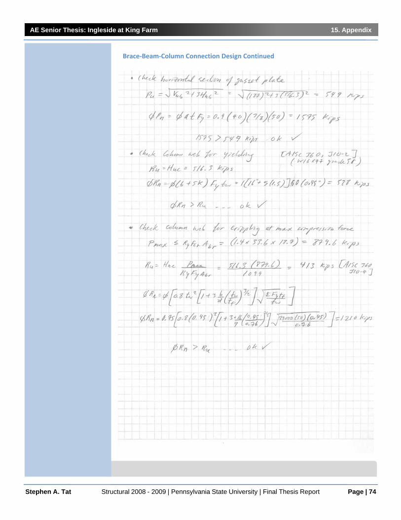
AE Senior Thesis: Ingleside at King Farm 15. Appendix
Page | 74Stephen A. Tat Structural 2008 - 2009 | Pennsylvania State University | Final Thesis Report
Brace‐Beam‐Column Connection Design Continued

AE Senior Thesis: Ingleside at King Farm 15. Appendix
Page | 75Stephen A. Tat Structural 2008 - 2009 | Pennsylvania State University | Final Thesis Report
Brace‐Beam‐Column Connection Design Continued

AE Senior Thesis: Ingleside at King Farm 15. Appendix
Page | 76Stephen A. Tat Structural 2008 - 2009 | Pennsylvania State University | Final Thesis Report
Brace‐to‐BeamMidspan Connection Design

AE Senior Thesis: Ingleside at King Farm 15. Appendix
Page | 77Stephen A. Tat Structural 2008 - 2009 | Pennsylvania State University | Final Thesis Report
RAM Diagram: Section 1 Isometric View

AE Senior Thesis: Ingleside at King Farm 15. Appendix
Page | 78Stephen A. Tat Structural 2008 - 2009 | Pennsylvania State University | Final Thesis Report
RAM Diagram: Section 1 E‐W Section Cut
1

AE Senior Thesis: Ingleside at King Farm 15. Appendix
Page | 79Stephen A. Tat Structural 2008 - 2009 | Pennsylvania State University | Final Thesis Report
RAM Diagram: Section 1 N‐S Section Cut2

AE Senior Thesis: Ingleside at King Farm 15. Appendix
Page | 80Stephen A. Tat Structural 2008 - 2009 | Pennsylvania State University | Final Thesis Report
RAM Diagram: Section 1 7th Floor Plan
RAM Diagram: Section 1 7th Typical 2nd ‐6th Floor Plan

AE Senior Thesis: Ingleside at King Farm 15. Appendix
Page | 81Stephen A. Tat Structural 2008 - 2009 | Pennsylvania State University | Final Thesis Report
RAM Diagram: Section 1 Enlarged Floor Plan View

AE Senior Thesis: Ingleside at King Farm 15. Appendix
Page | 82Stephen A. Tat Structural 2008 - 2009 | Pennsylvania State University | Final Thesis Report
RAM Diagram: Section 2 Plan and Isometric View
Note:
Structural members were not manuallydesigned for section 2 or 3 of Ingleside at KingFarm. Although a RAM Model wasconstructed to obtain drifts anddisplacements easily.