Inflatable Pillow System as a Glass Substitute In Terms of ... · Inflatable Pillow System as a...
203
Inflatable Pillow System as a Glass Substitute In Terms of Building Envelope By Kadri Uygar CANDEMİR A Dissertation Submitted to the Graduate School in Partial Fulfillment of the Requirements for the Degree of MASTER OF ARCHITECTURE Department: Architecture Major: Architecture Izmir Institute of Technology Izmir, Turkey September, 2003
-
Upload
hoangtuong -
Category
Documents
-
view
215 -
download
0
Transcript of Inflatable Pillow System as a Glass Substitute In Terms of ... · Inflatable Pillow System as a...
Inflatable Pillow System as a Glass Substitute
In Terms of Building Envelope
By
Kadri Uygar CANDEMİR
A Dissertation Submitted to the Graduate School in Partial Fulfillment of the
Requirements for the Degree of
MASTER OF ARCHITECTURE
Department: Architecture Major: Architecture
Izmir Institute of Technology Izmir, Turkey
September, 2003
ii
ACKNOWLEDGEMENTS
I will like to express my thanks to Assist. Prof. Dr. Şeniz Çıkış, who has
supervised this thesis, for her great guidance and valuable contributions throughout the
study. I will also like to thank Res. Assist. Karsten Moritz for the valuable information
and the documents he has provided me in the study.
I am grateful to my friends; Gökhan Temiztepe for the technical support, Başak
Güçyeter, Okan Okçu, Özgür Akbulut and Mehmet Özden for their contributions and
help in this study. I owe a very special thanks to Selin Zağpus for her continuous
interest, wonderful guidance, great encouragement and endless patience she has showed
me throughout the study.
Finally I would like to express my gratitude to my family; Emel Canaslan and
Ilgaz Candemir, who have supported me with love, patience and trust throughout my
education and every moment of my life.

iii
ABSTRACT
In the line with the increasing energy demand, there have been many
investigations related with the conservation of energy used in buildings. The systems
and materials used in buildings have an important role in consumption of energy.
Transparent materials and the systems occupies transparent materials contributes this
consumption in positive and negative way due to their design and properties.
Nevertheless, the transparent materials used in buildings as glazing have importance in
order to increase comfort, decrease cost and environmental harm.
This study aims to investigate a contemporary construction system; ETFE foil
pillow system, which is also known as, Inflatable Pillow System made of ETFE Foil. In
the scope of the study, pneumatic pillow system investigated in detail and its
performance evaluated due to environmental control criteria, which can be compared
with other conventional glass glazing products. The study also involves cost analysis
and brief knowledge about contemporary cases that have been completely or partially
constructed with this system. The increase in the amount of transparent surfaces in
contemporary buildings, pointed out that the conventional glazing system are no more
appropriate. Therefore, in specific cases, usage of conventional glass glazing systems
results as a cost increase and loss of comfort. The alternatives of the conventional
glazing systems don’t have appropriate performance or don’t meet the need of the
consumer. Inflatable ETFE foil pillows have better optical properties than glass glazing
systems. Generally, thermal properties of this system equal to the advanced double-
glazing. Light and heat transmission values vary by changing the foil type and number
of layer. Low sound reduction index can be an obstacle or a chance for designers that
should be given attention in design phase. The pillow system that relatively provides
fire and earthquake protection is also lightweight and flexible. Thus, includes many
criteria that are expected in contemporary constructions. The inflatable pillow system
made of ETFE foil can be considered as a safe construction method due to mechanical
properties of the system and the membrane material that is used as pillows. System
reduces operational and maintenance cost for the building. Considerable amount of
expenses for lighting and heating can also be reduced by the usage of the pillow system.

iv
The lightweight nature of the pillow system affects the construction of the whole
building, which also results as a cost reduction.
Pillow system is commonly used for greenhouses and botanical gardens and also
used for sports and leisure halls as well as institutions ands museums. Addition to its
usage as a skylight or façade cover, pillow system can be used as a total envelope that
covers the whole construction underneath.
As a result, this study investigates ETFE foil pillows and their environmental
control properties against conventional glass glazing systems. The results are evaluated
in the line with the information gained. The advantages and disadvantages of the system
as a glazing are given in detail. Although it’s not expected that ETFE pillow system
totally be replaced with the conventional glass glazing system, it constitutes an
alternative glazing system in specific cases.
Keywords: pillow system, pneumatic membrane, glazing, ETFE foil, glass,
fluoropolymer, environmental control criteria

v
ÖZ
Günümüzde, artan enerji ihtiyacına paralel olarak, binalarda kullanılan enerjinin
korunumu konusunda çeşitli araştırmalar yapılmaktadır. Yapının pencere ve benzeri
açıklıkları, kullanılan enerji miktarında önemli bir rol oynamaktadır. Şeffaf
malzemelerle oluşturulan bu yüzeyler, tasarımlarına ve özelliklerine bağlı olarak
harcanan enerji miktarına olumlu veya olumsuz yönde katkı yapmaktadır. Dolayısı ile
yapılarda camlama olarak kullanılan şeffaf malzemelerin ve bunların oluşturdukları
sistemlerin incelenmesi, yapının konfor şartlarının iyileştirilmesi, maliyetin düşürülmesi
ve çevreye verilen zararın azaltılması bakımından oldukça önemlidir.
Bu çalışma, bir fluoropolymer membran olan ETFE folyo ile yapılan camlama
sistemlerinin incelenmesini konu alır. Şişirilebilen yastık sistemi olarak adlandırılan
sistemin, performansının çevresel kontrol kriterleri açısından incelenmesi ve maliyet
analizinin yapılması amaçlanmıştır. Bu pnömatik sistemle yapılan yada sistemi içeren
çağdaş örneklerin irdelenmesi çalışma kapsamındadır. Çağdaş tasarımlarda şeffaf
yüzeylerin artmasıyla, konvansyonel camlama sistemleri konfor açısından yeterli
olamamaya ve yapıya maliyet açısında daha fazla yük getirmeye başlamıştır. Alternatif
camlama malzemeleri de bu ihtiyacı tam anlamıyla karşılayamamışlardır. Genel olarak,
ETFE folyo ile yapılan hava destekli yastık sistemler optik özellikleri dolayısı ile
camdan yüksek ışık geçirim değerine sahiptirler. Sistemin termal özelliğinin ise
yaklaşık olarak çift cama eşdeğer olduğu söylenilebilir. Katman sayısı ve folyo
özellikleri değiştirilerek ışık ve ısı geçirim değerleri değiştirilebilmektedir. Akustik ses
redüksiyon katsayısı oldukça düşük olmasına rağmen tasarımda kullanıma bağlı olarak
yarar sağlayabilmektedir. Göreceli olarak yangın ve deprem güvenliği sağlayan sistem,
hafif ve esnek olması ile de çağdaş mimaride istenen bir çok kriteri bünyesinde
bulundurmaktadır. Bunun yanı sıra, sistemin ve membran malzemenin mekanik
özellikleri ve güvenlik performansı araştırılmıştır. Isı ve ışık giderlerinde önemli
oranlarda indirim sağladığı gibi işletim ve bakım giderlerini de oldukça düşürmüştür.
Ayrıca kullanım şekli ve ölçeğe bağlı olarak yapının taşıyıcı sistemine, dolayısı ile
maliyete katkıda bulunmaktadır.

vi
Yastık sistem, genellikle sera ve botanik bahçeleri ile spor ve eğlence amaçlı
yapılar başta olmak üzere eğitim amaçlı yapılarda, müze ve çeşitli kurumlarda da
kullanım olanağı bulmuştur. Çatıda ve cephede kullanımının yanı sıra yapıyı tamamen
örten bir kabuk gibi kullanıldığı uygulamalar bulunmaktadır.
Sonuç olarak bu çalışmada, binalarda kullanılan konvansyonel camlama
sistemleri ile ETFE folyo ile yapılan şişirilebilen yastık sistemleri çevresel kontrol
kriterleri açısından karşılaştırılarak, elde edilen bilgiler ışığında kullanım alanı ve
olanakları değerlendirilmiştir. Sistemin camlama olarak kullanımın sağladığı yüksek
maliyet avantajı detaylı olarak belirtilmiştir. Tüm bu özellikleri ile hava destekli çok
katmanlı membran sistem, tamamen yerini alması beklenmese de konvansyonel
camlama sistemlerine alternatif oluşturmakta oldukları söylenebilir.
Anahtar kelimeler: yastık sistem, pnömatik membran, camlama, ETFE folyo, cam,
fluoropolymer, çevresel kontrol kriterleri
vii
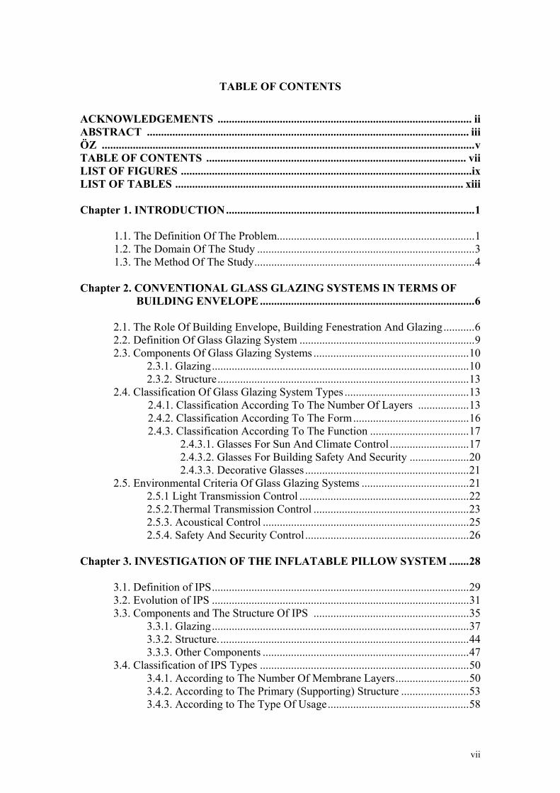
TABLE OF CONTENTS
ACKNOWLEDGEMENTS .......................................................................................... ii ABSTRACT .................................................................................................................. iii ÖZ .................................................................................................................................... v TABLE OF CONTENTS ............................................................................................ vii LIST OF FIGURES .......................................................................................................ix LIST OF TABLES ...................................................................................................... xiii Chapter 1. INTRODUCTION ........................................................................................ 1
1.1. The Definition Of The Problem...................................................................... 1 1.2. The Domain Of The Study ............................................................................. 3 1.3. The Method Of The Study .............................................................................. 4
Chapter 2. CONVENTIONAL GLASS GLAZING SYSTEMS IN TERMS OF
BUILDING ENVELOPE ............................................................................ 6
2.1. The Role Of Building Envelope, Building Fenestration And Glazing ........... 6 2.2. Definition Of Glass Glazing System .............................................................. 9 2.3. Components Of Glass Glazing Systems ....................................................... 10
2.3.1. Glazing ........................................................................................... 10 2.3.2. Structure ......................................................................................... 13
2.4. Classification Of Glass Glazing System Types ............................................ 13 2.4.1. Classification According To The Number Of Layers .................. 13 2.4.2. Classification According To The Form ......................................... 16 2.4.3. Classification According To The Function ................................... 17
2.4.3.1. Glasses For Sun And Climate Control ............................ 17 2.4.3.2. Glasses For Building Safety And Security ..................... 20 2.4.3.3. Decorative Glasses .......................................................... 21
2.5. Environmental Criteria Of Glass Glazing Systems ...................................... 21 2.5.1 Light Transmission Control ............................................................ 22
2.5.2.Thermal Transmission Control ....................................................... 23 2.5.3. Acoustical Control ......................................................................... 25 2.5.4. Safety And Security Control .......................................................... 26
Chapter 3. INVESTIGATION OF THE INFLATABLE PILLOW SYSTEM ....... 28
3.1. Definition of IPS ........................................................................................... 29 3.2. Evolution of IPS ........................................................................................... 31 3.3. Components and The Structure Of IPS ....................................................... 35
3.3.1. Glazing ........................................................................................... 37 3.3.2. Structure. ........................................................................................ 44
3.3.3. Other Components ......................................................................... 47 3.4. Classification of IPS Types .......................................................................... 50
3.4.1. According to The Number Of Membrane Layers .......................... 50 3.4.2. According to The Primary (Supporting) Structure ........................ 53 3.4.3. According to The Type Of Usage .................................................. 58

viii
3.4.3.1. Inflated Pillow Roofing System ...................................... 58 3.4.3.2. Inflated Pillow Cladding System .................................... 62 3.4.3.3. Inflated Pillow As Total Envelope .................................. 63
3.5. Environmental Control Criteria of IPS ........................................................... 67 3.5.1. Light Transmission Control ........................................................... 68 3.5.2. Thermal Transmission Control ...................................................... 76 3.5.3. Acoustical Control ......................................................................... 81
3.5.4. Safety and Security Control........................................................... 84 3.5.5. Humidity Control .......................................................................... 88
3.6. Usage Of IPS as a Building Envelope ............................................................ 89 3.6.1. Advantages of IPS .......................................................................... 90 3.6.2. Disadvantages of IPS ..................................................................... 92
3.7. Production and Manufacturing ........................................................................ 93
Chapter 4. APPLICATIONS OF THE INFLATABLE PILLOW SYSTEM .......... 99
4.1. The Eden Project. .......................................................................................... 101 4.2. Hellabrunn Zoo ............................................................................................. 111 4.3. Westminster and Chelsea Hospital ............................................................... 118 4.4. Festo AG ....................................................................................................... 126 4.5. National Space Science Center .................................................................... 130 4.6. Munich Stadium Arena Center ..................................................................... 138
Chapter 5. COMPARISON OF ENVIRONMENTAL CONTROL CRITERIA
AND COST ANAYLSIS OF IPS .......................................................... 143
5.1. Comparison Of Environmental Control Criteria Of IPS And Glass Glazing Systems ......................................................................................................... 143
5.1.1. Comparison of Light Transmittance ............................................ 143 5.1.2. Comparison of Thermal Transmittance ....................................... 147
5.1.3. Comparison of Acoustical Performances ..................................... 147 5.1.4. Comparison of Safety And Security Performances ..................... 150
5.2. Cost Analysis of The IPS .............................................................................. 153
Chapter 6. CONCLUSION ......................................................................................... 164 REFERENCES ............................................................................................................ 169 APPENDIX A ETFE Film Properties ................................................................................ APPENDIX B UV Radiation Definitions .......................................................................... APPENDIX C Pilkington Glazing Performance Data .......................................................

ix
LIST OF FIGURES
Figure. 2.1 Energy Use and Glazing Ratio ........................................................................ 8
Figure. 2.2 Soda lime glass chart A ................................................................................. 12
Figure. 2.3 Soda lime glass chart B ................................................................................. 12
Figure. 2.4 Heat Loss Control With Low Emissivity (Low-e) Glass .............................. 14
Figure. 3.1 Festo Group Inflated Seminar Hall Designed with Human Analogy ........... 29
Figure. 3.2 ETFE Chemical Formula – (ethylene- tetra fluoro ethylene) ....................... 30
Figure. 3.3 Transparent and Dotted ETFE Sheets ........................................................... 30
Figure. 3.4 David Geiger’s Air Pillows as Solar Cells .................................................... 33
Figure. 3.5 Graz Greenhouse by Volker Giencke ........................................................... 34
Figure. 3.6 Arnheim Zoo Roof ........................................................................................ 34
Figure. 3.7 Triple Layer Foil Construction Scheme ........................................................ 35
Figure. 3.8 Sky-workers in Eden Project ......................................................................... 36
Figure. 3.9 Pillow Form Differences Affect Thermal Performance ................................ 38
Figure. 3.10 Details of Arena Center, Halle, Amsterdam (Arch: Benthem Crouwel) .... 39
Figure. 3.11 System Detail of Pillow System .................................................................. 40
Figure. 3.12 Elongation Tests of ETFE ........................................................................... 43
Figure. 3.13 Pressure Tests of ETFE ............................................................................... 43
Figure. 3.14 Hellabrunn Zoo - Lion Zoo ......................................................................... 45
Figure. 3.15 Various Supporting Element Choices For IPS ............................................ 46
Figure. 3.16 Inflation Equipments Mounted on Roof Structure ...................................... 48
Figure. 3.17 Checkerboard Patterned Pillow and Inflating Equipments ......................... 48
Figure. 3.18 Moducel LKS air-handling units provided by Eaton-Williams .................. 49
Figure. 3.19 Centrifugal Fans of Eden Project ................................................................ 49
Figure. 3.20 Walchensee Power Station .......................................................................... 52
Figure. 3.21 Workers Installing Etfe Foil Panels in The Dome Ceiling ......................... 54
Figure. 3.22 Each ETFE Pillow Is Secured in The Steel Framework ............................. 54
Figure. 3.23 Bocholt Leisure Pool ................................................................................... 55
Figure. 3.24 Avifauna Butterfly House ........................................................................... 55
Figure. 3.25 Installation and Clamping Of Pillow System .............................................. 56
Figure. 3.26 Skyspan HQ ............................................................................................... 56
Figure. 3.27 Darwin Museum Roof Close Up ................................................................. 59
x
Figure. 3.28 Allgut Petrol Station Close Up .................................................................... 60
Figure. 3.29 Close Up from the Atrium of Westminster Chelsea Hospital ..................... 60
Figure. 3.30 Westminster Chelsea Hospital Atrium Roof ............................................... 61
Figure. 3.31 NSSC Façade Cladding ............................................................................... 63
Figure. 3.32 Earth Center External View ........................................................................ 64
Figure. 3.33 Earth Center External View IPS Close Up ................................................. 64
Figure. 3.34 Ozone Laboratory ....................................................................................... 66
Figure. 3.35 Hampshire Tennis and Health Club ............................................................ 67
Figure. 3.36 Average Light Transmission Data of ETFE ............................................... 70
Figure. 3.37 Light Transmittance Performance of Foil Types ........................................ 71
Figure. 3.38 Connection Between Transmittance (Wave Length) of The Building Cover
(Foil, Glass) and The Prevention (% Of Effect) of Bacterium-Growth ..... 72
Figure. 3.39 Waterworks Pavilion at Earth Center, Doncaster ....................................... 73
Figure. 3.40 Variable Shading Technology Needs A Sophisticated Pneumatic System . 75
Figure. 3.41 Variable Shading Technology Used at Patterned Roof of Festo AG .......... 79
Figure. 3.42 Duales System Deuschland, Hannover Expo 2000 ..................................... 80
Figure. 3.43 Solar Penetration ......................................................................................... 81
Figure. 3.44 Variable Shading ......................................................................................... 81
Figure. 3.45 Orange Company Light and Sound Wells and Rain Sound Suppressors ... 83
Figure. 3.46 Lacon House Atrium ................................................................................... 84
Figure. 3.47 Mobydick Bath in Rülzheim ....................................................................... 90
Figure. 3.48 Assembling Pillows and Frames ................................................................. 95
Figure. 3.49 Computer Aided Manufacturing ................................................................. 95
Figure. 3.50 Production Hall of Tensys Company .......................................................... 97
Figure. 3.51 Production Hall of Texlon Company .......................................................... 97
Figure.3.52 Applications of IPS as a Skylight ................................................................ 98
Figure.3.53 Applications of IPS and World Production String Around The Frame ....... 98
Figure. 4.1 The bird-eye of Eden Project ...................................................................... 101
Figure. 4.2 Fan Coils Inflation Equipments and Ventilation Blinds ............................. 104
Figure. 4.3 Interior view of the Eden Project ................................................................ 106
Figure. 4.4 Foil Pillows of Eden Project ....................................................................... 106
Figure. 4.5 Ventilation Louvers of Eden Project ........................................................... 108

xi
Figure. 4.6 Foil Pillows of Eden Project ....................................................................... 108
Figure. 4.7 Construction phase of Eden Project (1) ...................................................... 110
Figure. 4.8 Construction phase of Eden Project (2) ...................................................... 110
Figure. 4.9 The external view of Hellabrunn Zoo ......................................................... 111
Figure. 4.10 Hellabrun Zoo Interior (1) ......................................................................... 114
Figure. 4.11 Hellabrun Zoo Interior (2) ......................................................................... 114
Figure. 4.12 Detail of cable net structure ...................................................................... 117
Figure. 4.13 Westminster & Chelsea Hospital .............................................................. 118
Figure. 4.14 Internal view of Westminster & Chelsea Hospital (1) .............................. 119
Figure. 4.15 Section Drawing Components of Atrium Roof ......................................... 120
Figure. 4.16 Internal view of Westminster & Chelsea Hospital (2) .............................. 124
Figure. 4.17 External view of Festo Technology Centre ............................................... 126
Figure. 4.18 Festo HQ Roof Close Up (1) ..................................................................... 127
Figure. 4.19 Festo HQ Roof Close Up (2) ..................................................................... 127
Figure. 4.20 Internal View of Festo Tecnoloji Center ................................................... 128
Figure. 4.21 Details of roof structure ............................................................................ 129
Figure. 4.22 External view of NSSC (1) ....................................................................... 130
Figure. 4.23 External view of NSSC (2) ....................................................................... 131
Figure. 4.24 The internal view of NSSC ....................................................................... 133
Figure. 4.25 Eden Project Node Connection and Inflation Equipment Detail .............. 134
Figure. 4.26 Eden Project Node Connection Detail Close Ups ..................................... 134
Figure. 4.27 NSSC Detail And Axonometric View of The Structure ........................... 136
Figure. 4.28 NSSC Clamping Detail and The Section of The Structure ....................... 137
Figure. 4.29 External view of Munich Stadium ............................................................ 138
Figure. 4.30 The Image of the Munich Stadium (Allianz Arena) ................................ 139
Figure. 4.31 Munich Allianz Arena Stadium IPS Detail ............................................... 141
Figure. 4.32 Munich Allianz Arena Stadium Inflation and Lighting Detail ................. 141
Figure. 4.33 Munich Allianz Arena Stadium Section ................................................... 142
Figure. 4.34 Munich Allianz Arena Project Rendering Red Lighted ............................ 142
Figure. 5.1 ETFE and Glass Spectral Chart................................................................... 145
Figure. 5.2 Spectral Transmission Through Glass ........................................................ 146
Figure. 5.3 Workers Installing the Chelsea and Westminster Hospital Roof
xii
With a Part Of Frame Glazed with ETFE ................................................... 151
Figure. 5.4 Allgut Petrol Station Canopy ...................................................................... 154
Figure. 5.5 Hampshire Tennis and Health Club ............................................................ 156
Figure. 5.6 Adastral Houses High-Tech Atrium lets the noise out, Warner Bros ......... 159
Figure. 5.7 Hanover Social Housing ............................................................................. 160
Figure. 5.8 Arnheim Zoo Internal Views ...................................................................... 160
xiii
LIST OF TABLES
Table 2.1 Glazing Factor That Affects Indoor Comfort and Energy Use ......................... 7
Table 2.3 Thermal Performance (U) In (W/m2K) of Various Glazing Types ................. 15
Table 2.4. Heat Transmission Coefficients and Day Light and Solar Energy
rates of glasses ................................................................................................ 22
Table 2.5. The Comparative Performance Values of Isıcam Samples, 2003 .................. 24
Table 3.1 Pillow Properties of The Particular Applications ............................................ 42
Table 3.2 Foil Properties of The Particular IPS Applications ......................................... 51
Table 3.3 Primary Structure Types and Materials of Particular IPS Applications .......... 57
Table 3.4 U-value Formula and Explanation................................................................... 76
Table 3.5 Coefficient of Heat Transmission of ETFE Sheets ........................................ 77
Table 3.6 Mechanical Properties of Nowoflon ET – 6235 Product ................................ 86
Table 3.7 Flame Retardance Properties of Nowoflon ET – 6235 Product ..................... 87
Table 3.8 Melting Range of ETFE Foil ........................................................................... 87
Table 4.1 Particular Applications Constructed After 1990s .......................................... 100
Table 5.1 Light Transmittance in Specific Wavelengths .............................................. 144
Table 5.2 Sound Reduction Index of Single Layer Glazing Materials .......................... 148
Table 5.3. Effect of Glass Glazing Types to the Sound Insulation ............................... 149
Table 5.4 Weigh of The Glass Glazing Systems According to Their Width ................ 152
Table 5.5 Price List of Nowoflon ET-foil 6235 ............................................................ 161
Table 5.6 Embodied Energy for ETFE Foil and Glass .................................................. 162

We approve the thesis of Kadri Uygar CANDEMİR Date of Signature
………………………………………………. 11.09.2003
Assist. Prof. Dr. Şeniz ÇIKIŞ
Supervisor
Department of Architecture
………………………………………………. 11.09.2003
Assoc. Prof. Dr. Güneş GÜR
Department of City and Regional Planning
………………………………………………. 11.09.2003
Prof. Dr. Çetin TÜRKÇÜ
Department of Architecture
………………………………………………. 11.09.2003
Prof. Dr. Cemal ARKON
Head of Department

Chapter 1
INTRODUCTION
1.1. The Definition Of The Problem
The present study aims to determine inflatable pillow structure, which is a new
generation construction technique as a building envelope, and explain its possible use
now and in near future. In the line with this, comparison will be made with glass and
other relevant materials and conventional construction techniques. In present research
the Inflatable Pillow System will be discussed as a glazing system rather than
membrane systems. A brief explanation will be made in comparison with the
performances of the glazing systems and other membrane materials.
The building shell, which separates indoor and outdoor, altered in the parallel of
development on material technology and new construction systems. It is been always
expected from the building shell much more than to be just a skin or a total coverage of
the structure inside, where this building envelope can help to get more efficient
environments in terms of quality and energy. Concept of shelter has changed and
developed during centuries from the basic tent to the intelligent skins. In addition to
that, today there are continuous comprehensive researches for better building envelopes
to develop spatial quality in buildings. Not only in façade systems, but also
investigations made about roof claddings in order to reach the appropriate solution for
users. There have been made several building envelope performance tests to monitor
results, which directly affect quality and energy. These studies form the building
regulations and standards for better environments. Besides that, result of energy crisis
after 70’s that affected studies around energy efficient systems and energy efficient
cladding technologies to find sustainable, environmentally responsive, low energy
materials and systems.
Glass is the traditional material for glazing. Glass is commonly preferred as a
glazing material to protect the building against environmental effects. The reason for
using a transparent material is to get high light transmittance through the material into
the building. In addition, transparent glazing also saves a visual link between inside and

2
outside. Traditional glazing material: “glass” has been used for centuries without any
alternative in the market. Besides free form opportunity membranes are used for their
translucent property. Improvements in polymer technology: new plastics and their
properties exploited in building construction. Ethylene Tetra-Fluoro-Ethylene is a
copolymer that is adapted to the construction in sheets. Therefore, this new plastic foil
found an appropriate place in architecture as a part of the building skin, mostly as
glazing.
The “Inflated Pillow System” which can be understood from the name given, is
an inflated structure, used for various glazing purposes with high performance than its
alternatives. However, because of the existence of a primary load bearing structure the
self-supporting nature of the inflatable structures can partially be seen in Inflatable
Pillow Structures.
IPS involves two different structures; primary (supporting) and secondary
structures (pillow). Pillow structure, which occupies the self-supporting nature on itself
is made of foil. The primary structure, which holds the pillows, can change according to
the architectural choice, but the pillow structure will be still same in concept. IPS is
consists of at least two membrane layers, with intermediate space inflated to a slight
excess pressure to provide stability. It is possible to use system in multilayer with
changing options that will be discussed soon after. Therefore this cladding system is
also called as “Pneumatically Supported Multi-layer Membrane System” and “Inflated
Cladding And Roofing System”. Furthermore IPS has adaptability to change for outdoor
conditions, takes part in intelligent facade systems. According to design, the variable
shading system, which can be defined to obtain climatically responsiveness by the click
of a switch or by more sophisticated building automation systems can be applied with
the usage of at least three-layer systems.
Inflated Cushion System can also be classified according to glazing materials’
technical and physical characteristics as in other facade systems. In this respect,
explanations and analysis for the usage of the system depends on the material. Besides
the cladding construction, used in applications, glazing material has the primary
importance in the performance of the system. Instead of various textile fabrics and
coatings used in membrane systems like PTFE, PVC, PES etc.; an isotropic film ETFE

3
folio (ethylene-tetrafluoroethylene) is commonly preferred in pneumatic supported
multi-layer membrane system applications. Because of the nature of the glazing
material, the system mostly applied by worldwide membrane constructors in accordance
with polymer film manufacturers rather than local cladding companies.
Inflated Pillow System that is fabricated with ETFE folio has better values for
several properties in comparison to other alternates. This study aims to determine the
system in comparison to glazing systems, (which were constructed with glass or similar
transparent/translucent materials) by the way of investigation of the ETFE applications
in architecture. In the line with this, there will be a comparison between ETFE and
glass. Thermal, optical, physical, acoustical properties as well as ecological attitudes
will be compared with its cladding/glazing substitutes. The expected result of this
comparison is, to analyse the environmental performance and cost of system. The
system reduces total weight of the building and it also makes construction much more
slender. Naturally pillows save the double curvature forms on the envelope where it’s
used. It could be used in its limited load bearing strength, as an elongated form, a radial
form or a grid-structure in buildings for various cladding -or as said in respect of the
study: glazing- applications. This study will search the advantages and disadvantages of
this system comparing with conventional systems.
Briefly, in the scope of this study, the applications of Inflated Cushion System as
a highly energy efficient cladding system will be investigated. In addition to that,
present research determines the potential of the system, and information about the types
of applications that will be allowed by using Inflatable Pillow System in the future uses.
1.2. The Domain Of The Study
The present research is objected to clarify the development of Inflatable Pillow
System as a building envelope construction type while investigating traditional uses and
applications on relevant subjects. History of inflatable structures and contemporary
usages will be included to the investigation in order to get basic knowledge about
inflation. Besides this, the conventional membrane materials will be explained in limits,
in order to make comparison with the glazing, which is considered as a non-woven
membrane sheeting or film.

4
Building envelopes like; curtain wall systems and roof lights consist of glass and
similar claddings will be used in comparison and will be determined as conventional
types of recent applications in buildings.
1.3. The Method Of The Study
This study aims to investigate by comparing the subject with a common
alternative in construction sector and discussing results upon environmental control
criteria of the systems that are important in terms of glazing. In the scope of the thesis,
related with the problem determined, the study investigated mainly in four chapters
supported with general overviews and specific examples. Due to lack of manufacture,
technical information and application of ETFE film in Turkey, data is obtained from
abroad, from those who have been previously involved in application of this system.
Construction of inflatable pillow system and glazing material is investigated by
the literature survey. A through literature survey has been conducted on subject and
relevant topics. Technical information about ETFE foil directly maintained from
international manufacturers and polymer producers. Further information about
construction, detailing and usage get from the worldwide membrane constructors and
contractors as well as from several architectural and engineering firms that are
participated to the projects. In some parts, knowledge that depends on personal
communication with specialists is given as reference or valuable data.
The first chapter is the introduction chapter, which describes the qualities of the
study. In the subtitles of the study aim, domain, and the method of the study are
determined in brief.
The second chapter is a complementary of chapter one where building envelope
and glazing is determined and evaluation of the current trends and debates are
discussed. The need for new design alternatives for glazing in order to conserve energy
is underlined. Therefore the most common glazing material, glass and its architectural
types are determined in order to understand the materials properties.

5
The third chapter aims to create a reference for those who use inflatable pillow
system as a glass substitute. This section gives the designer information about
performance and usage. The foil and the structure are described briefly which are used
to form the whole system. This chapter also gives information about evolution of
inflatable structures.
The fourth chapter determines the state-of-the-art applications of the IPS.
Structural information is described upon examples, which were constructed after 90s in
Europe. These applications are classified in three groups; greenhouses and zoos,
institutes, and sport and leisure facilities. The applications are selected to show various
types of usage of IPS.
The fifth chapter provides a comparison between various glass types and IPS
types. This comparison made by the environmental control criteria of the glazing
materials. Optical, thermal, and acoustical control performances discussed as well as
safety and security and many other properties.
At the end of this study, conclusion are interpreted in the concept of this study,
findings are presented.

Chapter 2
CONVENTIONAL GLASS GLAZING SYSTEMS IN TERMS OF
BUILDING ENVELOPE
2.1. The Role of Building Envelope, Building Fenestration and Glazing
In the 20th century architecture, there have seen a change from the buildings with
thick, solid walls with windows, to buildings with thin, completely transparent skins
which have a completely sealed separation between the inside of the building and the
outside. Brookes (1990) describes the building envelope as often the most critical
element of building construction in so much that it affects its exterior appearance and
keeps the weather out.
The critical aspects of building envelope are; minimizing air infiltration and
allowing ventilation with outdoor air when it is desirable. In other words; it provides a
barrier between the internal building environment and the outdoor environment. This
could only be achieved by voids in the envelope. All building void design order defined
as fenestration. These include doors and windows, which are the connections between
indoor and outdoor. They establish a physical connection as well as visual connection
through transparent components.
Behling (1999) explains that, the shift toward timesaving standardization,
prefabrication and modular construction for the exterior skin are greatly accepted by the
designers. In addition to that, the façade has changed in function from passive wall on
the building’s interior to an active building envelope in terms of fenestration. In the line
with that, traditional and conventional construction techniques evolved until middle of
the 20th century when the awareness raised about usage of fossil fuels. Today, building
envelope construction is the subject of the debate in terms of energy and quality.
Improvements for the building envelope typically provide the first line of
defence in energy-efficient design strategies. The major turning point of the century can
be considered to be the energy crisis of 1973 -1974 and 1979, which led to a realization
that there was an essential need to conserve energy. According to Brookes (1990),

7
before the breakthrough event of the 70’s, the building envelope was representing the
function given like being just a partition between or on the supporting members. As a
reaction of the oil crises, there was an increased interest in energy savings and
environmental protection. Thus the thermal and optical performance of the building
envelope become much more important, and this, in turn led to a greater concern for
insulation and insulated skin.
Factor Positive Aspect Negative Aspect
Ventilation Air movement Draught (Potentially Major Heat Loss)
Daylighting View + Light Glare
Thermal Performance Solar Gains Thermal Transmission
(Noise Insulation)
(Security)
Table 2.1. Glazing Factor That Affects Indoor Comfort And Energy Use Source: Wooley and Kimmins (2000)
As a result of energy conscious environment, the current demands and debates
are commonly made upon the ecological and sustainable products, and energy efficient
products. Green architecture and intelligent architecture are the other outcomes of the
market related with these issues. The architectural trend, based on the treaties of
Montreal (1992) and Kyoto (1997), has influenced the building envelope design with
other emerging concepts. The results of the ecological experiments carried out by the
alternative energy groups and dome builders of the 60s can now be combined with the
innovations of the electronics industry to create solid-state mechanism for dealing with
climatic control and building energy management (Detail, 1998-3).
Efficiency in building design or awareness in consumption of the sources
radically influences the way of architecture. According to U.S Environmental Protection
Agency, unwanted heat gain or loss could be reduced by adopting sun shading,
appropriate insulation, a tight building envelope that limits infiltration and thermal
bridging, and high performance glass (EPA, 2001). Many developed countries of the
industrialized world tied themselves up with these acts in terms of saving habitat and
living in better environments.

8
The issue of energy is important to architecture for it represents about 50% of
the total energy used throughout the world. Grey (1997) determines that 25% of the
world is using 75% of the energy. Therefore the use of energy has to be controlled,
monitored and designed much more carefully than previous years. Architects have to
take the case a very thorough, and have to look analytically at the way in which energy
used. According to Oesterle et.al. (2001), constraints of building physics and aspects of
comfort limit the architectural applicability. Lack of the environmental awareness led in
many cases to buildings with a high-energy consumption and correspondingly great
emissions of pollutants.
Fig.2.1. Energy Use And Glazing Ratio Source: Yeang K. (1997), Dimensions Of Sustainability
Internal walls, ceilings and floors with high thermal capacitances can provide
thermal storage that reduces energy use by storing solar energy. Wooley (2002) explains
that, windows typically account for %15 to %30 of the total heat loss, and for
overheating in the summer. As such, glazing can cause energy and comfort problems,
but through good design large areas of glass can save energy and improve comfort in
both homes and commercial buildings through passive solar heat gain and natural day
lighting.

9
In the line with the development in material technology, new achievements
gained for better cladding, window frames and glazing products. By using active
involvement with the energy efficient industry and energy efficient products, the
fenestration and glazing industry will have an effective force in the future of
architecture. Although the total impact and thermal energy balance depends on the
glazing, the window frames also have an important effect on the issue. Therefore, a
right frame choice contributes to the efficiency.
The limitation of the present study is made upon the fenestrations and the
glazing. For that reason the glazing systems are investigated in order to make
comparison with “Inflatable Pillow Systems” while discussing glass and its properties.
2.2. Definition of Glass Glazing System
Definition of conventional glass glazing systems can be determined as
transparent systems with one and more panes of glass, which can be modified with films
and gases. In other words; glazing is a transparent infill between frames. Glass glazing
is an extremely broad issue, fundamental not only to energy use for heating, cooling and
lighting, but also aesthetics, indoor comfort, health and connection with the outside
world. Glass as glazing material is used for hundreds of years as a transparent glazing
product for fenestrations. The transparency have replaced by some other determining
factors to be used as a glazing material in terms of energy.
Various types and systems are developed in order to widen architectural
applicability of glass. There are also new transparent materials are invented such as
polycarbonate panes and foils. These new glazing products are used instead of glass and
have succeeded their role in particular applications.
Krewinkel (1998) explains the basic properties of glass are; transparency,
weatherproof quality, environmental sustainability, fire protection, sound insulation
measures, surface printing with ceramic substances, the use of various intermediate
layers, and light deflection systems. It is not possible to meet the goals unless designer
perceives the properties of glass correctly and use it in an appropriate way.

10
2.3. Components of Glass Glazing System
Basically the glass glazing system consists of two main parts: “glass and frame”.
There are so many glass types that are preferred according to function and expected
performance of building. The frame material is also depends on these factors and
structural necessities. For instance, while wood frames can be used in low height
buildings; there should be used steel or aluminium frames for curtain wall applications
in multi storey buildings whilst wood also can be used for according to the design. The
architectural approach is also so important in these decisions.
The structural glass and other curtain walling systems, like bolted assembly, are
not in limits of the study. Therefore it is not explained in the respect of the thesis.
2.3.1. Glazing
The glass types have to be known to perceive how glass technology inclines the
application ways of it. The variety of glass products has been increased with the latest
technological improvements and there are several types of glass in market. Glass types
are not limited only to the industrial products. Many advanced glasses have been
manufacturing to extent the usage of glass in architectural applications for the future.
These high-tech glasses are not commercially available or the market price of these
products is so high and generally the industrial glasses are preferred in contemporary
glazing systems.
There are two different classifications. According to Krewinkel (1998), five
main technologies have contributed to glass material’s present state of development. In
this classification, only the industrial glasses are taken into consideration and they are
classified according to form and application type:
The pioneering of laminated safety glass;
The prestressing of glass to form single-layer safety glasss;
The edge sealing of glass to create multiple-layer insulated glazing;
The float glass process; and
The coating of glass to reduce its emissive properties (thermal and solar screening)

11
Another classification is made by the Corning Museum of Glass
(www.cmog.org). According to CMOG, nearly all commercial glasses fall into one of
six basic categories or types, which are based on chemical composition: “soda-lime
glass, lead glass, borosilicate glass, aluminosilicate glass, ninety-six percent silica glass
and fused silica glass”.
A. Soda-lime glass: This type of glass is the most common (90% of glass made), and
least expensive form of glass. It usually contains 60-75% silica, 12-18% soda, 5 - 12%
lime. Resistance to high temperatures and sudden changes of temperature are not good
and resistance to corrosive chemicals is only fair.
B. Lead glass: This type of glass has a high percentage of lead oxide (at least 20% of
the batch). It is relatively soft, and its refractive index gives a brilliance that may be
exploited by cutting. It is somewhat more expensive than soda-lime glass and is favored
for electrical applications because of its excellent electrical insulating properties.
Thermometer tubing and art glass are also made from lead-alkali glass, commonly
called lead glass. This glass will not withstand high temperatures or sudden changes in
temperature.
C. Borosilicate glass: This type of glass is any silicate glass having at least 5% of boric
oxide in its composition. It has high resistance to temperature change and chemical
corrosion. Not quite as convenient to fabricate as either lime or lead glass, and not as
low in cost as lime, borosilicate's cost is moderate when measured against its usefulness.
Pipelines, light bulbs, photochromic glasses, sealed-beam headlights, laboratory ware,
and bake ware are examples of borosilicate products.
D. Aluminosilicate glass: This type of glass has aluminum oxide in its composition. It
is similar to borosilicate glass but it has greater chemical durability and can withstand
higher operating temperatures. Compared to borosilicate, aluminosilicates are more
difficult to fabricate. When coated with an electrically conductive film, aluminosilicate
glass is used as resistors for electronic circuitry.

12
Fig. 2 2 Soda Lime Glass Light Transmission Chart A Source: www.cmog.org
Fig. 2.3.Soda Lime Glass Light Transmission Chart B Source: www.cmog.org

13
E. Ninety-six percent silica glass: This type of glass is a borosilicate glass, melted and
formed by conventional means, then processed to remove almost all the non-silicate
elements from the piece. By reheating to 1200°C the resulting pores are consolidated.
This glass is resistant to heat shock up to 900°C.
F. Fused silica glass: This type of glass is pure silicon dioxide in the non-crystalline
state. It is very difficult to fabricate, so it is the most expensive of all glasses. It can
sustain operating temperatures up to 1200°C for short periods.
2.3.2. Structure
Other than the basic frame usage which is formed by an assembly of frame unit
around the perimeter of glazing, the most commonly used and industrialized glass
glazing type is that glass curtain walls. Curtain walling is a form of vertical building
enclosure, which supports no load other than its own weight, that of ancillary
components and the environmental forces which act upon it. The classification of types
of curtain walling varies but the following terms are commonly used: “Stick, Unitised,
Panellised, Spandrel panel ribbon glazing, Structural sealant glazing and Structural
glazing”.
2.4. Classification of Glass Glazing System Types
Glass glazing system types classified as according to their “number of layers,
their form and their function”.
2.4.1. Classification According to the Number of Layers
A glazing system affects a number of factors essential to the comfort of the user.
Therefore design must take into account the building user. Common glazing material;
glass has developed its properties, varied in size and type. Common types of glazing
systems used can be listed as:
single layer,
double glazing,
triple glazing,
14
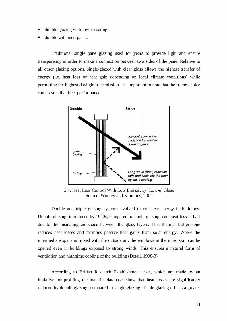
double glazing with low-e coating,
double with inert gases.
Traditional single pane glazing used for years to provide light and ensure
transparency in order to make a connection between two sides of the pane. Relative to
all other glazing options, single-glazed with clear glass allows the highest transfer of
energy (i.e. heat loss or heat gain depending on local climate conditions) while
permitting the highest daylight transmission. It’s important to note that the frame choice
can drastically affect performance.
2.4. Heat Loss Control With Low Emissivity (Low-e) Glass Source: Wooley and Kimmins, 2002
Double and triple glazing systems evolved to conserve energy in buildings.
Double-glazing, introduced by 1940s, compared to single glazing, cuts heat loss in half
due to the insulating air space between the glass layers. This thermal buffer zone
reduces heat losses and facilities passive heat gains from solar energy. Where the
intermediate space is linked with the outside air, the windows in the inner skin can be
opened even in buildings exposed to strong winds. This ensures a natural form of
ventilation and nighttime cooling of the building (Detail, 1998-3).
According to British Research Establishment tests, which are made by an
initiative for profiling the material database, show that heat losses are significantly
reduced by double-glazing, compared to single glazing. Triple glazing effects a greater

15
reduction in losses, and low emissive glazing gives further reductions in heat loss, with
low-e coated double glazing being equivalent to triple glazing (Wooley and Kimmins,
2002). Besides the technological advances in multiple glazing systems, coatings for
various aims used between double-glazing and inert gases used in cavity, to improve
their efficiency For instance, Argon and Krypton are both inert gases and they are
heavier than air, resulting in a reduction of convective heat transfer between panes of
glass.
Table. 2.3.Thermal Performance (U-value) in (W/m2K) Of Various Glazing Types
Source: Wooley and Kimmins, 2002
In order to understand glazing and ensure its benefits in a project, designer has to
know properties of glazing materials in brief. Glass has certain properties, which affect
its performance in the spectrum of solar radiation. The solar radiation energy, which
strikes to the surface of the glass, shows three types of behaviour; some goes straight
through, some is reflected outside and some is absorbed by glass. Almost all the solar
heat is carried by visible (%53) and infrared (%46) wavelengths of radiation. Absorbed
radiation includes the longer wavelengths infrared that cause the glass to heat up, while
shorter infrared wavelengths pass through into the building and strike objects, warming
them up. Therefore long wavelengths of solar radiation (IR) transforms to shorter
wavelengths (UV) after hit a surface inside.
Glazing system Thermal transmittance
U-value
Sheltered Normal Severe
Single 5.0 5.6 6.7
Double Air space
3mm 3.6 4.0 4.4
6mm 3.2 3.4 3.8
12mm 2.8 3.0 3.3
20mm (or more) 2.8 2.9 3.2
12mm low-E 1.7 1.8 1.9
Triple Air space
3mm 2.8 3.0 3.3
6mm 2.3 2.5 2.6
12mm 2.0 2.1 2.2
20mm (or more) 1.9 2.0 2.1

16
Saving energy through out windows, which is partly succeeded by glazing, is an
important issue. Thus, energy efficient glazing should allow solar heating in winter
when overall heating demand is positive, and also should prevent unwanted heating in
summer, when excessive solar gain may need mechanical cooling with consequent
energy problems.
The measure of success in energy efficiency will change due to design in every
building. For the buildings with complex energy management systems, it is impossible
to assign every savings to windows, which make up one part of an integrated system.
2.4.2. Classification According to the Form
Glasses classify as “flat glass, bent glass and block glass” according to their
form. Flat glass is the group that is used the most widely in architectural applications. It
includes sheet glass, plate glass, float glass and rolled glass. All kinds of industrial flat
glasses are obtained with two main glass production methods, which are float and
rolled.
According to Türkseven (1996), the common glass type that is used today is the
float glass. This high quality type of glass is produced by floating the melted glass on a
tin solution. By using this method, the amount of energy required reduces. Besides that,
this type of glass has put an end to all other flat glass manufacturing methods. Float
glass can be evaluated in two groups: “clear float glasses and coloured float glasses”.
Clear float glass is used in areas where the criterion of high light transmission
and visual quality are important. The important advantages of float glass are its high
optical quality and admittance of 90% of the visible light. Thus, it decreases the
artificial lighting costs by an important ratio (Lof Glass, 1990). In contrast with clear
float glass, coloured float glass is used in areas where high light transmission is not very
important but the control of solar heat gain and the emphasize of colour on the building
as an aesthetic element is necessary (Akçakoca, 1996). Coloured or clear float glasses
can be used for different purpose in buildings by using bending, coating and tempering
processes.

17
2.4.3. Classification According to the Function
Türkseven (1996) classifies glasses according to their functions as “glasses for
sun and climate control, glasses for building safety and security and decorative glasses”.
2.4.3.1. Glasses for sun and climate control
As Türkseven (1996) explained; the solar control for a building must be
considered together with the window area, orientation, shading devices and the selection
of the appropriate glass. The solar control glasses can be classified in four main
headlines: “body tinted glasses, coated glasses, insulating glass units and spandrel
glasses”.
A. Body tinted glasses: Body tinted glasses are obtained by adding colour-giving
materials to the glass mixture. These types of glasses decrease the amount of visible
light as it is absorbing the sunlight. The colour darkens as the thickness of glass
increases. In this respect, glasses have to be used at the same thickness over the entire
façade to ensure a homogeneous appearance. Body tinted glass is less reflective but
more absorbent than clear float glass. Beside this, heat-treating process has to be applied
on to the body-tinted glass to prevent its breakage due to thermal shocks, while clear
glass does not require such an extra treatment.
B. Coated glasses: These types of glasses control sun by reflecting a considerable
amount of sunbeam with their coating. Solar control performance of these glasses is
better than the body tinted glasses. When coated and body tinted glasses combined with
each other the variety and performance can be increase. Coated glasses can be examined
in two main headlines as “reflective and low-E” coated glasses.
a) Reflective coated glasses: Reflective coated glasses are obtained by applying of
metal-alloyed reflective coating on one side of clear or body-tinted glass. If it is coated
during the float process, then it is called “on line”. In another way, if it is coated after
the process, it is called “off-line” coated glass. It is important to protect the coated
surfaces against direct sunlight. The reflective glasses have higher solar control
performance and larger product and colour variety in comparison to body-tinted glasses.

18
They reflect back some of the incident sunlight and reduces the cooling costs of inner
spaces. However, these glasses decrease the amount of visible light as they beams that
strike the glazed surface. In addition to that, it is not good to use reflective glass in cold
climates under these because reflecting back the light increases the heating expenses.
b) Low-E coated glasses: These types of glasses are one of the most recent
developments of solar control and energy conservation. Low-Emissivity glasses are
obtained by the application of a very thin metal coating directly either on glass surface
or on plastic film. The most important characteristics of this kind of glass are to provide
sun and climate control while admitting most of the visible light in. According to Mays
(1989), Low-E coatings may be divided into two categories as “soft and hard”. While
soft coating is obtained by sputtering of a thin layer of silver or metal oxide on glass
surface; hard coating of this kind is obtained by the application of reflective and
ultraviolet resistant film between two layers of glass during production.
Low-E coated glasses decrease the amount of heat transfer and they increase the
R-value of glazed units. They reflect rather more but absorb more solar energy, half of
which tends to be reflected back into the internal space thus causing more efficient
warming. Such coatings reduce heat loss; by reflecting back the heat, which had turned
to longwave after hit an indoor element. Low-E coated glasses let in a reasonable
amount of solar gain, and are suitable for climates with both heating and cooling
concerns. Low solar gain Low-E glazing is ideal for buildings located in cooling-
dominated climates (www.efficientwindows.com). Therefore designer should be careful
about the usage in hot climates and south facing buildings.
According to Fisher (1985), Low-E coatings do not only transmit or reflect
different wavelengths in the solar spectrum. Manufacturers can tune the coatings to
transmit different amounts of a given wavelength. For instance, Low-E coating will
admit some shortwave infrared heat along with the visible light in cold climate
residential buildings where heat gain is desired. However, in office buildings or in
structures in warm climates where heat gain is undesirable a thicker coating will reflect
most of the shortwave heat although at the expense of some of the visible light.
19
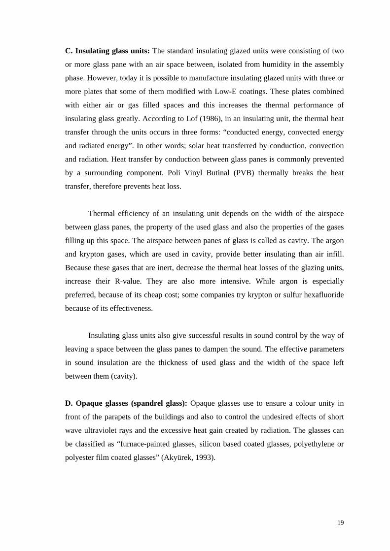
C. Insulating glass units: The standard insulating glazed units were consisting of two
or more glass pane with an air space between, isolated from humidity in the assembly
phase. However, today it is possible to manufacture insulating glazed units with three or
more plates that some of them modified with Low-E coatings. These plates combined
with either air or gas filled spaces and this increases the thermal performance of
insulating glass greatly. According to Lof (1986), in an insulating unit, the thermal heat
transfer through the units occurs in three forms: “conducted energy, convected energy
and radiated energy”. In other words; solar heat transferred by conduction, convection
and radiation. Heat transfer by conduction between glass panes is commonly prevented
by a surrounding component. Poli Vinyl Butinal (PVB) thermally breaks the heat
transfer, therefore prevents heat loss.
Thermal efficiency of an insulating unit depends on the width of the airspace
between glass panes, the property of the used glass and also the properties of the gases
filling up this space. The airspace between panes of glass is called as cavity. The argon
and krypton gases, which are used in cavity, provide better insulating than air infill.
Because these gases that are inert, decrease the thermal heat losses of the glazing units,
increase their R-value. They are also more intensive. While argon is especially
preferred, because of its cheap cost; some companies try krypton or sulfur hexafluoride
because of its effectiveness.
Insulating glass units also give successful results in sound control by the way of
leaving a space between the glass panes to dampen the sound. The effective parameters
in sound insulation are the thickness of used glass and the width of the space left
between them (cavity).
D. Opaque glasses (spandrel glass): Opaque glasses use to ensure a colour unity in
front of the parapets of the buildings and also to control the undesired effects of short
wave ultraviolet rays and the excessive heat gain created by radiation. The glasses can
be classified as “furnace-painted glasses, silicon based coated glasses, polyethylene or
polyester film coated glasses” (Akyürek, 1993).

20
2.4.3.2. Glasses for building safety and security
Ordinary glasses are not resistant to thermal tensions and strikes, they can be
easily broken and they have no fire safety. Today glass can be brought to a more secure
condition against many effects with the under various processes of current technology.
Glasses for building safety and security can be classified as “heat treated glass,
tempered glass, laminated glass, wired glass, alarm glass and fire resistant glass”.
A. Heat-treated glass: Solar control glasses absorb a considerable amount of energy
and then they warm. If glass cannot receive the solar energy to the some parts of it then
there will be a tension difference between the lighted and shaded parts on the same glass
surface. This may cause glass to break into pieces which is used widely on the exterior
walls of the buildings. So that, “heat strengthening” method has to be applied on glass
to prevent this hazardous problem. This process is based on applying a pre-tension to
glass surface by cooling it with blowing fans after it reached a certain temperature. Heat
strengthened glass also gain resistance against thermal tensions and decrease the
breakage risk. In another words, this method increases glass resistance almost twice.
However these glasses are irresistant to the strong effects and break into sharp and large
pieces so that, these glasses are not accepted as ideal safety glasses.
B. Tempered glass: The principle of obtaining tempered glass is same with heat-
strengthened glass except the fast cooling of tempered glasses. Tempering process
provides glass four or five times more resistance and glass become resistant to the
stroke effects or thermal tensions and fall apart into very small pieces, which are remain
in the frame and do not harm anybody. Tempering process provides the glass a waved
surface. Once the glass is tempered, it is impossible to cut or make changes in size.
C. Laminated glass: This type of glass is obtained by uniting two or more glass panes
with plastic based transparent layers in between them under a certain temperature. If
laminated glass is composed of two layers of glass and one layer of plastic sheet
between them, it can be used as “safety glass” against breakage. The resistance of
laminated glass unit increases as the numbers of glass and plastic layers increase. As
Krewinkel (1998) explained, the laminated safety glasses retain an adequate residual
structural strength and dampen the noise acting as an acoustical barrier as a result of the

21
strong elastic bonding of the PVB film. However the amount of light transmission
property is not very different from the ordinary glass. In addition to that, while
laminated glass is resistant to spot effective breakages, tempered glass is more
successful to meet the surface effective strokes.
D. Wired glass: Wired glass is produced by sandwiching steel wire between two glass
layers and obtained by the rolling process. Wired glass is resistant to stroke, fire and
pressure effects. It breaks into the pieces against the effects of stroke and heat, but does
not spread out because of the wire net in it.
E. Alarm glass: Alarm glass is an improved version of wired glass and used against
attacks. This type of glasses obtained by placing 0.1 mm thickness of wires in glass to
form an electrical circuit. This circuit is broken setting of an alarm when the glass is
broken.
F. Fire resistant glasses: Fire resistant glass has 60 and 90 minute fire rating. It
encapsulates a transparent polymer gel between two layers of tempered glass. As Fisher
(1985) explained, when the temperature in a room reaches about 7000 F, the gel
separates from the glass surface exposed to the fire; at about 8000 F to 9000 F. The
tempered glass shatters and the gel turns opaque and its water content evaporate a
process that absorbs a great deal of heat and thus protects the other layer of tempered
glass.
2.4.3.3. Decorative glasses: Glasses can also be used as a decorative element by the
help of its aesthetical appearance. Decorative glasses can be classified as “mirror glass,
obscured glass and glass blocks”. Obscured glass is also obtained by methods of
“patterning, surface treating and printing” application way. The desired texture can be
given to them with these methods.
2.5. Environmental Control Criteria Of Glass Glazing Systems
Glass is the most practical and common used material among its alternatives
because of its work performance and maximum use of area on the buildings. The
application of glass as a building skin increases the inner space utilization because of

22
providing economy on climatization, which is an important management expense.
Energy efficient houses with glass annexes are good examples of this kind of usage.
The properties of glass can be varied and regulated by modifying the
composition and production techniques as explained in previous chapters. Glass
coverage has to carry the responsibilities of building; to make the buildings sheltered for
every environmental effect and to control the effects of light, vision, solar heat, wind,
physical and chemical corrosion, noise, robbery beyond its traditional use as window. In
the further sections, glass performance assessed by four basic environmental control
criteria in terms of constructional physics: optical, thermal, acoustic, and safety.
2.5.1. Light Transmission Control
Light and vision control are important criteria for glass glazing that is used on
building skin. While low light transmission cause insufficient interior illumination and
thus, require artificial lighting even in the daytime; the high light transmission cause
excessive brightness and it destroys the homogeneous appearance of glazed building.
The selected glass should balance the negative effects with the optimum desired light
amount. Glass can also change colour and modify the transmission of light; and with the
use of liquid crystals, it can be made transparent or translucent.
Heat Transmission
CoefficientDay Light
Transmission Solar Energy Transmission
PRODUCTS / cavity 6mm 9mm 12mm
Isıcam Standard 3,3 3 2,8 78% 70%
Isıcam Comfort 2,5 2 1,7 70% 46%
Table 2.4. Heat Transmission Coefficients And Day Light And Solar Energy Rates Of Glasses
Source: www.yasasan.com
When a beam of light falls on the surface of glass pane, some of the light is
reflected from the glass surface, some of the light passes through the glass, and some is
absorbed in the glass. While the measure of the proportion of light reflected light from
the surface is called “reflectance”, the measure of the proportion absorbed is the

23
“absorptance” and the measure of the proportion transmitted is the” transmittance”.
Each quality is expressed as a fraction of the total quantity of light in the beam. If the
intensity of the beam is represented by the numerical 1, reflectance by R, absorptance
by A and transmittance by T, intensity may be expressed as follows: R + A + T = 1
(www.cmog.org)
Reflectance from a glass surface can be regulated by coatings applied to the
surface. A metallic coating will produce the maximum reflectance. Other coatings show
selective reflectance, such as the heat-shielding glass that reflects a high proportion of
infrared but transmits a high proportion of visible light. Still other coatings eliminate
reflectance almost completely such non-reflective coatings are commonly used on
lenses (www.cmog.org).
Optical properties are concerned with the behaviour of glass toward light, the
visible spectrum that extends like the rainbow from violet on one end to red on the
other. However optical refers also to behaviour towards the infrared and ultraviolet
regions of spectrum. The greatest physical difference between these bands of energy
spectrum is in the wavelength. Ultraviolet waves are shorter than visible waves and
visible waves are shorter than infrared. All of them are so short that extremely small
units are used in measuring them (www.cmog.org).
2.5.2. Thermal transmission control
Solar energy control is another responsibility expected from glass. An efficient
glass should prevent excessive heat gain as admits the maximum amount of light in.
According to Demetri, (1996), significant energy savings are more likely to come from
new glazing technology, and the use of ventilated cavities within triple glazed systems,
and improvements to framing systems. With the improvements in glazing technology
and the decrease of loss to minimum through connection points make glass to reach an
ideal performance.
As it is known, the solar energy strike to the glass surface is reflected back,
admitted it, or is converted into heat as being absorbed by glass. Low-E coatings may
keep the longwave radiation after transmitted through glass, thus may protect heat loss.

24

25
Commercially available insulating glass glazing units’ thermal transmission
coefficient chance between 1.7 / 3.2 W/m2K depending on the temperature (Isıcam). As
Türkseven (1996) explained, the light transmission and solar heat transmission are not
directly proportional with each other. Light transmission rates of the glass panes are
given for the visible light spectrum, where the solar heat gain is calculated from the
whole spectrum. The wavelengths of visible light and infrared light, which are both
responsible for the heating, are different from each other in the solar spectrum. As the
ratio of the light transmission coefficient rises, the success of the solar control glass
increases along with it.
Glass is the leading element in insulation and energy conservation.
Developments on photochromic, thermochromic and electrochromic glass plates
showed that, improved glass can adapt itself according to the climate and air conditions
like a chameleon. Photochromic glass is used in solar panels for the conversion of
sunlight into electricity. Electrochromic glass can be made to change from clear to
coloured (and also opaque) when a mild electric current is applied to it. It provides all
kinds of insulation perfectly and presents the best comfort to the user at optimum
(Demetri, 1996).
2.5.3. Acoustical control
Light structures, such as glass glazing systems, let sound to pass easily through
building when compared to the heavy and load bearing walls. So that acoustical
insulation is another responsibility that glass has to provide as a building skin. There
should be precautions not only taken by glass but also taken by frames and installation
elements. The practical precautions that can be taken by glass can be listed as below:
to leave a space between the glass panes to dampen the sound and to coat
the sides in between by sound absorbing material.
to use insulating glass units and laminated glasses combined with special
resins
to increase the thickness of glass, by using multilayered insulation glass
and pvb combined laminated glass (Lof, 1987).

26
The thickness of glass used and the width of the space left between them are
effective parameters in sound insulation. As these parameters increase the sound
insulation value also increases, up to a definite value. Approximately 20cm cavity
between panes of 6mm ordinary glass provides up to 41dB reduction, which saves the
best reduction performance. Addition to the list of improvements given above,
particular gases (SP6) can be useful to dampen sound as an infill. In section 5.1.3.
acoustical performance of glass types (sound reduction index) are given as a table.
2.5.4. Safety and security control
Glass takes the responsibility of providing a safety and security line for the
buildings. Safety and security properties deal with the action of forces on a material and
the effects that these forces produce within the material. There are three types of forces
to be considered: “a tensile force exerts a pull on the material”, “a compressive force
acts to squeeze the material” and “a shear force acts on the material in a manner similar
to a pair of shears to slide one part of the material in one direction and another in the
opposite direction”. Tensile forces, which are the most important in glass, give rise to
tensile strain within the glass and glass breaks only from tensile tension.
(www.cmog.org).
Mechanical hardness of glass is a complex phenomenon that is not completely
understood. It can be measured by three methods: “scratch, penetration and abrasion”.
Strength of glass is only slightly affected by composition but is highly dependent on this
surface condition. Strength is measured in the laboratory by applying a bending load to
a bar of glass until the bar breaks. The break originates in the lower surface since glass
always fails from tension. (www.cmog.org).
Especially tempered and laminated glasses resistances against strokes and
thermal tensions are high. If laminated glass is composed of two layers of glass and one
layer of plastic sheet between them, it can be used as safety glass against breakage. The
resistance of laminated glass depends on the numbers of glass and plastic layers. Fire
resistance of glass is also important in terms of security. Especially wired glass and
glass block have been used for years for fire resistance. But the choices have been
increased along with the improved technology.
27
Glass can also be strengthened by several ways of chemical means. One of the
most commonly used requires an exchange of ions in the glass surface and another
method is laminate strengthening process. In the first method, the glass is immersed in a
molten salt both and large ions migrate into the surface, replacing smaller ions. This
action crowds the surface and produces compression. In laminate strengthening method,
the product is made of a sandwich glasses and the inner glass shrinks more on cooling,
causing the outer layer to be put into compression (www.cmog.org).
Pre-stressing process of the glass is often done by thermal tempering, which
causes a wavy appearance on the surface of the plate. It is possible to temper the plate
partially. But semi tempered glasses are out of the security glass list, because of the big
plates obtained that can be harmful when broken. In the tempering process, first the
glass is heated to the point of almost sagging under its own weight, and then it is chilled
suddenly. A large temperature difference exists between the surfaces and interior
because of low thermal conductivity. When pre-stress is applied there will be an equal
amount of tension somewhere to maintain the balance. This tension is buried in the
middle of the glass where it is safe from damage protected by the outer skin of
compressed glass (www.cmog.org).

Table.2.5. The Comparative Performance Values Of Isıcam Samples, 2003 Source: www.yasasan.com
Products
Day Light Solar Energy Thermal Transmission
Coefficient (K veya U)
Relative Heat Gain (W/m2)
Transmittence%
Reflectance Outdoors
%
Reflectance Outdoors
% Absorbition
% Direct
Transmittence%
Total Transmittence
Shading Coefficient
ISO 9050W/m2K
ASHARE (W/m2K)
Winter Summer
78 14 11 29 60 ,69 ,81 2,8 2,8 3,2 533
73 11 17 38 45 ,54 ,63 1,8 1,8 1,9 414
38 9 8 62 30 ,42 ,49 2,8 2,7 3,2 332
36 9 10 67 23 ,34 ,40 1,8 1,8 2,0 268
70 13 24 36 40 ,46 ,54 1,7 1,7 1,8 355
Chapter 3
INVESTIGATION OF THE INFLATABLE PILLOW SYSTEMS
Glazing which has been discussed in previous chapter is one of the major
components of the buildings. Traditional glazing commonly depends on the use of glass
and its properties. In order to upgrade its environmental properties glazing systems are
evaluated. However contemporary architecture exploits existing or new materials with
increased performances. Plastics, architectural fabrics and their combinations are
developed in terms of cladding that can be determined also glazing in specific cases.
Plastics which consist of a combination of various polymer types, did gain an
increasing importance as a building material in contemporary architecture. They have
found a wider application area than before. Technological improvements and new
processes in industry upgraded plastics, in terms of their properties and performance.
They have reached to the surface qualities of glass. Form free and lightweight natures of
the plastics are two basic advantages against traditional glazing (Detail, 2002/12). But,
true potential of the plastics is seldom exploited in architectural applications. Since the
1980’s, transparent and diaphanous plastic semi-finished sheet products have been used
for the skins of many buildings, allowing light to enter by day and to radiate out at
night.
Architectural fabrics used also as a cladding solution in specific buildings.
Architectural fabrics and membranes are produced in various types with special
coatings to provide better environmental control properties. Coated fabrics have
inherent strength sufficient for them to be used as self-supporting, pre-tensioned roof
membranes.
The basic need for a membrane application is the need of high light gain into the
structure. The need of light transformed membrane cladding to glazing in many cases.
However, light transmission values achieved with fabrics are very low. Therefore, in
terms of a better light transmittance the ideal solution would be a clear foil without
fabric support. Furthermore, due to low thermal performance of membrane structures,
multilayered systems are formed with inflated structures. As Watts (2001) explains that

air supported fabric roofs are used to cover large areas that require a degree of
transparency together with high thermal insulation. Development of pneumatic systems
and other structural systems has improved the inflatable applications. Festo Seminar
Hall in figure 3.1. , is a new generation inflatable structure where the human analogy is
made by extrapolating tendons and muscles and where intelligent pneumatics are used.
In the line with these developments, inflatable systems are still the subject of researches
with the awareness of the performance of inflated structures depends on the usage,
material property and number of layers.
Today Ethylene Tetrafluoroethylene (ETFE), which is a polymer, assumed a
major importance in membrane and inflatable constructions. It can be translucent or
transparent and it can also be coated. Because ETFE foils have no inner fabric layer to
give them strength, they are not capable of covering large areas unsupported. Therefore,
to form large spanning areas, the foil must be supported by a sub-structure of arches,
beams or cables, which divides the foil into panels. Inflating multilayered ETFE
membranes are relatively new solution in terms of glazing.
Fig. 3.1. Festo Group Inflated Seminar Hall Designed with Human Analogy Source: www. festo.com
3.1. Definition Of Inflatable Pillow System
The Inflatable Pillow System (IPS) developed for the roofing and cladding
applications. It is a glazing solution for those claddings that have been used for a decade

in architectural applications. Instead of other glazing systems like curtain walls and
rooflights that are made of glass and glass glazing systems, this chapter is objected to
investigate inflatable pillow systems and its potential. Inflatable Pillow Systems are
principally pneumatic structures taking name from their pillow form. IPS can be defined
as “Pneumatically Supported Multilayer Membrane Systems” made of a modified co-
polymer called ethylene-tetra-fluoro-ethylene (ETFE). Robinson- Gayle et.al. describes
the ETFE pillows as; it is a multilayered system that consists of several layers of ETFE
foil which is heat-sealed and clamped in a frame in order to top up with a small pump
intermittently.
Fig. 3.2. ETFE Chemical Formula – (ethylene- tetra fluoro ethylene) Source: www.texlon.ch
IPS inherits the common characteristics of the inflatable systems, which is a part
of pneumatic systems. Besides this, because of the glazing material is a membrane it has
the properties of membrane structure. Because of the lightweight nature of the foil, this
system can be defined as among other lightweight systems. Furthermore, this system
has been determined as an energy efficient cladding technology or as the climatic
envelope according to its environmental properties.
Fig. 3.3. Transparent and Dotted ETFE Sheets Source: www.covertex.com
ETFE foil that is preferred for pillow construction is a synthetic sheeting or film;
a new generation membrane. Isotropic film or sheeting exhibits a tension-stretching
behaviour that is virtually equal in all directions. Of the many kinds of synthetic
sheeting that are available, two groups of thermoplastic materials are of special

importance in membrane construction: fluoropolymer sheeting (mainly ETFE and THV)
and polyvinyl-chloride sheeting (PVC) (www.covertex.com).
Thin fabrics generally don’t provide adequate thermal and sound insulation. But
multilayer systems can make it possible. In other words fabric systems that have
appropriate thermal insulation and light transmittance, could be possible with only
pneumatically supported multilayer membrane systems, made of ETFE. However these
pillow systems could be assembled with another type of ethylene foil, PTFE that have
been previously used for several applications in architecture. PTFE is generally known
as Teflon trademark. It has been also used as a topcoat on architectural fabrics.
Among many synthetic sheeting ETFE foil has better biaxial tensile properties.
It is an almost isotropic film that shows virtually same structural behavior in every
direction, while many of the woven fabrics are considered as anisotropic materials.
ETFE foils that are manufactured in roll of sheets cut out to form pillows with special
methods. IPS can be assembled between two to five layers. Multilayered foil joined
together at the edges and inflated to form a sealed pillow. Held within a support frame,
these panels can be used as glazing. The internal pressure pre stresses the foil and
enables it to resist the loads as wind and snow.
In various sources it can be seen that the synonym of the term pillow can be
replaced by cushion, which is not wrong. But in present study, the system will be called
as pillow systems, instead of inflated cushion systems.
3.2. Evolution Of The Pillow System
Inflatable pillow system applications have been effectively impressed by various
constructional improvements. Although ETFE has been known for more than 50 years,
it has not been fully exploited by the construction sector. Developments in structural
systems like tension structures and pneumatic structures have affected pillow systems.
Researches on architectural membranes have resulted as better materials, and systems,
which are essential for pillow system. Those innovations motivated air supported and
inflatable structure applications mostly in 70s. Furthermore, in the 1960’s and 70’s
plastics and other synthetic materials did gain a certain importance in building, but they
soon left their place as a result of their inappropriate application or technical
deficiencies.
In other words, the evolution of the recent system depends on developments of
many fields related with engineering and material sciences as briefly explained in the
domain of the study.
One of the early examples of the foil pillows as transparent cladding was on the
giant space frame at Expo’70 in Osaka, Japan. The structure designed by the architect
Kenzo Tange and engineer Prof. Kawaguchi. These pillows were made from polyester
foil, which has excellent tension properties but low tear strength and grades in sunlight.
Since then, fluoropolymer foils have been developed with better properties.
Dr. Herbert Fritz who is a retired polymerchemist of Hoechst AG. introduces
himself as the inventor of the ETFE in 1976. He explains that the basic idea for
producing the film was to use it as a solar collector and later on as a long lasting
membrane material for buildings. (www.eden-project.co.uk)
In 1977, engineer David Geiger began investigating pillow systems as solar
control systems. He had studied the use of three layer membranes as solar collectors.
The upper and middle membranes are both split: the south facing half of the upper
membrane is transmissive, the north facing half reflective and the south facing half of
the middle membrane reflective, north-facing half transmissive. During the summer the
solar cell is closed and the air layer between membranes is inflated so that the middle
membrane rests against the upper membrane, making a continuous reflective surface
that reduces heat load. During the winter the cell is open; the middle membrane rests
against the lower membrane, and solar energy absorbed by the cell can be radiated or
conducted to the space below.
In addition to those developments, pillow systems have been used for optimizing
internal climate control. For the Florida Junior collage at Jacksonville, similar solar
cells were proposed to dehumidify interior air. Air warmed by the cells is passed
through silica gel, where it losses enough moisture that, when mixed with air intake the
desired moisture level is obtained. The silica gel is dried by additional hot air from the

solar cells, which is pumped through the gel and evacuated outside. According to
Robbin T. (1996) such opportunities to use membrane cells as heating and cooling
machines have been neither fully tested nor implemented.
Fig. 3.4. David Geiger’s Air Pillows As Solar Cells Source: Robbin T., 1996
In 1981, in a collaborative project, Buro Happold, Arne Fullerton and Frei Otto
developed a design using inflated cushions of a fluoro-polymer foil such as a cladding
to a 14 ha air supported structure top enclose a township at 58 o N in Alberta, Canada.
Since that time foil pillow systems have been used successfully on projects worldwide.
Architect Volker Giencke’s greenhouse structure in the botanical garden of Graz
University (1982-93) is also a forerunner of this line of development. It comprises an
aluminium structure, the arches of which follow the lines of thrust, and it is covered
with multilayer acrylic sheets curved in two planes. Transparent acrylic panels with
double curvature used as glazing in order to improve thermal insulation. Hollow
structural sections are used as heating radiators. All four glasshouses share the same

technology and control systems. The parabolic structure is built in aluminium supported
with steel cables. Double curved acrylic sheets achieve a 98 percent light transmission,
the highest so far achieved internationally (A.Review, 1996/10)
Fig. 3.5. Graz Greenhouse by Volker Giencke Source: Architectural Review, 1996/10
In 1983, Foiltec Company designed a zoo in Arnheim, Holland, which was
created as the only self-sustaining man made ecology. This early IPS project was a
cable suspended structure. Arnheim Zoo, which is also known as the Burger Zoo, is one
of the longest lasting ecological systems to function trouble-free. Foils are chosen to
create the ideal roofing and cladding system for simulated environments, allowing a
large section of the UV (ultraviolet) spectrum to be transmitted.
Fig. 3.6.Arnheim Zoo Roof Source: www.foiltec.com

Since it has been presented as a zoo and botanical garden glazing system at the
beginning of 80’s, IPS has proven its performance in many cases with various needs.
Framing and clamping systems, has developed for bespoke systems, which has
accelerated its commercial applicability as glazing or a total building envelope. It has
been subsequently used in various buildings predominantly in the UK and Germany.
3.3. Components and The Structure Of IPS
IPS structure consists of pneumatic pillows re-strained commonly in aluminium
extrusions and supported by a lightweight structure. The pillows are manufactured from
between two and five layers of a modified co-polymer called ethylene-tetra-fluoro-
ethylene (ETFE). The pillows are inflated with low-pressure air between 200-1000 Pa
(200-1000 N/m2) to provide insulation and resist wind and snow loads. Therefore it’s
possible to investigate system in three sections, according to its components;
Glazing, which is maintained by pillows,
Frame structure and supporting elements,
Other subsidiary equipments needed for inflation.
Fig. 3.7.Triple Layer Foil Construction Scheme
This cladding system comprises a number of foils of a UV stable fluoro-polymer
ETFE welded into pillows. The pillows are restrained around their perimeter by
aluminium extrusions, which are in turn fastened to a supporting primary structure. A
pillow comprises at least two foils, however more foils can be added into the system to
enhance the claddings’ insulation properties.
The pillows can be fabricated in any size or shape with limiting factor being the
wind and snow loads that the cladding has to resist. Pillows can be manufactured in
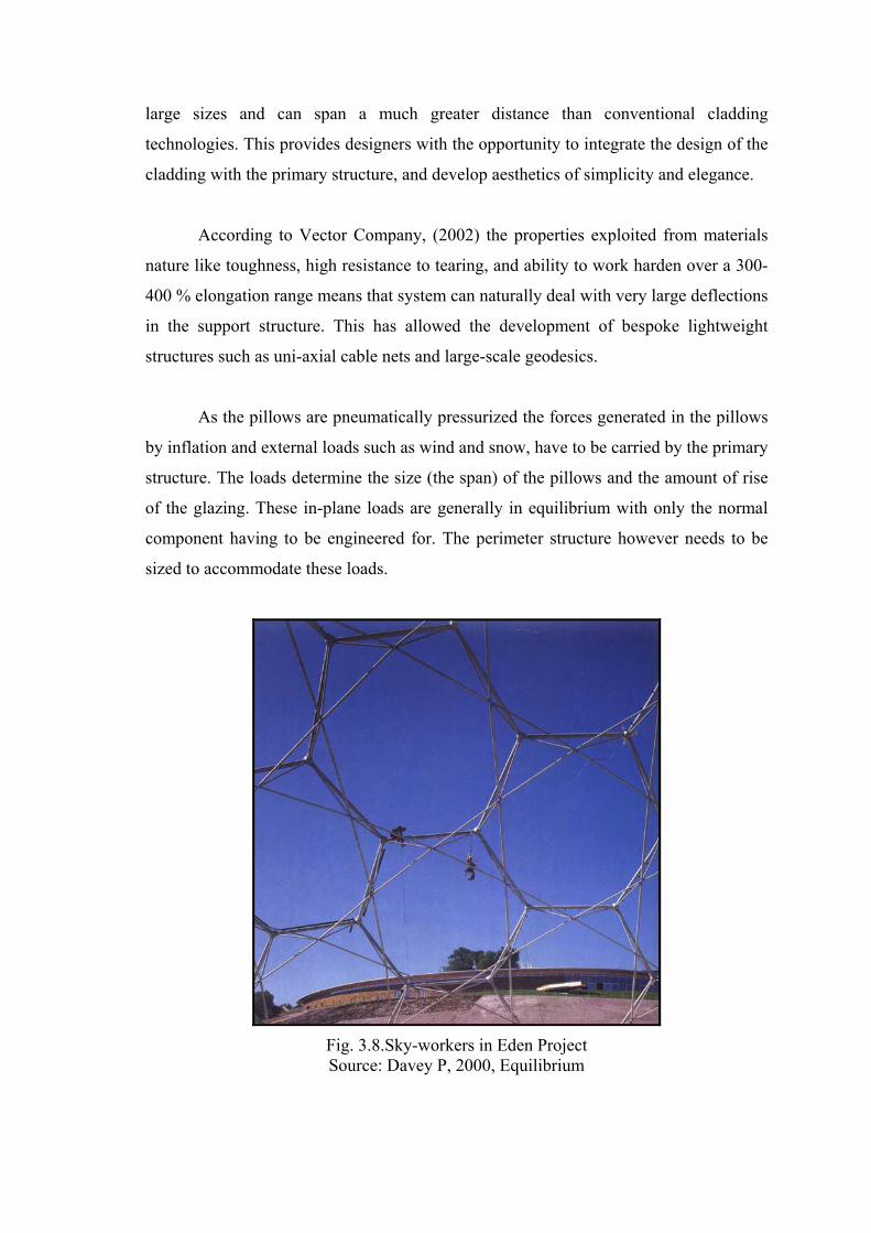
large sizes and can span a much greater distance than conventional cladding
technologies. This provides designers with the opportunity to integrate the design of the
cladding with the primary structure, and develop aesthetics of simplicity and elegance.
According to Vector Company, (2002) the properties exploited from materials
nature like toughness, high resistance to tearing, and ability to work harden over a 300-
400 % elongation range means that system can naturally deal with very large deflections
in the support structure. This has allowed the development of bespoke lightweight
structures such as uni-axial cable nets and large-scale geodesics.
As the pillows are pneumatically pressurized the forces generated in the pillows
by inflation and external loads such as wind and snow, have to be carried by the primary
structure. The loads determine the size (the span) of the pillows and the amount of rise
of the glazing. These in-plane loads are generally in equilibrium with only the normal
component having to be engineered for. The perimeter structure however needs to be
sized to accommodate these loads.
Fig. 3.8.Sky-workers in Eden Project Source: Davey P, 2000, Equilibrium

This system can also accept virtually all building movements, and thus one can
design structures, which have much greater deflections than other cladding technologies
permit. Pillows confront some of the planeloads and wind load. Thus, their effects to the
structural system are reduced which affects not only to the cladding or roof structure but
also whole structure including the foundations.
As other cladding and glazing solutions in the market design and engineering of
the pillow system is a very specialist area in terms of the materials’ quality and
performance. In order to have the most benefit of the system, and to ensure that the
structural grid and cladding interface is optimised, designers and engineers should get
an early consultation in the development of design phase.
3.3.1. Glazing (Pillows)
The performance of the IPS depends on the pillow form and the material used as
glazing in the system. As determined before, ETFE is a thermoplastic copolymer
derived from the polymerization of the Ethylene and Tetrafluoroethylene (Teflon®)
monomers (www.crestcoating.com). This membrane material used for buildings is not a
woven fabric but a foil; a polymer film sheet, usually formed into inflated pillows.
Although investigated and used for several decades, foils have become truly useful for
the first time with the introduction of an ETFE foil, a partly crystalline plastic.
Plastic sheeting, as used in architecture today, allows creation of the building
skin that are unique in their permeability to light and UV radiation. ETFE has proved
most effective in this context. Its extremely low weight (350 g/m2 for a thickness of 200
um), its high permeability to light, its great chemical resistance to acids and alkalis, its
relatively long life (more than 20 years without significant change in its mechanical and
optical properties) and its almost complete recyclability make fluoropolymer sheeting
most valuable and economical building material. (Karsten, 2002)
To ensure that a thin membrane transmits the various directional loads to which
it is subject solely in the form of tensile stresses and without folding, a prestressing
process is necessary.
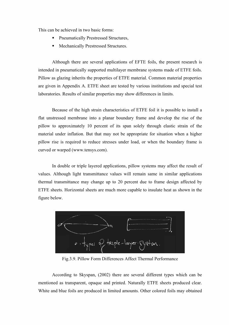
This can be achieved in two basic forms:
Pneumatically Prestressed Structures,
Mechanically Prestressed Structures.
Although there are several applications of EFTE foils, the present research is
intended in pneumatically supported multilayer membrane systems made of ETFE foils.
Pillow as glazing inherits the properties of ETFE material. Common material properties
are given in Appendix A. ETFE sheet are tested by various institutions and special test
laboratories. Results of similar properties may show differences in limits.
Because of the high strain characteristics of ETFE foil it is possible to install a
flat unstressed membrane into a planar boundary frame and develop the rise of the
pillow to approximately 10 percent of its span solely through elastic strain of the
material under inflation. But that may not be appropriate for situation when a higher
pillow rise is required to reduce stresses under load, or when the boundary frame is
curved or warped (www.tensys.com).
In double or triple layered applications, pillow systems may affect the result of
values. Although light transmittance values will remain same in similar applications
thermal transmittance may change up to 20 percent due to frame design affected by
ETFE sheets. Horizontal sheets are much more capable to insulate heat as shown in the
figure below.
Fig.3.9. Pillow Form Differences Affect Thermal Performance
According to Skyspan, (2002) there are several different types which can be
mentioned as transparent, opaque and printed. Naturally ETFE sheets produced clear.
White and blue foils are produced in limited amounts. Other colored foils may obtained

upon request. Common uses of triple layered pillow are, white clear white, white white
white, white clear clear. Other alternatives are available related with the needs of
design. Printed foils are used commonly for triple layered pillows with variable shading
option. Prints can be applied as color or silver patterns.
An important point about the forming of the pillow structure is the load analysis
and wind pressure tests. Under load analysis the variation of pressure within the pillow
must be considered, especially for load cases with a combination of wind pressures and
suctions. It can be specified either constant pressure, constant volume or constant mass
of air within a closed cell during its 3D finite element analysis (www.tensys.com).
ETFE has an optimal welding property, but because of the excellent tear strength
mechanical connection possibilities like sewing, clamping, nailing, riveting are
compatible for stabile roof constructions. In membrane constructions welding capability
of the fabric is a very important issue in terms of economy. When welding is not
possible, membranes have to be joined by sewn seams or expensive metal joints. For
instance another fluoropolymer film PTFE (generally known with its trade name
Teflon) is used as coating on the top of architectural fabrics. But, its high melting point,
which is 327oC, makes welding process almost impossible for most of the applications.
According to Nowofol Co. thicker materials suffer problems with the thinning of the
foil near the joint. For this reason producers prefer to limit the thickness to less than 200
microns.
Inflation of Each pillow in Eden Project, which is 75m2 at maximum, takes
between 15 minutes to 3 hours to install. (www.arup.com) In the case of Festo HQ,
Transition of the pillows takes 6 minutes to be fully completed. Inflation time of the
pillows depends on the power of the inflation units and size of the pillows used.

Fig. 3.12. Elongation Tests of ETFE Source: www.vector-foiltec.com
Fig. 3.13. Pressure Tests of ETFE Source: www.vector-foiltec.com

3.3.2. Supporting Elements of IPS
Pillow structures consist of at least two membrane layers, with the intermediate
space inflated to a slight excess pressure (usually about 200 to 1000 pascals) to provide
stability. That obtains the structure to be very lightweight that shapes the structure
underneath. Pillow systems with made of ETFE sheets are different than those of
pneumatic structure, which have been used commonly in 70’s. Typically system works
similar to other conventional frame and clamping systems. The type of clamping
mechanism varies but most commonly consist of special aluminium boundary profiles,
which are supported by steel or timber substructures or cable nets. Like the most
lightweight systems, the forces in the pneumatic system need to be resisted by a support
structure. The resulting loads are a function of the shape of the foil and applied loads.
However adjacent foils tend to balance out the loads generated by the shape of the foil
itself, with the supporting structure needing to be designed to resist any applied loads
such as wind. Thus, the underneath structure and perimeter structure has to resist the
forces occurred by pillows and the lateral wind loads. This may cause the need for an
extra support by cable in the center of the pillow construction. So that, in terms of a
failure in the structure and unexpected increase in applied load for a short time, that
may be useful for the structure and the pillows. According to Watts, (2001) a very light
net integrated to design, often incorporated on the inner surfaace of the material to
withstand very high snow loads. As shown in figure of the Westminster Chelsea
Hospital Roof Detail, cables may be used under pillow structure connected to the
clamps. Diameter of the steel cables may vary according to the need of the design.
Pillows, among the structure can be virtually manufactured in any size and the
shape. Structure is not a dominant factor for the shape of construction. However the
limiting factors of the pillow size is the wind and the snow. As the pillows are very
lightweight structure should only need the be support its of weight. But like other
lightweight systems, the structure is prone to deflection. The flexible nature of the
system causes to absorb some of the structural movements by the pillows. In those
cases, pillows work as movement joints that allow the entire structure move in limits
without any collapse in the structure. According to the design this may be exploited by
underneath structure. However applied loads such as snow, needs a special care in

design of supporting structure. Although it can be carried by pillows, under excessive
loads top layer may invert allowing all the layers act under in tension.
In view of the limited load-bearing strength of the membrane, the maximum
span of a pneumatic element is about 4.5 m in the case of elongated forms and roughly
7.5 m for circular or square elements. Larger spans require additional support in the
form of beams, trusses and cables or cable nets. The membrane material is not a woven
fabric, which was previously used in inflatable structures. Therefore mechanical
properties of the membrane need to be supported periodically according to the
opportunities of design. ETFE foil is used commonly for its transparent nature as a
cladding above cable structures. In case of Hampshire tennis court a uni-axial cable net
supports 6000m2 of white ETFE pillows. It has constitutes a huge glazing in order to
take skylight in the form of cladding.
Fig. 3.14. Hellabrun Zoo - Lion Zoo Source: www.pfeifer.de
In the case of lion house in Hellabrum Zoo, Munich, for instance the pneumatic
elements are spanned between a prestressed cable net. The flexible nature of the pillows
increase architectural applicability for non-planar applications. The usage of the pillow
structure is like a high performance membrane cladding rather than a glazing. Another
striking example is the Eden Project in England, where the domes, with spans of 130m
at its maximum, consist of ETFE pneumatic elements of different sizes partly supported
by a cable network. The Masaola Rainforest house in Zurich zoo has an arched roof
with pneumatic elements up to 106m in length (probably the longest in the world) and

spanning a distance of roughly 4m. Besides Masaola Rainforest House, at Kings
hospital atrium 26m clear span is obtained with 3.6m wide pillows. In Magdeburg
Leisure pool IPS used in 30m clear span without extra support. A good example of the
use of ETFE membranes in the construction of the swimming pools can be found in the
new arched roof over the modernized Moby Dick Bath in Rülzheim (Karsten , 2002).
Rather than the structural choice, system can be used in collaboration with any
structural material that may hold the structure up. Clamps and frames that surround the
ETFE pillow are generally made of aluminium and steel. Therefore frames may be
connected to the load bearing elements of the structure.
Fig. 3.15. Various Supporting Element Choices For IPS Source: Texlon, 2003
Modular system of the IPS, reduces the initial installation cost, saves time in the
construction site. In order to get excellent form-free application opportunities of IPS,
envelope could be conceived in various frame sizes, which will affect production time
and cost. ETFE Pillows can be tailored in any size and shape with limiting factor being
the wind and snow loads that the cladding has to resist. It is also suitable for lightweight
canopies and cantilevered applications.
According to Buitink-Technology, the profiles used are made of corrosion proof
aluminium alloy. The sealing profiles that are UV and waterproof and weather proof
retain their elasticity. In order to prevent corrosion designer should be aware of
aluminium frames are capable of corrosion when connected to steel. To ensure
corrosion proof nature, substructure should be stainless steel or properly galvanized
steel.
3.3.3. Other Components of IPS
An inflation system is required to maintain the pillows at a constant pressure of
between 200-1000N/m2. This may achieved using centrifugal fans with backward
curved aerofoil blades. These centrifugal fans with humidity controls and filters prevent
moisture and dirt from entering to the pillows. The characteristics of such fans ensure a
reasonably constant pressure over a range of air flow rates. This helps to ensure a fairly
constant air pressure even when the flow rate increases to compensate for unplanned
leaks. More complex centrifugal fans can also be linked to sensors that would allow the
inflation system to vary the internal pressure of the pillows to handle with applied loads.
According to Tanno, (1997) who was a Façade engineer of Buro Happold, air inflation
is provided by means of low power electrical fans connected to the pillows via a
network of flexible pipes. Fans are simple units consisting of a running fan and a stand-
by fan. One of the motors is rated 220 Watts and is permanently on standby whilst the
other, rated at 100 Watts, is switched on and off by a pressure switch connected to a
reference pillow. The main blower is thus only operating for approximately 50 percent
of the time with power usage being in the order of 50 Watts. Fans are normally
equipped with a gauge and electronic switch that monitors air pressure in the pillows
and allows the fan to run automatically to top up pressure in the foils if it is not at the
desired level. According to Skyspan, (2002) generally an area under 250m2 only one
fan is required. Two fans are normally used per 1000m2 of foils system.
Other system requirements are air pipes and their connection accessories. The
amount of pressure in pillows depends on the climate and the frame size. The pressure
size may change by the click of a switch or it may be used in accordance with sensors.
These sensor, as a part of building automation systems, can arrange the previously
determined climatic conditions inside. By adapting sensors in to the system a partial
intelligence will be obtained. That may also save environmental responsiveness to the
building. PV solar batteries save the energy needed for the fans.
Polat, (2003) who is a representative of the Switzerland based firm; Texlon,
explains that each inflation unit contains two compressors with auto-change – over to
provide complete security. Robinson-Gayle et.al discusses that these electric fans has a
consumption of almost 50 Watts for 1000m2.

Fig. 3.16. Inflation Equipments Mounted On Roof Structure
Source: Texlon, 2003
According to Gill C. of Buro Happold for one of the early examples;
Westminster Chelsea Hospital Roof, each fan has a power requirement of around 100
Watts. In case of Eden Project fans are running half of the day and they have an
electricity consumption of 100W in 1000m2. As in Eden Project Solar collectors;
photovoltaics could be added to the system in order to save electricity from solar
radiation.
Fig. 3.17. Checkerboard Patterned Pillow And Inflating Equipments Source: Buitink-Technology, 2002
In an event of an explosion of a pillow, system goes on working properly. This
may obtain by using one-way pneumatic valves. These new generation valves called as
intelligent valves. These valves will be able keep the air inside the pillow by their
structure. That will save time to the user for the repair before the pillows are over
affected by climatic conditions.

In variable shading system, which can be used only in three layer applications,
needs same equipments but in a different working concept. Pneumatic systems are much
more complex than standard triple layered pillow systems. Both chambers of the pillow
designed to have different pressure amounts if needed. Therefore perforated sheet in the
middle of the standard three layered pillows are no longer exist. According to the
situation, mid layer can have tensile stress when the pressure in the chambers is not
equal. There is an extra air pipe for the other chamber that directly goes in to it.
Fig. 3.18. Moducel LKS Air Handling Units provided by Eaton-Williams Co. Source: www.eaton-williams.com
Fig. 3.19. Centrifugal Fans of Eden Project Source: www.edenproject.com

3.4. Classification of Inflatable Pillow System Types
In order to explain the system that is introduced above, classifications are made;
according to the number of membrane layers of the system uses, according to the
primary supporting structure and according to the form and the function in the following
chapters.
3.4.1. Classification According To The Number of Membrane Layers
The IPS forms from two to five layers. Although it is possible to make a
construction with 4 and 5 layers, because of the feasibility of the designs, it is not
recommended and implicated until present study carried out.
The common applications are categorized as follows:
Single layer applications
Double layer applications
Triple layer applications
Triple layer applications with variable shading technology
Membranes in single-layer construction are drawn taut to their edges, where
they are fixed and mechanically tensioned. In view of the lower load-bearing strength of
ETFE sheeting in comparison with woven fabric, the use of the former is limited to
relatively small structures. Larger areas can be covered with ETFE membranes if
additional intermediate supports are provided. The membrane roof at the Walchensee
Power Station in Kochel is the largest ETFE structure of this kind of existence. (Barthel,
2002)
The German Federal Environment Foundation, in Osnabrück completed in 2002,
is also covered with a single layer ETFE membrane. According to Barthel, the
lightweight nature and high light transmittance of the foil exploited by the designer in
order to obtain an outdoor ambiance in the ventilated atrium. Ventilation maintained by
movable sunblinds. (Barthel, 2002)

Fig. 3.20. Walchensee Power Station Source: www.covertex.de
Double layer applications rarely used in comparison with the triple layer
applications. Double layer use preferred where the high light gain is important rather
than the thermal insulation. Therefore it is mostly suitable for zoos, commercial
greenhouses and sport centers in warm climate. Heat transmission coefficient is almost
equal to glass double glazing. U–values of the multilayered membrane application are
explained in thermal transmission criteria of IPS section.
Double and triple layered applications can be used easily inside narrow frame
systems. Increase in pillow layers results a change in framing system. The framing
mechanism completely changes and clamping details naturally follow them. Height of
the frame increases, which is basically means that standard extrusion die is no more
used for these applications. Manufacture of new profiles results as an extra cost for its
usage. Addition to that as height of the profiles increases structural shading increases,
which destroys the unique appearance of the system.
Pneumatic wall and roof elements are often executed with a tautly stretched
third (middle) layer. As a rule, this has no load bearing function, but it divides the
volume of air within the pillow into two linked chambers, thereby improving the
thermal insulation. Bearing in mind the slenderness of the pillow along the lines where
the lines are joined together, conventional three layer structures of this kind achieve U-
values of about 2.0 W/m2K.

Barthel, (2002) discusses the thermal properties of the both double and triple
layered pillow applications can be upgraded by changing the type of the frame, and the
position of the pillows. If the upper and lower layers are fixed to the primary structure
independently or each other, the U-value can be improved by up to about 20 percent.
3.4.2. Classification According To The Primary Supporting Structure
Classification of the primary supporting structure can be evaluated in several
ways; according to the types of the structure and according to the material types of the
supporting structure. Structural choice is generally affected by the function and the
environmental condition of the building in order to exploit the systems properties at
maximum. Flexible and lightweight nature of the pillows encourages designers to
conceive bigger and higher structures with IPS made ETFE foil.
In contemporary examples, IPS substructures are commonly designed as:
Cable net structures (Prestressed and uni-axial)
Skeleton structures (non-planar and planar grid frame)
Geodesic domes
Vault structures (Barrel-vault and rampant barrel–vault)
Cable net structures are another variation of light-weight tension structure. The
process of form finding is due to the same physical laws as textile membrane structures,
such as counter curved and pre-stressed. They may be considered as woven textile with
the same strength in warp and weft directions, just the distances between the ‘threads’
or the tension cables are bigger. Cable nets are often used in combination with textile
membranes, when the forces become heavy for the membrane alone to carry. Cable net
structures can also be constructed as stand-alone units. The gaps between the crossings
of parallel cables can be covered with conventional materials like glass, timber,
polycarbonate or metal plates as well as ETFE pillows as in case of Hellebrunn Zoo and
Hampshire Tennis And Health Club. Cable net structures are often preferred for animal
cages without infill between cables.

Skeleton structure is a structural system that consists of columns and beams.
These structural elements constructed conventionally with various material types such
as laminated wood, reinforced concrete or steel. As in case of the National Space
Science Center that is conceived by Grimshaw, skeleton system is basically used for
IPS application.
Geodesic dome that is developed by Buckminster Fuller is a spherical covering
system. This consists of tetrahedron and octahedrons. Dome creates double curvature
appearance while infill panels may be planar and non planar as in the pillow structures.
Eden project is a successful example of complex geodesic domes which is 60m high at
its maximum.
Vault structure consists of concave elements that commonly constructed
traditionally with stone and brick. The whole structure obtained by translating an arc in
order to maintain concave form. Among many types of vault structures; most common
types are rampant and straight-barrel. Vault structures are preferred commonly for
skylight and atrium roofs for IPS application. The long span and less structural shading
is the outcome of this type of structural system.
3.4.3. Classification According To The Type of Usage
An initial classification could be made according to the usage of Inflatable
Pillow System made of ETFE Foils:
Roofing (vertical)
Cladding (horizontal)
As Total Envelope (both vertical and horizontal)
3.4.3.1. Inflated Pillow Roofing System
Inflated Pillow Roofing System (IPRS) defines the usage, where it is commonly
used against gravitational, vertical loads. These include rain and snow loads as well as
partly human loads when it is essential. The IPRS could be used tilted according to the
horizon line. In that case it can act as a part of the façade, which makes the more stable
and durable for hail attack. It is also more efficient than solely vertical use. However,

environmental noise due to raindrops could be reduced in a limited value. Tilted roof
solution is also beneficial for architectural details, so that drainage problems could be
solved easily.
Fig. 3.27. Darwin Museum Roof Close Up Source: www.hok.com
There are three kind of roofing systems with IPS in the market these are listed as
below:
Transparent roofings (with clear and dotted foils)
Translucent roofings (with colored foils)
Roofings with flexible shadowing, (with variable shading)
The white pigmentation is standardized to a total-light transmittance of 50-55%,
but also different colour concentrations are possible. The transmitted light becomes
nearly completely scattered, which leads to an absolutely even and non-reflective
lighting (indoor tennis centres). Additional the white pigment is absorbing the total UV-
light, so that under white pigmented ETFE also UV-sensitive goods could be stored for
long times. (www.nowofol.de)
Metal vaporizing (e.g. Aluminium) on ETFE surface allows an exact regulated
light transmission by keeping the visible transparency. If vaporizing intensity becomes

increased, a total sunlight reflection (like a mirror) could be achieved, which is used
mainly in solar technology, or for decorative effects. (www.nowofol.de)
According to Haack and Höpfner Architects middle layer of the Allgut petrol
station roof is printed with 16 mm diameter silver dots in order to reduce heat and light
gain.
Fig. 3.28. Allgut Petrol Station Close Up Source: Haack and Höpfner Architects, 2003
Fig. 3.29. Close Up From The Atrium Of Chelsea and Westminster Hospital Source: Robinson-Gayle et.al, 2001

Fig. 3.30. Westminster Chelsea Hospital Atrium Roof Source: www.foiltec.de
Printing is another option for ETFE foils. ETFE can become printed either total
or partly with all RAL-colours. Printing is used either for decorating or for shadowing
against sunlight. (www.nowofol.de) In only Triple layered applications, upper two
layers of the pillow structure can be also manufactured with a specific printing design
that an unlimited variability of light transmission that can be regulated from daylight to
complete darkening. (www.nowofol.de) As in the case of Festo HQ checkerboard
pattern is used to get a light transmission between 15% and 65 percent. Besides that a
leaf pattern is used for the DSD pavilion in Expo 2000 for the change of visual effect
inside and outside the structure.
In 1992, Buro Happold used a rigid frame and foil system for the Westminster
Chelsea Hospital atrium roof, with an overall nave and crossing transepts and with short
spans of approximately 20 meters. Continuous air pressure was supplied to the air
cushions through the aluminium frames. The largest cushion, 3 by 4 meters, was
inflated to a depth of 600 millimeters at a low pressure of 400 pascals (about 5 pound
per square foot). (Robbin, 1996)
3.4.3.2. Inflated Pillow Cladding System
Inflated Pillow Cladding System (IPCS) defines the usage where it is conceived
for total façade enclosure, or a part of the façade. While the façade act as a filter
between indoor and outdoor, also whole protects the building against lateral loads such
as wind loads more efficient than any of the façade claddings. Its outstanding structural
performance reduces the total wind pressure on the building.
Although recent information on the statically wind behaviour of the IPCS is not
enough, calculations are made due to traditional load analysis methods. The advantages
of the IPCS against wind loads will be discussed in the further chapters.
Cladding with inflated ETFE foil contains a very low risk against hail attack
according to its positioning. On the contrary, if the pillow subjected to direct attack by
human, it would be demolished. But IPCS system is much more durable than traditional
pneumatic structures. Unexpected collapse of the total enclosure is not possible because
of its modular structural system.
Addition to that it is possible to exploit the light and visual transmission
properties of the pillow. As in the case of Munich Allianz stadium opaque foils may be
applied to the design to ensure better privacy and security. They may be either printed
or colored for commercial uses. However, designer should be aware of vandalism and
safety issues, which may result in design as a limited use of pillows where it can be
reached easily by human and animal attack.
The places where the safety issues are excluded, like greenhouses, botanical
gardens usage of pillow system as a façade element can be reliable. Environmental risks
like animal attack or flying sticks due to hard climatic conditions should be considered.
Vertical usage of the pillows in façade construction, may need cable support due to
direct wind load. Structural analysis should be undertaken before construction. On the
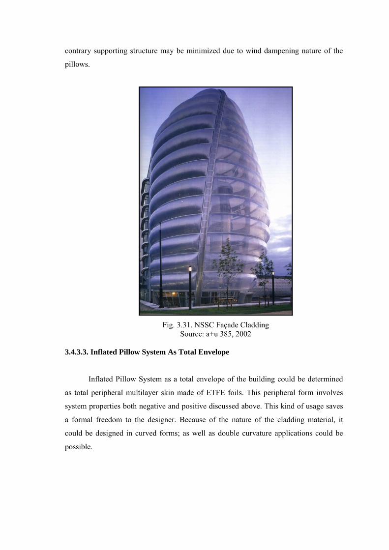
contrary supporting structure may be minimized due to wind dampening nature of the
pillows.
Fig. 3.31. NSSC Façade Cladding Source: a+u 385, 2002
3.4.3.3. Inflated Pillow System As Total Envelope
Inflated Pillow System as a total envelope of the building could be determined
as total peripheral multilayer skin made of ETFE foils. This peripheral form involves
system properties both negative and positive discussed above. This kind of usage saves
a formal freedom to the designer. Because of the nature of the cladding material, it
could be designed in curved forms; as well as double curvature applications could be
possible.

Fig. 3.34. Ozone Laboratory Source: www.lab42.architecture.uni-siegen.de
The President of Birdair Inc., L. James Newman Jr., is also enthusiastic about
ETFE foils. He points to their low cost, their translucency, and their color, which makes
interesting architectural applications possible. (Robbin, 1996)
All foil cushions are thermal insulators, especially when formed into double
cushions with three layers of foil. The seams, heat-welded to make them airtight, are
clamped into frames made of aluminium extrusions. (Robbin, 1996)
Buro Happold Consulting Engineers has developed two types of frame supports:
a rigid frame like a replacement window, and a cable-strengthened flexible frame that
allows the cushions to move under wind load and thermal expansion-in effect, a faceted
tension membrane. In areas where snow loads are heavy, thin stainless steel wires can
support the foil panels, which are limited in width to 3.6 meters but can be more than 15
meters in length. ETFE foils lose strength at 60 degrees centigrade (140 degrees
Fahrenheit), hence would probably not be useful in extremely hot climates. (Robbin,
1996)
Hampshire Tennis and Health Club is a flexible covering 6.000 square meters in
size for ten indoor tennis courts with panels 3 by 18 meters. The cable net is hung from
the poles and anchored into the ground. The clamping extrusions have been designed
for the full range of movement anticipated. (Robbin, 1996)
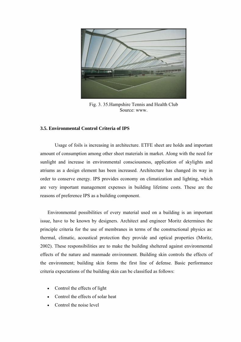
Fig. 3. 35.Hampshire Tennis and Health Club Source: www.
3.5. Environmental Control Criteria of IPS
Usage of foils is increasing in architecture. ETFE sheet are holds and important
amount of consumption among other sheet materials in market. Along with the need for
sunlight and increase in environmental consciousness, application of skylights and
atriums as a design element has been increased. Architecture has changed its way in
order to conserve energy. IPS provides economy on climatization and lighting, which
are very important management expenses in building lifetime costs. These are the
reasons of preference IPS as a building component.
Environmental possibilities of every material used on a building is an important
issue, have to be known by designers. Architect and engineer Moritz determines the
principle criteria for the use of membranes in terms of the constructional physics as:
thermal, climatic, acoustical protection they provide and optical properties (Moritz,
2002). These responsibilities are to make the building sheltered against environmental
effects of the nature and manmade environment. Building skin controls the effects of
the environment; building skin forms the first line of defense. Basic performance
criteria expectations of the building skin can be classified as follows:
Control the effects of light
Control the effects of solar heat
Control the noise level

Obtain security
Control the effects wind
Control the humidity level
Preference of IPS as a glass substitute depends on the advantage of structure
against other glazing systems. IPS can be used for facades as traditional glass
applications. IPS can also be used for roofs and skylight systems where glass is not
preferred especially for long spanning structures. Any material thought to be used
instead of glass should response the properties of glass and other glazing systems made
of glass. Transparency is a very important issue in architecture and it is not obtained by
most of the building materials. Among this little amount of materials, commonly thin
materials obtain limited light transmittance. On the other hand thin materials are not
capable to resist thermal transmittance. When possible, membranes are preferred for
most of the applications where the light transmission is needed.
IPS made of ETFE foils promotes architecture an alternative glazing system.
ETFE obtains the most of the properties of the system. But the pneumatic structure
saves system an outstanding insulating value which other membranes are not capable.
Besides the advantages and disadvantages that will be discussed in the next section, IPS
has a long life expectancy and already has proved its durability with worldwide
applications.
3.5.1. Light Transmittance And Vision Control
Light transmission is an important factor for IPS that is used as building skin.
ETFE foils each have a %95 light transmissions for 200m foil. Thinner foils transmit
the light in higher amounts like % 97. Therefore IPS is a good choice for atriums and
skylights to get the light especially in deep holes of the building. According to the B&O
Hightex translucency of the ETFE membranes is about 95% with in the range of 400 -
600 nm, with a scattered light at proportion of 12% and direct light at a proportion of
88%.
Besides the high light transmission rate the most important property of IPS is
hidden in the light spectrum. Therefore, light spectrum is important in terms of IPS light
control. Comparing with other materials, ETFE sheets main property is, especially the

high level of UV transmittance in the spectrum, which is between 150nm and 750nm.
Transmission of UV-A, UV-B is possible through the ETFE sheets. UV-A has a light
transmittance of 100 percent whilst UV-B has 50 percent. UV-C is not transmitted
through the film. It is not even reaches to the earth’s surface. Harmful UV-C is absorbed
by atmosphere in stratospheric ozone. UV light is vital for animal life and plant growth.
Plants need UV light for photosynthesis. But on the other side UV light has a negative
effect on bacteria growth. Therefore it is highly beneficial in order to protect from
bacterial diseases. These are the reason that IPS is preferred for greenhouses and zoos,
and also atriums where high light is needed in wide spectrum. Besides the benefits for
plants, UV-A is also beneficial for humans and animals. UV-A obtains suntan and other
biological processes for human skin.
The Growth of a plant depends on the existing spectrum of solar radiation. The
reasons are on the one hand the photosynthesis and on the other hand the antiseptic
effect regarding to the growth of damaging bacteriums. As shown in the figure 3.38, the
German word "Wirkungsgrad" means the degree of effectiveness regarding to an
antiseptic effect. This effect is a function of the transmittance of the radiation. The
degree of the effectiveness depends on the wavelength. The gradient of the function is
not linear. The best effect is located at a wavelength between approx. 150 and 350 nm.
The chart shows the connection between Transmittance (wave length) of the building
cover (foil, glass) and the prevention ( % of effect) of bacterium-growth. (Moritz, 2003)

Fig. 3.36. Average Light Transmission Data of ETFE Source: Skyspan Data Sheet, 2000
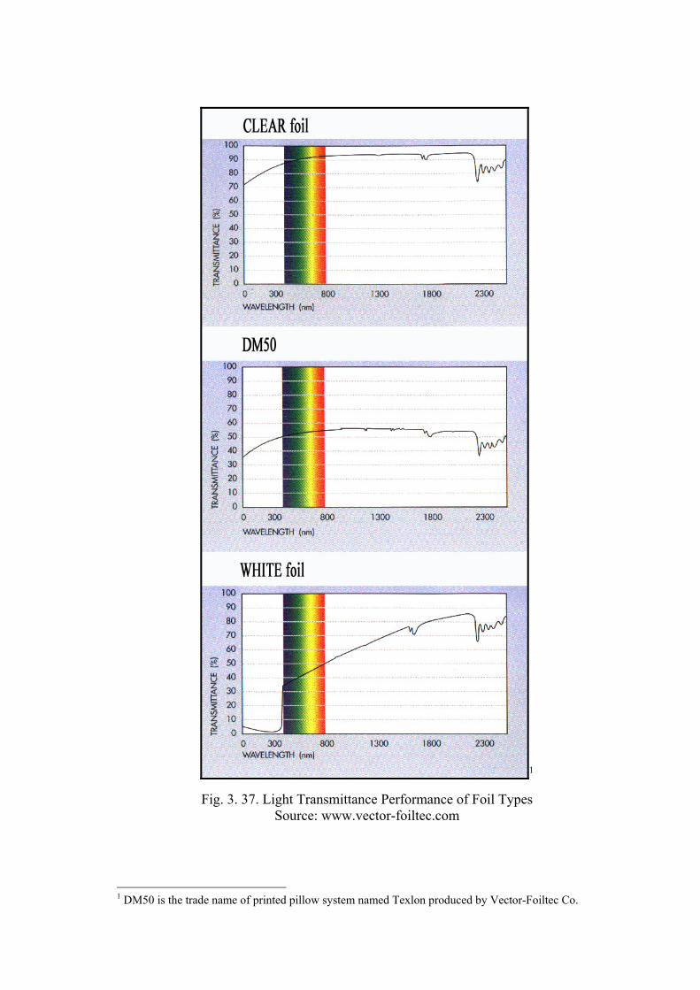
1
Fig. 3. 37. Light Transmittance Performance of Foil Types Source: www.vector-foiltec.com
1 DM50 is the trade name of printed pillow system named Texlon produced by Vector-Foiltec Co.

For a triple layer pillow structure (upper layer 200m, middle layer 100m,
inner layer 200m), the degree of light transmission for vertical incidence is τ = 0.7.
This value gives the translucency important for life of humans, animals and plants.
Fig. 3.38. Connection Between Transmittance (Wave Length) Of The Building Cover (Foil, Glass) And The Prevention (% Of Effect) Of Bacterium-Growth Source: Dr. Stefan Lehnert, Intelligent Architecture, Nov/Dec. 2000
Along with the thermal transmission ETFE is an ideal material for transmissive
control criteria. Inflatable pillows made of ETFE have a self-cleaning advantage. In
addition to that absorption rate of the foil is very low. Surface of pillows never gets dirt,
which may reduce these transmissive values of IPS.
Although it is said that %95 light transmittance is obtained with ETFE foils, the
real amount of light passing is lower in IPS. In double or triple layer applications these
amounts decreases to %78 –87. UV light values decreases in conjunction with visible
light transparency. Using white sheeting, the UV spectrum can be eliminated almost
entirely. White sheets has a total light transmittance approx. 50-55%. Skyspan, (2002)
discusses that the system with opaque foils is ideal for southern hemisphere or areas
where UV light is unwanted. Opaque foils have a visible light transmittance of 40
percent.

ETFE foils can be completely or partly printed with RAL colors. Printed foils
can be used in order to reduce light transmittance and excessive brightness of sun.
Standard productions of the ETFE foils are transparent and translucent white foil. White
layer can be used as a middle layer where that is used in Waterworks Pavilion at Earth
Center or as three layer where that is used in Hampshire Tennis and Health Club to
reduce the eyecatching sunlight. According to Skyspan, (2002) printed films are
generally consist of transparent film printed with reflective silver dots 15mm diameter
at 45mm centers. Printed systems average light transmission is 60 percent. However
average light transmission through silver areas only 30 percent.
Fig. 3.39. Waterworks Pavilion at Earth Center, Doncaster Source: Detail, 2000/6
Transparent and translucent foils can be illuminated by lighting accessories.
Therefore interesting qualities of ETFE foil lie in the relationship between their
reflections, absorption and transmission of sunlight, especially in the visible light
between 390nm and 770 nm. Foils reflect the color that is chosen. Allianz Arena is the
only example of this kind of application, which will be constructed for New Munich
Stadium designed by Herzog de Meuron.
Foils can also be dotted by color. Silver coated paints can increase reflectance
rate of the pillow in order to limit heat gain. These printed pillows could be used in
terms of intelligence. Negative and positive printed sheets are used in outer and middle
layers. Inner layer does not have to be printed. It can be either transparent either
completely printed. This system needs one more pneumatic valve to change the pressure

level inside the pillow. This is used in triple layer system. Middle layer, which is
commonly stress free in standard triple layer applications, does not have any pressure
balancing holes in variable shading system. So that two separated cavity can be
pressurized not equally. When needed middle layer moves up and blocks the light
passing through the outer layer. In these kinds of applications light transmittance rate
depends on the shape of print. This technology called as Variable Shading Method.
System obtains an intelligent opportunity for design when much light is unwanted.
Light comfort can be arranged automatically by a sensor or manually by a click of a
switch.
Furthermore, ETFE has a very low reflectance level. This saves an advantage of
glare free design. Although ETFE foils are very transparent, when inflated as a double
and triple layer pillow, visual perception is decreased naturally in parallel with the
direction of the look. The rates given are valid only for the center point of the pillow
where the sheets are almost parallel to each other.
In addition to these, from the lightweight nature of the EFTE foils, structure of
the IPS is narrow. Thus supporting structures when conceived of extruded aluminium
does impede the view at minimum. Welding opportunity of ETFE sheets promotes long
spanning without extra support that contributes visual mass unity of the building skin.
Another point to ensure best light transmittance value is providing dried air for
pillows, not to increase humidity inside. If not, humidity will block the visual
perception; moisture stick on the sheets will make the pillows translucent.
The foil can be produced with a translucent body tint. The density, colour and
number of layers can be varied. Generally it is recommended that, the use of a white
body tint to ensure internal daylight colour rendering. The translucency of the envelope
can be further varied through the construction of multi-layered cushions, with different
combinations of white, clear, and coloured foil. In addition there is matt surfaced foil,
which can further enhance the designers choices.

Foiltec has developed dynamic capabilities within IPS that can intelligently
adapt and transform their transparency, aesthetics, and thermal properties as the sun
moves across the sky, responding to specific program and climatic requirements.
Open Position
Closed Position
Fig. 3.40. Variable Shading Technology with Complex Pneumatic Systems Source: www.foiltec-vector.com
Variable shading technology has turned indoor spaces into environments that
can control or dramatize the effects of the sun. In the Festo Headquarters and the
Solarlux Showroom both in Germany the architects used variable shading system. To
achieve this dynamic shading, various positive and negative print patterns can be
developed and printed on the outer two layers of a three-layer system. The simple
change of position of the second or middle layer, either to the top or bottom of the
system, can transform the system's transparency.
The Festo Headquarters used a bold checker-board pattern to achieve a variable
transparency between 5% and 65% and in the Solarlux Showroom the designer
developed a pattern with alternating stripes - where the stripes themselves are 50%
transparent allowing the system to adjust from 45% - 85% transparent. The range of
transparency of the system is project specific and is determined by the designer's
intentions and building performance.
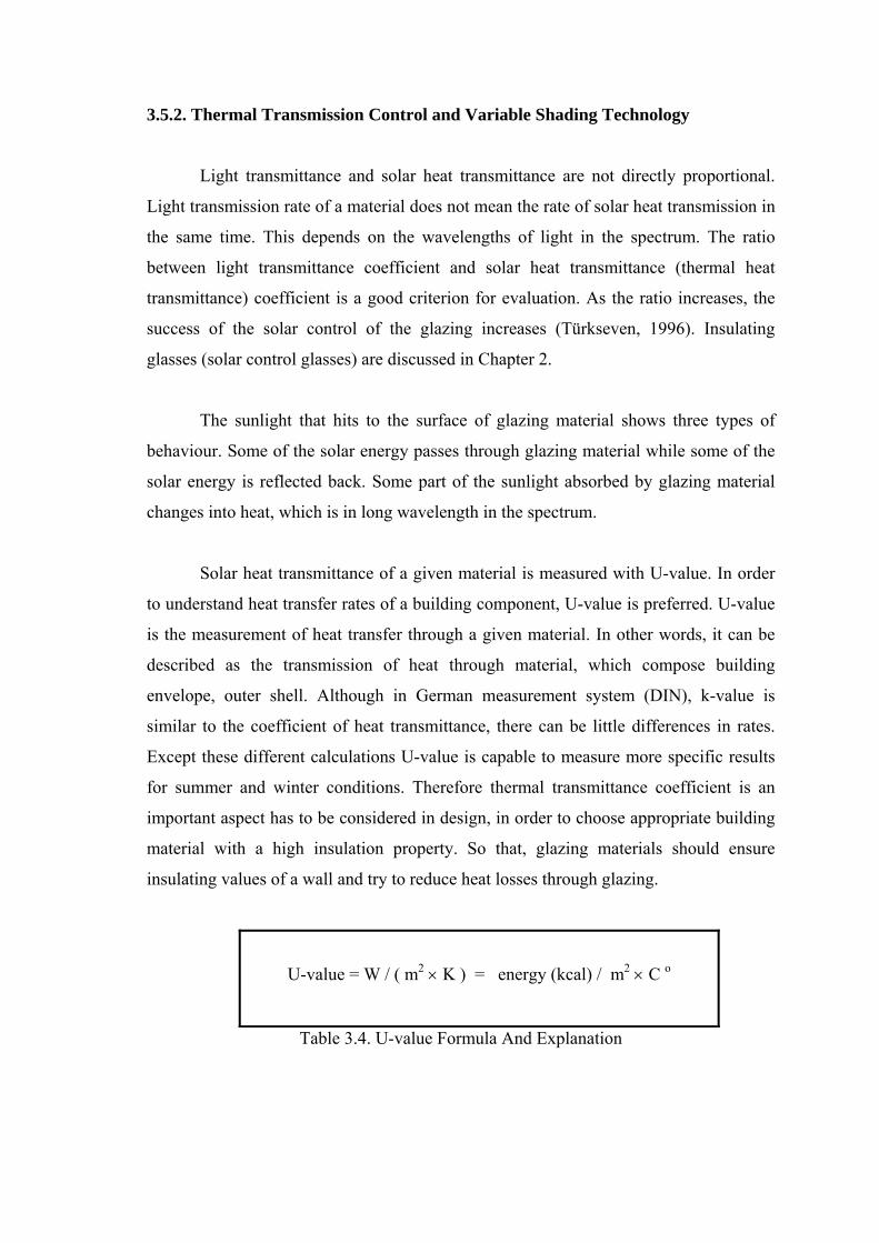
3.5.2. Thermal Transmission Control and Variable Shading Technology
Light transmittance and solar heat transmittance are not directly proportional.
Light transmission rate of a material does not mean the rate of solar heat transmission in
the same time. This depends on the wavelengths of light in the spectrum. The ratio
between light transmittance coefficient and solar heat transmittance (thermal heat
transmittance) coefficient is a good criterion for evaluation. As the ratio increases, the
success of the solar control of the glazing increases (Türkseven, 1996). Insulating
glasses (solar control glasses) are discussed in Chapter 2.
The sunlight that hits to the surface of glazing material shows three types of
behaviour. Some of the solar energy passes through glazing material while some of the
solar energy is reflected back. Some part of the sunlight absorbed by glazing material
changes into heat, which is in long wavelength in the spectrum.
Solar heat transmittance of a given material is measured with U-value. In order
to understand heat transfer rates of a building component, U-value is preferred. U-value
is the measurement of heat transfer through a given material. In other words, it can be
described as the transmission of heat through material, which compose building
envelope, outer shell. Although in German measurement system (DIN), k-value is
similar to the coefficient of heat transmittance, there can be little differences in rates.
Except these different calculations U-value is capable to measure more specific results
for summer and winter conditions. Therefore thermal transmittance coefficient is an
important aspect has to be considered in design, in order to choose appropriate building
material with a high insulation property. So that, glazing materials should ensure
insulating values of a wall and try to reduce heat losses through glazing.
U-value = W / ( m2 K ) = energy (kcal) / m2 C o
Table 3.4. U-value Formula And Explanation

Inflatable pillows made of ETFE sheets are used in increasing numbers for
transparent and translucent building skins. They are preferred with their high insulating
values. As explained, pillows are manufactured in multilayer forms. As layers are
increased in number U-values of the building skin increases. Thus, IPS does not need
any extra coating for insulation rise. Table 3.2 below shows the coefficients of heat
transmission of ETFE sheets.
Addition to that Tanno (1997), explains that a standard three layer pillow has a
U- value of around 1.95 W / (m2K), which is considerably better than triple glazing
when used horizontally. Tanno discusses that pillows thermal performance can be
further enhanced by the addition of further layers, which can be treated with Low-E
coatings. By addition of the Low E coatings U- value can be reduced below 0.6 W /
(m2K).
Number of ETFE Layer U-value* k-value* g-value*2
Single Layer 5,1 x
between 0,05-0,85
Double Layer 3,5 2,94
Triple Layer 2,0 1,96
Four Layer 1,5 1,47
Five Layer x 1,18 *Data given are approximate rates.
Table 3.5. Coefficient of Heat Transmission of ETFE Sheets Source: B&O Hightex and www.buitink-technology.com
The solar energy passed through the pillow strikes to the objects inside,
transforms to long wave energy that causes heat. The object subjected to sunlight can be
ground as well as human. Thus, inside heat blocked by building skin increases by time.
This is also called as green house effect originated by building skins. The reason for that
is the UV and visible light that enters to the building transforms to the longwave energy
(heat), which was captured inside the building.
The common usage of IPS with double and triple layer systems have 3,5 and 2,0
W / (m2K) heat transmission coefficients which are very high in transparent glazing
2g-value: Solar Gain Factor

market. Designers should be informed by the thermal effect of the surrounding frame.
Frame construction has an important effect on U-value that should not be undervalued.
All frame structures that have direct contact with the outside environment should have
thermal breaks inside the frame structure.
System’s multi layered construction can be exploited to create climatic
envelopes that sense their environments and change their insulation and solar
transitivity as required. By printing overlapping gestalt graphics on multiple layers and
integrating the cushions with sophisticated pneumatics, the different graphics can be
moved together and apart from each other.
This enables to vary both the amount of solar gain penetrating the building and
the visual appearance of the envelope. Not only can this phenomenon be exploited to
control the amount of solar transmission through the envelope but it can also be used to
vary the number of air chambers within a cushion, thereby changing its U value. These
unique properties enable designers to create buildings that are energy efficient, cost
effective and visually responsive to changing climatic conditions.
For instance, Hanover DSD’s variable skin building enclosing an exhibition of
re-cycling modulates the atria’s internal climate by reacting to the sun and changing its
transmission. The facade is water-cooled and the building generates an internal cyclone
as part of the visitor attraction.
Variable shading technology saves extra internal comfort depends on the user
demands. This additional technology of the ETFE pillows ensures solar penetration and
solar shading options. So that, user may change inside lighting conditions whenever
wanted. This method allows user a chance to exploit indoor as an public street or an
impressive indoor ambiance with the limited light gain.

Fig. 3.41. Variable Shading Technology Used At Patterned Roof of Festo AG Source: www.foiltec.de

Fig. 3.42. Duales System Deuschland, Hannover Expo 2000 Source: www.d
Through the use of complex system of pneumatics the gestalt graphics are
moved apart to allow natural light to penetrated the internal environment. (Vector,
2002). Whilst the perception of the pillows changes, the light and thermal transmittance
values are change in accordance with the movement of the middle layer. Both chambers
of the pillow differ from each other. As shown in the Figure 3.25, the picture on the
right demonstrates when the mid layer is virtually stick to the top layer. Therefore
graphics or pattern is no more visible.
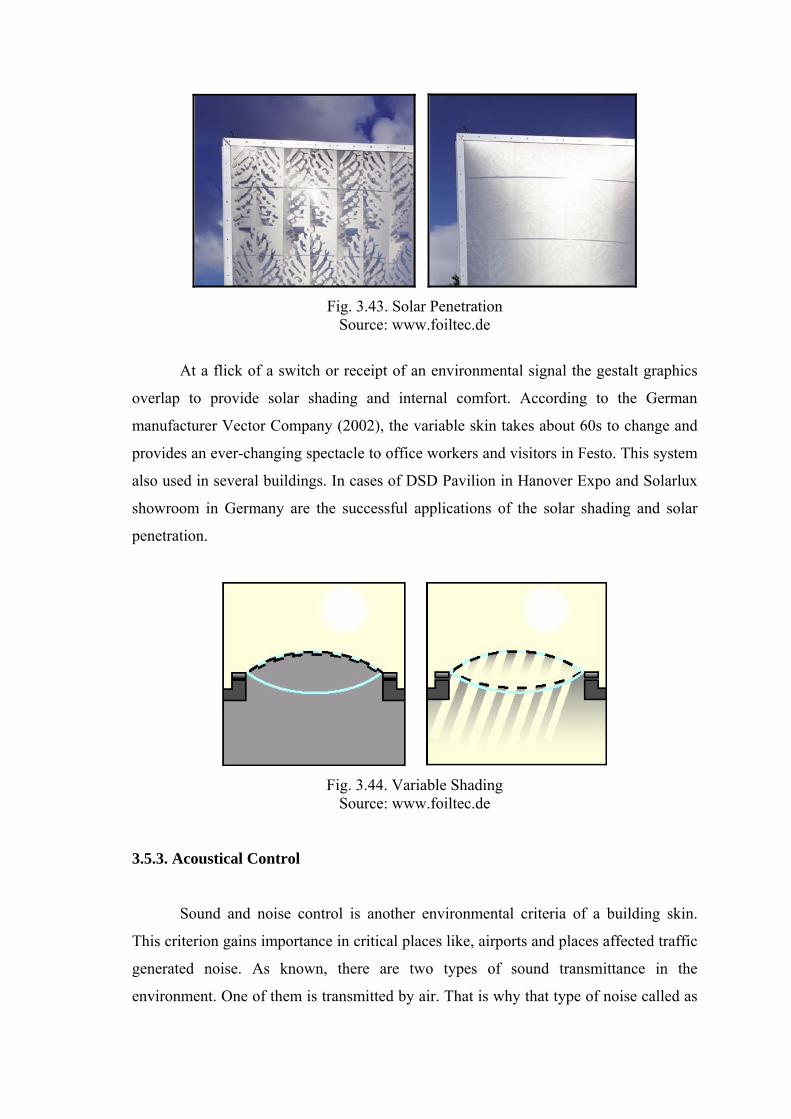
Fig. 3.43. Solar Penetration Source: www.foiltec.de
At a flick of a switch or receipt of an environmental signal the gestalt graphics
overlap to provide solar shading and internal comfort. According to the German
manufacturer Vector Company (2002), the variable skin takes about 60s to change and
provides an ever-changing spectacle to office workers and visitors in Festo. This system
also used in several buildings. In cases of DSD Pavilion in Hanover Expo and Solarlux
showroom in Germany are the successful applications of the solar shading and solar
penetration.
Fig. 3.44. Variable Shading Source: www.foiltec.de
3.5.3. Acoustical Control
Sound and noise control is another environmental criteria of a building skin.
This criterion gains importance in critical places like, airports and places affected traffic
generated noise. As known, there are two types of sound transmittance in the
environment. One of them is transmitted by air. That is why that type of noise called as

air noise. The other sound transmission type is structure borne noise. Structure born
noise is transmitted by building components such as walls and slabs. That is mostly
generated by hitting those components of the building. Construction materials have
various sound transmittance values and behaviours. Surface qualities and density have
also effect acoustical control. Besides that, internal design quality of a space is
important in terms of a correct acoustic.
Most of the membrane systems have very low sound insulation and absorption
as most of the thin construction materials. ETFE foil has a sound reduction index of
10dB, which is considerably low. Robinson-Gayle et. al. (2001) determines it as
virtually non-existent when it comes to sound control. According to Robinson-Gayle
they transmit practically all sound with a Rw (dB) of 8. Sound of rainfall and strong
wind can be heard inside. Designers should be aware of the sound performance of the
pillows in order to take precautions.
Commonly ETFE pillows have a mass of less than 1kg/m2 (three-layer), which is
light in comparison to other membranes. Therefore IPS is not capable to reduce the
externally generated sound level. But this saves another opportunity to the designer. As
the cladding does take the external sound in, it also transmits the internal generated
noise back to the outdoor. ETFE is an acoustically soft material. As in other transparent
other transparent glazing, IPS made of ETFE does not reflect the noise back. This
means lower reverberant times and a more comfortable indoor environment.
IPS made of ETFE is an ideal system for places covered with spherical domes
and other structures that have focusing effect of hard acoustic cladding. Otherwise that
acoustically hard material can disturb the internal comfort by making the speech
unintelligible. Although ETFE sheets sound reduction index is very low that may be an
opportunity for designers. When used appropriately, that may be useful for atriums,
circulation halls of shopping centres and similar places that people idle and spend time
due to the increased comfort level. That option may reduce expenses for sound dampers
against internal sound level and/or reverberation times.

The taut skin of the outer surface can create significant noise under these
conditions. Noise levels of up to 85 dB can be sustained under heavy rain. For a light
drizzle or rain, a reduction of approximately 30dB may be achieved (Skyspan, 2002).
IPS can be fitted over noise sensitive areas such as libraries and offices by fitting
rain suppressers designed to reduce rain and hail generated noise. Additionally spaces
that tend to be quiet also require acoustic insulation to prevent noise that ingress into the
space. As in case of Orange Company office building, circular pillow system adapted to
the roof structure as light wells, which are also designed to reduce internal noise level
by letting the noise out through the circular wells. On the other hand decorative sound
dampers are used as rain suppressors.
Fig. 3.45. Orange Company Light And Sound Wells And Rain Sound Suppressors
Source.www.foiltec.de
According to Morris (2000), who is the manager of Vector Foiltec Company
describes the acoustical improvements on IPS structures. The company is recently
working on jelly sound dampers for a better sound reduction index.

Lacon House in figure 3.28 and Adastral House’s lightweight roofs absorb
internally generated noise reflected from the glass and stone cladding thus improving
room acoustics. (Vector, 2002) In the atrium footfall and speech is not reflected around
so the internal space can be very quiet, but on the other hand rain is easily audible.
Fig. 3.46. Lacon House Atrium Source: www.vector-foiltec.com
3.5.4. Safety and Security Control
Building skin is the envelope that provides safety and a security line for
structures. Building skin separates indoor and outdoor environments protect against
wind, rain, snow, heat and cold shortly all environmental possibilities. Besides, building
skin should protect the building against fire, robbery and unauthorized entrances.
Therefore robustness is important in terms of safety. Building skin should have
appropriate strength in order to keep safe users. Building skin should also be airtight
and watertight. Building skin can be formed in a monolithic way or it can also be a
system assembled with more than one material. In both case, material properties are
gaining much importance for security reasons in building regulations and local
legislations.
Among other fluoropolymer EFTE foil has a very high tensile strength,
elongation (machine and transversal) and tear resistance. These high mechanical
properties make the foil an ideal construction material. ETFE foil is an almost isotropic
film, which shows the same elongation quality in both directions.

ETFE foil has a high elongation property. According to Foiltec Co. Elongation
at break is 150-200% that is tested with ASTM D 1708. ASTM D-882 tests are resulted
between 45-650%. Buitink-Technology Co. realizes similar elongation rupture tests at
23 oC and 160 oC resulted between 150-200% maximum elongation. According to the
test results “Instrom at 100mm/min” elongation at break is 300-400% (Vector-Foiltec).
Inspections on ETFE foil made by Koch Membrane Co. shows that tensile
strength of the sheet are almost similar in both directions. According to Koch, tensile
strength in machine direction is between 51 and 58 N/mm2 while in transverse direction
is between 53-54 N/mm2.
Tear strength of the foil is another important property can be exploited in pillow
structures. Building skin is not only affected by climatic conditions but also affected by
living creatures including human. Skyspan (2002) categorizes the damage into three
types; Human, Environmental and Animal. Therefore robustness is also an expectation
from IPS. Nature of the foil used in IPS is a soft material, and can be damaged by
vandalism. Human damage can be avoided by limiting the amount of access possible to
the area. Direct projectile attacks and strikes with pointed materials and sharp objects
may destruct the area subjected. Allianz Arena Football Stadium will be the largest
structure in Germany with an estimated ETFE membrane area of 65.000m2 (Moritz,
2002). Flying sticks and similar objects are the reasons of environmental damage whose
probability is relatively quite low. Any sharp objects need to hit almost exactly normal
to the surface of the foil to cause rupture. Animal damage is a common form of damage.
Birds cannot perch ETFE. This type of the damage can be eliminated by stringing
fishing line along the length of the perimeter clamp mechanism, which limits the animal
access possibilities (Skyspan, 2002).
In case of a small damage in the pillows can be eliminated with self-adhesive
ETFE stickers. But large holes that need intensive welding can be re-assembled in
production halls. According to the test results of DIN 53515 at 23oC, tear strength of the
foil is 180 N/mm, which means small holes will not propagate (Foiltec, 2002). On the
contrary, common test method for membranes DIN 53 363 gives tear strength between
400-500 N/mm (Skyspan, 2002).
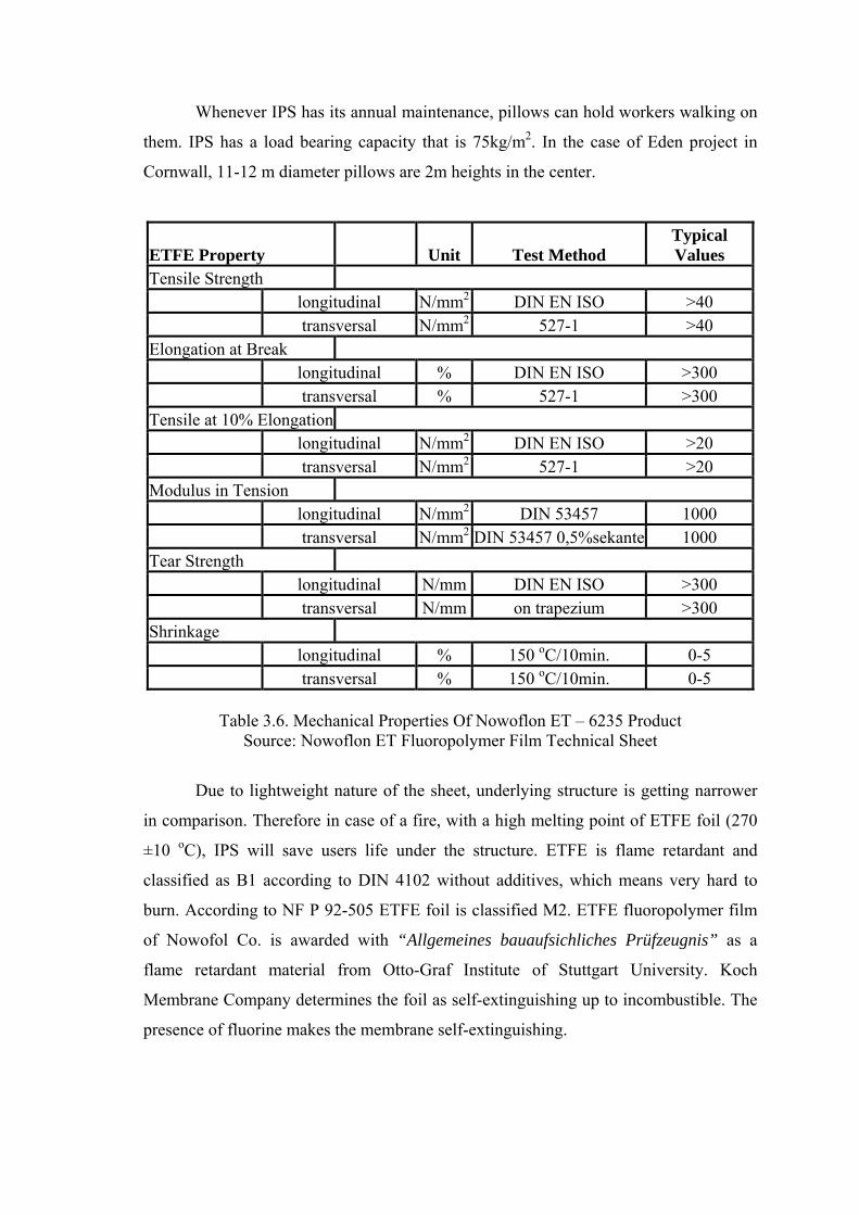
Whenever IPS has its annual maintenance, pillows can hold workers walking on
them. IPS has a load bearing capacity that is 75kg/m2. In the case of Eden project in
Cornwall, 11-12 m diameter pillows are 2m heights in the center.
ETFE Property Unit Test Method Typical Values
Tensile Strength longitudinal N/mm2 DIN EN ISO >40 transversal N/mm2 527-1 >40 Elongation at Break longitudinal % DIN EN ISO >300 transversal % 527-1 >300 Tensile at 10% Elongation longitudinal N/mm2 DIN EN ISO >20 transversal N/mm2 527-1 >20 Modulus in Tension longitudinal N/mm2 DIN 53457 1000 transversal N/mm2 DIN 53457 0,5%sekante 1000 Tear Strength longitudinal N/mm DIN EN ISO >300 transversal N/mm on trapezium >300 Shrinkage longitudinal % 150 oC/10min. 0-5 transversal % 150 oC/10min. 0-5
Table 3.6. Mechanical Properties Of Nowoflon ET – 6235 Product
Source: Nowoflon ET Fluoropolymer Film Technical Sheet
Due to lightweight nature of the sheet, underlying structure is getting narrower
in comparison. Therefore in case of a fire, with a high melting point of ETFE foil (270
±10 oC), IPS will save users life under the structure. ETFE is flame retardant and
classified as B1 according to DIN 4102 without additives, which means very hard to
burn. According to NF P 92-505 ETFE foil is classified M2. ETFE fluoropolymer film
of Nowofol Co. is awarded with “Allgemeines bauaufsichliches Prüfzeugnis” as a
flame retardant material from Otto-Graf Institute of Stuttgart University. Koch
Membrane Company determines the foil as self-extinguishing up to incombustible. The
presence of fluorine makes the membrane self-extinguishing.

ETFE Property Test Method Typical Value
Flame Retardance UL 94 V-0
DIN 4120 B1* * Measured on 200m film
Table 3.7. Flame Retardance Properties Of Nowoflon ET – 6235 Product Source: Nowoflon ET Fluoropolymer Film Technical Sheet
Maximum permanent service temperature of the Nowoflon ET and Hostaflon
ET are +150 oC. Foils are in service for a short time (6-8 hours) at 230 oC. In Addition
to that, in case of a fire event, the flame demolishes the thin foil and IPS lets the heat
and plume away, which contains dangerous gases. System saves time to the people to
run away before the whole structure collapse. Total collapse of the structure is
eventually delayed due to the heat decreased inside the structure. This self-venting
nature of the system prevents flashpoint, where the air temperature inside causes
spontaneous combustion any flammable materials (Skyspan, 2002). Whenever the space
designed as a high ceiling or as the flame cannot reach to the pillow structure, optional
sensors may detect the fire and open the ventilation windows for emergency. Therefore
it is suitable to design IPS including ventilation holes. Those holes may be used for
exhaust of smoke and fresh air ventilation.
ETFE Property Test Method Typical Value
Melting Range DSC 16 oK/min 275 oC ±10
Table 3.8. Melting Range Of ETFE Foil Source: www.buitink-technology.com
Under fire conditions any hot gases impinging on the cushion/s at a temperature
above approx. 200°C will soften the foil. As the foil is under strain from inflation, the
foil will fail and shrink back from the plume effectively venting the fire to atmosphere.
ETFE sheets produce toxic fumes under fire. According to Skyspan Co. by products are
Carbon Monoxide (CO) and Hydrogen Fluoride (HF). However, as the ETFE foils have
a very low mass-volume ratio, these toxic fumes are usually in substantial.
In case of a collapse in the pillow structure lightweight and narrow structure
cause less damage, which may be a life saving option for dwellers. The plastic range

cannot be exploited in construction, but it results in a benign behaviour in the material
in terms of safety. In other words, failure does not occur suddenly, but only after
significant increase in loading. (Moritz, 2002) As mentioned before, EFTE foil has a
melting temperature of 270 oC (Nowofol, 2002). But foil does not produce hot drops
(non burning drip), which is very important for building safety regulations.
Although IPS has a lightweight and soft nature among other glazing types, it can
resist strong winds. The stiffness of the foils is maintained by the internal air pressure of
the foil and the shape of the pillows. The pillow s may be stiffer by increasing the
internal air pressure. If required, an air pressure sensor may be fitted which
automatically increases the air pressure inside the foils to control the excessive
deformations in the system. Nansei Yacht Club in Japan has a typhoon resistant glazing
that is able to withstand 200mph winds. According to Foiltec Company IPS can resist a
wind suction load of 220kg/m2 (45lb/ft2) and a snow load of 300kg/m2 (65lb/ft2). In
some cases extra stainless steel or nickel wire netting can be useful to reinforce the
system. Therefore, designer should be aware of annual wind measurements in the
design process. Wind tunnel tests are important in this manner. Besides IPS is hail
resistant. According to the Foiltec pillow structures are resistant to hail attack proved by
SIA 280.
In case of an earthquake or a structural movement pillows can absorb some the
deformation, buckling nature of the pillows saves people under the structure from
falling parts of any broken glazing.
Finally the ETFE foil is highly electrically insulating, so that the material is
frequently used for industrial applications (Buitink-Technology). Thus, it is commonly
preferred for insulating wires, cables with the materials high electrical characteristics
(www.ersinger.com).
3.5.5. Humidity Control
The reason of the condensation on the surface of the glazing depends on the
temperature differences of glazing surfaces and the moisture level. Constant flow of air
or a wind commonly prevents the existence of humidity that may happen on the surface
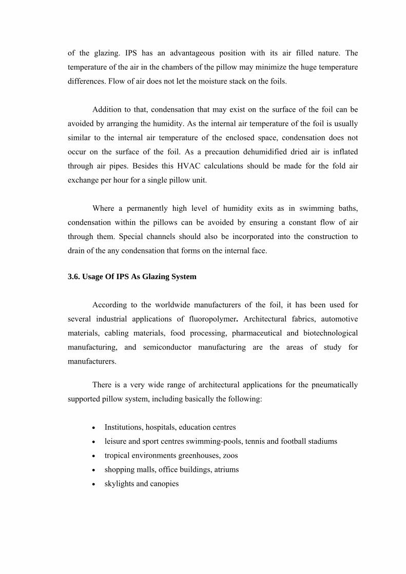
of the glazing. IPS has an advantageous position with its air filled nature. The
temperature of the air in the chambers of the pillow may minimize the huge temperature
differences. Flow of air does not let the moisture stack on the foils.
Addition to that, condensation that may exist on the surface of the foil can be
avoided by arranging the humidity. As the internal air temperature of the foil is usually
similar to the internal air temperature of the enclosed space, condensation does not
occur on the surface of the foil. As a precaution dehumidified dried air is inflated
through air pipes. Besides this HVAC calculations should be made for the fold air
exchange per hour for a single pillow unit.
Where a permanently high level of humidity exits as in swimming baths,
condensation within the pillows can be avoided by ensuring a constant flow of air
through them. Special channels should also be incorporated into the construction to
drain of the any condensation that forms on the internal face.
3.6. Usage Of IPS As Glazing System
According to the worldwide manufacturers of the foil, it has been used for
several industrial applications of fluoropolymer. Architectural fabrics, automotive
materials, cabling materials, food processing, pharmaceutical and biotechnological
manufacturing, and semiconductor manufacturing are the areas of study for
manufacturers.
There is a very wide range of architectural applications for the pneumatically
supported pillow system, including basically the following:
Institutions, hospitals, education centres
leisure and sport centres swimming-pools, tennis and football stadiums
tropical environments greenhouses, zoos
shopping malls, office buildings, atriums
skylights and canopies
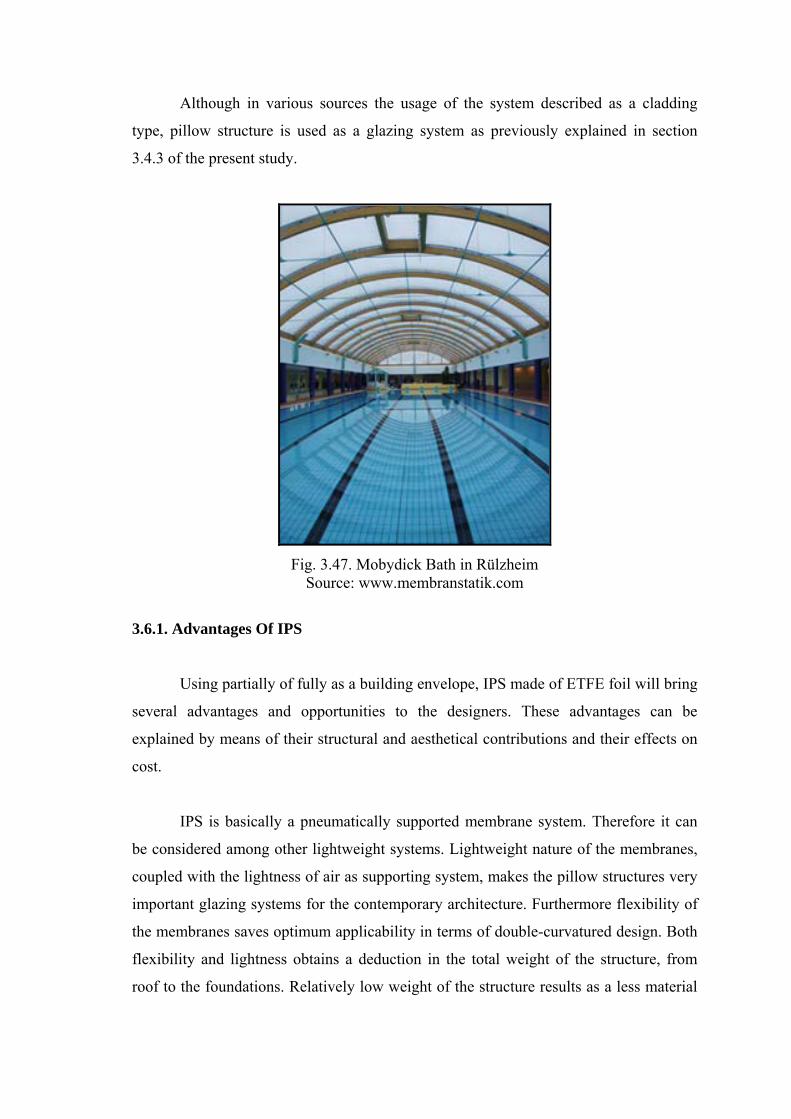
Although in various sources the usage of the system described as a cladding
type, pillow structure is used as a glazing system as previously explained in section
3.4.3 of the present study.
Fig. 3.47. Mobydick Bath in Rülzheim Source: www.membranstatik.com
3.6.1. Advantages Of IPS
Using partially of fully as a building envelope, IPS made of ETFE foil will bring
several advantages and opportunities to the designers. These advantages can be
explained by means of their structural and aesthetical contributions and their effects on
cost.
IPS is basically a pneumatically supported membrane system. Therefore it can
be considered among other lightweight systems. Lightweight nature of the membranes,
coupled with the lightness of air as supporting system, makes the pillow structures very
important glazing systems for the contemporary architecture. Furthermore flexibility of
the membranes saves optimum applicability in terms of double-curvatured design. Both
flexibility and lightness obtains a deduction in the total weight of the structure, from
roof to the foundations. Relatively low weight of the structure results as a less material
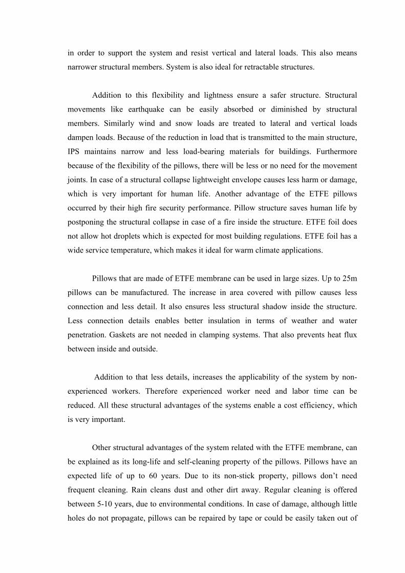
in order to support the system and resist vertical and lateral loads. This also means
narrower structural members. System is also ideal for retractable structures.
Addition to this flexibility and lightness ensure a safer structure. Structural
movements like earthquake can be easily absorbed or diminished by structural
members. Similarly wind and snow loads are treated to lateral and vertical loads
dampen loads. Because of the reduction in load that is transmitted to the main structure,
IPS maintains narrow and less load-bearing materials for buildings. Furthermore
because of the flexibility of the pillows, there will be less or no need for the movement
joints. In case of a structural collapse lightweight envelope causes less harm or damage,
which is very important for human life. Another advantage of the ETFE pillows
occurred by their high fire security performance. Pillow structure saves human life by
postponing the structural collapse in case of a fire inside the structure. ETFE foil does
not allow hot droplets which is expected for most building regulations. ETFE foil has a
wide service temperature, which makes it ideal for warm climate applications.
Pillows that are made of ETFE membrane can be used in large sizes. Up to 25m
pillows can be manufactured. The increase in area covered with pillow causes less
connection and less detail. It also ensures less structural shadow inside the structure.
Less connection details enables better insulation in terms of weather and water
penetration. Gaskets are not needed in clamping systems. That also prevents heat flux
between inside and outside.
Addition to that less details, increases the applicability of the system by non-
experienced workers. Therefore experienced worker need and labor time can be
reduced. All these structural advantages of the systems enable a cost efficiency, which
is very important.
Other structural advantages of the system related with the ETFE membrane, can
be explained as its long-life and self-cleaning property of the pillows. Pillows have an
expected life of up to 60 years. Due to its non-stick property, pillows don’t need
frequent cleaning. Rain cleans dust and other dirt away. Regular cleaning is offered
between 5-10 years, due to environmental conditions. In case of damage, although little
holes do not propagate, pillows can be repaired by tape or could be easily taken out of

the clamps to reinstall a new pillow. Thus, maintenance of the system is relatively easy,
and cost beneficial in comparison with other glazing systems. High elongation property
of the ETFE prevents people from the effects of the bomb blast.
The material is recyclable. ETFE can be melted and produced again with adding
virgin products with a very few energy. Therefore it can be reused when needed. It is
not a petrol-based product whilst not harmful to the environment. The low embodied
energy of the pillows saves and environmental cost for the human life.
The pillow structure made of ETFE foil has also advantages in terms of
environmental control criteria, as they are comprehensively explained in Chapter 3.5.
Pillow structure has a very high light transmittance. The advantage of the light
transmittance obtains an extreme deduction in electricity expenses. It is also permeable
both UV and visible light. Pillows are advantageous for gaining high UV light in terms
of photosynthesis. So that crop or harvest production increases. ETFE foil can also be
printed with color and graphics that reduces light and heat gain. Thermal properties of
the pillow systems are absolutely better than the single glazing. Due to application and
the design of the pillows thermal transmittance coefficient can be decreased. That saves
a deduction in heating and cooling expenses. Because of the nature of the membrane, it
is acoustically soft, does not reflect the internally generated noise to the back inside.
Therefore it is not needed to use expensive sound suppressors.
Most of the structural properties of the IPS and the ETFE foil cause cost
conservation in overall structure, in its life cycle. Besides that advantageous of the
system, IPS pillow saves elegant view with its unique transparency.
3.6.2. Disadvantages Of IPS
Acoustically soft nature of the foil transmits the externally generated noise. The
low thickness of the material results as a low acoustical reduction index. Traffic noise
and rain noise can be felt inside the building heavily. Therefore it could be needed
sound dampers or a second tough skin to be applied. Unintelligent use of pillows may
result as a cost consumption for additional sound suppressors.

The pillows are vulnerable by strikes on purpose. The direct attacks with a sharp
edge objects will damage the foil. Environmental affects sometimes may destruct the
pillows. Sharp sticks and tree branches may also puncture foil. Although the stickers
made of the same material, can be a way of solution, serious damages and scratches
have need to replaced by a new pillow.
Although the ETFE foil has a high melting property, membrane could be
loosening at 60oC and softening at 200oC. Therefore it not recommended for very hot
climates.
Another obstacle for the use of pillows is the feasibility. In order to get better
thermal properties (U-values) 4 and 5 layer applications may be used. But this results a
change in frames and the structural system. Profiles and the substructure obtain
structural shadow. Thus, use of 4 and 5 layer pillow structure affects total cost. In other
words, the more layers you take the more expensive it is. Addition to that the
evaluation of the system depends on the progress in the clamping and framing system.
Profiles may cause unwanted thermal bridges. To avoid heat loss through profiles
plastic based clamping stripes should be used in any case.
Although the energy can be saved by solar batteries, if electricity goes off the
system will need an extra supplier or mobile electricity generators. Therefore systems
should have a stock generator whether it can be needed or not. That is one of the
common disadvantages of the pneumatic systems.
Besides that whether the building in use or not, pillows need continuous
inflation, and so that system goes on consuming electricity which is almost 50 Watts per
hour.
3.8. Production And Manufacture of Inflatable Pillow Systems
There are number of ETFE foil producer in world. These companies produce
fluoropolymer for a wide range of industrial applications, from architectural fabrics to
semiconductor and pharmaceutical and biotechnological manufacturing. Although the

architectural membrane foil that produced is almost the same, their trade names differ
among companies.
ETFE sheeting is manufactured in three main stages – polymerization,
granulation, and extrusion - before it is tailored into its final form. According to
Robinson-Gayle et. al. (2001) ETFE is manufactured from fluorspar, hydrogen sulfate
and trichloromethane (CaF2, H2SO4 and CHCl3). The fluorspar or fluorite is the largest
natural store of fluorine; it is found all over the world and is often mined in conjunction
with limestone. These raw materials are used to make chlorodifluoromethane, a class II
substance under the Montreal treaty on ozone depleting substances that does not
contribute to global warming. This undergoes pyrolysis at 700oC to give CF2=CF2
which can be polymerized using US patent no. 4016345. The by-products of this
process are CaSO4, HCl and HF. The calcium sulfate and hydrogen fluoride are used to
make more fluorspar and the other waste products are incinerated. The polymerization
process uses water and a dispersing agent this process is carried out at approximately
125oC.
Robinson-Gayle et.al. explains that ETFE is sold in granules by manufacturers,
it is heated to its softening temperature of 170oC in the hopper of an extruder. The
extrudate is then blow moulded into large sheets 50-250m thick. Sheets can be
produced in thicknesses up to 250um and with a maximum width of 1.55m. The sheets
are heat welded together to form the multilayer pillow. The inflated pillows are
suspended in aluminium or steel frames. The finished pillows ready for installation on
site require a tenth of the energy to transport when compared with similar construction
in glass due to its much lower density.
The raw material is admitted under the Montreal Treaty and is not a
petrochemical derivative. The production process is an enclosed water based process
and does not involve the use of any solvents. In addition to that the process used to
manufacture the pillows does not require any additives to the co- polymer system and
other products are not mixed. According to Robinson-Gayle, (2001) pillows can be
directly removed from it frame and washed. It can be recycled by heating it to its
softening temperature after cleaning process. The softening temperature is low so that it
is not a very costly operation. The material is therefore recyclable and many
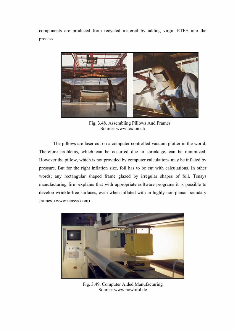
components are produced from recycled material by adding virgin ETFE into the
process.
Fig. 3.48. Assembling Pillows And Frames Source: www.texlon.ch
The pillows are laser cut on a computer controlled vacuum plotter in the world.
Therefore problems, which can be occurred due to shrinkage, can be minimized.
However the pillow, which is not provided by computer calculations may be inflated by
pressure. But for the right inflation size, foil has to be cut with calculations. In other
words; any rectangular shaped frame glazed by irregular shapes of foil. Tensys
manufacturing firm explains that with appropriate software programs it is possible to
develop wrinkle-free surfaces, even when inflated with in highly non-planar boundary
frames. (www.tensys.com)
Fig. 3.49. Computer Aided Manufacturing Source: www.nowofol.de

Pillows can either be completely prefabricated in the factory or can be clamped
into their supporting framework on site. For instance; ETFE cladding of the Eden
biomes. The lightweight structure weighs less than the air it contains. Due to techniques
used in construction site it is possible to make a scaffold free erection. Vector explains
that workers peaked at erecting 1000m2 a day during the height of the erection period,
which saved time for other applications in the construction site. On the contrary Temiz,
(2003) explains that comparing to IPS, element façade system which is the most
prefabricated system among glazing systems, allows a maximum erection almost
200m2.

Fig. 3.50. Production Hall of Tensys Company Source: www.foiltec.de
Fig.3.51.Production Hall of Texlon Company Source: www.texlon.ch

Fig. 3.52. Application Of IPS As A Skylight Source: www.buitink-technology .com
Fig. 3.53. Application Of IPS And Bird Protection String Around The Frame Source: www.buitink-technology .com

Chapter 4
APPLICATIONS OF THE INFLATABLE PILLOW SYSTEM
This chapter gives brief information about applications, which were built after
1990s’. Applications are selected around Europe. They are mostly constructed in United
Kingdom and Germany.
Previously determined contemporary applications are as below:
► Eden Project
► Hellabrunn Zoo (Lion House)
► Westminster Chelsea Hospital
► Festo AG
► National Science and Space Center
► Allianz Arena Munich Stadium

100
4.1. THE EDEN PROJECT (1995 - 2001), Cornwall, UK
Fig 4.1. The Bird-Eye Of Eden Project Source: www.edenproject.com
Client Eden Project Ltd.
Architects Nicholas Grimshaw & Partners:
Structural Engineer Anthony Hunt Associates
Steelwork Contractor Mero UK (biomes); Snashalls (visitor centre);
Pring & St Hil (biome link)
Design and Build contractors McAlpine Joint Venture
Services Engineer Arup
Cladding Consultant Arup
M+E Subcontractor Colston
Subcontractors & Suppliers ventilation air duct systems; roof and glazing to
visitor centre and biome link Allan Roofing &
Glazing Systems; glass louvres on biomes Levolux
A T, M & V, Germany; fixed glazing on biomes
Mero/Foiltec (UK Offices)
Contract Value £ 75 million size 23,000m2

101
DESIGN
The Eden project, housed in a former china quarry in Cornwall, is a giant
botanical garden. Project was the brainchild of architect Tim Smit, who is now the chief
executive of Eden. The project idea has adapted the principles of the Agenda 21, which
were established at the United Nations Conference for Environment and Development
in Rio in 1992. As explained in various sources; project conceived to "promote the
understanding and responsible management of the vital relationship between plants;
people and resources, leading towards a sustainable future for all."
The idea of this project was simple: to create a world-class tourist destination
that would tell the story of humankind's relationship with plants. Visually it had to
provide a spectacular theatre high enough to house the towering trees of the rainforests,
wide enough for the sun-baked escarpments of the Mediterranean. This construction’s
phase 1 is completed in May 2000 and it opened in March 2001. The Eden Project is the
world's largest self-supported transparent envelope, with individual panels up to 860
square feet in area. 232 panels are intelligently controlled and operable for ventilation
(www.burohappold.com).
Project architects, Nicholas Grimshaw & Partners based their design around the
geodesic dome, brainchild of the visionary architect Richard Buckminster Fuller, who is
dreamed roofing over entire cities to create new and exciting living spaces. The
geodesic principle, which involves joining together flat surfaces to form a curved shape
was the space frame specialist Mero (UK)’s idea. A geodesic line is the shortest
distance between two points on a curved surface and provides the platform for true
freeform architecture. To further strengthen the hexagons, separate diagonals connect
the node points of the layers together. According to Barker, structure of the Eden
Project is the first of its kind on this scale in the world, is called the "hex-tri-hex"
(Barker, 2001).
Barker (2001) explains that, the indoor structures were to be giant conservatories
called "biomes," which would be built on the side of the south-facing slopes of the clay
pit, providing a natural presentation arena for the plants. The structure comprises three
biomes, areas designed to represent three distinct climates found around the world. Each
biome comprises four domes, strengthened by steel arches where they intersect. The

102
shape provides maximum size and strength, using minimum steel and hugging the
contours of the clay pit's varying contours (Barker, 2001).
The domes of the Eden Project are the largest geodesic domes built yet, reaching
60m in height in places and spanning enough land to house 29 football pitches. They are
made of lightweight galvanised steel tubing of varying sizes, created and cut by a
computer Stretching over 26,000m2, the project comprises of eight geodesic domes
forming two biomes for trees and plants (www.arup.com). There is also an outdoor
biome, a visitor centre, an outdoor amphitheatre and an access road. The visitor center is
the entrance to the complex. Inspired by the laws of nature, the structures are made up
of connecting hexagons, pentagons and triangles, forming a sphere.
The project includes two indoor environments, one for humid tropics and the
other to house a warm temperate climate, along with the extensive outdoor garden for
cool temperate plants. The Humid Tropics Biome is a multi-domed greenhouse that
recreates the natural environment of a tropical rainforest. This larger biome covers
15,590 square meters or 1.55 hectares and is 55 meters high, 100 meters wide and 200
meters long (Barker, 2001). Warm Temperate Biome is 6,540 square meters or 0.65
hectares in area, 35 meters high, 65 meters wide, and 135 meters long (Barker, 2001).
Roofless Biome is an open area with varied plant life from the temperate Cornwall area.
These biomes are accessed via a visitor centre and link structure. “The Link”, a
grass-roofed building that blends into the surrounding landscape, giving the impression
that the biomes rise out of the ground. It is basically two structures in one, providing a
corridor linking the biomes as well as an exhibition, refreshment, and toilet facilities
area. The Link is sunk into the landscape, with the dining areas fronted by a sweeping
glazed wall shaded by louver screens (Barker, 2001). Link is a low-tech building, which
was conceived as a complete contrast with the space-age biomes.
This building is even designed so that it can change over time. The ETFE
pillows are built to detach easily from the steel frame, so they can be replaced should a
more efficient material come along.

103
Fig. 4.2. Fan coils inflation equipments and ventilation blinds Source: www.eden-project.co.uk

104
According to Arup, who did the environmental engineering, Eden project places
its focus upon the environment and sustainable energy. Photovoltaic and solar power are
used to pump air into the ETFE cells and solar panels provide water to the visitor centre
(www.arup.com).
The heating of the biomes is assisted by the insulating quality of the ETFE
panels. It is also facilitated by sustainable climate control mechanisms, whereby the
heat of the sun is stored in the thermal mass of rock upon which the domes are
constructed. This regulates the daily temperature and can radiate heat during the night
(www.arup.com). Heating is provided from large fan heaters, which are supplied with
hot water by an underground heating main. The direction, strength, humidity, and
temperature of the airflow is controlled by computer software. It controls the openings
at the top and bottom of the domes. Hot air is dispersed via the top and replacement
cooler air is drawn in at the bottom (www.architectureweek.com).
FOIL PILLOWS
Williams (2002) explained that the sizes of the structural members at Eden
would have been prohibitively large to support a traditional glazing solution and
transparent plastics would have degraded and could not have supported the geometries
involved.
The Eden Project designers formed ETFE material into extremely sturdy
pillows, each made from three sheets of ETFE foil welded together along the sides, one
on top of the other, with layers of air pumped in between them. In this greenhouse
project NOWOFLON®ET-film is used to cover completely with pneumatic pillows
(www.nowofol.de). Thus, biomes covered with 2 m deep inflated pillows with
diameters of between 10 and 11 m made up of three to four layers of ETFE. Each pillow
is attached to a web of interlocking steel tubes. Each dome actually has two web layers,
one with hexagonal and pentagonal panels and one with triangular panels. The
hexagonal and polygonal pillows of ETFE consist of three or four layers into which air
is pumped by a solar-powered heating system. Once inflated the pillows provide more
insulation than glass could. The total Eden structure uses 625 hexagons, 16 pentagons
and 190 triangles. The air layers provide increased insulation without decreasing the

105
amount of sunlight that shines through. The most important thing about these ETFE
pillows is that they are adjustable: On a colder day, they can be pumped up with more
air to provide better insulation; on a hotter day, they can be partially deflated to allow
more cooling (Harris, 2001).
Fig.4.3. Interior View Of The Eden Project Source: www.edenproject.com
Fig.4.4. Foil Pillows Of Eden Project Source: www.edenproject.com

106
STRUCTURE
After conceiving a couple of alternatives of Victorian style structures applicated
before as in Waterloo Station, Eden's designers decided not to use traditional materials
and structures in this greenhouse project. Geodesic dome structure is the best solution to
meet the contours of the site without so much afford and change in the topography.
Mero (UK), Nicholas Grimshaw and Partners, and structural engineer Anthony Hunt
Associates worked together to develop these series of intersecting domes. They realized
that conventional cladding material; glass was too heavy, inflexible, and dangerous for
this application (Barker, 2001). The hexagonal primary structure, designed by
Grimshaw and Hunt, consists of a tubular steel space frame connected by means of
standard node elements. Other than the nodes, there is an inner net based on a triangular
and hexagonal grid. The structure is, therefore, resolved in smaller units, which reduces
the weight and thus facilitates transportation along the narrow lanes of Cornwall (Detail,
9/2000).
The inspiration for the junction was again found in the natural world: Whalley
refers to the way in which dragonflies' wings - lightweight skin composed of a
hexagonal cell structure - are connected to the body. The decision to adopt a more
freeform structure made it possible to keep a pace of the changing state of the pit: if the
sides of the quarry moved, the domes could simply be reduced or increased in size.
Whalley says; “The hexagon appears again and again in nature. Think of flies' eyes or
honeycomb. It is the most efficient shape, in that it minimises the tube lengths in
comparison with the surface area” (Allen, 2001).
As in case of Eden Project, designing these sort of domes, which should follow
the contours of the site, is a geometrically hard exercise. Eden's designers describe the
domes as giant bubbles that can be set down just about anywhere. One advantage of this
geodesic dome shape is that it adapts easily to most ground surfaces. In geodesic domes,
the loads are not transmitted to the ground as point loads via columns, but in a linear
form along the entire perimeter of the structure, thereby eliminating the need for costly
deep foundations. Only a minor remodelling of the site was necessary, since the dome
structure can dip into the uneven topography at almost any point (Detail, 9/2000).

107
Fig.4.5.Ventilation Louvers Of Eden Project Source: www.edenproject.com
Fig.4.6. Foil Pillows Of Eden Project Source: www.edenproject.com

108
The steel frame of the geodesic dome is incredibly strong relative to its weight.
This weight (667 tons) is dispersed evenly throughout the entire structure so that the
dome only needs support around its base, leaving lots of room for the plants inside. The
edges of the dome rest on a sturdy foundation necklace, an underground concrete wall
around the perimeter of the structure. (Harris, 2001).
The structure was further refined by introducing an inner layer, which meant that
member sizes could be reduced from as much as 500mm in diameter to less than
200mm. At the point where two spheres of different sizes meet, the hexagons change
shape to allow members to join the steel arch trusses, which form the primary structure
linking the domes (Allen, 2001).
The structural frame of the biomes is a three-dimensional space frame in circular
hollow sections. The frame comprises an icosahedral geodesic outer layer with an inner
layer of hexagons/pentagons and triangles. The centre points of the outer layer define
the hexagons/pentagons of the inner layer, which form triangles under the outer frame
nodes. Separation of the two layers is by circular hollow sections connecting the nodes
of the hexagons/pentagons (Allen, 2001).
The frame spans from front to back on to anchored reinforced concrete strip
foundations. Structural stability for each of the biomes is afforded by the shell action of
the combined intersecting domes, anchored to the foundations by pinned connections.
Around the perimeter of the spheres the inner structural members are brought out to
meet the outer members, forming pinned connections to the foundations. The roof
structure is designed to accommodate the forces and movement due to temperature
effects by 'breathing' alone. Because of the nature of the pillow system there were no
need for the movement joints within the roof structure (Allen, 2001).
The biomes were erected with a combination of cranes (static and mobile) and
scaffolding. The scaffolding made the Guinness Book of Records. At 58.5 meters, it
was the highest freestanding structure in the world. The scaffolding also broke the
record for the largest volume in one structure, at 195,600 cubic meters. The ETFE
pillows made and fitted by the German company Foiltec, were installed by construction
workers using mountain-climbing techniques (Barker, 2001).

109
Fig.4.7. Construction Phase Of Eden Project (1) Source: www.edenproject.com
Fig.4.8. Construction Phase Of Eden Project (2) Source: www.edenproject.com

110
4.2. HELLABRUNN ZOO (JUNGLE HOUSE), Munich, Germany
Fig. 4.9. The External View Of Hellabrunn Zoo www.pfeifer.de
Client MunchenerTierpark Hellabrunn AG
Architects
General :Buro Herbert Kochta Architekt BDA, project architect
E.Lehner
Landscape architect : Büro Teutsch + Partner
Cable net structure : Büro IPL-Ingenleurplanung Leichtbau
Structural engineering
Cable net and membrane: Büro IPL-lngenieurplanung Leichtbau (design);
KOCH HighTex GmbH (general contractor); Schlaich, Bergermann + Partner
(in cooperation with the contractor)
Reinforced concrete structure and substructure: lngenieurburo Dieter
Herrschmann
Specialist consultants
HVAC : lngenieurburo Bergbauer
Thermal/moisture insulation : Prof. Schaupp, GrUnwald
Term planning, site supervision : lngenieurbUro Zinner & Sohn
Installations : lngenieurbüro Bergbauer
Electrics planning : lngenieurbüro IBE RoIf Günther
Contractors
General contractor & roof : KOIT HighJex GmbH
Facade : Glasbau Seele

111
DESIGN
The Hellabrunn Zoo, which is situated in Munich Zoo at the foot of the
Harlaching hill in a landscape protection zone, is completed in 1995. As a novel zoo
concept, visitors separated from animals only by glass panes. So that, animals can move
around freely in natural setting. A little stream with waterfall, walk-on 'hills' and sump-
tuous tropical and subtropical vegetation create the impression of a visit to the jungle.
This building has an octagonal plan, which is symmetrical about one axis and
defined by curved edge cables. The covered plan area of this building is 1140 m2. Two
visitors entrances are situated on the northwest side and animal boxes for large
carnivores are arranged along the facades, some of them having access through the
facade into open-air enclosures. On the longitudinal side facing the entrances lies an
artificial planted hill. There are number of bird boxes and other ancillary rooms are
located together with the delivery entrance under this hill. In the middle part, on both
sides of the mast foundations, there is a plant area without underlying ground slab.
STRUCTURE
For the natural growth of the plants and their protection from parasites and
diseases maximum levels of UV-light are necessary. In addition to that, the minimum
temperature may not drop below 12 0C. These considerations require investigating of
wide-span structures and transparent cladding systems in design stage of this building.
At the end, the solution of a cable-net roof emerged with a cladding of pneumatic foil
pillows.
In the Jungle House, two 17-m high masts carry the pre-stressed net structure,
which are made from high-grade steel cables with a mesh width of 2 x 2 m. This two
cable-braced tubular steel masts; a straight compression tube is stabilised through a
three-chord tie bracing of round steel bars with star shaped spreaders. These spreaders
made from short compression struts and arranged along the mast length. While at the
masthead, the ridge and eye cables are connected, which at the same time laterally
support the mast tip; at the base, the masts are pin-supported on the reinforced concrete
substructure. The edge masts consist of simple tubular steel columns. Briefly, the

112
structure is composed of double radial cables ( 18 mm) and single hoop cables (16
mm); at the top it is supported by four ridge cables (32 mm), held at the edge by edge
cables ( 36 mm) and anchored at its eight corner points by masts, guy cables (36 mm)
and injection anchors.
This structural system and foil pillows are resistant to external loads such as
snow and wind loads. Snow loads are carried by the internal pressure into the lower foil
of the pneumatic pillows and into the radial cables of the net, which introduces its load
mainly into the ridge cables connecting the masts. The statutory snow loads to DIN
1055 were fully allowed for in the structural calculations. Wind loads are carried by ring
and radial cables into edge cables and substructure. The net cables are joined through
movable high-grade steel cable clamps, onto which the edge clamping arrangement of
the pillows are fastened. The pillows have been developed into cutting patterns along
edge and surface seams and are connected via a boltrope edge and by special
aluminium-edge profiles to the cross clamps of the cable net and to the edge cable
clamps. The cable clamps of radial and ring cables are connected with a central bolt and
are free to rotate, so that the mesh angles can adjust freely to adapt to the three-
dimensionally curved cable-net surface.
The net edges are 3.5 m above the ground; there the net cables are equipped with
a swaged closed cable fitting which is pin-joined through a flexible one-bolt connection
with two forked connecting elements, which in turn are fastened to a two-piece, circular
edge cable clamp. At the net corners the edge cables are connected via fork fittings
directly to the head plates of the edge masts. The four ridge cables running from one
masthead to the other are joined at the junctions with the radial net cables through a
welded cable clamp. The net cables are connected to its lower plate stiffener by a
swaged fork fitting and a flexible one-bolt connection. Under the ridge cable and
suspended from it run a cable tray and the supply pipes for the pneumatic pillows. The
ridge is closed on top through a grating, serving as a service walkway, and by a double-
layer of ETFE-foil above it connected with the membrane pillows along their edge. This
unorthodox solution allows walking on the ridge and at the same time provides a
transparent and thermally insulated ridge covering. The ridge cables are continued on
the other side of the mast down to edge guys, forming eye shaped openings, which are

113
closed with mechanically operated ventilation louvers.
Fig. 4.10. Hellabrun Zoo Interior (1) Source: Schock, 1997
Fig. 4.11. Hellabrun Zoo Interior (2) Source: Schock, 1997

114
CONSTRUCTION
For the installation of the roof structure scaffolding was erected in the interior.
After positioning of the masts, the cable net was assembled on the scaffolding from
single cables connected at the nodes by cable clamps and raised gradually. However, the
edge areas inaccessible from the scaffold had to be worked from the net. The net was
pre-stressed from ridge and edge cables to 8 anchor points. The prefabricated pillows
were fixed first along one side of the High-Tex cushion profile, rolled out sideways,
tensioned and finally fixed on the other cushion side. The entire construction period
totalled 3 years.
FOIL PILLOWS
The pneumatic foil cushion system is most suitable system for this building. An
alternative cladding system exploring overlapping small polycarbonate panels had to be
excluded because of its large air permeability and the resulting unsatisfactory thermal
insulation.
The foil pillows are composed of two fluoropolymer foils (t = 0.2 mm). This
roof allows photosynthesis to take place and temperature to be controlled. The
translucency of the roof structure is important for plant growth totals approx. 90%.
Besides that, the translucency of the foil itself in the UV ranges amounts to 96%. The
64 wedge-shaped pillows (max. b = 2.5 m, max. I = 18 m) are filled individually with
dried and purified outside air via separate, flexible and closable cushion feeds through a
pressure pipe running along under the ridge, which helps to prevent condensation and to
preserve the translucency of the pillows.
The inflation pressure varies according to the external loading, wind and snow,
and is controlled by a computer system, which can compensate minor damage of the
membrane through a pressure increase. The pressure normally amounts to 250 pa and
can be increased to 350 pa if required. For the inflation of the pillows altogether 4 fan
units are provided, with one main and one reserve blower. The latter serve to ensure the
safe working of the system even in case of breakdown of a main blower, and also serve
115
to increase the air volume in case of damage to the membrane. The air supply is
controlled centrally using an anemometer located at one of the masts.
The wind and rain-proof connection of the foil cladding with the heated steel and
glass facade must be able to tolerate large deformations of the roof, e.g. under snow
load. The connection is made through curved tube pillows, which are fastened to the
upper edge of the facade, held in position with cables and pressed against the roof
pillows by their inflation pressure. In addition to the air supply controlling the pressure,
relief valves are installed, which open at a sudden pressure increase under load and thus
allow a fast pressure adjustment. A further internal sealing tube, running parallel to the
edge belly cables provides an almost perfect air seal and at the same time prevents the
escape of small tropical birds.
The aluminium edge sections, which hold the transparent foil pillows at the
edge, proceed from the ridge radically down to the lower net edge. These High-Tex-
aluminium extrusions, which are consisting of three principal aluminium extrusions and
an extruded cover strip section, are bolted directly onto the radial cables. The ring
cables are connected with a spacer piece to the radial cables underneath and are located
under the foil pillows, so that these can deform unhindered under load. The 'belly
cables' common in earlier cushion structures were not used here. They are, however,
used along the edge, to hold the sealing tube in place.
VENTILATION
On two sides of the masts ventilation ducts proceed to the air intake funnels
located at the mastheads. In the winter months, these air intake funnels serve as forced
ventilation and the air speed had to be kept much lower than in similar ventilation
systems. Through the funnel shape the air cross section is expanded which decreases the
air speed. According to the HVAC calculations a 10.5 - fold air exchange per hour is
sufficient for the single cell cushion roof, so that even given extreme outside
temperatures the inside temperature does not move outside the required tolerance band.
On the other hand, during the summer months, the building is ventilated by natural
stack effect through two large net openings. They consist of lens-shaped areas cut into
the membrane and closed by acrylic glass louvres individually supported by stainless

116
steel brackets sealed to each other. They can be moved continuously and have their
aperture angles regulated electronically. The system can be opened so that the entire net
eye area is available as a ventilation opening.
Fig. 4.12. Detail Of Cable Net Structure Source: Schock, 1997

117
4.3. WESTMINSTER AND CHELSEA HOSPITAL ROOF, London, UK
Fig.4. 13. Westminster & Chelsea Hospital Source: www.foiltec.com
Client Northwest Thames Regional Healty Authority
Architect Sheppeard Robson Limited
Structural Engineer Buro Happold
Atrium Roof contractor Sheetfabs, Nottingham
Texlon Foil supplier Vector Foil Ltd, London
DESIGN
Glass is the usual choice for the transparent material of an atrium roof. However,
it is heavy, especially if double-glazing is needed to reduce heat losses, and a substantial
structure is needed to give a glazed roof sufficient strength and stiffness. At the heart of
the new Westminster & Chelsea Hospital is a vast barrel-vaulted atrium, 116 metres
long and 85 metres wide, with four transepts. In view of the large area to be covered it
seemed likely that recent developments in the field of lightweight structures might
present some alternatives to the traditional glazing solutions (Interaction).
It is interesting to note that the principles and logic behind this roofing system
are virtually identical to Paxton's glazed ridge-and valley system which he developed
for the Crystal Palace roof (except for the pneumatic element). But it is in the nature of
any innovation, then, as now, that it is not possible to predict at the beginning of a
project what the most suitable design will turn out to be. On this project, considerable
time and effort for design development was needed in the early stages to achieve an

118
original solution, which would finally bring substantial benefits compared with
conventional roofing systems. The risk in such an investment in resources is inversely
proportional to the level of confidence in the skills of the design team (Interaction).
Fig. 4. 14. Internal View Of Westminster & Chelsea Hospital (1) Source: www.foiltec.com
Chelsea and Westminster Hospital, is the largest hospital in England that is
serviced in July 1992. A key feature of the design is the arrangement of the main
buildings around a large central atrium. The atrium unifies and organizes the entire
complex with light and warmth, and is the largest naturally ventilated atrium in the
world (www.burohappold.com). This atrium not only creates a flexible internal space at
the heart of the building, but also greatly reduces the area of the wall cladding exposed
to weather. For this space to be successful, the roof had to be capable of allowing a high
percentage of natural light passes through into the rooms adjoining the atrium as well as
down to the ground floor. This building utilizes segments of transparent, translucent,
and operable foil panels to create a natural and cost-effective lighting and ventilation
scheme (www.vector-foiltec.com).

119
STRUCTURE
Buro Happold used a rigid frame and foil system for the RHWL's Westminster
Chelsea Hospital atrium roof, with an overall nave and crossing transepts and with short
spans of approximately 20 meters (Robbin, 1996).
The atrium space is 116 m long with an aisle 18 m wide running the full length
with four cross transepts increasing the width to 58 m in each case. Consequently, the
roof could be arranged to span the 18 m distance across transept and aisle with addition-
al structure required only at the junction of aisle and transept. As Cook (1994) said, the
structure is designed to act as a series of three pin arches spanning across the void,
springing from a perimeter gutter beam. This beam resolves thrusts by spanning
horizontally between internal or external corners of the roof where the reaction is car-
ried in vertical bracing. The gutter is held above the general building level by means of
steel struts, allowing ventilation louvers to be installed within the perimeter frame. Aisle
arches meet transept arches along diagonal valley lines. Local horizontal thrusts at these
corners are resolved by horizontal cross struts, which connect across to diagonally
opposite corners in the perimeter gutter beam.
Fig.4. 15. Section Drawing Showing Components Of Atrium Roof Source: www.foiltec.com

120
The roof form adopted to provide structural support for the foil pillows is a
series of barrel vaults along the aisle and transepts with each barrel being terminated in
a curved end section. Taking due allowance of the size to which the foil panels can be
produced, the support structure was provided on a grid approximately 4 m X 3 m.
(Cook, et al., 1994).
The arches themselves were developed to provide integral fixing flanges for the
pillows and a simple erection technique with a minimum of complex connections on
site. Half arches were made up as frames, each of which could carry two foil panels.
Members along the side of a frame are half of a box arch member, which is bolted to the
other half member of an adjacent frame once on site. Each frame is itself stable once the
opposing frame is installed to complete the arch. Prefabrication of units such as this
reduced the problems of tolerance for the fit up of the pillow panels and reduced the
number of site connections required (Cook, et al., 1994).
The frames were designed initially on the basis of using glass reinforced poly-
ester resin (GRP). This would have provided a smooth self-coloured surface and would
avoid the need for exposed nuts and bolts if local site lay-up were permitted at joints.
GRP does not corrode and degradation could have been avoided by addition of
sufficient LV inhibitors and additional weathering resistance to the external gutter
surfaces between panels. The flexibility of GRP in comparison with steel or aluminium
was not significant as the cladding system is tolerant of movement. CRP allowed a
reasonably complex arch section to be developed incorporating flanges for fixing the
foil pillows and the air supply lines for the pillow (Cook, et al., 1994).
The very low weight offers enormous potential to achieve both lightness and
economy in the supporting structure. Both glass-reinforced plastic and aluminium alloy
were considered as materials for making the arched supporting frames, and both have
very much better strength-to-weight and stiffness-to-weight ratios than steel. Although
the aluminium alternative was finally chosen for its low maintenance needs and superior
durability, it also has a particular manufacturing advantage. Aluminium alloys can be
formed into extremely complex cross-sections by extrusion through a die. This
production technique enabled the many different functions of both the supporting frame

121
for the foil pillows and the structural ribs of the barrel vault to be achieved using just
two different extruded sections. The requirements were that the frame and ribs should:
(Interaction).
have a high section stiffness (second moment of area);
support the stainless-steel wire grid;
allow watertight fixing of the pillow foils into their frame;
house the air-supply duct needed to inflate the foil pillows;
incorporate an external gutter for rainwater;
provide drainage channels for condensation forming in the box section;
provide small drainage channels to catch condensation forming on the underside
of the pillows;
provide brackets for bolting together the various components and achieving
waterproof joints;
incorporate hooking points for internal cleaning gantries. (Interaction)
By extruding only one half of a box arch, the problem of extruding closed boxes
was avoided. Sections of extrusion were cut and welded off site to form the “figure-of-
eight" frames. Site assembly required connection to be made only around the perimeter
of each unit. Site welding was not required. The flexibility of aluminium compared with
steel was not significant in the context of a roof clad in foil. The lightness of the frames
was a considerable advantage on site, reducing required crane work (Cook, et al., 1994).
The new roofing system thus developed was not produced by taking an existing
system and improving individual parts. There was a fundamental rethink as to how to
achieve the required performance of an atrium roof. The result is a remarkably tight
integration of structure and services: no one part can be changed without affecting some
or all of the others - a singular solution for a unique set of circumstances (Interaction).
CONSTRUCTION
The roof installation proceeded according to programme and was unusually
rapid for a structure of this size. This speed allowed for an early start on installation of
internal cladding. The roof is performing up to expectations and transmits a very high
122
level of natural light into the atrium, which functions as a primary communication space
via bridges at every level, as well as a vital central forum at ground level. Whilst the
technology of using foils as roofing materials is relatively new, the problems are all
soluble by the application of engineering principles. This form of roof cladding offers
clear advantages over more conventional systems and seems destined to become
increasingly important for future construction needs (Cook, et al., 1994).
For easy construction it would also be necessary for the pillows to be pre-assem-
bled as self-contained units, which could be carried into position and fixed from the
outside. The pillows that were developed in this way are about 4 metres x 3 metres in
area and 250 mm thick at their centre. These pillows were inflated to a depth of 600
millimeters at a low pressure of 400 pascals (about 5 pound per square foot) (Robbin,
1996). They have a thermal performance and transparency similar to triple glazing but
at about one fiftieth of the weight (Interaction).
FOIL PILLOWS
This fact alone made the use of a fabric membrane roof cladding unattractive
and pointed to a glass or foil solution. Glazing of the roof would have added to the
building weight, would have required a heavy roof support structure and would have
been expensive. The use of a lightweight clear foil roof cladding system was selected as
the best option (Cook, et al., 1994).
The key to good thermal insulation in glazing is the air gap between the glass
sheets. Transparent foils of plastic can also be used to contain the air and are very much
lighter but alone, such a combination of materials has no useful structural properties.
These ideas were judged to be worth developing for this large atrium roof, especially in
view of the high insulation that might be achieved (Interaction).
ETFE foil, a material that a few years ago tended to be thought of as a cheaper,
lighter, shorter-life glass substitute made Chealse and Westminster Hospital respectable
(“Products” Architects’ Journal, 2002). Although clearly not as versatile as more
conventional fabric based materials, ETFE is highly appropriate where a support matrix

123
can be provided. Indeed these pillows also provide a thermal performance rather better
then double-glazing for approximately a quarter of the weight (Pugh and Cook, 1995).
Fig. 4.16. Internal View Of Westminster & Chelsea Hospital (2) Source: www.foiltec.com
To increase the thermal insulation it was decided to use three foils and it proved
viable to create flat pillows of different shapes by clamping the foils at their edges and
keeping them inflated by air maintained at slightly (0.5 per cent) above atmospheric
pressure (Interaction). This foil layer needed to be only 30 microns thick for being un-
stressed. Whilst the outer layer is 200 microns thick, the inner layer, which is not
stressed by external loads, is only 150 microns thick (Cook, et al., 1994).
As a security against plastic elongation, a series of light steel cables is sus-
pended beneath the bottom film layer. Under wind suction, the outer layer is more
highly stressed and its thickness was chosen to ensure that adequate safety against
plastic elongation was maintained. Under snow load, the outer layer will tend to invert
once the load exceeds the inflation pressure of 500 N/m2 (Cook, et al., 1994). However,
due to the presence of plant enclosures on the roof around the perimeter of the atrium
roof, drifting snow could produce much greater snow loads locally. As an increase in
internal pressure would require an increase in film thickness (which would be
expensive), the use of a safety net of cables was preferred and this net was suspended
beneath each panel (Cook, et al., 1994).

124
INFLATION SYSTEM
The foil panels were delivered to site set in their extruded aluminium clamping
frames. Each panel could be hand carried on site and installed by a series of bolts
around the perimeter. The air supply for inflation was provided by means of individual
pipes leading off a supply pipe running inside each arch. An inflation system is required
to maintain the pillows at a constant pressure of between 400 and 500 N/m2. This is
achieved using centrifugal fans with backward curved aerofoil blades. The
characteristics of such fans ensure a reasonably constant internal pressure over a range
of airflow rates. This helps to ensure a fairly constant air pressure even when the flow
rate increases to compensate for unplanned leaks (Cook, et al., 1994).
In the event of damage or removal of a single pillow, the air loss is constricted
by the supply pipe, which is only 20 mm diameter. The fans are capable of providing
the additional flow required to maintain a virtually constant inflation pressure in all
remaining pillows. Air is supplied by 8 inflation units around the roof. Each unit sup-
plies air to approximately 40 pillows and has one running fan and one stand-by. Each
fan has a power requirement of around 100 Watts (Cook, et al., 1994).

125
4.4. FESTO TECHNOLOGY CENTRE (Festo HQ), Stuttgart, Germany
Fig.4. 17. External View Of Festo Technology Centre Source: www.pfeifer.de
Architect Architekturburo Jaschek
Glass facade manufacturer Okalux
DESIGN
A new technology centre has been constructed at the headquarters of Festo, a
multi-national manufacturer of pneumatic equipment, in Esslingen, Germany. The Festo
Company is the world market's technology leader for pneumatic control systems and
power tools. The designer of their new headquarters, Architect Jaschek, collaborated
with their client to create a building that spole of Festo's technology-driven and
ecologically sensitive design approach. This challenge stepped beyond the typical
commercial approach to create additional space, and successfully represents Festo's
progressive strive to be the technology and ecological leader in their market
(www.burohappold.com).
The architect designed six finger-like buildings that are connected by a central
spine, which serves as the entry area for each of the fingers. Out of the five interstitial
spaces between the finger masses, three have been covered with a state-of-the-art
Foiltec System, converting them into dynamic multi-function atrium spaces. Foils

126
Fig. 4.18. Festo HQ Roof Close Up (1) Source: www.vsp.com
Fig. 4.19. Festo HQ Roof Close Up (2) Source: www.vsp.com

127
span the barrel-vault structure over varying distances between 45 feet and 70 feet. The
architect envisioned the roof to be light and transparent, and at the same time,
climatically responsive. Foiltec designed an integrated shading system intended to keep
solar gains in critical climate conditions to a minimum, enabling the atria to be
temperature-controlled without mechanical cooling systems. This pneumatically
operated roof provides variable shading, responding both to climatic conditions and to
the occupants' needs.
Fig.4. 20. Internal View Of Festo Technology Centre Source: www.pfeifer.de
STRUCTURE
Festo Headquarter has three V-shaped atria roofed with pneumatic pillow
structures and enclosed on their south sides by glass facades held in place by delicate
wire-rope cable structures. The atria act as meeting places for the company's employees,
and serve as buffer zones to provide passive solar energy gains (www.arplus.com).
The structural system, consisting of steel hollow sections and interior cables,
takes most of the suction loads from the roof and the integrated glass end-wall facade
(www.burohappold.com). The glass facades were manufactured by Okalux in

128
Marktheidenfeld, Germany. They comprise a series of glass panels, 2.4m x 2m in size,
each of which is fastened with four clamps to a cable net structure. This in turn is
rigidly connected with compression and tension rods to a secondary, curved cable net,
which takes up lateral wind loads. Inward flexing due to wind-generated stresses is
taken up by horizontal wire ropes; outward flexing due to wind-generated suction is
transmitted to the building's ground-floor slab or conducted to points beneath the roof
girders by vertical wire ropes (www.arplus.com).
Fig.4. 21. Details Of Roof Structure Source: www.pfeifer.de
FOIL PILLOWS
In the Festo Headquarters the architect used “variable shading system” in
Germany. The variable skin takes about 60 second to change and provides an ever-
changing spectacle to office workers and visitors in Festo (Vector). This technology has
turned indoor spaces into environments that can control or dramatize the effects of the
sun. This variable skin building modulates the atria’s internal climate by reacting to the
sun and changing its transmission to maintain internal climate. These 1200sqm roofs
use this chessboard gestalt pattern to modulate and change the amount of solar gain and
light penetrating the atria. To achieve this dynamic shading, a bold checkerboard pattern
used to achieve a variable transparency between 5% and 65% (www.foiltec.com). The
upper foil of the three-layer system has a positive and the middle one has negative
pattern. By changing the position of the middle layer to either the top or the bottom of
the system, the transparency and the insulating value of the roof can be adjusted
(www.burohappold.com). The range of transparency of the system is project specific
and is determined by the designer's intentions and building performance.

129
4.5. NATIONAL SPACE SCIENCE CENTRE (Rocket Tower), Leicester, UK
Fig.4. 22. External View Of NSSC (1) Source: www.skyspan.com
Architect Nicolas Grimshaw & Partners, UK
Consultants
Structural and services engineers Ove Arup & Partners
Construction team Sir Robert McAlpine Ltd
Steelwork contractors SH Structures Ltd
Project managers GardinerTheobald Management
Services
Landscape consultants Land Use Consultants
Cladding consultants Montressor Partnership
Fire engineering consultants Locke Carey Associates
Exhibition designer Haley Sharpe
DESIGN
The National Space Science Centre, a landmark Millennium Project for the East
Midlands, is a catalyst for the promotion of public interest in space science. This
building, which its height is 41 m and its size 7,200 m2, combines an exhibition venue
of international standing and a new centre of excellence for education and research

130
affiliated to the University of Leicester. The building has been designed to reflect its
proximity to the historic Abbey Pumping Station. Located on a former 'brownfield' site
on the north bank of the River Soar, it occupies the majority of the riverside frontage in
the shell of a disused storm-water tank. Its development as an amenity represents a
significant environmental improvement, both for the immediate neighbourhood and for
the city as a whole. The tower is designed both as a showcase for high-profile exhibits
and as a tangible example of the use of innovative technologies, giving particular
emphasis to the nature and efficient use of the materials employed (www.grimshaw-
architects.com).
Fig.4. 23. External View Of NSSC (2) Source: a+u 385, 2002
Nicholas Grimshaw & Partners was awarded this project following an
architectural competition in 1996. This building’s construction is started in September
1996 and completed in June 2001 for the £17.5m contract value. The practice's original
winning design envisaged that the centre would take up the whole volume of the tank
and utilise the retaining walls as part of the building envelope. The brief was
subsequently re-evaluated, following a Site and Structural Investigation. The final
design comprises two principal elements: a main exhibition space, created as a square-
plan structure within the disused tank, and an annexed rocket tower (www.grimshaw-
architects.com).

131
STRUCTURE
It is a large double height space built on a lightweight 14m-grid steel frame. As
such, it can accommodate a flexible arrangement of exhibition display systems as well
as the full integration of structure and service zones, although most plant is situated off-
site reinstating the functional relationship of the former pumping station as the remote
energy hub to the disused sewage tank (www.grimshaw-architects.com).
The main building is set back from the edge of the tank on all sides, but is
visually related to the entrance boulevard by the spiralling geometry of its landscaped
roof plane. This spiral culminates in the geodesic dome of the planetarium, which
perforates the hollow ribbed concrete roof slab and thus acts as a foil to the soaring
vertical form of the Rocket Tower. The circulation routes in, around the planetarium,
and onto the mezzanine walkways are arranged around the spiral theme, directing the
public into the Rocket Tower. They then scale the sides of two 35 metre high rockets
via mast climbing lifts accessed off the mezzanine floor of the main building
(www.grimshaw-architects.com).
The spatial volume of the tower has been defined by the dimensions of its
intended exhibits, with its highest point dictated by that of the largest rocket installed.
The roof falls to its lowest point where it covers the concrete stair access to the wide
floor plates. Acting as viewing platforms, from which the smaller exhibits are
suspended, these allow close-up inspection of the satellites, rockets and space hardware
(www.grimshaw-architects.com).
The volumetric requirements of the tower are expressed in its structural skeleton
- curving CHSs braced by a vertical concrete stair cove. The form is sculptural, but
informed primarily by function: derived from careful consideration of the
manufacturing requirements of both the steel and the envelope it supports
(/www.grimshaw-architects.com/).
The primary curving structure is composed of a series of simple arcs of varying
radii attached end-to-end and rotated one to the other. As an arc can be defined by three
points in space, the overall primary structure and volume of the tower can be defined by

132
no more than seven points in space - only two more than that required for the definition
of a simple rectangular box. The principal benefit of such a considered design is that it
can be precisely translated to the workshop floor, in terms of simplicity of both
explanation and assembly. Simply curved CHS arcs could be welded directly together
and tested in their correct configuration prior to being transported to site
(www.grimshaw-architects.com).
FOIL PILLOWS
As the visitor approaches the centre, the varying opacity of the building's skin is
revealed. An outer layer of perforated metal has a two fold effect: it homogenises the
building's external appearance, masking windows, louvres and other penetrations in the
wall behind; it also forms a foil that can be back or front lit to change the building's
external aspect from all visitor approaches. It is anticipated that, should funds become
available, a large-scale public artwork based on light effects could be incorporated into
this scheme. By addressing ideas of relative perception, integral to an understanding of
science and space research, this work would re-establish the architectural intention of
the double facade, as an extension of the exhibition theme (www.grimshaw-
architects.com).
Fig.4. 24. The Internal View Of NSSC Source: a+u 385, 2002

133
Fig. 4.25.Eden Project Node Connection and Inflation Equipment Detail Source: Intelligente Architectur, 2000
Fig. 4.26.Eden Project Node Connection Detail Close Up Source: Detail, 2002 / 12

134
Forming part of the NSSC, this 42 metre high exhibition tower adopts the
aesthetic of space travel. Stretched between a lightweight steel structures, the façade
consists of three-layer ETFE- membrane pillows 3m. high and up to 20 m. in length.
The polythene material is resistant to UV radiation and has a self-cleaning surface. With
a gridded coating it was possible to achieve varying degrees of transparency. Although
the material has an expected life of 60 years, the fixings are designed to facilitate the
replacement both of individual pillows and of the existing rockets with new ones. The
three- dimensional curved form of the tower and the lightweight façade material
allowed the legible steel structure to be reduced to a minimum (Detail, 12,200).
While the natural formation of steel structure provides a positive supporting
skeletal framework, the resulting interstitial spaces are complex non-geometric, non-
rational 3-Dimensional forms, ideally suited for the form-making skills and techniques
derived from sail making and employed within the patterning and manufacturing
techniques associated with ETFE. Each interstitial space could be computer modelled
and panels of material cut, patterned and welded to their required 3-Dimensional forms
(www.grimshaw-architects.com).
Briefly, the resulting envelope is achieved with great efficiency - enclosing a
complex 3-Dimensional space with minimal secondary support mechanisms and
troublesome joints and junctions. The steel and ETFE solution greatly increases the
efficiency (while reducing the cost) of the overall tower form. While the tower can be
clearly defined by its reference to its space, skin and structure, its concern with the
natural properties of its materials gives it an organic shape that at once derives from the
rockets it houses yet manages to avoid direct stylistic reference to space age themes
(www.grimshaw-architects.com).

135
Fig. 4.27. NSSC Detail And Axonometric View Of The Structure Source: Detail, 2002 / 12
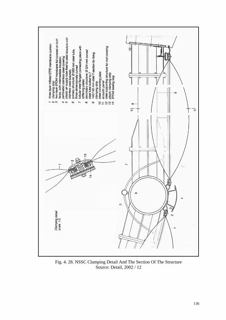
136
Fig. 4. 28. NSSC Clamping Detail And The Section Of The Structure Source: Detail, 2002 / 12

137
4.6. MUNICH STADIUM, Fröttmaning in Munich
Fig.4. 29. External View Of Munich Stadium Source: www.worldstadiums.com
Architects Jacques Herzog and Pierre de Meuron
Client FC Bayern Munich
Dimensions
Stadium dimensions: 258 m x 227 m x 50 m
Stadium circumference: 840 m
Area occupied by stadium: 37,600 m²
Total site area: 171,000 m²
Esplanade dimensions: 600 m x 133 m
DESIGN
The stadium, which was made jointly by Alpine Bau Deutschland GmbH and
Swiss architects Jacques Herzog and Pierre de Meuron, is going to be constructed in the
north of Munich. The construction of building is started in Autumn 2002. The Basel-
based architects won the design contest with their concept for a modern and innovative
football stadium, the like of which has never been seen before. The local media have
already nicknamed the structure the life belt ("Schwimmreifen") or rubber boat
("Schlauchboot") because of its unusual appearance. There is a gastronomy and leisure
areas, halls of fame, 3 playgroups, club shops, office and conference facilities, spacious
media facilities, food services, 2 fan restaurants: the TSV 1860 restaurant in the North

138
stand and the Bayern restaurant in the South stand, each seating approx. 1,500, 1 family
restaurant, 1 terrace restaurant, 1 press cafeteria, 1 cafe-bar inside the building.
In another view, the new Munich stadium, the cost of which was put at 280
million euros (176.3 million pounds), will replace the ageing multi-purpose Olympic
stadium that was built for the 1972 Summer Games and was the stage for West
Germany's final triumph over the Netherlands in the 1974 World Cup. The arena, which
will seat 66,000 and will be completed in April 2005, will also become the home of
Munich's two first division clubs, Bayern and TSV 1860.
This project represents an innovative interpretation of the football stadium of the
future. A cascade of colour can be projected onto the smooth lozenge-shaped exterior,
which takes the form of a curved translucent shell, infusing the structure with an almost
magical poetry. The three-pier seating arrangement guarantees every single one of the
66,000 spectators a close up view of the action, combining raw emotional interaction
with all the comforts of a modern stadium.
Fig.4.30. The Image Of The Munich Stadium (Allianz Arena) Source: www.worldstadiums.com
FOIL PILLOWS
This new football stadium that is Munich's landmark, has long stood as a symbol
of the city around the world. Solutions are now being developed to meet constructional
and safety requirements, especially in respect of the outer skin. In the open areas of the
stadium, the inflated “pillows” provide protection against wind and rain for the 60,000

139
spectators. The thermal separation between the general areas and the heated spaces- for
VIPs, offices, etc.- is in the form of storey- height double-glazing (Fuchs, 2002).
Openable pillow elements are planned for ventilation and smoke extract. More
than 1,000 rhomboid inflated pillows, with an edge length of approximately 8m, are
required for the outer skin. These will be filled with conditioned (dried) air and can
adapt automatically to changing loads from wind and other sources by means of a
pressure regulation facility. Over the roof and to some areas of the façade, the
membrane is transparent, but the main areas are translucent white. With a thickness of
0.2 mm, the transparent membrane would have a light transmittance of about 95 per
cent. Beneath the roof construction, a partially retractable sun shading system is planned
with reflecting and also sound-absorbing qualities (Fuchs, 2002).
This building is a further example of the scope for illumination and lighting
effects that can be achieved with plastic. The facade is fashioned from light. It will be
illuminated according to which team is playing: a white and blue or red and white
pattern will play over the exterior as if it was an enormous LED screen, celebrating the
home side. The light can be made to pulse or simply glow. The entire stadium can
appear white, red or blue. Small blue squares of light race like shooting stars over the
milky shell. The stadium breathes, pulsates in blue, red or white light. Large white and
blue lights circle the stadium, which appears ready for take-off at that moment. There
are a number of lighting scenarios possible, which can be activated to reflect the
ambient mood in the Arena. The beacon summons the approaching fans with their club's
colours, increases the excitement and anticipation. Goals and other major incidents
during the game can be celebrated in light on the facade. And even the areas away from
the immediate vicinity of the pitch are not excluded from the pulsating atmosphere. At
the end of any football day, the light follows the fans home, maintaining the atmosphere
generated by the on-field incidents.
Important questions were raised in respect of the behaviour of the membrane if
exposed to fire or vandalism. The material is fireproof and subject to damage only in the
area of direct projectile attack. Excluding vandalism, the anticipated maintenance
should be very small in comparison with conventional forms of construction. With an
estimated membrane area of 65,000 m2, the stadium will be the largest structure in
Germany covered with ETFE (Fuchs, 2002).

140
Fig. 4.31.Munich Allianz Arena Stadium IPS Detail Source: Detail, 2002/12
Fig. 4.32.Munich Allianz Arena Stadium Inflation and Lighting Detail Source: Detail, 2002/12

141
Fig. 4.33. Munich Allianz Arena Stadium Section Source: Detail, 2002/12
Fig. 4.34 Munich Allianz Arena Project Rendering Red Lighted Source: www.worldstadiums.com

Chapter 5
COMPARISON OF ENVIRONMENTAL CONTROL CRITERIA
AND COST ANALYSIS OF IPS
5.1. Comparison of Environmental Control Criteria of IPS and Conventional Glass
Glazing Systems
Environmentally sensitive, climate controlled buildings promoted the use of
transparent building materials. Glass has been commonly used in glazing applications
for atrium and overhead glazing. However, there are many situations where glass is not
a practical option because of the geometry of the building (Robinson-Gayle, 2001).
Alternatives of glass have been used for glazing with their limited capabilities.
Polycarbonates and other plastic based materials are still in use for glazing purposes.
Although thermoplastic ETFE membrane can be solely used as an architectural
membrane, usage of ETFE as a glazing material is feasible with multilayered
applications. Pillow form saves optimum properties expected from a glazing element. In
order to make a comparison between conventional glass glazing systems (CGGS) and
IPS, their environmental control properties should be discussed.
In the present study, Conventional Glass Glazing Systems are determined as
glass glazings, which have one or more than one pane of glass known as insulating
glasses. CGGS also consist of modified glass panes with coating and gases.
5.1.1. Comparison of Light Transmittance and Visual Perception
Thickness is an important issue for light transmission through glazing materials.
ETFE foil has been commercially produced as sheets, between 50-200 m thickness.
There are three types of foil; clear, opaque and printed. All types of foils have different
light properties. In multilayer applications light transmittance values may change due to
usage of the foil. According to Buitink Technology Co. light transmittance of the clear
ETFE foils are as below:

144
Foil Trade Name Wavelength Light Transmittance
Hostaflon
Visual light 380-780 94-97
UV light 320-380 83-88
Nowoflon
Visual light 380-780 96
UV light 320-380 >95
Table.5.1. Light Transmittance in Specific Wavelengths Source: Butink-Technology, 2002
Glass has been produced in various thicknesses. Production range of glazing
glass is produced commonly between 2 and 19mm in dimension limited with the ovens.
There have been also produced colored glasses between 3 and 10mm.
(www.yildizcam.com.tr) Insulating glasses are usually assembled with 3 and 6mm
glasses. According to Akyürek, Pekışık (2003), single pane of standard 6mm of glass
has approx. 88 percent light transmittance of visible light between 380-780nm. whilst
the standard double glass glazing has maximum 78 percent. Robinson-Gayle (2001)
explains that ETFE foil has a light transmission of between 94-97 percent whilst
ordinary 6-mm glazing transmits 89 percent.
Figure 2.5. also shows the light transmittance rates of double glasses produced
by Şişecam patent in Turkey.
As one can figure out, double and triple layered ETFE has lower light
transmittance values when compared with single layer. However, double and triple
layered ETFE pillow applications are still higher than double glass glazing.
Furthermore natural daylighting takes into account not only the total percentage
of light transmitted but also the range of frequencies transmitted which is important for
color rendering. When compared as whole spectral transmittance, ETFE foil is capable
to transmit the UV light, which is very limited for ordinary glass. This property of the
ETFE foil is important for greenhouse and zoo applications. UV lights have vital
importance for plant life in order to make photosynthesis as well as animal life. Figure
5.1 shows transmission rates of both materials in the spectrum. According to Dr. Fritz,
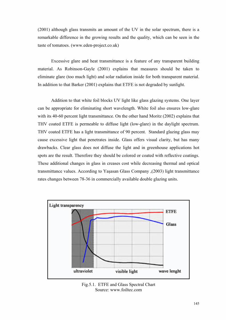
145
(2001) although glass transmits an amount of the UV in the solar spectrum, there is a
remarkable difference in the growing results and the quality, which can be seen in the
taste of tomatoes. (www.eden-project.co.uk)
Excessive glare and heat transmittance is a feature of any transparent building
material. As Robinson-Gayle (2001) explains that measures should be taken to
eliminate glare (too much light) and solar radiation inside for both transparent material.
In addition to that Barker (2001) explains that ETFE is not degraded by sunlight.
Addition to that white foil blocks UV light like glass glazing systems. One layer
can be appropriate for eliminating short wavelength. White foil also ensures low-glare
with its 40-60 percent light transmittance. On the other hand Moritz (2002) explains that
THV coated ETFE is permeable to diffuse light (low-glare) in the daylight spectrum.
THV coated ETFE has a light transmittance of 90 percent. Standard glazing glass may
cause excessive light that penetrates inside. Glass offers visual clarity, but has many
drawbacks. Clear glass does not diffuse the light and in greenhouse applications hot
spots are the result. Therefore they should be colored or coated with reflective coatings.
These additional changes in glass in creases cost while decreasing thermal and optical
transmittance values. According to Yaşasan Glass Company ,(2003) light transmittance
rates changes between 78-36 in commercially available double glazing units.
Fig.5.1. ETFE and Glass Spectral Chart Source: www.foiltec.com

146
Fig.5.2. Spectral Transmission Through Glass Source: Serra. R. 1998
Another factor is picture transmission, which can also be named as visual
transmission. Although a very high amount of light is transmitted the picture rendering
is not equal to that of glass. Double curvature form of the pillows may distort the
lettering whilst it is possible to see the clouds below an atrium roof.
In addition, although the base material is very transparent ETFE foil can be
treated in a number of different ways, similar to glass, to manipulate its transparency
and radiation transmission characteristics. The foil can be over printed with a variety of
surfaces to affect transmission, or printed with graphic patterns to reduce solar gain
whilst retaining transparency, or can incorporate a white body tint to render the foil
translucent. The degree of translucency then can be manipulated by adding additional
layers of foil into the system.
In conclusion, IPS has a better light transparency than conventional glass glazing
systems. However pillow system can interrupt the vision due to curved nature. Visual
transparency is also an ongoing debate for those working with glass. Glass and ETFE
foil can glare and lose its transparency in high amounts of sunlight due to its high
reflectance value. Architects and engineers should consider reflectance property of
standard clear glass that is approx. 8 percent of the visual light. According to Yaşasan,
(2003) this value increases with additional glass panes and coatings between 14 – 9
percent in commercially availability. Reflective coatings have better reflectance values.

147
5.1.2. Comparison of Thermal Transmittance
According to Barker, (2001) multilayered ETFE has better insulation properties
than glass. Figure 3.4 explains the coefficients of heat transmittance of pillows in terms
of its multilayer usage. U-value of the double layer is 3.5 W/(m2*K) whilst Pilkington
and Isıcam double layer glass has an u- value 3.2). On the other hand triple layered
pillow systems’ u- value is appox. 2.0 W/(m2*K) which is better than low-E coated
double glazing units.
Low-e glazing units or tinted glass may adversely affect indoor plants, which
change the spectral quality of the light entering a building. There are also concerns that
the incomplete spectrum of light entering a building through low-e glazing may have an
adverse effect on human health, particularly elderly and the infirm who are forced to
spent a lot of time indoors.
5.1.3. Comparison of Acoustical Performances
The internal environment is considerable more comfortable with lower
reverberant times that if the cladding had been constructed from an acoustically hard
material such as glass. On the other hand ETFE foils are virtually non-existent against
noise. They have sound reduction index Rw between 8-10 dB. In comparison, glass has
a sound reduction between 29-41 dB. ETFE pillows may affect the internal comfort in
positive and negative ways due to usage and design. Therefore designer should be
aware of the acoustical performance of the both material.
Although the ETFE pillows sound reduction index is lower than the glass
glazing, usage of double-glazing does not mean that double glazing contributes to the
acoustical comfort. Addition to that, single glass glazing has better sound reduction
index than of the same width double glazing. The Figure shown below explains the
acoustical performances of single layer glazing.

148
Table.5.2. Sound Reduction Index Of Single Layer Glazing Materials
According to Onat and Sönmez, (2002) there are generally two ways of
improving glass glazing acoustical performance;
Changing the width of the external glazing,
Changing the width of the air space (cavity)
Changing the width of the external glazing up to 10mm increases the acoustical
performance, and maintains an index of 40dB. The increase in width and usage of
double glass glazing units (standard and laminated unit) has commonly limited effects
on acoustical improvement. On the other hand, second method; change in cavity affects
the transmittance of noise. It is explained that 20 cm cavity between panes of 6mm glass
increases sound reduction index to 41 dB. Furthermore increasing the width of a pane
according to the adjacent pane approx. 33% reduces the transmittance of the sound a
little bit more. (Onat and Sönmez, 2002)
Addition to that SP6 gases filled in the cavity improves the acoustical
performance of the double glazing. As explained the usage of the argon and krypton
gases which improves the thermal insulation, does not affect the sound transmittance.
IPS can even be fitted over very noise sensitive areas such as libraries and
offices by fitting rain suppressers designed to reduce rain generated noise below that is
experienced by conventional transparent cladding. Conclusively, glass can be thought as
a secondary skin that may improve the use of pillows in terms of acoustics.
Glazing Type Sound Reduction Index
(dB)
12mm single glass ~31
10mm single glass ~30
6mm single glass ~27
6 mm laminated glass ~29
0.2mm ETFE foil ~10
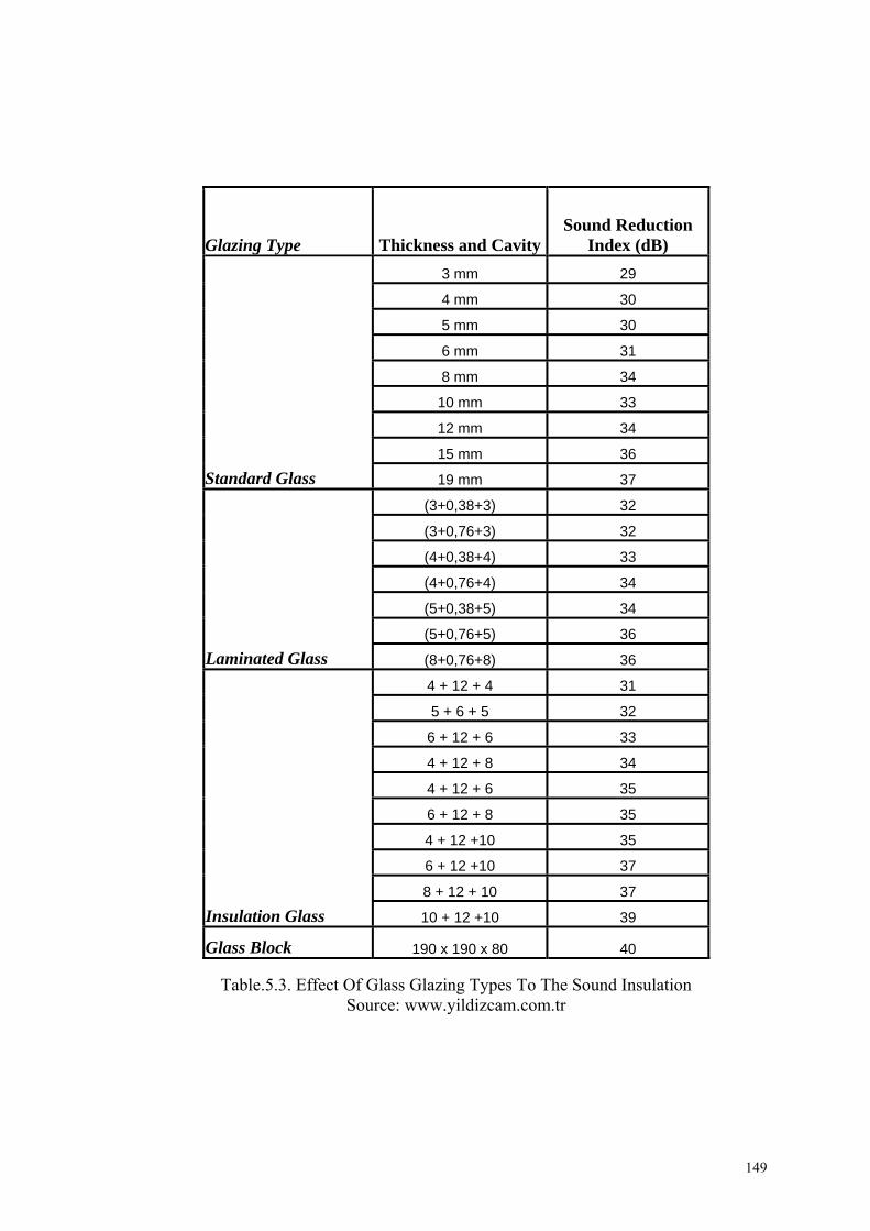
149
Table.5.3. Effect Of Glass Glazing Types To The Sound Insulation Source: www.yildizcam.com.tr
Glazing Type Thickness and CavitySound Reduction
Index (dB)
Standard Glass
3 mm 29
4 mm 30
5 mm 30
6 mm 31
8 mm 34
10 mm 33
12 mm 34
15 mm 36
19 mm 37
Laminated Glass
(3+0,38+3) 32
(3+0,76+3) 32
(4+0,38+4) 33
(4+0,76+4) 34
(5+0,38+5) 34
(5+0,76+5) 36
(8+0,76+8) 36
Insulation Glass
4 + 12 + 4 31
5 + 6 + 5 32
6 + 12 + 6 33
4 + 12 + 8 34
4 + 12 + 6 35
6 + 12 + 8 35
4 + 12 +10 35
6 + 12 +10 37
8 + 12 + 10 37
10 + 12 +10 39
Glass Block 190 x 190 x 80 40

150
5.1.4. Comparison of Safety And Security Performances
In order to make a building light in means of weight, rather than designing
structural elements from concrete or steel, which makes the total construction relatively
heavy-weight, one may think of the lightness of cladding. Lightness can be obtained by
reducing the facade weight as called dead in calculations. Lightweight envelope design
becomes a very crucial issue in this situation. Further more, number of materials has
much importance for façade designers as well as their individual weight becomes the
focal point.
According to Tanno (1997), ETFE foil is flexible material, which can take
extremely high short term loading. This makes it ideal material for use where there is a
risk of explosion. It is able to absorb shock loading without risk of fracture, breakage or
structural overload / collapse. On the other hand glass represents a brittle nature, which
is a major concern in a bomb blast or similar shock load situation. Glass works as a
plate in bending. This structural action is the same irrespective of the type of glass being
used. In a double glazed unit there is some load sharing between the outer and inner
panes with the outer one taking the most of the load.
IPS has been also preferred for its exceptional security properties. As in case of
London Treasury, IPS chosen for its longevity and exceptional resistance to terrorist
threat. ETFE pillows can be manufactured in large sizes and can span a much greater
distance than conventional cladding technologies. Traditional rigid-edge roofing or
cladding has its weak points at the edges. This new system’s high flexibility enables one
to engineer much larger vents and movable structures than conventional technologies
allow. Movement inherits in any building causes boundary edges to fail over time. In
essence, the structure moves, and glass panels expand and contract within the frame and
this differential movement is experienced as a frictional force at the interface between
the two. (Williams, 2002) In pillow system this movement is taken up within the ETFE
material itself. Morris (2002) states that no differential movement is taken up in the
frame.
It has been used several times for windows in rooms subjected to ethanol vapour
and condensation, where pressure surges also occur (as a result of the process taking

151
place in the room). Regular glass windows could not absorb these pressure surges,
which forced the room out of alignment. The problem was solved with ETFE foil
windows (in combination with a special antistatic, gastight stretch ceiling).
(www.buitink-technology.com)
The advantages of ETFE compared to glass are significant reduction of weight,
optimizing the robustness during transportation, achieving a certain flexibility of the
modules and increasing of module productivity by transmitting the total sunlight
spectrum (from UV to IR) to the solar cells. (www.nowofol.de) The lightweight nature
of the pillow saves time in erecting and scaffolding in the construction site. As in the
case of Eden project the structure weighs less than the air it contains. Therefore the
erection was awarded by Guinness Records. The three layer pillow weighs only 1kg/m2
without framing and clamping which is not comparable with glass glazing systems. The
double glazing systems weighs approx.15-30 kg/m2. Therefore conventional glass
glazing systems require a strong frame. A sophisticated base & cap (aluminum and
rubber gasket) glazing system is needed or leaks, especially on overhead glazing, will
surely occur. Often numerous panes of glass are required in a roof slope, resulting in
horizontal mullion bars that dam water and can easily lead to leaks. Insulated glass
should not overhang the eave, requiring a horizontal mullion bar at this location.
Fig.5.3. Workers Installing The Chelsea and Westminster Hospital Roof With a Part Of Frame Glazed with ETFE
Source: AD 65, 1995
IPS is a flexible system. When the clamping is neatly installed, the pressure of
the clamp creates a watertight seal. One of the great advantages of IPS is that gaskets
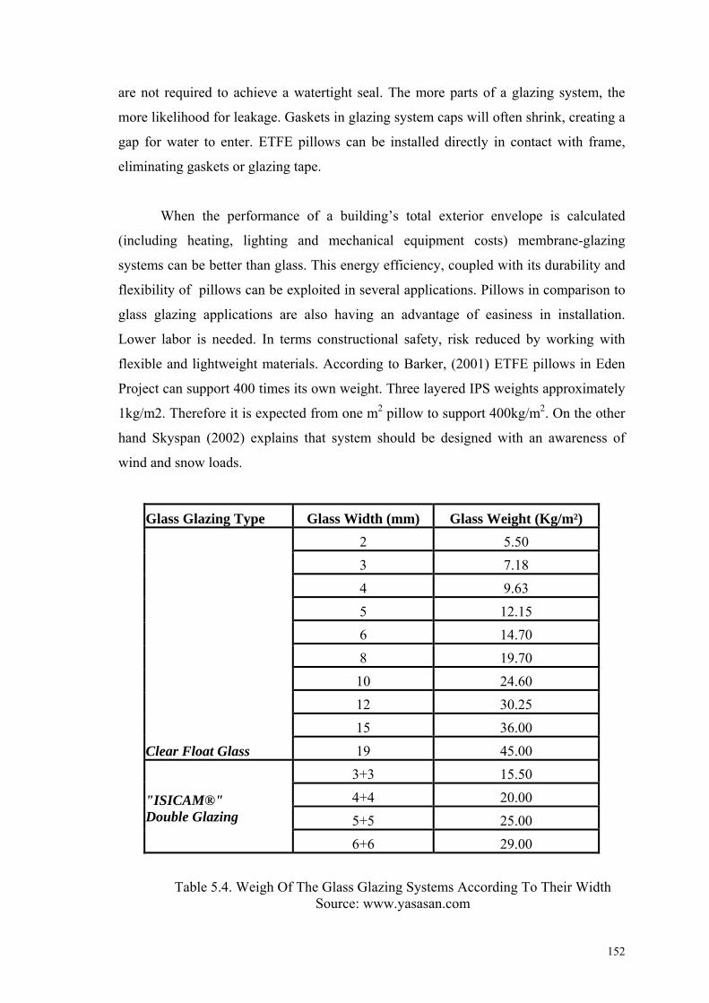
152
are not required to achieve a watertight seal. The more parts of a glazing system, the
more likelihood for leakage. Gaskets in glazing system caps will often shrink, creating a
gap for water to enter. ETFE pillows can be installed directly in contact with frame,
eliminating gaskets or glazing tape.
When the performance of a building’s total exterior envelope is calculated
(including heating, lighting and mechanical equipment costs) membrane-glazing
systems can be better than glass. This energy efficiency, coupled with its durability and
flexibility of pillows can be exploited in several applications. Pillows in comparison to
glass glazing applications are also having an advantage of easiness in installation.
Lower labor is needed. In terms constructional safety, risk reduced by working with
flexible and lightweight materials. According to Barker, (2001) ETFE pillows in Eden
Project can support 400 times its own weight. Three layered IPS weights approximately
1kg/m2. Therefore it is expected from one m2 pillow to support 400kg/m2. On the other
hand Skyspan (2002) explains that system should be designed with an awareness of
wind and snow loads.
Glass Glazing Type Glass Width (mm) Glass Weight (Kg/m²)
Clear Float Glass
2 5.50
3 7.18
4 9.63
5 12.15
6 14.70
8 19.70
10 24.60
12 30.25
15 36.00
19 45.00
"ISICAM®" Double Glazing
3+3 15.50
4+4 20.00
5+5 25.00
6+6 29.00
Table 5.4. Weigh Of The Glass Glazing Systems According To Their Width Source: www.yasasan.com
153
5.2. Cost Analysis of IPS
The reason for using a transparent material is to get high light transmittance
through the material into the building. Thus, transparent glazing also saves a visual link
between inside and outside. Besides free form opportunity of membranes are used for
their translucent property. Traditional glazing material: “glass” has been used for
centuries without any alternative in the market. Improvements in polymer technology:
new plastics and their properties exploited in building construction. Ethylene Tetra-
Fluoro-Ethylene is a copolymer that is adapted to the construction in sheets. Therefore,
this new plastic foil found an appropriate place in architecture as a part of the building
skin, mostly as glazing. Usage of IPS made of ETFE membrane ensures cost benefits in
most cases. According to Vector-Foiltec Company membrane roofs offer a cost
effective and technically superior alternative to conventional structures.
Usage of pillow systems is explained in previous chapters. The results of the IPS
usage are important in terms of building economy. Due to the nature of the system,
costing of ETFE foil systems and all other membrane materials must be looked at as an
entire cladding solution rather than as a direct replacement for any particular material.
As in other glazing systems the material used in the system are important in the total
cost of the system. Therefore, systems’ cost can be explained through the dominant
material, ETFE membrane. Much of the systems properties are in close relation with the
membrane itself.
Cost efficiency of the system has to be discussed in three ways:
the cost of Inflatable Pillow System itself,
the cost occurred by the construction technique of the building skin,
and its effect to the lifetime cost of the building. (Maintenance Cost)
Although the costs per square meter are given examples of the IPS above, that
may be problematic to determine the real cost of the building. Due to several advantages
of the system, total costs of a building can be reduced. Williams, (2002) explains that
IPS structure costs 30 to 50 percent than traditional steel and glazing systems. Addition
to that, Tanno (1997), explains that pillow system with ETFE foil can be installed
roughly half the price of a conventional high performance glass envelope.
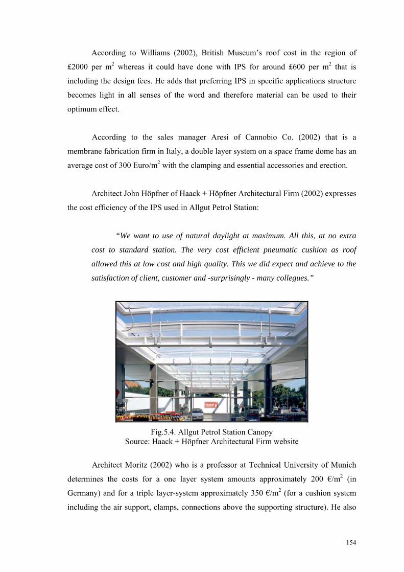
154
According to Williams (2002), British Museum’s roof cost in the region of
₤2000 per m2 whereas it could have done with IPS for around ₤600 per m2 that is
including the design fees. He adds that preferring IPS in specific applications structure
becomes light in all senses of the word and therefore material can be used to their
optimum effect.
According to the sales manager Aresi of Cannobio Co. (2002) that is a
membrane fabrication firm in Italy, a double layer system on a space frame dome has an
average cost of 300 Euro/m2 with the clamping and essential accessories and erection.
Architect John Höpfner of Haack + Höpfner Architectural Firm (2002) expresses
the cost efficiency of the IPS used in Allgut Petrol Station:
“We want to use of natural daylight at maximum. All this, at no extra
cost to standard station. The very cost efficient pneumatic cushion as roof
allowed this at low cost and high quality. This we did expect and achieve to the
satisfaction of client, customer and -surprisingly - many collegues.”
Fig.5.4. Allgut Petrol Station Canopy Source: Haack + Höpfner Architectural Firm website
Architect Moritz (2002) who is a professor at Technical University of Munich
determines the costs for a one layer system amounts approximately 200 €/m2 (in
Germany) and for a triple layer-system approximately 350 €/m2 (for a cushion system
including the air support, clamps, connections above the supporting structure). He also

155
adds that the variable shading system is more expensive due to sophisticated
pneumatics.
In addition to that, expensive costs for transportation reduced by the light and
thin nature of the pre-assembled frames in factory. The risks like cracking of a glass
pane in transportation are not available. Therefore payments for insurance will be cut
down during construction. Due to lightweight frames, labor prices like handling and
erection will be much more lower than any other traditional system. In some cases
scaffolding is not needed, which will affect the cost of construction.
One of the major opportunities that system ensures is the high light
transmittance. Glazing does not block the light that enters through the structure. Very
high amount of the light reaches to the depths of the building. So that, there will be a
deduction in lighting expenses. With the awareness of the system advantage from the
design phase, IPS saves extra expenses for electrical appliances. Less electrical
appliances need low-maintenance and change in time. According to Akyürek and
Pekışık (2003), glass used in botanical gardens and greenhouses is commonly 3 mm and
4 mm float glass. They added that one percent (%1) increase in light transmittance
results as a one percent (%1) increase in production or crop.
Hampshire Tennis And Health Club has a white foil which gives the high levels
glare free light for the players. Double layer pillows that are consisting of white and
clear foils save to the club over ₤20.000 per annum in the lighting costs while giving
spectacular appearance form outside.
In the case of Westminster and Chelsea Hospital that was covered by IPS, each
running fan has an electricity consumption of 100W for approx. 500 m2 (Cook, 1994).
According to Cook, (1994) at Westminster and Chelsea Hospital, London, such a
system was developed and incorporated into a sub-frame of purpose made aluminium
arches to provide an extremely cost effective solution to the problem of enclosing a
deep central atrium. According to Polat, (2003) from Texlon Firm in Switzerland,
Westminster Chelsea Hospital Atrium, which is the world’s largest naturally ventilated
atrium, saves ₤10.000.000 in heating and ventilation.

156
Fig.5.5. Hampshire Tennis And Health Club Source: www
In addition Williams explains that in Eden project there is an electricity
consumption of 100 Watts for 1000m2 where the fans are running half of the day. As in
case of Eden Project, solar powered buildings with photovoltaic panels may easily solve
electricity expenses. Tanno (1997) explains that the energy consumption used by the
inflation units is minimal because the blower units only need to maintain pressure, they
do not nee to create air flow. As explained in chapter 3, two electric motors share the
working hours by switching. In this way, consume 50 Watts of energy per day.
Furthermore Robinson-Gayle et. al.(2001) agrees that electric fan uses a small amount
of energy approximately 50 Watts for 1000m2 which equals to half of the consumption
of a light bulb.
Another major deduction is possible with IPS structures. As known, energy is a
major expense for buildings in their lifetime. Heating and cooling systems are
responsible for the energy consumption. Heat insulating factor of IPS (lower U-value)
helps uncontrolled heat flow through building skin. This property of IPS works also in
summer season as heat shield. IPS doesn’t let excessive heat flow through the glazing.
Therefore system reduces cooling expenses of the building. As known, cooling is an
expensive issue than heating the building. IPS reduces cooling and heating system

157
equipments in number. Eventually, high costs of those systems can be eliminated from
the design phase. Decreased equipments in number occupy less space in the building.
There can be saving for the spaces not constructed or for the narrow structure due to
fewer loads.
Low-maintenance is an additional option of the system. An annual maintenance
from the outside of the glazing is enough in most cases. According to Foiltec there is
one known customer having cleaning for the lower layer once in a five-year period.
Inflated ETFE sheets are extremely resistant to dirt. Material has ability to self-cleanse.
They do not absorb any chemical and dirt. IPS does not need monthly cleaning.
Therefore mud, pest, dust are washed away with wind and rain, further reduces the
lifetime costs to very low levels. However Skyspan recommend s a periodic cleaning
depending on the location. According to Watts (2001), the internal face of the pillow
within the building can became slightly dirty due to small amounts of static electricity
that can be presented in the material. According to Tanno (1997), internal foil is usually
cleaned on a 5-10 year cycle depending on the dirt in the internal atmosphere. Therefore
expensive internal access equipment is not required for cleaning, which may be solved
by low-tech, cheap methods like rope access as accost effective solution. Tanno,
discusses the extruded materials smoothness and its’ anti-adhesive property, and advices
an external cleaning frequency of more than 4 years. In comparison with glass glazing
systems, the self cleaning property of IPS saves maintenance cost and initial investment
costs for cleaning expensive equipments.
Addition to those cost deductions described above, ETFE sheets are highly
durable. Most producers and manufacturers are expecting a life span more than 20
years. Furthermore Skyspan, which is the manufacturer of Eden Project, is giving 60
years of life expectancy for the total building skin. Therefore IPS does not need to be
renovated in short terms.
Lightweight nature of the ETFE pillows also maintains a cost advantage for
architects and designers. IPS underlying structure does not need to be very heavy. Thus,
a decrease in supporting structure and narrow elements of the structure are an additional
deduction in expenses of the building. Whenever it’s used partly or a total enclosure,
due to less loading to the structure, the foundations can be decreased in size. The soil

158
under the lightweight structure does not necessitate any special treatment. Furthermore
the entire system can be realized by a scaffold free construction technique as previously
did in Eden Project. Therefore application of the system does not need high lifts in
many cases that should be owned or rented by the contactor. According to Williams
(2002), IPS obtains a reduction in size and quantity of material used for the roof support
structure. He adds that commonly about 10 times the amount of the steel is used in
columns and beams than is needed for support purposes, primarily just to provide
stiffness. If one considers the roof weight approx. 3kg/m2, than it has been better
understood that the requirement for self-support effectively becomes the only criterion
for the structural members.
As in case of Eden Project, in Cornwall, If glass had been used for the entire
structure it would have needed three times as much steel to support it. Thus designers
chose to use IPS made of ETFE. (Cornish Guardian, 2000)
Lightweight nature of IPS is also a cost beneficial situation for movable
structures or ventilation holes in the structure. Thus, any ventilation or movable part
does not need high-powered hydraulic systems that may increase cost.
In case of a movement of the soil or a limited earthquake, IPS absorbs some of
the movement between frames. Soft pillows can shrink and then can return to their
original situation without any deformation in the glazing. There is no need to replace the
glazing for those limited situations. In addition to that IPS brings a solution to the
expensive movable joint need. Williams explains that IPS is soft-tech system with its
real soft nature rather than a high-tech glazing system. This saves maintenance cost of
building skin in lifetime.
Although wind control property of IPS is discussed in previous chapters, IPS
structure is a cost effective solution for glazing. In case of strong wind and wind
suction, pillows absorb some of the effect of wind as they adapted themselves in
earthquake. In this way, they only transmit a limited part of the wind load to the
structure. Structure becomes narrow, and thus results as a cost benefit. Although it’s
hard to calculate the positive effect of the pillows in to the structure measurements, it is
commonly used as a factor and will be learned in progress by trial-error.

159
Tearing resistance against propagation is another positive opportunity that saves
deduction in lifetime expenses. In case of an attack or a small damage to the pillow can
be repaired by ETFE foil adhesive tapes. The whole glazing does not need to be
replaced by a new pillow.
Besides that, one of the very important properties obtained by the ETFE foil is
the welding capability of the membranes. That saves a great labor for clamping and
fixing the pillows in to the frames.
Fig.5.6. Adastral Houses High-Tech Atrium lets the noise out, Warner Bros. Source: www
As pillow glazing is very light, single layer with a mass of 350 g/m2, it is
acoustically soft and doesn't reflect internally generated noise back to the occupants.
This natural feature of cladding means that cost intensive counter measures such as the
integration of acoustic absorbers into the internal walls are usually completely
unnecessary.
Hanover Social Housing that is a social housing project organizes budget
accommodation around a shared communal garden roofed in an IPS variable skin.
According to Vector Group the savings in the internal cladding to the residential blocks
more than paid for the roof and internal landscaping, making the scheme a highly cost
effective in terms of maintenance.

160
Fig.5.7. Hanover Social Housing Source: www
In the case of Arnheim Zoo built in 1981, IPS maintains self-sustaining man
made ecology. No other chemical fertilizers and insecticides are needed to sustain the
environmental criteria. As described by Vector Group, zoo has been tuned over the last
ten years to operate completely naturally that means virtually no-maintenance.
Fig.5.8. Arnheim Zoo Internal Views Source: www

161
According to ETFE producer Nowofol Company (2003) transparent film prices
are given due to film thickness. It is determined that additional costs like slitting hold
5% of the cost. There can be proportional costs for amount of edge trimming in
correlation to standard width 1550mm.
Prices f. Quantity
f. Thickness 100 m 25m 30m 50m 100m 150m 200m 250m
< 10kg < 60 m2 3,15 3,80 5,85 11,75 17,60 23,45 29,30
10kg 60 m2 2,90 3,50 5,45 10,85 16,30 21,70 27,15
50kg 300 m2 2,80 3,35 5,15 10,35 15,50 20,70 25,80
100kg 600 m2 2,70 3,20 5,00 10,00 14,95 19,95 24,95
250kg 1500 m2 2,60 3,10 4,75 9,55 14,30 19,10 23,85 *All prices are Euro/m2
Table 5.5. Price List of Nowoflon ET-foil 6235 Source: Nowoflon Technical Data Sheet, 2003
On the contrary white foil with various thickness between 100-250m, which
has a light transmittance approx. 50-55%, is only 1,00 Euro/ m2. In addition primer
coating to one side like bonding with EVA (Ethylene Vinyl Acetate) in thickness
150m / 775mm width costs 7,50 Euro/ m2.
ETFE is completely recyclable material. Furthermore many other components of
IPS can be produced from recycled material (Vector-Foiltec, 2002). ETFE foil can be
easily recycled by heating it to the melting temperature, which is approx. 270oC. But,
virgin ETFE needs to be added at the point of manufacture. Foils may also be disposed
of in a landfill situation – apart from a very small amount of Hydrogen Fluoride gas
(HF) released over time, material is essentially inert.
Energy efficient is an important issue for the IPS. Energy efficiency of the
system can be argued due to its embodied energy and energy conservation. According
to Vector Group, the embodied energy of the system is very low. However energy
conservation is very high with its high insulation and solar gain. On the other hand
according to Erengezgin, (2002) aluminium itself is a material that its embodied energy
is very high than most of other conventional construction material in the sector.

162
However, aluminium profiles has a negative effect on the subject, it has been preferred
almost in every cladding and glazing application.
Bespoke production systems are generally considered as expensive applications
in construction sector. Extrusion technology, wide clamping system choice and
recycling ensures a deduction in production. Besides the high initial costs of the
bespoke system, the entire building becomes cost effective with IPS in lifetime.
The lightweight foil often results in cost savings for the underlying structure, and
spans and shapes can be accomplished that would not be possible with glass.
(www.buitink-technology.com) IPS self cleanses under the action of rain. Thus results
as a decrease in lifetime costs of the building. Most of the curtain wall applications need
special care and extra systems for regular cleaning. ETFE foil has a very low surface
tension. Dirt and mud will be swept away in the first rain falls down.
According to Foiltec Company, pillow form saves a highly energy efficient
cladding due both to its environmental performance and its low embodied energy,
which is less than 1% of conventional technologies. Although designers consider the
resource consumption, which is used as energy in buildings in their lifetime, embodied
energy is another point that they should be aware of. Embodied energy of the materials
can be determined that the amount of energy use to produce material and includes the
energy associated with mining, mineral purification and processing. (Robinson-Gayle
et. al., 2001)
Embodied Energy ETFE Foil 6-mm Float Glass
EE (GJ/ t) 26.5 20
EE per m2 (MJ/M2) 27.0 300
Table 5.6 Embodied Energy For ETFE Foil And Glass Source: (Robinson–Gayle et. al. ,2001)
As shown in table 5.6 although embodied energy difference per tonne is not in
huge amounts between ETFE and glass, embodied energy of glass in m2 is
approximately 10 times more than ETFE foil.
163
The much greater pillow sizes minimize structural shading. This is also related
with the production limits of ETFE foil. ETFE Foil has a width of 1.55m, which can be
easily weld one by another. ETFE film can be joined by thermal impulse welding at 30 oC. That application extends the limits while glass and other substitutes have to be
connected with extrusions, clamps and bolts.

Chapter 6
CONCLUSION
This study, which focuses on an alternative glazing system in construction
technology, has aimed to discuss applicability and feasibility of the inflatable pillow
system as a substitute for conventional glass glazing system that has been used in
architecture by an objective point of view. Exploring the varying sources of reference,
the study aimed to compare both systems of glazing by investigating their performance.
Most of the constructional materials and systems, even glass glazing has been
transformed by the increasing energy consciousness of the consumers at the end of the
20th century. Glass has been used for centuries, which became an industrial material
with so many varieties in the building sector. It has been used without alternative
because of its transparent nature. Transparency and high light transmission rates of the
advanced glass glazing improved its architectural applicability in contemporary
buildings. In the line with the increasing technology and demand, glass and plastic
based materials such as polycarbonate panels, fibreglass and PVC foil, have improved.
The Inflatable Pillow System (IPS), which is materialized by ETFE that is a
thermoplastic fluoropolymer, is used as alternative to glass glazing system in recent
architectural applications because of it’s economical life-span, safety and security
criteria and low maintenance cost. The ETFE, which is produced as a folio in different
thickness by the way of extrusion, use both as a one layer isotropic architectural
membrane and also use as multi layered. The effectiveness of IPS depends on the
number of layer, the thickness of folio and the usage of membrane material. ETFE foil,
which it has low embodied energy during production, is sustainable and therefore
ecologic material.
It is also possible to say that, IPS is so suitable and effective for spaces that they
don’t shelter people continuously in it such as greenhouses, botanical gardens and zoos.
Besides that, when it is considered that the provided easiness on maintenance, reduced
operating and maintenance costs; applying this system for school, hospital, sport halls,

165
shopping and entertainment centres will be so useful. This system also use for atriums
and roof lights.
IPS consist of an assembly of the two or more ETFE foil layers welded together
and put as an infill inside a special manufactured frame, which are supported with
lightweight structural elements. Pillows are air supported by the help of pneumatic fan
units. Pillow system is compared with the conventional glass glazing systems according
to the their technical properties, manufacture and application processes, and
environmental control criteria which are optical thermal, acoustic performances and
security properties. In the line with the information got; the results are summarized as
below:
Comparing with the conventional glass glazing systems, IPS provides a more
flexible design opportunity. While easy welding nature of foil saves bigger
amounts of glazing surface, the flexible nature of the system provides nonplanar
applications possible without the need of a second process. In other words, the
usage of pillow system made of ETFE foil saves architectural freedom
comparing to the conventional systems in terms of building envelope. In
addition to that lightweight nature and less detail solutions obtain a easy
installation and easy maintenance construction method.
In contrast with the glass panes ETFE foil is very lightweight. One layer weighs
350 gr./m2, while ordinary 3mm glass pane weighs approx. 7 kg/m2. Therefore
IPS transmits fewer loads to the main structure where it is used. Pillow system
reduces structural loads and movements and also does not have thermal tensions
on its surface as glass glazing systems. In addition, flexible and lightweight
nature of the IPS system reduces the risk factor that will be formed during
transportation, application and also reduces the risks of accident during
earthquake and similar hazards. On the contrary usage of glass has some
obstacles in particular applications.
Mechanical properties of the IPS give opportunity to glaze wider surface area
when compared with glass glazing systems. Although the width of foil (1.50m)
is smaller than the commercially available glass width, the welding property
166
makes the membrane extended up to 7.5m for particular applications. Therefore
supporting elements; muntins and mullions are excluded from the design, which
reduce detail problems and structural shading in terms of aesthetics and
efficiency. However, as a result of fewer loads bearing capacity of the
membrane, pillow forms made of ETFE are not capable for the cladding
purposes without support. Advanced foil material of the future that has high load
bearing capacity, will possibly cover wider areas with pillow system.
In contrast with the pneumatic systems, inflatable pillow system needs support
for the pillows. But this minimized support is not as much as in glass systems.
Air supported pillows’ shape provides a structural opportunity against lateral
forces such as wind and earthquake. Pillows absorbe some of the pressure of the
wind and therefore transmits less forces to the main structure of the building,
which also reduces extra structural elements and need for a heavy foundation in
the construction. Flexibility of the membrane itself also absorbs the movements
and reduces the need for the movement joints.
IPS provides better light transmission compared to glass glazing system. By
means of the ETFE folio, which is usually produced transparent, can be
produced opaque or patterned, in question light transmission can be controlled.
This material can pass highly rate of the UV rays, which are between 280-400
nm. in spectrum according to glass. ETFE is an ideal material especially for
green houses, atriums and roof lights. Besides that, by the way of “ variable
Shading Method” that can only be realized on three layered applications, there
can be designs that are environmentally sensitive to indoor and outdoor
conditions. Thus, the light and heat gain of building can be tuned manually or
automatically with the help of sensors.
IPS provides better thermal performance compared to glass glazing system. The
heat transmission value of two and/or three layered applications is similar with
glass. This system is water and air proof and it has minimum joints and this
provides heat conservation for building. The value of heat conservation can be
decreased by adding the layers to the system and preferring selective coating

167
materials. In addition to that, in terms of environmental control criteria the IPS
give most ideal results in temperate climates.
IPS shows worse acoustical performance compared to the glass glazing system
although it is up to design. Because of the acoustically soft nature of the
material, sound can penetrate to the both sides of the building envelope without
any obstacle. In contrast with the glass panes system saves lower reverberation
times that increases the internal comfort. This may be an opportunity for
designers that should be exploited in the early design phase in terms of
aesthetics and economy. While acoustic property can be seen as a disadvantage
in particular buildings such as office buildings, it can be an advantage for the
buildings such as botanical gardens.
ETFE folio prevents flames to spread, delays the structure of the building to
collapse and proves high fire safety compared to the glass glazing system. The
folio doesn’t drip molds during fire, but it may have a problem of getting loose
at 60o C. Because the material doesn’t have a fragile structure like glass, in
spaces where there is a risk of implosion the strong pressure of implosion is
reduced.
IPS whether there is life inside or not the air pressure must always be constant,
which requires the air pumps working continuously, has a negative influence on
the building economics compared to the glass glazing system. Because of this
case the electricity expenses can be solved with the use of photovoltaics. In
opposite condition, the folios may inflate like sails or may deflate. This
uncontrolled situation may cause the material to be worn out in shorter time.
IPS has a high investment cost at he beginning but reduces the upkeep and
undertaking expenses in building’s economical life compared to the glass
glazing system. Because the material has easy application and the expenses for
transport and insurance is less, the performance of investment and design
expenses when compared to glass systems the material offers a great cost
advantage.

168
As a result, ETFE folio end Inflatable Pillow Systems, the latest results of the
researches of the mobile process of construction and material sectors has brought up a
new dimension for conventional glass glazing systems. This system is an ideal glazing
system with its high level of environmental control criteria, technical performance,
usage period and the low expenses but it hasn’t taken the place of glass systems yet.
Beside the advantages offered to the building, the system has some disadvantages, may
be ideal for limited applications.
Briefly, the use of transparent, lightweight and elastic material and glazing
systems made up of this material as building envelope or as a part in the building
reduces the distance between the terms of “glazing” and “membrane coating”, or maybe
in future the boundary between these systems may be removed. So, in short time it’s not
expected that these systems will occupy the place of conventional glazing systems, it’s
projected that Inflatable Pillow Systems will be understood by designers and the
applications which are related to will increase.

REFERENCES
1. Addis, B., “Westminster & Chelsea Hospital Roof”, in The Art Of The Structural Engineering, (Artemis London Limited, London, 1994)
2. “Administration Building in Munich”, Detail 6, 2000
3. Akçakoca, 1996 4. Aksaray Yenisey, N.., “Giydirme Cephe Konstrüksiyonu”, (Yayınlanmamış
Yüksek Lisans Tezi, Gazi Üniversitesi, Fen Bilimleri Enstitüsü, Ankara, 1995)
5. Akyürek, Y., Pekışık, G, “Güneş, Uygarlık ve Cam”, Yapı 258, 2003
6. Allen, I., “A Taste of Eden”, Architects’ Journal, 2001
7. Barker, D., “Eden of UK”
8. Barthel, R., Markert, H., “Large-Span Roof Structures”, Detail 5, 2001
9. Behling, S., “Multilayered Glass Roofs” in Glass: Structure and Technology in Architecture, (Prestel Verlag, München, 1999)
10. Behling, S., “Innovative Façade Systems” in Glass: Structure and Technology in
Architecture, (Prestel Verlag, München, 1999)
11. Benton, C.C., “Architecture Revisited: On listening to Buildings” in Dimensions Of Sustainability, (E & FN SPON Press, 1997)
12. Brookes, J.A., Grech, C., The Building Envelope - Applications of New
Technology Cladding, (Butterworth & Co, 1990)
13. Button, D., et.al., “Glass in Building-A Guide to Modern Architectural Glass Performance”, (Butterworth Architecture, 1971)
14. Cook, M.J. et.al., “Cushion Roof System for a Hospital Atrium, London”,
Structural Engineering International 1, 1994
15. “Covered Courtyard in Vienna”, Detail 7/8, 2002
16. Daniels, S.H., “Improving Glass Performance – New Films,Coatings, And Laminates Make Glazing Safer, Stronger, And More Energy-Efficient Without Sacrificing Transparency”
17. Demetri, G., “Curtain Walling and Glazing”, AJ Focus March, 1996
18. Fuchs, R., “New Football Stadium in Munich – A Plastic Skin”, Detail 12, 2002
19. Gayle, S.R., “ETFE Foil Cushions in Roofs and Atria”, Construction and
Building Materials 15, 2001

170
20. “Glass and Architecture”, Detail 3, 1998
21. de Grey, S, “Ecology in Architecture” in Dimensions Of Sustainability, (E & FN
SPON Press, 1997)
22. Gölen, A., “Hafif Metal ve Cam Hazır Elemanlarla Yapılmış Çağdaş Cephelerin Türkiye’deki Uygulamaları ve Sorunları”, (Yayınlanmamış Yüksek Lisans Tezi, Selçuk Üniversitesi, Fen Bilimleri Enstitüsü, 1990)
23. Harris, T., “How the Eden Project Works”
24. “Herkes İçin Cennet”, Domus, 2002
25. “Information Centre in Kochel am See”, Detail 12, 2002
26. “Intelligent Glass Façades-More Than Just Weather Protection”, Detail 3, 1998
27. Keyworth, B., “Doors and Windows”, AJ Focus March, 1996
28. Krewinkel, H.W., “Glas”, Detail 3, 1998
29. Kronenburg, R., “Powerhouse: UK London – Branson Coates Architecture”, AD
– Portable Arcitecture 68, 1998
30. Lyall, S., Architects’ Journal April, 2002
31. Moritz, K., “Materialeinsatz und Konfektionierung von Membranwerkstoffen”, Stahlbau 69, 2000
32. Moritz, K, “Covering Up – An open and shut case”, Stadia – Showcase Special
October, 2000
33. Moritz, K, “Membrane Materials in Building”, Detail 6, 2000
34. Moritz, K, “Membrane Konstruktionen – die Entdeckung einer neuen Formensprache”, Leonardo- Online 1, 2000
35. Moritz, K., Barthel, R., “Transparent Architecture-Building with ETFE
Membranes”, Detail 12, 2002
36. “National Space Centre Museum in Leicester”, Detail 12, 2002
37. Oesterle, et.al., Double- Skin Facades, (Prestel Publishers, 2002)
38. “Pavilion at Earth Centre, Doncaster”, Detail 6, 2000
39. Pfaender, 1983
40. “Products”, Architects’ Journal June, 2002

171
41. Rein, A., Wilhelm, V., “Membrane Construction”, Detail 6, 2000
42. Richards, B., “Design Antenna”, Detail 3, 1998
43. Robbin, T., “Membranes” in Engineering a New Technology, (Yale University
Press, London, 1996)
44. Robbin, T., “Materials” in Engineering a New Technology, (Yale University Press, London, 1996)
45. Sarıay, İ, “ ”, (Yayınlanmamış Yüksek Lisans Tezi, Dokuz Eylül Üniversitesi,
Fen Bilimleri Enstitüsü, İzmir, 19..)
46. Schock H.J., Soft Shells, Design and Technology of Tensile Architecture, (Birkhauser, Basel, Switzerland, 1997).
47. “Skin Architecture”, a+u 385, 2002
48. Stonehouse, R., “Dwelling With The Environment: The Creation Of Sustainable
Buildings And Sustaining Situations Through The Layering Of Building Form And Detail” in Dimensions Of Sustainability, (E & FN SPON Press, 1997)
49. Şişecam Architectural Glass, 1996
50. “The Eden Project”, Architectural Design Architecture of Ecology, 2003
51. The Greening Curve- Lessons Learned in the Design of the New EPA Campus in
North Carolina, (2001)
52. Türkseven, İ., “Camın Yapı ve Mekan Tasarımı Üzer,ndeki Etkileri”, (Yayınlanmamış Doktora Tezi, Dokuz Eylül Üniversitesi, Fen Bilimleri Enstitüsü, İzmir, 1996) ,
53. Türkseven, İ., “Üçüncü Bine Doğru .Mimarlıkta Cam”, Yapı 200, 1998
54. Watts, A., Modern Construction Handbook, (Springerwien Press, Newyork)
55. Wigginton, M., Harris, J., Intelligent Skins, (2002)
56. Williams, A., “Survival of the Fittest”, Architects’ Journal, 2002
57. Williams, A., “The Sky’s The Limit”, Architects’ Journal, 2002
58. Wooley, T., Green Building Handbook 2, (E & FN SPON Press, London, 2000)
59. Yeang, K., “The Skyscraper, Bioclimatically Considered” in Dimensions Of
Sustainability, (E & FN SPON Press, 1997)
60. Onat N., Sönmez. A, “Performance of Curtain Walls” in Egemimarlık 4 2002

172
World Wide Web Sites
1. www.anthonyhuntassociates.co.uk
2. www.apexphoto.com
3. www.architectureweek.com
4. www.architype.co.uk
5. www.arplus.com
6. www.arup.com
7. www.axon-cable.net
8. www.bauwenmetstall.com
9. www.birdair.com
10. www.boedeker.com
11. www.bo-hightex.com
12. www.bouwenmetstaal.nl/hallen
13. www.buitink-technology.com
14. www.burohappold.com
15. www.canobbio.com
16. www.ceno-tec.de
17. www.chemfab.com
18. www.covertex.de
19. www.crestcoating.com
20. www.cwct.co.uk/facets
21. www.dupont.com
22. www.dyneon.com
23. www.eden-project.co.uk
24. www.edenproject.com
25. www.efficientwindows.com
26. www.emog.com
27. www.ersinger.com
28. www.festo.com
29. www.fluon.com
30. www.fluoropolymers.com
31. www.foiltec.com
32. www.gra-pa.at/projects/NeueBaustoffe

173
33. www.grimshaw-architects.com
34. www.haackhoepfner.com
35. www.heytex.com
36. www.hok.com
37. www.ims-institute.org
38. www.ipl-team.de
39. www.kochhightex.de
40. www.kochmembranen.com
41. www.lab42.architectur.uni-siegen.de
42. www.lt.arch.tu-muenchen.de
43. www.membranstatik.de
44. www.nhm.ac.uk/darwincentre
45. www.nce.com
46. www.nowofol.de
47. www.pfeifer.de
48. www.plantec-engineering.de
49. www.plastics.saint-gobain.com
50. www.plastpolymer.h1.ru
51. www.saintgobain.com
52. www.skyspan.com
53. www.techtextile.com
54. www.teflon.com
55. www.tensy.com
56. www.texlon.ch
57. www.vector-foiltec.com
58. www.vsindutex.com
59. www.vsp.com
60. www.worldstadiums.com
61. www.yasasan.com
Personal Scientific Conversations and Seminars
1. Erengezgin, Ç., 2001-2002, Seminar, “Energy Efficiency”, Izmir Construction Fair
2. Höpfner, J., 2003, Lydia Haack & John Höpfner Architekten

174
3. Lutzeier, A., 2003, Skyspan, Sales Manager
4. Moritz, K., 2003, Technical University of Munich, Scientific Assistant
5. Aresi, A., 2003, Canobbio Company, Sales Manager
6. Temiz, D., 2003, Seminar, “Curtain Walls and Details”, Izmir Chamber of
Architects
7. Morris B., 2003, Vector- Foiltec, General Manager

Fig. 3.10. Details of Arena Center, Halle, Amsterdam (Arch: Benthem Crouwel) Source: www.bouwenmetstaal.nl/hallen

Fig. 3.11. System Detail Of Pillow System Source: www.texlon.ch

Fig.3.21. Workers Installing Etfe Foil Panels In The Dome Ceiling Source: www.apexphoto.com
Fig.3.22. Each ETFE pillow is secured in the steel framework Source: www.apexphoto.com

Fig. 3.23.Bocholt Leisure Pool Source: www.foiltec.com
Fig. 3.24.Avifauna Butterfly House Source: www.vsp.com

Fig. 3.25.Installation and Clamping Of Pillow System Source: www.buitink-technology.com
Fig. 3.26.Skyspan HQ Source:www.skyspan.com

Fig. 3.32. Earth Center External View Source: Detail, 2000 / 6
Fig. 3.33. Earth Center External View IPS Close Up Source: Detail, 2000 / 6

Fig. 3.34. Earth Center IPS Detail of the Roof and Facade Source: Detail, 2000 / 6

Table 3.1. Pillow Properties of The Particular Applications
NAME OF THE PROJECT STRUCTURE SPAN SIZE PILLOW SHAPE & SIZE INT. PRESSURE
EDEN PROJECT Geodesic dome Hex-tri-hex,
10-11m
MASAOLA RAINFOREST HOUSE Arched steel truss 106m - 4m trans. Non-planar Rectangular,
3 / 23m, 4.2 / 23m
WEST. CHELSEA HOSPITAL Barrel-vault steel 18-20m Rectangular,
3 / 4m 400-500 pa
MUNICH ALLIANZ ARENA Grid steel frame Rhomboid shaped
8m edge length
HEMPSHIRE TENNIS HEALTH CLUP Uni-axial cable net 36 Non-planar rec.,
3 / 18m
GERRY WEBER TENNIS STADIUM Grid steel frame Rectangular 200 pa
WATER PAVILLION AT EARTH CENTER Steel frame Rectangular
NATIONAL SPACE & SCIENCE CENTER Grid steel frame 14 m Non-planar rectangular,
3 /20m
HELLABRUNN ZOO Prestressed cable net Non planar,
max. 2.5 / 18m 250-350 pa
BRAUN AG OFFICE ROOF SKYLIGHTS Steel frame Rectangular,
5 / 12m
FESTO AG Barrel-vault steel 13.5-21.0m Non-planar

Project Name Place Country Date Number of
Foil Foil Width Foil
Transparency
Eden Project Cornwall, London UK 1995-2000 3
Hellabrunn Zoo (Lion House) Hellabrunn,Munich Germany 1995 2 200/200m
Masaola Rainforest House Masaola, Zurich Switzerland 2003 3 R200/100/180, F200/100/150m
Pavillion at Earth Center (Waterworks) Doncaster UK 2002 3 white inner foil Duales System Deutschland DSD Expo2000 Germany 2000 3 VST*
Westminster Chelsea Hospital Westminster UK 1992 3 200/30/150m
Festo AG Esslingen, Stuttgart Germany 3 VST*
National Science and Space Center Leicester UK 2001 3
Allianz Arena Munich Stadium Fröttmaning N. of Munich Germany 2005 3 200/200/200 (?)m WRB illuminated
Hempshire Tennis and Health Club Southampton UK 1992 3 white foil
Gerry Weber Tennis Stadium Halle, Westfallen, North Rhine UK 2 200/200m
Mobydick Pool, Rulzheim Rulzheim Germany 2000? 3 200/80/200m Prienavera Pool SE Bavaria, Chiemsee Prien Germany 2000? 3 200/100/200m * VST, Variable Shading Technology.
Table 3.2. Foil Properties Of The Particular IPS Applications

* Retractable Structure
Table 3.3. Primary Structure Types and Materials of Particular IPS Applications
Project Name Country Primary Structure of IPS Pri.Str. Material Eden Project UK Geodesic Dome w/ Tension Rods Aluminium Hellabrunn Zoo (Lion House) Germany Cable Mast Structure steel
Masaola Rainforest House Switzerland Arched Beam steel Pavillion at Earth Center (Waterworks) UK Frame System w/ Tension Rods steel Duales System Deutschland DSD steel
Westminster Chelsea Hospital Roof UK Extruded Aluminium Aluminium + steel
Festo AG Germany Steel Arch Beam w/ Tension Rods steel National Science and Space Center UK Steel Frame w/ Tension Rods steel
Allianz Arena Munich Stadium Germany Steel Frame steel
Hempshire Tennis and Health Club UK Cable Mast Structure steel
Gerry Weber Tennis Stadium* UK Steel Girder, Tension Rods steel Mobydick Pool, Rulzheim Germany Arched Beam wood Prienavera Pool Germany Arched Beam wood
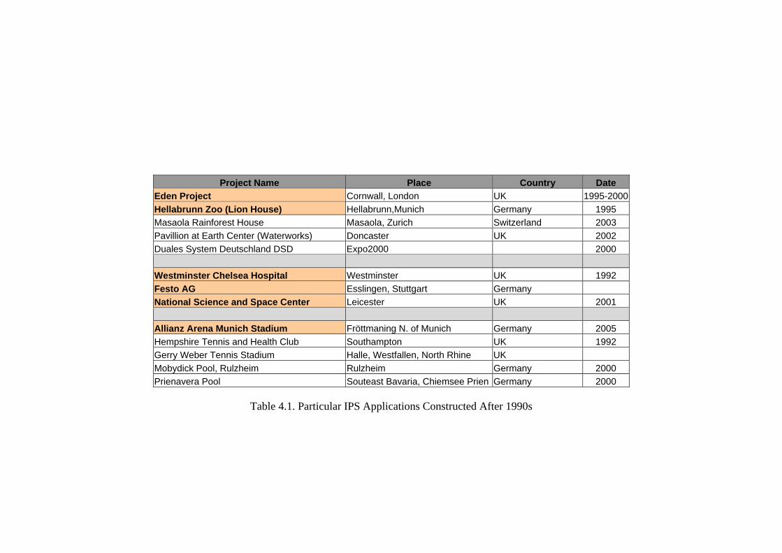
Table 4.1. Particular IPS Applications Constructed After 1990s
Project Name Place Country Date
Eden Project Cornwall, London UK 1995-2000
Hellabrunn Zoo (Lion House) Hellabrunn,Munich Germany 1995
Masaola Rainforest House Masaola, Zurich Switzerland 2003
Pavillion at Earth Center (Waterworks) Doncaster UK 2002
Duales System Deutschland DSD Expo2000 2000
Westminster Chelsea Hospital Westminster UK 1992
Festo AG Esslingen, Stuttgart Germany
National Science and Space Center Leicester UK 2001
Allianz Arena Munich Stadium Fröttmaning N. of Munich Germany 2005
Hempshire Tennis and Health Club Southampton UK 1992
Gerry Weber Tennis Stadium Halle, Westfallen, North Rhine UK
Mobydick Pool, Rulzheim Rulzheim Germany 2000
Prienavera Pool Souteast Bavaria, Chiemsee Prien Germany 2000

1
Appendix A
General film properties of the ETFE foil are classified as below:
Thermoplastic and a fluoropolymer
Isotropic sheeting or a film
Material is not a petrochemical derivative
Water based / not solvent
Density of ETFE Foil is 1.7 - 1.75 g/ cm 3
Melting point of 275° C, although the foil softens below this temperature (200oC)
Resistant to temperature extremes - short time up to 230°C
ETFE Foil is with in the low flammability category B1 when tested to DIN 4102
The presence of Fluorine makes the material self-extinguishing.
ETFE Foil is considered to be Class 0 under UK regulations.
ETFE Foil has an oxygen index (LOI) 35% when tested to ASTM D 2863/77.
ETFE Foil is classified M2 (i.e. no burning drips) according to NF P 92-505.
Highly durable (life span >20 years); it is virtually unaffected by aging
The material is recyclable
Wide service temperature (from -200°C to +150°C )
It does not degrade under Ultra Violet light or atmospheric pollution.
Extremely resistant to dirt and self cleaning property, due to low surface tension
Resistance to tear and penetration
Resistant to hailstone impact
Excellent resistance against UV and weathering
Does not harden, yellow or deteriorate over time
Does not degrade under UV light or atmospheric pollution
Excellent weather stability
Optimal resistance to chemicals
Material is highly elastic
Lightweight, 200m single layer weighs 350g/m2
Sound reduction index of less than 10 dB.
Acoustically soft (triple layer weighs approx. 1 kg/m2)
Good insulation value, depending on the number of layers

2
The foil provides excellent electrical insulation, making it suitable for many
industrial uses.
High degree of light transparency. The foil is transparent (92 - 96%)
The foil is permeable to UV light (UV- A %100, UV-B %50)
High light transmittance from UV- to IR-range
To regulate light permeability, the foil can be supplied printed or white
High tensile strength at break
High elongation range (% 300-400)
High tensile strength (40-50 N/mm2)
High tear strength (400-500 N/mm)
Very smooth surface due to extrusion
Can be printed with graphic patterns
Outstanding separating quality
Excellent weldability
High variety of mechanical film connection possibilities like sewing, nailing,
clamping etc.
Tailor made optimizing of film properties
General Properties of IPS are as shown below:
Lightweight
Flexible
Good environmental and climatic control properties
Cost effective
Energy efficient, minimizing building energy consumption
Ecologically friendly technology
Extremely long lasting, it can be used as the permanent building envelope.
Very low level of embodied energy
Virtually total (architectural) freedom in terms of shape
Low maintenance buildings
Can be manufactured in large sizes
Can span much greater distance than conventional cladding technology
High resistance to environmental attacks
High resistance to bomb blast

3
High resistance to strong winds
High resistance to sand storm
Self venting under fire condition
Maximizing internal comfort
Solar shading can be achieved
High light transmission in multilayer
Can be translucent or printed to limit light and heat gain
The density, color and number of layers can be varied
Outstanding insulation properties (low U-value)
Reduces heat loses due to air infiltration
React to the sun and change their transmission and insulation throughout the day
Reduces need for a heavier load-bearing structure
Reduces need for a heavier foundation
Reduces need for movement joints
Considerably less initial investment cost than the cost of conventional roof
structures
Reduces the life cycle cost (maintenance) to very low levels
Reduces risk in construction
Reduces insurance cost for transportation during construction
Prevent flashover or catastrophic structural collapse of the primary structure
Does not reflect internally generated noise back to the occupants.
Can penetrate the rain sound
Reduces the need for sound suppressors for specific application
Increase harvest and quality in greenhouses.
Minimizes structural shading
Enables suntan, prevents skin diseases

4
Appendix B UV Radiation Energy that is emitted in the form of electromagnetic waves with a wavelength of 1-380nm, which is composed of UV-A, UV-B, and UV-C light; UV-A light being the longest wavelength and having the smallest energy and UV-C light being the shortest wavelength and having the highest energy. All UV-C light and most UV-B light is filtered out of the atmosphere via the ozone layer. However, UV-A light travels to the surface of the earth. Source: [Environmental Pollution; v88n2; 219; 1995.] [Photochemistry and Photobiology; v51n6; 757; 1990.] UV-A Ultraviolet light that has wavelengths of 320nm to 400nm. The wavelengths of this light are shorter than visible light and are not absorbed in the stratosphere by ozone. [Deep Sea Research Part I: Oceanographic Research Papers, v. 48, p. 741-759] Source: Atmospheric Chemistry Glossary UV-B An ultraviolet wavelength of light between 280nm and 320nm whose intensity is increasing at the earth's surface (probably causing increases in skin cancer), This UV increase is because of decreases in stratospheric ozone. [Research and Development Magazine; v39; 18LS; 1997.] [Chemical and Engineering News; v71; 12-13; 1993.] UV-C Light that spans the spectrum with wavelengths of 10nm to 290nm. These wavelengths of ultraviolet light are extremely dangerous to human and animal tissue and is totally absorbed in the stratosphere by ozone and molecular oxygen. Source: [Environmental and Experimental Botany, v. 45, p. 1-9]
UV Radiation Definitions Source: www.webref.com
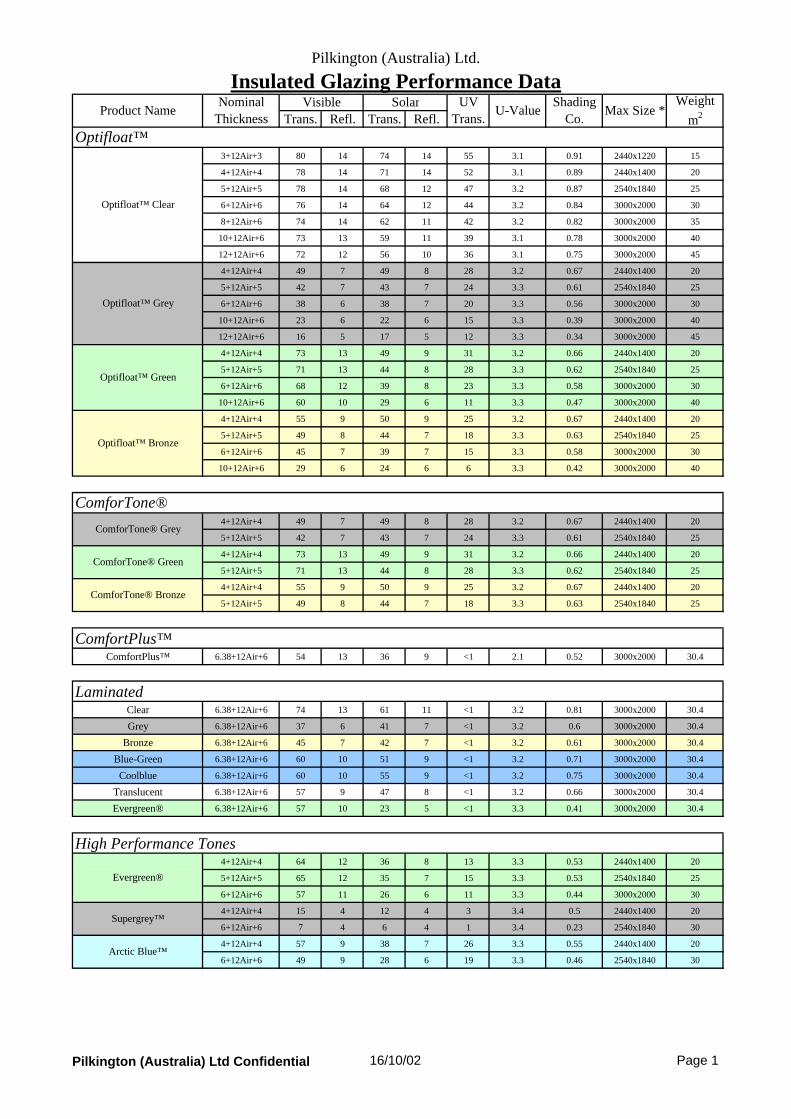
Pilkington (Australia) Ltd.
Insulated Glazing Performance Data
Trans. Refl. Trans. Refl.
3+12Air+3 80 14 74 14 55 3.1 0.91 2440x1220 15
4+12Air+4 78 14 71 14 52 3.1 0.89 2440x1400 20
5+12Air+5 78 14 68 12 47 3.2 0.87 2540x1840 25
6+12Air+6 76 14 64 12 44 3.2 0.84 3000x2000 30
8+12Air+6 74 14 62 11 42 3.2 0.82 3000x2000 35
10+12Air+6 73 13 59 11 39 3.1 0.78 3000x2000 40
12+12Air+6 72 12 56 10 36 3.1 0.75 3000x2000 45
4+12Air+4 49 7 49 8 28 3.2 0.67 2440x1400 20
5+12Air+5 42 7 43 7 24 3.3 0.61 2540x1840 25
6+12Air+6 38 6 38 7 20 3.3 0.56 3000x2000 30
10+12Air+6 23 6 22 6 15 3.3 0.39 3000x2000 40
12+12Air+6 16 5 17 5 12 3.3 0.34 3000x2000 45
4+12Air+4 73 13 49 9 31 3.2 0.66 2440x1400 20
5+12Air+5 71 13 44 8 28 3.3 0.62 2540x1840 25
6+12Air+6 68 12 39 8 23 3.3 0.58 3000x2000 30
10+12Air+6 60 10 29 6 11 3.3 0.47 3000x2000 40
4+12Air+4 55 9 50 9 25 3.2 0.67 2440x1400 20
5+12Air+5 49 8 44 7 18 3.3 0.63 2540x1840 25
6+12Air+6 45 7 39 7 15 3.3 0.58 3000x2000 30
10+12Air+6 29 6 24 6 6 3.3 0.42 3000x2000 40
4+12Air+4 49 7 49 8 28 3.2 0.67 2440x1400 20
5+12Air+5 42 7 43 7 24 3.3 0.61 2540x1840 25
4+12Air+4 73 13 49 9 31 3.2 0.66 2440x1400 20
5+12Air+5 71 13 44 8 28 3.3 0.62 2540x1840 25
4+12Air+4 55 9 50 9 25 3.2 0.67 2440x1400 20
5+12Air+5 49 8 44 7 18 3.3 0.63 2540x1840 25
ComfortPlus™ 6.38+12Air+6 54 13 36 9 <1 2.1 0.52 3000x2000 30.4
Clear 6.38+12Air+6 74 13 61 11 <1 3.2 0.81 3000x2000 30.4
Grey 6.38+12Air+6 37 6 41 7 <1 3.2 0.6 3000x2000 30.4
Bronze 6.38+12Air+6 45 7 42 7 <1 3.2 0.61 3000x2000 30.4
Blue-Green 6.38+12Air+6 60 10 51 9 <1 3.2 0.71 3000x2000 30.4
Coolblue 6.38+12Air+6 60 10 55 9 <1 3.2 0.75 3000x2000 30.4
Translucent 6.38+12Air+6 57 9 47 8 <1 3.2 0.66 3000x2000 30.4
Evergreen® 6.38+12Air+6 57 10 23 5 <1 3.3 0.41 3000x2000 30.4
4+12Air+4 64 12 36 8 13 3.3 0.53 2440x1400 20
5+12Air+5 65 12 35 7 15 3.3 0.53 2540x1840 25
6+12Air+6 57 11 26 6 11 3.3 0.44 3000x2000 30
4+12Air+4 15 4 12 4 3 3.4 0.5 2440x1400 20
6+12Air+6 7 4 6 4 1 3.4 0.23 2540x1840 30
4+12Air+4 57 9 38 7 26 3.3 0.55 2440x1400 20
6+12Air+6 49 9 28 6 19 3.3 0.46 2540x1840 30
ComforTone®
ComforTone® Grey
ComforTone® Green
ComforTone® Bronze
High Performance Tones
Optifloat™ Green
Optifloat™
Solar UV Trans.
U-ValueWeight
m2Max Size *
Optifloat™ Clear
Optifloat™ Grey
Shading Co.
Product Name
Laminated
Evergreen®
Supergrey™
Nominal Thickness
Visible
Optifloat™ Bronze
ComfortPlus™
Arctic Blue™
Pilkington (Australia) Ltd Confidential 16/10/02 Page 1

Pilkington (Australia) Ltd.
Insulated Glazing Performance Data
Trans. Refl. Trans. Refl.
TS21 on Clear 6+12Air+6 19 19 12 20 9 2.9 0.25 3000x2000 30
TS30 on Clear 6+12Air+6 27 16 18 15 14 3.1 0.33 3000x2000 30
SS22 on Clear 6+12Air+6 20 20 12 19 9 2.9 0.26 3000x2000 30
SS08 on Clear 6+12Air+6 7 38 5 33 4 2.7 0.15 3000x2000 30
TS21 on Green 6+12Air+6 17 15 8 12 3 2.9 0.22 3000x2000 30
TS30 on Green 6+12Air+6 26 13 11 10 5 3.1 0.27 3000x2000 30
SS22 on Green 6+12Air+6 17 16 8 12 4 3 0.22 3000x2000 30
TS21 on Grey 6+12Air+6 9 8 7 10 3 2.9 0.22 3000x2000 30
TS30 on Grey 6+12Air+6 13 8 11 9 4 3.1 0.27 3000x2000 30
SS22 on Grey 6+12Air+6 10 9 8 10 3 3 0.23 3000x2000 30
SS22 on Clear 6.38+12Air+6 20 26 15 27 <1 3.2 0.28 3000x2000 30.4
TS30 on Clear 6.38+12Air+6 31 18 21 19 <1 3.3 0.36 3000x2000 30.4
TS21 on Clear 6.38+12Air+6 22 24 14 27 <1 3.2 0.27 3000x2000 30.4
SL20 Grey 6.38+12Air+6 10 10 10 13 <1 3.3 0.25 3000x2000 30.4
SL20 Bronze 6.38+12Air+6 12 13 10 14 <1 3.3 0.25 3000x2000 30.4
SL20 Green 6.38+12Air+6 15 20 12 19 <1 3.3 0.27 3000x2000 30.4
SL20 Coolblue 6.38+12Air+6 15 20 13 21 <1 3.3 0.27 3000x2000 30.4
SL20 Silver 6.38+12Air+6 18 26 14 24 <1 3.3 0.28 3000x2000 30.4
Eclipse Grey (#2) 6+12Air+6 17 14 21 11 3 3.3 0.38 3000x2000 30
Eclipse Bronze (#2) 6+12Air+6 21 19 24 14 3 3.2 0.41 3000x2000 30
Eclipse Blue-Green (#2) 6+12Air+6 30 33 23 17 4 3.2 0.39 3000x2000 30
Eclipse Gold (#2) 6+12Air+6 29 43 26 32 2 3.2 0.4 3000x2000 30
Eclipse Clear (#2) 6+12Air+6 36 42 38 27 8 3.2 0.55 3000x2000 30
Eclipse Evergreen (#2) 6+12Air+6 28 25 15 12 2 3.3 0.31 3000x2000 30
Eclipse Arctic Blue (#2) 6+12Air+6 23 20 16 12 4 3.3 0.33 3000x2000 30
S4 Neutral 8.38+12Air+6 53 12 35 11 <1 2.1 0.51 3000x2000 35.4
S4 Standard 8.38+12Air+6 49 11 24 7 <1 2.2 0.38 3000x2000 35.4
S4 Grey 8.38+12Air+6 32 7 24 7 <1 2.2 0.38 3000x2000 35.4
S4 Green 8.38+12Air+6 44 10 18 6 <1 2.2 0.31 3000x2000 35.4
S4 Blue 8.38+12Air+6 38 10 19 6 <1 2.2 0.32 3000x2000 35.4
E4 Clear 8.76+12Air+6 61 12 41 9 <1 2.1 0.58 3000x2000 35.8
E4 Clear 8.76+12Air+6 61 12 40 9 <1 2.1 0.56 3000x2000 40.8
E6 Clear 12.76+12Air+6 60 12 38 8 <1 2.1 0.54 3000x2000 45.8
E4 Standard 8.76+12Air+6 62 14 33 8 <1 2.1 0.48 3000x2000 35.8
E6 Standard 12.76+12Air+6 60 12 28 6 <1 2.1 0.43 3000x2000 45.8
E4 Grey 8.76+12Air+6 43 8 34 8 <1 2.1 0.5 3000x2000 35.8
E6 Grey 12.76+12Air+6 33 6 27 6 <1 2.1 0.41 3000x2000 45.8
E4 Standard I3 8.76+12Air+6 31 6 21 5 <1 2.1 0.35 3000x2000 35.8
E4 Standard I4 8.76+12Air+6 54 11 35 7 <1 2.1 0.49 3000x2000 35.8
E4 Green 8.76+12Air+6 58 12 27 7 <1 2.1 0.42 3000x2000 35.8
E6 Green 12.76+12Air+6 50 10 19 5 <1 2.1 0.32 3000x2000 45.8
E6 Green I3 12.76+12Air+6 25 5 11 4 <1 2.2 0.24 3000x2000 45.8
Weight m2
Solar UV Trans.
U-ValueShading
Co.Product Name
Nominal Thickness
Visible
SolarE™ Laminates (New S4 Range)
SolarE™ Laminates
Eclipse™ Reflective Glass
Suncool® High Performance - Laminated
Suncool® High Performance Reflective
Max Size *
Pilkington (Australia) Ltd Confidential 16/10/02 Page 2

Pilkington (Australia) Ltd.
Insulated Glazing Performance Data* Units are limited to a maximum of 150kg this may effect the maximum size which can be manufactured.Notes - Pilkington clear float has been used as the backing glassTypical measured values of Pilkington production are provided
The Ultraviolet spectrum is from 300nm to 380nmAll performance data is calculated using LBL window 4.1 software, Ashrae standard summer conditions have
Pilkington (Australia) Ltd Confidential 16/10/02 Page 3

Pilkington (Australia) Ltd.
Single Glazing Performance Data
Trans. Refl. Trans. Refl.
3 89 8 86 8 71 5.9 1 4600x2860 7.5
4 88 8 84 8 67 5.9 0.98 4600x2860 10
5 88 8 82 7 65 5.9 0.97 4600x3120 12.5
6 87 8 80 7 62 5.9 0.95 5100x3120 15
8 85 8 77 7 57 5.8 0.93 5100x3120 20
10 83 7 73 7 54 5.8 0.89 5100x3120 25
12 82 7 70 7 48 5.8 0.87 5100x3120 30
15 80 7 65 7 44 5.8 0.82 4600x3210 37.5
19 78 7 60 6 40 5.8 0.78 4600x3210 47.5
4 55 5 57 5 34 6.3 0.77 4600x2860 10
5 48 5 52 5 30 6.3 0.73 4600x3120 12.5
6 43 5 47 5 25 6.3 0.69 4600x3120 15
10 26 5 27 5 12 6.3 0.52 4600x3120 25
12 18 5 21 5 9 6.3 0.47 4600x3120 30
4 82 8 58 6 37 6.2 0.77 4600x3120 10
5 80 8 53 6 34 6.2 0.73 4600x3120 12.5
6 78 7 49 6 29 6.3 0.7 4600x3120 15
10 69 6 36 5 14 6.3 0.6 4600x3120 25
4 62 6 59 6 30 6.2 0.78 4600x2860 10
5 56 5 54 5 23 6.3 0.75 4600x3120 12.5
6 51 5 49 5 19 6.3 0.7 4600x3120 15
10 33 5 30 5 7 6.3 0.55 4600x3120 25
ComforTone®4 55 5 57 5 34 6.3 0.77 4600x2860 10
5 48 5 52 5 30 6.3 0.73 4600x3120 12.5
4 82 8 58 6 37 6.2 0.77 4600x3120 10
5 80 8 53 6 34 6.2 0.73 4600x3120 12.5
4 62 6 59 6 30 6.2 0.78 4600x2860 10
5 56 5 54 5 23 6.3 0.75 4600x3120 12.5
ComfortPlus™ComfortPlus™ 6.38 62 10 44 8 <1 3.9 0.61 3300x2440 15.4
Laminated6.38 89 7 77 7 <1 5.9 0.92 3660x2440 15.4
6.76 88 7 75 7 <1 6 0.9 3660x2440 15.8
7.52 88 7 74 6 <1 6 0.89 3660x2440 16.6
Grey 6.38 44 5 47 5 <1 6.1 0.67 3660x2440 15.4
Bronze 6.38 52 6 54 5 <1 6.1 0.72 3660x2440 15.4
Blue-Green 6.38 73 6 68 6 <1 6 0.84 3660x2440 15.4
Coolblue 6.38 76 6 73 5 <1 6 0.88 3660x2440 15.4
Translucent 6.38 65 6 58 6 <1 6 0.76 3660x2440 15.4
Evergreen® 6.38 66 6 29 5 <1 6.2 0.55 3660x2440 15.4
Shading Co.
Weight m2
Clear
Optifloat™ Clear
Optifloat™ Grey
Optifloat™ Green
ComforTone® Grey
ComforTone® Green
ComforTone® Bronze
Optifloat™ Bronze
Nominal Thickness
Visible Solar
Optifloat™
Max SizeProduct NameUV
TransU-Value
Pilkington (Australia) Ltd Confidential 16/10/02 Page 1

Pilkington (Australia) Ltd.
Single Glazing Performance Data
Trans. Refl. Trans. Refl.
4 73 8 43 6 16 6.3 0.66 4600x3120 10
5 73 8 43 6 19 6.3 0.66 4600x3120 12.5
6 65 8 33 6 13 6.3 0.58 4600x3120 15
4 17 4 14 4 4 6.5 0.44 5100x3300 10
6 8 4 8 4 1 6.5 0.39 5100x3300 15
4 64 6 45 5 31 6.3 0.69 5080x3150 10
6 56 6 35 5 23 6.3 0.6 5080x3150 15
TS21 on Clear 6 21 19 15 20 12 5.3 0.36 3660x2140 15
TS30 on Clear 6 30 15 22 15 15 5.6 0.44 3660x2140 15
SS22 on Clear 6 22 20 15 19 12 5.4 0.36 3660x2140 15
SS08 on Clear 6 8 38 6 33 6 5 0.23 3660x2140 15
TS21 on Green 6 18 17 10 12 4 5.3 0.34 3660x2140 15
TS30 on Green 6 27 12 14 10 6 5.6 0.39 3660x2140 15
SS22 on Green 6 19 16 10 12 5 5.8 0.34 3660x2140 15
TS21 on Grey 6 10 8 9 10 3 5.3 0.34 3660x2140 15
TS30 on Grey 6 16 8 14 9 5 5.6 0.4 3660x2140 15
SS22 on Grey 6 11 9 10 10 4 5.4 0.34 3660x2140 15
Suncool® High Performance - LaminatedSS22 on Clear 6.38 23 26 18 27 <1 6.15 0.40 3660x2140 15.4
TS30 on Clear 6.38 35 17 26 19 <1 6.15 0.48 3660x2140 15.4
TS21 on Clear 6.38 25 23 17 27 <1 6.15 0.39 3660x2140 15.4
SL20 Grey 6.38 11 10 12 13 <1 6.5 0.38 3660x2140 15.4
SL20 Bronze 6.38 13 13 12 14 <1 6.5 0.38 3660x2140 15.4
SL20 Green 6.38 17 20 15 19 <1 6.4 0.38 3660x2140 15.4
SL20 Coolblue 6.38 13 20 16 21 <1 6.4 0.38 3660x2140 15.4
SL20 Silver 6.38 20 26 17 24 <1 6.4 0.38 3660x2140 15.4
Eclipse Grey (#2) 6 19 14 27 10 4 6.2 0.52 3302x2438 15
Eclipse Bronze (#2) 6 23 19 31 13 4 6.2 0.54 3302x2438 15
Eclipse Blue-Green (#2) 6 33 32 28 16 6 6.2 0.51 3302x2438 15
Eclipse Gold (#2) 6 31 42 33 31 2 6.1 0.5 3302x2438 15
Eclipse Clear (#2) 6 39 40 49 25 11 6.2 0.65 3302x2438 15
Eclipse Evergreen (#2) 6 30 24 18 11 3 6.4 0.44 3302x2438 15
Eclipse Arctic Blue (#2) 6 25 19 20 11 5 6.4 0.46 3302x2438 15
4 82 11 68 11 56 3.6 0.83 5100x3210 10
6 82 10 65 10 49 3.6 0.81 5100x3210 15
Max Size
SuperGrey™
Arctic Blue™
Visible Solar UV Trans
Weight m2
Nominal Thickness
Shading Co.
Pilkington Energy Advantage™
U-Value
Evergreen®
Product Name
High Performance Tones
Suncool® High Performance Reflective
Eclipse™ Reflective Glass
Low E Glass
Pilkington (Australia) Ltd Confidential 16/10/02 Page 2
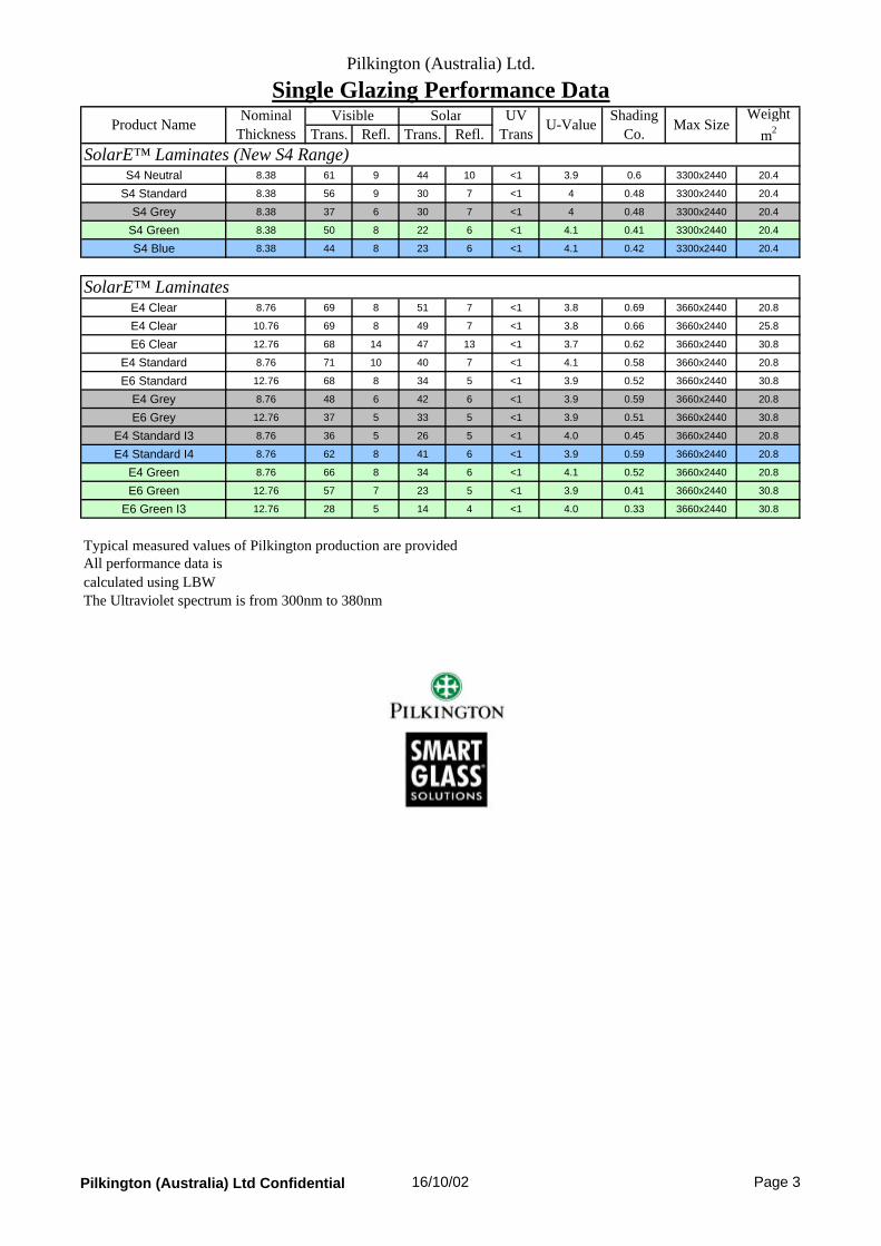
Pilkington (Australia) Ltd.
Single Glazing Performance Data
Trans. Refl. Trans. Refl.
S4 Neutral 8.38 61 9 44 10 <1 3.9 0.6 3300x2440 20.4
S4 Standard 8.38 56 9 30 7 <1 4 0.48 3300x2440 20.4
S4 Grey 8.38 37 6 30 7 <1 4 0.48 3300x2440 20.4
S4 Green 8.38 50 8 22 6 <1 4.1 0.41 3300x2440 20.4
S4 Blue 8.38 44 8 23 6 <1 4.1 0.42 3300x2440 20.4
E4 Clear 8.76 69 8 51 7 <1 3.8 0.69 3660x2440 20.8
E4 Clear 10.76 69 8 49 7 <1 3.8 0.66 3660x2440 25.8
E6 Clear 12.76 68 14 47 13 <1 3.7 0.62 3660x2440 30.8
E4 Standard 8.76 71 10 40 7 <1 4.1 0.58 3660x2440 20.8
E6 Standard 12.76 68 8 34 5 <1 3.9 0.52 3660x2440 30.8
E4 Grey 8.76 48 6 42 6 <1 3.9 0.59 3660x2440 20.8
E6 Grey 12.76 37 5 33 5 <1 3.9 0.51 3660x2440 30.8
E4 Standard I3 8.76 36 5 26 5 <1 4.0 0.45 3660x2440 20.8
E4 Standard I4 8.76 62 8 41 6 <1 3.9 0.59 3660x2440 20.8
E4 Green 8.76 66 8 34 6 <1 4.1 0.52 3660x2440 20.8
E6 Green 12.76 57 7 23 5 <1 3.9 0.41 3660x2440 30.8
E6 Green I3 12.76 28 5 14 4 <1 4.0 0.33 3660x2440 30.8
Typical measured values of Pilkington production are providedAll performance data is calculated using LBW The Ultraviolet spectrum is from 300nm to 380nm
Weight m2
Solar UV Trans
U-ValueProduct NameNominal
ThicknessShading
Co.SolarE™ Laminates (New S4 Range)
SolarE™ Laminates
VisibleMax Size
Pilkington (Australia) Ltd Confidential 16/10/02 Page 3

Appendix D
Membrane Materials Property Chart Source: Moritz, 2000/6

1
TEXLON AG. ........................................................................................................................... Nadir Polat Hirsernriedstrasse CH - 6074 Giswil Tel. ++41 41 6752277 Fax ++41 41 6752434 [email protected] VECTOR SPECIAL PROJECTS LTD .................................................................................. Ben Morris Studio 4 The Cooperage 91 Brick Lane London E1 6QL t +44 (0) 20 7375 2756 f +44 (0) 20 7375 2759 [email protected] www.vector-foiltec.com FOILTEC GMBH Steinacker 3, D-28717, Bremen Germany t +49 421 69351 0 f +49 421 69351 19 [email protected] www.foiltec.de FOILTEC NA 13 Green Mountain Drive, Cohoes, New York 12047 t +1 518 783 0575 f +1 518 783 0474 [email protected] www.foiltecna.com NOWOFOL Kunststoffprodukte GmbH & Co. KG D-83310 Po box 1263, Siegsdorf-Germany telefon: +49 (0) 8662/6602-0 telefax: +49 (0) 8662/6602-50. www.nowofol.de [email protected] PFEIFER Seil und Hebetechnik GmbH Service-Center Berlin Holzhauser Strasse 140h, 13509 Berlin phone 030-9120030 fax 030-91200322 [email protected] SKYSPAN (EUROPE) GmbH ........................................................................................... Anette Lutzeier Nordstrasse 10, D-83253 Rimsting, Germany Tel: +49 (0)8051 6888-0 Fax: +49 (0)8051 6888-118 [email protected] http://www.skyspan.com SKYSPAN (UK) LIMITED The Portway Centre, Old Sarum, Salisbury, Wiltshire SP4 6EB, UK Tel: +44 (0)1722 331599 Fax: +44 (0)1722 415922 [email protected] BIRDAIR, INC. 65 Lawrence Bell Drive Amherst, New York 14221USA Phone: +1 800.622.2246 [email protected]

2
BIRDAIR EUROPE STROMEYER GmbH ........................................................... Mr. Joob Groenveld Marlene-Dietrich-Str. 5 D-89231 Neu Ulm Germany Phone: ++49 (0) 731 98588765 Fax: ++49 (0) 731 98588769 www.birdair.de ENSINGER GmbH Headquarter and European stock ................ Mr. Klaus Ensinger & Dr. Roland Reber Rudolf-Diesel-Str. 8, 71154 Nufringen........................................................Bjoern Uehlken – Peter Bongart Telefon +49 (0) 7032 819-0 Fax +49 (0) 7032 819-100 [email protected] KOCH HIGHTEX GmbH. Nordstraße 1, 83253 Rimsting/ChiemseeGermany +49 8051 69090 +49 8051 690919 http://www.kochmembranen.de/ [email protected] DYNEON GmbH & Co. KG .......................................................................................... Mr. Helmut Frisch Werk Kelsterbach D-65444 Kelsterbach Germany Phone: ++49 (0) 6107 772 5080 Fax: ++49 (0) 6107 772 5093 www.dyneon.com DUPONT UK Ltd. ............................................................................................................. Mr. Ian Fletcher Maylands Avenue, Hemel Hempstead Hertfordshire HP2 7DP Great Britain Phone: ++44 (0) 1442 346704 Fax: ++44 (0) 1442 218575 www.teflon.com [email protected] FERRARI S. A. ............................................................................................................... Mr. Tim Schubert B.P. 54 F-38352 La Tour-du-Pin, Cedex France Phone: ++33 (0) 474971091 Fax: ++33 (0) 4 74976720 www.ferrari-textiles.com JULIUS HEYWINKEL GmbH Textil- und Kunststoffwerk .............................. Mr. Hartwig Birszwilks Heywinkelstraße 1 D-49565 Bramsche Germany Phone: ++49 (0) 5468 778 500 Fax: ++49 (0) 5468 778 319 [email protected] www.heytex.de VERSEIDAG-INDUTEX GmbH ................................................................................. Mr. Albert Driesch Industriestrasse 56 D-47803 Krefeld Germany Phone: ++49 (0) 2151 876200 Fax: ++49 (0) 2151 876291 www.vsindutex.de CANOBBIO S.p.A ................................................................................................. Mr. Federico Canobbio Via Roma 3, I-15053 Castelnuovo Scrivia (AL) Italy Phone: ++39 (0) 1 31823353 Fax: ++39 (0) 1 31823521 www.canobbio.com

3
MESSE FRANKFURT GmbH ................................................................................. Mr. Michael Jänecke Ludwig-Erhard-Anlage 1 D-60327 Frankfurt Germany Phone: ++49 (0) 69 7575 or 6710 Fax: ++49 (0) 69 7575 6541 www.techtextil.com [email protected] SAINT-GOBAIN PERFORMANCE PLASTICS Advanced film & plastics - Europe Clonroad - Ennis County Clare, Ireland t 353 65 68 20 988 f 353 65 68 20 993 www.saintgobain.com ASAHI GLASS Ltd. _AG fluorpolymers www.fluon.com BUITINK TECHNOLOGY Ltd. Nieuwgraff 210 6921RR Duiven, Netherland t 026 31 94181 f 026 3194191 [email protected] www.buitink-technology.com COVERTEX GmbH. Berghammer Strasse 19 83119 Obing T 0 8624 8969-0 F 0 8624 8969-20 www.covertex.de [email protected] GRIMSHAW And Partners Architectural Office .................................................................. Eliza Sharp 1 Conway Street Fitzroy Square London WIT 6LR t +44 0 20 72 91 4103 f +44 0 20 72 91 4194 www.grimshaw-architects.com BURO HAPPOLD ................................................................................................. Syreeta Robinson-Gayle Camden Mill, Lower Bristol road, Bath BA2 3DQ ENGLAND t 01 225 337 510 www.burohappold.com