
INDIAN NOTICES TO MARINERS - WELCOME TO NHO Edition 2012.pdf · Indian Notices to Mariners are...
206
-
Upload
nguyenkhanh -
Category
Documents
-
view
258 -
download
2
Transcript of INDIAN NOTICES TO MARINERS - WELCOME TO NHO Edition 2012.pdf · Indian Notices to Mariners are...

INDIAN NOTICES TO MARINERS
SPECIAL EDITION – 2012
RECORD OF CORRECTIONS The inclusion of corrections in this volume should be recorded in the following table:-
Notices to Mariners
2012 _____________________________________________________________________________________________________________________________________________________________________________________________________________________________________________________________________________________________________________________________________________________________________________________________________________________________________________________________________________________________________________________________________________________________________________________________________________________________________________________
2013
_____________________________________________________________________________________________________________________________________________________________________________________________________________________________________________________________________________________________________________________________________________________________________________________________________________________________________________________________________________________________________________________________________________________________________________________________________________________________________________________
2014
___________________________________________________________________________________________________________________________________________________________________________________________________________________________________________________________________________________________________________________________________________________________________________________________________________________________________________________________________________________________________________________________________________________________________________________________________________________ _________________ _________________
2015
_____________________________________________________________________________________________________________________________________________________________________________________________________________________________________________________________________________________________________________________________________________________________________________________________________________________________________________________________________________________________________________________________________________________________________________________________________________________________________________________

INDIAN
NOTICES TO MARINERS
SPECIAL EDITION
2012
NATIONAL HYDROGRAPHIC OFFICE DEHRA DUN

INDIAN
NOTICES TO MARINERS
SPECIAL EDITION 2012
CONTAINING SPECIAL NOTICES 1-28
NOTE In addition to fortnightly editions of Notice to Mariners, following editions are also published by Indian National Hydrographic office (a) Annual Edition – List of up-to-date corrections to Navigational Charts, Unexploded Charges and Text of Temporary and Preliminary Notices will be published annually as Annual Edition to Indian Notice to Mariners.
(b) Special Edition - Notices published in this Edition are of permanent nature. Any amendment/addition to these Notices shall be issued through Fortnightly Indian Notices to Mariners. Mariners are therefore advised to “RETAIN THIS EDITION” till its supersession/cancellation by this office. (c) Indian Notices to Mariners Special Edition 2008 is hereby cancelled and should be destroyed.

PREFACE
This fifth edition of the Indian Notices to Mariners, Special Edition contains Special Notices to Mariners 1 to 28 which are of permanent nature. This edition contains the latest information received at the National Hydrographic Office, Dehradun till date. Copies of this publication can be obtained from authorised agents for the sale of Indian charts. The National Hydrographic Office maintains updated navigational charts of the Indian subcontinent and adjacent areas and associated nautical publications. Mariners and concerned authorities are requested to inform this office of any changes affecting these permanent notices. Observations and suggestions can be sent to this office through the official website www.hydrobharat.nic.in or email at [email protected] & [email protected]. Information received and assessed will be included in the Indian Notices to Mariners. This edition supersedes the fourth edition (2008), which is cancelled.
(SK Jha) Rear Admiral Chief Hydrographer to the Government of India

INDEX
Special Notice No. Subject Page No.
1. General notice 1
2. Availability of Notices to Mariners 1
3. Reliance on charts and predicted tides 2
3A. Reliance on the use of ENC and ECDIS system 3
4. Caution when approaching to Indian ports/entry into restricted areas 5
5. Weather bulletins issued to ships by the Indian Meteorological Department 9
6. Warning to ports and storm signal stations 18
7. Distress and rescue at sea-ships and aircraft 21
8. The Indian ship position and information reporting system (INSPIRES) 67
9. Firing practice and firing exercise areas, danger areas 101
10. Caution with regards to ships approaching squadrons etc. 116
11. Information concerning submarines 118
12. Radio navigational warnings 127
13. Submarine cables 136
14. Indian merchant ships - use of radar in time of emergency or war 138
15. Instructions regarding rendering reports of shoals obtained by echo sounding 139
16. National data buoy programme 143
17. Significance of good seamanship and safe navigational watch keeping practices 150
18. International Hydrographic Organization 151
19. Information about radar beacons 155
20. Development of offshore oil and gas fields 157
21. Traffic separation scheme-ships routeing 160
22. IALA maritime buoyage system 165
23. Former mine danger areas; swept routes and instructions regarding 174
explosives picked up at sea.
24. Notices to Mariners - explanation of terms 176
25. National claims to maritime jurisdiction 177
26. Satellite navigation systems 183
27. Indian DGPS beacons network 196
28. List of depots and chart agents for the sale of Indian charts and other 197
hydrographic publication

1
SPECIAL EDITION OF NOTICES TO MARINERS 2012
Special Notice No. 1: GENERAL NOTICE Mariners, ship owners, port authorities, E&P operators, ship managers, agents and insurance companies are advised to study this Special Notices to Mariners which contain important information pertaining to navigation. Special Notice No. 2: AVAILABILITY OF NOTICES TO MARINERS. 1. Indian Notices to Mariners are published fortnightly on 01st and 16th of every month and are available on website www.hydrobharat.nic.in and with the under-mentioned authorities/organisations.
(The following letters indicate the authorities/organizations at ports/locations to be consulted for Indian N to M) A - Officer-in-Charge, Naval Chart Depot. B - Chart Agents. C - Mercantile Marine Department/State Maritime Board. D - Director General Lighthouses and Lightships. E - Port Officer/Port Conservator/Harbour Master/Shipping Master. F - Deputy Director Fishery Survey of India. G - Director of Hydrographic Service. H - The Ministry of Transport.
INDIAN PORTS/LOCATIONS
Port/Location Symbols Port/Location Symbols Port/Location Symbols Kolkata (Calcutta) E Karwar E Mangalore E Chennai (Madras) B,C,D Kavaratti E Mumbai (Bombay) A,B,E Kochi (Cochin) E Tuticorin E Mormugao (Marmagao) E New Delhi B,D Paradip E Port Blair D,E,F Vishakhapatnam A,B,E Gujarat D
FOREIGN PORTS/LOCATION Port/Location Symbols Port/Location Symbols Port/Location Symbols Myanmar Yangoon
G Kenya Mombasa
E Seychelles Victoria
G
Maldives Island Male
H United kingdom Taunton
G Tanzania Dar-Es-Salam
E
Mauritius Port Louis
E Monaco Monte Carlo
G Srilanka Colombo
E
For details of subscription of Indian Notices to Mariners refer to www.hydrobharat.nic.in at the following link: www.hydrobharat.nic.in/publication_price_list.htm
2
Special Notice No. 3: RELIANCE ON CHARTS AND PREDICTED TIDES. 1. Prudent mariners navigate with adequate under-keel clearance at all times, making due allowances for all the factors that are likely to reduce the depth beneath their keels. Mariners shall use a vessel’s deepest draught when calculating the underkeel allowance. Underkeel allowance means the minimum clearance available between the deepest point on the vessel and the bottom, in still waters. Mariners shall apply a plus or minus allowance for the tide. Mariners calculate their vessel's deepest navigational draught and the controlling depth of the intended transit, including consideration of the following:- (a) The vessel's mean draught; (b) The vessel's trim and list characteristics; (c) The intended transit speed and the corresponding squat characteristics; (d) The tide and current conditions; (e) Present sea state conditions; (f) Past weather impact on water depth; (g) The depth at the facility or anchorage; and (h) The depth of the transit area. To ensure an adequate under-keel clearance throughout a passage, an under-keel allowance may be laid down by competent authority or determined onboard when planning the passage. The factors to be taken into account when determining this allowance are given in "The Mariner's Handbook" (BA NP 100) in detail. 2. However, it is becoming increasingly apparent that economic pressures are causing mariners to navigate through certain areas using an inadequate under-keel allowance. Attention is therefore drawn in particular to the limitations of Hydrographic Surveys and tidal predictions in offshore areas. 3. Hydrographic Surveys have inherent technical limitations. Furthermore, in some dynamic areas the physical conditions and hence the depth of the sea-bed is constantly changing. Nautical charts can therefore seldom, be absolutely reliable in their representation of depth and when tidal predictions are applied to charted depths as if they were actual tidal levels the uncertainties are clearly compounded. 4. The limitations of Hydrographic Surveys are discussed at length in "The Mariner’s Handbook" (BA NP 100) and factors affecting predicted tide levels are described in the introduction to Indian Tide Tables. 5. The frequency and amplitude of negative storm surges, which should also be taken into account, are described in "The Mariner's Handbook" (BA NP 100). 6. Mariners, therefore, should allow for navigational uncertainties by preserving adequate clearances, both horizontally and vertically.

3
Special Notice No. 3A: RELIANCE ON THE USE OF ENC AND ECDIS SYSTEM 1. The electronic chart and associated systems represents an entirely new approach to marine navigation. Such a system is no longer regarded as simply a computer generated display on a monitor designed to replace paper charts. An Electronic Navigation Chart (ENC) and Electronic Chart Display Information System (ECDIS) are real-time navigation concepts that integrate electronic chart data with various types of positioning and navigation systems, including Global Positioning Systems (GPS), Radar/Automatic Radar Plotting Aids (ARPA) and shipboard Automated Identification System (AIS) - an integrated, total bridge navigation system. In 1987, the Harmonisation Group of IMO/IHO was established to develop a performance standard for ECDIS. It was perceived then, that ECDIS would be recognised as a legal equivalent to the folio of paper charts that were required to be carried on ships in accordance with the Safety of Life at Sea (SOLAS) Convention, namely, that it may be used instead of the paper charts. ECDIS, as an automated decision-making aid is capable of continuously determining a vessel’s position in relation to the adjacent land, charted objects, unseen hazards, other vessels in the vicinity and the prevailing marine environment. 2. An electronic navigational chart (ENC) is an official database created by a national hydrographic office for use with an Electronic Chart Display and Information System (ECDIS). An electronic chart must conform to standards stated in the International Hydrographic Organization (IHO) Special Publication S-57 before it can be certified as an ENC. An Electronic Chart Display and Information System (ECDIS) is a computer-based navigation information system that complies with International Maritime Organization (IMO) regulations and can be used as an alternative to paper nautical charts. IMO refers to similar systems not meeting the regulations as Electronic Chart Systems (ECS). An ECDIS system displays the information from electronic navigational charts (ENC) or Digital Nautical Charts (DNC) and integrates position information from the Global Positioning System (GPS) and other navigational sensors, such as radar and automatic identification systems (AIS). 3. On a number of occasions chart data, particularly in canals, locks, harbours, ports and alongside wharves could not withstand the resolution of the ECDIS ‘zooming’ function. In many instances, the result has been that the ship’s image on an ECDIS display is depicted as overlapping the dock or jetty. There are many contributing factors that may suggest that the ship’s image on the ECDIS screen is portrayed where ‘it does not belong’. These are due to GPS errors; DGPS errors; ECDIS errors; Installation errors; ENC conversion errors; chart errors; and hydrographic survey errors. There is also the factor of human-induced error. Error due to GPS and DGPS is not infallible and it is entirely possible for large errors caused by an 'unhealthy ' satellite. Use of ECDIS - Anomalous behaviour in some systems. 4. Examples of an anomalous display and alarm behaviour have been noted in some ECDIS. Some of this anomalous behaviour appears to relate to software implementation issues, especially in early ECDIS models. 5. In addition to reminding mariners not to rely solely on the automated checks and alarms for dangers provided by ECDIS during route planning and voyage monitoring, there is a need to maintain ECDIS software to ensure any limitations in operational capability. It is recommended that appropriate checks are made with equipment manufacturers, especially where the ENC display is the only source of chart information available. 6. Examples of anomalous behaviour.
(a) A very small proportion of shoal soundings, especially those marked as “reported” on paper charts, are not visible when operating in the default base or standard display modes and do not trigger automatic grounding alarms in route checking or monitoring modes. Most ENC producers have now amended the way in which these particular shoal soundings have been encoded in S57 to resolve this issue.
(b) Some ECDIS may not activate alarms for all land areas shown on ENCs, even where these are surrounded by a shoal depth contour. Whilst land areas such as islands are generally clearly identifiable on ECDIS, in some display configurations small islands can be difficult to see as they may be obscured by other detail such as contour labels. This is most likely to be a problem where only very small scale (usage

4
band 1 and 2) ENCs are available. There are many oceanic areas for which the largest scale chart (both paper and ENC) issued is 1:3.5 million.
(c) It has been noted that on some ECDIS some underwater obstruction hazards only display in ‘full / other’ display mode rather than in default standard mode as might be expected.
The observed anomalies reinforce the need for the continued application of established navigation principles and skills including the need to avoid over-reliance on a single system. Mariners should always undertake careful visual inspection of the entire planned route using the ‘other / all’ display mode to confirm that it, and any deviations from it, is clear of dangers. 7. The text of NAVAREA VIII Warnings issued is as follows:-
(a) NAVAREA VIII – 683/10
“As previously notified by NAVAREA warning, mariners using ECDIS are reminded not to rely solely on automated voyage planning and monitoring checks and alarms. Some ECDIS appear only to undertake route check functions on larger scale ENCs and therefore alarms might not activate. This may not be clearly indicated on the ECDIS display. Mariners should always undertake careful visual inspection of the entire planned route using the ‘other / all’ display mode to confirm that it, and any deviations from it, is clear of dangers.
Recent preliminary investigation indicates that some ECDIS may not display certain combinations of chart features and attributes correctly and on rare occasions may fail to display a navigationally significant feature. This appears to be caused by anomalous behaviour in some ECDIS software, especially early versions. The existence of such anomalies highlights the importance of maintaining ECDIS software to ensure that operational capability and reliability are maintained. It is recommended that appropriate checks are made with the equipment manufacturer. This is of particular importance where ECDIS is the only source of chart information available to the mariner
The International Hydrographic Organization (IHO) is investigating these matters in consultation with ECDIS equipment manufacturers. Further information will be made available through Notices to Mariners and the README.TXT file included on ENC service media.”
(b) NAVAREA VIII – 141/12 “Display anomalies in some ECDIS (.) Mariners are advised that the international hydrographic organization (IHO) check data set shows that some ECDIS systems fail to display some significant underwater features in the standard display mode (.) The use of this check data set, issued through enc service providers and available from the IHO website www.iho.int, to check the operation of ECDIS is strongly recommended (.) JRC has confirmed that certain versions of JRCECDIS fail to display some types of wreck and obstructions, including stranded wrecks, in any display mode (.) Where JRCECDIS is in use, paper charts should be the primary means of navigation until the ECDIS has been proved to operate correctly (.) See www.jrc.co.jp/eng/product/marine/whatsnew/20120313/index.html for further information”
5
Special Notice No. 4: CAUTION WHEN APPROACHING INDIAN PORTS/ENTRY INTO RESTRICTED AREAS Source: Director General of Shipping (Govt. of India, IHQ MoD (Navy).
Closing of Ports; Stopping Movements in Ports 1. The Government of India, having taken into consideration the fact that it may be necessary to forbid entrances to certain ports under their control for reasons of security, is to give notice that on approaching the shores of India or any Indian port or locality, a sharp look out should be kept for the signals described in the following paragraphs, and for the vessels mentioned in Part II, paragraph 9 of this Notice and distinguishing other check signals made by them. In the event of such signals, being displayed, the port or locality should be approached with great caution, as it may be apprehended or obstructions may exist. 2. If entrance to a port is prohibited, three all round visible red flashing lights vertically disposed by night, or three red balls vertically disposed by day, will be exhibited in some conspicuous position in or near its approach. These signals will also be shown by the vessels indicated in Part II of this Notice. 3. If these signals are displayed, vessels must approach the port or locality with greatest caution and implicitly obey all orders and signals given to them by the Examination Vessel, Traffic Control Vessel or Signal Station. 4. If movement of shipping in a port or anchorage, under Naval control is prohibited, three lights red-green-red vertically disposed by night, or a blue flag by day, will be exhibited. Signals affecting movement of shipping in parts of a port will be found in the Public Traffic Regulations for that port. 5. At some ports or localities, search-lights are occasionally exhibited for exercise. 6. Instructions have been given to avoid directing movable search-lights during practice on to vessels under way. However mariners are warned that great care should be taken to keep a sharp lookout for the signal indicated in paragraph 2 above, when search-light are observed to be working. 7. Vessels are particularly warned not to enter "Dangerous Area" or approaches boom defences without permission, not to anchor or remain stopped in a "Dangerous Area" or "Prohibited anchorages" unless specially instructed to do so. Examination Service 8. In certain circumstances, it is also necessary to take special measures to examine individual vessels desiring to enter ports and localities and to control entry in general. This is the task carried out by the Examination Service. Where traffic control vessels act as Examination Vessel, their authority will be the same. 9. In such cases, vessel carrying the distinguishing flags or lights mentioned in paragraph 12 below will be charged with the duty of examining the ships which desire to enter the port and allotting berths in which they shall anchor. If Government vessels, or vessel belonging to the local port authority, are found patrolling in the offing, merchant vessels are advised to communicate with such vessels with a view to obtain information as to the course on which they should approach the port. Such communication will not be necessary if the pilot onboard has already received this information from the local authorities. 10. As the institution of the Examination Service will probably be unknown to vessels desiring to enter the port, special care should be taken in approaching the port, by day and night, to keep a sharp lookout for any vessel carrying the flags or lights mentioned in paragraph 11 to 15 and to be ready to "bring to" at once when hailed by her or warned by the firing of a gun or sound rocket. 11. By day the distinguishing flag of the Examination Vessel or Traffic Control Vessel will be a special flag, white and red horizontal stripes surrounded by a blue border. The vessel would also display three red balls, vertically disposed, if entrance is prohibited.

6
12. Usually the Examination Vessels or Traffic Control Vessels will fly the Blue Ensign, but in certain circumstances they may fly the White Ensign. 13. By night the vessel will carry:- (a) Three red flashing lights, visible all round vertically disposed, if entrance is prohibited. (b) Three green lights, visible all round vertically disposed, if entrance is permitted.
By Day
Special Flag Three Red Balls
Entrance Permitted
Entrance Prohibited
By Night
Three Green Lights Three Flashing Red Lights
Day and Night Visual Signals Hoisted by Examination Vessel
14. The above lights will be carried in addition to the ordinary navigation light, and will show an unbroken light around the horizon. Note: - In some ports, pilot's launch may be used as the Examination Vessel. Masters are to keep sharp lookout for such a launch. 15. Merchant vessels approaching an Indian Port at which the Examination Service is in force, must hoist their signal letters on arriving within visual signal distance of the port, and are not to wait for the signal "What is the name of your vessel?" to be made from the Examination Vessel or Traffic Control Vessel. 16. Masters are warned that, before attempting to enter any port when the Examination Service is in force, they must in their own interest strictly obey all instructions given to them by the Examination Vessel. 17. Whilst at anchor in the Examination Anchorage, Masters are warned that it is forbidden, except for the purpose of avoiding accident, to do any of the following things, without permission from the Examination Officer:- (a) To lower any boat. (b) To communicate with the shore or with other ships. (c) To move the ship. (d) To work cables.

7
(e) To allow any person or thing to leave the ship. (f) To switch on or show any light when black out restrictions are in force. 18. The permission of the Immigration Officer must be obtained before any passenger or member of the crew who has embarked outside India is allowed to land. 19. In case of fog, Masters are enjoined to use the utmost care, and the port should be approached with caution. 20. When the Examination Service is in force, merchant vessels, when approaching ports, are especially cautioned against making use of private signals of any description, either by day or by night; their use will render a vessel liable to be fired on. 21. The pilots attached to the ports will be acquainted with the regulations to be followed. 22. Limits of Examination Anchorages at Okha, Porbandar, Mumbai, Goa, Kochi, Chennai, Visakhapatnam, Gangavaram, Paradip, Kolkata and Port Blair are as follows:-
(a) Okha: - Area enclosed by the following positions:- (i) 220 30'.40 N, 690 02’.00 E (ii) 220 31'.30 N, 690 03’.65 E.
(ii) 220 30’.40 N, 690 03'.65 E. (iv) 220 31’.30 N, 690 02'.00 E.
(b) Porbandar: - Area enclosed by the following positions:- (i) 210 37'.50 N, 690 32'.80 E. (iii) 210 37’.60 N, 690 34'.47 E.
(ii) 210 36'.55 N, 690 34’.05 E. (iv) 210 38’.58 N, 690 33’.30 E.
(c) Mumbai: - Area enclosed by the following positions:-
(i) 180 53'.05 N, 720 49'.83 E. (iii) 180 51'.20 N, 720 49'.63 E.
(ii) 180 51'.55 N, 720 48'.92 E. (iv) 180 52'.40 N, 720 50'.40 E.
(d) Goa: - Area enclosed by the following positions:- (i) 150 23'.56 N, 73043'.96 E (iii) 150 22'.56 N, 73044'.96 E.
(ii) 150 23'.56 N, 730 44'.96 E. (iv) 150 22'.56 N, 730 43'.96 E.
(e) Kochi: - Area enclosed by the following positions:- (i) 90 55'.10 N, 760 08'.60 E (iii) 90 54'.10 N, 760 09'.60 E.
(ii) 90 55'.10 N, 760 09'.60 E. (iv) 90 54'.10 N, 760 08'.60 E.
(f) Chennai: - Area enclosed by the following positions:- (i) 130 09'.00 N, 800 19'.42 E (iii) 130 07'.25 N, 800 21'.09 E. (v) 130 07'.53 N, 800 19'.17 E.
(ii) 130 09'.00 N, 800 21'.42 E. (iv) 130 07'.25 N, 800 19'.42 E.
(g) Vishakhapatnam: - Area enclosed by the following positions:- (i) 170 42'.30 N, 830 19'.70 E (iii) 170 41'.52 N, 830 20'.10 E.
(ii) 170 42'.30 N, 830 21'.00 E. (iv) 170 41'.52 N, 830 20'.65 E.
(h) Gangavaram:- Enclosed by an area of radius 3.4 cable centred on 170 36 '.58 N, 830 16'.00 E (j) Paradip:- Enclosed by an area of radius 5 cable centred on 200 13 '.00 N, 860 41'.00 E (k) Kolkata: - Area enclosed by the following positions:- (i) 210 37'.45 N, 880 00'.70 E (iii) 210 40'.00 N, 880 00'.12 E.
(ii) 210 37'.21 N, 880 02'.25 E. (iv) 210 40'.60 N, 880 01'.06 E.

8
(l) Port Blair: - Area enclosed by the following positions:- (i) 110 40'.20 N.,920 46'.70 E (iii) 110 39'.80 N.,920 49'.80 E.
(ii) 110 40'.60 N, 920 47'.00 E. (iv) 110 38’.10 N, 920 48'.80 E.
Other Regulations in Force 23. Nothing in this Notice is to be taken as over-ruling such general or local regulations as may be issued by the Public Traffic Regulations at each port, through routeing authorities by Notices to Mariners or other means to meet new dangers or situations which may arise to cover local conditions. Entry into Restricted Areas 24. The Union Territory of Andaman and Nicobar Island has been declared as "RESTRICTED AREA” by the Government of India. Foreign vessel and foreign nationals are prohibited from visiting Andaman and Nicobar islands without prior permission from the Government of India.
9
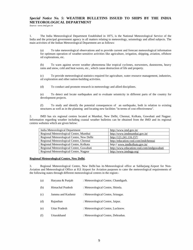
Special Notice No. 5: WEATHER BULLETINS ISSUED TO SHIPS BY THE INDIA METEOROLOGICAL DEPARTMENT Source: www.imd.gov.in
1. The India Meteorological Department Established in 1875, is the National Meteorological Service of the India and the principal government agency in all matters relating to meteorology, seismology and allied subjects. The main activities of the Indian Meteorological Department are as follows:
(a) To take meteorological observations and to provide current and forecast meteorological information for optimum operation of weather-sensitive activities like agriculture, irrigation, shipping, aviation, offshore oil explorations, etc.
(b) To warn against severe weather phenomena like tropical cyclones, norwesters, duststorms, heavy rains and snow, cold and heat waves, etc., which cause destruction of life and property.
(c) To provide meteorological statistics required for agriculture, water resource management, industries, oil exploration and other nation-building activities.
(d) To conduct and promote research in meteorology and allied disciplines.
(e) To detect and locate earthquakes and to evaluate seismicity in different parts of the country for development projects.
(f) To study and identify the potential consequences of an earthquake, both in relation to existing structures as well as in the planning and locating new facilities "in terms of cost effectiveness".
2. IMD has six regional centres located at Mumbai, New Delhi, Chennai, Kolkata, Guwahati and Nagpur. Information regarding weather including coastal weather bulletins can be obtained from the IMD and its regional centres websites which are given below:
India Meteorological Department http://www.imd.gov.in/ Regional Meteorological Centre, Mumbai http://www.imdmumbai.gov.in/ Regional Meteorological Centre, New Delhi http://121.241.116.157/ Regional Meteorological Centre, Chennai http://education.vsnl.com/imdchennai Regional Meteorological Centre, Kolkata http:// www.imdkolkata.gov.in/ Regional Meteorological Centre, Guwahati http://www.education.vsnl.com/imdguwahati Regional Meteorological Centre, Nagpur http://www.imdngp.org/
Regional Meteorological Centre, New Delhi.
3. Regional Meteorological Centre, New Delhi has its Meteorological office at Safdarjung Airport for Non-Aviation and Meteorological Office at IGI Airport for Aviation purposes to cater the meteorological requirements of the following states through different meteorological centres in the region:-
(a) Haryana & Punjab : Meteorological Centre, Chandigarh.
(b) Himachal Pradesh : Meteorological Centre, Shimla.
(c) Jammu and Kashmir : Meteorological Centre, Srinagar.
(d) Rajasthan : Meteorological Centre, Jaipur.
(e) Uttar Pradesh : Meteorological Centre, Lucknow.
(f) Uttarakhand : Meteorological Centre, Dehradun.
10
4. The activities of the centre are following:
(a) Aviation forecasting.
(b) Flood forecasting.
(c) Agromet Advisory.
(d) Rainfall monitoring on daily, weekly, monthly, seasonal and annual basis.
(e) Weather forecasting services to general public, Government agencies and other users for research and planning purposes.
(f) Implementation of District-wise Rainfall Monitoring Scheme (DRMS) of all states under the region and proving necessary inputs to user agencies.
(g) Earthquake Monitoring.
Regional Meteorological Centre, Chennai.
5. Regional Meteorological Centre at Chennai covers the states of Tamilnadu, Andhra Pradesh, Karnataka, Kerala and Union Territories of Pondicherry and Lakshadweep. The main activities of the centre are as follows:
(a) Under the technical and administrative control of the Regional Meteorological Centre, Chennai three Meteorological centres function at Hyderabad, Bangalore and Thiruvananthapuram to render meteorological services in their respective states.
(b) Area Cyclone warning centre at RMC Chennai supervises and coordinates the non-aviation forecasting work at Meteorological centres.
(c) Cyclone warning services are rendered through Area Cyclone Warning Centre, Chennai and Cyclone Warning Centre, Visakhapatnam.
(d) Meteorological Office at Chennai Airport (Minambakkam) controls and coordinates the aviation weather forecasting activities of the region.
(e) Cyclone Detection Radars located at Chennai, Machilipatnam, Visakhapatnam, Karaikal and Kochi track Tropical Cyclones over the Bay of Bengal and the Arabian Sea with their S-band 10 cm radars. The S-Band Radar at Chennai, Machilipatnam and Visakhapatnam have been replaced with Doppler Weather Radar and one indigenous Doppler Weather Radar has been installed at SHAR centre Sriharikota (Andhra Pradesh).
(f) High Resolution Picture Transmission (HRPT) direct readout ground station was established at RMC Chennai during June 1995. This received AVHRR(Advanced Very High Resolution Radiometer) satellite imageries and TOVS(TIROS Operational Vertical Sounder) data from polar orbiting satellite. As it went out of service, another receiving station has been established in 2010 to receive the METOP(Polar Orbiting Meteorological Satellites) and NOAA(National Oceanic and Atmospheric Administration) satellite data products.
(g) RMC Chennai also houses the Cyclone Warning Dissemination System (CWDS) unit from where the cyclone warning bulletins are disseminated to remote centres in coastal districts.
(h) Conventional Seismological Observatories are functioning at Thiruvananthapuram, Visakhapatnam, Vijayawada, Minicoy and Salem under this RMC. Seismological observatories under Global Seismological Network (GSN) were established at Chennai, Thiruvananthapuram and Visakhapatnam during 1997. An observatory under World Wide Standardised Seismological Network (WWSSN) is functioning at Kodaikanal. A broad Band System is functioning at Mangalore.
(j) Meteorological observations collected over a number of years form the basis of Climatology. Climatological data have wide applications and are utilized for planning large-scale national development

11
projects. Climatological sections at Regional Meteorological Centre and other meteorological centres in the region organise the scrutiny and archival of meteorological data and use them for answering various weather related enquiries.
(k) Accuracy of meteorological observations is ensured by periodical inspections of observatories by the inspectorate section at Regional Meteorological Centre and other Meteorological Centres. Calibrations of all instruments at observatories are checked at least once in two years.
(l) The state governments, Railways and other organisations, maintain more than 2000 rainguage stations. Periodical inspections of these raingauge stations are arranged through hydrology sections at RMC Chennai and other MCs.
(m) A training unit to cater the Basic Meteorological Training course was started at RMC Chennai during 1984. More than 1000 trainees in about 50 batches of four months duration each have already been trained so far.
(n) Agromet Advisory Units have started functioning at RMC Chennai and other MCs from 1978. These units are regularly issuing Agromet Advisory Bulletins twice a week for the benefit of the farming community in their respective states.
(p) RMC Chennai maintains 121 surface observatories (53 departmental and 68 part-time), 13 pilot balloon observatories, 10 Radiosonde/Rawin stations and 1 radiosonde station.
(q) Port Meteorological offices at Chennai, Kochi and Visakhapatnam maintains liaison with masters of ships and shipping companies and other marine interests.
6. E-mail addresses of various offices of RMC, Chennai are as follows:
Regional Meteorological Centre, Chennai http://education.vsnl.com/imdchennai [email protected] [email protected]
Area Cyclone Warning Centre, RMC Chennai [email protected] [email protected]
Meteorological Centre, Hyderabad [email protected] Meteorological Centre, Thiruvananthapuram [email protected] Meteorological Centre, Bangalore [email protected]
Cyclone Warning Centre, Vishakhapatnam [email protected] [email protected]
Regional Meteorological Centre, Mumbai. 7. The Regional Meteorological Center, Mumbai provides weather related services to the states of Maharashtra, Goa and Gujarat excluding Vidarbha region of Maharashtra State. The centre is also responsible for the monitoring of tropical cyclone formation in Arabian Sea and cyclone warning work. Cyclone warning work is carried out by Area Cyclone Warning Centre Mumbai and Cyclone Warning Centre Ahmedabad. The centre promulgates marine coastal weather bulletin pertaining to Maharashtra, Goa, Gujarat coasts and Arabian Sea. The activities of the centre are as follows: (a) Cyclone Warning Services for Maharashtra, Goa, Gujarat states and Arabian Sea. (b) Services to Aviation. (c) Services for Shipping and Fisheries, and Ports. (d) Inland Warning Services to District revenue, Irrigation and Railway. (e) Services to Public by issue of weather bulletins and warnings. (f) Services to Agriculture and Farmers. (g) Hydro meteorological and Flood Forecasting Services.

12
(h) Supply of Meteorological data members of public, Government Agencies and Industries for research and planning.
(j) Establish Meteorological observatories. (k) Analyse and interpret meteorological observations and issue forecasts. (l) Scrutinise and process observational data for climatological archives.
Regional Meteorological Centre, Kolkata 8. The center promulgates weather bulletin pertaining to West Bengal, Sikkim, Orissa, Bihar, Jharkhand, Tripura and the Andaman and Nicobar Islands. 9. For the benefit of the ships sailing on high seas and for coastal and fishing craft, weather bulletins are issued four times daily by the Area Cyclone Warning Centres at Mumbai, Kolkata and Chennai and the Cyclone Warning Centres at Ahmedabad, Bhubaneshwar and Vishakhapatnam. When there is a depression or cyclonic storm over the Bay of Bengal or Arabian Sea, the bulletins are issued more often during the course of the day and special warnings are issued for fishermen advising them not to venture out into the sea. The bulletins are broadcast through AIR. Fishermen’s associations also play an active role in disseminating fishermen’s warnings.
10. System of Port Warning Signals has been established at all major Indian ports, which are hoisted to warn the ships about impending danger from approaching storms. Full details of the bulletin and their broadcasts are available in that department's publication “Weather Service to Shipping, Fishing Vessels and Marine Interests, Third Edition 1998". A summary of these services is given in this Notice.
Coverage 11. The sea areas and coastal strips, defined as the strip of sea up to 75 Km from the coastline, covered by the weather bulletins, are given in the accompanying diagram which also indicates the nomenclatures of sub-areas of the Arabian Sea (Sea Area I) and the Bay of Bengal (Sea Area II) used in the bulletins. Categories 12. Weather Bulletins for Merchant Shipping are of the following categories:-
(a) Merchant Shipping Bulletins. These are for Sea Area I, broadcasted by the NAVTEX stations. Types and contents of these bulletins are described in paras 10-13. A detail of Merchant Shipping Bulletins is given in Appendix A. (b) Coastal Weather Bulletins. These are intended to give detailed information on those elements of weather in which coastal ships are most interested. Types and contents of these bulletins are described in paras 10, 14 and 15. (c) GMDSS –Full GMDSS service for weather forecast commenced w.e.f 01 Oct 98 through INMARSAT. Two bulletins at 0900 UTC and 1800 UTC are broadcasted daily.
Types of Weather Bulletins 13. Weather Bulletins issued by NAVTEX Stations are of the following types:-
(a) "Daily" bulletins are routine bulletins issued twice a day during normal weather. (b) "Extra” bulletin is issued, if considered necessary, when the weather is disturbed. However, an “Extra" bulletin is invariably issued when a depression is formed. (c) "Storm” bulletins - if a cyclonic Storm has just developed, followed by three additional "Storm” bulletins, one “extra" and two "daily" bulletins make a total of six bulletins a day Storm three i.e., GASBAG bulletin (1500 UTC) should be issued on routine basis during cyclone situation. Normally two bulletins are issued (AURORA and BALLOON) daily. In case a cyclonic storm has formed, HEXAGON a

13
special bulletin is issued additionally. Four more storm bulletins are issued (ELECTRON, FORMULA, GASBAG and DEWDROP), thus comprising six storm bulletins per day.
Code word for sea area bulletin
Code word for coastal bulletin
Chart on which based (UTC)
ELECTRON STORM ONE 0000 AURORA DAILY ONE 0300
FORMULA STORM TWO 0900 BALOON DAILY TWO 1200 GASBAG STORM THREE 1500
DEWDROP EXTRA 1800 HEXAGON SPECIAL -
(d) "Special" bulletin - if observations received, indicate unexpected development of weather, a “Special" bulletin is issued at any hour. Note: - In case of Coastal Weather Bulletin, the "Extra", "Storm" and "Special" bulletins for any given strip of coast are issued, if the disturbed weather/cyclonic Storm is likely to have a significant influence on the weather of that particular coastal strip. Such bulletins are prefixed by the International Safety Signal TTT.
Contents of Weather Bulletins 14. Merchant Shipping Bulletins. "Daily" bulletins issued for Sea Area I consist of the following parts:-
Part I. Storm warning in plain language prefixed by the International Safety Signal (TTT) as per details in Appendix B. This part is omitted during normal or seasonal weather.
Part II. Synopsis of weather conditions in the forecast in plain language Part III. Forecast in plain language. Part IV. Surface analysis in IAC (FLEET) Code. Part V. Surface reports from ships. Part VI. (i) Surface reports from selected Land Stations - in Code. (ii) Upper wind reports - in Code. 15. "Daily” bulletins issued consist of parts, I, II and III only. 16. The additional bulletins, viz, "Extra", "Storm" and "Special" issued consist of Part-I only and are prefixed by the International Safety signal (TTT). 17. Coastal Weather Bulletins consist of the following:- (a) Name of the coastal strip for which bulletin is issued. (b) Important Weather System, if any, affecting the weather over the coastal strip and its
movement in cases of Extra/Storm Bulletins. (c) Period of validity of forecast. (d) Forecast of Wind, Weather, Visibility and State of Sea for the Coastal strip. (e) Information about storm warning signals, if any, hoisted at ports on the coastal strip concerned. (f) Information on Storm Surges/Tidal waves is given whenever necessary. 18. The bulletin for coastal strip significantly affected by Gale winds cyclonic storms / severe cyclonic storms etc will be preceded by the international safety signal (TTT).

14
Descriptive Terminology for Monsoons 19. In the weather forecast and meteorological bulletins for sea areas and coastal bulletins issued by the Forecasting Officers of the India Meteorological Department during the South-West and North-East Monsoon periods, the intensity of the monsoon is classified as weak, moderate, etc., in terms of the wind speed over the sea area. The following specifications apply to the description of the intensity of monsoon over sea. Classification of Monsoon Corresponding wind speed Weak Up to 12 kn Moderate 13 to 22 kn Strong 23 to 32 kn Vigorous 33 kn and above. Port Meteorological Offices 20. Port Meteorological Offices (six in numbers) function at a number of Indian Ports to render assistance and advice to merchant ships on all meteorological matters. Address and telephone numbers of these offices are given in Appendix B. The important functions of the Port Meteorological Offices are: -
(a) To instruct and maintain liaison with the Meteorological offices and Captains and officers on board ships of the Indian Voluntary Observing Fleet, shipping companies and other marine interests, maintain and inspect and replace (whenever necessary) the meteorological instruments installed on board these ships. (b) On request from the master of any ship (irrespective of whether it is Indian or foreign ship) to check the meteorological instruments and to advise or assist in meteorological matters. (c) To instruct on matters pertaining to observations, keeping of meteorological log, forms/books and prompt transmission of weather reports. (d) To supply necessary forms, etc. (e) To supply weather information and (f) To promote and maintain co-operation with harbour authorities, shipping companies etc.

15
Appendix 'A' (Refers to para 12)
Details of Merchant Shipping Bulletins
1. When a tropical cyclone has formed or when gales, depressions, cyclonic storms etc; are expected; Part I (Storm Warning in plain language)of Merchant Shipping Bulletins contains the following items in the order given below:-
(a) International Safety Signals (TTT). (b) Statement of type of warning (Warning, Gale-Warning, Cyclone-Warning etc.) (c) Date and Time of disturbance in UTC, in the International six figure date time group. (d) Type of disturbance (Low, when it is expected to intensify into a Depression before broadcast of the next bulletin, Depression, monsoon-gale, cyclonic storm etc.) with a statement of central Pressure in hPa in the case of cyclonic storm intensity and above. (e) Location of disturbance in degree and tenths, where possible, of latitude and longitude. (Information given, as far as possible, according to the degree of certainty with which the center is located). (f) Forecast Direction and Speed of movement of disturbance (speed of storm center is given in knots; direction may be given to nearest of 16 points of compass or in degrees to nearest ten). (g) Extent of affected areas. (h) Speed and Direction of wind in various sections of the affected area.(Wind speeds are given, if possible for different distances from the center in the various sectors of the storm area. Wind speeds are given in knots; distance in nautical miles). (i) Further indications (if any).
2. Item (b) of the Storm Warning message, viz., the statement of the type of warning may be anyone of the following; the specification for each is as given in the table:- ----------------------------------------------------------------------------------------------------------------------------------------------- Type of Warning and disturbance Corresponding wind speed Beaufort Scale In knots ----------------------------------------------------------------------------------------------------------------------------------------------- (1) Warning: (i) Depression 17 – 27 5 - 6 *(ii) Deep Depression 28 - 33 7 ----------------------------------------------------------------------------------------------------------------------------------------------- (2) **Gale Warning (strong wind under steep pressure gradient, etc.) 34 - 47 8 – 9 ----------------------------------------------------------------------------------------------------------------------------------------------- (3) Cyclone Warning (cyclonic storm) 34 - 47 8 – 9 ----------------------------------------------------------------------------------------------------------------------------------------------- (4) Severe cyclone warning (i) Severe cyclonic storm 48 - 63 10 - 11 (ii) Very Severe Cyclonic Storm 64 – 119 12
(iii) Super Cyclonic Storm 120 and above ----------------------------------------------------------------------------------------------------------------------------------------------- * The term Deep Depression is not to be used in International Bulletins. ** Gale warning conditions (wind speed 34 kn. and above) occur in Indian sea areas usually in association with vigorous during south west monsoon season.

16
Appendix 'B' (Refers to para 14 and 20 )
Indian - Port Meteorological Offices Meteorological facilities are provided by the following Port Meteorological Offices (PMOs):-
Address Name of PMOs Contact Working Hours
Director Port Meteorological Office Regional Meteorological Centre Near RC Church Colaba Mumbai - 400005
Shri G Muralidharan AM II
Tel: 022 22174720 022 22151654 09833305617 (Shri G Muralidharan) Fax: 022 22154098 Email: [email protected]
0930-1800 5 days week
Director Port Meteorological Liaison Office Goa Observatory Alkimoh Panjim Goa - 403001
Shri ADJ D'souza AM II
Tel: 0832 2425547 09860998535 (Shri ADJ D'souza) Fax: 0832 2420161 Email: [email protected]
0930-1800
Director in-charge Port Meteorological Office Regional Meteorological Centre Inspectorate Section/PMO Unit New No.6, College Road Chennai - 600006
Shri E Kulandaivelu Director
Tel: 044 28230091 044 28230092 044 28230094
Ext. No. Inspectorate Section-234, 236, 230
Fax: 044 28271581 (ACWC Chennai) Email: [email protected] [email protected]
0915-1745
Director I/C Port Meteorological Office Cyclone Warning Center Kirlumpudi Opposite Andhra University out gate Vishakhapatnam - 530017
Shri GV Rama Krishna Rao AM I
Tel: 0891 2543031 0891 2543032 0891 2543034 0891 2543035 0891 2543036 09701499063 (Shri GV Rama Krishna Rao) 09441108415 (Shri J Malleswar) Fax: 0891 2543033 0891 2543036 Email: [email protected] [email protected]
0100-1700
Director I/C Regional Meteorological Centre 4 Duel Avenue Alipore Kolkata - 700027
Shri Ganesh Kumar Das Met Gr.I
Tel: 033 24793167 09836213781 (Shri GK Das) Fax: 033 24793167 Email: [email protected]
1000-1700
Director in charge Port Meteorological Office Cochin Port Trust Ex-Mahavir Plantahtion Building Opp. ICC Ltd., Indira Gandhi Road Willingdon Island, (South) Kochi - 682003
Shri M Sethumadhavan AM (II) At CDR Kochi
Tel: 0484 2667042 09446478262 (Shri GK Das) 09495779897 (Shri VL Rajendran SA) Email: [email protected]
0900-1730

17
16
18
Special Notice No. 6: WARNING TO PORTS AND STORM SIGNAL STATIONS Source: www.imd.gov.in 1. Storm warning Signals are part of Cyclone warning service of India Meteorological Department. The cyclone warning is one of the most important functions of the India Meteorological Department. It was the first service undertaken by the Department as early as in 1865. 2. The India Meteorological Department maintains a port warning service by which the port offices are warned by high priority telegrams and such other fast communication channels, about disturbed weather likely to affect their ports. On receipt of the warning telegrams from the ACWC/CWC, the port offices hoist appropriate visual signals prominently on signal masts so that they are clearly visible from a distance. 3. The storm warning signals are displayed prominently on masts in ports, are in the form of cones and cylinders for day-signals. During night red and white lamps are displayed in lighthouses for night- signals. In addition to hoisting signals, Port Officers have, in most cases, local arrangements for disseminating the information and warnings received by them, to country crafts and sailing vessels in the harbour. Mariners and other sea-faring people, including fishermen who may not be literate, are generally aware of the meaning of these signals. 4. At some ports, the meanings of the signals are displayed in English as well as in the local languages prominently on a notice board. While the India Meteorological Department is responsible for issuing the warnings, the port authorities arrange the display of signals. In addition to hoisting the signals, the port officers, in most cases, make arrangements for disseminating the warnings received by them, to country craft and sailing vessels in the harbour. 5. Ports in the maritime States are warned 5 to 6 times a day during periods of cyclonic storm by landline/ telegrams. The warnings contain information about the following:
(a) Location, intensity and expected direction of movement of the storm or depression,
(b) Part of the coast where it is expected to strike
(c) Type of signal, which the port should hoist.
Systems of Storm Warning Signals
6. A uniform system of storm warning signals was introduced at all the ports in India from 1st April 1898 and it is still popular with very little change. The system consists of:
(a) General System. This System has eleven signals. The ports where this system of signals are in use are called General ports. (b) Extended System. An Extended System, in addition to the eleven signals of the General System, has six Section signals to indicate the location of the disturbance. These additional signals are hoisted along with Distant Signals. This system is a special case of the General System and is in use only at a few ports on the East coast of India (Bay of Bengal). These ports are called as extended ports. There is no port under the Extended System in West coast of India. (c) Brief System. A Brief System consists of only five of the signals of the General Systems (viz. Signal Nos. III, IV, VII, X and XI). These are hoisted in association with prediction of bad weather at the port itself caused by disturbances out at sea. This system of signals is in use in ports used mainly by smaller vessels engaged in local traffic. These ports are called 'Brief ports'.

19
Pictorial Form of Visual Storm Warning Signals in Use
Signal Number
Description Day Signal
Night Signal
I DISTANT CAUTIONARY. There is a region of squally weather in which a storm may be forming.
II DISTANT WARNING. A storm has formed.
III LOCAL CAUTIONARY. The port is threatened by squally weather.
IV LOCAL WARNING. The port is threatened by a storm but it doesn't appear that the danger is as yet sufficiently great to justify extreme measures of precaution.
V DANGER. Port will experience severe weather from a cyclone expected to move keeping the port to the left of its track.
VI DANGER. Port will experience severe weather from a cyclone expected to move keeping the port to the right of its track.
VII DANGER. Port will experience severe weather from a cyclone expected to move over or close the port. Note: This signal is also hoisted when a storm is expected to skirt the coast without (actually) crossing it.
VIII GREAT DANGER. Port will experience severe weather from a severe cyclone expected to move keeping the port to the left of its track.
IX GREAT DANGER. Port will experience severe weather from a severe cyclone expected to move keeping the port to the right of its track.
X GREAT DANGER. Port will experience severe weather from a severe cyclone expected to move over or close the port. Note: This signal is also hoisted when a storm is expected to skirt the coast without (actually) crossing it.
XI FAILURE OF COMMUNICATION. Communications with the meteorological warnings centres has broken down and the local officer considered that there is a danger of bad weather.
7. Details of storm warning signals are given in the publication "Code of Storm Warning Signals" issued by the Indian Meteorological Department. 8. List of Storm Signal Stations on the Indian Coast is given below.

20
INDIA - WEST COAST
General System Alapuzha, Kochi (Cochin), Beypore, Kozhikode, Mangalore, Panambur, Karwar, Mumbai, Mormugao, J.N.P.T.(Raigad), Mandvi (Kachchh), Navlakhi, Bedi, Rozi, Okha, Porbander, Veraval, Bhavnagar, Magdalla, Alang, Jaffarabad, Mangrol, Sikka, Salaya, Dahej, Mundra, Pipavav, Dwaraka, Arnala, Rajapur Bay
Brief System Diu, Daman, Dahanu, Tarapur, Nawapur (Boisar), Satpati, Kalve Mahim, Dantiware
(Palghar), Bassein (Vasai), Uttan (Bhayandar), Kalyan, Thane, Manori (Malad), Versova (Andheri), Bandra, Trombay, Mora (Uran), Karanja, Mandwa, Thal, Revas, Alibag, Revdanda, Murud (Janjira), Rajapuri, Shrivardhan, Bankot, Harnai, Dabhol, Jaigad, Varoda (Malgund), Ratnagiri (Bhagawati Bunder), Purnagad, Jaitapur, Devgad, Achara, Malvan, Nivti (pat), Vengurla, Redi, Kiranpani, Panaji, Honavar, Kasaragod, Bhatkal, Gangoli (Coondapoor), Malpe, Azhikal (Beliapattanam), Kannur, Thalasserry, Ponnani, Thiruvananthapuram and Minicoy.
Ports which receive information
but hoist no signal at present :Rupen, Bharuch, Jakhau, Victor, Mul Dwarka, Ulwa, Belekeri (Avarsa), Tadri (Gokram), Kumta, Murdeshwar Note: - On receipt of warnings, the Port Officer at Gangoli (Coondapoor) transmits suitable warnings to
smaller ports of Hangarkotta and Bainduru which fall within his jurisdiction.
INDIA - EAST COAST
General System Tuticorin, Pamban, Puducherry, Nizamapatnam, Machilipatnam, Vishakhapatnam, Chatrapur, Krishnapatnam, Paradip, Diamond Harbour, Budge Budge, Ennore, Kolkata and Port Blair.
Brief System Kolachal, Rameswaram, Vadarevu, Bhimunipatnam, Kalingapatnam, Puri and Chandbali.
Extended System Nagapattinam, Cuddalore, Chennai, Kakinada and Sagar Island.
Port which receives information but hoists .... .... .... ... NIL no signals at present
21
Special Notice No. 7: DISTRESS AND RESCUE AT SEA - SHIPS AND AIRCRAFT Source: Indian List of Radio Signals Vol 5
GMDSS
1. The concept of a Global Maritime Distress Safety System (GMDSS) began as an idea at the International Maritime Organization (IMO) in 1973 and it entered into force in Feb 1999, after a 7-year introductory period. The requirement for ships to comply with the GMDSS is prescribed by SOLAS Chapter IV. This applies to all passenger vessels and all cargo vessels over 300 GT, if they are on international voyages. 2. The GMDSS has been designed according to the Master Plan published in the IMO GMDSS Handbook, a large volume which describes the entire system and its relevant equipment standards. The Master Plan shows the details behind the world network of Rescue Co-ordination centres (RCCs), each responsible for a given Search and Rescue (SRR) (see ILRS Vol 5 2011 Chapter 10). Each RCC is able to initiate Maritime Safety Information (MSI), which is broadcast in telex format via satellite and/or terrestrial radio. 3. GMDSS communication between ships and the RCCs is carried out using satellite and/or terrestrial radio sub-system. The satellite sub-systems provide communications between ships and shore, and the terrestrial sub-systems provide for both ship-shore and ship-ship communications. 4. The satellite sub-systems include earth stations for INMARSAT and Cospas-Sarsat service-the former provides both GMDSS and commercial services, the latter provides a distress alerting system which responds to signals form portable transmitter known as an EPIRB. 5. Terrestrial radio uses an automatic calling device to make initial contact, after which communications are carried out by voice or telex according to normal radio procedures. The automatic calling system is known as Digital Selective Calling. 6. Many types of vessels, regardless of size, are not required to comply with GMDSS. This group includes fishing vessels, warships; pleasure yachts not engaged in trade, wooden ships of primitive build, ships not propelled by mechanical means (e.g. sailing vessels) and ships in the Great Lakes. There is no internationally agreed standard of service for these vessels, although some states encourage their non-GMDSS vessels to participate in the GMDSS on voluntary basis. Provision of Distress and Safety services of non-GMDSS vessels is determined by individual flag states, and many countries continue to provide Maritime Safety Services of a non–GMDSS nature. The GMDSS is, in effect, interleaved with pre-existing systems, which have not been prohibited in any way, but merely made optional. Non-GMDSS distress and safety procedures are carried out in the same way as they were before the introduction of the GMDSS, i. e. according the ITU Radio Regulations Appendix 13. 7 The communication procedures for both GMDSS and non-GMDSS vessels are contained in the ITU Radio Regulations. The procedures for initiating and responding to DSC calls are also described in ITU Recommendation M.493-11 8. GMDSS watchkeeping at sea must be maintained in accordance with SOLAS Regs 12 and 16. The latter requires that a primary GMDSS operator shall be nominated to carry primary responsibility for communications during distress incidents. The provisions of STCW 95 must also be observed.

22
Overview of GMDSS operations
9. This is achieved by carrying out regular statutory tests. STCW 95 also requires that the primary GMDSS operator must be nominated on the ship's emergency muster list and adds further duties such as ensuring that GMDSS communications are conducted according to IMO and ITU procedures and that any necessary instructions is given to other operators. 10. The GMDSS like all communications systems continues to evolve with advancing technology. For example the identifying number of ITU Recommendation M.493-11 indicates the eleventh version of that particular Recommendation. Additionally, the following three IMO Committees publish circulars from time to time, to modify procedures and technical standards. (a) The Safety of Navigation (NAV) Sub-Committee, e.g. SN/Circ 197 (see ILRS Vol 5 2011 Appendix 4)
(b) The Radiocommunication and SAR (COMSAR) Sub Committee e.g. COMSAR/Circ. 17 (see ILRS Vol 5 2011 Chapter 3)
(c) The Maritime Safety Committee (MSC) 11. Several circulars have been published with the intention of reducing the number of accidental distress alerts The ITU Manual (Resolution 349) also contains procedures for canceling accidentals distress alerts. Normally, no action will be taken against a ship for transmitting a false alert, provided that it is duly cancelled. 12. It can be seen from the above that the GMDSS facilities, regulations and procedures are contained in several publications, e.g. IMO SOLAS Chapter IV; IMO GMDSS Handbook; IAMSAR Manual; STCW 95 Guidance on Radio Watchkeeping; ITU Radio Regulations and other ITU publications.

23
13. Operational Details. The type of equipment to be carried by each vessel, together with its maintenance arrangements and operating personnel is determined by a vessel's area of operation. Four Sea Areas have been defined according to the coverage of VHF, MF, HF Coast Radio Services and INMARSAT Services as follows.
DESCRIPTION OF GMDSS SEA AREAS
Area Description Distance Radio Frequencies EPIRBs Survival Craft
A1 Within range of shore-based
VHF stations
Depends on antenna height
at shore –based VHF
station, about 20-50 nm
VHF 156.525 MHz (Ch 70) for DSC or 156.8
MHz (Ch 16) RT
406 MHz Cospas-Sarsat
or VHF EPIRB
9 GHz radar transponder
(SART); VHF portable radio (Ch 16 and on
other frequency)
A2 Within range of shore-based MF stations
about 50-250 nm
MF VHF
as above, plus, 2187.5 kHz DSC,
2182 kHz RT, 2174.5 kHz NBDP, 518 kHz NAVTEX
406 MHz Cospas-Sarsat
as above
A3 Within geo-stationary satellite
range(i.e. Inmarsat)
70°N-70°S HF or Satellite
MF VHF
as above, plus 1.5-1.6 GHz alerting or as A1and A2 plus all
HF frequencies
406 MHz Cospas-Sarsat
as above
A4 Other areas (i.e. beyond
Inmarsat range)
North of 70°N or South of
70°S
HF MF
VHF
406 MHz Cospas-Sarsat
as above
BASIC EQUIPMENT (MINIMUM REQUIREMENTS INCLUDING DUPLICATION OF EQUIPMENT)
FOR SOLAS SHIPS
Equipment A1 A2 A3 Inmarsat Solution
A3 HF Solution
A4
VHF with DSC X X X X X DSC watch receiver channel 70 X X X X X MF telephony with MF DSC X X DSC watch receiver 2187.5 kHz X X Inmarsat ship earth station with EGC receiver X MF/HF telephony with DSC and telex X X DSC watch receiver MF/HF X X Duplicated VHF with DSC X X X Duplicated Inmarsat SES1 X Duplicated MF/HF telephony with DSC and telex1 X NAVTEX receiver 518 kHz X X X X X Float free satellite EPIRB X X X X X4
Radar transponder (SART) X2 X2 X2 X2 X2 Hand held GMDSS VHF transreceiver X3 X3 X3 X3 X3
For passenger ships the following has applied since 01.07.97 "Distress panel"(SOLAS Ch. IV/6.4 and 6.6) X X X X X Automatic updating of position to all relevant radiocommunication equipment (SOLAS Ch.IV/6.5)
X X X X X
Two-way-on-scene radiocommunication o 121.5 or 123.1 MHz from the navigating bridge (SOLAS Ch.IV/7.5)
X X X X X

24
COAST STATIONS IN INDIA 14. The Digital Selective Calling (DSC) Sub-System. DSC is a calling system that provides for distress, urgency and safety communications and also offers comprehensive facilities for routine communications, e.g. to initiate and to keep watch for automatic phone calls between ship and shore subscribers. The operator sets up calls using a DSC controller, and the controller is connected to a transreceiver. Sometimes both are contained in single unit. VHF DSC COAST STATIONS- INDIA STATION MMSI POSITION RANGE
( IN MILES) STATUS(ASSOCIATED RCCS)
Mumbai 004192203 18°55'N72°50'E 25 Operational (MRCC Mumbai) Chennai 004194401 13°06'N80°18'E 25 Operational (MRCC Chennai) Port Blair 004194409 11°41'N92°46'E 30 Operational (MRCC Port Blair) Porbandar 004192202 21°38'N69°37'E 25 Operational (MRCC Mumbai) New Mangalore 004192204 12°55'N74°48'E 25 Operational (MRCC Mumbai) Kochi 004192205 9°58'N76°16'E 20 Operational (MRCC Mumbai) Visakhapatnam 004194402 17°41'N83°17'E 20 Operational (MRCC Chennai) Paradip 004194403 20°16'N86°42'E 25 Operational (MRCC Chennai) Haldia 004194404 22°02'N88°06'E 25 Operational (MRCC Chennai) Diglipur 004194407 13°18'N93°04'E 25 Operational (MRCC Port Blair) Campbell Bay 004194408 7°00'N93°55'E 30 Operational (MRCC Port Blair) Goa 004192206 15°25'N73°48'E 25 Operational (MRCC Mumbai) Mandapam 004194406 9°17'N79°05'E 20 Operational (MRCC Chennai) Tuticorin 004194405 8°45'N78°12'E 20 Operational (MRCC Chennai) Okha 004192207 22°28'N69°05'E 20 Operational (MRCC Mumbai) Daman 004192201 20°25'N72°52'E 20 Operational (MRCC Mumbai) HF DSC COAST STATIONS-INDIA Station MMSI Operational
Frequency Bands Status (Associated RCCs)
Port Blair 004194409 4,6,8,12 & 16 MHz Operational (MRCC Port Blair) Porbandar 004192202 4,6,8,12 & 16 MHz Operational (MRCC Mumbai) Haldia 004194404 4,6,8,12 & 16 MHz Operational (MRCC Chennai) Mandapam 004194406 4,6,8,12 & 16 MHz Operational (MRCC Chennai) Daman 004192201 4,6,8,12 & 16 MHz Operational (MRCC Mumbai) INMARSAT STATION-INDIA Country Associated LES MRCC/Inmarsat Service Contact detail/Region Satellite India Pune MRCC Mumbai
Indian Coast Guard Region (West) Golfa Devi Temple Road Prabha Devi Post Mumbai – 400 025 India
Tel: +91 22 24316558/24388065 Fax: +91 22 24316558 E:mail : [email protected] [email protected] [email protected]
B C IOR

25
SATELLITE AIDED SEARCH AND RESCUE SYSTEM 15. Description. With the increase in commerce and trade, sea and air travel have increased manifold. Innovations in the designs of ships and aircraft have reduced accidents but have been little successful in totally eliminating them. The Cospas-Sarsat system provides distress alert and location information to Search And Rescue (SAR) authorities, anywhere in the world, from marine, air and land users in distress. The Cospas-Sarsat international satellite system for search and rescue consists of a constellation of satellites in polar and geostationary orbits and a network of ground stations.
COSPAS-SARSAT System Overview
16. Working of the System. The ship/aircraft carries an emergency transmitter, capable of being activated either manually or automatically in case of a disaster. The uplink units can be Emergency Locator Transmitters (ELTs), maritime Emergency Position Indicator Radio Beacons (EPIRBs) or Personal Locator Beacons (PLBs). The signals from these units are detected by Cospas-Sarsat orbiting satellites and relayed to a ground station termed as Local User Terminal (LUT), which processes the signals to determine the beacon location. Alerts are then relayed together with the location data, via a Mission Control Centre (MCC) to an appropriate RCC (Rescue Coordination Centre) or a SPOC (Search and Rescue Point of Contact). The location of beacons is determined by Doppler principle using the relative motion between the satellite and the beacon. With the precise measurement of Doppler and the knowledge of satellite orbit, position of distress signal can be estimated. The international distress frequencies used are 121.5 MHz, 243 MHz and 406 MHz. 17. The Cospas-Sarsat LEOSAR and GEOSAR System. The Cospas-Sarsat System includes two types of satellites:
(a) Satellites in low-altitude Earth orbit (LEO) which form the LEOSAR System (b) Satellites in geostationary Earth orbit (GEO) which form the GEOSAR System

26
18. The Inter Agency Steering Committee (IASC) consisting of representatives of Coast Guard, Directorate General of Shipping, Airport Authority of India, all three Defence services, Department of Telecommunication and Department of Electronics was set up in April 1986 with the Department of Space as the nodal agency. Two LUTs were set up, one at Bangalore (1989) and the other at Lucknow (1990). The Indian Mission Control Centre (INMCC), responsible for coordination with the rescue coordination centres, and other international MCCs is co-located with the Bangalore LUT. The system operations are fully automated. The INMCC is connected with the Rescue Coordination Centres of the Airports Authority of India and transmits distress alerts received from the areas covered under these RCCs. EMERGENCY POSITION INDICATION RADIO BEACONS(EPIRB)
19. Description. In the field of Search and Rescue (SAR), distress radio beacons, also collectively known as distress beacons, emergency beacons, or simply, beacons, are tracking transmitters which aid in the detection and location of boats, aircraft, and/or persons in distress. Marine distress beacons or emergency beacons are known as EPIRBs (Emergency Position Indicating Radio Beacons) which are a component of the Global Maritime Distress Safety System (GMDSS). Most commercial off-shore working vessels with passengers are required to carry a self-deploying EPIRB, while most in-shore and fresh-water craft are not. EPIRBs interface with Cospas-Sarsat, the international satellite system for Search and Rescue. When activated, such beacons send out a distress signal that, when detected by non-geostationary satellites, can be located by triangulation. In the case of 406 MHz beacons which transmit digital signals, the beacons can be uniquely identified almost instantly (via GEOSAR), and furthermore, a GPS position can be encoded into the signal which provides instantaneous identification of the registered user and its location.Often using the initial position provided via the satellite system, the distress signals from the beacons can be detected by SAR aircraft and ground search parties can home in on the distress signals from the beacons and come to the aid of the concerned boat, aircraft, or people Most EPIRBs are waterproof and fit in a cube about 30 cm on a side, and weigh 2 to 5 kg (4 to 11 lb). They can be purchased from marine suppliers. The units have a useful life of 10 years, operate across a range of conditions (−40°C/°F to +40°C/+104°F), and transmit for 24 to 48 hours.
20. Beacon Modes. The most important aspect of a beacon in classification is the mode of transmission. There are two valid transmission modes: digital and analog.
(a) Digital Mode - 406 MHz Beacons. 406 MHz beacons transmit bursts of digital distress information to orbiting satellites, and may also contain a small integrated analog (121.5 MHz) homing beacon. Advanced 406 MHz beacons are capable of transmitting a highly-accurate GPS location within their distress message; thus, the process of distress relief simply becomes "rescue" instead of "Search and Rescue." The distress message transmitted by a 406 beacon contains the information such as:
(i) Which country the beacon is from, (ii) A unique 15-digit hexadecimal beacon identification code (a "15-hex ID"),
(iii) The encoded identification of the vessel or aircraft in distress, either as an MMSI value, or as, in the case of an ELT, either the aircraft's registration or its ICAO 24-bit address (from its Mode-S transponder (iv) When equipped, a GPS position.
(v) Whether or not the beacon contains a 121.5 MHz "homer"
(vi) 406 beacons transmit for a quarter of a second immediately when turned on, and then transmit a digital burst once every 50 seconds thereafter. Both GEOSAR and LEOSAR satellites monitor these signals.
(vii) 406 beacons will be the only beacons compatible with the MEOSAR (DASS) system. (viii) 406 MHz beacons must be registered.

27
(b) Hex Codes. The digital distress message generated by the beacon varies according to the above factors and is encoded in 30 hexadecimal characters. The unique 15-character digital identity (the 15-hex ID) is hard-coded in the firmware of the beacon. SAR authorities refer to the distress messages and the identity transmitted by 406 beacons, variously, as "hex codes.". For example hex codes look like the following: 90127B92922BC022FF103504422535
(i) A bit telling whether the message is short (15 hex digits) or long (30 hex digits) format. (ii) A country code, which lets the worldwide COSPAS/SARSAT central authority identify the national authority responsible for the beacon. (iii) Embedded 15-Hex ID or 15-hex transmitted distress message, for example, 2024F72524FFBFF The hex ID is printed or stamped on the outside of the beacon and is hard-coded into its firmware. The 15-hex ID can only be reprogrammed by certified distress radio beacon technicians. The national authority uses this number to look up phone numbers and other contact information for the beacon. This is crucial to handle the large number of false alarms generated by beacons (iv) A location protocol number and type of location protocol: EPIRB or MMSI, as well as all the data fields of that location protocol. If the beacon is equipped with GPS or GLONASS, a rough (rounded) latitude and longitude giving the beacon's current position. In some aircraft beacons, this data is taken from the aircraft's navigation system. (v) When a beacon is sold to another country, the purchaser is responsible for having the beacon reprogrammed with a new country code and to register it with his/her nation's beacon registry, and the seller is responsible to de-register the deprecated beacon ID with his/her national beacon registry. (vi) One can use the beacon decoder web page] at Cospas-Sarsat to decrypt/extract the 15-hex ID from the 30-hex distress message
(c) Analog Mode - All Other Beacons
(i) A simple analogue siren tone is transmitted continuously until the battery dies.
(ii) In the case of 121.5 MHz beacons, the frequency is monitored by most commercial airliners
(iii) The Cospas-Sarsat system can only detect this type of beacon when a LEOSAR satellite is in view of both the beacon and a LEOLUT (satellite dish). Satellite detection of 121.5 MHz beacons ceased on 1 February 2009.
21. Frequencies. Distress beacons transmit distress signals on the following key frequencies; the frequency used distinguishes the capabilities of the beacon. A recognized beacon can operate on one of the three (currently) Cospas-Sarsat satellite-compatible frequencies. In the past, other frequencies were also used as a part of the search and rescue system.
(a) Cospas-Sarsat (satellite) Compatible Beacon Frequencies
(i) 406 MHz UHF- carrier wave at 406.025 MHz ± 0.005 MHz (ii) 121.5 MHz VHF ± 6 kHz (frequency band protected to ±50 kHz). (Satellite detection ceased on 1 February 2009, but this frequency is still used for short-range location during a search and rescue operation)
(b) Cospas-Sarsat Incompatible Beacon Frequencies
(i) Marine VHF radio channels 15/16 - these channels are used only on the obsolete Class C EPIRBs (ii) The obsolete Inmarsat-E beacons transmitted to Inmarsat satellites on 1646 MHz UHF.
28
22. EPIRB Sub-Classification. EPIRBS are sub-classified as follows:
(a) Recognized Categories:
(i) Category I - 406/121.5 MHz. Float-free, automatically activated EPIRB. Detectable by satellite anywhere in the world. Recognized by GMDSS.
(ii) Category II - 406/121.5 MHz. Similar to Category I, except is manually activated. Some models are also water activated.
(b) Unrecognized Classes:
(i) Class A - 121.5/243 MHz. Float-free, automatically-activating. These devices have been phased out by the FCC and are no longer recognized.
(ii) Class B - 121.5/243 MHz. Manually activated version of Class A. These devices have been phased out by the FCC and are no longer recognized.
(iii) Class S - 121.5/243 MHz. Similar to Class B, except it floats, or is an integral part of a survival craft (lifeboat). These devices have been phased out by the FCC and are no longer recognized.
(iv) Class C - Marine VHF ch15/16. Manually activated, these beacons operate on maritime channels only, and therefore are not detectable by satellite or normal aircraft. These devices have been phased out and are no longer recognized.
(v) Inmarsat-E - This service ended 1 December 2006; all former users have switched to Category I or II 406 MHz EPIRBS. These beacons were float-free, automatically activated EPIRBs operated on 1646 MHz. They were detectable by Inmarsat geostationary satellites, and were recognized by GMDSS.
23. Activation Methods. There are two ways to activate a beacon; manually and/or automatically. Automatic EPIRBs are water activated, while automatic ELTs are G-force (impact) activated. Some EPIRBs also deploy; this means that they physically depart from their mounting bracket on the exterior of the vessel (usually by going into the water.) For a marine EPIRB to begin transmitting a signal (or "activate") it first needs to come out of its bracket (or "deploy"). Deployment can happen either manually—where someone has to physically take it out of its bracket—or automatically—where water pressure will cause a hydrostatic release unit to release the EPIRB from its bracket. If it does not come out of the bracket it will not activate. There is a magnet in the bracket which operates a reed safety switch in the EPIRB. This is to prevent accidental activation when the unit gets wet from rain or shipped seas. Once deployed, EPIRBs can be activated, depending on the circumstances, either manually or automatically (as soon as water comes into contact with the unit's "sea-switch".) All modern EPIRBs provide both methods of activation and deployment.
24. Phase out of 121.5& 243 MHz beacons. Since 1 February 2009, only 406 MHz beacons are detected by the international Cospas-Sarsat SAR satellite system. This affects all maritime beacons (EPIRBs), all aviation beacons (ELTs) and all personal beacons (PLBs). In other words, Cospas-Sarsat has ceased satellite detection and processing of 121.5/243 MHz beacons. These older beacons are now only detectable by ground-based receivers and aircraft. Despite the switch to 406 MHz, pilots and ground stations are encouraged to continue to monitor for transmissions on the emergency frequencies, as many 406 beacons are also equipped with 121.5 "homers." Furthermore, the 121.5 MHz frequency continues to be used as a voice distress frequency (especially in aviation).
25. SAR Response to Various Beacons. Emergency beacons operating on 406 MHz transmit a unique 15, 22, or 30 character serial number called a Hex Code. When the beacon is purchased the Hex Code should be registered with the relevant national (or international) authority. Registration provides Search and Rescue agencies with crucial information such as:

29
(a) Phone numbers to call,
(b) Description of the vessel, aircraft, vehicle, or person (in the case of a PLB)
(c) Home port of a vessel or aircraft,
(d) Any additional information that may be useful to SAR agencies .
Registration information allows SAR agencies to start a rescue more quickly. For example, if a shipboard telephone number listed in the registration is unreachable, it could be assumed that a real distress event is occurring. Conversely, the information provides a quick and easy way for the SAR agencies to check and eliminate false alarms (potentially sparing the owner of the beacon thousands of dollars in negligent false alert fines.). An unregistered 406 beacon still carries some information, such as the manufacturer and serial number of the beacon. Despite the clear benefits of registration, an unregistered 406 beacon is very substantially better than a 121.5/243.0 beacon; this is because the Hex Code received from a 406 beacon confirms the authenticity of the signal as a real SAR alert. Beacons operating on 121.5 and/or 243.0 MHz simply transmit an anonymous siren tone, and thus carry no information to SAR agencies. Such beacons implicitly rely on the Doppler location detection system. SAR authorities have no way of knowing whether a 121.5/243.0 MHz signal is actually a SAR signal until they physically deploy to the location and home in on the source (and sound) of the transmission. Since SAR resources are scarce (and expensive), most countries do not deploy the most useful SAR homing assets (aircraft) until ambiguity has been resolved.
26. Working of EPIRBs. All the systems work something like this: A beacon is activated by a crash, a sinking, or manually by survivors. The beacon's transmission is picked up by one or more satellites. The satellite transmits the beacon's signal to its ground control station. The satellite's ground station processes the signals and forwards the data, including approximate location, to a national authority. The national authority forwards the data to a rescuing authority. The rescuing authority uses its own receiving equipment to locate the beacon and makes the rescue or recovery. Once the satellite data is in, it takes less than a minute to forward the data to any signatory nation. There are several systems in use, with beacons of varying expense, different types of satellites and varying performance. Note that even the oldest systems provide an immense improvement in safety, compared to not having a beacon.
(a) GPS-Based, Registered. The most modern 406 MHz beacons with GPS locate a beacon with a precision of 100 meters, anywhere in the world, and send a serial number so the government authority can look up phone numbers to notify next-of-kin in four minutes, with rescue commencing shortly afterward. The GPS system permits stationary, wide-view geosynchronous communications satellites to enhance the doppler position received by low Earth orbit satellites. EPIRB beacons with built-in GPS are usually called GPIRBs, for GPS Position-Indicating Radio Beacon or Global Position-Indicating Radio Beacon.
(b) High-Precision Registered. An intermediate technology 406 MHz beacon has world-wide coverage, locates within 2 km (12.5 km² search area), notifies kin and rescuers in 2 hours maximum (46 min average), and has a serial number to look up phone numbers, etc. This can take up to two hours because it has to use moving weather satellites to locate the beacon. To help locate the beacon, the beacon's frequency is controlled to 2 parts per billion, and its power is a hefty five watts. Both of the above types of beacons usually include an auxiliary 25 milliwatt beacon at 121.5 MHz to guide rescue aircraft.
27. Location by Doppler (Without GPS). When the beacon has no GPS receiver, the system locates the beacon from its Doppler shift as received by the quickly-moving satellites. Using the same techniques as radar, basically, the frequency received varies depending on the speed of the beacon relative to the satellite. The amount of shift is proportional to the range and bearing to the satellite. The instant the beacon's Doppler shift changes from high to low indicate the time when the bearing from the beacon to the satellite's ground track is 90 degrees. The side of the satellite track is determined because the rate of change of the Doppler shift is faster when the Earth is turning towards the satellite track. One key to an effective Doppler position triangulation is excellent frequency stability. If the signal is not monotone (stable), then the results of the triangulation will vary. This is why 406 MHz beacons can be triangulated to within 5km and the b-side (unlikely mirror position) can be ruled out with 98.5% accuracy, whereas the old technology of analog beacons is only accurate to within a 20 km radius per mirror image, each of which is roughly

30
equally likely to be the correct position. In order to handle multiple simultaneous beacons, modern 406 MHz beacons transmit in bursts, and remain silent for a few seconds. This also conserves transmitter power. 28. Satellites Used. Receivers are auxiliary systems mounted on several types of satellites. This substantially reduces the program's cost. The weather satellites that carry the SARSAT receivers are in "ball of yarn" orbits, inclined at 99 degrees. The longest period that all satellites can be out of line-of-sight of a beacon is about two hours. The first satellite constellation was launched in the early 1970s by the Soviet Union, Canada, France and the USA. Some geosynchronous satellites have beacon receivers. Since end of 2003 there are four such geostationary satellites (GEOSAR) that cover more than 80% of the surface of the earth. As with all geosynchronous satellites, they are located above the equator. The GEOSAR satellites do not cover the polar caps. Since they see the Earth as a whole, they see the beacon immediately, but have no motion, and thus no doppler frequency shift to locate it. However, if the beacon transmits GPS data, the geosynchronous satellites give nearly instantaneous response. Cospas-Sarsat defines standards for beacons, auxiliary equipment to be mounted on conforming weather and communication satellites, ground stations, and communications methods. The satellites communicate the beacon data to their ground stations, which forward it to main control centers of each nation that can initiate a rescue effort. 29. Registration of EPIRBs. A website (http://inmcc.istrac.org ) has been created by Indian Mission Control Centre (INMCC), Bangalore which has commenced web based beacon registration w.e.f 15 Aug 2006. The registration of EPIRBs is compulsory as per national and international requirements (ICAO/ IMO/DG Shipping/DG Civil Aviation). It is free of charge and the help is extended with no loss of time in case of distress. Non-registration and inadvertent activation of beacons may be subjected to necessary disciplinary action. Beacon registration data includes primary and alternate emergency points of contact that SAR forces can call when a distress signal is received. Additional information is also included. For EPIRBs the vessel name, type, length, colour, capacity and homeport are listed as well as type of communication equipment and call sign. For ELTs, the aircraft number, make, model, colour, capacity and home airport/FBO are listed. Both registration forms also contain room for additional information that may help locate the vessel or aircraft sooner. The registration of beacon helps discriminate false alarms quickly saving SAR resources and efforts by the SAR forces. The registration information is stored securely at the INMCC and used only for search and rescue purposes. INMCC has standardised the EPIRBs registration format as per the international requirements, and made it available online for the users. On home page, you will find under login “New User”. Go to this and join as new user by providing all the required details. After you finish this, INMCC will receive your profile to authorise you as registered user, and will provide you username and password by email. After receiving the username/password, please change password of your choice using an option provided in the software after log-in. After registering with INMCC, you can register/deregister your beacon or update the existing information directly using on line Beacon Registration Facility. Most of the existing users and beacons have been registered and made available online. You may access the information and update the data as appropriate. Information contained in the beacon registration database is critical to search and rescue operations and to your personal safety. It is our responsibility to ensure the details are kept up to date as it will help make life-saving job a lot easier when you most need it. The contact details of INMCC are as follows:-
(a) Indian Mission Control Centre (INMCC) ISRO Telemetry Tracking and Command Network (ISTRAC) Indian Space Research Organization (ISRO) Govt. of India/Dept. of Space Plot no. 12, Peenya Industrial Estate Bangalore-560058
(b) For operations related matters:- Indian Mission Control Centre (INMCC), Bangalore
AFTN VOBG YCYS
Telephone + 91 80 2809 4546
TeleFax + 91 80 2837 1857
e-mail [email protected]
INMCC Website http://inmcc.istrac.org/
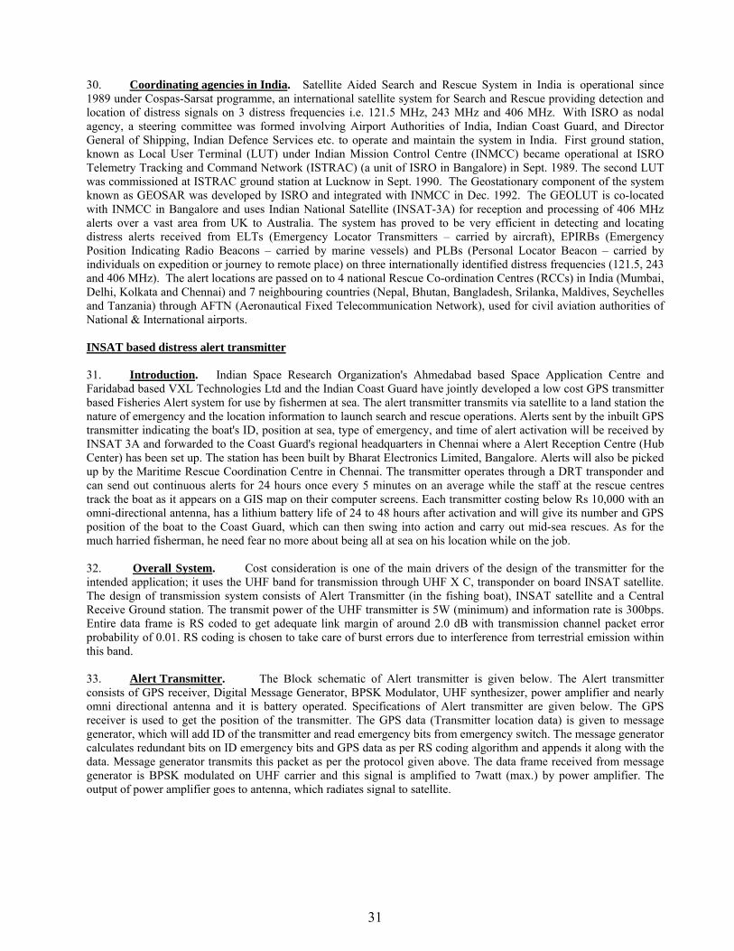
31
30. Coordinating agencies in India. Satellite Aided Search and Rescue System in India is operational since 1989 under Cospas-Sarsat programme, an international satellite system for Search and Rescue providing detection and location of distress signals on 3 distress frequencies i.e. 121.5 MHz, 243 MHz and 406 MHz. With ISRO as nodal agency, a steering committee was formed involving Airport Authorities of India, Indian Coast Guard, and Director General of Shipping, Indian Defence Services etc. to operate and maintain the system in India. First ground station, known as Local User Terminal (LUT) under Indian Mission Control Centre (INMCC) became operational at ISRO Telemetry Tracking and Command Network (ISTRAC) (a unit of ISRO in Bangalore) in Sept. 1989. The second LUT was commissioned at ISTRAC ground station at Lucknow in Sept. 1990. The Geostationary component of the system known as GEOSAR was developed by ISRO and integrated with INMCC in Dec. 1992. The GEOLUT is co-located with INMCC in Bangalore and uses Indian National Satellite (INSAT-3A) for reception and processing of 406 MHz alerts over a vast area from UK to Australia. The system has proved to be very efficient in detecting and locating distress alerts received from ELTs (Emergency Locator Transmitters – carried by aircraft), EPIRBs (Emergency Position Indicating Radio Beacons – carried by marine vessels) and PLBs (Personal Locator Beacon – carried by individuals on expedition or journey to remote place) on three internationally identified distress frequencies (121.5, 243 and 406 MHz). The alert locations are passed on to 4 national Rescue Co-ordination Centres (RCCs) in India (Mumbai, Delhi, Kolkata and Chennai) and 7 neighbouring countries (Nepal, Bhutan, Bangladesh, Srilanka, Maldives, Seychelles and Tanzania) through AFTN (Aeronautical Fixed Telecommunication Network), used for civil aviation authorities of National & International airports. INSAT based distress alert transmitter 31. Introduction. Indian Space Research Organization's Ahmedabad based Space Application Centre and Faridabad based VXL Technologies Ltd and the Indian Coast Guard have jointly developed a low cost GPS transmitter based Fisheries Alert system for use by fishermen at sea. The alert transmitter transmits via satellite to a land station the nature of emergency and the location information to launch search and rescue operations. Alerts sent by the inbuilt GPS transmitter indicating the boat's ID, position at sea, type of emergency, and time of alert activation will be received by INSAT 3A and forwarded to the Coast Guard's regional headquarters in Chennai where a Alert Reception Centre (Hub Center) has been set up. The station has been built by Bharat Electronics Limited, Bangalore. Alerts will also be picked up by the Maritime Rescue Coordination Centre in Chennai. The transmitter operates through a DRT transponder and can send out continuous alerts for 24 hours once every 5 minutes on an average while the staff at the rescue centres track the boat as it appears on a GIS map on their computer screens. Each transmitter costing below Rs 10,000 with an omni-directional antenna, has a lithium battery life of 24 to 48 hours after activation and will give its number and GPS position of the boat to the Coast Guard, which can then swing into action and carry out mid-sea rescues. As for the much harried fisherman, he need fear no more about being all at sea on his location while on the job. 32. Overall System. Cost consideration is one of the main drivers of the design of the transmitter for the intended application; it uses the UHF band for transmission through UHF X C, transponder on board INSAT satellite. The design of transmission system consists of Alert Transmitter (in the fishing boat), INSAT satellite and a Central Receive Ground station. The transmit power of the UHF transmitter is 5W (minimum) and information rate is 300bps. Entire data frame is RS coded to get adequate link margin of around 2.0 dB with transmission channel packet error probability of 0.01. RS coding is chosen to take care of burst errors due to interference from terrestrial emission within this band. 33. Alert Transmitter. The Block schematic of Alert transmitter is given below. The Alert transmitter consists of GPS receiver, Digital Message Generator, BPSK Modulator, UHF synthesizer, power amplifier and nearly omni directional antenna and it is battery operated. Specifications of Alert transmitter are given below. The GPS receiver is used to get the position of the transmitter. The GPS data (Transmitter location data) is given to message generator, which will add ID of the transmitter and read emergency bits from emergency switch. The message generator calculates redundant bits on ID emergency bits and GPS data as per RS coding algorithm and appends it along with the data. Message generator transmits this packet as per the protocol given above. The data frame received from message generator is BPSK modulated on UHF carrier and this signal is amplified to 7watt (max.) by power amplifier. The output of power amplifier goes to antenna, which radiates signal to satellite.
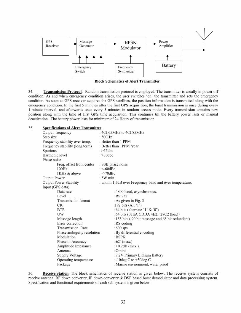
32
34. Transmission Protocol. Random transmission protocol is employed. The transmitter is usually in power off condition. As and when emergency condition arises, the user switches ‘on’ the transmitter and sets the emergency condition. As soon as GPS receiver acquires the GPS satellites, the position information is transmitted along with the emergency condition. In the first 5 minutes after the first GPS acquisition, the burst transmission is once during every 1-minute interval, and afterwards once every 5 minutes in random access mode. Every transmission contains new position along with the time of first GPS time acquisition. This continues till the battery power lasts or manual deactivation. The battery power lasts for minimum of 24 Hours of transmission. 35. Specifications of Alert Transmitter.
Output frequency : 402.65MHz to 402.85MHz Step size : 500Hz Frequency stability over temp. : Better than 1 PPM Frequency stability (long term) : Better than 1PPM /year Spurious : >55dbc Harmonic level : >30dbc Phase noise Freq. offset from center : SSB phase noise 100Hz : <-60dBc 1KHz & above : <-70dBc Output Power : 5W min Output Power Stability : within 1.5dB over Frequency band and over temperature. Input (GPS data)
Data rate : 4800 baud, asynchronous. Level : RS 232 Transmission format : As given in Fig. 3 CR :192 bits (All ‘1’) BTR : 64 bits (alternate ‘1’ & ‘0’) UW : 64 bits (07EA CDDA 4E2F 28C2 (hex)) Message length : 155 bits ( 90 bit message and 65 bit redundant) Error correction : RS coding Transmission Rate : 600 sps Phase ambiguity resolution : By differential encoding Modulation : BSPK Phase in Accuracy : ±2º (max.) Amplitude Imbalance : ±0.2dB (max.) Antenna : Omini Supply Voltage : 7.2V Primary Lithium Battery Operating temperature : -10deg.C to +50deg.C Package : Marine environment, water proof
36. Receive Station. The block schematics of receive station is given below. The receive system consists of receive antenna, RF down converter, IF down-converter & DSP based burst demodulator and data processing system. Specification and functional requirements of each sub-system is given below.
Message Generator
Frequency Synthesizer
Power Amplifier
BPSK Modulator
Block Schematics of Alert Transmitter
GPS Receiver
Emergency Switch
Battery
GPS Receiver

33
37. Specification of Receive Station. Antenna & RF System: Receive frequency (3.0m) : 4505MHz (nominal) G/T of Receive station : 19dB/K Output IF frequency band : 70MHz (nominal) Level : -40dBm (nominal) IF Down Converter and Burst Demodulator: Input frequency band : 70 MHz (nominal) Input level : -40dBm (nominal) Modulation : BPSK Burst format : as per Fig-3 Output Info. Rate : 600 sps 38. Description of Receive System. The satellite signal in Ext. C-band is received by ground terminal consisting of 3m antenna. The 3-meter antenna is a solid dish antenna with G/T of 19dB/K. The antenna can be moved over 90° elevations and 360° azimuths. RF system consists of Low Noise Amplifier (LNA), and RF Down converter. A Low Noise amplifier is fitted with feed system amplifies the low-level signal received by antenna. Output of LNA goes to RF down converter, which converts RF signal into IF signal (70�18MHz). The frequency of IF is settable. 70 MHz IF signal goes to IF down converter and DSP based burst demodulator. The IF down converter converts 70 MHz input signal to a fixed IF of 9.0 KHz. The 9 KHz signal goes to DSP based burst demodulator, developed at SAC. The 9 KHz signal may have frequency offset due to transmitter frequency offset as well as due to satellite frequency offset. The DSP based BPSK burst demodulator has capability to track 9 kHz�5 kHz signal. The 9 kHz BPSK modulated signal is given to the burst demodulator. In the burst demodulator the 9 kHz signal first given to an Analog to Digital converter followed by DSP (AD21062 Processor). The DSP first looks for carrier frequency estimation. The process of estimation is continues till it receives the signal. On detection of the carrier the DSP processor starts demodulation of the signal and differentially decoded synchronous data at 600 sps is obtained. An interface card converts the synchronous data to asynchronous data at 4800 baud, which goes to data processing system (PC). RS decoding is done in the PC with software developed at SAC. The data processing system consists of Pentium-IV PC platform that receives data on com. port and process the data and stores it. The PC displays the received data on-line and also acts as Web Portal for on-line accessing the position and emergency condition of the transmitter. The Web portal is developed at SAC. SEARCH AND RESCUE TRANSPONDERS 39. Description. Search And Rescue Transponders are electronic units which react to the emissions of X-band radars. Each time a SART detects a pulse from X-band radar it transmits a signal which is displayed on the screen of the radar which activated it. This can greatly help a would-be rescuer to locate a liferaft. They can be thought of as 'active' radar reflectors as they electronically enhance the echo received by radar. All compulsory GMDSS vessels up to 500 tons must carry at least one SART. Above 500 tons, they must carry two. Non-compulsory vessels are strongly advised to carry at least one to aid in any possible rescue.
LNA & D/C
BPSK Burst
DEMOD
70MHz IF 600sps
C-BAND
Data Processing
&Web portal
Internet
3m

34
40. Operation of SART and Test Procedures. A SART has a receiver which scans for UHF signals between 9.2 and 9.5 GHz - the frequencies on which X-band radar transmits its signal. As soon as the SART detects a signal it immediately transmits its own signal on the same frequency. This signal consists of a series of twelve pulses, and these are displayed on the screen of the radar as a series of twelve echoes with a gap of 0.6 miles between each of them. The first dot is at the position of the SART, with the remainder radiating in a straight line towards the edge of the screen. As the rescue vessel approaches the SART, the twelve dots each become short arcs. These arcs increase in size as the vessel gets closer, until the signal from the SART is permanently activated by the weakest side-lobes from the radar transmission. The signal from the SART becomes twelve concentric circles on the radar screen and this tells the would-be rescuers that they have more or less arrived. When a SART is switched on it will show a light to indicate that it is working. An approved SART should have sufficient power to operate in this stand-by mode for at least 96 hours. When it receives a signal from X-band radar, and transmits its own signal, it will either flash this indicating light or in some cases a second light or even a buzzer. This will serve to let the distressed persons know that approaching radar is activating the SART. If the survivors have handheld VHF with them then this would be a good time to use it to try calling the approaching ship. Since the radar UHF signals can only effectively travel in a straight line, the distance from which a SART can be activated by radar is dependent on its own height and the height of the interrogating radar scanner. Most SARTs have an extendible handle to help in positioning it as high as possible in the liferaft or lifeboat. The SART must be secured outside the canopy of the liferaft. Operating it from inside the liferaft will greatly reduce its effectiveness. The International Maritime Organisation stipulates that a SART mounted at a height of one metre must be detectable by a ship's radar with a scanner height of 15 metres at, distance of at least 5 miles. It has been found from tests that a ship's radar will usually detect a SART laying flat on the floor of a liferaft at around 1.8 miles. If the SART is upright on the floor the detection range increases to about 2.5 miles. It should be possible, under most conditions, to mount the SART at least two metres high. A normal detection range for a SART mounted two metres above sea level by an average ship's radar is about seven to ten miles. However, a search aircraft equipped with X-band radar should be able to detect it from at least 30 miles when flying at an altitude of around 3,000 feet. All SARTs should be checked on a weekly basis for any physical damage and for the expiration date of the battery. This is normally indicated on the manufacturer's plate affixed to the SART. It is permitted to check the operation of a SART by briefly turning it on and exposing it to the transmissions of the ship's radar. If this is done on board, then the radar screen will be flooded with the concentric circles, showing the proximity of the SART. Such tests should be conducted on a monthly basis and should be kept short so as not to shorten the life of the battery too much and to reduce the risk of other vessels seeing it, resulting in a false distress alert. Ideally, such tests should be conducted when there are no other vessels within radar range so as not to cause interference or false alarms. Vessels which are using their radar to look for a SART should use a range of 6 or 12 miles on the radar for optimum results. If a shorter range is selected, the narrower bandwidth used in the receiver will reduce the brightness of the dots making them harder to see. There is no point in using a longer range; since the maximum distance a SART will be detectable from another vessel is 7 to 10 miles. There are some SARTs which have a so-called anti-collision mode. When operated in this mode they transmit five pulses instead of the normal twelve. Such a unit may well help the radar operator on an approaching ship to see you, but there is a danger that it might be mistaken for the distress signal and the ship may possibly try to rescue you, even if you were not in distress. Such use of a SART is not encouraged. Under distress conditions though, there is no doubt that a SART is a valuable aid for any vessel to carry. It will greatly facilitate any search and rescue operation. 41. The nature of action taken by these authorities when a casualty happens or is imminent depends on whether a ship or an aircraft is involved, position of the casualty and in circumstances in which it occurs. It will be seen that the circumstances attending a casualty vary considerably and the speed with which rescue measures can be taken depends on a rapid, yet careful appreciation of the situation by those concerned, particularly by the authorities that have to initiate search and rescue action. However, although much can often be done by the shore authorities, the co-ordination and direction of operations at the scene of the casualty will at times be a matter primarily for the Master of the distressed vessel or the Master of another ship going to her rescue, or the pilot of a search and rescue aircraft. The degree to which reliance must be placed on those at the scene will usually depend on the distance from the coast, at which the casualty occurs the farther from the coast, the greater the reliance on co-ordination on the spot 42. In case of an aircraft casualty at sea, the first intimation that the aircraft is in trouble will normally be received by an Air Traffic Control Centre. The ATS will liaise with MRCC of Coast Guard for maritime search and rescue .The latter is responsible for the dispatch of aircraft and for arranging assistance from other authorities. 43. Guidance for masters on the assistance to be given during emergencies at sea is contained in Merchant Ship Search and Rescue manual (MERSAR), obtainable from the web site of International Maritime Organisation (IMO), 4 Albert Embankment, London SE1 7SR, U.K (http://www2.imo.org/b2c-imo/b2c/init.do) and IAMSAR

35
manual ((International Aeronautical and maritime search and rescue manual). A National MSAR manual for Indian centre on similar lines with extract from IAMSAR/MERSAR/ICAO has also been promulgated.
STATUTORY DUTIES OF MASTERS OF SHIPS
Obligation to Render Assistance to Ships or Aircraft in Distress 44. Taking into account the latest applicable International regulations under article 98 of United Nation Convention on Laws of sea 1982 (UNCLOS) and Article 10 of International Convention on Salvage, 1989 including article 11 of international convention on assistance and salvage at sea to which India is a party requires every master of an Indian ship is bound, so far as he can do so without serious danger. 45. Merchant Shipping Act 1958, Sec. 355 and Regulation 10 - Chapter V - SOLAS - 1974 . (a) The Master of an Indian ship on receiving at sea a ( Chapter V - SOLAS – 1974 ) signal of
distress or information from any source that a vessel or aircraft is in distress shall proceed with all speed to the assistance of the persons in distress informing them, if possible, that he is doing so unless he is unable or in the special circumstances of the case considers it unreasonable or unnecessary to do so or unless he is released from such obligation under the provisions of sub-section (c) or sub-section (d).
(b) The Master of a ship in distress, after consultation, so far as may be possible, with the masters of the ships which answer his call for assistance, has the right to requisition one or more of those ships as he considers best able to render assistance, and it shall be the duty of the master or masters of the ship or ships requisitioned to comply with the requisition by continuing to proceed with all speed to the assistance of persons in distress.
(c) The Master shall be released from the obligation imposed by sub-section (a) as soon as he is informed of the requisition of one or more ships other than his own and that the requisition is being complied with by the ship or ships requisitioned.
(d) The Master shall be released from the obligation imposed by sub-section (a) and if his ship has been requisitioned from the obligation imposed by subsection (b), if he is informed by the persons in distress or by the Master of any ship that has reached the persons in distress that assistance is no longer required. (e) If the Master of an Indian ship on receiving at sea a signal of distress or information from any source that a vessel or aircraft is in distress, is unable or in the special circumstances of the case considers it unreasonable or unnecessary to go to the assistance of the persons in distress, he shall forthwith cause a statement to be entered in the official log-book or, if there no official log-book, cause other records to be kept with reasons for not going to the assistance of those persons. (f) The Master of every Indian Ship for which an official log-book is required shall enter or cause to be entered in the official log-book every signal of distress or message that a vessel, aircraft or person is in distress at sea.
Penalties:-
(a) If a Master fails to comply with sub-section(1) or (2) of Section 355 he shall be guilty of an offence and shall be punishable with imprisonment which may be extend to 6 months or fine which may amount to Rs.1,000 or both. (b) If a Master fails to comply with sub-section (5) of Section 355, he shall be punishable with fine which may amount to Rs.1,000.
36
Duties of Masters in Case of Collision 46. These duties are prescribed in Section 348 and 349 of Merchant Shipping Act, 1958 Sec 348:-
In every case of collision between two ships it shall be the duty of the Master or person incharge of each ship, if and so far as he can do so without danger to his own ship, crew and passengers, if any:
(a) To render to the other ship, her master, crew and passengers, if any, such assistance as may be practicable and may be necessary to save them from any danger caused by the collision and to stay by the other ship until he has ascertained that she has no need of further assistance. (b) To give to the Master or person in-charge of the other ship the name of his own ship and the port to which she belongs and also the names of the ports from which she comes and to which she is bound.
Sec 349:-
In every case of collision in which it is practicable to do so, the Master or every ship concerned shall, immediately after the occurrence, cause a statement thereof and of the circumstances under which the same occurred to be entered in the official log-book, if any, and the entry shall be signed by the Master and also by the Mate or one of the crew.
Penalties:-
(a) If a Master or a person in-charge of a ship fails without reasonable cause, to comply with Section 348, he shall be punishable with imprisonment which may extend to 3 months or fine which may extend to Rs.3,000 or both If a Master fails to comply with Section 349, he shall be punishable with a fine which may extend to Rs.200.
Observance of Collision Regulations. 47. Section 286 of Merchant Shipping Act, 1958 provides as follows:-
(a) The owner or master of every ship and the owner or tindal of every sailing vessel to which collision regulations apply shall obey the regulations, and shall not carry or exhibit any lights or shapes or use any fog or distress signals, other than those required by the said regulations. (b) If any damage to person or property arises from the non-observance by any such ship or sailing vessel of any of the collision regulations, the damage shall be deemed to have been occasioned by the willful default of the person-in-charge of the ship or the sailing vessel, as the case may be, at the time unless it is shown to the satisfaction of the court that the circumstances of the case made a departure from the regulations necessary.
Reports of Shipping Casualties. 48. Section 350, of Merchant Shipping Act, 1958, requires immediate notification in writing by the Master or owner to the Government of India when a ship has sustained or caused any accident involving loss of life or serious injury to any person or has received material damage, either to her hull or her machinery, affecting her sea worthiness or her efficiency. A similar notice has to be made under Section 351 by the owner or agent who has reason, owing to the non-appearance of the ship or to any other circumstances to apprehend that the ship which has been wholly lost. Penalties: - If the Master, Owner or Agent fails, without reasonable cause to comply with Sec. 350 or 351 of the Merchant Shipping Act, he shall be punishable with a fine which may extend to Rs.500.

37
SHIPS IN DISTRESS
Statutory Distress Signals 49. Annex IV of International Regulations for Preventing Collisions at Sea 1972, lists the signals to be used or exhibited either together or separately to indicate distress and need of assistance.
(a) These signals which came in force with effect from 15 July, 1977 are as follows:-
(i) A gun or other explosive signal fired at intervals of about a minute; (ii) A continuous sounding with any fog-signaling apparatus; (iii) Rockets or shells, throwing red stars fired one at a time at short intervals; (iv) A signal made by radiotelegraphy or by any other signaling method consisting of the
SOS(. . . - - - . . .)in the Morse Code; (v) A signal sent by radiotelephony consisting of the spoken word "MAYDAY"; (vi) The International Code Signal of distress indicated by N.C.; (vii) A signal consisting of a square flag having above or below it a ball or anything
resembling a ball; (viii) Flames on the vessel (as from a burning tar barrel, oil barrel, etc.,); (ix) A rocket parachute flare or a hand flare showing red light; (x) A smoke signal giving off orange-coloured smoke;
(xi) Slowly and repeatedly raising and lowering arms outstretched to each side; (xii) A distress alert by means of digital selective calling(DSC) transmitted on VHF channel 70 or
MF/HF on the frequencies 2187.5kHz,8414.5kHz, 4207.5 kHz, 6312 kHz, 12577kHz or 16804.5kHz
(xiii) A ship to shore distress alert transmitted by the ship's Inmarsat or other mobile satellite service provider ship earth station;
(xiv) Signals transmitted by emergency position – indicating radio beacons; (xv) Approved signals transmitted by radio communications systems, including survival craft radar transponders (xvi) The radiotelegraph alarm signal;
(xiii) The radiotelephone alarm signals; (xiv) Signals transmitted by emergency position-indicating radio beacons;
(b) The use or exhibition of any of the foregoing signals except for the purpose of indicating distress and need of assistance and the use of other signals which may be confused with any of the above signals is prohibited. (c) Attention is drawn to the relevant sections of the International Code of Signals, the International Aeronautical and Maritime Rescue Manual Volume III and the following signals:-
(i) A piece of orange-coloured canvas with either a black square and circle or other appropriate
symbol (for identification from the air); (ii) A dye marker. 50. Under Section 288 of Merchant Shipping Act 1958, and in pursuance of Regulation 24 Chapter III of SOLAS 1974, carriage of distress rocket signals onboard ships shall be as under:- 51. Ships Distress Rocket Signals
(a) Every ship of class I, II, III, IV, V, VI, VII and VIII and every ship of 15.2 metres (50 feet) and over in length of Classes IX, X and XI shall be equipped with no less than 12 parachute distress rocket signals. (b) Every ship of less than 15.2 metres (50 feet) in length of Classes IX, X, XI, XII and every ship of Class XIII shall be equipped with not less than 12 pyrotechnic distress signals which shall be

38
either parachute signals of a type or red hand flares capable to emit five red stars into the air to a height of not less than 45.7 metres (150 ft.) (c) All pyrotechnic distress signals shall be packed in a water-tight container and shall be clearly and indelibly labeled to indicate their purpose.
Authority to use distress signals 52. The Merchant Shipping (Distress Messages and Navigational Warnings) Rule, 1962, provide as follows:-
(a) Revocation of Distress Signals If, after sending out any distress signal by means of radio, the Master of the vessel which controlled the distress traffic subsequently finds that assistance is no longer required, he shall immediately send out a message notifying that assistance is no longer required and normal working may be resumed.
(b) Prohibition of Misuse of Signals
(i) The urgency signal, the safety signal or the distress signal shall not be used by any vessel without the authority of the Master of the vessel.
(ii) The Master of a vessel shall not order the use of the distress signal unless he is satisfied:-
(aa) that his vessel is threatened by grave and imminent danger, or that another vessel, or an aircraft is so threatened and cannot of itself send that signal; and
(ab) that the vessel in danger whether his own vessel or another vessel or the aircraft in danger as the case may be, requires immediate assistance in addition to any assistance then available to her.
53. Ships have, on certain occasions, sent out a distress call and have failed to cancel it when no longer in danger, the radio officer or operator having gone off watch and the ship having proceeded on her voyage. Such action has resulted in serious loss of time to other ships and has in some instances caused needless anxiety to relatives and friends of those onboard, because failure to find or establish communication with the ship sending the signal has led to the belief that she has floundered. Need for care in the use of certain distress signals 54. Experience has shown that two of the statutory distress signals, namely "a continuous sounding with any fog signaling apparatus" and "flames on the vessel" are not only liable to abuse, but when used as distress signals have often given rise to misunderstanding. A succession of signals on the whistle or siren is frequently made for other purposes than that of indicating distress e.g., for summoning pilot or attracting attention, and may be mistaken for a "continuous sounding". Similarly, working lights and "flare up" lights are authorised for use by fishing vessels and other small craft, and simplest way of making a "flare up" light is to dip a rag in paraffin and set it alight. Unfortunately small vessels in distress frequently make the signal "flames on the vessel" in the same manner. Thus it is often impossible to decide whether "flare up" lights are being shown or whether distress signals are being made, especially in areas where fishing is carried on. As a result uncertainty and delay have occurred and lives have been lost in consequence. 55. Distress signals should be as distinctive as possible, so that they may be recognised at once and assistance dispatched without delay. Thus, instead of making an indefinite succession of blasts on the fog signaling apparatus when in distress, mariners should make the "continuous sounding" by repeating the Morse signal SOS (. . . _ _ _ . . .) on the whistle or fog horn. If this is done there can be no mistake as to the meaning of the signal. Similarly, by night, if signaling for help by means of a lamp or flashing light the same signal SOS should always be used. 56. In the case of the "flames on the vessel" signal, unless the flames making the signal are sufficiently large to attract immediate attention, their chances of being recognised as a distress signal are very poor. The best distress
39
signals are red parachute flares or rockets emitting red stars. Arrangements should be made to steady rockets to ensure their satisfactory flight when fired. Maintenance of line-throwing rockets, distress rockets and smoke signals. 57. Line throwing rockets, distress rockets, red flares, etc., are liable to deteriorate if kept for a long period, and they should be condemned and replaced immediately after a period of three years from the date of manufacture. Special care should be taken regarding the disposal of these obsolete pyrotechnics. On no account should they be used for testing or practice purposes, or landed for any purpose. They should be kept in a safe place until the opportunity occurs for throwing them overboard so that they will sink in deep water well away from land. It is incumbent on ships’ masters to ensure that the jettisoned rockets and flares etc. are adequately weighted; time expired pyrotechnics are being found washed up on beaches around the coast, exposing members of the public (especially children) to serious consequences should they be tempted to handle them. Additionally, pyrotechnics should be removed from any protective plastic envelope packing before disposal. Life buoy smoke markers should also be replaced after three years. They should be examined carefully for corrosion or other defects and replaced earlier, if necessary. Private distress messages. 58. It is undesirable for a vessel in distress to send a private message, bearing a specific address, asking for assistance because, if no general distress message is sent out, the public authorities concerned will be unable to render assistance to the vessel in question or to take steps to make the need generally known in order that other ships or persons may render assistance. Vessels reported missing or overdue. 59. If the owner or agent of any Indian ship has reason, owing to the non-appearance of the ship or to any other circumstances, to apprehend that the ship has been wholly lost, he shall as soon as convenient, send to the Government of India notice in writing of the loss and of the probable cause there of. If the owner or agent fails without reasonable cause to comply with this, he shall be punishable with a fine which may extend to Rs. 500. The Marine Department, as far as practicable, will request the appropriate authorities to initiate Search and Rescue operations. The following particulars should be reported about the missing or overdue vessel:- (a) Port of Registry and Official Number. (b) Description. (c) Whether fitted with RT or WT or both, and, if so, giving the call sign and frequency on which she
operates. (d) Last known position. (e) Date last seen, or heard on the air. (f) Probable fishing area. (g) Full details of all safety equipment carried (h) Number of persons onboard. (j) Any other relevant information. Owners and/or Agents should not delay making the necessary reports where they have any doubts concerning the safety of vessels. Visual Signals Used Between Shore Stations in India and Ships in Distress. 60. In the event of a ship being in distress or stranded on the coasts of India, the following signals should be used by life-saving stations when communicating with her, and by the ship when communicating with life-saving stations as agreed in the International Convention on Safety of Life at Sea, 1974. (a) Replies from life-saving station or maritime rescue units to distress signals made by a ship or person:-
Signals Signification(i) By day.- Orange smoke signal or combined light
land sound signal (thunder light) consisting of single "You are seen - assistance will be given

40
three signal which are fire approximately one minute. as soon as possible".
(ii) By night.- White star rocket consisting of three single signals which are fired at intervals of approximately one minute.
(Repetition of such signals shall have the same meaning.)
If necessary the day signals may be given at night or the night signals by day.
(b) Landing signals for the guidance of small boats with crew or persons in distress:-
Signals Signification(i) By day. - Vertical motion of a white flag or the arms or
signaling the code letter"K"( _ . _ ) given by light or sound- signal apparatus.
"This is the best place to land".
(ii) By night. - Vertical motion of a white light or flare, or signaling code letter"K" ( _ . _ ) given by light or sound signal apparatus. A range (indication of light or flare at a lower level and in line direction) may be given by placing a steady white with the observer.
(iii) By day.-Horizontal motion of a white flag or arms extended horizontally or signaling the code letter "S"( . . . ) given by light or sound-signal apparatus.
"Landing here highly dangerous"
(iv) By night. - Horizontal motion of a white light or flare or signaling the code letter"S" ( . . . ) given by light or sound-signal apparatus
(v) By day. - Horizontal motion of a white flag, followed by the placing of the white flag in the ground and carrying of another white flag in the direction to be indicated and/ or a white star signal in the direction towards the better landing place or signaling the code letter "S"(...) followed by the code letter "R" ( . - . ) if a better landing place for the craft in distress is located more to the right in the direction of approach or signaling the code letter "L" ( . - . . ) if a better landing place for the craft in distress is located more to the left in the direction of approach.
"Landing here highly dangerous. A more favorable location for landing is in the direction indicated".
(vi) By night. - Horizontal motion of a white light or flare, followed by the placing of the white light or flare on the ground and carrying of another white light or flare in the direction to be indicated and/ or a white star signal in the direction towards the better landing place or signaling the code letter "S" ( . . . ) followed by code letter "R" (. _ . ) if a better landing place for the craft in distress is located more to the right in the direction of approach or signaling the code letter "L" (. _ . .) if a better landing place for the craft in distress is located more to the left in the direction of approach.
(c) Signals to be employed in connection with the use of shore life-saving apparatus.
Signals Signification(i) By day. - Vertical motion of a white flag or the arms In general- "Affirmative".
Specifically -"Rocket line is held".
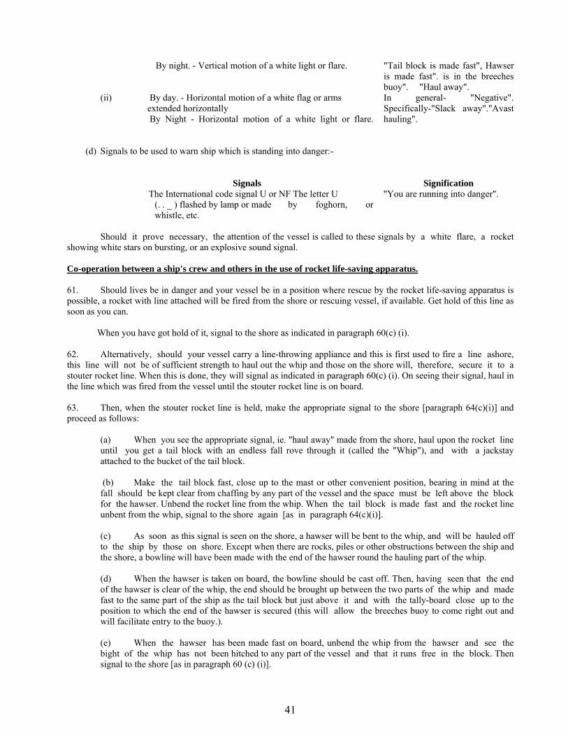
41
By night. - Vertical motion of a white light or flare. "Tail block is made fast", Hawser is made fast". is in the breeches buoy". "Haul away".
(ii) By day. - Horizontal motion of a white flag or arms extended horizontally By Night - Horizontal motion of a white light or flare.
In general- "Negative". Specifically-"Slack away"."Avast hauling".
(d) Signals to be used to warn ship which is standing into danger:-
Signals Signification The International code signal U or NF The letter U
(. . _ ) flashed by lamp or made by foghorn, or whistle, etc.
"You are running into danger".
Should it prove necessary, the attention of the vessel is called to these signals by a white flare, a rocket showing white stars on bursting, or an explosive sound signal. Co-operation between a ship's crew and others in the use of rocket life-saving apparatus. 61. Should lives be in danger and your vessel be in a position where rescue by the rocket life-saving apparatus is possible, a rocket with line attached will be fired from the shore or rescuing vessel, if available. Get hold of this line as soon as you can. When you have got hold of it, signal to the shore as indicated in paragraph 60(c) (i). 62. Alternatively, should your vessel carry a line-throwing appliance and this is first used to fire a line ashore, this line will not be of sufficient strength to haul out the whip and those on the shore will, therefore, secure it to a stouter rocket line. When this is done, they will signal as indicated in paragraph 60(c) (i). On seeing their signal, haul in the line which was fired from the vessel until the stouter rocket line is on board. 63. Then, when the stouter rocket line is held, make the appropriate signal to the shore [paragraph 64(c)(i)] and proceed as follows:
(a) When you see the appropriate signal, ie. "haul away" made from the shore, haul upon the rocket line until you get a tail block with an endless fall rove through it (called the "Whip"), and with a jackstay attached to the bucket of the tail block. (b) Make the tail block fast, close up to the mast or other convenient position, bearing in mind at the fall should be kept clear from chaffing by any part of the vessel and the space must be left above the block for the hawser. Unbend the rocket line from the whip. When the tail block is made fast and the rocket line unbent from the whip, signal to the shore again [as in paragraph 64(c)(i)]. (c) As soon as this signal is seen on the shore, a hawser will be bent to the whip, and will be hauled off to the ship by those on shore. Except when there are rocks, piles or other obstructions between the ship and the shore, a bowline will have been made with the end of the hawser round the hauling part of the whip. (d) When the hawser is taken on board, the bowline should be cast off. Then, having seen that the end of the hawser is clear of the whip, the end should be brought up between the two parts of the whip and made fast to the same part of the ship as the tail block but just above it and with the tally-board close up to the position to which the end of the hawser is secured (this will allow the breeches buoy to come right out and will facilitate entry to the buoy.). (e) When the hawser has been made fast on board, unbend the whip from the hawser and see the bight of the whip has not been hitched to any part of the vessel and that it runs free in the block. Then signal to the shore [as in paragraph 60 (c) (i)].

42
(f) The men on shore will then set the hawser taut, and by means of whip will haul off to the ship the breeches buoy into which the person to be hauled ashore is to get. He should sit well down in the breeches buoy and when he is secure, signal again to the shore as indicated in paragraph 64 (c) (i) above, and the men on shore will haul the person in the breeches buoy to the shore. When he is landed the empty breeches buoy will be hauled back to the ship. This operation will be repeated until all persons are landed. (g) During the course of the operations should it be necessary to signal, either from your ship to the shore, or from shore to ship, to "Slack away" or "Avast hauling" this should be done as indicated in paragraph 64 (c) (ii).
64. It may sometimes happen that the state of the weather and or the condition of the ship will not admit of a hawser being set up; in such cases a breeches buoy will be hauled off by the whip which will be used without hawser. 65. The system of signalling must be strictly followed. It should , however, be noted that the rescue operations as a whole will be greatly facilitated if signal communication (by semaphore or flashing lamp ) is established between the ship and the shore (or lifeboat). 66. All women, children, passengers and helpless persons should be landed before the crew of the vessel. Masters and crew of stranded vessels should bear in mind that success in landing them by the rocket life saving apparatus depends in a great measure, upon their own coolness and attention to the instructions laid down. Tankers - use of rocket line throwing apparatus. 67. It may be dangerous to attempt to establish communication by means of a rocket line throwing apparatus with an oil tanker, should that vessel be carrying petrol, spirit or other highly inflammable liquid. The assisting vessel should lie to WINDWARD of the tanker and before firing a rocket in her direction, ascertain whether it is safe to do so. 68. When a vessel in distress is carrying petrol, spirit or other highly inflammable liquid and is leaking, the following signals should be exhibited to show that it is dangerous to fire a line carrying rocket by reason of risk of ignition:- By day:- Flag B of the International Code of signals hoisted at the masthead. By night :- A red light hoisted at the masthead. When visibility is bad the above signals should be supplemented by the use of the following International Code of signal made in sound:- G U (_ _ . . . _ ) "It is not safe to fire a rocket." SAR ORGANISATION IN INDIA 69. Indian Coast Guard and SAR Responsibilities.
(a) Indian Coast Guard has been entrusted with the duties of providing Search and Rescue assistance to mariners, and protection to fisherman including assistance to them at sea while in distress and safety of life and property at sea. Related to SAR, the Coast Guard charter of duties include:-
(i) Providing protection to fishermen including assistance to them at sea when in distress. (ii) Safety of life and property at sea. (iii) Search and Rescue at sea. (iv) Enforcement of Maritime laws at sea.
(b) Definition of SAR. Search and Rescue comprises the search for, and the provision of aid to, persons, ships or other craft which are, or are feared to be, in distress or imminent danger. The Indian Coast Guard is responsible for coordinating, Search and Rescue in the Indian Maritime Search and Rescue Region.

43
With a focus on the humanitarian nature of work, the Indian Coast Guard cooperates with other agencies to develop and sponsor vital standards and recommendations on daily basis.
(c) Rescue Agencies. In addition to the resources available with the Coast Guard, ships/aircraft/crafts/shore based facilities with the following agencies would be requisitioned for carrying out SAR operations:-
(i) Indian Navy (ii) Indian Air Force (iii) DG Shipping (iv) Port Authorities (v) Shipping Corporation of India (vi) Director General Civil Aviation (vii) States/Central Fisheries Authorities (viii) Merchant Ships operating close to position distress (ix) Civil Authorities (x) Indian Meteorological Department (xi) INMCC Bangalore (xii) Department of Telecommunications (xiii) States/Central Customs Authorities (xiv) NIOT
(d) Point of Contact of SAR Board Members. The Points of contacts of the resources agencies for SAR requirements are placed at Appendix `D’.
70. Search and Rescue Regions.
(a) Search and Rescue Region is an area of defined dimensions, associated with an MRCC within which SAR services are provided. The Regional Air Navigation Plans (RANPs) promulgated by ICAO, depicts aeronautical SRRs and Global SAR Plan promulgated by IMO delineates Maritime SRR. The countries have agreed to accept SAR responsibility for an area, which composed of one or more aeronautical SRRs. Any SAR facility within the SRR should respond to all distress situations whenever and wherever it is capable of doing so. (b) The purpose of establishing an SRR, is to clearly define who has the primary responsibility for coordinating responses to distress situations in different area of the world, and to enable rapid distribution of distress alerts to the proper MRCC. It is also to ensure that the SAR services are provided at the earliest for that geographic area assumed by the country. (c) The Maritime SRR is generally harmonized with Aeronautical SRR in most areas, which therefore minimize confusion over, which authority has to be alerted, when a distress situation arises at and over a specific geographic position.
71. Indian SRR and SAR Organisation.
(a) On accession to the International Convention on Maritime Search and Rescue 1979, Indian Government has assumed the responsibility of providing SAR cover in Indian SRR with Director General Indian Cost Guard designated as National Maritime SAR Coordinating Authority (NMSARCA). There are three geographic areas/regions established in Indian SRR, for coordinating responses to both maritime and aviation related distress incidents. (b) The SRR (West) covers the SAR operations on the western seaboard. The SRR (East) covers Bay of Bengal including portions of Palk Bay and Gulf of Mannar. The SRR (A&N) covers the area adjacent to Andaman and Nicobar Islands.

44
(c) There are three Maritime Rescue Coordination Centres (MRCCs) defined in INSRR. The MRCC located at Mumbai covers the entire western seaboard of Indian SRR. The eastern seaboard is covered by MRCCs located at Chennai and Port Blair.
72. Maritime Rescue Coordination Centre in Indian SRR.
(a) The Maritime Rescue Coordination Centre (MRCC) is an operational facility, responsible for promoting efficient organisation of SAR services, and for coordinating the conduct of SAR operations within the SRR. The MRCC only coordinates and does not necessarily provide the SAR facilities in the applicable SRR. Aeronautical SAR responsibility is to be met by Airports Authority of India and Aeronautical SAR coordination is performed from aeronautical RCC. (b) There are three Maritime Rescue Coordination Centres (MRCCs) defined in ISRR. The MRCC located at Mumbai covers the entire western seaboard of Indian SRR. The Eastern seaboard is covered by MRCCs located at Chennai and Port Blair. The coordinates of the Indian SRRs associated with the respective MRCCs are as follows:-
(i) MRCC Mumbai. The Indian SRR (West) area covered by the MRCC Mumbai, is defined by the line joining the following coordinates and IBL.
21 00 N 068 15 E 12 00 N 063 00 E 12 00 N 060 00 E 06 00 S 060 00 E 06 00 S 068 00 E 00 00 S 068 00 E 08 00 N 073 00 E 06 10 N 077 20 E 08 08 N 077 20 E (ii) MRCC Chennai. The Indian SRR (East) area covered by the MRCC Chennai, is defined by the line joining the following coordinates and IBL. 08 08 N 077 20 E 06 10 N 077 20 E 06 00 N 078 00 E 10 00 N 080 00 E 10 00 N 082 00 E 07 15 N 088 30 E 15 20 N 088 30 E Coastal border between India and Bangladesh (iii) MRCC Port Blair. The Indian SRR (A&N) area covered by the MRCC Port Blair, is defined by the line joining the following coordinates and IBL. Coastal border between India and Bangladesh 15 20 N 088 30 E 07 15 N 088 30 E 06 00 N 092 00 E 06 00 N 097 32 E
Northwards of position of serial (v) given above and covering the areas outside limits of the designated areas of other littoral countries.
(c) National SAR Agency: Indian Coast Guard.
Address: Coast Guard Headquarters, National Stadium Complex, Purana Quila Road, New Delhi – 110 001, India
Tel: +91 11 23384934 Telefax: + 91 11 23383196 E-mail: [email protected]

45
Telephone +91 Fax + 91 Others Western Region MRCC Mumbai CGRHQ(West)
22 24388065 22 24316558 Inmarsat “C”(IOR) 441907210 Inmarsat “mM”(IOR) 762882349 E:mail : [email protected] [email protected] [email protected]
MRSC Porbandar 286 2242450 286 2214422 286 2247148 286 2244056
286 2210559 Inmarsat “C”(IOR) 441908210 E:mail : dhq1@ indiancoastguard.nic.in
MRSC Goa 832 2521051 832 2521718
832 2520584 Inmarsat “C”(IOR) 441900445 E:mail : dhq11@ indiancoastguard.nic.in
MRSC New Mangalore 824 2405262 824 2405267 Inmarsat “C”(IOR) 441908310 Inmarsat “M”(IOR) 641900710 Inmarsat “mM”(IOR) Voice 764443569 Inmarsat “mM”(IOR) Fax 764443570 Inmarsat “mM”(IOR) Data 764443571 E:mail : [email protected]
MRSC Kochi 484 2218969 484 2218460
484 2217164 Inmarsat “C”(IOR) 441907410 Inmarsat “M”(IOR) 641901110 Inmarsat “mM”(IOR) Voice 764907778 Inmarsat “mM”(IOR) Fax 764907779 E:mail : [email protected]
MRSSC Vadinar 2833 256560 2833 256223
02833 256560 Inmarsat “C”(IOR) 441900448 Inmarsat “mM”(IOR) Voice 762484114 Inmarsat “mM”(IOR) Fax 762484115 Inmarsat “mM”(IOR) Data 762484116 E:mail:[email protected]
MRSSC Okha 2892 262257 2892 263421 2892 263348
02892 263421 Inmarsat “C”(IOR) 441900446 Inmarsat “mM”(IOR) Voice 762484056 Inmarsat “mM”(IOR) Fax 762484057 Inmarsat “mM”(IOR) Data 762484058 E:mail : [email protected]
Eastern Region
MRCC Chennai CGRHQ(East)
44 23460405
44 25395018 Inmarsat “C”(IOR) 441922669 Inmarsat “M”(IOR) 641901410 E:mail :[email protected]
MRSC Haldia 3224 267755 3224 263407
3224 264541 Inmarsat “C”(IOR) 441901710 Inmarsat “mM”(IOR) Voice 762484198 Inmarsat “mM”(IOR) Fax 762484199 Inmarsat “mM”(IOR) Data 762484210 E:mail : [email protected]
MRSC Paradip 6722 223380 6722 223359
6722 220174 Inmarsat “C”(IOR) 441907710 Inmarsat “mM”(IOR) Voice 762882363 Inmarsat “mM”(IOR) Fax 762882364 Inmarsat “mM”(IOR) Data 762882365 E:mail : [email protected]
MRSC Vizag 891 2568875 891 2547266 891 2741060
891 2568879
Inmarsat “C”(IOR) 441907010 Inmarsat “M”(IOR) 641900410 Inmarsat “mM”(IOR) Voice 762882360 Inmarsat “mM”(IOR) Fax 762882361 Inmarsat “mM”(IOR) Data 762882362 E:mail : [email protected]

46
MRSC Tuticorin 461 2353503 461 2352046
461 2353503 Inmarsat “C”(IOR) 441900447 Inmarsat “mM”(IOR) Voice 762484086 Inmarsat “mM”(IOR) Fax 762484087 Inmarsat “mM”(IOR) Data 762484088 E:mail : [email protected]
MRSSC Mandapam 4573 241634 4573 241519
4573 241142
Inmarsat “C”(IOR) 441907810 Inmarsat “mM”(IOR) Voice 761887345 Inmarsat “mM”(IOR) Fax 761887346 Inmarsat “mM”(IOR) Data 761887347 E:mail : [email protected]
Andaman & Nicobar Region
MRCC Port Blair CGRHQ(A&N)
3192 232681 3192 242948 Inmarsat “C”(IOR) 441922666 Inmarsat “mM”(IOR) Voice 762483765 Inmarsat “mM”(IOR) Fax 762483766 Inmarsat “mM”(IOR) Data 762483767 E:mail : [email protected]
MRSC Diglipur 3192 271315 3192 232345
3192 272345 Inmarsat “C”(IOR) 441908110 Inmarsat “mM”(IOR) Voice 762483768 Inmarsat ”mM”(IOR) Fax 762483769 Inmarsat ”mM”(IOR) Data : 762483770 E:mail : [email protected]
MRSC Campbell Bay 3192 264015 3192 264215 Inmarsat “C”(IOR) 441907910 Inmarsat “mM”(IOR) Voice 762483771 Inmarsat ”mM”(IOR) Fax 762483772 Inmarsat ”mM”(IOR) Data : 762483773 E:mail : [email protected]
India MCC (INMCC) COSPAS-SARSAT SPOC
080 28094546
80 2837 1857
E:mail : [email protected] [email protected]
(d) Adjacent SRRs. The SRR of neighboring countries namely Pakistan, Maldives, Sri Lanka, Seychelles, Mauritius, Indonesia, Malaysia, Myanmar and Bangladesh share the boundary with Indian SRR. These SRR are established in cooperation with the neighbouring nations which are internationally recognized and described in the pertinent documents of IMO and Indian List of Radio Signals(ILRS) Vol 5, INP 31(5), Edition 2011. The coordinating authorities of the respective SRRs along with contact details are as mentioned below:-
(i) Pakistan SRR. Ports and Shipping wing of Ministry of Communication is responsible for coordinating Search and Rescue operations. MRCC Pakistan (Maritime Security Agency) is located at Karachi. Telephone : 00 92 21 9214624 00 92 21 9214964 – 67 00 92 21 9214865 Telefax : 00 92 9214625 00 92 9214621 Inmarsat “C” (IOR) : 446302810 E:mail : [email protected] (ii) Maldives SRR. Maldives Coast Guard is the National SAR Agency, MRCC located at Male. Telephone : 00 960 3325981 00 960 3338898 Telefax : 00 960 3310054
47
E:mail : [email protected] (iii) Sri Lanka SRR. SAR operations are coordinated with Sri Lankan Navy, Air force and Port Authorities under Deputy Director, Merchant Shipping, Ministry of Trade and Shipping. MRCC is located at Colombo. Telephone : 00 94 11 2623030 Telefax : 00 94 11 2424249 Telex : 00 803 23277 CLORDO CE E:mail : [email protected] (iv) Seychelles SRR. Seychelles Coast Guard with assistance of Port and Marine Services Division coordinates the SAR operations. The MRCC is located at Mahe, Seychelles.
Telephone : 00 248 224411 00 248 224616 Telefax : 00 248 323288 00 248 224665
E:mail : [email protected]
(v) Mauritius SRR. SAR operations in the SRR are coordinated by National Coast Guard. MRCC is located at Port Louis. Telephone : 00 230 2088317 00 230 2083935 00 230 2122747 Telefax : 00 230 2122757 00 230 2122770 Inmarsat “C” IOR : 464590210
(vi) Indonesia SRR. Baden SAR National is the SAR agency. Telephone : 00 21 3521111 00 21 34832901 Telefax : 00 21 34832884
E:mail : [email protected]
(vii) Malaysian SRR. Marine Department of Malaysia is responsible for SAR operations in their SRR. MRCC Malaysia at Port Kelang. Telephone : 00 60 3 89957000 Telefax : 00 60 3 89473601
E:mail : [email protected]
(viii) Myanmar SRR. SAR operations are coordinated between the Myanmar Air force and Navy, and the Department of Civil Aviation and Marine Administration. MRCC Yangon is located at Rangoon. Telephone : 00 95 1 202417 Telefax : 00 95 1 240630 E:mail : [email protected]
(ix) Bangladesh SRR. The Department of Shipping is responsible for coordinating SAR Operations. MRCC Dhaka located at Dhaka. Telephone : 00 880 2 407643 00 880 2 405434

48
Telefax : 00 880 2 9666159 00 880 2 7168363
E:mail : [email protected] Aircraft Assisting Ship 73. Aircraft used on search and rescue duties may be able to assist a ship in distress by:- (a) Locating her when her position is in doubt and informing the shore authorities so that ships in the
vicinity going to her assistance may be given her precise position; (b) Guiding surface craft to the casualty or, if the ship has been abandoned, to survivors in
lifeboats, or rafts at sea; (c) Keeping the casualty under observation; (d) Dropping a marine marker and a smoke float by day or a flame float at night to mark the position; (e) Dropping survival equipment. Ships in distress may be supplied with special items of droppable equipment by SAR aircraft. This may comprise equipment containers connected in series by a buoyant rope. Alternatively the following may be dropped:- (a) Individual life raft or pairs linked by a buoyant rope; (b) Buoyant radio beacons and/or trans-receivers; (c) Dye and smoke markers and flame floats; (d) Parachute flares for illumination; (e) Salvage pumps. 74. When a number of aircraft are engaged on a search for a casualty at sea, the procedure followed is to search an area which has been calculated to include the most probable position of the incident, allowing for any movement due to drift during the period of the search. The normal technique is for the aircraft to carry out 'creeping line ahead' searches for as long as the aircraft's endurance on task will permit. The spacing between the tracks flown by the aircraft depends on the visibility, the characteristics of the object being searched (e.g., dinghy, lifeboats, or raft etc. ) and the type, if any, of electronic search aid used.
(a) Maritime aircraft may be employed to search at night for ships/aircrafts known to be in distress or overdue, or for survivors in lifeboats or life raft. Unless distressed personnel are able and know how to indicate their position to the aircraft the search may be valueless and could result in failure to locate survivors and transfer of the search to another area. (b) The aircraft will fly through the search area at between three to five thousand feet or below cloud. The aircraft may switch on landing lights to indicate position.
(c) Points to note. (i) Each lifeboat or liferaft should carry at least three red flares. (ii) If all else fail, use any means at your disposal to attract attention.

49
Helicopter Operations With Merchant Ships 75. Limited facilities for Rescue by Helicopters are available in the immediate vicinity of the ports of Mumbai (Bombay), Goa, Kochi (Cochin), Vishakhapatnam and Port Blair. Some general information is given below:- Routine Use of Helicopter at Sea 76. Helicopter may operate from time to time with merchant ships at sea. These operations can be hazardous unless the following safety precautions are taken:-
(a) For helicopter winching, the ship must be steady on a course giving minimum ship roll & pitch motions. Relative wind should be maintained as follows:-
For Helicopter operating area Aft –30o on Port Bow. Midship - 30o from Port Bow or a beam wind . Forward - 30o from Starboard Quarter. If this is not possible the ship should remain stationary head to wind, or follow the instructions of the helicopter crew.
(b) An indication of relative wind direction should be given. to helicopter on R/T or Flags and pennants , illuminated at night could also indicate relative wind by the air flitter in wind. Smoke from a galley funnel may also give an indication of the wind but in all cases where any funnel is making exhaust, the wind must be at least two points off them port bow. (c) Clear as large an area of deck (or covered hatchway) as possible and mark the area with a yellow dot 5 meters in diameter. Whip or wire aerials, davits, flag staffs or any other obstruction in and around the area should, if at all possible, be struck down. (d) All loose articles must be securely tied down or removed from the transfer area. The downwash from the helicopter’s rotor will easily lift unsecured covers, tarpaulins, hoses, rope and gash, etc., thereby presenting a severe flying hazard. Even small pieces of paper, if ingested by a helicopter engine, can cause the helicopter to crash. (e) If a clear area cannot be provided, personnel can be lifted from a boat being towed astern of the ship by a long painter giving enough sea room to helicopter for hover. (f) On no account must the winch wire or load be allowed to foul any part of the ship or rigging. In the event of a load or wire becoming snagged, the helicopter crew will cut the winch wire. (g) The winch wire should be handled only by personnel wearing rubber gloves and solid rubber shoes. A helicopter can build up a charge of static electricity which if discharged through a person handling the winch wire, can kill or cause severe injury. The helicopter crew will normally discharge the static electricity before commencing the operation by dipping the winch wire in the sea or allowing the hook to touch the ship's deck. However, under some conditions sufficient static electricity can build up during the operation to give unprotected personnel a sever shock. (h) The helicopter will approach heading into the relative wind. For operating areas aft and midship the helicopter will approach from astern or abeam, and for operating area forward it will approach from the bow. The helicopter can lower on to or lift from the clear area (or boat towed astern ). The maximum length of winch cable is normally about 80 meters but may be only 15 meters in some cases. The helicopter must keep clear of any obstructions such as masts since any contact by them with either the main or tail rotor will be disastrous for the helicopter. (j) When being landed from a helicopter, personnel must obey the instructions given by the helicopter crew since there is a danger of inadvertently walking into the tail rotor which, due to its high speed of rotation, is difficult to see.

50
(k) EXTREME CAUTION must be exercised when firing line throwing rockets or any pyrotechnics when helicopter are in the vicinity.
Note:- If there are a number of survivors and there is a suitable clear area the pilot may wish to land on board. If so, he will discuss this option with the master before committing himself. Use of Helicopters at Sea for Rescue and Medical Evacuation 77. When a distress message is received either visually or by radio from a ship in distress, steps taken by the rescue authorities ashore may include asking the nearest Rescue Co-ordination Centre to dispatch a helicopter to assist in the rescue. 78. It is essential that the ship's position should be given as accurately as possible if the original distress signal is made by radio. The bearing (magnetic or true) and distance from a fixed object, like a headland or lighthouse, should be given if possible. The type of ship and colour of hull should be included if time allows. 79. Helicopters are fitted with VHF FM and AM, UHF and HF RT; they do not normally carry MF. Communication between ship and helicopter should normally be achieved on Marine Band VHF/FM, but 2182 kHz is also available. It may be possible to do so via a lifeboat if one is in the vicinity. Alternatively a message may be passed via a Coast Radio Station on 2182 kHz, or on VHF 121.5 MHz or 243 MHz. 80. Once the helicopter has become airborne, the speed with which it locates the ship and the effectiveness of its work depends to a large extent on the co-operation of the ship herself. 81. From the air, especially if there is a lot of shipping in the area, it is very difficult for the pilot of a helicopter to pick out the particular ship he is looking for from the many in sight, unless that ship uses distinctive distress signal which can be clearly seen by him. One such signal is the orange-coloured smoke signal carried in the lifeboats. This is very distinct from the air. A well trained Aldis lamp can also be seen except in very bright sunlight when the lifeboat heliograph could be used. The display of these signals will save valuable time in the helicopter locating the casualty, and may mean all the difference between success and failure. It is not suggested, of course, that the Aldis lamp need necessarily be used to pass message in Morse. 82. If from the ship in trouble it is observed that the helicopter is going to pass by, or is on a course which will take it away, continued use should be made of visual distress signals, and at the same time, if fitted with radio, the fact reported to the helicopter stating its present bearing and distance from the ship. Helo could be guided using clock codes to indicate position. 83. Wherever possible and if time allows, all the safety precautions mentioned in paragraph 92 should be taken. However, in a distress situation it may not be possible to meet all the requirements. Under such circumstances the operation may necessarily be slower than a routine operation but, because of their operational limitations, helicopters should not be unnecessarily delayed at the scene of rescue. Cases have arisen where the rescue has been seriously hampered by survivors trying to take personal belongings with them when being rescued by helicopter. In distress situations, transfers are limited to personnel only. 84. When co-operating with helicopters in SAR operations, ships should not attempt to provide a lee whilst helicopters are engaged in winching operations as this tends to create turbulence. 85. The helicopter pilot and crew are professionals in methods of rescue and well intentioned assistance from either the survivor himself or third parties in saving survivors invariably results in delays. The deck party should, therefore, remain stationary and allow the helicopter to move to them. The following rescue methods are employed:- (a) The survivor, whether on deck or in the water, is rescued by means of strop. Whenever possible the
crew is lowered from the helicopter together with the strop which is secured around the survivor's back and chest, and the survivor/casualty is winched up followed by the aircrew man.

51
(b) On certain occasions it may be necessary for the survivor to position the strop himself and proceed as follow:-
(i) Grasp the strop and put both arms and head through the loop. (ii) Ensure the wide padded part is as high as possible across the back, with the two straps
coming under the armpits and up infront of the face. (iii) Pull the toggel down as far as possible. (iv) When ready to be lifted, look up at the helicopter, put one arm out to full extent and give
a "thumbs up" and continue to look up for visual indications from the helicopter crew. (v) Spread arms horizontally, try and counter-act the swing should there be any. (vi) When just below the helicopter, try and ward off to avoid being hit by the helicopter bottom. (c) If a survivor on deck is injured to the extent that the use of a strop around his back and chest
would aggravate the injury or cause suffering, a crew is lowered on to the deck with the stretcher. The survivor is placed in the stretcher, strapped in such a manner that it is impossible for him to slip or fallout, and both stretcher and crew are winched up into the helicopter. If possible the helicopter will be carrying a doctor who will be lowered to the deck and will assist the survivors as necessary. If the patient is already in a Neil - Robertson type stretcher this can either be lifted straight into the aircraft or placed in the rigid frame stretcher. It may also be possible to land the crew with a portable radio for direct communication with the helicopter.
86. When being landed from a helicopter, personnel must obey the instructions given by the helicopter crew since there is a danger of inadvertently walking into the tail rotor which, due to its high speed of rotation, is difficult to see.
AIRCRAFT CASUALTIES AT SEA Distress Communication 87. Visual signals. An aircraft may indicate it is in distress by firing a succession of red pyrotechnic lights, by signalling SOS with signalling apparatus or by firing a parachute flare showing a red light. Navigation markers dropped by aircraft at sea, emitting smoke, or flames and smoke, should not be mistaken for distress signals. Low flying is not in itself an indication of distress. 88. An aircraft which has located another aircraft in distress may notify ships in the vicinity by passing a massage in plain language on distress frequencies. It may also give the following signals, together or separately, to attract a ships attention:- (a) the repeated switching on and off of the aircraft's landing lights (b) the irregular repeated switching on and off of the aircraft's navigational lights. If it wishes to guide a ship to the casualty or survivors it will fly low around the ship or cross the projected course of the ship close ahead at a low altitude opening and closing the throttle or changing the propeller pitch. It will then fly off in the direction in which the ship is to be led. Pilots are instructed to rock their aircraft laterally when flying off in the direction of the casualty. The ship should acknowledge receipt of the signal and of messages on the same radio frequency. It should then either follow the aircraft or indicate by visual or radio means that it is unable to comply. The procedure for canceling these instructions is for the aircraft to cross the wake of the surface craft close astern at a low altitude, rocking the wings or opening and closing the throttle or changing the propeller pitch. 89. In order to take advantage of the greater visibility of pyrotechnics at night, searching aircraft will fly a creeping-line-ahead type of search, watching for a distress signal/pyrotechnic from the survivor(s). 90. Survivors from crashed aircraft in rubber liferafts may give the following visual distress signals:-
(a) Fire pyrotechnic signals emitting one or more red stars, or orange/red smoke.

52
(b) Flash a heliograph
(c) Flash SOS or other distinctive signal by hand torch or other signaling lamp. Some life raft may show a steady or a flashing light.
(d) Blow whistles.
(e) Use of fluorescent dye marker giving an extensive bright green colour to the sea around the survivors.
(f) Fly a yellow kite from the life raft to support the aerial for the emergency radio transmitter. 91. Radio Signals. Radio if, an aircraft transmits a distress message by radio, the first transmission is made on the designated Air/Ground Route frequency in use at the time between the aircraft and the appropriate ground station, normally an Air Traffic Control Centre (A.T.C.C.). The aircraft might be asked by the A.T.C.C. to change to another frequency, possibly on another H.F. Route frequency or on the International aeronautical emergency frequency of 121.5 MHz or 243.0 MHz. If the aircraft is unable to contact the ground station on the route frequency, any other available frequency may be used in an effort to establish contact with any land, mobile or direction finder station. 92. There is close liaison among shore stations, including Air Traffic Control Centres, Rescue Co-ordination Centres, and the Indian Coast Guard. Merchant ships will ordinarily be informed of aircraft casualties at sea by broadcast messages made on the International distress frequencies of 500 kHz, 2182kHz and VHF Ch 16. Ships may, however, become aware of the casualty by:-
(a) picking up an SOS message from an aircraft in distress which is able to transmit on 500 kHz or by intercepting a distress signal from an aircraft using radiotelephony on 2182 Khz or VHF Ch 16.
(The form of such messages is given in Appendix B);
(b) Hearing and able to DF on the radio transmission on 500 Khz, 121.5 MHz and 243.0 MHz from the hand-operated emergency transmitter carried by survival life rafts. (The form of such signal is given in Appendix B),or
(c) Picking up a message from a search and rescue aircraft. 93. If time permits the aircraft shall also transmit the distress call and message on the following frequencies:
(a) If over open sea on 2182 or 8346 kHz. In addition and if time permits and the aircraft is so equipped the distress call is made on the International Distress frequency 500 kHz.
(b) If over land on the European Continent or within range of a communication station elsewhere, VHF/RT frequency of 121.5 MHz. This is also the frequency of SARBE & TALBE equipment.The distress message from the aircraft will contain as much of the following information as time permits:-
(i) Estimated position and time of the distress; (ii) Heading in degrees (Magnetic and True); (iii) Indicated air speed; (iv) Flight level/altitude; (v) Nature of distress and type of assistance required; (vi) Type of aircraft; (vii) Intention of pilot; (viii) Endurance remaining; (ix) Any other information (e.g. ditching, etc.) Immediately before ditching of an aircraft as well as before total abandonment of an aircraft, the radio apparatus would be continuously on, if considered necessary and circumstances permit. A ship on receipt of a distress message shall transmit a report in the form given in Appendix 'C'.

53
Action to be Taken When an Aircraft is Forced to "Ditch" (Alight On The Sea) 94. The captain of a distressed aircraft will be materially assisted in locating a ship if the latter:-
(a) Transmits homing bearing to the aircraft, or (if so requested) transmits signals enabling the aircraft to take its own bearing ;
(b) By day makes black smoke; (c) By night directs a searchlight vertically. 95. Ditching an aircraft is difficult and usually dangerous. A ship which knows that an aircraft intends to ditch should, if practicable, try to provide a lee of calm water. This may be achieved by any means at the master's discretion, such as steering on a circular course through 360 degrees, with the addition, if possible, of an oil "slick". 96. The Captain of an aircraft normally sits on port side of the cockpit, and thus has better visibility on that side. An aircraft will therefore usually ditch on the starboard side of a ship and heading into wind, although, when seas are running high, it may be expected to attempt to land along the trough of the seas. In the absence of a pre-arranged plan, the ship should steam into wind and assume that the aircraft will ditch on her starboard side. Helicopter captains its on the starboard side of the aircraft and would, therefore normally ditch on the port side of the ship heading into wind. 97. If it is dark, the ship should illuminate the sea as much as possible by searchlight on the side upon which the aircraft is expected to ditch. Care should be taken not to dazzle the pilot who might otherwise lose control of his aircraft at a critical moment. It will help the pilot considerably if flame floats or preferably, in view of the danger of petrol coming into contact with them, battery operated floats are laid line astern to indicate the direction of the suggested alighting area. Six floats should be laid at 200 yards (182.9m) intervals. 98. The ship's Master should, if possible, tell the captain of an aircraft which is going to ditch the general weather conditions, including wind speed and direction, visibility, state of sea and swell, approximate cloud base and barometric pressure. 99. A land plane may break up immediately on striking the water, and life rafts may be damaged. The ship should therefore have a lifeboat ready for launching and, if possible, boarding nets should be lowered from the ship and heaving lines made ready in the ship and the lifeboat. Survivors of the aircraft may have orange lifejackets, water torch and whistles. 100. The method of picking up survivors from life raft must be left to the judgment of the captain of the ship carrying out the rescue operation. 101. The drift rate of a life raft would normally be expected to exceed that of a ship, so that with the ship to windward, the life raft might drift away from the ship unless some suitable means were available to catch the life raft and hold it alongside. This might involve the ship having to repeat the whole procedure of coming alongside again. However, if the ship were stopped long enough for her full drift rate to develop, this rate should exceed that of the life raft which would decrease as the lee afforded by the ship increased. On the other hand, ships of low freeboard would not afford much protection in any sea way, and the drift rate of the life raft might not be arrested, and heavy seas washing over the lee side would make it difficult to take survivors on board. Another point to be considered is the lack of maneuverability once a ship is stopped. 102. With the ship to leeward, there should be no difficulty in keeping the life raft alongside, but with heavy seas running, there is the risk of life raft being dashed against the ship's side, and greater difficulty in taking survivors onboard. 103. It should be borne in mind that Military aircraft are often fitted with ejection seat mechanism, the position of which is indicated by a red solid triangle. The mechanism is activated by black and yellow striped handles. All handles or knobs, switches, etc., coloured red and with black and yellow stripes should not be touched, as the consequences of so during assistance may cause injury or even fatal injury to both the rescuer and the rescued.

54
Action taken to render assistance. 104. All information concerning aircraft in distress at sea or overdue in water surrounding India is passed to the Sector Search and Rescue Co-ordination Centre in whose area of responsibility the casualty has occurred or is likely to occur. Aircraft will then be sent, if necessary and practicable, to search for and fix as accurately as possible the position of the casualty. Although these aircraft will carry droppable survival equipment the survivors may normally be rescued by naval and merchant ships. 105. When an aircraft ditches into water, the first duty of any rescue craft is to save all persons aboard the aircraft, which may sink quickly. Ships making for an aircraft in distress should steam at full speed. The occupants may, however, be unconscious and either trapped within the aircraft or entangle in the wreckage. Passengers and crew are secured to their seats by webbing harness which passes over their shoulders, or by leather belts around their waists; these have quick release buckles, but it is simpler to cut them with a knife. If the ditched aircraft is on fire, the water surrounding it will probably be covered with burning petrol. Anyone thrown clear and floating in the fringes of the fire may be rescued by a grapnel with chain. The wreckage may be of great utility in determining the cause of an accident. Any attempt of salvage should be done with great care and keeping in view the hazards involved. 106. Every endeavour will be made to give merchant ships an accurate position of the casualty. When giving such a fix the ship should at once consult any other ship in the neighbourhood on the best procedure to be adopted, as is the practice in the case of casualties to ship; the ship going to rescue should answer the station sending the broadcast and give her identity, position and intended action. 107. If a merchant ship picks up an SOS message direct from the aircraft in distress, she should act as indicated in the preceding para and also relay the message to the nearest Coast Radio Station. Moreover, a merchant ship which has received an SOS message direct from the aircraft in distress and is going out to the rescue should take a bearing on the transmission and inform the Coast Radio Station or other vessel in the vicinity of the call-signal of the distressed aircraft the time at which the distress message was received, followed by the bearing and time at which the signal ceased. Action to be taken when survivors are picked up. 108. A survivor from an aircraft casualty at sea who is picked up by a ship may be able to provide information which will assist in the rescue of other survivors. Master are therefore asked to put the following questions to rescued survivors of an aircraft casualty and to communicate the answers to a Coast Radio Station. They should also give the position of the rescuing vessel and the time when the survivors was picked up.
(a) Did you bale out or was the aircraft ditched? What was the time and date? (b) If you have bailed out, at what altitude? (c) How many others did you see leave the aircraft by parachute? (d) How many ditched with aircraft? (e) How many did you see leave the aircraft after ditching? (f) How many survivors did you see in the water? (g) What floatation gear had they? (h) What was the total number of persons aboard the aircraft prior to the accident? (i) What caused the emergency?
Masters are reminded that survivors may, especially in colder climates, be suffering from .lm 1.0" hypothermia and that qualified medical advice should be provided at the earliest opportunity.
55
109. SEARCH AND RESCUE SIGNALS (Extract from I.C.A.O. Annex. 12 Chapter VI)
(a) Signals with surface craft. - When it is necessary for an aircraft to direct a surface craft to the place where an aircraft or surface craft is in distress the aircraft shall do so by transmitting precise instructions by any means at its disposal. If such precise instructions cannot be transmitted or when necessary for any other reason the instructions shall be given by using the procedure prescribed in sub -paragraph (b) below. NOTE: - Current maritime signalling procedures include: For Acknowledging Receipt of Signals (i) the hoisting of a "Code pennant" (vertical red and white stripes) close up (meaning
understood); (ii) the flashing of a succession of "Ts" by signal lamp in Morse Code; (iii) the changing of heading. For Indicating Inability to Comply (iv) the hoisting of the international Code flag "N" (a blue and white chequered square); (v) the flashing of a succession of "Ns" in Morse code. (b) The following procedures performed in sequence by an aircraft shall mean that the aircraft is
directing a surface craft towards an aircraft or a surface craft in distress:- (i) Circling the surface craft at least once; (ii) Crossing the projected course of the surface craft ahead at a low altitude opening and closing
the throttle or changing the pitch; (i) Heading in the direction in which the surface craft is to be directed.
Repetition of such procedure shall have the same meaning.
(c) The following procedure performed by an aircraft shall mean that assistance of the surface craft to
which the signal is directed is no longer required:- (i) Crossing the wake of the surface craft close astern at low altitude, opening and closing the
throttle or changing the propeller pitch.

56
Appendix 'A' (Refers to Para 20)
FORM OF DISTRESS MESSAGE FROM A LIFERAFT EMERGENCY TRANSMITTER ON 500 kHz
1. The emergency radiotelegraph transmitter is fitted with an automatic keying device to transmit repeatedly one of the following signals:- (a) S O S followed by a 20-second dash. This will normally +be sent and it enables ships to take
bearings.
(b) S O S preceded by a series of four second dashes at one-second intervals. This operates ships' automatic distress warning alarms.
2. Alternatively, the hand keying switch may be used to transmit other messages in morse code.

57
Appendix 'B' (Refers to Para 92)
FORM OF DISTRESS CALLS AND MESSAGE FROM AIRCRAFT
1. The exact form of distress call or message from an aircraft in flight will depend on the time available to send it between the onset of the emergency and the landing of the aircraft in the sea. This may be matter of seconds. 2. When time permits, the form of distress call and distress message sent by civil aircraft will be as follows:- (a) Distress Call By radiotelephony. the distress signal MAYDAY spoken three times. -- the word THIS IS -- the identification of the aircraft in distress spoken three times. -- the radio frequency used in the transmission of the distress call. (b) Distress Message (i) the distress call (sent once); (ii) the call sign or identification of the aircraft in distress, and as much as possible of the
following information; (iii) nature of distress and kind of assistance required; (iv) position, time of position and height, heading (magnetic and true) and indicated air
speed (in knots). (v) any other information which might facilitate the rescue (including the intention of the
person in command, e.g., ditching). Note:- "Heading" gives the direction of the aircraft in the air, the speed and direction of the aircraft in the air, the speed and direction of the wind have to be allowed for to ascertain the actual direction over the sea. "Indicated air speed" does not give the speed of the aircraft over the water as it does not allow, amongst other things, for the effect of the wind or the correction that has to be made for height. 3. If the circumstances make it necessary, the distress message may be sent without transmitting a prior distress call. 4. The distress message will be followed immediately:
By transmission of unmodulated carrier wave for two periods of about ten seconds each, the call sign of the aircraft once and the word "OVER".
5. If the aircraft is to be ditched, the radio transmitter may be set for continuous transmission immediately prior to ditching, if circumstances permit. Examples of Distress call and Message sent by radiotelegraphy:- Distress Call “SOS SOS SOS DE GABCD GABCD GABCD" Distress Message “SOS GABCD ENGINE FAILURE QTH 1820 NORTH 6830 EAST QAH 8000 FT QTL 090 QTJ 250 QUG" The signals QTH, QTL, QTJ and QUG (denoting position, true heading, indicated airspeed and that the aircraft is to be ditched respectively) are taken from the General Section of the Q Code. The signal QAH,is taken from the Aeronautical Section of the Q Code and signifies the aircraft's altitude. 7. Civil aircraft using radiotelephony will use one of the following four types of call sign;
(a) a five character call sign, e.g. GABCD,4XABC. (b) a code word denoting the aircraft operating company followed by the flight number of the

58
service on which the aircraft is operating , e.g., CLIPPER256 (CLIPPER is the code word denoting Pan Airways).
(c) a code word denoting the aircraft operating company followed by a five character call sign, e.g., BEALINE GABCED (BEALINE is the code word denoting British Airways [European Division].
(d) a combination of characters corresponding to the official registration mark of the aircraft, e.g., N3578.
The types of call signs in (b) and (c) are those most generally used. After communication has been established when using the type of call sign in (c) an abridged call sign consisting of the airline code word and the last two characters of the five-letter call sign may be used, e.g., BEALINE CD. 8. The following pronunciation is used when transmitting numerals:
Numeral/ Pronunciation Numeral/ Pronunciation numeral numeral element element 0 ZE-RO 7 SEv-en 1 WUN 8 AIT 2 TOO 9 NINE-er 3 TREE 4 FOW-er 5 FIFE Decimal DAY-SE-MAL 6 SIX Thousand Thousand (The syllable shown in capital letters is stressed)
9. In radiotelephony all numbers are transmitted by pronouncing each digit separately, except that the whole thousands are transmitted by pronouncing each digit in the number of thousands followed by the word "THOUSAND":- e.g.,969 is spoken as "Nine six nine" 1,986 is spoken as "One nine eight nine" 16,000 is spoken as "One six thousand" 10. The phonetic alphabet which is used with the English pronunciation is as follows:-
Letter Word Pronunciation Letter Word Pronunciation in English in English A Alfa AL FAH N November NO VEM BER B Bravo BRAH VOH O Oscar OSS CAH C Charlie CHAR LEE P Papa PAH PAH D Delta DELL TAH Q Quebec KEH BECK E Echo ECK OH R Romeo ROW MEOH F Foxtrot FOK STROT S Sierra SEE AIR RAH G Golf GOLF T Tango TANG GO H Hotel HOHTELL U Uniform YOUNE FORM I India IN DEE AH V Victor VIK TAH J Juliet JEW LEE ETT W Whiskey WISS KEY K Kilo KEY LOH X X-ray ECKS RAY L Lima LEE MAH Y Yankee YANG KEY M Mike MIKE Z Zulu ZOO LOO (The syllable to be emphasised are in bold letters)
11. The following is an example of a Distress Call and Distress Message transmitted by radiotelephony:-

59
Distress Call "MAYDAY MAYDAY MAYDAY THIS IS BEALINE GABCD BEALINE GABCD BEALINE GABCED"
Distress Message "MAYDAY BEALINE GABCD ENGINE FAILURE MY POSITION ONE
EIGHT TWO ZERO NORTH SIX EIGHT THREE ZERO EAST AT EIGHT THOUSAND FEET TRUE HEADING ZERO NINE ZERO TWO FIVE ZERO KNOTS WILL HAVE TO DITCH"
FORM OF URGENCY MESSAGE FROM AIRCRAFT Urgency message are originated when an aircraft is in danger and is in very urgent need of assistance which may possibly overcome the danger, e.g., aircraft lost, fuel shortage, partial failure and so on. Urgency call is as follows:- (i) (R/T VOICE) "PAN PAN PAN PAN PAN PAN aircraft callsign (Once)"
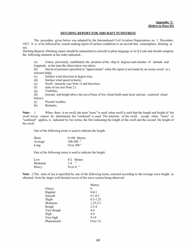
60
Appendix 'C' (Refers to Para 93)
DITCHING REPORT FOR AIRCRAFT IN DISTRESS
The procedure given below was adopted by the International Civil Aviation Organisation, on 1 December, 1957. It is to be followed by vessels making report of surface conditions to an aircraft that contemplates ditching at sea. Ditching Reports:-Ditching report should be transmitted to aircraft in plain language or in Q Code and should comprise the following elements in the order indicated:- (a) Unless previously established, the position of the ship in degrees and minutes of latitude and
longitude, at the time the observation was taken; (b) Sea-level pressure (specified as "approximate" when the report is not made by an ocean vessel or a
selected ship); (c) Surface wind direction in degree true; (d) Surface wind speed in knots; (e) Swell - intensity (see Note 1) and direction; (f) state of sea (see Note 2.) (g) Visibility;
(h) Amount and height above the sea of base of low cloud (both main layer and any scattered cloud below);
(j) Present weather; (k) Remarks. Note:- 1. When there is no swell, the term "none" is used; when swell is such that the length and height of the swell waves cannot be determined, the "confused" is used. The intensity of the swell, except when "none" or "confused" applies, is indicated by two terms, the first indicating the length of the swell and the second the height of the swell. One of the following terms is used to indicate the length: Short 0-100 Meters Average 100-200 " Long Over 200 " One of the following terms is used to indicate the height: Low 0-2 Meters
Moderate 2-4 " Heavy Over 4 " Note:- 2.The state of sea is specified by one of the following terms, selected according to the average wave height as obtained from the larger well-formed waves of the wave system being observed: Metres Glassy 0 Rippled 0-0.1 Smooth 0.1-0.5 Slight 0.5-1.25 Moderate 1.25-2.5 Rough 2.5-4 Very Rough 4-6 High 6-9 Very high 9-14 Phenomenal Over 14
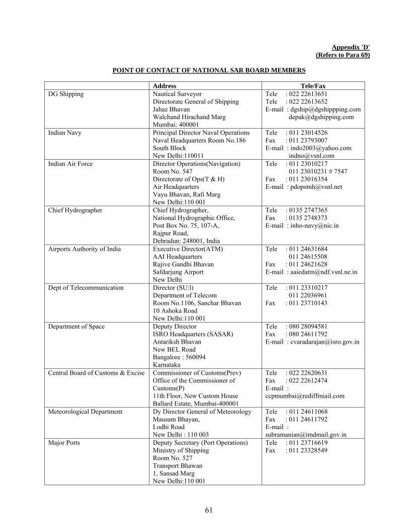
61
Appendix 'D' (Refers to Para 69)
POINT OF CONTACT OF NATIONAL SAR BOARD MEMBERS
Address Tele/Fax DG Shipping Nautical Surveyor
Directorate General of Shipping Jahaz Bhavan Walchand Hirachand Marg Mumbai: 400001
Tele : 022 22613651 Tele : 022 22613652 E-mail : [email protected] [email protected]
Indian Navy Principal Director Naval Operations Naval Headquarters Room No.186 South Block New Delhi:110011
Tele : 011 23014526 Fax : 011 23793007 E-mail : [email protected] [email protected]
Indian Air Force Director Operations(Navigation) Room No. 547 Directorate of Ops(T & H) Air Headquarters Vayu Bhavan, Rafi Marg New Delhi:110 001
Tele : 011 23010217 011 23010231 # 7547 Fax : 011 23016354 E-mail : [email protected]
Chief Hydrographer Chief Hydrographer, National Hydrographic Office, Post Box No. 75, 107-A, Rajpur Road, Dehradun: 248001, India
Tele : 0135 2747365 Fax : 0135 2748373 E-mail : [email protected]
Airports Authority of India Executive Director(ATM) AAI Headquarters Rajive Gandhi Bhavan Safdarjung Airport New Delhi
Tele : 011 24631684 011 24615508 Fax : 011 24621628 E-mail : [email protected]
Dept of Telecommunication Director (SU:l) Department of Telecom Room No.1106, Sanchar Bhavan 10 Ashoka Road New Delhi:110 001
Tele : 011 23310217 011 22036961 Fax : 011 23710143
Department of Space Deputy Director ISRO Headquarters (SASAR) Antariksh Bhavan New BEL Road Bangalore : 560094 Karnataka
Tele : 080 28094581 Fax : 080 24611792 E-mail : [email protected]
Central Board of Customs & Excise Commissioner of Customs(Prev) Office of the Commissioner of Customs(P) 11th Floor, New Custom House Ballard Estate, Mumbai-400001
Tele : 022 22620631 Fax : 022 22612474 E-mail : [email protected]
Meteorological Department Dy Director General of Meteorology Mausam Bhayan, Lodhi Road New Delhi : 110 003
Tele : 011 24611068 Fax : 011 24611792 E-mail : [email protected]
Major Ports Deputy Secretary (Port Operations) Ministry of Shipping Room No. 527 Transport Bhawan 1, Sansad Marg New Delhi:110 001
Tele : 011 23716619 Fax : 011 23328549
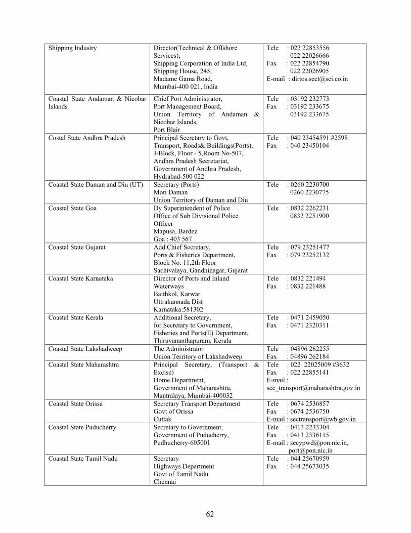
62
Shipping Industry Director(Technical & Offshore Services), Shipping Corporation of India Ltd, Shipping House, 245, Madame Gama Road, Mumbai-400 021, India
Tele : 022 22853556 022 22026666 Fax : 022 22854790 022 22026905 E-mail : [email protected]
Coastal State Andaman & Nicobar Islands
Chief Port Administrator, Port Management Board, Union Territory of Andaman & Nicobar Islands, Port Blair
Tele : 03192 232773 Fax : 03192 233675 03192 233675
Costal State Andhra Pradesh Principal Secretary to Govt, Transport, Roads& Buildings(Ports), J-Block, Floor - 5,Room No-507, Andhra Pradesh Secretariat, Government of Andhra Pradesh, Hydrabad-500 022
Tele : 040 23454591 #2598 Fax : 040 23450104
Coastal State Daman and Diu (UT) Secretary (Ports) Moti Daman Union Territory of Daman and Diu
Tele : 0260 2230700 0260 2230775
Coastal State Goa Dy Superintendent of Police Office of Sub Divisional Police Officer Mapusa, Bardez Goa : 403 567
Tele : 0832 2262231 0832 2251900
Coastal State Gujarat Add.Chief Secretary, Ports & Fisheries Department, Block No. 11,2th Floor Sachivalaya, Gandhinagar, Gujarat
Tele : 079 23251477 Fax : 079 23252132
Coastal State Karnataka Director of Ports and Inland Waterways Baithkol, Karwar Uttrakannada Dist Karnataka:581302
Tele : 0832 221494 Fax : 0832 221488
Coastal State Kerala Additional Secretary, for Secretary to Government, Fisheries and Ports(E) Department, Thiruvananthapuram, Kerala
Tele : 0471 2459050 Fax : 0471 2320311
Coastal State Lakshadweep The Administrator Union Territory of Lakshadweep
Tele : 04896 262255 Fax : 04896 262184
Coastal State Maharashtra Principal Secretary, (Transport & Excise) Home Department, Government of Maharashtra, Mantralaya, Mumbai-400032
Tele : 022 22025009 #3632 Fax : 022 22855141 E-mail : [email protected]
Coastal State Orissa Secretary Transport Department Govt of Orissa Cuttak
Tele : 0674 2536857 Fax : 0674 2536750 E-mail : [email protected]
Coastal State Puducherry Secretary to Government, Government of Puducherry, Pudhucherry-605001
Tele : 0413 2233304 Fax : 0413 2336115 E-mail : [email protected], [email protected]
Coastal State Tamil Nadu
Secretary Highways Department Govt of Tamil Nadu Chennai
Tele : 044 25670959 Fax : 044 25673035

63
Coastal State West Bengal Secretary (Transport), Government of West Bengal, Writers Building, Calcutta-700001
Tele : 033 2214 5455 Fax : 033 2214 4700
Fishing Community The Secretary National Fish Workers Forum 20/4 Sil Lane Kolkatta : 700015
Tele : 033 23297662 Fax : 033 23283989
Sailing Vessel Operators President, Federation of all Indian Sailing Vessel Industry Association C/o Hotel President Teen Batti, Near Town Hall Jamnagar:361001, Gujarat
Tele : 0288 2557491 Tele : 0288 22558491 E-mail : [email protected]
DGCA Director Ops (Aero) C/O Directorate of Civil Aviation Technical Centre Opp Safdarjung Airport New Delhi:110 003
Tele : 011 24641435 Fax : 011 24652760 E-mail : [email protected]
Department of Immigration The Director Burreau of Immigration C/o Ministry of Home Affairs New Delhi :110001
Tele :011 23389286 Fax :011 23383888 011 23385081

64
CONTACT DETAILS OF RESOURCES AGENCIES Agency Telephone No Fax No
Indian Coast Guard NMSARCA, New Delhi 011 23384934 011 23383196 MRCC, Mumbai 022 24316558
022 24388065 022 24316558 022 24333727
MRSC Porbandar 0286 2240958 0286 2210859 MRSC Goa 0832 2521051
0832 2521718 0832 2520584
MRSC New Mangalore 0824 2405262 0824 2405267 MRSC Kochi 0484 2218969
0484 2218460 0484 2217164
MRSSC Vadinar 02833 256579 02833 256560 MRSSC Okha 02892 262257
02892 263421 02892 263421
MRCC Chennai 044 23460405
044 25395018 044 25390405
MRSC Vishakapatnam 0891 2568879 0891 2568875 MRSC Paradip 06722 223380 06722 22712 MRSC Haldia 03224 267755
03224 263407 03224 264541
MRSC Tuticorin 0461 2352567 0461 2353503 MRSSC Mandapam 04573 241518
04573 241718 04573 241519
MRCC Port Blair 03192 245530 03192 242948 MRSC Diglipur 03192 272423 03192 272345 MRSC Campbell Bay 03192 264215 03192 264205
Indian Navy MOC (Delhi) 011 23010143 011 23792007 MOC (Mumbai) 022 22703743 022 22661702 MOC (Kochi) 0484 2662466
0484 2662793 0484 2668717 0484 2668257
MOC (Chennai) 044 25394240 044 25391286 044 25361999
MOC (Vishakhapatnam) 0891 2577240 0891 2577147 MOC (Port Blair) 03192 232785 03192 232785
Indian Air Force IAF Headquarters 011 23376500
011 23014729 011 23792973
IAF Mumbai 022 22054451 022 22059403 IAF Chennai 044 2375556
DG Shipping 022 22613651 022 22613654 022 22616140 022 22654256
022 22613655
Chief Hydrographer, GOI 0135 2744873 0135 2748373 Airport Authority of India 011 24631684
011 24615508 011 224611078
INMCC, Bangalore 080 28094546 080 28371857
080 28371857
Department of Telecom 011 23036658 011 23710143 Chairman, Major Ports
Chennai 044 25362201-20 044 25361228
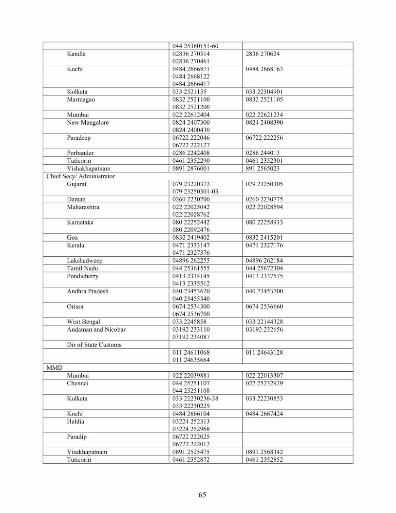
65
044 25360151-60 Kandla 02836 270514
02836 270461 2836 270624
Kochi 0484 2666871 0484 2668122 0484 2666417
0484 2668163
Kolkata 033 2521155 033 22304901 Marmagao 0832 2521100
0832 2521200 0832 2521105
Mumbai 022 22612404 022 22621234 New Mangalore 0824 2407300
0824 2400430 0824 2408390
Paradeep 06722 222046 06722 222127
06722 222256
Porbander 0286 2242408 0286 244013 Tuticorin 0461 2352290 0461 2352301 Vishakhapatnam 0891 2876001 891 2565023
Chief Secy/ Administrator Gujarat 079 23220372
079 23250301-03 079 23250305
Daman 0260 2230700 0260 2230775 Maharashtra 022 22025042
022 22028762 022 22028594
Karnataka 080 22252442 080 22092476
080 22258913
Goa 0832 2419402 0832 2415201 Kerala 0471 2333147
0471 2327376 0471 2327176
Lakshadweep 04896 262255 04896 262184 Tamil Nadu 044 25361555 044 25672304 Pondicherry 0413 2334145
0413 2335512 0413 2337575
Andhra Pradesh 040 23453620 040 23455340
040 23453700
Orissa 0674 2534300 0674 2536700
0674 2536660
West Bengal 033 2245858 033 22144328 Andaman and Nicobar 03192 233110
03192 234087 03192 232656
Dir of State Customs 011 24611068 011 24635664
011 24643128
MMD Mumbai 022 22039881 022 22013307 Chennai 044 25251107
044 25251108 022 25232929
Kolkata 033 22230236-38 033 22230229
033 22230853
Kochi 0484 2666104 0484 2667424 Haldia 03224 252313
03224 252968
Paradip 06722 222025 06722 222012
Visakhapatnam 0891 2525475 0891 2568342 Tuticorin 0461 2352872 0461 2352852

66
Goa 0832 2520617 0832 2520739 Port Blair 03192 232530 03192 234830
ONGC 011 23301000 011 23310156 011 23721756
011 23316413
Dredging Corporation of India 0891 2871230 0891 2871278

67
Special Notice No. 8: SHIP REPORTING SYSTEM – THE INDIAN SHIP POSITION AND INFORMATION REPORTING SYSTEM (INSPIRES) Source: Indian Coast Guard, Director General of Shipping (Govt. of India).
1. In order to exercise effective open ocean vessel management for security of vessels navigating along the Indian coast, the Indian Navy in coordination with Directorate General of Shipping established the Indian Ship Position and Information Reporting System (INSPIRES) with effect from 01 November 1986. All Indian merchant vessels including coastal vessels and fishing vessels of more than 300 GRT shall participate in this reporting system. All vessels other than Indian ship of tonnage 100 GRT and above are encouraged to participate in this system. In addition, all vessels above 100GRT, carrying dangerous and hazardous cargo transiting through the EEZ of India are also required to report their position as elaborated in para 5. 2. Objectives. Its main objective is 'Open Ocean Vessel Management'. The other objectives are as under:- (a) Security of maritime traffic within the assigned INSPIRES area;
(b) For effective vessel traffic management services;
(c) For weather forecasting to enhance safety of navigation
(d) Monitoring and prevention of marine pollution.
3. Area of Applicability (INSPIRES Area). The area of applicability of INSPIRES coincides with the limits of NAVAREA VIII as specified in the IMO Manual on Maritime Safety Information as follows:- (a) India /Pakistan frontier on coast (f) 300 S, 550 E (b) 120 N, 630E (g) 300 S, 950 E (c) 120 N, Somalian coast (h) 60 N, 95° E (d) 100 30’S, Tanzania coast (j) 100 N, Myanmar/Thailand Frontier (e) 100 30’S, 550E 4. Operating Authority. The Director General Shipping shall co-ordinate the functioning of the system with Maritime Operation Centre, Mumbai (Bombay). The Indian Naval Communication Centres (COMCENs), Mumbai (VTF) and Vishakhapatnam (VTO) will participate as the shore stations for receiving INSPIRES messages. 5. Carriage of Dangerous Cargo.
(a) The Government of India has declared its intention to adopt measures within its Exclusive Economic Zone, in order to prevent, reduce and control contamination of the ecosystem. (b) The Government of India requires all vessels above 100 GRT carrying dangerous and hazardous cargo traversing through Indian Exclusive Economic Zone to report the details of the cargo carried by the vessel 48 hrs prior to entering any Indian port or 24 hrs prior to entering, Indian Exclusive Economic Zone. Vessels traversing/entering Indian Exclusive Economic Zone from neighbouring countries shall also require to report details of cargo 24 hrs prior to departure from the port.
(c) The report of dangerous and hazardous cargo shall be made in accordance with Indian Ship Reporting System - INSPIRES format with details as below :-
(i) Correct technical name or names of goods. (ii) UN number or numbers. (iii) IMO hazard class or classes. (iv) Name of consignee/consignor and manufacturer of goods. (v) Types of packages including identification makes or whether in portable tank or tank-vehicle or packaged in vehicle, freight container or other tanks port unit. (vi) Quantity and likely condition of the goods. (vii) Details of Arms and Ammunition being carried on board.

68
(d) Dangerous and Hazardous cargo shall include:
(i) Goods classified in the International Maritime Dangerous Goods (IMDG) code. (ii) Substance classified in chapter 17 of the international code for the contraction and equipment of ships carrying dangerous chemicals in bulk (IBC code) and chapter 19 of the international code for the construction and equipment of ships carrying liquefied gases in bulk (IGC code). (iii) Oil as identified in MARPOL Annex II. (iv) Noxious liquid substance as defined in MARPOL. (v) Harmful substance defined in MARPOL. (vi) Radioactive materials specified in the code for the safe carriage of irradiated nuclear fuel, plutonium and high-level radioactive wastes in flasks on board ships (INF code).
(e) Mariners are advised to strictly adhere to this notice and give it wide publicity. Vessels plying within
the Indian Exclusive Economic Zone are liable for investigation by Indian Naval and Coast Guard ships. 6. Reporting Format. Reporting format and procedures are given in Appendix 'A'. Sections of the reporting format which are not relevant to ship should be omitted from the report. 7. Types of Reports.
(a) Sailing Plan (SP). Immediately prior to departure or immediately after departure from port within the INSPIRES area or when entering the INSPIRES area. As the sailing plan message is lengthy with full particulars it would be advisable to send this directly by Telex, Fax or E-mail. In the event the sailing time is changed by more than two hours then only the time may be amended by the vessel when the pilot is disembarked. Ship fitted only with Radiotelephony should send their departure reports prior to sailing and send their position reports through other vessel in the vicinity. Vessels fitted with W.T are requested to assist vessels not fitted to relay the position reports.
(b) Position Report (PR). To be sent every day at times specified below:
(c) Deviation Report (DR). When vessels position varies significantly from the position that would have been predicted from previous reports, when changing the reported route or as decided by the Master.
(d) Final Report (FR). On arrival at the destination or when leaving the INSPIRES area.
(e) Any other report. Whenever required as decided by the Master to enhance the effectiveness of the objective of INSPIRES, and may, if necessary include brief report on cyclones, deep depression, defects, damages, deficiencies, limitations etc. of the participating vessel which assist the position reporting system, and also reports concerning marine pollution observed at sea during the reporting period.
Longitudes of vessel West of 80° E.
Time (UTC)
Latitude of vessel 0° - 10°N 0400-0455 10° - 20°N 0500-0655 North of 20°N 0700-0755 0° - 30°S 0400-0455
Longitudes of vessel East of 80° E.
Time (UTC)
Latitude of vessel 0° - 10°N 0300-0355 10° - 20°N 0500-0655 North of 20°N 0600-0655 0° - 30°S 0400-0455

69
8. Receiving Stations.
(a) All the reports specified in para 7 are to be prefixed INSPIRES and transmitted to the stations detailed in Appendix 'B'. (b) The report may be sent by any of the following methods :-
(i) Wireless telegraphy (ii) Radiotelephony (iii) Radio telex (v) Telefax – 91-22-22665435
(iv) Telephone (Terrestrial) 91-22-22662695, 91-22-22751073 (vi) E-mail: [email protected]
(c) Particulars of frequencies, watch keeping timing telex number telephone numbers etc. of COMCEN Mumbai (VTF) & COMCEN Visakhapatnam (VTO) through which the report can be made are given at Appendix 'C'.
(d) INSPIRES Reports will be accepted free of charge by VTF and VTO. (e) The reports should be sent as follows :-
(i) Sailing Plan Before or as near to the departure from a port within a system or when entering the area covered by the system.
(ii) Position Report Every day at the time specified in paragraph 7(b). (iii) Deviation Report When ships position varies significantly from the position that would have been predicted from previous reports when changing the reported
route or as decided by the Master. (iv) Final Report On arrival at the destination and when leaving the area, covered by the system. (v) Any other Report Any other report should be made in accordance with the system procedures as notified in para 7.
(f) Overdue reports: Position reports must be received within six hours of the scheduled times. (g) Masters of all Indian registered ships above 300 GRT are directed to comply with the provisions of this notice as per scheduled procedure. Masters of foreign flag ship are encouraged to participate in the system to assist in achieving the above stated objectives in the interest of safety of ships and seafarers.

70
AUTOMATIC IDENTIFICATION SYSTEM (AIS) 9. Automatic Identification System (AIS) is a ship and shore based data broadcast system, operating in the VHF maritime band. Its characteristics and capability make it a powerful tool for enhancing situational awareness, thereby contributing to the safety of navigation and efficiency of shipping traffic management. Each AIS system consists of one VHF transmitter, two VHF TDMA receivers, one VHF DSC receiver, and standard marine electronic communications links to shipboard display and sensor systems. Position and timing information is normally derived from an integral or external global navigation satellite system (e.g. GPS) receiver, including a medium frequency differential GNSS receiver for precise position in coastal and inland waters. Other information broadcast by the AIS, if available, is electronically obtained from shipboard equipment through standard marine data connections. Heading information and course and speed over ground would normally be provided by all AIS-equipped ships. Other information, such as rate of turn, angle of heel, pitch and roll, and destination and ETA could also be provided. Although only one radio channel is necessary, each station transmits and receives over two radio channels to avoid interference problems, and to allow channels to be shifted without communications loss from other ships. Each station determines its own transmission schedule (slot), based upon data link traffic history and knowledge of future actions by other stations. A position report from one AIS station fits into one of 2250 time slots established every 60 seconds. AIS stations continuously synchronize themselves to each other, to avoid overlap of slot transmissions. The required ship reporting capacity according to the IMO performance standard amounts to a minimum of 2000 time slots per minute, though the system provides 4500 time slots per minute. The system coverage is similar to other VHF applications, essentially depending on the height of the antenna. Its range is slightly better than that of radar, due to the longer wavelength, so it’s possible to “see” around bends and behind islands if the land masses are not too high. A typical value to be expected at sea is nominally 20 nautical miles. With the help of repeater stations, the coverage for both ship and VTS stations can be improved considerably. ITU-R Recommendation M.1371-1 describes the following types of AIS:
(a) Class A (b) Class B
10. Class A. A Class A AIS unit broadcasts the following information every 2 to 10 seconds while underway, and every 3 minutes while at anchor at a power level of 12.5 watts. The information broadcast includes:
(a) MMSI number - unique referenceable identification
(b) Navigation status (as defined by the COLREGS - not only are "at anchor" and "under way using engine" currently defined, but "not under command" is also currently defined)
(c) Rate of turn - right or left, 0 to 720 degrees per minute (input from rate-of-turn indicator)
(d) Speed over ground - 1/10 knot resolution from 0 to 102 knots
(e) Position accuracy - differential GPS or other
(f) Longitude - to 1/10000 minute and Latitude - to 1/10000 minute
(g) Course over ground - relative to true north to 1/10th degree
(h) True Heading - 0 to 359 degrees derived from gyro input
(j) Time stamp - The universal time to nearest second that this information was generated
11. In addition, the Class A AIS unit broadcasts the following information every 6 minutes:
(a) MMSI number - same unique identification used above, links the data above to described vessel
(b) IMO number - unique referenceable identification (related to ship's construction)
(c) Radio call sign - international call sign assigned to vessel, often used on voice radio
(d) Name - Name of ship, 20 characters are provided
(e) Type of ship/cargo - there is a table of possibilities that are available
(f) Dimensions of ship - to nearest meter

71
(g) Location on ship where reference point for position reports is located
(h) Type of position fixing device - various options from differential GPS to undefined
(j) Draught of ship - 1/10 meters to 25.5 meters [note "air-draught" is not provided]
(k) Destination - 20 characters are provided
(l) Estimated time of Arrival at destination - month, day, hour, and minute in UTC
12. Class B. Vessel mounted AIS transceiver (transmit and receive) operates using, either carrier-sense time-division multiple-access (CSTDMA) or SOTDMA. There are two separate IMO specifications for Class B. CSTDMA transceivers listen to the slot map immediately prior to transmitting and seek a slot where the 'noise' in the slot is the same or similar to back ground noise, thereby indicating that the slot is not being used by another AIS device. Class Bs transmits at 2 W and are not required to have an integrated display: Class Bs can be connected to most display systems which the received messages will be displayed in lists or overlaid on charts. Default transmit rate is normally every 30 seconds, but this can be varied according to vessel speed or instructions from base stations. The Class B type standard requires integrated GPS and certain LED indicators. Class B equipment receives all types of AIS messages. 13. AIS Carriage Requirements. The following vessels must have a properly installed, operational, type approved AIS:
(a) Self-propelled vessels of 65 feet or more in length, other than passenger and fishing vessels, in commercial service and on an international voyage;
(b) Passenger vessels, of 150 gross tonnage or more;
(c) Tankers, regardless of tonnage;
(d) Vessels, other than passenger vessels or tankers, of 50,000 gross tonnage or more; and
(e) Vessels, other than passenger vessels or tankers, of 300 gross tonnage or more but less than 50,000 gross tonnage;
(f) Towing vessels of 26 feet or more in length and more than 600 horsepower, in commercial service.
14. IMO's Provisions for AIS Shore Infrastructure. IMO's SOLAS Convention, as revised, Regulation 19, A§2.4.5, states with regard to the purpose of the AIS: "AIS shall (a) Provide automatically to appropriate equipped shore stations, other ships and aircraft information, including ship's identity, type, position, course, speed, navigational status and other safety-related information;
(b) Receive automatically such information from similarly fitted ships;
(c) Monitor and track ships; and
(d) Exchange data with shore-based facilities."
15. In addition, the IMO Performance Standards for the AIS state: (a) The AIS should improve the safety of navigation by assisting in the efficient navigation of ships, protection of the environment, and operation of Vessel Traffic Services (VTS), by satisfying the following functional requirements:
(i) in a ship-to-ship mode for collision avoidance; (ii) as a means for littoral States to obtain information about a ship and its cargo; and (iii) as a VTS tool, i.e. ship-to-shore (traffic management).
72
(b) The AIS should be capable of providing to ships and to competent authorities, information from the ship, automatically and with the required accuracy and frequency, to facilitate accurate tracking. Transmission of the data should be with the minimum involvement of ship's personnel and with a high level of availability.
(c) The installation, in addition to meeting the general requirements as set out in IMO resolution should meet the following requirements to applicable ITU Regulation Recommendations –
(i) that such a system should be used primarily for surveillance and safety of navigation purposes in ship to ship use, ship reporting and vessel traffic services (VTS) applications. It could also be used for other maritime safety related communications, provided that the primary functions were not impaired; (ii) that such a system would be capable of expansion to accommodate future expansion in the numbers of users and diversification of applications, including vessels which are not subject to IMO AIS carriage requirement, Aids-to-Navigation and Search and Rescue." (Recommendation ITU-R M.1371-1)
16. Governing Organisations/Regulations. Following are the organisations and regulations on AIS: (a) IMO. IMO has laid out the regulations for AIS through the following:
(i) IMO Regulation 19 - Carriage Requirements for SOLAS Vessels. (ii) Performance Standard for a Universal Shipborne AIS MSC 74 (69).
(b) ITU . Technical Characteristics of AIS - Regulation M.1371; (c) IALA.
(i) Provision of shore based AIS Recommendation A - 123 (ii) Shore Stations and networking aspects related to AIS Service A - 124 (iii) AIS for Aids to Marine Navigation A – 126
17. AIS Information.
Ship to Shore Shore to Ship Ship's Identification (MMSI) Aid to Navigation Speed, course, position Search & Rescue Destination Port related information Type of cargo (HAZMAT) Channel management DGNSS corrections Maritime Safety Information (MSI)
18. National AIS Network Concept. The Automatic Identification System(AIS) provides for transmission of ship’s Identity, type, position, course, speed, navigational status and other safety-related Information to the shore stations. Whenever vessel traffic Services (VTS) is set up, these inputs essentially contribute to overall affective control and management. With a view to putting the data transmitted by AIS to their best use, it is envisaged to set up a national AIS network with AIS Base stations located at suitable intervals along the entire coastline and provided with Radio data links. These links can be utilized to transmit the data to the nearest local authority, viz. ports, harbours, etc. who would be interested in monitoring the vessel traffic in their respective jurisdictions. Such a national network will also function as a safety related information service and extend assistance in search and rescue operations whenever necessary. Most AIS networks have a data repository (database) for logging AIS data for replaying any incident and for performing statistical analysis of vessel traffic. A national AIS network will also be helpful in standardizing the equipment, as ISPS code is descriptive and not equipment specific.
(a) AIS Shore Station. An AIS shore station is a ship's AIS with additional functionalities. Some of these additional functionalities are:
(i) Channel Management

73
(ii) Broadcast of DGNSS correction (iii) Broadcast of maritime safety information (iv) Initiate polling
(b) Requirement of AIS Shore Station.
(i) All the SOLAS vessels above 300 tons have been fitted with ship's AIS (Dec 2004) (ii) All the ports and port facilities have been complied with the ISPS (International Ship and Port Facility Security) code (July 2004) (iii) As a requirement of ISPS, ports are required to monitor vessel movement within their port limits (iv) Monitor ship movement in the territorial waters & pass on safety related messages to ships, thus avoiding accidents (v) Carry out effective Search & Rescue (vi) Provide more accurate navigation by broadcast of DGNSS corrections
19. The AIS shore station shall be installed at:
(a) All major & minor ports for compliance towards ISPS;
(b) All lighthouses where DGPS broadcast stations have been installed;
(c) All intermediate spaces to provide a nationwide seamless coverage;
20. Organizations involved in the project.
(a) Ports: for compliance with ISPS for managing traffic and broadcast all safety related messages
(b) DGLL: for establishment and maintenance of the network provide DGNSS corrections
(c) DG SHIPPING: National Competent Authority
(d) Coast Guard: for search & rescue information
(e) Indian Navy
(f) IPA & Maritime Boards: coordination between various ports
21. Proposed System Architecture: The proposed National AIS Network Service shall consist of following:- (a) National Data Centre (NDC) at Mumbai (b) One Coastal Control Centre (CCC) at Mumbai. NDC and CCC Mumbai shall be co-located. (c) One Coastal Control Centre (CCC) at Vishakhapatnam (d) Six Regional Control Centres (RCC) at Jamnagar, Mumbai, Cochin, Chennai, Visakhapatnam & Kolkata. (e) About 74 Physical Shore Stations (PSS) at selected locations (Appendix 'D'). (f) AIS Base stations, to work in redundant configuration. (g) AIS Network Server Solution Routing AIS Information to all RCCs & CCCs. (h) Display systems for operators (j) AIS Network Manager.

74
(k) Data logging Facility. (l) Data Communication Facilities – VSAT and Leased Lines. (m) Connection facilities for various users of AIS Information. (n) Secure AIS. (p) Interfaces for Radar, LRIT, DSC and Lloyds Fairplay Data base.
22. The National AIS Network shall collect information at remote sites via the Physical Shore Stations (PSS) and shall distribute this information to various clients through Logical Shore Stations (LSS) at the RCCs & CCCs.
(a) PSS. IALA guidelines (Volume 1, Part II – Technical Issues) defines PSS as the most basic AIS-related entity, which can exist on its own in a real physical environment, as opposed to an AIS base station or AIS repeater station which need supporting infrastructures.
(b) LSS. IALA guidelines (Volume 1, Part II – Technical Issues) defines LSS as a software process, which transforms the AIS data flow associated with one or more PSS into a different AIS- related data flow. 23. The network architecture is shown in below:
Network Architecture for National AIS System
24. The PSS shall be connected via 64 Kbps links to the 4(four) Regional Control Centres via VSAT. RCCs on the East Coast shall be connected to CCC Vishakhapatnam and RCCs on West Coast shall be connected to CCC Mumbai via Mbps Leased Line circuits. The RCCs are interconnected via Mbps leased line. The RCCs are essentially maintenance positions where they would monitor the status of the PSS under their maintenance responsibility. This line shall be used
75
to exchange the data between the Server Sites for complete data replication and redundancy. Both the CCCs will be interconnected by Mbps leased line. The AIS data shall be stored in a database at the two CCC’s at Mumbai and Vishakhapatnam. CCC Mumbai will host the master database and will also function as National Data Centre. The redundant offsite storage shall be at Vishakhapatnam. These RCCs & CCCs shall be interconnected using WAN link. From the AIS Coastal Control Centre, users shall retrieve the stored data locally to provide a graphical playback of the data and perform associated statistical analysis. The graphical playback and statistical analysis functions will also be capable of using the AIS data storage located at any of the RCCs or the National Data Centre. The gateways for connection to the National Data Centre (NDC) shall also be co-located at the CCC West. The capability to control and monitor the AIS Service shall be provided at each of the Regional Headquarters as well as at the two CCCs. 25. The National AIS Network shall include two AIS Coastal Control Centres (Mumbai and Vishakhapatnam). The Coastal Control Centres at Mumbai will also host National Data Centre (NDC). The primary clients (DG Shipping, Ports, Navy, and Coast Guard) shall connect to the NDC through leased lines to get data and other authorized users shall use the internet. Any one of the AIS Control Centre shall take the responsibility of maintaining the AIS Service Management (ASM) functionality and Data storage in case of failure the other Control Centre. 26. Each Regional Headquarters shall operate independently of the Control Centres as follows:- (a) The LSS Process shall run on dual redundant hot standby servers located at the RCCs/CCCs. The servers shall provide one or several LSS Processes to RCCs and Coastal Control Centre locations, National Data Centre and other clients using the National AIS Network.
(b) The RCCs on the West Coast shall be located at Jamnagar, Mumbai & Cochin. The RCCs for the East Coast shall be located at Chennai, Visakhapatnam & Kolkata. The AIS Service Management (ASM) shall run on dual redundant hot standby server located at four RCCs and the two CCCs locations.
27. National AIS Network shall be configurable to share AIS data between RCCs using the network. These include received AIS data and transmit and receive binary messages from any RCC to any ship using Client Displays. The AIS Database system shall run on dual redundant hot standby server located at two CCCs. The main national AIS database shall be located at the National Data Centre in Mumbai. 28. The National Data Centre shall also host an AIS Web server that is capable of supplying 100 simultaneous AIS Web Viewers. The LSS process located at National Data Centre shall provide the Network Administrator with the ability to filter AIS information based on Client connections (Username/Password). 29. AIS Service Management. The AIS Service Management shall be the controlling entity for all of the AIS related Software and Hardware components comprising the National AIS Network. The ASM shall administer, configure and provide status monitoring of the entire National AIS Network. The ASM shall configure and define the network communication relationship between Physical Shore Stations and their associated Logical Shore Stations and between the Logical Shore Stations and the Clients. Data Sources 30. Data Sources. The National Data Centre database will receive data from following sources:-
(a) AIS (PSS and LSS)
(b) LRIT Data from LRIT Data Centre
(c) Lloyds Fairplay data from their databases
(d) Radar Data
(e) CCTV data
31. Coastal Control Centres (CCC). Two CCCs have been envisaged, for the East Coast at Visakhapatnam and West Coast at Mumbai. The RCCs on the East Coast shall connect to the CCC (East) and RCCs on the West Coast shall connect to CCC (West). In case of failure of any of the CCC, the PSSs shall connect to the working CCC. Therefore each CCC would work in Hot Stand By mode. The CCC at Mumbai shall also carry out functions of National Data Centre. The AIS Control Centres shall provide distribution of AIS data to Regional Control Centre.
76
32. Regional Control Centres (RCC). The AIS Network shall have six Regional Control Centres. The RCCs on the West Coast shall be located at Jamnagar, Mumbai and Cochin & Chennai, Visakhapatnam and Kolkata for the East Coast
33. National Data Centre. The National Data Centre shall be located at Mumbai. The NDC shall be connected through CCC (West) through a LAN. The CCC West shall provide distribution of AIS data to clients and between RCC and National Data Centre.
34. AIS Coverage. The locations of the AIS Base Stations are chosen in such a way that entire Coast shall be tracked by combination of about 88 AIS Base Stations. The system designed shall be in such a way that each AIS Sensor has built in redundancy. In case one AIS sensor becomes fully inoperable, the availability of data of remaining stations and other relevant data at affected stations shall be available at National AIS RCCs and CCCs and other user stations.
35. Future Plans
(a) Gulf of Kachchh AIS (GOK-AIS): It is envisaged to integrate of GOK-VTS data on the National AIS Network. The nearest base station for such integration is Kachchhigadh.
(b) Integration of ‘Andaman& Nicobar’ and ‘Lakshadweep Region’ In the second phase it is planned to expand the network to Andaman & Nicobar region and Lakshadweep Region. The PSSs for Andaman & Nicobar region shall be connected with RCC at Port Blair and PSSs of Lakshadweep with RCC at Kavarati. The RCC of Andaman & Nicobar Islands shall be connected through VSAT to CCC (East) Vishakhapatnam and of Lakshadweep to CCC (West) Mumbai.
77
LONG RANGE IDENTIFICATION AND TRACKING (LRIT)
36. Introduction. The Long Range Identification and Tracking (LRIT) System of ships was established by the International Maritime Organization (IMO) under MSC.202 (81) Resolution. This Resolution amends SOLAS 1974, chapter V- Regulation 19-1 of Safety of Navigation and binds all governments which have contracted to the IMO. The LRIT regulations as laid down by the IMO came into force with effect from 1st January 2008 internationally. The Government of India being party to the SOLAS 1974 as amended has given effect to the provisions as part of its international obligations on Dec 2008. 37. Purpose of LRIT. The main purpose of LRIT system is to promote safety of life at sea, detect and deter Security threat & protect Environmental with special reference marine environment. The LRIT data is shared with the other Flag States, Indian Navy & Indian Coast Guard (Maritime Rescue Co-Ordination Centres) since these entities perform the functions of Enforcement authority in the capacity of Coastal State. The system utility in respect of Safety, Security and marine environment protection is given below:
(a) For Safety of Life at sea, vessels in the vicinity of a SAR area are directed by the Maritime Rescue Co-Ordination Centres (MRCC). The LRIT Search & Rescue Surface Picture (SAR SURPIC) greatly enhances the co-ordination of the vessels being sent for assistance in the SAR area. LRIT allows rescue co-coordinators to have access to a list / graphics of vessels of own flag & foreign in the area of a ship in danger. After obtaining a SAR Surface Picture a SAR poll can be given for instant position. (b) For Security of the Nation including the coast line besides continuously tracking the national registered ships, the tracking & monitoring of all foreign vessels transiting a certain defined area or strategic areas around the country’s coast can be activated. Tracking of country’s own vessels also helps to improve maritime domain awareness (MDA) and a general understanding of vessel traffic in specific areas of interest & also in piracy prevention measures. The primary objective of security through vessel tracking is achieved, allowing interested parties (that carry the authority) to monitor any vessel’s progress and observe any deviation from planned vessel routes – particularly important in light of the high incidences of piracy as well as increased security at ports, particularly in the US. (c) For Environmental Protection, LRIT helps in tracking of a pollution related accident, ships carrying toxic & hazardous pollutants, quick response in directing rescue & pollution containment resources to the spot where a pollution accident has occurred. Another benefit is the ability to attribute responsibility for maritime environment and safety incidents, particularly in the case of environmental transgressions such as oil slicks, where regulatory bodies can use LRIT information to identify the likely vessels that were in the vicinity at the time.
38. SOLAS Regulation- Scope. The LRIT regulation will apply to the following ship types engaged on international & coastal voyages:
(a) All passenger ships including high speed craft,
(b) Cargo ships, including high speed craft of 300 gross tonnage and above, and
(c) Mobile offshore drilling units. 39. These ships must report their position to their Flag Administration at least 4 times a day. Most vessels set their existing satellite communications systems to automatically make these reports. Other contracting governments may request information about vessels in which they have a legitimate interest under the regulation. The LRIT information that the participating ships will be required to transmit include the ship’s identity, location and date and time of the position. LRIT is a static data display system. The vessel’s position displayed is the last reported position it has transmitted. Periodic position reporting frequency can be changed to a minimum of one position report in 24hrs to a maximum frequency of 15 minutes. All the information & periodic reporting change is triggered by the data centres. Instant position reports of vessels can be obtained by polling. The components of LRIT system are:

78
(a) the already installed ship borne information & satellite communications equipment for transmitting LRIT information by the ship (mostly an Inmarsat - C or a stand-alone unit & for ships operating in Sea Area A4, Iridium etc is the LRIT-compliant option available)
(b) shore based Communications Service Providers (CSPs) who sets up communication path to Application Service provider
(c) the Application Service Providers (ASPs) passes expanded message to Data Center & provides ship configuration functionalities
(d) the LRIT Data Centres stores the LRIT information & disseminates LRIT information to DC users according to Data Distribution Plan & processes all messages to and from International Data Exchange
(e) the LRIT Data Distribution Plan (DDP) contains standing orders and polygons data of contracting Governments
(f) the International LRIT Data Exchange (IDE) processes all LRIT messages among LRIT DCs
& routes the LRIT message to appropriate DC.
(g) the LRIT Data users receive the LRIT information as per their entitlement.
(h) Certain aspects of the performance of the LRIT system are reviewed or audited by the IMSO LRIT Coordinator acting on behalf of the IMO and its Contracting Governments.
40. National Data Centre for LRIT. The Indian National Data Centre for LRIT was set up & made operational at Directorate General of Shipping (DGS) Mumbai in July 2009. It is the repository of the LRIT information (i.e. ship positional data) and is connected to the wider International LRIT system via the International Data Exchange (IDE) using a specific LRIT communications protocol. There is a complete back up at main sight and a disaster recovery centre at New Delhi. The Data Centre (DC) at DGS is manned 24 x 7. The Indian Navy & Coast Guard are stakeholders besides the DGS. The National Data Centre (NDC) continuously monitors Indian ships on international trade all over the world. Foreign ships can be monitored upto 1000 nautical miles from the Indian coast when the LRIT Standing Orders are opened. The Indian shipping companies (owners & managers) are also provided restricted access to LRIT monitoring

through thCentre. FumaintaininThe Indiancountries.
41. InRescue, 19event of unSystem wcomputerizGuard thro 42. INfollowing c
(a(b(c(d(e(f(g(h(j(k(l(m
he web so that urther the shippng the informatn NDC has up
SHIP R
ntroduction. 979 (SAR Connfortunate mar.e.f. 01 Feb 20zed system desough Maritime
NDSAR Covecoordinate are
a) 210 00’.0b) 120 00’.0c) 120 00’.0d) 060 00’.0e) 060 00’.0f) 000 00’.0g) 080 00’.0h) 060 10’.0) 100 00’.0
k) 100 00’.0) 060 00’.0
m) 060 00’.0
they can contping companieion accuracy ograded their L
REPORT FOR
In compliannvention 1979)rine causality, 003 under the nsigned to contrRescue Co-co
rage Area. to provide info
00 N 68 100 N 63 000 N 60 000 S 60 000 S 68 000 S 68 000 N 73 000 N 78 000 N 80 000 N 82 000 N 92 000 N 97 3
tinuously monis can update th
of the vessels reLRIT data cent
R MARITIME
nce with the , and to providthe Indian Co
name “Indian ribute to safetyordination Cen
The vessels eormation as en
5’.00 E 00’.00 E 00’.00 E 00’.00 E 00’.00 E 00’.00 E 00’.00 E 00’.00 E 00’.00 E 00’.00 E 00’.00 E 32’.00 E
79
itor only their he data requireegistered in thetre and can pro
E SEARCH A
provisions of de / coordinate
oast Guard hasShip Reportiny of life at seantre in Mumbai
entering the Innumerated in th
own vessels &ed by the DGSe LRIT databasovide services
AND RESCUE
International e effective sears brought in tong System” (INa and is operati.
ndian Search ahe succeeding p
& report any sS of their vessese. of LRIT to ot
E (MSAR) - IN
convention orch and rescue operation the NDSAR). Theed and mainta
and Rescue Reparagraph.
shortcomings tel & company
ther SOLAS C
NDSAR
on Maritime Se operations in
Ship Position INDSAR is an
ained by the In
gion (ISRR) b
to the Data details for
Contracting
Search and n a possible n Reporting n advanced
ndian Coast
bounded by
80
43. Purpose. INDSAR is an integral part of the Maritime Search and Rescue (M-SAR) system in India to provide up-to-date information on the movement of the vessel operating in ISRR. The objective of the INDSAR system is to:-
(a) Contribute to safety of life at sea and protection to marine environment. (b) To reduce the interval between loss of contact with a vessel and the initiation of search and rescue operations in cases where no distress signal has been received.
(c) To permit rapid determination of vessels, which may be called upon to provide assistance. (d) To permit delineation of a search area of limited size in case the position of a vessel in distress is
unknown or uncertain;
(e) To facilitate the provision of urgent medical assistance or advice to vessels not carrying a doctor; (f) To monitor and control the movement of all ships with special reference to ships engaged in the carriage of dangerous and hazardous cargo within SRR in the interest of ship and crew;
(g) Protection against Piracy and Armed Robbery. 44. Applicability. INDSAR is applicable to the following ships which navigate in the ISRR:- (a) Mandatory reporting by all Indian registered ships of 100 GRT or more including sailing and fishing
vessels engaged in international routes and domestic coastal route. (b) The Indian Government encourages foreign ships of 300 GRT and above to participate voluntarily in
INDSAR reporting system. (c) All ships 100 GRT and above irrespective of flag carrying nuclear or other inherently dangerous or
noxious substances or materials are encouraged to participate in INDSAR. (d) All ships more than 20 years old irrespective of flag. 45. The ships participating in INDSAR do not incur any charge or additional responsibility than already exist under SOLAS 74 and SAR 79. 46. The Maritime Rescue Co-ordinating Centre, Mumbai (MRCC (MB)) will co-ordinate the INDSAR with support from LES (Pune)/VSNL/BSNL/MTNL and INMARSAT for receiving ships position report for SAR. Address: Headquarters Coast Guard Region (W), Worli Seaface, PO, Mumbai, India
Postcode: 400 030 Tel : 91-22-2431 6558 / 2438 8065 / 2433 2554 Fax: 91-22-2431 6558 / 2433 3727 INMARSAT ‘C’: 441907210 (Toll free code 43) E-mail - [email protected] / [email protected]
47. Participation. Participation of ships in INDSAR system is voluntary. There are no charges incurred if ships pass INDSAR report through INMARSAT ‘C’ through Code 43. The INDSAR efficiency is tied directly to the number of merchant vessels regularly reporting their position. The more ships on plot, the greater the chance; a ship will be identified near the position of distress. Since INDSAR will identify the best ship or ships to respond to a ship in distress, the MRCC (Mumbai) will release other vessels to continue their voyage, saving fuel, time and payroll costs. Information sent to INDSAR is protected and used only in a bona fide maritime emergency.
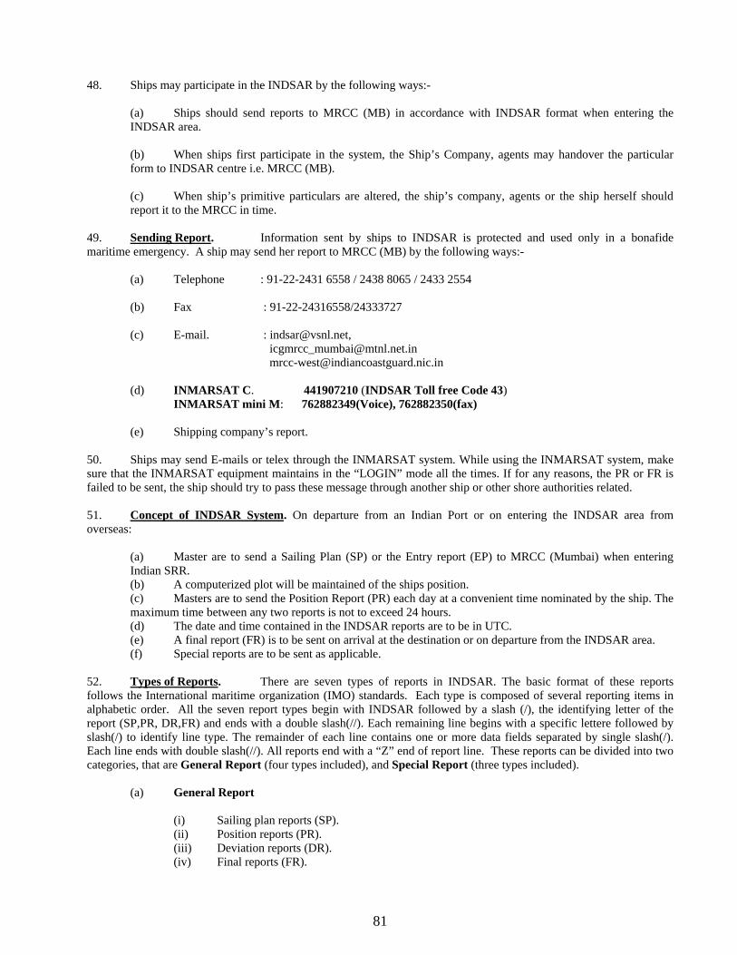
81
48. Ships may participate in the INDSAR by the following ways:- (a) Ships should send reports to MRCC (MB) in accordance with INDSAR format when entering the INDSAR area.
(b) When ships first participate in the system, the Ship’s Company, agents may handover the particular form to INDSAR centre i.e. MRCC (MB).
(c) When ship’s primitive particulars are altered, the ship’s company, agents or the ship herself should report it to the MRCC in time.
49. Sending Report. Information sent by ships to INDSAR is protected and used only in a bonafide maritime emergency. A ship may send her report to MRCC (MB) by the following ways:-
(a) Telephone : 91-22-2431 6558 / 2438 8065 / 2433 2554
(b) Fax : 91-22-24316558/24333727 (c) E-mail. : [email protected], [email protected] [email protected]
(d) INMARSAT C. 441907210 (INDSAR Toll free Code 43) INMARSAT mini M: 762882349(Voice), 762882350(fax)
(e) Shipping company’s report.
50. Ships may send E-mails or telex through the INMARSAT system. While using the INMARSAT system, make sure that the INMARSAT equipment maintains in the “LOGIN” mode all the times. If for any reasons, the PR or FR is failed to be sent, the ship should try to pass these message through another ship or other shore authorities related. 51. Concept of INDSAR System. On departure from an Indian Port or on entering the INDSAR area from overseas:
(a) Master are to send a Sailing Plan (SP) or the Entry report (EP) to MRCC (Mumbai) when entering Indian SRR.
(b) A computerized plot will be maintained of the ships position. (c) Masters are to send the Position Report (PR) each day at a convenient time nominated by the ship. The maximum time between any two reports is not to exceed 24 hours. (d) The date and time contained in the INDSAR reports are to be in UTC. (e) A final report (FR) is to be sent on arrival at the destination or on departure from the INDSAR area.
(f) Special reports are to be sent as applicable. 52. Types of Reports. There are seven types of reports in INDSAR. The basic format of these reports follows the International maritime organization (IMO) standards. Each type is composed of several reporting items in alphabetic order. All the seven report types begin with INDSAR followed by a slash (/), the identifying letter of the report (SP,PR, DR,FR) and ends with a double slash(//). Each remaining line begins with a specific lettere followed by slash(/) to identify line type. The remainder of each line contains one or more data fields separated by single slash(/). Each line ends with double slash(//). All reports end with a “Z” end of report line. These reports can be divided into two categories, that are General Report (four types included), and Special Report (three types included).
(a) General Report
(i) Sailing plan reports (SP). (ii) Position reports (PR). (iii) Deviation reports (DR). (iv) Final reports (FR).

82
(b) Special Report
(i) Dangerous goods reports (DG). (ii) Harmful substances reports (HS.) (iii) Marine pollutants reports (MP).
Formats, Contents and Requirements of the Reports 53. Sailing Plan (SP) INDSAR Reports. The SP should contain enough necessary information to initiate a plot and predict vessel’s actual position within 25 nautical miles at any time assuming that the sailing plan is followed exactly. Before leaving from an Indian port or when entering the INDSAR area from overseas, a ship should send the SP to the INDSAR Center and adhere to the following stipulations:
(a) This report should be sent within 24 hours before the ship entering the Indian SRR boundary or 2 hours after entering the boundary.
(b) This report should be sent within 2 hours before, upon, or after her departure from any Indian port.
Note: If there is any doctor, physicians assistant or nurse on board the ship, item V should be added into the SP. 54. Format of INDSAR SP of Ship’s entering Indian areas from overseas and berthing at Indian ports. The sailing plans require A, B, E, F, G, H, I, L and Z lines. The lines M, V and X lines are optional. Example
INDSAR Sailing Plan INDSAR/SP// A Vessel’s name and call sign A/ ANPINGI/BPOA// B Date and Time(UTC) 010700Z NOV// E Course E/160// F Speed F/150// G Last port of call G/SINGAPORE/0121N/10359E// H Date/Time(UTC) and position of entry into INDSAR areas
H/02300Z/0600N/09430E//
I Next port of call and Estimated time of arrival I/MUMBAI/1855N/07250E/150800Z// L Intended route (composed of some track segments)
L1/300/0121N/10359E // L2/260/0500N/07800E// L3/345/1800N/07200E//
M Coast Radio Stations Monitored, or communication methods
M/INMARSAT C//
X Next port of call X/ NEXT PORT /180800ZNOV// Z Ending of the report Z/EOR//
55. Format of INDSAR SP between two domestic ports. The lines A, B, E, F, G, H, I, L and Z for INDSAR SP should be reported. If necessary, the items and data fields E, K, N, O, S, T, U, W, X and / or Y may be added. Example
INDSAR Sailing Plan INDSAR/SP// A Vessel’s name and call sign A/ANPINGI/BPOA// F Speed F/150// G Last port of call G/MUMBAI/1855N/07250E// H Date/Time(UTC) and position of departing Indian coast ports
H/131900UTC/1855N/07250E//
I Next port of call and estimated time of arrival
I/VIZAG/210700UTC//

83
L Intended route(composed of some track segments) L1/165/1730N/07200E// L2/090/0500N/07815E// L3/035/2000N/08630E//
M Communication methods M/XSG// Z Ending of the report Z//
56. Format of INDSAR SP for departing indian ports for foreign ports. The lines A,B,E,F,G,H,I,L,Z for INDSAR SP should be reported . If necessary, the lines E, N, O, S, T, U, W, X and/or Y may be added. Example
INDSAR Sailing Plan INDSAR/SP// A Vessel’s name and callsign A/ANPINGI/BPOA// F Speed F/150// G Last port of call G/MUMBAI/1855N/07255E// H Date/Time(UTC) and position of departing Indian coast ports
H/020500UTC/1855N/07255E //
I Next port of call and estimated time of arrival
I/SINGAPORE/0121N/10359E /19600UTC//
K Date, time and point of exit from INDSAR area
K/160600UTC/0600N/09430E //
L Intended route(composed of some track segments)
L1/165/1730N/07200E// L2/080/0500N/07815E// L3/100/0600N/09430E// L1/145/0121N/10359E //
M Communication methods M/XSG//INMARSAT C// Z Ending of the report Z//
57. Format of INDSAR SP for transit of ships (only crossing the indsar area during the voyage from one foreign port to another foreign one). The lines A,B,E,F,G,I,L,Z for INDSAR SP should be reported .If necessary, the lines E, N,O,S,T,U,W,X and/or Y may be added. Example
INDSAR Sailing Plan INDSAR/SP// A Vessel’s name and callsign A/ANPINGI/BPOA// F Speed F/150// G Last port of call G/ KARACHI/2030N/06730E// H Date/Time(UTC) and position of departing ports
H/020500UTC/2030N/06730E//
I Next port of call and estimated time of arrival
I/COLOMBO/0730N/07950E/ 1306000UTC//
K Date, time and point of exit from INDSAR area K/080800UTC/0650N/07830E // L Intended route(composed of some track segments)
L1/155/2030N/06730E // L2/080/0500N/07815E// L3/100/0600N/09430E// L1/145/0121N/10359E //
M Communication methods M/XSG// Z Ending of the report Z//
58. Position Reports (INDSAR PR). The PR should be sent to INDSAR Center at the time prescribed or appointed. The first PR is required within 24 hours after the latest SP, thereafter at an interval of 24 hours or at the appointed daily reporting time. But the interval between two PRs must not exceed 24 hours until arrival at Indian coastal ports or departures from INDSAR boundary. Should a ship at any time be in a position more than 2 hours steaming from

84
the position predicted in its last intended route, the new PR or DR should be sent. The information contained in the PR will be used by the Center to update the plot. 59. If a Deviation Report (DR) is sent 2 hours before PR, then the next PR may be sent 24 hours after the DR. The ETA at the next port of call, or INDSAR area boundary should be confirmed in the last PR. The revised ETA may also be amended in PR. 60. If the duration of whole voyage is less than 24 hours, the ship is not required to send a PR, and ship should only requested to send a SP when commencing her voyage and a FR when arriving at the destination. 61. The lines A,B,C,E,F,N,Z for INDSAR PR should be reported. The I line is strongly recommended. If necessary, the items and data fields S, X and/or Y may be added. Example
INDSAR Position Report INDSAR/PR// A Vessel’s name and callsign A/ANPINGI/BPOA// B Time(GMT or UTC) B/090600Z// C Position (Lat/Long) C/1030N/07510E E Course E/165// F Speed F/150// I Next port of call and estimated time of arrival
I/TUTICORIN/0930N/07515 E/092300Z//
N Date/ time of next PR N/100600UTC// Z Ending of the report Z//
Notes
(a) Position Report should be sent at the time prescribed or appointed. (b) The ETA at Indian coast port or departing from INDSAR area must be confirmed in the last PR.
62. Deviation Report (INDSAR DR). This report should be sent as soon as any voyage information changes which could affect INDSAR’s ability to accurately predict the vessel’s position. Changes in course or speed due to weather change in destination, diverting to evacuate a sick or injured crew member, diverted to assist another vessel or any other vessel, or any deviation from the original Sailing Plan should be reported as soon as possible. The lines A,B,C,E,F,N,Z for INSAR PR should be reported. The line I and L are required if destination or route changes. The ‘I’ line is always recommended. The M and X lines are optional.
Example
INDSAR Deviation Report INDSAR/DR// A Vessel’s name and callsign A/ANPINGI/BPOA// B Time(GMT or UTC) B/090100UTC// C Position (Lat/Long) C/1030N/07530E// E Course E/160// I Next port of call and estimated time of arrival
I/TUTICORIN/090900UTC//
L Intended route(composed of some track segments)
L1/160/1030N/07530E// L1/040/0650N/07650E//
Z Ending of the report Z// 63. Final Report (INDSAR FR). Final Report should be sent upon when the ship arrives at the port of destination OR when the vessel exits the INDSAR area. lines A, K, Z for INDSAR should be reported.

85
Example
INDSAR Final Arrival Report INDSAR/FR// A Vessel’s name and callsign A/ANPINGI/BPOA// K Date/Time(UTC) and position of Exit from INDSAR coverage area or that of arrival at Indian coastal port and the port’s name
K/011321UTC/09430E 20E// or K/011321UTC/KOCHI//
Z Ending of the report Z// 64. Dangerous Goods Report (INDSAR DG). Dangerous Goods Report should be sent when an incident takes place involving the loss or likely loss overboard of packaged dangerous goods into the sea. The lines A,B,CM,Q,R,S,T,U,Z for INDSAR DG should be reported. If the condition of the ship is such that there is danger or further loss of packaged dangerous goods into the sea, item P of the standard reporting format should be reported.
Example
65. Harmful Substances Report (INDSAR HS). Harmful substances report should be sent when an incident takes place involving the discharge or probable discharge of oil (Annex I of MARPOL 73/78) or noxious liquid substances in bulk (Annex II of MARPOL 73/78). 66. The lines A, B,C, E, F, L, M, N, Q, R , S, T, U, X, Z for INDSAR HS should be reported, and P should be included if probable leakage.
INDSAR Dangerous Goods Report (INDSAR/DG// A Vessel’s name and callsign B Time(GMT or UTC) C Ship’s position (Lat/Long) M Communication methods P P1 Correct technical name or cargo’s name
P2 UN number or numbers P3 Dangerous Goods-Class P4 Names of manufacturers, consignee or consignor P5 Packing of cargo( including identification mark and methods of Transportation P6 Quantity and estimated condition of cargo
Q Q1 Relevant conditions of ship Q2 Ability to transfer cargo, ballast water and fuel
R R1 Correct technical name or cargo’s name R2 UN number or numbers R3 Dangerous Goods-Class R4 Names of manufacturers, consignee or consignor R5 Packing of cargo( including identification mark and methods of Transportation R6 Quantity and estimated condition of cargo R7 Whether the lost goods floating or sunk R8 Whether the loss is continuing R9 Cause of loss
S Weather condition T Ship owner and representatives U Ship’s size and type Z Ending of the report

86
Example
INDSAR Harmful Substance Report (INDSAR/HS// A Vessel’s name and callsign B Time(GMT or UTC) C Ship’s position (Lat/Long) E Course F Speed L Intended route(composed of some voyage segments) M Communication methods P P1 Correct technical name of oil noxious liquid substance on ship
P2 UN number or numbers P3 Pollution-Class(A,B,C or D) for noxious liquid substance P4 Names of manufacturers, consignee or consignor P5 Quantity
Q Q1 Relevant conditions of ship Q2 Ability to transfer cargo, ballast water and fuel
R R1 Correct technical name of oil noxious liquid substance discharged into sea R2 UN number or numbers R3 Pollution-Class(A,B,C or D) for noxious liquid substance R4 Names of manufacturers of noxious substance, or addresses of consignee or consignor R5 Estimated quantity of harmful substance R6 Whether the lost goods floating or sunk R7 Whether the loss is continuing R8 Cause of loss R9 Estimate the discharge , leakage and movement of the lost substance, if the liquid is harmful R10 Estimated spilt area
T Names, addresses, telephone and telex numbers of the ship owner and representatives X X1 Actions for the moving noxious liquid substance or such substance discharged by ship
X2 Assistance and salvage which have been requested and provided X3 Assisting or salvaging ships should report the detailed action planned take or being taken, if no details available at first, add it in the supplementary report.
Z Ending of the report 67. Marine Pollutants Report (INDSAR MP). Marine pollutants report should be sent in the case of loss or likely loss overboard or harmful substance in packaged form, identified in the International Maritime Dangerous Good Code as marine pollutants. (Annex III of MARPOL 73/78). 68. The lines A, B, C, M, Q, R, S, T, U, X, Z for INDSAR HS should be reported, and P should be included if probable leakage. Example
INDSAR Marine Pollutants Report (INDSAR/MP// A Vessel’s name and callsign B Time(GMT or UTC) C Ship’s position (Lat/Long) M Communication methods P (Refer to the item and data field in the Dangerous Goods Report) Q Q1 Relevant conditions of ship
Q2 Ability to transfer cargo, ballast water and fuel R R1 Correct technical name of cargo
R2 UN number or numbers R3 Dangerous Goods –Class

87
R4 Names of manufacturers, consignee or consignor R5 Packing of cargo(including identification mark and methods of transportation) R6 Quantity and estimated condition of cargo R7 Whether the loss goods floating or sunk R8 Whether the loss is continuing R9 Cause of loss
T Names, addresses, telephone and telex numbers of the ship owner and representatives X X1 Actions for the moving noxious liquid substance or such substance discharged by ship
X2 Assistance and salvage which have been requested and provided X3 Assisting or salvaging ships should report the detailed action planned take or being taken, if no details available at first, add it in the supplementary report.
Z Ending of the report 69. Reporting Format. INDSAR Reporting format and Procedure will be same as given in Appendix ‘A’ for INSPIRES. Ships to pass INDSAR reports through code 43 of INMARSAT ‘C’, Number 441907210. The procedure for position reporting on code 43 of the INMARSAT ‘C’ is given in Appendix ‘E’. 70. Receiving Stations.
(a) All the reports are to be prefixed INDSAR and forwarded to the MRCC (Mumbai) whose details are mentioned in Para 49. (b) Mariners are advised to strictly adhere to INDSAR reporting system and if for any reason a Master is
unable to pass his PR or FR he should attempt to pass a message through another ship, or harbour or other shore authority as appropriate. The MRCC Mumbai does not forward reports to other reporting systems. Ships are requested to pass these reports direct.
71. MARITIME SEARCH AND RESCUE (M-SAR) – "ISLEREP" The purpose of ISLEREP is to enhance navigational safety in and around the waters of A & N (Andaman & Nicobar) Islands and L & M (Lakshadweep and Minicoy) Islands thereby minimising the risk of a maritime accident and consequential pollution and major damage to the marine environment. These areas are internationally recognised as being of outstanding environmental importance. ISLEREP also provides the ability to respond more quickly in the event of any safety or pollution incident. Participation is encouraged for all categories of ships. 72. Participation. Ships of the following general categories are required to participate in the reporting system:- (a) All ships of 50 metres or greater in overall length; (b) All oil tankers*, liquefied gas carriers, chemical tankers or ships coming with the INF Code, regardless of length;
(c) Ships engaged in towing or pushing where the towing or pushing ship or the towed or pushed ship is a ship prescribed within the categories shown above or where the length of the tow, measured from the stern of the towing ship to the after end of the tow, exceeds 150 metres.
*For the purposes of this requirement "oil tanker" means ships defined at regulation 1(4) of Annex I to MARPOL 73/78 together with those ships other than oil tankers to which regulation 2 (2) of Annex I to MARPOL 73/78 applies, that is, ships "fitted with cargo spaces which are constructed and utilised to carry oil in bulk of an aggregate capacity of 200 cubic metres or more" Warships, Naval Auxiliaries and Government ships are encouraged to participate in the ISLEREP on a voluntary basis. 73. Operating Authority. ISLEREP - Island (M-SAR) Reporting (System) is operated under joint arrangements between the Indian Coast Guard and the A & N / L & M Administration. The system is manned and operated on a 24 hour basis by Island Administration personnel operating from the Ship Reporting Centre, Radio Call

88
Identity "ISLEREP CENTRE" with Port Blair radio at Port Blair and associated Islands or Kavaratti radio at Kavaratti or adjacent Islands. 74. Concept of ISLEREP. ISLEREP is based on a VHF voice reporting system employing a radio network along the A & N / L & M coasts and on Islands in the adjacent areas. Through this network certain categories of ships are required to report their entry into, and progress through the area. The purpose is to monitor compliance with the reporting requirement and provide enhanced ship traffic information at those locations. This will maintain a surface picture of participating ships and this will be established from position reports dead-reckoning. 75. Entering the ISLEREP Area. At the first designated reporting point after entering the area from seaward within 20 nautical miles of when sailing from a port within the area, ships are required to provide a position report (PR), with details such as identity, position, intended route, cargo and other supplementary information. The extent of the report will depend on whether the reporting ship has previously sent an INDSAR Sailing Plan (SP) message. If a ship is already an INDSAR reporter on first entry to ISLEREP, the ISLEREP system will require only a reduced PR from that ship. 76. Enroute Position Reports. As a monitor of progress through the reporting area, the enroute reporting have generally been placed at intervals of 80 - 100 nautical miles apart depending on locations and the siting of shore VHF radio stations. Position reports are generally limited to the identity of the ship, position, speed (or ETA) and any further information the Master considers might be of value to the system, such as concentrations of fishing vessels or abnormal weather conditions. In A & N Islands, a HF link called "ATLANTA" on frequency 8294 kHz (Day) and 6224 kHz (Night) is manned by Port authorities. HF watch keeping is also maintained off the Lakshadweep Islands between 0600 - 2200 hours (Indian Standard Time) on 4393.4, 6275, 7344 and 8275 kHz. Ships on tasks such as survey, research, aids to navigational support, tourist related activities or local trading operations, which may not be on continuous passage, are required to provide a PR to ISLEREP at intervals not exceeding 12 hours. Consistent with the aim of avoiding dual reporting, ships participating in INDSAR, when in the ISLEREP area, do not need to make separate INDSAR PRs. Instead the same can be messaged to INDSAR. 77. Leaving the ISLEREP. Ships sending their final report to the ISLEREP system when about to enter port or in vicinity of a "port of entry/departure" reporting point will be required to advise if this is a final INDSAR report (FR). Likewise ships sending their final report to the ISLEREP system when in the vicinity of an "area entry/departure" reporting must advise if they intend reporting to the INDSAR system for the remainder of their voyage in the Indian SRR area. 78. Special Reports - Defects, damage, deficiencies or other limitations. A ship must also advise ISLEREP when:
(a) It deviates significantly from the track reported in its last PR;
(b) It alters speed significantly, for reasons other than normal course and/or speed alterations;
(c) Damage or defects to the ship or its equipment which will affect its operation and/or seaworthiness; (d) Damage to the ship or its equipment means that a discharge of dangerous goods, harmful substances or marine pollutants is about to/or likely to happen.
Examples of such incidents include but are not limited to the following: failure or breakdown of steering gear, propulsion plant, electrical generating system, essential shipboard navigational aids, collision, grounding, fire, explosion, structural failure, flooding, cargo shifting. 79. Communications. Ships participating in ISLEREP must communicate with ISLEREP CENTRE using VHF radio channels 8 and 16 (H24 watch keeping by Port Blair Radio and Kavaratti Radio) as the primary means of communication. The working VHF channel to be used will depend on the ship's position. If they wish, ships can provide details of their cargo to INDSAR/ISLEREP by non-radio means, such as facsimile, telephone or Inmarsat C, provided this is done in advance of their first report. The language to be used for reports in the ISLEREP system will be English, using the IMO's Standard Marine Communication Phrases (SMCP) were necessary.

89
The Islands of A & N have a HF network call sign "ATLANTA" on frequency 8294 kHz (Day) and 6224 kHz (Night) whereas L & M Islands use VHF. Alternative communications may be utilised using one or more of the following (in order of preference): (a) Inmarsat C through ARVI LES using Toll Free Code 43; (b) Other Inmarsat (or non Inmarsat) phone/fax/telex service; (c) HF radiotelephone or telex services; 80. Automated Position Reporting via Inmarsat C. Vessels transiting the ISLEREP region are encouraged to participate in Automated Position Reporting (APR) via Inmarsat C code 43. Inmarsat C APR costs will be borne by the Indian Coast Guard. This is only for use when communications on the VHF network have failed and a satellite link with MRCC Mumbai (Inmarsat C 441907210) is necessary. 81. Types of ISLEREP Reports. The main reports are as follows:- (a) First ISLEREP PR if INDSAR SP already lodged (b) First ISLEREP if INDSAR SP not lodged (c) ISLEREP PR - Enroute (d) Final ISLEREP PR (e) ISLEREP PR reporting and changed circumstances The basic format for ISLEREP reports follows the International Maritime Organization (IMO) standard. The first line in every report begins with ISLEREP followed by a slash (/), the report type and ends with a double slash (//). Each remaining line begins with a specified letter followed by a slash (/) to identify the line type. The remainder of each line contains one or more data fields separated by single slashes (/). Each line ends with a double slash (//). All reports should end with a "Z" end- of-report line. For VHF reporting, ships do not need to prefix each field with IMO format letter, but may do so if they wish. 82. First ISLEREP PR if INDSAR SP already lodged. If the ship has already submitted an INDSAR Sailing plan (SP) for the voyage, the ship will (at the first reporting point) normally only need to: (a) Identify itself to the ISLEREP Centre ( b) Confirm that the ship is an INDSAR participant (c) Report its position (d) Confirm that there are no changes to the information provided, or alternatively (e) Report any changes or additional information relevant to the voyage Equivalent format field complying with IMO's general principles for ship reporting systems and ship reporting requirements. For VHF reporting, ships do not need to prefix each field with IMO format letter, but may do so if they wish. 83. Form of messages. A / Ship Name/ Call sign// B / Date/Time of ship's actual position (UTC) if within 20 n miles from the Island// C / Latitude / Longitude of ship's actual position if within 20 n miles from the island// E / Course in whole degrees True//

90
F / Speed in knots// X / Remarks// 84. First ISLEREP PR if INDSAR SP not lodged. If the ship does not intend reporting to INDSAR then a FULL ISLEREP PR in the following format must be sent. Equivalent format field complying with IMO's general principles for ship reporting systems and ship reporting requirements. For VHF reporting, ships do not need to prefix each field with IMO format letter, but may do so if they wish. 85. Form of messages. A / Ship Name/ Call sign/ IMO number// B / Date/Time of ship's actual position (UTC) if within 20 n miles from the Island// C / Latitude / Longitude of ship's actual position if within 20 n miles from the island// E / Course in whole degrees True// F / Speed in knots// J / Coastal pilot on board? (Yes/No)// L / Final Mandatory Entry/ anchoring in Island with name// O / Draft fore and aft in metres and tenths of metres// P / Cargo name Dangerous cargo (Yes/No)// Q / Defects and other limitations (Yes/No-supply details)// R / Brief details of type of pollution lost overboard (oil, chemicals, etc). See special reporting requirements (HS, DG or MP). Also report if any pollution sighted// U / Ship type/Length in metres/Gross Tonnage// X / Remarks// 86. ISLEREP PR – Enroute. Following the first report to ISLEREP CENTRE, further position reports are required:
(a) at each subsequent reporting of Islands and
(b) in any case at intervals not exceeding 12 hours Equivalent format field complying with IMO's general principles for ship reporting systems and ship reporting requirements. For VHF reporting, ships do not need to prefix each field with IMO format letter, but may do so if they wish. 87. Form of messages. A / Ship Name/ Call sign// B / Date/Time of ship's actual position (UTC) - if within 20 n miles from the Island// C / Latitude / Longitude of ship's actual position - if within 20 n miles from the Island// E / Course in whole degrees True// F / Speed in knots// X / Remarks// 88. Final ISLEREP PR. Ships should notify ISLEREP CENTRE when: (a) Departing the ISLEREP area or 20 n miles seaward from Island (b) Arriving at a port within the Island (A & N / L & M) If the ship is also an INDSAR reporting ship and is departing the ISLEREP area at the sea boundary it should notify ISLEREP CENTRE if it intends to continue reporting to INDSAR and if so, the Date/Time of the next INDSAR position report (PR). If the ship is arriving within a port at the ISLEREP area if should notify ISLEREP CENTRE that the report is also an INDSAR final report (FR).
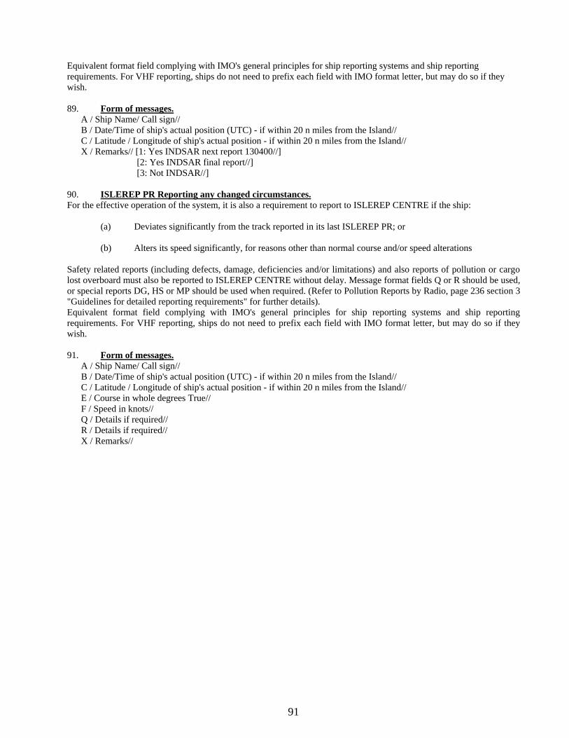
91
Equivalent format field complying with IMO's general principles for ship reporting systems and ship reporting requirements. For VHF reporting, ships do not need to prefix each field with IMO format letter, but may do so if they wish. 89. Form of messages. A / Ship Name/ Call sign// B / Date/Time of ship's actual position (UTC) - if within 20 n miles from the Island// C / Latitude / Longitude of ship's actual position - if within 20 n miles from the Island// X / Remarks// [1: Yes INDSAR next report 130400//] [2: Yes INDSAR final report//] [3: Not INDSAR//] 90. ISLEREP PR Reporting any changed circumstances. For the effective operation of the system, it is also a requirement to report to ISLEREP CENTRE if the ship: (a) Deviates significantly from the track reported in its last ISLEREP PR; or (b) Alters its speed significantly, for reasons other than normal course and/or speed alterations Safety related reports (including defects, damage, deficiencies and/or limitations) and also reports of pollution or cargo lost overboard must also be reported to ISLEREP CENTRE without delay. Message format fields Q or R should be used, or special reports DG, HS or MP should be used when required. (Refer to Pollution Reports by Radio, page 236 section 3 "Guidelines for detailed reporting requirements" for further details). Equivalent format field complying with IMO's general principles for ship reporting systems and ship reporting requirements. For VHF reporting, ships do not need to prefix each field with IMO format letter, but may do so if they wish. 91. Form of messages. A / Ship Name/ Call sign// B / Date/Time of ship's actual position (UTC) - if within 20 n miles from the Island// C / Latitude / Longitude of ship's actual position - if within 20 n miles from the Island// E / Course in whole degrees True// F / Speed in knots// Q / Details if required// R / Details if required// X / Remarks//

92
Appendix 'A' (Refers to Para 6)
STANDARD REPORTING FORMAT AND PROCEDURES
______________________________________________________________________________ Telegraphy Telephone Function Information required (alternative) ______________________________________________________________________________ Name of the system Name of the system ______________________________________________________________________________ INSPIRES INSPIRES System Identifier Ship reporting System State in full Types of Report Types of report 1. SP 1. Sailing Plan 2. PR 2. Position Report 3. DR 3. Deviation Report 4. FR 4. Final Report 5. Give in Full 5. Any other Report A (Alpha) Ship Ships name and Call Sign or ships station Identity B (Bravo) Time Date and Time A6 digit group giving day
of month of event (first two digits) hours and minutes UTC (last four digits)
C (Charlie) Position Position A4 digit group giving Lat. in Degree and Minute suffix with N/S and a four digit
group giving Long. in Degree and Minutes suffix with E/W. D (Delta) Position Position True bearings (first 3digits) and distance (two digits) in nautical miles from a clearly
identified landmark (State landmark) E (Echo) Course True Course A 3 digit group F (Foxtrot) Speed Speed A 3 digit group in knots and tenths of Knots. G (Golf) Departed Port of Departure Name of last port of call. H (Hotel) Entry Date, Time & Point Entry time expressed as If entry into system in(B) and exit position expressed as in (C) or (D). I (India) Destination and Destination and expected Name of port and date time Ee-Tee-Aye time of Arrival group expressed as in (B) J (Juliet) Pilot Pilot State whether a deep sea or local pilot is onboard.

93
_________________________________________________________________________________________________ Telegraphy Telephone Function Information required (alternative) _________________________________________________________________________________________________ K (Kilo) Exit Date, Time & Point of Exit time expressed as in (B) and exit from the system exit position expressed as in (C) or(D). L (Lima) Route Route information Intended track(see Note 1) M (Mike) Radio Radio State in full name of Communication Communication station/frequencies guarded N (November) Next Report Time of Next Report Date time group expressed in (B) O (Oscar) Draught Maximum present static 4 digits giving in metres and cms Draught in metres P (Papa) Cargo Cargo Cargo and brief details of any dangerous cargo including harmful substances and gases that could endanger persons or the environments. Q (Quebec) Defect/Damage Defect/Damage Brief details of defects, damage, deficiencies Deficiencies, Deficiencies, or other limitations Limitations other limitations R (Romeo) Pollution Description of pollution Brief details, including type of pollution (oil, incident or observation chemicals, etc.) position expressed as in (C) or (D) S (Sierra) Weather Weather conditions to report Brief details. cyclonic condition only *T (Tango) Agent Ships representative Details of name and particulars of ships representative for provision of information. *U (Uniform) Size and Type Ship size and Type Details length, breadth (in mts) gross tonnage and type etc. as required. V (Victor) Medical Medical personnel Doctor, Physician's assistant, Nurse, personnel No Medic. W (Whisky) Persons Total No. of persons State number Onboard X (XRay) Remarks Miscellaneous Any other information- give brief details. ______________________________________________________________________________________________
Note :- 1. For route information latitude and longitude should be given for each turning point, expressed as in C above, together in type of intended track between these points, e.g. RL (Rhumb-Line), 'GC' (Great circle) or coast or in the case of coastal sailing, the estimated date of passing significant point expressed by a digit group as in (B) above.
2. The International Code of Signals should be used in the report wherever language problems exist. When the International Code is used, the appropriate indicator should be inserted after the alphabetical index in the text.

94
*3. Information under 'T and U' groups shall be provided by the ship owner or agent of the Indian Ships. All other ships may include this information in sailing plan (SP) on departure from any Indian Port or entry into the system.(Only for INSPIRES)
Message should normally contain the following Groups:-
(a) SAILING PLAN : Consists of items A,B,E,F,G,I,L,M,N,O,P,V,W. Items C, D and H should be added on entering the area. * (Please see Note No.3) (b) POSITION REPORT: Consists of items A, B, C or, D,E,F,G, H, I, LM, N, O, P, V & W. (c) DEVIATION REPORT (DR): Consists of items A,B,C or D; items E, F, L,. N and Q if appropriate. (d) FINAL REPORT : Consists of items A, B, C or D items E, F, K & Lshould be added when leaving area.

95
Appendix 'B' (Refers to para 8)
RECEIVING STATIONS
---------------------------------------------------------------------------------------------------------------------------------------------- Sl.No. Station Call Freq.band Hours of Answering Ship Calling - Ship Working Sign Covered. Watch Freq.kHz Freq.Band Frequency* Keeping 1. COMCEN VTF2 4178- 1430 4283 (CH5) 4181.6 to 4182 Mumbai 4187 0230 (CH6) 4182 to 4182.4 VTF 3 6267- 1430- 6386.5 (CH5) 6272.4 to 6273 6 280.5 0230 (CH6) 6273 to 6273.6 VTF 4 8356 continuous 8566 (CH5)8363.2 to 8364 (CH6)8364 to 8364.8 Al VTF 5 12534- Continuous 12849 (CH5)12544.8 to12546 12561 (CH6)12546 to 12547.2 VTF 6 16712- 0230- 17132 (CH5)16726.4 to16728 16748 1430 (CH6)16728 to16729.6 2. COMCEN VTO 24178- 1430- 4283 (CH5)4181.6 to4182 Vishakhapatnam 4187 0230 (CH6)4182 to4182.4 VTO 3 6267- Continuous 6386.5 (CH5)6272.4 to 6273 6280.5 (CH6)6273 to 6273.6 VTO 4 8356- Continuous 8566 (CH5)8363.2 to 8364 8374 (CH6)8364 to 8364.8 ----------------------------------------------------------------------------------------------------------------------------------- *Ships are to indicate their working frequency to COMCEN.

96
Appendix 'C' (Refers to para 8)
Frequencies, Call Signs, Class of Emission, Scheduled Time and Details of Transmission of broadcast by COMCEN Mumbai (BN) and COMCEN Vishakhapatnam (VN) are tabulated below:- (a) Broadcast by COMCEN Mumbai (BN): ----------------------------------------------------------------------------------------------------------------------------------- Name of Call Sign Frequencies Class of Scheduled Time Details of station kHz Emission (UTC) Transmission ----------------------------------------------------------------------------------------------------------------------------------- COMCEN VTG 3 2072 0500 VTG 4 Mumbai VTG 4 4268 Main VTG 6 Continuous (Main Station) VTG 5 6467 Al 1500 VTG 7 VTG 6 8634 VTG 7 12808.5 0900 Repeat VTG 3 Night
VTG 8 16938 Period VTG 5 (1430--0230 UTC) VTG 9 22378 1215 Sunday VTG 8 Day Summary VTG 9 (0230-1430 UTC) (b) Broadcast by COMCEN Vishakhapatnam (VN): ----------------------------------------------------------------------------------------------------------------------------------- Name of Call Sign Frequencies Class of Scheduled Time Details of kHz Emission (UTC) Transmission ----------------------------------------------------------------------------------------------------------------------------------- COMCEN VTP 3 2295 0500 VTP 4 Vishakhapatnam Main Continuous VTP 4 4238 1500 VTP 6 (Supplementary Station) VTP 5 6418 Al VTP 6 8646 0900 Repeat VTP 3 Night Period (1430-0230 UTC). VTP 7 12840 VTP 5 1215 Sunday VTP 7 Day Summary (0230-1430 UTC) -----------------------------------------------------------------------

97
Appendix 'D' (Refers to para 21)
LIST OF PROPOSED PHYSICAL SHORE STATIONS
SL. No.
LOL No.
Name of Lighthouse
Lat /Long. N/E
MMSI No Remarks
1. 0396 Dwarka Point 22° 14.2’ N 68° 57.5’ E
004192211
RCC Jamnagar
2. 0398 Navadra 21° 56.5’ N 69° 13.9’ E
004192212
3. 0400 Porbandar 21° 37.3’ N 69° 37.2’ E
004192213
4. 0404 Navibander 21° 27.0’N 69° 47.2’ E
004192214
5. 0406 Mangrol 21° 06.5' N 70° 06.3' E
004192215
6. 0410 Veraval 20° 54.6' N 70° 21.2' E
004192216
7. 0414 Diu Head 20° 41.5' N 70° 49.7' E
004192217
8. 0432 Jafarabad 20° 51.4' N 71° 22.9' E
004192218
9. 0444 Gopnath 21° 12.2' N 72° 06.6' E
004192219
10. 0448 Piram Island 21° 35.9' N 72° 21.2' E
004192220
11. 0470 Luhara Point 21° 39.5' N 72° 32.9' E
004192221
RCC Mumbai
12. 0476 Hazira 21° 05.5' N 72° 38.6' E
004192222
13. 0479 Kanai Creek 20° 48.7' N 72° 49.7' E
004192223
14. 0489 Umargam 20° 11.7' N 72° 45.0' E
004192224
15. 0491.5 Tarapur Point 19°50.7’ E 72°39.5’N
004192225
16. 0499 Utan 19° 16.5' N 72° 46.8' E
004192226
17. 0558 Korlai Fort 18° 32.3' N 72° 54.5' E
004192227
18. 0562 Nanwell Point 18° 16.8' N 72° 56.3' E
004192228
19. 0566 Tolkeshwar Point
17° 33.9' N 73° 08.5' E
004192229
20. 0580 Ratnagiri 16° 59.2' N 73° 16.4' E
004192230
21. 0586 Wagapur Point 16° 36.3' N 73° 19.3' E
004192231
22. 0590 Devgarh 16° 23.3' N 73° 22.6' E
004192232
23. 0598 Vengurla Point 15° 51.2' N 73° 37.0' E
004192233
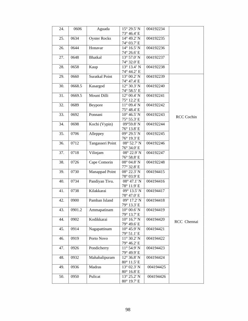
98
24. 0606 Aguada 15° 29.5' N 73° 46.4' E
004192234
25. 0634 Oyster Rocks 14° 49.2' N 74° 03.7' E
004192235
26. 0644 Honavar 14° 16.5' N 74° 26.6' E
004192236
27. 0648 Bhatkal 13° 57.0' N 74° 32.0' E
004192237
28. 0658 Kaup 13° 13.4’ N 74° 44.2’ E
004192238
29. 0660 Suratkal Point 13° 00.2' N 74° 47.4' E
004192239
RCC Cochin
30. 0668.5 Kasargod 12° 30.3' N 74° 58.5’ E
004192240
31. 0669.5 Mount Dilli 12° 00.4' N 75° 12.2' E
004192241
32. 0689 Beypore 11° 09.4' N 75° 48.4' E
004192242
33. 0692 Ponnani 10° 46.5' N 75° 55.3' E
004192243
34. 0698 Kochi (Vypin) 09°59.8' N 76° 13.8' E
004192244
35. 0706 Alleppey 09° 29.5' N 76° 19.3' E
004192245
36. 0712 Tangasseri Point 08° 52.7' N 76° 34.0' E
004192246
37. 0718 Vilinjam 08° 22.9' N 76° 58.8' E
004192247
38. 0726 Cape Comorin 08° 04.8' N 77° 32.8' E
004192248
RCC Chennai
39. 0730 Manappad Point 08° 22.3' N 78° 03.9' E
004194415
40. 0734 Pandiyan Tivu. 08° 47.1' N 78° 11.9' E
004194416
41. 0738 Kilakkarai 09° 13.5' N 78° 47.0' E
004194417
42. 0900 Pamban Island 09° 17.2' N 79° 13.3' E
004194418
43. 0901.2 Ammapatinam 10° 00.6' N 79° 13.7' E
004194419
44. 0902 Kodikkarai 10° 16.7' N 79° 49.6' E
004194420
45. 0914 Nagapattinam 10° 45.9' N 79° 51.1' E
004194421
46. 0919 Porto Novo 11° 30.2' N 79° 46.2' E
004194422
47. 0926 Pondicherry 11° 54.9' N 79° 49.9' E
004194423
48. 0932 Mahabalipuram 12° 36.8' N 80° 11.5' E
004194424
49. 0936 Madras 13° 02.3' N 80° 16.8' E
004194425
50. 0950 Pulicat 13° 25.2' N 80° 19.7' E
004194426

99
51. 0951 Armagon 13° 53.5' N
80° 12.3' E 004194427
RCC Vishakahpatnam
52. 0952 Krishnapatnam 14° 15.2' N 80° 07.7' E
004194428
53. 0952.9 Vodarevu 15° 48 0' N 80° 25.0' E
004194429
54. 0952.5 Ramaypatnam 15° 02.7' N 80° 03.0' E
004194430
55. 0953 Nagayalanka 15° 47.2' N 80° 59.2' E
004194431
56. 0955 Machilipatnam 16° 14.8' N 81° 14.0' E
004194432
57. 0957 Antervedi 16° 19.0' N 81° 43.6' E
004194433
58. 0958 Sacramento 16° 35.2' N 82° 16.8' E
004194434
59. 0964 Vakalapudi 17° 00.8' N 82° 17.1' E
004194435
60. 0966 Pentakota 17° 18.0' N 82° 37.0' E
004194436
61. 0970 Dolphin’s Nose 17° 40.5' N 83° 17.7’ E
004194437
62. 0980 Santapile 18° 03.9' N 83° 38.4' E
004194438
63. 0982 Kalingapatnam 18° 20.4' N 84° 07.6' E
004194439
RCC Kolkata
64. 0986 Baruva 18° 52.8' N 84° 35.8 ' E
004194440
65. 0988 Gopalpur 19° 15.3' N 84° 54.5' E
004194441
66. 1002 Puri 19° 47.7' N 85° 49.8' E
004194442
67. 1003 Chandrabhaga 19° 52.1' N 86° 06.6' E
004194443
71. 1004.4 Paradip 20° 15.3' N 86° 39.5' E
004194444
72. * Maipura 20° 42.5' N 87° 15.0' E
004194445
73. 1028 Sagar Island 21° 39.4' N 88° 02.9' E
004194446
74. Balasore 21° 29.18' N 86° 55.01' E
004194447
* Yet to be installed.

100
Appendix 'E' (Refers to para 69)
PROCEDURE FOR POSITION REPORTING FOR 'INDSAR'
Open Address Book (F3)
Select New Write pos or 43 Choose Special access (use space bar to choose) Write 43 against special access code Choose 7 bit The OK ESC
Now 43 has an entry in your address book
Go to File (use ESC to do this or Alt F) Select New telex And then compose your message Latitude ………………………. Longitude ………………………. Course …………………………. Speed …………………….. Time …………………………
Add whatever relevant information required as per INDSAR
Then press Alt T to open Transmit window Write pos or 43 (whatever you have mentioned in the address book) Enter.
(Also up down arrow can be used) Choose Earth Station (use space bar to choose from list) Enter Text in editor Enter Routine Enter Request confirmation Enter Immediate transmission Enter Then Send Enter
After some time go to logs choose trans and see whether your message has been transmitted successfully. If not, goto the MRN and contact LES.

101
Special Notice No. 9: FIRING PRACTICE AND EXERCISE AREAS; DANGER AREAS. 1. Firing and bombing practices and Defence exercises, take place in a number of areas off the coasts of India. 2. Although limits of practice areas are not, in all cases, shown on charts and descriptions of areas do not appear in the Sailing Directions, these are given in the Appendix to this notice which may be plotted on the appropriate charts. Such range beacons, lights and marking buoys as may be of assistance to the mariner or targets which might be a danger to navigation will however, be indicated on navigational charts and, when appropriate, in Sailing Directions. Lights will be mentioned in the List of Lights. Precautions to be observed by mariners are given in paragraph 6 to 9 of this notice. 3. The principal types of practices carried out are:- (a) Bombing practice from aircraft:-Warning signals are usually shown. (b) Air to air, and air to sea or ground firing.
(i) The former is carried out by aircraft at a large white or red sleeve, a winged target or flag towed by another aircraft moving on a steady course. The latter is carried out from aircraft at towed or stationary target on sea or land, the firing taking place to seaward in the case of those on land. (ii) As a general rule, warning signals are shown when the targets are stationary, but not when towed targets are used. (iii) All marine craft operating as range safety craft, target towers or control launches for remote controlled targets will display for identification purposes, while in or in the vicinity of the danger area, a large red flag at the masthead.
(c) Anti-aircraft(AA) firing. (i) This may be from A.A. guns or machine guns at a target towed by aircraft as in
(b)above, a pilot less target aircraft, or at balloons or kites. Practice may take place from shore batteries or ships.
(ii) Warning signals, as a rule are shown from shore batteries. ships fly a red flag.
(d) Firing from shore batteries or ships at sea at fixed or floating targets. Warning signals usually shown as in (c).
(e) Rocket and Guided Weapons firing.
(i) These may take the form of (b), (c) or (d) above. All such firing are conducted under (Air and Sea) Range procedure. Devices are generally incorporated whereby the missiles may be destroyed should their flights be erratic. (ii) Warning signals are usually shown as in (c) above.
4. Warning signals, when given, usually consist of red flags by day and red fixed or red flashing lights at night. The absence of any such signal cannot, however, be accepted as evidence that a practice area does not exist. Warning signals are shown from shortly before practice commences until it ceases. 5. Ships and aircraft carrying out night exercises may illuminate with bright coloured flares. To avoid confusion with International distress signals red or orange flares will be used in emergency only. 6. CAUTION: A vessel may be aware of the existence of a firing area from NAVAREA VIII warning messages, Coastal Warning messages, Local Notices to Mariners and by observing the warning signals or the practice.
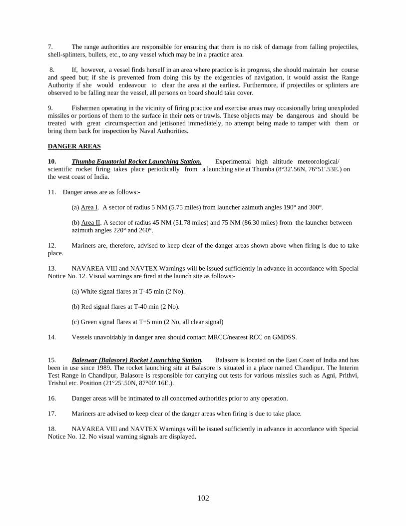
102
7. The range authorities are responsible for ensuring that there is no risk of damage from falling projectiles, shell-splinters, bullets, etc., to any vessel which may be in a practice area. 8. If, however, a vessel finds herself in an area where practice is in progress, she should maintain her course and speed but; if she is prevented from doing this by the exigencies of navigation, it would assist the Range Authority if she would endeavour to clear the area at the earliest. Furthermore, if projectiles or splinters are observed to be falling near the vessel, all persons on board should take cover. 9. Fishermen operating in the vicinity of firing practice and exercise areas may occasionally bring unexploded missiles or portions of them to the surface in their nets or trawls. These objects may be dangerous and should be treated with great circumspection and jettisoned immediately, no attempt being made to tamper with them or bring them back for inspection by Naval Authorities.
DANGER AREAS 10. Thumba Equatorial Rocket Launching Station. Experimental high altitude meteorological/ scientific rocket firing takes place periodically from a launching site at Thumba (8°32'.56N, 76°51'.53E.) on the west coast of India. 11. Danger areas are as follows:- (a) Area I. A sector of radius 5 NM (5.75 miles) from launcher azimuth angles 190° and 300°. (b) Area II. A sector of radius 45 NM (51.78 miles) and 75 NM (86.30 miles) from the launcher between
azimuth angles 220° and 260°. 12. Mariners are, therefore, advised to keep clear of the danger areas shown above when firing is due to take place. 13. NAVAREA VIII and NAVTEX Warnings will be issued sufficiently in advance in accordance with Special Notice No. 12. Visual warnings are fired at the launch site as follows:-
(a) White signal flares at T-45 min (2 No). (b) Red signal flares at T-40 min (2 No). (c) Green signal flares at T+5 min (2 No, all clear signal)
14. Vessels unavoidably in danger area should contact MRCC/nearest RCC on GMDSS.
15. Baleswar (Balasore) Rocket Launching Station. Balasore is located on the East Coast of India and has been in use since 1989. The rocket launching site at Balasore is situated in a place named Chandipur. The Interim Test Range in Chandipur, Balasore is responsible for carrying out tests for various missiles such as Agni, Prithvi, Trishul etc. Position (21°25'.50N, 87°00'.16E.). 16. Danger areas will be intimated to all concerned authorities prior to any operation. 17. Mariners are advised to keep clear of the danger areas when firing is due to take place. 18. NAVAREA VIII and NAVTEX Warnings will be issued sufficiently in advance in accordance with Special Notice No. 12. No visual warning signals are displayed.

103
19. Satish Dhawan Space Centre, SHAR, Sriharikota. Experimental high altitude satellite/sounding rocket launching takes place periodically from Sriharikota station on the East Coast of India. 20. Sounding Rocket Launching Station (13°41'N, 80°14'E). Danger areas are as follows:-
(a) RH 200/RH 300 (i) Danger zone-1 is a circle of 5 nautical miles from the launcher.
(ii) Danger zone-2 is a sector of radius of 15 nautical miles between azimuth angles of 70° and 110° from the launcher. (iii) Danger zone-3 is a sector within radius of 40 nautical miles and 70 nautical miles between azimuth angles of 70° and 110° from the launcher.
(b) RH 200 Stretched version (13°41'N, 80°14'E) (i) Danger zone-1 is a circle of 5 nautical miles from the launcher.
(ii) Danger zone-2 is a sector of radius of 15 nautical miles and 30 nautical miles between azimuth angles of 80° and 120° from the launcher. (iii) Danger zone-3 is a sector within radius of 40 nautical miles and 60 nautical miles between azimuth angles of 80° and 120° from the launcher.
(c) RH 560 variant-1 (13°41'.73N, 80°14'.08E) (i) Danger zone-1 is a circle of 5 nautical miles from the launcher.
(ii) Danger zone-2 is a sector of radius of 25 nautical miles between azimuth angles of 90° and 130° from the launcher. (iii) Danger zone-3 is a sector within radius of 180 nautical miles and 300 nautical miles between azimuth angles of 90° and 130° from the launcher.
(d) RH 560 variant-2 (13°41'.73N, 80°14'.08E) (i) Danger zone-1 is a circle of 12 nautical miles from the launcher.
(ii) Danger zone-2 is sector between radii of 50 nautical miles and 250 nautical miles from launch pad coordinates and between azimuth angles of 80° and 120° from true north.
21. Satellite Launching missions. Danger areas are as follows:-
(a) PSLV- VARIANT-1 (13°44'N, 80°14'.2E/13°43'.9N, 80°14'.2E) (sun Synchronous orbit) (i) Danger zone-1 is a circle of 10 nautical miles from the launcher.
(ii) Danger zone-2 is sector between radii of 115 nautical miles and 165 nautical miles from launcher and between azimuth angles 130° and 150° from true north. (iii) Danger zone-3 is a rectangular area enclosed by the following positions:- 9°00'N, 84°30'E 9°00'N, 85°00'E 7°30'N, 84°30'E 7°30'N, 85°00'E (iv) Danger zone-4 is a rectangular area enclosed by the following positions:- 00°50'S, 80°50'E 00°50'S, 82°50'E 04°50'S, 80°50'E 04°50'S, 82°50'E (v) Danger zone-5 is a rectangular area enclosed by the following positions:- 29°30'S, 72°00'E 29°30'S, 76°00'E 34°30'S, 72°00'E 34°30'S, 76°00'E

104
(b) PSLV- VARIANT-2 (13°44'N, 80°14'.2E/13°43'.9N, 80°14'.2E) (Sun Synchronous orbit)
(i) Danger zone-1 is a circle of 10 nautical miles around the launcher.
(ii) Danger zone-2 is sector between radii of 20 nautical miles and 40 nautical miles from launcher and between azimuth angles 130° and 150° from true north. (iii) Danger zone-3 is a sector between radii of 100 nautical miles and 160 nautical miles from launcher and between azimuth angles 130° and 150° from true north. (iv) Danger zone-4 is a sector between radii of 180 nautical miles and 200 nautical miles from launcher and between azimuth angles 130° and 150° from true north. (v) Danger zone-5 is a rectangular area enclosed by the following positions:- 9°00'N, 85°00'E 9°00'N, 85°30'E 7°30'N, 85°30'E 7°30'N, 85°00'E (vi) Danger zone-6 is a rectangular area enclosed by the following positions:- 04°30'S, 80°50'E 04°30'S, 82°50'E 08°30'S, 82°50'E 08°30'S, 80°50'E
(vii) Danger zone-7 is a rectangular area enclosed by the following positions:- 40°30'S, 72°00'E 40°30'S, 76°00'E 45°30'S, 76°00'E 45°30'S, 72°00'E
(c) PSLV- VARIANT-3 (13°44'N, 80°14'.2E/13°43'.9N, 80°14'.2E) (Geo Transfer orbit)
(i) Danger zone-1 is a circle of 10 nautical miles around the launcher.
(ii) Danger zone-2 is a rectangular area bounded by the following coordinates:- 12°45'N, 82°00'E 12°45'N, 84°00'E 13°45'N, 82°00'E 13°45'N, 84°00'E (iii) Danger zone-3 is a rectangular area bounded by the following coordinates:- 12°00'N, 86°45'E 12°00'N, 87°15'E 12°45'N, 86°45'E
12°45'N, 87°15'E (iv) Danger zone-4 is a rectangular area enclosed by the following coordinates:- 10°00'N, 95°00'E 10°00'N, 95°30'E 11°00'N, 95°00'E
11°00'N, 95°30'E (v) Danger zone-5 is a rectangular area enclosed by the following coordinates:- 19°00'S, 132°00'W 21°00'S, 132°00'W
16°00'S, 120°00'W 18°00'S, 120°00'W
(d) PSLV- VARIANT-4 (13°44'N, 80°14'.2E/13°43'.9N, 80°14'.2E) (Geo Transfer orbit)
(i) Danger zone-1 is a circle of 10 nautical miles around the launcher. (ii) Danger zone-2 is sector between radii of 40 nautical miles and 75 nautical miles from launch pad and between azimuth angles of 80° and 125° from true north.

105
(iii) Danger zone-3 is a rectangular area bounded by the following coordinates:- 12°45'N, 82°45'E 13°15'N, 82°45'E 13°15'N, 84°00'E
12°45'N, 84°00'E (iv) Danger zone-4 is a rectangular area bounded by the following coordinates:- 12°25'N, 84°10'E 13°00'N, 84°10'E 13°00'N, 85°40'E
12°25'N, 85°40'E (v) Danger zone-5 is a rectangular area bounded by the following coordinates:- 11°25'N, 88°10'E 12°00'N, 88°10'E
12°00'N, 89°10'E 11°25'N, 89°10'E
(vi) Danger zone-6 is a rectangular area enclosed by the following coordinates:- 8°50'N, 94°30'E 10°50'N, 94°30'E
10°50'N, 95°30'E 8°50'N, 95°30'E
(vii) Danger zone-7 is a rectangular area enclosed by the following coordinates:- 16°30'S, 130°00'W 17°30'S, 130°00'W
8°00'S, 90°00'W 8°50'S, 90°00'W
(e) GSLV- VARIANT-1 (13°44'N, 80°14'.2E/13°43'.9N, 80°14'.2E) (Geo Transfer orbit)
(i) Danger zone-1 is a circle of 5 nautical miles around the launcher.
(ii) Danger zone-2 is sector of radius 15 nautical miles from launcher, between azimuth angles of 45° and 160° from true north. (iii) Danger zone-3 is a rectangular area bounded by the following coordinates:- 11°15'N, 85°00'E 11°15'N, 86°45'E 12°30'N, 85°00'E
12°30'N, 86°45'E (iv) Danger zone-4 is a rectangular area bounded by the following coordinates:- 10°15'N, 88°30'E 10°15'N, 90°30'E 11°30'N, 88°30'E
11°30'N, 90°30'E
(f) GSLV- VARIANT-2 (13°44'N, 80°14'.2E/13°43'.9N, 80°14'.2E) (Geo Transfer orbit)
(i) Danger zone-1 is a circle of 5 nautical miles around the launcher. (ii) Danger zone-2 is sector of radius 15 nautical miles from launcher, between azimuth angles of 45° and 160° from true north. (iii) Danger zone-3 is a rectangular area bounded by the following coordinates:- 11°30'N, 85°00'E 11°30'N, 86°45'E 12°30'N, 86°45'E
12°30'N, 85°00'E (iv) Danger zone-4 is a rectangular area bounded by the following coordinates:- 10°15'N, 88°15'E 10°15'N, 90°30'E 11°30'N, 90°30'E
11°30'N, 88°15'E

106
(v) Danger zone-5 is a rectangular area bounded by the following coordinates:- 8°00'N, 94°45'E 8°00'N, 95°30'E 9°00'N, 90°30'E
9°00'N, 94°45'E 22. Mariners are advised to keep clear of the above danger areas when launching is due to take place. However, as per mission requirement these danger areas are likely to be changed marginally. 23. NAVAREA VIII and NAVTEX Warnings will be issued sufficiently in advance in accordance with Special Notice No. 12. No visual warning signals are displayed. 24. Vessels unavoidably in danger areas should contact MRCC Chennai.

107
Appendix 'A' (Refers to Para 2)
FIRING PRACTICE AND NAVAL EXERCISE AREAS
1. Bedi (Off Balachadi). Firing Area enclosed by the following positions:- (a) 22°49'.00N, 70°06'.00E (c) 22°38'.25N, 70°09'.33E (b) 22°45'.83N, 70°13'.17E (d) 22°41'.17N, 70°01'.83E 2. Nora Island. Firing Area of 2 miles around Nora Island (22°31'.00N, 69°20'.50E approx.). 3. Dwarka. (i) Firing area enclosed by the following positions:- (a) 22°18'.50N, 68°25'.00E (d) 21°00'.00N, 69°40'.50E (b) 22°06'.00N, 68°49'.00E (e) 21°30'.50N, 68°48'.50E (c) 21°30'.75N, 69°27'.00E (ii) Rushton Firing Area. Enclosed by the following positions:-
(a) 22°06'.00N, 68°49'.00E (c) 21°15'.00N, 69°08'.00E (b) 21°30'.75N, 69°27'.00E (d) 21°49'.00N, 68°31'.50E 4. Off Diu. (i) Firing Exercise Area For IN-AF, Area Q
(a) 20°30'.00N, 70°00'.00E (c) 19°14'.00N, 69°40'.00E (b) 20°00'.00N, 71°10'.00E (d) 19°10'.00N, 70°50'.00E
5. Mumbai. (i) General Firing Area "A". Enclosed by the following positions:-
(a) 18°28'.00N, 70°56'.00E (c) 18°10'.00N, 70°56'.00E (b) 18°28'.00N, 71°16'.00E (d) 18°10'.00N, 71°16'.00E Reference position "AA" 18°19'.00N, 71°31'.00E
(ii) Surface and AA Firing Area "B". Enclosed by the following positions:-
(a) 17°48'.00N, 71°52'.00E (c) 17°28'.00N, 71°52'.00E (b) 17°48'.00N, 72°10'.00E (d) 17°28'.00N, 72°10'.00E Reference position "BB" 17°38'.00N, 72°01'.00E
(iii) Firing from Middle Ground. Enclosed by the following positions:-
(a) 18°50'.00N, 72°54'.50E (e) 18°55'.17N, 72°50'.97E (b) 18°54'.50N, 72°54'.00E (f) 18°54'.65N, 72°50'.58E (c) 18°54'.30N, 72°54'.00E (g) 18°54'.39N, 72°50'.35E (d) 18°50'.00N, 72°54'.30E (h) 18°55'.10N, 72°54'.50E
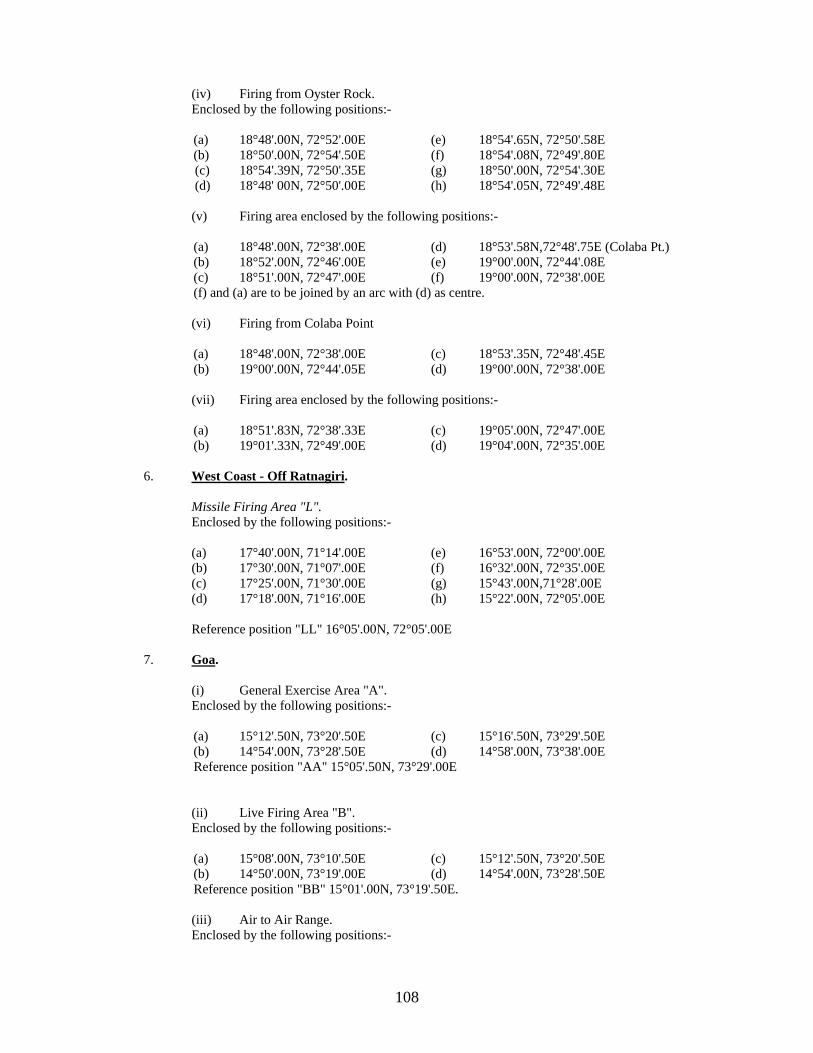
108
(iv) Firing from Oyster Rock. Enclosed by the following positions:-
(a) 18°48'.00N, 72°52'.00E (e) 18°54'.65N, 72°50'.58E (b) 18°50'.00N, 72°54'.50E (f) 18°54'.08N, 72°49'.80E (c) 18°54'.39N, 72°50'.35E (g) 18°50'.00N, 72°54'.30E (d) 18°48' 00N, 72°50'.00E (h) 18°54'.05N, 72°49'.48E
(v) Firing area enclosed by the following positions:-
(a) 18°48'.00N, 72°38'.00E (d) 18°53'.58N,72°48'.75E (Colaba Pt.) (b) 18°52'.00N, 72°46'.00E (e) 19°00'.00N, 72°44'.08E (c) 18°51'.00N, 72°47'.00E (f) 19°00'.00N, 72°38'.00E (f) and (a) are to be joined by an arc with (d) as centre.
(vi) Firing from Colaba Point
(a) 18°48'.00N, 72°38'.00E (c) 18°53'.35N, 72°48'.45E (b) 19°00'.00N, 72°44'.05E (d) 19°00'.00N, 72°38'.00E
(vii) Firing area enclosed by the following positions:-
(a) 18°51'.83N, 72°38'.33E (c) 19°05'.00N, 72°47'.00E (b) 19°01'.33N, 72°49'.00E (d) 19°04'.00N, 72°35'.00E
6. West Coast - Off Ratnagiri. Missile Firing Area "L". Enclosed by the following positions:- (a) 17°40'.00N, 71°14'.00E (e) 16°53'.00N, 72°00'.00E (b) 17°30'.00N, 71°07'.00E (f) 16°32'.00N, 72°35'.00E (c) 17°25'.00N, 71°30'.00E (g) 15°43'.00N,71°28'.00E (d) 17°18'.00N, 71°16'.00E (h) 15°22'.00N, 72°05'.00E Reference position "LL" 16°05'.00N, 72°05'.00E 7. Goa. (i) General Exercise Area "A". Enclosed by the following positions:-
(a) 15°12'.50N, 73°20'.50E (c) 15°16'.50N, 73°29'.50E (b) 14°54'.00N, 73°28'.50E (d) 14°58'.00N, 73°38'.00E Reference position "AA" 15°05'.50N, 73°29'.00E
(ii) Live Firing Area "B". Enclosed by the following positions:-
(a) 15°08'.00N, 73°10'.50E (c) 15°12'.50N, 73°20'.50E (b) 14°50'.00N, 73°19'.00E (d) 14°54'.00N, 73°28'.50E Reference position "BB" 15°01'.00N, 73°19'.50E.
(iii) Air to Air Range. Enclosed by the following positions:-
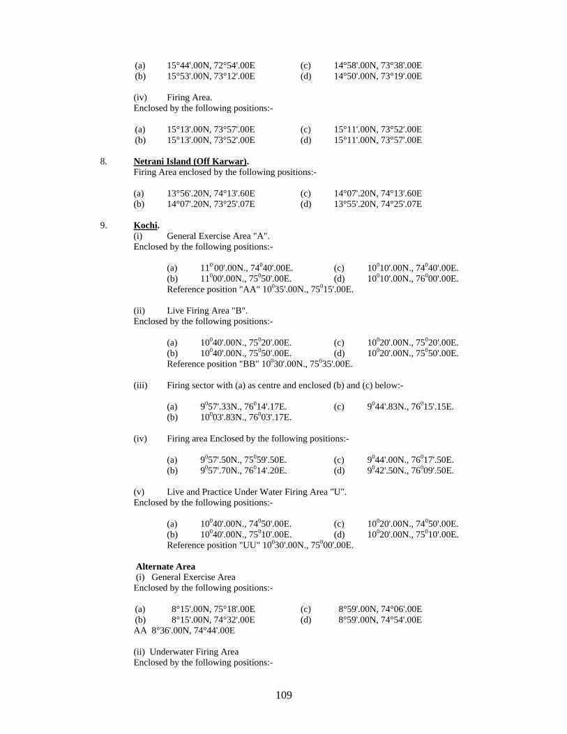
109
(a) 15°44'.00N, 72°54'.00E (c) 14°58'.00N, 73°38'.00E (b) 15°53'.00N, 73°12'.00E (d) 14°50'.00N, 73°19'.00E
(iv) Firing Area. Enclosed by the following positions:-
(a) 15°13'.00N, 73°57'.00E (c) 15°11'.00N, 73°52'.00E (b) 15°13'.00N, 73°52'.00E (d) 15°11'.00N, 73°57'.00E
8. Netrani Island (Off Karwar). Firing Area enclosed by the following positions:- (a) 13°56'.20N, 74°13'.60E (c) 14°07'.20N, 74°13'.60E (b) 14°07'.20N, 73°25'.07E (d) 13°55'.20N, 74°25'.07E 9. Kochi. (i) General Exercise Area "A". Enclosed by the following positions:-
(a) 110 00'.00N., 74040'.00E. (c) 10010'.00N., 74040'.00E. (b) 11000'.00N., 75050'.00E. (d) 10010'.00N., 76000'.00E. Reference position "AA" 10035'.00N., 75015'.00E.
(ii) Live Firing Area "B". Enclosed by the following positions:-
(a) 10040'.00N., 75020'.00E. (c) 10020'.00N., 75020'.00E. (b) 10040'.00N., 75050'.00E. (d) 10020'.00N., 75050'.00E. Reference position "BB" 10030'.00N., 75035'.00E.
(iii) Firing sector with (a) as centre and enclosed (b) and (c) below:-
(a) 9057'.33N., 76014'.17E. (c) 9044'.83N., 76015'.15E. (b) 10003'.83N., 76003'.17E.
(iv) Firing area Enclosed by the following positions:-
(a) 9057'.50N., 75059'.50E. (c) 9044'.00N., 76017'.50E. (b) 9057'.70N., 76014'.20E. (d) 9042'.50N., 76009'.50E.
(v) Live and Practice Under Water Firing Area "U". Enclosed by the following positions:-
(a) 10040'.00N., 74050'.00E. (c) 10020'.00N., 74050'.00E. (b) 10040'.00N., 75010'.00E. (d) 10020'.00N., 75010'.00E. Reference position "UU" 10030'.00N., 75000'.00E.
Alternate Area (i) General Exercise Area
Enclosed by the following positions:-
(a) 8°15'.00N, 75°18'.00E (c) 8°59'.00N, 74°06'.00E (b) 8°15'.00N, 74°32'.00E (d) 8°59'.00N, 74°54'.00E
AA 8°36'.00N, 74°44'.00E
(ii) Underwater Firing Area Enclosed by the following positions:-
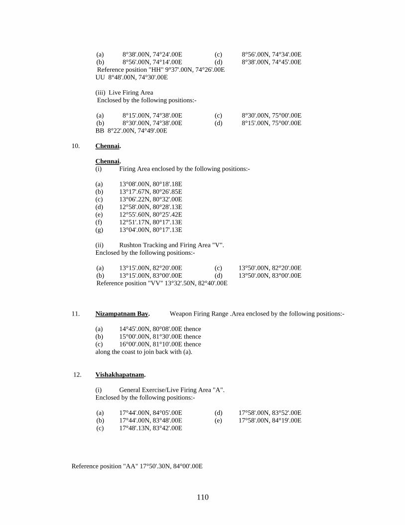
110
(a) 8°38'.00N, 74°24'.00E (c) 8°56'.00N, 74°34'.00E (b) 8°56'.00N, 74°14'.00E (d) 8°38'.00N, 74°45'.00E
Reference position "HH" 9°37'.00N, 74°26'.00E UU 8°48'.00N, 74°30'.00E (iii) Live Firing Area
Enclosed by the following positions:-
(a) 8°15'.00N, 74°38'.00E (c) 8°30'.00N, 75°00'.00E (b) 8°30'.00N, 74°38'.00E (d) 8°15'.00N, 75°00'.00E
BB 8°22'.00N, 74°49'.00E
10. Chennai. Chennai.
(i) Firing Area enclosed by the following positions:-
(a) 13°08'.00N, 80°18'.18E (b) 13°17'.67N, 80°26'.85E (c) 13°06'.22N, 80°32'.00E (d) 12°58'.00N, 80°28'.13E (e) 12°55'.60N, 80°25'.42E (f) 12°51'.17N, 80°17'.13E (g) 13°04'.00N, 80°17'.13E
(ii) Rushton Tracking and Firing Area "V". Enclosed by the following positions:-
(a) 13°15'.00N, 82°20'.00E (c) 13°50'.00N, 82°20'.00E (b) 13°15'.00N, 83°00'.00E (d) 13°50'.00N, 83°00'.00E Reference position "VV" 13°32'.50N, 82°40'.00E
11. Nizampatnam Bay. Weapon Firing Range .Area enclosed by the following positions:- (a) 14°45'.00N, 80°08'.00E thence (b) 15°00'.00N, 81°30'.00E thence (c) 16°00'.00N, 81°10'.00E thence along the coast to join back with (a). 12. Vishakhapatnam. (i) General Exercise/Live Firing Area "A". Enclosed by the following positions:-
(a) 17°44'.00N, 84°05'.00E (d) 17°58'.00N, 83°52'.00E (b) 17°44'.00N, 83°48'.00E (e) 17°58'.00N, 84°19'.00E (c) 17°48'.13N, 83°42'.00E Reference position "AA" 17°50'.30N, 84°00'.00E

111
(ii) General Exercise/Live Firing Area "B". Enclosed by the following positions:-
(a) 17°10'.00N, 83°33'.00E (c) 17°25'.00N, 83°45'.00E (b) 17°09'.00N, 84°05'.00E (d) 16°54'.00N, 83°53'.00E Reference position "BB" 17°09'.50N, 83°49'.00E
(iii) Firing Exercise Area "D". Enclosed by the following positions:-
(a) 17°28'.00N, 83°43'.00E (c) 17°43'.00N, 83°56'.00E (b) 17°28'.00N, 84°16'.00E (d) 17°12'.00N, 84°03'.00E Reference position "DD" 17°28'.00N, 84°00'.00E
(iv) Firing from Naval Coast Battery. Area "E". Enclosed by the following positions:-
(a) 17°42'.05N, 83°18'.40E. (d) 17°34'.07N, 83°30'.30E. (b) 17°41'.50N, 83°18'.12E. (e) 17°46'.07N, 83°32'.07E. (c) 17°30'.40N, 83°18'.12E. Reference position "EE" 17°38'.20N, 83°25'.10E.
(v) Missile Firing Area "M". Enclosed by the following positions:-
(a) 17°05'.00N, 83°30'.00E. (d) 15°16'.00N, 83°20'.00E. (b) 16°35'.00N, 83°52'.00E. (e) 15°50'.00N, 82°55'.00E. (c) 16°00'.00N, 84°15'.00E. (f) 16°05'.00N, 82°45'.00E. Reference position "MM" 16°10'.50N, 83°30'.00E.
13. Gopalpur. Weapon firing area enclosed by the following positions:- (a) 19°14'.60N, 84°53'.70E. (b) 19° 37'.05N, 85°27'.86E.
(c) 18°46'.05N, 85°22'.86E. (d) An area of 40.5 nautical miles radius joining point (b) and (c). 14. Kalaikunda. Firing Area .Enclosed by the following positions:- (a) 20°00'.00N, 88°00'.00E. (c) 20°35'.00N, 88°00'.00E. (b) 20°00'.00N, 89°00'.00E. (d) 20°35'.00N, 89°00'.00E. 15. Baleshwar (Balasore). Firing Area "B". Enclosed by the following positions:- (a) 21°27'.50N, 87°02'.00E (d) 20°58'.50N, 86°53'.50E (b) 21°09'.00N, 87°21'.85E (e) 21°10'.90N, 87°04'.40E (c) 21°00'.30N, 87°03'.00E 16. Kolkata (Calcutta). Firing Area .Enclosed by the following positions:- (a) 22°11'.50N, 88°11'.00E (d) 22°01'.00N, 88°03'.30E (b) 22°11'.40N, 88°08'.00E (e) 22°07'.00N, 88°10'.50E (c) 22°06'.00N, 88°09'.50E (f) 22°05'.00N, 88°15'.00E 17. Port Cornawallis. Firing Area "A". Enclosed by the following positions:-

112
(a) 13°10'.00N, 93°24'.00E (c) 13°10'.00N, 93°48'.00E (b) 13°30'.00N, 93°24'.00E (d) 13°30'.00N, 93°48'.00E Reference position "AA" 13°20'.00N, 93°36'.00E 18. Port Blair. (i) Firing Area "A". Enclosed by the following positions:-
(a) 11°39'.00N, 92°49'.00E (c) 11°24'.00N, 93°03'.00E (b) 11°39'.00N, 93°03'.00E (d) 11°24'.00N, 92°49'.00E Reference position "AA" 11°31'.50N, 92°56'.00E
(ii) Firing Area "B". Enclosed by the following positions:-
(a) 11°39'.00N, 93°03'.00E (c) 11°24'.00N, 93°18'.00E (b) 11°39'.00N, 93°18'.00E (d) 11°24'.00N, 93°03'.00E Reference position "BB" 11°31'.50N, 93°10'.50E
(iii) Missile Firing Area "C". Enclosed by the following positions:-
(a) 11°00'.00N, 92°50'.00E (c) 10°30'.00N, 93°40'.00E (b) 10°30'.00N, 92°50'.00E (d) 10°00'.00N, 93°40'.00E Reference position "CC" 10°30'.00N, 93°15'.00E
(iv) Firing Area "D". Enclosed by the following positions:-
(a) 11°24'.00N, 92°55'.00E (c) 11°00'.00N, 92°55'.00E (b) 11°24'.00N, 93°12'.00E (d) 11°00'.00N, 93°12'.00E Reference position "DD" 11°15'.00N, 93°04'.00E
(v) Firing Area "E". Enclosed by the following positions:-
(a) 11°39'.70N, 92°46'.30E (c) 11°37'.80N, 92°57'.10E (b) 11°40'.60N, 92°47'.00E (d) 11°30'.40N, 92°48'.90E Reference position "EE" 11°36'.30N, 93°50'.60E
19. Passage Island.
Firing Area Enclosed by the following positions:- (a) 11°05'.00N, 92°35'.00E (c) 11°17'.00N, 92°35'.00E (b) 11°17'.00N, 92°47'.00E (d) 11°05'.00N, 92°47'.00E 20. Following are safe flying heights:- (a) In Areas of Firing by Aircraft (i) Air to Air Range 10,000 Meters (ii) Air to Sea/Ground Range 7,000 Meters (b) In Gunnery Practice Areas (i) 4" and above 13,000 Meters (ii) 40/60 and 20 mm 8,000 Meters (c) In Missile Firing Areas 20,000 Meters
NAVAL EXERCISE AREAS
1. Off Navi Bandar .
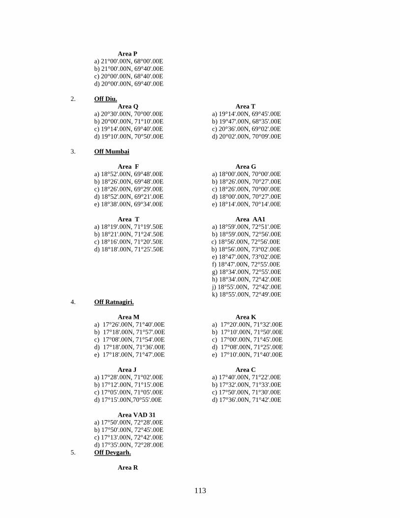
113
Area P a) 21°00'.00N, 68°00'.00E b) 21°00'.00N, 69°40'.00E c) 20°00'.00N, 68°40'.00E d) 20°00'.00N, 69°40'.00E 2. Off Diu. Area Q Area T a) 20°30'.00N, 70°00'.00E a) 19°14'.00N, 69°45'.00E b) 20°00'.00N, 71°10'.00E b) 19°47'.00N, 68°35'.00E c) 19°14'.00N, 69°40'.00E c) 20°36'.00N, 69°02'.00E d) 19°10'.00N, 70°50'.00E d) 20°02'.00N, 70°09'.00E
3. Off Mumbai Area F Area G a) 18°52'.00N, 69°48'.00E a) 18°00'.00N, 70°00'.00E b) 18°26'.00N, 69°48'.00E b) 18°26'.00N, 70°27'.00E c) 18°26'.00N, 69°29'.00E c) 18°26'.00N, 70°00'.00E d) 18°52'.00N, 69°21'.00E d) 18°00'.00N, 70°27'.00E e) 18°38'.00N, 69°34'.00E e) 18°14'.00N, 70°14'.00E Area T Area AA1 a) 18°19'.00N, 71°19'.50E a) 18°59'.00N, 72°51'.00E b) 18°21'.00N, 71°24'.50E b) 18°59'.00N, 72°56'.00E c) 18°16'.00N, 71°20'.50E c) 18°56'.00N, 72°56'.00E d) 18°18'.00N, 71°25'.50E b) 18°56'.00N, 73°02'.00E e) 18°47'.00N, 73°02'.00E
f) 18°47'.00N, 72°55'.00E g) 18°34'.00N, 72°55'.00E h) 18°34'.00N, 72°42'.00E j) 18°55'.00N, 72°42'.00E k) 18°55'.00N, 72°49'.00E
4. Off Ratnagiri. Area M Area K a) 17°26'.00N, 71°40'.00E a) 17°20'.00N, 71°32'.00E b) 17°18'.00N, 71°57'.00E b) 17°10'.00N, 71°50'.00E c) 17°08'.00N, 71°54'.00E c) 17°00'.00N, 71°45'.00E d) 17°18'.00N, 71°36'.00E d) 17°08'.00N, 71°25'.00E e) 17°18'.00N, 71°47'.00E e) 17°10'.00N, 71°40'.00E Area J Area C a) 17°28'.00N, 71°02'.00E a) 17°40'.00N, 71°22'.00E b) 17°12'.00N, 71°15'.00E b) 17°32'.00N, 71°33'.00E c) 17°05'.00N, 71°05'.00E c) 17°50'.00N, 71°30'.00E d) 17°15'.00N,70°55'.00E d) 17°36'.00N, 71°42'.00E Area VAD 31 a) 17°50'.00N, 72°28'.00E b) 17°50'.00N, 72°45'.00E c) 17°13'.00N, 72°42'.00E d) 17°35'.00N, 72°28'.00E 5. Off Devgarh. Area R
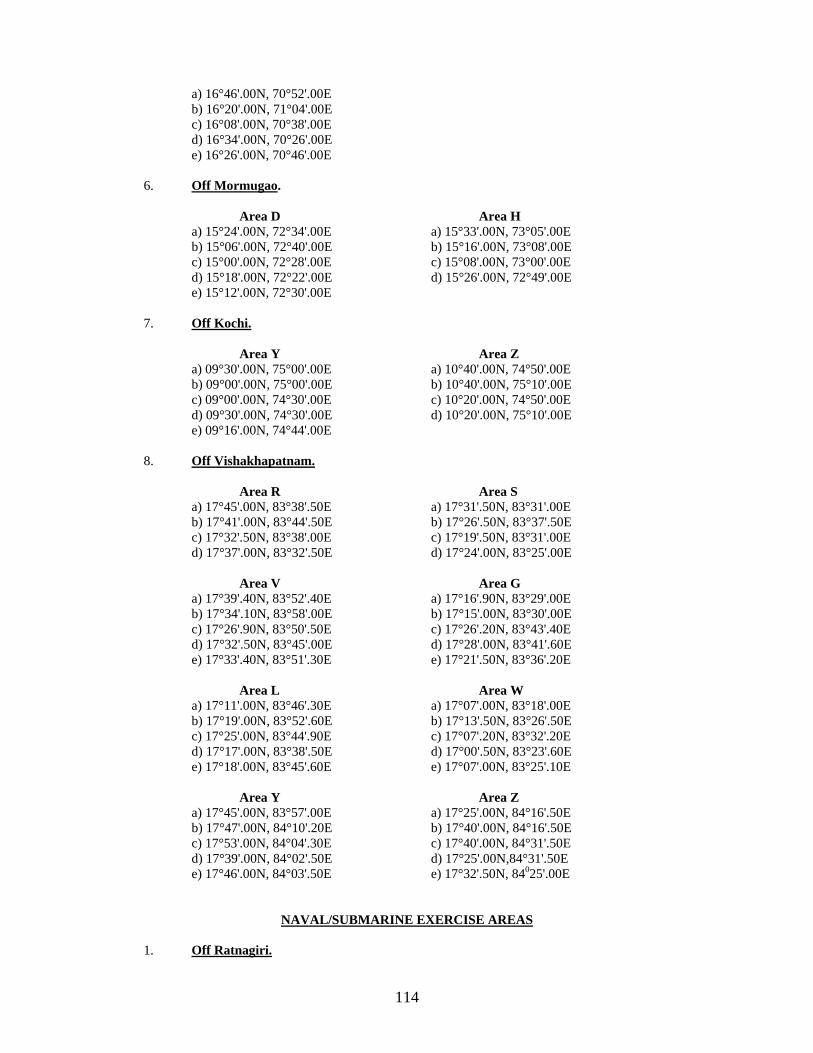
114
a) 16°46'.00N, 70°52'.00E b) 16°20'.00N, 71°04'.00E c) 16°08'.00N, 70°38'.00E d) 16°34'.00N, 70°26'.00E e) 16°26'.00N, 70°46'.00E 6. Off Mormugao. Area D Area H a) 15°24'.00N, 72°34'.00E a) 15°33'.00N, 73°05'.00E b) 15°06'.00N, 72°40'.00E b) 15°16'.00N, 73°08'.00E c) 15°00'.00N, 72°28'.00E c) 15°08'.00N, 73°00'.00E d) 15°18'.00N, 72°22'.00E d) 15°26'.00N, 72°49'.00E e) 15°12'.00N, 72°30'.00E 7. Off Kochi. Area Y Area Z a) 09°30'.00N, 75°00'.00E a) 10°40'.00N, 74°50'.00E b) 09°00'.00N, 75°00'.00E b) 10°40'.00N, 75°10'.00E c) 09°00'.00N, 74°30'.00E c) 10°20'.00N, 74°50'.00E d) 09°30'.00N, 74°30'.00E d) 10°20'.00N, 75°10'.00E e) 09°16'.00N, 74°44'.00E 8. Off Vishakhapatnam. Area R Area S a) 17°45'.00N, 83°38'.50E a) 17°31'.50N, 83°31'.00E b) 17°41'.00N, 83°44'.50E b) 17°26'.50N, 83°37'.50E c) 17°32'.50N, 83°38'.00E c) 17°19'.50N, 83°31'.00E d) 17°37'.00N, 83°32'.50E d) 17°24'.00N, 83°25'.00E Area V Area G a) 17°39'.40N, 83°52'.40E a) 17°16'.90N, 83°29'.00E b) 17°34'.10N, 83°58'.00E b) 17°15'.00N, 83°30'.00E c) 17°26'.90N, 83°50'.50E c) 17°26'.20N, 83°43'.40E d) 17°32'.50N, 83°45'.00E d) 17°28'.00N, 83°41'.60E e) 17°33'.40N, 83°51'.30E e) 17°21'.50N, 83°36'.20E Area L Area W a) 17°11'.00N, 83°46'.30E a) 17°07'.00N, 83°18'.00E b) 17°19'.00N, 83°52'.60E b) 17°13'.50N, 83°26'.50E c) 17°25'.00N, 83°44'.90E c) 17°07'.20N, 83°32'.20E d) 17°17'.00N, 83°38'.50E d) 17°00'.50N, 83°23'.60E e) 17°18'.00N, 83°45'.60E e) 17°07'.00N, 83°25'.10E Area Y Area Z a) 17°45'.00N, 83°57'.00E a) 17°25'.00N, 84°16'.50E b) 17°47'.00N, 84°10'.20E b) 17°40'.00N, 84°16'.50E c) 17°53'.00N, 84°04'.30E c) 17°40'.00N, 84°31'.50E d) 17°39'.00N, 84°02'.50E d) 17°25'.00N,84°31'.50E e) 17°46'.00N, 84°03'.50E e) 17°32'.50N, 84025'.00E
NAVAL/SUBMARINE EXERCISE AREAS
1. Off Ratnagiri.

115
Area UU a) 17°40'.00N, 71°14'.00E b) 17°25'.00N, 71°30'.00E c) 17°18'.00N, 71°16'.00E d) 17°30'.00N, 71°07'.00E
1. Off Goa. Area RR a) 16°08'.00N, 72°43'.00E b) 15°43'.00N, 72°51'.00E c) 15°37'.00N, 72°26'.00E d) 16°02'.00N, 72°19'.00E
1. Off Karwar. Area SS a) 14°36'.00N, 73°15'.00E b) 14°12'.00N, 73°24'.00E c) 14°04'.00N, 73°00'.00E d) 14°28'.00N, 72°52'.00E
STANDARD OPERATING AREAS
1. Off Vishakhapatnam. Area Z 1 Area Z 2 a) 17°38'.80N, 83°46'.50E a) 17°40'.20N, 83°44'.80E b) 17°33'.00N, 83°41'.00E b) 17°32'.60N, 83°38'.00E c) 17°34'.00N, 83°37'.00E c) 17°37'.20N, 83°32'.20E d) 17°41'.80N, 83°43'.00E d) 17°45'.00N, 83°39'.00E
Area Z 3 a) 17°26'.60N, 83°37'.50E
b) 17°18'.70N, 83°30'.60E c) 17°20'.30N, 83°27'.80E d) 17°28'.90N, 83°34'.70E
2. Off Kakinada.
Area Z 4
a) 17°03'.00N, 83°01'.50E b) 16°58'.50N, 83°03'.50E
c) 16°49'.00N, 82°44'.00E d) 16°52'.50N, 82°43'.50E
3. Off Quilon. Area Z 5
a) 9°05'.00N, 75°50'.00E b) 8°50'.00N, 75°59'.00E
c) 8°39'.00N, 75°31'.50E d) 9°01'.00N, 75°31'.00E

116
Special Notice No.10: CAUTION WITH REGARD TO SHIPS APPROACHING SQUADRONS, CONVOYS, AIRCRAFT AND OTHER WAR SHIPS AT SEA, AIRCRAFT CARRIERS AT ANCHOR AND VESSELS. Squadrons and Convoys 1. The attention of ship owners and mariners is called to the danger which is caused by a single vessel approaching a squadron of warships, or merchant vessels in convoy, so closely as to involve the risk of collision, attempting to pass ahead of, or through such a squadron or convoy. 2. A single vessel approaching squadron or convoy may be contacted by the senior ship/OTC to keep well clear of the formation. Mariners are, therefore, warned that a single vessel should adopt early measures to keep out of the way of a squadron or convoy. 3. Although a single vessel is advised to keep out of the way of a squadron or convoy, this does not entitle vessels sailing in company to proceed without regard to the movements of the single vessel. Vessels sailing in a squadron or convey should accordingly keep a careful watch on the movements of any single vessel approaching the squadron or convoy and should be ready, in case the single vessel does not keep out of the way, to take such action as will best aid to avert collision. Aircraft Carriers 4. Attention is also drawn to the uncertainty of the movements of ships operating aircraft and helicopter, which must usually turn into the wind when aircraft and helicopters are operating to or from their decks. 5. Furthermore, mariners are warned that, by night aircraft carriers have:- (a) Their steaming lights permanently off the center line of the ship and at considerably reduced
horizontal separation. (b) Alternative positions for their lights:- (i) on either side of the hull, (ii) on either side of the Island structure, in which case the port bow light may be as much
as 30 meters from the port side of the ship. 6. Certain aircraft carriers exhibit anchor light by displaying four white lights in the following manner:-
(a) In the forward of the vessel at a distance of not more than 1.5 meters below the flight deck, two lights in the same horizontal plane, one on the port side and one on the starboard side. (b) In the after part of the vessel at a height of not less than 4.6 meters lower than the forward lights, two lights in the same horizontal plane, one on the port side and one on the starboard side.
7. Each of the above lights is visible over an arc of at least 180°. The forward light visible over a minimum arc from one point on the opposite bow to one point from right astern on their own side and the after lights from one point on the opposite quarter to one point from right ahead on their own side. Replenishment at Sea 8. Naval ships in conjunction with auxiliaries frequently exercise Replenishment-at-Sea. While doing so two or more ships taking part are connected by jackstays and hoses. They display the signals prescribed by Rule 27 (b) of International Regulations for Preventing Collision at Sea, 1972.

117
9. Mariners are warned that while carrying out these exercises the ships are severely restricted both in maneuverability and speed. Other vessels are, therefore, advised to keep well clear in accordance with Rules 2 and 18 of the above Regulations. Certain Other Warships - Position of Steaming Lights 10. Certain other warships, which, in accordance with Rule 1 (e) of International Regulations for preventing Collisions at Sea. 1972, cannot comply fully with the provisions of sections 2 and 3 of Annex 1 to the above rule, comply as closely as possible. 11. The following are some of the important deviations from the provisions of Section 2 and 3 of Annex 1 to the above rule, with respect to the positioning of lights in certain warships:-
(a) Where two masthead lights are carried, the horizontal and vertical separation between the two may be less than the prescribed value.
(b) The height above the hull of all the lights may be less than the prescribed value. (c) Side lights may be positioned in front of the forward masthead light.
(d) The forward masthead light may be placed more than one quarter of the length of the vessel from
the stem. 12. In addition certain vessels of 50 meters or more in length, of the following category may not be fitted with a second masthead light:- (a) Frigates (b) Patrol vessels (c) SDBs (d) Landing Ships (e) Ocean Tugs (f) Ocean Minesweepers (g) Coastal Minesweepers (h) Boomworking vessels (j) Submarines (k) Survey Ships (l) Missile Boats (m) Missile Corvettes Survey Vessels Risk of Collision While Surveying 13. Survey vessels carrying out hydrographic or oceanographic work will display the signal prescribed in Rule 27 (b) of Regulations for Preventing Collisions at Sea, 1972. That is, at night, three all round lights in vertical line, the highest and lowest red and the middle white, or by day three black shapes in a vertical line, the highest and lowest of the shapes shall be balls and the middle one diamond. The ships may also show the International two letter group IR "I am engaged in submarine survey work. You should keep clear of me". 14. While carrying out surveying work, survey ships often have to run across the normal lines of traffic and may be towing instruments upto 500 meters astern which will restrict their manoeuvrability and ability to change speed or stop quickly. Other vessels are, therefore, advised to keep well clear in accordance with Rules 16 and 18 of the above Regulations, giving clearance of at least five cables if passing astern. The notice does not cater for vessels engaged in seismic survey. Ships Towing Arrays 15. Modern capital warships are fitted with 'Towed Array Sonars' which are streamed during anti-submarine operations. These sonar arrays, when towed, extend upto 2 km behind the towing ship. 16. Mariners are, therefore, advised to exercise caution and give appropriate wide berth when approaching capital warships.

118
Special Notice No.11: INFORMATION CONCERNING SUBMARINES.
Part I - Warning Signals 1. Mariners are warned that considerable hazard to life may result by the disregard of the following warning signals, which denote the presence of submarines: - (a) Visual Signals
(i) Indian Vessels fly the International Code Group NE 2 to denote that submarines, which may be submerged, are in the vicinity. Vessels should steer so as to give a wide berth to any vessel flying this signal. If for any reason it is necessary to approach her, vessels should approach at low speed and a good lookout must be kept for submarines whose presence may be indicated only by their periscope or other masts showing above water. (ii) A submarine submerged at a depth too great to show her periscope, may sometimes indicate her position by releasing a "SSE (Submerged Signal Ejector)" or “Smoke candle” which gives off a flare/smoke on first reaching the surface. Her position may sometimes be indicated by red-and-white or red-and-yellow buffs or floats, which are fitted low on the surface, close astern. (iii) Shishumar Class of Submarines - Identification light: In order to enable accompanying vessels to identify the position of a dived Shishumar Class of submarine the identification light is provided in the aft section of the conning tower. This light emits a white light upward through plexi glass and has a luminous range of 7 miles when measured in the air during clear visibility.
(iv) All vessels transiting through areas promulgated as Naval Exercise Areas are to bear in mind that submerged/partly submerged submarines are likely to be encountered. As far as possible such vessels are not to switch off navigation lights and stop propulsion whilst within these areas. (v) Movement of oil rigs outside offshore development areas is to be promulgated at least 48 hours prior to their movement for safety of submarine operations.
(vi) Promulgation of areas for seismic survey should as far as possible be clear of recommended routes to permit greater flexibility of dived submarine operations.
(b) Pyrotechnics and Smoke Candles. A Submerged Submarine in a Submarine Exercise area uses the
following signals: - Signal Signification (i) Red grenades/flares fired Keep clear. I am carrying out emergency in quick succession . surfacing procedure. Do not stop propellers. Ships are to clear the area immediately and standby to render assistance. (ii) Two coloured grenades/ Keep clear. My position is as indicated. I flares 3 minutes apart. intend to carryout surfacing procedure. Do The colour of the not stop propellers. Ships are to clear the grenades/flares may be white immediate vicinity. Yellow or Green. 2. It must not be inferred from the above that Submarines exercise only when in company with escorting vessels.

119
3. The legend "Submarine Exercise Area" shown on certain charts should not be taken to mean that Submarines do not exercise outside such areas. Under certain circumstances a Local Coast Radio Station may broadcast warnings that Submarines are exercising in specified areas. 4. The accompanying diagrams show Sonobuoy DSTV - 2C, Aircraft Float, Smoke and Flame markers. Sonobuoy are dropped from aircraft to detect submarines and may be encountered anywhere at sea. Other countries have similar Sonobuoys but their colour and dimensions are not known.
Part II Navigational Lights 5. Submarines are likely to be met on surface by night on approaches to Mumbai, Vishakhapatnam, Kochi, Chennai,Goa, Karwar, Porbandar, Kakinada, Port Blair and Tuticorin. Meeting submarines on surface during approaches to other ports cannot be ruled out. 6. The masthead and sidelights of IN submarines are placed well forward and very low over the water in proportion to the length and tonnage of these vessels. The steaming lights, bow lights and overtaking lights are closely spaced and as a result they give no indication of the submarines length, her course or a change of course. The stern lights are placed very low and may at times be partially obscured by sea spray and wash. The stern lights are invariably lower than the sidelights. 7. In summary the overall arrangement of the submarine navigational lights is unusual and may give the impression of markedly smaller and shorter vessels than they truly represent. Some submarines are fitted with a very quick yellow (amber) anti collision light. These lights flash at between 90 and 105 flashes per minute and are fitted 1 to 2 m above or below the masthead light. They should not be confused with a similar light exhibited by hovercraft with a rate of 120 flashes or more per minute. Part III - Sunken Submarine 8. A bottomed Submarine, which is unable to surface, will try to indicate her position by the following methods: - (a) Releasing an indicator buoy as soon as the accident occurs.
(b) Firing of Green/Red/Yellow SSEs(Submerged Signal Ejector). It should be remembered that it might not be possible for the submarine to continuously to fire her SSE. Correspondingly, a partially flooded submarine may only have certain number of SSE and the searching ship should not therefore expect many to appear.
(c) Pumping out oil, fuel or lubricating oil. (d) Releasing air bubbles. (e) Blowing of gash/other floats am. (f) Firing of MG 34/SFD (g) Transmitting on UWT, main sonar, and distress sonar/distress after running echo sounder and hull tapping.
9. Since oil streaks or debris may be the only indication of the presence or whereabouts of the Sunken Submarine, it is vitally important that surface ships refrain from discharging anything which might appear to have come from a submarine while they are in the submarine probability area. Searching ships and aircraft can waste many valuable hours investigating these false contacts. 10. In any submarine accident, time is the most vital factor affecting the chances of rescue of survivors and as the sighting of an indicator buoy may be the first indication that an accident has in fact occurred, it is vital that no time should be lost in taking action. 11. At any time after a submarine accident, survivors may start attempting to escape. Conditions inside are likely to deteriorate rapidly and postponement of escape will only be made in order to allow the rescue ships to reach the scene. Any ship finding a moored Submarine Indicator Buoy should not therefore leave the position but should standby well clear ready to pick up survivors. The latter will ascend nearly vertically, and it is important that plenty of sea room is given to enable them to do so safely. On arrival on the surface, men may be exhausted or ill,

120
and if circumstances are favourable, the presence of a boat already lowered is very desirable. Some men may require a recompression chamber and it will therefore, be the aim of the Naval authorities to get such a chamber to the scene as soon as possible. To sum up, the aims of a Submarine Rescue Operation are:- (a) To fix the exact position of the Submarine.
(b) To get a ship standing by to pick up survivors, if practicable with boats already lowered. (c) To get medical assistance to survivors picked up.
(d) To get a diver's re-compression chamber to the scene in case this is required by those seriously ill after being exposed to great pressure.
(e) To inform the trapped men that help is at hand. Submarine Indicator Buoy 12. I.N. Submarines are fitted with two different types of indicator buoys carried by Shishumar and Sindhughosh class of submarines respectively. The physical dimensions, identifying marks and distress facilities of these buoys are described briefly in the succeeding paragraphs. Emergency Indicator Buoy - Sindhughosh Class of Submarines 13. The diameter of the buoy is 115 cms. The buoy is painted in 4 quadrants. Alternate quadrants are painted yellow and orange. The identification number of the Submarine is painted on the buoy. The buoy has a white flashing light flashing every 3 seconds. A powered telephone (from the batteries of the submarine) is fitted on top for two-way communication with the submarines. Two-way radiotelephony communication can be established with the submarine on 121.5 MHz when the buoy is recovered. A radio beacon transmitting at 51.2 MHz (continuous or transmitting for 20 seconds with a pause of 60 seconds) is fitted on the buoy. Emergency Indictor Buoy - Shishumar Class of Submarines 14. The buoy is made of expanded plastic foam covered with GRP skin for physical protection. The buoy is semi spherical in shape, 76 cms in diameter and 90 cms high. The buoy floats end up with a freeboard of about 15 cms. It is covered with longitudinal strips of reflective tape alternative red and white. A 3-digit identification number is displayed on each side of ultra violet light flashing centre of the top surface. In darkness and good weather the unassisted visibility of the light is 5 miles. The buoy carries HF and UHF whip aerial (168 cms and 100 cms long respectively). The transmitters are automatically activated when the indicator buoy is released. The HF Transmission frequency of 8364Khz contains the international distress call, SOS together with the submarine identification number. The UHF Sarbe tone is transmitted at a frequency of 243 MHZ. No two-way telephone communication with the submarine is possible. The indicator buoy is also equipped with an emergency ‘Xenon’ light flashing at 32 flashes per minute with a range of approx 5 nm in good visibility conditions. 15. The finder of any of these buoys should inform the nearest Naval/ Coastguard// Port/Police authorities and should not attempt to secure to or lift the buoy. The accompanying diagram shows the Submarine Indicator Buoy.

121
To accompany Notices to Mariner No. 11

122
To accompany Notices to Mariner No. 11

123
To accompany Notices to Mariner No. 11

124
To accompany Notices to Mariner No. 11

125
To accompany Notices to Mariner No. 11
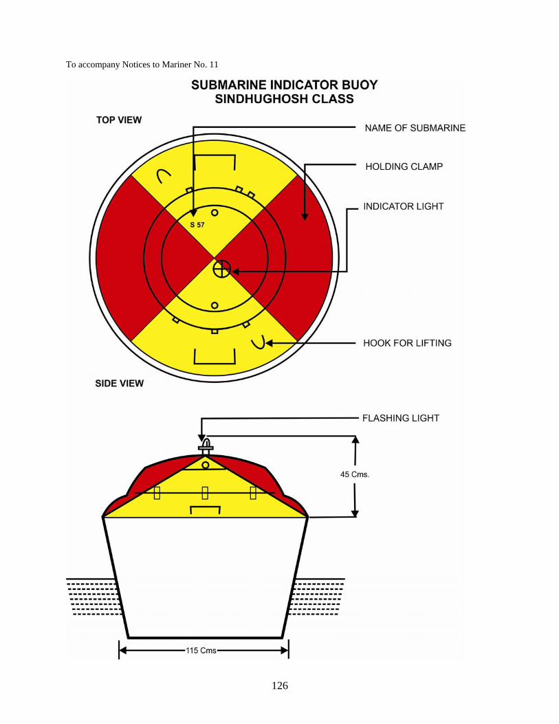
126
To accompany Notices to Mariner No. 11

127
Special Notice No. 12: RADIO NAVIGATIONAL WARNINGS Source: Joint IMO MSI Manual S53, IMO NAVTEX Manual 1. This Notice contains information concerning navigational warnings under the World Wide Navigational Warning Service (WWNWS). Navigational warnings are issued in response to SOLAS regulation V/4 and carry information which may have a direct bearing on the safety of life at sea. There are four types of navigational warnings: NAVAREA warnings, Sub-Area warnings, coastal warnings and local warnings. 2. Methods of broadcast. Two principal methods are used for broadcasting maritime safety information in accordance with the provisions of the International Convention for the Safety of Life at Sea, 1974, as amended, in the areas covered by these methods, as follows:- (a) NAVTEX: broadcasts to coastal waters; and (b) SafetyNET: broadcasts which cover all the waters of the globe except for Sea Area A4 (Polar Regions) 3. NAVAREA Warnings. NAVAREA warnings are concerned with the information detailed below which ocean-going mariners require for their safe navigation. This includes, in particular, new navigational hazards and failures of important aids to navigation as well as information which may require changes to planned navigational routes. The following subjects are considered suitable for broadcast as NAVAREA warnings. This list is not exhaustive and should be regarded only as a guideline. Furthermore, it presupposes that sufficiently precise information about the item has not previously been disseminated in a Notice to Mariners:-
(a) Casualties to lights, fog signals, buoys and other aids to navigation affecting main shipping lanes; (b) The presence of dangerous wrecks in or near main shipping lanes and, if relevant, their marking;
(c) Establishment of major new aids to navigation or significant changes to existing ones when such establishment or change, might be misleading to shipping;
(d) The presence of large unwieldy tows in congested waters;
(e) Drifting hazards (including derelict vessels, ice, mines, containers, other large items, etc.);
(f) Areas where search and rescue (SAR) and anti-pollution operations are being carried out (for avoidance of such areas);
(g) The presence of newly discovered rocks, shoals, reefs and wrecks likely to constitute a danger to shipping, and, if relevant, their marking;
(h) Unexpected alteration or suspension of established routes;
(j) Cable or pipe-laying activities, the towing of large submerged objects for research or exploration purposes, the employment of manned or unmanned submersibles, or other underwater operations constituting potential dangers in or near shipping lanes;
(k) The establishment of research or scientific instruments in or near shipping lanes;
(l) The establishment of offshore structures in or near shipping lanes;
(m) Significant malfunctioning of radio-navigation services and shore-based maritime safety information radio or satellite services;

128
(n) Information concerning special operations which might affect the safety of shipping, sometimes over wide areas, e.g., naval exercises, missile firings, space missions, nuclear tests, ordnance dumping zones, etc. It is important that where the degree of hazard is known, this information is included in the relevant warning. Whenever possible such warnings should be originated not less than five days in advance of the scheduled event and reference may be made to relevant national publications in the warning;
(p) Acts of piracy and armed robbery against ships; (q) Tsunamis and other natural phenomena, such as abnormal changes to sea level; (r) World Health Organization (WHO) health advisory information; and
(s) Security-related requirements 4. Structure of NAVAREA warning NAVAREA warnings are consecutively numbered throughout the calendar year, commencing with 001/YY at 0000 UTC on 01 January. All NAVAREA warnings shall be broadcast only in English in the International NAVTEX and SafetyNET services in accordance with IMO resolution A.706 (17), as amended. The minimum information which a mariner requires to avoid danger is HAZARD & POSITION. Amplifying remarks may be included in order to provide sufficient extra details to clearly identify the significance of the hazard and to assist mariners in recognizing and assessing its effect upon their navigation. The time, date and duration of the event shall be included if known. The text of a navigational warning shall contain specific message elements, identified and ordered by the reference numbers shown below:-
Part Reference Number Message Element
Preamble
1 Message series identifier
2 General Area
3 Locality
4 Chart Number
Warning
5 Key subject
6 Geographical position
7 Amplifying remarks
Post Script 8 Cancellations details
NAVTEX

129
5. Broadcast of Navigational Warnings by NAVTEX. NAVTEX is an international automated direct-printing service for promulgation of navigational and meteorological warnings, meteorological forecasts and other urgent information to ships. It was developed to provide a low-cost, simple and automated means of receiving maritime safety information on board ships at sea in coastal waters. NAVTEX provides shipping with navigational and meteorological warnings and urgent information through automatic printouts from a dedicated receiver. NAVTEX is a component of the IMO/IHO Worldwide Navigational Warning Service (WWNWS) defined by IMO Assembly resolution A.706 (17). It has also been included as an element of the Global Maritime Distress and Safety System (GMDSS). Since 1 August 1993, NAVTEX receiving capability has become part of the mandatory equipment which is required to be carried in certain vessels under the provisions of the International Convention for the Safety of Life at Sea (SOLAS). 6. Definitions.
(a) International NAVTEX service means the co-ordinated broadcast and automatic reception on 518 kHz of maritime safety information by means of narrow-band direct-printing telegraphy using the English language.
(b) National NAVTEX service means the broadcast and automatic reception of maritime safety information by means of narrow-band direct-printing telegraphy using frequencies other than 518 kHz and languages as decided by the Administration concerned.
(c) NAVTEX means the system for the broadcast and automatic reception of maritime safety information by means of narrow band direct-printing telegraphy. This may include inland seas, lakes and waterways navigable by seagoing ships
7. Principal Features of NAVTEX. NAVTEX transmissions are sent via a single frequency from local stations situated worldwide. The power of each transmission is regulated so as to avoid the possibility of interference between transmitters. Users can set their NAVTEX receivers to receive specific message types and reject others. Messages such as navigational and meteorological warnings and search and rescue information are non-rejectable to ensure that ships equipped with NAVTEX always receive the most vital information. Users can choose to receive information from the single transmitter that serves the sea area around their position, or from a number of transmitters. NAVTEX coordinators exercise control of messages transmitted by each station according to the information contained in each message and the geographical coverage required. Thus a user may choose to accept messages either from the single transmitter which serves the sea area around his position, or from a number of transmitters as appropriate. Ideally, the user should select the station within whose coverage the vessel is currently operating and the station into whose coverage area the vessel will transit next. 8. Language and National Broadcast Options. International NAVTEX Service messages on 518 kHz shall be broadcast only in English. There is often a requirement for NAVTEX broadcasts to be made in national languages in addition to English. This shall only be achieved by the provision of a national NAVTEX service. National NAVTEX services use frequencies other than 518 kHz, and languages as decided by the Administrations concerned. These National NAVTEX services may be broadcast on 490 kHz or 4209·5 kHz, or on an alternative nationally assigned frequency 9. Message Content. Examples of the content and layout of NAVTEX messages are shown in the Joint IMO/IHO/WMO Manual on Maritime Safety Information. This publication should be available to all personnel responsible for the drafting of messages to be broadcast by NAVTEX stations. 10. Message Priorities in the International NAVTEX Service. The message originator is responsible for assessing the urgency of the information and inserting the appropriate priority marking. One of the following three message priorities is used to dictate the timing of the first broadcast of a new warning in the NAVTEX service. In descending order of urgency:-

130
(a) VITAL for immediate broadcast, subject to avoiding interference to ongoing transmissions. Such messages shall also be passed to the appropriate NAVAREA Coordinator for possible transmission as a NAVAREA message via SafetyNET;
(b) IMPORTANT for broadcast at the next available period when the frequency is unused; and
(c) ROUTINE for broadcast at the next scheduled transmission.
11. Both VITAL and IMPORTANT messages shall be repeated, at least once at the next scheduled transmission time slot, if the situation is still extant. The message priority is a procedural instruction for the NAVTEX Coordinator or the transmitting station and shall not be included in the message. By selecting the appropriate priority of VITAL, IMPORTANT or ROUTINE at the transmission terminal, the message will be broadcast with the correct priority. In order to avoid unnecessary disruption to the service, the priority marking VITAL is to be used only in cases of extreme urgency, i.e. to relay an initial shore-to-ship distress-related message or acts of piracy warnings, tsunamis and other natural phenomena warnings. In addition, VITAL messages are to be kept as brief as possible. The information provider is responsible for ensuring that the NAVTEX Coordinator is fully and immediately aware when a message shall be broadcast with the priority of VITAL. VITAL messages will normally be broadcast using NAVTEX number B3B4 = 00.

131
12. Overview of TECHNICAL CHARACTERS B1, B2, B3, B4. NAVTEX messages include instructions to the NAVTEX receiver for processing maritime safety information in the form of the NAVTEX message identity, which consists of four technical "B" characters which make up an alphanumeric code. The technical "B" characters which make up the full NAVTEX message identity is as shown in the Table I below.
B1 Transmitter
Identification Character
B2 Subject Indicator Character
B3, B4 Message Numbering
Character 1 letter 1 letter 2 digit A to X A = Navigational warning 01 to 99
(Message numbering characters
“00” are not to be used for routine message)
B = Meteorological Warning C = Ice report D12 = Search and Rescue nformation, acts of piracy warnings, tsunamis and other natural phenomenas E = Meteorological forecast F = Pilots and VTS service messages
G = AIS Service Messages (non navigational aid)
H = LORAN Message I = currently not used J = GNSS message K = Other electronic navigational aid system messages L = Other navigational Warnings-additional to B2 Character A13
M = N= O= P= Q= R= S= T= U=
Currently not used
V= W= X= Y=
Special services Allocati--on by the IMO NAVTEX Co-ordinating
panel
Z = No message on hand
Table I – Technical "B" characters which make up the full NAVTEX message identity

132
13. Message Format . NAVTEX messages must be composed in accordance to the guidelines contained in the Joint IMO/IHO/WMO Manual on Maritime Safety Information and IHO Publication S-53. The basic elements of the NAVTEX message is as shown in the table II below:-
Element Example Phasing signal Start of message group ZCZC One space NAVTEX message identity FA01 Carriage return + line feed Message content (Date Time Group – Optional e.g. 040735 UTC OCT 10)
ENGLISH CHANNEL. START POINT SOUTHWARD. CHART BA 442(INT 1701). UNEXPLODEDORDANANCE LOCATED 49-51.97N 003-39.54W AND 49-55.24N 003-40.79W
End of message instruction NNNN Carriage return + two line feed Phasing signal
Table II Basic Message Elements 14. B1 – Transmitter Identification Character. The transmitter identification character is a single letter which is allocated to each transmitter. It is used to identify the broadcasts which are to be accepted by the receiver and those to be rejected, and also the time slot for the transmission. In order to avoid erroneous reception and interference of transmissions from two stations having the same transmitter identification character, it is necessary to ensure that such stations have a large geographical separation. Allocation of transmitter identification characters by alphabetical sequence to adjacent sites can also cause problems; hence, consecutive transmitter identification characters are not normally allocated to adjacent stations. Experience has shown that this removes the risk of a station which over-runs its time slot masking the phasing signal of an adjacent station which is about to begin its transmission. NAVTEX transmissions have a designed maximum range of about 400 nautical miles. The minimum distance between two transmitters with the same transmitter identification identifier must, therefore, be sufficient to ensure that a receiver cannot be within range of both at the same time. 15. B2 – Subject Indicator Character . Information is grouped by subject in the NAVTEX broadcast and each subject group is allocated a B2 subject indicator character. The subject indicator character is used by the receiver to identify the different classes of messages as listed in Table 9.1 in para 9.60. Some subject indicator characters can be used to reject messages concerning certain subjects which may not be required by the ship (e.g., LORAN messages may be rejected by deselecting the B2 subject indicator character H on the NAVTEX receiver on board a ship which is not fitted with a LORAN receiver). Reception of messages, transmitted using subject indicator characters A, B, D and L, which have been allocated for navigational warnings, meteorological warnings, search and rescue information, acts of piracy warnings, tsunamis and other natural phenomena, is mandatory and cannot be deselected on the NAVTEX receiver. This has been designed to ensure that ships using NAVTEX always receive the most essential information. 16. B3, B4 – Message Numbering Characters (NAVTEX Number). Each message within each subject group, is allocated a two digit sequential serial number, beginning at 01 and ending at 99. The B3B4 message numbering characters together, are often referred to as the "NAVTEX number". The NAVTEX number is solely allocated as a component of the NAVTEX message identity and should not be confused with (and bears no correlation to), the series identity and consecutive number of the NAVAREA or Coastal warning contained in the message. Messages broadcast using NAVTEX number B3B4 = 00 cannot be rejected and will automatically override any selection of B1 transmitter identification characters as well as any B2 subject indicator characters selected on the NAVTEX receiver. Use of NAVTEX number B3B4 = 00 must therefore be strictly controlled, since messages carrying it will always be printed or displayed every time they are received. Routine messages and service messages must never be allocated B3B4 = 00. The correct use of B2 characters A, B, D and L, will ensure that messages containing safety information will always be printed or displayed on first receipt. Each message within

133
each subject group is allocated a two digit sequential serial number, beginning at 01 and ending at 99. The B3B4 message numbering characters together, are often referred to as the "NAVTEX number". 17. NAVTEX Coverage. The status of NAVTEX Service Areas within NAVAREA VIII is as shown below:-
18. NAVTEX Chain. Seven new NAVTEX stations are being established along the Indian coast and island territory. The preparation of technical specifications and system architecture for the NAVTEX Chain is being undertaken. The system is likely to be operational by end 2013. The details of the proposed NAVTEX Stations are as tabulated below:-
SL NO LOCATION REMARKS
(i) Veraval, Gujarat
India, West Coast (ii) Vengurla, Maharashtra
(iii) Muttam Point, (Tamil Nadu)
(iv) Porto Novo, (Tamil Nadu)
India, East Coast (v) Vakalpudi , (Andhra Pradesh)
(vi) Balasore(Orissa)
(vii) Keating Point Andaman & Nicobar Islands, India
19. World Wide Radio Navigational Warning Service (WWNWS). The maritime safety information sevice of the GMDSS is the internationally and nationally coordinated network of broadcasts containing information which is necessary for safe navigation, received in ships by equipment which automatically monitors the appropriate transmissions, displays information which is relevant to the ship and provides a print capability. The World-Wide Navigational Warning Service (WWNWS) means the internationally and nationally coordinated service for the promulgation of navigational warnings. The world has been divided into twenty one (21) definite geographical sea areas named as NAVAREAs by the International Maritime Organisation (IMO) for the purpose of promulgating radio navigational warnings under the World Wide Navigational Warning Service (WWNWS). The Chief Hydrographer to the Govt. of India has been nominated as the coordinator of NAVAREA VIII region which generally encompasses the Indian Ocean Region (IOR) including the Bay of Bengal and is authorized to provide search and rescue information for broadcast by the IMO. The delimitation of NAVAREAS for coordinating and promulgating radio navigational warnings under the World-Wide Navigational Warning Service is depicted in Annexure ‘A’ to this notice. The delimitation of such areas is not related to and shall not prejudice the delimitation of any boundaries between States.
Station Position Tel/Fax/Email Schedule Range NM Status
Mumbai, India(G)
19°05´N 72°50´E
+912224332554 0230,0630,1030, 1430,1830,2230
250 Temporarily out of operation
Chennai, India(P)
13°05´N 80°17´E
+914425240500 0100,0500,0900, 1300,1700,2100
250 Temporarily out of operation
Cassis, Mauritius (C)
20°10´S 57°28´E
+2302085950(T) +2302110838(F) [email protected]
0020,0420,0820, 1220,1620,2020
400 Operational

134
20. Broadcast of NAVAREA Warnings. Details of NAVAREA broadcast for all NAVAREAs are given in ILRS Volume 5. NAVAREA VIII warnings are broadcast from Pune LES, daily 1000hrs and 2200 hrs UTC through INMARSAT. In case of any urgent information or emergency, they can be transmitted at any time. All in force NAVAREA VIII warnings are broadcast through SafetyNET via LES Pune for six weeks until cancelled. The NAVAREA warnings are forwarded to the following agencies for promulgation/broadcast:-
(a) COMNETCEN (Mumbai):- For transmission to IN Ships
(b) Director, Pune LES: - For transmission through GMDSS, in accordance with International Safety Net Manual.
All NAVAREA warnings in force are also uploaded on the official website of National Hydrographic Office www.hydrobharat.nic.in and are available at the following link: http://www.hydrobharat.nic.in/navarea_warnings_in_force.pdf 21. NAVAREA VIII Coordinator Contact Details. The Chief Hydrographer to the Government of India is the NAVAREA VIII Coordinator. The Chief Hydrographer shall be the central point of contact for all matters concerning to NAVAREA warnings including the monitoring of their broadcasts and to ensure that the messages originated have been correctly transmitted. He is to coordinate with the National Coordinators of the countries within the NAVAREA VIII for the collection of navigational information and promulgation of suitable warnings The contact details of NAVAREA VIII Coordinator is as follows:-
The Chief Hydrographer Attn: Joint Director of Hydrography (Maritime Safety Information Services) National Hydrographic Office 107-A, Rajpur Road P.B. No. 75, Dehradun, Uttarakhand India Pin 248 001 Tel: +91 135 2747365 Fax: +91 135 2748373 E-mail: [email protected] [email protected] Web site: www.hydrobharat.nic.in

135
(Appendix A) (Refers to Para 20)
Delimitation of NAVAREAS under WWNWS

136
Special Notice No.13: SUBMARINE CABLES Source: www.cableawareness.info, www.iscpc.org
1. Damage to Submarine Cable. Modern high capacity repeated type submarine cables now cross the oceans and major seas of the world. Cables of increasing capacity are being designed and will continue to be laid for many years to come. Towing of fishing gears, anchoring close or over the submarine cables and various other activities on the seabed could very easily damage a cable and cause major interruption to global communications with very serious consequences. 2. Avoid Cables From Damage. Considering the possibility of positioning inaccuracies and repaired cables section deviations, the fishing community are advised to keep towed gear a minimum distance of one nautical mile from either side of charted cables. For safe navigation and the avoidance of vital submarine cables, the most recent charts should always be available on the fishing vessel. The submarine cables are clearly identified on all charts used for navigation. The international symbol for an active submarine cable is a wavy line coloured magenta or black. In general the accuracy with which cables are laid varies inversely to the distance from land Navigation on cable ships is of a high standard but is limited to the techniques available when the cable was installed. Cables laid in the early 1970s, before satellite navigation became commonplace could be up to one nautical mile (nm) out of charted position. With the use of satellites and other sophisticated navigational electronic aids, the positional accuracy of recently-laid cables is usually better than 0.5 nm. However despite this high accuracy during laying, the cable may now be re-laid away from the original charted position due to cable repairs having been required subsequent to the original cable lay. 3. Caution against Anchoring and Trawling in vicinity.
(a) Cautionary Note or the legend “Submarine Cable Area” appears on many charts, calling the attention of the mariners to the areas in which there are submarine cables. (b) Every care should be taken to avoid anchoring and trawling in such areas even though there may be no specific prohibition against doing so, in view of the serious interference with communications which results from damage to submarine cables. (c) Equal care should be taken wherever the symbols for submarine cables are shown on the chart.
4. Danger Involved in Cutting to Clear Anchors or Fishing Gear. In the event of any vessel fouling a submarine cable, every effort should be made to clear the anchor or gear by normal methods without causing damage. If these efforts fail, the anchor or gear should be slipped and abandoned without attempting to cut the cable. Very high voltage are fed into certain submarine cables and serious risk of loss of life exists due to electric shock, or at least of severe burns, if any attempt to cut the cable is made. Particular care should be exercised should a vessel’s trawl/fishing gear foul and raise it from seabed. This may lead to a capsize situation due to the excessive load. No claim in respect of injury or damage sustained through such interference with a submarine cable would be entertained by the owners of cable.
5. Action Taken When Suspected Foul of a Submarine Cable.
(a) If weights are excessive and you suspect you are fast to a cable, DO NOT endanger your vessel and crew by attempting to recover your gear.
(b) Carefully plot your ship's position as accurately as possible, checking for any cables that may be close to your position.
(c) Advise your coast guard station of your situation OR if your coast guard is not obtainable call the emergency number of the cable maintenance company concerned and state that an incident is occurring concerning an underwater or Submarine Telecommunications cable.

137
6. (a) Charts showing cables positions are available from many Hydrographic Offices and the universal charting of cables has been endorsed by International Hydrographic Organisation.
(b) For more information on submarine cables, including related and regulations and charting policy, refer to the Mariners Handbook (BA NP 100, 8th edition). Further information can be found on the website of the International Cable Protection Committee at www.iscpc.org.
138
Special Notice No. 14: INDIAN MERCHANT SHIPS – USE OF RADAR IN THE TIME OF EMERGENCY OR WAR 1. Pending the receipt of details instructions, Masters of Indian Merchant Ships on the outbreak of war or emergency should be guided by following principles:-
(a) When at Sea. Unrestricted use of radar under all occasions. (b) When in an Indian Harbour. To cease operating radar, except when ship is under way and if so authorised by the local Naval Authorities.
139
Special Notice No. 15: INSTRUCTIONS REGARDING RENDERING REPORTS OF SHOALS OBTAINED BY ECHO SOUNDING 1. Each year numerous reports of shoal soundings are received by the Chief Hydrographer to the Govt. of India, but a large proportion of these have to be discarded as insufficient information is forwarded with them. 2. It may not be generally realized that false soundings may be obtained from incorrectly adjusted echo sounder (E/S) sets due to one of the following causes:-
(a) The returning echo being received after the transmission interval has been completed once or perhaps twice. (b) Dense shoals of fish layers of plankton which sometime gives an echo completely masking that from the bottom. Such a layer of is usually known as a “deep scattering layer” and is often found to rise toward the surface, at dusk and after remaining during the night close to the surface, descends again at drawn. The deep scattering layer frequently encountered at or near the edge of the continental shelf and frequently mistaken for shoal water. An example of the deep scattering layer which appears to pass through the sea bed recorded on 2nd transmission is shown in the accompanying Figure No.1 (c) Layer of water of different temperature, density or salinity from that of the surrounding water can sometimes give false echoes. (d) Strong tidal streams or eddies with solid particulars in suspension which may give a feathery echo. (e) It is possible in the more powerful type of E/S sets now in use that double echoes may be obtained even in the depths of several hundred metres. The second echo caused should be taken when phasing and using the on/off switch, as described above, that in fact the true echo is being recorded. The second echo is invariably weaker than the first and can be faded by turning down the sensitivity of the receiver.
3. When unexpected shoal soundings are obtained in waters where the charted depth gives no indication, even though discoloured water may be seen, the only certain method of confirmation of their existence is by taking a cast with the lead. 4. Where, however, the charted depth is nowhere more than the scale reading of the set and the shoal is seen to rise from the bottom of the trace, provided the speed and setting of the set are correct, the shoal sounding may be accepted unconditionally. 5. When report of the shoal soundings are received at the National Hydrographic Office, they are carefully considered in the light of accompanying documents or other evidence before any action is taken to amend charts. 6. In order that the Chief Hydrographer to the Govt. of India can make full use of the report of sounding, the Echo Trace should always be forwarded together with Form IH 102 (Hydrographic Note). Navigating officers are requested to note the following points regarding essential details:-
(a) Draw a line across the trace (or mark the trace by pressing the fix push, if fitted) each time a fix is taken and at a number of intermediate points at set time intervals. (b) Insert a number of each fix and the time at each line. (The time is important since the height of the tide must subsequently be applied in order to obtain the correct depth). (c) Insert the date of observation. (d) Insert recorded depth of all peak soundings. (e) Mark the phase or scale range in which the set is running noting particularly when a change is made.

140
(f) Insert the make and type of Echo Sounding Machine and the scale width. Examples of correctly marked Echo Traces are shown in the accompanying Figure 2.
7. It is important to note that the draught of the ship should be the same as the depth of the transmission line. If the latter is set to zero, a note to this effect should be made on the trace giving the draught of the ship. 8. In sets which have two operating speeds (e.g. metres and decimetres, or metresX10) the transmission lines must be separately adjusted to show the correct scale reading in each speed. 9. In the case of deep soundings greater than 182.9m it is important that the E/S speed (Speed Velocity) in metres per seconds should be checked and stated. It should also be stated whether or not soundings have been corrected from BA publication NP 139- Echo Sounding Correction Tables. 10. Attention is drawn to supplement to B.A. publication HD-282 ECHO SOUNDING. Errors, adjustments and reporting which can be obtained from British Admiralty Chart Agents.

141
(Refers to para 2)
Fig 1: Deep Scattering Layer
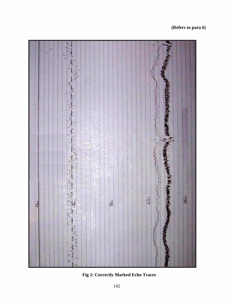
142
(Refers to para 6)
Fig 2: Correctly Marked Echo Traces

143
Special Notice No. 16: NATIONAL DATA BUOY PROGRAMME Source: www.niot.res.in
1. The collection of time series observation of oceanographic and meteorological parameters over Indian Seas are necessary to improve oceanographic services and predictive capability of short term and long term climatic changes as well to increase the understanding on ocean dynamics. Considering the importance of ocean observations to the country like India having a long coastline of about 7500 km and a vast oceanic area of 2.02 million sq. km of EEZ available for exploitation, Ministry of Earth Sciences, Government of India has established the Ocean observation Systems (erstwhile National Data Buoy Programme) in 1997 at National Institute of Ocean Technology (NIOT) Chennai with the following objectives:
(a) To collect marine meteorological and oceanographic data using moored Met-Ocean buoy systems and disseminate data to Indian National Centre for Ocean Information Services (INCOIS). (b) To collect water level data in deep sea using Bottom Pressure Recorder and disseminate data to INCOIS for Tsunami Early Warning System.
Under this programme, a network of buoys (Met Ocean, OMNI and Tsunami) have been deployed and maintained.

144
2. Buoys Feature. These moored offshore floating platforms are fitted with meteorological and oceanographic sensors, to measure in-situ observations. The observed data is then transmitted through satellite to the state-of-the-art shore station facility at NIOT, Chennai. Buoys are of three types viz. Met Ocean Buoy, OMNI Buoy and Tsunami Buoy. These buoys are equipped with global positioning system, beacon light, satellite transceiver, radar reflector and are powered by lithium batteries. The data buoys are moored at a depth of 20 m to 4500 m depending upon its location of deployment. The choice on the right type of buoy used; normally depends upon its intended deployment and measurement requirements. Specific mooring design is used based on the type of buoy, location and water depth.
(a) Met Ocean Buoys Met Ocean Buoys are capable of measuring in-situ Atmospheric Pressure, Air Temperature, Wind Speed, Wind Direction, Humidity Conductivity, Sea Surface Temperature, Current Speed, Current Direction and Wave Parameters. The observed parameters are then transmitted in near real time to shore station located at NIOT Chennai which in turn sent to INCOIS (Indian National Centre for Ocean Information Services), Hyderabad for further analysis, processing and dissemination.
(b) OMNI (Ocean Moored Buoy Network for Northern Indian Ocean) Buoys. The OMNI buoys are more similar to Met-Ocean buoys but are capable of measuring Ocean Current, Conductivity and Temperature up to 500m depth apart from standard suit of sensors used in Met-Ocean buoys. In addition, these buoys are also equipped with Solar Radiation and Rain Gauge sensors. The observed Meteorological and Oceanographic data are then transmitted to NIOT shore station similar to Met-Ocean Buoys.
(c) Tsunami Buoys. As challenges arise in the form of natural disasters, NIOT is entrusted to deploy buoys capable of identifying Tsunamis as part of Tsunami Early Warning System for India. NIOT has developed, tested and established Tsunami Buoy System in the Indian Seas. Tsunami buoys comprises of two units. 1. The surface buoy and 2. Bottom Pressure Recorder (BPR). The BPR is capable of detecting and measuring Tsunamis with amplitude as small as 1 cm in 6000 m of water. The BPR is designed to work both on normal conditions and during Tsunami. The BPR switches to an intense mode when a Tsunami event is detected. The observed water column values are then transmitted through an acoustic modem to the surface buoy which in turn transmits to shore station at NIOT and to Tsunami Warning Centre at INCOIS, Hyderabad through mail.

145
3. Typical Mooring Design.
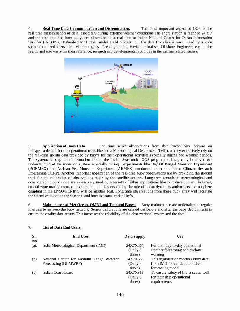
146
4. Real Time Data Communication and Dissemination. The most important aspect of OOS is the real time dissemination of data, especially during extreme weather conditions.The shore station is manned 24 x 7 and the data obtained from buoys are disseminated in real time to Indian National Center for Ocean Information Services (INCOIS), Hyderabad for further analysis and processing. The data from buoys are utilized by a wide spectrum of end users like; Meteorologists, Oceanographers, Environmentalists, Offshore Engineers, etc. in the region and elsewhere for their reference, research and developmental activities in the marine related studies. 5. Application of Buoy Data. The time series observations from data buoys have become an indispensable tool for the operational users like India Meteorological Department (IMD), as they extensively rely on the real-time in-situ data provided by buoys for their operational activities especially during bad weather periods. The systematic long-term information around the Indian Seas under OOS programme has greatly improved our understanding of the monsoon system especially during experiments like Bay Of Bengal Monsoon Experiment (BOBMEX) and Arabian Sea Monsoon Experiment (ARMEX) conducted under the Indian Climate Research Programme (ICRP). Another important application of the real-time buoy observations are by providing the ground truth for the calibration of observations made by the satellite sensors. Long-term records of meteorological and oceanographic conditions are extensively used by a variety of other applications like port development, fisheries, coastal zone management, oil exploration, etc. Understanding the role of ocean dynamics and/or ocean-atmosphere coupling in the ENSO/ELNINO will be another goal. Long time observations from these buoy array will facilitate the scientists to define the seasonal and intra-seasonal variability’s. 6. Maintenance of Met Ocean, OMNI and Tsunami Buoys. Buoy maintenance are undertaken at regular intervals to up keep the buoy network. Sensor calibrations are carried out before and after the buoy deployments to ensure the quality data return. This increases the reliability of the observational system and the data. 7. List of Data End Users.
Sl. No
End User Data Supply Use
(a). India Meteorological Department (IMD) 24X7X365 (Daily 8 times)
For their day-to-day operational weather forecasting and cyclone warning
(b) National Center for Medium Range Weather Forecasting (NCMWRF)
24X7X365 (Daily 8 times)
This organisation receives buoy data from IMD for validation of their forecasting model
(c) Indian Coast Guard 24X7X365 (Daily 8 times)
To ensure safety of life at sea as well for their ship operational requirements.
147
(d) Indian National Centre for Ocean Information Services (INCOIS)
24X7X365 (Daily 8 times)
To support Potential Fishing Zone notification and validation of ocean state forecasting model
(e) World Meteorological Organisation (WMO) 24X7X365 (Daily 8 times)
Data is given in GTS format to IMD to disseminate to WMO for their activates such as understanding global climate and forecast.
(f) National Hydrographic Office (NHO) Monthly For issuing Navigational Warnings (g) Ports (Ennore, Tuticorin, Mangalore & Goa) Monthly For vessel traffic management and
port development activities. (h) Indian Space Research Organisation (ISRO),
Space Application Centre (SAC) & Vikram Sarabhai Space Centre (VSSC)
On Request For satellite Data Validation and allied research uses
(j) Indian Climate Research Programme (ICRP),IISC Bangalore, Department of Science & Technology
On Request Climate research
(k) Naval Physical Oceanographic Laboratory (NPOL)
On Request For various research activities
(l) Naval Physical Oceanographic Laboratory (NPOL)
On Request For various research activities
(m) Oil and Natural Gas Corporation Limited Specific project
requirements
Environmental monitoring for Oil exploration activities
(n) Universities (Andhra, Kerala Agricultural University, Cochin & Mangalore)
On Request For research and academic purposes
(p) Central Marine Fisheries Research Institute (CMFRI)
On Request For various research activities
148
8. Buoy Locations. ARABIAN SEA MET OCEAN BUOY LOCATIONS
Buoy Id
Latitude (N)
Longitude (E)
AD01 19°00'.33N 67°00'.07E
SW02 17°21'.10N 70°42'.13E
AD02 14°59‘.93N 68°59‘.98E
AD03 12°01'.35N 68°58'.32E
AD05 10°29'.60N 72°16'.22E
AD04 08°30'.05N 73°00'.43E
ARABIAN SEA TSUNAMI BUOY LOCATIONSTB12 21°24'.00N 64°06'.00E
STB02* 20°48'.00N 65°20'.40E
BAY OF BENGAL MET OCEAN BUOY LOCATIONS BD01 18°10'.02N 89°40'.00E
BD02 17°57'.85N 89°43'.93E
BD03 16°21'.20N 88°00'.03E
BD04 13°29'.52N 83°58'.07E
RP01 11°35'.55N 92°36'.22E
BD06 10°00'.70N 88°30'.15E
BD05 10°30'.00N 94°00'.00E
BD14 06°11'.25N 85°52'.10E
BAY OF BENGAL TSUNAMI BUOY LOCATIONSTB05 11°00'.00N 89°30'.00E
TB06 15°00'.00N 90°00'.00E
TB08 12°30'.00N 85°30'.00E
STB01* 06°15'.00N 88°48'.00E
STB03* 03°48'.00N 91°42'.00E
*Deployed and maintained by INCOIS – Hyderabad.
Note: The present positions of the buoys may be obtained from the latest edition of Indian Notices to Mariners. 9. Use of Buoys to Fishermen. Buoys are fisherman’s friend at sea capable of identifying cyclones, storm surges and Tsunamis which causes loss of life, devastation and misery. The data observed by these buoys help to provide weather forecast and warnings in advance. In addition to the weather forecast, fish potential zones can also be identified with the help of data buoys, enabling the fishermen to locate the fishing zone. The ability to predict future climatic events and to estimate the degree to which they will disturb the ocean and its resources can potentially help fishermen to plan their operations in advance. Several nations have also on numerous occasions successfully used the wind and ocean current data from buoys to locate the missing boats.
149
10. Advice to Fishermen. (a) Always keep watch for the buoys at sea. (b) They are visible on your radar system.
(c) Signaling beacon light buoys helps you to identify them during night.
(d) Always keep off your fishing operations from buoys to avoid entanglement of your net.
(e) Don’t tie your boats, damage or destroy any part of the buoy, since they provide valuable information for your life at sea.
(f) If your net gets entangled with the buoy mooring, do not damage or cut the buoy mooring to retrieve them.
(g) Since the buoy is under a great deal of tension, if lifted or pulled, will cause severe damage to you and your boat.
(h) If anyone found tampering the buoy will be punished severely.
(j) Whenever you see a buoy drifting or anyone attempting to damage the buoy, immediately informs that to your nearest Police Station or call on us in address given below: Group Head, Ocean Observation Systems, National Institute of Ocean Technology Velachery – Tambaram Road, Pallikaranai, Chennai India Pin – 600 100. Phone : 044-22462944 / 22460678 / 66783536 / 66783537 / +91-9445040408 Fax : 044-22460661 / 66783400 Email : [email protected]

150
Special Notice No.17: SIGNIFICANCE OF GOOD SEAMANSHIP AND SAFE NAVIGATIONAL WATCHKEEPING PRACTICES Source: Director General of Shipping (Govt. of India)
The Directorate General Shipping based on the past experience recognises the fact that the adverse weather conditions during the seasonal southwest monsoon period in Indian waters hampers the safety of navigation. In the light of these circumstances, the mariner is urged to adhere to the following guidelines while navigating in the approaches of Indian ports or along the coast of India especially during severe monsoon months. However such precautions or practices are recommended during any part of the year. 1. Masters urged to use latest updated, largest scale Indian published navigational charts.
2. Master shall ensure that vessel draws adequate draft and trim to achieve 100 percent propeller submergence. 3. Masters should ensure that anchors are kept in readiness for letting go in the event of any untoward situation to save his ship, crew, and cargo and protect marine environment. 4. Master shall ensure that main propulsion and steering system of his vessel are always kept in readiness for immediate maneuver. 5. It is responsibility of the master to obtain latest weather bulletin of the concerned area of navigation prior to entering into Indian waters as well as while awaiting a anchorage or at roadstead. 6. The contingency plan is one of the components of comprehensive voyage plan therefore to keep available at all times to combat any emergency situation during navigation. 7. The storm signal hoisted by Indian Port, Signal station (PSS) shall be taken into account while navigating in the approaches of the ports. 8. The vessel during navigation shall display lights and shapes and use appropriate sound signal during navigation as prescribed by Collision regulation 1972 or the special rules made by the port authorities. 9. The Master shall ensure that all Navigational watch keeping officers apply the provision of Collision regulation, 1972 or special rules made by the port to avoid risk of collision or close quarter situations.
10 The latest navigational warnings in force issued by the ports or coast radio stations or National Hydrographic Office, Dehradun as the case may be shall closely be monitored and taken into account ensuring safe navigation.
11. Nevertheless, the fundamentals of observing of good seamanship, navigational watch keeping, limitations encountered by the vessel and special circumstances if any, must be taken into consideration to enhance safe navigation.

151
Special Notice No. 18 INTERNATIONAL HYDROGRAPHIC ORGANIZATION Source: www.iho.int
1. The International Hydrographic Organization is an intergovernmental consultative and technical organization that was established in 1921 to support safety of navigation and protection of marine environment. 2. Historical Background. International cooperation in the field of hydrography began with a Conference held in Washington in 1899, followed by two others in Saint Petersburg, in 1908 and 1912. At the suggestion of the Hydrographers of Great Britain and France the first International Hydrographic Conference was convened in London from 24 June to 16 July 1919, attended by Hydrographers and other representatives of 24 nations, during which it was decided that a permanent body should be created. The resulting International Hydrographic Bureau began its activity in 1921 with nineteen Member States. At the invitation of H.S.H. Prince Albert I of Monaco, a noted marine scientist, the Bureau was provided with headquarters in the Principality of Monaco. The Organization has remained in Monaco ever since, thanks to the continuing and very generous support of the Prince's successors. 3. Convention on The International Hydrographic Organisation. An Intergovernmental Convention on the Organisation was drafted during the IXth I.H. Conference in 1967 and, after ratification by the required majority of Member Governments, came into force on 22 September 1970. From that date, the term International Hydrographic Bureau (IHB) refers only to the headquarters of the Organisation, with the organisation itself being referred to as the International Hydrographic Organisation (IHO).The Organization currently has a membership of eighty maritime States, with several others in the process of becoming Members. 4. Administration. The administration of the IHO is carried out by a committee of three elected Directors, who must be of different nationalities, all of whom are required to be “men of considerable sea experience and with great knowledge of practical hydrography”. One of the three is elected President of the Directing Committee. A small permanent staff of technical experts and clerical assistants aids the Directing Committee in its work. The Directing Committee, together with a small international staff of technical experts in hydrography and nautical cartography, makes up the International Hydrographic Bureau in Monaco. The IHB is the secretariat of the IHO, coordinating and promoting the IHO's programmes and providing advice and assistance to Member States and others. 5. The objectives of the Organization are to bring about:-
(a) The greatest possible uniformity in nautical charts and documents.
(b) The adoption of reliable and efficient methods of carrying out and exploiting hydrographic surveys.
(c) The development of the sciences in the field of hydrography and the techniques employed in descriptive oceanography.
6. IHO Areas of Activity. The principal activities undertaken by IHO are as appended below:-
(a) Standardization. IHO has consistently worked towards achieving maximum standardization of nautical products, services and survey practices. IHO publication M-4 is an example of an IHO standard that has resulted in the adoption of consistent colours, symbols, nomenclature and general presentation for charts produced by IHO Member Organization.

152
(b) The International (INT) Chart. The idea of a common, worldwide chart series (INT Charts) produced to a single set of agreed specifications was adopted in 1971. Under this arrangement, member nations wishing to print their own versions of another members INT charts, may do so by obtaining (by mutual agreement), copies of the necessary reproducible material and printing their own copies.
(c) Capacity Building and Technical Cooperation. The Organization assesses and assists in sustainable development and improvement of the States, to meet the objectives of the IHO and the Hydrography, Cartography and Maritime Safety obligations and recommendations described in UNCLOS, SOLAS V and other international instruments. In 2002 the International Hydrographic Organization created a new Committee called the Capacity Building Sub-Committee (CBSC). A Capacity Building Fund has been created to provide support for the main categories of capacity building activity i.e. technical assistance, training and education, financial assistance for participation in IHO events and start-up funding for hydrographic elements of projects, as identified in the IHO Capacity Building Strategy.
(d) Education and Training. Over twenty of IHO Member States offer more than thirty technical training programs in hydrography that conform to guidelines established by the IHO. In some instances these programs are offered free of charge while others provide scholarships to those attendees that demonstrate the need. In cooperation with the Fédération Internationale des Géomètres (FIG), and the International Cartographic Association (ICA), a comprehensive set of Standards of Competence for hydrographic surveyors and nautical cartographers have been drawn up, together with appropriate syllabi for the guidance of universities and teaching establishments throughout the world. An International Board supervises the application of these standards with a view to achieving internationally recognized qualifications in the hydrographic profession. The Board reviews the training syllabi of worldwide educational institutions, and awards international certificates of recognition to those courses which have achieved the required minimum standards of competence. Three important publications relating to education and training include:
(i) IHO Publication S-5: "Standards of Competence for Hydrographic Surveyors";
(ii) IHO Publication S-8: "Standards of Competence for Nautical Cartographers";
(iii) IHO Publication C-47: "Courses in Hydrography and Nautical Cartography
(e) External Stakeholder Liaison. The International Hydrographic Organization works with a wide spectrum of International Organizations, Industry Stakeholders and other important associated communities.
(f) Bathymetry and Ocean Mapping. The IHO contributes towards development of scientific knowledge of the ocean environment by coordinating the systematic collection and recording of ocean bathymetry on a World Series of Bathymetric Plotting Sheets. This global coverage of deep ocean data, is available to hydrographers, oceanographers, geoscientists and educational institutions. Much of the data contained on these plotting sheets have been digitised and are available from the IHO Data Centre for Digital Bathymetry (DCDB) which is located at the U.S. National Geophysical Data Center, Boulder, Colorado, USA. The bathymetric data are also used for the preparation of the General Bathymetric Chart of the Oceans (GEBCO), which comprises 18 separate map sheets, covering all oceanic areas. The GEBCO Series is produced jointly by the IHO and the Intergovernmental Oceanographic Commission (IOC) of UNESCO. The 5th Edition of the GEBCO was completed in 1982, and its digital equivalent, the GEBCO Digital Atlas (GDA) is available on CD-ROM.
153
7. The IHO also participates in several IOC sponsored regional International Bathymetric Chart projects, namely:-
(a) The International Bathymetric Chart of the Arctic Ocean (IBCAO);
(b) The International Bathymetric Chart of the Caribbean Sea and the Gulf of Mexico (IBCCA);
(c) The International Bathymetric Chart of the Central Eastern Atlantic Ocean (IBCEA);
(d) The International Bathymetric Chart of the Mediterranean and Black Seas (IBCM);
(e) The International Bathymetric Chart of the South Eastern Pacific (IBCSEP);
(f) The International Bathymetric Chart of the Southern Ocean (IBCSO);
(g) The International Bathymetric Chart of the Western Indian Ocean (IBCWIO);
(h) The International Bathymetric Chart of the Western Pacific Ocean (IBCWP);
8. IHO Publications. IHO produces numerous publications which are available from the IHO Web-site, or can be provided on CD-ROM. Printed copies of some periodical publications are also available. Most IHO publications are produced in English and French, however some of the more significant publications are also issued in Spanish.
9. International Hydrographic Conferences. The International Hydrographic Conference (IHC) is formed by the representatives of Member States and meets every five years to provide general guidance on the functioning and work of the organization, as well as taking decisions of technical and administrative nature. The official representative of each Member Government within the IHO is normally the national Hydrographer, or Director of Hydrography, who, together with their technical staff, meet at 5-yearly intervals in Monaco for an International Hydrographic Conference. The Conference reviews the progress achieved by the Organization through its committees, sub committees and working groups, and adopts the programmes to be pursued during the ensuing 5-year period. A Directing Committee of three senior hydrographers is elected to administer the work of the Organization during that time.
BUREAU HYDROGRAPHIC INTERNATIONAL 4 QUAI ANTONIE I er
B.P. 445 MC 98011 MONACO CEDEX
TELEPHONE: +377 93 10 81 00 TELEFAX: +377 93 10 81 40
TELEX: 479164 MC-INHORG e-mail (INTERNET): [email protected]
http://www.iho.shom.fr/ INTERNATIONAL HYDROGRAPHIC BUREAU
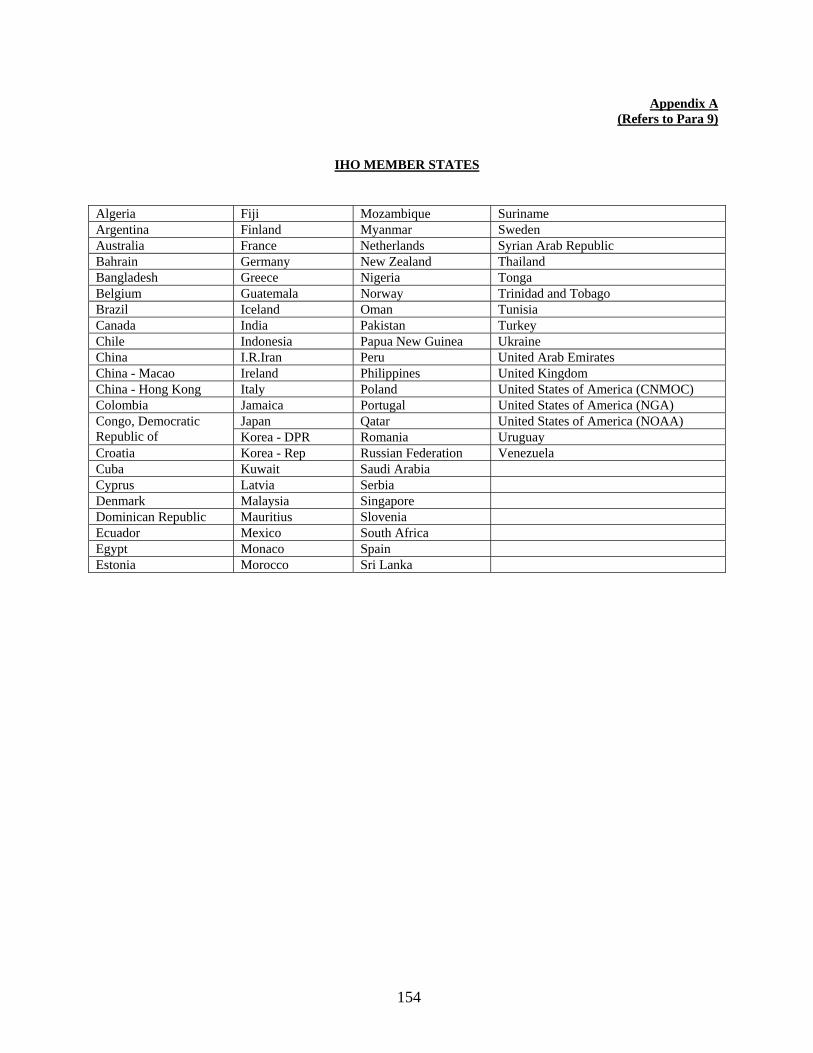
154
Appendix A (Refers to Para 9)
IHO MEMBER STATES
Algeria Fiji Mozambique Suriname Argentina Finland Myanmar Sweden Australia France Netherlands Syrian Arab Republic Bahrain Germany New Zealand Thailand Bangladesh Greece Nigeria Tonga Belgium Guatemala Norway Trinidad and Tobago Brazil Iceland Oman Tunisia Canada India Pakistan Turkey Chile Indonesia Papua New Guinea Ukraine China I.R.Iran Peru United Arab Emirates China - Macao Ireland Philippines United Kingdom China - Hong Kong Italy Poland United States of America (CNMOC) Colombia Jamaica Portugal United States of America (NGA) Congo, Democratic Republic of
Japan Qatar United States of America (NOAA) Korea - DPR Romania Uruguay
Croatia Korea - Rep Russian Federation Venezuela Cuba Kuwait Saudi Arabia Cyprus Latvia Serbia Denmark Malaysia Singapore Dominican Republic Mauritius Slovenia Ecuador Mexico South Africa Egypt Monaco Spain Estonia Morocco Sri Lanka

155
Special Notice No. 19: INFORMATION ABOUT RADAR BEACONS Source: Director General of Lighthouses and Lightships 1. Radar beacons are being installed on the Indian Coast. These Racons are located on the conspicuous objects like light houses, light floats etc. They operate in ‘I’ band marine radar (9300 to 9500 Mhz) and provide information on bearing as well as range by means of special coded signals displayed on the ships radar screen. A typical radar display with racons is shown in the accompanying diagram. Range is measured from the centre of the PPI to the inner most point of the special coded signal received from the racon after applying a standard negative correction of 75 metres (246 feet), in order to take care of the delay between reception and transmission.
2. Racons have been installed at the following places and their details are as follows:- Sr. No.
Station name Sector Service:: Continuous
Code Position
1. Jakhau 360° Yes M 23°14. 40’N, 68°36.30’E 2. Mandvi 360° Yes G 22°49. 80’N, 69°20.90’E 3. Navlakhi 360° Yes B 22°58 .00’N, 70°27.00’E 4. Pirotan 360° Yes K 22°37. 12’N, 69°16.22’E 5. Bural 360° Yes D 22°32. 67’N, 69°16.22’E 6. Okha 360° Yes O 22°28. 58’N, 69°04.20’E 7. Kachhigadh 360° Yes K 22°19 .82’N, 68°57.53’E 8 Dwarka 360° Yes G 22°14. 23’N, 68°57.53’E 9. Porbander 360° Yes D 21°37. 33’N, 69° 37. 7’E 10. Veraval 360° Yes K 20°54. 60’N, 70°21.20’E 11. Sawaibet 360° Yes M 20°54. 12’N, 71° 31. 6’E 12. Gopnath 360° Yes G 21°12. 20’N, 72°06.60’E 14. Piram 360° Yes B 21° 35. 54’N, 72° 21.2’E 15. Hazira 360° Yes K 21°05. 31’N, 72°38.36’E 16. Umargaon 360° Yes M 20°11. 07’N, 72°45.00’E 17 Navinal 360° Yes C 22°44. 04’N, 69°42.80’E 18. Diu Head 360° Yes D 20°41. 50’N, 70°49.70’E 19. Alang 360° Yes C 21°24. 20’N, 72°11.10’E 20 Luhara Point 360° Yes D 21°39. 50’N, 72°32.90’E

156
21. Ratnagiri 360° Yes G 16°59. 20’N, 73°46.40’E 22. Aguada 360° Yes O 15°29. 50’N, 73°46.40’E 23. Vengrula Rock 360° Yes D 15°53. 40’N, 73°27.70’E 24. Korlai Fort 360° Yes O 18°32. 30’N, 72°54.50’E 25. Mount Dilli 360° Yes K 12°00. 37’N, 75°12’E 26. Beypore 360° Yes G 11°09. 43’N,73°48 .39’E 27. Androth Island 360° Yes D 10°48. 8’N, 73°42.1’E 28. Minicoy 360° Yes G 8°15. 98’N, 73°01.57’E 29. Suhelepar 360° Yes O 10°02. 4’N, 72°17. 0’E 30 Kavaratti 360° Yes K 10°33. 7’N, 72°38. 9’E 31. Vypin (Cochin) 360° Yes K 9°59. 82’N, 76°13. 35’E 32. Kiltan 360° Yes O 11°29. 8’N, 73°00. 0’E 33. Agathi 360° Yes B 10°52. 5’N, 72°12. 3’E 34. Kadmath 360° Yes G 11°15. 4’N, 72°47. 4’E 35. Pandian Tivu 360° Yes O 08°47. 1’N, 78°11. 9’E 36. Muttum 360° Yes M 8°07. 4’N, 77°19. 1’E 37. Nagapatnam 360° Yes G 10°45. 9’N, 79°51 .1’E 38. Pondicherry 360° Yes D 11°59. 4’N, 79°49 .9’E 39. Madras 360° Yes K 13° 02.34’N,80°16 .85’E 40. Pulicat 360° Yes B 13° 25 .12’N, 80° 19.2’E 41. Kanya Kumari 360° Yes C 8° 04 .8’N, 77° 32. 8’E 42. Mannpad 360° Yes G 8° 22 .3’N, 78° 03. 9’E 43. Portonovo 360° Yes B 11° 30 .2’N, 79° 46. 2’E 44. Ramayapatnam 360° Yes K 15° 02 .7’N, 80° 03. 0’E 45. Vakalpudi 360° Yes G 17° 00 .8’N, 82° 17. 1’E 46. Paradip 360° Yes K 20° 15 .3’N, 86° 39. 5’E 47 Gopalpur 360° Yes G 19° 15 .3’N, 84° 54. 5’E 48. Dolphin Noise 360° Yes O 17° 40 .5’N, 83° 17. 7’E 49. Daripur 360° Yes G 21° 47 .4’N, 87° 51. 9’E 50. Oyster Rock 360° Yes D 14° 49 .2’N, 74° 03. 4’E 51. Suratkal 360° Yes C 13° 00 .2’N, 74° 47. 4’E 52. Vililinjam 360° Yes O 8° 22 .9’N, 76° 58. 8’E 53. Krishnapatinam 360° Yes C 14° 15 .2’N, 80° 07. 7’E 54. Antervedi 360° Yes B 16° 19 .0’N, 81° 43. 6’E 55. Prongs reef 360° Yes G 18° 52 .7’N, 72° 48. 0’E 56. East Island 360° Yes D 13° 37 .8’N, 93° 03. 5’E 57. North Point 360° Yes K 11° 43 .3’N, 92° 49. 9’E 58. Keating Point 360° Yes O 9° 15 .4’N, 92° 46. 3’E 59 Indira Point 360° Yes G 6° 45 .0’N, 93° 49. 75’E 60 Tapti 360° Yes C 20° 32 .44’N, 071° .29’E 61 WIN(North
Field) 360° Yes B 19° 37.84’N 71°17.77’E
62 SHQ(South Field)
360° Yes D 19° 17.33’N,071° .54’E
63 NLM (Heera Field)
360° Yes G 18° 48.41’E, 72° 8.04’E
64 BLQ-11 (Bassein field)
360° Yes C 19°07.39’N, 72° .44’E
65 Chowra Island 360° Yes B 08°27.40’N, 93° 2.90’E

157
Special Notice No. 20: DEVELOPMENT OF OFFSHORE OIL AND GAS FIELDS Source: Offshore Defence Advisory Group Seismic Surveys. 1. Seismic surveys for offshore oil and mineral resource explorations are conducted in and around Indian waters. Details of these surveys are generally broadcast to mariners as a Radio Navigational Warning or by Notices to Mariners. It is seldom practicable to publish details of the areas of operation except in general terms and vessels carrying out seismic surveys may, therefore, be encountered without prior notice. Seismic survey vessels operate either alone or in company and may tow a sensing device in the form of buoyant cable streamed one to two nautical miles astern. The sensing device may be on the surface or at depths down to approximately 12 metres (40 feet) and an orange buoy usually attached to the end of cable, displays quick flashing light and carries a radar reflector. 2. In the process of the survey, repeated shock waves are created by using at any level from the bottom to the surface, explosive charges, compressed air, mechanical liberators or by electrical means. Occasionally, explosive charges of up to 2000 lbs are used. The seismic surveys vessels will usually be making way through the water but sometimes stop for extended periods. 3. Seismic survey vessels which are unable to manoeuvre are required to carry the lights and signals, described in Rule 27 of International Regulations for Preventing Collisions at Sea, 1972 and should be given a wide berth (2 to 2½ miles). 4. If charges are being fired by radio or electrically triggered detonators, survey vessels may suspend radio and radar transmission to avoid accidental firings. Vessels being called by light are, therefore, to answer by the same means and not by radio. 5. Charges may be contained in a variety of cylinders, tubes or bags which may be marked as "Dangerous". No attempt to recover such items should be made and if any is inadvertently taken aboard in trawlers, etc., should be jettisoned immediately. Oil Rigs and Production platforms. 6. There are two types of drilling rigs in use at present in Indian Offshore fields:-
(a) Jack-up Rigs: - These are propelled/towed in positions where their steel legs are lowered to the seabed; the drilling platform is then jacked-up clear of the water. They are generally used in depths upto 100 metres. (b) Dynamic Positioning Drill ships: - These are built with a tall drilling rig amidship and usually with a helicopter deck near the stern. A typical drill ship has a displacement of 14,000 tons, a length of 135m and a maximum speed of 14 Knots. For drilling in depths of less than 200 metres, 8-point anchoring system is used. When drilling in deep water, their position is maintained by dynamic positioning equipment which enables these drill ships to keep on stations above the borehole. A feature of the drill ships with automated station- keeping facilities is their ability to manoeuvre accurately, with the aid of thrusters fitted with controlled pitch propellers. These are used in depths above 200 metres.
Wellheads. 7. In the course of exploratory work, numerous wells are drilled to find the extent of the field. Wells which will not be required again are sealed with cement plug below the seabed and abandoned. 8. Other wells, known are suspended wells, which may be required at a later date have their wellheads capped and left with a pipe and other equipment projecting from the seabed. Such wellheads are sometimes marked by buoys to assist recovery and to warn the mariners that they are a hazard to navigation or fishing.

158
Production Platforms/Water Injection/Process Platforms. 9. These are massive structure carrying drilling and production equipment, oil and gas separation and treating plants, pumpline stations, electricity generators, cranes and helicopter landing deck. They are marked by lights, fog signals, and on some platforms flares burn at times. Production Platforms are charted. Platforms stand singly or in groups, linked to each other by pipelines and bridges. Process platforms are manned round the clock and have residential accommodation. A trunk pipeline connects them to the shore/storage tanker/tanker loading buoy or a floating terminal. Subsea Structure / Wellheads. 10. These structures are basically Wellheads, pipeline, etc. and manifolds installed at the seabed in deepwater area/shallow water area and need to be protected from any possible damages due to anchoring and sinking of vessels. Loading and Unloading System. 11. A variety of moorings, generally referred to a Single Point Mooring (SPM) have been developed to enable large vessels to moor by their bows to either load or unload their cargoes. There are at present Single Buoy Moorings (SBM) moored in Bombay oilfield and at Vadinar offshore oil terminal to facilitate oil tankers to be moored for transportation of crude. Safety Zones. 12. Under International law, a coastal state may construct and maintain on the continental shelf installations and other devices necessary for the exploration of its natural resources, establish Safety Zones around such installations and devices and take within these zones measures necessary for their protection. 13. Safety zones may extend to a distance of 500 metres around installations and other devices, measured from each point of their outer edges. Ships of all nationalities are required to respect these safety zones. 14. Several coastal states have made provisions in their National Law to cover the establishment of safety zones and have made infringement of the declared zones a criminal offence. Since the type of offshore installation subject to safety zone differ from State to State, mariners are advised always to assume the existence of a safety zone unless they have information to the contrary. Installation and devices include fixed production platforms, mobile exploration rigs, tanker loading moorings and seabed installations including submerged wellheads. The Government of India has established 500-metre safety zones around each installation in the oil field development areas. Mariners should not enter these safety zones 15. Some coastal states have declared Prohibition on entry into, or on fishing and anchoring within, areas extending beyond 500 metres from the installations. Publication of the details of such wider areas is solely for the safety and convenience of shipping and implies no recognition of the international validity of such restrictions. See also “The Mariners Handbook" (BA NP 100), chapter 1 section 1. Warning to Mariners. 16. Fixed platforms, wellheads, SBMs and pipelines are normally charted. The mobile rigs move from site to site at irregular intervals and details of their movements and positions are promulgated to shipping by means of NAVAREA VIII warnings. 17. It is essential that all vessels keep well clear of these structures; underwater and surface hazards to navigation exist in their vicinity and in any case consequences of damage of collision could be disastrous. 18. Within certain oilfields which are being developed or are already producing oil and gas the limits of which are charted, there are likely to be construction and maintenance vessels including submarine crafts, divers and obstruction, possibly marked by buoys. Supply vessels and in some cases, tankers, frequently manoeuvre within these fields, Mariners are strongly advised to keep outside such areas.

159
19. Vessels encountering uncharted oil platforms/ structures are to report the matter immediately at following addresses: - (a) Chief Hydrographer to the Government of India P. O. Box No. 75
107-A Rajpur Road Dehradun - India - 248 001
Tel: - 91-135-2747365, 2747360 Fax: - 91-135-2748373 Email: [email protected] [email protected] (b) Flag Officer: - Offshore Defence Advisory Group; 15th Floor, F-Wing Maker Towers
Cuffe Parade Mumbai: - 400 005
Tel: - 91-22 22181424 Fax: - 91-22 22151906 Light and Fog Signals. 20. Offshore structure operating in Indian waters will carry the following internationally agreed marking:-
(a) White lights on the horizontal extremities of the structure flashing in uniform Morse 'U' every 15 secs., range 10 miles.
(b) A fixed red light on the highest point of the structure. (c) Illuminated identification. (d) A signal sounding Morse 'U' every 30secs, when the visibility is less than 2 nautical miles.

160
Special Notice No. 21: TRAFFIC SEPARATION SCHEMES - SHIPS ROUTEING. Source: Director General of Shipping (Govt. of India), www.imo.org
1. Ships' routeing systems contribute to safety of life at sea, safety and efficiency of navigation and/or protection of the marine environment. Ships' routeing systems are recommended for use by, and may be made mandatory for, all ships, certain categories of ships or ships carrying certain cargoes, when adopted and implemented in accordance with the guidelines and criteria developed by the Organization. 2. Traffic separation schemes and other ship routeing systems have now been established in most of the major congested; shipping areas of the world and the number of collisions and groundings have often been dramatically reduced.
3. In 1961, the Institutes of Navigation of the Federal Republic of Germany, France and the United Kingdom carried out a study of measures for separating traffic in areas where statistics indicated increased risk of collision. The first Traffic Separation Scheme was implemented in the Dover Strait in 1967. Since then a larger number of similar routeing schemes have been established throughout the world. The details are shown on the charts and referred to in Sailing Directions. For further information about ships' routeing, see ’The Mariner's Handbook '' (BA NP 100) Chapter 4, Section 4. 4. The International Maritime Organisation (IMO) is the only body responsible for establishing and recommending measures on an international level concerning ships routeing. Where in schemes lie wholly within territorial water, decisions concerning routeing rest with the national government but such schemes may also be submitted for IMO's approval and adoption. The details of schemes adopted by IMO are set out in the IMO Publication "Ships' Routeing", 2010 edition. Member states of IMO usually take legislative action to ensure that their nationally registered ships adhere to the measures and routes adopted by the Organisation. In some schemes, special provisions are included governing their use by all ships or by specified classes of ships. On the charts, relevant information are given or there are recommendations to chart users to consult Sailing Directions for details.

161
5. The schemes approved by IMO and the routes established by coastal states or other competent national authorities concerned with the safety of navigation will be inserted on navigational charts. On the charts, the IMO-adopted schemes are not differentiated from other routeing schemes; however, all charts showing traffic separation schemes will carry a reference to this Notice. While vessels using the traffic lanes in schemes adopted by IMO must, in particular, comply with Rule 10 of International Regulations for Preventing Collisions at Sea, 1972, they are not thereby given any right of way over crossing vessels. The other steering and sailing Rules still apply in all respects, particularly if the risk of collision is involved. 6. Where two or more Governments have a common interest in a particular area, they should formulate joint proposals for the delineation and use of a routeing system therein on the basis of an agreement between them. Upon receipt of such proposal and before proceeding with consideration of it for adoption, the Organization shall ensure details of the proposal are disseminated to the Governments which have a common interest in the area, including countries in the vicinity of the proposed ships' routeing system. Contracting Governments shall adhere to the measures adopted by IMO concerning ships' routeing. They shall promulgate all information necessary for the safe and effective use of adopted ships' routeing systems. A Government or Governments concerned may monitor traffic in those systems. Contracting Governments shall do everything in their power to secure the appropriate use of ships' routeing systems adopted by the Organization. Mandatory ships' routeing systems shall be reviewed by the Contracting Government or Governments concerned in accordance with the guidelines and criteria developed by the Organization. 7. A ship shall use a mandatory ships' routeing system adopted by the Organization as required for its category or cargo carried and in accordance with the relevant provisions in force unless there are compelling reasons not to use a particular ships' routeing system. Any such reason shall be recorded in the ships' log.
8. Governments intending to establish a new routeing system, or amend an existing one, must submit proposed routeing measures to IMO's Sub-Committee on Safety of Navigation (NAV), which will then evaluate the proposal and make a recommendation regarding its adoption. The recommendation is then passed to the MSC for adoption.
9. As well as traffic separation schemes, other routeing measures adopted by IMO to improve safety at sea include two-way routes, recommended tracks, deep water routes (for the benefit primarily of ships whose ability to manoeuvre is constrained by their draught), precautionary areas (where ships must navigate with particular caution), and areas to be avoided (for reasons of exceptional danger or especially sensitive ecological and environmental factors).
10. Elements Used in Traffic Routeing Systems Include:
(a) Traffic separation scheme: a routeing measure aimed at the separation of opposing streams of traffic by appropriate means and by the establishment of traffic lanes.
(b) Traffic lane: an area within defined limits in which one-way traffic is established. Natural obstacles, including those forming separation zones, may constitute a boundary.
(c) Separation zone or line: a zone or line separating traffic lanes in which ships are proceeding in opposite or nearly opposite directions; or separating a traffic lane from the adjacent sea area; or separating traffic lanes designated for particular classes of ship proceeding in the same direction.
(d) Roundabout: a separation point or circular separation zone and a circular traffic lane within defined limits.
(e) Inshore traffic zone: a designated area between the landward boundary of a traffic separation scheme and the adjacent coast.
(f) Recommended route: a route of undefined width, for the convenience of ships in transit, which is often marked by centerline buoys.

162
(g) Deep-water route: a route within defined limits which has been accurately surveyed for clearance of sea bottom and submerged articles.
(h) Precautionary area: an area within defined limits where ships must navigate with particular caution and within which the direction of flow of traffic may be recommended.
(j) Area to be avoided: an area within defined limits in which either navigation is particularly hazardous or it is exceptionally important to avoid casualties and which should be avoided by all ships, or by certain classes of ships.
11. The annexed list contains details of the Traffic Separation Schemes at present included in the chart series or in the process of being inserted for the North Indian Ocean area from South Africa Coast to Singapore, including the Red Sea and the Persian Gulf. Several facts about each scheme are given:
(a) The geographical positions quoted are approximate and, with the place names, are given merely to indicate the general location of the scheme and to facilitate its identification on the charts. If any extensive area is involved, the geographical co-ordinates of the extreme ends of the separation zones or lines are given. (b) The schemes which have been adopted by IMO are marked* in the margin. For other schemes, the originating authority is given. Any change to the schemes during the year will be announced through Notices to Mariners. (c) In each case, only the principal charts, on which the details of the scheme are shown, are quoted. Separate latticed versions are not listed. (d) In some cases, the volumes of Admiralty Sailing Directions which contains details of the scheme are quoted under the heading "Remarks".
List of Traffic Separation Schemes Shown on Indian/Admiralty Charts. *1. In the Gulf of Suez.
Charts: B.A. 2133, 333, 2373, 2374, 2375,159 (The Mariners Roueting Guide - Chart 5501 is recommended as an additional reference). 2. In the Approaches to Yanbu Charts: B.A. 326, 327, 328, 158 The Royal Commission for Jubail and Yanbu, Kingdom of Saudi Arabia. *3. In the Strait of Tiran 801, 2375, 12, 159
*4. In Bab-el-Mandeb Charts: 8010, B.A. 452, 1925, 3661, 143, 6, 157
*5. West and South of Hanish al Kubra Charts: B.A 453, 1925, 143, 6, 157
*6. East of Jabal Zuqar Island Charts: B.A 453, 1925, 143, 6, 157
*7. Off Ra's al Hadd,
Charts: B.A. 38, 2851, 707, 2858
*8. Off Ra’s al Kûh BA Charts: 3171, 3520, 2888, 2851, 2837, 2858
163
*9. In the Strait of Hormuz Charts: 8005, 8004, 289. B.A. 2851. *10. Tonb-Forur(Jazireh-ye Tonb-e Bozorg to Jazireh-ye Forur)
Charts: 8004, 289, B.A.2887. *11 Off Mînâ’al Ahmadî Charts: B.A. 1223, 3773, 2882, 2884, 2847, 2858 *12. Between Zaqqum and Umm Shaif Oilfields. Charts: B.A. 2443, 2444, 3178, 3179, 2886, 2887, 2889, 2837, 2858 *13. In the Approaches to Ra's Tanura Charts: B.A. 3776, 3812, 3777, 3788, 3790, 2882, 2883, 2886, 2837, 2847, 2858
Amended width of Arrival Channel not yet IMO adopted.
*14. In the Approaches to Ra's Ju'aymah (Persian Gulf) Charts: B.A. 3776, 3777, 3788, 2882, 2883, 2886, 2837, 2847, 2858 Remarks: See Admiralty Sailing Directions, N.P.63. *15. Between Zuluf and Marjan Oilfields Charts: B.A. 3774, 2882, 2884, 2847, 2858 16. Off Mumbai Charts: 211, 255(INT 7334), 2016(INT 7336) Director General, Shipping. Mandatory for all Indian and Foreign flag ships
India (Details available in Indian Notices to Mariners/381(14/08) and 443(16/08)). *17. Off Dondra Head (Sri Lanka). Charts: 226, 264, 32, and 23. 18. Port of Singapore — Traffic Systems – Sinki Fairway Charts: B.A. 4031, 4032, 4034, 4035, 4040, 3833 Maritime and Port Authority of Singapore Remarks: See Admiralty Sailing Directions, N.P.44. 19. Port of Singapore — Traffic Systems – Southern Fairway
Charts: B.A. 3833, 4035, 4036, 4037, 4040, 4041 Maritime and Port Authority of Singapore Remarks: See Admiralty Sailing Directions, N.P.44.
*20. At one Fathom Bank (Permatang Sedepa). Charts: B.A. 2139, 3940, 3945, 3946, 1353, 1358
Remarks: See Admiralty Sailing Directions, N.P.44. *21. Port Klang(Pelabuhan Klang) to Port Dickson
Charts: B.A. 1140, 2139, 3940, 3946, 1358 Remarks: See Admiralty Sailing Directions, N.P.44.
*22. Port Dickson to Tanjung Keling
Charts: B.A. 3946, 3947, 1358 Remarks: See Admiralty Sailing Directions, N.P.44.
*23. Melaka to Iyu Kecil
Charts: B.A. 3833, 2403, 3946, 3947, 1358 Remarks: See Admiralty Sailing Directions, N.P.44.

164
*24. In the Singapore’s Strait, (Main Strait) Charts: B.A. 4030, 4031, 4036, 4038, 4039, 4040, 4041, 3833, 5502, 2403, 3947, 1358
Remarks: See Admiralty Sailing Directions, N.P.44. *25. In the Singapore Strait(off St John’s Island(Pulau Sakijang Bendera)
Charts: B.A. 4040, 4041, 3833, 5502, 2403, 1358 Remarks: See Admiralty Sailing Directions, N.P.44.
*26. In the Singapore Strait(off Changi and Pulau Batam) Charts: B.A 4037, 4041, 4042, 3831, 3833, 5502, 2403 Remarks: See Admiralty Sailing Directions, N.P.44.
*27. At Horsburgh Lighthouse Area Charts: B.A. 4042, 3831, 2403, 1311, 3543, 5502, 1312
Remarks: See Admiralty Sailing Directions, N.P.44. * Details available in www.imo.org

165
Special Notice No.22: IALA MARITIME BUOYAGE SYSTEM Source: www.iala-aism.org
1. The severest test of buoyage system occurs when the mariner is confronted unexpectedly at night or in low visibility by the lights marking an uncharted danger, such as a recent wreck; immediately, he must decide which way to go. 2. The fact that the existing systems of buoyage are not always sufficiently understood was illustrated by a disaster in the Dover Strait in 1971. Although marked under the existing system, the wreckage of the Texco Caribbean was struck by the Brandenburg, which sank. A few weeks later the wreckage, despite being marked by a wreck-marking vessel and many buoys, was struck by the Niki, which also sank. On sighting a navigational mark, every mariner's reaction should be instinctive, positive and correct. In 1976, there were more than 30 different systems in use world-wide. Many of these systems have rules which conflict with one another. This has resulted in a situation which is particularly confusing at night when a mariner may be unexpectedly confronted by the light, the meaning of which is not clear. Such confusions can be unexpectedly dangerous when the light is marking a new and as yet uncharted danger. This may leave the mariner in doubt as to his proper course of action leading to make a wrong and perhaps disastrous decision. Over the years, many attempts have been made to solve these difficulties of opinion regarding various systems of buoyage but without success. The International Technical Committee of the International Association of Lighthouse Authorities (IALA) examined the problems of Uniform Maritime Buoyage System and promulgated two sets of Rules namely Region 'A' the Combined Cardinal and Lateral System (Red to Port) and Region 'B' Lateral System only (Red to Starboard). At the IALA conference convened at Tokyo in 1980, it was agreed to harmonise Systems 'A' and 'B' into a single IALA Maritime Buoyage System. Subsequently an agreement on the IALA Maritime Buoyage System came into force in April, 1982 when 28 Maritime countries of Region 'A', including India, have signed the agreement. 3. The Rules for Region 'A' have been agreed to by the International Maritime Organisation (IMO). They are particularly suitable for use in Europe, Africa, India, Australia and some Asian waters. This system is being utilised in India in the Approaches to Kandla, Gulf of Kachchh to mark the Deep water Route leading to Salaya Oil Terminal, Port Okha, Port of New Mangalore, Chennai Harbour, Kakinada Harbour, Visakhapatnam Harbour , Mormugao Port, Hugli etc. 4. Within both regions, use may be made of the full range of cardinal and other marks established for Region 'A'. Some minor features, appropriate in both regions, will be added to the existing system, the most significant being the provision of a modified lateral mark for indicating the preferred route where a channel divides. These changes and additions are unlikely to give rise significant alteration in the areas where IALA Buoyage system has already been implemented. 5 In the IALA System the regional (of the systems A and B) principle of painting of the lateral signs was maintained. The countries that accepted the red colour for the left hand lateral signs have been included in the region A. The countries that use the green colour for the left hand lateral signs were included in the region B. In both the regions, the fairway direction is the one leading from the sea (when a different manner is used than an adequate notice is provided). Following the division into the IALA System regions, marine maps contain respective notice, i.e. the "IALA System Region A" or the "IALA System Region B". The IALA System has five types of signs that are used in various associations. The signs have specific identification elements that make them easily recognizable to the sailors. The lateral signs in the Regions A and B are different, but the other four signs are common for these both regions. The lateral buoys and marks are placed according to the direction accepted for marking of the right and left side of the fairway. In the Region A, during the day and night, the green colour is used to mark the right side of the fairway, and the red colour - to mark the left side.

166
6. Description of Lateral Marks used in Region A.
Port Hand Marks Colour :Red Shape (Buoys) :Cylindrical (can) pillar or spar Topmark (if any) :Single red cylinder (can) Light (when fitted) Colour :Red Rhythm :Any, other than that described in para 8 below
Starboard Hand Marks Colour :Green Shape (Buoys) :Conical, pillar or spar Topmark (if any) :Single green cone, point upward Light (when fitted) Colour :Green Rhythm :Any, other than that described in para 8 below
In the Region B the colours are reversed, ie the red colour is used for the right side, and the green colour - for the left side.

167
7. Description of Lateral Marks Used in Region B.
Port Hand Marks Colour :Green Shape (Buoys) :Cylindrical (can) pillar or spar Topmark (if any) :Single green cylinder (can) Light (when fitted) Colour :Green Rhythm :Any, other than that described in para 9 below
Starboard Hand Marks Colour :Red Shape (Buoys) :Conical, pillar or spar Topmark (if any) :Single red cone, point upward Light (when fitted) Colour :Red Rhythm :Any, other than that described in para 9 below
When the path is divided on a fairway, then the direction of the main path is shown with a modified lateral buoy in order to indicate the direction of this main path.
8. Modified Lateral Buoys and Marks for the Region A.
At the point where the channel divides, when proceeding in the ''Conventional Direction of Buoyage'', a preferred channel may be indicated by a modified Port or Starboard lateral mark as follows:
Preferred Channel to Starboard:
Colour :Red with one broad green horizontal band Shape (Buoys) :Cylindrical (can), pillar or spar Topmark (if any) :Single red cylinder (can) Light (when fitted) Colour :Red Rhythm :Composite group flashing (2+1)
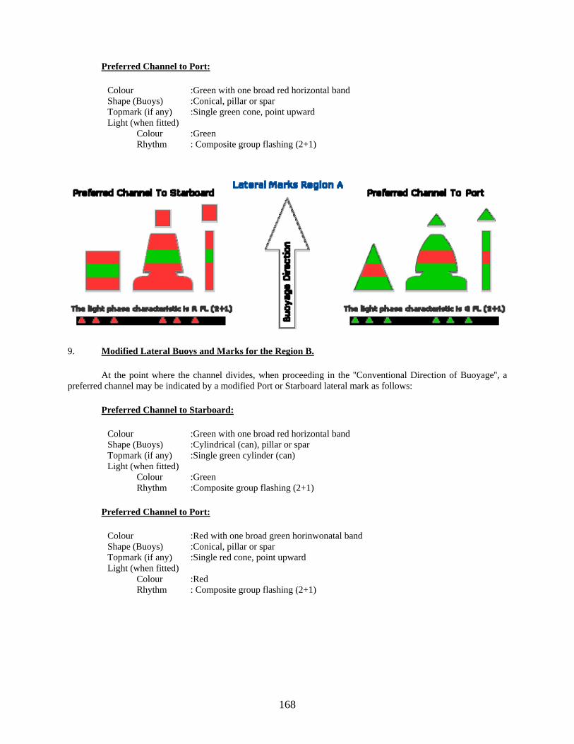
168
Preferred Channel to Port:
Colour :Green with one broad red horizontal band Shape (Buoys) :Conical, pillar or spar Topmark (if any) :Single green cone, point upward Light (when fitted) Colour :Green Rhythm : Composite group flashing (2+1)
9. Modified Lateral Buoys and Marks for the Region B.
At the point where the channel divides, when proceeding in the ''Conventional Direction of Buoyage'', a preferred channel may be indicated by a modified Port or Starboard lateral mark as follows:
Preferred Channel to Starboard:
Colour :Green with one broad red horizontal band Shape (Buoys) :Cylindrical (can), pillar or spar Topmark (if any) :Single green cylinder (can) Light (when fitted) Colour :Green Rhythm :Composite group flashing (2+1)
Preferred Channel to Port:
Colour :Red with one broad green horinwonatal band Shape (Buoys) :Conical, pillar or spar Topmark (if any) :Single red cone, point upward Light (when fitted) Colour :Red Rhythm : Composite group flashing (2+1)

169
10. General Rules for Lateral Marks.
(a) Shape: Where lateral marks do not rely upon cylindrical (can) or conical buoy shapes for identification they should, where practicable, carry the appropriate topmark.
(b) Numbering and Lettering: If marks at the sides of a channel are numbered or lettered, the numbering or lettering shall follow the "conventional direction of buoyage".
11. Cardinal Buoys. Cardinal Buoys indicate that the deepest water occurs at the side of the mark's name. They are placed to the north, south, east or west from the hazard. The cardinal buoys have mainly the shape of columns or poles. They are painted in horizontal, yellow and black stripes, and their topmarks (two cones) are painted black. The arrangement of cones at the top is an indication of the black stripe (or stripes) position on the buoy.
cones with tops up: the black stripe is above the yellow one, cones with tops down: the black stripe is under the yellow one, cones with bases towards one another: the black stripes above and below the yellow one, cones with tops towards one another: the black stripe with the yellow stripes above and below.
North Cardinal Mark
Topmark :2 black cones, one above the other, points upward Colour :Black above yellow Shape :Pillar or spar Light (when fitted) Colour :White Rhythm :VQ or Q
East Cardinal Mark
Topmark :2 black cones, one above the other, base to base Colour :Black with a single broad horizontal yellow band Shape :Pillar or spar Light (when fitted) Colour :White Rhythm :VQ(3) every 5s or or Q(3) every 10s
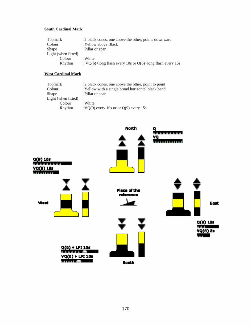
170
South Cardinal Mark
Topmark :2 black cones, one above the other, points downward Colour :Yellow above Black Shape :Pillar or spar Light (when fitted) Colour :White Rhythm : VQ(6)+long flash every 10s or Q(6)+long flash every 15s
West Cardinal Mark
Topmark :2 black cones, one above the other, point to point Colour :Yellow with a single broad horizontal black band Shape :Pillar or spar Light (when fitted) Colour :White Rhythm :VQ(9) every 10s or or Q(9) every 15s
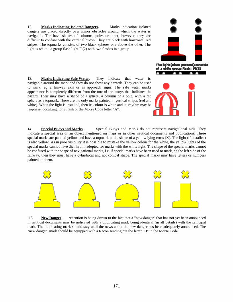
171
12. Marks Indicating Isolated Dangers. Marks indication isolated dangers are placed directly over minor obstacles around which the water is navigable. The have shapes of columns, poles or other; however, they are difficult to confuse with the cardinal buoys. They are black with horizontal red stripes. The topmarks consists of two black spheres one above the other. The light is white - a group flash light Fl(2) with two flashes in a group.
13. Marks Indicating Safe Water. They indicate that water is navigable around the mark and they do not show any hazards. They can be used to mark, eg a fairway axis or as approach signs. The safe water marks appearance is completely different from the one of the buoys that indicates the hazard. Their may have a shape of a sphere, a column or a pole, with a red sphere as a topmark. These are the only marks painted in vertical stripes (red and white). When the light is installed, then its colour is white and its rhythm may be isophase, occulting, long flash or the Morse Code letter "A".
14. Special Buoys and Marks. Special Buoys and Marks do not represent navigational aids. They indicate a special area or an object mentioned on maps or in other nautical documents and publications. These special marks are painted yellow and have a topmark in the shape of a yellow lying cross (X). The light (if installed) is also yellow. As in poor visibility it is possible to mistake the yellow colour for the white, the yellow lights of the special marks cannot have the rhythm adopted for marks with the white light. The shape of the special marks cannot be confused with the shape of navigational marks, i.e. if special marks have been used to mark, eg the left side of the fairway, then they must have a cylindrical and not conical shape. The special marks may have letters or numbers painted on them.
15. New Danger. Attention is being drawn to the fact that a "new danger" that has not yet been announced in nautical documents may be indicated with a duplicating mark being identical (in all details) with the principal mark. The duplicating mark should stay until the news about the new danger has been adequately announced. The "new danger" mark should be equipped with a Racon sending out the letter "D" in the Morse Code.

172
Emergency Wreck Marking Buoy 16. Introduction. At present new dangers are generally marked by cardinal or lateral buoys, although it is recognised that a number of authorities also deploy isolated danger marks. Recent grounding and collisions have indicated a need for a revision of how new dangers are marked, especially in an emergency. 17. The IALA Guideline No.1046 - Response Plan for the Marking of New Wrecks (June 2005) provides guidance to Authorities for an immediate, effective and well co-ordinated response in such a situation. The guidelines recommend procedures to be observed, as well as considerations to be taken into account with respect to all necessary measures when confronted with a new danger or an obstruction as a result of an incident within their area of responsibility. 18. Furthermore, there has been discussion with regards to the limitations of the present IALA Maritime Buoyage System when providing initial marking of new dangers. At present, new dangers are generally marked by cardinal or lateral buoys, although it is recognised that a number of Authorities also deploy isolated danger marks. Recent groundings and collisions have indicated a need for a revision of how new dangers are to be marked, especially in an emergency. As such, Guideline No.1046 provides guidance and recommendations for emergency wreck marking. 19. Scope and Objectives. This Recommendation provides details of a new buoy configuration, in addition to that already found in the IALA Maritime Buoyage System, which Authorities may consider deploying when responding to a new danger or obstruction. 20. Considerations. A new wreck can be very dangerous for shipping, not only when its exact position is unknown and is still unmarked, but even when the position is known and the wreck is properly marked. In the past, new wrecks have caused problems to other shipping resulting in damage, pollution and even loss of life. As detailed in the Guideline No.1046, Authorities should consider a range of responses including the deployment of guard ships, the use of AIS, temporary VTS and deployment of buoys amongst other risk mitigation measures. Whatever additional risk mitigation measures are initiated, a new danger must be physically marked. Weather conditions, sea state and unknown facts about the danger can all hamper timely marking. However, it is of great importance that the location of the danger is marked as soon as practicable and that this marking can be readily recognised by ships as a new hazard. The volume of traffic, background lighting and proliferation of Aids to Navigation (A to N) in the area may make the deployment of cardinal or lateral marks difficult for mariners to quickly identify a new danger in the initial stages of an incident. In these instances, authorities are invited to consider the deployment of an emergency wreck marking buoy that is specifically designed to mark new dangers. 21. Emergency Wreck Marking Buoy. The emergency wreck-marking buoy is designed to provide high visual and radio aid to navigation recognition. It should be placed as close to the wreck as possible, or in a pattern around the wreck, and within any other marks that may be subsequently deployed. The emergency wreck marking buoy should be maintained in position until:
(a) The wreck is well known and has been promulgated in nautical publications; (b) The wreck has been fully surveyed and exact details such as position and least depth above the wreck are known; and (c) A permanent form of marking of the wreck has been carried out.
22. Characteristics. The buoy has the following characteristics:
(a) A pillar or spar buoy, with size dependant on location. (b) Coloured in equal number and dimensions of blue and yellow vertical stripes (minimum of 4 stripes and maximum of 8 stripes).

173
(c) Fitted with an alternating blue* and yellow flashing light with a nominal range of 4 nautical miles (authorities may wish to alter the range depending on local conditions) where the blue and yellow 1 second flashes are alternated with an interval of 0.5 seconds.
B1.0s + 0.5s + Y1.0s + 0.5s = 3.0s (d) If multiple buoys are deployed then the lights should be synchronized. (e) Consideration should be given to the use of a racon Morse Code “D” and/or AIS transponder. (f) The top mark, if fitted, is to be a standing/upright yellow cross.
* The light characteristic was chosen to eliminate confusion with blue lights to identify law enforcement, security and emergency services. 23. A brief summary of the Maritime Buoyage System (Region 'A'), including the symbols and abbreviation used for charting the buoys under the system, is given in NP 735 (IALA Buoyage System) and Chart 5020 (INT 1).
174
Special Notice No.23: FORMER MINE DANGER AREAS: SWEPT ROUTES AND INSTRUCTIONS REGARDING EXPLOSIVES PICKED UP AT SEA.
1. Minefields were laid in many parts of World during World War II, Korean war and in a number of less extensive conflicts since then. Many of these minefields have been swept; others have had routes swept through them. These routes are mostly marked by buoys and have been used safely by Shipping for many years. 2. Due to the lapse of time, navigation through these minefields whether they have been swept or not is now considered no more dangerous from mines than from any other of the usual hazards to navigation; but in unswept areas a real danger still exists with regard to anchoring, fishing or any form of Submarine or seabed activity. Furthermore uncharted wrecks and shoals may lie in these areas, some of which are not covered by modern surveys. Former mine danger areas are mentioned in appropriate volumes of Sailing Directions. 3. Even in swept waters and routes there is a remote risk that mines may still remain, having failed to respond to orthodox sweeping methods. Mariners are therefore advised only to anchor in port approaches and established anchorages. In an emergency it is better to anchor in a swept route rather than in unswept waters. 4. Drifting mines may occasionally be sighted; the majority will probably be “lost” exercise mines. All drifting mines should be reported immediately to the Naval/Coast guard authorities on normal ship/shore communication channel; an “All Ships” broadcast should be made on VHF channel 16 to communicate the information to ships in the vicinity. The time of sighting and position of the mine is important in the reporting information. A drifting mine is best left for the naval experts to deal with. Rifle fire could pierce the casing and sink the mine without causing it to explode. It will then, if it is near the coast, get washed up on a beach or end up in a lethal state. 5. Mines, torpedoes, depth charges, bombs and other explosive missiles are sometime picked up in trawls, often in waters comparatively distant from where they were laid or dropped. Explosive weapons are dangerous even if they have been in the water for many years, and the following guidance is given in dealing with them:
(a) A suspected explosive weapon should not be landed on deck if it has been observed while trawl is still outboard. The trawl should be lowered and where possible towed clear of regular fishing ground before cutting away the net as necessary. The position of depth of the water where the mine was cut away should be passed to the Naval Authorities/Coastguard of fishery office. The eventual disposal of the mine will be greatly facilitated if the depth of water is no greater than 35 metres, the position very accurately plotted and, whenever possible, marked. (b) In the event of the weapon not being detected until the content of trawl have been discharged on deck, the skipper of the fishing vessel must decide whether to rid his ship of the weapon by passing it over the side or to make for the nearest port informing the Harbour Authority and Naval Authorities by radio without delay. His decision will depend upon the circumstances, but he should be guided by the following points:
(i) Great care should be taken to avoid bumping the weapon. (ii) If retained onboard it should be stowed on deck, away from the heat and vibration, firmly chocked and lashed to prevent movement. (iii) It should be kept covered and dumped down. (This is important because any explosive which may have become exposed to the atmosphere is liable to become very sensitive to shock if allowed to dry out.) (iv) The weapon should be kept on board for as short a time as possible. (v) If within two or three hours steaming of the coastline the safest measure will generally be to run towards the nearest port and lie a safe distance off shore to await the arrival of a Naval Explosive Ordnance Disposal Unit. Under no circumstances should the vessel bring the mine or weapon into harbour.

175
(c) Under no circumstances should attempts be made to clean the weapon for identification purposes, open it or tamper with it in any way. (d) A ship with an explosive weapon on board, or in her gear, should warn other ships in the vicinity giving her position and, if applicable, intended position of jettisoning.

176
Special Notice No.24: NOTICES TO MARINERS – Explanation of Terms 1. An explanation of the various commands used within Section II of fortnightly Indian Notices to Mariners is summarised below. The main text of the correction starts with one of the following five commands, usually in the order shown:
(a) INSERT is to be used for the insertion of all new data or, together with the DELETE command (see (e) below), when a feature has moved position sufficiently that the MOVE command (see (d) below) is not appropriate. For example: Delete feature and Insert in a different position. Note: The text to be written on a chart by insertion will appear in Italics in the printed notice. (b) AMEND is to be used when a feature remains in its existing charted position but has a change of characteristics, for example:
Amend light to, Fl.3s25m10M 16° 02'.20N, 73° 27'.30E When only the range of a light changes then it is sufficient to state Amend range of the light to, 10M 16° 02'.20N, 73° 27'.30E
(c) SUBSTITUTE is to be used when one feature replaces an existing feature and the position remains as charted. The new feature is always to be shown first, for example:
Substitute for (where is the new feature)
(d) MOVE is to be used for feature whose characteristics/descriptions remain unchanged, but they are to be moved small distances (the rule of thumb will be within a radius of 2.5cm from the previous charted position), for example:
Move starboard-hand conical buoy from: 15° 24'.50N, 73° 45'.00E To: 15° 24'.60N, 73° 45'.20E
(e) DELETE is to be used when feature are to be removed from the chart or, together with the INSERT command (see (a) above), when features are to be removed a significant distance such that the MOVE command is inappropriate.
2. Full details of chart correcting methods can be found in NP 294 ("How to keep your Admiralty charts Up-to-date" Edition 2010).

177
Special Notice No. 25: NATIONAL CLAIMS TO MARITIME JURISDICTION Source: www.un.org
1. The following list shows the breadth of sea (measured from the appropriate baselines in nautical miles) claimed respectively as territorial sea (TS), contiguous zone (CZ), exclusive economic zone (EEZ) and fishery zone (FZ), where no EEZ is claimed, as being under the state’s jurisdiction. The information is compiled from various, sometimes unofficial, sources; the absence of a limit from this list indicates that the information is not held.
2. The claims are published for information only.
Country TS CZ EEZ FZ
Albania 12
Algeria 12 24 32 or 52
Angola 12 24 200
Antigua and Barbuda 12 24 200
Argentina 12 24 200*
Australia 12*1 24 200
Bahamas 12 200
Bahrain 12 24
Bangladesh 12 18 200
Barbados2 12 200
Belgium 12 * 24 COORD √ 3
Belize 124 200
Benin 200
Bosnia and Herzegovina
Brazil 12 24 200 *
Brunei Darussalam 12 200
Bulgaria 12 24 200
Cambodia 12 24 200
Cameroon5 126 √
Canada 7 12 24 200
Cape Verde 12 24 200
Chile 12 * 24 * 200*
China 12 24 200
Colombia 12 200
Comoros 12 200
Congo 12 24 200
Cook Islands 12 200
Costa Rica 12 200*8
Côte d’Ivoire 12 200
Croatia 12 √ 9 COORD
Cuba 12 24 200 *10
Cyprus 12 24 200 *11
Democratic People's Republic of Korea 12 X12 200
Democratic Republic of the Congo 12 24 200/DLM
Denmark 13 1214 24 200/DLM15 20016

178
Djibouti 12 24 200
Dominica 12 24 200
Dominican Republic 12 24 200
Ecuador 20017
Egypt 12 24 √ 18
El Salvador 200
Equatorial Guinea 12* 200*
Eritrea19 12 √
Estonia 12 COORD20
COORD
Fiji 12* 200*
Finland 12* 21 1422 DLM *COORD
France23 12 24 200*24 /DLM
Gabon 12 24 200
Gambia 12 18 200
Georgia 12 24 DLM
Germany25 12*26 *COORD27
Ghana 12 24 200
Greece 628
Grenada 12 200
Guatemala 12 200
Guinea29 12 200
Guinea Bissau29 12 200
Guyana30 12 200
Haiti 12 24 200
Honduras 31 12 24 200
Iceland 12 200
India 12 24 200
Indonesia 12 200
Iran (Islamic Republic of ) 12 24 DLM
Iraq 12
Ireland 12 24 200 200*
Israel 12 DLM
Italy 12 √ 32
Jamaica 12 24 200
Japan 12* 33 24 200
Jordan 3
Kenya 12 200 */DLM
Kiribati 12 200
Kuwait 12
Latvia 12 34 DLM*35
Lebanon 12 *COORD
Liberia 12 24 200
Libyan Arab Jamahiriya36 12 DLM 62 COORD37
Lithuania 12* *COORD DLM*

179
Madagascar 12 24 200/DLM
Malaysia 12 200
Maldives 12 24 200
Malta36 12 24 25
Marshall Islands 12 24 200
Mauritania 12 24 200
Mauritius 12 24 200 /DLM
Mexico 12 24 200
Micronesia (Federated States of) 12 200
Monaco 12
Montenegro
Morocco 12 24 200
Mozambique 12 24 200
Namibia 12 24 200
Nauru 12 * 24 200 *
Netherlands25 12 * 24 COORD
New Zealand 12 *38 24 200 *39
Nicaragua31 12 24 200
Nigeria5 12 200
Niue 12 200
Norway13 12* 40 24 200* 20041
Oman 12 24 200
Pakistan 12 24 200
Palau 3 200 *42
Panama 12 24 200
Papua New Guinea 1243 200
Peru 20044
Philippines COORD45 200
Poland 12 DLM
Portugal 12 24 200
Qatar 12 24 DLM
Republic of Korea 12 24 200
Romania46 12* 24 200
Russian Federation 12 24 200
St. Kitts and Nevis 12 24 200
St. Lucia 12 24 200
St. Vincent and the Grenadines 12 24 200
Samoa 12 24 200
Sao Tome and Principe 12 200*
Saudi Arabia 12 18
Senegal 12 24 200
Seychelles 12 24 200*/DLM
Sierra Leone 12 24 200
Singapore 1247 √ 47
Slovenia 12/DLM √ 48
Solomon Islands 12 200

180
Somalia 200
South Africa 12 24 200
Spain 12 24 20049 COORD50
Sri Lanka 12 24 200
Sudan 12 18
Suriname29 12 200
Sweden 12 DLM
Syrian Arab Republic 12 24 200
Thailand 12 24 200
Timor-Leste 12 24 200
Togo 30 200
Tonga 12 2003
Trinidad and Tobago2 12* 24 200
Tunisia36 12 24 DLM √ 51
Turkey 6/1252 20053
Tuvalu 12 24 200
Ukraine 12 20046
UAE 12 24 200
UK 1254 20055 200or 12*56
United Republic of Tanzania 12 200 DLM
United States of America7 12 24 20057
Uruguay 12 * 24* 200*
Vanuatu 12 24 200
Venezuela 12 15 200
Viet Nam 1258 24 20059
Yemen19 12 24 200
1. The territorial sea boundaries between the islands of Aubusi, Boigu and Moimi and Papua New Guinea and the islands of Dauan, Kaumag and Saibai and Papua New Guinea, together with such other portion of the outer limit of the territorial sea of Saibai are determined by a treaty with Papua New Guinea. The territorial seas of the islands known as Anchor Cay, Aubusi Island, Black Rocks, Boigu Island, Bramble Cay, Dauan Island, Deliverance Island, East Cay, Kaumag Island, Kerr Islet, Moimi Island, Pearce Cay, Saibai Island, Turnagain Island and Turu Cay do not extend beyond three miles from the baselines. Deposit made in respect of the southern area of the Gulf of Carpentaria to include the part of the roadstead near the Port of Karumba in Queensland, and for drawing the limits of that roadstead.
2. See also the dispositif of the Award of the Arbitral Tribunal Constituted pursuant to article 287, and in accordance with Annex VII, of the United Nations Convention on the Law of the Sea in the Matter of an Arbitration between Barbados and the Republic of Trinidad and Tobago, 11 April 2006 3. Coterminous with the exclusive economic zone. 4. Three-mile limit applies from the mouth of Sarstoon River to Ranguana Caye. 5. See also ICJ Judgment of 10 October 2002 in the Case concerning the land and maritime boundary between Cameroon and Nigeria. 6. See article 45 of Law 96-06 of 18 January 1996 on the revision of the Constitution of 2 June 1972. 7. See also the judgment in the Case concerning Delimitation of the Maritime Boundary in the Gulf of Maine Area (Canada/United States of America) (ICJ, 1984) 8. Deposit made in respect of the Pacific Ocean coast.

181
9. The Decision on the Extension of the Jurisdiction of the Republic of Croatia in the Adriatic Sea of 3 October 2003 proclaimed only certain elements of the EEZ. The implementation of the legal regime of the “ecological and fisheries protection zone” of Croatia commenced twelve months after its establishment. 10. Deposit made in respect of the area of the Gulf of Mexico. 11. Deposit made in respect of the median line as referred to in the Delimitation Agreement between the Republic of Cyprus and the Arab Republic of Egypt. 12. 50-nautical mile military zone. Army Command Announcement of 1 August 1977. 13. See also the judgment in the North Sea Continental Shelf Cases (Federal Republic of Germany/Denmark; (ICJ, 1969). Also, see the judgment in the Case concerning Maritime Delimitation in the Area between Greenland and Jan Mayen (Denmark v. Norway) (ICJ, 1993)
14. 12 nm also for Faroe Islands (by Executive Decree No. 306 of 16 May 2002) and Greenland. As far as Greenland and Faroe Islands are concerned, the outer limit of the external territorial waters may be measured at a distance shorter than 12 nautical miles from the baselines. 15. Applies also to Greenland. 16. For Greenland and Faroe Islands. 17. Only between the continental territorial sea of Ecuador and its insular territorial sea around the Galápagos Islands. 18. In March 2003, Cyprus and Egypt signed an agreement on the delimitation of their respective exclusive economic zones. 19. See also the Eritrea-Yemen Arbitration: Award of the Arbitral Tribunal in the Second Stage: Maritime Delimitation, 17 December 1999 20. In some parts of the Gulf of Finland. 21. Extends, with certain exceptions, to 12 nautical miles, unless defined by geographical coordinates. In the Gulf of Finland, the outer limit of the territorial sea shall at no place be closer to the midline than 3 nautical miles, according to the Act amending the Act on the Limits of the Territorial Waters of Finland (981/95). 22. Two miles beyond the outer limits of the territorial sea. 23. See also the Continental Shelf Arbitration (France/United Kingdom) (1977) 24. Applies to the North Sea, the English Channel and the Atlantic Ocean from the Franco-Belgian border to the Franco-Spanish border, Saint Pierre and Miquelon, French Guiana, Réunion, New Caledonia, French Polynesia, French Southern and Antarctic Lands, Wallis and Futuna, Tromelin, Glorioso, Juan de Nova, Europa and Bassas da India Islands, Clipperton Island, Mayotte, Guadeloupe and Martinique. Deposit made in respect of Tromelin Island and Reunion Island. 25. See also the judgment of the North Sea Continental Shelf Cases (Federal Republic of Germany/Denmark; Federal Republic of Germany/Netherlands) (ICJ, 1969) 26. The deposit does not include delimitation lines with the Netherlands and Denmark. 27. The deposit does not include the delimitation with the Netherlands, Denmark and Poland. 28. Ten-mile limit applies for the purpose of regulating civil aviation. 29. See also the Maritime Boundary Delimitation Arbitration (Guinea/Guinea-Bissau) Arbitral Award, 1985 30. See also the dispositif of the Award of the Arbitral Tribunal Constituted pursuant to article 287, and in accordance with Annex VII, of the United Nations Convention on the Law of the Sea in the Matter of an Arbitration between Guyana and Suriname, 17 September 2007 31. See also the judgment of the Case concerning Territorial and Maritime Dispute between Nicaragua and Honduras in the Caribbean Sea, ICJ Judgment of 8 October 2007 32. See Law 61 of 8 February 2006 on the establishment of an ecological protection zone beyond the outer limit of the territorial sea. The outer limits are determined on the basis of an agreement with States concerned. Pending such agreements, the outer limit is determined by reference to a median line. 33. Three-mile limit applies to the Soya Strait, the Tsugaru Strait, the eastern and western channels of the Tsushima Strait and the Osumi Straits only. 34. Deposit made in respect of the maritime boundary with Estonia. 35. Deposit made in respect of the delimitation with Sweden. 36. See also the judgment of the Case concerning the Continental Shelf (Tunisia/Libyan Arab
182
Jamahiriya) (ICJ, 1982). Also, see Case concerning the Continental Shelf (Libyan Arab Jamahiriya/Malta) (ICJ, 1985) 37. Fisheries Protection Zone in the Mediterranean Sea, 21 June 2005. 38. Includes Tokelau. 39. Includes Tokelau. 40. Deposit includes mainland Norway, Svalbard, Jan Mayen and Bouvet Island. 41. Jan Mayen and Svalbard. Deposit includes the delimitation treaties with Denmark and Iceland in respect of Jan Mayen Island. 42. Deposit includes the line of delimitation between Palau and Micronesia. 43. Three nautical miles in certain areas. 44. Called “Maritime Dominion” in article 54 of the 1993 Constitution: “ ...In its maritime dominion, Peru exercises sovereignty and jurisdiction, without prejudice to the freedoms of international communication, in accordance with the law and the treaties ratified by the State...” 45. Polygon defined by coordinates. Claim extends beyond 12 nautical miles. 46. See also the judgment of the Maritime Delimitation in the Black Sea (Romania v. Ukraine) –ICJ, 3 February 2009 47. “Should the limits of its territorial sea or Exclusive Economic Zone overlap with claims of neighbouring countries, Singapore will negotiate with those countries with a view to arriving at agreed delimitations in accordance with international law.” 48. See “Ecological Protection Zone and Continental Shelf of the Republic of Slovenia Act” adopted on 4 October 2005. The delimitation of the ecological protection zone shall be effected by agreement with the neighbouring States. The Act provides for its provisional outer limits. 49. In the Atlantic Ocean. 50. In the Mediterranean Sea. 51. Up to 50-m isobath - Off the Gulf of Gabès. 52. Six nautical miles in the Aegean Sea, 12 nautical miles in the Black Sea. 53. In the Black Sea. 54. Also three nautical miles. (Three nautical miles in Anguilla, Guernsey, British Indian Ocean Territory, British Virgin Islands, Gibraltar, Monserrat and Pitcairn; 12 nautical miles in United Kingdom, Jersey, Bermuda, Cayman Islands, Falkland Islands (Malvinas), Isle of Man, St. Helena and Dependencies, South Georgia, South Sandwich Islands, and Turks and Caicos Islands.) | Note: A dispute exists between the Governments of Argentina and the United Kingdom of Great Britain and Northern Ireland concerning sovereignty over the Falkland Islands (Malvinas)]. 55. Bermuda, Pitcairn, South Georgia and South Sandwich Islands. 56. 12 nautical miles in Guernsey; 200 nautical miles in United Kingdom, Anguilla, British Indian Ocean Territory, British Virgin Islands, Cayman Islands, Falkland Islands (Malvinas), Monserrat, St. Helena and Dependencies, and Turks and Caicos Islands. Deposit made exclusively in respect of the British Indian Ocean Territory. | Note: A dispute exists between the Governments of Argentina and the United Kingdom of Great Britain and Northern Ireland concerning sovereignty over the Falkland Islands (Malvinas)]. 57. Includes Puerto Rico, U.S. Virgin Islands, American Samoa, Guam, Johnston Atoll, Palmyra Atoll, Midway Island, Wake Island, Jarvis Island, Kingman Reef, Howland Island, Baker Island, Northern Marianas, and Navassa Island. 58. Deposit made in respect of the delimitation with China in the Gulf of Tonkin. 59. Ibid. * Asterisks mark information which has been deposited with the Secretary-General in compliance with articles 16(2), 47(9), 75(2), 76(9), and/or 84(2) of the 1982 Convention. COORD: Defined by coordinates. DLM: Delimitation. The symbol DLM is used when national legislation establishes the limits of a given zone by reference to the delimitation of maritime boundaries with adjacent or opposite States (or to a median line in the absence of a maritime boundary delimitation agreement).

183
Special Notice No. 26: SATELLITE NAVIGATION SYSTEMS Source: www.gps.gov
1. The NAVSTAR Global Positioning System The Global Positioning System, commonly referred to as GPS, is a fully-functional satellite based navigation system. This is also officially named as Navigation Signal Timing and Ranging GPS (NAVSTAR GPS). A constellation of more than two dozen GPS satellites broadcasts precise timing signals by radio to the GPS receivers, allowing them to determine their location (longitude, latitude, and altitude) accurately in any weather, day or night, anywhere on the Earth’s surface. GPS has today become a vital global utility, indispensable for modern navigation on land, sea, and air around the world, as well as an important tool for map-making, and land surveying. GPS also provides extremely precise tools for time reference, required towards survey, telecommunications and various scientific researches, including the study of earthquakes.
2. The GPS space segment consists of a constellation of satellites transmitting radio signals to users. The US Air Force manages the constellation to ensure the availability of at least 24 GPS satellites, 95% of the time. For the past several years, it has been flying 31 operational GPS satellites, plus 3-4 decommissioned satellites ("residuals") that can be reactivated if needed. The constellation includes three spare satellites in orbit, in case of any failure. Each satellite circles around the Earth twice a day at an altitude of 20,200 kilometers (12,600 miles). The orbits are so aligned that at least four satellites are always within line of sight from almost any place on Earth. There are four active satellites in each of six orbital planes. Each orbit is inclined 55 degrees from the equatorial plane, and the right ascension of the ascending nodes is separated by sixty degrees. The flight paths of the satellites are measured by the monitor stations situated around the world. There is also a master control station which processes their combined observations and sends updates to the satellites through the control stations situated at various places on the earth surface. The updates synchronize the atomic clocks on board each satellite to within one microsecond and also adjust the ephemeris of the satellite’s internal orbital model to match the observations of the satellites from the ground.
3. Navigation Signal. GPS satellites broadcast three different types of data in the primary navigation signals. The first is the almanac which sends coarse time information with second precision, along with status information about the satellites. The second is the ephemeris, which contains orbital information that allows the receiver to calculate the position of the satellite at any point of time. These bits of data are folded into the 37,500 bit Navigation Message, which takes 12·5 minutes to send at 50 Hz. The satellites also broadcast two forms of accurate clock information, the Coarse Acquisition code or C/A code and the precise code or P-code. The former is normally used for most civilian navigation. It consists of a 1,023 bit long pseudo-random code broadcast at 1·023 MHz, repeating every millisecond. Each satellite sends a distinct C/A code, which allows them to be identified. The P-code is a similar code broadcast at 10·23 MHz, but it repeats only once per week. In normal operation, the so-called "anti-spoofing mode", the P code is first encrypted into the Y-code or P(Y), which can only be decrypted by units with a valid decryption key. All three signals, Navigation Message, C/A and P(Y) are mixed together and sent on the primary radio channel L1 at 1575·42 MHz. The P(Y) signal is also broadcast alone on the L2 channel i.e. 1227·60 MHz. Several additional frequencies are also used for unrelated purposes.
4. Position Calculation. The GPS system allows the receivers to accurately calculate their distance from the satellites. The receivers do this by measuring the time delay between the time when the satellite sent the signal and the local time when the signal was received. This delay multiplied by the speed of light gives the distance to that particular satellite. The receiver also calculates the position of the satellite based on information periodically sent in the same signal. By comparing the two i.e the position and the range, the receiver can discover its own location. Therefore to calculate its position, a receiver first needs to know the precise time. It is done by an internal crystal oscillator-based clock which is continually updated by the signals being sent in L1 (Carrier Frequency) from various satellites. At that point the receiver identifies the visible satellites by the distinct pattern in their C/A codes. It then looks up the ephemeris data for each satellite, which was captured from the Navigation Message and stored in memory. This data is used in a formula that calculates the precise location of the satellites at that point in time. Finally the receiver must calculate the time delay to each satellite. To do this, it produces an identical C/A sequence from a known seed number. The time delay is calculated by increasingly delaying the local signal and comparing it to the one received from the satellite. At some point the two signals will match up and that delay is the time needed for the signal to reach the receiver. The delay is generally between 65 and 85 milliseconds. The distance to that satellite can then be calculated directly, the so-called pseudo range. The receiver now has two key pieces of information i.e. an accurate estimate of the position of the satellite and an accurate measurement of the distance to that satellite. This tells the receiver that it lies on the surface of an imaginary sphere whose radius is that distance. To calculate the precise position, at least four such measurements are taken simultaneously. This

places the only be uswhether thsatellite, thequipped wtakes redun
5. So
(awredeustoindyre
(b
exanevtosadeankngemdeclm (c reposapow
receiver at thesed to place thhe receiver hashe time delay with extremelyndant measurem
ources of Erro
a) Multipwhere the radioeaching the recelay Multipathsed to address o filter out sindistinguishablynamic appliceflected signals
b) Ionosp
xpensive survend L2 frequencven without deo make this eaatellites. This wecodes the C/Any particular gnown surveyedeneral location
make better corelaying effect oloser to the gro
moving than the
c) GeomeThe co
eceiver at anyosition determatellites are bosition will be
were distributed
intersection ohe user withins lined up its and the range
y accurate atomments to re-cap
ors in GPS Sy
path Effects. o signals reflecceiver causes i
h, the receiver ishorter delay Mince it is onlle from routinations such ass quickly fail to
pheric and Atm
ey-grade civiliacies to measureecrypting the Psier, the militawould allow aA on L1. The eeographical ard location. Thisn. Several systerrections that aon the signal, tound in the trope billows in the
etric Dilutiononfiguration ofy given time
mination. For inbunched closee less accurate d evenly around
f the four imagn 300 kilometinternal C/A cto it, all depe
mic clocks, butpture the corre
ystem.
Like othct off surroundinaccuracy. A itself can recogMultipath fromly slightly de
ne fluctuationss cars and plao converge and
mospheric Int
an receivers cae atmospheric dP(Y) signal, as ary is considera direct compaeffects of the iea this effect cs correction, saems send this ina comparison othus resulting iposphere. The
e ionosphere, m
n of Precessif the satellitescan affect thenstance, if all together, thethan if those s
d the visible sk
184
ginary spheres.ters. Thus the code properly end on the acct this is not ecct clock inform
her radio signalding terrain; buvariety of rec
gnize the waywm the signal refelayed as coms in atmospheranes. When thd only the direc
erference.
an compare thdelay and appllong as the en
ring broadcastiarison of the Lionosphere arecan easily be caay “10 meters nformation oveof L1 and L2 in errors similaareas affected
making accurat
ion (GDOP).s in view to ae accuracy ofof the visible
e triangulatedsame satellitesky.
. Since the C/Amultiple meaor is "one off
curacy of the lconomically femation.
ls GPS signals uildings, canyo
ceivers’ techniqward signal andflecting off thempared to theric delay. Muhe GPS antennct signals resul
One of ththat, changspeed of thethrough thewhen the sagreater towamust travel ionosphere arough locatmodel can error. Sinceof radio wavthe second eliminate th
he difference bly the precise cncryption key iing the C/A si
L1 and L2 signe generally slowalculated by coto the east”, iser radio or othalone could. T
ar to those gened by these probe correction fo
a f e d
A pattern repeasurements are
f". The calculalocal clock. Theasible for a re
can also be afon walls, hardques mitigate d discard it. Sp ground. This fe direct signaultipath effectsna is moving,t in stable solu
he biggest probing atmosphere GPS signals e ionosphere. atellite is direcards the horizo
through the as the angle inction is known,be used to es
e the ionospherves differently
frequency bahis type of eetween the P(Y
corrections. This the same on gnal on L2 sta
nals using the w-moving andomparing the G also valid for er links to the
The amount oferated in the io
blems tend to bor these effects
ats every millisalso needed
ation of the pohe satellites theceiver. The sy
ffected by Muld ground etc. TMultipath Erro
pecialized anteform of Multipal, causing efs are much le, the false sol
utions.
blems for GPSric conditionsunpredictably The effect i
ctly overhead an, since the satgreater "thickcreases. Once , an internal mstimate and coric delay affecbased on their
and (L2) can error. Some mY) signal carriis correction caboth the chann
arting with thesame circuitry
d can easily beGPS-measured other receiverreceivers, allow
f humidity in aonosphere but lbe smaller in ar
more difficult
second, it can to determine
osition of the emselves are
ystem instead
ltipath issues, This delay in ors. For long
ennas are also path is harder ffects almost ess severe in lutions using
S accuracy is s change the
as they pass s minimized and becomes tellite signals
kness" of the the receiver's mathematical orrect for the cts the speed r frequencies,
be used to military and ied in the L1 an be applied nels. In order e Block III-R y that already tracked. For position to a
rs in the same wing them to air also has a located much rea and faster .

185
(d) Satellite Clock Bias Error. The internal satellite and receiver clocks have limited accuracy and they are not precisely synchronized. Since position computations are highly dependent on accurate timing information, small clock errors can cause significant errors in position computations. These errors can degrade the final calculated position by about 1·5 meters.
(e) Positional or Ephemeris Error. The navigation message from a satellite is sent out only every 12·5 minutes. In reality, the data contained in these messages tends to be "out of date" by an even larger amount. Consider the case when a GPS satellite is boosted back into a proper orbit, for some time following the maneuver, the receiver’s calculation of the satellite's position will be incorrect until it receives another ephemeris update. Additionally, the amount of accuracy sent in the ephemeris is limited by the bandwidth, using the data from the satellites alone limits its accuracy
(f) Selective Availability (SA). GPS included a feature called Selective Availability that introduced intentional errors of up to a hundred meters (300 ft) into the publicly available navigation signals, making it difficult to use for guiding long range missiles to precise targets. Additional accuracy was available in the signal, in an encrypted form only to the United States military applications, its allies and a few others, mostly government users. SA typically added signal errors of up to about 10 meters (30 ft) horizontally and 30 meters (100 ft) vertically. The inaccuracy of the civilian signal was deliberately encoded so as not to change very quickly. However later in May 2000, SA was removed thus increasing the accuracy.
6. Future Trends in GPS The entire constellation of GPS satellites currently provides two frequencies L1 and L2 with the civilian Coarse Acquisition code (C/A) on L1 and Military P Code encrypted to Y Code available on both L1 and L2. A major focus of the GPS modernization program is the addition of new navigation signals to the satellite constellation. The US government is in the process of fielding three new signals designed for civilian use: L2C, L5, and L1C. The legacy civil signal, called L1 C/A or C/A at L1, will continue broadcasting in the future, for a total of four civil GPS signals.
(a) L2C. L2C is the second civilian GPS signal, designed specifically to meet commercial needs. When combined with L1 C/A in a dual-frequency receiver, L2C enables ionospheric correction, a technique that boosts accuracy. Civilians with dual-frequency GPS receivers enjoy the same accuracy as the military (or better). For professional users with existing dual-frequency operations, L2C delivers faster signal acquisition, enhanced reliability, and greater operating range. L2C broadcasts at a higher effective power than L1 C/A signal, making it easier to receive under trees and even indoors. The name "L2C" refers to the radio frequency used by the signal (1227 MHz, or L2) and the fact that it is for civilian use. There are also two military signals at the L2 frequency
(b) L5. The name "L5" refers to the U.S. designation for the radio frequency used by the signal (1176 MHz). L5 is the third civilian GPS signal, designed to meet demanding requirements for safety-of-life transportation and other high-performance applications. L5 is broadcast in a radio band reserved exclusively for aviation safety services. It features higher power, greater bandwidth, and an advanced signal design. Future aircraft will use L5 in combination with L1 C/A to improve accuracy (via ionospheric correction) and robustness (via signal redundancy). When used in combination with L1 C/A and L2C, L5 will provide a highly robust service. Through a technique called trilaning, the use of three GPS frequencies may enable sub-meter accuracy without augmentations, and very long range operations with augmentations.
(c) L1C. The name "L1C" refers to the radio frequency used by the signal (1575 MHz, or L1) and the fact that it is for civilian use. L1C is the fourth civilian GPS signal, designed to enable interoperability between GPS and international satellite navigation systems. L1C features a Multiplexed Binary Offset Carrier (MBOC) modulation scheme that enables international cooperation while protecting U.S. national security interests. The United States and Europe originally developed L1C as a common civil signal for GPS and Galileo. Other satellite navigation providers are adopting L1C as a future standard for international interoperability. Japan's Quasi-Zenith Satellite System (QZSS), the Indian Regional Navigation Satellite System (IRNSS), and China's Compass system all plan to broadcast L1C.
7. In 2009, the Air Force successfully broadcast an experimental L5 signal on the GPS IIR-20(M) satellite. The first GPS IIF satellite with a full L5 transmitter was launched in May 2010. The first three GPS IIR-M satellites with the new

186
L2C codes have been launched and the next launch is scheduled in near future. The L1C code, compatible with Galileo L1C is due for lunch in 2013 on the first of the GPS IIIA satellites.
8. With the increased number of tracking stations, the coverage at high altitudes has also been increased drastically. Thus the broadcast orbit and clock accuracy have also reportedly improved by as much as 15- 20%. In addition within next two years few more tracking stations are due to be added.
9. Dual frequency L2C capable receivers will be capable of accessing the L2C signal with 10 to 20 dB greater signal strength than the currently used cross- correlation techniques, resulting in more reliable dual-frequency performance in areas of poor signal. The full benefits of L2C will not be available until the majority of the current satellite constellations have been replaced by L2C- capable satellites. Then we may have low- power, consumer-grade and dual-frequency GPS receivers. The future L5 will feature a higher power signal, higher bandwidth and enhanced signal structure for superior performance. Higher power will help overcome the Distance Measuring Equipment (DME), which shares the (Aeronautical Radio Navigation Service)ARNS band that includes L5.
10. The introduction of L1C will be in addition to the existing C/A code, ensuring that existing GPS equipment work. L1C is currently being designed to be compatible with Galileo. Future tri-frequency GPS receivers will be better able to determine ionospheric and tropospheric delay, leading to greater confidence in determined position, especially height. In addition there will be three possible signal pairs, and this will improve reliability and robustness of integer selection of Real time Kinematics (RTK) precise positioning and the range at which integers can be successfully resolved from a single RTK base station.
Differential Global Positioning System
11. The signals and data from the GPS satellites may exhibit some inherent errors, such as errors due to wave propagation, inaccuracies on satellite orbit predictions and clock drifts. All such errors affect the positioning accuracy in traditional GPS receivers. On average, Horizontal Positioning Errors may be as high as 30 to 50 meters for a 95% probability. Of course, the user may occasionally notice better accuracies but in the long run, for example over one or more years, problems of repeatability will lead to the above figures. 12. Furthermore, both the signals and the data available to civilian GPS users are subject to international impairment through the Selective Availability process (SA) that may be activated at any time by the US Department of Defence (DOD). SA will be systematically implemented when the global 3- dimension positioning capability of the GPS system is achieved. The effect of Selective Availability is a decrease in position and speed accuracies achievable worldwide, to a level consistent with the security requirements set out by the US military. 12. These errors, intentional or inherent in the GPS system when used, have a common characteristic: high degree of correlation in space. A high degree of space correlation means that the errors observed by all GPS receivers locked on a given satellite will be virtually the same over an area of several thousand miles. 14. Principle. The basic principle of the Differential GPS (DGPS) technique consists of observing each satellite separately and measuring the error brought about by the satellite, using a receiver installed at a station with known coordinates. The DGPS technique relies on the error measured for each satellite as shown on the diagram. The technique consists of directly comparing the geographical positions computed by two receivers (one of which still being stationary). One could never be sure that both receivers used the same satellites to compute the respective positions, which might lead to large errors. The deviations called corrections, observed on each satellite, incorporated in digital message, must be broadcast to Differential GPS users through a specific highly reliable radio frequency link called Radio Technical commission for Mariners Special Committee (RTCM SC108).

187
(Principle of Differential GPS)
15. Errors Reduced by Differential GPS -
Source Uncorrected With Differential Ionosphere 0-30m Mostly removed Troposphere 0-30m All Removed Signal Noise 0-10m All Removed Orbit Data 1-5m All Removed Clock drift 0-1·5m All Removed Multipath 0-1m Not Removed Receiver Noise ~ 1m Not Removed Selective Availability 0-70m All Removed
GLONASS
16. GLONASS, acronym for Globalnaya Navigatsionnaya Sputnikovaya Sistema or Global Navigation Satellite System, is the Russian equivalent of the United State's GPS system and the European Union's Galileo positioning system is the GLObal NAvigation Satellite System (GLONASS), a radio satellite navigation system.
17. The complete GLONASS constellation consists of 24 satellites, placed in three orbital planes. Each plane contains eight satellites identified by "slot" number, which defines the corresponding orbital plane and the location within the plane: 1-8, 9-16, 17-24. The three orbital planes are separated by 120°, and the satellites equally spaced within the same orbital plane, 45° apart. The GLONASS orbits are roughly circular, with an inclination of about 64·8° and a semi-major axis of 25,440 km. The planes themselves have 15° argument of latitude displacement. GLONASS constellation orbits the Earth at an altitude of 19,100 km (slightly lower than that of the GPS satellites). Each satellite completes an orbit in approximately 11 hours 15 minutes. The spacing of the satellites in orbits is arranged so that a minimum of 5 satellites are in view at any given time. By 2010, GLONASS had achieved 100% coverage of Russia's territory and in October 2011, the full orbital constellation of 24 satellites was restored, enabling full global coverage. Four more GLONASS-M satellites (reserve ones) were launched in 2011, and subsequently the GLONASS-K generation will come to replace the older satellites of the system.
18. The GLONASS Constellation is operated by Ground-based Control Complex (GCS). It consists of the System Control Center (SCC) (Golitsyno-2, Moscow region) and a several Command Tracking Stations (CTS) are placed over a

188
wide area of Russia. The Ground Control Center and Time Standards is located in Moscow and the telemetry and tracking stations are in Saint Petersburg, Ternopol, Eniseisk, and Komsomolsk-na-Amure. The CTSs track the GLONASS satellites in view and accumulate ranging data and telemetry from the satellites signals. The information from CTSs is processed at the SCC to determine satellite clock and orbit states and to update the navigation message of each satellite. This updated information is transmitted to the satellites via the CTSs, which also used for transmitting of control information. The CTSs ranging data is periodically calibrated using a laser ranging devices at the Quantum Optical Tracking Stations which are within GCS. Each GLONASS satellite specially carries laser reflectors for this purpose. The synchronization of all the processes in the GLONASS system is very important for its proper operability. There is the Central Synchronizer within GCS to meet this requirement. The Central Synchronizer is high-precise hydrogen atomic clock which forms the GLONASS system time scale. The onboard time scales (on a basis of satellite cesium atomic clocks) of all the GLONASS satellites are synchronized with the State Etalon UTC (CIS) in Mendeleevo, Moscow region, through the GLONASS System Time scale.
19. The GLONASS satellites are equipped with cesium clocks, daily frequency instabilities of which are not more than 5x10E (-13). This provides an accuracy of satellite time synchronization relative to GLONASS System Time of about 15 nanoseconds (one sigma) , with clocks corrections uploaded to the satellite twice a day. GLONASS System Time (GLONASST) is generated on the basis of Central Synchronizer time. Daily instabilities of Central Synchronizer hydrogen clocks are not more than 5x10E (-14).
20. The GLONASS system has two types of navigation signal: standard precision navigation signal (SP) and high precision navigation signal (HP). The signals use similar DSSS encoding and binary phase-shift keying (BPSK) modulation as in GPS signals. All GLONASS satellites transmit the same code as their SP signal; however each transmits on a different frequency using a 15-channel frequency division multiple access (FDMA) technique spanning either side from 1602.0 MHz, known as the L1 band. The HP signal (L2) is broadcast in phase quadrature with the SP signal, effectively sharing the same carrier wave as the SP signal, but with a ten-times-higher bandwidth than the SP signal. At peak efficiency, the SP signal offers horizontal positioning accuracy within 5–10 meters, vertical positioning within 15 meters, a velocity vector measuring within 10 cm/s, and timing within 200 ns, all based on measurements from four first-generation satellites simultaneously; newer satellites such as GLONASS-M improve on this. The more accurate HP signal is available for authorized users, such as the Russian Military,
21. GLONASS receiver automatically receives navigational signals from at least 4 satellites and measures their pseudo ranges and velocities. Simultaneously it select and process navigation message from satellites signals. Computer of GLONASS receiver process all the input data and calculate three coordinates, three components of velocity vector, and precise time. The GLONASS Navigation message form a part of the navigation radio signal which includes:
(a) The broadcast ephemerides (b) Satellites time scale shifts relative to the GLONASS System Time and UTC. (c) Time marks and (d) The GLONASS almanac
22. The ephemerides are the exact coordinates of the satellites in x, y, z and its first and second derivatives describing its location in PZ-90 geocentric reference system (reference frame for GLONASS). Almanac keep an information about all GLONASS satellites and includes Keplerian elements of orbits, coarse shifts of every on-board time scale relative to GLONASS system time and "healthy" or “unhealthy” flag of each satellite.
23. Since 2008, new CDMA signals are being researched for use with GLONASS. The latest Glonass-K1 satellites to be launched in 2011–2012 will introduce an additional open CDMA signal for testing purposes, located in the L3 band at 1202.025 MHz. Glonass-K2 satellites, to be launched in 2013–2015, will relocate the L3 signal to 1207.14 MHz and add an additional open CDMA signal located at 1575.42 MHz in the L1 band; subsequent Glonass-KM satellites to be launched after 2015 will feature additional open CDMA signals – one on existing L1 frequency, one at 1242 MHz in the L2 band, and one at 1176.45 MHz in the L5 band. Glonass-KM will probably broadcast obfuscated CDMA signals in existing L1 and L2 bands. With the introduction of CDMA signals, the constellation will be expanded to 30 active satellites by 2020; this may require eventual deprecation of FDMA signals
24. The first GLONASS-K satellite was successfully launched on 26 February 2011. GLONASS-K is a substantial improvement over the second generation GLONASS-M satellites. It is the first unpressurised GLONASS satellite with a

189
much reduced mass (750 kg versus 1,450 kg of GLONASS-M). It has an operational lifetime of 10 years, compared to the 7-year lifetime of GLONASS-M. It will transmit more navigation signals to improve the system's accuracy, including new CDMA signals in the L3 and L5 bands which will use modulation similar to modernized GPS, Galileo and Compass. The new satellite's advanced equipment made solely from Russian components has the ability of doubling of GLONASS' accuracy. As with the previous satellites, these are 3-axis stabilized, nadir pointing with dual solar arrays. The system's ground segment is also to undergo improvements. As of early 2012, sixteen positioning ground stations are under construction in Russia and in the Antarctic bases. New stations will be built around the southern hemisphere from Brazil to Indonesia. Together, these improvements are expected to bring GLONASS' accuracy to 0.6 meters or better by 2020 EGNOS 25. The European Geostationary Navigation Overlay Service (EGNOS) is the first pan-European satellite navigation system. It augments the US GPS satellite navigation system and makes it suitable for safety critical applications such as flying aircraft or navigating ships through narrow channels. Consisting of three geostationary satellites and a network of ground stations, EGNOS achieves its aim by transmitting a signal containing information on the reliability and accuracy of the positioning signals sent out by GPS. It allows users in Europe and beyond to determine their position to within 1.5 metres. 26. EGNOS is a joint project of ESA (European Space Agency), the European Commission and Eurocontrol, the European Organisation for the Safety of Air Navigation. It is Europe’s first activity in the field of Global Navigation Satellite Systems (GNSS) and is a precursor to Galileo, the full global satellite navigation system under development in Europe. After the successful completion of its development, ownership of EGNOS was transferred to the European Commission in April 2009. EGNOS operations are now managed by the European Commission through a contract with an operator based in France, the European Satellite Services Provider. 27. The EGNOS Open Service has been available since 1 October 2009. EGNOS positioning data are freely available in Europe through satellite signals to anyone equipped with an EGNOS-enabled GPS receiver. The EGNOS Safety of Live service has been officially declared available for aviation on 02 March 2011. Space-based navigation signals have become usable for the safety-critical task of guiding aircraft; vertically as well as horizontally during landing approaches. GALILEO 28. Galileo is a satellite navigation system currently being built by the European Union (EU) and European Space Agency (ESA). Galileo is a global navigation satellite system, providing a highly accurate, guaranteed global positioning service under civilian control. It will be inter-operable with GPS and GLONASS, the two other global satellite navigation systems. A user will be able to take a position with the same receiver from any of the satellites in any combination. By offering dual frequencies as standard, however, Galileo will deliver real-time positioning accuracy down to the meter range, which is unprecedented for a publicly available system.
29. ESA’s first two navigation satellites, GIOVE-A and –B, were launched in 2005 and 2008 respectively, reserving radio frequencies set aside for Galileo by the International Telecommunications Union and testing key Galileo technologies. Thereafter up to four operational satellites were launched in the timeframe of 2005-2006 to validate the basic Galileo space and related ground segment. On 21 October 2011 the first two of four operational satellites designed to validate the Galileo concept in both space and on Earth were launched. Two more will follow in 2012. Once this In-Orbit Validation (IOV) phase has been completed, additional satellites will be launched to reach Initial Operational Capability (IOC) around mid-decade. A range of services will be extended as the system is built up from IOC to reach the Full Operational Capability (FOC) by this decade’s end.
30. The fully deployed Galileo system will consists of 30 satellites (27 operational + 3 active spares), positioned in three circular Medium Earth Orbit (MEO) planes at 23,222 km altitude above the Earth, and at an inclination of the orbital planes of 56 degrees with reference to the equatorial plane. Once this is achieved, the Galileo navigation signals will provide good coverage even at latitudes up to 75 degrees north, which corresponds to the North Cape, and beyond. The satellites will be spread evenly around each plane and will take about 14 hours to orbit the Earth. One satellite in each plane will be a spare; on stand-by should any operational satellite fail. The large number of satellites together with the optimization of the constellation, and the availability of the three active spare satellites, will ensure that the loss of one satellite has no discernible effect on the user. The orbit has been chosen to optimize the average elevation to 25 degrees for

190
better performance in urban canyons and northerly latitudes, as opposed to the original GPS orbit that was optimized for a 10-degree elevation for military purpose.
31. When in operation, it will use two ground operations centres, near Munich, Germany and in Fucino, Italy. The system was initially expected to become operational by 2012, but that date has been repeatedly moved back. As of 2011, initial service is expected around 2014 and completion by 2019.
32. Each Galileo satellite will broadcast 10 different navigation signals, making it possible for Galileo to offer the open (OS), safety-of-life (SOL), commercial (CS) and public regulated services (PRS). Presently, Galileo is scheduled to provide early services in 2014/2015.
33. Galileo receivers receive the signals broadcast by the Galileo satellites and process them to compute position. Through this processing, the receivers extract measurements giving an indication of the distance from the user to the satellite. They also decode the Galileo navigation data, which contain fundamental pieces of information for computing the user position such as the position of the satellites or the satellite clock errors as determined by the Galileo ground segment and up-linked regularly to the Galileo constellation. The frequencies used by the satellites are within the 1.1 to 1.6 GHz band, a range of frequencies particularly well suited for mobile navigation and communication services. 34. The Galileo system once fully operational is expected to provide the following navigation services:-
(a) Open Service (OS). This will be free for anyone to access. The OS signals will be broadcast in two bands, at 1164–1214 MHz and at 1563–1591 MHz. Receivers will achieve an accuracy of <4 m horizontally and <8 m vertically if they use both OS bands. Receivers that use only a single band will still achieve <15 m horizontally and <35 m vertically, comparable to what the civilian GPS C/A service provides today. It is expected that most future mass market receivers, such as automotive navigation systems, will process both the GPS C/A and the Galileo OS signals, for maximum coverage.
(b) Commercial Service (CS). This is the encrypted version available on Commercial terms. This service will offer an accuracy of better than 1 m. The CS can also be complemented by ground stations to bring the accuracy down to less than 10 cm. This signal will be broadcast in three frequency bands, the two used for the OS signals, as well as at 1260–1300 MHz.
(c) Public Regulated Service (PRS) and Safety of Life Service (SoL) Service. Both these services will be available in encrypted version and will provide accuracy comparable to the Open Service. Their main aim is robustness against jamming and the reliable detection of problems within 10 seconds. They will be targeted at security authorities (police, military, etc.) and safety-critical transport applications (air-traffic control, automated aircraft landing, etc.), respectively. In addition, the Galileo satellites will be able to detect and report signals from Cospas-Sarsat search-and-rescue beacons in the 406.0–406.1 MHz band, which makes them a part of the Global Maritime Distress Safety System.
BEIDOU 35. The BeiDou Navigation System (or BeiDou (Compass) Navigation Satellite System is a project by China to develop an independent satellite navigation system. It may refer to either one or both generations of the Chinese navigation system. The first BeiDou system, officially called BeiDou Satellite Navigation Experimental System, or known as BeiDou-1, consists of 3 satellites and has limited coverage and applications. It has been offering navigation services mainly for customers in China and from neighboring regions since 2000.The second generation of the system, known as Compass or BeiDou-2, which will be a global satellite navigation system consisting of 35 satellites, is still under construction. It became operational with coverage of China in December 2011. It is planned to offer services to customers in Asia-Pacific region by 2012 and the global system should be finished by 2020.

191
Experimental System (BeiDou-1).
36. The Compass Navigation Satellite Experimental System, or BeiDou 1 in its Chinese name, is the three-satellite constellation developed by China Academy of Space Technology (CAST). The system provides all-weather, two-dimensional positioning data for both military and civilian users. This system integrates advantages of traditional astronomy navigation and position and ground radio navigation and position, equal to an air radio navigation station, which can decide users, latitude, longitude and altitude positions at any time and at any place.
37. This System covers the region between Longitude 70°-140°E and Latitude 5°-55°N. Two satellites are positioned in geosynchronous orbit at 80°E and 140°E Longitude respectively. The third satellite which is a spare is positioned at 110·5° E Longitude. The satellites are capable of communication and horizontal positioning for China’s military within their region. The ground systems include the central control station, three ground tracking stations for orbit determination (at Jamushi, Kashi and Zhanjiang), ground correction stations, and user terminals (receivers/transmitters). The satellites transmit at 2491·75+/-4·08MHz and the ground receiver can transmit back to the satellite on 1615·68MHz. The BeiDou reference-frame is the Beijing 1954 Coordinate System, with time referenced to China UTC as determined in Beijing. The system provides positioning data of up to 100m accuracy. By using ground correction stations, the accuracy can be increased to 20m. The BeiDou-1 system uses a large-size transmitter/receiver user terminal due to its dual-way transmission operation method. 38. Method of Operation. The central control station sends inquiry signals to the users via two satellites. When the user terminal received the signal from one satellite, it sends the responding signal back to both satellites. The central station receives the responding signals sent by the user from two satellites, and calculates the user’s two dimensional position based on the time difference between the two signals. This position is then compared with the digital territorial map stored in the database to get the three dimensional position, which is then sent back to the user via satellites using encrypted communications. The user can also transmit encrypted text messages (up to 120 Chinese characters) to the central station via the satellites. Since the BeiDou system requires dual-way transmissions between the user and central control station via satellites at high-altitude geostationary orbit, its user segment needs extra space for transmitter and a more-powerful battery. Therefore the BeiDou system’s user segments are much bigger, heavier and more expensive compared to GPS user receivers. Additionally, the number of users can be served by the system is limited by the communication capacity of the network.
Global System (BeiDou-2 or Compass navigation system)
39. BeiDou-2 is not an extension to the existing BeiDou-1. The new system will be a constellation of 35 satellites, which include 5 geostationary orbit satellites for backward compatibility with BeiDou-1, and 30 non-geostationary satellites (27 in medium earth orbit and 3 in inclined geostationary orbit), that will offer complete coverage of the globe. There will be two levels of service provided; free service to civilians and licensed service to Chinese government and military users:-
(a) The free service will have a 10 meter location-tracking accuracy, will synchronize clocks with an accuracy of 10 ns, and measure speeds within 0.2 m/s.
(b) The licensed service will be more accurate than the free service, can be used for communication,and will supply information about the system status to the users.
Compass-M1
40. Compass-M1 is an experimental satellite launched for signal testing and validation and for the frequency filing on 14 April 2007. The role of Compass-M1 for Compass is similar to the role of GIOVE satellites for Galileo. The orbit of Compass-M1 is nearly circular, has an altitude of 21,150 km and an inclination of 55.5 degrees.
41. In December 2011, the system went into operation on a trial basis. During this trial run, Compass will offer positioning accuracy to within 25 meters, but the precision will improve as more satellites are launched. When the system is officially launched, it pledges to offer general users positioning information accurate to the nearest 10 m, measure speeds
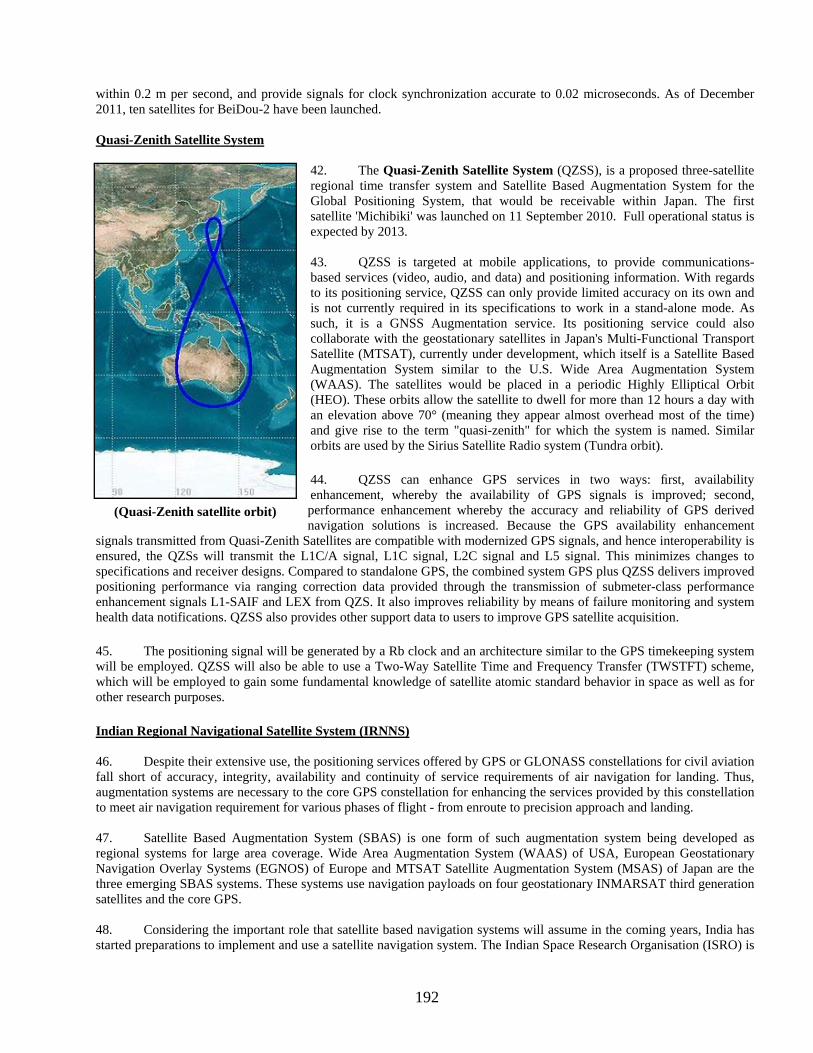
192
within 0.2 m per second, and provide signals for clock synchronization accurate to 0.02 microseconds. As of December 2011, ten satellites for BeiDou-2 have been launched. Quasi-Zenith Satellite System
42. The Quasi-Zenith Satellite System (QZSS), is a proposed three-satellite regional time transfer system and Satellite Based Augmentation System for the Global Positioning System, that would be receivable within Japan. The first satellite 'Michibiki' was launched on 11 September 2010. Full operational status is expected by 2013. 43. QZSS is targeted at mobile applications, to provide communications-based services (video, audio, and data) and positioning information. With regards to its positioning service, QZSS can only provide limited accuracy on its own and is not currently required in its specifications to work in a stand-alone mode. As such, it is a GNSS Augmentation service. Its positioning service could also collaborate with the geostationary satellites in Japan's Multi-Functional Transport Satellite (MTSAT), currently under development, which itself is a Satellite Based Augmentation System similar to the U.S. Wide Area Augmentation System (WAAS). The satellites would be placed in a periodic Highly Elliptical Orbit (HEO). These orbits allow the satellite to dwell for more than 12 hours a day with an elevation above 70° (meaning they appear almost overhead most of the time) and give rise to the term "quasi-zenith" for which the system is named. Similar orbits are used by the Sirius Satellite Radio system (Tundra orbit).
44. QZSS can enhance GPS services in two ways: first, availability enhancement, whereby the availability of GPS signals is improved; second, performance enhancement whereby the accuracy and reliability of GPS derived navigation solutions is increased. Because the GPS availability enhancement
signals transmitted from Quasi-Zenith Satellites are compatible with modernized GPS signals, and hence interoperability is ensured, the QZSs will transmit the L1C/A signal, L1C signal, L2C signal and L5 signal. This minimizes changes to specifications and receiver designs. Compared to standalone GPS, the combined system GPS plus QZSS delivers improved positioning performance via ranging correction data provided through the transmission of submeter-class performance enhancement signals L1-SAIF and LEX from QZS. It also improves reliability by means of failure monitoring and system health data notifications. QZSS also provides other support data to users to improve GPS satellite acquisition.
45. The positioning signal will be generated by a Rb clock and an architecture similar to the GPS timekeeping system will be employed. QZSS will also be able to use a Two-Way Satellite Time and Frequency Transfer (TWSTFT) scheme, which will be employed to gain some fundamental knowledge of satellite atomic standard behavior in space as well as for other research purposes.
Indian Regional Navigational Satellite System (IRNNS) 46. Despite their extensive use, the positioning services offered by GPS or GLONASS constellations for civil aviation fall short of accuracy, integrity, availability and continuity of service requirements of air navigation for landing. Thus, augmentation systems are necessary to the core GPS constellation for enhancing the services provided by this constellation to meet air navigation requirement for various phases of flight - from enroute to precision approach and landing. 47. Satellite Based Augmentation System (SBAS) is one form of such augmentation system being developed as regional systems for large area coverage. Wide Area Augmentation System (WAAS) of USA, European Geostationary Navigation Overlay Systems (EGNOS) of Europe and MTSAT Satellite Augmentation System (MSAS) of Japan are the three emerging SBAS systems. These systems use navigation payloads on four geostationary INMARSAT third generation satellites and the core GPS. 48. Considering the important role that satellite based navigation systems will assume in the coming years, India has started preparations to implement and use a satellite navigation system. The Indian Space Research Organisation (ISRO) is
(Quasi-Zenith satellite orbit)

193
developing a satellite based navigation system, called Indian Regional Navigation Satellite System (IRNSS), with a constellation of 7 satellites and complementary ground infrastructure. 49. Development. The IRNSS system is planned to be made operational by end of 2014. Government of India had approved the IRNSS project at a total cost of Rs. 1420.00 crores in May 2006 for both space and ground infrastructure. IRNSS-1, the first of the seven satellites planned for IRNSS program is scheduled to be launched on-board PSLV-C21 in late 2012. IRNSS is planned to be an independent regional navigation system covering an area of about 1500kms around India. 50. Description. The INRSS will consist of three segments: space, ground and user. The space segment would consist of a constellation of seven satellites. Three of the satellites in the constellation will be placed in geostationary orbit (GEOs) located at 34° E, 83° E and 132° E and the remaining four in geosynchronous orbit (GSO) at an inclination angle of 29° to the equatorial plane with longitude crossing at 55° and 111° East. Such an arrangement would mean all seven satellites would have continuous radio visibility with Indian control stations. The satellite payloads would consist of atomic clocks and electronic equipment to generate the navigation signals. The navigation signals themselves would be transmitted in the S-band frequency (2-4 GHz) and broadcast through a phased array antenna to maintain required coverage and signal strength. The satellites would weigh approximately 1,330 kg and their solar panels generate 1,400 watts. IRNSS system provides dual frequency (S & L5 band) usage. At present one down link in S-band and three down links in L5 band are planned. The System is intended to provide an absolute position accuracy of better than 20 meters throughout India and within a region extending approximately 1,500 to 2,000 km around it.
51. The ground segment of IRNSS constellation would consist of a Master Control Center (MCC), ground stations to track and estimate the satellites' orbits and ensure the integrity of the network (IRIM), and additional ground stations to monitor the health of the satellites with the capability of issuing radio commands to the satellites (TT&C stations). The MCC would estimate and predict the position of all IRNSS satellites, calculate integrity, makes necessary ionospheric and clock corrections and run the navigation software. In pursuit of a highly independent system, an Indian standard time infrastructure would also be established.
GAGAN
52. The Ministry of Civil Aviation has decided to implement an indigenous Satellite-Based Regional GPS Augmentation System also known as Space-Based Augmentation System (SBAS) as part of the Satellite-Based Communications, Navigation and Surveillance (CNS)/Air Traffic Management (ATM) plan for civil aviation. The Indian SBAS system has been given an acronym GAGAN - GPS Aided GEO Augmented Navigation. A national plan for satellite navigation including implementation of Technology Demonstration System (TDS) over the Indian air space as a proof of concept has been prepared jointly by Airports Authority of India (AAI) and ISRO The space segment of GAGAN will be in the form of an electronic device that works on two frequencies and well matched with GPS system. The ground segment consisting of eight Indian Reference Stations (INRESs), one Indian Master Control Centre (INMCC), one Indian Land Uplink Station (INLUS) and associated navigation software and communication links has been installed. Preliminary System Acceptance Test has indicated that the position accuracies available are good.

194
(Gagan Coverage From 82 Deg East)
53. The GAGAN system is part of a global initiative endorsed by the International Civil Aviation Organisation (ICAO) and would be implemented in three phases- the Technology Demonstration System (TDS), initial experimental phase and final operational phase. While ISRO will be involved in driving the project, AAI will provide the requisite financial, technical manpower and all the other supplementary support for the project.
54. A national plan for satellite navigation including implementation of Technology Demonstration System (TDS) over the Indian air space as a proof of concept has been prepared jointly by Airports Authority of India (AAI) and ISRO. TDS was successfully completed during 2007 by installing eight Indian Reference Stations (INRESs) at eight Indian airports and linked to the Master Control Center (MCC) located near Bangalore. The GAGAN-TDS programme consisted of a monitor and control centre and a land uplink station in Bangalore and reference stations in eight locations in India. This is the first phase of the project to implement the space-based navigation system in the Indian airspace. The PSAT (Preliminary System Acceptance Testing) has been successfully completed in Dec 2010. The first GAGAN navigation payload slated on GSAT-8 was launched on May 21, 2011. The second GAGAN payload is scheduled to be launched on GSAT-10 in the first quarter of 2012. The third GAGAN payload is planned on another GEO satellite
55. Presently the Indian airspace is falling between coverage area of European Geostationary Navigation Overlay System (EGNOS) on the West and Multi Functional Transport Satellites (MTSAT) Satellite-Based Augmentation System (MSAS) (Japan) on the East. Therefore GAGAN will help to form a bridge between the coverage areas of EGNOS and MSAS, and will also facilitate seamless navigation of the aircraft from West-East and vice-versa. In addition, India which is well placed at the axis of routes connecting Europe with Southeast Asia, having an indigenous satellite-based regional GPS augmentation system, could gain both in terms of market and strategic importance. This system would augment the existing Global Positioning System (GPS) satellites. The latest information shows three geo-stationary satellites in orbit. There are also four geo-synchronous satellites in figure of eight orbits over India region. GAGAN will be transmitted on L1 and L5 transponders aboard the Indian Communication Satellite (Geosynchronous satellite 4) (GSAT4), which will be launched by India’s Geosynchronous satellite Launch Vehicle (GSLV). The indigenously designed and developed navigational transponder has the latest features inclusive of L1 and L5 operation and higher bandwidth of 20 MHz. India and Russia also have signed a GNSS co-operation that provides Russia with Indian-based launch facilities for GLONASS, using the GSLV, and provides India with access to Russian GLONASS military signals.

195
GAGAN REFERENCE STATIONS
INRES

196
Special Notice No. 27: INDIAN DGPS BEACONS NETWORK Source: Director General of Lighthouses and Lightships (Ministry of Shipping, Road Transport and Highways, Govt. of India)
1. The Beacons Transmitting DGPS Corrections includes identification numbers for the Reference Stations from which the corrections are derived as well as the Transmitting Stations which broadcast the information· The Reference Station numbers are included in the header of every Type 1 or Type 9 message· The Transmitting Station numbers are included in Type 7 messages. Integrity Monitoring provides an indication within the header of a Type 1 or Type 9 message that the reference station is healthy, unhealthy or unmonitored. The system may switch off without notice for maintenance.
A detail of DGPS Beacons on Indian coast and corrections transmitted by them is as follows:
S.No Station Name Identification Number Geographical Position of RS1
Latitude Longitude
Nominal Range Station in operation
Integrity Monitoring
Transmitted message type
Bit Rate (bps)
Reference Stations
TransmittingStations
Km At (uV/m)
1 Gopnath 404 405
102 21° 12' 11.87941N 72° 06' 31.19905E
185 100 Ops Yes 3,7,9,16 100
2 Hazira 498 490
104 21° 05' 31.432732N 72° 38' 34.607046E
185 100 Ops Yes 3,7,9,16 100
3 Okha 400 401
100 N 22° 28' 35.28200 E 69° 04' 11.11494
185 100 Ops Yes 3,7,9,16 100
4 Porbander 402 403
101 N 21° 37' 21.21943 E 69° 37' 12.00377
185 100 Ops Yes 3,7,9,16 100
5 Uttan Point 406 407
103 N 19° 16' 42.18192 E 72° 46' 50.85529
185 100 Ops Yes 3,7,9,16 100
6 Ratnagiri 420 421
110 N 16° 59' 16.37376 E 73° 16' 20.59930
185 100 Ops Yes 3,7,9,16 100
7 Aguada 410 411
105 N 15° 29' 32.17852 E 73° 46' 20.84846
185 100 Ops Yes 3,7,9,16 100
8 Suratkal Point 412 413
106 N 13° 00' 17.02686 E 74° 47' 23.38618
185 100 Ops Yes 3,7,9,16 100
9 Azhikode (Periyar River)
414 415
107 N 10° 12' 13.03787 E 76° 09' 27.30537
185 100 Ops Yes 3,7,9,16 100
10 Minicoy Island 418 419
109 N 08° 16' 09.95776 E 73° 01' 33.26505
185 100 Ops Yes 3,7,9,16 100
11 Pandiyan Thivu 424 425
112 N 08° 47' 08.91256 E 78° 11' 48.55972
185 100 Ops Yes 3,7,9,16 100
12 Nagapatnam 426 427
113 N 10° 45' 58.13329 E 79° 51' 00.37244
185 100 Ops Yes 3,7,9,16 100
13 Puducherry (Pondicherry)
422 423
111 N 11° 54' 59.02836 E 79° 49' 51.72534
185 100 Ops Yes 3,7,9,16 100
14 Pulicut 430 431
115 N 13° 25' 15.942733E 80° 19' 36.392792
185 100 Ops Yes 3,7,9,16 100
15 Krishnapatnam 432(RS 1)
116 N 14° 17' 11.80003 E 80° 07' 34.52794
185 100 Ops Yes 5,7,9,16 100
433(RS2) N 14° 17' 11.68383 E 80° 07' 34.69232
16 Antervedi 436 437
118 N 16° 19' 01.11865 E 81° 43' 32.84462
185 100 Ops Yes 3,7,9,16 100
17 Dolphin Nose 428 429
114 N 17° 40' 41.98458 E 83° 17' 29.14874
185 100 Ops Yes 3,7,9,16 100
18 Paradip 440 441
120 N 20° 15' 21.04035 E 86° 39' 19.88278
185 100 Ops Yes 3,7,9,16 100
19 Sagar Island 434 435
117 N 21° 39' 30.55691 E 88° 02' 49.10468
185 100 Ops Yes 3,7,9,16 100
20 East Island 442 443
121 N 13° 37' 52.038756E 93° 02' 49.901858
185 100 Ops Yes 3,7,9,16 100
21 Keating Point* 438 439
119 N 09° 15' 21.14906 E 92° 46' 31.38245
185 100 Ops Yes 3,7,9,16 100
22 Indira Point 444 445
122 N 06° 45' 20.75228 E 93° 49' 40.22758
185 100 Ops Yes 3,7,9,16 100
* Damaged in Tsunami, restoration work in progress.
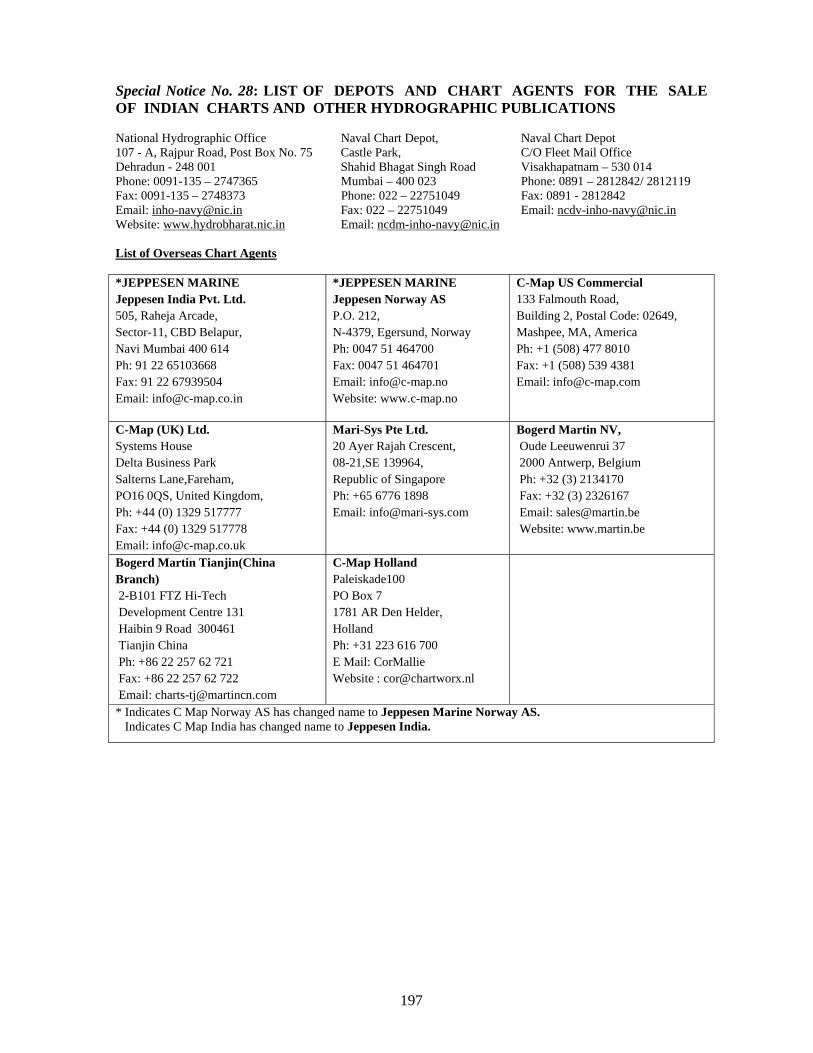
197
Special Notice No. 28: LIST OF DEPOTS AND CHART AGENTS FOR THE SALE OF INDIAN CHARTS AND OTHER HYDROGRAPHIC PUBLICATIONS
National Hydrographic Office Naval Chart Depot, Naval Chart Depot 107 - A, Rajpur Road, Post Box No. 75 Castle Park, C/O Fleet Mail Office Dehradun - 248 001 Shahid Bhagat Singh Road Visakhapatnam – 530 014 Phone: 0091-135 – 2747365 Mumbai – 400 023 Phone: 0891 – 2812842/ 2812119 Fax: 0091-135 – 2748373 Phone: 022 – 22751049 Fax: 0891 - 2812842 Email: [email protected] Fax: 022 – 22751049 Email: [email protected] Website: www.hydrobharat.nic.in Email: [email protected] List of Overseas Chart Agents *JEPPESEN MARINE Jeppesen India Pvt. Ltd. 505, Raheja Arcade, Sector-11, CBD Belapur, Navi Mumbai 400 614 Ph: 91 22 65103668 Fax: 91 22 67939504 Email: [email protected]
*JEPPESEN MARINE Jeppesen Norway AS P.O. 212, N-4379, Egersund, Norway Ph: 0047 51 464700 Fax: 0047 51 464701 Email: [email protected] Website: www.c-map.no
C-Map US Commercial 133 Falmouth Road, Building 2, Postal Code: 02649, Mashpee, MA, America Ph: +1 (508) 477 8010 Fax: +1 (508) 539 4381 Email: [email protected]
C-Map (UK) Ltd. Systems House Delta Business Park Salterns Lane,Fareham, PO16 0QS, United Kingdom, Ph: +44 (0) 1329 517777 Fax: +44 (0) 1329 517778 Email: [email protected]
Mari-Sys Pte Ltd. 20 Ayer Rajah Crescent, 08-21,SE 139964, Republic of Singapore Ph: +65 6776 1898 Email: [email protected]
Bogerd Martin NV, Oude Leeuwenrui 37 2000 Antwerp, Belgium Ph: +32 (3) 2134170 Fax: +32 (3) 2326167 Email: [email protected] Website: www.martin.be
Bogerd Martin Tianjin(China Branch) 2-B101 FTZ Hi-Tech Development Centre 131 Haibin 9 Road 300461 Tianjin China Ph: +86 22 257 62 721 Fax: +86 22 257 62 722 Email: [email protected]
C-Map Holland Paleiskade100 PO Box 7 1781 AR Den Helder, Holland Ph: +31 223 616 700 E Mail: CorMallie Website : [email protected]
* Indicates C Map Norway AS has changed name to Jeppesen Marine Norway AS. Indicates C Map India has changed name to Jeppesen India.

198
List of Indian Chart Agents. M/s OSA Books and Periodicals, R-246, Greater Kailash -I New Delhi - 110 048 Tel/Fax: 011-46557337, Mob: 9910891631, 9810705062 Email: [email protected]
M/s Sterling Book House, 181, Dr. DN Road Fort, Mumbai – 400 001 Tel: 91-22-22612521, Fax: 91-22-22623551 Email : [email protected]
M/s Global Charts & Nav. Aids Pvt. Limited 1A, Goa Mansion, Ground Floor 58, Dr. Sunderlal Bahl Path (Goa Street) Fort, Mumbai - 400 001 Tel: 91-22-22626318, 22626380, Fax: 91-22-22621488 Email: [email protected], [email protected]
M/s EW Stevens & Co. (Pvt.) Ltd. Mackinnon Mackenzie Bldg, Ground Floor, 4 Shoorji Vallabhdas Marg, Mumbai-400 038 Tel: 91-22-22618567, Fax: 022-22619146 Email: [email protected]
M/s C & C Marine Combine 25 Bank Street, 1st Floor, Mumbai - 400 023 Tel: 91-22- 22660525. 22661937, 22672143 Fax: 91-22-22670896 Email: [email protected]
M/s Maritime Charts & Publicatons 2/524 Sundeep Road, Chinna Neelangarai, Chennai 600041 Land Mark - Nearby Suganya Kalyana Mandapam Tele/Fax : +91-44-24490668 Mob No : +91-9003245348 Email: [email protected]
M/s SVR Chart Agencies Door No.50-81-35/6, Santhipuram, Seetammapeta, Visakhapatnam-530 016 Tele Fax: 0891-2799471, Cell: 9440132553, 9849120988, 9885308200 Email : [email protected]
M/s Jeppesen India Pvt. Ltd 505, Raheja Arcade, Sector 11 CBD, Belapur Navi Mumbai – 400 614 Tel: +91 22 5610 3668, Fax: +91 22 55939504 Mob: +9322238542 Email: [email protected], [email protected] Website: www.c-map.co.in
M/s JM Maritime Services 24/24C Kavarana Building Ground Floor, Wadi Bunder P.D Mello Road, Mumbai – 400 009 Tel: +91 22 23736756, Fax: 022 - 23725083 Cell: +91 9820788357 Email : [email protected], charts@ mtnl.net.in
M/S Inspire Shipping, 46a, Ashok Chamber, Broach Street, Masjid Bunder (E), Mumbai – 400 009 Fax : 022 – 27713146 Email : [email protected], [email protected]
M/S Lift-O-Marine Allens Mansion, Flat – C6 Nungli Station Road, Bata Nagar PO. Parbangla Kolkata - 700140 Tel: +91-33-24924293, Cell: +91-9477444392 Email: [email protected]
M/s Global Marine Infratech Pvt. Ltd. Siksha Sandan, Ground Floor, ND-7, VIP Area, IRC Village Bhubaneswar – 751015 Tel: +91-674-2550599, Fax: +91-674-2551899 Email: [email protected]; Website: www.gmiindia.in

199
Agent for Sale of ENC
The complete folios of Official Indian ENCs are distributed worldwide through JEPPESEN MARINE (formerly C-MAP), UKHO and Norwegian Hydrographic Service. UKHO distributes Indian ENCs through the world wide network of their agents and distributors. Updates are also made available as per the existing policy of the distributor. Mariners and other ENC users may contact the under mentioned for further details:- The Chief Hydrographer to the Government of India National Hydrographic Office 107-A, Rajpur Road Dehradun- 248001 Uttarakhand, India Tele: +91-135- 2747365, Fax: +91-135-2748373 Email: [email protected] [email protected] [email protected] Website: www.hydrobharat.nic.in
Director, M/s JEPPESEN Norway AS PO Box 212 N-4379 Egersund Norway Tel: +47-51- 464 700 Fax: +47-51-464 701 Mob : +91-9322 238 542 Email: [email protected], [email protected] Website: www.jeppesen.com
United Kingdom Hydrographic Office Admiralty Way, Taunton, Somerset TA1 2DN, UK Tel: +44 (0) 1823 337900 Fax: +44 (0) 1823 330561, 1823 284077 Telex: 46274 Email: [email protected] Web site: www.ukho.gov.uk
M/s Primar Norwegian Hydrographic Service, Postbox 60, 4001 Stavanger Telephone - +47 - 51 85 87 00 Fax - + 47 - 51 85 87 08 E-mail:[email protected] Website: - www.primar.org