IND780 Weighing Terminal Shared Data Reference · IND780 Weighing Terminal Essential Services for...
192
Shared Data Reference IND780 Weighing Terminal
Transcript of IND780 Weighing Terminal Shared Data Reference · IND780 Weighing Terminal Essential Services for...
Shar
ed D
ata
Refe
renc
e IND780 Weighing Terminal
IND780 Weighing Terminal
Essential Services for Dependable Performance of Your IND780 Weighing Terminal
Congratulations on choosing the quality and precision of METTLER TOLEDO. Proper use of your new equipment according to this Manual and regular calibration and maintenance by our factory-trained service team ensures dependable and accurate operation, protecting your investment. Contact us about a service agreement tailored to your needs and budget. Further information is available at www.mt.com/service.
There are several important ways to ensure you maximize the performance of your investment:
1. Register your product: We invite you to register your product at www.mt.com/productregistration so we can contact you about enhancements, updates and important notifications concerning your product.
2. Contact METTLER TOLEDO for service: The value of a measurement is proportional to its accuracy – an out of specification scale can diminish quality, reduce profits and increase liability. Timely service from METTLER TOLEDO will ensure accuracy and optimize uptime and equipment life.
a. Installation, Configuration, Integration and Training: Our service representatives are factory-trained, weighing equipment experts. We make certain that your weighing equipment is ready for production in a cost effective and timely fashion and that personnel are trained for success.
b. Initial Calibration Documentation: The installation environment and application requirements are unique for every industrial scale so performance must be tested and certified. Our calibration services and certificates document accuracy to ensure production quality and provide a quality system record of performance.
c. Periodic Calibration Maintenance: A Calibration Service Agreement provides on-going confidence in your weighing process and documentation of compliance with requirements. We offer a variety of service plans that are scheduled to meet your needs and designed to fit your budget.
© METTLER TOLEDO 2018
No part of this manual may be reproduced or transmitted in any form or by any means, electronic or mechanical, including photocopying and recording, for any purpose without the express written permission of METTLER TOLEDO.
U.S. Government Restricted Rights: This documentation is furnished with Restricted Rights.
Copyright 2018 METTLER TOLEDO. This documentation contains proprietary information of METTLER TOLEDO. It may not be copied in whole or in part without the express written consent of METTLER TOLEDO.
METTLER TOLEDO reserves the right to make refinements or changes to the product or manual without notice.
COPYRIGHT METTLER TOLEDO® is a registered trademark of Mettler-Toledo, LLC. All other brand or product names are trademarks or registered trademarks of their respective companies.
METTLER TOLEDO RESERVES THE RIGHT TO MAKE REFINEMENTS OR CHANGES WITHOUT NOTICE.
64059110 | 12 | 04/2018 METTLER TOLEDO IND780 Shared Data Reference 1
Contents 1 Introduction and Overview ............................................................ 1-1
1.1. IND780 Shared Data Design .......................................................... 1-1 1.1.1. Shared Data Access ............................................................................................. 1-1 1.1.2. Shared Data Design Concepts ............................................................................... 1-1
1.2. Shared Data Name Structure ........................................................... 1-2
1.3. Shared Data Storage Types ............................................................ 1-3 1.3.1. Dynamic Shared Data .......................................................................................... 1-3 1.3.2. Protected Process Shared Data ............................................................................. 1-3 1.3.3. Protected Setup Shared Data ................................................................................. 1-3 1.3.4. Protected Scale Calibration Shared Data ................................................................ 1-4
1.4. Shared Data Callbacks .................................................................. 1-4
1.5. Data Format Types ........................................................................ 1-5 1.5.1. Interpreting Attributes Tables ................................................................................. 1-5
1.6. Change History Log ....................................................................... 1-6
1.7. Shared Data Access Control ........................................................... 1-6
1.8. Validating Setup Data .................................................................... 1-7
1.9. Shared Data Server Commands ...................................................... 1-7 1.9.1. user ................................................................................................................... 1-8 1.9.2. pass .................................................................................................................. 1-8 1.9.3. help ................................................................................................................... 1-8 1.9.4. quit .................................................................................................................... 1-8 1.9.5. UNICODE ............................................................................................................ 1-8 1.9.6. read ................................................................................................................... 1-9 1.9.7. write .................................................................................................................. 1-9 1.9.8. system ............................................................................................................... 1-9 1.9.9. systat ............................................................................................................... 1-10 1.9.10. noop ................................................................................................................ 1-10 1.9.11. callback ........................................................................................................... 1-10 1.9.12. xcallback .......................................................................................................... 1-11 1.9.13. group ............................................................................................................... 1-11 1.9.14. rgroup .............................................................................................................. 1-11 1.9.15. xgroup ............................................................................................................. 1-12 1.9.16. contout ............................................................................................................. 1-12 1.9.17. xcontout ........................................................................................................... 1-12 1.9.18. printout 1 ......................................................................................................... 1-12 1.9.19. xprintout ........................................................................................................... 1-13 1.9.20. ctimer .............................................................................................................. 1-13 1.9.21. csave ............................................................................................................... 1-13 1.9.22. cload ............................................................................................................... 1-13
1.10. Interactive Remote Standard Database Access ................................ 1-14 1.10.1. CREATETABLES ................................................................................................. 1-14

2 METTLER TOLEDO IND780 Shared Data Reference 64059110 | 12 | 04/2018
Cont
ents
1.10.2. OPENTABLES .................................................................................................... 1-15 1.10.3. CLOSETABLES ................................................................................................... 1-15 1.10.4. SETROW ........................................................................................................... 1-15 1.10.5. SELECTROW ..................................................................................................... 1-16 1.10.6. NEXTROW ........................................................................................................ 1-17 1.10.7. SETITEM ........................................................................................................... 1-17 1.10.8. DELROW .......................................................................................................... 1-18 1.10.9. DELTABLE ......................................................................................................... 1-18 1.10.10. BEGINTRANS..................................................................................................... 1-18 1.10.11. ENDTRANS ....................................................................................................... 1-19 1.10.12. TRANSTIME ....................................................................................................... 1-19 1.10.13. SELECTSET ....................................................................................................... 1-19 1.10.14. SQLTABLE ......................................................................................................... 1-20
1.11. Concurrent Access to Standard Databases ...................................... 1-20 1.11.1. CREATETABLES ................................................................................................. 1-20 1.11.2. OPENTABLES .................................................................................................... 1-20 1.11.3. CLOSETABLES ................................................................................................... 1-20 1.11.4. SETROW ........................................................................................................... 1-21 1.11.5. SELECTROW, SELECTID, and NEXTROW .............................................................. 1-21 1.11.6. SETITEM and SETID ........................................................................................... 1-21 1.11.7. DELROW and DELID .......................................................................................... 1-21 1.11.8. BEGINTRANS..................................................................................................... 1-21 1.11.9. ENDTRANS ....................................................................................................... 1-21 1.11.10. TRANSTIME ....................................................................................................... 1-21
2 Scale Data .................................................................................. 2-1
2.1. Scale Functionality ........................................................................ 2-1 2.1.1. Dynamic Scale Weight (WT) ................................................................................ 2-1 2.1.2. Scale Process Data (WS) ..................................................................................... 2-3 2.1.3. Scale Commands (WC) ....................................................................................... 2-5 2.1.4. Scale Statuses (WX) ............................................................................................ 2-7 2.1.5. Working Scale Setup Data (WK) ......................................................................... 2-10 2.1.6. Scale Setup (CS) ............................................................................................... 2-12 2.1.7. Scale Tare Setup (CT) ........................................................................................ 2-18 2.1.8. Scale Zero Setup (ZR) ........................................................................................ 2-20 2.1.9. Scale Totalization Process Data (TZ) ................................................................... 2-22 2.1.10. Totalization Setup (TS) ....................................................................................... 2-23 2.1.11. System Process Data (XT) .................................................................................. 2-24
2.2. Calibration and Monitoring ........................................................... 2-25 2.2.1. Calibration Parameters (QP) ............................................................................... 2-25 2.2.2. Cell Calibration (CC) .......................................................................................... 2-26 2.2.3. Scale Calibration (CE) ....................................................................................... 2-27 2.2.4. Cell Shift Adjust (CX) ......................................................................................... 2-33 2.2.5. POWERCELL Network Dynamic Data (PW) .......................................................... 2-34 2.2.6. POWERCELL Monitoring Process Data (PC) ......................................................... 2-35 2.2.7. Scale Monitoring & Service Data (WM) ................................................................ 2-35
64059110 | 12 | 04/2018 METTLER TOLEDO IND780 Shared Data Reference 3
2.2.8. Scale Monitoring Setup (CM) .............................................................................. 2-38 2.2.9. PDX Cell Dynamic Shared Data (PY) ................................................................... 2-41 2.2.10. PDX Cell Setup Table (PX) .................................................................................. 2-42 2.2.11. PDX Scale 1 Cell Calibration Table (P1) .............................................................. 2-43 2.2.12. PDX Scale 2 Cell Calibration Table (P2) .............................................................. 2-44 2.2.13. PDX Scale 3 Cell Calibration Table (P3) .............................................................. 2-44 2.2.14. PDX Scale 4 Cell Calibration Table (P4) .............................................................. 2-44 2.2.15. PDX Cell Diagnostic Monitoring Table (MX) .......................................................... 2-45 2.2.16. PDX Cell Identification Information (DX) ............................................................... 2-46 2.2.17. PDX Cell Monitoring Process Data (PM) .............................................................. 2-46 2.2.18. PDX Cell Layout Mapping ................................................................................... 2-47
3 Flow Meter Data .......................................................................... 3-1 3.1.1. Dynamic Flow Meter Weight (FW) ......................................................................... 3-1 3.1.2. Flow Meter Commands (FX) ................................................................................. 3-3 3.1.3. Flow Meter Setup (FS) .......................................................................................... 3-4 3.1.4. Flow Meter Process Data (FP) .............................................................................. 3-6
4 Application Data .......................................................................... 4-1 4.1.1. Application Dynamic Commands and Events (AC) .................................................. 4-1 4.1.2. Application Dynamic Statuses (AS) ....................................................................... 4-1 4.1.3. Application Dynamic Integer Fields (AI).................................................................. 4-2 4.1.4. Application Dynamic Floating Point Fields (AJ) ....................................................... 4-2 4.1.5. Application Dynamic Unicode String Fields (AK) ..................................................... 4-3 4.1.6. Application Dynamic Character Arrays (AL) ............................................................ 4-3 4.1.7. Application Floating Point Process Data (AF) .......................................................... 4-4 4.1.8. Application Integer Process Data (AP) ................................................................... 4-4 4.1.9. Application Unicode String Process Data (AR) ........................................................ 4-4 4.1.10. Application Installation Information (AQ) ................................................................ 4-5 4.1.11. Application Message Table (AW) .......................................................................... 4-6 4.1.12. Application Integer Setup (AX) ............................................................................... 4-6 4.1.13. Application Floating Point Setup (AY)..................................................................... 4-6 4.1.14. Application Unicode String Field Setup (AZ) ............................................................ 4-7 4.1.15. TaskExpert Application Start and Stop Triggers (AT) ................................................. 4-7 4.1.16. TaskExpert Data Entry Unicode String Fields (TX) .................................................... 4-8
5 Target Data ................................................................................. 5-1
5.1. Complex Target Data ..................................................................... 5-1 5.1.1. Full Target Commands (SC) ................................................................................. 5-1 5.1.2. Full Target Statuses (ST) ...................................................................................... 5-2 5.1.3. Full Target Process Data (SP) ............................................................................... 5-3
5.2. Simple Target Data ...................................................................... 5-11 5.2.1. Simple Target Commands (SK) ........................................................................... 5-11 5.2.2. Simple Target Statuses (SS) ............................................................................... 5-12 5.2.3. Simple Target Process Data (SD) ........................................................................ 5-12 5.2.4. Auto-Jog Target Process Data (SJ)...................................................................... 5-15
4 METTLER TOLEDO IND780 Shared Data Reference 64059110 | 12 | 04/2018
Cont
ents
6 Discrete I/O Data ......................................................................... 6-1 6.1.1. Discrete Input/Output Status (DI) ........................................................................... 6-1 6.1.2. Discrete Input Edges (DE) .................................................................................... 6-2 6.1.3. Remote Discrete Input Edges (RE) ......................................................................... 6-2 6.1.4. Remote Discrete Input/Output Status (RI) ............................................................... 6-3 6.1.5. Internal Ladder Logic Program Setup (LL) .............................................................. 6-4
7 Database and Table Data .............................................................. 7-1
7.1. General Information ....................................................................... 7-1
7.2. Table Column Definition ................................................................. 7-1
7.3. Table Shared Data Blocks .............................................................. 7-1 7.3.1. Database Table Description (DD) .......................................................................... 7-1 7.3.2. Database Table Setup (DS) .................................................................................. 7-5 7.3.3. Temporary Database Table Description (TD) .......................................................... 7-7
8 Communication and PLC Data ...................................................... 8-1
8.1. Web and Network Data .................................................................. 8-1 8.1.1. Dynamic System Console Data (XW) .................................................................... 8-1 8.1.2. Web Page Process Data (HT) ............................................................................... 8-2 8.1.3. Network Node Status (NS) .................................................................................... 8-2 8.1.4. Cluster IP Addresses (NC) .................................................................................... 8-3 8.1.5. Network Print Client Setup (NP) ............................................................................ 8-4 8.1.6. Data Connections Setup (DC) ............................................................................... 8-5 8.1.7. Email Alert Setup (NA) ......................................................................................... 8-8 8.1.8. FTP Server Setup (NF) .......................................................................................... 8-9 8.1.9. Network Print Client Setup (NK) .......................................................................... 8-10 8.1.10. TCP/IP/Ethernet Network Setup (NT) .................................................................... 8-11 8.1.11. Serial Port Setup (RP) ........................................................................................ 8-11
8.2. Print and Templates Data ............................................................. 8-12 8.2.1. Demand Print Setup (DP) ................................................................................... 8-12 8.2.2. Custom Print Commands & Statuses (CP) ........................................................... 8-14 8.2.3. Print Templates Setup (PT) ................................................................................. 8-14 8.2.4. Report Print Templates Setup (RT) ....................................................................... 8-15
8.3. PLC Data ................................................................................... 8-16 8.3.1. PLC Setup (PL) ................................................................................................. 8-16 8.3.2. Dynamic PLC IO Data (PD) ................................................................................ 8-19 8.3.3. PLC Network Data (PN) ..................................................................................... 8-21 8.3.4. PLC Bridge Process Data (PB) ............................................................................ 8-21 8.3.5. Cyclic Output-to-PLC Assembly Template Setup (PO) ............................................ 8-22 8.3.6. Cyclic Input-From-PLC Assembly Template Setup (PI) ........................................... 8-23 8.3.7. Analog Output Setup (AO) .................................................................................. 8-24
8.4. Barcode Data ............................................................................. 8-26 8.4.1. Barcode Input Message (MB) ............................................................................. 8-26 8.4.2. Barcode Input Templates Setup (BT).................................................................... 8-26
64059110 | 12 | 04/2018 METTLER TOLEDO IND780 Shared Data Reference 5
9 Other Data ................................................................................... 9-1
9.1. Display and Keyboard Data ............................................................ 9-1 9.1.1. Power-Up Weight Display (XA) ............................................................................. 9-1 9.1.2. Dynamic Weight Display Commands (XB) ............................................................. 9-2 9.1.3. Dynamic Display Positions (XY) ........................................................................... 9-4 9.1.4. Static Home SoftKey Page (KH) ............................................................................ 9-5 9.1.5. Dynamic SoftKey Page Stack (KP) ........................................................................ 9-6
9.2. System Status and Setup Data ........................................................ 9-8 9.2.1. System State (XD) ............................................................................................... 9-8 9.2.2. System Logs Setup Data (XR) ............................................................................. 9-13 9.2.3. System Log Process Data (XM) .......................................................................... 9-15 9.2.4. Transaction Number Setup (XN) .......................................................................... 9-16 9.2.5. System Setup (XS) ............................................................................................ 9-17 9.2.6. System Commands (XK) .................................................................................... 9-20 9.2.7. System Monitoring & Service Data (XP) ............................................................... 9-23 9.2.8. Setup Sequencing Control (QC) ........................................................................... 9-25 9.2.9. Board Identifications (BD) .................................................................................. 9-32 9.2.10. Option Board ID & Calibration EEPROM (BC) ....................................................... 9-33 9.2.11. System Feature Triggers & Controls (XC) .............................................................. 9-34
9.3. ID Sequence Data ....................................................................... 9-36 9.3.1. Prompt Setup (PR) ............................................................................................ 9-36 9.3.2. Prompt Response (PA) ...................................................................................... 9-38
9.4. Users and Security Data ............................................................... 9-38 9.4.1. Logged-In Users (XL) ......................................................................................... 9-38 9.4.2. Access Security Setup (XU) ................................................................................. 9-38 9.4.3. Application Virtual Console Messages (AM) ......................................................... 9-39 9.4.4. Keyboard Routing Commands (KC) .................................................................... 9-40
A Revision History .......................................................................... A-1
A.1. Software and Document Revisions .................................................. A-1
64059110 | 12 | 04/2018 METTLER TOLEDO IND780 Shared Data Reference 1-1
This chapter covers
• Shared Data Design
• Shared Data Name Structure
• Shared Data Callbacks
• Data Format Types
• Change History Log
• Shared Data Access Control
• Validating Setup Data
• Shared Data Server Commands
• Interactive Remote Standard Database Access
• Concurrent Access to Shared Databases
1 Introduction and Overview The Shared Data (SD) Object is the central repository for all “system” data in the IND780. It is also the primary interface for sending commands and exchanging data between local or remote Applications and the IND780.
1.1. IND780 Shared Data Design The Shared Data concept is a very powerful and flexible tool that provides mechanisms both for storing system data and for providing interfaces among Local Applications, Remote Applications, and the Resident Scale Task.
1.1.1. Shared Data Access
All setup parameters, triggers and statuses in the IND780 are stored and routed through Shared Data. This system of memory mapping permits remote clients to send commands and receive data from the terminal. In order to access the shared data variables in the IND780, a remote client must login to the Shared Data Server. Access is provided through the Ethernet port.
The shared data server is available via port 1701. For applications that have no access to port 1701, a second port can be enabled. To enable the second port, enter the desired port number in setup at Communication > Network > Port. Regardless of the method used, the same access is provided and the login procedure is very similar.
1.1.2. Shared Data Design Concepts
The following are some important Shared Data design concepts: • Shared Data provides Local and Remote Applications very fast access to the permanently
stored data. Shared Data access time is less than 350 microseconds.
• Local and Remote Applications access a Shared Data field using a six-character UNICODE name. Names provide consistency to Applications in accessing Shared Data fields in successive versions of Shared Data. The names for existing fields will remain the same even
1-2 METTLER TOLEDO IND780 Shared Data Reference 64059110 | 12 | 04/2018
Intro
duct
ion
and
Ove
rvie
w
when new fields are added or when new physical storage locations are assigned to existing data.
• Shared Data supports “callbacks” that alert a task when a Shared Data field is updated or changes. An application can “Register a Callback Routine” for a particular Shared Data field. Then, when a task writes a new value to a Shared Data field that has a registered callback, Shared Data calls the registered callback routine.
• Shared Data supports both “native” and “string representation” access to data fields. However, Shared Data always stores the data fields in their native format. When an Application accesses a Shared Data field in its native data format, such as binary floating point or integer number representations, Shared Data simply copies the data between its storage and the application interface. When Applications access the Shared Data using a string data format, Shared Data automatically makes the data conversion between the native and the string data format.
• Shared Data provides access to an entire Shared Data block with a single read or write command. Applications can access the block of data in either native format or string format. When the application accesses the data in native format, Shared Data returns a “C-style structure” that matches the native format of the data. When the application accesses the data in string format, Shared Data converts each individual field to its string format, separating fields with a caret (‘^’).
• Shared Data provides access to a list of Shared Data fields. Applications can read a list of fields in either native format or string format. If the application accesses the data in native format, Shared Data returns a “C structure” that matches the native format of the data. If the application accesses the data in string format, Shared Data converts each individual field to its string format, separating each field with a caret (‘^’).
• Shared Data provides a checksum on each protected Shared Data field. It verifies the checksum on power-up and on each read access. It recalculates and stores the new checksum on each write access. When Shared Data detects a checksum failure, it reports a system failure.
1.2. Shared Data Name Structure Each Shared Data name contains three pieces of information -- the shared data class (group), instance and attribute (item). For example, sp0106 is constructed as follows:
sp = Class = Full Target Process Data
01 = Instance = Scale #1
06 = Attribute = Target Latching Type
In the following sections, multiple Instances are indicated with dashes (--) in place of the Instance number – e.g. sp--06.
64059110 | 12 | 04/2018 METTLER TOLEDO IND780 Shared Data Reference 1-3
1.3. Shared Data Storage Types There are four types of IND780 Shared Data. The letters below are used throughout this document to identify the type of each variable:
D Dynamic (Dynamic RAM) Shared Data
PP Protected Process (BRAM) Shared Data
PS Protected Setup (FLASH) Shared Data
PC Protected Scale Calibration (EEPROM) Shared Data
1.3.1. Dynamic Shared Data
Dynamic Shared Data is process data that is created dynamically within the IND780. The terminal writes and reads these fields very frequently. The IND780 does not save this Shared Data across a power-failure, but re-initializes it to zero at power-up. The best example of Dynamic Shared Data is the Dynamic Scale Weight data (WT).
1.3.2. Protected Process Shared Data
Protected Process Shared Data is persistent data that may be written and read many times. However, in case of a power-failure the IND780 must save the data so the process can continue after power-up. The terminal writes this Shared Data to battery-backed RAM (BRAM) to save it across a power failure. An example of Protected Process Shared Data is the state of a Material Transfer process, where you cannot afford to throw out an incomplete batch of material after a power-failure. The IND780 must save its state so the Material Transfer can continue after a power-up.
Writing BRAM Shared Data During Power-Down
A critical event occurs when the IND780 attempts to write to BRAM Shared Data just as the power goes down. The IND780 writes part of a Shared Data field successfully, and then power drops below a valid-power threshold before the IND780 can complete the write, causing a corrupted BRAM. Since writes to BRAM can occur frequently in a process control environment, it is probable that this will happen at some point when the terminal is running.
To protect against this potential problem, the IND780 does a two-stage write procedure whenever it writes to BRAM:
• The terminal first writes a write-in-progress flag, the new Shared Data field, its SD field index, and its checksum to a temporary location in BRAM. When this write is successfully completed, the IND780 then writes the SD field and its checksum to its actual location in BRAM. When this write is successfully completed, the terminal clears the write-in-progress flag.
• At power-up, the IND780 checks the write-in-progress flag. If it is set, the IND780 writes the original SD field from the temporary field and clears the write-in-progress field.
1.3.3. Protected Setup Shared Data
Protected Setup Shared Data is the persistent data that stores the unique configuration of the IND780. The IND780 Setup Procedure typically writes this data once during the Setup procedure and then never writes it again. Other processes may read it many times. The IND780 writes this Shared Data to Flash Memory to save it permanently across a power-failure.
Writing Flash Shared Data During Power-Down
A critical window occurs when the IND780 attempts to write to Flash Shared Data just as the power goes down, causing corrupted Flash Shared Data. The IND780 writes part of a Shared Data field
1-4 METTLER TOLEDO IND780 Shared Data Reference 64059110 | 12 | 04/2018
Intro
duct
ion
and
Ove
rvie
w
successfully, and then power drops below a valid-power threshold before the IND780 can complete the write.
The IND780 writes to FLASH Shared Data using the Windows CE O/S FLASH File System. It is a multi-stage operation involving many writes to Flash to update the file system directory as well as the file. Writing to the Flash itself is relatively slow.
To reduce the likelihood of this corruption, the IND780 only writes to the Flash during Setup. The IND780 never writes to Flash Shared Data during normal operation. The time the IND780 spends in Setup is extremely small when compared to the time it spends in normal operation. Typically, the service technician sets up the IND780 once and never accesses Setup again.
To protect against the potential corruption problem, the IND780 does a multi-stage write procedure whenever it writes to FLASH:
• When the IND780 first writes the new Shared Data field data, it writes the SD field index and sets a write-in-progress flag to temporary locations in BRAM.
• After successfully completing this write, the IND780 then writes the SD field to its actual location in FLASH, in the FLASH.bin file.
• It records the change in the change history log file.
• After successfully completing the write to flash, the IND780 clears the write-in-progress flag. Upon exiting setup, the IND780 creates a backup copy of the FLASH.bin file.
• At power-up, the IND780 reads the FLASH.bin file into memory. If this fails, the IND780 checks for the presence of a FLASH backup file. If it exists, it copies the flash backup and restores any additional entries from the change history log file. The IND780 then checks the write-in-progress flag. If it is set, the IND780 writes the original SD field from the temporary field and clears the write-in-progress flag.
1.3.4. Protected Scale Calibration Shared Data
Protected Scale Calibration Data is the persistent scale calibration data. The IND780 writes this Shared Data to the EEPROM on the Scale boards to protect it across a power-failure. On power-up, it reads an image of the EEPROM into the Protected Process BRAM Shared Data. The IND780 only writes the EEPROM after a successful scale calibration.
Writing EEPROM Shared Data During Power-Down
A critical event occurs when the IND780 attempts to write to EEPROM Shared Data just as the power goes down. The IND780 writes part of the EEPROM successfully, and then power drops below a valid-power threshold before the IND780 can complete the write, causing a corrupted EEPROM.
To protect against this potential problem, the IND780 does a two-stage write procedure whenever it writes to EEPROM:
• The IND780 first writes a write-in-progress flag and the new EEPROM data into a temporary location in BRAM. When this write is successfully completed, the IND780 then writes the data and its checksum to the EEPROM. When this second write is successfully completed, the IND780 clears the write-in-progress flag.
• At power-up, the IND780 checks the write-in-progress flag. If it is set, the IND780 writes the EEPROM from the temporary field and clears the write-in-progress field.
1.4. Shared Data Callbacks The client application can request callbacks on lists of Shared Data fields so that the Shared Data Server calls back the client when the data is updated or changes. The application does not have to repeatedly poll for new data, but the Shared Data Server alerts the application when the data is updated or changes by sending a message with the value of the new data.
64059110 | 12 | 04/2018 METTLER TOLEDO IND780 Shared Data Reference 1-5
The IND780 designates the special Shared Data fields that can use callbacks as “real-time” fields. In this document, “rt” designates real-time fields, while “na” designates non-real-time fields that do NOT support callbacks. Edge-Sensitive commands are also real-time fields, but the IND780 only makes a callback to process these commands when the field transitions from zero to a non-zero value. In this document, “rc” designates edge sensitive command fields.
na Callback not supported
rt Callback supported
rc Callback on edge sensitive fields
Certain dynamic SDVs (eg. wt--, wx--, etc) are updated continuously and will generate a callback message periodically even though the value of the variable is unchanged.
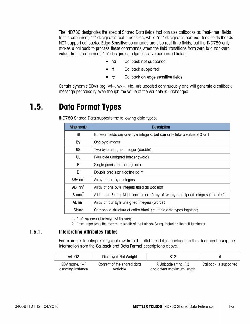
1.5. Data Format Types IND780 Shared Data supports the following data types:
Mnemonic Description
Bl Boolean fields are one-byte integers, but can only take a value of 0 or 1
By One byte integer
US Two byte unsigned integer (double)
UL Four byte unsigned integer (word)
F Single precision floating point
D Double precision floating point
ABy nn1 Array of one byte integers
ABl nn1 Array of one byte integers used as Boolean
S mm2 A Unicode String. NULL terminated. Array of two byte unsigned integers (doubles)
AL nn1 Array of four byte unsigned integers (words)
Struct Composite structure of entire block (multiple data types together)
1. “nn” represents the length of the array
2. “mm” represents the maximum length of the Unicode String, including the null terminator.
1.5.1. Interpreting Attributes Tables
For example, to interpret a typical row from the attributes tables included in this document using the information from the Callback and Data Format descriptions above:
wt--02 Displayed Net Weight S13 rt
SDV name, “--” denoting instance
Content of the shared data variable
A Unicode string, 13 characters maximum length
Callback is supported
1-6 METTLER TOLEDO IND780 Shared Data Reference 64059110 | 12 | 04/2018
Intro
duct
ion
and
Ove
rvie
w
1.6. Change History Log The IND780 maintains a history of all changes to the Setup and Calibration Shared Data in a resident Flash Memory file. There is a separate record for each changed field. The record contains the field name, date and time, user ID, and the new contents of the field. It also maintains a history log of all Shared Data backups and restores. The Change History file serves the following purposes:
• It provides traceability of changes to Setup and Calibration data. It allows the customer or service technician to find and view the changes to Shared Data. They can validate that the system has been setup properly and that Shared Data contains only the authorized settings.
• It satisfies the FDA CFR 21 Part 11 regulations for the U.S. food and pharmaceutical industries for maintaining strict control over the safety of their processes and for documenting any changes to their processes.
• In case of a catastrophic system failure, you can use an archived Change History file to reconstruct Shared Data. To recover the system, you must first reset the system to the factory defaults and then use a utility to apply the changes from the Change History file one at a time.
The Unicode format of each history record is: “SSSSSS DDDDDD TTTTTT AUTHOR L VALUE”
Where:
• SSSSSS is the six-letter Shared Data Name;
• DDDDDD is the date of change from xd0103;
• TTTTTT is the time of change from xd0104;
• AUTHOR is the name of the user who made the change from xd0125, xd0127, or xd0129;
• L is the security-level of the user who made the change from xd0126, xd0128, or xd0130;
• VALUE is a Unicode representation of the new value written to the Shared Data variable.
The Change History is a maximum of 250,000 bytes long. When the file is 75% full, the IND780 SD issues a warning to the user that the file is becoming full. Then, the user can offload it to a PC using FTP and reset the resident log file. When the file becomes 90% full, the IND780 SD issues a severe warning to the user. Again, the user can ffload the log file to a PC and reset the resident log file. When the file becomes 100% full, the IND780 SD issues an “error alert“ to the operator and halts any further updates to Setup until the user takes the appropriate action to save and reset the resident log file.
1.7. Shared Data Access Control Generally, anyone can read any Shared Data field. The notable exceptions are password fields, which only the IND780 system may read. Hard-coding in Shared Data restricts read-access to the password fields. The user access level for the shared data server connection must match (or exceed) the level expected for the shared data field (currently assigned based on block type) to permit a shared data write. There are four classes of user – Administrator, Maintenance, Supervisor, and Operator. The Administrator class always has the maximum possible write-access capability. However, not even an Administrator can write into “Read Only” fields. Typical “Read Only” fields are real-time data fields that contain the weight data for the scale.
64059110 | 12 | 04/2018 METTLER TOLEDO IND780 Shared Data Reference 1-7
To satisfy legal metrology regulations or customers’ security concerns, it is often necessary to limit terminal write-access after the customer has installed the terminal. For example, no user of any class may change metrological setup parameters after a government inspector has certified and sealed the terminal. The IND780 has a Security Switch on its main PCB. The service technician can mechanically seal the IND780 to prevent tampering with the Security Switch. When in the UNSECURED position, authorized users may write to Shared Data fields according to the “access privilege”. In the SECURED position, NO users have write-access to Shared Data fields that previously had Administrator-only level, write privileges.
1.8. Validating Setup Data IND780 Shared Data validates changes to Protected Setup and Calibration EEPROM fields. It compares the new value with the range of legal values stored in the Shared Data Dictionary. If Shared Data finds the new value is not legal, it does not update the field and returns an error status to the application. Shared Data does not validate all fields. It only validates those that it can validate using a table of values. It does not validate fields that require special programming logic to validate. Shared Data supports an application command that returns the validation criteria for a particular field to the application so the application can display the list of legal values. The Shared Data Dictionary has different validation criteria based on the type of validation required. Some of the validation types include:
• Boolean validation. Only zero or one are legal values.
• Range validation. Only values within a range are valid. The Data Dictionary contains the minimum and maximum legal values. For example, integer values from one to five are valid, or floating-point values from 0.0 to 9.9 are valid.
• List validation. Only values in a list of values are valid. For example, values ‘N’, ‘S’, ‘M’, and ‘H’ are valid.
• No validation.
1.9. Shared Data Server Commands After connecting to the Shared Data Server in the IND780, several commands are available for use by the client. All commands can be given in either upper- or lower-case letters. The quotation marks shown are for clarity only and should not be transmitted. Valid commands are described in the following sections.
Response Format: “Read”, “write”, and “callback” message responses have a formatted header. The first two characters indicate the status. “00” is the success status. “99” is a failure status. The next character is the type of message, “R”, “W”, or “C”. The next three characters are a sequence number, which cycles from 001 to 999, and then starts over again.
If the command sent to the IND780 has a syntax error or is invalid, the terminal will respond with: 81 Parameter Syntax Error or 83 Command Not Recognized.
1-8 METTLER TOLEDO IND780 Shared Data Reference 64059110 | 12 | 04/2018
Intro
duct
ion
and
Ove
rvie
w
1.9.1. user
A client must login to the SDSV using the “user” command before accessing Shared Data. The server validates the username and sends a response message back to the user. The SDSV responds with [Access OK] if no password is required or [Enter password] if a password is required.
A client can use only the “user”, “pass”, “help” and “quit” commands before successfully logging on.
Format: user username
Response 1: 12 Access OK
Response 2: 51 Enter Password
1.9.2. pass
The user enters a password using the “pass” command. If the password is valid, the server displays the [Access OK] message. If not valid, the server displays the [No access] message.
Format: pass password
Response: 12 Access OK
1.9.3. help
The “help” command returns the list of the valid commands for the IND780.
Format: help
Response: 02 USER PASS QUIT READ R WRITE W SYSTEM CALLBACK XCALLBACK GROUP RGROUP XGROUP CTIMER LOAD SAVE HELP NOOP CONTOUT XCOUNTOUT PRINTOUT XPRINTOUT
1.9.4. quit
The “quit” command terminates the TCP/IP connection.
Format: quit
Response: 52 Closing connection
1.9.5. UNICODE
The UNICODE command enables the communications messages between the client and server to use Unicode data encoding. The default message format uses ASCII data encoding. The response is in ASCII data encoding, but the next command must be in unicode.
Format: UNICODE
Response: 00U ~ OK
64059110 | 12 | 04/2018 METTLER TOLEDO IND780 Shared Data Reference 1-9
1.9.6. read
The “read” command allows the client to read a list of one or more Shared Data fields. An individual field or an entire block can be read. If more than one field is requested, the fields should be separated by a space. If successful, the server responds with a separated list of values in ASCII format. The server separates individually requested fields with a “~”; and Shared Data separates items within a block with a ”^”. If an error is detected, the server responds with an error message. The maximum length of the reply message is 1,024 characters.
Format: read SDV#1 SDV#2
Example 1: read wt0101 wt0103
Response 1: 00R003~ 17.08~lb~
Example 2: read sp0100 (reads entire block)
Response 2: 00R012~XP/0163M^1^^78^20.500000^0^0^0^1.200000^3.500000^0.150000^0.050000^0^0.000000^0.000000^0^0^0^0^0^0^1^0.000000^0.000000^0.000000^0.000000^0.000000^~
The “read” command can be abbreviated to the letter “r” if desired.
1.9.7. write
The “write” command allows the client to write a list of one or more Shared Data fields. A single field or an entire block can be written. The maximum length of the write message is 1,024 characters. Items within a list of writes must be separated with a “~”. You must separate items within a block with a “^”.
Format: write SDVblock#1 = value1^value2^ value3 write SDV#1 = value1~SDV#2 = value2~SDV#3 = value3
Example1: write ak0100 = abc^def^hij^lmn (writes fields into a block)
Response 2: 00W006~OK
Example 2: write aj0101 = 12.56~aj0150 = 987.653 (writes fields within a list)
Response 2: 00W007~OK
The “write” command can be abbreviated to the letter “w” if desired.
1.9.8. system
The “system” command returns a description of the IND780 terminal. This is the same information that is shown on the Recall System Information screen of the IND780.
Format: system
Response: 00S001~IND780 SYSTEM INFO RECALL
Model: IND780
1-10 METTLER TOLEDO IND780 Shared Data Reference 64059110 | 12 | 04/2018
Intro
duct
ion
and
Ove
rvie
w
S/N: ID1: IND780 ID2: Mettler Toledo ID3:
Hardware HMI Mono POWERCELL Analog Load Cell Serial IO Discrete IO 780VETE (Pac)
Software IND780 RST: 5.1 IND780 CP: 5.1 VehiclePack.cpt: 5.1
1.9.9. systat
The “systat” command returns a description of the IND780 terminal’s resource utilization such as the CPU load and memory use.
Format: systat
Response: 00S001~IND780, D173678R.0, WinCE 4.20,
TotalMemory = 24576 KB FreeMemory = 7888 KB MemoryLoad = 68
TotalStore = 24504 KB FreeStore = 24258 KB CPU Load = 25
1.9.10. noop
The “noop” command performs no task; it checks communication and returns an [OK] response message.
Format: noop
Response: 00OK
1.9.11. callback
The “callback” command allows the client to define one or more fields for which the Shared Data Server sends a message to the client when the value of the callback field is updated or changes. Only certain SDV may be included in a callback command. These SDV are noted by an “rc” or “rt” status in the column after the structure column in the Shared Data document. Mainly, these are triggers that are used in the terminal. SDV with a status of “na” are not real-time SDV and cannot be used in callbacks. Certain dynamic SDV (eg. wt--, wx--, etc) is updated continuously and will generate a callback message periodically eventhough the value of the variable is unchanged.
The callback message contains one or more changed field names and the new value for each field. A maximum of twelve callback fields can be specified. The “ctimer” command specifies the minimum time between repeated callback messages.
64059110 | 12 | 04/2018 METTLER TOLEDO IND780 Shared Data Reference 1-11
Format: callback SDV#1 SDV#2
Example: callback st0102 st0103 st0104
Response 1: 00B001~OK
Response 2: 00C005~st0102 = 0^st0103 = 1^st0104 = 1 (sent when all of the SDV change)
Response 3: 00C006~st0104 = 0 (sent when only st0104 changes)
1.9.12. xcallback
The “xcallback” command allows the client to remove one or more callback fields from the list of current SDV.
Format: xcallback SDV#1 SDV#2 or xcallback all (removes all callbacks)
Example: xcallback st0102 (removes st0102 SDV from callback)
Response: 00X008~OK
1.9.13. group
The “group” command allows the client to define a group of callback fields. The Shared Data Server sends a message to the client when the value of any field in the group changes. The group callback message contains the group number and the values of all fields in the group in the defined order. The “ctimer” command specifies the minimum time between repeated callback messages. The maximum number of groups is six, and the maximum number of fields in a group is twelve.
Format: group n SDV#1 SDV#2 SDV#3 (where n = the number of the group 1–6)
Example: group 5 st0103 st0104 st0107 (groups target feeding and tolerance SDV into one group)
Response 1: 00B019~OK
Response 2: 00C026~group5 = 0^1^0 (indicates status of all 3 SDV in group 5 whenever any one of them changes)
1.9.14. rgroup
The “rgroup” command allows the client to define a group of fields. The client can use the group number to read the entire group at once using the READ command. The maximum number of groups is six, and the maximum number of fields in a group is twelve.
Format: rgroup n SDV#1 SDV#2 (where n = the number of the group 1–6)
Example: rgroup 3 di0101 di0102 di0103 di0104 (groups all discrete inputs into one group that can be read with a single read command)
Response: 0G008~group = 3, number fields = 4
Read Example: r 3
1-12 METTLER TOLEDO IND780 Shared Data Reference 64059110 | 12 | 04/2018
Intro
duct
ion
and
Ove
rvie
w
Response: 00R009~1~0~1~0~
1.9.15. xgroup
The “xgroup” command allows the client to remove one or all groups.
Format: xgroup n (where n = the group number 1 - 6) or XGROUP all (removes all groups, including “contout” and “printout”)
Example: xgroup 5 (cancels group 5)
Response: 00X011~group = 5
1.9.16. contout
The “contout” command allows the client to define the Continuous Output message streams from scales as a group of one or more “callback” fields. The Console Print Server sends a group message to the client at each continuous output. The Continuous Output message is either in the Standard Mettler Toledo Continuous Output format, in the Extended Mettler Toledo Continuous Output format, in Multiplexed Mettler Toledo Continuous Output format, or in a custom template format. The “Data Connections” block in Shared Data defines the format of the message streams. The client can select one or more continuous output streams in the command. The “ctimer” command specifies the minimum time between repeated callback messages. The “xgroup all” or “xcontout” command removes the CONTOUT group.
Format: contout stream (1,2,3,4,5 = specified scale number; S = selected scale; M = multiplexed)
Response: 00G008~number CONTOUT streams = 1
When a continuous output occurs to the Ethernet port, the data will be sent to the client formatted as selected in setup.
Data: 00C004 4! 354 236 00C005 4! 354 236
1.9.17. xcontout
The “xcontout” command allows the client to remove the continuous output callback, thus ending the registration so no further continuous outputs will be available.
Format: xcontout
Response: 00X070~CONTOUT
1.9.18. printout 1
The “printout” command allows the client to define a Demand Print Stream as a callback field. The Demand Print Streams include demand print (triggered by the scale) and custom triggers (triggers 1, 2, and 3). The console print server sends a message to the client at each print output. Since print messages can span multiple message blocks (depending upon size), the start of the print message has a <dprint> tag and the end of the message has a </dprint > tag. After registering for the demand output, the client will receive the appropriate data stream. The “ctimer” command
64059110 | 12 | 04/2018 METTLER TOLEDO IND780 Shared Data Reference 1-13
specifies the minimum time between repeated callback messages. The “xprintout” command removes the registration from the terminal and the communication will stop.
Format: printout 1
Response: 00G008~number PRINTOUT streams = 1
When a demand output occurs to the Ethernet port, the data will be sent to the client formatted by the selected template. There will be <dprint> and </dprint> delimiters for the string.
Data: 00P004 <dprint> 22.08 lb 17.06 lb T 5.02 lb N </dprint>
1.9.19. xprintout
The “xprintout” command allows the client to remove the print output callback, thus ending the registration so no further demand outputs will be available.
Format: xprintout
Response: 00X070~PRINTOUT
1.9.20. ctimer
The “ctimer” command allows the client to set the minimum time between repeated callback messages in milliseconds. The minimum allowable setting is 50 milliseconds and the maximum is 60 seconds. The default value is 500 milliseconds.
Format: ctimer n (where n is the number of milliseconds)
Example: ctimer 1000 (set the callback timing to 1 second)
Response: 00T862~new timeout = 1000
1.9.21. csave
The “csave” command saves the current callback and group settings into Shared Data for use later with the “cload” command.
Format: csave
Response: 00L004~OK
1.9.22. cload
The “cload” command loads the callback and group settings from Shared Data into the shared data server. The terminal will begin to service the loaded callback and group commands.
Format: cload
Response: 00L001~OK
1-14 METTLER TOLEDO IND780 Shared Data Reference 64059110 | 12 | 04/2018
Intro
duct
ion
and
Ove
rvie
w
1.10. Interactive Remote Standard Database Access The Shared Data Server provides a Client Processor interactive remote access to Files and Standard Database Tables in the IND780. The IND780 Control Panel, TaskExpert, and the PC Tools must use the Shared Data Server to access files and Standard Databases in a remote IND780. Valid commands are described in the following sections.
The IND780 Standard Database Tables reside in an SQL CE database. These tables have the following physical characteristics:
They reside in Compact Flash.
There are ten tables, A0 - A9 in \Storage Card\Terminal\standard.sdf.
Records can be accessed using the record ID (GUID), which is the primary key for each table. SQL CE automatically assigns the record ID (GUID) when a new entry is inserted into the table, in order to ensure that the primary key for each row is unique.
Each entry has a shortID column, which can be used to access the field.
Each entry has one description field that belongs to a table column. Each row entry has seven data fields that are in separate table columns
Each data field has Unicode string data. As indicated in the table below, the description key field is 40 Unicode characters long, data fields 1 - 12 are 16 Unicode characters long, and data fields 13 - 17 are 40 Unicode characters long. The TaskExpert Interpreter has routines that convert between the string data and numeric data so that applications can store numeric data in the data fields. To retrieve the data from the tables using SQL numerical comparison operators on these numerical data fields, the digits must align within the Unicode string.
record ID (GUID)
ShortID 16 Unicode Characters
Description 40 Unicode Characters
Data1 16 Unicode Characters
... Data12
16 Unicode Characters
Data13 40 Unicode Characters
... Data17
40 Unicode Characters
{....} {....} …
{....} The Shared Data Server requires that the command parameters are formatted using the Microsoft Excel methodology for comma-separated files. Commas separate parameters in the commands. If a comma occurs inside a parameter, the entire parameter must be enclosed in quotation marks. Wherever there is a quotation mark in the parameter, double-quotation-marks must identify the quotation mark.
1.10.1. CREATETABLES
The “CREATETABLES” command creates the ten data tables A0 – A9 in their defined format.
Each table has twenty columns with the following column names and formats:
ID uniqueidentifier PRIMARY KEY DEFAULT newid() shortID NVARCHAR(16) description NVARCHAR(40) data1 NVARCHAR(16)
64059110 | 12 | 04/2018 METTLER TOLEDO IND780 Shared Data Reference 1-15
data2 NVARCHAR(16) data3 NVARCHAR(16) data4 NVARCHAR(16) data5 NVARCHAR(16) data6 NVARCHAR(16) data7 NVARCHAR(16) data8 NVARCHAR(16) data9 NVARCHAR(16) data10 NVARCHAR(16) data11 NVARCHAR(16) data12 NVARCHAR(16) data13 NVARCHAR(40) data14 NVARCHAR(40) data15 NVARCHAR(40) data16 NVARCHAR(40) data17 NVARCHAR(40)
The command generates an index on both the record ID and the shortID columns for fast lookups of rows using these index columns as keys.
Example
Format: CREATETABLES
Response: SUCCESS or FAILED
1.10.2. OPENTABLES
The “OPENTABLES” command opens the currently existing Standard Database Tables for access within TaskExpert.
Format: OPENTABLES
Response: 00L001~OK
1.10.3. CLOSETABLES
The “CLOSETABLES” command terminate access to Standard Database Tables.
If the Shared Data Server loses its connection to the client, it automatically closes the database. If the Shared Data Server does not receive any commands from the client during the default five minutes or the CONNECTIME, it automatically closes the database.
Format: CLOSETABLES
Response: SUCCESS or FAILED
1.10.4. SETROW
The “SETROW” command inserts a new row entry into a specific table in the Standard Database Tables.
1-16 METTLER TOLEDO IND780 Shared Data Reference 64059110 | 12 | 04/2018
Intro
duct
ion
and
Ove
rvie
w
Format: SETROW table%, shortID$, description$, data1, data2, data3, data4, data5, data6, data7, data8, data9, data10, data11, data12, data13, data14, data15, data16, data17
Calling arguments:
table% 0 – 9 indicating tables A0 – A9 shortID$ contents of short ID field description$ contents of the description column in the row data1 contents of the 1st data column data2 contents of the 2nd data column data3 contents of the 3rd data column data4 contents of the 4th data column data5 contents of the 5th data column data6 contents of the 6th data column data7 contents of the 7th data column data8 contents of the 8th data column data9 contents of the 9th data column data10 contents of the 10th data column data11 contents of the 11th data column data12 contents of the 12th data column data13 contents of the 13th data column data14 contents of the 14th data column data15 contents of the 15th data column data16 contents of the 16th data column data17 contents of the 17th data column
Response: SUCCESS or FAILED
When a new entry is added to a table, the SQL CE Server automatically generates a record ID for the new row, ensuring that the primary key for each row is unique.
Example
OPENTABLES SETROW 2, oranges, Florida fresh oranges, “$5,000.00”, wt0110@ CLOSETABLES
1.10.5. SELECTROW
The “SELECTROW” command selects all rows or specific rows by shortID or by record ID from a table in the Standard Database Tables. The function also returns the first selected row from the table. Use NEXTROW to retrieve subsequent rows.
Format
Select specific rows by short ID:
SELECTID table%, shortID$
Select specific row by record ID:
SELECTROW table%, recID$
Select all rows:
64059110 | 12 | 04/2018 METTLER TOLEDO IND780 Shared Data Reference 1-17
SELECTALL table%
Calling arguments:
table% 0 – 9 indicating tables A0 – A9
shortID$ shortID column for the selected row(s). The shortID column is not necessarily unique for each row so this function can select multiple rows.
recID record ID for the selected row. This value is unique for each row so this identifier will return at most one row.
Response: The SELECTROW function returns the column values for the first selected row in the return string as follows: entryNumber, shortID, description, data1, data2, data3, data4, data5, data6, data7, data8, data9, data10, data11, data12, data13, data14, data15, data16, data17
If there is no data, SELECTROW returns an END_OF_DATA message.
Examples
opentables SETROW 2, oranges, Florida fresh oranges, 50, wt0101@ SETROW 2, apples, Washington state apples, 200, wt0101@ SETROW 2, apples, South American apples, 1000, wt0101@ SELECTID 2, apples closetables
1.10.6. NEXTROW
The “NEXTROW” command retrieves the next row from a rowset from the Standard Database Tables. The SELECTROW function returns the first selected row from the table; use NEXTROW to retrieve subsequent rows.
Format: NEXTROW
Response: The return messages are the same as in the SELECTROW function.
Example:
SELECTROW 2 NEXTROW NEXTROW
1.10.7. SETITEM
The “SETITEM” command sets the value of an item in one or more selected rows in a Standard Database Table. When multiple rows are selected, SETITEM writes the item to all selected rows.
Format
SETID table%, shortID$, item%, data SETITEM table%, recID$, item%, data
Calling arguments:
table% 0 – 9, indicating tables A0 – A9
1-18 METTLER TOLEDO IND780 Shared Data Reference 64059110 | 12 | 04/2018
Intro
duct
ion
and
Ove
rvie
w
shortID$ shortID column for the selected row(s). The shortID column is not necessarily unique for each row so this function can select multiple rows. If the shortID selects multiple rows, the SQL CE modifies the column value in all selected rows.
recID$ Record ID for the selected row. This value is unique for each row so this function will select at most one row.
item% Data field 0 – 17 in selected row(s) to be modifyied, where 0 is the description item, and 1 – 17 comprise a data item
data Data value to be inserted into the selected row-column item. Task Expert automatically converts the data value to a string before inserting it into the database table.
1.10.8. DELROW
The “DELROW” command deletes specific rows from a table in the Standard Database Tables, by description or by record ID.
Format
Delete specific row(s) by shortID:
DELID table%, shortID$ Delete specific row by record ID: DELROW table%, recID$
Calling arguments:
table% 0 – 9 indicating tables A0 – A9 shortID$ shortID column for the selected row(s). The shortID column is not necessarily unique
for each row so this function can delete multiple rows. recID$ record ID for the selected row. This value is unique for each row so this function will
delete at most one row.
Response: SUCCESS or FAILED
1.10.9. DELTABLE
The “DELTABLE” command deletes all rows from a table in the Standard Database Tables.
Format
Delete row(s):
DELTABLE table%
Calling arguments:
table% 0 – 9 indicating tables A0 – A9
Response: SUCCESS or FAILED
1.10.10. BEGINTRANS
The “BEGINTRANS” command enables one client to block access to the master database for any other client while it is updating the database. This helps prevent corruption of the database that may occur when two clients are updating the database at the same time.
Format: BEGINTRANS
Response: SUCCESS or FAILED
64059110 | 12 | 04/2018 METTLER TOLEDO IND780 Shared Data Reference 1-19
1.10.11. ENDTRANS
The “ENDTRANS” command enables the client to un-block access to the master database, allowing other clients to gain access.
If the Shared Data Server loses its connection to the client, it automatically clears all locks. If the Shared Data Server does not receive any database commands from the client during the default two minutes or the TRANSTIME, it automatically removes all locks.
Response: SUCCESS or FAILED
1.10.12. TRANSTIME
The “TRANSTIME” command enables the client to set a new maximum time for monitoring connections. The default time is 2 minutes.
Format
TRANSTIME numberOfSeconds
Example
TRANSTIME 120
1.10.13. SELECTSET
The “SELECTSET” command chooses rows from a table in the Standard Database Tables with WHERE and ORDER BY criteria. The function also returns the first selected row from the table. Use the NEXTROW Table function to retrieve subsequent rows.
Format
SELECTSET table%, where$, orderBy$
Calling arguments:
table% 0 – 9 indicating tables A0 – A9 where$ WHERE criteria as would be entered in an SQL select statement. orderBy$ ORDER BY criteria as would be entered in an SQL select statement
Response: The SELECTSET function return is the same as the SELECT function.
Examples
opentables SETROW 2, oranges, Florida fresh oranges, 50, 51.5 SETROW 2, apples, Washington state apples, 200, 25.6 SETROW 2, apples, South American apples, 1000, 17.9 SELECTSET 2, “CONVERT(float,data1)<500”, shortID ASC closetables opentables SETROW 2, oranges, Florida fresh oranges, 50, 51.5 SETROW 2, apples, Washington state apples, 200, 25.6 SETROW 2, apples, South American apples, 1000, 17.9 SELECTSET 2, , shortID ASC closetables
1-20 METTLER TOLEDO IND780 Shared Data Reference 64059110 | 12 | 04/2018
Intro
duct
ion
and
Ove
rvie
w
1.10.14. SQLTABLE
The “SQLTABLE” command allows an SQL command to be executed. If a SELECT is executed, use the NEXTROW Table function to retrieve the rows.
Format
SQLTABLE sqlcommand$
Calling arguments:
sqlcommand A valid sql command
Response: SUCCESS or FAILED
Examples
opentables SETROW 2, oranges, Florida fresh oranges, 50, 51.5 SETROW 2, apples, Washington state apples, 200, 25.6 SETROW 2, apples, South American apples, 1000, 17.9 SQLTABLE “select count(*) from a2” NEXTROW closetables
The number of records in table a2 will be returned with the nextrow command.
Execute a NEXTROW command and the number of records in table a2 will be in the record ID (rid) field.
1.11. Concurrent Access to Standard Databases SQL CE supports access to a relational database, and permits multiple user sessions to access the database at one time. Care must be taken if mutiple user sessions are accessing a table concurrently. A locking method is provided to prevent multiple read/writes from corrupting the data in the tables. The mechanism locks the whole database, not an individual record or table.
Standard Database Table commands are affected by concurrent access as described in the following sections.
1.11.1. CREATETABLES
CREATETABLES creates a new empty master copy of the database in flash and opens it. If another session has blocked the database with a transaction block, this operation fails. Otherwise, the session waits until any other session has released the database and then performs the operation.
1.11.2. OPENTABLES
OPENTABLES opens a database session. If another session has blocked the database with a transaction block, this operation fails. Otherwise, the session waits until any other session has released the database and then performs the operation.
1.11.3. CLOSETABLES
CLOSETABLES closes the database session.
64059110 | 12 | 04/2018 METTLER TOLEDO IND780 Shared Data Reference 1-21
1.11.4. SETROW
SETROW inserts the record. If another session has blocked the database with a transaction block, this operation fails. Otherwise, the session waits until any other session has released the database and then performs its operation.
1.11.5. SELECTROW, SELECTID, and NEXTROW
SELECTROW, SELECTID, and NEXTROW perform their operation. If another session has blocked the database with a transaction block, the operation fails.
1.11.6. SETITEM and SETID
SETITEM and SETID apply the change. If another session has blocked the database with a transaction block, this operation fails. Otherwise, the session waits until any other instance has released the database and then performs the operation.
1.11.7. DELROW and DELID
DELROW and DELID delete the record(s). If another session has blocked the database with a transaction block, this operation fails. Otherwise, the session waits until any other instance has released the database and then performs the operation.
1.11.8. BEGINTRANS
BEGINTRANS blocks the database from access by another session while this session performs an “atomic” sequence of operations on the database. The user must complete an “atomic” sequence of operations without interruption to avoid corrupting the database. An example is reading a value, updating the value, and writing it back to the database. If another session has locked the database with a transaction block, this operation fails.
1.11.9. ENDTRANS
ENDTRANS releases the database for reads and writes after the session has completed an atomic sequence of operations.
1.11.10. TRANSTIME
TRANSTIME sets the value of the transaction timeout in seconds. The default is 120 seconds. If a transaction is open longer than this period without the user performing any operations, the transaction is terminated, the database is closed and the user is logged off.
64059110 | 12 | 04/2018 METTLER TOLEDO IND780 Shared Data Reference 2-1
This chapter covers
• Scale Functionality
• Calibration and Monitoring
2 Scale Data
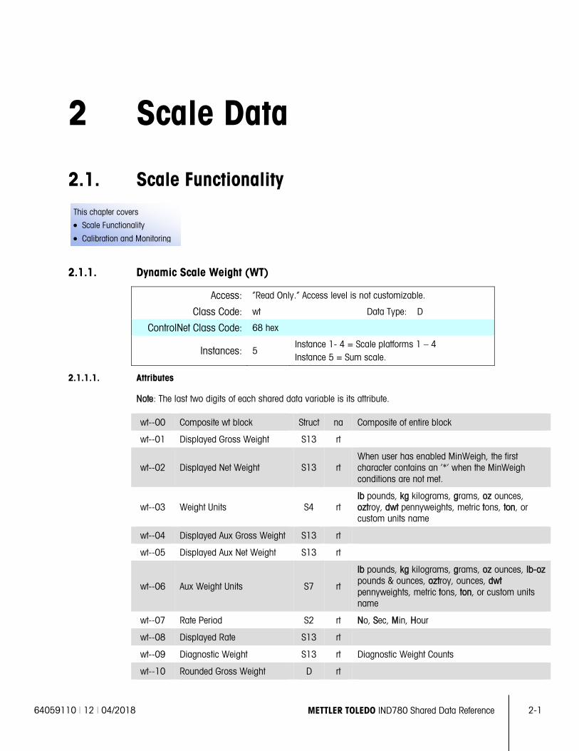
2.1. Scale Functionality
2.1.1. Dynamic Scale Weight (WT)
Access: “Read Only.” Access level is not customizable.
Class Code: wt Data Type: D
ControlNet Class Code: 68 hex
Instances: 5 Instance 1- 4 = Scale platforms 1 – 4 Instance 5 = Sum scale.
2.1.1.1. Attributes
Note: The last two digits of each shared data variable is its attribute.
wt--00 Composite wt block Struct na Composite of entire block
wt--01 Displayed Gross Weight S13 rt
wt--02 Displayed Net Weight S13 rt When user has enabled MinWeigh, the first character contains an ‘*’ when the MinWeigh conditions are not met.
wt--03 Weight Units S4 rt lb pounds, kg kilograms, grams, oz ounces, oztroy, dwt pennyweights, metric tons, ton, or custom units name
wt--04 Displayed Aux Gross Weight S13 rt
wt--05 Displayed Aux Net Weight S13 rt
wt--06 Aux Weight Units S7 rt
lb pounds, kg kilograms, grams, oz ounces, lb-oz pounds & ounces, oztroy, ounces, dwt pennyweights, metric tons, ton, or custom units name
wt--07 Rate Period S2 rt No, Sec, Min, Hour
wt--08 Displayed Rate S13 rt
wt--09 Diagnostic Weight S13 rt Diagnostic Weight Counts
wt--10 Rounded Gross Weight D rt
2-2 METTLER TOLEDO IND780 Shared Data Reference 64059110 | 12 | 04/2018
Scal
e D
ata
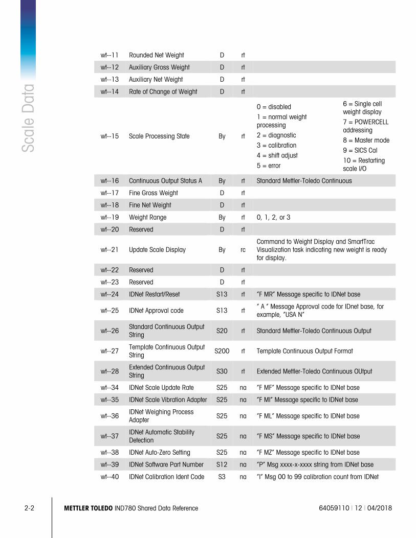
wt--11 Rounded Net Weight D rt
wt--12 Auxiliary Gross Weight D rt
wt--13 Auxiliary Net Weight D rt
wt--14 Rate of Change of Weight D rt
wt--15 Scale Processing State By rt
0 = disabled
1 = normal weight processing
2 = diagnostic
3 = calibration
4 = shift adjust
5 = error
6 = Single cell weight display
7 = POWERCELL addressing
8 = Master mode
9 = SICS Cal
10 = Restarting scale I/O
wt--16 Continuous Output Status A By rt Standard Mettler-Toledo Continuous
wt--17 Fine Gross Weight D rt
wt--18 Fine Net Weight D rt
wt--19 Weight Range By rt 0, 1, 2, or 3
wt--20 Reserved D rt
wt--21 Update Scale Display By rc Command to Weight Display and SmartTrac Visualization task indicating new weight is ready for display.
wt--22 Reserved D rt
wt--23 Reserved D rt
wt--24 IDNet Restart/Reset S13 rt “F MR” Message specific to IDNet base
wt--25 IDNet Approval code S13 rt “ A “ Message Approval code for IDnet base, for example, “USA N”
wt--26 Standard Continuous Output String S20 rt Standard Mettler-Toledo Continuous Output
wt--27 Template Continuous Output String
S200 rt Template Continuous Output Format
wt--28 Extended Continuous Output String S30 rt Extended Mettler-Toledo Continuous OUtput
wt--34 IDNet Scale Update Rate S25 na “F MF” Message specific to IDNet base
wt--35 IDNet Scale Vibration Adapter S25 na “F MI” Message specific to IDNet base
wt--36 IDNet Weighing Process Adapter S25 na “F ML” Message specific to IDNet base
wt--37 IDNet Automatic Stability Detection
S25 na “F MS” Message specific to IDNet base
wt--38 IDNet Auto-Zero Setting S25 na “F MZ” Message specific to IDNet base
wt--39 IDNet Software Part Number S12 na “P” Msg xxxx-x-xxxx string from IDNet base
wt--40 IDNet Calibration Ident Code S3 na “I” Msg 00 to 99 calibration count from IDNet
64059110 | 12 | 04/2018 METTLER TOLEDO IND780 Shared Data Reference 2-3
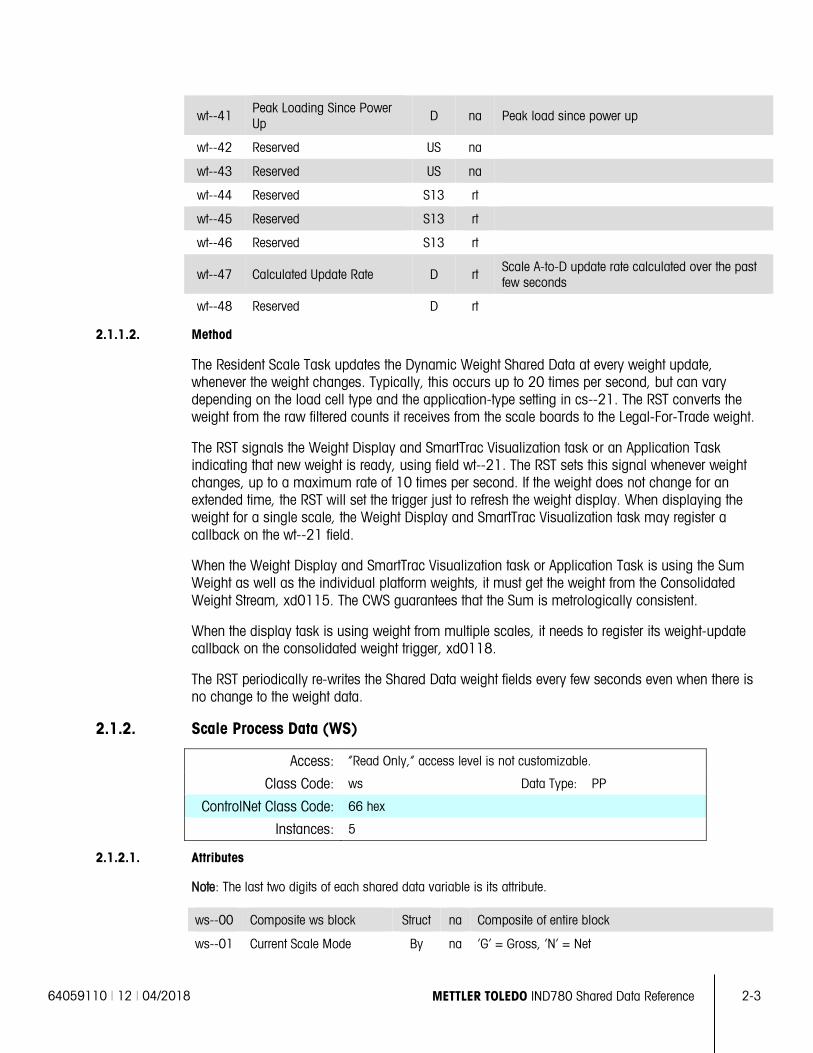
wt--41 Peak Loading Since Power Up D na Peak load since power up
wt--42 Reserved US na
wt--43 Reserved US na
wt--44 Reserved S13 rt
wt--45 Reserved S13 rt
wt--46 Reserved S13 rt
wt--47 Calculated Update Rate D rt Scale A-to-D update rate calculated over the past few seconds
wt--48 Reserved D rt
2.1.1.2. Method
The Resident Scale Task updates the Dynamic Weight Shared Data at every weight update, whenever the weight changes. Typically, this occurs up to 20 times per second, but can vary depending on the load cell type and the application-type setting in cs--21. The RST converts the weight from the raw filtered counts it receives from the scale boards to the Legal-For-Trade weight.
The RST signals the Weight Display and SmartTrac Visualization task or an Application Task indicating that new weight is ready, using field wt--21. The RST sets this signal whenever weight changes, up to a maximum rate of 10 times per second. If the weight does not change for an extended time, the RST will set the trigger just to refresh the weight display. When displaying the weight for a single scale, the Weight Display and SmartTrac Visualization task may register a callback on the wt--21 field.
When the Weight Display and SmartTrac Visualization task or Application Task is using the Sum Weight as well as the individual platform weights, it must get the weight from the Consolidated Weight Stream, xd0115. The CWS guarantees that the Sum is metrologically consistent.
When the display task is using weight from multiple scales, it needs to register its weight-update callback on the consolidated weight trigger, xd0118.
The RST periodically re-writes the Shared Data weight fields every few seconds even when there is no change to the weight data.
2.1.2. Scale Process Data (WS)
Access: “Read Only,” access level is not customizable.
Class Code: ws Data Type: PP
ControlNet Class Code: 66 hex
Instances: 5
2.1.2.1. Attributes
Note: The last two digits of each shared data variable is its attribute.
ws--00 Composite ws block Struct na Composite of entire block
ws--01 Current Scale Mode By na ‘G’ = Gross, ‘N’ = Net
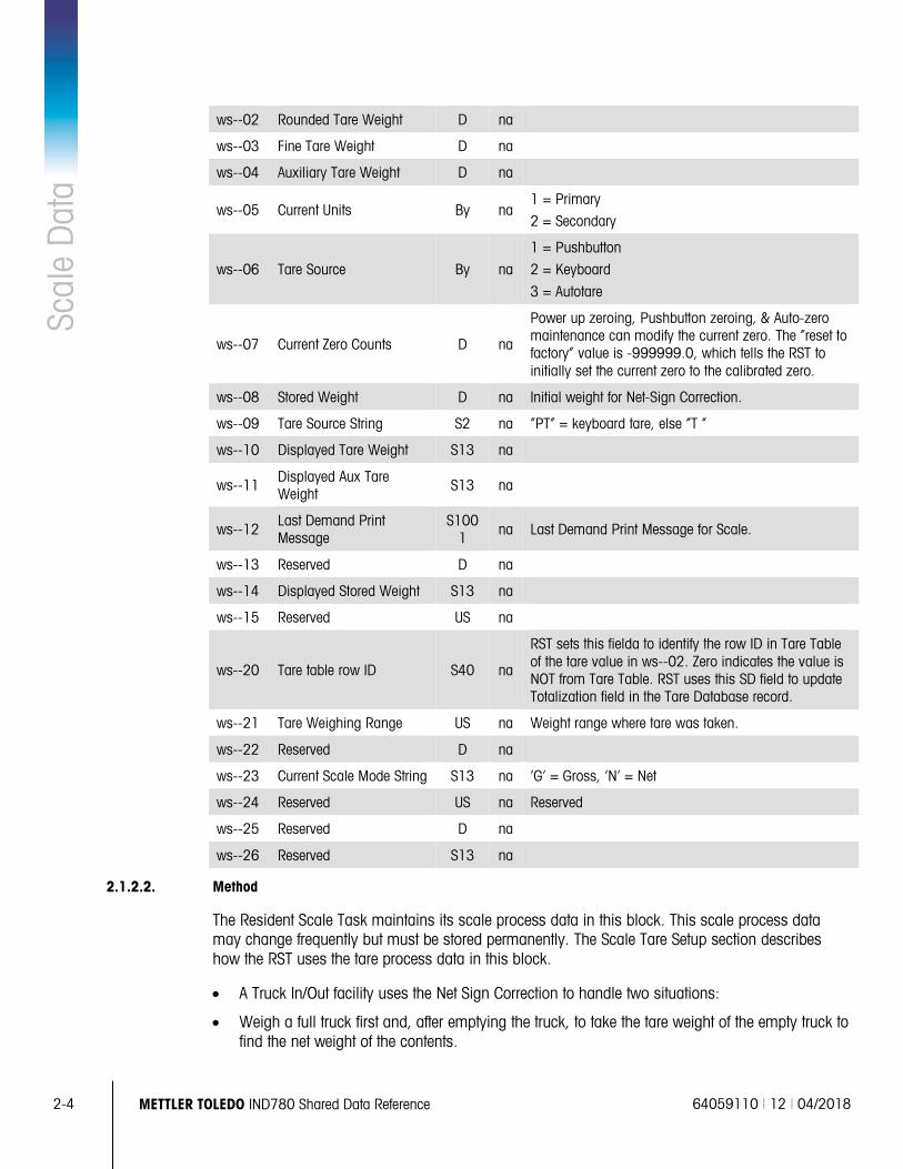
2-4 METTLER TOLEDO IND780 Shared Data Reference 64059110 | 12 | 04/2018
Scal
e D
ata
ws--02 Rounded Tare Weight D na
ws--03 Fine Tare Weight D na
ws--04 Auxiliary Tare Weight D na
ws--05 Current Units By na 1 = Primary
2 = Secondary
ws--06 Tare Source By na
1 = Pushbutton
2 = Keyboard
3 = Autotare
ws--07 Current Zero Counts D na
Power up zeroing, Pushbutton zeroing, & Auto-zero maintenance can modify the current zero. The “reset to factory” value is -999999.0, which tells the RST to initially set the current zero to the calibrated zero.
ws--08 Stored Weight D na Initial weight for Net-Sign Correction.
ws--09 Tare Source String S2 na “PT” = keyboard tare, else “T ”
ws--10 Displayed Tare Weight S13 na
ws--11 Displayed Aux Tare Weight
S13 na
ws--12 Last Demand Print Message
S1001 na Last Demand Print Message for Scale.
ws--13 Reserved D na
ws--14 Displayed Stored Weight S13 na
ws--15 Reserved US na
ws--20 Tare table row ID S40 na
RST sets this fielda to identify the row ID in Tare Table of the tare value in ws--02. Zero indicates the value is NOT from Tare Table. RST uses this SD field to update Totalization field in the Tare Database record.
ws--21 Tare Weighing Range US na Weight range where tare was taken.
ws--22 Reserved D na
ws--23 Current Scale Mode String S13 na ‘G’ = Gross, ‘N’ = Net
ws--24 Reserved US na Reserved
ws--25 Reserved D na
ws--26 Reserved S13 na
2.1.2.2. Method
The Resident Scale Task maintains its scale process data in this block. This scale process data may change frequently but must be stored permanently. The Scale Tare Setup section describes how the RST uses the tare process data in this block.
• A Truck In/Out facility uses the Net Sign Correction to handle two situations:
• Weigh a full truck first and, after emptying the truck, to take the tare weight of the empty truck to find the net weight of the contents.
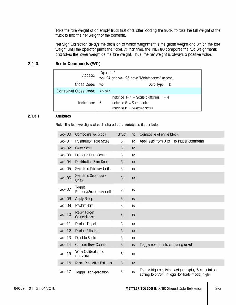
64059110 | 12 | 04/2018 METTLER TOLEDO IND780 Shared Data Reference 2-5
Take the tare weight of an empty truck first and, after loading the truck, to take the full weight of the truck to find the net weight of the contents.
Net Sign Correction delays the decision of which weighment is the gross weight and which the tare weight until the operator prints the ticket. At that time, the IND780 compares the two weighments and takes the lower weight as the tare weight. Thus, the net weight is always a positive value.
2.1.3. Scale Commands (WC)
Access: “Operator” wc--24 and wc--25 have “Maintenance” access
Class Code: wc Data Type: D
ControlNet Class Code: 76 hex
Instances: 6 Instance 1- 4 = Scale platforms 1 – 4 Instance 5 = Sum scale Instance 6 = Selected scale
2.1.3.1. Attributes
Note: The last two digits of each shared data variable is its attribute.
wc--00 Composite wc block Struct na Composite of entire block
wc--01 Pushbutton Tare Scale Bl rc Appl. sets from 0 to 1 to trigger command
wc--02 Clear Scale Bl rc
wc--03 Demand Print Scale Bl rc
wc--04 Pushbutton Zero Scale Bl rc
wc--05 Switch to Primary Units Bl rc
wc--06 Switch to Secondary Units
Bl rc
wc--07 Toggle Primary/Secondary units
Bl rc
wc--08 Apply Setup Bl rc
wc--09 Restart Rate Bl rc
wc--10 Reset Target Coincidence
Bl rc
wc--11 Restart Target Bl rc
wc--12 Restart Filtering Bl rc
wc--13 Disable Scale Bl rc
wc--14 Capture Raw Counts Bl rc Toggle raw counts capturing on/off
wc--15 Write Calibration to EEPROM
Bl rc
wc--16 Reset Predictive Failures Bl rc
wc--17 Toggle High-precision Bl rc Toggle high precision weight display & calculation setting to on/off. In legal-for-trade mode, high-
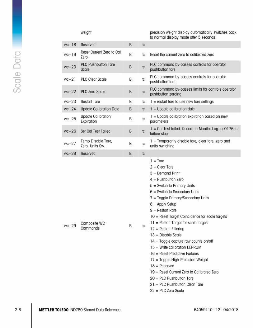
2-6 METTLER TOLEDO IND780 Shared Data Reference 64059110 | 12 | 04/2018
Scal
e D
ata
weight precision weight display automatically switches back to normal display mode after 5 seconds
wc--18 Reserved Bl rc
wc--19 Reset Current Zero to Cal Zero
Bl rc Reset the current zero to calibrated zero
wc--20 PLC Pushbutton Tare Scale Bl rc
PLC command by-passes controls for operator pushbutton tare
wc--21 PLC Clear Scale Bl rc PLC command by-passes controls for operator pushbutton tare
wc--22 PLC Zero Scale Bl rc PLC command by-passes limits for controls operator pushbutton zeroing
wc--23 Restart Tare Bl rc 1 = restart tare to use new tare settings
wc--24 Update Calibration Date Bl rc 1 = Update calibration date
wc--25 Update Calibration Expiration Bl rc
1 = Update calibration expiration based on new parameters
wc--26 Set Cal Test Failed Bl rc 1 = Cal Test failed. Record in Monitor Log. qc0176 is failure step
wc--27 Temp Disable Tare, Zero, Units Sw. Bl rc
1 = Temporarily disable tare, clear tare, zero and units switching
wc--28 Reserved Bl rc
wc--29 Composite WC Commands Bl rc
1 = Tare
2 = Clear Tare
3 = Demand Print
4 = Pushbutton Zero
5 = Switch to Primary Units
6 = Switch to Secondary Units
7 = Toggle Primary/Secondary Units
8 = Apply Setup
9 = Restart Rate
10 = Reset Target Coincidence for scale targets
11 = Restart Target for scale targest
12 = Restart Filtering
13 = Disable Scale
14 = Toggle capture raw counts on/off
15 = Write calibration EEPROM
16 = Reset Predictive Failures
17 = Toggle High-Precision Weight
18 = Reserved
19 = Reset Current Zero to Calibrated Zero
20 = PLC Pushbutton Tare
21 = PLC Pushbutton Clear Tare
22 = PLC Zero Scale
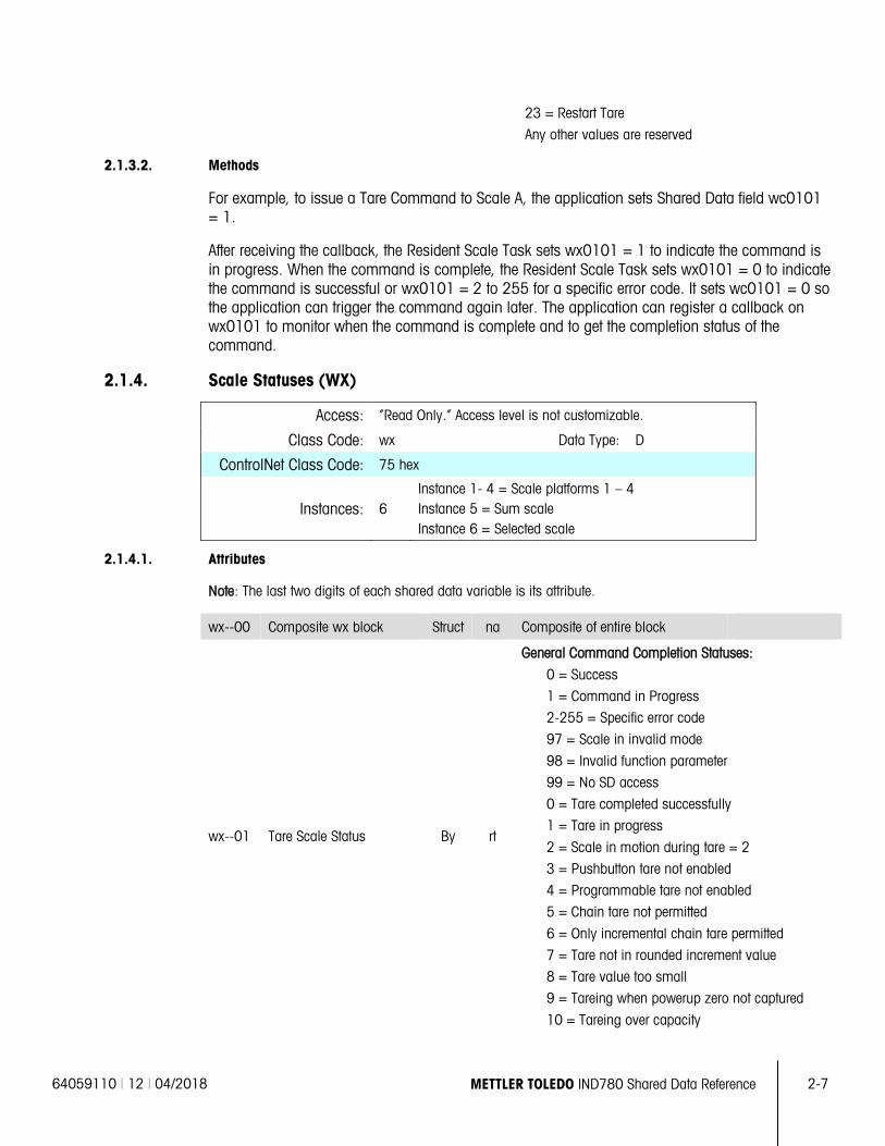
64059110 | 12 | 04/2018 METTLER TOLEDO IND780 Shared Data Reference 2-7
23 = Restart Tare
Any other values are reserved
2.1.3.2. Methods
For example, to issue a Tare Command to Scale A, the application sets Shared Data field wc0101 = 1.
After receiving the callback, the Resident Scale Task sets wx0101 = 1 to indicate the command is in progress. When the command is complete, the Resident Scale Task sets wx0101 = 0 to indicate the command is successful or wx0101 = 2 to 255 for a specific error code. It sets wc0101 = 0 so the application can trigger the command again later. The application can register a callback on wx0101 to monitor when the command is complete and to get the completion status of the command.
2.1.4. Scale Statuses (WX)
Access: “Read Only.” Access level is not customizable.
Class Code: wx Data Type: D
ControlNet Class Code: 75 hex
Instances: 6 Instance 1- 4 = Scale platforms 1 – 4 Instance 5 = Sum scale Instance 6 = Selected scale
2.1.4.1. Attributes
Note: The last two digits of each shared data variable is its attribute.
wx--00 Composite wx block Struct na Composite of entire block
wx--01 Tare Scale Status By rt
General Command Completion Statuses:
0 = Success
1 = Command in Progress
2-255 = Specific error code
97 = Scale in invalid mode
98 = Invalid function parameter
99 = No SD access
0 = Tare completed successfully
1 = Tare in progress
2 = Scale in motion during tare = 2
3 = Pushbutton tare not enabled
4 = Programmable tare not enabled
5 = Chain tare not permitted
6 = Only incremental chain tare permitted
7 = Tare not in rounded increment value
8 = Tare value too small
9 = Tareing when powerup zero not captured
10 = Tareing over capacity
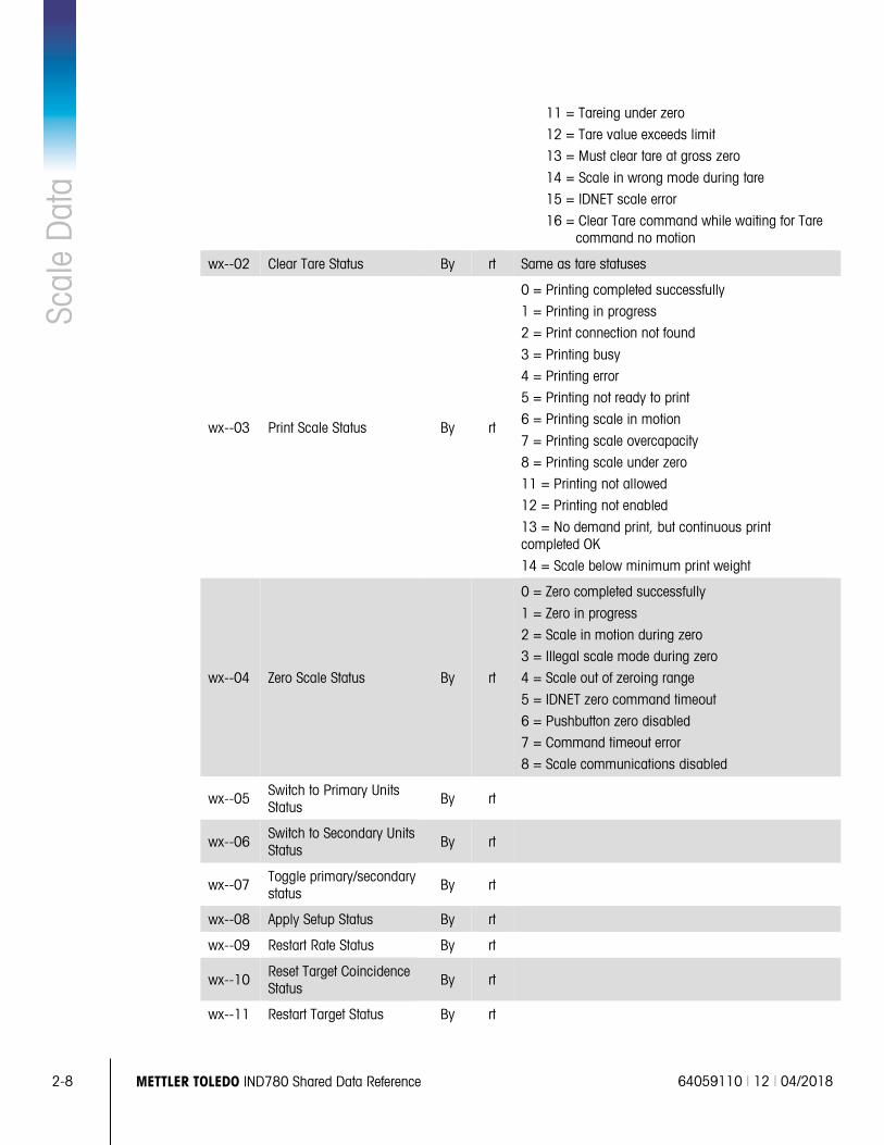
2-8 METTLER TOLEDO IND780 Shared Data Reference 64059110 | 12 | 04/2018
Scal
e D
ata
11 = Tareing under zero
12 = Tare value exceeds limit
13 = Must clear tare at gross zero
14 = Scale in wrong mode during tare
15 = IDNET scale error
16 = Clear Tare command while waiting for Tare command no motion
wx--02 Clear Tare Status By rt Same as tare statuses
wx--03 Print Scale Status By rt
0 = Printing completed successfully
1 = Printing in progress
2 = Print connection not found
3 = Printing busy
4 = Printing error
5 = Printing not ready to print
6 = Printing scale in motion
7 = Printing scale overcapacity
8 = Printing scale under zero
11 = Printing not allowed
12 = Printing not enabled
13 = No demand print, but continuous print completed OK
14 = Scale below minimum print weight
wx--04 Zero Scale Status By rt
0 = Zero completed successfully
1 = Zero in progress
2 = Scale in motion during zero
3 = Illegal scale mode during zero
4 = Scale out of zeroing range
5 = IDNET zero command timeout
6 = Pushbutton zero disabled
7 = Command timeout error
8 = Scale communications disabled
wx--05 Switch to Primary Units Status
By rt
wx--06 Switch to Secondary Units Status By rt
wx--07 Toggle primary/secondary status
By rt
wx--08 Apply Setup Status By rt
wx--09 Restart Rate Status By rt
wx--10 Reset Target Coincidence Status
By rt
wx--11 Restart Target Status By rt
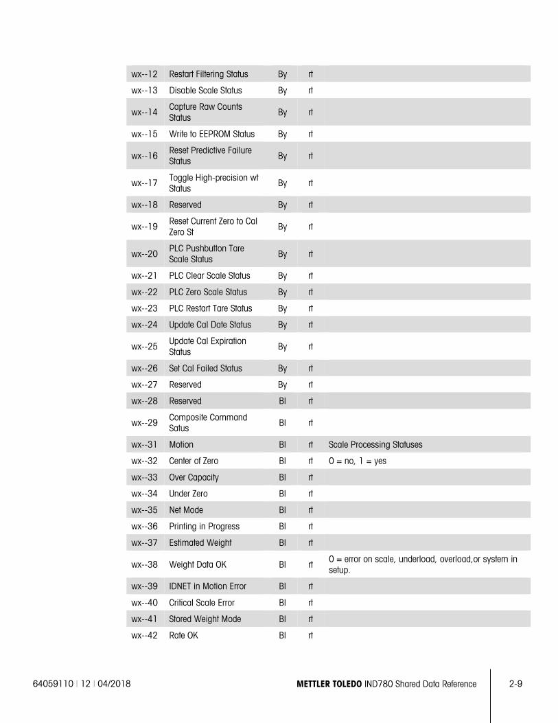
64059110 | 12 | 04/2018 METTLER TOLEDO IND780 Shared Data Reference 2-9
wx--12 Restart Filtering Status By rt
wx--13 Disable Scale Status By rt
wx--14 Capture Raw Counts Status
By rt
wx--15 Write to EEPROM Status By rt
wx--16 Reset Predictive Failure Status By rt
wx--17 Toggle High-precision wt Status
By rt
wx--18 Reserved By rt
wx--19 Reset Current Zero to Cal Zero St
By rt
wx--20 PLC Pushbutton Tare Scale Status By rt
wx--21 PLC Clear Scale Status By rt
wx--22 PLC Zero Scale Status By rt
wx--23 PLC Restart Tare Status By rt
wx--24 Update Cal Date Status By rt
wx--25 Update Cal Expiration Status
By rt
wx--26 Set Cal Failed Status By rt
wx--27 Reserved By rt
wx--28 Reserved Bl rt
wx--29 Composite Command Satus
Bl rt
wx--31 Motion Bl rt Scale Processing Statuses
wx--32 Center of Zero Bl rt 0 = no, 1 = yes
wx--33 Over Capacity Bl rt
wx--34 Under Zero Bl rt
wx--35 Net Mode Bl rt
wx--36 Printing in Progress Bl rt
wx--37 Estimated Weight Bl rt
wx--38 Weight Data OK Bl rt 0 = error on scale, underload, overload,or system in setup.
wx--39 IDNET in Motion Error Bl rt
wx--40 Critical Scale Error Bl rt
wx--41 Stored Weight Mode Bl rt
wx--42 Rate OK Bl rt
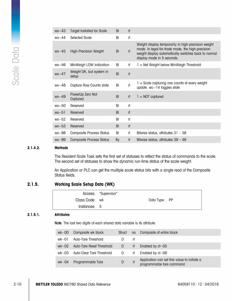
2-10 METTLER TOLEDO IND780 Shared Data Reference 64059110 | 12 | 04/2018
Scal
e D
ata
wx--43 Target Installed for Scale Bl rt
wx--44 Selected Scale Bl rt
wx--45 High-Precision Weight Bl rt
Weight display temporarily in high-precision weight mode. In legal-for-trade mode, the high-precision weight display automatically switches back to normal display mode in 5 seconds.
wx--46 MinWeigh LOW indication Bl rt 1 = Net Weight below MinWeigh Threshold
wx--47 Weight OK, but system in setup
Bl rt
wx--48 Capture Raw Counts state Bl rt 1 = Scale capturing raw counts at every weight update. wc--14 toggles state
wx--49 PowerUp Zero Not Captured
Bl rt 1 = NOT captured
wx--50 Reserved Bl rt
wx--51 Reserved Bl rt
wx--52 Reserved Bl rt
wx--53 Reserved Bl rt
wx--98 Composite Process Status Bl rt Bitwise status, attributes 31 – 38
wx--99 Composite Process Status By rt Bitwise status, attributes 39 – 46
2.1.4.2. Methods
The Resident Scale Task sets the first set of statuses to reflect the status of commands to the scale. The second set of statuses to show the dynamic run-time status of the scale weight.
An Application or PLC can get the multiple scale status bits with a single read of the Composite Status fields.
2.1.5. Working Scale Setup Data (WK)
Access: “Supervisor”
Class Code: wk Data Type: PP
Instances: 5
2.1.5.1. Attributes
Note: The last two digits of each shared data variable is its attribute.
wk--00 Composite wk block Struct na Composite of entire block
wk--01 Auto-Tare Threshold D rt
wk--02 Auto-Tare Reset Threshold D rt Enabled by ct--05
wk--03 Auto-Clear Tare Threshold D rt Enabled by ct--06
wk--04 Programmable Tare D rt Application can set this value to initiate a programmable tare command
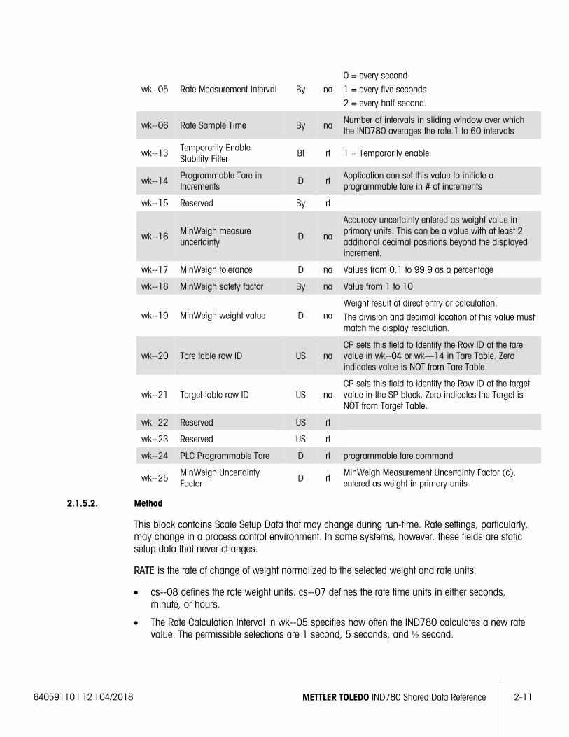
64059110 | 12 | 04/2018 METTLER TOLEDO IND780 Shared Data Reference 2-11
wk--05 Rate Measurement Interval By na
0 = every second
1 = every five seconds
2 = every half-second.
wk--06 Rate Sample Time By na Number of intervals in sliding window over which the IND780 averages the rate.1 to 60 intervals
wk--13 Temporarily Enable Stability Filter Bl rt 1 = Temporarily enable
wk--14 Programmable Tare in Increments
D rt Application can set this value to initiate a programmable tare in # of increments
wk--15 Reserved By rt
wk--16 MinWeigh measure uncertainty
D na
Accuracy uncertainty entered as weight value in primary units. This can be a value with at least 2 additional decimal positions beyond the displayed increment.
wk--17 MinWeigh tolerance D na Values from 0.1 to 99.9 as a percentage
wk--18 MinWeigh safety factor By na Value from 1 to 10
wk--19 MinWeigh weight value D na Weight result of direct entry or calculation.
The division and decimal location of this value must match the display resolution.
wk--20 Tare table row ID US na CP sets this field to Identify the Row ID of the tare value in wk--04 or wk—14 in Tare Table. Zero indicates value is NOT from Tare Table.
wk--21 Target table row ID US na CP sets this field to identify the Row ID of the target value in the SP block. Zero indicates the Target is NOT from Target Table.
wk--22 Reserved US rt
wk--23 Reserved US rt
wk--24 PLC Programmable Tare D rt programmable tare command
wk--25 MinWeigh Uncertainty Factor D rt
MinWeigh Measurement Uncertainty Factor (c), entered as weight in primary units
2.1.5.2. Method
This block contains Scale Setup Data that may change during run-time. Rate settings, particularly, may change in a process control environment. In some systems, however, these fields are static setup data that never changes.
RATE is the rate of change of weight normalized to the selected weight and rate units.
• cs--08 defines the rate weight units. cs--07 defines the rate time units in either seconds, minute, or hours.
• The Rate Calculation Interval in wk--05 specifies how often the IND780 calculates a new rate value. The permissible selections are 1 second, 5 seconds, and ½ second.
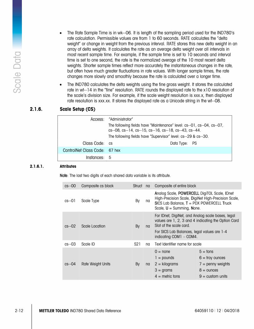
2-12 METTLER TOLEDO IND780 Shared Data Reference 64059110 | 12 | 04/2018
Scal
e D
ata
• The Rate Sample Time is in wk--06. It is length of the sampling period used for the IND780’s rate calculation. Permissible values are from 1 to 60 seconds. RATE calculates the “delta weight” or change in weight from the previous interval. RATE stores this new delta weight in an array of delta weights. It calculates the rate as an average delta weight over all intervals in most recent sample time. For example, if the sample time is set to 10 seconds and interval time is set to one second, the rate is the normalized average of the 10 most recent delta weights. Shorter sample times reflect more accurately the instantaneous changes in the rate, but often have much greater fluctuations in rate values. With longer sample times, the rate changes more slowly and smoothly because the rate is calculated over a longer time.
• The IND780 calculates the delta weights using the fine gross weight. It stores the calculated rate in wt--14 in the “fine” resolution. RATE rounds the displayed rate to the x10 resolution of the scale’s division size. For example, if the scale weight resolution is xxx.x, then displayed rate resolution is xxx.xx. It stores the displayed rate as a Unicode string in the wt--08.
2.1.6. Scale Setup (CS)
Access: “Administrator”
The following fields have “Maintenance” level: cs--01, cs--04, cs--07, cs--08, cs--14, cs--15, cs--16, cs--18, cs--43, cs--44. The following fields have “Supervisor” level: cs--29 & cs--30.
Class Code: cs Data Type: PS
ControlNet Class Code: 67 hex
Instances: 5
2.1.6.1. Attributes
Note: The last two digits of each shared data variable is its attribute.
cs--00 Composite cs block Struct na Composite of entire block
cs--01 Scale Type By na
Analog Scale, POWERCELL DigiTOL Scale, IDnet High-Precision Scale, DigiNet High-Precision Scale, SICS Lab Balance, T = PDX POWERCELL Truck Scale, U = Summing, None.
cs--02 Scale Location By na
For IDnet, DigiNet, and Analog scale bases, legal values are 1, 2, 3 and 4 indicating the Option Card Slot of the scale card.
For SICS Lab Balances, legal values are 1-4 indicating COM1 – COM4.
cs--03 Scale ID S21 na Text Identifier name for scale
cs--04 Rate Weight Units By na
0 = none
1 = pounds
2 = kilograms
3 = grams
4 = metric tons
5 = tons
6 = troy ounces
7 = penny weights
8 = ounces
9 = custom units
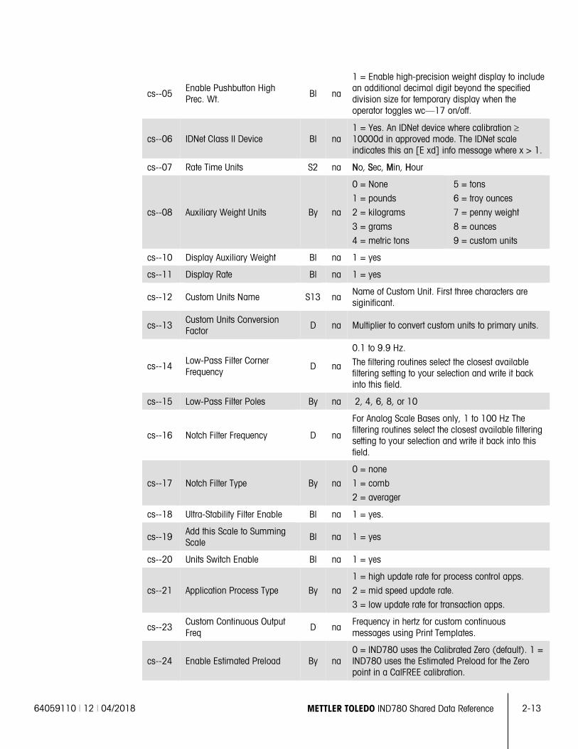
64059110 | 12 | 04/2018 METTLER TOLEDO IND780 Shared Data Reference 2-13
cs--05 Enable Pushbutton High Prec. Wt. Bl na
1 = Enable high-precision weight display to include an additional decimal digit beyond the specified division size for temporary display when the operator toggles wc—17 on/off.
cs--06 IDNet Class II Device Bl na 1 = Yes. An IDNet device where calibration ≥ 10000d in approved mode. The IDNet scale indicates this an [E xd] info message where x > 1.
cs--07 Rate Time Units S2 na No, Sec, Min, Hour
cs--08 Auxiliary Weight Units By na
0 = None
1 = pounds
2 = kilograms
3 = grams
4 = metric tons
5 = tons
6 = troy ounces
7 = penny weight
8 = ounces
9 = custom units
cs--10 Display Auxiliary Weight Bl na 1 = yes
cs--11 Display Rate Bl na 1 = yes
cs--12 Custom Units Name S13 na Name of Custom Unit. First three characters are siginificant.
cs--13 Custom Units Conversion Factor D na Multiplier to convert custom units to primary units.
cs--14 Low-Pass Filter Corner Frequency
D na
0.1 to 9.9 Hz.
The filtering routines select the closest available filtering setting to your selection and write it back into this field.
cs--15 Low-Pass Filter Poles By na 2, 4, 6, 8, or 10
cs--16 Notch Filter Frequency D na
For Analog Scale Bases only, 1 to 100 Hz The filtering routines select the closest available filtering setting to your selection and write it back into this field.
cs--17 Notch Filter Type By na
0 = none
1 = comb
2 = averager
cs--18 Ultra-Stability Filter Enable Bl na 1 = yes.
cs--19 Add this Scale to Summing Scale
Bl na 1 = yes
cs--20 Units Switch Enable Bl na 1 = yes
cs--21 Application Process Type By na
1 = high update rate for process control apps.
2 = mid speed update rate.
3 = low update rate for transaction apps.
cs--23 Custom Continuous Output Freq
D na Frequency in hertz for custom continuous messages using Print Templates.
cs--24 Enable Estimated Preload By na 0 = IND780 uses the Calibrated Zero (default). 1 = IND780 uses the Estimated Preload for the Zero point in a CalFREE calibration.
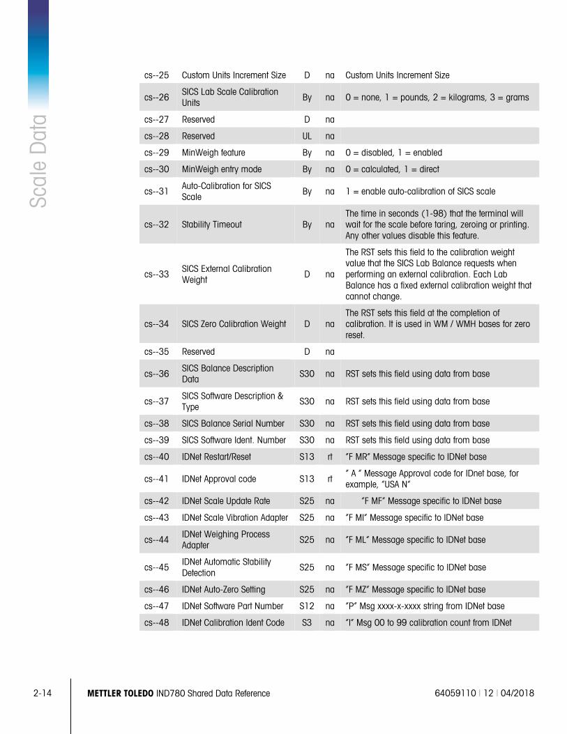
2-14 METTLER TOLEDO IND780 Shared Data Reference 64059110 | 12 | 04/2018
Scal
e D
ata
cs--25 Custom Units Increment Size D na Custom Units Increment Size
cs--26 SICS Lab Scale Calibration Units By na 0 = none, 1 = pounds, 2 = kilograms, 3 = grams
cs--27 Reserved D na
cs--28 Reserved UL na
cs--29 MinWeigh feature By na 0 = disabled, 1 = enabled
cs--30 MinWeigh entry mode By na 0 = calculated, 1 = direct
cs--31 Auto-Calibration for SICS Scale
By na 1 = enable auto-calibration of SICS scale
cs--32 Stability Timeout By na The time in seconds (1-98) that the terminal will wait for the scale before taring, zeroing or printing. Any other values disable this feature.
cs--33 SICS External Calibration Weight
D na
The RST sets this field to the calibration weight value that the SICS Lab Balance requests when performing an external calibration. Each Lab Balance has a fixed external calibration weight that cannot change.
cs--34 SICS Zero Calibration Weight D na The RST sets this field at the completion of calibration. It is used in WM / WMH bases for zero reset.
cs--35 Reserved D na
cs--36 SICS Balance Description Data S30 na RST sets this field using data from base
cs--37 SICS Software Description & Type
S30 na RST sets this field using data from base
cs--38 SICS Balance Serial Number S30 na RST sets this field using data from base
cs--39 SICS Software Ident. Number S30 na RST sets this field using data from base
cs--40 IDNet Restart/Reset S13 rt “F MR” Message specific to IDNet base
cs--41 IDNet Approval code S13 rt “ A “ Message Approval code for IDnet base, for example, “USA N”
cs--42 IDNet Scale Update Rate S25 na “F MF” Message specific to IDNet base
cs--43 IDNet Scale Vibration Adapter S25 na “F MI” Message specific to IDNet base
cs--44 IDNet Weighing Process Adapter S25 na “F ML” Message specific to IDNet base
cs--45 IDNet Automatic Stability Detection
S25 na “F MS” Message specific to IDNet base
cs--46 IDNet Auto-Zero Setting S25 na “F MZ” Message specific to IDNet base
cs--47 IDNet Software Part Number S12 na “P” Msg xxxx-x-xxxx string from IDNet base
cs--48 IDNet Calibration Ident Code S3 na “I” Msg 00 to 99 calibration count from IDNet
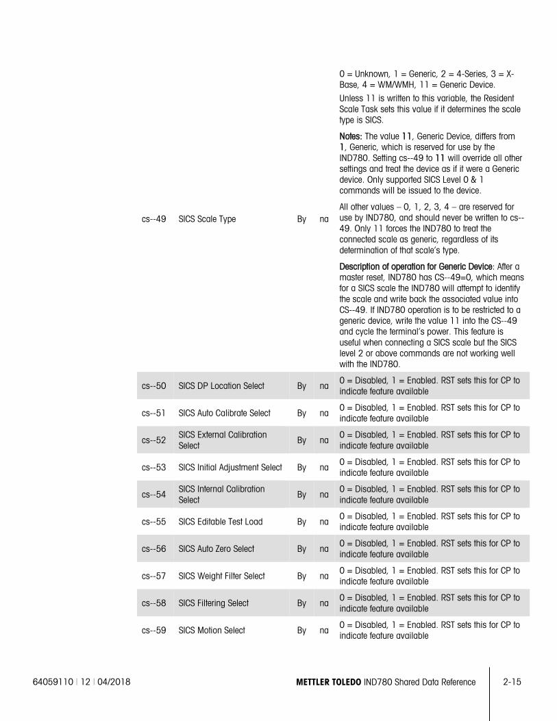
64059110 | 12 | 04/2018 METTLER TOLEDO IND780 Shared Data Reference 2-15
cs--49 SICS Scale Type By na
0 = Unknown, 1 = Generic, 2 = 4-Series, 3 = X-Base, 4 = WM/WMH, 11 = Generic Device.
Unless 11 is written to this variable, the Resident Scale Task sets this value if it determines the scale type is SICS.
Notes: The value 11, Generic Device, differs from 1, Generic, which is reserved for use by the IND780. Setting cs--49 to 11 will override all other settings and treat the device as if it were a Generic device. Only supported SICS Level 0 & 1 commands will be issued to the device.
All other values – 0, 1, 2, 3, 4 – are reserved for use by IND780, and should never be written to cs--49. Only 11 forces the IND780 to treat the connected scale as generic, regardless of its determination of that scale’s type.
Description of operation for Generic Device: After a master reset, IND780 has CS--49=0, which means for a SICS scale the IND780 will attempt to identify the scale and write back the associated value into CS--49. If IND780 operation is to be restricted to a generic device, write the value 11 into the CS--49 and cycle the terminal’s power. This feature is useful when connecting a SICS scale but the SICS level 2 or above commands are not working well with the IND780.
cs--50 SICS DP Location Select By na 0 = Disabled, 1 = Enabled. RST sets this for CP to indicate feature available
cs--51 SICS Auto Calibrate Select By na 0 = Disabled, 1 = Enabled. RST sets this for CP to indicate feature available
cs--52 SICS External Calibration Select
By na 0 = Disabled, 1 = Enabled. RST sets this for CP to indicate feature available
cs--53 SICS Initial Adjustment Select By na 0 = Disabled, 1 = Enabled. RST sets this for CP to indicate feature available
cs--54 SICS Internal Calibration Select
By na 0 = Disabled, 1 = Enabled. RST sets this for CP to indicate feature available
cs--55 SICS Editable Test Load By na 0 = Disabled, 1 = Enabled. RST sets this for CP to indicate feature available
cs--56 SICS Auto Zero Select By na 0 = Disabled, 1 = Enabled. RST sets this for CP to indicate feature available
cs--57 SICS Weight Filter Select By na 0 = Disabled, 1 = Enabled. RST sets this for CP to indicate feature available
cs--58 SICS Filtering Select By na 0 = Disabled, 1 = Enabled. RST sets this for CP to indicate feature available
cs--59 SICS Motion Select By na 0 = Disabled, 1 = Enabled. RST sets this for CP to indicate feature available
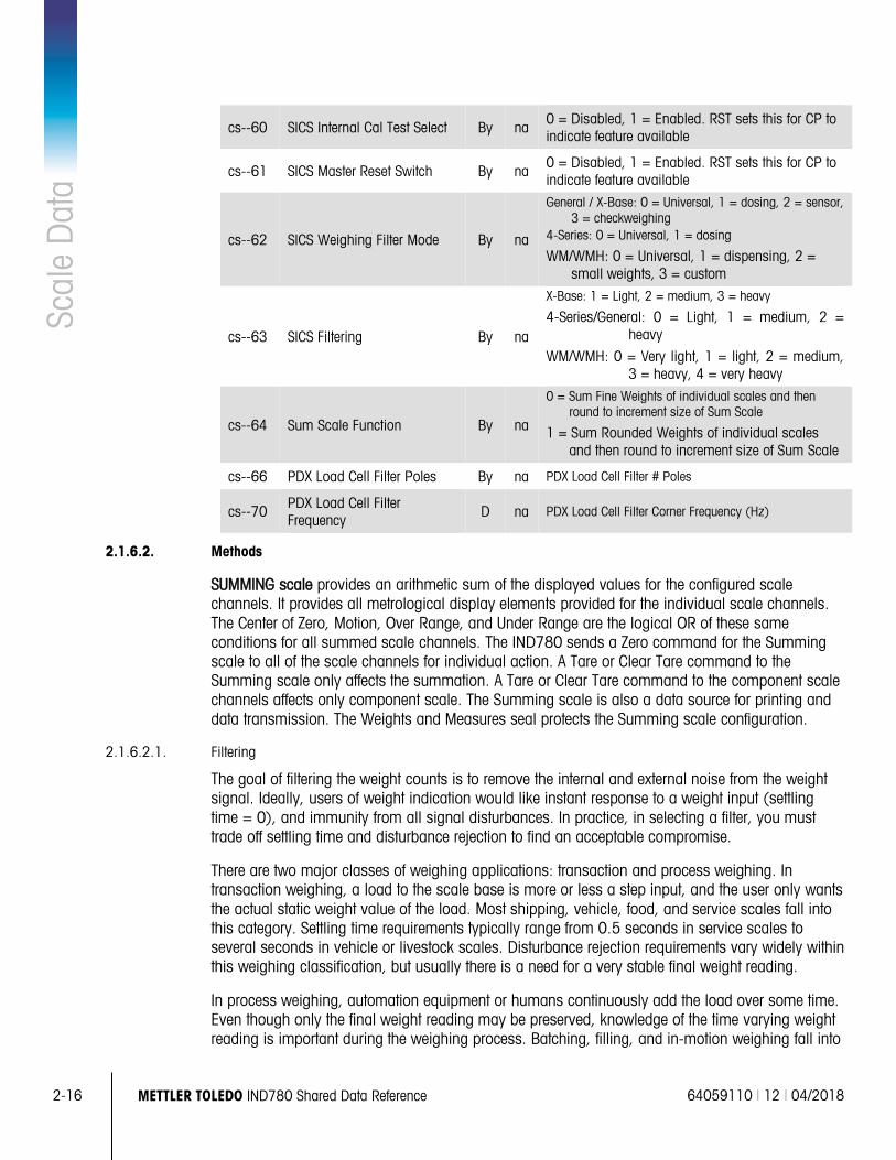
2-16 METTLER TOLEDO IND780 Shared Data Reference 64059110 | 12 | 04/2018
Scal
e D
ata
cs--60 SICS Internal Cal Test Select By na 0 = Disabled, 1 = Enabled. RST sets this for CP to indicate feature available
cs--61 SICS Master Reset Switch By na 0 = Disabled, 1 = Enabled. RST sets this for CP to indicate feature available
cs--62 SICS Weighing Filter Mode By na
General / X-Base: 0 = Universal, 1 = dosing, 2 = sensor, 3 = checkweighing
4-Series: 0 = Universal, 1 = dosing
WM/WMH: 0 = Universal, 1 = dispensing, 2 = small weights, 3 = custom
cs--63 SICS Filtering By na
X-Base: 1 = Light, 2 = medium, 3 = heavy
4-Series/General: 0 = Light, 1 = medium, 2 = heavy
WM/WMH: 0 = Very light, 1 = light, 2 = medium, 3 = heavy, 4 = very heavy
cs--64 Sum Scale Function By na
0 = Sum Fine Weights of individual scales and then round to increment size of Sum Scale
1 = Sum Rounded Weights of individual scales and then round to increment size of Sum Scale
cs--66 PDX Load Cell Filter Poles By na PDX Load Cell Filter # Poles
cs--70 PDX Load Cell Filter Frequency
D na PDX Load Cell Filter Corner Frequency (Hz)
2.1.6.2. Methods
SUMMING scale provides an arithmetic sum of the displayed values for the configured scale channels. It provides all metrological display elements provided for the individual scale channels. The Center of Zero, Motion, Over Range, and Under Range are the logical OR of these same conditions for all summed scale channels. The IND780 sends a Zero command for the Summing scale to all of the scale channels for individual action. A Tare or Clear Tare command to the Summing scale only affects the summation. A Tare or Clear Tare command to the component scale channels affects only component scale. The Summing scale is also a data source for printing and data transmission. The Weights and Measures seal protects the Summing scale configuration.
2.1.6.2.1. Filtering
The goal of filtering the weight counts is to remove the internal and external noise from the weight signal. Ideally, users of weight indication would like instant response to a weight input (settling time = 0), and immunity from all signal disturbances. In practice, in selecting a filter, you must trade off settling time and disturbance rejection to find an acceptable compromise.
There are two major classes of weighing applications: transaction and process weighing. In transaction weighing, a load to the scale base is more or less a step input, and the user only wants the actual static weight value of the load. Most shipping, vehicle, food, and service scales fall into this category. Settling time requirements typically range from 0.5 seconds in service scales to several seconds in vehicle or livestock scales. Disturbance rejection requirements vary widely within this weighing classification, but usually there is a need for a very stable final weight reading.
In process weighing, automation equipment or humans continuously add the load over some time. Even though only the final weight reading may be preserved, knowledge of the time varying weight reading is important during the weighing process. Batching, filling, and in-motion weighing fall into
64059110 | 12 | 04/2018 METTLER TOLEDO IND780 Shared Data Reference 2-17
this category. Settling time requirements are usually more relaxed because the “final” settling time for a ramp input is less than that of the same load applied as a step input. Disturbance rejection is important since many types of automation equipment introduce vibrations. Stability of the “final” value is somewhat less important.
IND780 filtering has a large range of adjustment for both disturbance rejection and settling time to meet all application requirements. Since these two parameters are dependent, some experimentation is usually required to find the best fit for the application.
The following describes the Analog Load Cell Interface filtering. The IND780 Analog Scale Interface provides a 366 Hz A/D sampling rate, which permits highly effective digital filtering. Since most of the filtering is digital, it is easily adjusted over a wide range of selections via soft switch setup to meet specific site needs. IND780 has three types of configurable digital filters:
1. Low Pass Filter
All weighing applications use the low pass filter. The user can specify the corner frequency of the pass band and the slope of the transition band. The pass band extends from DC (0 Hz) to the corner frequency. The low pass filter accepts the frequencies within this low-pass range with little or no attenuation, but attenuates frequencies above the pass band according to the slope of the transition band.
The scale is measuring the DC signal (static weight), so it is tempting to make the corner frequency very low to reject all “noise”. However, the narrower the pass band, the longer the delay or settling time before we get the final value. As the corner frequency is increased, the scale will settle faster, but will also allow more noise through.
The transition slope describes the rate of change of the attenuation once outside the pass band. The steeper the slope, the more effective a filter is at rejecting a disturbance that is near the corner frequency. Making the slope infinite will cut off all frequencies above the corner. Again the price is delay; the steeper the slope, the longer the settling time.
The IND780 provides a multi-pole Infinite Impulse Response (IIR) low pass digital filter, with Service Technician control over both the filter corner frequency and the sharpness of the transition band slope. The corner frequency is defined in Hz; its adjustment range is 0.2 through 10 Hz. The number of filter poles defines the band slope; there can be from 2 to 10 poles, providing cutoff slopes of -40 through -200 dB/decade. This large range of adjustability provides effective filtering for almost any situation.
2. Notch Filter
An ideal notch filter provides infinite attenuation at a single frequency, and little or no attenuation at other frequencies. This type of filter is useful in special cases where there is a single noise frequency near or below the corner frequency of the low pass filter. In such cases, use of the notch filter can provide additional attenuation for a troublesome noise source and may permit opening the pass band of the low pass filter for a faster step response. The IND780 implements the notch filter as a Finite Impulse Response (FIR) filter, and provides the fundamental notch plus additional notches at multiples of the fundamental notch frequency. Specifying the notch frequency in Hz adjusts the notch filter. The notch filter is applicable to all weighing applications, but only to the Analog Load Cell scale.
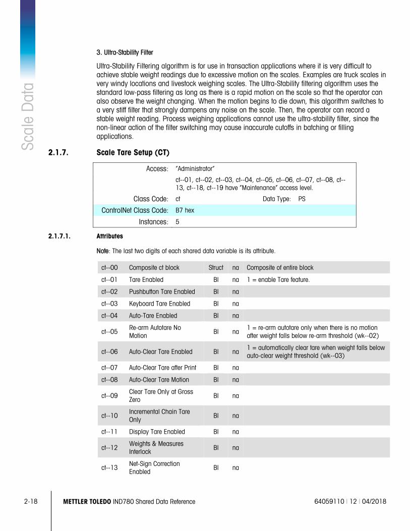
2-18 METTLER TOLEDO IND780 Shared Data Reference 64059110 | 12 | 04/2018
Scal
e D
ata
3. Ultra-Stability Filter
Ultra-Stability Filtering algorithm is for use in transaction applications where it is very difficult to achieve stable weight readings due to excessive motion on the scales. Examples are truck scales in very windy locations and livestock weighing scales. The Ultra-Stability filtering algorithm uses the standard low-pass filtering as long as there is a rapid motion on the scale so that the operator can also observe the weight changing. When the motion begins to die down, this algorithm switches to a very stiff filter that strongly dampens any noise on the scale. Then, the operator can record a stable weight reading. Process weighing applications cannot use the ultra-stability filter, since the non-linear action of the filter switching may cause inaccurate cutoffs in batching or filling applications.
2.1.7. Scale Tare Setup (CT)
Access: “Administrator”
ct--01, ct--02, ct--03, ct--04, ct--05, ct--06, ct--07, ct--08, ct--13, ct--18, ct--19 have “Maintenance” access level.
Class Code: ct Data Type: PS
ControlNet Class Code: B7 hex
Instances: 5
2.1.7.1. Attributes
Note: The last two digits of each shared data variable is its attribute.
ct--00 Composite ct block Struct na Composite of entire block
ct--01 Tare Enabled Bl na 1 = enable Tare feature.
ct--02 Pushbutton Tare Enabled Bl na
ct--03 Keyboard Tare Enabled Bl na
ct--04 Auto-Tare Enabled Bl na
ct--05 Re-arm Autotare No Motion
Bl na 1 = re-arm autotare only when there is no motion after weight falls below re-arm threshold (wk--02)
ct--06 Auto-Clear Tare Enabled Bl na 1 = automatically clear tare when weight falls below auto-clear weight threshold (wk--03)
ct--07 Auto-Clear Tare after Print Bl na
ct--08 Auto-Clear Tare Motion Bl na
ct--09 Clear Tare Only at Gross Zero Bl na
ct--10 Incremental Chain Tare Only
Bl na
ct--11 Display Tare Enabled Bl na
ct--12 Weights & Measures Interlock Bl na
ct--13 Net-Sign Correction Enabled
Bl na
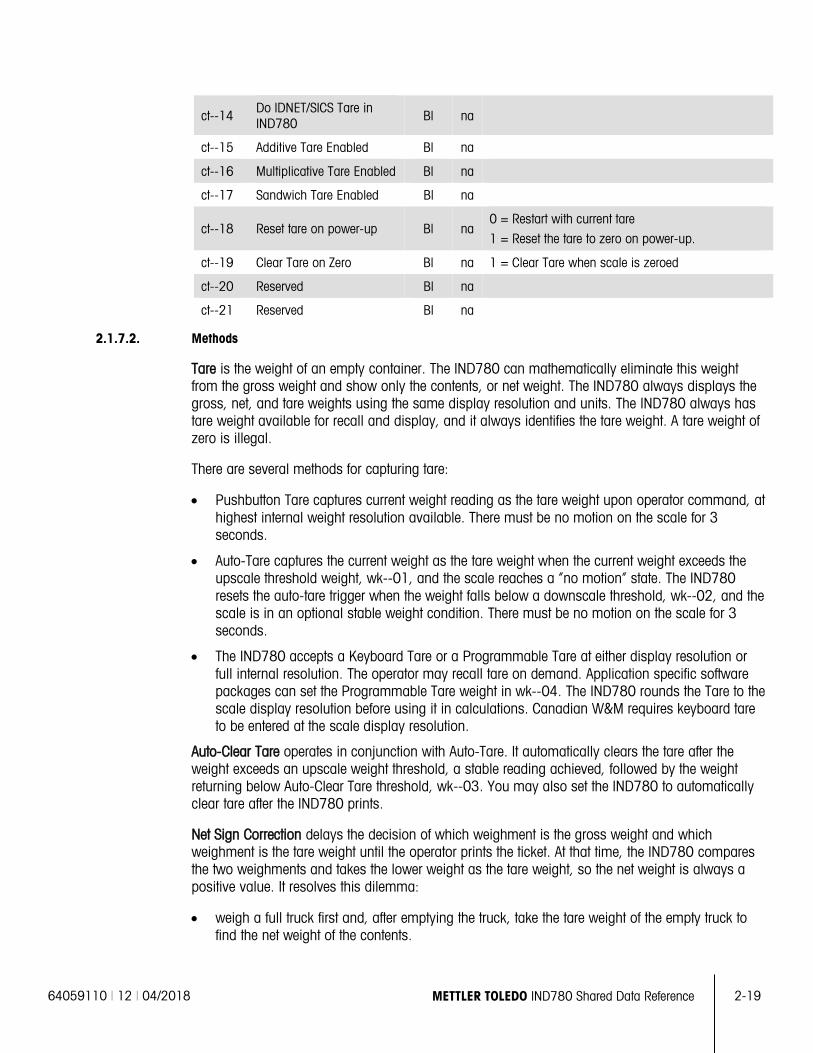
64059110 | 12 | 04/2018 METTLER TOLEDO IND780 Shared Data Reference 2-19
ct--14 Do IDNET/SICS Tare in IND780 Bl na
ct--15 Additive Tare Enabled Bl na
ct--16 Multiplicative Tare Enabled Bl na
ct--17 Sandwich Tare Enabled Bl na
ct--18 Reset tare on power-up Bl na 0 = Restart with current tare
1 = Reset the tare to zero on power-up.
ct--19 Clear Tare on Zero Bl na 1 = Clear Tare when scale is zeroed
ct--20 Reserved Bl na
ct--21 Reserved Bl na
2.1.7.2. Methods
Tare is the weight of an empty container. The IND780 can mathematically eliminate this weight from the gross weight and show only the contents, or net weight. The IND780 always displays the gross, net, and tare weights using the same display resolution and units. The IND780 always has tare weight available for recall and display, and it always identifies the tare weight. A tare weight of zero is illegal.
There are several methods for capturing tare:
• Pushbutton Tare captures current weight reading as the tare weight upon operator command, at highest internal weight resolution available. There must be no motion on the scale for 3 seconds.
• Auto-Tare captures the current weight as the tare weight when the current weight exceeds the upscale threshold weight, wk--01, and the scale reaches a “no motion” state. The IND780 resets the auto-tare trigger when the weight falls below a downscale threshold, wk--02, and the scale is in an optional stable weight condition. There must be no motion on the scale for 3 seconds.
• The IND780 accepts a Keyboard Tare or a Programmable Tare at either display resolution or full internal resolution. The operator may recall tare on demand. Application specific software packages can set the Programmable Tare weight in wk--04. The IND780 rounds the Tare to the scale display resolution before using it in calculations. Canadian W&M requires keyboard tare to be entered at the scale display resolution.
Auto-Clear Tare operates in conjunction with Auto-Tare. It automatically clears the tare after the weight exceeds an upscale weight threshold, a stable reading achieved, followed by the weight returning below Auto-Clear Tare threshold, wk--03. You may also set the IND780 to automatically clear tare after the IND780 prints.
Net Sign Correction delays the decision of which weighment is the gross weight and which weighment is the tare weight until the operator prints the ticket. At that time, the IND780 compares the two weighments and takes the lower weight as the tare weight, so the net weight is always a positive value. It resolves this dilemma:
• weigh a full truck first and, after emptying the truck, take the tare weight of the empty truck to find the net weight of the contents.
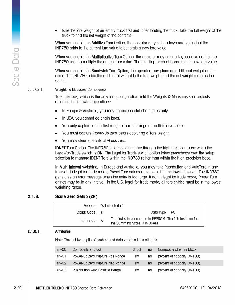
2-20 METTLER TOLEDO IND780 Shared Data Reference 64059110 | 12 | 04/2018
Scal
e D
ata
• take the tare weight of an empty truck first and, after loading the truck, take the full weight of the truck to find the net weight of the contents.
When you enable the Additive Tare Option, the operator may enter a keyboard value that the IND780 adds to the current tare value to generate a new tare value
When you enable the Multiplicative Tare Option, the operator may enter a keyboard value that the IND780 uses to multiply the current tare value. The resulting product becomes the new tare value.
When you enable the Sandwich Tare Option, the operator may place an additional weight on the scale. The IND780 adds the additional weight to the tare weight and the net weight remains the same.
2.1.7.2.1. Weights & Measures Compliance
Tare Interlock, which is the only tare configuration field the Weights & Measures seal protects, enforces the following operations:
• In Europe & Australia, you may do incremental chain tares only.
• In USA, you cannot do chain tares.
• You only capture tare in first range of a multi-range or multi-interval scale.
• You must capture Power-Up zero before capturing a Tare weight.
• You may clear tare only at Gross zero.
IDNET Tare Option. The IND780 enforces taking tare through the high precision base when the Legal-for-Trade switch is ON. The Legal for Trade switch option takes precedence over the setup selection to manage IDENT Tare within the IND780 rather than within the high-precision base.
In Multi-Interval weighing, in Europe and Australia, you may take Pushbutton and AutoTare in any interval. In legal for trade mode, Preset Tare entries must be within the lowest interval. The IND780 generates an error message when the entry is too large. If not in legal for trade mode, Preset Tare entries may be in any interval. In the U.S. legal-for-trade mode, all tare entries must be in the lowest weighing range.
2.1.8. Scale Zero Setup (ZR)
Access: “Administrator”
Class Code: zr Data Type: PC
Instances: 5 The first 4 instances are in EEPROM. The fifth instance for the Summing Scale is in BRAM.
2.1.8.1. Attributes
Note: The last two digits of each shared data variable is its attribute.
zr--00 Composite zr block Struct na Composite of entire block
zr--01 Power-Up Zero Capture Pos Range By na percent of capacity (0-100)
zr--02 Power-Up Zero Capture Neg Range By na percent of capacity (0-100)
zr--03 Pushbutton Zero Positive Range By na percent of capacity (0-100)
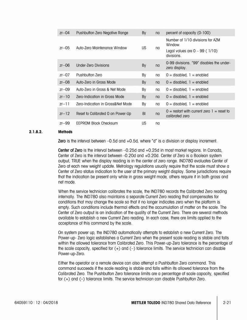
64059110 | 12 | 04/2018 METTLER TOLEDO IND780 Shared Data Reference 2-21
zr--04 Pushbutton Zero Negative Range By na percent of capacity (0-100)
zr--05 Auto-Zero Maintenance Window US na
Number of 1/10 divisions for AZM Window.
Legal values are 0 – 99 ( 1/10) divisions.
zr--06 Under-Zero Divisions By na 0-99 divisions. “99” disables the under-zero display.
zr--07 Pushbutton Zero By na 0 = disabled, 1 = enabled
zr--08 Auto-Zero in Gross Mode By na 0 = disabled, 1 = enabled
zr--09 Auto-Zero in Gross & Net Mode By na 0 = disabled, 1 = enabled
zr--10 Zero-Indication in Gross Mode By na 0 = disabled, 1 = enabled
zr--11 Zero-Indication in Gross&Net Mode By na 0 = disabled, 1 = enabled
zr--12 Reset to Calibrated 0 on Power-Up Bl na 0 = restart with current zero 1 = reset to calibrated zero
zr--99 EEPROM Block Checksum US na
2.1.8.2. Methods
Zero is the interval between –0.5d and +0.5d, where “d” is a division or display increment.
Center of Zero is the interval between –0.25d and +0.25d in most market regions. In Canada, Center of Zero is the interval between -0.20d and +0.20d. Center of Zero is a Boolean system output, TRUE when the display reading is in the center of zero range. IND780 evaluates Center of Zero at each new weight update. Metrology regulations usually require that the scale must show a Center of Zero status indication to the user at the primary weight display. Some jurisdictions require that the indication be present only while in gross weight mode, others require it in both gross and net mode.
When the service technician calibrates the scale, the IND780 records the Calibrated Zero reading internally. The IND780 also maintains a separate Current Zero reading that compensates for conditions that may change the scale so that it no longer indicates zero when the platform is empty. Such conditions include thermal effects and the accumulation of matter on the scale. The Center of Zero output is an indication of the quality of the Current Zero. There are several methods available to establish a new Current Zero reading. In each case, there are limits applied to the acceptance of this command by the scale.
On system power up, the IND780 automatically attempts to establish a new Current Zero. The Power-up- Zero logic establishes a Current Zero when the present scale reading is stable and falls within the allowed tolerance from Calibrated Zero. This Power-up-Zero tolerance is the percentage of the scale capacity, specified for (+) and (–) tolerance limits. The service technician can disable Power-up-Zero.
Either the operator or a remote device can also attempt a Pushbutton Zero command. This command succeeds if the scale reading is stable and falls within its allowed tolerance from the Calibrated Zero. The Pushbutton Zero tolerance limits are a percentage of scale capacity, specified for (+) and (–) tolerance limits. The service technician can disable Pushbutton Zero.
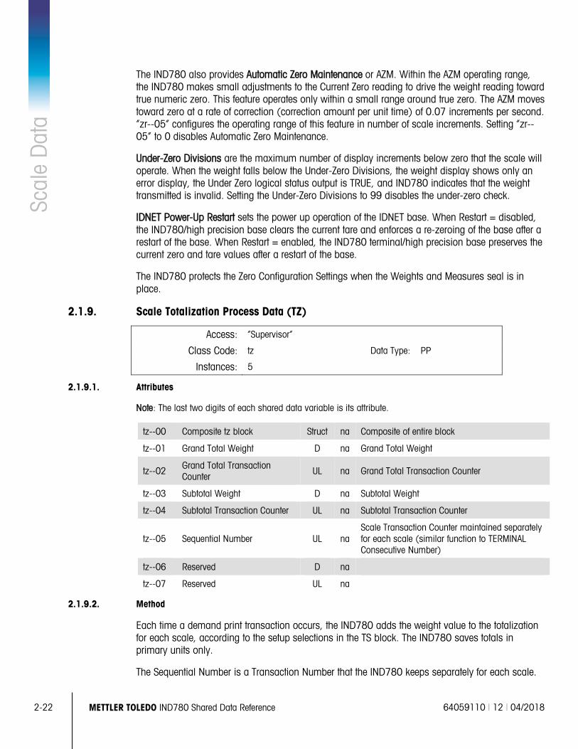
2-22 METTLER TOLEDO IND780 Shared Data Reference 64059110 | 12 | 04/2018
Scal
e D
ata
The IND780 also provides Automatic Zero Maintenance or AZM. Within the AZM operating range, the IND780 makes small adjustments to the Current Zero reading to drive the weight reading toward true numeric zero. This feature operates only within a small range around true zero. The AZM moves toward zero at a rate of correction (correction amount per unit time) of 0.07 increments per second. “zr--05” configures the operating range of this feature in number of scale increments. Setting “zr--05” to 0 disables Automatic Zero Maintenance.
Under-Zero Divisions are the maximum number of display increments below zero that the scale will operate. When the weight falls below the Under-Zero Divisions, the weight display shows only an error display, the Under Zero logical status output is TRUE, and IND780 indicates that the weight transmitted is invalid. Setting the Under-Zero Divisions to 99 disables the under-zero check.
IDNET Power-Up Restart sets the power up operation of the IDNET base. When Restart = disabled, the IND780/high precision base clears the current tare and enforces a re-zeroing of the base after a restart of the base. When Restart = enabled, the IND780 terminal/high precision base preserves the current zero and tare values after a restart of the base.
The IND780 protects the Zero Configuration Settings when the Weights and Measures seal is in place.
2.1.9. Scale Totalization Process Data (TZ)
Access: “Supervisor”
Class Code: tz Data Type: PP
Instances: 5
2.1.9.1. Attributes
Note: The last two digits of each shared data variable is its attribute.
tz--00 Composite tz block Struct na Composite of entire block
tz--01 Grand Total Weight D na Grand Total Weight
tz--02 Grand Total Transaction Counter
UL na Grand Total Transaction Counter
tz--03 Subtotal Weight D na Subtotal Weight
tz--04 Subtotal Transaction Counter UL na Subtotal Transaction Counter
tz--05 Sequential Number UL na Scale Transaction Counter maintained separately for each scale (similar function to TERMINAL Consecutive Number)
tz--06 Reserved D na
tz--07 Reserved UL na
2.1.9.2. Method
Each time a demand print transaction occurs, the IND780 adds the weight value to the totalization for each scale, according to the setup selections in the TS block. The IND780 saves totals in primary units only.
The Sequential Number is a Transaction Number that the IND780 keeps separately for each scale.
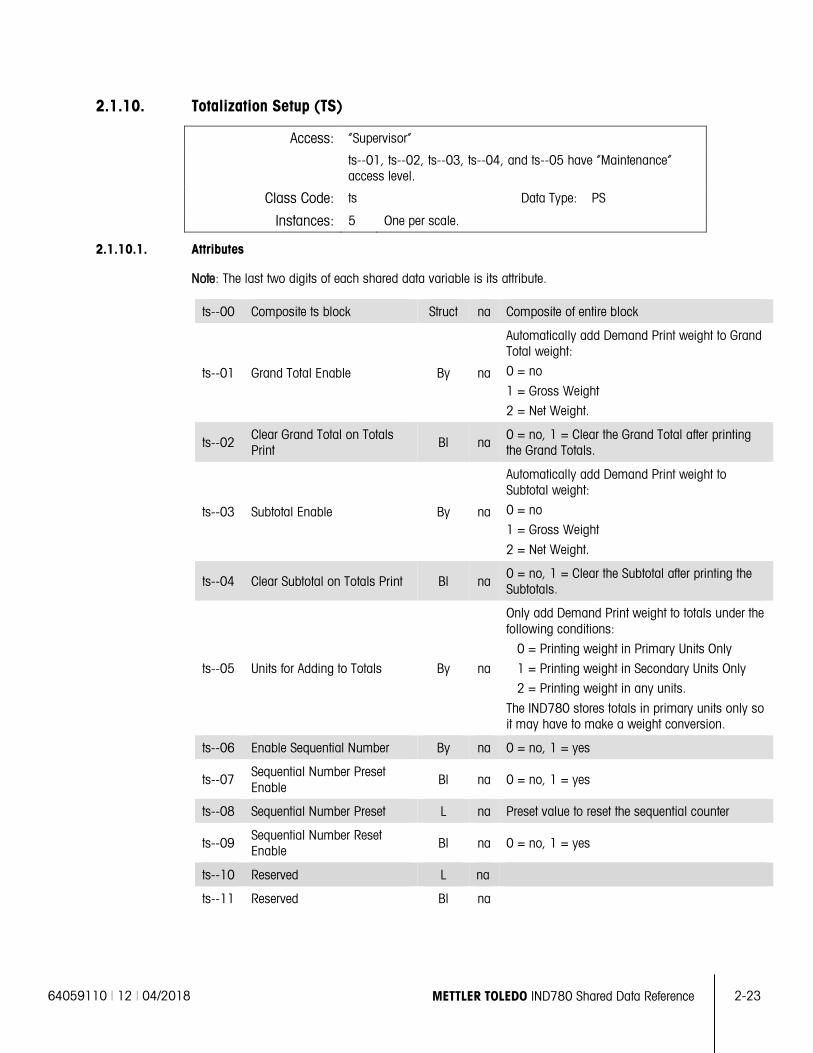
64059110 | 12 | 04/2018 METTLER TOLEDO IND780 Shared Data Reference 2-23
2.1.10. Totalization Setup (TS)
Access: “Supervisor”
ts--01, ts--02, ts--03, ts--04, and ts--05 have “Maintenance” access level.
Class Code: ts Data Type: PS
Instances: 5 One per scale.
2.1.10.1. Attributes
Note: The last two digits of each shared data variable is its attribute.
ts--00 Composite ts block Struct na Composite of entire block
ts--01 Grand Total Enable By na
Automatically add Demand Print weight to Grand Total weight:
0 = no
1 = Gross Weight
2 = Net Weight.
ts--02 Clear Grand Total on Totals Print Bl na
0 = no, 1 = Clear the Grand Total after printing the Grand Totals.
ts--03 Subtotal Enable By na
Automatically add Demand Print weight to Subtotal weight:
0 = no
1 = Gross Weight
2 = Net Weight.
ts--04 Clear Subtotal on Totals Print Bl na 0 = no, 1 = Clear the Subtotal after printing the Subtotals.
ts--05 Units for Adding to Totals By na
Only add Demand Print weight to totals under the following conditions:
0 = Printing weight in Primary Units Only
1 = Printing weight in Secondary Units Only
2 = Printing weight in any units.
The IND780 stores totals in primary units only so it may have to make a weight conversion.
ts--06 Enable Sequential Number By na 0 = no, 1 = yes
ts--07 Sequential Number Preset Enable
Bl na 0 = no, 1 = yes
ts--08 Sequential Number Preset L na Preset value to reset the sequential counter
ts--09 Sequential Number Reset Enable Bl na 0 = no, 1 = yes
ts--10 Reserved L na
ts--11 Reserved Bl na
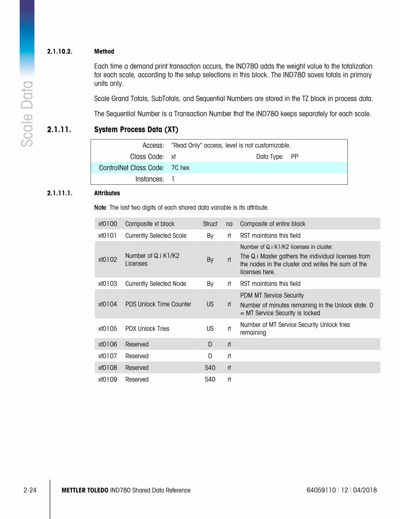
2-24 METTLER TOLEDO IND780 Shared Data Reference 64059110 | 12 | 04/2018
Scal
e D
ata
2.1.10.2. Method
Each time a demand print transaction occurs, the IND780 adds the weight value to the totalization for each scale, according to the setup selections in this block. The IND780 saves totals in primary units only.
Scale Grand Totals, SubTotals, and Sequential Numbers are stored in the TZ block in process data.
The Sequential Number is a Transaction Number that the IND780 keeps separately for each scale.
2.1.11. System Process Data (XT)
Access: “Read Only” access, level is not customizable.
Class Code: xt Data Type: PP
ControlNet Class Code: 7C hex
Instances: 1
2.1.11.1. Attributes
Note: The last two digits of each shared data variable is its attribute.
xt0100 Composite xt block Struct na Composite of entire block
xt0101 Currently Selected Scale By rt RST maintains this field
xt0102 Number of Q.i K1/K2 Licenses
By rt
Number of Q.i K1/K2 licenses in cluster.
The Q.i Master gathers the individual licenses from the nodes in the cluster and writes the sum of the licenses here.
xt0103 Currently Selected Node By rt RST maintains this field
xt0104 PDS Unlock Time Counter US rt PDM MT Service Security
Number of minutes remaining in the Unlock state. 0 = MT Service Security is locked
xt0105 PDX Unlock Tries US rt Number of MT Service Security Unlock tries remaining
xt0106 Reserved D rt
xt0107 Reserved D rt
xt0108 Reserved S40 rt
xt0109 Reserved S40 rt
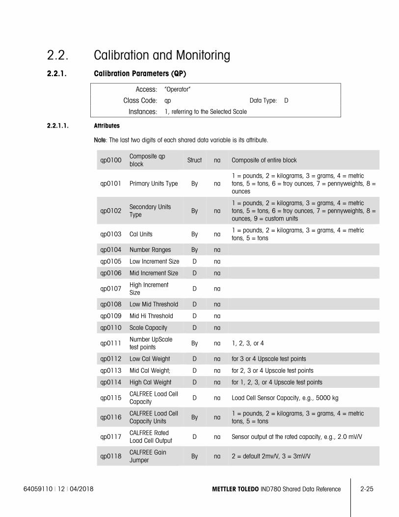
64059110 | 12 | 04/2018 METTLER TOLEDO IND780 Shared Data Reference 2-25
2.2. Calibration and Monitoring 2.2.1. Calibration Parameters (QP)
Access: “Operator”
Class Code: qp Data Type: D
Instances: 1, referring to the Selected Scale
2.2.1.1. Attributes
Note: The last two digits of each shared data variable is its attribute.
qp0100 Composite qp block
Struct na Composite of entire block
qp0101 Primary Units Type By na 1 = pounds, 2 = kilograms, 3 = grams, 4 = metric tons, 5 = tons, 6 = troy ounces, 7 = pennyweights, 8 = ounces
qp0102 Secondary Units Type By na
1 = pounds, 2 = kilograms, 3 = grams, 4 = metric tons, 5 = tons, 6 = troy ounces, 7 = pennyweights, 8 = ounces, 9 = custom units
qp0103 Cal Units By na 1 = pounds, 2 = kilograms, 3 = grams, 4 = metric tons, 5 = tons
qp0104 Number Ranges By na
qp0105 Low Increment Size D na
qp0106 Mid Increment Size D na
qp0107 High Increment Size
D na
qp0108 Low Mid Threshold D na
qp0109 Mid Hi Threshold D na
qp0110 Scale Capacity D na
qp0111 Number UpScale test points
By na 1, 2, 3, or 4
qp0112 Low Cal Weight D na for 3 or 4 Upscale test points
qp0113 Mid Cal Weight; D na for 2, 3 or 4 Upscale test points
qp0114 High Cal Weight D na for 1, 2, 3, or 4 Upscale test points
qp0115 CALFREE Load Cell Capacity D na Load Cell Sensor Capacity, e.g., 5000 kg
qp0116 CALFREE Load Cell Capacity Units
By na 1 = pounds, 2 = kilograms, 3 = grams, 4 = metric tons, 5 = tons
qp0117 CALFREE Rated Load Cell Output D na Sensor output at the rated capacity, e.g., 2.0 mV/V
qp0118 CALFREE Gain Jumper
By na 2 = default 2mv/V, 3 = 3mV/V
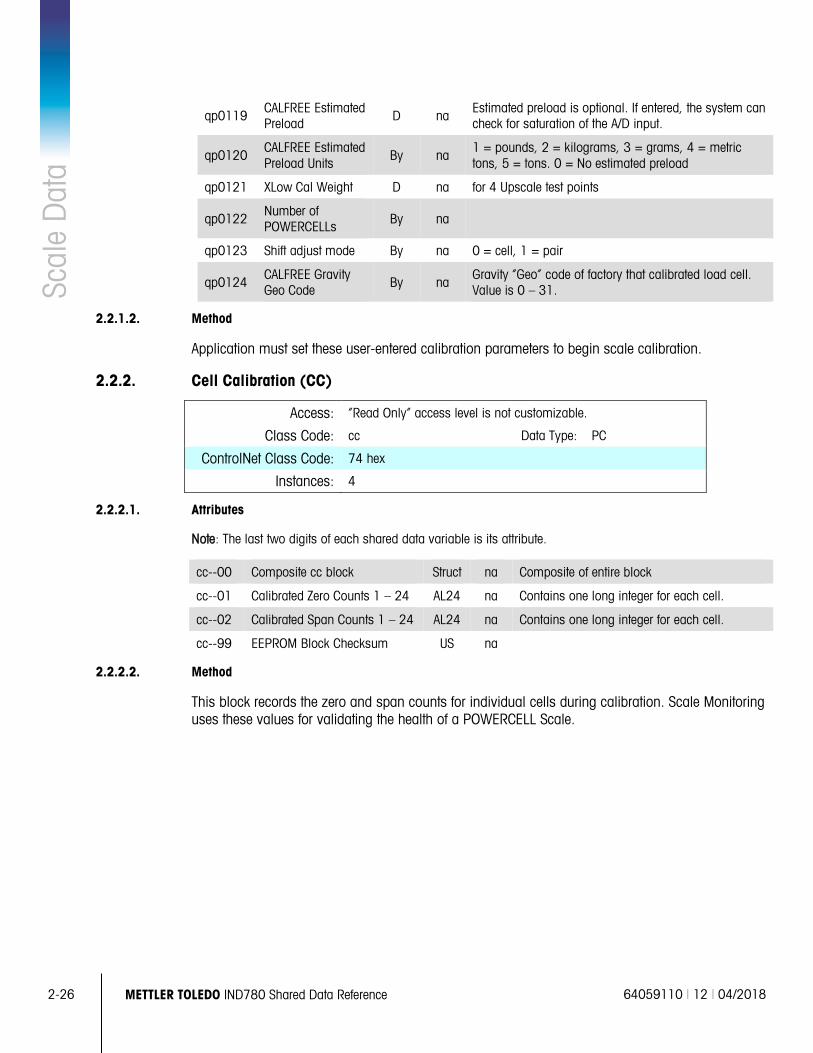
2-26 METTLER TOLEDO IND780 Shared Data Reference 64059110 | 12 | 04/2018
Scal
e D
ata
qp0119 CALFREE Estimated Preload D na
Estimated preload is optional. If entered, the system can check for saturation of the A/D input.
qp0120 CALFREE Estimated Preload Units
By na 1 = pounds, 2 = kilograms, 3 = grams, 4 = metric tons, 5 = tons. 0 = No estimated preload
qp0121 XLow Cal Weight D na for 4 Upscale test points
qp0122 Number of POWERCELLs By na
qp0123 Shift adjust mode By na 0 = cell, 1 = pair
qp0124 CALFREE Gravity Geo Code By na
Gravity “Geo” code of factory that calibrated load cell. Value is 0 – 31.
2.2.1.2. Method
Application must set these user-entered calibration parameters to begin scale calibration.
2.2.2. Cell Calibration (CC)
Access: “Read Only” access level is not customizable.
Class Code: cc Data Type: PC
ControlNet Class Code: 74 hex
Instances: 4
2.2.2.1. Attributes
Note: The last two digits of each shared data variable is its attribute.
cc--00 Composite cc block Struct na Composite of entire block
cc--01 Calibrated Zero Counts 1 – 24 AL24 na Contains one long integer for each cell.
cc--02 Calibrated Span Counts 1 – 24 AL24 na Contains one long integer for each cell.
cc--99 EEPROM Block Checksum US na
2.2.2.2. Method
This block records the zero and span counts for individual cells during calibration. Scale Monitoring uses these values for validating the health of a POWERCELL Scale.
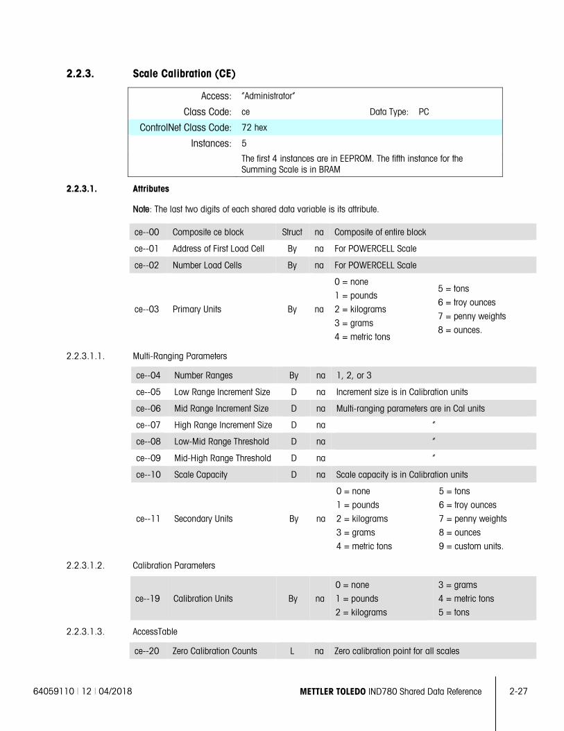
64059110 | 12 | 04/2018 METTLER TOLEDO IND780 Shared Data Reference 2-27
2.2.3. Scale Calibration (CE)
Access: “Administrator”
Class Code: ce Data Type: PC
ControlNet Class Code: 72 hex
Instances: 5
The first 4 instances are in EEPROM. The fifth instance for the Summing Scale is in BRAM
2.2.3.1. Attributes
Note: The last two digits of each shared data variable is its attribute.
ce--00 Composite ce block Struct na Composite of entire block
ce--01 Address of First Load Cell By na For POWERCELL Scale
ce--02 Number Load Cells By na For POWERCELL Scale
ce--03 Primary Units By na
0 = none
1 = pounds
2 = kilograms
3 = grams
4 = metric tons
5 = tons
6 = troy ounces
7 = penny weights
8 = ounces.
2.2.3.1.1. Multi-Ranging Parameters
ce--04 Number Ranges By na 1, 2, or 3
ce--05 Low Range Increment Size D na Increment size is in Calibration units
ce--06 Mid Range Increment Size D na Multi-ranging parameters are in Cal units
ce--07 High Range Increment Size D na “
ce--08 Low-Mid Range Threshold D na “
ce--09 Mid-High Range Threshold D na “
ce--10 Scale Capacity D na Scale capacity is in Calibration units
ce--11 Secondary Units By na
0 = none
1 = pounds
2 = kilograms
3 = grams
4 = metric tons
5 = tons
6 = troy ounces
7 = penny weights
8 = ounces
9 = custom units.
2.2.3.1.2. Calibration Parameters
ce--19 Calibration Units By na
0 = none
1 = pounds
2 = kilograms
3 = grams
4 = metric tons
5 = tons
2.2.3.1.3. AccessTable
ce--20 Zero Calibration Counts L na Zero calibration point for all scales
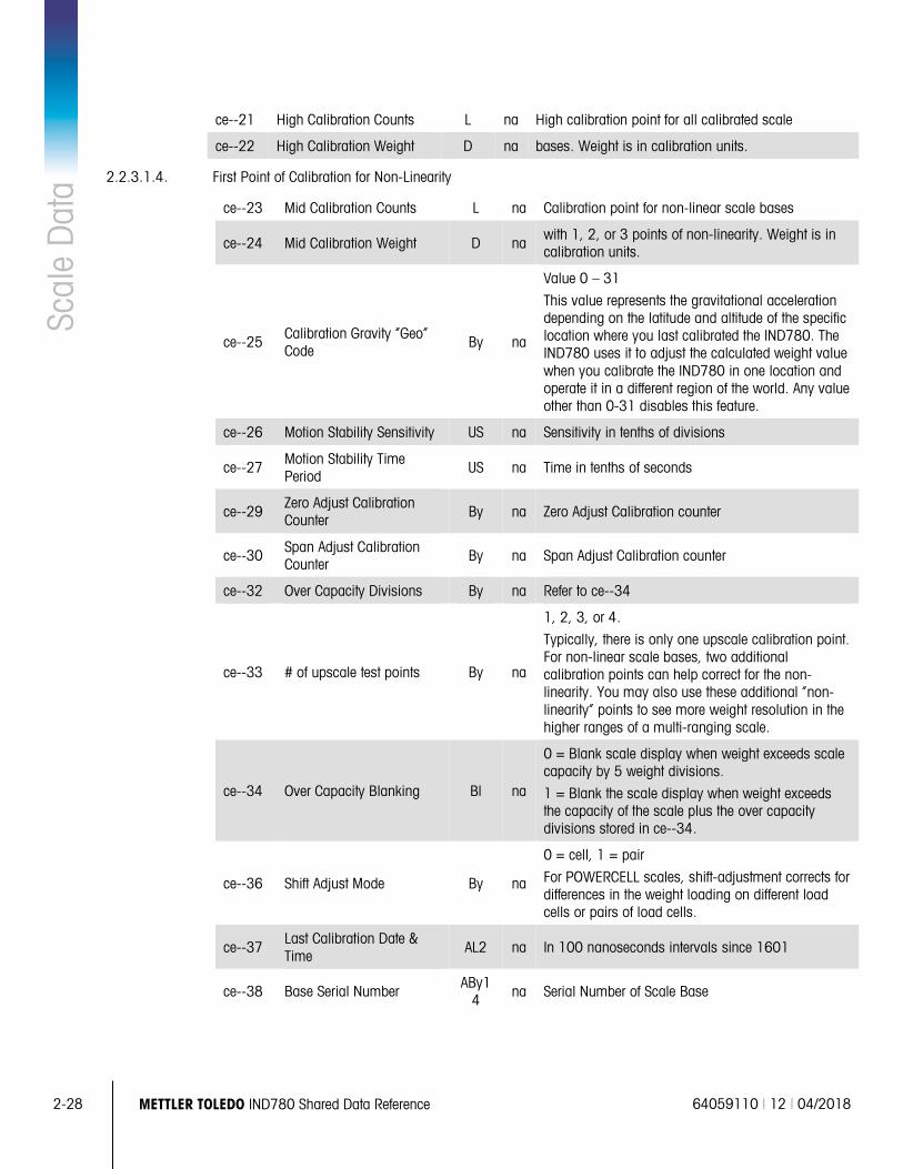
2-28 METTLER TOLEDO IND780 Shared Data Reference 64059110 | 12 | 04/2018
Scal
e D
ata
ce--21 High Calibration Counts L na High calibration point for all calibrated scale
ce--22 High Calibration Weight D na bases. Weight is in calibration units.
2.2.3.1.4. First Point of Calibration for Non-Linearity
ce--23 Mid Calibration Counts L na Calibration point for non-linear scale bases
ce--24 Mid Calibration Weight D na with 1, 2, or 3 points of non-linearity. Weight is in calibration units.
ce--25 Calibration Gravity “Geo” Code
By na
Value 0 – 31
This value represents the gravitational acceleration depending on the latitude and altitude of the specific location where you last calibrated the IND780. The IND780 uses it to adjust the calculated weight value when you calibrate the IND780 in one location and operate it in a different region of the world. Any value other than 0-31 disables this feature.
ce--26 Motion Stability Sensitivity US na Sensitivity in tenths of divisions
ce--27 Motion Stability Time Period
US na Time in tenths of seconds
ce--29 Zero Adjust Calibration Counter By na Zero Adjust Calibration counter
ce--30 Span Adjust Calibration Counter
By na Span Adjust Calibration counter
ce--32 Over Capacity Divisions By na Refer to ce--34
ce--33 # of upscale test points By na
1, 2, 3, or 4.
Typically, there is only one upscale calibration point. For non-linear scale bases, two additional calibration points can help correct for the non-linearity. You may also use these additional “non-linearity” points to see more weight resolution in the higher ranges of a multi-ranging scale.
ce--34 Over Capacity Blanking Bl na
0 = Blank scale display when weight exceeds scale capacity by 5 weight divisions.
1 = Blank the scale display when weight exceeds the capacity of the scale plus the over capacity divisions stored in ce--34.
ce--36 Shift Adjust Mode By na
0 = cell, 1 = pair
For POWERCELL scales, shift-adjustment corrects for differences in the weight loading on different load cells or pairs of load cells.
ce--37 Last Calibration Date & Time
AL2 na In 100 nanoseconds intervals since 1601
ce--38 Base Serial Number ABy1
4 na Serial Number of Scale Base
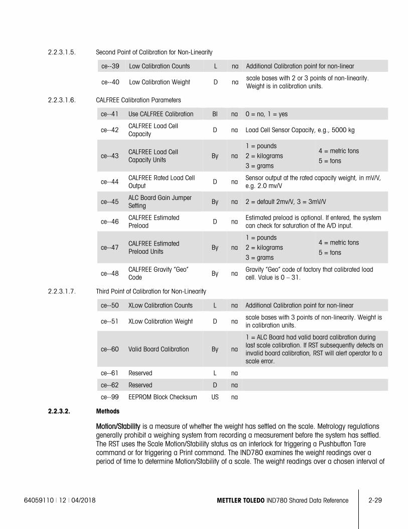
64059110 | 12 | 04/2018 METTLER TOLEDO IND780 Shared Data Reference 2-29
2.2.3.1.5. Second Point of Calibration for Non-Linearity
ce--39 Low Calibration Counts L na Additional Calibration point for non-linear
ce--40 Low Calibration Weight D na scale bases with 2 or 3 points of non-linearity. Weight is in calibration units.
2.2.3.1.6. CALFREE Calibration Parameters
ce--41 Use CALFREE Calibration Bl na 0 = no, 1 = yes
ce--42 CALFREE Load Cell Capacity
D na Load Cell Sensor Capacity, e.g., 5000 kg
ce--43 CALFREE Load Cell Capacity Units
By na
1 = pounds
2 = kilograms
3 = grams
4 = metric tons
5 = tons
ce--44 CALFREE Rated Load Cell Output
D na Sensor output at the rated capacity weight, in mV/V, e.g. 2.0 mv/V
ce--45 ALC Board Gain Jumper Setting By na 2 = default 2mv/V, 3 = 3mV/V
ce--46 CALFREE Estimated Preload
D na Estimated preload is optional. If entered, the system can check for saturation of the A/D input.
ce--47 CALFREE Estimated Preload Units
By na
1 = pounds
2 = kilograms
3 = grams
4 = metric tons
5 = tons
ce--48 CALFREE Gravity “Geo” Code By na
Gravity “Geo” code of factory that calibrated load cell. Value is 0 – 31.
2.2.3.1.7. Third Point of Calibration for Non-Linearity
ce--50 XLow Calibration Counts L na Additional Calibration point for non-linear
ce--51 XLow Calibration Weight D na scale bases with 3 points of non-linearity. Weight is in calibration units.
ce--60 Valid Board Calibration By na
1 = ALC Board had valid board calibration during last scale calibration. If RST subsequently detects an invalid board calibration, RST will alert operator to a scale error.
ce--61 Reserved L na
ce--62 Reserved D na
ce--99 EEPROM Block Checksum US na
2.2.3.2. Methods
Motion/Stability is a measure of whether the weight has settled on the scale. Metrology regulations generally prohibit a weighing system from recording a measurement before the system has settled. The RST uses the Scale Motion/Stability status as an interlock for triggering a Pushbutton Tare command or for triggering a Print command. The IND780 examines the weight readings over a period of time to determine Motion/Stability of a scale. The weight readings over a chosen interval of
2-30 METTLER TOLEDO IND780 Shared Data Reference 64059110 | 12 | 04/2018
Scal
e D
ata
time T must not differ from one another by more than the tolerance value V. The Service Technician can set the level for motion detection.
Over-Capacity Divisions are the number of display increments beyond the nominal scale capacity that the scale will operate. When the weight display exceeds the Over-Capacity Divisions, the weight display shows only an error display, the Over-Capacity logical status output is TRUE, and IND780 indicates that the weight transmitted is invalid. The Service Technician cannot disable the Over-Capacity checking.
The Units of Measure that the IND780 fully supports are:
• MKS – metric tons (t), kilograms (kg), grams (g)
• Avoirdupois – tons (ton), pounds (lb)
• troy ounces (toz), pennyweights (dwt), ounces (oz), custom units as secondary units only
The IND780 uses these fully supported units, as follows:
• Calibration Units define the units of calibration test weights.
• Primary Units are the preferred units of measure.
• Secondary Units are the alternate units when using units switching function. The IND780 can also display the Secondary units on the main display
With Multiple Range weighing, there can be up to three weighing ranges and each has a threshold. Each weighing range extends from zero to its range threshold. Each range has an associated increment size. The increment size and threshold value are larger for each successive weighing range from the lowest to highest ranges. The difference between the largest and smallest increment size is at most one decimal place. You manually set the increment sizes and thresholds in setup.
The IND780 only supports automatic selection of the “current weighing range”. When weight is increasing, the current weighing range proceeds from the lower range to the next higher range once the weight exceeds the range threshold. Switchover to the next higher range occurs at the range threshold. When weight is decreasing, the current weighing range returns from the current weighing range to the lowest range only when the weight falls within half-a-division of zero.
The IND780 weight display must clearly indicate the current weighing range. The terminal indicates weighing ranges 1, 2, and 3 respectively. The terminal maintains the same decimal point position in the Displayed Weight even when the current weighing range changes. There is at most one trailing, non-significant “0”. When right of the decimal point, the non-significant “0” must be in the third place to the right of the decimal point. You may take a Tare in any weighing range. The Displayed Weight and Printed Weight are always the same.
In Gross Mode, the IND780 determines the current weighing range by comparing the Fine Gross Weight to the range thresholds. If scale is within half-a-division of zero, the terminal returns to the lowest weighing range as the current weighing range. The IND780 calculates the Displayed Gross Weight by rounding the Fine Gross Weight to the nearest weight increment for the current weighing range.
In Net Mode, the terminal determines current weighing range by comparing the Fine Gross Weight to the range thresholds. If the scale is within half-a-division of zero for gross mode: the terminal returns to the lowest weighing range as the current weighing range. The IND780 terminal calculates

64059110 | 12 | 04/2018 METTLER TOLEDO IND780 Shared Data Reference 2-31
the Displayed Net Weight by rounding the Fine Net Weight to the nearest weight increment for the current weighing range. The IND780 calculates the Displayed Tare Weight by rounding the Fine Tare Weight to the nearest weight increment for the current weighing range. Displayed Gross Weight = Displayed Tare Weight + Displayed Net Weight.
Multi-Interval weighing rules only apply when the scale base is a high precision base. There can be up to three weighing intervals. Each weighing interval has a threshold. Each weighing interval extends from the threshold of the next lower interval to its threshold. Each interval has an associated increment size. The increment size and threshold value are larger for each successive weighing interval from the lowest to highest intervals. The high precision base sets the increment sizes and thresholds. The terminal only supports automatic selection of the “current weighing interval”. The IND780 display must clearly display the current weighing range. Displayed Weight and Printed Weight are always the same.
In Gross Mode, the IND780 determines the current weighing interval by comparing the Fine Gross Weight to the interval thresholds. The terminal calculates the Displayed Gross Weight by rounding the Fine Gross Weight to the nearest weight increment for the current weighing interval.
In Net Mode, the IND780 determines the “net weight current weighing interval” by comparing the Fine Net Weight to the interval thresholds. It calculates the Displayed Net Weight by rounding the Fine Net Weight to the nearest weight increment for the “net weight current weighing interval”. The terminal determines the “tare weight current weighing interval” by comparing the Fine Tare Weight to the interval thresholds. It calculates the Displayed Tare Weight by rounding the Fine Net Weight to the nearest weight increment for the “tare weight current weighing interval”. Displayed Gross Weight = Displayed Tare Weight + Displayed Net Weight.
2.2.3.2.1. Weights & Measures Compliance
Automatic Multi-Ranging is not compliant with the U.S. and Canadian regulations for Legal for Trade operation.
2.2.3.2.2. Calibration
The IND780 supports seven modes of scale calibration. These are:
• Standard, Two-Point Linear Calibration is the standard mode for calibrating the large majority of scales. You measure the scale counts at the zero weight and at a span weight of the scale.
• Three Point Calibration enables calibration of a scale with one intermediate point of non-linearity.
• Four Point Calibration enables calibration of a scale with two intermediate points of scale non-linearity.
• Five Point Calibration enables calibration of a scale with three intermediate points of scale non-linearity.
• Calculated Calibartion measures to zero weight of the scale and calculates the span value of the scale based on the weighing parameters of the load cell and the analog A-to-D circuitry.
• Zero Adjust Calibration adjusts only the zero value of the scale. It is valid for use with all modes of calibration.
• Span Adjust Calibration adjusts only the span value of the scale in a standard, two-point linear calibration.
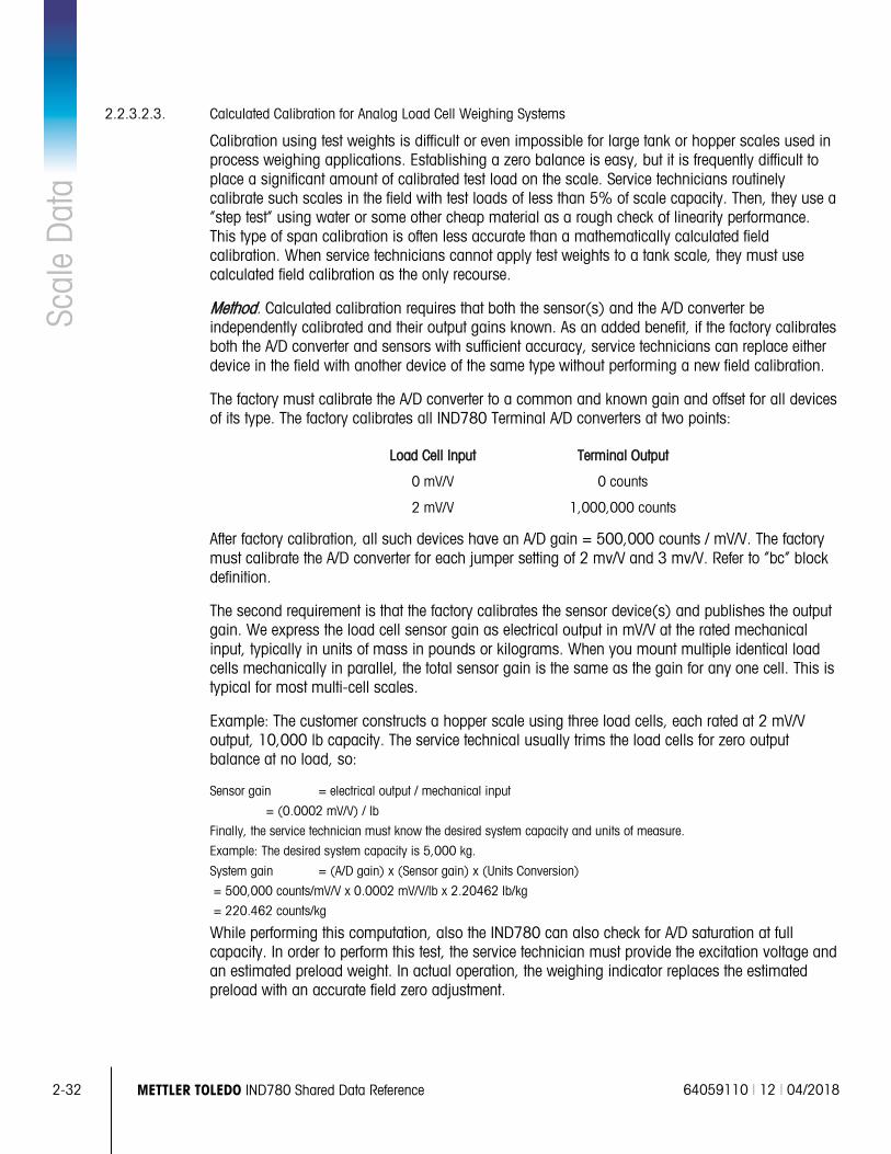
2-32 METTLER TOLEDO IND780 Shared Data Reference 64059110 | 12 | 04/2018
Scal
e D
ata
2.2.3.2.3. Calculated Calibration for Analog Load Cell Weighing Systems
Calibration using test weights is difficult or even impossible for large tank or hopper scales used in process weighing applications. Establishing a zero balance is easy, but it is frequently difficult to place a significant amount of calibrated test load on the scale. Service technicians routinely calibrate such scales in the field with test loads of less than 5% of scale capacity. Then, they use a “step test” using water or some other cheap material as a rough check of linearity performance. This type of span calibration is often less accurate than a mathematically calculated field calibration. When service technicians cannot apply test weights to a tank scale, they must use calculated field calibration as the only recourse.
Method. Calculated calibration requires that both the sensor(s) and the A/D converter be independently calibrated and their output gains known. As an added benefit, if the factory calibrates both the A/D converter and sensors with sufficient accuracy, service technicians can replace either device in the field with another device of the same type without performing a new field calibration.
The factory must calibrate the A/D converter to a common and known gain and offset for all devices of its type. The factory calibrates all IND780 Terminal A/D converters at two points:
Load Cell Input Terminal Output
0 mV/V 0 counts
2 mV/V 1,000,000 counts
After factory calibration, all such devices have an A/D gain = 500,000 counts / mV/V. The factory must calibrate the A/D converter for each jumper setting of 2 mv/V and 3 mv/V. Refer to “bc” block definition.
The second requirement is that the factory calibrates the sensor device(s) and publishes the output gain. We express the load cell sensor gain as electrical output in mV/V at the rated mechanical input, typically in units of mass in pounds or kilograms. When you mount multiple identical load cells mechanically in parallel, the total sensor gain is the same as the gain for any one cell. This is typical for most multi-cell scales.
Example: The customer constructs a hopper scale using three load cells, each rated at 2 mV/V output, 10,000 lb capacity. The service technical usually trims the load cells for zero output balance at no load, so:
Sensor gain = electrical output / mechanical input
= (0.0002 mV/V) / lb
Finally, the service technician must know the desired system capacity and units of measure.
Example: The desired system capacity is 5,000 kg.
System gain = (A/D gain) x (Sensor gain) x (Units Conversion)
= 500,000 counts/mV/V x 0.0002 mV/V/lb x 2.20462 lb/kg
= 220.462 counts/kg
While performing this computation, also the IND780 can also check for A/D saturation at full capacity. In order to perform this test, the service technician must provide the excitation voltage and an estimated preload weight. In actual operation, the weighing indicator replaces the estimated preload with an accurate field zero adjustment.
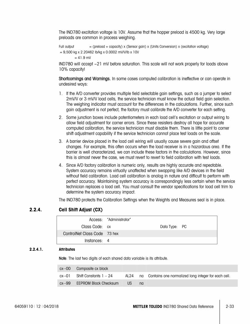
64059110 | 12 | 04/2018 METTLER TOLEDO IND780 Shared Data Reference 2-33
The IND780 excitation voltage is 10V. Assume that the hopper preload is 4500 kg. Very large preloads are common in process weighing.
Full output = (preload + capacity) x (Sensor gain) x (Units Conversion) x (excitation voltage)
= 9,500 kg x 2.20462 lb/kg x 0.0002 mV/V/lb x 10V
= 41.9 mV
IND780 will accept ~21 mV before saturation. This scale will not work properly for loads above 10% capacity!
Shortcomings and Warnings. In some cases computed calibration is ineffective or can operate in undesired ways:
1. If the A/D converter provides multiple field selectable gain settings, such as a jumper to select 2mV/V or 3 mV/V load cells, the service technician must know the actual field gain selection. The weighing indicator must account for the differences in the calculations. Further, since such gain adjustment is not perfect, the factory must calibrate the A/D converter for each setting.
2. Some junction boxes include potentiometers in each load cell’s excitation or output wiring to allow field adjustment for corner errors. Since these resisters destroy all hope for accurate computed calibration, the service technician must disable them. There is little point to corner shift adjustment capability if the service technician cannot place test loads on the scale.
3. A barrier device placed in the load cell wiring will usually cause severe gain and offset changes. For example, this often occurs when the load receiver is in a hazardous area. If the barrier is well characterized, we can include these factors in the calculations. However, since this is almost never the case, we must revert to revert to field calibration with test loads.
4. Since A/D factory calibration is numeric only, results are highly accurate and repeatable. System accuracy remains virtually unaffected when swapping like A/D devices in the field without field calibration. Load cell calibration is analog in nature and difficult to perform with perfect accuracy. Maintaining system accuracy is correspondingly less certain when the service technician replaces a load cell. You must consult the vendor specifications for load cell trim to determine the system accuracy impact.
The IND780 protects the Calibration Settings when the Weights and Measures seal is in place.
2.2.4. Cell Shift Adjust (CX)
Access: “Administrator”
Class Code: cx Data Type: PC
ControlNet Class Code 73 hex
Instances: 4
2.2.4.1. Attributes
Note: The last two digits of each shared data variable is its attribute.
cx--00 Composite cx block
cx--01 Shift Constants 1 – 24 AL24 na Contains one normalized long integer for each cell.
cx--99 EEPROM Block Checksum US na
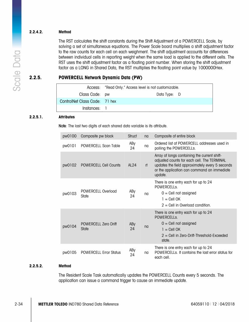
2-34 METTLER TOLEDO IND780 Shared Data Reference 64059110 | 12 | 04/2018
Scal
e D
ata
2.2.4.2. Method
The RST calculates the shift constants during the Shift Adjustment of a POWERCELL Scale, by solving a set of simultaneous equations. The Power Scale board multiplies a shift adjustment factor to the raw counts for each cell on each weighment. The shift adjustment accounts for differences between individual cells in reporting weight when the same load is applied to the different cells. The RST uses the shift adjustment factor as a floating point number. When storing the shift adjustment factor as a LONG in Shared Data, the RST multiplies the floating point value by 1000000Hex.
2.2.5. POWERCELL Network Dynamic Data (PW)
Access: “Read Only.” Access level is not customizable.
Class Code: pw Data Type: D
ControlNet Class Code: 71 hex
Instances: 1
2.2.5.1. Attributes
Note: The last two digits of each shared data variable is its attribute.
pw0100 Composite pw block Struct na Composite of entire block
pw0101 POWERCELL Scan Table ABy 24
na Ordered list of POWERCELL addresses used in polling the POWERCELLs.
pw0102 POWERCELL Cell Counts AL24 rt
Array of longs containing the current shift-adjusted counts for each cell. The TERMINAL updates the field approximately every 5 seconds or the application can command an immediate update.
pw0103 POWERCELL Overload State
ABy 24
na
There is one entry each for up to 24 POWERCELLs.
0 = Cell not assigned
1 = Cell OK
2 = Cell in Overload condition.
pw0104 POWERCELL Zero Drift State
ABy 24 na
There is one entry each for up to 24 POWERCELLs.
0 = Cell not assigned
1 = Cell OK
2 = Cell in Zero-Drift-Threshold-Exceeded state.
pw0105 POWERCELL Error Status ABy 24
na There is one entry each for up to 24 POWERCELLs. It contains the last error status for each cell.
2.2.5.2. Method
The Resident Scale Task automatically updates the POWERCELL Counts every 5 seconds. The application can issue a command trigger to cause an immediate update.
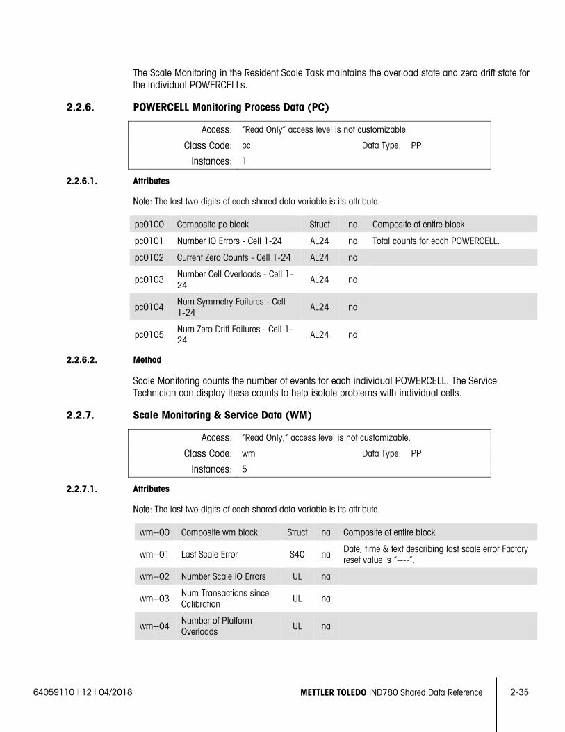
64059110 | 12 | 04/2018 METTLER TOLEDO IND780 Shared Data Reference 2-35
The Scale Monitoring in the Resident Scale Task maintains the overload state and zero drift state for the individual POWERCELLs.
2.2.6. POWERCELL Monitoring Process Data (PC)
Access: “Read Only” access level is not customizable.
Class Code: pc Data Type: PP
Instances: 1
2.2.6.1. Attributes
Note: The last two digits of each shared data variable is its attribute.
pc0100 Composite pc block Struct na Composite of entire block
pc0101 Number IO Errors - Cell 1-24 AL24 na Total counts for each POWERCELL.
pc0102 Current Zero Counts - Cell 1-24 AL24 na
pc0103 Number Cell Overloads - Cell 1-24
AL24 na
pc0104 Num Symmetry Failures - Cell 1-24
AL24 na
pc0105 Num Zero Drift Failures - Cell 1-24
AL24 na
2.2.6.2. Method
Scale Monitoring counts the number of events for each individual POWERCELL. The Service Technician can display these counts to help isolate problems with individual cells.
2.2.7. Scale Monitoring & Service Data (WM)
Access: “Read Only,” access level is not customizable.
Class Code: wm Data Type: PP
Instances: 5
2.2.7.1. Attributes
Note: The last two digits of each shared data variable is its attribute.
wm--00 Composite wm block Struct na Composite of entire block
wm--01 Last Scale Error S40 na Date, time & text describing last scale error Factory reset value is “----“.
wm--02 Number Scale IO Errors UL na
wm--03 Num Transactions since Calibration
UL na
wm--04 Number of Platform Overloads UL na
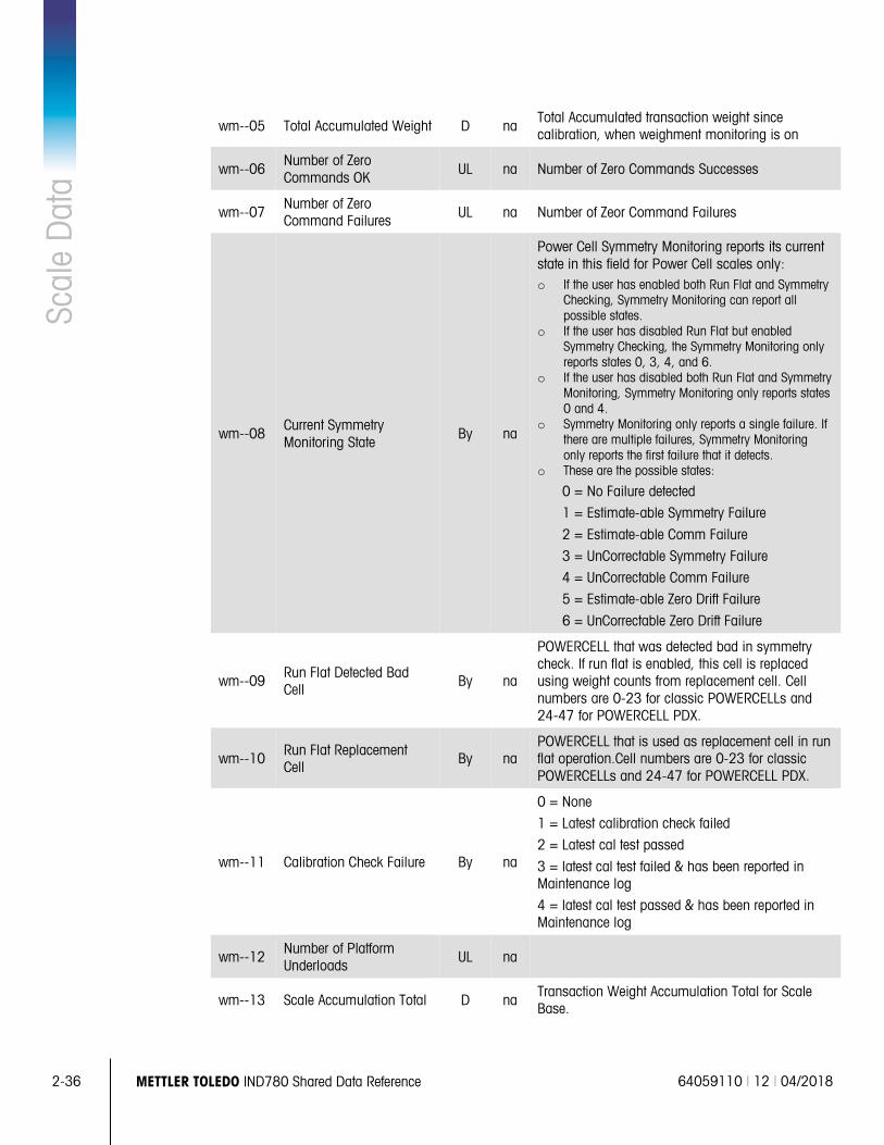
2-36 METTLER TOLEDO IND780 Shared Data Reference 64059110 | 12 | 04/2018
Scal
e D
ata
wm--05 Total Accumulated Weight D na Total Accumulated transaction weight since calibration, when weighment monitoring is on
wm--06 Number of Zero Commands OK
UL na Number of Zero Commands Successes
wm--07 Number of Zero Command Failures UL na Number of Zeor Command Failures
wm--08 Current Symmetry Monitoring State
By na
Power Cell Symmetry Monitoring reports its current state in this field for Power Cell scales only: o If the user has enabled both Run Flat and Symmetry
Checking, Symmetry Monitoring can report all possible states.
o If the user has disabled Run Flat but enabled Symmetry Checking, the Symmetry Monitoring only reports states 0, 3, 4, and 6.
o If the user has disabled both Run Flat and Symmetry Monitoring, Symmetry Monitoring only reports states 0 and 4.
o Symmetry Monitoring only reports a single failure. If there are multiple failures, Symmetry Monitoring only reports the first failure that it detects.
o These are the possible states:
0 = No Failure detected
1 = Estimate-able Symmetry Failure
2 = Estimate-able Comm Failure
3 = UnCorrectable Symmetry Failure
4 = UnCorrectable Comm Failure
5 = Estimate-able Zero Drift Failure
6 = UnCorrectable Zero Drift Failure
wm--09 Run Flat Detected Bad Cell
By na
POWERCELL that was detected bad in symmetry check. If run flat is enabled, this cell is replaced using weight counts from replacement cell. Cell numbers are 0-23 for classic POWERCELLs and 24-47 for POWERCELL PDX.
wm--10 Run Flat Replacement Cell
By na POWERCELL that is used as replacement cell in run flat operation.Cell numbers are 0-23 for classic POWERCELLs and 24-47 for POWERCELL PDX.
wm--11 Calibration Check Failure By na
0 = None
1 = Latest calibration check failed
2 = Latest cal test passed
3 = latest cal test failed & has been reported in Maintenance log
4 = latest cal test passed & has been reported in Maintenance log
wm--12 Number of Platform Underloads
UL na
wm--13 Scale Accumulation Total D na Transaction Weight Accumulation Total for Scale Base.
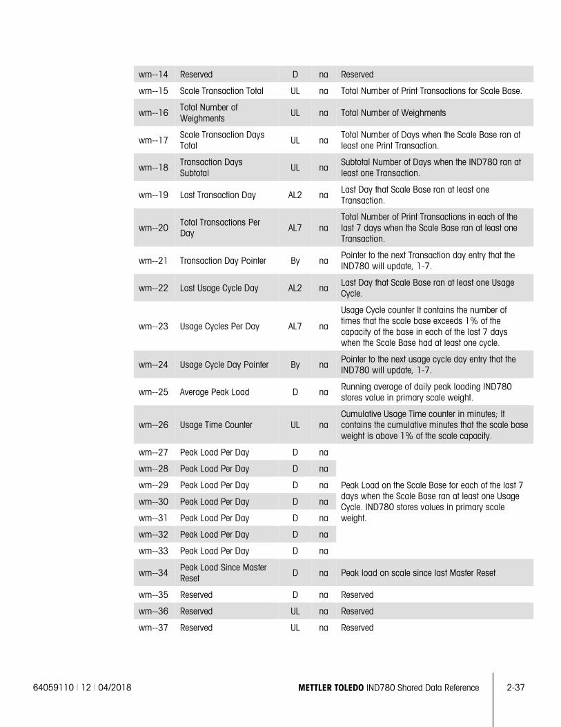
64059110 | 12 | 04/2018 METTLER TOLEDO IND780 Shared Data Reference 2-37
wm--14 Reserved D na Reserved
wm--15 Scale Transaction Total UL na Total Number of Print Transactions for Scale Base.
wm--16 Total Number of Weighments
UL na Total Number of Weighments
wm--17 Scale Transaction Days Total UL na
Total Number of Days when the Scale Base ran at least one Print Transaction.
wm--18 Transaction Days Subtotal
UL na Subtotal Number of Days when the IND780 ran at least one Transaction.
wm--19 Last Transaction Day AL2 na Last Day that Scale Base ran at least one Transaction.
wm--20 Total Transactions Per Day AL7 na
Total Number of Print Transactions in each of the last 7 days when the Scale Base ran at least one Transaction.
wm--21 Transaction Day Pointer By na Pointer to the next Transaction day entry that the IND780 will update, 1-7.
wm--22 Last Usage Cycle Day AL2 na Last Day that Scale Base ran at least one Usage Cycle.
wm--23 Usage Cycles Per Day AL7 na
Usage Cycle counter It contains the number of times that the scale base exceeds 1% of the capacity of the base in each of the last 7 days when the Scale Base had at least one cycle.
wm--24 Usage Cycle Day Pointer By na Pointer to the next usage cycle day entry that the IND780 will update, 1-7.
wm--25 Average Peak Load D na Running average of daily peak loading IND780 stores value in primary scale weight.
wm--26 Usage Time Counter UL na Cumulative Usage Time counter in minutes; It contains the cumulative minutes that the scale base weight is above 1% of the scale capacity.
wm--27 Peak Load Per Day D na
Peak Load on the Scale Base for each of the last 7 days when the Scale Base ran at least one Usage Cycle. IND780 stores values in primary scale weight.
wm--28 Peak Load Per Day D na
wm--29 Peak Load Per Day D na
wm--30 Peak Load Per Day D na
wm--31 Peak Load Per Day D na
wm--32 Peak Load Per Day D na
wm--33 Peak Load Per Day D na
wm--34 Peak Load Since Master Reset
D na Peak load on scale since last Master Reset
wm--35 Reserved D na Reserved
wm--36 Reserved UL na Reserved
wm--37 Reserved UL na Reserved
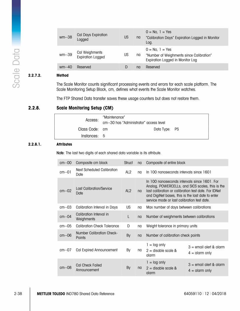
2-38 METTLER TOLEDO IND780 Shared Data Reference 64059110 | 12 | 04/2018
Scal
e D
ata
wm--38 Cal Days Expiration Logged US na
0 = No, 1 = Yes
“Calibration Days” Expiration Logged in Monitor Log.
wm--39 Cal Weighments Expiration Logged
US na 0 = No, 1 = Yes
“Number of Weighments since Calibration” Expiration Logged in Monitor Log
wm--40 Reserved D na Reserved
2.2.7.2. Method
The Scale Monitor counts significant processing events and errors for each scale platform. The Scale Monitoring Setup Block, cm, defines what events the Scale Monitor watches.
The FTP Shared Data transfer saves these usage counters but does not restore them.
2.2.8. Scale Monitoring Setup (CM)
Access: “Maintenance” cm--30 has “Administrator” access level
Class Code: cm Data Type: PS
Instances: 5
2.2.8.1. Attributes
Note: The last two digits of each shared data variable is its attribute.
cm--00 Composite cm block Struct na Composite of entire block
cm--01 Next Scheduled Calibration Date
AL2 na In 100 nanoseconds intervals since 1601
cm--02 Last Calibration/Service Date
AL2 na
In 100 nanoseconds intervals since 1601. For Analog, POWERCELLs, and SICS scales, this is the last calibration or calibration test date. For IDNet and DigiNet bases, this is the last date to enter service mode or last calibration test date.
cm--03 Calibration Interval in Days US na Max number of days between calibrations
cm--04 Calibration Interval in Weighments
L na Number of weighments between calibrations
cm--05 Calibration Check Tolerance D na Weight tolerance in primary units
cm--06 Number Calibration Check-Points By na Number of calibration check points
cm--07 Cal Expired Announcement By na 1 = log only
2 = disable scale & alarm
3 = email alert & alarm
4 = alarm only
cm--08 Cal Check Failed Announcement
By na 1 = log only
2 = disable scale & alarm
3 = email alert & alarm
4 = alarm only
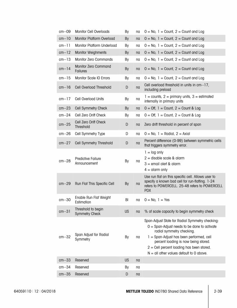
64059110 | 12 | 04/2018 METTLER TOLEDO IND780 Shared Data Reference 2-39
cm--09 Monitor Cell Overloads By na 0 = No, 1 = Count, 2 = Count and Log
cm--10 Monitor Platform Overload By na 0 = No, 1 = Count, 2 = Count and Log
cm--11 Monitor Platform Underload By na 0 = No, 1 = Count, 2 = Count and Log
cm--12 Monitor Weighments By na 0 = No, 1 = Count, 2 = Count and Log
cm--13 Monitor Zero Commands By na 0 = No, 1 = Count, 2 = Count and Log
cm--14 Monitor Zero Command Failures By na 0 = No, 1 = Count, 2 = Count and Log
cm--15 Monitor Scale IO Errors By na 0 = No, 1 = Count, 2 = Count and Log
cm--16 Cell Overload Threshold D na Cell overload threshold in units in cm--17, including preload
cm--17 Cell Overload Units By na 1 = counts, 2 = primary units, 3 = estimated internally in primary units
cm--23 Cell Symmetry Check By na 0 = Off, 1 = Count, 2 = Count & Log
cm--24 Cell Zero Drift Check By na 0 = Off, 1 = Count, 2 = Count & Log
cm--25 Cell Zero Drift Check Threshold
D na Zero drift threshold in percent of span
cm--26 Cell Symmetry Type D na 0 = No, 1 = Radial, 2 = Axial
cm--27 Cell Symmetry Threshold D na Percent difference (0-99) between symmetric cells that triggers symmetry error.
cm--28 Predictive Failure Announcement
By na
1 = log only
2 = disable scale & alarm
3 = email alert & alarm
4 = alarm only
cm--29 Run Flat This Specific Cell By na
Use run flat on this specific cell. Allows user to specify a known bad cell for run-flatting. 1-24 refers to POWERCELL. 25-48 refers to POWERCELL PDX
cm--30 Enable Run Flat Weight Estimation
Bl na 0 = No, 1 = Yes
cm--31 Threshold to begin Symmetry Check US na % of scale capacity to begin symmetry check
cm--32 Span Adjust for Radial Symmetry
By na
Span-Adjust State for Radial Symmetry checking:
0 = Span-Adjust needs to be done to activate radial symmetry checking.
1 = Span-Adjust has been performed, cell percent loading is now being stored.
2 = Cell percent loading has been stored.
N = all other values default to 0 above.
cm--33 Reserved US na
cm--34 Reserved By na
cm--35 Reserved D na
2-40 METTLER TOLEDO IND780 Shared Data Reference 64059110 | 12 | 04/2018
Scal
e D
ata
2.2.8.2. Methods
2.2.8.2.1. Calibration Checking
The IND780 can enforce Calibration Checking within a certain interval. The Service Technician specifies the interval either in number of days or weighments. Calibration Checking helps the Service Technician test and certify the accuracy of the scale. The scale must weigh test weights within a specified tolerance in the specified number of locations on the scale platform. The Service Technician can certify the scale “as found” if he knows that the scale is weighing accurately. The IND780 prints a receipt of the Calibration Check procedure, and saves the results in the Calibration Check Log. The IND780 can disable the scale, issue a local alert, or email a general alert when the calibration check fails.
2.2.8.2.2. Scale Monitoring
The IND780 can monitor the usage of a scale and record statistics of its use. The Service Technician can set the IND780 to record every occurrence in the Monitor Log File or simply to keep a count of the specific usages. The Monitor Log is a circular file that records the latest occurrences. These records can give the Service Technician knowledge about the health of the scale system. The IND780 can record the weighments, the errors, the zero attempts, and the overloads.
2.2.8.2.3. Predictive Failure
The IND780 can automatically confirm the fitness of the load cells in POWERCELL scales. To do this, it compares the current load cell readings to the readings established when the Scale Technician last calibrated the scale. A significant shift in the load cell output may indicate either current or impending load cell failure. The IND780 has selectable levels of alerting the scale operator or scale technician when it detects a potential fault. The IND780 Display and Web Pages enable you to view the zero, span, and current counts for individual cells attached to the IND780 indicator.
2.2.8.2.4. Cell Zero-Drift Checking
If a scale periodically returns to zero, the IND780 automatically tests the individual load cell readings when the scale is at zero. If the current zero reading does not match the calibrated zero values within a tolerance, it is likely there is a fault condition. However, the IND780 cannot verify zero for many scales. For example, hopper scales may accumulate material on the hopper surfaces; In storage tanks, the scale may never be at zero.
2.2.8.2.5. Cell Symmetry Checking
If a POWERCELL Scale has individual load cells arranged in a logical symmetry, the Scale Monitoring can periodically cross-check the fitness of the individual load cells. The IND780 determines the likely reading for an individual cell by using the readings from one or more cells that are symmetrical to it. If the readings do not match within a tolerance, a fault condition is likely. Here are the possible types of symmetry:
• Left-right symmetry. A railroad track scale or vehicle scale is an example of left-right pair symmetry. The scale has two or more pairs of load cells. Since each cell of a pair usually sees the same loading pattern, the Scale Monitoring can cross-check individual readings from the pair.
• Radial symmetry. Cylindrical tank or hopper scales often have identical net weight loading on all load cells, though they may have an off center dead load due to the mounting of the

64059110 | 12 | 04/2018 METTLER TOLEDO IND780 Shared Data Reference 2-41
discharge feeder machinery. This symmetry is especially strong if the scale is weighing liquid or powder materials. The IND780 can cross check-readings from all the individual cells. The user must perform a Span-Adjust with a load to enable the radial symmetry checking. The load should be at least 10% of the tank capacity. The Span-Adjust enables the Radial Symmetry checking to calculate load percentages on each load cell.
• No symmetry. A floor scale or an overhead monorail scale is a good example. A load could be placed at any location, and any single cell could see all, some, or none of the load. The IND780 Scale Monitoring cannot cross check readings from the individual cells in these scales.
2.2.8.2.6. Run Flat
Run Flat is an emergency technique for weighing after a load cell in a POWERCELL Scale has failed. The IND780 estimates the weight on a platform by using the weight from other load cells that are in a symmetrical relationship with the failed cell. The control panel clearly displays the weight as an estimated weight.
2.2.9. PDX Cell Dynamic Shared Data (PY)
Access: “Read Only” Access level is not customizable
Class Code: py Data Type: D
ControlNet Class Code: 9D hex
Instances: 1
2.2.9.1. Attributes
Note: The last two digits of each shared data variable is its attribute.
py0100 Composite py block struct na Composite of entire block
py0101 PDX Cell Scan Table ABy 24 na Ordered list of PDX cell addresses used in polling the PDX cells.
py0102 PDX Cell Counts AL24 rt
Array of longs containing the current shift-adjusted counts for each cell. The IND780 updates the field approximately every 5 seconds, or the application can command an immediate update.
py0103 PDX Overload State ABy 24 na One entry each for up to 24 PDX cells. 0 = Cell not assigned, 1 = Cell OK, 2 = Cell in Overload condition
py0104 PDX Zero Drift State ABy 24 na One entry each for up to 24 PDX cells. 0 = Cell not assigned, 1 = Cell OK, 2 = Cell in Zero-Drift-Threshold-Exceeded state
py0105 PDX Error Status ABy 24 na One entry each for up to 24 PDX cells. Contains the last error status for each cell.
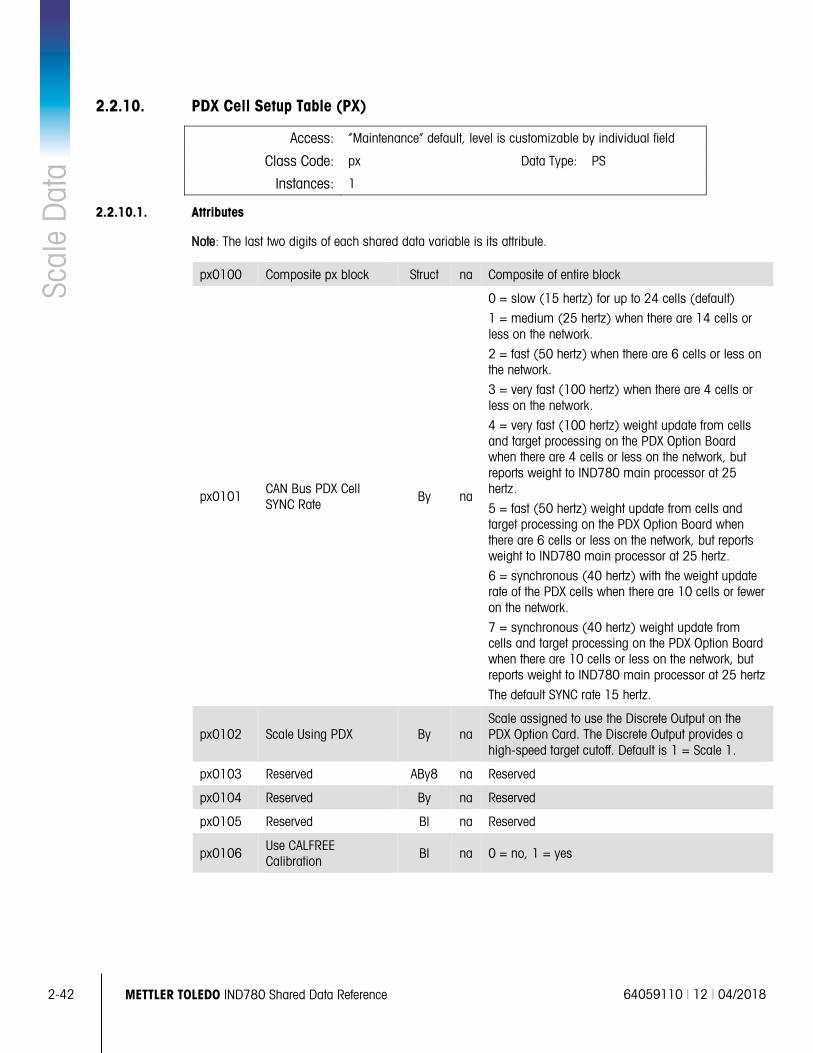
2-42 METTLER TOLEDO IND780 Shared Data Reference 64059110 | 12 | 04/2018
Scal
e D
ata
2.2.10. PDX Cell Setup Table (PX)
Access: “Maintenance” default, level is customizable by individual field
Class Code: px Data Type: PS
Instances: 1
2.2.10.1. Attributes
Note: The last two digits of each shared data variable is its attribute.
px0100 Composite px block Struct na Composite of entire block
px0101 CAN Bus PDX Cell SYNC Rate
By na
0 = slow (15 hertz) for up to 24 cells (default)
1 = medium (25 hertz) when there are 14 cells or less on the network.
2 = fast (50 hertz) when there are 6 cells or less on the network.
3 = very fast (100 hertz) when there are 4 cells or less on the network.
4 = very fast (100 hertz) weight update from cells and target processing on the PDX Option Board when there are 4 cells or less on the network, but reports weight to IND780 main processor at 25 hertz.
5 = fast (50 hertz) weight update from cells and target processing on the PDX Option Board when there are 6 cells or less on the network, but reports weight to IND780 main processor at 25 hertz.
6 = synchronous (40 hertz) with the weight update rate of the PDX cells when there are 10 cells or fewer on the network.
7 = synchronous (40 hertz) weight update from cells and target processing on the PDX Option Board when there are 10 cells or less on the network, but reports weight to IND780 main processor at 25 hertz
The default SYNC rate 15 hertz.
px0102 Scale Using PDX By na Scale assigned to use the Discrete Output on the PDX Option Card. The Discrete Output provides a high-speed target cutoff. Default is 1 = Scale 1.
px0103 Reserved ABy8 na Reserved
px0104 Reserved By na Reserved
px0105 Reserved Bl na Reserved
px0106 Use CALFREE Calibration
Bl na 0 = no, 1 = yes
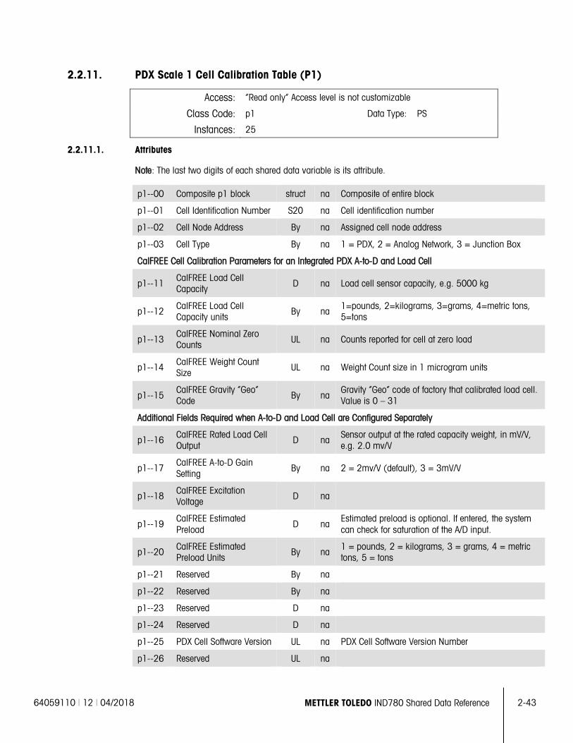
64059110 | 12 | 04/2018 METTLER TOLEDO IND780 Shared Data Reference 2-43
2.2.11. PDX Scale 1 Cell Calibration Table (P1)
Access: “Read only” Access level is not customizable
Class Code: p1 Data Type: PS
Instances: 25
2.2.11.1. Attributes
Note: The last two digits of each shared data variable is its attribute.
p1--00 Composite p1 block struct na Composite of entire block
p1--01 Cell Identification Number S20 na Cell identification number
p1--02 Cell Node Address By na Assigned cell node address
p1--03 Cell Type By na 1 = PDX, 2 = Analog Network, 3 = Junction Box
CalFREE Cell Calibration Parameters for an Integrated PDX A-to-D and Load Cell
p1--11 CalFREE Load Cell Capacity D na Load cell sensor capacity, e.g. 5000 kg
p1--12 CalFREE Load Cell Capacity units
By na 1=pounds, 2=kilograms, 3=grams, 4=metric tons, 5=tons
p1--13 CalFREE Nominal Zero Counts UL na Counts reported for cell at zero load
p1--14 CalFREE Weight Count Size
UL na Weight Count size in 1 microgram units
p1--15 CalFREE Gravity “Geo” Code By na
Gravity “Geo” code of factory that calibrated load cell. Value is 0 – 31
Additional Fields Required when A-to-D and Load Cell are Configured Separately
p1--16 CalFREE Rated Load Cell Output
D na Sensor output at the rated capacity weight, in mV/V, e.g. 2.0 mv/V
p1--17 CalFREE A-to-D Gain Setting
By na 2 = 2mv/V (default), 3 = 3mV/V
p1--18 CalFREE Excitation Voltage
D na
p1--19 CalFREE Estimated Preload
D na Estimated preload is optional. If entered, the system can check for saturation of the A/D input.
p1--20 CalFREE Estimated Preload Units
By na 1 = pounds, 2 = kilograms, 3 = grams, 4 = metric tons, 5 = tons
p1--21 Reserved By na
p1--22 Reserved By na
p1--23 Reserved D na
p1--24 Reserved D na
p1--25 PDX Cell Software Version UL na PDX Cell Software Version Number
p1--26 Reserved UL na
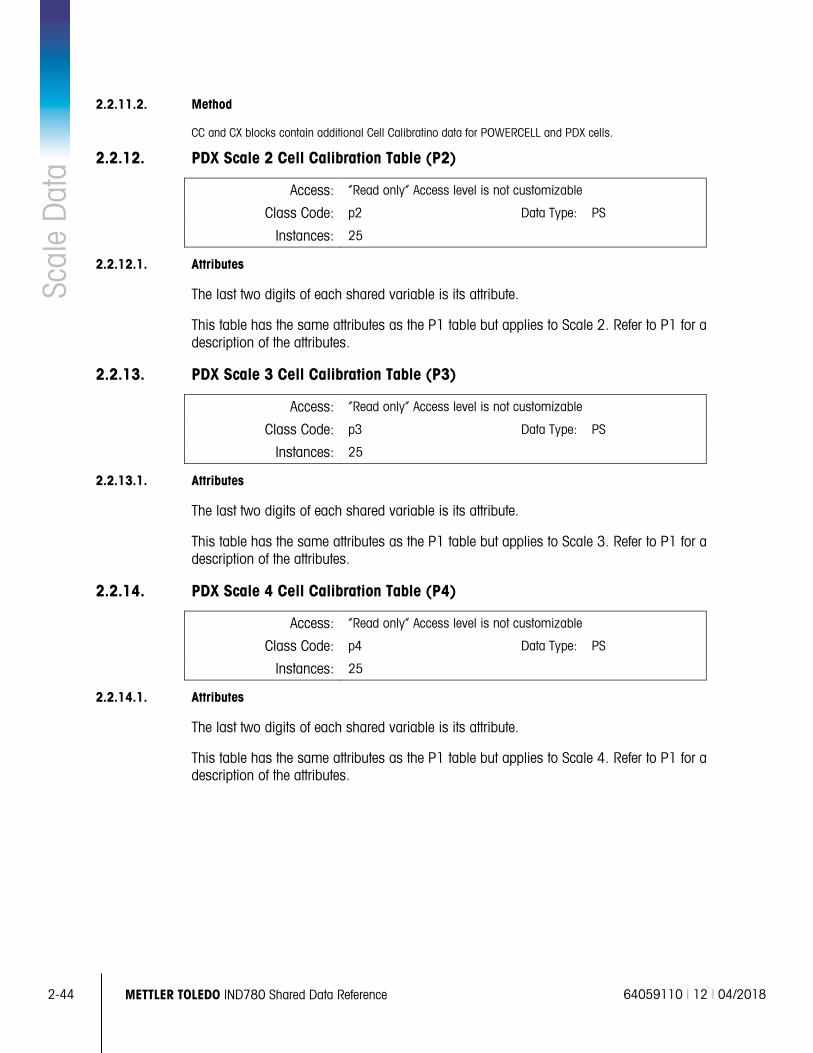
2-44 METTLER TOLEDO IND780 Shared Data Reference 64059110 | 12 | 04/2018
Scal
e D
ata
2.2.11.2. Method
CC and CX blocks contain additional Cell Calibratino data for POWERCELL and PDX cells.
2.2.12. PDX Scale 2 Cell Calibration Table (P2)
Access: “Read only” Access level is not customizable
Class Code: p2 Data Type: PS
Instances: 25
2.2.12.1. Attributes
The last two digits of each shared variable is its attribute.
This table has the same attributes as the P1 table but applies to Scale 2. Refer to P1 for a description of the attributes.
2.2.13. PDX Scale 3 Cell Calibration Table (P3)
Access: “Read only” Access level is not customizable
Class Code: p3 Data Type: PS
Instances: 25
2.2.13.1. Attributes
The last two digits of each shared variable is its attribute.
This table has the same attributes as the P1 table but applies to Scale 3. Refer to P1 for a description of the attributes.
2.2.14. PDX Scale 4 Cell Calibration Table (P4)
Access: “Read only” Access level is not customizable
Class Code: p4 Data Type: PS
Instances: 25
2.2.14.1. Attributes
The last two digits of each shared variable is its attribute.
This table has the same attributes as the P1 table but applies to Scale 4. Refer to P1 for a description of the attributes.
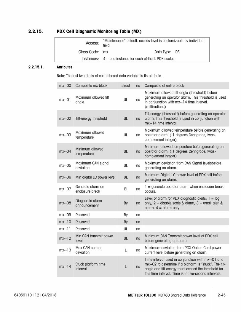
64059110 | 12 | 04/2018 METTLER TOLEDO IND780 Shared Data Reference 2-45
2.2.15. PDX Cell Diagnostic Monitoring Table (MX)
Access: “Maintenance” default, access level is customizable by individual field
Class Code: mx Data Type: PS
Instances: 4 – one instance for each of the 4 PDX scales
2.2.15.1. Attributes
Note: The last two digits of each shared data variable is its attribute.
mx--00 Composite mx block struct na Composite of entire block
mx--01 Maximum allowed tilt angle
UL na
Maximum allowed tilt-angle (threshold) before generating an operator alarm. This threshold is used in conjunction with mx--14 time interval. (milliradians)
mx--02 Tilt-energy threshold UL na Tilt-energy (threshold) before generating an operator alarm. This threshold is used in conjunction with mx--14 time interval.
mx--03 Maximum allowed temperature
UL na Maximum allowed temperature before generating an operator alarm. (.1 degrees Centigrade, twos-complement integer)
mx--04 Minimum allowed temperature
UL na Minimum allowed temperature beforegenerating an operator alarm. (.1 degrees Centigrade, twos-complement integer)
mx--05 Maximum CAN signal deviation
UL na Maximum deviation from CAN Signal levelsbefore generating an alarm.
mx--06 Min digital LC power level UL na Minimum Digital LC power level at PDX cell before generating an alarm.
mx--07 Generate alarm on enclosure break
Bl na 1 = generate operator alarm when enclosure break occurs.
mx--08 Diagnostic alarm announcement
By na Level of alarm for PDX diagnostic alerts: 1 = log only, 2 = disable scale & alarm, 3 = email alert & alarm, 4 = alarm only
mx--09 Reserved By na
mx--10 Reserved By na
mx--11 Reserved UL na
mx--12 Min CAN transmit power level
UL na Minimum CAN Transmit power level at PDX cell before generating an alarm.
mx--13 Max CAN current deviation L na
Maximum deviation from PDX Option Card power current level before generating an alarm.
mx--14 Stuck platform time interval L na
Time interval used in conjunction with mx--01 and mx--02 to determine if a platform is “stuck”. The tilt-angle and tilt-energy must exceed the threshold for this time interval. Time is in five-second intervals.
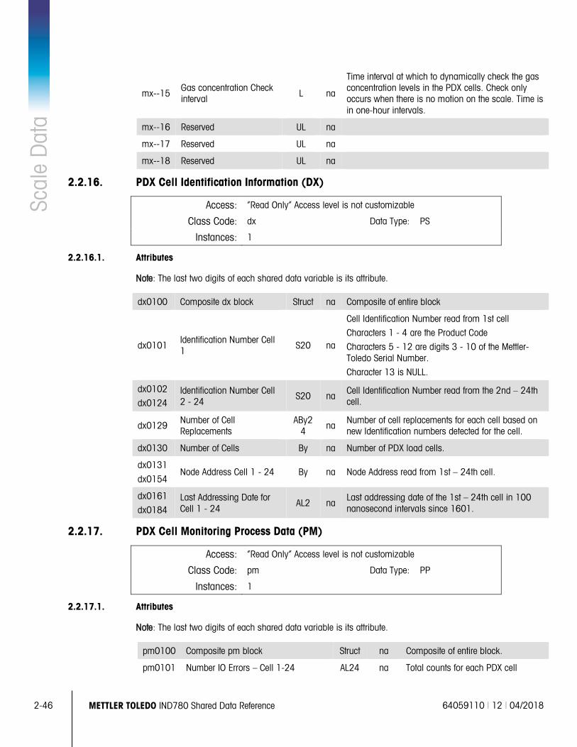
2-46 METTLER TOLEDO IND780 Shared Data Reference 64059110 | 12 | 04/2018
Scal
e D
ata
mx--15 Gas concentration Check interval L na
Time interval at which to dynamically check the gas concentration levels in the PDX cells. Check only occurs when there is no motion on the scale. Time is in one-hour intervals.
mx--16 Reserved UL na
mx--17 Reserved UL na
mx--18 Reserved UL na
2.2.16. PDX Cell Identification Information (DX)
Access: “Read Only” Access level is not customizable
Class Code: dx Data Type: PS
Instances: 1
2.2.16.1. Attributes
Note: The last two digits of each shared data variable is its attribute.
dx0100 Composite dx block Struct na Composite of entire block
dx0101 Identification Number Cell 1 S20 na
Cell Identification Number read from 1st cell
Characters 1 - 4 are the Product Code
Characters 5 - 12 are digits 3 - 10 of the Mettler-Toledo Serial Number.
Character 13 is NULL.
dx0102
dx0124 Identification Number Cell 2 - 24
S20 na Cell Identification Number read from the 2nd – 24th cell.
dx0129 Number of Cell Replacements
ABy24
na Number of cell replacements for each cell based on new Identification numbers detected for the cell.
dx0130 Number of Cells By na Number of PDX load cells.
dx0131
dx0154 Node Address Cell 1 - 24 By na Node Address read from 1st – 24th cell.
dx0161
dx0184 Last Addressing Date for Cell 1 - 24
AL2 na Last addressing date of the 1st – 24th cell in 100 nanosecond intervals since 1601.
2.2.17. PDX Cell Monitoring Process Data (PM)
Access: “Read Only” Access level is not customizable
Class Code: pm Data Type: PP
Instances: 1
2.2.17.1. Attributes
Note: The last two digits of each shared data variable is its attribute.
pm0100 Composite pm block Struct na Composite of entire block.
pm0101 Number IO Errors – Cell 1-24 AL24 na Total counts for each PDX cell
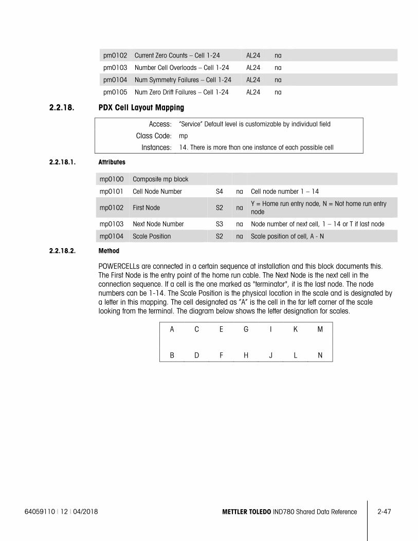
64059110 | 12 | 04/2018 METTLER TOLEDO IND780 Shared Data Reference 2-47
pm0102 Current Zero Counts – Cell 1-24 AL24 na
pm0103 Number Cell Overloads – Cell 1-24 AL24 na
pm0104 Num Symmetry Failures – Cell 1-24 AL24 na
pm0105 Num Zero Drift Failures – Cell 1-24 AL24 na
2.2.18. PDX Cell Layout Mapping
Access: “Service” Default level is customizable by individual field
Class Code: mp
Instances: 14. There is more than one instance of each possible cell
2.2.18.1. Attributes
mp0100 Composite mp block
mp0101 Cell Node Number S4 na Cell node number 1 – 14
mp0102 First Node S2 na Y = Home run entry node, N = Not home run entry node
mp0103 Next Node Number S3 na Node number of next cell, 1 – 14 or T if last node
mp0104 Scale Position S2 na Scale position of cell, A - N
2.2.18.2. Method
POWERCELLs are connected in a certain sequence at installation and this block documents this. The First Node is the entry point of the home run cable. The Next Node is the next cell in the connection sequence. If a cell is the one marked as "terminator", it is the last node. The node numbers can be 1-14. The Scale Position is the physical location in the scale and is designated by a letter in this mapping. The cell designated as “A” is the cell in the far left corner of the scale looking from the terminal. The diagram below shows the letter designation for scales.
A C E G I K M
B D F H J L N
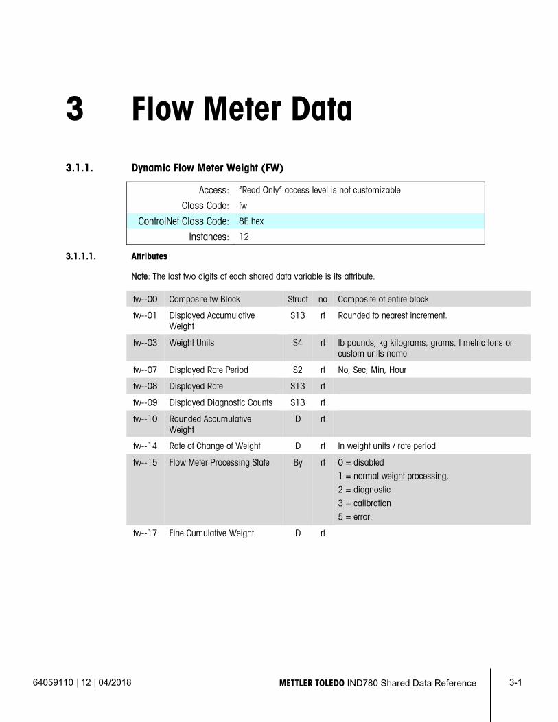
64059110 | 12 | 04/2018 METTLER TOLEDO IND780 Shared Data Reference 3-1
3 Flow Meter Data
3.1.1. Dynamic Flow Meter Weight (FW)
Access: “Read Only” access level is not customizable
Class Code: fw
ControlNet Class Code: 8E hex
Instances: 12
3.1.1.1. Attributes
Note: The last two digits of each shared data variable is its attribute.
fw--00 Composite fw Block Struct na Composite of entire block
fw--01 Displayed Accumulative Weight
S13 rt Rounded to nearest increment.
fw--03 Weight Units S4 rt lb pounds, kg kilograms, grams, t metric tons or custom units name
fw--07 Displayed Rate Period S2 rt No, Sec, Min, Hour
fw--08 Displayed Rate S13 rt
fw--09 Displayed Diagnostic Counts S13 rt
fw--10 Rounded Accumulative Weight
D rt
fw--14 Rate of Change of Weight D rt In weight units / rate period
fw--15 Flow Meter Processing State By rt 0 = disabled
1 = normal weight processing,
2 = diagnostic
3 = calibration
5 = error.
fw--17 Fine Cumulative Weight D rt
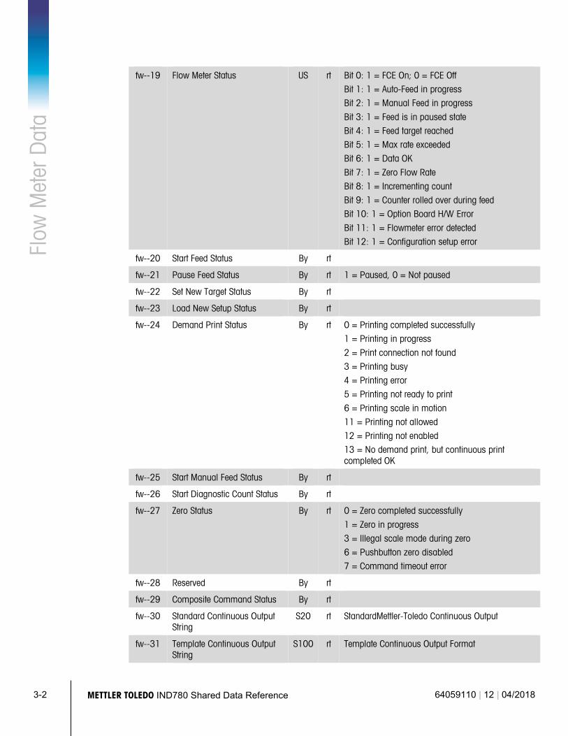
3-2 METTLER TOLEDO IND780 Shared Data Reference 64059110 | 12 | 04/2018
Flow
Met
er D
ata
fw--19 Flow Meter Status US rt Bit 0: 1 = FCE On; 0 = FCE Off
Bit 1: 1 = Auto-Feed in progress
Bit 2: 1 = Manual Feed in progress
Bit 3: 1 = Feed is in paused state
Bit 4: 1 = Feed target reached
Bit 5: 1 = Max rate exceeded
Bit 6: 1 = Data OK
Bit 7: 1 = Zero Flow Rate
Bit 8: 1 = Incrementing count
Bit 9: 1 = Counter rolled over during feed
Bit 10: 1 = Option Board H/W Error
Bit 11: 1 = Flowmeter error detected
Bit 12: 1 = Configuration setup error
fw--20 Start Feed Status By rt
fw--21 Pause Feed Status By rt 1 = Paused, 0 = Not paused
fw--22 Set New Target Status By rt
fw--23 Load New Setup Status By rt
fw--24 Demand Print Status By rt 0 = Printing completed successfully
1 = Printing in progress
2 = Print connection not found
3 = Printing busy
4 = Printing error
5 = Printing not ready to print
6 = Printing scale in motion
11 = Printing not allowed
12 = Printing not enabled
13 = No demand print, but continuous print completed OK
fw--25 Start Manual Feed Status By rt
fw--26 Start Diagnostic Count Status By rt
fw--27 Zero Status By rt 0 = Zero completed successfully
1 = Zero in progress
3 = Illegal scale mode during zero
6 = Pushbutton zero disabled
7 = Command timeout error
fw--28 Reserved By rt
fw--29 Composite Command Status By rt
fw--30 Standard Continuous Output String
S20 rt StandardMettler-Toledo Continuous Output
fw--31 Template Continuous Output String
S100 rt Template Continuous Output Format
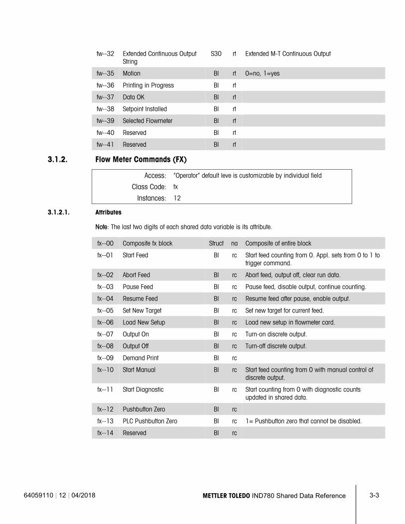
64059110 | 12 | 04/2018 METTLER TOLEDO IND780 Shared Data Reference 3-3
fw--32 Extended Continuous Output String
S30 rt Extended M-T Continuous Output
fw--35 Motion Bl rt 0=no, 1=yes
fw--36 Printing in Progress Bl rt
fw--37 Data OK Bl rt
fw--38 Setpoint Installed Bl rt
fw--39 Selected Flowmeter Bl rt
fw--40 Reserved Bl rt
fw--41 Reserved Bl rt
3.1.2. Flow Meter Commands (FX)
Access: “Operator” default leve is customizable by individual field
Class Code: fx
Instances: 12
3.1.2.1. Attributes
Note: The last two digits of each shared data variable is its attribute.
fx--00 Composite fx block Struct na Composite of entire block
fx--01 Start Feed Bl rc Start feed counting from 0. Appl. sets from 0 to 1 to trigger command.
fx--02 Abort Feed Bl rc Abort feed, output off, clear run data.
fx--03 Pause Feed Bl rc Pause feed, disable output, continue counting.
fx--04 Resume Feed Bl rc Resume feed after pause, enable output.
fx--05 Set New Target Bl rc Set new target for current feed.
fx--06 Load New Setup Bl rc Load new setup in flowmeter card.
fx--07 Output On Bl rc Turn-on discrete output.
fx--08 Output Off Bl rc Turn-off discrete output.
fx--09 Demand Print Bl rc
fx--10 Start Manual Bl rc Start feed counting from 0 with manual control of discrete output.
fx--11 Start Diagnostic Bl rc Start counting from 0 with diagnostic counts updated in shared data.
fx--12 Pushbutton Zero Bl rc
fx--13 PLC Pushbutton Zero Bl rc 1= Pushbutton zero that cannot be disabled.
fx--14 Reserved Bl rc
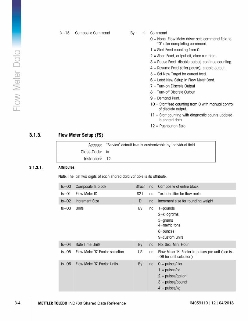
3-4 METTLER TOLEDO IND780 Shared Data Reference 64059110 | 12 | 04/2018
Flow
Met
er D
ata
fx--15 Composite Command By rt Command
0 = None. Flow Meter driver sets command field to “0” after completing command.
1 = Start Feed counting from 0.
2 = Abort Feed, output off, clear run data.
3 = Pause Feed, disable output, continue counting.
4 = Resume Feed (after pause), enable output.
5 = Set New Target for current feed.
6 = Load New Setup in Flow Meter Card.
7 = Turn-on Discrete Output
8 = Turn-off Discrete Output
9 = Demand Print.
10 = Start feed counting from 0 with manual control of discrete output.
11 = Start counting with diagnostic counts updated in shared data.
12 = Pushbutton Zero
3.1.3. Flow Meter Setup (FS)
Access: “Service” default leve is customizable by individual field
Class Code: fx
Instances: 12
3.1.3.1. Attributes
Note: The last two digits of each shared data variable is its attribute.
fs--00 Composite fs block Struct na Composite of entire block
fs--01 Flow Meter ID S21 na Text Identifier for flow meter
fs--02 Increment Size D na Increment size for rounding weight
fs--03 Units By na 1=pounds
2=kilograms
3=grams 4=metric tons
8=ounces
9=custom units
fs--04 Rate Time Units By na No, Sec, Min, Hour
fs--05 Flow Meter ‘K’ Factor selection US na Flow Meter ‘K’ Factor in pulses per unit (see fs--06 for unit selection)
fs--06 Flow Meter ‘K’ Factor Units By na 0 = pulses/liter
1 = pulses/cc
2 = pulses/gallon
3 = pulses/pound
4 = pulses/kg
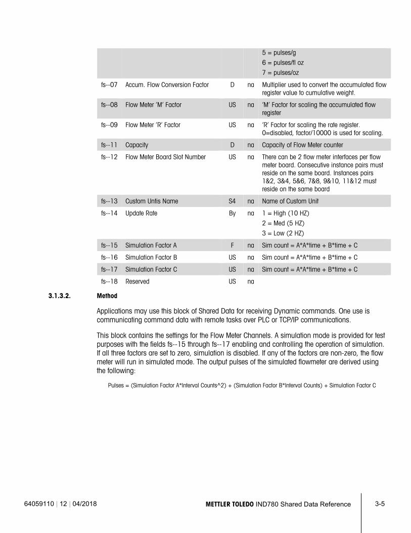
64059110 | 12 | 04/2018 METTLER TOLEDO IND780 Shared Data Reference 3-5
5 = pulses/g
6 = pulses/fl oz
7 = pulses/oz
fs--07 Accum. Flow Conversion Factor D na Multiplier used to convert the accumulated flow register value to cumulative weight.
fs--08 Flow Meter ‘M’ Factor US na ‘M’ Factor for scaling the accumulated flow register
fs--09 Flow Meter ‘R’ Factor US na ‘R’ Factor for scaling the rate register. 0=disabled, factor/10000 is used for scaling.
fs--11 Capacity D na Capacity of Flow Meter counter
fs--12 Flow Meter Board Slot Number US na There can be 2 flow meter interfaces per flow meter board. Consecutive instance pairs must reside on the same board. Instances pairs 1&2, 3&4, 5&6, 7&8, 9&10, 11&12 must reside on the same board
fs--13 Custom Untis Name S4 na Name of Custom Unit
fs--14 Update Rate By na 1 = High (10 HZ)
2 = Med (5 HZ)
3 = Low (2 HZ)
fs--15 Simulation Factor A F na Sim count = A*A*time + B*time + C
fs--16 Simulation Factor B US na Sim count = A*A*time + B*time + C
fs--17 Simulation Factor C US na Sim count = A*A*time + B*time + C
fs--18 Reserved US na
3.1.3.2. Method
Applications may use this block of Shared Data for receiving Dynamic commands. One use is communicating command data with remote tasks over PLC or TCP/IP communications.
This block contains the settings for the Flow Meter Channels. A simulation mode is provided for test purposes with the fields fs--15 through fs--17 enabling and controlling the operation of simulation. If all three factors are set to zero, simulation is disabled. If any of the factors are non-zero, the flow meter will run in simulated mode. The output pulses of the simulated flowmeter are derived using the following:
Pulses = (Simulation Factor A*Interval Counts^2) + (Simulation Factor B*Interval Counts) + Simulation Factor C
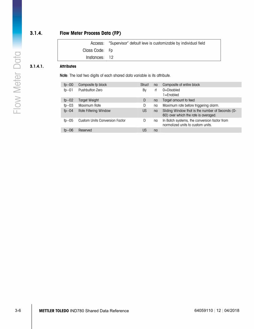
3-6 METTLER TOLEDO IND780 Shared Data Reference 64059110 | 12 | 04/2018
Flow
Met
er D
ata
3.1.4. Flow Meter Process Data (FP)
Access: “Supervisor” default leve is customizable by individual field
Class Code: Fp
Instances: 12
3.1.4.1. Attributes
Note: The last two digits of each shared data variable is its attribute.
fp--00 Composite fp block Struct na Composite of entire block fp--01 Pushbutton Zero By rt 0=Disabled
1=Enabled fp--02 Target Weight D na Target amount to feed fp--03 Maximum Rate D na Maximum rate before triggering alarm. fp--04 Rate Filtering Window US na Sliding Window that is the number of Seconds (0-
60) over which the rate is averaged. fp--05 Custom Units Conversion Factor D na In Batch systems, the conversion factor from
normalized units to custom units. fp--06 Reserved US na
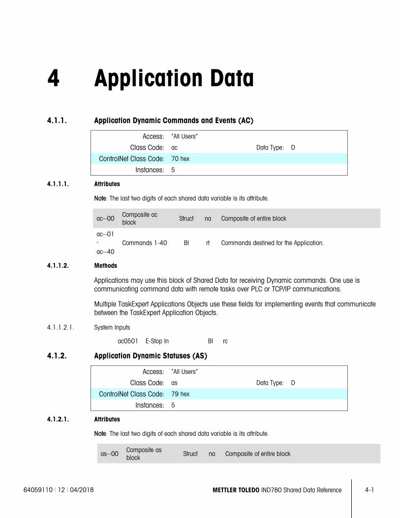
64059110 | 12 | 04/2018 METTLER TOLEDO IND780 Shared Data Reference 4-1
4 Application Data
4.1.1. Application Dynamic Commands and Events (AC)
Access: “All Users”
Class Code: ac Data Type: D
ControlNet Class Code: 70 hex
Instances: 5
4.1.1.1. Attributes
Note: The last two digits of each shared data variable is its attribute.
ac--00 Composite ac block
Struct na Composite of entire block
ac--01 -
ac--40 Commands 1-40 Bl rt Commands destined for the Application.
4.1.1.2. Methods
Applications may use this block of Shared Data for receiving Dynamic commands. One use is communicating command data with remote tasks over PLC or TCP/IP communications.
Multiple TaskExpert Applications Objects use these fields for implementing events that communicate between the TaskExpert Application Objects.
4.1.1.2.1. System Inputs
ac0501 E-Stop In Bl rc
4.1.2. Application Dynamic Statuses (AS)
Access: “All Users”
Class Code: as Data Type: D
ControlNet Class Code: 79 hex
Instances: 5
4.1.2.1. Attributes
Note: The last two digits of each shared data variable is its attribute.
as--00 Composite as block
Struct na Composite of entire block
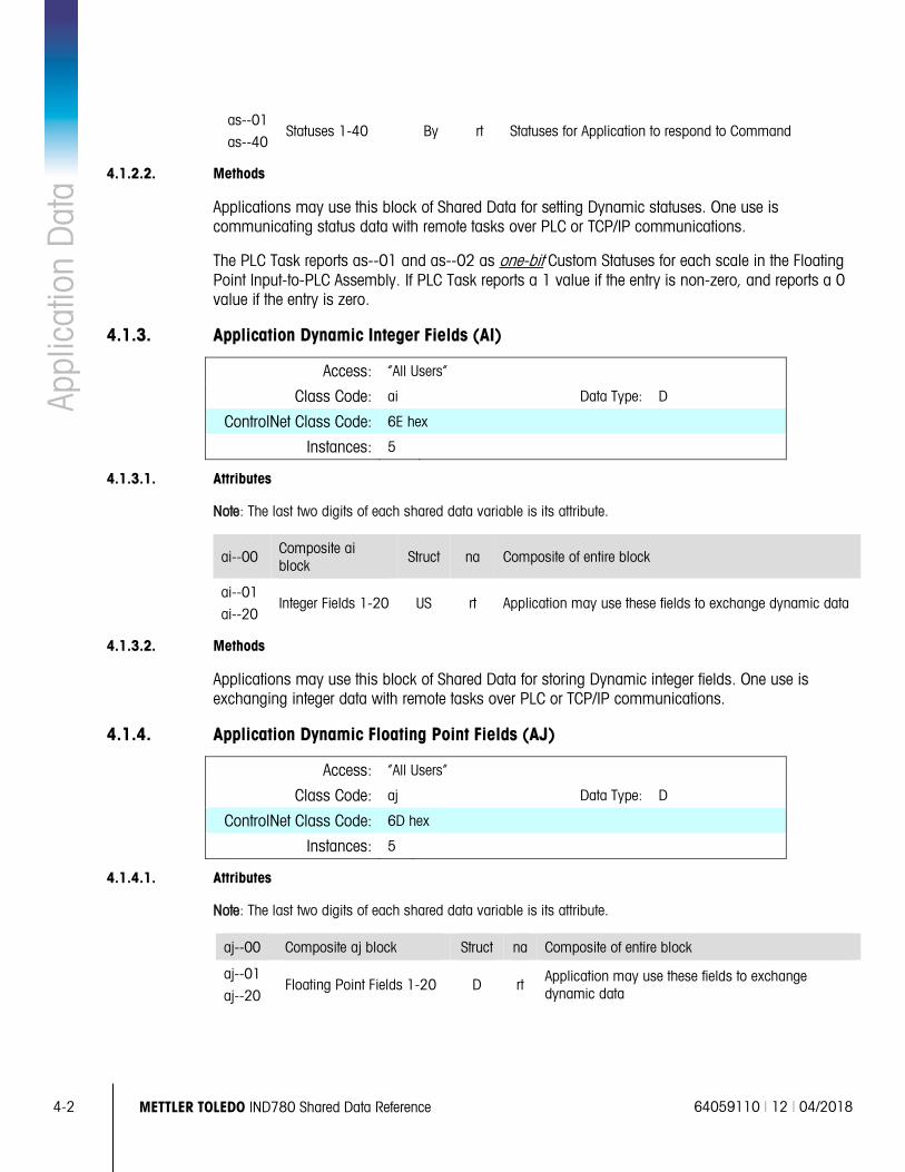
4-2 METTLER TOLEDO IND780 Shared Data Reference 64059110 | 12 | 04/2018
Appl
icat
ion
Dat
a as--01
as--40 Statuses 1-40 By rt Statuses for Application to respond to Command
4.1.2.2. Methods
Applications may use this block of Shared Data for setting Dynamic statuses. One use is communicating status data with remote tasks over PLC or TCP/IP communications.
The PLC Task reports as--01 and as--02 as one-bit Custom Statuses for each scale in the Floating Point Input-to-PLC Assembly. If PLC Task reports a 1 value if the entry is non-zero, and reports a 0 value if the entry is zero.
4.1.3. Application Dynamic Integer Fields (AI)
Access: “All Users”
Class Code: ai Data Type: D
ControlNet Class Code: 6E hex
Instances: 5
4.1.3.1. Attributes
Note: The last two digits of each shared data variable is its attribute.
ai--00 Composite ai block
Struct na Composite of entire block
ai--01
ai--20 Integer Fields 1-20 US rt Application may use these fields to exchange dynamic data
4.1.3.2. Methods
Applications may use this block of Shared Data for storing Dynamic integer fields. One use is exchanging integer data with remote tasks over PLC or TCP/IP communications.
4.1.4. Application Dynamic Floating Point Fields (AJ)
Access: “All Users”
Class Code: aj Data Type: D
ControlNet Class Code: 6D hex
Instances: 5
4.1.4.1. Attributes
Note: The last two digits of each shared data variable is its attribute.
aj--00 Composite aj block Struct na Composite of entire block
aj--01
aj--20 Floating Point Fields 1-20 D rt Application may use these fields to exchange
dynamic data
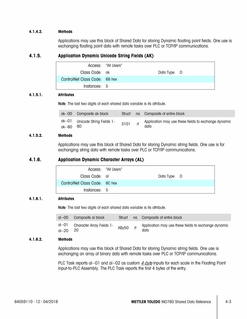
64059110 | 12 | 04/2018 METTLER TOLEDO IND780 Shared Data Reference 4-3
4.1.4.2. Methods
Applications may use this block of Shared Data for storing Dynamic floating point fields. One use is exchanging floating point data with remote tasks over PLC or TCP/IP communications.
4.1.5. Application Dynamic Unicode String Fields (AK)
Access: “All Users”
Class Code: ak Data Type: D
ControlNet Class Code: 6B hex
Instances: 5
4.1.5.1. Attributes
Note: The last two digits of each shared data variable is its attribute.
ak--00 Composite ak block Struct na Composite of entire block
ak--01
ak--60 Unicode String Fields 1-60 S101 rt
Application may use these fields to exchange dynamic data
4.1.5.2. Methods
Applications may use this block of Shared Data for storing Dynamic string fields. One use is for exchanging string data with remote tasks over PLC or TCP/IP communications.
4.1.6. Application Dynamic Character Arrays (AL)
Access: “All Users”
Class Code: al Data Type: D
ControlNet Class Code: 6C hex
Instances: 5
4.1.6.1. Attributes
Note: The last two digits of each shared data variable is its attribute.
al--00 Composite al block Struct na Composite of entire block
al--01
al--20 Character Array Fields 1-20 ABy50 rt
Application may use these fields to exchange dynamic data
4.1.6.2. Methods
Applications may use this block of Shared Data for storing Dynamic string fields. One use is exchanging an array of binary data with remote tasks over PLC or TCP/IP communications.
PLC Task reports al--01 and al--02 as custom 4-byte inputs for each scale in the Floating Point Input-to-PLC Assembly. The PLC Task reports the first 4 bytes of the entry.
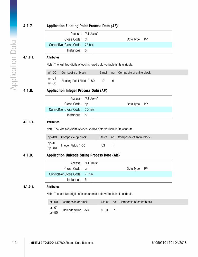
4-4 METTLER TOLEDO IND780 Shared Data Reference 64059110 | 12 | 04/2018
Appl
icat
ion
Dat
a 4.1.7. Application Floating Point Process Data (AF)
Access: “All Users”
Class Code: af Data Type: PP
ControlNet Class Code: 7E hex
Instances: 5
4.1.7.1. Attributes
Note: The last two digits of each shared data variable is its attribute.
af--00 Composite af block Struct na Composite of entire block
af--01
af--80 Floating Point Fields 1-80 D rt
4.1.8. Application Integer Process Data (AP)
Access: “All Users”
Class Code: ap Data Type: PP
ControlNet Class Code: 7D hex
Instances: 5
4.1.8.1. Attributes
Note: The last two digits of each shared data variable is its attribute.
ap--00 Composite ap block Struct na Composite of entire block
ap--01
ap--50 Integer Fields 1-50 US rt
4.1.9. Application Unicode String Process Data (AR)
Access: “All Users”
Class Code: ar Data Type: PP
ControlNet Class Code: 7F hex
Instances: 5
4.1.9.1. Attributes
Note: The last two digits of each shared data variable is its attribute.
ar--00 Composite ar block Struct na Composite of entire block
ar--01
ar--50 Unicode String 1-50 S101 rt
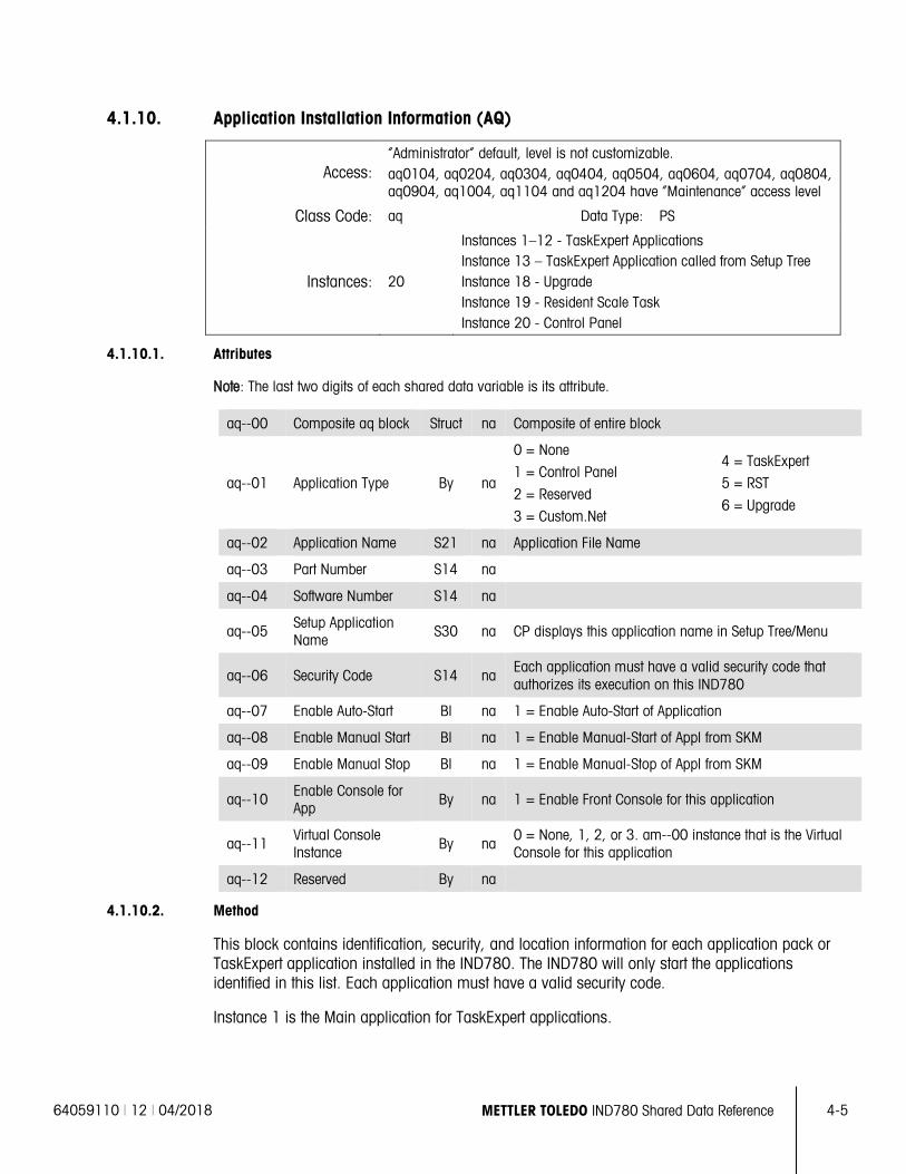
64059110 | 12 | 04/2018 METTLER TOLEDO IND780 Shared Data Reference 4-5
4.1.10. Application Installation Information (AQ)
Access: “Administrator” default, level is not customizable. aq0104, aq0204, aq0304, aq0404, aq0504, aq0604, aq0704, aq0804, aq0904, aq1004, aq1104 and aq1204 have “Maintenance” access level
Class Code: aq Data Type: PS
Instances: 20
Instances 1–12 - TaskExpert Applications Instance 13 – TaskExpert Application called from Setup Tree Instance 18 - Upgrade Instance 19 - Resident Scale Task Instance 20 - Control Panel
4.1.10.1. Attributes
Note: The last two digits of each shared data variable is its attribute.
aq--00 Composite aq block Struct na Composite of entire block
aq--01 Application Type By na
0 = None
1 = Control Panel
2 = Reserved
3 = Custom.Net
4 = TaskExpert
5 = RST
6 = Upgrade
aq--02 Application Name S21 na Application File Name
aq--03 Part Number S14 na
aq--04 Software Number S14 na
aq--05 Setup Application Name
S30 na CP displays this application name in Setup Tree/Menu
aq--06 Security Code S14 na Each application must have a valid security code that authorizes its execution on this IND780
aq--07 Enable Auto-Start Bl na 1 = Enable Auto-Start of Application
aq--08 Enable Manual Start Bl na 1 = Enable Manual-Start of Appl from SKM
aq--09 Enable Manual Stop Bl na 1 = Enable Manual-Stop of Appl from SKM
aq--10 Enable Console for App
By na 1 = Enable Front Console for this application
aq--11 Virtual Console Instance By na
0 = None, 1, 2, or 3. am--00 instance that is the Virtual Console for this application
aq--12 Reserved By na
4.1.10.2. Method
This block contains identification, security, and location information for each application pack or TaskExpert application installed in the IND780. The IND780 will only start the applications identified in this list. Each application must have a valid security code.
Instance 1 is the Main application for TaskExpert applications.
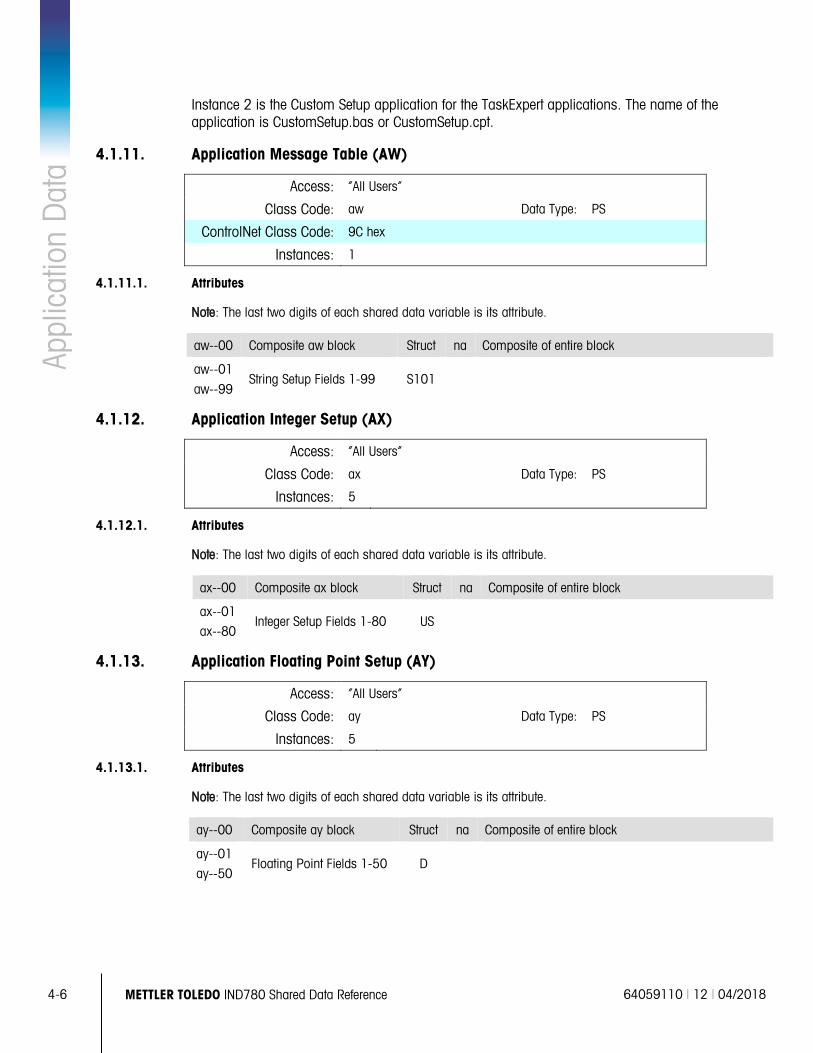
4-6 METTLER TOLEDO IND780 Shared Data Reference 64059110 | 12 | 04/2018
Appl
icat
ion
Dat
a Instance 2 is the Custom Setup application for the TaskExpert applications. The name of the application is CustomSetup.bas or CustomSetup.cpt.
4.1.11. Application Message Table (AW)
Access: “All Users”
Class Code: aw Data Type: PS
ControlNet Class Code: 9C hex
Instances: 1
4.1.11.1. Attributes
Note: The last two digits of each shared data variable is its attribute.
aw--00 Composite aw block Struct na Composite of entire block
aw--01
aw--99 String Setup Fields 1-99 S101
4.1.12. Application Integer Setup (AX)
Access: “All Users”
Class Code: ax Data Type: PS
Instances: 5
4.1.12.1. Attributes
Note: The last two digits of each shared data variable is its attribute.
ax--00 Composite ax block Struct na Composite of entire block
ax--01
ax--80 Integer Setup Fields 1-80 US
4.1.13. Application Floating Point Setup (AY)
Access: “All Users”
Class Code: ay Data Type: PS
Instances: 5
4.1.13.1. Attributes
Note: The last two digits of each shared data variable is its attribute.
ay--00 Composite ay block Struct na Composite of entire block
ay--01
ay--50 Floating Point Fields 1-50 D
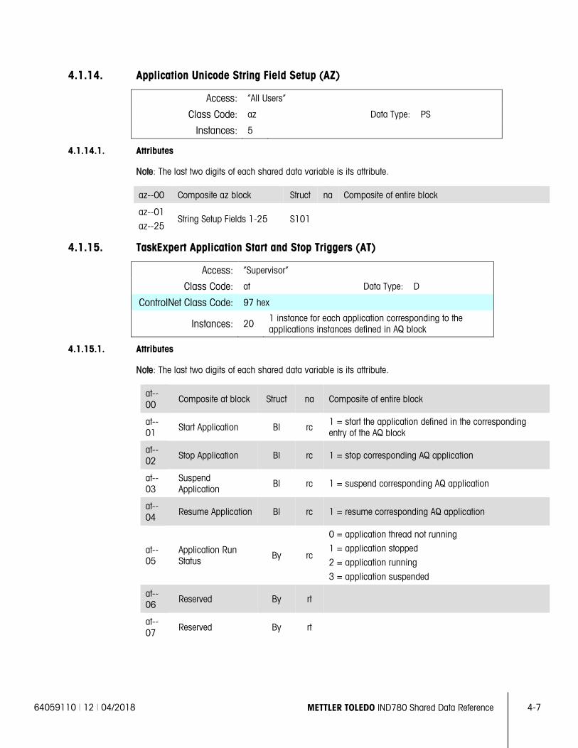
64059110 | 12 | 04/2018 METTLER TOLEDO IND780 Shared Data Reference 4-7
4.1.14. Application Unicode String Field Setup (AZ)
Access: “All Users”
Class Code: az Data Type: PS
Instances: 5
4.1.14.1. Attributes
Note: The last two digits of each shared data variable is its attribute.
az--00 Composite az block Struct na Composite of entire block
az--01
az--25 String Setup Fields 1-25 S101
4.1.15. TaskExpert Application Start and Stop Triggers (AT)
Access: “Supervisor”
Class Code: at Data Type: D
ControlNet Class Code: 97 hex
Instances: 20 1 instance for each application corresponding to the applications instances defined in AQ block
4.1.15.1. Attributes
Note: The last two digits of each shared data variable is its attribute.
at--00
Composite at block Struct na Composite of entire block
at--01
Start Application Bl rc 1 = start the application defined in the corresponding entry of the AQ block
at--02
Stop Application Bl rc 1 = stop corresponding AQ application
at--03
Suspend Application
Bl rc 1 = suspend corresponding AQ application
at--04
Resume Application Bl rc 1 = resume corresponding AQ application
at--05
Application Run Status
By rc
0 = application thread not running
1 = application stopped
2 = application running
3 = application suspended
at--06
Reserved By rt
at--07
Reserved By rt
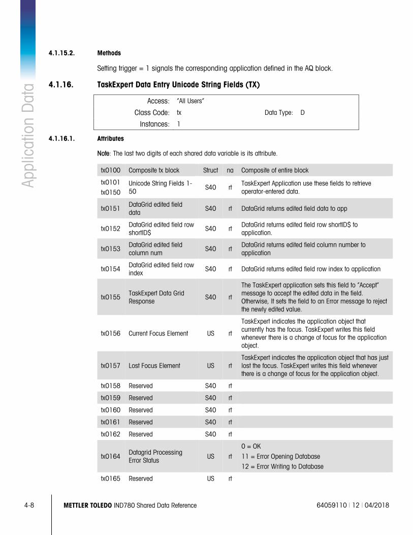
4-8 METTLER TOLEDO IND780 Shared Data Reference 64059110 | 12 | 04/2018
Appl
icat
ion
Dat
a 4.1.15.2. Methods
Setting trigger = 1 signals the corresponding application defined in the AQ block.
4.1.16. TaskExpert Data Entry Unicode String Fields (TX)
Access: “All Users”
Class Code: tx Data Type: D
Instances: 1
4.1.16.1. Attributes
Note: The last two digits of each shared data variable is its attribute.
tx0100 Composite tx block Struct na Composite of entire block
tx0101
tx0150 Unicode String Fields 1-50
S40 rt TaskExpert Application use these fields to retrieve operator-entered data.
tx0151 DataGrid edited field data
S40 rt DataGrid returns edited field data to app
tx0152 DataGrid edited field row shortID$
S40 rt DataGrid returns edited field row shortID$ to application.
tx0153 DataGrid edited field column num
S40 rt DataGrid returns edited field column number to application
tx0154 DataGrid edited field row index
S40 rt DataGrid returns edited field row index to application
tx0155 TaskExpert Data Grid Response
S40 rt
The TaskExpert application sets this field to “Accept” message to accept the edited data in the field. Otherwise, It sets the field to an Error message to reject the newly edited value.
tx0156 Current Focus Element US rt
TaskExpert indicates the application object that currently has the focus. TaskExpert writes this field whenever there is a change of focus for the application object.
tx0157 Lost Focus Element US rt TaskExpert indicates the application object that has just lost the focus. TaskExpert writes this field whenever there is a change of focus for the application object.
tx0158 Reserved S40 rt
tx0159 Reserved S40 rt
tx0160 Reserved S40 rt
tx0161 Reserved S40 rt
tx0162 Reserved S40 rt
tx0164 Datagrid Processing Error Status US rt
0 = OK
11 = Error Opening Database
12 = Error Writing to Database
tx0165 Reserved US rt
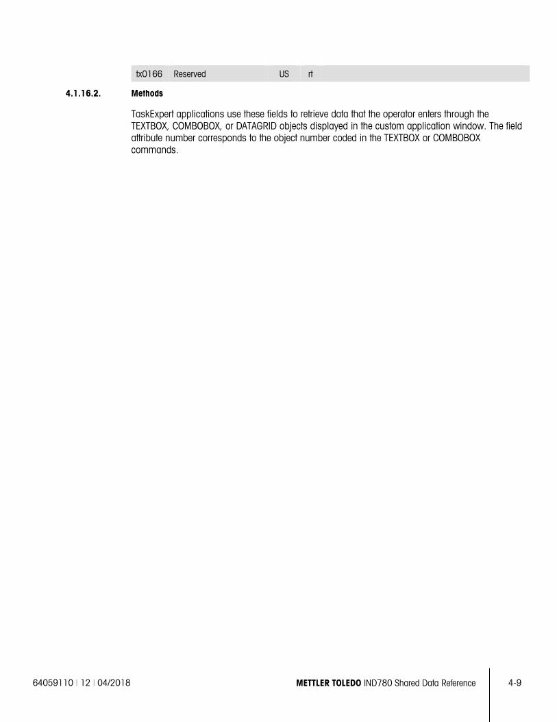
64059110 | 12 | 04/2018 METTLER TOLEDO IND780 Shared Data Reference 4-9
tx0166 Reserved US rt
4.1.16.2. Methods
TaskExpert applications use these fields to retrieve data that the operator enters through the TEXTBOX, COMBOBOX, or DATAGRID objects displayed in the custom application window. The field attribute number corresponds to the object number coded in the TEXTBOX or COMBOBOX commands.
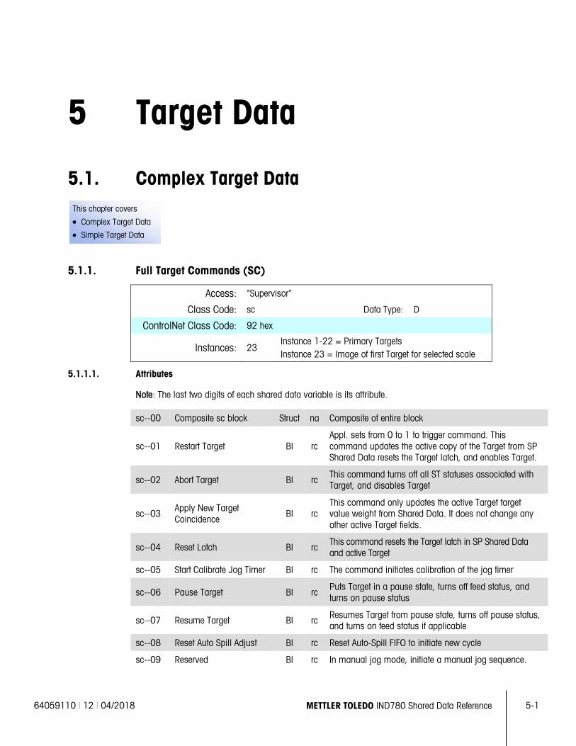
64059110 | 12 | 04/2018 METTLER TOLEDO IND780 Shared Data Reference 5-1
This chapter covers
• Complex Target Data
• Simple Target Data
5 Target Data
5.1. Complex Target Data
5.1.1. Full Target Commands (SC)
Access: “Supervisor”
Class Code: sc Data Type: D
ControlNet Class Code: 92 hex
Instances: 23 Instance 1-22 = Primary Targets Instance 23 = Image of first Target for selected scale
5.1.1.1. Attributes
Note: The last two digits of each shared data variable is its attribute.
sc--00 Composite sc block Struct na Composite of entire block
sc--01 Restart Target Bl rc Appl. sets from 0 to 1 to trigger command. This command updates the active copy of the Target from SP Shared Data resets the Target latch, and enables Target.
sc--02 Abort Target Bl rc This command turns off all ST statuses associated with Target, and disables Target
sc--03 Apply New Target Coincidence
Bl rc This command only updates the active Target target value weight from Shared Data. It does not change any other active Target fields.
sc--04 Reset Latch Bl rc This command resets the Target latch in SP Shared Data and active Target
sc--05 Start Calibrate Jog Timer Bl rc The command initiates calibration of the jog timer
sc--06 Pause Target Bl rc Puts Target in a pause state, turns off feed status, and turns on pause status
sc--07 Resume Target Bl rc Resumes Target from pause state, turns off pause status, and turns on feed status if applicable
sc--08 Reset Auto Spill Adjust Bl rc Reset Auto-Spill FIFO to initiate new cycle
sc--09 Reserved Bl rc In manual jog mode, initiate a manual jog sequence.
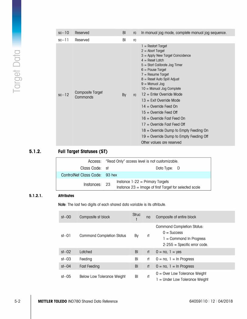
5-2 METTLER TOLEDO IND780 Shared Data Reference 64059110 | 12 | 04/2018
Targ
et D
ata
sc--10 Reserved Bl rc In manual jog mode, complete manual jog sequence.
sc--11 Reserved Bl rc
sc--12 Composite Target Commands By rc
1 = Restart Target 2 = Abort Target 3 = Apply New Target Coincidence 4 = Reset Latch 5 = Start Calibrate Jog Timer 6 = Pause Target 7 = Resume Target 8 = Reset Auto Spill Adjust 9 = Manual Jog 10 = Manual Jog Complete
12 = Enter Override Mode
13 = Exit Override Mode
14 = Override Feed On
15 = Override Feed Off
16 = Override Fast Feed On
17 = Override Fast Feed Off
18 = Override Dump to Empty Feeding On
19 = Override Dump to Empty Feeding Off
Other values are reserved
5.1.2. Full Target Statuses (ST)
Access: “Read Only” access level is not customizable.
Class Code: st Data Type: D
ControlNet Class Code: 93 hex
Instances: 23 Instance 1-22 = Primary Targets Instance 23 = Image of first Target for selected scale
5.1.2.1. Attributes
Note: The last two digits of each shared data variable is its attribute.
st--00 Composite st block Struct
na Composite of entire block
st--01 Command Completion Status By rt
Command Completion Status:
0 = Success
1 = Command In Progress
2-255 = Specific error code.
st--02 Latched Bl rt 0 = no, 1 = yes
st--03 Feeding Bl rt 0 = no, 1 = In Progress
st--04 Fast Feeding Bl rt 0 = no, 1 = In Progress
st--05 Below Low Tolerance Weight Bl rt 0 = Over Low Tolerance Weight
1 = Under Low Tolerance Weight
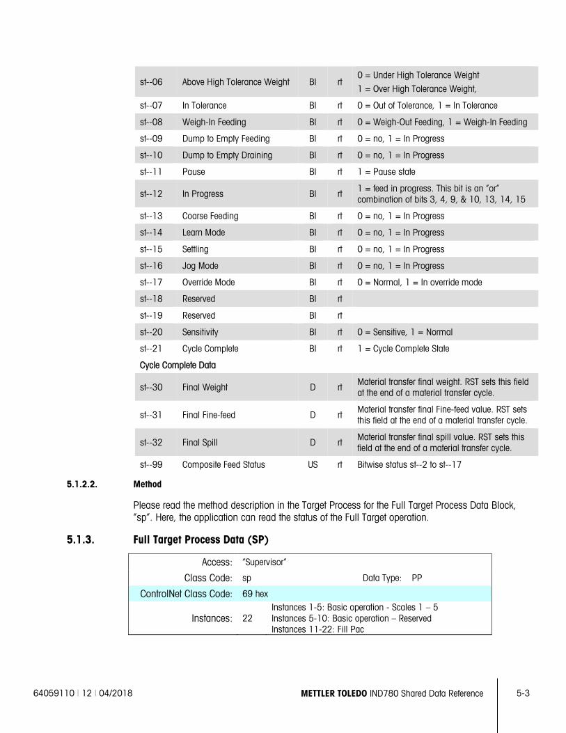
64059110 | 12 | 04/2018 METTLER TOLEDO IND780 Shared Data Reference 5-3
st--06 Above High Tolerance Weight Bl rt 0 = Under High Tolerance Weight
1 = Over High Tolerance Weight,
st--07 In Tolerance Bl rt 0 = Out of Tolerance, 1 = In Tolerance
st--08 Weigh-In Feeding Bl rt 0 = Weigh-Out Feeding, 1 = Weigh-In Feeding
st--09 Dump to Empty Feeding Bl rt 0 = no, 1 = In Progress
st--10 Dump to Empty Draining Bl rt 0 = no, 1 = In Progress
st--11 Pause Bl rt 1 = Pause state
st--12 In Progress Bl rt 1 = feed in progress. This bit is an “or” combination of bits 3, 4, 9, & 10, 13, 14, 15
st--13 Coarse Feeding BI rt 0 = no, 1 = In Progress
st--14 Learn Mode BI rt 0 = no, 1 = In Progress
st--15 Settling BI rt 0 = no, 1 = In Progress
st--16 Jog Mode BI rt 0 = no, 1 = In Progress
st--17 Override Mode Bl rt 0 = Normal, 1 = In override mode
st--18 Reserved BI rt
st--19 Reserved BI rt
st--20 Sensitivity BI rt 0 = Sensitive, 1 = Normal
st--21 Cycle Complete BI rt 1 = Cycle Complete State
Cycle Complete Data
st--30 Final Weight D rt Material transfer final weight. RST sets this field at the end of a material transfer cycle.
st--31 Final Fine-feed D rt Material transfer final Fine-feed value. RST sets this field at the end of a material transfer cycle.
st--32 Final Spill D rt Material transfer final spill value. RST sets this field at the end of a material transfer cycle.
st--99 Composite Feed Status US rt Bitwise status st--2 to st--17
5.1.2.2. Method
Please read the method description in the Target Process for the Full Target Process Data Block, ”sp”. Here, the application can read the status of the Full Target operation.
5.1.3. Full Target Process Data (SP)
Access: “Supervisor”
Class Code: sp Data Type: PP
ControlNet Class Code: 69 hex
Instances: 22 Instances 1-5: Basic operation - Scales 1 – 5 Instances 5-10: Basic operation – Reserved Instances 11-22: Fill Pac
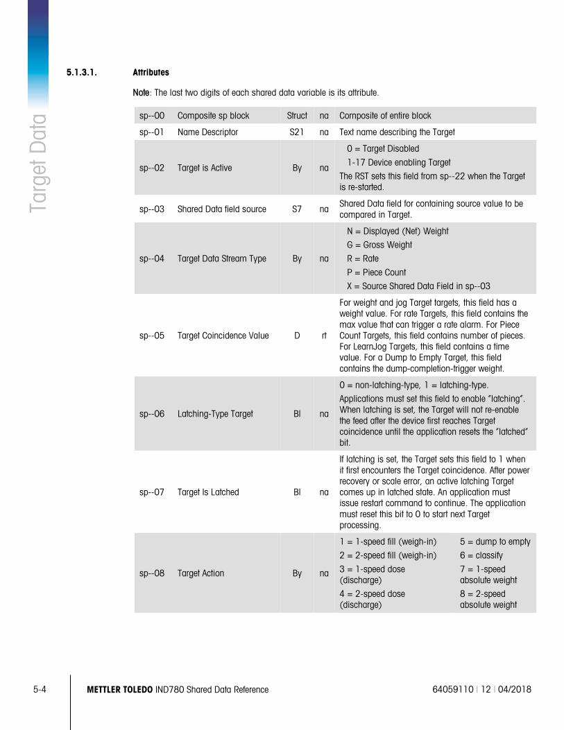
5-4 METTLER TOLEDO IND780 Shared Data Reference 64059110 | 12 | 04/2018
Targ
et D
ata
5.1.3.1. Attributes
Note: The last two digits of each shared data variable is its attribute.
sp--00 Composite sp block Struct na Composite of entire block
sp--01 Name Descriptor S21 na Text name describing the Target
sp--02 Target is Active By na
0 = Target Disabled
1-17 Device enabling Target
The RST sets this field from sp--22 when the Target is re-started.
sp--03 Shared Data field source S7 na Shared Data field for containing source value to be compared in Target.
sp--04 Target Data Stream Type By na
N = Displayed (Net) Weight
G = Gross Weight
R = Rate
P = Piece Count
X = Source Shared Data Field in sp--03
sp--05 Target Coincidence Value D rt
For weight and jog Target targets, this field has a weight value. For rate Targets, this field contains the max value that can trigger a rate alarm. For Piece Count Targets, this field contains number of pieces. For LearnJog Targets, this field contains a time value. For a Dump to Empty Target, this field contains the dump-completion-trigger weight.
sp--06 Latching-Type Target Bl na
0 = non-latching-type, 1 = latching-type.
Applications must set this field to enable “latching”. When latching is set, the Target will not re-enable the feed after the device first reaches Target coincidence until the application resets the “latched” bit.
sp--07 Target Is Latched Bl na
If latching is set, the Target sets this field to 1 when it first encounters the Target coincidence. After power recovery or scale error, an active latching Target comes up in latched state. An application must issue restart command to continue. The application must reset this bit to 0 to start next Target processing.
sp--08 Target Action By na
1 = 1-speed fill (weigh-in)
2 = 2-speed fill (weigh-in)
3 = 1-speed dose (discharge)
4 = 2-speed dose (discharge)
5 = dump to empty
6 = classify
7 = 1-speed absolute weight
8 = 2-speed absolute weight
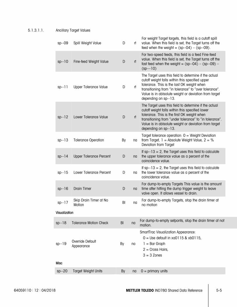
64059110 | 12 | 04/2018 METTLER TOLEDO IND780 Shared Data Reference 5-5
5.1.3.1.1. Ancillary Target Values
sp--09 Spill Weight Value D rt For weight Target targets, this field is a cutoff spill value. When this field is set, the Target turns off the feed when the weight = (sp--04) – (sp--09).
sp--10 Fine-feed Weight Value D rt
For two-speed feeds, this field is a feed Fine-feed value. When this field is set, the Target turns off the fast feed when the weight = (sp--04) – (sp--09) – (sp—10)
sp--11 Upper Tolerance Value D rt
The Target uses this field to determine if the actual cutoff weight falls within this specified upper tolerance. This is the last OK weight when transitioning from “in tolerance” to “over tolerance”. Value is in ablsolute weight or deviation from target depending on sp--13.
sp--12 Lower Tolerance Value D rt
The Target uses this field to determine if the actual cutoff weight falls within this specified lower tolerance. This is the first OK weight when transitioning from “under tolerance” to “in tolerance”. Value is in ablsolute weight or deviation from target depending on sp--13.
sp--13 Tolerance Operation By na Target tolerance operation: 0 = Weight Deviation from Target, 1 = Absolute Weight Value, 2 = % Deviation from Target
sp--14 Upper Tolerance Percent D na If sp--13 = 2, the Target uses this field to calculate the upper tolerance value as a percent of the coincidence value.
sp--15 Lower Tolerance Percent D na If sp--13 = 2, the Target uses this field to calculate the lower tolerance value as a percent of the coincidence value.
sp--16 Drain Timer D na For dump-to-empty Targets This value is the amount time after hitting the dump trigger weight to leave valve open. It allows vessel to drain.
sp--17 Skip Drain Timer at No Motion Bl na
For dump-to-empty Targets, stop the drain timer at no motion
Visualization
sp--18 Tolerance Motion Check Bl na For dump-to-empty setponts, stop the drain timer at not motion.
sp--19 Override Default Appearance By na
SmartTrac Visualization Appearance:
0 = Use default in xa0115 & xb0115,
1 = Bar Graph
2 = Cross Hairs,
3 = 3 Zones
Misc
sp--20 Target Weight Units By na 0 = primary units
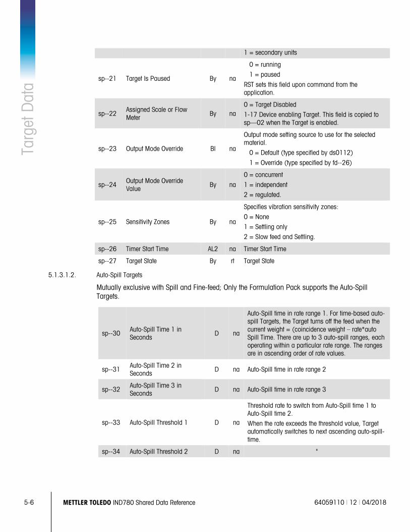
5-6 METTLER TOLEDO IND780 Shared Data Reference 64059110 | 12 | 04/2018
Targ
et D
ata
1 = secondary units
sp--21 Target Is Paused By na
0 = running
1 = paused
RST sets this field upon command from the application.
sp--22 Assigned Scale or Flow Meter
By na 0 = Target Disabled
1-17 Device enabling Target. This field is copied to sp—02 when the Target is enabled.
sp--23 Output Mode Override Bl na
Output mode setting source to use for the selected material.
0 = Default (type specified by ds0112)
1 = Override (type specified by fd--26)
sp--24 Output Mode Override Value
By na
0 = concurrent
1 = independent
2 = regulated.
sp--25 Sensitivity Zones By na
Specifies vibration sensitivity zones:
0 = None
1 = Settling only
2 = Slow feed and Settling.
sp--26 Timer Start Time AL2 na Timer Start Time
sp--27 Target State By rt Target State
5.1.3.1.2. Auto-Spill Targets
Mutually exclusive with Spill and Fine-feed; Only the Formulation Pack supports the Auto-Spill Targets.
sp--30 Auto-Spill Time 1 in Seconds
D na
Auto-Spill time in rate range 1. For time-based auto-spill Targets, the Target turns off the feed when the current weight = (coincidence weight – rate*auto Spill Time. There are up to 3 auto-spill ranges, each operating within a particular rate range. The ranges are in ascending order of rate values.
sp--31 Auto-Spill Time 2 in Seconds
D na Auto-Spill time in rate range 2
sp--32 Auto-Spill Time 3 in Seconds D na Auto-Spill time in rate range 3
sp--33 Auto-Spill Threshold 1 D na
Threshold rate to switch from Auto-Spill time 1 to Auto-Spill time 2.
When the rate exceeds the threshold value, Target automatically switches to next ascending auto-spill-time.
sp--34 Auto-Spill Threshold 2 D na "
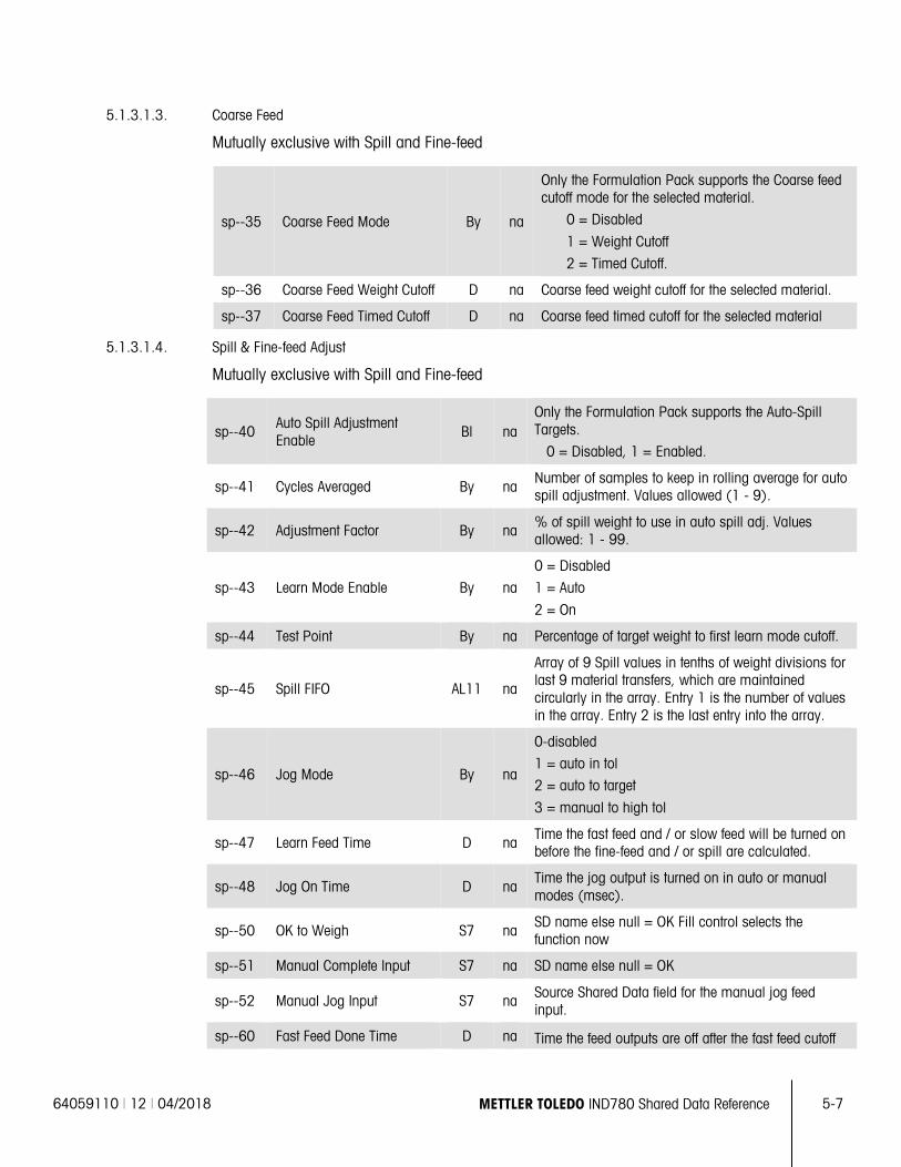
64059110 | 12 | 04/2018 METTLER TOLEDO IND780 Shared Data Reference 5-7
5.1.3.1.3. Coarse Feed
Mutually exclusive with Spill and Fine-feed
sp--35 Coarse Feed Mode By na
Only the Formulation Pack supports the Coarse feed cutoff mode for the selected material.
0 = Disabled
1 = Weight Cutoff
2 = Timed Cutoff.
sp--36 Coarse Feed Weight Cutoff D na Coarse feed weight cutoff for the selected material.
sp--37 Coarse Feed Timed Cutoff D na Coarse feed timed cutoff for the selected material
5.1.3.1.4. Spill & Fine-feed Adjust
Mutually exclusive with Spill and Fine-feed
sp--40 Auto Spill Adjustment Enable
Bl na Only the Formulation Pack supports the Auto-Spill Targets.
0 = Disabled, 1 = Enabled.
sp--41 Cycles Averaged By na Number of samples to keep in rolling average for auto spill adjustment. Values allowed (1 - 9).
sp--42 Adjustment Factor By na % of spill weight to use in auto spill adj. Values allowed: 1 - 99.
sp--43 Learn Mode Enable By na
0 = Disabled
1 = Auto
2 = On
sp--44 Test Point By na Percentage of target weight to first learn mode cutoff.
sp--45 Spill FIFO AL11 na
Array of 9 Spill values in tenths of weight divisions for last 9 material transfers, which are maintained circularly in the array. Entry 1 is the number of values in the array. Entry 2 is the last entry into the array.
sp--46 Jog Mode By na
0-disabled
1 = auto in tol
2 = auto to target
3 = manual to high tol
sp--47 Learn Feed Time D na Time the fast feed and / or slow feed will be turned on before the fine-feed and / or spill are calculated.
sp--48 Jog On Time D na Time the jog output is turned on in auto or manual modes (msec).
sp--50 OK to Weigh S7 na SD name else null = OK Fill control selects the function now
sp--51 Manual Complete Input S7 na SD name else null = OK
sp--52 Manual Jog Input S7 na Source Shared Data field for the manual jog feed input.
sp--60 Fast Feed Done Time D na Time the feed outputs are off after the fast feed cutoff
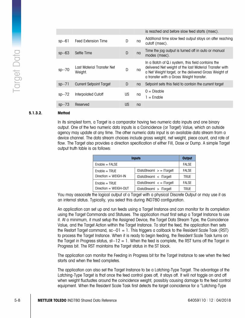
5-8 METTLER TOLEDO IND780 Shared Data Reference 64059110 | 12 | 04/2018
Targ
et D
ata
is reached and before slow feed starts (msec).
sp--61 Feed Extension Time D na Additional time slow feed output stays on after reaching cutoff (msec).
sp--63 Settle Time D na Time the jog output is turned off in auto or manual modes (msec).
sp--70 Last Material Transfer Net Weight.
D na
In a Batch of Q.i system, this field contains the delivered Net weight of the last Material Transfer with a Net Weight target, or the delivered Gross Weight of a transfer with a Gross Weight transfer.
sp--71 Current Setpoint Target D na Setpoint sets this field to contain the current target
sp--72 Interpolated Cutoff US na 0 = Disable
1 = Enable
sp--73 Reserved US na
5.1.3.2. Method
In its simplest form, a Target is a comparator having two numeric data inputs and one binary output. One of the two numeric data inputs is a Coincidence (or Target) Value, which an outside agency may update at any time. The other numeric data input is an available data stream from a device channel. The data stream choices include gross weight, net weight, piece count, and rate of flow. The Target also provides a direction specification of either Fill, Dose or Dump. A simple Target output truth table is as follows:
Inputs Output
Enable = FALSE FALSE
Enable = TRUE Direction = WEIGH-IN
|DataStream| > = |Target| FALSE
|DataStream| < |Target| TRUE
Enable = TRUE Direction = WEIGH-OUT
|DataStream| < = |Target| FALSE
|DataStream| > |Target| TRUE
You may associate the logical output of a Target with a physical Discrete Output or may use it as an internal status. Typically, you select this during IND780 configuration.
An application can set up and run feeds using a Target Instance and can monitor for its completion using the Target Commands and Statuses. The application must first setup a Target Instance to use it. At a minimum, it must setup the Assigned Device, the Target Data Stream Type, the Coincidence Value, and the Target Action within the Target Instance. To start the feed, the application then sets the Restart Target command, sc--01 = 1. This triggers a callback to the Resident Scale Task (RST) to process the Target Instance. When it is ready to begin feeding, the Resident Scale Task turns on the Target in Progress status, st--12 = 1. When the feed is complete, the RST turns off the Target in Progress bit. The RST maintains the Target status in the ST block.
The application can monitor the Feeding in Progress bit for the Target Instance to see when the feed starts and when the feed completes.
The application can also set the Target Instance to be a Latching-Type Target. The advantage of the Latching-Type Target is that once the feed control goes off, it stays off. It will not toggle on and off when weight fluctuates around the coincidence weight, possibly causing damage to the feed control equipment. When the Resident Scale Task first detects the target coincidence for a “Latching-Type
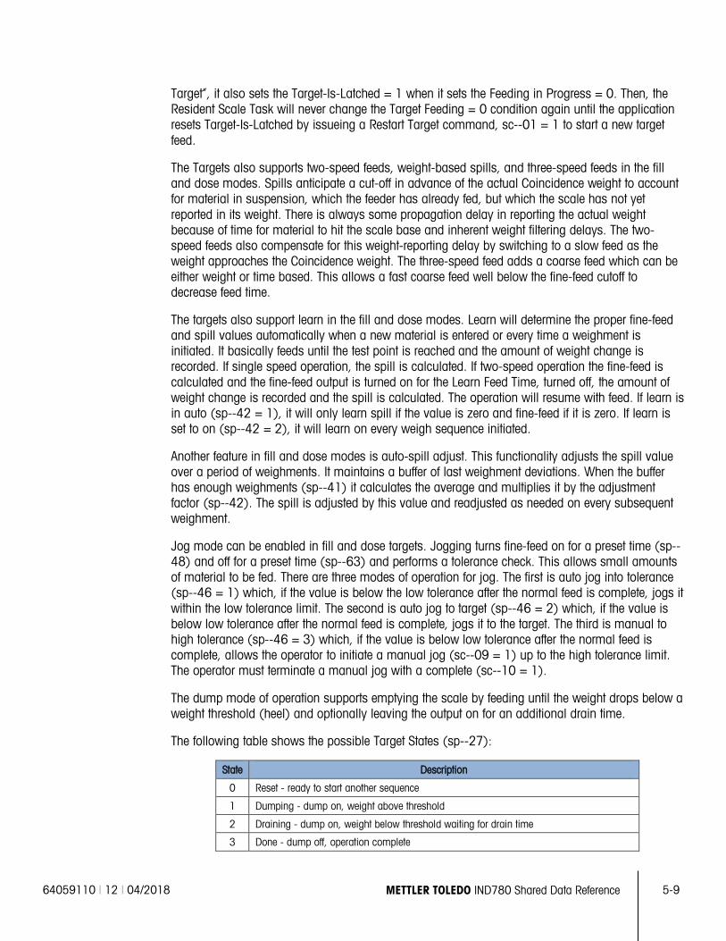
64059110 | 12 | 04/2018 METTLER TOLEDO IND780 Shared Data Reference 5-9
Target”, it also sets the Target-Is-Latched = 1 when it sets the Feeding in Progress = 0. Then, the Resident Scale Task will never change the Target Feeding = 0 condition again until the application resets Target-Is-Latched by issueing a Restart Target command, sc--01 = 1 to start a new target feed.
The Targets also supports two-speed feeds, weight-based spills, and three-speed feeds in the fill and dose modes. Spills anticipate a cut-off in advance of the actual Coincidence weight to account for material in suspension, which the feeder has already fed, but which the scale has not yet reported in its weight. There is always some propagation delay in reporting the actual weight because of time for material to hit the scale base and inherent weight filtering delays. The two-speed feeds also compensate for this weight-reporting delay by switching to a slow feed as the weight approaches the Coincidence weight. The three-speed feed adds a coarse feed which can be either weight or time based. This allows a fast coarse feed well below the fine-feed cutoff to decrease feed time.
The targets also support learn in the fill and dose modes. Learn will determine the proper fine-feed and spill values automatically when a new material is entered or every time a weighment is initiated. It basically feeds until the test point is reached and the amount of weight change is recorded. If single speed operation, the spill is calculated. If two-speed operation the fine-feed is calculated and the fine-feed output is turned on for the Learn Feed Time, turned off, the amount of weight change is recorded and the spill is calculated. The operation will resume with feed. If learn is in auto (sp--42 = 1), it will only learn spill if the value is zero and fine-feed if it is zero. If learn is set to on (sp--42 = 2), it will learn on every weigh sequence initiated.
Another feature in fill and dose modes is auto-spill adjust. This functionality adjusts the spill value over a period of weighments. It maintains a buffer of last weighment deviations. When the buffer has enough weighments (sp--41) it calculates the average and multiplies it by the adjustment factor (sp--42). The spill is adjusted by this value and readjusted as needed on every subsequent weighment.
Jog mode can be enabled in fill and dose targets. Jogging turns fine-feed on for a preset time (sp--48) and off for a preset time (sp--63) and performs a tolerance check. This allows small amounts of material to be fed. There are three modes of operation for jog. The first is auto jog into tolerance (sp--46 = 1) which, if the value is below the low tolerance after the normal feed is complete, jogs it within the low tolerance limit. The second is auto jog to target (sp--46 = 2) which, if the value is below low tolerance after the normal feed is complete, jogs it to the target. The third is manual to high tolerance (sp--46 = 3) which, if the value is below low tolerance after the normal feed is complete, allows the operator to initiate a manual jog (sc--09 = 1) up to the high tolerance limit. The operator must terminate a manual jog with a complete (sc--10 = 1).
The dump mode of operation supports emptying the scale by feeding until the weight drops below a weight threshold (heel) and optionally leaving the output on for an additional drain time.
The following table shows the possible Target States (sp--27):
State Description
0 Reset - ready to start another sequence
1 Dumping - dump on, weight above threshold
2 Draining - dump on, weight below threshold waiting for drain time
3 Done - dump off, operation complete
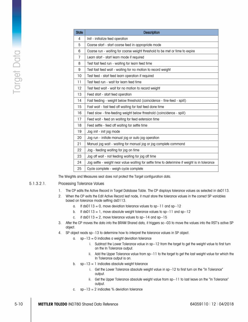
5-10 METTLER TOLEDO IND780 Shared Data Reference 64059110 | 12 | 04/2018
Targ
et D
ata
State Description
4 Init - initialize feed operation
5 Coarse start - start coarse feed in appropriate mode
6 Coarse run - waiting for coarse weight threshold to be met or time to expire
7 Learn start - start learn mode if required
8 Test fast feed run - waiting for learn feed time
9 Test fast feed wait - waiting for no motion to record weight
10 Test feed - start feed learn operation if required
11 Test feed run - wait for learn feed time
12 Test feed wait - wait for no motion to record weight
13 Feed start - start feed operation
14 Fast feeding - weight below threshold (coincidence - fine-feed - spill)
15 Fast wait - fast feed off waiting for fast feed done time
16 Feed slow - fine-feeding weight below threshold (coincidence - spill)
17 Feed wait - feed on waiting for feed extension time
18 Feed settle - feed off waiting tor settle time
19 Jog init - init jog mode
20 Jog run - initiate manual jog or auto jog operation
21 Manual jog wait - waiting for manual jog or jog complete command
22 Jog - feeding waiting for jog on time
23 Jog off wait - not feeding waiting for jog off time
24 Jog settle - weight near value waiting for settle time to deterimine if weight is in tolerance
25 Cycle complete - weigh cycle complete
The Weights and Measures seal does not protect the Target configuration data.
5.1.3.2.1. Processing Tolerance Values
1. The CP edits the Active Record in Target Database Table. The CP displays tolerance values as selected in ds0113.
2. When the CP exits the Edit Active Record leaf node, it must store the tolerance values in the correct SP variables based on tolerance mode setting ds0113.
a. If ds0113 = 0, move deviation tolerance values to sp--11 and sp--12
b. If ds0113 = 1, move absolute weight tolerance values to sp--11 and sp--12
c. if ds0113 = 2, move tolerance values to sp--14 and sp--15
3. After the CP moves the data into the BRAM Shared data, it triggers sc--03 to move the values into the RST’s active SP object.
4. SP object reads sp--13 to determine how to interpret the tolerance values in SP object.
a. sp--13 = 0 indicates a weight deviation tolerance
i. Subtract the Lower Tolerance value in sp--12 from the target to get the weight value to first turn on the In Tolerance output.
ii. Add the Upper Tolerance value from sp--11 to the target to get the last weight value for which the In Tolerance output is on.
b. sp--13 = 1 indicates absolute weight tolerance
i. Get the Lower Tolerance absolute weight value in sp--12 to first turn on the “In Tolerance” output.
ii. Get the Upper Tolerance absolute weight value from sp--11 to last leave on the “In Tolerance” output.
c. sp--13 = 2 indicates % deviation tolerance
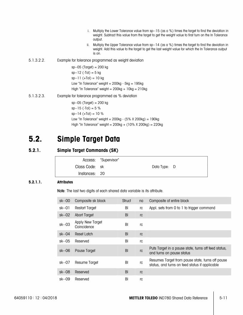
64059110 | 12 | 04/2018 METTLER TOLEDO IND780 Shared Data Reference 5-11
i. Multiply the Lower Tolerance value from sp--15 (as a %) times the target to find the deviation in weight. Subtract this value from the target to get the weight value to first turn on the In Tolerance output.
ii. Multiply the Upper Tolerance value from sp--14 (as a %) times the target to find the deviation in weight. Add this value to the target to get the last weight value for which the In Tolerance output is on.
5.1.3.2.2. Example for tolerance programmed as weight deviation
sp--05 (Target) = 200 kg
sp--12 (-Tol) = 5 kg
sp--11 (+Tol) = 10 kg
Low “In Tolerance” weight = 200kg - 5kg = 195kg
High “In Tolerance” weight = 200kg + 10kg = 210kg
5.1.3.2.3. Example for tolerance programmed as % deviation
sp--05 (Target) = 200 kg
sp--15 (-Tol) = 5 %
sp--14 (+Tol) = 10 %
Low “In Tolerance” weight = 200kg - (5% X 200kg) = 190kg
High “In Tolerance” weight = 200kg + (10% X 200kg) = 220kg
5.2. Simple Target Data 5.2.1. Simple Target Commands (SK)
Access: “Supervisor”
Class Code: sk Data Type: D
Instances: 20
5.2.1.1. Attributes
Note: The last two digits of each shared data variable is its attribute.
sk--00 Composite sk block Struct na Composite of entire block
sk--01 Restart Target Bl rc Appl. sets from 0 to 1 to trigger command
sk--02 Abort Target Bl rc
sk--03 Apply New Target Coincidence Bl rc
sk--04 Reset Latch Bl rc
sk--05 Reserved Bl rc
sk--06 Pause Target Bl rc Puts Target in a pause state, turns off feed status, and turns on pause status
sk--07 Resume Target Bl rc Resumes Target from pause state, turns off pause status, and turns on feed status if applicable
sk--08 Reserved Bl rc
sk--09 Reserved Bl rc
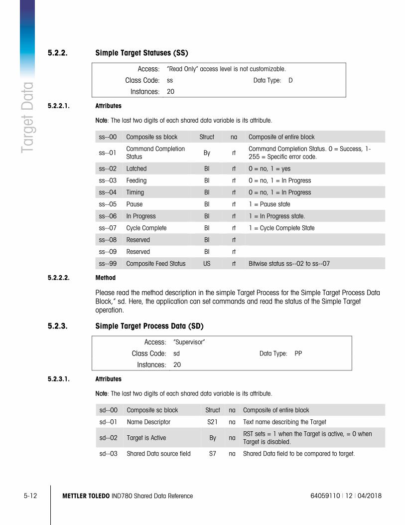
5-12 METTLER TOLEDO IND780 Shared Data Reference 64059110 | 12 | 04/2018
Targ
et D
ata
5.2.2. Simple Target Statuses (SS)
Access: “Read Only” access level is not customizable.
Class Code: ss Data Type: D
Instances: 20
5.2.2.1. Attributes
Note: The last two digits of each shared data variable is its attribute.
ss--00 Composite ss block Struct na Composite of entire block
ss--01 Command Completion Status By rt
Command Completion Status. 0 = Success, 1-255 = Specific error code.
ss--02 Latched Bl rt 0 = no, 1 = yes
ss--03 Feeding Bl rt 0 = no, 1 = In Progress
ss--04 Timing Bl rt 0 = no, 1 = In Progress
ss--05 Pause Bl rt 1 = Pause state
ss--06 In Progress Bl rt 1 = In Progress state.
ss--07 Cycle Complete BI rt 1 = Cycle Complete State
ss--08 Reserved BI rt
ss--09 Reserved BI rt
ss--99 Composite Feed Status US rt Bitwise status ss--02 to ss--07
5.2.2.2. Method
Please read the method description in the simple Target Process for the Simple Target Process Data Block,” sd. Here, the application can set commands and read the status of the Simple Target operation.
5.2.3. Simple Target Process Data (SD)
Access: “Supervisor”
Class Code: sd Data Type: PP
Instances: 20
5.2.3.1. Attributes
Note: The last two digits of each shared data variable is its attribute.
sd--00 Composite sc block Struct na Composite of entire block
sd--01 Name Descriptor S21 na Text name describing the Target
sd--02 Target is Active By na RST sets = 1 when the Target is active, = 0 when Target is disabled.
sd--03 Shared Data source field S7 na Shared Data field to be compared to target.
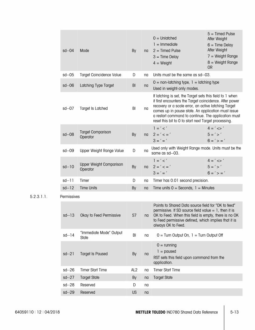
64059110 | 12 | 04/2018 METTLER TOLEDO IND780 Shared Data Reference 5-13
sd--04 Mode By na
0 = Unlatched
1 = Immediate
2 = Timed Pulse
3 = Time Delay
4 = Weight
5 = Timed Pulse After Weight
6 = Time Delay After Weight
7 = Weight Range
8 = Weight Range OR
sd--05 Target Coincidence Value D na Units must be the same as sd--03.
sd--06 Latching Type Target Bl na 0 = non-latching type, 1 = latching type
Used in weight-only modes.
sd--07 Target Is Latched Bl na
If latching is set, the Target sets this field to 1 when it first encounters the Target coincidence. After power recovery or a scale error, an active latching Target comes up in pause state. An application must issue a restart command to continue. The application must reset this bit to 0 to start next Target processing.
sd--08 Target Comparison Operator
By na
1 = ‘ < ‘
2 = ‘ < = ‘
3 = ‘ = ‘
4 = ‘ <> ‘
5 = ‘ > ‘
6 = ‘ > = ‘
sd--09 Upper Weight Range Value D na Used only with Weight Range mode. Units must be the same as sd--03.
sd--10 Upper Weight Comparison Operator
By na
1 = ‘ < ‘
2 = ‘ < = ‘
3 = ‘ = ‘
4 = ‘ <> ‘
5 = ‘ > ‘
6 = ‘ > = ‘
sd--11 Timer D na Timer has 0.01 second precision.
sd--12 Time Units By na Time units 0 = Seconds, 1 = Minutes
5.2.3.1.1. Permissives
sd--13 Okay to Feed Permissive S7 na
Points to Shared Data source field for “OK to feed” permissive. If SD source field value = 1, then it is OK to Feed. When this field is empty, there is no OK to Feed permissive defined, which implies that it is always OK to Feed.
sd--14 “Immediate Mode” Output State Bl na 0 = Turn Output On, 1 = Turn Output Off
sd--21 Target Is Paused By na
0 = running
1 = paused
RST sets this field upon command from the application.
sd--26 Timer Start Time AL2 na Timer Start Time
sd--27 Target State By na Target State
sd--28 Reserved D na
sd--29 Reserved US na
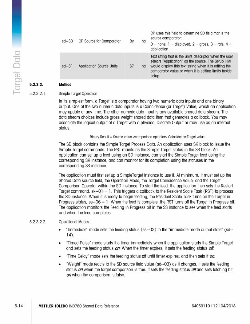
5-14 METTLER TOLEDO IND780 Shared Data Reference 64059110 | 12 | 04/2018
Targ
et D
ata
sd--30 CP Source for Comparator By na
CP uses this field to determine SD field that is the source comparator:
0 = none, 1 = displayed, 2 = gross, 3 = rate, 4 = application
sd--31 Application Source Units S7 na
Text string that is the units descriptor when the user selects “Application” as the source. The Setup HMI would display this text string when it is editing the comparator value or when it is setting limits inside setup.
5.2.3.2. Method
5.2.3.2.1. Simple Target Operation
In its simplest form, a Target is a comparator having two numeric data inputs and one binary output. One of the two numeric data inputs is a Coincidence (or Target) Value, which an application may update at any time. The other numeric data input is any available shared data stream. The data stream choices include gross weight shared data item that generates a callback. You may associate the logical output of a Target with a physical Discrete Output or may use as an internal status.
Binary Result = Source value <comparison operator> Coincidence Target value
The SD block contains the Simple Target Process Data. An application uses SK block to issue the Simple Target commands. The RST maintains the Simple Target status in the SS block. An application can set up a feed using an SD instance, can start the Simple Target feed using the corresponding SK instance, and can monitor for its completion using the statuses in the corresponding SS instance.
The application must first set up a SimpleTarget Instance to use it. At minimum, it must set up the Shared Data source field, the Operation Mode, the Target Coincidence Value, and the Target Comparison Operator within the SD Instance. To start the feed, the application then sets the Restart Target command, sk--01 = 1. This triggers a callback to the Resident Scale Task (RST) to process the SD instance. When it is ready to begin feeding, the Resident Scale Task turns on the Target in Progress status, ss--06 = 1. When the feed is complete, the RST turns off the Target in Progress bit. The application monitors the Feeding in Progress bit in the SS instance to see when the feed starts and when the feed completes.
5.2.3.2.2. Operational Modes
• “Immediate” mode sets the feeding status (ss--03) to the “immediate mode output state” (sd--14).
• “Timed Pulse” mode starts the timer immediately when the application starts the Simple Target and sets the feeding status on. When the timer expires, it sets the feeding status off.
• “Time Delay” mode sets the feeding status off until timer expires, and then sets it on.
• “Weight” mode reacts to the SD source field value (sd--03) as it changes. It sets the feeding status on when the target comparison is true. It sets the feeding status off and sets latching bit on when the comparison is false.
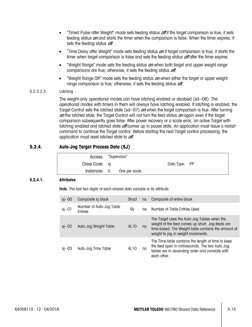
64059110 | 12 | 04/2018 METTLER TOLEDO IND780 Shared Data Reference 5-15
• “Timed Pulse after Weight” mode sets feeding status off if the target comparison is true; it sets feeding status on and starts the timer when the comparison is false. When the timer expires, it sets the feeding status off.
• “Time Delay after Weight” mode sets feeding status on if target comparison is true; it starts the timer when target comparison is false and sets the feeding status off after the timer expires.
• “Weight Range” mode sets the feeding status on when both target and upper weight range comparisons are true; otherwise, it sets the feeding status off.
• “Weight Range OR” mode sets the feeding status on when either the target or upper weight range comparison is true; otherwise, it sets the feeding status off.
5.2.3.2.3. Latching
The weight-only operational modes can have latching enabled or disabled (sd--06). The operational modes with timers in them will always have latching enabled. If latching is enabled, the Target Control sets the latched state (sd--07) on when the target comparison is true. After turning on the latched state, the Target Control will not turn the feed status on again even if the target comparison subsequently goes false. After power recovery or a scale error, an active Target with latching enabled and latched state off comes up in pause state. An application must issue a restart command to continue the Target control. Before starting the next Target control processing, the application must reset latched state to off.
5.2.4. Auto-Jog Target Process Data (SJ)
Access: “Supervisor”
Class Code: sj Data Type: PP
Instances: 5 One per scale.
5.2.4.1. Attributes
Note: The last two digits of each shared data variable is its attribute.
sj--00 Composite sj block Struct na Composite of entire block
sj--01 Number of Auto-Jog Table Entries By na Number of Table Entries Used
sj--02 Auto-Jog Weight Table AL10 na
The Target uses the Auto-Jog Tables when the weight of the feed comes up short. Jog-feeds are time-based. The Weight table contains the amount of weight to jog in weight increments.
sj--03 Auto-Jog Time Table AL10 na
The Time table contains the length of time to keep the feed open in milliseconds. The two Auto-Jog tables are in ascending order and correlate with each other.
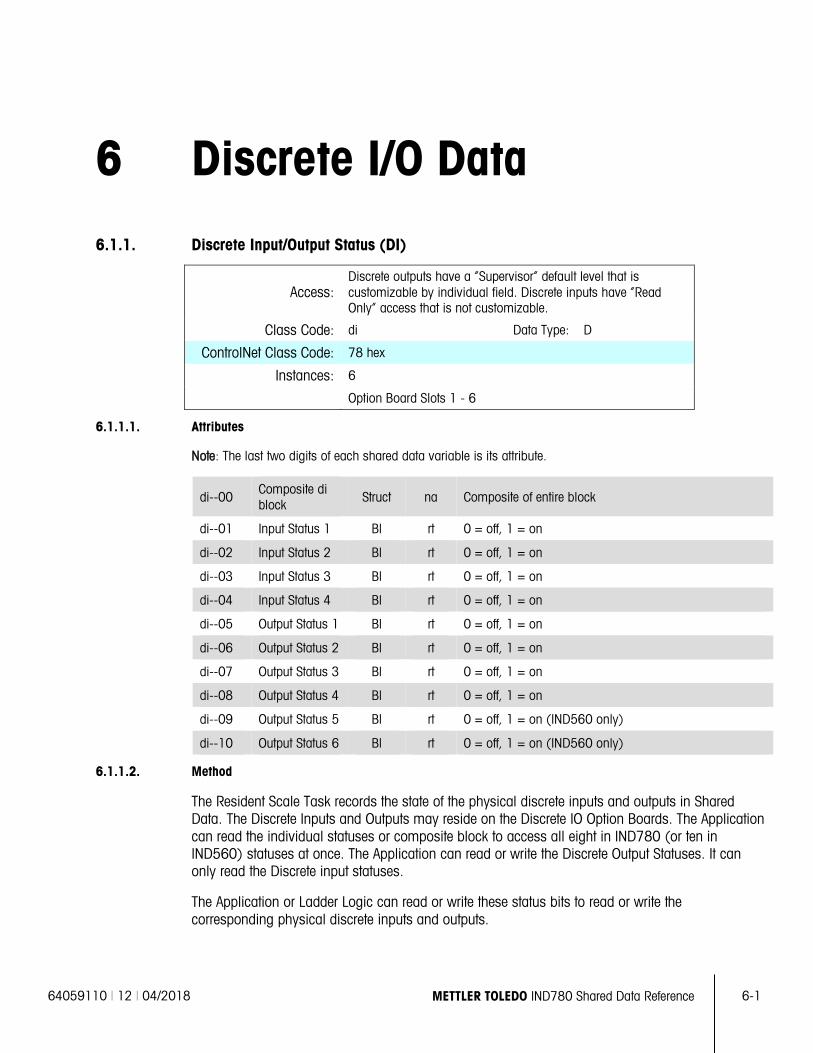
64059110 | 12 | 04/2018 METTLER TOLEDO IND780 Shared Data Reference 6-1
6 Discrete I/O Data
6.1.1. Discrete Input/Output Status (DI)
Access: Discrete outputs have a “Supervisor” default level that is customizable by individual field. Discrete inputs have “Read Only” access that is not customizable.
Class Code: di Data Type: D
ControlNet Class Code: 78 hex
Instances: 6
Option Board Slots 1 - 6
6.1.1.1. Attributes
Note: The last two digits of each shared data variable is its attribute.
di--00 Composite di block Struct na Composite of entire block
di--01 Input Status 1 Bl rt 0 = off, 1 = on
di--02 Input Status 2 Bl rt 0 = off, 1 = on
di--03 Input Status 3 Bl rt 0 = off, 1 = on
di--04 Input Status 4 Bl rt 0 = off, 1 = on
di--05 Output Status 1 Bl rt 0 = off, 1 = on
di--06 Output Status 2 Bl rt 0 = off, 1 = on
di--07 Output Status 3 Bl rt 0 = off, 1 = on
di--08 Output Status 4 Bl rt 0 = off, 1 = on
di--09 Output Status 5 Bl rt 0 = off, 1 = on (IND560 only)
di--10 Output Status 6 Bl rt 0 = off, 1 = on (IND560 only)
6.1.1.2. Method
The Resident Scale Task records the state of the physical discrete inputs and outputs in Shared Data. The Discrete Inputs and Outputs may reside on the Discrete IO Option Boards. The Application can read the individual statuses or composite block to access all eight in IND780 (or ten in IND560) statuses at once. The Application can read or write the Discrete Output Statuses. It can only read the Discrete input statuses.
The Application or Ladder Logic can read or write these status bits to read or write the corresponding physical discrete inputs and outputs.
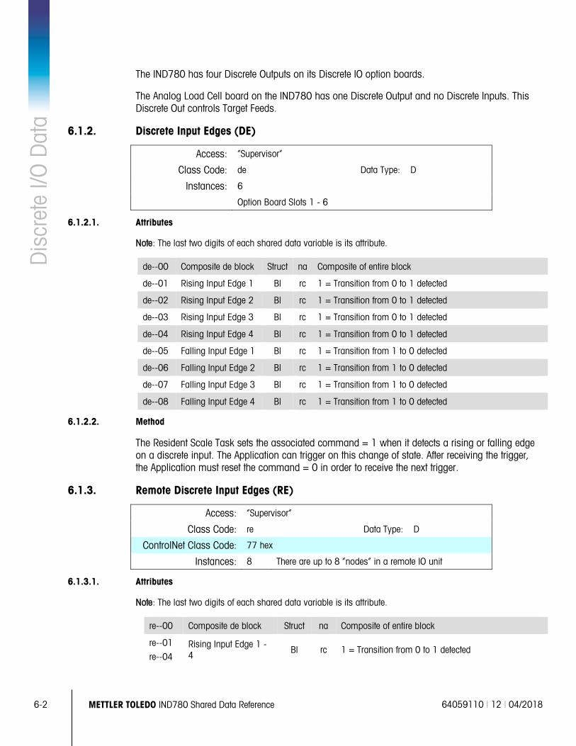
6-2 METTLER TOLEDO IND780 Shared Data Reference 64059110 | 12 | 04/2018
Dis
cret
e I/O
Dat
a The IND780 has four Discrete Outputs on its Discrete IO option boards.
The Analog Load Cell board on the IND780 has one Discrete Output and no Discrete Inputs. This Discrete Out controls Target Feeds.
6.1.2. Discrete Input Edges (DE)
Access: “Supervisor”
Class Code: de Data Type: D
Instances: 6
Option Board Slots 1 - 6
6.1.2.1. Attributes
Note: The last two digits of each shared data variable is its attribute.
de--00 Composite de block Struct na Composite of entire block
de--01 Rising Input Edge 1 Bl rc 1 = Transition from 0 to 1 detected
de--02 Rising Input Edge 2 Bl rc 1 = Transition from 0 to 1 detected
de--03 Rising Input Edge 3 Bl rc 1 = Transition from 0 to 1 detected
de--04 Rising Input Edge 4 Bl rc 1 = Transition from 0 to 1 detected
de--05 Falling Input Edge 1 Bl rc 1 = Transition from 1 to 0 detected
de--06 Falling Input Edge 2 Bl rc 1 = Transition from 1 to 0 detected
de--07 Falling Input Edge 3 Bl rc 1 = Transition from 1 to 0 detected
de--08 Falling Input Edge 4 Bl rc 1 = Transition from 1 to 0 detected
6.1.2.2. Method
The Resident Scale Task sets the associated command = 1 when it detects a rising or falling edge on a discrete input. The Application can trigger on this change of state. After receiving the trigger, the Application must reset the command = 0 in order to receive the next trigger.
6.1.3. Remote Discrete Input Edges (RE)
Access: “Supervisor”
Class Code: re Data Type: D
ControlNet Class Code: 77 hex
Instances: 8 There are up to 8 “nodes” in a remote IO unit
6.1.3.1. Attributes
Note: The last two digits of each shared data variable is its attribute.
re--00 Composite de block Struct na Composite of entire block
re--01
re--04 Rising Input Edge 1 - 4 Bl rc 1 = Transition from 0 to 1 detected
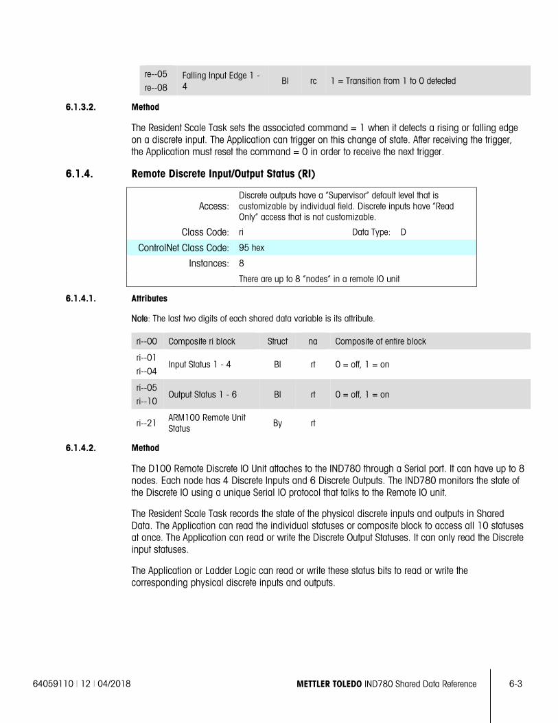
64059110 | 12 | 04/2018 METTLER TOLEDO IND780 Shared Data Reference 6-3
re--05
re--08 Falling Input Edge 1 - 4
Bl rc 1 = Transition from 1 to 0 detected
6.1.3.2. Method
The Resident Scale Task sets the associated command = 1 when it detects a rising or falling edge on a discrete input. The Application can trigger on this change of state. After receiving the trigger, the Application must reset the command = 0 in order to receive the next trigger.
6.1.4. Remote Discrete Input/Output Status (RI)
Access: Discrete outputs have a “Supervisor” default level that is customizable by individual field. Discrete inputs have “Read Only” access that is not customizable.
Class Code: ri Data Type: D
ControlNet Class Code: 95 hex
Instances: 8
There are up to 8 “nodes” in a remote IO unit
6.1.4.1. Attributes
Note: The last two digits of each shared data variable is its attribute.
ri--00 Composite ri block Struct na Composite of entire block
ri--01
ri--04 Input Status 1 - 4 Bl rt 0 = off, 1 = on
ri--05
ri--10 Output Status 1 - 6 Bl rt 0 = off, 1 = on
ri--21 ARM100 Remote Unit Status
By rt
6.1.4.2. Method
The D100 Remote Discrete IO Unit attaches to the IND780 through a Serial port. It can have up to 8 nodes. Each node has 4 Discrete Inputs and 6 Discrete Outputs. The IND780 monitors the state of the Discrete IO using a unique Serial IO protocol that talks to the Remote IO unit.
The Resident Scale Task records the state of the physical discrete inputs and outputs in Shared Data. The Application can read the individual statuses or composite block to access all 10 statuses at once. The Application can read or write the Discrete Output Statuses. It can only read the Discrete input statuses.
The Application or Ladder Logic can read or write these status bits to read or write the corresponding physical discrete inputs and outputs.
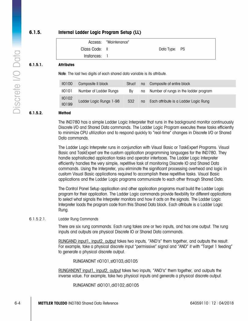
6-4 METTLER TOLEDO IND780 Shared Data Reference 64059110 | 12 | 04/2018
Dis
cret
e I/O
Dat
a 6.1.5. Internal Ladder Logic Program Setup (LL)
Access: “Maintenance”
Class Code: ll Data Type: PS
Instances: 1
6.1.5.1. Attributes
Note: The last two digits of each shared data variable is its attribute.
Il0100 Composite ll block Struct na Composite of entire block
ll0101 Number of Ladder Rungs By na Number of rungs in the ladder program
Il0102
Il0199 Ladder Logic Rungs 1-98 S32 na Each attribute is a Ladder Logic Rung
6.1.5.2. Method
The IND780 has a simple Ladder Logic Interpreter that runs in the background monitor continuously Discrete I/O and Shared Data commands. The Ladder Logic Program executes these tasks efficiently to minimize CPU utilization and to respond quickly to “real-time” changes in Discrete I/O or Shared Data commands.
The Ladder Logic Interpreter runs in conjunction with Visual Basic or TaskExpert Programs. Visual Basic and TaskExpert are the custom application programming languages for the IND780. They handle sophisticated application tasks and operator interfaces. The Ladder Logic Interpreter efficiently handles the very simple, repetitive task of monitoring Discrete IO and Shared Data commands. Using the Interpreter, you eliminate the significant processing overhead and logic in custom Visual Basic applications required to accomplish these repetitive tasks. Visual Basic applications and the Ladder Logic programs communicate to each other through Shared Data.
The Control Panel Setup application and other application programs must build the Ladder Logic program for their application. The Ladder Logic commands provide flexibility for different applications to select what signals the Interpreter monitors and how it acts on the signals. The Ladder Logic Interpreter loads the program code from this Shared Data block. Each attribute is a Ladder Logic Rung.
6.1.5.2.1. Ladder Rung Commands
There are six rung commands. Each rung takes one or two inputs, and has one output. The rung inputs and outputs are physical Discrete IO or Shared Data commands.
RUNGAND input1, input2, output takes two inputs, “AND’s” them together, and outputs the result. For example, take a physical discrete input “permissive” signal and “AND” it with “Target 1 feeding” to generate a physical discrete output.
RUNGANDNT ri0101,st0103,di0105
RUNGANDNT input1, input2, output takes two inputs, “AND’s” them together, and outputs the inverse value. For example, take two physical inputs and generate a physical discrete output.
RUNGANDNT di0101,di0102,di0105
64059110 | 12 | 04/2018 METTLER TOLEDO IND780 Shared Data Reference 6-5
RUNGMOV input, output takes an input and generates an output with the same value. For example, take a tare on Scale 2 when a physical discrete input goes on.
RUNGMOV di0103,wc0201
RUNGMVNOT input, output moves the inverse of the input to the output. For example, turn on a physical discrete output when the data from Scale 1 is invalid.
RUNGMVNOT wx0138,di0108
RUNGOR input1, input2, output takes two inputs, OR’s them together, and outputs the result. For example, turn on a physical discrete output if Scale 1 or Scale 2 is in motion.
RUNGOR wx0131,wx0231,di0508
RUNGORNOT input1, input2, output takes two inputs, OR’s them together, and outputs the inverse value.
For example, turn on a physical discrete output when either the custom application turns off an application status or a physical discrete input is off.
RUNGORNOT as0101,di0103,di0505
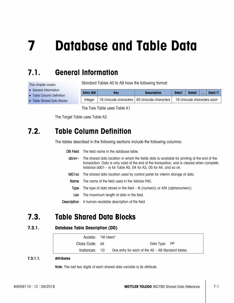
64059110 | 12 | 04/2018 METTLER TOLEDO IND780 Shared Data Reference 7-1
This chapter covers
• General Information
• Table Column Definition
• Table Shared Data Blocks
7 Database and Table Data
7.1. General Information Standard Tables A0 to A9 have the following format:
Entry ID# Key Description Data1 Data2 … Data17
Integer 16 Unicode characters 40 Unicode characters 16 Unicode characters each
The Tare Table uses Table A1.
The Target Table uses Table A2.
7.2. Table Column Definition The tables described in the following sections include the following columns:
DB Field The field name in the database table.
ddnn-- The shared data location in which the fields data is available for printing at the end of the transaction. Data is only valid at the end of the transaction, and is cleared when complete. Instance dd01-- is for Table A0, 04 for A3, 05 for A4, and so on.
td01xx The shared data location used by control panel for interim storage of data.
Name The name of the field used in the Vehicle PAC.
Type The type of data stored in the field – N (numeric) or A/N (alphanumeric).
Len The maximum length of data in the field.
Description A human-readable description of the field
7.3. Table Shared Data Blocks 7.3.1. Database Table Description (DD)
Access: “All Users”
Class Code: dd Data Type: PP
Instances: 10 One entry for each of the A0 – A9 Standard tables.
7.3.1.1. Attributes
Note: The last two digits of each shared data variable is its attribute.
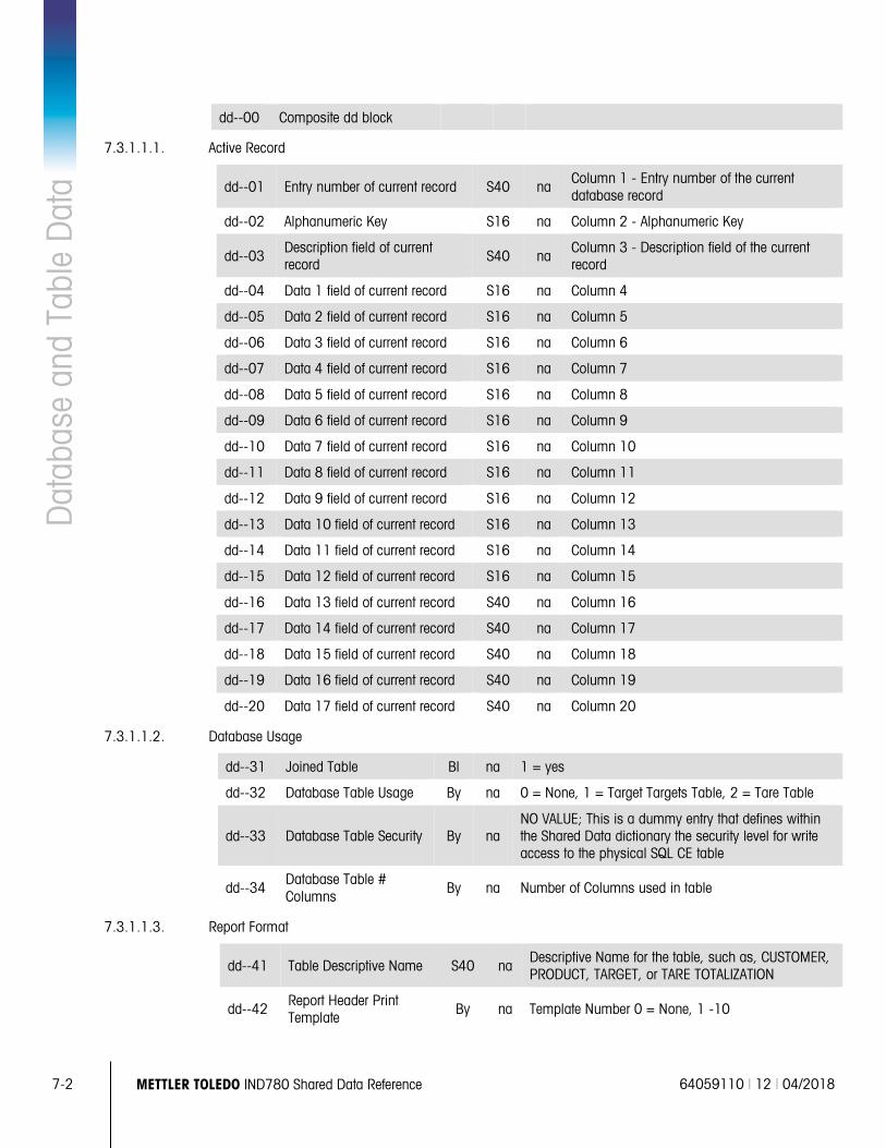
7-2 METTLER TOLEDO IND780 Shared Data Reference 64059110 | 12 | 04/2018
Dat
abas
e an
d Ta
ble
Dat
a dd--00 Composite dd block
7.3.1.1.1. Active Record
dd--01 Entry number of current record S40 na Column 1 - Entry number of the current database record
dd--02 Alphanumeric Key S16 na Column 2 - Alphanumeric Key
dd--03 Description field of current record S40 na
Column 3 - Description field of the current record
dd--04 Data 1 field of current record S16 na Column 4
dd--05 Data 2 field of current record S16 na Column 5
dd--06 Data 3 field of current record S16 na Column 6
dd--07 Data 4 field of current record S16 na Column 7
dd--08 Data 5 field of current record S16 na Column 8
dd--09 Data 6 field of current record S16 na Column 9
dd--10 Data 7 field of current record S16 na Column 10
dd--11 Data 8 field of current record S16 na Column 11
dd--12 Data 9 field of current record S16 na Column 12
dd--13 Data 10 field of current record S16 na Column 13
dd--14 Data 11 field of current record S16 na Column 14
dd--15 Data 12 field of current record S16 na Column 15
dd--16 Data 13 field of current record S40 na Column 16
dd--17 Data 14 field of current record S40 na Column 17
dd--18 Data 15 field of current record S40 na Column 18
dd--19 Data 16 field of current record S40 na Column 19
dd--20 Data 17 field of current record S40 na Column 20
7.3.1.1.2. Database Usage
dd--31 Joined Table Bl na 1 = yes
dd--32 Database Table Usage By na 0 = None, 1 = Target Targets Table, 2 = Tare Table
dd--33 Database Table Security By na NO VALUE; This is a dummy entry that defines within the Shared Data dictionary the security level for write access to the physical SQL CE table
dd--34 Database Table # Columns
By na Number of Columns used in table
7.3.1.1.3. Report Format
dd--41 Table Descriptive Name S40 na Descriptive Name for the table, such as, CUSTOMER, PRODUCT, TARGET, or TARE TOTALIZATION
dd--42 Report Header Print Template
By na Template Number 0 = None, 1 -10
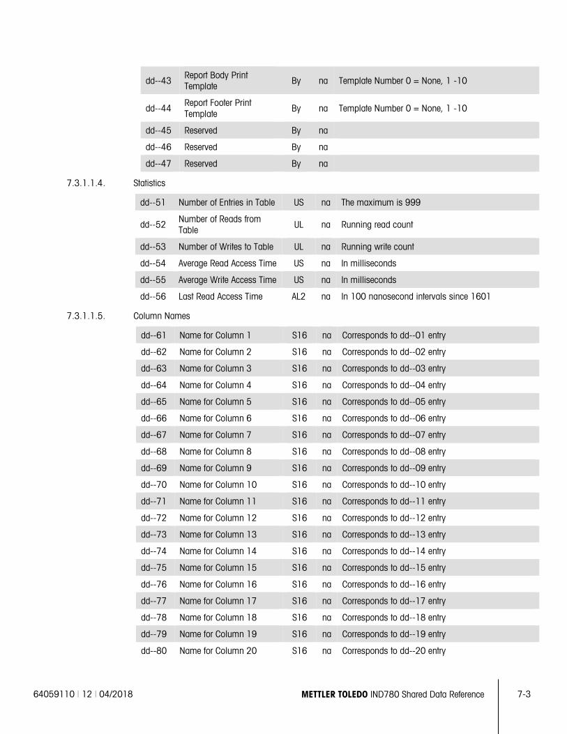
64059110 | 12 | 04/2018 METTLER TOLEDO IND780 Shared Data Reference 7-3
dd--43 Report Body Print Template By na Template Number 0 = None, 1 -10
dd--44 Report Footer Print Template
By na Template Number 0 = None, 1 -10
dd--45 Reserved By na
dd--46 Reserved By na
dd--47 Reserved By na
7.3.1.1.4. Statistics
dd--51 Number of Entries in Table US na The maximum is 999
dd--52 Number of Reads from Table UL na Running read count
dd--53 Number of Writes to Table UL na Running write count
dd--54 Average Read Access Time US na In milliseconds
dd--55 Average Write Access Time US na In milliseconds
dd--56 Last Read Access Time AL2 na In 100 nanosecond intervals since 1601
7.3.1.1.5. Column Names
dd--61 Name for Column 1 S16 na Corresponds to dd--01 entry
dd--62 Name for Column 2 S16 na Corresponds to dd--02 entry
dd--63 Name for Column 3 S16 na Corresponds to dd--03 entry
dd--64 Name for Column 4 S16 na Corresponds to dd--04 entry
dd--65 Name for Column 5 S16 na Corresponds to dd--05 entry
dd--66 Name for Column 6 S16 na Corresponds to dd--06 entry
dd--67 Name for Column 7 S16 na Corresponds to dd--07 entry
dd--68 Name for Column 8 S16 na Corresponds to dd--08 entry
dd--69 Name for Column 9 S16 na Corresponds to dd--09 entry
dd--70 Name for Column 10 S16 na Corresponds to dd--10 entry
dd--71 Name for Column 11 S16 na Corresponds to dd--11 entry
dd--72 Name for Column 12 S16 na Corresponds to dd--12 entry
dd--73 Name for Column 13 S16 na Corresponds to dd--13 entry
dd--74 Name for Column 14 S16 na Corresponds to dd--14 entry
dd--75 Name for Column 15 S16 na Corresponds to dd--15 entry
dd--76 Name for Column 16 S16 na Corresponds to dd--16 entry
dd--77 Name for Column 17 S16 na Corresponds to dd--17 entry
dd--78 Name for Column 18 S16 na Corresponds to dd--18 entry
dd--79 Name for Column 19 S16 na Corresponds to dd--19 entry
dd--80 Name for Column 20 S16 na Corresponds to dd--20 entry
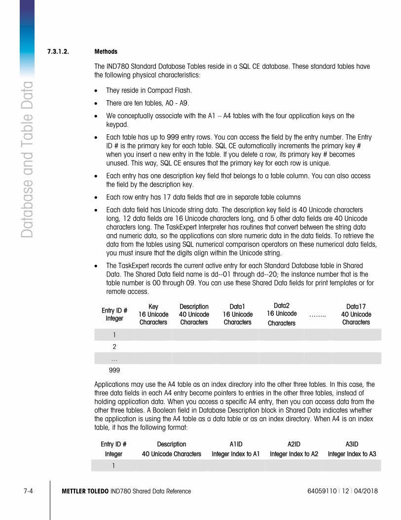
7-4 METTLER TOLEDO IND780 Shared Data Reference 64059110 | 12 | 04/2018
Dat
abas
e an
d Ta
ble
Dat
a 7.3.1.2. Methods
The IND780 Standard Database Tables reside in a SQL CE database. These standard tables have the following physical characteristics:
• They reside in Compact Flash.
• There are ten tables, A0 - A9.
• We conceptually associate with the A1 – A4 tables with the four application keys on the keypad.
• Each table has up to 999 entry rows. You can access the field by the entry number. The Entry ID # is the primary key for each table. SQL CE automatically increments the primary key # when you insert a new entry in the table. If you delete a row, its primary key # becomes unused. This way, SQL CE ensures that the primary key for each row is unique.
• Each entry has one description key field that belongs to a table column. You can also access the field by the description key.
• Each row entry has 17 data fields that are in separate table columns
• Each data field has Unicode string data. The description key field is 40 Unicode characters long, 12 data fields are 16 Unicode characters long, and 5 other data fields are 40 Unicode characters long. The TaskExpert Interpreter has routines that convert between the string data and numeric data, so the applications can store numeric data in the data fields. To retrieve the data from the tables using SQL numerical comparison operators on these numerical data fields, you must insure that the digits align within the Unicode string.
• The TaskExpert records the current active entry for each Standard Database table in Shared Data. The Shared Data field name is dd--01 through dd--20; the instance number that is the table number is 00 through 09. You can use these Shared Data fields for print templates or for remote access.
Entry ID # Integer
Key 16 Unicode Characters
Description 40 Unicode Characters
Data1 16 Unicode Characters
Data2 16 Unicode
Characters ……..
Data17 40 Unicode Characters
1
2
…
999
Applications may use the A4 table as an index directory into the other three tables. In this case, the three data fields in each A4 entry become pointers to entries in the other three tables, instead of holding application data. When you access a specific A4 entry, then you can access data from the other three tables. A Boolean field in Database Description block in Shared Data indicates whether the application is using the A4 table as a data table or as an index directory. When A4 is an index table, it has the following format:
Entry ID #
Integer
Description
40 Unicode Characters
A1ID
Integer Index to A1
A2ID
Integer Index to A2
A3ID
Integer Index to A3
1
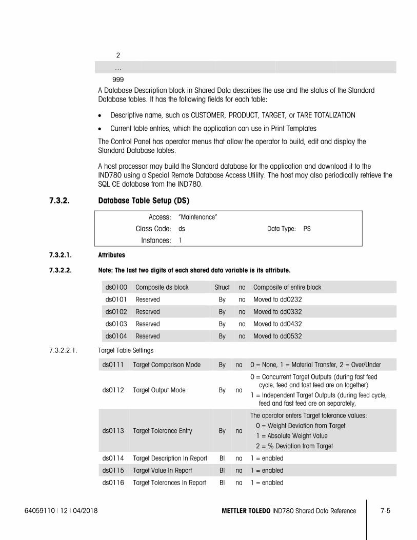
64059110 | 12 | 04/2018 METTLER TOLEDO IND780 Shared Data Reference 7-5
2
…
999
A Database Description block in Shared Data describes the use and the status of the Standard Database tables. It has the following fields for each table:
• Descriptive name, such as CUSTOMER, PRODUCT, TARGET, or TARE TOTALIZATION
• Current table entries, which the application can use in Print Templates
The Control Panel has operator menus that allow the operator to build, edit and display the Standard Database tables.
A host processor may build the Standard database for the application and download it to the IND780 using a Special Remote Database Access Utility. The host may also periodically retrieve the SQL CE database from the IND780.
7.3.2. Database Table Setup (DS)
Access: “Maintenance”
Class Code: ds Data Type: PS
Instances: 1
7.3.2.1. Attributes
7.3.2.2. Note: The last two digits of each shared data variable is its attribute.
ds0100 Composite ds block Struct na Composite of entire block
ds0101 Reserved By na Moved to dd0232
ds0102 Reserved By na Moved to dd0332
ds0103 Reserved By na Moved to dd0432
ds0104 Reserved By na Moved to dd0532
7.3.2.2.1. Target Table Settings
ds0111 Target Comparison Mode By na 0 = None, 1 = Material Transfer, 2 = Over/Under
ds0112 Target Output Mode By na
0 = Concurrent Target Outputs (during fast feed cycle, feed and fast feed are on together)
1 = Independent Target Outputs (during feed cycle, feed and fast feed are on separately,
ds0113 Target Tolerance Entry By na
The operator enters Target tolerance values:
0 = Weight Deviation from Target
1 = Absolute Weight Value
2 = % Deviation from Target
ds0114 Target Description In Report Bl na 1 = enabled
ds0115 Target Value In Report Bl na 1 = enabled
ds0116 Target Tolerances In Report Bl na 1 = enabled
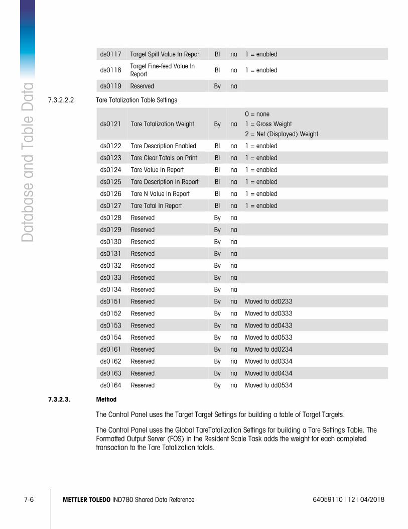
7-6 METTLER TOLEDO IND780 Shared Data Reference 64059110 | 12 | 04/2018
Dat
abas
e an
d Ta
ble
Dat
a ds0117 Target Spill Value In Report Bl na 1 = enabled
ds0118 Target Fine-feed Value In Report Bl na 1 = enabled
ds0119 Reserved By na
7.3.2.2.2. Tare Totalization Table Settings
ds0121 Tare Totalization Weight By na
0 = none
1 = Gross Weight
2 = Net (Displayed) Weight
ds0122 Tare Description Enabled Bl na 1 = enabled
ds0123 Tare Clear Totals on Print Bl na 1 = enabled
ds0124 Tare Value In Report Bl na 1 = enabled
ds0125 Tare Description In Report Bl na 1 = enabled
ds0126 Tare N Value In Report Bl na 1 = enabled
ds0127 Tare Total In Report Bl na 1 = enabled
ds0128 Reserved By na
ds0129 Reserved By na
ds0130 Reserved By na
ds0131 Reserved By na
ds0132 Reserved By na
ds0133 Reserved By na
ds0134 Reserved By na
ds0151 Reserved By na Moved to dd0233
ds0152 Reserved By na Moved to dd0333
ds0153 Reserved By na Moved to dd0433
ds0154 Reserved By na Moved to dd0533
ds0161 Reserved By na Moved to dd0234
ds0162 Reserved By na Moved to dd0334
ds0163 Reserved By na Moved to dd0434
ds0164 Reserved By na Moved to dd0534
7.3.2.3. Method
The Control Panel uses the Target Target Settings for building a table of Target Targets.
The Control Panel uses the Global TareTotalization Settings for building a Tare Settings Table. The Formatted Output Server (FOS) in the Resident Scale Task adds the weight for each completed transaction to the Tare Totalization totals.
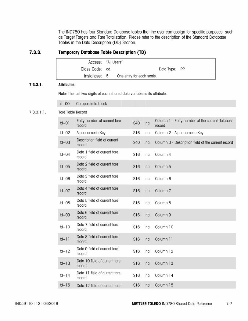
64059110 | 12 | 04/2018 METTLER TOLEDO IND780 Shared Data Reference 7-7
The IND780 has four Standard Database tables that the user can assign for specific purposes, such as Target Targets and Tare Totalization. Please refer to the description of the Standard Database Tables in the Data Description (DD) Section.
7.3.3. Temporary Database Table Description (TD)
Access: “All Users”
Class Code: dd Data Type: PP
Instances: 5 One entry for each scale.
7.3.3.1. Attributes
Note: The last two digits of each shared data variable is its attribute.
td--00 Composite td block
7.3.3.1.1. Tare Table Record
td--01 Entry number of current tare record S40 na
Column 1 - Entry number of the current database record
td--02 Alphanumeric Key S16 na Column 2 - Alphanumeric Key
td--03 Description field of current record S40 na Column 3 - Description field of the current record
td--04 Data 1 field of current tare record
S16 na Column 4
td--05 Data 2 field of current tare record S16 na Column 5
td--06 Data 3 field of current tare record
S16 na Column 6
td--07 Data 4 field of current tare record S16 na Column 7
td--08 Data 5 field of current tare record
S16 na Column 8
td--09 Data 6 field of current tare record S16 na Column 9
td--10 Data 7 field of current tare record
S16 na Column 10
td--11 Data 8 field of current tare record S16 na Column 11
td--12 Data 9 field of current tare record
S16 na Column 12
td--13 Data 10 field of current tare record S16 na Column 13
td--14 Data 11 field of current tare record
S16 na Column 14
td--15 Data 12 field of current tare S16 na Column 15
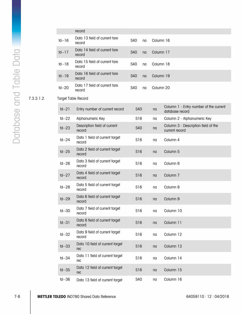
7-8 METTLER TOLEDO IND780 Shared Data Reference 64059110 | 12 | 04/2018
Dat
abas
e an
d Ta
ble
Dat
a record
td--16 Data 13 field of current tare record S40 na Column 16
td--17 Data 14 field of current tare record
S40 na Column 17
td--18 Data 15 field of current tare record S40 na Column 18
td--19 Data 16 field of current tare record
S40 na Column 19
td--20 Data 17 field of current tare record S40 na Column 20
7.3.3.1.2. Target Table Record
td--21 Entry number of current record S40 na Column 1 - Entry number of the current database record
td--22 Alphanumeric Key S16 na Column 2 - Alphanumeric Key
td--23 Description field of current record
S40 na Column 3 - Description field of the current record
td--24 Data 1 field of current target record S16 na Column 4
td--25 Data 2 field of current target record
S16 na Column 5
td--26 Data 3 field of current target record S16 na Column 6
td--27 Data 4 field of current target record
S16 na Column 7
td--28 Data 5 field of current target record S16 na Column 8
td--29 Data 6 field of current target record
S16 na Column 9
td--30 Data 7 field of current target record S16 na Column 10
td--31 Data 8 field of current target record
S16 na Column 11
td--32 Data 9 field of current target record S16 na Column 12
td--33 Data 10 field of current target rec
S16 na Column 13
td--34 Data 11 field of current target rec S16 na Column 14
td--35 Data 12 field of current target rec
S16 na Column 15
td--36 Data 13 field of current target S40 na Column 16
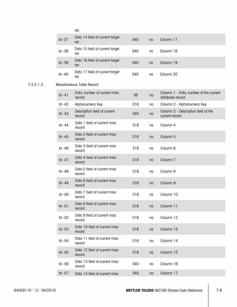
64059110 | 12 | 04/2018 METTLER TOLEDO IND780 Shared Data Reference 7-9
rec
td--37 Data 14 field of current target rec S40 na Column 17
td--38 Data 15 field of current target rec
S40 na Column 18
td--39 Data 16 field of current target rec S40 na Column 19
td--40 Data 17 field of current target rec
S40 na Column 20
7.3.3.1.3. Miscellaneous Table Record
td--41 Entry number of current misc record
S8 na Column 1 - Entry number of the current database record
td--42 Alphanumeric Key S16 na Column 2 - Alphanumeric Key
td--43 Description field of current record S40 na
Column 3 - Description field of the current record
td--44 Data 1 field of current misc record
S16 na Column 4
td--45 Data 2 field of current misc record S16 na Column 5
td--46 Data 3 field of current misc record
S16 na Column 6
td--47 Data 4 field of current misc record S16 na Column 7
td--48 Data 5 field of current misc record
S16 na Column 8
td--49 Data 6 field of current misc record S16 na Column 9
td--50 Data 7 field of current misc record
S16 na Column 10
td--51 Data 8 field of current misc record S16 na Column 11
td--52 Data 9 field of current misc record
S16 na Column 12
td--53 Data 10 field of current misc record S16 na Column 13
td--54 Data 11 field of current misc record
S16 na Column 14
td--55 Data 12 field of current misc record S16 na Column 15
td--56 Data 13 field of current misc record
S40 na Column 16
td--57 Data 14 field of current misc S40 na Column 17
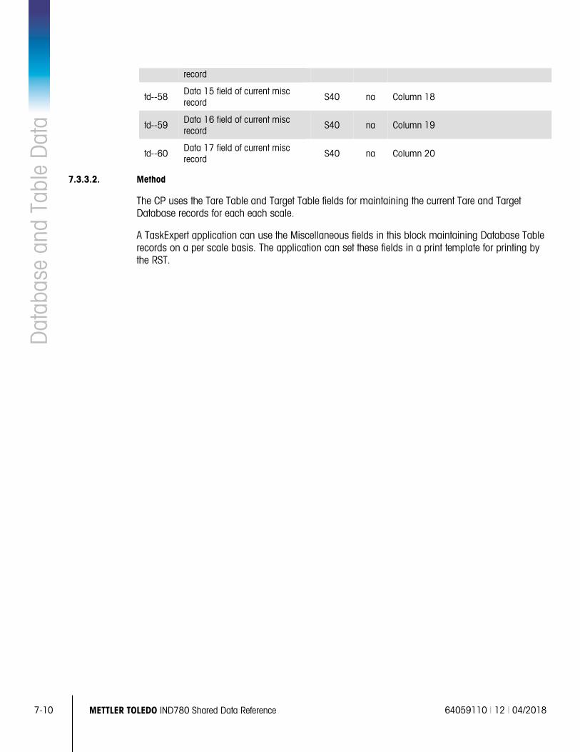
7-10 METTLER TOLEDO IND780 Shared Data Reference 64059110 | 12 | 04/2018
Dat
abas
e an
d Ta
ble
Dat
a record
td--58 Data 15 field of current misc record S40 na Column 18
td--59 Data 16 field of current misc record
S40 na Column 19
td--60 Data 17 field of current misc record S40 na Column 20
7.3.3.2. Method
The CP uses the Tare Table and Target Table fields for maintaining the current Tare and Target Database records for each each scale.
A TaskExpert application can use the Miscellaneous fields in this block maintaining Database Table records on a per scale basis. The application can set these fields in a print template for printing by the RST.
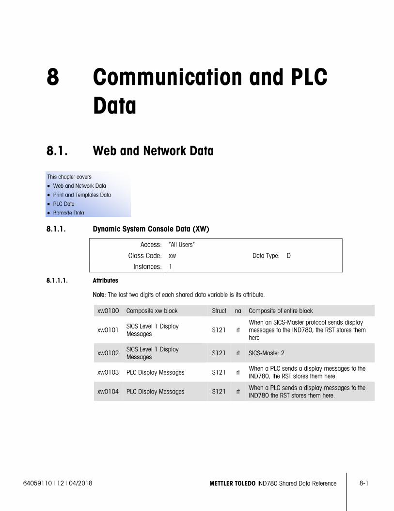
64059110 | 12 | 04/2018 METTLER TOLEDO IND780 Shared Data Reference 8-1
This chapter covers
• Web and Network Data
• Print and Templates Data
• PLC Data
• Barcode Data
8 Communication and PLC Data
8.1. Web and Network Data
8.1.1. Dynamic System Console Data (XW)
Access: “All Users”
Class Code: xw Data Type: D
Instances: 1
8.1.1.1. Attributes
Note: The last two digits of each shared data variable is its attribute.
xw0100 Composite xw block Struct na Composite of entire block
xw0101 SICS Level 1 Display Messages
S121 rt When an SICS-Master protocol sends display messages to the IND780, the RST stores them here
xw0102 SICS Level 1 Display Messages
S121 rt SICS-Master 2
xw0103 PLC Display Messages S121 rt When a PLC sends a display messages to the IND780, the RST stores them here.
xw0104 PLC Display Messages S121 rt When a PLC sends a display messages to the IND780 the RST stores them here.
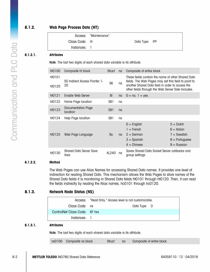
8-2 METTLER TOLEDO IND780 Shared Data Reference 64059110 | 12 | 04/2018
Com
mun
icat
ion
and
PLC
Dat
a 8.1.2. Web Page Process Data (HT)
Access: “Maintenance”
Class Code: ht Data Type: PP
Instances: 1
8.1.2.1. Attributes
Note: The last two digits of each shared data variable is its attribute.
ht0100 Composite ht block Struct na Composite of entire block
ht0101 SD Indirect Access Pointer 1-20
S6 na
These fields contain the name of other Shared Data fields. The Web Pages may set this field to point to another Shared Data field in order to access the other fields through the Web Server Side Includes.
ht0120
ht0121 Enable Web Server Bl na 0 = no, 1 = yes.
ht0122 Home Page location S81 na
ht0123 Documentation Page location
S81 na
ht0124 Help Page location S81 na
ht0125 Web Page Language By na
0 = English
1 = French
2 = German
3 = Spanish
4 = Chinese
5 = Dutch
6 = Italian
7 = Swedish
8 = Portuguese
9 = Russian
ht0130 Shared Data Server Save Area
AL240 na Saves Shared Data Socket Server callbacks and group settings
8.1.2.2. Method
The Web Pages can use Alias Names for accessing Shared Data names. It provides one level of indirection for reading Shared Data. This mechanism allows the Web Pages to store names of the Shared Data fields it is monitoring in Shared Data fields ht0101 through ht0120. Then, it can read the fields indirectly by reading the Alias names, hc0101 through hc0120.
8.1.3. Network Node Status (NS)
Access: “Read Only.” Access level is not customizable.
Class Code: ns Data Type: D
ControlNet Class Code: 6F hex
Instances: 1
8.1.3.1. Attributes
Note: The last two digits of each shared data variable is its attribute.
ns0100 Composite ns block Struct na Composite of entire block
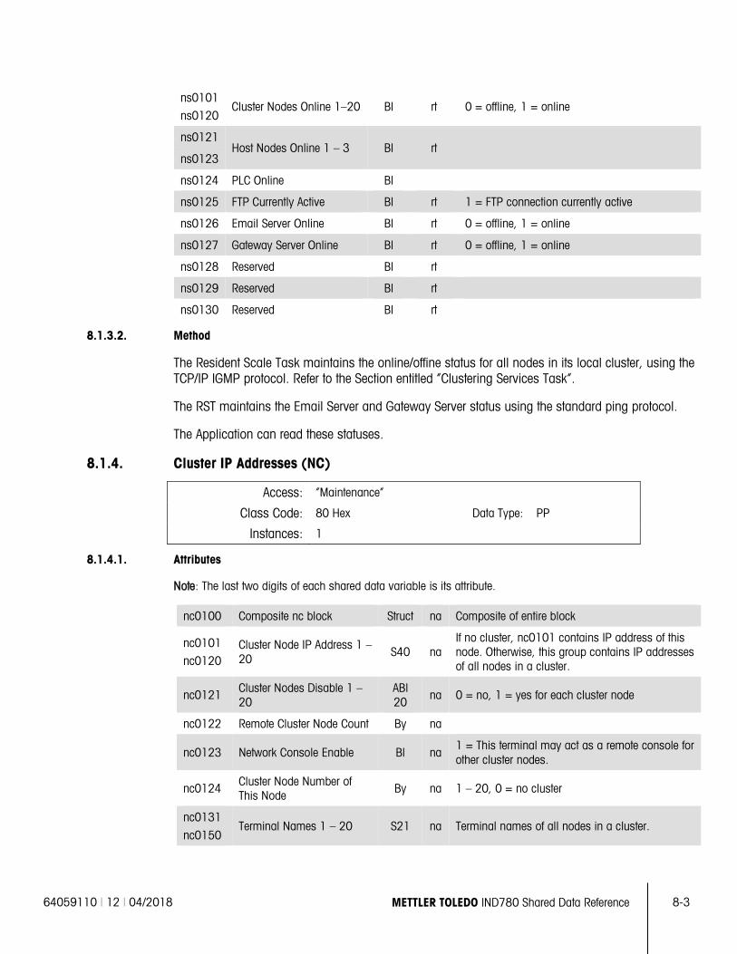
64059110 | 12 | 04/2018 METTLER TOLEDO IND780 Shared Data Reference 8-3
ns0101
ns0120 Cluster Nodes Online 1–20 Bl rt 0 = offline, 1 = online
ns0121 Host Nodes Online 1 – 3 Bl rt
ns0123
ns0124 PLC Online Bl
ns0125 FTP Currently Active Bl rt 1 = FTP connection currently active
ns0126 Email Server Online Bl rt 0 = offline, 1 = online
ns0127 Gateway Server Online Bl rt 0 = offline, 1 = online
ns0128 Reserved Bl rt
ns0129 Reserved Bl rt
ns0130 Reserved Bl rt
8.1.3.2. Method
The Resident Scale Task maintains the online/offine status for all nodes in its local cluster, using the TCP/IP IGMP protocol. Refer to the Section entitled “Clustering Services Task”.
The RST maintains the Email Server and Gateway Server status using the standard ping protocol.
The Application can read these statuses.
8.1.4. Cluster IP Addresses (NC)
Access: “Maintenance”
Class Code: 80 Hex Data Type: PP
Instances: 1
8.1.4.1. Attributes
Note: The last two digits of each shared data variable is its attribute.
nc0100 Composite nc block Struct na Composite of entire block
nc0101
nc0120 Cluster Node IP Address 1 – 20
S40 na If no cluster, nc0101 contains IP address of this node. Otherwise, this group contains IP addresses of all nodes in a cluster.
nc0121 Cluster Nodes Disable 1 – 20
ABl 20
na 0 = no, 1 = yes for each cluster node
nc0122 Remote Cluster Node Count By na
nc0123 Network Console Enable Bl na 1 = This terminal may act as a remote console for other cluster nodes.
nc0124 Cluster Node Number of This Node
By na 1 – 20, 0 = no cluster
nc0131
nc0150 Terminal Names 1 – 20 S21 na Terminal names of all nodes in a cluster.
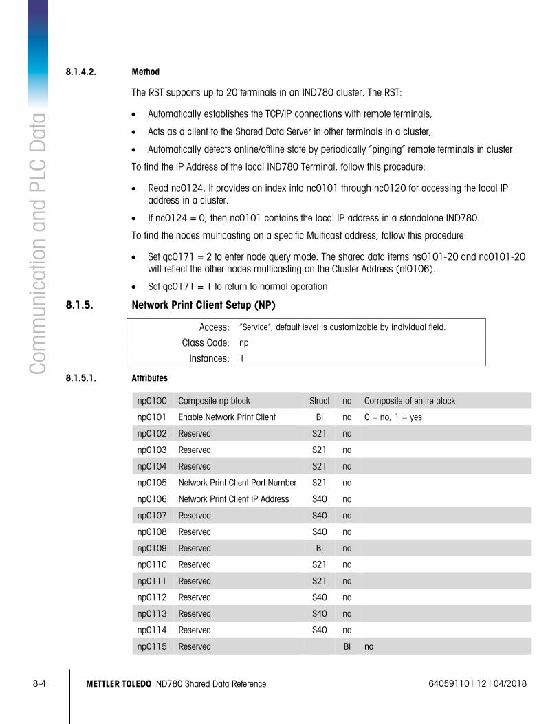
8-4 METTLER TOLEDO IND780 Shared Data Reference 64059110 | 12 | 04/2018
Com
mun
icat
ion
and
PLC
Dat
a 8.1.4.2. Method
The RST supports up to 20 terminals in an IND780 cluster. The RST:
• Automatically establishes the TCP/IP connections with remote terminals,
• Acts as a client to the Shared Data Server in other terminals in a cluster,
• Automatically detects online/offline state by periodically “pinging” remote terminals in cluster.
To find the IP Address of the local IND780 Terminal, follow this procedure:
• Read nc0124. It provides an index into nc0101 through nc0120 for accessing the local IP address in a cluster.
• If nc0124 = 0, then nc0101 contains the local IP address in a standalone IND780.
To find the nodes multicasting on a specific Multicast address, follow this procedure:
• Set qc0171 = 2 to enter node query mode. The shared data items ns0101-20 and nc0101-20 will reflect the other nodes multicasting on the Cluster Address (nt0106).
• Set qc0171 = 1 to return to normal operation.
8.1.5. Network Print Client Setup (NP)
Access: “Service”, default level is customizable by individual field.
Class Code: np
Instances: 1
8.1.5.1. Attributes
np0100 Composite np block Struct na Composite of entire block
np0101 Enable Network Print Client Bl na 0 = no, 1 = yes
np0102 Reserved S21 na
np0103 Reserved S21 na
np0104 Reserved S21 na
np0105 Network Print Client Port Number S21 na
np0106 Network Print Client IP Address S40 na
np0107 Reserved S40 na
np0108 Reserved S40 na
np0109 Reserved Bl na
np0110 Reserved S21 na
np0111 Reserved S21 na
np0112 Reserved S40 na
np0113 Reserved S40 na
np0114 Reserved S40 na
np0115 Reserved Bl na
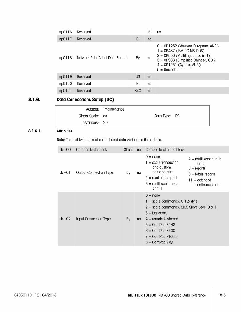
64059110 | 12 | 04/2018 METTLER TOLEDO IND780 Shared Data Reference 8-5
np0116 Reserved Bl na
np0117 Reserved Bl na
np0118 Network Print Client Data Format By na
0 = CP1252 (Western European, ANSI) 1 = CP437 (IBM PC MS-DOS) 2 = CP850 (Multilingual, Latin 1) 3 = CP936 (Simplified Chinese, GBK) 4 = CP1251 (Cyrillic, ANSI) 5 = Unicode
np0119 Reserved US na
np0120 Reserved Bl na
np0121 Reserved S40 na
8.1.6. Data Connections Setup (DC)
Access: “Maintenance”
Class Code: dc Data Type: PS
Instances: 20
8.1.6.1. Attributes
Note: The last two digits of each shared data variable is its attribute.
dc--00 Composite dc block Struct na Composite of entire block
dc--01 Output Connection Type By na
0 = none
1 = scale transaction and custom demand print
2 = continuous print
3 = multi-continuous print 1
4 = multi-continuous print 2
5 = reports
6 = totals reports
11 = extended continuous print
dc--02 Input Connection Type By na
0 = none
1 = scale commands, CTPZ-style
2 = scale commands, SICS Slave Level 0 & 1,
3 = bar codes
4 = remote keyboard
5 = ComPac 8142
6 = ComPac 8530
7 = ComPac PT6S3
8 = ComPac SMA
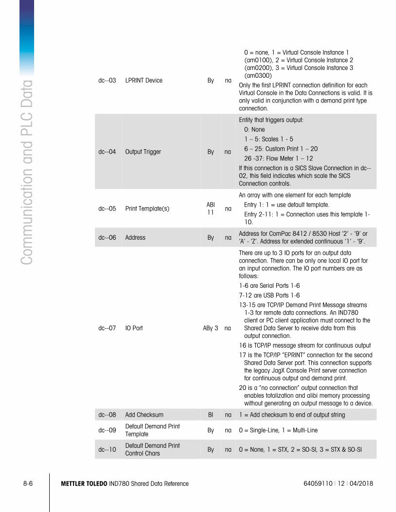
8-6 METTLER TOLEDO IND780 Shared Data Reference 64059110 | 12 | 04/2018
Com
mun
icat
ion
and
PLC
Dat
a dc--03 LPRINT Device By na
0 = none, 1 = Virtual Console Instance 1 (am0100), 2 = Virtual Console Instance 2 (am0200), 3 = Virtual Console Instance 3 (am0300)
Only the first LPRINT connection definition for each Virtual Console in the Data Connections is valid. It is only valid in conjunction with a demand print type connection.
dc--04 Output Trigger By na
Entity that triggers output:
0: None
1 – 5: Scales 1 - 5
6 – 25: Custom Print 1 – 20
26 -37: Flow Meter 1 – 12
If this connection is a SICS Slave Connection in dc--02, this field indicates which scale the SICS Connection controls.
dc--05 Print Template(s) ABl 11 na
An array with one element for each template
Entry 1: 1 = use default template.
Entry 2-11: 1 = Connection uses this template 1-10.
dc--06 Address By na Address for ComPac 8412 / 8530 Host ‘2’ - ‘9’ or ‘A’ - ‘Z’. Address for extended continuous ‘1’ - ‘9’.
dc--07 IO Port ABy 3 na
There are up to 3 IO ports for an output data connection. There can be only one local IO port for an input connection. The IO port numbers are as follows:
1-6 are Serial Ports 1-6
7-12 are USB Ports 1-6
13-15 are TCP/IP Demand Print Message streams 1-3 for remote data connections. An IND780 client or PC client application must connect to the Shared Data Server to receive data from this output connection.
16 is TCP/IP message stream for continuous output
17 is the TCP/IP “EPRINT” connection for the second Shared Data Server port. This connection supports the legacy JagX Console Print server connection for continuous output and demand print.
20 is a “no connection” output connection that enables totalization and alibi memory processing without generating an output message to a device.
dc--08 Add Checksum Bl na 1 = Add checksum to end of output string
dc--09 Default Demand Print Template
By na 0 = Single-Line, 1 = Multi-Line
dc--10 Default Demand Print Control Chars By na 0 = None, 1 = STX, 2 = SO-SI, 3 = STX & SO-SI
64059110 | 12 | 04/2018 METTLER TOLEDO IND780 Shared Data Reference 8-7
8.1.6.2. Method
You can establish Data Connections to Serial Ports, USB Ports, and TCP/IP Connection Ports. There is a separate instance of the DC class for each data connection. You may only specify a single output type OR a single input type in each connection instance – not both. A SICS command connection is an exception; it is both and input and an output connection.
Here are some rules for configuring data connections:
• Demand print and Continuous print connections CANNOT share the same IO port.
• An input connection CANNOT share the same IO port with another input connection.
• Multiple demand print and custom print connections CAN share the same IO port.
• Demand OR Continuous print connections CAN share an IO port with a single Input-only connection, such as CTPZ-command connection or a bar-code reader connection.
• A SICS-connection must have exclusive use of its IO port since it does bi-directional IO.
• Multiple ComPac 8142 or 8530 hosts (not both) may share the same port if their addresses are unique.
• Scales and Remote Discrete IO devices must have exclusive use of their IO port.
• You can configure multiple continuous print connections to a single IO port. However, the RST only sends the data from a single “selected” scale at a time.
• Custom applications must have exclusive use of their IO ports for communicating bi-directionally with a custom device. However, they CAN share a port with demand print and custom print connections when the application is doing output-only operations.
• Only the first LPRINT connection definition is valid.
• Only the first Continuous Standard connection for each scale is valid.
• Only the first Continuous Template connection for each scale is valid. The maximum length of Template Continuous Output string is 200 characters.
• Only the first Continuous Multiplexed connection is valid.
The RST uses the “Output Trigger” parameter for determining which device or command can trigger the print operations for the connection. Shared Data commands for each device initiate the demand or continuous print operations. Shared Data commands trigger the custom print operations.
The TCP/IP Console Print Server enables one or more remote client programs to receive print data from the IND780. The remote clients can be WINDOWS PC Visual Basic applications or other TCP/IP host programs. You must first enable the TCP/IP Console Print Server Print Connection. Then, whenever a remote client establishes a TCP/IP connection, the Console Print Server sends the LPRINT data, the demand and custom print data, and the console log data to the client across the TCP/IP connection to the remote client. The Console Print Server uses TCP/IP port 1701 for establishing connections.
The IND780 Console Print Server sends only the specific output selected by the Output Connection and LPRINT device parameters in the TCP/IP data connection instances.
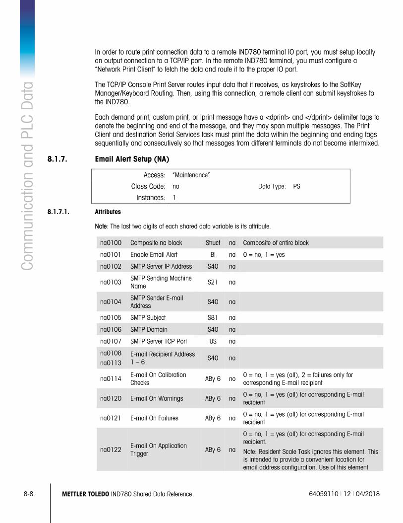
8-8 METTLER TOLEDO IND780 Shared Data Reference 64059110 | 12 | 04/2018
Com
mun
icat
ion
and
PLC
Dat
a In order to route print connection data to a remote IND780 terminal IO port, you must setup locally an output connection to a TCP/IP port. In the remote IND780 terminal, you must configure a “Network Print Client” to fetch the data and route it to the proper IO port.
The TCP/IP Console Print Server routes input data that it receives, as keystrokes to the SoftKey Manager/Keyboard Routing. Then, using this connection, a remote client can submit keystrokes to the IND780.
Each demand print, custom print, or lprint message have a <dprint> and </dprint> delimiter tags to denote the beginning and end of the message, and they may span multiple messages. The Print Client and destination Serial Services task must print the data within the beginning and ending tags sequentially and consecutively so that messages from different terminals do not become intermixed.
8.1.7. Email Alert Setup (NA)
Access: “Maintenance”
Class Code: na Data Type: PS
Instances: 1
8.1.7.1. Attributes
Note: The last two digits of each shared data variable is its attribute.
na0100 Composite na block Struct na Composite of entire block
na0101 Enable Email Alert Bl na 0 = no, 1 = yes
na0102 SMTP Server IP Address S40 na
na0103 SMTP Sending Machine Name
S21 na
na0104 SMTP Sender E-mail Address
S40 na
na0105 SMTP Subject S81 na
na0106 SMTP Domain S40 na
na0107 SMTP Server TCP Port US na
na0108
na0113 E-mail Recipient Address 1 – 6
S40 na
na0114 E-mail On Calibration Checks
ABy 6 no 0 = no, 1 = yes (all), 2 = failures only for corresponding E-mail recipient
na0120 E-mail On Warnings ABy 6 na 0 = no, 1 = yes (all) for corresponding E-mail recipient
na0121 E-mail On Failures ABy 6 na 0 = no, 1 = yes (all) for corresponding E-mail recipient
na0122 E-mail On Application Trigger ABy 6 na
0 = no, 1 = yes (all) for corresponding E-mail recipient.
Note: Resident Scale Task ignores this element. This is intended to provide a convenient location for email address configuration. Use of this element
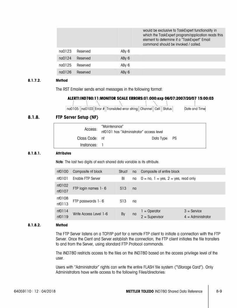
64059110 | 12 | 04/2018 METTLER TOLEDO IND780 Shared Data Reference 8-9
would be exclusive to TaskExpert functionality in which the TaskExpert program/application reads this element to determine if a “TaskExpert” Email command should be invoked / called.
na0123 Reserved ABy 6
na0124 Reserved ABy 6
na0125 Reserved ABy 6
na0126 Reserved ABy 6
8.1.7.2. Method
The RST Emailer sends email messages in the following format:
8.1.8. FTP Server Setup (NF)
Access: “Maintenance” nf0101 has “Administrator” access level
Class Code: nf Data Type: PS
Instances: 1
8.1.8.1. Attributes
Note: The last two digits of each shared data variable is its attribute.
nf0100 Composite nf block Struct na Composite of entire block
nf0101 Enable FTP Server Bl na 0 = no, 1 = yes, 2 = yes, read only
nf0102
nf0107 FTP login names 1- 6 S13 na
nf0108
nf0113 FTP passwords 1- 6 S13 na
nf0114
nf0119 Write Access Level 1-6 By na
1 = Operator
2 = Supervisor
3 = Service
4 = Administrator
8.1.8.2. Method
The FTP Server listens on a TCP/IP port for a remote FTP client to initiate a connection with the FTP Server. Once the Cient and Server establish the connection, the FTP client initiates the file transfers to and from the Server, using standard FTP Protocol commands.
The IND780 restricts access to the files on the IND780 based on the access privilege level of the user.
Users with “Administrator” rights can write the entire FLASH file system (“\Storage Card”). Only Administrators have write access to the following Files/directories:
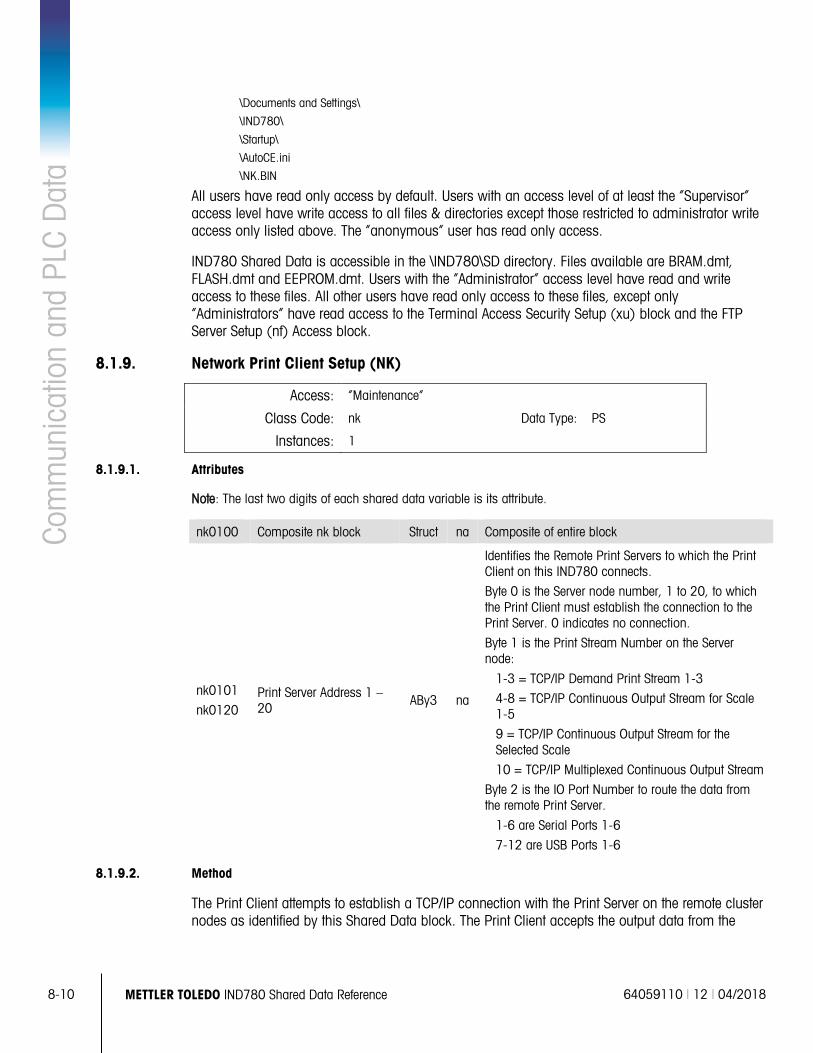
8-10 METTLER TOLEDO IND780 Shared Data Reference 64059110 | 12 | 04/2018
Com
mun
icat
ion
and
PLC
Dat
a \Documents and Settings\
\IND780\
\Startup\
\AutoCE.ini
\NK.BIN
All users have read only access by default. Users with an access level of at least the “Supervisor” access level have write access to all files & directories except those restricted to administrator write access only listed above. The “anonymous” user has read only access.
IND780 Shared Data is accessible in the \IND780\SD directory. Files available are BRAM.dmt, FLASH.dmt and EEPROM.dmt. Users with the “Administrator” access level have read and write access to these files. All other users have read only access to these files, except only “Administrators” have read access to the Terminal Access Security Setup (xu) block and the FTP Server Setup (nf) Access block.
8.1.9. Network Print Client Setup (NK)
Access: “Maintenance”
Class Code: nk Data Type: PS
Instances: 1
8.1.9.1. Attributes
Note: The last two digits of each shared data variable is its attribute.
nk0100 Composite nk block Struct na Composite of entire block
nk0101
nk0120 Print Server Address 1 – 20
ABy3 na
Identifies the Remote Print Servers to which the Print Client on this IND780 connects.
Byte 0 is the Server node number, 1 to 20, to which the Print Client must establish the connection to the Print Server. 0 indicates no connection.
Byte 1 is the Print Stream Number on the Server node:
1-3 = TCP/IP Demand Print Stream 1-3
4-8 = TCP/IP Continuous Output Stream for Scale 1-5
9 = TCP/IP Continuous Output Stream for the Selected Scale
10 = TCP/IP Multiplexed Continuous Output Stream
Byte 2 is the IO Port Number to route the data from the remote Print Server.
1-6 are Serial Ports 1-6
7-12 are USB Ports 1-6
8.1.9.2. Method
The Print Client attempts to establish a TCP/IP connection with the Print Server on the remote cluster nodes as identified by this Shared Data block. The Print Client accepts the output data from the
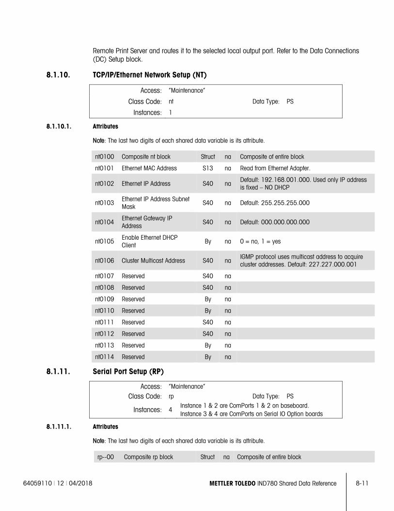
64059110 | 12 | 04/2018 METTLER TOLEDO IND780 Shared Data Reference 8-11
Remote Print Server and routes it to the selected local output port. Refer to the Data Connections (DC) Setup block.
8.1.10. TCP/IP/Ethernet Network Setup (NT)
Access: “Maintenance”
Class Code: nt Data Type: PS
Instances: 1
8.1.10.1. Attributes
Note: The last two digits of each shared data variable is its attribute.
nt0100 Composite nt block Struct na Composite of entire block
nt0101 Ethernet MAC Address S13 na Read from Ethernet Adapter.
nt0102 Ethernet IP Address S40 na Default: 192.168.001.000. Used only IP address is fixed – NO DHCP
nt0103 Ethernet IP Address Subnet Mask
S40 na Default: 255.255.255.000
nt0104 Ethernet Gateway IP Address S40 na Default: 000.000.000.000
nt0105 Enable Ethernet DHCP Client
By na 0 = no, 1 = yes
nt0106 Cluster Multicast Address S40 na IGMP protocol uses multicast address to acquire cluster addresses. Default: 227.227.000.001
nt0107 Reserved S40 na
nt0108 Reserved S40 na
nt0109 Reserved By na
nt0110 Reserved By na
nt0111 Reserved S40 na
nt0112 Reserved S40 na
nt0113 Reserved By na
nt0114 Reserved By na
8.1.11. Serial Port Setup (RP)
Access: “Maintenance”
Class Code: rp Data Type: PS
Instances: 4 Instance 1 & 2 are ComPorts 1 & 2 on baseboard. Instance 3 & 4 are ComPorts on Serial IO Option boards
8.1.11.1. Attributes
Note: The last two digits of each shared data variable is its attribute.
rp--00 Composite rp block Struct na Composite of entire block
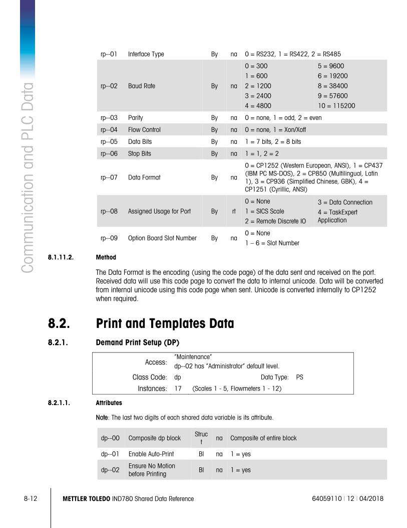
8-12 METTLER TOLEDO IND780 Shared Data Reference 64059110 | 12 | 04/2018
Com
mun
icat
ion
and
PLC
Dat
a rp--01 Interface Type By na 0 = RS232, 1 = RS422, 2 = RS485
rp--02 Baud Rate By na
0 = 300
1 = 600
2 = 1200
3 = 2400
4 = 4800
5 = 9600
6 = 19200
8 = 38400
9 = 57600
10 = 115200
rp--03 Parity By na 0 = none, 1 = odd, 2 = even
rp--04 Flow Control By na 0 = none, 1 = Xon/Xoff
rp--05 Data Bits By na 1 = 7 bits, 2 = 8 bits
rp--06 Stop Bits By na 1 = 1, 2 = 2
rp--07 Data Format By na
0 = CP1252 (Western European, ANSI), 1 = CP437 (IBM PC MS-DOS), 2 = CP850 (Multilingual, Latin 1), 3 = CP936 (Simplified Chinese, GBK), 4 = CP1251 (Cyrillic, ANSI)
rp--08 Assigned Usage for Port By rt
0 = None
1 = SICS Scale
2 = Remote Discrete IO
3 = Data Connection
4 = TaskExpert Application
rp--09 Option Board Slot Number By na 0 = None
1 – 6 = Slot Number
8.1.11.2. Method
The Data Format is the encoding (using the code page) of the data sent and received on the port. Received data will use this code page to convert the data to internal unicode. Data will be converted from internal unicode using this code page when sent. Unicode is converted internally to CP1252 when required.
8.2. Print and Templates Data 8.2.1. Demand Print Setup (DP)
Access: “Maintenance” dp--02 has “Administrator” default level.
Class Code: dp Data Type: PS
Instances: 17 (Scales 1 - 5, Flowmeters 1 - 12)
8.2.1.1. Attributes
Note: The last two digits of each shared data variable is its attribute.
dp--00 Composite dp block Struct
na Composite of entire block
dp--01 Enable Auto-Print Bl na 1 = yes
dp--02 Ensure No Motion before Printing
Bl na 1 = yes
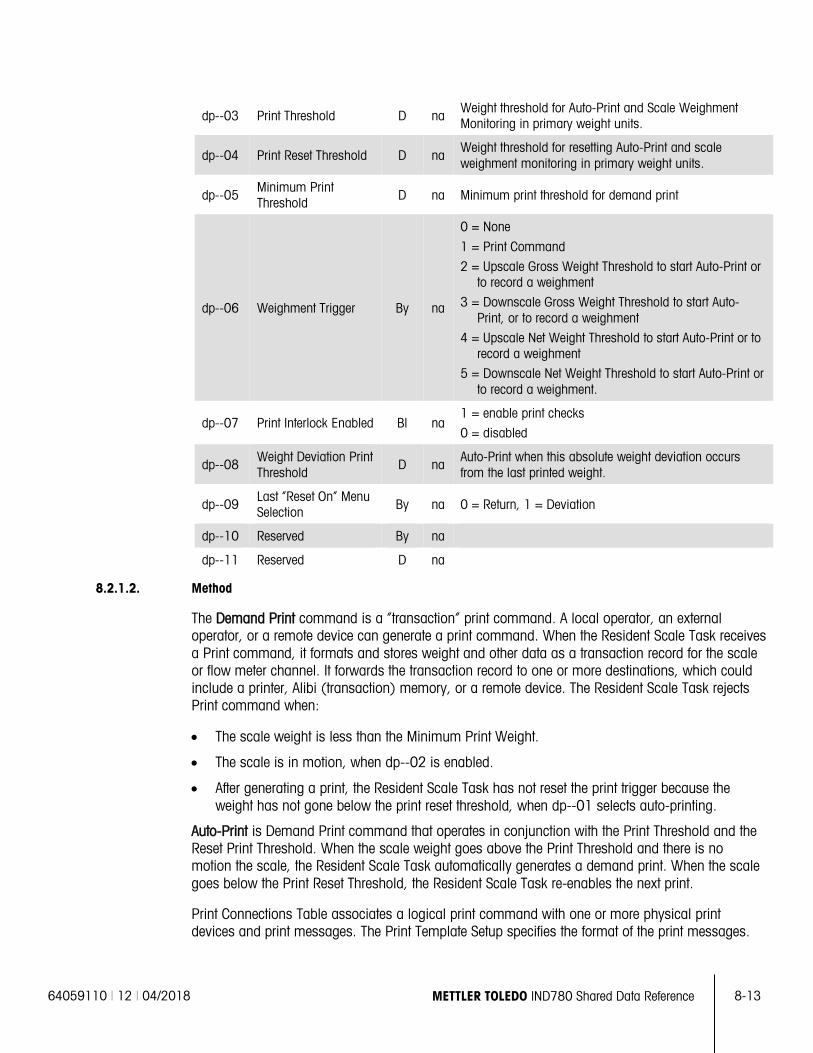
64059110 | 12 | 04/2018 METTLER TOLEDO IND780 Shared Data Reference 8-13
dp--03 Print Threshold D na Weight threshold for Auto-Print and Scale Weighment Monitoring in primary weight units.
dp--04 Print Reset Threshold D na Weight threshold for resetting Auto-Print and scale weighment monitoring in primary weight units.
dp--05 Minimum Print Threshold D na Minimum print threshold for demand print
dp--06 Weighment Trigger By na
0 = None
1 = Print Command
2 = Upscale Gross Weight Threshold to start Auto-Print or to record a weighment
3 = Downscale Gross Weight Threshold to start Auto-Print, or to record a weighment
4 = Upscale Net Weight Threshold to start Auto-Print or to record a weighment
5 = Downscale Net Weight Threshold to start Auto-Print or to record a weighment.
dp--07 Print Interlock Enabled Bl na 1 = enable print checks
0 = disabled
dp--08 Weight Deviation Print Threshold
D na Auto-Print when this absolute weight deviation occurs from the last printed weight.
dp--09 Last “Reset On” Menu Selection By na 0 = Return, 1 = Deviation
dp--10 Reserved By na
dp--11 Reserved D na
8.2.1.2. Method
The Demand Print command is a “transaction” print command. A local operator, an external operator, or a remote device can generate a print command. When the Resident Scale Task receives a Print command, it formats and stores weight and other data as a transaction record for the scale or flow meter channel. It forwards the transaction record to one or more destinations, which could include a printer, Alibi (transaction) memory, or a remote device. The Resident Scale Task rejects Print command when:
• The scale weight is less than the Minimum Print Weight.
• The scale is in motion, when dp--02 is enabled.
• After generating a print, the Resident Scale Task has not reset the print trigger because the weight has not gone below the print reset threshold, when dp--01 selects auto-printing.
Auto-Print is Demand Print command that operates in conjunction with the Print Threshold and the Reset Print Threshold. When the scale weight goes above the Print Threshold and there is no motion the scale, the Resident Scale Task automatically generates a demand print. When the scale goes below the Print Reset Threshold, the Resident Scale Task re-enables the next print.
Print Connections Table associates a logical print command with one or more physical print devices and print messages. The Print Template Setup specifies the format of the print messages.
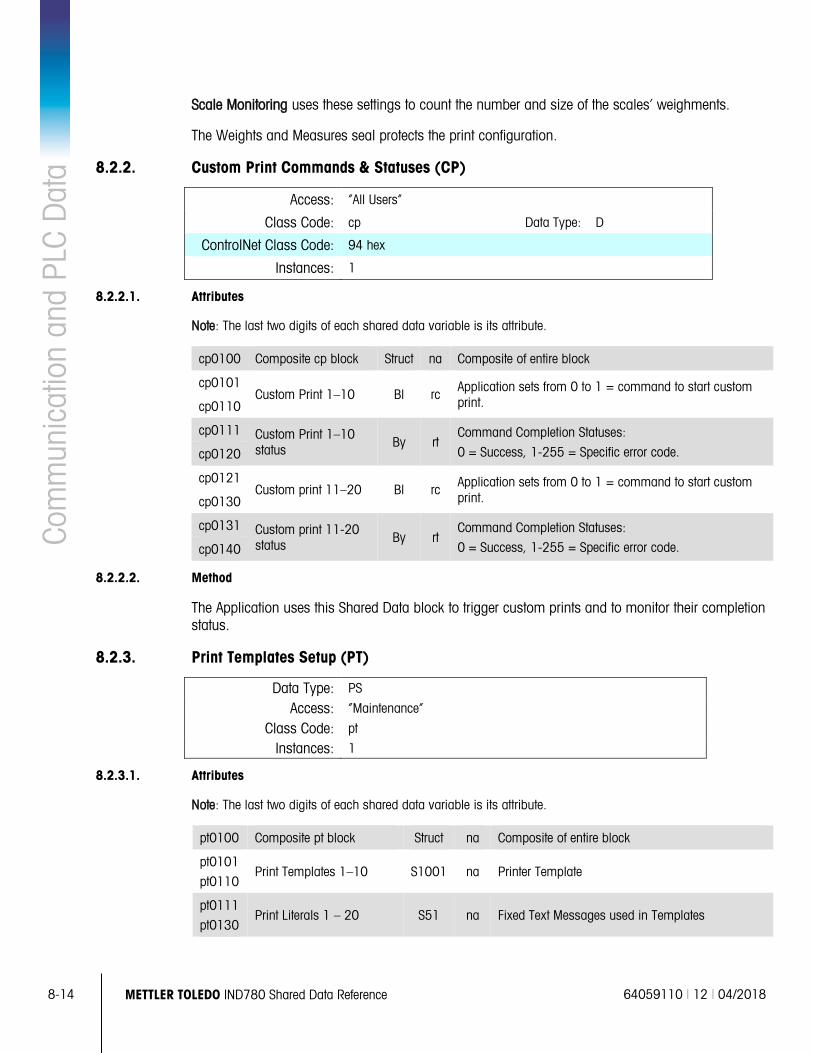
8-14 METTLER TOLEDO IND780 Shared Data Reference 64059110 | 12 | 04/2018
Com
mun
icat
ion
and
PLC
Dat
a Scale Monitoring uses these settings to count the number and size of the scales’ weighments.
The Weights and Measures seal protects the print configuration.
8.2.2. Custom Print Commands & Statuses (CP)
Access: “All Users”
Class Code: cp Data Type: D
ControlNet Class Code: 94 hex
Instances: 1
8.2.2.1. Attributes
Note: The last two digits of each shared data variable is its attribute.
cp0100 Composite cp block Struct na Composite of entire block
cp0101 Custom Print 1–10 Bl rc Application sets from 0 to 1 = command to start custom
print. cp0110
cp0111 Custom Print 1–10 status By rt
Command Completion Statuses:
0 = Success, 1-255 = Specific error code. cp0120
cp0121 Custom print 11–20 Bl rc Application sets from 0 to 1 = command to start custom
print. cp0130
cp0131 Custom print 11-20 status By rt
Command Completion Statuses:
0 = Success, 1-255 = Specific error code. cp0140
8.2.2.2. Method
The Application uses this Shared Data block to trigger custom prints and to monitor their completion status.
8.2.3. Print Templates Setup (PT)
Data Type: PS
Access: “Maintenance”
Class Code: pt
Instances: 1
8.2.3.1. Attributes
Note: The last two digits of each shared data variable is its attribute.
pt0100 Composite pt block Struct na Composite of entire block
pt0101
pt0110 Print Templates 1–10 S1001 na Printer Template
pt0111
pt0130 Print Literals 1 – 20 S51 na Fixed Text Messages used in Templates
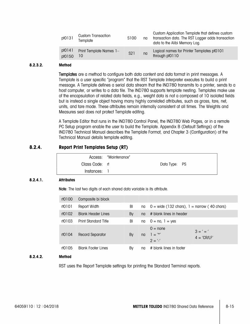
64059110 | 12 | 04/2018 METTLER TOLEDO IND780 Shared Data Reference 8-15
pt0131 Custom Transaction Template
S100 na Custom Application Template that defines custom transaction data. The RST Logger adds transaction data to the Alibi Memory Log.
pt0141
pt0150 Print Template Names 1–10 S21 na
Logical names for Printer Templates pt0101 through pt0110
8.2.3.2. Method
Templates are a method to configure both data content and data format in print messages. A Template is a user specific “program” that the RST Template Interpreter executes to build a print message. A Template defines a serial data stream that the IND780 transmits to a printer, sends to a host computer, or writes to a data file. The IND780 supports template nesting. Templates make use of the encapsulation of related data fields, e.g., weight data is not a composed of 10 isolated fields but is instead a single object having many highly correlated attributes, such as gross, tare, net, units, and tare mode. These attributes remain internally consistent at all times. The Weights and Measures seal does not protect Template editing.
A Template Editor that runs in the IND780 Control Panel, the IND780 Web Pages, or in a remote PC Setup program enable the user to build the Template. Appendix B (Default Settings) of the IND780 Technical Manual describes the Template Format, and Chapter 3 (Configuration) of the Technical Manual details template editing.
8.2.4. Report Print Templates Setup (RT)
Access: “Maintenance”
Class Code: rt Data Type: PS
Instances: 1
8.2.4.1. Attributes
Note: The last two digits of each shared data variable is its attribute.
rt0100 Composite bi block
rt0101 Report Width Bl na 0 = wide (132 chars), 1 = narrow ( 40 chars)
rt0102 Blank Header Lines By na # blank lines in header
rt0103 Print Standard Title Bl na 0 = no, 1 = yes
rt0104 Record Separator By na
0 = none
1 = ‘*’
2 = ‘-‘
3 = ‘ = ’
4 = ‘CR/LF’
rt0105 Blank Footer Lines By na # blank lines in footer
8.2.4.2. Method
RST uses the Report Template settings for printing the Standard Terminal reports.
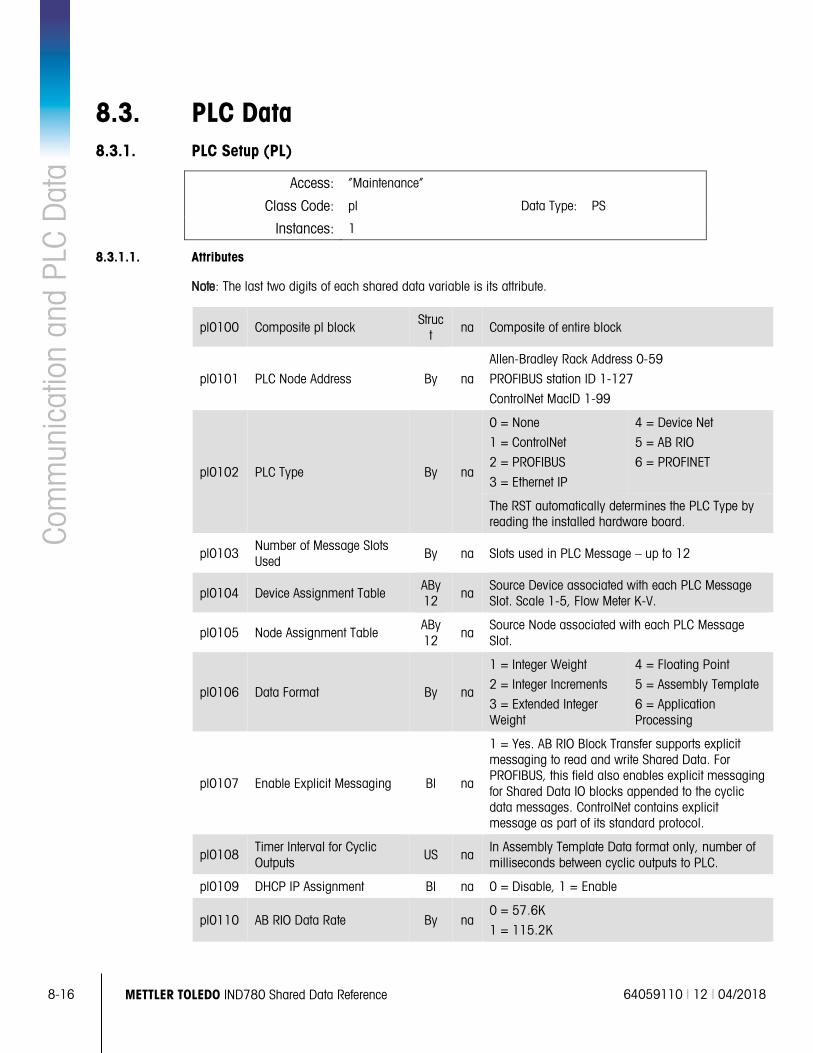
8-16 METTLER TOLEDO IND780 Shared Data Reference 64059110 | 12 | 04/2018
Com
mun
icat
ion
and
PLC
Dat
a
8.3. PLC Data 8.3.1. PLC Setup (PL)
Access: “Maintenance”
Class Code: pl Data Type: PS
Instances: 1
8.3.1.1. Attributes
Note: The last two digits of each shared data variable is its attribute.
pl0100 Composite pl block Struct
na Composite of entire block
pl0101 PLC Node Address By na
Allen-Bradley Rack Address 0-59
PROFIBUS station ID 1-127
ControlNet MacID 1-99
pl0102 PLC Type By na
0 = None
1 = ControlNet
2 = PROFIBUS
3 = Ethernet IP
4 = Device Net
5 = AB RIO
6 = PROFINET
The RST automatically determines the PLC Type by reading the installed hardware board.
pl0103 Number of Message Slots Used
By na Slots used in PLC Message – up to 12
pl0104 Device Assignment Table ABy 12 na
Source Device associated with each PLC Message Slot. Scale 1-5, Flow Meter K-V.
pl0105 Node Assignment Table ABy 12
na Source Node associated with each PLC Message Slot.
pl0106 Data Format By na
1 = Integer Weight
2 = Integer Increments
3 = Extended Integer Weight
4 = Floating Point
5 = Assembly Template
6 = Application Processing
pl0107 Enable Explicit Messaging Bl na
1 = Yes. AB RIO Block Transfer supports explicit messaging to read and write Shared Data. For PROFIBUS, this field also enables explicit messaging for Shared Data IO blocks appended to the cyclic data messages. ControlNet contains explicit message as part of its standard protocol.
pl0108 Timer Interval for Cyclic Outputs
US na In Assembly Template Data format only, number of milliseconds between cyclic outputs to PLC.
pl0109 DHCP IP Assignment Bl na 0 = Disable, 1 = Enable
pl0110 AB RIO Data Rate By na 0 = 57.6K
1 = 115.2K
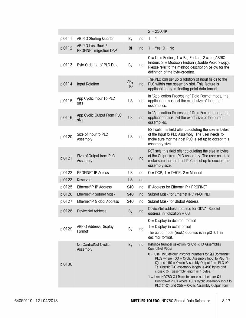
64059110 | 12 | 04/2018 METTLER TOLEDO IND780 Shared Data Reference 8-17
2 = 230.4K
pl0111 AB RIO Starting Quarter By na 1 – 4
pl0112 AB RIO Last Rack / PROFINET migration DAP
Bl na 1 = Yes, 0 = No
pl0113 Byte-Ordering of PLC Data By na
0 = Little Endian, 1 = Big Endian, 2 = JagABRIO Endian, 3 = Modicon Endian (Double Word Swap). Please refer to the method description below for the definition of the byte-ordering.
pl0114 Input Rotation ABy 10
na The PLC can set up a rotation of input fields to the PLC within one assembly slot. This feature is applicable only in floating point data format.
pl0115 App Cyclic Input To PLC size
US na In “Application Processing” Data Format mode, the application must set the exact size of the input assemblies.
pl0116 App Cyclic Output From PLC size US na
In “Application Processing” Data Format mode, the application must set the exact size of the output assemblies.
pl0120 Size of Input to PLC Assembly
US na
RST sets this field after calculating the size in bytes of the Input to PLC Assembly. The user needs to make sure that the host PLC is set up to accept this assembly size.
pl0121 Size of Output from PLC Assembly
US na
RST sets this field after calculating the size in bytes of the Output from PLC Assembly. The user needs to make sure that the host PLC is set up to accept this assembly size.
pl0122 PROFINET IP Adress US na O = DCP, 1 = DHCP, 2 = Manual
pl0123 Reserved US na
pl0125 Ethernet/IP IP Address S40 na IP Address for Ethernet IP / PROFINET
pl0126 Ethernet/IP Subnet Mask S40 na Subnet Mask for Ethernet IP / PROFINET
pl0127 Ethernet/IP Global Address S40 na Subnet Mask for Global Address
pl0128 DeviceNet Address By na DeviceNet address required for ODVA. Special address initialization = 63
pl0129 ABRIO Address Display Format By na
0 = Display in decimal format
1 = Display in octal format
The actual node (rack) address is in pl0101 in decimal format.
pl0130
Q.i ControlNet Cyclic Assembly
By na Instance Number selection for Cyclic IO Assemblies ControlNet PLCs:
0 = Use HMS default instance numbers for Q.i ControlNet PLCs where 100 = Cyclic Assembly Input to PLC (T-O) and 150 = Cyclic Assembly Output from PLC (O-T). Classic T-O assembly length is 496 bytes and classic O-T assembly length is 4 bytes.
1 = Use IND780 Q.i Retro instance numbers for Q.i ControlNet PLCs where 10 is Cyclic Assembly Input to PLC (T-O) and 255 = Cyclic Assembly Output from
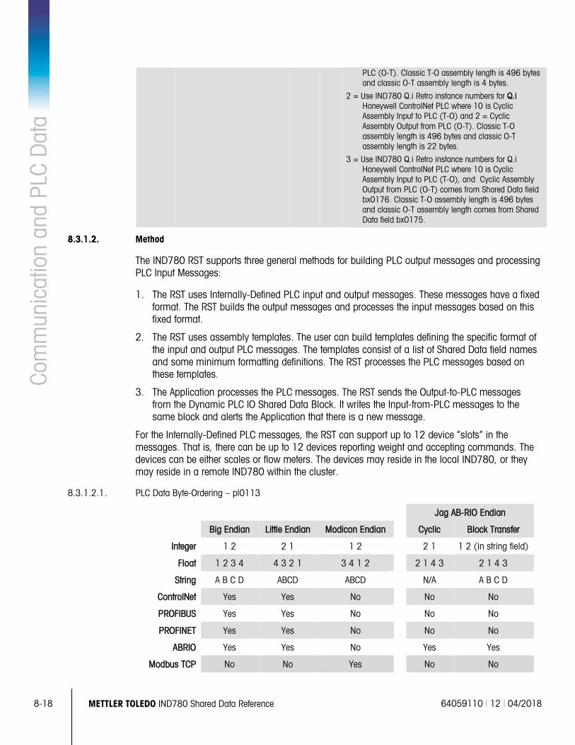
8-18 METTLER TOLEDO IND780 Shared Data Reference 64059110 | 12 | 04/2018
Com
mun
icat
ion
and
PLC
Dat
a PLC (O-T). Classic T-O assembly length is 496 bytes and classic O-T assembly length is 4 bytes.
2 = Use IND780 Q.i Retro instance numbers for Q.i Honeywell ControlNet PLC where 10 is Cyclic Assembly Input to PLC (T-O) and 2 = Cyclic Assembly Output from PLC (O-T). Classic T-O assembly length is 496 bytes and classic O-T assembly length is 22 bytes.
3 = Use IND780 Q.i Retro instance numbers for Q.i Honeywell ControlNet PLC where 10 is Cyclic Assembly Input to PLC (T-O), and Cyclic Assembly Output from PLC (O-T) comes from Shared Data field bx0176. Classic T-O assembly length is 496 bytes and classic O-T assembly length comes from Shared Data field bx0175.
8.3.1.2. Method
The IND780 RST supports three general methods for building PLC output messages and processing PLC Input Messages:
1. The RST uses Internally-Defined PLC input and output messages. These messages have a fixed format. The RST builds the output messages and processes the input messages based on this fixed format.
2. The RST uses assembly templates. The user can build templates defining the specific format of the input and output PLC messages. The templates consist of a list of Shared Data field names and some minimum formatting definitions. The RST processes the PLC messages based on these templates.
3. The Application processes the PLC messages. The RST sends the Output-to-PLC messages from the Dynamic PLC IO Shared Data Block. It writes the Input-from-PLC messages to the same block and alerts the Application that there is a new message.
For the Internally-Defined PLC messages, the RST can support up to 12 device “slots” in the messages. That is, there can be up to 12 devices reporting weight and accepting commands. The devices can be either scales or flow meters. The devices may reside in the local IND780, or they may reside in a remote IND780 within the cluster.
8.3.1.2.1. PLC Data Byte-Ordering – pl0113
Jag AB-RIO Endian
Big Endian Little Endian Modicon Endian Cyclic Block Transfer
Integer 1 2 2 1 1 2 2 1 1 2 (in string field)
Float 1 2 3 4 4 3 2 1 3 4 1 2 2 1 4 3 2 1 4 3
String A B C D ABCD ABCD N/A A B C D
ControlNet Yes Yes No No No
PROFIBUS Yes Yes No No No
PROFINET Yes Yes No No No
ABRIO Yes Yes No Yes Yes
Modbus TCP No No Yes No No
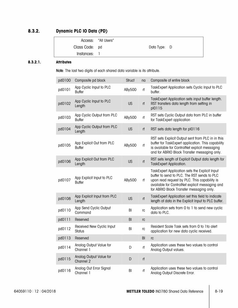
64059110 | 12 | 04/2018 METTLER TOLEDO IND780 Shared Data Reference 8-19
8.3.2. Dynamic PLC IO Data (PD)
Access: “All Users”
Class Code: pd Data Type: D
Instances: 1
8.3.2.1. Attributes
Note: The last two digits of each shared data variable is its attribute.
pd0100 Composite pd block Struct na Composite of entire block
pd0101 App Cyclic Input to PLC Buffer ABy500 rt
TaskExpert Application sets Cyclic Input to PLC buffer.
pd0102 App Cyclic Input to PLC Length US rt
TaskExpert Application sets input buffer length. RST transfers data length from setting in pl0115
pd0103 App Cyclic Output from PLC Buffer
ABy500 rt RST sets Cyclic Output data from PLC in buffer for TaskExpert application
pd0104 App Cyclic Output from PLC Length
US rt RST sets data length for pl0116
pd0105 App Explicit Out from PLC Buffer
ABy500 rt
RST sets Explicit Output sent from PLC in in this buffer for TaskExpert application. This capability is available for ControlNet explicit messaging and for ABRIO Block Transfer messaging only.
pd0106 App Explicit Out from PLC Length
US rt RST sets length of Explicit Output data length for TaskExpert Application.
pd0107 App Explicit Input to PLC Buffer
ABy500 rt
TaskExpert Application sets the Explicit Input buffer to send to PLC. The RST sends to PLC upon read request by PLC. This capability is available for ControlNet explicit messaging and for ABRIO Block Transfer messaging only.
pd0108 App Explicit Input from PLC Length US rt
TaskExpert Application set this field to indicate length of data in the Explicit Input to PLC buffer.
pd0110 App Send Cyclic Output Command
Bl rc Application sets from 0 to 1 to send new cyclic data to PLC.
pd0111 Reserved Bl rc
pd0112 Received New Cyclic Input Status
Bl rc Resident Scale Task sets from 0 to 1to alert application for new data cyclic received.
pd0113 Reserved Bl rc
pd0114 Analog Output Value for Channel 1 D rt
Application uses these two values to control Analog Output values.
pd0115 Analog Output Value for Channel 2
D rt
pd0116 Analog Out Error Signal Channel 1 Bl rt
Application uses these two values to control Analog Output Discrete Error.
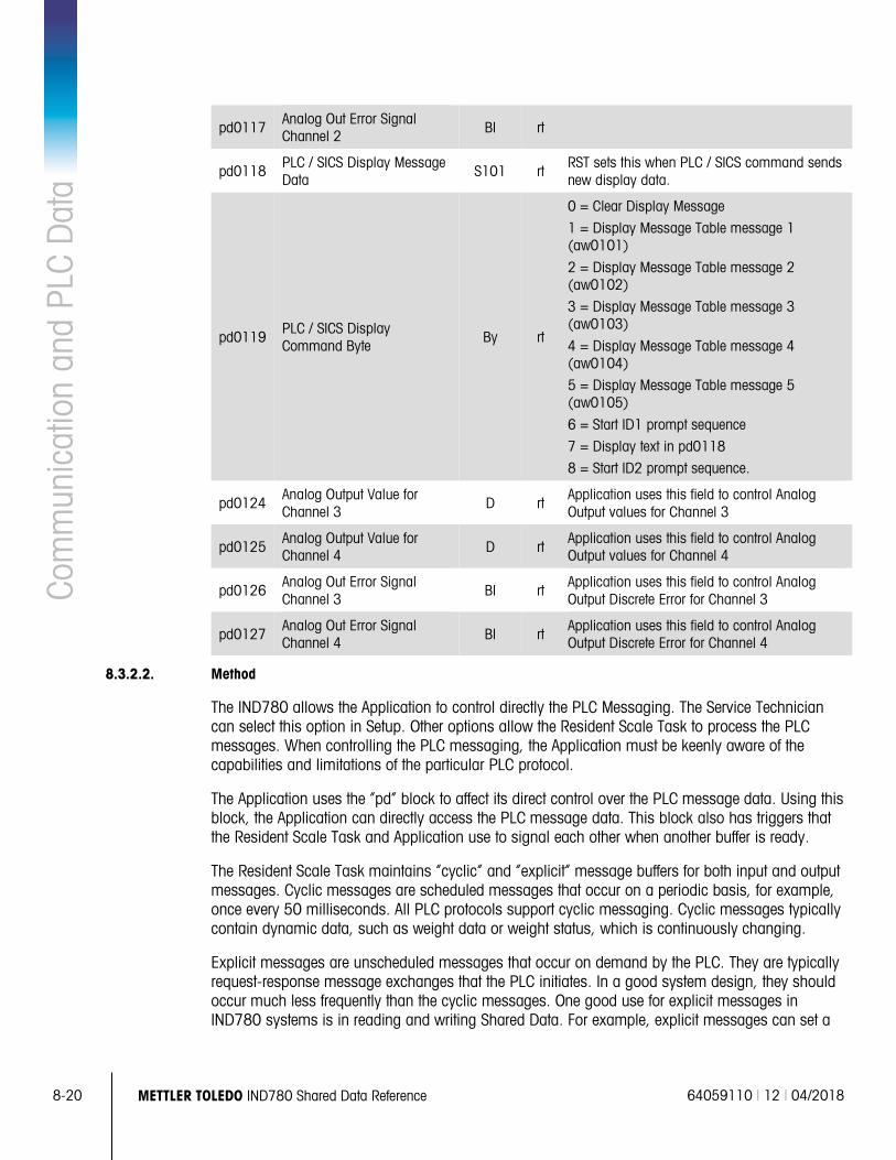
8-20 METTLER TOLEDO IND780 Shared Data Reference 64059110 | 12 | 04/2018
Com
mun
icat
ion
and
PLC
Dat
a
pd0117 Analog Out Error Signal Channel 2 Bl rt
pd0118 PLC / SICS Display Message Data
S101 rt RST sets this when PLC / SICS command sends new display data.
pd0119 PLC / SICS Display Command Byte
By rt
0 = Clear Display Message
1 = Display Message Table message 1 (aw0101)
2 = Display Message Table message 2 (aw0102)
3 = Display Message Table message 3 (aw0103)
4 = Display Message Table message 4 (aw0104)
5 = Display Message Table message 5 (aw0105)
6 = Start ID1 prompt sequence
7 = Display text in pd0118
8 = Start ID2 prompt sequence.
pd0124 Analog Output Value for Channel 3
D rt Application uses this field to control Analog Output values for Channel 3
pd0125 Analog Output Value for Channel 4 D rt
Application uses this field to control Analog Output values for Channel 4
pd0126 Analog Out Error Signal Channel 3
Bl rt Application uses this field to control Analog Output Discrete Error for Channel 3
pd0127 Analog Out Error Signal Channel 4 Bl rt
Application uses this field to control Analog Output Discrete Error for Channel 4
8.3.2.2. Method
The IND780 allows the Application to control directly the PLC Messaging. The Service Technician can select this option in Setup. Other options allow the Resident Scale Task to process the PLC messages. When controlling the PLC messaging, the Application must be keenly aware of the capabilities and limitations of the particular PLC protocol.
The Application uses the “pd” block to affect its direct control over the PLC message data. Using this block, the Application can directly access the PLC message data. This block also has triggers that the Resident Scale Task and Application use to signal each other when another buffer is ready.
The Resident Scale Task maintains “cyclic” and “explicit” message buffers for both input and output messages. Cyclic messages are scheduled messages that occur on a periodic basis, for example, once every 50 milliseconds. All PLC protocols support cyclic messaging. Cyclic messages typically contain dynamic data, such as weight data or weight status, which is continuously changing.
Explicit messages are unscheduled messages that occur on demand by the PLC. They are typically request-response message exchanges that the PLC initiates. In a good system design, they should occur much less frequently than the cyclic messages. One good use for explicit messages in IND780 systems is in reading and writing Shared Data. For example, explicit messages can set a
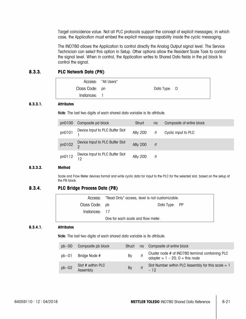
64059110 | 12 | 04/2018 METTLER TOLEDO IND780 Shared Data Reference 8-21
Target coincidence value. Not all PLC protocols support the concept of explicit messages; in which case, the Application must embed the explicit message capability inside the cyclic messaging.
The IND780 allows the Application to control directly the Analog Output signal level. The Service Technician can select this option in Setup. Other options allow the Resident Scale Task to control the signal level. When in control, the Application writes to Shared Data fields in the pd block to control the signal.
8.3.3. PLC Network Data (PN)
Access: “All Users”
Class Code: pn Data Type: D
Instances: 1
8.3.3.1. Attributes
Note: The last two digits of each shared data variable is its attribute.
pn0100 Composite pd block Struct na Composite of entire block
pn0101 Device Input to PLC Buffer Slot 1
ABy 200 rt Cyclic input to PLC
pn0102 Device Input to PLC Buffer Slot 2
ABy 200 rt
pn0112 Device Input to PLC Buffer Slot 12
ABy 200 rt
8.3.3.2. Method
Scale and Flow Meter devices format and write cyclic data for input to the PLC for the selected slot, based on the setup of the PB block.
8.3.4. PLC Bridge Process Data (PB)
Access: “Read Only” access, level is not customizable.
Class Code: pb Data Type: PP
Instances: 17
One for each scale and flow meter.
8.3.4.1. Attributes
Note: The last two digits of each shared data variable is its attribute.
pb--00 Composite pb block Struct na Composite of entire block
pb--01 Bridge Node # By rt Cluster node # of IND780 terminal containing PLC adapter = 1 – 20; 0 = this node
pb--02 Slot # within PLC Assembly
By rt Slot Number within PLC Assembly for this scale = 1 – 12
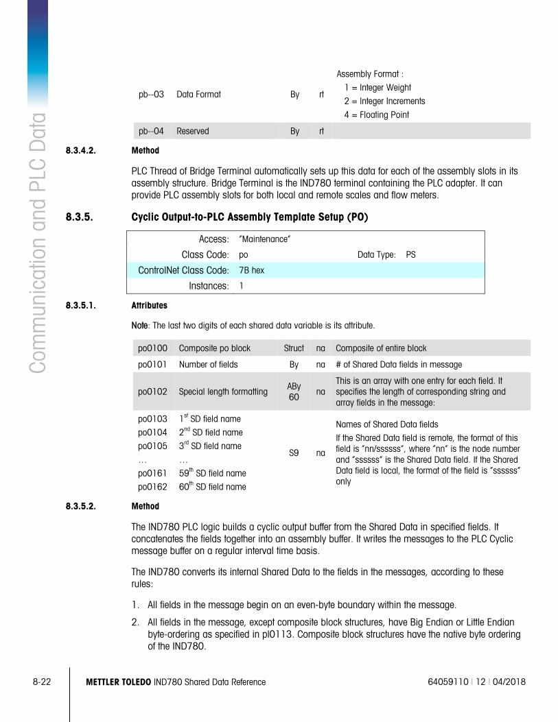
8-22 METTLER TOLEDO IND780 Shared Data Reference 64059110 | 12 | 04/2018
Com
mun
icat
ion
and
PLC
Dat
a
pb--03 Data Format By rt
Assembly Format :
1 = Integer Weight
2 = Integer Increments
4 = Floating Point
pb--04 Reserved By rt
8.3.4.2. Method
PLC Thread of Bridge Terminal automatically sets up this data for each of the assembly slots in its assembly structure. Bridge Terminal is the IND780 terminal containing the PLC adapter. It can provide PLC assembly slots for both local and remote scales and flow meters.
8.3.5. Cyclic Output-to-PLC Assembly Template Setup (PO)
Access: “Maintenance”
Class Code: po Data Type: PS
ControlNet Class Code: 7B hex
Instances: 1
8.3.5.1. Attributes
Note: The last two digits of each shared data variable is its attribute.
po0100 Composite po block Struct na Composite of entire block
po0101 Number of fields By na # of Shared Data fields in message
po0102 Special length formatting ABy 60
na This is an array with one entry for each field. It specifies the length of corresponding string and array fields in the message:
po0103
po0104
po0105
…
po0161
po0162
1st SD field name
2nd SD field name
3rd SD field name
…
59th SD field name
60th SD field name
S9 na
Names of Shared Data fields
If the Shared Data field is remote, the format of this field is “nn/ssssss”, where “nn” is the node number and “ssssss” is the Shared Data field. If the Shared Data field is local, the format of the field is “ssssss” only
8.3.5.2. Method
The IND780 PLC logic builds a cyclic output buffer from the Shared Data in specified fields. It concatenates the fields together into an assembly buffer. It writes the messages to the PLC Cyclic message buffer on a regular interval time basis.
The IND780 converts its internal Shared Data to the fields in the messages, according to these rules:
1. All fields in the message begin on an even-byte boundary within the message.
2. All fields in the message, except composite block structures, have Big Endian or Little Endian byte-ordering as specified in pl0113. Composite block structures have the native byte ordering of the IND780.
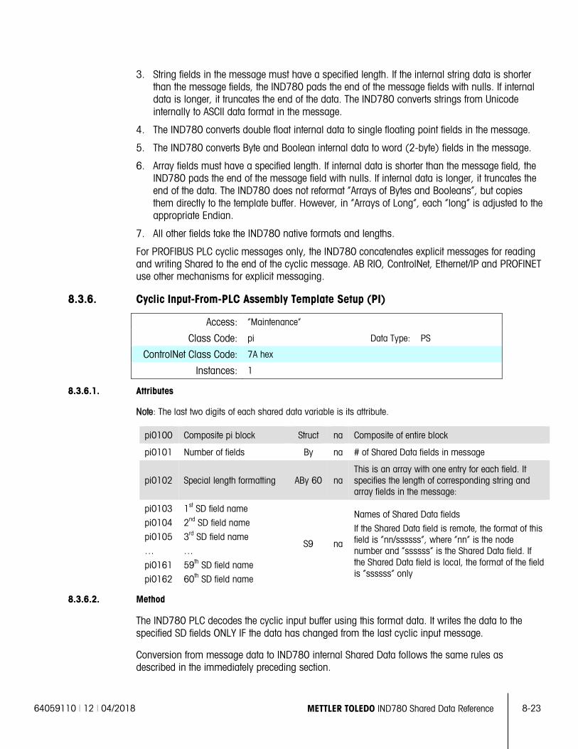
64059110 | 12 | 04/2018 METTLER TOLEDO IND780 Shared Data Reference 8-23
3. String fields in the message must have a specified length. If the internal string data is shorter than the message fields, the IND780 pads the end of the message fields with nulls. If internal data is longer, it truncates the end of the data. The IND780 converts strings from Unicode internally to ASCII data format in the message.
4. The IND780 converts double float internal data to single floating point fields in the message.
5. The IND780 converts Byte and Boolean internal data to word (2-byte) fields in the message.
6. Array fields must have a specified length. If internal data is shorter than the message field, the IND780 pads the end of the message field with nulls. If internal data is longer, it truncates the end of the data. The IND780 does not reformat “Arrays of Bytes and Booleans”, but copies them directly to the template buffer. However, in “Arrays of Long”, each “long” is adjusted to the appropriate Endian.
7. All other fields take the IND780 native formats and lengths.
For PROFIBUS PLC cyclic messages only, the IND780 concatenates explicit messages for reading and writing Shared to the end of the cyclic message. AB RIO, ControlNet, Ethernet/IP and PROFINET use other mechanisms for explicit messaging.
8.3.6. Cyclic Input-From-PLC Assembly Template Setup (PI)
Access: “Maintenance”
Class Code: pi Data Type: PS
ControlNet Class Code: 7A hex
Instances: 1
8.3.6.1. Attributes
Note: The last two digits of each shared data variable is its attribute.
pi0100 Composite pi block Struct na Composite of entire block
pi0101 Number of fields By na # of Shared Data fields in message
pi0102 Special length formatting ABy 60 na This is an array with one entry for each field. It specifies the length of corresponding string and array fields in the message:
pi0103
pi0104
pi0105
…
pi0161
pi0162
1st SD field name
2nd SD field name
3rd SD field name
…
59th SD field name
60th SD field name
S9 na
Names of Shared Data fields
If the Shared Data field is remote, the format of this field is “nn/ssssss”, where “nn” is the node number and “ssssss” is the Shared Data field. If the Shared Data field is local, the format of the field is “ssssss” only
8.3.6.2. Method
The IND780 PLC decodes the cyclic input buffer using this format data. It writes the data to the specified SD fields ONLY IF the data has changed from the last cyclic input message.
Conversion from message data to IND780 internal Shared Data follows the same rules as described in the immediately preceding section.
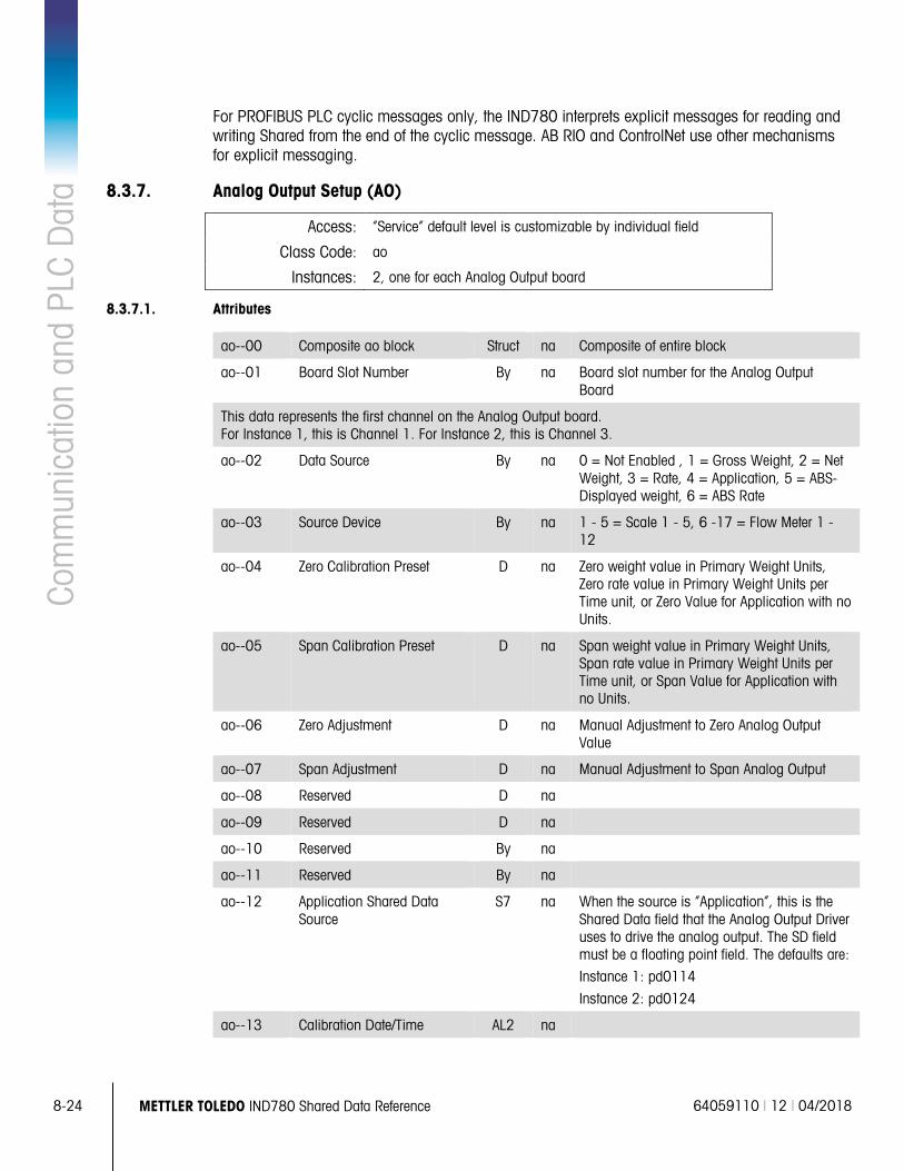
8-24 METTLER TOLEDO IND780 Shared Data Reference 64059110 | 12 | 04/2018
Com
mun
icat
ion
and
PLC
Dat
a For PROFIBUS PLC cyclic messages only, the IND780 interprets explicit messages for reading and writing Shared from the end of the cyclic message. AB RIO and ControlNet use other mechanisms for explicit messaging.
8.3.7. Analog Output Setup (AO)
Access: “Service” default level is customizable by individual field
Class Code: ao
Instances: 2, one for each Analog Output board
8.3.7.1. Attributes
ao--00 Composite ao block Struct na Composite of entire block
ao--01 Board Slot Number By na Board slot number for the Analog Output Board
This data represents the first channel on the Analog Output board. For Instance 1, this is Channel 1. For Instance 2, this is Channel 3.
ao--02 Data Source By na 0 = Not Enabled , 1 = Gross Weight, 2 = Net Weight, 3 = Rate, 4 = Application, 5 = ABS-Displayed weight, 6 = ABS Rate
ao--03 Source Device By na 1 - 5 = Scale 1 - 5, 6 -17 = Flow Meter 1 - 12
ao--04 Zero Calibration Preset D na Zero weight value in Primary Weight Units, Zero rate value in Primary Weight Units per Time unit, or Zero Value for Application with no Units.
ao--05 Span Calibration Preset D na Span weight value in Primary Weight Units, Span rate value in Primary Weight Units per Time unit, or Span Value for Application with no Units.
ao--06 Zero Adjustment D na Manual Adjustment to Zero Analog Output Value
ao--07 Span Adjustment D na Manual Adjustment to Span Analog Output
ao--08 Reserved D na
ao--09 Reserved D na
ao--10 Reserved By na
ao--11 Reserved By na
ao--12 Application Shared Data Source
S7 na When the source is “Application”, this is the Shared Data field that the Analog Output Driver uses to drive the analog output. The SD field must be a floating point field. The defaults are:
Instance 1: pd0114
Instance 2: pd0124
ao--13 Calibration Date/Time AL2 na
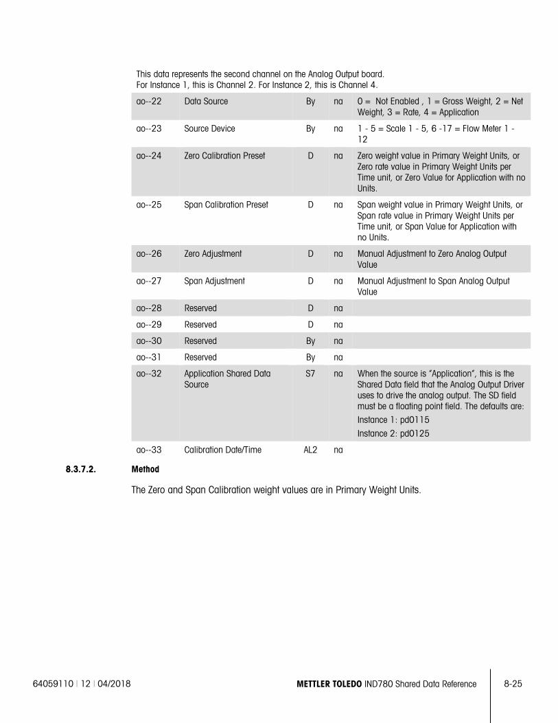
64059110 | 12 | 04/2018 METTLER TOLEDO IND780 Shared Data Reference 8-25
This data represents the second channel on the Analog Output board. For Instance 1, this is Channel 2. For Instance 2, this is Channel 4.
ao--22 Data Source By na 0 = Not Enabled , 1 = Gross Weight, 2 = Net Weight, 3 = Rate, 4 = Application
ao--23 Source Device By na 1 - 5 = Scale 1 - 5, 6 -17 = Flow Meter 1 - 12
ao--24 Zero Calibration Preset D na Zero weight value in Primary Weight Units, or Zero rate value in Primary Weight Units per Time unit, or Zero Value for Application with no Units.
ao--25 Span Calibration Preset D na Span weight value in Primary Weight Units, or Span rate value in Primary Weight Units per Time unit, or Span Value for Application with no Units.
ao--26 Zero Adjustment D na Manual Adjustment to Zero Analog Output Value
ao--27 Span Adjustment D na Manual Adjustment to Span Analog Output Value
ao--28 Reserved D na
ao--29 Reserved D na
ao--30 Reserved By na
ao--31 Reserved By na
ao--32 Application Shared Data Source
S7 na When the source is “Application”, this is the Shared Data field that the Analog Output Driver uses to drive the analog output. The SD field must be a floating point field. The defaults are:
Instance 1: pd0115
Instance 2: pd0125
ao--33 Calibration Date/Time AL2 na
8.3.7.2. Method
The Zero and Span Calibration weight values are in Primary Weight Units.
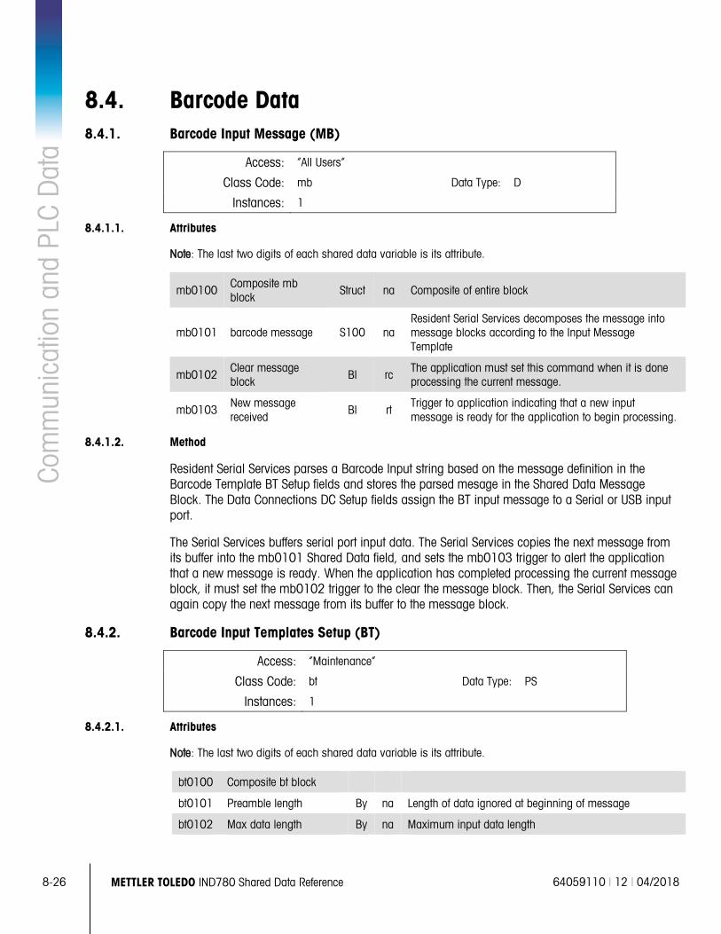
8-26 METTLER TOLEDO IND780 Shared Data Reference 64059110 | 12 | 04/2018
Com
mun
icat
ion
and
PLC
Dat
a
8.4. Barcode Data 8.4.1. Barcode Input Message (MB)
Access: “All Users”
Class Code: mb Data Type: D
Instances: 1
8.4.1.1. Attributes
Note: The last two digits of each shared data variable is its attribute.
mb0100 Composite mb block
Struct na Composite of entire block
mb0101 barcode message S100 na Resident Serial Services decomposes the message into message blocks according to the Input Message Template
mb0102 Clear message block Bl rc
The application must set this command when it is done processing the current message.
mb0103 New message received
Bl rt Trigger to application indicating that a new input message is ready for the application to begin processing.
8.4.1.2. Method
Resident Serial Services parses a Barcode Input string based on the message definition in the Barcode Template BT Setup fields and stores the parsed mesage in the Shared Data Message Block. The Data Connections DC Setup fields assign the BT input message to a Serial or USB input port.
The Serial Services buffers serial port input data. The Serial Services copies the next message from its buffer into the mb0101 Shared Data field, and sets the mb0103 trigger to alert the application that a new message is ready. When the application has completed processing the current message block, it must set the mb0102 trigger to the clear the message block. Then, the Serial Services can again copy the next message from its buffer to the message block.
8.4.2. Barcode Input Templates Setup (BT)
Access: “Maintenance”
Class Code: bt Data Type: PS
Instances: 1
8.4.2.1. Attributes
Note: The last two digits of each shared data variable is its attribute.
bt0100 Composite bt block
bt0101 Preamble length By na Length of data ignored at beginning of message
bt0102 Max data length By na Maximum input data length
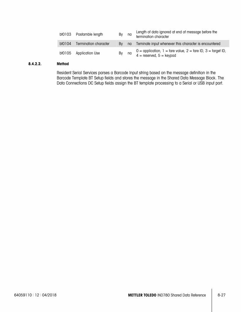
64059110 | 12 | 04/2018 METTLER TOLEDO IND780 Shared Data Reference 8-27
bt0103 Postamble length By na Length of data ignored at end of message before the termination character
bt0104 Termination character By na Teminate input whenever this character is encountered
bt0105 Application Use By na 0 = application, 1 = tare value, 2 = tare ID, 3 = target ID, 4 = reserved, 5 = keypad
8.4.2.2. Method
Resident Serial Services parses a Barcode Input string based on the message definition in the Barcode Template BT Setup fields and stores the message in the Shared Data Message Block. The Data Connections DC Setup fields assign the BT template processing to a Serial or USB input port.
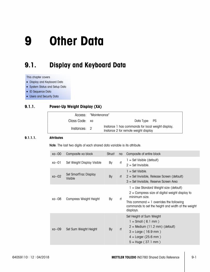
64059110 | 12 | 04/2018 METTLER TOLEDO IND780 Shared Data Reference 9-1
This chapter covers
• Display and Keyboard Data
• System Status and Setup Data
• ID Sequence Data
• Users and Security Data
9 Other Data
9.1. Display and Keyboard Data
9.1.1. Power-Up Weight Display (XA)
Access: “Maintenance”
Class Code: xa Data Type: PS
Instances: 2 Instance 1 has commands for local weight display, Instance 2 for remote weight display
9.1.1.1. Attributes
Note: The last two digits of each shared data variable is its attribute.
xa--00 Composite xa block Struct na Composite of entire block
xa--01 Set Weight Display Visible By rt 1 = Set Visible (default)
2 = Set Invisible.
xa--02 Set SmartTrac Display Visible By rt
1 = Set Visible.
2 = Set Invisible, Release Screen (default)
3 = Set Invisible, Reserve Screen Area
xa--08 Compress Weight Height By rt
1 = Use Standard Weight size (default)
2 = Compress size of digital weight display to minimum size.
This command = 1 overrides the following commands to set the height and width of the weight displays.
xa--09 Set Sum Weight Height By rt
Set Height of Sum Weight
1 = Small ( 6.1 mm )
2 = Medium (11.2 mm) (default)
3 = Large ( 16.9 mm )
4 = Larger (25.6 mm )
5 = Huge ( 37.1 mm )
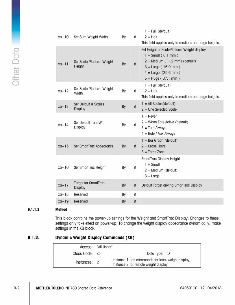
9-2 METTLER TOLEDO IND780 Shared Data Reference 64059110 | 12 | 04/2018
Oth
er D
ata
xa--10 Set Sum Weight Width By rt
1 = Full (default)
2 = Half
This field applies only to medium and large heights.
xa--11 Set Scale Platform Weight Height
By rt
Set Height of ScalePlatform Weight display
1 = Small ( 6.1 mm )
2 = Medium (11.2 mm) (default)
3 = Large ( 16.9 mm )
4 = Larger (25.6 mm )
5 = Huge ( 37.1 mm )
xa--12 Set Scale Platform Weight Width
By rt
1 = Full (default)
2 = Half
This field applies only to medium and large heights.
xa--13 Set Default # Scales Display
By rt 1 = All Scales(default)
2 = One Selected Scale
xa--14 Set Default Tare Wt. Display By rt
1 = Never
2 = When Tare Active (default)
3 = Tare Always
4 = Rate / Aux Always
xa--15 Set SmartTrac Appearance By rt
1 = Bar Graph (default)
2 = Cross Hairs
3 = Three Zone.
xa--16 Set SmartTrac Height By rt
SmartTrac Display Height
1 = Small
2 = Medium (default)
3 = Large
xa--17 Target for SmartTrac Display By rt Default Target driving SmartTrac Display
xa--18 Reserved By rt
xa--19 Reserved By rt
9.1.1.2. Method
This block contains the power-up settings for the Weight and SmartTrac Display. Changes to these settings only take effect on power-up. To change the weight display appearance dynamically, make settings in the XB block.
9.1.2. Dynamic Weight Display Commands (XB)
Access: “All Users”
Class Code: xb Data Type: D
Instances: 2 Instance 1 has commands for local weight display, Instance 2 for remote weight display
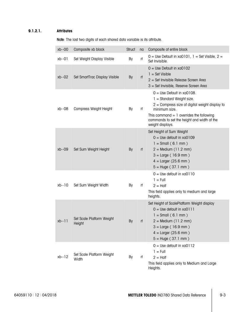
64059110 | 12 | 04/2018 METTLER TOLEDO IND780 Shared Data Reference 9-3
9.1.2.1. Attributes
Note: The last two digits of each shared data variable is its attribute.
xb--00 Composite xb block Struct na Composite of entire block
xb--01 Set Weight Display Visible By rt 0 = Use Default in xa0101, 1 = Set Visible, 2 = Set Invisible.
xb--02 Set SmartTrac Display Visible By rt
0 = Use Default in xa0102
1 = Set Visible
2 = Set Invisible Release Screen Area
3 = Set Invisible, Reserve Screen Area
xb--08 Compress Weight Height By rt
0 = Use Default in xa0108.
1 = Standard Weight size.
2 = Compress size of digital weight display to minimum size.
This command = 1 overrides the following commands to set the height and width of the weight displays.
xb--09 Set Sum Weight Height By rt
Set Height of Sum Weight
0 = Use default in xa0109
1 = Small ( 6.1 mm )
2 = Medium (11.2 mm)
3 = Large ( 16.9 mm )
4 = Larger (25.6 mm )
5 = Huge ( 37.1 mm )
xb--10 Set Sum Weight Width By rt
0 = Use default in xa0110
1 = Full
2 = Half
This field applies only to medium and large heights.
xb--11 Set Scale Platform Weight Height
By rt
Set Height of ScalePlatform Weight display
0 = Use default in xa0111
1 = Small ( 6.1 mm )
2 = Medium (11.2 mm)
3 = Large ( 16.9 mm )
4 = Larger (25.6 mm )
5 = Huge ( 37.1 mm )
xb--12 Set Scale Platform Weight Width
By rt
0 = Use default in xa0112
1 = Full
2 = Half
This field applies only to Medium and Large Heights.
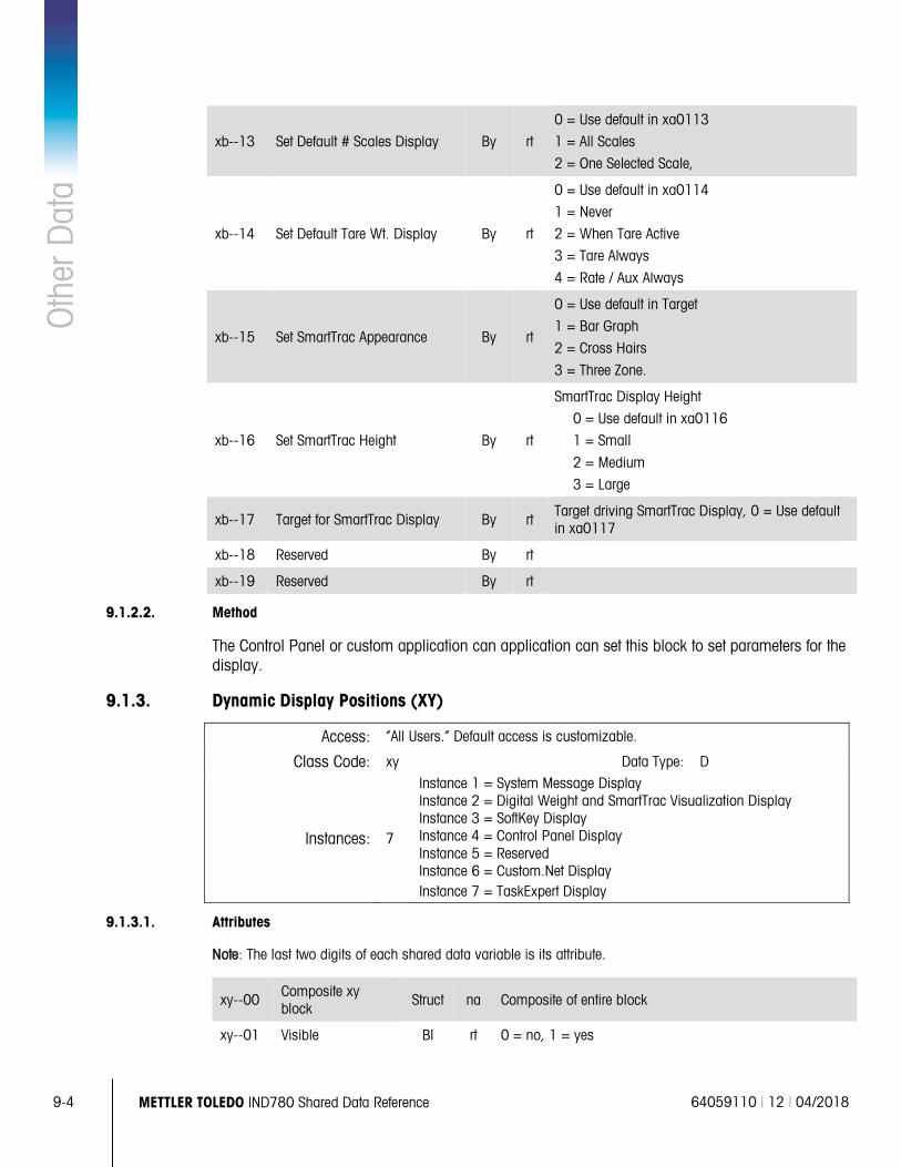
9-4 METTLER TOLEDO IND780 Shared Data Reference 64059110 | 12 | 04/2018
Oth
er D
ata
xb--13 Set Default # Scales Display By rt
0 = Use default in xa0113
1 = All Scales
2 = One Selected Scale,
xb--14 Set Default Tare Wt. Display By rt
0 = Use default in xa0114
1 = Never
2 = When Tare Active
3 = Tare Always
4 = Rate / Aux Always
xb--15 Set SmartTrac Appearance By rt
0 = Use default in Target
1 = Bar Graph
2 = Cross Hairs
3 = Three Zone.
xb--16 Set SmartTrac Height By rt
SmartTrac Display Height
0 = Use default in xa0116
1 = Small
2 = Medium
3 = Large
xb--17 Target for SmartTrac Display By rt Target driving SmartTrac Display, 0 = Use default in xa0117
xb--18 Reserved By rt
xb--19 Reserved By rt
9.1.2.2. Method
The Control Panel or custom application can application can set this block to set parameters for the display.
9.1.3. Dynamic Display Positions (XY)
Access: “All Users.” Default access is customizable.
Class Code: xy Data Type: D
Instances: 7
Instance 1 = System Message Display Instance 2 = Digital Weight and SmartTrac Visualization Display Instance 3 = SoftKey Display Instance 4 = Control Panel Display Instance 5 = Reserved Instance 6 = Custom.Net Display Instance 7 = TaskExpert Display
9.1.3.1. Attributes
Note: The last two digits of each shared data variable is its attribute.
xy--00 Composite xy block
Struct na Composite of entire block
xy--01 Visible Bl rt 0 = no, 1 = yes
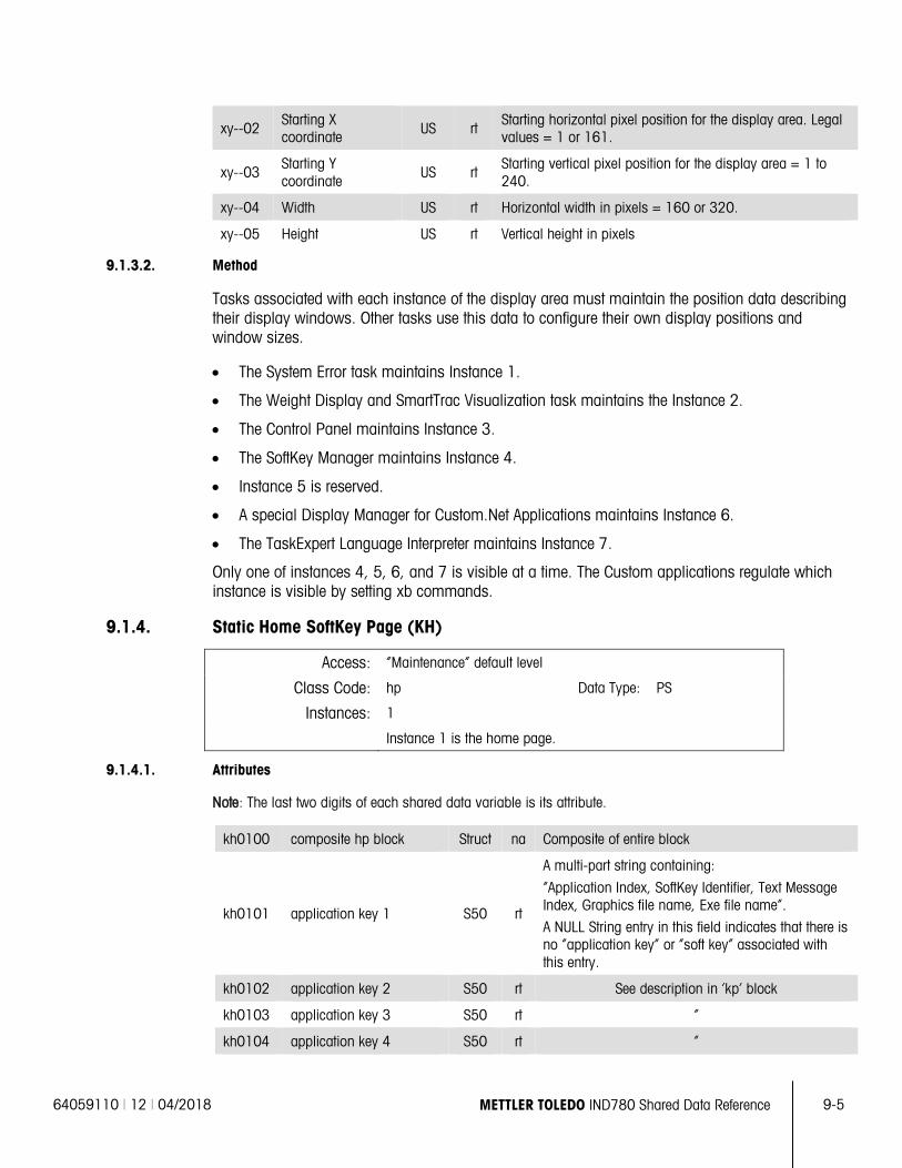
64059110 | 12 | 04/2018 METTLER TOLEDO IND780 Shared Data Reference 9-5
xy--02 Starting X coordinate US rt
Starting horizontal pixel position for the display area. Legal values = 1 or 161.
xy--03 Starting Y coordinate
US rt Starting vertical pixel position for the display area = 1 to 240.
xy--04 Width US rt Horizontal width in pixels = 160 or 320.
xy--05 Height US rt Vertical height in pixels
9.1.3.2. Method
Tasks associated with each instance of the display area must maintain the position data describing their display windows. Other tasks use this data to configure their own display positions and window sizes.
• The System Error task maintains Instance 1.
• The Weight Display and SmartTrac Visualization task maintains the Instance 2.
• The Control Panel maintains Instance 3.
• The SoftKey Manager maintains Instance 4.
• Instance 5 is reserved.
• A special Display Manager for Custom.Net Applications maintains Instance 6.
• The TaskExpert Language Interpreter maintains Instance 7.
Only one of instances 4, 5, 6, and 7 is visible at a time. The Custom applications regulate which instance is visible by setting xb commands.
9.1.4. Static Home SoftKey Page (KH)
Access: “Maintenance” default level
Class Code: hp Data Type: PS
Instances: 1
Instance 1 is the home page.
9.1.4.1. Attributes
Note: The last two digits of each shared data variable is its attribute.
kh0100 composite hp block Struct na Composite of entire block
kh0101 application key 1 S50 rt
A multi-part string containing:
“Application Index, SoftKey Identifier, Text Message Index, Graphics file name, Exe file name”.
A NULL String entry in this field indicates that there is no “application key” or “soft key” associated with this entry.
kh0102 application key 2 S50 rt See description in ‘kp’ block
kh0103 application key 3 S50 rt “
kh0104 application key 4 S50 rt “
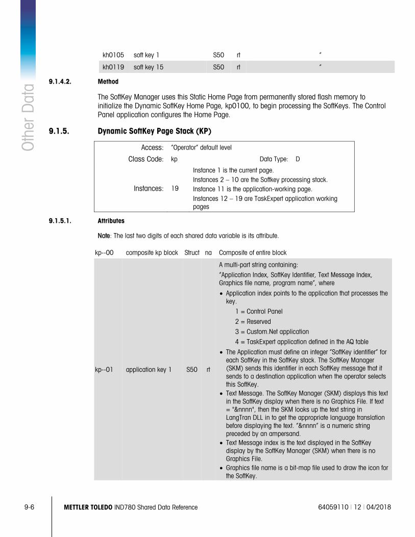
9-6 METTLER TOLEDO IND780 Shared Data Reference 64059110 | 12 | 04/2018
Oth
er D
ata
kh0105 soft key 1 S50 rt “
kh0119 soft key 15 S50 rt “
9.1.4.2. Method
The SoftKey Manager uses this Static Home Page from permanently stored flash memory to initialize the Dynamic SoftKey Home Page, kp0100, to begin processing the SoftKeys. The Control Panel application configures the Home Page.
9.1.5. Dynamic SoftKey Page Stack (KP)
Access: “Operator” default level
Class Code: kp Data Type: D
Instances: 19
Instance 1 is the current page. Instances 2 – 10 are the Softkey processing stack. Instance 11 is the application-working page. Instances 12 – 19 are TaskExpert application working pages
9.1.5.1. Attributes
Note: The last two digits of each shared data variable is its attribute.
kp--00 composite kp block Struct na Composite of entire block
kp--01 application key 1 S50 rt
A multi-part string containing:
“Application Index, SoftKey Identifier, Text Message Index, Graphics file name, program name”, where
• Application index points to the application that processes the key.
1 = Control Panel
2 = Reserved
3 = Custom.Net application
4 = TaskExpert application defined in the AQ table
• The Application must define an integer “SoftKey identifier” for each SoftKey in the SoftKey stack. The SoftKey Manager (SKM) sends this identifier in each SoftKey message that it sends to a destination application when the operator selects this SoftKey.
• Text Message. The SoftKey Manager (SKM) displays this text in the SoftKey display when there is no Graphics File. If text = "&nnnn", then the SKM looks up the text string in LangTran DLL in to get the appropriate language translation before displaying the text. “&nnnn” is a numeric string preceded by an ampersand.
• Text Message index is the text displayed in the SoftKey display by the SoftKey Manager (SKM) when there is no Graphics File.
• Graphics file name is a bit-map file used to draw the icon for the SoftKey.
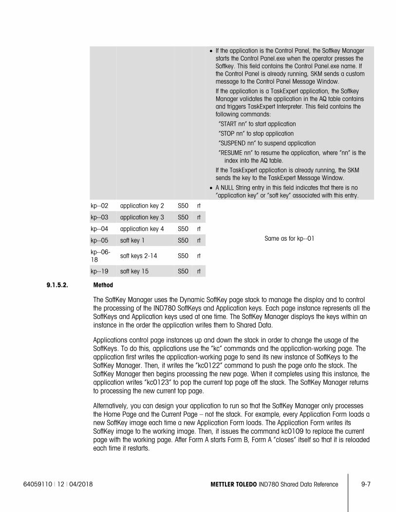
64059110 | 12 | 04/2018 METTLER TOLEDO IND780 Shared Data Reference 9-7
• If the application is the Control Panel, the Softkey Manager starts the Control Panel.exe when the operator presses the Softkey. This field contains the Control Panel.exe name. If the Control Panel is already running, SKM sends a custom message to the Control Panel Message Window.
If the application is a TaskExpert application, the Softkey Manager validates the application in the AQ table contains and triggers TaskExpert Interpreter. This field contains the following commands:
“START nn” to start application
“STOP nn” to stop application
“SUSPEND nn” to suspend application
“RESUME nn” to resume the application, where “nn” is the index into the AQ table.
If the TaskExpert application is already running, the SKM sends the key to the TaskExpert Message Window.
• A NULL String entry in this field indicates that there is no “application key” or “soft key” associated with this entry.
kp--02 application key 2 S50 rt
Same as for kp--01
kp--03 application key 3 S50 rt
kp--04 application key 4 S50 rt
kp--05 soft key 1 S50 rt
kp--06-18
soft keys 2-14 S50 rt
kp--19 soft key 15 S50 rt
9.1.5.2. Method
The SoftKey Manager uses the Dynamic SoftKey page stack to manage the display and to control the processing of the IND780 SoftKeys and Application keys. Each page instance represents all the SoftKeys and Application keys used at one time. The SoftKey Manager displays the keys within an instance in the order the application writes them to Shared Data.
Applications control page instances up and down the stack in order to change the usage of the SoftKeys. To do this, applications use the “kc” commands and the application-working page. The application first writes the application-working page to send its new instance of SoftKeys to the SoftKey Manager. Then, it writes the “kc0122” command to push the page onto the stack. The SoftKey Manager then begins processing the new page. When it completes using this instance, the application writes “kc0123” to pop the current top page off the stack. The SoftKey Manager returns to processing the new current top page.
Alternatively, you can design your application to run so that the SoftKey Manager only processes the Home Page and the Current Page – not the stack. For example, every Application Form loads a new SoftKey image each time a new Application Form loads. The Application Form writes its SoftKey image to the working image. Then, it issues the command kc0109 to replace the current page with the working page. After Form A starts Form B, Form A “closes” itself so that it is reloaded each time it restarts.
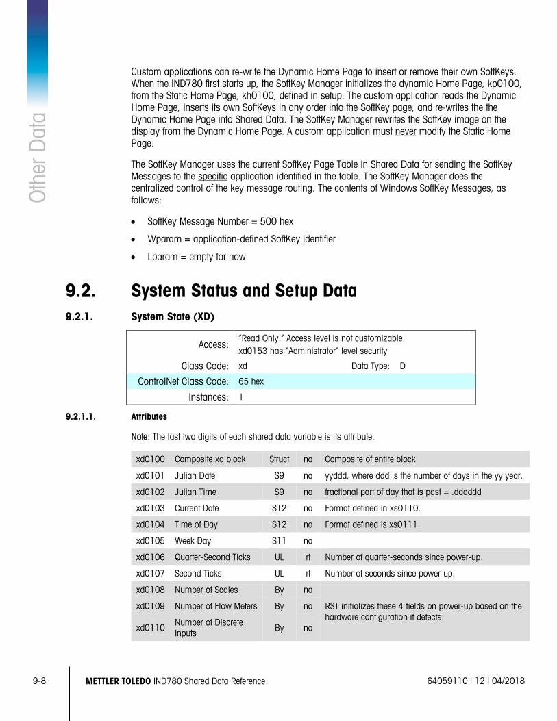
9-8 METTLER TOLEDO IND780 Shared Data Reference 64059110 | 12 | 04/2018
Oth
er D
ata
Custom applications can re-write the Dynamic Home Page to insert or remove their own SoftKeys. When the IND780 first starts up, the SoftKey Manager initializes the dynamic Home Page, kp0100, from the Static Home Page, kh0100, defined in setup. The custom application reads the Dynamic Home Page, inserts its own SoftKeys in any order into the SoftKey page, and re-writes the the Dynamic Home Page into Shared Data. The SoftKey Manager rewrites the SoftKey image on the display from the Dynamic Home Page. A custom application must never modify the Static Home Page.
The SoftKey Manager uses the current SoftKey Page Table in Shared Data for sending the SoftKey Messages to the specific application identified in the table. The SoftKey Manager does the centralized control of the key message routing. The contents of Windows SoftKey Messages, as follows:
• SoftKey Message Number = 500 hex
• Wparam = application-defined SoftKey identifier
• Lparam = empty for now
9.2. System Status and Setup Data 9.2.1. System State (XD)
Access: “Read Only.” Access level is not customizable. xd0153 has “Administrator” level security
Class Code: xd Data Type: D
ControlNet Class Code: 65 hex
Instances: 1
9.2.1.1. Attributes
Note: The last two digits of each shared data variable is its attribute.
xd0100 Composite xd block Struct na Composite of entire block
xd0101 Julian Date S9 na yyddd, where ddd is the number of days in the yy year.
xd0102 Julian Time S9 na fractional part of day that is past = .dddddd
xd0103 Current Date S12 na Format defined in xs0110.
xd0104 Time of Day S12 na Format defined is xs0111.
xd0105 Week Day S11 na
xd0106 Quarter-Second Ticks UL rt Number of quarter-seconds since power-up.
xd0107 Second Ticks UL rt Number of seconds since power-up.
xd0108 Number of Scales By na
RST initializes these 4 fields on power-up based on the hardware configuration it detects.
xd0109 Number of Flow Meters By na
xd0110 Number of Discrete Inputs
By na
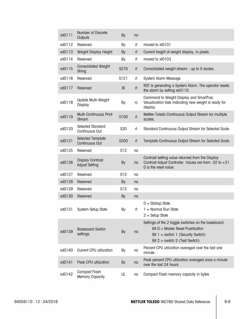
64059110 | 12 | 04/2018 METTLER TOLEDO IND780 Shared Data Reference 9-9
xd0111 Number of Discrete Outputs By na
xd0112 Reserved By rt moved to xt0101
xd0113 Weight Display Height By rt Current height of weight display, in pixels.
xd0114 Reserved By rt moved to xt0103
xd0115 Consolidated Weight String S270 rt Consolidated weight stream - up to 5 scales.
xd0116 Reserved S121 rt System Alarm Message
xd0117 Reserved Bl rt RST is generating a System Alarm. The operator resets the alarm by setting xk0110.
xd0118 Update Multi-Weight Display By rc
Command to Weight Display and SmartTrac Visualization task indicating new weight is ready for display.
xd0119 Multi-Continuous Print Stream S100 rt
Mettler-Toledo Continuous Output Stream for multiple scales.
xd0120 Selected Standard Continuous Out
S20 rt Standard Continuous Output Stream for Selected Scale.
xd0121 Selected Template Continuous Out S200 rt Template Continuous Output Stream for Selected Scale.
xd0125 Reserved S13 na
xd0126 Display Contrast Adjust Setting
By na Contrast setting value returned from the Display Contrast Adjust Controller. Values are from -32 to +31. 0 is the reset value.
xd0127 Reserved S13 na
xd0128 Reserved By na
xd0129 Reserved S13 na
xd0130 Reserved By na
xd0131 System Setup State By rt
0 = Startup State
1 = Normal Run State
2 = Setup State
xd0139 Baseboard Switch settings By na
Settings of the 2 toggle switches on the baseboard:
Bit 0 = Master Reset Pushbutton
Bit 1 = switch 1 (Security Switch)
Bit 2 = switch 2 (Test Switch)
xd0140 Current CPU utilization By na Percent CPU utilization averaged over the last one minute.
xd0141 Peak CPU utilization By na Peak percent CPU utilization averaged once a minute over the last 24 hours.
xd0142 Compact Flash Memory Capacity
UL na Compact Flash memory capacity in bytes
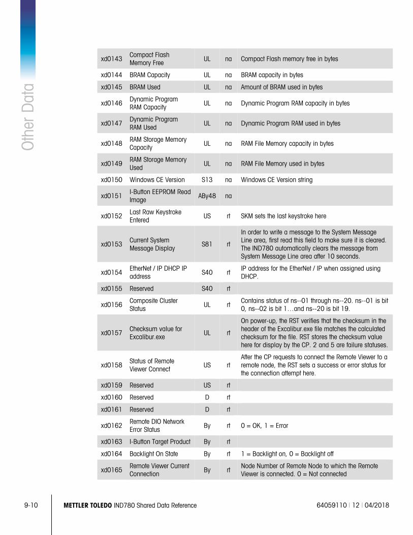
9-10 METTLER TOLEDO IND780 Shared Data Reference 64059110 | 12 | 04/2018
Oth
er D
ata
xd0143 Compact Flash Memory Free UL na Compact Flash memory free in bytes
xd0144 BRAM Capacity UL na BRAM capacity in bytes
xd0145 BRAM Used UL na Amount of BRAM used in bytes
xd0146 Dynamic Program RAM Capacity UL na Dynamic Program RAM capacity in bytes
xd0147 Dynamic Program RAM Used
UL na Dynamic Program RAM used in bytes
xd0148 RAM Storage Memory Capacity UL na RAM File Memory capacity in bytes
xd0149 RAM Storage Memory Used
UL na RAM File Memory used in bytes
xd0150 Windows CE Version S13 na Windows CE Version string
xd0151 I-Button EEPROM Read Image ABy48 na
xd0152 Last Raw Keystroke Entered
US rt SKM sets the last keystroke here
xd0153 Current System Message Display
S81 rt
In order to write a message to the System Message Line area, first read this field to make sure it is cleared. The IND780 automatically clears the message from System Message Line area after 10 seconds.
xd0154 EtherNet / IP DHCP IP address S40 rt
IP address for the EtherNet / IP when assigned using DHCP.
xd0155 Reserved S40 rt
xd0156 Composite Cluster Status UL rt
Contains status of ns--01 through ns--20. ns--01 is bit 0, ns--02 is bit 1…and ns--20 is bit 19.
xd0157 Checksum value for Excalibur.exe
UL rt
On power-up, the RST verifies that the checksum in the header of the Excalibur.exe file matches the calculated checksum for the file. RST stores the checksum value here for display by the CP. 2 and 5 are failure statuses.
xd0158 Status of Remote Viewer Connect US rt
After the CP requests to connect the Remote Viewer to a remote node, the RST sets a success or error status for the connection attempt here.
xd0159 Reserved US rt
xd0160 Reserved D rt
xd0161 Reserved D rt
xd0162 Remote DIO Network Error Status By rt 0 = OK, 1 = Error
xd0163 I-Button Target Product By rt
xd0164 Backlight On State By rt 1 = Backlight on, 0 = Backlight off
xd0165 Remote Viewer Current Connection By rt
Node Number of Remote Node to which the Remote Viewer is connected. 0 = Not connected
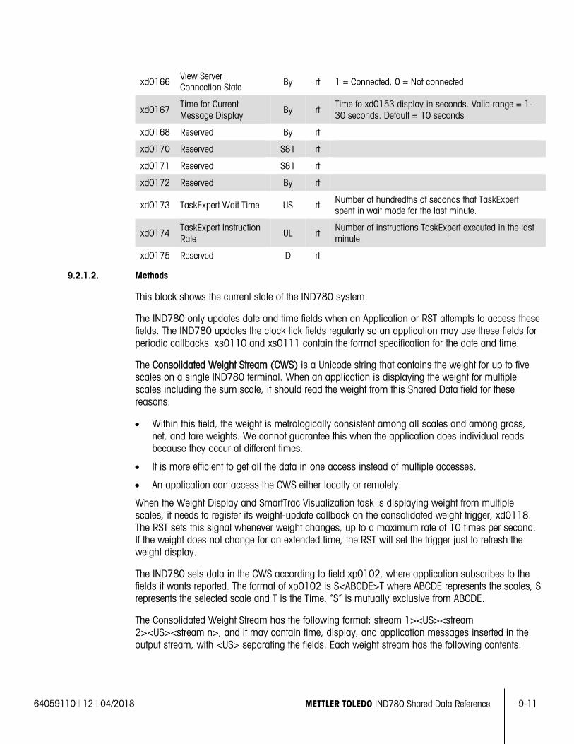
64059110 | 12 | 04/2018 METTLER TOLEDO IND780 Shared Data Reference 9-11
xd0166 View Server Connection State By rt 1 = Connected, 0 = Not connected
xd0167 Time for Current Message Display
By rt Time fo xd0153 display in seconds. Valid range = 1-30 seconds. Default = 10 seconds
xd0168 Reserved By rt
xd0170 Reserved S81 rt
xd0171 Reserved S81 rt
xd0172 Reserved By rt
xd0173 TaskExpert Wait Time US rt Number of hundredths of seconds that TaskExpert spent in wait mode for the last minute.
xd0174 TaskExpert Instruction Rate
UL rt Number of instructions TaskExpert executed in the last minute.
xd0175 Reserved D rt
9.2.1.2. Methods
This block shows the current state of the IND780 system.
The IND780 only updates date and time fields when an Application or RST attempts to access these fields. The IND780 updates the clock tick fields regularly so an application may use these fields for periodic callbacks. xs0110 and xs0111 contain the format specification for the date and time.
The Consolidated Weight Stream (CWS) is a Unicode string that contains the weight for up to five scales on a single IND780 terminal. When an application is displaying the weight for multiple scales including the sum scale, it should read the weight from this Shared Data field for these reasons:
• Within this field, the weight is metrologically consistent among all scales and among gross, net, and tare weights. We cannot guarantee this when the application does individual reads because they occur at different times.
• It is more efficient to get all the data in one access instead of multiple accesses.
• An application can access the CWS either locally or remotely.
When the Weight Display and SmartTrac Visualization task is displaying weight from multiple scales, it needs to register its weight-update callback on the consolidated weight trigger, xd0118. The RST sets this signal whenever weight changes, up to a maximum rate of 10 times per second. If the weight does not change for an extended time, the RST will set the trigger just to refresh the weight display.
The IND780 sets data in the CWS according to field xp0102, where application subscribes to the fields it wants reported. The format of xp0102 is S<ABCDE>T where ABCDE represents the scales, S represents the selected scale and T is the Time. “S” is mutually exclusive from ABCDE.
The Consolidated Weight Stream has the following format: stream 1><US><stream 2><US><stream n>, and it may contain time, display, and application messages inserted in the output stream, with <US> separating the fields. Each weight stream has the following contents:
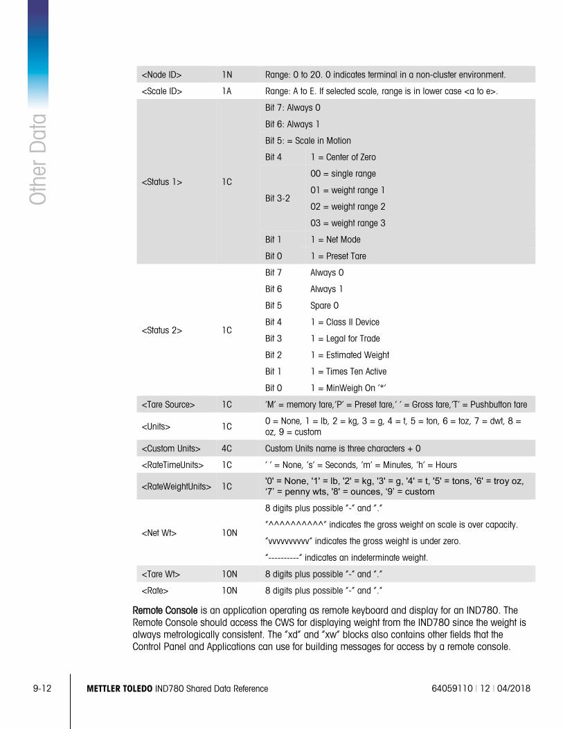
9-12 METTLER TOLEDO IND780 Shared Data Reference 64059110 | 12 | 04/2018
Oth
er D
ata
<Node ID> 1N Range: 0 to 20. 0 indicates terminal in a non-cluster environment.
<Scale ID> 1A Range: A to E. If selected scale, range is in lower case <a to e>.
<Status 1> 1C
Bit 7: Always 0
Bit 6: Always 1
Bit 5: = Scale in Motion
Bit 4 1 = Center of Zero
Bit 3-2
00 = single range
01 = weight range 1
02 = weight range 2
03 = weight range 3
Bit 1 1 = Net Mode
Bit 0 1 = Preset Tare
<Status 2> 1C
Bit 7 Always 0
Bit 6 Always 1
Bit 5 Spare 0
Bit 4 1 = Class II Device
Bit 3 1 = Legal for Trade
Bit 2 1 = Estimated Weight
Bit 1 1 = Times Ten Active
Bit 0 1 = MinWeigh On ‘*’
<Tare Source> 1C ‘M’ = memory tare,’P’ = Preset tare,’ ‘ = Gross tare,’T’ = Pushbutton tare
<Units> 1C 0 = None, 1 = lb, 2 = kg, 3 = g, 4 = t, 5 = ton, 6 = toz, 7 = dwt, 8 = oz, 9 = custom
<Custom Units> 4C Custom Units name is three characters + 0
<RateTimeUnits> 1C ‘ ‘ = None, ‘s’ = Seconds, ‘m’ = Minutes, ‘h’ = Hours
<RateWeightUnits> 1C '0' = None, '1' = lb, '2' = kg, '3' = g, '4' = t, '5' = tons, '6' = troy oz, ‘7’ = penny wts, '8' = ounces, ‘9’ = custom
<Net Wt> 10N
8 digits plus possible “-“ and “.”
“^^^^^^^^^^” indicates the gross weight on scale is over capacity.
“vvvvvvvvvv” indicates the gross weight is under zero.
“----------“ indicates an indeterminate weight.
<Tare Wt> 10N 8 digits plus possible “-“ and “.”
<Rate> 10N 8 digits plus possible “-“ and “.”
Remote Console is an application operating as remote keyboard and display for an IND780. The Remote Console should access the CWS for displaying weight from the IND780 since the weight is always metrologically consistent. The “xd” and “xw” blocks also contains other fields that the Control Panel and Applications can use for building messages for access by a remote console.
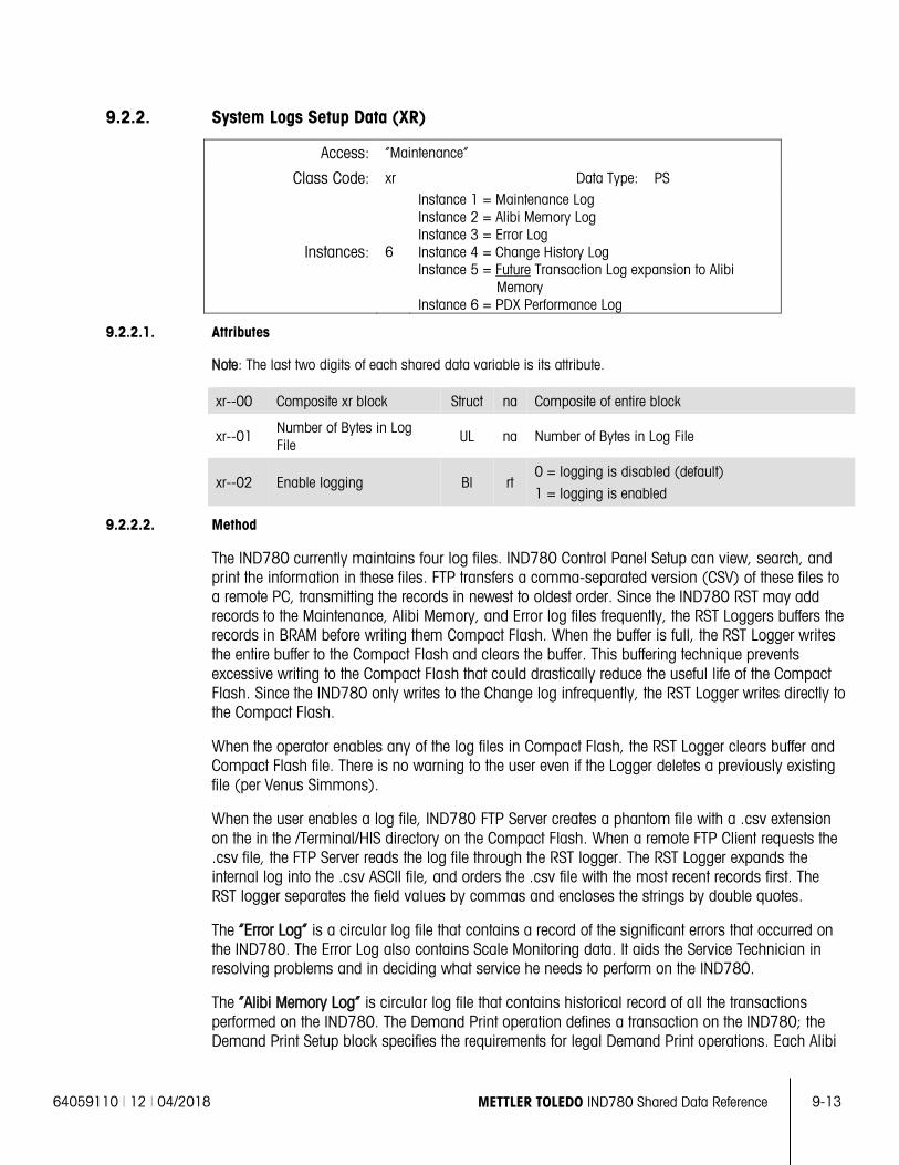
64059110 | 12 | 04/2018 METTLER TOLEDO IND780 Shared Data Reference 9-13
9.2.2. System Logs Setup Data (XR)
Access: “Maintenance”
Class Code: xr Data Type: PS
Instances: 6
Instance 1 = Maintenance Log Instance 2 = Alibi Memory Log Instance 3 = Error Log Instance 4 = Change History Log Instance 5 = Future Transaction Log expansion to Alibi
Memory Instance 6 = PDX Performance Log
9.2.2.1. Attributes
Note: The last two digits of each shared data variable is its attribute.
xr--00 Composite xr block Struct na Composite of entire block
xr--01 Number of Bytes in Log File
UL na Number of Bytes in Log File
xr--02 Enable logging Bl rt 0 = logging is disabled (default)
1 = logging is enabled
9.2.2.2. Method
The IND780 currently maintains four log files. IND780 Control Panel Setup can view, search, and print the information in these files. FTP transfers a comma-separated version (CSV) of these files to a remote PC, transmitting the records in newest to oldest order. Since the IND780 RST may add records to the Maintenance, Alibi Memory, and Error log files frequently, the RST Loggers buffers the records in BRAM before writing them Compact Flash. When the buffer is full, the RST Logger writes the entire buffer to the Compact Flash and clears the buffer. This buffering technique prevents excessive writing to the Compact Flash that could drastically reduce the useful life of the Compact Flash. Since the IND780 only writes to the Change log infrequently, the RST Logger writes directly to the Compact Flash.
When the operator enables any of the log files in Compact Flash, the RST Logger clears buffer and Compact Flash file. There is no warning to the user even if the Logger deletes a previously existing file (per Venus Simmons).
When the user enables a log file, IND780 FTP Server creates a phantom file with a .csv extension on the in the /Terminal/HIS directory on the Compact Flash. When a remote FTP Client requests the .csv file, the FTP Server reads the log file through the RST logger. The RST Logger expands the internal log into the .csv ASCII file, and orders the .csv file with the most recent records first. The RST logger separates the field values by commas and encloses the strings by double quotes.
The “Error Log” is a circular log file that contains a record of the significant errors that occurred on the IND780. The Error Log also contains Scale Monitoring data. It aids the Service Technician in resolving problems and in deciding what service he needs to perform on the IND780.
The “Alibi Memory Log” is circular log file that contains historical record of all the transactions performed on the IND780. The Demand Print operation defines a transaction on the IND780; the Demand Print Setup block specifies the requirements for legal Demand Print operations. Each Alibi
9-14 METTLER TOLEDO IND780 Shared Data Reference 64059110 | 12 | 04/2018
Oth
er D
ata
Memory record has a fixed format field containing the date, time, scale identifier, net weight, tare weight, tare source, and consecutive number for each transaction. The user may specify a special Print Template for additional data that the IND780 adds to each record.
The “Maintenance Log” tracks service operations that an Operator or Service Technician performs with the IND780.
The “Change Log” contains a record of the changes made to Shared Data Setup, Calibration fields, and Standard Tables. It provides an audit trail of all the changes that the Service Technician has made to the IND780 since its initial installation. This historical record is a requirement in the pharmaceutical and food industries, where companies must prove their compliance with governmental regulations. The IND780 provides warnings to the operator when this file is becoming full and prevents further changes when this file is finally full. Then, the Service Technician must use FTP to save the log file to a remote PC and reset the file before the IND780 will continue.
A future extension to the System Logs provides an extension to the Alibi Memory Log file, known as the “Transaction Log”. A custom application defines transaction data that the RST Logger stores with the Alibi Memory data, thus increasing the Alibi Memory Log record size. The Transaction extensions are a fixed length. Multiples of the extended transaction log record must fit evenly into the log buffer. The custom application defines a template in pt0131 Shared Data field, which specifies the contents of the Transaction data. The RST logger uses its BRAM buffering technique with the Transaction Log to extend the Compact Flash’s useful life. When the user enables the Transaction Log extension, the Setup view, search, print functions, and the FTP functions related to the Alibi Memory log would include the Transaction extensions.
Please refer to the Section entitled “Compact Flash Files” for a definition of the Log File formats.
Design Comments
• Each sector in the Compact Flash has a maximum of 300,000 writes. Each time the IND780 writes to the Compact Flash, the Compact Flash re-writes an entire sector. There are typically multiple records per sector. In logging, we need to minimize the number of writes to the Compact Flash to prevent premature wear-out of the Compact Flash.
• This is a potential problem with three logs – Error Log, Maintenance Log, and Transaction Log.
• The Change Log does not change frequently.
• The Log Files reside in Compact Flash in the \Storage Card\IND780\HIS directory.
• The Logger creates Log Files that are static files of fixed file size, fixed record size, and a fixed number of records. This prevents re-writing the file directory each time that we write to the Log File. We can set the fixed record size to 16 bytes.
• The Log Files may be circular files where the IND780 over-writes the oldest record.
• However, we do not overwrite the oldest record in the Change Log until the user clears the log.
• The Logger buffers 64 log records (1K bytes) in BRAM Shared Data until the buffer becomes full. When the buffer is full, the Logger should write the entire 1K block to the Log File at once, and clear the BRAM buffer.
• The Logger allocates the Log File sizes in 1K byte increments only.
• Fields in BRAM Shared Data point to the current position in the Log File.
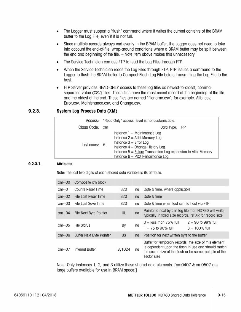
64059110 | 12 | 04/2018 METTLER TOLEDO IND780 Shared Data Reference 9-15
• The Logger must support a “flush” command where it writes the current contents of the BRAM buffer to the Log File, even if it is not full.
• Since multiple records always end evenly in the BRAM buffer, the Logger does not need to take into account the end-of-file, wrap-around conditions where a BRAM buffer may be split between the end and beginning of the file. – Note item above makes this unnecessary
• The Service Technician can use FTP to read the Log Files through FTP.
• When the Service Technician reads the Log Files through FTP, FTP issues a command to the Logger to flush the BRAM buffer to Compact Flash Log File before transmitting the Log File to the host.
• FTP Server provides READ-ONLY access to these log files as newest-to-oldest, comma-separated value (CSV) files. These files have the most recent record at the beginning of the file and the oldest at the end. These files are named “filename.csv”; for example, Alibi.csv, Error.csv, Maintenance.csv, and Change.csv.
9.2.3. System Log Process Data (XM)
Access: “Read Only” access, level is not customizable.
Class Code: xm Data Type: PP
Instances: 6
Instance 1 = Maintenance Log Instance 2 = Alibi Memory Log Instance 3 = Error Log Instance 4 = Change History Log Instance 5 = Future Transaction Log expansion to Alibi Memory Instance 6 = PDX Performance Log
9.2.3.1. Attributes
Note: The last two digits of each shared data variable is its attribute.
xm--00 Composite xm block
xm--01 Counts Reset Time S20 na Date & time, where applicable
xm--02 File Last Reset Time S20 na Date & time
xm--03 File Last Save Time S20 na Date & time when last sent to host via FTP
xm--04 File Next Byte Pointer UL na Pointer to next byte in log file that IND780 will write, typically in fixed size records, ref XR for record size
xm--05 File Status By na 0 = less than 75% full
1 = 75 to 90% full
2 = 90 to 99% full
3 = 100% full
xm--06 Buffer Next Byte Pointer US na Position for next written byte to the buffer
xm--07 Internal Buffer By1024 na
Buffer for temporary records, the size of this element is dependent upon the flash in use and should match the sector size of the flash or be some multiple of the sector size
Note: Only instances 1, 2, and 3 utilize these shared data elements. [xm0407 & xm0507 are large buffers available for use in BRAM space.]
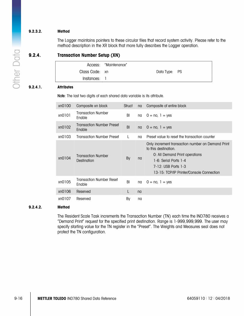
9-16 METTLER TOLEDO IND780 Shared Data Reference 64059110 | 12 | 04/2018
Oth
er D
ata
9.2.3.2. Method
The Logger maintains pointers to these circular files that record system activity. Please refer to the method description in the XR block that more fully describes the Logger operation.
9.2.4. Transaction Number Setup (XN)
Access: “Maintenance”
Class Code: xn Data Type: PS
Instances: 1
9.2.4.1. Attributes
Note: The last two digits of each shared data variable is its attribute.
xn0100 Composite xn block Struct na Composite of entire block
xn0101 Transaction Number Enable Bl na 0 = no, 1 = yes
xn0102 Transaction Number Preset Enable
Bl na 0 = no, 1 = yes
xn0103 Transaction Number Preset L na Preset value to reset the transaction counter
xn0104 Transaction Number Destination
By na
Only increment transaction number on Demand Print to this destination.
0: All Demand Print operations
1-6: Serial Ports 1-4
7-12: USB Ports 1-3
13-15: TCP/IP Printer/Console Connection
xn0105 Transaction Number Reset Enable
Bl na 0 = no, 1 = yes
xn0106 Reserved L na
xn0107 Reserved By na
9.2.4.2. Method
The Resident Scale Task increments the Transaction Number (TN) each time the IND780 receives a “Demand Print” request for the specified print destination. Range is 1-999,999,999. The user may specify starting value for the TN register in the “Preset”. The Weights and Measures seal does not protect the TN configuration.
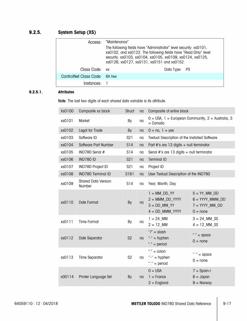
64059110 | 12 | 04/2018 METTLER TOLEDO IND780 Shared Data Reference 9-17
9.2.5. System Setup (XS)
Access: “Maintenance” The following fields have “Administrator” level security: xs0101, xs0102, and xs0122. The following fields have “Read Only” level security: xs0103, xs0104, xs0105, xs0109, xs0124, xs0125, xs0126, xs0127, xs0131, xs0151 and xs0152.
Class Code: xs Data Type: PS
ControlNet Class Code: 6A hex
Instances: 1
9.2.5.1. Attributes
Note: The last two digits of each shared data variable is its attribute.
Xs0100 Composite xs block Struct na Composite of entire block
xs0101 Market By na 0 = USA, 1 = European Community, 2 = Australia, 3 = Canada
xs0102 Legal for Trade By na 0 = no, 1 = yes
xs0103 Software ID S21 na Textual Description of the Installed Software
xs0104 Software Part Number S14 na Part #’s are 13 digits + null terminator
xs0105 IND780 Serial # S14 na Serial #’s are 13 digits + null terminator
xs0106 IND780 ID S21 na Terminal ID
xs0107 IND780 Project ID S21 na Project ID
xs0108 IND780 Terminal ID S161 na User Textual Description of the IND780
xs0109 Shared Data Version Number S14 na Year, Month, Day
xs0110 Date Format By na
1 = MM_DD_YY
2 = MMM_DD_YYYY
3 = DD_MM_YY
4 = DD_MMM_YYYY
5 = YY_MM_DD
6 = YYYY_MMM_DD
7 = YYYY_MM_DD
0 = none
xs0111 Time Format By na 1 = 24_MM
2 = 12_MM
3 = 24_MM_SS
4 = 12_MM_SS
xs0112 Date Separator S2 na
‘‘/” = slash
“-“ = hyphen
“.” = period
“ “ = space
0 = none
xs0113 Time Separator S2 na
“:” = colon
‘‘-‘‘ = hyphen
‘‘.’’ = period
‘‘ ‘‘ = space
0 = none
x00114 Printer Language Set By na
0 = USA
1 = France
2 = England
7 = Spain-I
8 = Japan
9 = Norway
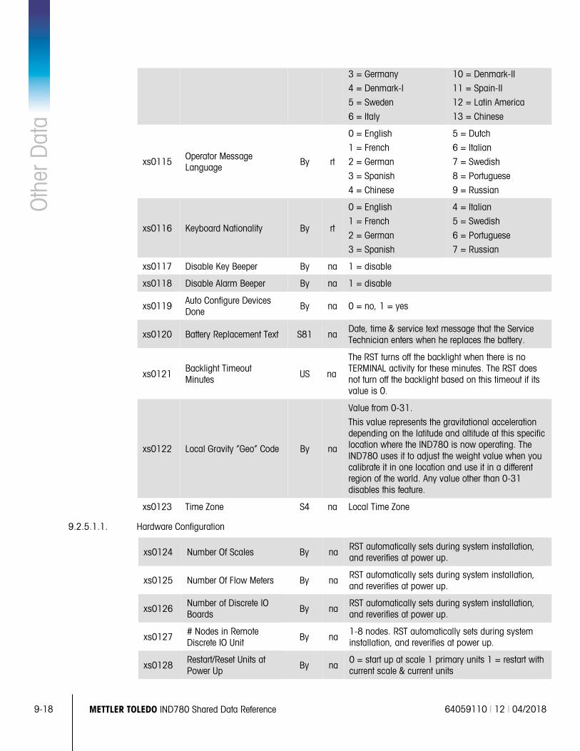
9-18 METTLER TOLEDO IND780 Shared Data Reference 64059110 | 12 | 04/2018
Oth
er D
ata
3 = Germany
4 = Denmark-I
5 = Sweden
6 = Italy
10 = Denmark-II
11 = Spain-II
12 = Latin America
13 = Chinese
xs0115 Operator Message Language
By rt
0 = English
1 = French
2 = German
3 = Spanish
4 = Chinese
5 = Dutch
6 = Italian
7 = Swedish
8 = Portuguese
9 = Russian
xs0116 Keyboard Nationality By rt
0 = English
1 = French
2 = German
3 = Spanish
4 = Italian
5 = Swedish
6 = Portuguese
7 = Russian
xs0117 Disable Key Beeper By na 1 = disable
xs0118 Disable Alarm Beeper By na 1 = disable
xs0119 Auto Configure Devices Done
By na 0 = no, 1 = yes
xs0120 Battery Replacement Text S81 na Date, time & service text message that the Service Technician enters when he replaces the battery.
xs0121 Backlight Timeout Minutes US na
The RST turns off the backlight when there is no TERMINAL activity for these minutes. The RST does not turn off the backlight based on this timeout if its value is 0.
xs0122 Local Gravity “Geo” Code By na
Value from 0-31.
This value represents the gravitational acceleration depending on the latitude and altitude at this specific location where the IND780 is now operating. The IND780 uses it to adjust the weight value when you calibrate it in one location and use it in a different region of the world. Any value other than 0-31 disables this feature.
xs0123 Time Zone S4 na Local Time Zone
9.2.5.1.1. Hardware Configuration
xs0124 Number Of Scales By na RST automatically sets during system installation, and reverifies at power up.
xs0125 Number Of Flow Meters By na RST automatically sets during system installation, and reverifies at power up.
xs0126 Number of Discrete IO Boards By na
RST automatically sets during system installation, and reverifies at power up.
xs0127 # Nodes in Remote Discrete IO Unit
By na 1-8 nodes. RST automatically sets during system installation, and reverifies at power up.
xs0128 Restart/Reset Units at Power Up By na
0 = start up at scale 1 primary units 1 = restart with current scale & current units
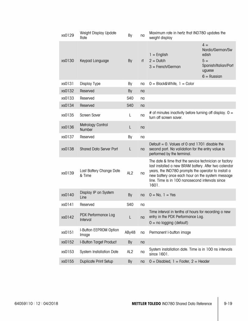
64059110 | 12 | 04/2018 METTLER TOLEDO IND780 Shared Data Reference 9-19
xs0129 Weight Display Update Rate By na
Maximum rate in hertz that IND780 updates the weight display
xs0130 Keypad Language By rt
1 = English
2 = Dutch
3 = French/German
4 = Nordic/German/Swedish
5 = Spanish/Italian/Portuguese
6 = Russian
xs0131 Display Type By na 0 = Black&White, 1 = Color
xs0132 Reserved By na
xs0133 Reserved S40 na
xs0134 Reserved S40 na
xs0135 Screen Saver L na # of minutes inactivity before turning off display. 0 = turn off screen saver.
xs0136 Metrology Control Number
L na
xs0137 Reserved By na
xs0138 Shared Data Server Port L na Default = 0. Values of 0 and 1701 disable the second port. No validation for the entry value is performed by the terminal.
xs0139 Last Battery Change Date & Time
AL2 na
The date & time that the service technician or factory last installed a new BRAM battery. After two calendar years, the IND780 prompts the operator to install a new battery once each hour on the system message line. Time is in 100 nanosecond intervals since 1601.
xs0140 Display IP on System Line
By na 0 = No, 1 = Yes
xs0141 Reserved S40 na
xs0142 PDX Performance Log Interval
L na Time interval in tenths of hours for recording a new entry in the PDX Performance Log.
0 = no logging (default)
xs0151 I-Button EEPROM Option Image ABy48 na Permanent I-button image
xs0152 I-Button Target Product By na
xs0153 System Installation Date AL2 na System installation date. Time is in 100 ns intervals since 1601.
xs0155 Duplicate Print Setup By na 0 = Disabled, 1 = Footer, 2 = Header
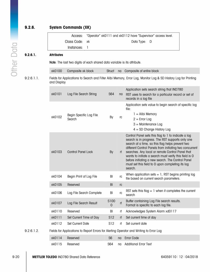
9-20 METTLER TOLEDO IND780 Shared Data Reference 64059110 | 12 | 04/2018
Oth
er D
ata
9.2.6. System Commands (XK)
Access: “Operator” xk0111 and xk0112 have “Supervisor” access level.
Class Code: xk Data Type: D
Instances: 1
9.2.6.1. Attributes
Note: The last two digits of each shared data variable is its attribute.
xk0100 Composite xk block Struct na Composite of entire block
9.2.6.1.1. Fields for Applications to Search and Filter Alibi Memory, Error Log, Monitor Log & SD History Log for Printing and Display
xk0101 Log File Search String S64 na Application sets search string that IND780
RST uses to search for a particular record or set of records in a log file
xk0102 Begin Specific Log File Search
By rc
Application sets value to begin search of specific log file:
1 = Alibi Memory
2 = Error Log
3 = Maintenance Log
4 = SD Change History Log
xk0103 Control Panel Lock By rt
Control Panel sets this flag to 1 to indicate a log search is in progress. The RST supports only one search at a time, so this flag helps prevent two different Control Panels from initiating two concurrent searches. Any local or remote Control Panel that wants to initiate a search must verify this field is 0 before initiating a new search. The Control Panel must set this field to 0 upon completing its log search.
xk0104 Begin Print of Log File Bl rc When application sets = 1, RST begins printing log file based on current search parameters.
xk0105 Reserved Bl rc
xk0106 Log File Search Complete Bl rc RST sets this flag = 1 when it completes the current search
xk0107 Log File Search Result S100
0 rt
Buffer containing Log File search results. Format is specific to each log file.
xk0110 Reserved Bl rt Acknowledges System Alarm xd0117
xk0111 Set Current Time of Day S12 rt Set current time of day
xk0112 Set Current Date S12 rt Set current date
9.2.6.1.2. Fields for Applications to Report Errors for Alerting Operator and Writing to Error Log
xk0114 Reserved S6 na Error Code
xk0115 Reserved S64 na Additional Error Text
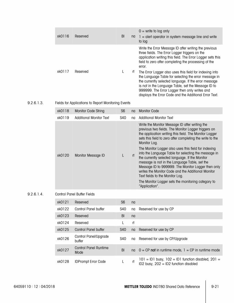
64059110 | 12 | 04/2018 METTLER TOLEDO IND780 Shared Data Reference 9-21
xk0116 Reserved Bl na 0 = write to log only
1 = alert operator in system message line and write to log
xk0117 Reserved L rt
Write the Error Message ID after writing the previous three fields. The Error Logger triggers on the application writing this field. The Error Logger sets this field to zero after completing the processing of the error.
The Error Logger also uses this field for indexing into the Language Table for selecting the error message in the currently selected language. If the error message is not in the Language Table, set the Message ID to 999999. The Error Logger then only writes and displays the Error Code and the Additional Error Text.
9.2.6.1.3. Fields for Applications to Report Monitoring Events
xk0118 Monitor Code String S6 na Monitor Code
xk0119 Additional Monitor Text S40 na Additional Monitor Text
xk0120 Monitor Message ID L rt
Write the Monitor Message ID after writing the previous two fields. The Monitor Logger triggers on the application writing this field. The Monitor Logger sets this field to zero after completing the write to the Monitor Log.
The Monitor Logger also uses this field for indexing into the Language Table for selecting the message in the currently selected language. If the Monitor message is not in the Language Table, set the Message ID to 999999. The Monitor Logger then only writes the Monitor Code and the Additional Monitor Text fields to the Monitor Log.
The Monitor Logger sets the monitoring category to “Application”.
9.2.6.1.4. Control Panel Buffer Fields
xk0121 Reserved S6 na
xk0122 Control Panel buffer S40 na Reserved for use by CP
xk0123 Reserved Bl na
xk0124 Reserved L rt
xk0125 Control Panel buffer S40 na Reserved for use by CP
xk0126 Control Panel/Upgrade buffer S40 na Reserved for use by CP/Upgrade
xk0127 Control Panel Runtime Mode
Bl na 0 = CP not in runtime mode, 1 = CP in runtime mode
xk0128 IDPrompt Error Code L rt 101 = ID1 busy, 102 = ID1 function disabled, 201 = ID2 busy, 202 = ID2 function disabled
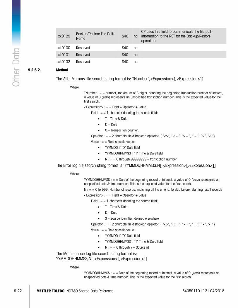
9-22 METTLER TOLEDO IND780 Shared Data Reference 64059110 | 12 | 04/2018
Oth
er D
ata
xk0129 Backup/Restore File Path Name
S40 na CP uses this field to communicate the file path information to the RST for the Backup/Restore operation.
xk0130 Reserved S40 na
xk0131 Reserved S40 na
xk0132 Reserved S40 na
9.2.6.2. Method
The Alibi Memory file search string format is: TNumber[,<Expression>[,<Expression>]]
Where:
TNumber : = = number, maximum of 8 digits, denoting the beginning transaction number of interest, a value of 0 (zero) represents an unspecified transaction number. This is the expected value for the first search.
<Expression> : = = Field + Operator + Value
Field : = = 1 character denoting the search field:
• T – Time & Date
• D – Date
• C – Transaction counter.
Operator : = = 2 character field Boolean operator: { “<>”, “< = ”, “> = ”, “ = “, “> “, “< “}
Value : = = Field specific value:
• YYMMDD if “D” Date field
• YYMMDDHHMMSS if “T” Time & Date field
• N : = = 0 through 99999999 – transaction number
The Error log file search string format is: YYMMDDHHMMSS,N[,<Expression>[,<Expression>]]
Where:
YYMMDDHHMMSS : = = Date of the beginning record of interest, a value of 0 (zero) represents an unspecified date & time number. This is the expected value for the first search.
N : = = 0 to 999, Number of records, matching all the criteria, to skip before returning result records
<Expression> : = = Field + Operator + Value
Field : = = 1 character denoting the search field:
• T – Time & Date
• D – Date
• S – Source identifier, defined elsewhere
Operator : = = 2 character field Boolean operator: { “<>”, “< = ”, “> = ”, “ = “, “> “, “< “}
Value : = = Field specific value:
• YYMMDD if “D” Date field
• YYMMDDHHMMSS if “T” Time & Date field
• N : = = 0 through ? – Source id
The Maintenance log file search string format is: YYMMDDHHMMSS,N[,<Expression>[,<Expression>]]
Where:
YYMMDDHHMMSS : = = Date of the beginning record of interest, a value of 0 (zero) represents an unspecified date & time number. This is the expected value for the first search.
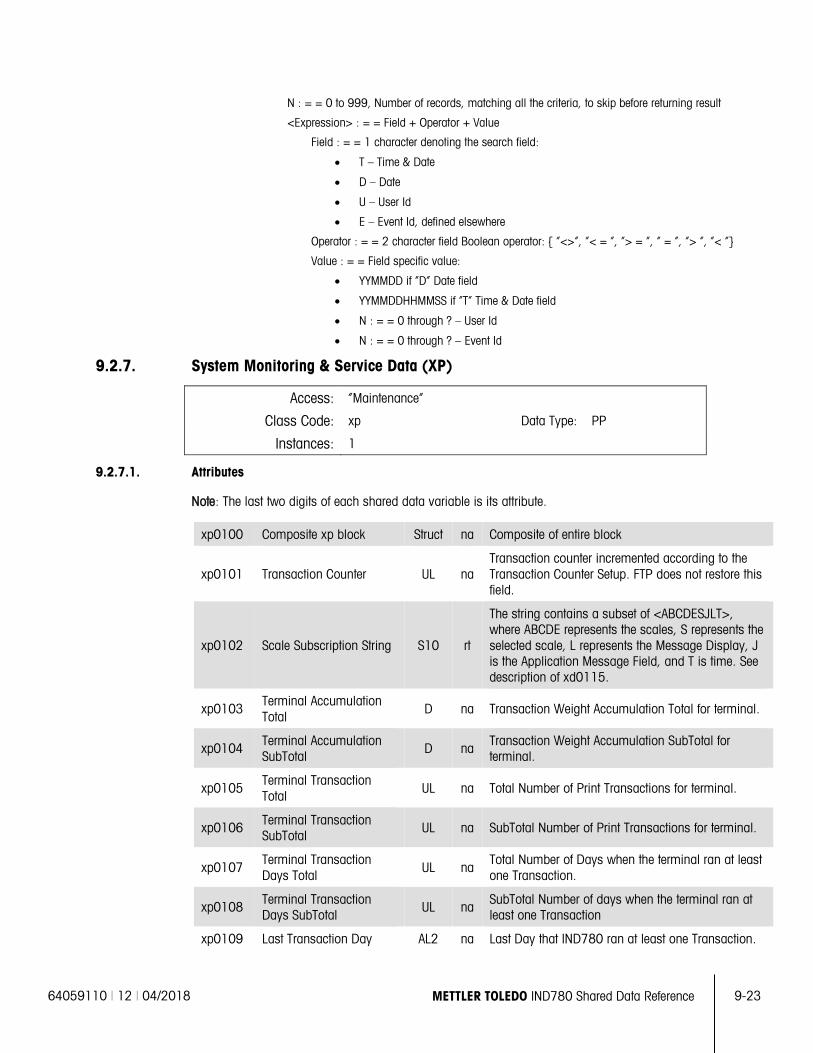
64059110 | 12 | 04/2018 METTLER TOLEDO IND780 Shared Data Reference 9-23
N : = = 0 to 999, Number of records, matching all the criteria, to skip before returning result
<Expression> : = = Field + Operator + Value
Field : = = 1 character denoting the search field:
• T – Time & Date
• D – Date
• U – User Id
• E – Event Id, defined elsewhere
Operator : = = 2 character field Boolean operator: { “<>”, “< = ”, “> = ”, “ = “, “> “, “< “}
Value : = = Field specific value:
• YYMMDD if “D” Date field
• YYMMDDHHMMSS if “T” Time & Date field
• N : = = 0 through ? – User Id
• N : = = 0 through ? – Event Id
9.2.7. System Monitoring & Service Data (XP)
Access: “Maintenance”
Class Code: xp Data Type: PP
Instances: 1
9.2.7.1. Attributes
Note: The last two digits of each shared data variable is its attribute.
xp0100 Composite xp block Struct na Composite of entire block
xp0101 Transaction Counter UL na Transaction counter incremented according to the Transaction Counter Setup. FTP does not restore this field.
xp0102 Scale Subscription String S10 rt
The string contains a subset of <ABCDESJLT>, where ABCDE represents the scales, S represents the selected scale, L represents the Message Display, J is the Application Message Field, and T is time. See description of xd0115.
xp0103 Terminal Accumulation Total
D na Transaction Weight Accumulation Total for terminal.
xp0104 Terminal Accumulation SubTotal
D na Transaction Weight Accumulation SubTotal for terminal.
xp0105 Terminal Transaction Total
UL na Total Number of Print Transactions for terminal.
xp0106 Terminal Transaction SubTotal
UL na SubTotal Number of Print Transactions for terminal.
xp0107 Terminal Transaction Days Total
UL na Total Number of Days when the terminal ran at least one Transaction.
xp0108 Terminal Transaction Days SubTotal
UL na SubTotal Number of days when the terminal ran at least one Transaction
xp0109 Last Transaction Day AL2 na Last Day that IND780 ran at least one Transaction.
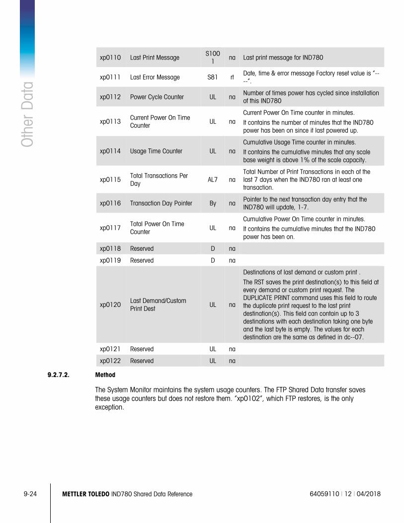
9-24 METTLER TOLEDO IND780 Shared Data Reference 64059110 | 12 | 04/2018
Oth
er D
ata
xp0110 Last Print Message S100
1 na Last print message for IND780
xp0111 Last Error Message S81 rt Date, time & error message Factory reset value is “----“.
xp0112 Power Cycle Counter UL na Number of times power has cycled since installation of this IND780
xp0113 Current Power On Time Counter
UL na Current Power On Time counter in minutes.
It contains the number of minutes that the IND780 power has been on since it last powered up.
xp0114 Usage Time Counter UL na Cumulative Usage Time counter in minutes.
It contains the cumulative minutes that any scale base weight is above 1% of the scale capacity.
xp0115 Total Transactions Per Day
AL7 na Total Number of Print Transactions in each of the last 7 days when the IND780 ran at least one transaction.
xp0116 Transaction Day Pointer By na Pointer to the next transaction day entry that the IND780 will update, 1-7.
xp0117 Total Power On Time Counter
UL na Cumulative Power On Time counter in minutes.
It contains the cumulative minutes that the IND780 power has been on.
xp0118 Reserved D na
xp0119 Reserved D na
xp0120 Last Demand/Custom Print Dest
UL na
Destinations of last demand or custom print .
The RST saves the print destination(s) to this field at every demand or custom print request. The DUPLICATE PRINT command uses this field to route the duplicate print request to the last print destination(s). This field can contain up to 3 destinations with each destination taking one byte and the last byte is empty. The values for each destination are the same as defined in dc--07.
xp0121 Reserved UL na
xp0122 Reserved UL na
9.2.7.2. Method
The System Monitor maintains the system usage counters. The FTP Shared Data transfer saves these usage counters but does not restore them. “xp0102”, which FTP restores, is the only exception.
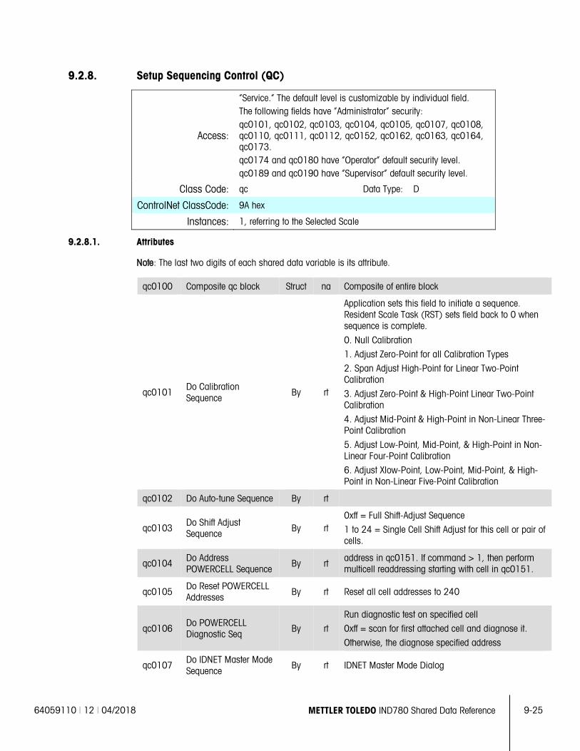
64059110 | 12 | 04/2018 METTLER TOLEDO IND780 Shared Data Reference 9-25
9.2.8. Setup Sequencing Control (QC)
Access:
“Service.” The default level is customizable by individual field. The following fields have “Administrator” security: qc0101, qc0102, qc0103, qc0104, qc0105, qc0107, qc0108, qc0110, qc0111, qc0112, qc0152, qc0162, qc0163, qc0164, qc0173. qc0174 and qc0180 have “Operator” default security level. qc0189 and qc0190 have “Supervisor” default security level.
Class Code: qc Data Type: D
ControlNet ClassCode: 9A hex
Instances: 1, referring to the Selected Scale
9.2.8.1. Attributes
Note: The last two digits of each shared data variable is its attribute.
qc0100 Composite qc block Struct na Composite of entire block
qc0101 Do Calibration Sequence
By rt
Application sets this field to initiate a sequence. Resident Scale Task (RST) sets field back to 0 when sequence is complete.
0. Null Calibration
1. Adjust Zero-Point for all Calibration Types
2. Span Adjust High-Point for Linear Two-Point Calibration
3. Adjust Zero-Point & High-Point Linear Two-Point Calibration
4. Adjust Mid-Point & High-Point in Non-Linear Three-Point Calibration
5. Adjust Low-Point, Mid-Point, & High-Point in Non-Linear Four-Point Calibration
6. Adjust Xlow-Point, Low-Point, Mid-Point, & High-Point in Non-Linear Five-Point Calibration
qc0102 Do Auto-tune Sequence By rt
qc0103 Do Shift Adjust Sequence By rt
0xff = Full Shift-Adjust Sequence
1 to 24 = Single Cell Shift Adjust for this cell or pair of cells.
qc0104 Do Address POWERCELL Sequence
By rt address in qc0151. If command > 1, then perform multicell readdressing starting with cell in qc0151.
qc0105 Do Reset POWERCELL Addresses By rt Reset all cell addresses to 240
qc0106 Do POWERCELL Diagnostic Seq By rt
Run diagnostic test on specified cell
0xff = scan for first attached cell and diagnose it.
Otherwise, the diagnose specified address
qc0107 Do IDNET Master Mode Sequence
By rt IDNET Master Mode Dialog
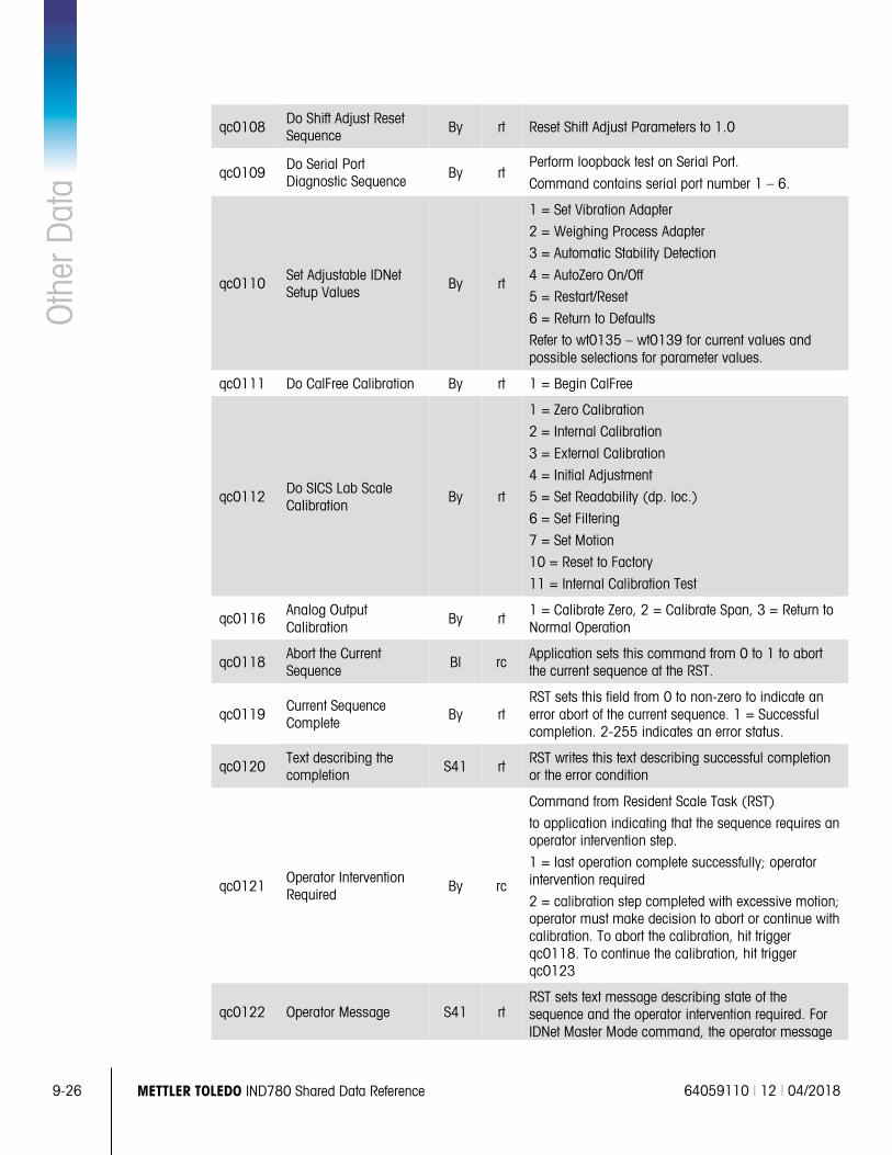
9-26 METTLER TOLEDO IND780 Shared Data Reference 64059110 | 12 | 04/2018
Oth
er D
ata
qc0108 Do Shift Adjust Reset Sequence By rt Reset Shift Adjust Parameters to 1.0
qc0109 Do Serial Port Diagnostic Sequence By rt
Perform loopback test on Serial Port.
Command contains serial port number 1 – 6.
qc0110 Set Adjustable IDNet Setup Values
By rt
1 = Set Vibration Adapter
2 = Weighing Process Adapter
3 = Automatic Stability Detection
4 = AutoZero On/Off
5 = Restart/Reset
6 = Return to Defaults
Refer to wt0135 – wt0139 for current values and possible selections for parameter values.
qc0111 Do CalFree Calibration By rt 1 = Begin CalFree
qc0112 Do SICS Lab Scale Calibration
By rt
1 = Zero Calibration
2 = Internal Calibration
3 = External Calibration
4 = Initial Adjustment
5 = Set Readability (dp. loc.)
6 = Set Filtering
7 = Set Motion
10 = Reset to Factory
11 = Internal Calibration Test
qc0116 Analog Output Calibration
By rt 1 = Calibrate Zero, 2 = Calibrate Span, 3 = Return to Normal Operation
qc0118 Abort the Current Sequence Bl rc
Application sets this command from 0 to 1 to abort the current sequence at the RST.
qc0119 Current Sequence Complete By rt
RST sets this field from 0 to non-zero to indicate an error abort of the current sequence. 1 = Successful completion. 2-255 indicates an error status.
qc0120 Text describing the completion S41 rt
RST writes this text describing successful completion or the error condition
qc0121 Operator Intervention Required By rc
Command from Resident Scale Task (RST)
to application indicating that the sequence requires an operator intervention step.
1 = last operation complete successfully; operator intervention required
2 = calibration step completed with excessive motion; operator must make decision to abort or continue with calibration. To abort the calibration, hit trigger qc0118. To continue the calibration, hit trigger qc0123
qc0122 Operator Message S41 rt RST sets text message describing state of the sequence and the operator intervention required. For IDNet Master Mode command, the operator message
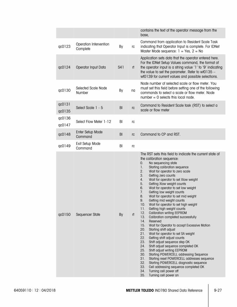
64059110 | 12 | 04/2018 METTLER TOLEDO IND780 Shared Data Reference 9-27
contains the text of the operator message from the base,
qc0123 Operation Intervention Complete By rc
Command from application to Resident Scale Task indicating that Operator Input is complete. For IDNet Master Mode sequence: 1 = Yes, 2 = No
qc0124 Operator Input Data S41 rt
Application sets data that the operator entered here. For the IDNet Setup Values command, the format of the operator input is a string value ‘1’ to ‘9’ indicating the value to set the parameter. Refer to wt0135 – wt0139 for current values and possible selections.
qc0130 Selected Scale Node Number
By na
Node number of selected scale or flow meter. You must set this field before setting one of the following commands to select a scale or flow meter. Node number = 0 selects this local node.
qc0131 Select Scale 1 - 5 Bl rc
Command to Resident Scale task (RST) to select a scale or flow meter qc0135
qc0136 Select Flow Meter 1-12 Bl rc
qc0147
qc0148 Enter Setup Mode Command
Bl rc Command to CP and RST.
qc0149 Exit Setup Mode Command Bl rc
qc0150 Sequencer State By rt
The RST sets this field to indicate the current state of the calibration sequence: 0. No sequencing state 1. Starting calibration sequence 2. Wait for operator to zero scale 3. Getting zero counts 4. Wait for operator to set Xlow weight 5. Getting Xlow weight counts 6. Wait for operator to set low weight 7. Getting low weight counts 8. Wait for operator to set mid weight 9. Getting mid weight counts 10. Wait for operator to set high weight 11. Getting high weight counts 12. Calibration writing EEPROM 13. Calibration completed successfully 14. Reserved 15. Wait for Operator to accept Excessive Motion 20. Starting shift adjust 21. Wait for operator to set SA weight 22. Getting shift adjust counts 23. Shift adjust sequence step OK 24. Shift adjust sequence completed OK 25. Shift adjust writing EEPROM 30. Starting POWERCELL addressing Sequence 31. Starting reset POWERCELL addresses sequence 32. Starting POWERCELL diagnostic sequence 33. Cell addressing sequence completed OK 34. Turning cell power off 35. Turning cell power on
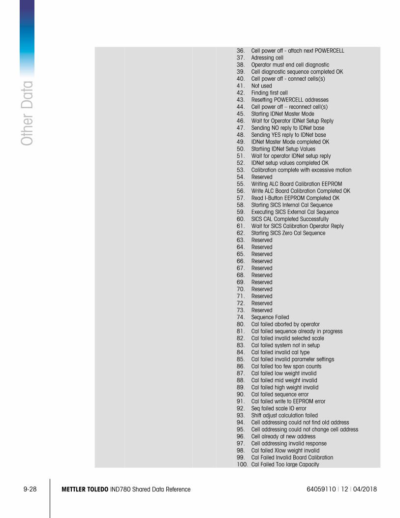
9-28 METTLER TOLEDO IND780 Shared Data Reference 64059110 | 12 | 04/2018
Oth
er D
ata
36. Cell power off - attach next POWERCELL 37. Adressing cell 38. Operator must end cell diagnostic 39. Cell diagnostic sequence completed OK 40. Cell power off - connect cells(s) 41. Not used 42. Finding first cell 43. Resetting POWERCELL addresses 44. Cell power off – reconnect cell(s) 45. Starting IDNet Master Mode 46. Wait for Operator IDNet Setup Reply 47. Sending NO reply to IDNet base 48. Sending YES reply to IDNet base 49. IDNet Master Mode completed OK 50. Startiing IDNet Setup Values 51. Wait for operator IDNet setup reply 52. IDNet setup values completed OK 53. Calibration complete with excessive motion 54. Reserved 55. Writing ALC Board Calibration EEPROM 56. Write ALC Board Calibration Completed OK 57. Read I-Button EEPROM Completed OK 58. Starting SICS Internal Cal Sequence 59. Executing SICS External Cal Sequence 60. SICS CAL Completed Successfully 61. Wait for SICS Calibration Operator Reply 62. Starting SICS Zero Cal Sequence 63. Reserved 64. Reserved 65. Reserved 66. Reserved 67. Reserved 68. Reserved 69. Reserved 70. Reserved 71. Reserved 72. Reserved 73. Reserved 74. Sequence Failed 80. Cal failed aborted by operator 81. Cal failed sequence already in progress 82. Cal failed invalid selected scale 83. Cal failed system not in setup 84. Cal failed invalid cal type 85. Cal failed invalid parameter settings 86. Cal failed too few span counts 87. Cal failed low weight invalid 88. Cal failed mid weight invalid 89. Cal failed high weight invalid 90. Cal failed sequence error 91. Cal failed write to EEPROM error 92. Seq failed scale IO error 93. Shift adjust calculation failed 94. Cell addressing could not find old address 95. Cell addressing could not change cell address 96. Cell already at new address 97. Cell addressing invalid response 98. Cal failed Xlow weight invalid 99. Cal Failed Invalid Board Calibration 100. Cal Failed Too large Capacity
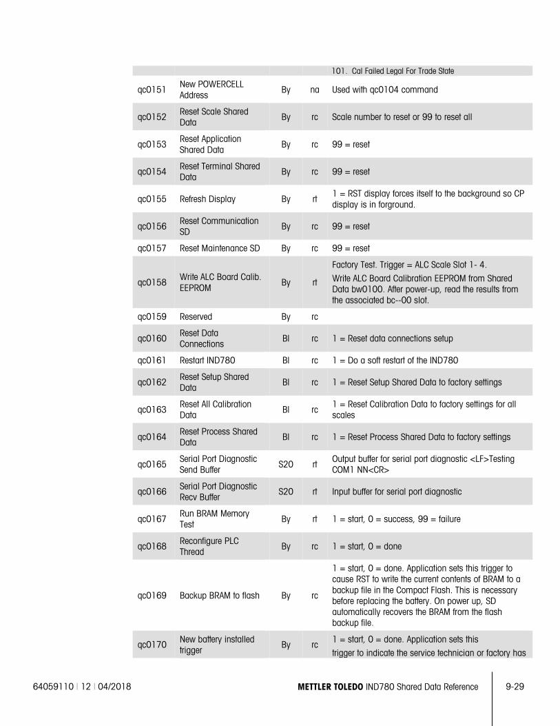
64059110 | 12 | 04/2018 METTLER TOLEDO IND780 Shared Data Reference 9-29
101. Cal Failed Legal For Trade State
qc0151 New POWERCELL Address
By na Used with qc0104 command
qc0152 Reset Scale Shared Data
By rc Scale number to reset or 99 to reset all
qc0153 Reset Application Shared Data
By rc 99 = reset
qc0154 Reset Terminal Shared Data
By rc 99 = reset
qc0155 Refresh Display By rt 1 = RST display forces itself to the background so CP display is in forground.
qc0156 Reset Communication SD
By rc 99 = reset
qc0157 Reset Maintenance SD By rc 99 = reset
qc0158 Write ALC Board Calib. EEPROM
By rt
Factory Test. Trigger = ALC Scale Slot 1- 4.
Write ALC Board Calibration EEPROM from Shared Data bw0100. After power-up, read the results from the associated bc--00 slot.
qc0159 Reserved By rc
qc0160 Reset Data Connections
Bl rc 1 = Reset data connections setup
qc0161 Restart IND780 Bl rc 1 = Do a soft restart of the IND780
qc0162 Reset Setup Shared Data
Bl rc 1 = Reset Setup Shared Data to factory settings
qc0163 Reset All Calibration Data Bl rc
1 = Reset Calibration Data to factory settings for all scales
qc0164 Reset Process Shared Data
Bl rc 1 = Reset Process Shared Data to factory settings
qc0165 Serial Port Diagnostic Send Buffer S20 rt
Output buffer for serial port diagnostic <LF>Testing COM1 NN<CR>
qc0166 Serial Port Diagnostic Recv Buffer
S20 rt Input buffer for serial port diagnostic
qc0167 Run BRAM Memory Test By rt 1 = start, 0 = success, 99 = failure
qc0168 Reconfigure PLC Thread
By rc 1 = start, 0 = done
qc0169 Backup BRAM to flash By rc
1 = start, 0 = done. Application sets this trigger to cause RST to write the current contents of BRAM to a backup file in the Compact Flash. This is necessary before replacing the battery. On power up, SD automatically recovers the BRAM from the flash backup file.
qc0170 New battery installed trigger
By rc 1 = start, 0 = done. Application sets this
trigger to indicate the service technician or factory has
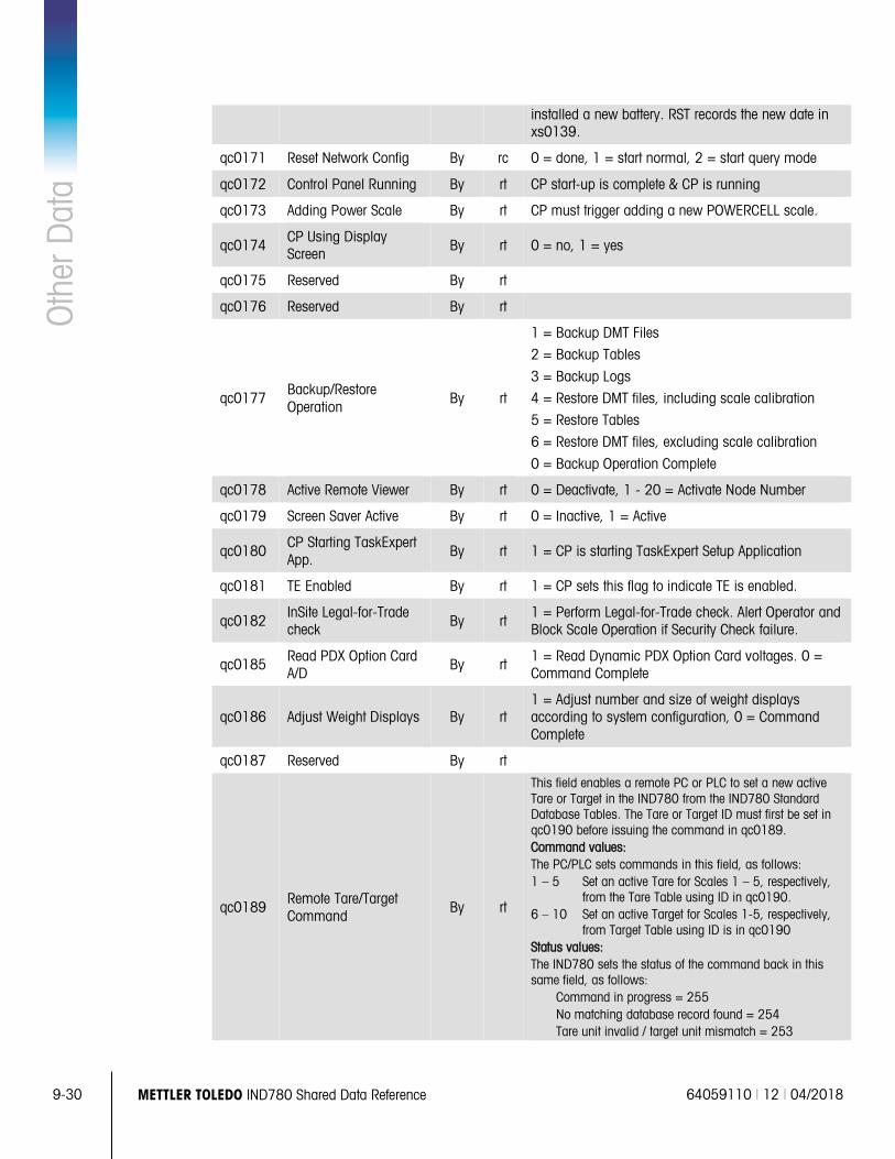
9-30 METTLER TOLEDO IND780 Shared Data Reference 64059110 | 12 | 04/2018
Oth
er D
ata
installed a new battery. RST records the new date in xs0139.
qc0171 Reset Network Config By rc 0 = done, 1 = start normal, 2 = start query mode
qc0172 Control Panel Running By rt CP start-up is complete & CP is running
qc0173 Adding Power Scale By rt CP must trigger adding a new POWERCELL scale.
qc0174 CP Using Display Screen By rt 0 = no, 1 = yes
qc0175 Reserved By rt
qc0176 Reserved By rt
qc0177 Backup/Restore Operation
By rt
1 = Backup DMT Files
2 = Backup Tables
3 = Backup Logs
4 = Restore DMT files, including scale calibration
5 = Restore Tables
6 = Restore DMT files, excluding scale calibration
0 = Backup Operation Complete
qc0178 Active Remote Viewer By rt 0 = Deactivate, 1 - 20 = Activate Node Number
qc0179 Screen Saver Active By rt 0 = Inactive, 1 = Active
qc0180 CP Starting TaskExpert App.
By rt 1 = CP is starting TaskExpert Setup Application
qc0181 TE Enabled By rt 1 = CP sets this flag to indicate TE is enabled.
qc0182 InSite Legal-for-Trade check By rt
1 = Perform Legal-for-Trade check. Alert Operator and Block Scale Operation if Security Check failure.
qc0185 Read PDX Option Card A/D
By rt 1 = Read Dynamic PDX Option Card voltages. 0 = Command Complete
qc0186 Adjust Weight Displays By rt 1 = Adjust number and size of weight displays according to system configuration, 0 = Command Complete
qc0187 Reserved By rt
qc0189 Remote Tare/Target Command
By rt
This field enables a remote PC or PLC to set a new active Tare or Target in the IND780 from the IND780 Standard Database Tables. The Tare or Target ID must first be set in qc0190 before issuing the command in qc0189. Command values: The PC/PLC sets commands in this field, as follows: 1 – 5 Set an active Tare for Scales 1 – 5, respectively,
from the Tare Table using ID in qc0190. 6 – 10 Set an active Target for Scales 1-5, respectively,
from Target Table using ID is in qc0190 Status values: The IND780 sets the status of the command back in this same field, as follows:
Command in progress = 255 No matching database record found = 254 Tare unit invalid / target unit mismatch = 253
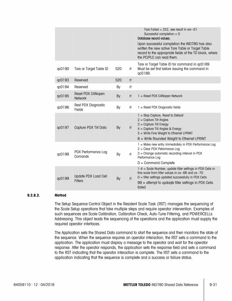
64059110 | 12 | 04/2018 METTLER TOLEDO IND780 Shared Data Reference 9-31
Tare Failed = 252, see result in wx--01 Successful completion = 0
Database record values:
Upon successful completion the IND780 has also written the new active Tare Table or Target Table record to the appropriate fields of the TD block, where the PC/PLC can read them.
qc0190 Tare or Target Table ID S20 rt Tare or Target Table ID for command in qc0189. Must be set first before issuing the command in qc0189.
qc0193 Reserved S20 rt
qc0194 Reserved By rt
qc0195 Reset PDX CANopen Network By rt 1 = Reset PDX CANopen Network
qc0196 Rest PDX Diagnostic Fields
By rt 1 = Reset PDX Diagnostic fields
qc0197 Capture PDX Tilt Data By rt
1 = Stop Capture, Reset to Default 2 = Capture Tilt Angles 3 = Capture Tilt Energy 4 = Capture Tilt Angles & Energy 5 = Write Fine Weight to Ethernet LPRINT
6 = Write Rounded Weight to Ethernet LPRINT
qc0198 PDX Performance Log Comands By rt
1 = Make new entry immediately in PDX Performance Log 2 = Clear PDX Peformance Log 3 = Change automatic recording interval in PDX Performance Log
0 = Command Complete
qc0199 Update PDX Load Cell Filters
By rt
1-4 = Scale Number; update filter settings in PDX Cells in this scale from filter values in cs--66 and cs--70 0 = filter settings updated successfully in PDX Cells
99 = attempt to updaqte filter settings in PDX Cells failed
9.2.8.2. Method
The Setup Sequence Control Object in the Resident Scale Task (RST) manages the sequencing of the Scale Setup operations that take multiple steps and require operator intervention. Examples of such sequences are Scale Calibration, Calibration Check, Auto-Tune Filtering, and POWERCELLs Addressing. This object leads the sequencing of the operations and the application must supply the required operator interfaces.
The Application sets the Shared Data command to start the sequence and then monitors the state of the sequence. When the sequence requires an operator interaction, the RST sets a command to the application. The application must display a message to the operator and wait for the operator response. After the operator responds, the application sets the response field and sets a command to the RST indicating that the operator interaction is complete. The RST sets a command to the application indicating that the sequence is complete and a success or failure status.
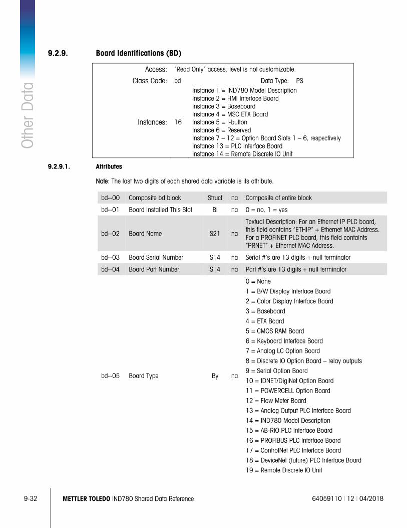
9-32 METTLER TOLEDO IND780 Shared Data Reference 64059110 | 12 | 04/2018
Oth
er D
ata
9.2.9. Board Identifications (BD)
Access: “Read Only” access, level is not customizable.
Class Code: bd Data Type: PS
Instances: 16
Instance 1 = IND780 Model Description Instance 2 = HMI Interface Board Instance 3 = Baseboard Instance 4 = MSC ETX Board Instance 5 = I-button Instance 6 = Reserved Instance 7 – 12 = Option Board Slots 1 – 6, respectively Instance 13 = PLC Interface Board Instance 14 = Remote Discrete IO Unit
9.2.9.1. Attributes
Note: The last two digits of each shared data variable is its attribute.
bd--00 Composite bd block Struct na Composite of entire block
bd--01 Board Installed This Slot Bl na 0 = no, 1 = yes
bd--02 Board Name S21 na
Textual Description: For an Ethernet IP PLC board, this field contains “ETHIP” + Ethernet MAC Address. For a PROFINET PLC board, this field containts “PRNET” + Ethernet MAC Address.
bd--03 Board Serial Number S14 na Serial #’s are 13 digits + null terminator
bd--04 Board Part Number S14 na Part #’s are 13 digits + null terminator
bd--05 Board Type By na
0 = None
1 = B/W Display Interface Board
2 = Color Display Interface Board
3 = Baseboard
4 = ETX Board
5 = CMOS RAM Board
6 = Keyboard Interface Board
7 = Analog LC Option Board
8 = Discrete IO Option Board – relay outputs
9 = Serial Option Board
10 = IDNET/DigiNet Option Board
11 = POWERCELL Option Board
12 = Flow Meter Board
13 = Analog Output PLC Interface Board
14 = IND780 Model Description
15 = AB-RIO PLC Interface Board
16 = PROFIBUS PLC Interface Board
17 = ControlNet PLC Interface Board
18 = DeviceNet (future) PLC Interface Board
19 = Remote Discrete IO Unit
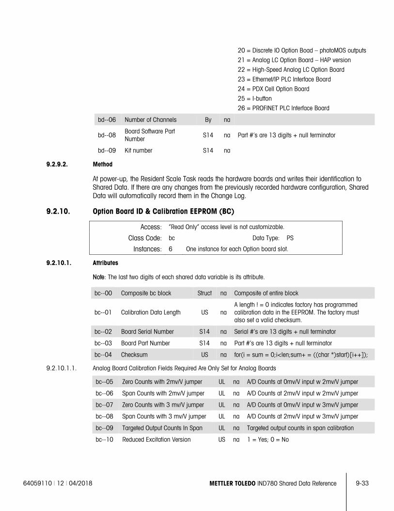
64059110 | 12 | 04/2018 METTLER TOLEDO IND780 Shared Data Reference 9-33
20 = Discrete IO Option Boad – photoMOS outputs
21 = Analog LC Option Board – HAP version
22 = High-Speed Analog LC Option Board
23 = Ethernet/IP PLC Interface Board
24 = PDX Cell Option Board
25 = I-button
26 = PROFINET PLC Interface Board
bd--06 Number of Channels By na
bd--08 Board Software Part Number S14 na Part #’s are 13 digits + null terminator
bd--09 Kit number S14 na
9.2.9.2. Method
At power-up, the Resident Scale Task reads the hardware boards and writes their identification to Shared Data. If there are any changes from the previously recorded hardware configuration, Shared Data will automatically record them in the Change Log.
9.2.10. Option Board ID & Calibration EEPROM (BC)
Access: “Read Only” access level is not customizable.
Class Code: bc Data Type: PS
Instances: 6 One instance for each Option board slot.
9.2.10.1. Attributes
Note: The last two digits of each shared data variable is its attribute.
bc--00 Composite bc block Struct na Composite of entire block
bc--01 Calibration Data Length US na A length ! = 0 indicates factory has programmed calibration data in the EEPROM. The factory must also set a valid checksum.
bc--02 Board Serial Number S14 na Serial #’s are 13 digits + null terminator
bc--03 Board Part Number S14 na Part #’s are 13 digits + null terminator
bc--04 Checksum US na for(i = sum = 0;i<len;sum+ = ((char *)start)[i++]);
9.2.10.1.1. Analog Board Calibration Fields Required Are Only Set for Analog Boards
bc--05 Zero Counts with 2mv/V jumper UL na A/D Counts at 0mv/V input w 2mv/V jumper
bc--06 Span Counts with 2mv/V jumper UL na A/D Counts at 2mv/V input w 2mv/V jumper
bc--07 Zero Counts with 3 mv/V jumper UL na A/D Counts at 0mv/V input w 3mv/V jumper
bc--08 Span Counts with 3 mv/V jumper UL na A/D Counts at 2mv/V input w 3mv/V jumper
bc--09 Targeted Output Counts In Span UL na Targeted output counts in span calibration
bc--10 Reduced Excitation Version US na 1 = Yes; 0 = No
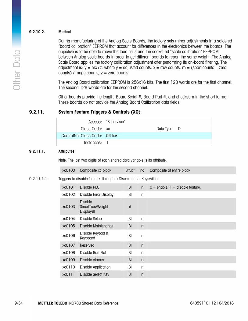
9-34 METTLER TOLEDO IND780 Shared Data Reference 64059110 | 12 | 04/2018
Oth
er D
ata
9.2.10.2. Method
During manufacturing of the Analog Scale Boards, the factory sets minor adjustments in a soldered “board calibration” EEPROM that account for differences in the electronics between the boards. The objective is to be able to move the load cells and the socket-ed “scale calibration” EEPROM between Analog scale boards in order to get different boards to report the same weight. The Analog Scale Board applies the factory calibration adjustment after performing its on-board filtering. The adjustment is: y = mx+z, where y = adjusted counts, x = raw counts, m = (span counts – zero counts) / range counts, z = zero counts.
The Analog Board calibration EEPROM is 256x16 bits. The first 128 words are for the first channel. The second 128 words are for the second channel.
Other boards provide the length, Board Serial #, Board Part #, and checksum in the short format. These boards do not provide the Analog Board Calibration data fields.
9.2.11. System Feature Triggers & Controls (XC)
Access: “Supervisor”
Class Code: xc Data Type: D
ControlNet Class Code: 96 hex
Instances: 1
9.2.11.1. Attributes
Note: The last two digits of each shared data variable is its attribute.
xc0100 Composite xc block Struct na Composite of entire block
9.2.11.1.1. Triggers to disable features through a Discrete Input Keyswitch
xc0101 Disable PLC Bl rt 0 = enable, 1 = disable feature.
xc0102 Disable Error Display Bl rt
xc0103 Disable SmartTrac/Weight DisplayBl
rt
xc0104 Disable Setup Bl rt
xc0105 Disable Maintenance Bl rt
xc0106 Disable Keypad & Keyboard
Bl rt
xc0107 Reserved Bl rt
xc0108 Disable Run Flat Bl rt
xc0109 Disable Alarms Bl rt
xc0110 Disable Application Bl rt
xc0111 Disable Select Key Bl rt
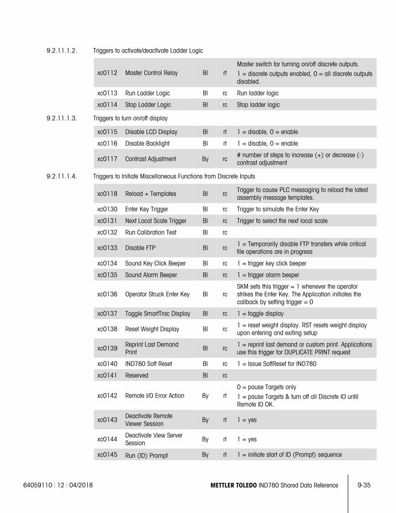
64059110 | 12 | 04/2018 METTLER TOLEDO IND780 Shared Data Reference 9-35
9.2.11.1.2. Triggers to activate/deactivate Ladder Logic
xc0112 Master Control Relay Bl rt Master switch for turning on/off discrete outputs.
1 = discrete outputs enabled, 0 = all discrete outputs disabled.
xc0113 Run Ladder Logic Bl rc Run ladder logic
xc0114 Stop Ladder Logic Bl rc Stop ladder logic
9.2.11.1.3. Triggers to turn on/off display
xc0115 Disable LCD Display Bl rt 1 = disable, 0 = enable
xc0116 Disable Backlight Bl rt 1 = disable, 0 = enable
xc0117 Contrast Adjustment By rc # number of steps to increase (+) or decrease (-) contrast adjustment
9.2.11.1.4. Triggers to Initiate Miscellaneous Functions from Discrete Inputs
xc0118 Reload + Templates Bl rc Trigger to cause PLC messaging to reload the latest assembly message templates.
xc0130 Enter Key Trigger Bl rc Trigger to simulate the Enter Key
xc0131 Next Local Scale Trigger Bl rc Trigger to select the next local scale
xc0132 Run Calibration Test Bl rc
xc0133 Disable FTP Bl rc 1 = Temporarily disable FTP transfers while critical file operations are in progress
xc0134 Sound Key Click Beeper Bl rc 1 = trigger key click beeper
xc0135 Sound Alarm Beeper Bl rc 1 = trigger alarm beeper
xc0136 Operator Struck Enter Key Bl rc SKM sets this trigger = 1 whenever the operator strikes the Enter Key. The Application initiates the callback by setting trigger = 0
xc0137 Toggle SmartTrac Display Bl rc 1 = toggle display
xc0138 Reset Weight Display Bl rc 1 = reset weight display. RST resets weight display upon entering and exiting setup
xc0139 Reprint Last Demand Print
Bl rc 1 = reprint last demand or custom print. Applications use this trigger for DUPLICATE PRINT request
xc0140 IND780 Soft Reset Bl rc 1 = Issue SoftReset for IND780
xc0141 Reserved Bl rc
xc0142 Remote I/O Error Action By rt 0 = pause Targets only
1 = pause Targets & turn off all Discrete IO until Remote IO OK.
xc0143 Deactivate Remote Viewer Session
By rt 1 = yes
xc0144 Deactivate View Server Session By rt 1 = yes
xc0145 Run (ID) Prompt By rt 1 = initiate start of ID (Prompt) sequence
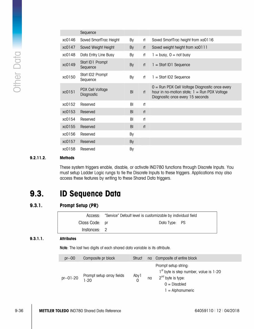
9-36 METTLER TOLEDO IND780 Shared Data Reference 64059110 | 12 | 04/2018
Oth
er D
ata
Sequence
xc0146 Saved SmartTrac Height By rt Saved SmartTrac height from xa0116
xc0147 Saved Weight Height By rt Saved weight height from xa0111
xc0148 Data Entry Line Busy By rt 1 = busy, 0 = not busy
xc0149 Start ID1 Prompt Sequence By rt 1 = Start ID1 Sequence
xc0150 Start ID2 Prompt Sequence
By rt 1 = Start ID2 Sequence
xc0151 PDX Cell Voltage Diagnostic
Bl rt 0 = Run PDX Cell Voltage Diagnostic once every hour in no-motion state; 1 = Run PDX Voltage Diagnostic once every 15 seconds
xc0152 Reserved Bl rt
xc0153 Reserved Bl rt
xc0154 Reserved Bl rt
xc0155 Reserved Bl rt
xc0156 Reserved By
xc0157 Reserved By
xc0158 Reserved By
9.2.11.2. Methods
These system triggers enable, disable, or activate IND780 functions through Discrete Inputs. You must setup Ladder Logic rungs to tie the Discrete Inputs to these triggers. Applications may also access these features by writing to these Shared Data triggers.
9.3. ID Sequence Data 9.3.1. Prompt Setup (PR)
Access: “Service” Default level is customizable by individual field
Class Code: pr Data Type: PS
Instances: 2
9.3.1.1. Attributes
Note: The last two digits of each shared data variable is its attribute.
pr--00 Composite pr block Struct na Composite of entire block
pr--01-20 Prompt setup array fields 1-20
Aby10 na
Prompt setup string:
1st byte is step number, value is 1-20
2nd byte is type:
0 = Disabled
1 = Alphanumeric
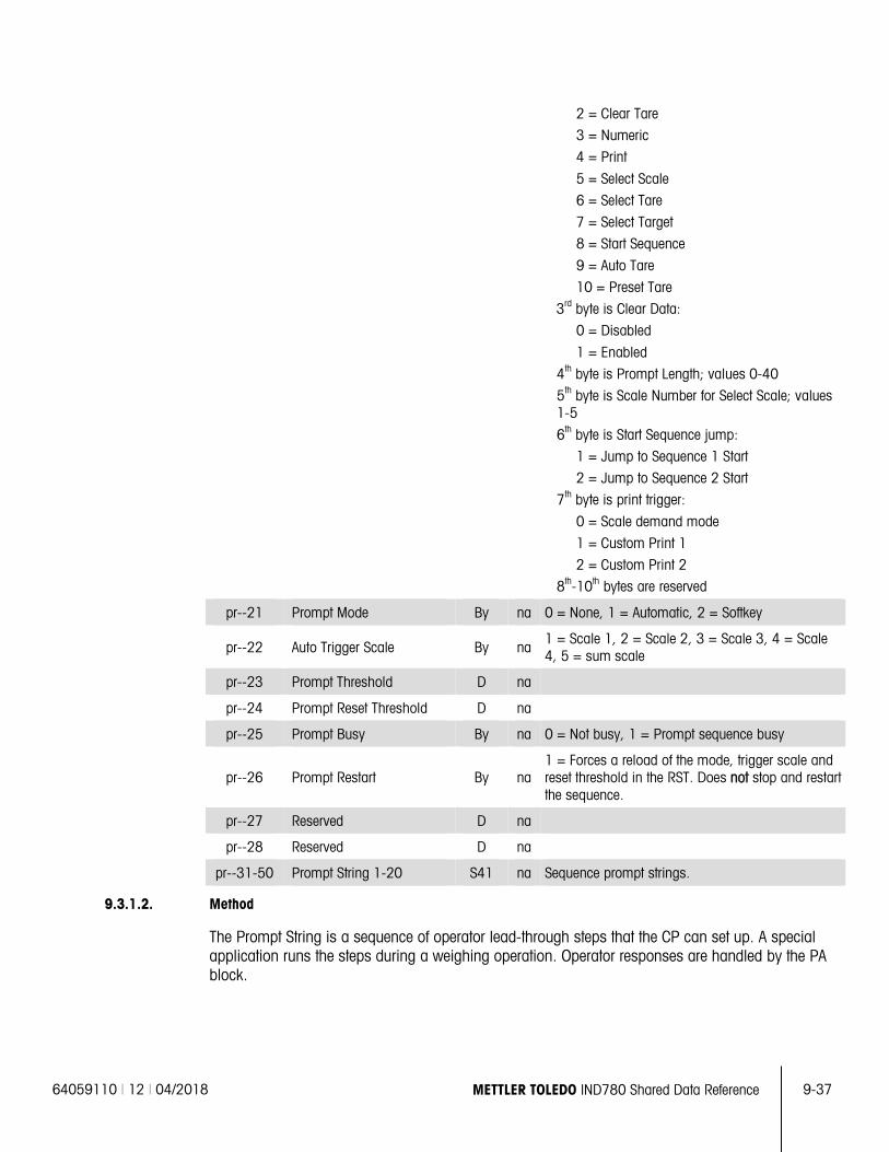
64059110 | 12 | 04/2018 METTLER TOLEDO IND780 Shared Data Reference 9-37
2 = Clear Tare
3 = Numeric
4 = Print
5 = Select Scale
6 = Select Tare
7 = Select Target
8 = Start Sequence
9 = Auto Tare
10 = Preset Tare
3rd byte is Clear Data:
0 = Disabled
1 = Enabled
4th byte is Prompt Length; values 0-40
5th byte is Scale Number for Select Scale; values 1-5
6th byte is Start Sequence jump:
1 = Jump to Sequence 1 Start
2 = Jump to Sequence 2 Start
7th byte is print trigger:
0 = Scale demand mode
1 = Custom Print 1
2 = Custom Print 2
8th-10th bytes are reserved
pr--21 Prompt Mode By na 0 = None, 1 = Automatic, 2 = Softkey
pr--22 Auto Trigger Scale By na 1 = Scale 1, 2 = Scale 2, 3 = Scale 3, 4 = Scale 4, 5 = sum scale
pr--23 Prompt Threshold D na
pr--24 Prompt Reset Threshold D na
pr--25 Prompt Busy By na 0 = Not busy, 1 = Prompt sequence busy
pr--26 Prompt Restart By na 1 = Forces a reload of the mode, trigger scale and reset threshold in the RST. Does not stop and restart the sequence.
pr--27 Reserved D na
pr--28 Reserved D na
pr--31-50 Prompt String 1-20 S41 na Sequence prompt strings.
9.3.1.2. Method
The Prompt String is a sequence of operator lead-through steps that the CP can set up. A special application runs the steps during a weighing operation. Operator responses are handled by the PA block.
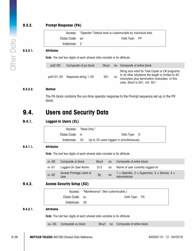
9-38 METTLER TOLEDO IND780 Shared Data Reference 64059110 | 12 | 04/2018
Oth
er D
ata
9.3.2. Prompt Response (PA)
Access: “Operator” Default level is customizable by individual field
Class Code: pa Data Type: PP
Instances: 2
9.3.2.1. Attributes
Note: The last two digits of each shared data variable is its attribute.
pa0100 Composite of pa block Struct na Composite of entire block
pa0101-20 Response string 1-20 S51 na
String size valid for Task Expert or C# programs. In all other situations the length is limited to 40 characters plus termination characters. In this case, Struct is S41, not S51.
9.3.2.2. Method
The PA block contains the run-time operator response to the Prompt sequence set up in the PR block.
9.4. Users and Security Data 9.4.1. Logged-In Users (XL)
Access: “Read Only.”
Class Code: xl Data Type: D
Instances: 25 Up to 25 users logged in simultaneously.
9.4.1.1. Attributes
Note: The last two digits of each shared data variable is its attribute.
xl--00 Composite xl block Struct na Composite of entire block
xl--01 Logged-On User Name S13 na Name of user currently logged-on
xl--02 Access Privilege Level of User By na
1 = Operator, 2 = Supervisor, 3 = Service, 4 = Administrator
9.4.2. Access Security Setup (XU)
Access: “Maintenance” (Not customizable.)
Class Code: xu Data Type: PS
Instances: 20
9.4.2.1. Attributes
Note: The last two digits of each shared data variable is its attribute.
xu--00 Composite xu block Struct na Composite of entire block
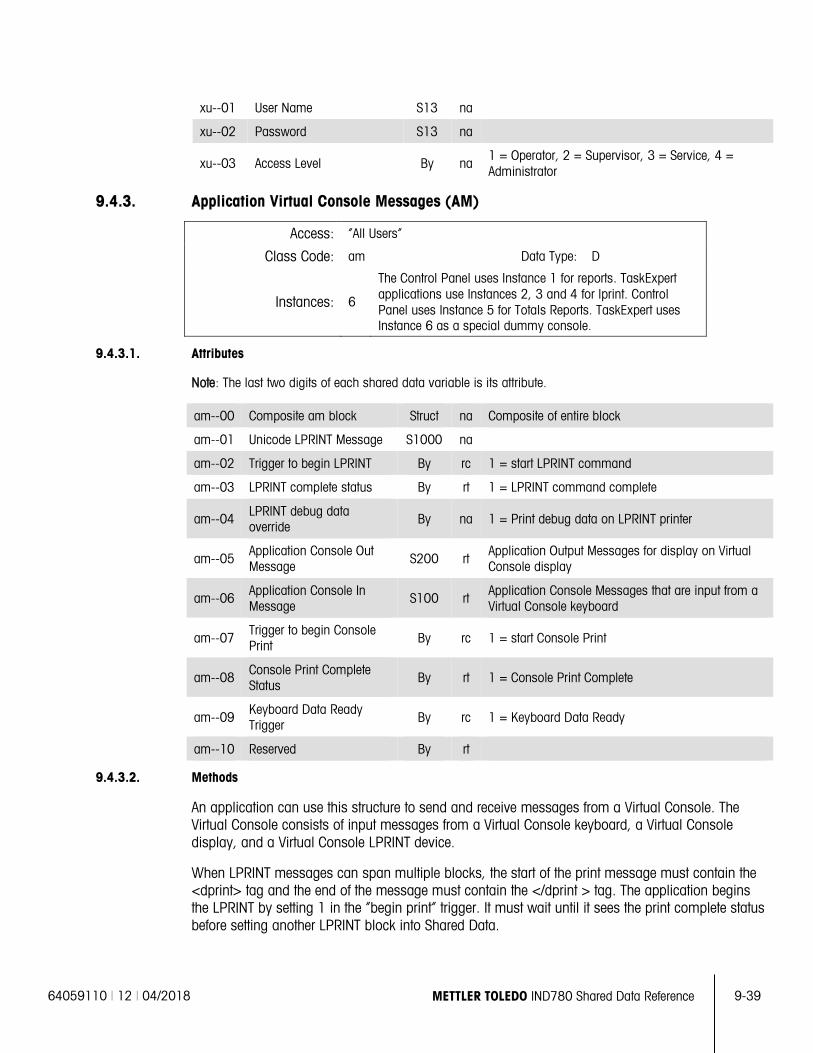
64059110 | 12 | 04/2018 METTLER TOLEDO IND780 Shared Data Reference 9-39
xu--01 User Name S13 na
xu--02 Password S13 na
xu--03 Access Level By na 1 = Operator, 2 = Supervisor, 3 = Service, 4 = Administrator
9.4.3. Application Virtual Console Messages (AM)
Access: “All Users”
Class Code: am Data Type: D
Instances: 6
The Control Panel uses Instance 1 for reports. TaskExpert applications use Instances 2, 3 and 4 for lprint. Control Panel uses Instance 5 for Totals Reports. TaskExpert uses Instance 6 as a special dummy console.
9.4.3.1. Attributes
Note: The last two digits of each shared data variable is its attribute.
am--00 Composite am block Struct na Composite of entire block
am--01 Unicode LPRINT Message S1000 na
am--02 Trigger to begin LPRINT By rc 1 = start LPRINT command
am--03 LPRINT complete status By rt 1 = LPRINT command complete
am--04 LPRINT debug data override
By na 1 = Print debug data on LPRINT printer
am--05 Application Console Out Message S200 rt
Application Output Messages for display on Virtual Console display
am--06 Application Console In Message
S100 rt Application Console Messages that are input from a Virtual Console keyboard
am--07 Trigger to begin Console Print By rc 1 = start Console Print
am--08 Console Print Complete Status
By rt 1 = Console Print Complete
am--09 Keyboard Data Ready Trigger By rc 1 = Keyboard Data Ready
am--10 Reserved By rt
9.4.3.2. Methods
An application can use this structure to send and receive messages from a Virtual Console. The Virtual Console consists of input messages from a Virtual Console keyboard, a Virtual Console display, and a Virtual Console LPRINT device.
When LPRINT messages can span multiple blocks, the start of the print message must contain the <dprint> tag and the end of the message must contain the </dprint > tag. The application begins the LPRINT by setting 1 in the “begin print” trigger. It must wait until it sees the print complete status before setting another LPRINT block into Shared Data.
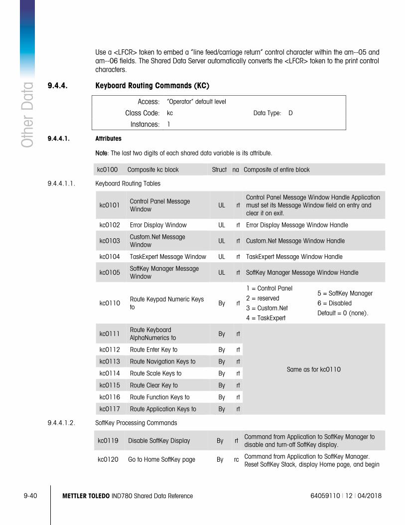
9-40 METTLER TOLEDO IND780 Shared Data Reference 64059110 | 12 | 04/2018
Oth
er D
ata
Use a <LFCR> token to embed a “line feed/carriage return” control character within the am--05 and am--06 fields. The Shared Data Server automatically converts the <LFCR> token to the print control characters.
9.4.4. Keyboard Routing Commands (KC)
Access: “Operator” default level
Class Code: kc Data Type: D
Instances: 1
9.4.4.1. Attributes
Note: The last two digits of each shared data variable is its attribute.
kc0100 Composite kc block Struct na Composite of entire block
9.4.4.1.1. Keyboard Routing Tables
kc0101 Control Panel Message Window
UL rt Control Panel Message Window Handle Application must set its Message Window field on entry and clear it on exit.
kc0102 Error Display Window UL rt Error Display Message Window Handle
kc0103 Custom.Net Message Window UL rt Custom.Net Message Window Handle
kc0104 TaskExpert Message Window UL rt TaskExpert Message Window Handle
kc0105 SoftKey Manager Message Window UL rt SoftKey Manager Message Window Handle
kc0110 Route Keypad Numeric Keys to By rt
1 = Control Panel
2 = reserved
3 = Custom.Net
4 = TaskExpert
5 = SoftKey Manager
6 = Disabled
Default = 0 (none).
kc0111 Route Keyboard AlphaNumerics to
By rt
Same as for kc0110
kc0112 Route Enter Key to By rt
kc0113 Route Navigation Keys to By rt
kc0114 Route Scale Keys to By rt
kc0115 Route Clear Key to By rt
kc0116 Route Function Keys to By rt
kc0117 Route Application Keys to By rt
9.4.4.1.2. SoftKey Processing Commands
kc0119 Disable SoftKey Display By rt Command from Application to SoftKey Manager to disable and turn-off SoftKey display.
kc0120 Go to Home SoftKey page By rc Command from Application to SoftKey Manager. Reset SoftKey Stack, display Home page, and begin
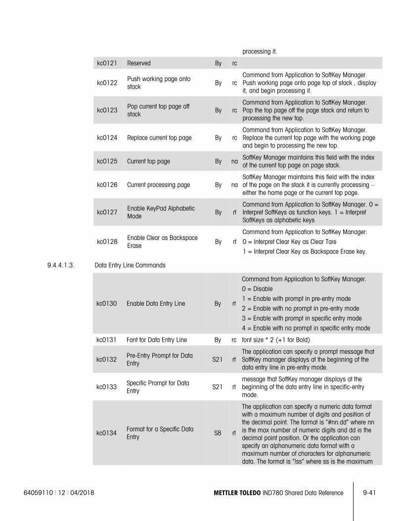
64059110 | 12 | 04/2018 METTLER TOLEDO IND780 Shared Data Reference 9-41
processing it.
kc0121 Reserved By rc
kc0122 Push working page onto stack By rc
Command from Application to SoftKey Manager. Push working page onto page top of stack , display it, and begin processing it.
kc0123 Pop current top page off stack
By rc Command from Application to SoftKey Manager. Pop the top page off the page stack and return to processing the new top.
kc0124 Replace current top page By rc Command from Application to SoftKey Manager. Replace the current top page with the working page and begin to processing the new top.
kc0125 Current top page By na SoftKey Manager maintains this field with the index of the current top page on page stack.
kc0126 Current processing page By na SoftKey Manager maintains this field with the index of the page on the stack it is currently processing – either the home page or the current top page.
kc0127 Enable KeyPad Alphabetic Mode
By rt Command from Application to SoftKey Manager. 0 = Interpret SoftKeys as function keys. 1 = Interpret SoftKeys as alphabetic keys
kc0128 Enable Clear as Backspace Erase
By rt
Command from Application to SoftKey Manager:
0 = Interpret Clear Key as Clear Tare
1 = Interpret Clear Key as Backspace Erase key.
9.4.4.1.3. Data Entry Line Commands
kc0130 Enable Data Entry Line By rt
Command from Application to SoftKey Manager.
0 = Disable
1 = Enable with prompt in pre-entry mode
2 = Enable with no prompt in pre-entry mode
3 = Enable with prompt in specific entry mode
4 = Enable with no prompt in specific entry mode
kc0131 Font for Data Entry Line By rc font size * 2 (+1 for Bold)
kc0132 Pre-Entry Prompt for Data Entry S21 rt
The application can specify a prompt message that SoftKey manager displays at the beginning of the data entry line in pre-entry mode.
kc0133 Specific Prompt for Data Entry
S21 rt message that SoftKey manager displays at the beginning of the data entry line in specific-entry mode.
kc0134 Format for a Specific Data Entry S8 rt
The application can specify a numeric data format with a maximum number of digits and position of the decimal point. The format is “#nn.dd” where nn is the max number of numeric digits and dd is the decimal point position. Or the application can specify an alphanumeric data format with a maximum number of characters for alphanumeric data. The format is “!ss” where ss is the maximum

9-42 METTLER TOLEDO IND780 Shared Data Reference 64059110 | 12 | 04/2018
Oth
er D
ata
number of alphanumeric characters.
kc0135 Format for Pre-Entry Data S8 rt
The application can specify a numeric data or alphanumeric data format for data the operator enters in “pre-entry” mode. The format is the same as kc0134.
kc0136 Data Entry Line Data S40 rt
The SoftKey Manager records data here that the operator entered on the data entry line. The last character of the buffer contains the termination character.
kc0137 Send Key Code to CP By rt
Send Key Code from TaskExpert to Control Panel, as follows:
1 = Select Scale
2 = Zero
3 = Tare
4 = Print
8 = Clear
11 = Enter Setup
kc0138 Reserved By rt
kc0139 Reserved S40 rt
kc0140 Reserved S40 rt
9.4.4.2. Method
The SoftKey Manager sends a custom message containing the SoftKeys to the Message Window of the appropriate application. Each application must write its Message Window handle to Shared Data in order to receive the messages. Before an application terminates, it must clear its Message Window handle.
Other fields are commands from the applications to the SoftKey Manager to control processing of the SoftKey pages.
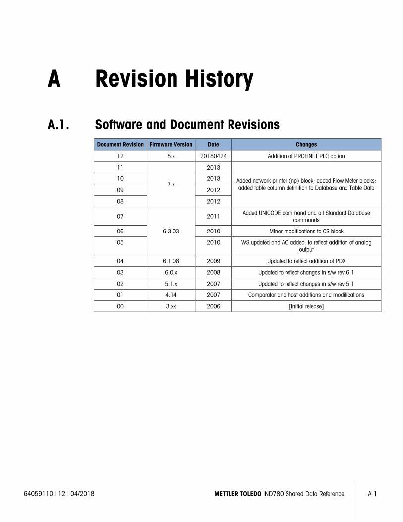
64059110 | 12 | 04/2018 METTLER TOLEDO IND780 Shared Data Reference
A-1
A Revision History
A.1. Software and Document Revisions Document Revision Firmware Version Date Changes
12 8.x 20180424 Addition of PROFINET PLC option
11
7.x
2013
Added network printer (np) block; added Flow Meter blocks; added table column definition to Database and Table Data
10 2013
09 2012
08 2012
07
6.3.03
2011 Added UNICODE command and all Standard Database commands
06 2010 Minor modifications to CS block
05 2010 WS updated and AO added, to reflect addition of analog output
04 6.1.08 2009 Updated to reflect addition of PDX
03 6.0.x 2008 Updated to reflect changes in s/w rev 6.1
02 5.1.x 2007 Updated to reflect changes in s/w rev 5.1
01 4.14 2007 Comparator and host additions and modifications
00 3.xx 2006 [Initial release]
To protect your METTLER TOLEDO product’s future:
Congratulations on choosing the quality and precision of METTLER TOLEDO. Proper use according to these instructions and regular calibration and maintenance by our factory-trained service team ensure dependable and accurate operation, protecting your investment. Contact us about a METTLER TOLEDO service agreement tailored to your needs and budget.
We invite you to register your product at www.mt.com/productregistration so we can contact you about enhancements, updates and important notifications concerning your product.
www.mt.com/IND780 For more information
Mettler-Toledo, LLC 1900 Polaris Parkway Columbus, OH 43240
© 2018 Mettler-Toledo, LLC 64059110 Rev. 12, 04/2018