IND360legacy User's Guide Weighing Terminal
35
User's Guide IND360legacy Weighing Terminal
Transcript of IND360legacy User's Guide Weighing Terminal

User
's G
uide
IND360legacy Weighing Terminal
IND360legacy Weighing Terminal
Essential Services for Dependable Performance of Your IND360legacy Weighing Terminal
Congratulations on choosing the quality and precision of METTLER TOLEDO. Proper use of your new equipment according to this Manual and regular calibration and maintenance by our factory-trained service team ensures dependable and accurate operation, protecting your investment. Contact us about a service agreement tailored to your needs and budget. Further information is available at www.mt.com/service.
There are several important ways to ensure you maximize the performance of your investment:
1. Register your product: We invite you to register your product at www.mt.com/productregistration so we can contact you about enhancements, updates and important notifications concerning your product.
2. Contact METTLER TOLEDO for service: The value of a measurement is proportional to its accuracy – an out of specification scale can diminish quality, reduce profits and increase liability. Timely service from METTLER TOLEDO will ensure accuracy and optimize uptime and equipment life.
a. Installation, Configuration, Integration and Training: Our service representatives are factory-trained, weighing equipment experts. We make certain that your weighing equipment is ready for production in a cost effective and timely fashion and that personnel are trained for success.
b. Initial Calibration Documentation: The installation environment and application requirements are unique for every industrial scale so performance must be tested and certified. Our calibration services and certificates document accuracy to ensure production quality and provide a quality system record of performance.
c. Periodic Calibration Maintenance: A Calibration Service Agreement provides on-going confidence in your weighing process and documentation of compliance with requirements. We offer a variety of service plans that are scheduled to meet your needs and designed to fit your budget.
d. GWP® Verification: A risk-based approach for managing weighing equipment allows for control and improvement of the entire measuring process, which ensures reproducible product quality and minimizes process costs. GWP (Good Weighing Practice), the science-based standard for efficient life-cycle management of weighing equipment, gives clear answers about how to specify, calibrate and ensure accuracy of weighing equipment, independent of make or brand.

© METTLER TOLEDO 2021
No part of this manual may be reproduced or transmitted in any form or by any means, electronic or mechanical, including photocopying and recording, for any purpose without the express written permission of METTLER TOLEDO.
U.S. Government Restricted Rights: This documentation is furnished with Restricted Rights.
Copyright 2021 METTLER TOLEDO. This documentation contains proprietary information of METTLER TOLEDO. It may not be copied in whole or in part without the express written consent of METTLER TOLEDO.
COPYRIGHT METTLER TOLEDO® is a registered trademark of Mettler-Toledo, LLC. All other brand or product names are trademarks or registered trademarks of their respective companies.
METTLER TOLEDO RESERVES THE RIGHT TO MAKE REFINEMENTS OR CHANGES WITHOUT NOTICE.
FCC Notice This device complies with Part 15 of the FCC Rules and the Radio Interference Requirements of the Canadian Department of Communications. Operation is subject to the following conditions: (1) this device may not cause harmful interference, and (2) this device must accept any interference received, including interference that may cause undesired operation.
This equipment has been tested and found to comply with the limits for a Class A digital device, pursuant to Part 15 of FCC Rules. These limits are designed to provide reasonable protection against harmful interference when the equipment is operated in a commercial environment. This equipment generates, uses, and can radiate radio frequency energy and, if not installed and used in accordance with the instruction manual, may cause harmful interference to radio communications. Operation of this equipment in a residential area is likely to cause harmful interference in which case the user will be required to correct the interference at his or her expense.
Declaration of Conformity is available at http://glo.mt.com/global/en/home/search/compliance.html/compliance/.

Warnings and Cautions • READ this manual BEFORE operating or servicing this equipment and FOLLOW these instructions carefully.
• SAVE this manual for future reference.
CAUTION THE IND360 IS INTENDED TO BE USED FOR PROCESS CONTROL AND IS NOT APPROVED AS A SAFETY COMPONENT. WHEN USED AS A COMPONENT PART OF A SYSTEM, ANY SAFETY CIRCUITS MUST BE INDEPENDENT OF THE IND360 AND REMOVE POWER FROM THE IND360 OUTPUTS IN THE EVENT OF AN EMERGENCY STOP OR EMERGENCY POWER DOWN.
CAUTION
THE IND360 IS NOT INTRINSICALLY SAFE! DO NOT USE IN HAZARDOUS AREAS CLASSIFIED AS DIVISION 1, ZONE 0, ZONE 20, ZONE 1 OR ZONE 21 BECAUSE OF COMBUSTIBLE OR EXPLOSIVE ATMOSPHERES. FAILURE TO COMPLY WITH THIS WARNING COULD RESULT IN BODILY HARM AND/OR PROPERTY DAMAGE.
CAUTION
IND360 MUST NOT BE INSTALLED INTO A DIVISION 2 OR ZONE 2/22 ENVIRONMENT.
CAUTION
DO NOT ACTIVATE POWER OVER ETHERNET (PoE) ON ETHERNET SWITCHES ON THE IND360 NETWORK. ACTIVATING PoE MAY RESULT IN DAMAGE TO THE IND360.
WARNING WHEN THIS EQUIPMENT IS INCLUDED AS A COMPONENT PART OF A SYSTEM, THE RESULTING DESIGN MUST BE REVIEWED BY QUALIFIED PERSONNEL WHO ARE FAMILIAR WITH THE CONSTRUCTION AND OPERATION OF ALL COMPONENTS IN THE SYSTEM AND THE POTENTIAL HAZARDS INVOLVED. FAILURE TO OBSERVE THIS PRECAUTION COULD RESULT IN BODILY HARM AND/OR PROPERTY DAMAGE.
CAUTION
DO NOT INSTALL, DISCONNECT OR PERFORM ANY SERVICE ON THIS EQUIPMENT BEFORE POWER HAS BEEN SWITCHED OFF AND THE AREA HAS BEEN SECURED AS NON-HAZARDOUS BY PERSONNEL AUTHORIZED TO DO SO BY THE RESPONSIBLE PERSON ON-SITE.
WARNING ONLY THE COMPONENTS SPECIFIED ON THE IND360 DOCUMENTATION CAN BE USED IN THIS TERMINAL. ALL EQUIPMENT MUST BE INSTALLED IN ACCORDANCE WITH THE INSTALLATION INSTRUCTIONS DETAILED IN THE INSTALLATION MANUAL. INCORRECT OR SUBSTITUTE COMPONENTS AND/OR DEVIATION FROM THESE INSTRUCTIONS CAN IMPAIR THE SAFETY OF THE TERMINAL AND COULD RESULT IN BODILY HARM AND/OR PROPERTY DAMAGE.
WARNING BEFORE CONNECTING/DISCONNECTING ANY INTERNAL ELECTRONIC COMPONENTS OR INTERCONNECTING WIRING BETWEEN ELECTRONIC EQUIPMENT ALWAYS REMOVE POWER AND WAIT AT LEAST THIRTY (30) SECONDS BEFORE ANY CONNECTIONS OR DISCONNECTIONS ARE MADE. FAILURE TO OBSERVE THESE PRECAUTIONS COULD RESULT IN DAMAGE TO OR DESTRUCTION OF THE EQUIPMENT AND/OR BODILY HARM.

W
arni
ngs
and
Caut
ions
CAUTION
ONLY PERMIT QUALIFIED PERSONNEL TO SERVICE THE TERMINAL. EXERCISE CARE WHEN MAKING CHECKS, TESTS AND ADJUSTMENTS THAT MUST BE MADE WITH POWER ON. FAILING TO OBSERVE THESE PRECAUTIONS CAN RESULT IN BODILY HARM AND/OR PROPERTY DAMAGE.
NOTICE OBSERVE PRECAUTIONS FOR HANDLING ELECTROSTATIC SENSITIVE DEVICES.
Disposal of Electrical and Electronic Equipment
In conformance with the European Directive 2012/19/EC on Waste Electrical and Electronic Equipment (WEEE) this device may not be disposed of in domestic waste. This also applies to countries outside the EU, per their specific requirements.
Please dispose of this product in accordance with local regulations at the collecting point specified for electrical and electronic equipment.
If you have any questions, please contact the responsible authority or the distributor from which you purchased this device.
Should this device be passed on to other parties (for private or professional use), the content of this regulation must also be related.
Thank you for your contribution to environmental protection.

30705926 | 00 | 08/2021 METTLER TOLEDO IND360legacy Weighing Terminal User's Guide 1
Contents 1 Introduction ................................................................................. 1-1
1.1. Special Notes on Migration ............................................................. 1-1
1.2. IND360legacy Overview ................................................................ 1-2
1.6. Model Identification ....................................................................... 1-3
3 Configuration .............................................................................. 3-1
3.6. Application ................................................................................... 3-1 3.6.2. Comparators ....................................................................................................... 3-1 3.6.3. Discrete I/O ......................................................................................................... 3-1
3.8. Communication ............................................................................ 3-2 3.8.3. EtherNet/IP .......................................................................................................... 3-2 3.8.4. Profibus DP ........................................................................................................ 3-3 3.8.5. PROFINET ........................................................................................................... 3-4 3.8.7. ModBus RTU ....................................................................................................... 3-5
B. Default Settings ........................................................................... B-1
B.1. Default Parameter Settings ............................................................. B-1
C TCP/IP Communication................................................................. C-1
C.2. MT-SICS Commands ..................................................................... C-1
E. IND360legacy PLC Interface ......................................................... E-1
E.1. ModBus RTU ................................................................................ E-1 E.1.1. Data Definition .................................................................................................... E-1
E.2. EtherNet/IP ................................................................................... E-8
E.3. Data Definition .............................................................................. E-8 E.3.1. Data Formats ...................................................................................................... E-8 E.3.2. Message Size...................................................................................................... E-8 E.3.3. Byte Order ........................................................................................................ E-10 E.3.4. Data Integrity .................................................................................................... E-10 E.3.5. Format Details................................................................................................... E-11 E.3.6. Controlling the Discrete I/O Using a PLC Interface .................................................. E-18

30705926 | 00 | 08/2021 METTLER TOLEDO IND360legacy User's Guide 1-1
1 Introduction This manual details the difference in settings and functionality between the IND360base and the IND360legacy weighing terminal. Only areas of difference are covered. To simplify comparison between the IND360legacy and the IND360, this manual’s chapter and section structures parallel those of the base IND360 User’s Guide.
The IND360legacy provides much of the functionality of the IND131/IND331 weighing terminals to offer backward compatibility. It is designed to support a seamless transition to next-generation indicators without the need to change the PLC programming.
Features include:
• Large color operator display and network status LEDs.
• Web interface for service and monitoring.
• Integrated logging of errors and configuration changes.
• Backup, restore and cloning of device configuration through web interface.
1.1. Special Notes on Migration The IND360legacy is mechanically compatible with IND131/331. There is no need to drill new holes into the control cabinet in order to mount the larger IND360 display.
Compared to IND131/331, the following functionality has been replaced by other solutions in IND360:
• SD card (Replaced by a web interface)
• MT-SICS serial command interface (Now supported by IND360base)
• Legacy filling application (Now supported by IND360fill/dose)
The following functionality previously supported by IND131/331 is not supported by IND360:
• Connectivity to ModBus TCP (available beginning 2022)
• Connectivity to DeviceNet, ControlNet and CCLink
• Serial port printers
• While solid state digital inputs are supported by IND360legacy, the dry contact relay option is no longer supported.
For new applications and setups, the IND360base or an IND360 with an application are better choices. This new generation of indicator offers high-speed communication, integration within minutes, and connectivity to smart sensors.

1-2 METTLER TOLEDO IND360legacy User's Guide 30705926 | 00 | 08/2021
Intro
duct
ion
1.2. IND360legacy Overview IND360legacy Features
• Scale connection:
o Single analog load cell scale base
o A network of up to 8 350Ω or 20 1kΩ analog load cells
o Not supported: smart sensors like POWERCELL and Precision
• Supported languages: English, Chinese.
• Network and system status LEDs (Red, Orange, Green)
• Legal for Trade lockout switch
• Weighing functions e.g. zero, tare, clear
• Web interface for parameter configuration
• OLED (DIN version) or TFT (Panel/Harsh version) display for easy local configuration
• 3-level user security
• Real-time clock with battery backup
• CalFree™ Adjustment of strain gauge scales without test weights
• Comparison with IND131/IND331-specific functionality:
o Connectivity to PROFINET, Profibus DP, EtherNet/IP and ModBus RTU automation buses using the IND131/IND331 protocols and their device description files. Device description files are not certified in combination with the IND360legacy device.
o Acyclic communication is not available for EtherNet/IP or Profinet.
o Up to 3 comparators can be defined.*
o 4-20 mA analog output and digital I/O options are available.*
* Rate and Absolute rate are not supported.
30705926 | 00 | 08/2021 METTLER TOLEDO IND360legacy User's Guide 1-3
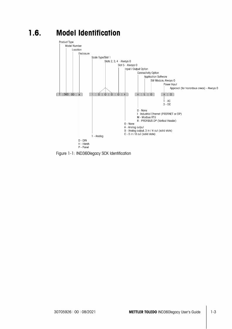
1.6. Model Identification
Figure 1-1: IND360legacy SCK Identification

30705926 | 00 | 08/2021 METTLER TOLEDO IND360legacy User's Guide 3-1
3 Configuration
3.6. Application 3.6.2. Comparators
The IND360legacy supports up to three comparators. Comparator setup is the same as for the IND360base.
3.6.3. Discrete I/O
3.6.3.1. Discrete Inputs
The Discrete I/O option is configured as it is in the IND360base, but includes different options. Available input options are indicated in Table 3-1.
Table 3-1: Discreet I/O Inputs
Index Function Function description Trigger
1 None None NA
2 Clear Tare Clear Tare Pulse
4 Keypad Disable On main screen, pressing the keys has no effect1
Level
5 Silence Alarm Silence Alarm on DIO output. Level
6 Tare Tare Pulse
7 Zero Zero Pulse
1 When Keypad Disable is activated while in the Configuration menu, this setting becomes active once the operator returns to the main screen.
3.6.3.2. Discrete Outputs
Available output options are indicated in Table 3-2
Table 3-2: Discreet I/O Outputs
Function Function description
None No output
Center of Zero Indicates that the scale is at the center of calibrated zero
Comparators 1 to 3 Sends results of the comparator’s calculation
Alarm Triggers alarm
Motion Indicates that the scale has met the criterion for motion
Net Sends current net weight

3-2 METTLER TOLEDO IND360legacy User's Guide 30705926 | 00 | 08/2021
Conf
igur
atio
n Function Function description
Over Capacity Indicates that the scale is above its calibrated capacity
Under Zero Indicates that the scale output is below calibrated zero
3.8. Communication The IND360legacy uses the same device description files as the IND131/IND331, but in this application the combination of device and files is not certified. The data format is backward compatible.
3.8.3. EtherNet/IP
Figure 3-1: Web Interface EtherNet/IP Screen
EtherNet/IP setup differs from the IND360base in two parameters: Format, and Used Port.
3.8.3.1. Format EtherNet/IP
Three data formats are available:
Integer [default], Divisions, Floating Point
Integer Reports scale weight as a signed 16 bit integer (+/- 32767)
Division Reports scale weight in display divisions (+/-32767). The PLC multiplies the reported divisions by the increment size to calculate the weight in display units.

30705926 | 00 | 08/2021 METTLER TOLEDO IND360legacy User's Guide 3-3
Floating Point Displays weight in floating point data format.
3.8.3.2. Byte Order
Choices are:
Big Endian, Little Endian, Word Swap, Byte Swap [default]
3.8.3.3. Used Port
This parameter determines which data format to use. Options are:
1-Port Use the data format of the IND131/IND331 with 1 Ethernet port [default]
2-Port Use the data format of the IND131/IND331 with 2 Ethernet ports
3.8.4. Profibus DP
Figure 3-2: Web Interface PROFIBUS DP Screen
3.8.4.1. Format PROFIBUS
Three data formats are available:
Integer [default], Divisions, Floating Point
Integer Reports scale weight as a signed 16 bit integer (+/- 32767)
Division Reports scale weight in display divisions (+/-32767). The PLC multiplies the reported divisions by the increment size to calculate the weight in display units.
Floating Point Displays weight in floating point data format.
3.8.4.2. Byte Order
This parameter selects the order in which the data bytes and words will be presented in the PLC data format. The choices are:
Byte Swap [Default], Standard, Word Swap, Double Word Swap.
Word Swap Takes the IEE 754 single-precision floating point format and swaps the two words in the 32-bit double word. This format is compatible with RSLogix 5000 processors.

3-4 METTLER TOLEDO IND360legacy User's Guide 30705926 | 00 | 08/2021
Conf
igur
atio
n Byte Swap Makes the floating point format compatible with S7 PROFIBUS.
Double Word Swap
Makes the data format compatible with the Modicon Quantum PLC for Modbus TCP networks.
Standard Makes the data format compatible with PLC5.
3.8.5. PROFINET
Figure 3-3: PROFINET Screen
3.8.5.1. Format Profinet
Three data formats are available:
Integer [default], Divisions, Floating Point
Integer Reports scale weight as a signed 16 bit integer (+/- 32767)
Division Reports scale weight in display divisions (+/-32767). The PLC multiplies the reported divisions by the increment size to calculate the weight in display units.
Floating Point Displays weight in floating point data format.
3.8.5.2. Byte Order
Choices are:
Big Endian, Little Endian, Word Swap, Byte Swap [default]

30705926 | 00 | 08/2021 METTLER TOLEDO IND360legacy User's Guide 3-5
3.8.7. ModBus RTU
Figure 3-4: ModBus RTU Screen
Integer ModBus RTU reports scale weight as a signed 16-bit integer (±32767)
Division ModBus RTU reports scale weight in display divisions (±32767). To calculate the weight in display units, the PLC must multiply the reported number of divisions by the increment size.
3.8.7.1. Byte Order
Byte order is set fixed to Word Swap.

30705926 | 00 | 08/2021 METTLER TOLEDO IND360legacy User's Guide B-1
B. Default Settings
B.1. Default Parameter Settings Table B-1: Default Parameter Settings – Application
Setup Feature Default Value
Application – DIO Inputs 1 and 2
Trigger mode +True
Assignment None
Application – DIO Outputs 1, 2, 3 and 4
Assignment None
Application – Comparators 1, 2 and 3
Source None
Description [Blank]
Table B-2: Default Parameter Settings – Communication
Setup Feature Default Value
Communication – EtherNet/IP
Format Integer
Byte order Byte Swap
Used port 1-Port
Communication – Profibus DP
Format Integer
Byte order Byte Swap
Communication – Profinet
Format Integer
Byte order Byte Swap
Communication – Modbus RTU
Format Integer

30705926 | 00 | 08/2021 METTLER TOLEDO IND360legacy User's Guide C-1
C TCP/IP Communication
C.2. MT-SICS Commands The IND360legacy does not support MT-SICS commands. These are available in the IND360base.

30705926 | 00 | 08/2021 METTLER TOLEDO IND360legacy User's Guide E-1
E. IND360legacy PLC Interface
E.1. ModBus RTU Only ModBus RTU commands 03H and 06H are supported by the IND360legacy. The master reads data from the IND360legacy registers 40001 through 40011 using the Read Holding Register command 03H. The master writes data to the individual IND360legacy registers using the Write Single Register command 06H.
The IND360legacy data contains numerical and status information and commands. The numerical data sent to and from the terminal is available in either Integer or Division format. Only one data format can be set up and used at one time by the IND360legacy; the format is selected in setup.
In Integer mode, IND360legacy reports scale weight as a signed 16-bit integer (±32767)
In Divisions mode, IND360legacy reports scale weight in display divisions (±32767). To calculate the weight in display units, the PLC must multiply the reported number of divisions by the increment size.
E.1.1. Data Definition
E.1.1.1. Holding Registers 40001 thru 40011 Assignments
Table E-1 shows the holding register assignment. Note that the register addresses are PLC-dependent. Table E-1 shows the register addresses as 5 digits. If the register addressing is 4 digits, the address range would be 4001 thru 4011. If the register addressing is 6 digits, the address range is 400001 thru 400011. The addressing is based on the type of PLC used. In any case, the IND360legacy registers are mapped to the first 28 holding registers.
Table E-1: Modbus RTU Holding Register Assignment (Integer and Division)
Register Address Read/Write Description
40001 R Displayed weight
40002 R Tare weight
40003 R Data available here is selected by setting bits Select 1, Select 2 and Select 3 at address 40006 (refer to Table E-4)
40004 R Scale status bits
40005 R/W Write weight or value
40006 R/W Write command
40007 R/W Write Variable Selection
40008 R/W Write Value (selected by 40007)
40009 R/W Write Read Value Selection

E-2 METTLER TOLEDO IND360legacy User's Guide 30705926 | 00 | 08/2021
IND
360l
egac
y PL
C In
terfa
ce
Register Address Read/Write Description
40010 R Read Value (selected by 40009)
40011 R Read Value selection
40012 40013
R Display Weight in Integer or Division, Long Type
40014 R Scale status bits, same as register 40004
40015 40016 R Tare weight in Integer or Division, Long Type
40017 40018 R Gross Weight in Integer or Division, Long Type
40019 40020 R Display Weight (Floating point value)
40021 40022 R Tare Weight (Floating point value)
40023 40024 R Gross Weight (Floating point value)
40025 40026 R/W Write Value (selected by 40007), Long Type
40027 40028 R Read Value (selected by 40009), Long Type
E.1.1.1.1. Address 40001
Displayed Weight is read from address 40001.
E.1.1.1.2. Address 40002
Tare Weight is read from address 40002.
E.1.1.1.3. Address 40003
Data read from address 40003 can represent gross weight, net weight or tare weight.
The type of data to be read from register 40003 is selected by the Select 1, Select 2 and Select 3 bits in command register 40006. See Table E-4 for the definition of these bits.
E.1.1.1.4. Address 40004
Address 40004 contains bit encoded status information. Table E-2 shows the function of each bit.
Table E-2: Address 40004 Bit Functions
Bit number Function
0 Not Used
1 Not Used
2 Not Used
3 Not Used
4 Not Used
5 Comparator 31

30705926 | 00 | 08/2021 METTLER TOLEDO IND360legacy User's Guide E-3
Bit number Function
6 Comparator 21
7 Comparator 11
8 Not Used
9 Input 12
10 Input 22
11 Input 3
12 Motion3
13 Net Mode4
14 Not Used
15 Data OK6
Notes for Table E-2
1 Bits 5, 6, and 7 indicate the state of the associated comparator logic; when the bit is set to ‘1’ the comparator state is ‘ON’; when the bit is set to ‘0’ the comparator state is ‘OFF’. The setup of each comparator will determine when the state is ‘ON’ or ‘OFF’.
2 Bits 9, 10, 11 indicate the state of the associated hardware discrete input in the terminal; these are Input 1 and Input 2. When the input is ‘ON” the associated bit is set to ‘1’.
3 Bit 12; The motion bit is set to ‘1’ when the scale is in motion (unstable).
4 Bit 13; The net mode bit is set to ‘1’ when scale is in the net mode (a tare has been taken). When the scale is in the gross mode, the bit will be ‘0’.
6 Bit 15; The data ok bit is set to ‘1’ when the terminal operating conditions are normal. The bit is set to ‘0’ during power-up, during terminal setup, when the scale is over capacity or under zero, and when in the x10 display mode; additionally, the first word integer value is set to ‘0’. The PLC should continuously monitor the data ok bit to determine the validity of the data in the PLC.
E.1.1.1.5. Address 40005
The master writes values to this address. The value (in integer or division format) represents data that is to be written to the IND360legacy memory (e.g. preset tare). Bits in address 40006 set the data type and indicate to the terminal which field is being sent.
It is important that the data is first written to address 40005 and then the respective bit is set in address 40006.
As an example: To send a preset tare value of 123 to the IND360legacy the master would first write 123 to address 40005 and then set the Preset Tare bit (Bit 3) in address 40006 to a “1”. (Refer to Table E-3).
E.1.1.1.6. Address 40006
The master writes discrete commands to the IND360legacy via address 40006. The commands are shown in Table E-3.

E-4 METTLER TOLEDO IND360legacy User's Guide 30705926 | 00 | 08/2021
IND
360l
egac
y PL
C In
terfa
ce
Table E-3: Address 40006 Functions
Bit number Function [Scale Command]
0 Select 11
1 Select 21
2 Select 31
3 Load Preset Tare2
4 Clear Tare3
5 Tare4
6 Print5
7 Zero6
8 Not Used
9 Not Used
10 Not Used
11 Not Used
12 Output 111
13 Output 211
14 Output 311
15 Not Used
Notes for Table E-3
1 Bits 0, 1 and 2 change the data being sent from the terminal in Address 40003. Use a decimal value in binary format within bits 0, 1, and 2 to change the data reported by the terminal. Use these bits to verify that the values sent to the IND360legacy are correct. Refer to Table E-4 for details of the bits.
Table E-4: Select 1, 2 and 3
Select 3 Select 2 Select 1
0 0 0 Gross weight
0 0 1 Net weight
0 1 0 Tare weight
0 1 1
1 0 0
1 0 1
1 1 0
1 1 1 Gross weight
2 Bit 3 - A transition from ‘0’ to ‘1’ will cause the value in address 40005 to be loaded into the tare register of the terminal and set the terminal into the net mode. Set this bit to ‘1’ only after address 40005 has been loaded with the required value.

30705926 | 00 | 08/2021 METTLER TOLEDO IND360legacy User's Guide E-5
3 Bit 4 - A transition from ‘0’ to ‘1’ will cause the terminal tare register to be set to ‘0’ and the terminal will be set to the gross weight mode.
4 Bit 5 - A transition from ‘0’ to ‘1’ will cause the weight on the scale to be used as the tare value and set the terminal to the net mode (equivalent to a tare command). The scale will not tare while motion is detected. If the scale does not tare within 3 seconds the command must be resent.
5 Bit 6 - A transition from ‘0’ to ‘1’ will issue a print command.
6 Bit 7 - A transition from ‘0’ to ‘1’ will cause the scale to re-zero, but only within the ranges established in scale setup.
11 Bits 12, 13 and 14 will cause the associated hardware discrete output to be turned ‘ON’ and ‘OFF’. Setting a bit to ‘1’ will cause the output to turn ‘ON’; setting the bit to ‘0’ will cause the output to turn ‘OFF’. The PLC control will not override the status of the outputs if they are being used by the terminal logic as programmed in setup of the terminal. Leave the outputs assigned as None in setup to allow the PLC to have control.
E.1.1.1.7. Address 40007
The master writes calibration commands to address 40007. The master must send a Clear Command (“0”) before each Calibrate Command is sent. The IND360legacy is waiting for the command to go to “0” before another command is acknowledged. The read values and write values for address 40007 do not coincide. The commands are listed in Table E-5.
Table E-5: Calibration Commands
Command Function
0 Clear Command Register
40 (dec) Calibrate Zero
41 (dec) Calibrate Span #1
42 (dec) Calibrate Span #2
602 (dec) Load Span #1 weight from address 40008
604 (dec) Load Span #2 weight from address 40008
E.1.1.1.8. Address 40008
The master writes values to address 40008. Commands in address 40007 load the value from address 40008 to the appropriate IND360legacy calibration register.
E.1.1.1.9. Address 40009
The master writes command values to address 40009 to read various calibration parameters including the status and test weight values. The requested data is reported in address 40010.
Table E-6: Report Calibration Information Command
Command Function
26 (dec) Calibration Status Request
602 (dec) Report Test Weight #1
604 (dec) Report Test Weight #2

E-6 METTLER TOLEDO IND360legacy User's Guide 30705926 | 00 | 08/2021
IND
360l
egac
y PL
C In
terfa
ce
E.1.1.1.10. Address 40010
Address 40010 reports either the status of the calibration or the calibration test weight values depending upon what command has been written to address 40009 and address 40011. Details are given in Table E-7.
Table E-7: Calibration Information
Report Calibration Info Command (Address 40009)
Response in Address 40010
26 (dec) 0 – Adjustment OK 1 – Adjustment in progress 10 (dec) – Adjusting dynamically 255 (dec) – Adjustment failure
602 (dec) Test Weight #1 value (if the value in address 40011 is equal to 602 (dec).
604 (dec) Test Weight #2 value (if the value in address 40011 is equal to 604 (dec).
E.1.1.1.11. Address 40011
Address 40011 reports test weight #1 and #2.
To read test weight #1 from the IND360legacy:
• The master writes 602(dec) to 40009.
• Read 40011, if 40011 is equal to 602(dec), 40010 is reporting test weight #1.
To read test weight #2 from the IND360legacy:
• The master writes 604(dec) to 40009.
• Read 40011, if 40011 equals to 604, 40010 will report test weight #2.
E.1.1.1.12. Addresses 40012 to 40028
This address range is for 32-bit (Long Type) data access instead of 16 bit. The commands (except for register 40014, which is a copy of 40004) occupy two registers instead of one.
These commands use two registers, and the ‘Long Type’ is 32 bit rather than 16 bit.
E.1.1.2. Calibrating the Scale via Modbus RTU
The IND360legacy can be calibrated via the Modbus RTU interface. The terminal supports 2-point (linearity disabled) and 3-point (linearity enabled) calibration.
E.1.1.2.1. Zero Adjustment
1. Clear 40007
2. Write 026 (dec) to 40009 to read the calibration status, the calibration status will be reported in 40010 as follows:
0 – adjustment OK
1– adjustment in progress

30705926 | 00 | 08/2021 METTLER TOLEDO IND360legacy User's Guide E-7
10 (dec) – adjust in dynamic
255 (dec) – adjustment failure
3. Write 1 to 40008
4. Write 40 (dec) to 40007 to trigger zero adjustment
E.1.1.2.2. Span #1 Calibration
1. Clear 40007.
2. Write test weight #1(Integer or Division format) to 40008.
3. Write 602(dec) to 40007. This is the trigger to write the value in 40008 to the IND360legacy SPAN #1 test weight register.
4. Clear 40007.
5. Write 026 (dec) to 40009 to read calibration status, the calibration status will be reported in 40010
6. Write 1 to 40008.
7. Write 41 (dec) to 40007. This writes the value in address 40008 to the IND360legacy start SPAN 1# adjustment trigger.
E.1.1.2.3. Span #2 Calibration
1. Clear 40007.
2. Write test weight #2 (Integer or Division format) to 40008.
3. Write 604 (dec) to 40007. This is the trigger to write the value in 40008 to SPAN #2 test weight.
4. Clear 40007.
5. Write 026 to 40009 to read the calibration status.
6. Write 1 to 40008.
7. Write 42 to 40007. This writes the value in address 40008 to the IND360legacy start SPAN #2 adjustment trigger.
E.1.1.2.4. Read test weight #1
1. Write 602 (dec) to 40009.
2. Check 40011, if 40011 equals to 602 (dec), 40010 reports test weight #1.
E.1.1.2.5. Read test weight #2
1. Write 604 to 40009.
2. Check 40011, if 40011 equals to 604 (dec), 40010 is reports test weight #2
E.1.1.3. Controlling the Discrete I/O
The IND360legacy terminal provides the ability to directly control three of its discrete outputs and read both of its discrete inputs via the (digital) PLC interface options. Users should be aware that the terminal’s discrete I/O updates are synchronized with the terminal’s interface update cycle rate and not with the PLC I/O scan rate. This may cause a noticeable delay in reading inputs or updating outputs as observed from the PLC to real world signals. Consult the IND360base

E-8 METTLER TOLEDO IND360legacy User's Guide 30705926 | 00 | 08/2021
IND
360l
egac
y PL
C In
terfa
ce
Terminal’s User’s Guide for discrete I/O wiring. Also note that the outputs must be assigned as ‘None’ in the terminal setup.
E.1.1.4. Network Planning
Several documents are available from the Modbus organization to help with the planning and implementation of a Modbus network. One such document is the Modbus Over Serial Line - Specification and Implementation Guide available from the Modbus organization’s web site at http://www.modbus.org/. This document describes how to connect the Modbus network, and includes information about restrictions associated with the serial interface. METTLER TOLEDO recommends that this document be read and understood before attempting to create a Modbus network.
E.2. EtherNet/IP Class 1 cyclic communications is used for transfer of Discrete Data between the PLC and the IND360legacy.
• The PLC Input Assembly Instance is 100 (decimal). This instance is used for all Data Formats and data size requirements.
• The PLC Output Assembly Instance is 150 (decimal). This instance is used for all Data Formats and data size requirements.
E.3. Data Definition E.3.1. Data Formats
The PLC interface supports three types of data formats: Integer, Divisions, and Floating Point.
Integer Reports scale weight as a signed 16 bit integer (± 32767).
Divisions Reports scale weight in display divisions (± 32767). The PLC multiplies the reported divisions by the increment size to calculate the weight in display units.
Floating Point Displays weight in floating point data format
Only one type of data format may be selected and used at one time by the IND360legacy terminal. The format is selected in setup.
Refer to Appendix A, Data Definition, for additional information on byte order and data format.
E.3.2. Message Size
The integer and division formats allow bi-directional communication of discrete bit encoded information or 16 bit binary word numerical values. The IND360legacy typically provides four bytes (2 words) of data in the Integer or Divisions format.

30705926 | 00 | 08/2021 METTLER TOLEDO IND360legacy User's Guide E-9
The floating-point format allows bi-directional communication of discrete bit encoded information or numeric data encoded in IEEE 754, single precision floating point format. The IND360legacy provides eight bytes (4 words) of data in the Floating Point format.
E.3.2.1. Integer and Division
The first input word (Word 0) provides scale weight or rate data to the PLC. The second input word (word 1) provides scale status information. Table E-8 shows the input usage information for the Integer and Divisions modes.
Table E-8: PLC Input Data and Data Usage (Integer and Division)
PLC Input Bytes
PLC Input Words
Modbus Register Usage
0 0 400001
Weight Data
1 Weight Data
2 1 400002
Scale Status
3 Scale Status
The first output word (Word 0) is used to send certain data to the terminal. The second output word (word 1) is used to send certain commands to the terminal. Table E-9 shows the output usage information for the Integer and Divisions modes.
Table E-9: PLC Output Words and Word Usage (Integer and Division)
PLC Output Bytes PLC Output Words Modbus Address Usage
0 0 401025
Weight Data
1 Weight Data
2 1 401026
Scale Commands
3 Scale Commands
E.3.2.2. Floating Point
For the PLC input, the first word (Word 0) of the floating point format is used for the command response. Words 1 and 2 provide 32-bits of input data and Word 3 includes the scale status bits. Table E-10 lists input usage information for the Floating Point mode.
Table E-10: PLC Floating Point Input Words
PLC Input Bytes PLC Input Words Modbus Register Usage
0 0 400001
Reserved
1 Command Response
2 1 400002
Floating Point data
3 Floating Point data
4 2 400003
Floating Point data
5 Floating Point data
6 3 400004
Scale Status, Refer to Message Block Table
7 Scale Status, Refer to Message
Block Table

E-10 METTLER TOLEDO IND360legacy User's Guide 30705926 | 00 | 08/2021
IND
360l
egac
y PL
C In
terfa
ce
E.3.2.3. Assembly Instances of Class 1 Cyclic Communications – EtherNet / IP Only
Class 1 cyclic communications is used for transfer of Discrete Data between the PLC and the IND360legacy.
The PLC Input Assembly Instance is 100 (decimal). This instance is used for all Data Formats and data size requirements.
The PLC Output Assembly Instance is 150 (decimal). This instance is used for all Data Formats and data size requirements.
The IND360legacy uses data only. Configuration data is not used or required. Within the PLC EtherNet / IP Interface setup set the Configuration Instance to 1 and the data size to zero.
The EDS file (provided with your previous IND131/IND331 documentation CD, or available on request) has no Assembly Instance or data size limitations. The IND360legacy programming controls the Assembly Instance and data size limitations.
E.3.3. Byte Order
The order of the bytes in the data can be arranged differently by selections in setup. Depending upon the interface, the order can be selected as Standard, Byte Swap, Word Swap or Double Word Swap. Selecting the format that matches the format of the data that the PLC is expecting saves time in manipulating the data after is it received in the PLC. Refer to Table E-11 and Table E-12 for details of how the byte order selection affects where the data appears in the input communication.
Table E-11: Integer and Division Byte Order - Output
Historic Byte Swap Word Swap Double Word Swap
Word 0 0x05aa 0xaa05 0x05aa 0xaa05
Word 1 0x8110 0x1081 0x8110 0x1081
Table E-12: Floating Point Byte Order - Output
Historic Byte Swap Word Swap Double Word Swap
Word 0 0x2000 0x2000 0x2000 0x2000
Word 1 0x44b5 0xb544 0x4000 0x0040
Word 2 0x4000 0x0040 0x44b5 0xb544
Word 3 0xc130 0x30c1 0xc130 0x30c1
Word Swap takes the IEE 754 single-precision floating point format and swaps the two words in the 32-bit double word. This format is compatible with RSLogix 5000 processors.
E.3.4. Data Integrity
The IND360legacy has specific bits to allow the PLC to confirm that data was received without interrupt and the IND360legacy is not in an error condition. It is important to monitor these bits. Any PLC code should use them to confirm the integrity of the data received for the IND360legacy. Refer to the data charts for specific information regarding the Data OK, Update in Progress, Data Integrity bits and their usage.

30705926 | 00 | 08/2021 METTLER TOLEDO IND360legacy User's Guide E-11
E.3.5. Format Details
E.3.5.1. Integer and Division
When either of these formats is selected, the IND360legacy will provide two 16-bit words for input data and two 16-bit words for output data. The PLC’s input data will contain one 16-bit word for the scale’s weight or rate information and one 16-bit word for bit encoded status information. The IND360legacy will send specific data to the PLC input data based on the request it receives from the PLC’s output data. The PLC’s output words consist of one 16-bit integer value, which may be used to download for example a tare, and one 16-bit word for bit encoded command information.
Table E-13 and Table E-14 provide detailed information on the integer and division data formats. Read data refers to the PLC’s input data and write data refers to the PLC’s output data.
Table E-13: Discrete Read Integer or Division – IND360legacy >> PLC
Bit number Word 0 Word 1
0
See Note 1
Not Used
1 Not Used
2 Not Used
3 Not Used
4 Not Used
5 Comparator 33
6 Comparator 23
7 Comparator 13
8 Not Used
9 Input 14
10 Input 24
11 Not Used
12 Motion5
13 Not Used
14 Not Used
15 Data OK2
Notes for Table E-13
1 Word 0 is a 16 bit, signed integer that may represent the terminal’s gross weight, net weight, displayed weight, tare weight, or rate.
2 Word 1 bit 15; The data ok bit is set to ‘1’ when the terminal operating conditions are normal. The bit is set to ‘0’ during power-up, during terminal setup, when the scale is over capacity or under zero, and when in the x10 display mode; additionally, the Word 0 integer value is set to zero (0). Note that this value is also set to zero (0) when in x10 mode. The PLC should continuously monitor the data ok bit and the PLC data connection fault bit (refer to the PLC documentation) to determine the validity of the data in the PLC.
3 Word 1 Comparator bits indicate the state of the associated comparator logic; when the bit is set to ‘1’ the comparator state is ‘ON’; when the bit is set to ‘0’ the comparator state is ‘OFF’. The setup of each comparator will determine when the state is ‘ON’ or ‘OFF’.

E-12 METTLER TOLEDO IND360legacy User's Guide 30705926 | 00 | 08/2021
IND
360l
egac
y PL
C In
terfa
ce
4. Word 1 bits 9 and 10, indicate the state of the associated hardware input internal to the terminal; these are 0.1.1 and 0.1.2. When the input is ‘ON” the associated bit is set to ‘1’.
5 Word 1 bit 12; The motion bit is set to ‘1’ when the scale is in motion (unstable).
Table E-14: Discrete Write Integer or Division –PLC >> IND360legacy
Bit number Word 0 Word 1 [Scale Command]
0
See Note 1
Select 12
1 Select 22
2 Select 32
3 Load Tare3
4 Clear Tare4
5 Tare5
6 Print6
7 Zero7
8 Not Used
9 Not Used
10 Not Used
11 Not Used
12 Output 111
13 Output 211
14 Output 311
15 Not Used
Notes for Table E-14
1 Word 0 is a 16 bit, signed integer that represents a value to be downloaded to the terminal as for example the tare value to be used. When using the divisions format, the data set must be in the number of divisions, not an integer weight value. A value must be loaded in this word before setting bit 3 in Word 1.
2 The select bits change the data being sent from the terminal in Word 0. Use a decimal value in binary format within bits 0, 1, and 2 to change the data reported by the terminal. ‘0’ = gross weight, ‘1’ = net weight, ‘2’ = displayed weight, ‘3’ = tare weight, ‘6’ or ‘7’ = equals gross weight.
3 A transition from ‘0’ to ‘1’ will cause the value in Word 0 to be loaded into the tare register of the terminal and set the terminal into the net mode. Set this bit to ‘1’ only after Word 0 has been loaded with the required value.
4 A transition from ‘0’ to ‘1’ will cause the terminal tare register to be set to ‘0’ and the terminal will be set to the gross weight mode.
5 A transition from ‘0’ to ‘1’ will cause the weight on the scale to be used as the tare value and set the terminal to the net mode (equivalent to a tare command). The scale will not tare while motion is detected. If the scale has not tared within 3 seconds the command must be resent.
6 A transition from ‘0’ to ‘1’ will issue a print command.
7 A transition from ‘0’ to ‘1’ will cause the scale to re-zero, but only within the ranges established in scale setup.

30705926 | 00 | 08/2021 METTLER TOLEDO IND360legacy User's Guide E-13
11 The output bits will cause the associated hardware output to be turned ‘ON’ and ‘OFF’. This is the terminal internal outputs only; 0.1.1, 0.1.2 and 0.1.3. The output bits will not override the hardware outputs being used by the terminal logic as setup within the terminal. Setting a bit to ‘1’ will cause the output to turn ‘ON’; setting the bit to ‘0’ will cause the output to turn ‘OFF’.
E.3.5.2. Floating Point
E.3.5.2.1. Operational Overview
The IND360legacy accepts commands from the PLC to select the floating point output data. The IND360legacy recognizes a command when it sees a new value in the command word. If the command has an associated floating point value (for example: loading a tare value), it must be loaded into the floating point value words before the command is issued. Once the IND360legacy recognizes a command, it acknowledges the command by setting a new value in the command acknowledge bits of the scale’s command response word. The IND360legacy also tells the PLC what floating point value is being sent (via the floating point input indicator bits of the command response word). After sending a command, the PLC should wait until it receives the command acknowledgment from the IND360legacy before sending another command.
The IND360legacy has two types of values that it can report to the PLC: real-time and static. When the PLC requests a real-time value, the IND360legacy acknowledges the command from the PLC once but sends and updates the value repeatedly. If the PLC requests a static value, the IND360legacy acknowledges the command from the PLC once and updates the value once. The IND360legacy will continue to send this value until it receives a new command from the PLC. Gross weight and net weight are examples of real-time data. Tare weight is an example of static data.
The IND360legacy can send a rotation of up to seven different real-time values. The PLC sends commands to the IND360legacy to add a value to the rotation. Once the rotation is established, the PLC must instruct the IND360legacy to begin its rotation automatically, or the PLC may control the pace of rotation by instructing the IND360legacy to advance to the next value. If the IND360legacy is asked to automatically alternate its output data, it will switch to the next value in its rotation at approximately 25 Hz or 40 milliseconds.
The PLC may control the rotation by sending alternate report next field commands (commands 1 and 2). When the PLC changes to the next command, the IND360legacy switches to the next value in the rotation. The IND360legacy stores the rotation so the rotation does not have to be re-initialized after each power cycle. When the PLC does not set up an input rotation, the default input rotation consists of gross weight onlyThe method of handling floating point data varies between PLC generations. The IND360legacy provides floating point data in selectable formats to match the order used by most PLCs.
Table E-15 through Table E-18 provide detailed information on the floating-point data format. Read data refers to the PLC’s input data and write data refers to the PLC’s output data.
Table E-15: Discrete Read Floating Point – IND360legacy >> PLC Input
Bit number
Word 0 Command Response
Word 1 FP value
Word 2 FP value
Word 3 Scale Status
0 RESERVED See Note
4 See Note
4 Not Used
1 Comparator 16

E-14 METTLER TOLEDO IND360legacy User's Guide 30705926 | 00 | 08/2021
IND
360l
egac
y PL
C In
terfa
ce
Bit number
Word 0 Command Response
Word 1 FP value
Word 2 FP value
Word 3 Scale Status
2 Not Used
3 Comparator 26
4 Not Used
5 Comparator 36
6 Not Used
7 Not Used
8 FP Input Indicator 11 Not Used
9 FP Input Indicator 21 Input 17
10 FP Input Indicator 31 Input 27
11 FP Input Indicator 41 Input 37
12 FP Input Indicator 51 Motion8
13 Data integrity12 Net Mode9
14 Cmnd Ack 13 Data Integrity 22
15 Cmnd Ack 23 Data OK5
Notes for Table E-15
1 The Floating Point Indicator bits (Word 0 bits 8-12) are used to determine what type of floating or other data is being sent in Words 1 and 2. See the Floating Point Indicator Table E-16 for the information from these bits in decimal format.
2 The Data Integrity bits (Word 0 bit 13 and Word 3 bit 14) should be used to assure that communication is still valid and that data are valid. Both of these bits are set to ‘1’ for one update from the terminal, then are set to ‘0’ for the next update from the terminal and this change of state is on every update and is constant as long as the communications link is not disrupted.
3 Word 0 Command Response bits (bits 14 and 15) are used by the terminal to inform the PLC that a new command was received. The decimal values of these bits will rotate sequentially from 1 to 3 as long as a command other than ‘0’ is being sent (output Word 2). The decimal value of these bits will be ‘0’ when output Word 2 (PLC output command word) is decimal ‘0’.
4 Words 1 and 2 are 32 bit, single precision floating point data. The data may represent the various scale weight data or setup configuration data. The PLC output command word determines what data will be sent.
5 Word 3 bit 15; The data ok bit is set to ‘1’ when the terminal operating conditions are normal, and when in the x10 display mode. Note that, when in x10 mode, the data sent is in the higher resolution. The bit is set to ‘0’ during power-up, during terminal setup, when the scale is over capacity or under zero. The PLC should continuously monitor the data ok bit and the PLC data connection fault bit (see PLC documentation) to determine the validity of the data in the PLC.
6 Word 3 Comparator bits indicate the state of the associated comparator logic; when the bit is set to ‘1’ the comparator state is ‘ON’; when it is set to ‘0’ the comparator state is ‘OFF’. The setup on each comparator will determine when the state is ‘ON’ or ‘OFF’.
7 Word 3 bits 9, 10 and 11, indicate the state of the associated hardware input internal to the terminal; these are Input 1 and Input 2. When the input is ‘ON’ the associated bit is set to ‘1’.
8 Word 3 bit 12; The motion bit is set to ‘1’ when the scale is in motion (unstable).
9 Word 3 bit 13; The net mode bit is set to ‘1’ when scale is in the net mode (a tare has been taken). If

30705926 | 00 | 08/2021 METTLER TOLEDO IND360legacy User's Guide E-15
no tare has been taken (gross mode), the bit it set to ‘0’.
Table E-16: Floating Point Input Indication
Dec Hex Data Dec Hex Data
0 0 Gross Weight * 16 10 Reserved
1 1 Net Weight * 17 11 Reserved
2 2 Tare Weight * 18 12 Primary units
3 3 Fine Gross Weight * 19 13 Reserved
4 4 Fine Net Weight * 20 14 Calibration Status
5 5 Fine Tare Weight * 21 15 Reserved
6 6 22 16 Reserved
7 7 Reserved 23 17 Reserved
8 8 Reserved 24 18 Reserved
9 9 Reserved 25 19 Reserved
10 A Reserved 26 1A Reserved
11 B Reserved 27 1B Reserved
12 C Weigh Mode 28 1C Reserved
13 D Reserved 29 1D Reserved
14 E 30 1E Valid command
15 F 31 1F Invalid command
Notes for Table E-16
* Data is refreshed on every terminal update
Table E-17: Discrete Write Floating Point – PLC >> IND360legacy
Bit Number Word 0 Word 1
[PLC Output Scale Command]
Word 2 Word 3
0
Reserved
Do Not Use Refer to Note 1 and Table E-18
Refer to Note 2
1
2
3
4
5
6
7
8

E-16 METTLER TOLEDO IND360legacy User's Guide 30705926 | 00 | 08/2021
IND
360l
egac
y PL
C In
terfa
ce
Bit Number Word 0 Word 1
[PLC Output Scale Command]
Word 2 Word 3
9
10
11
12
13
14
15
Notes for Table E-17
1 Word 1 is a 16 bit integer and is used to send commands to the terminal. The commands are used in conjunction with the floating point words but not all commands will require a value in the floating point load value words. Refer to Table E-18 for a list of the possible commands and their respective decimal and hex values.
2 Words 2 and 3 are to be a 32 bit single precision floating point value that will be used for downloading a tare or other value to the terminal as indicated in the Word 1 command.
Table E-18: PLC Output Command Table (Floating Point Only)
Dec Command
Dec Command
Dec Command
0 Report next rotation field @ next update 1
41 Add net weight to rotation 7 103 Set discrete output 4 “OFF” 7
1 Report next rotation field 2,3 42 Add tare weight to rotation 7 132 Set Comparator 1 limit value6
2 Report next rotation field 2,3 43 Add fine gross weight to rotation 7 133 Set Comparator 1 high limit value6
3 Reset (cancel) rotation 44 Add fine net weight to rotation 7 134 Set Comparator 2 limit value6
10 Report gross weight 2 45 Add fine tare weight to rotation 7 135 Set Comparator 2 high limit value6
11 Report net weight 2 60 Load programmable tare value 6 136 Set Comparator 3 limit value6
12 Report tare weight 2 61 Pushbutton tare command 7 137 Set Comparator 3 high limit value6
13 Report fine gross weight 2 62 Clear command 7 160 Apply scale setup (reinitialize) 7, 9
14 Report fine net weight 2 63 Print command 7 164 Disable Pushbutton Tare7
15 Report fine tare weight 2 64 Zero command 7 165 Enable Pushbutton Tare7
20 Report Weighing Mode 5,9 74 Set Weighing Mode 6,9 200 Calibrate Zero Reference Trigger7
27 Report comparator 1 limit value5 90 Set discrete output 1 “ON” 7 201 Calibrate Span # 1 Trigger -Use floating point value as test weight #1
28 Report comparator 1 high limit value5
91 Set discrete output 2 “ON” 7 202 Calibrate Span # 2 Trigger-Use floating point value as test weight #2
29 Report comparator 2 limit value5 92 Set discrete output 3 “ON” 7 203 Calibration Status4,5
30 Report comparator 2 high limit value5
93 Set discrete output 4 “ON” 7 204 Set Calibration Test #16

30705926 | 00 | 08/2021 METTLER TOLEDO IND360legacy User's Guide E-17
Dec Command
Dec Command
Dec Command
31 Report units 5,10 100 Set discrete output 1 “OFF” 7 205 Set Calibration Test #26
32 Report comparator 3 limit value5 101 Set discrete output 2 “OFF” 206 Report Calibration Test #14,5
33 Report comparator 3 high limit value5
102 Set discrete output 3 “OFF” 7 207 Report Calibration Test #24,5
40 Add gross weight to rotation 7
Notes for Table E-18
1 Rotation is set up by commands 40 to 48. On each terminal update the next field of the rotation setup is reported in Words 1 and 2 of the floating point output from the terminal. The floating point indication date reports what the field data represents. To keep up with the rotation changes, the PLC program scan time should be 30 milliseconds or less. A command of ‘0’ without rotation setup will report the scale gross weight. The commands acknowledge bits are set to the value of ‘0’.
2 A command that requests data that is refreshed on every terminal update.
3 Toggling between commands 1 and 2 will allow the PLC to control the rotation field change.
4 Calibration Status: 0 = OK, 1 = adjustment in progress, 10 – adjust in dynamic, 255 = adjustment failure
5 A command that request a specific value; as long as the request is in the command word to the terminal no other data will be reported by the terminal.
6 A command that requires a floating point value be in Words 1 and 2 when the command is sent to the terminal. If the command is successful the returned floating point value will equal the value sent to the terminal.
7 A command that will not report back a value; the floating point data from the terminal will be zero.
10 0 = g, 2 = kg, 3 = lb, 4 = t, 5 = ton
E.3.5.3. Floating Point Data Integrity and Compatibility
In Floating Point Message mode, the PLC and terminal exchange weight and tare data in single-precision floating-point format. The IEEE Standard for Binary Floating-Point Arithmetic, ANSI/IEEE Standard 754-1985, specifies the format for single-precision floating point numbers. It is a 32-bit number that has a 1-bit sign, an 8-bit signed exponent, and a 23-bit mantissa. The 8-bit signed exponent provides scaling of weight data. The 23-bit mantissa allows representation of 8 million unique counts.
Although the single-precision floating point number provides greater numerical precision and flexibility than integer weight representations, it has limitations. The weight representation may not be exact, particularly for the extended-resolution weight fields for high-precision bases.
There are two data integrity bits that the terminal uses to maintain data integrity when communicating with the PLC. One bit is in the beginning byte of the data; the second is in the ending byte of the data. The PLC program must verify that both data integrity bits have the same polarity for the data to be valid. There is a possibility that the PLC program will see several consecutive invalid reads when the terminal is freely sending weigh updates to the PLC. If the PLC detects this condition, it should send a new command to the terminal.

E-18 METTLER TOLEDO IND360legacy User's Guide 30705926 | 00 | 08/2021
IND
360l
egac
y PL
C In
terfa
ce
E.3.6. Controlling the Discrete I/O Using a PLC Interface
The IND360legacy terminal provides the ability to directly control its discrete outputs and read its discrete inputs via the (digital) PLC interface options. System integrators should be aware that the terminal’s discrete I/O updates are synchronized with the terminal’s A/D rate and not with the PLC I/O scan rate. This may cause a noticeable delay in reading inputs or updating outputs as observed from the PLC to real world signals. Consult the IND360legacy Installation Manual for discrete I/O wiring. Also note the outputs must be unassigned in the IND360legacy terminal setup in order for the PLC to control them.

To protect your product’s future:
Congratulations on choosing the quality and precision of METTLER TOLEDO. Proper use according to these instructions and regular calibration and maintenance by our factory-trained service team ensure dependable and accurate operation, protecting your investment. Contact us about a service agreement tailored to your needs and budget.
We invite you to register your product at www.mt.com/productregistration so we can contact you about enhancements, updates and important notifications concerning your product.
www.mt.com/IND360 For more information
Mettler-Toledo, LLC 1900 Polaris Parkway Columbus, OH 43240
© 2021 Mettler-Toledo, LLC 30705926 Rev. 00, 08/2021