IEEE JOURNAL OF EMERGING AND SELECTED TOPICS IN POWER...
8
IEEE JOURNAL OF EMERGING AND SELECTED TOPICS IN POWER ELECTRONICS, VOL. 03, NO. 2, JUNE 2015 451 Power System Stabilization Using Virtual Synchronous Generator With Alternating Moment of Inertia Jaber Alipoor, Yushi Miura, and Toshifumi Ise Abstract—The virtual synchronous generator (VSG) is a con- trol scheme applied to the inverter of a distributed generating unit to support power system stability by imitating the behavior of a synchronous machine. The VSG design of our research incorporates the swing equation of a synchronous machine to express a virtual inertia property. Unlike a real synchronous machine, the parameters of the swing equation of the VSG can be controlled in real time to enhance the fast response of the virtual machine in tracking the steady-state frequency. Based on this concept, the VSG with alternating moment of inertia is elaborated in this paper. The damping effect of the alternating inertia scheme is investigated by transient energy analysis. In addition, the performance of the proposed inertia control in stability of nearby machines in power system is addressed. The idea is supported by simulation and experimental results, which indicates remarkable performance in the fast damping of oscillations. Index Terms—Grid connected inverter, smart grid, transient stability, virtual synchronous generator (VSG), voltage source inverter. I. I NTRODUCTION C ONVENTIONAL enormous synchronous generators (SGs) comprise rotating inertia due to their rotating parts. These generators are capable of injecting the kinetic potential energy preserved in their rotating parts to the power grid in the case of disturbances or sudden changes. Therefore, the system is robust against instability. On the other hand, penetration of distributed generating (DG) units in power systems is increas- ing rapidly. The most challenging issue with the inverter-based units is to synchronize the inverter with the grid and then to keep it in step with the grid even when disturbances or changes happen [1]–[3]. A power system with a big portion of inverter- based DGs is prone to instability due to the lack of adequate balancing energy injection within the proper time interval. The solution can be found in the control scheme of inverter- based DGs. By controlling the switching pattern of an inverter, it can emulate the behavior of a real synchronous machine. In the VSG concept, the power electronics interface of the DG unit is controlled in a way to exhibit a reaction similar Manuscript received January 31, 2014; revised May 30, 2014 and July 17, 2014; accepted September 25, 2014. Date of publication October 9, 2014; date of current version April 30, 2015. Recommended for publication by Associate Editor Rolando Burgos. The authors are with the Division of Electrical, Electronic and Information Engineering, Osaka University, Suita 565-0871, Japan (e-mail: [email protected]; [email protected]; [email protected]). Color versions of one or more of the figures in this paper are available online at http://ieeexplore.ieee.org. Digital Object Identifier 10.1109/JESTPE.2014.2362530 to that of a synchronous machine to a change or disturbance. The VSG control generates amplitude, frequency, and phase angle for its terminal voltage based on its power command. Therefore, as a corollary, it can contribute to the regulation of grid voltage and frequency. In addition, synchronizing units, such as phase-locked loops, can be removed [4]. The VSG concept and application were investigated in [5] and [6]. The same concept under the title of syn- chronverter is described in [7]. The VSG systems addressed in [8]–[10] are designed to connect an energy storage unit to the main grid. Hesse et al. [11] implement a linear and ideal model of a synchronous machine to produce current reference signals for the hysteresis controller of an inverter. In this virtual synchronous machine, we also added an algorithm to compensate small disturbances and improve the quality of the grid voltage. Xiang-Zhen et al. [12] introduce a mechanism for voltage, frequency, and active and reactive power flow control of the VSG. The effect of the VSG on the transient response of a microgrid is addressed in a more recent publication [13]. Our research group has introduced a new VSG design, enhanced the voltage sag ride-through capability of the VSG [14], evaluated it in various voltage sag conditions [15], and finally added reactive power control to have a constant voltage at VSG terminals [16]. The quantities of the VSG, such as its output frequency and power oscillate after a change or disturbance similar to those of a synchronous machine. However, the transient condition tolerance of an inverter-based generating unit is much less than a real synchronous machine. Therefore, a VSG system may stop working redundantly due to oscillations with high amplitude after a change or disturbance. On the other hand, VSG control has an advantage in that its swing equation parameters can be adopted in real time to obtain a faster and more stable operation. This property of the VSG system is used to introduce the VSG with adoptive virtual inertia [17]. This scheme removes the oscillations and thereby, increases the reliability of the VSG unit against changes or disturbances. In this concept, the value of the virtual moment of inertia is changed based on the relative virtual angular velocity (the difference between virtual mechanical velocity generated by the VSG and grid angular frequency) and its rate of change. Therefore, we call it alternating inertia scheme. This paper goes into detail on the alternating inertia control with the objective of clarifying its damping and stabilizing effect. The damping effect is investigated by the transient energy analysis and its stabilizing performance on the nearby machines in 2168-6777 © 2014 IEEE. Personal use is permitted, but republication/redistribution requires IEEE permission. See http://www.ieee.org/publications_standards/publications/rights/index.html for more information.
Transcript of IEEE JOURNAL OF EMERGING AND SELECTED TOPICS IN POWER...

IEEE JOURNAL OF EMERGING AND SELECTED TOPICS IN POWER ELECTRONICS, VOL. 03, NO. 2, JUNE 2015 451
Power System Stabilization Using VirtualSynchronous Generator With Alternating
Moment of InertiaJaber Alipoor, Yushi Miura, and Toshifumi Ise
Abstract— The virtual synchronous generator (VSG) is a con-trol scheme applied to the inverter of a distributed generatingunit to support power system stability by imitating the behaviorof a synchronous machine. The VSG design of our researchincorporates the swing equation of a synchronous machine toexpress a virtual inertia property. Unlike a real synchronousmachine, the parameters of the swing equation of the VSG can becontrolled in real time to enhance the fast response of the virtualmachine in tracking the steady-state frequency. Based on thisconcept, the VSG with alternating moment of inertia is elaboratedin this paper. The damping effect of the alternating inertia schemeis investigated by transient energy analysis. In addition, theperformance of the proposed inertia control in stability of nearbymachines in power system is addressed. The idea is supported bysimulation and experimental results, which indicates remarkableperformance in the fast damping of oscillations.
Index Terms— Grid connected inverter, smart grid, transientstability, virtual synchronous generator (VSG), voltage sourceinverter.
I. INTRODUCTION
CONVENTIONAL enormous synchronous generators(SGs) comprise rotating inertia due to their rotating parts.
These generators are capable of injecting the kinetic potentialenergy preserved in their rotating parts to the power grid in thecase of disturbances or sudden changes. Therefore, the systemis robust against instability. On the other hand, penetration ofdistributed generating (DG) units in power systems is increas-ing rapidly. The most challenging issue with the inverter-basedunits is to synchronize the inverter with the grid and then tokeep it in step with the grid even when disturbances or changeshappen [1]–[3]. A power system with a big portion of inverter-based DGs is prone to instability due to the lack of adequatebalancing energy injection within the proper time interval.The solution can be found in the control scheme of inverter-based DGs. By controlling the switching pattern of an inverter,it can emulate the behavior of a real synchronous machine.In the VSG concept, the power electronics interface of theDG unit is controlled in a way to exhibit a reaction similar
Manuscript received January 31, 2014; revised May 30, 2014 and July 17,2014; accepted September 25, 2014. Date of publication October 9, 2014;date of current version April 30, 2015. Recommended for publication byAssociate Editor Rolando Burgos.
The authors are with the Division of Electrical, Electronic andInformation Engineering, Osaka University, Suita 565-0871, Japan(e-mail: [email protected]; [email protected];[email protected]).
Color versions of one or more of the figures in this paper are availableonline at http://ieeexplore.ieee.org.
Digital Object Identifier 10.1109/JESTPE.2014.2362530
to that of a synchronous machine to a change or disturbance.The VSG control generates amplitude, frequency, and phaseangle for its terminal voltage based on its power command.Therefore, as a corollary, it can contribute to the regulation ofgrid voltage and frequency. In addition, synchronizing units,such as phase-locked loops, can be removed [4].
The VSG concept and application were investigatedin [5] and [6]. The same concept under the title of syn-chronverter is described in [7]. The VSG systems addressedin [8]–[10] are designed to connect an energy storage unit tothe main grid. Hesse et al. [11] implement a linear and idealmodel of a synchronous machine to produce current referencesignals for the hysteresis controller of an inverter. In thisvirtual synchronous machine, we also added an algorithm tocompensate small disturbances and improve the quality of thegrid voltage. Xiang-Zhen et al. [12] introduce a mechanism forvoltage, frequency, and active and reactive power flow controlof the VSG. The effect of the VSG on the transient response ofa microgrid is addressed in a more recent publication [13]. Ourresearch group has introduced a new VSG design, enhancedthe voltage sag ride-through capability of the VSG [14],evaluated it in various voltage sag conditions [15], and finallyadded reactive power control to have a constant voltage atVSG terminals [16].
The quantities of the VSG, such as its output frequency andpower oscillate after a change or disturbance similar to thoseof a synchronous machine. However, the transient conditiontolerance of an inverter-based generating unit is much lessthan a real synchronous machine. Therefore, a VSG systemmay stop working redundantly due to oscillations with highamplitude after a change or disturbance. On the other hand,VSG control has an advantage in that its swing equationparameters can be adopted in real time to obtain a faster andmore stable operation. This property of the VSG system isused to introduce the VSG with adoptive virtual inertia [17].This scheme removes the oscillations and thereby, increasesthe reliability of the VSG unit against changes or disturbances.In this concept, the value of the virtual moment of inertiais changed based on the relative virtual angular velocity(the difference between virtual mechanical velocity generatedby the VSG and grid angular frequency) and its rate of change.Therefore, we call it alternating inertia scheme. This papergoes into detail on the alternating inertia control with theobjective of clarifying its damping and stabilizing effect. Thedamping effect is investigated by the transient energy analysisand its stabilizing performance on the nearby machines in
2168-6777 © 2014 IEEE. Personal use is permitted, but republication/redistribution requires IEEE permission.See http://www.ieee.org/publications_standards/publications/rights/index.html for more information.
452 IEEE JOURNAL OF EMERGING AND SELECTED TOPICS IN POWER ELECTRONICS, VOL. 03, NO. 2, JUNE 2015
Fig. 1. Block diagram of VSG unit.
Fig. 2. Model of SG.
the power system is investigated by simulations. Finally, theperformance is verified by experiments on a laboratory scaledigital signal processor (DSP) controlled inverter.
The structure of the VSG system and the bang–bang con-trol algorithm of alternating inertia control are reviewed inSections II and III, respectively. In Section IV, the stabilizingeffect of alternating inertia is clarified by transient energyanalysis. In Section V, the impact of alternating inertia controlon the stability of other machines in the microgrid is discussed.Experimental results are represented in Section VI. Finally, theconclusion is drawn in Section VII.
II. VIRTUAL SYNCHRONOUS GENERATOR STRUCTURE
Fig. 1 shows the control block diagram of the VSG system.In this scheme, a distributed resource is connected to the mainpower system via an inverter controlled with the VSG concept.The model of SG that is used in this paper is a cylindrical-rotor-type SG connected to an infinite bus as shown in Fig. 2.The well-known swing equation of SGs is used as the heartof the VSG model
Pin − Pout = Jωm
(dωm
dt
)+ D�ω (1)
where Pin, Pout, J , ωm , and D are the input power (assame as the prime mover power in a SG), the output powerof the VSG, the moment of inertia of the virtual rotor, thevirtual angular velocity of the virtual rotor, and the dampingfactor, respectively. �ω is given by �ω = ωm − ωgrid,ωgrid being the grid frequency or the reference frequencywhen the grid is not available. Using voltage and currentsignals measured at the VSG terminals, its output power andfrequency are calculated. A governor model shown in Fig. 3 isimplemented to tune the input power command based on thefrequency deviation. Having the essential parameters, (1) canbe solved by numerical integration. By solving this equationin each control cycle, the momentary ωm is calculated andby passing through an integrator, the virtual mechanical phaseangle θm is produced. Vref. in Fig. 1 is the voltage reference
Fig. 3. Governor diagram.
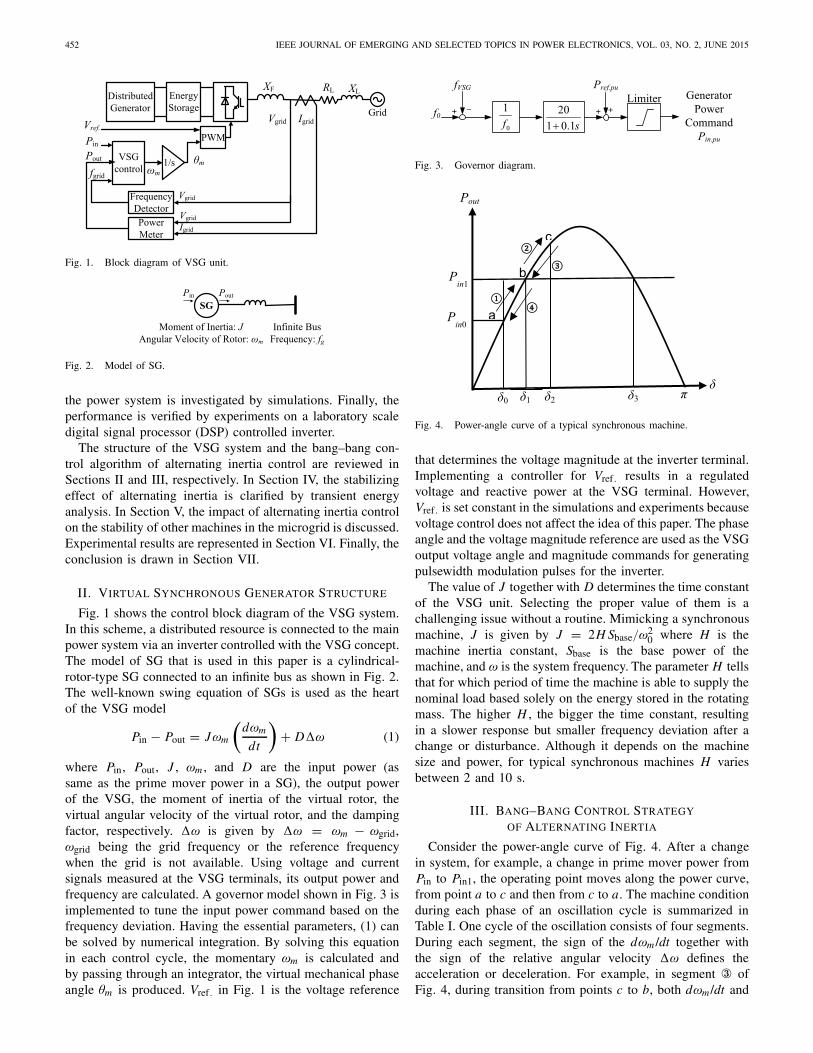
Fig. 4. Power-angle curve of a typical synchronous machine.
that determines the voltage magnitude at the inverter terminal.Implementing a controller for Vref. results in a regulatedvoltage and reactive power at the VSG terminal. However,Vref. is set constant in the simulations and experiments becausevoltage control does not affect the idea of this paper. The phaseangle and the voltage magnitude reference are used as the VSGoutput voltage angle and magnitude commands for generatingpulsewidth modulation pulses for the inverter.
The value of J together with D determines the time constantof the VSG unit. Selecting the proper value of them is achallenging issue without a routine. Mimicking a synchronousmachine, J is given by J = 2H Sbase/ω
20 where H is the
machine inertia constant, Sbase is the base power of themachine, and ω is the system frequency. The parameter H tellsthat for which period of time the machine is able to supply thenominal load based solely on the energy stored in the rotatingmass. The higher H , the bigger the time constant, resultingin a slower response but smaller frequency deviation after achange or disturbance. Although it depends on the machinesize and power, for typical synchronous machines H variesbetween 2 and 10 s.
III. BANG–BANG CONTROL STRATEGY
OF ALTERNATING INERTIA
Consider the power-angle curve of Fig. 4. After a changein system, for example, a change in prime mover power fromPin to Pin1, the operating point moves along the power curve,from point a to c and then from c to a. The machine conditionduring each phase of an oscillation cycle is summarized inTable I. One cycle of the oscillation consists of four segments.During each segment, the sign of the dωm /dt together withthe sign of the relative angular velocity �ω defines theacceleration or deceleration. For example, in segment ③ ofFig. 4, during transition from points c to b, both dωm /dt and

ALIPOOR et al.: POWER SYSTEM STABILIZATION USING VSG 453
TABLE I
MACHINE MODES DURING OSCILLATION
�ω are negative and act in the same direction; therefore, it isan acceleration period, whereas when they have opposite signslike segment ④, it is a deceleration period.
The objective is to damp frequency and power oscillationquickly by controlling the acceleration and deceleration term.The derivative of angular velocity, dωm /dt indicates the rateof acceleration or deceleration. Considering (1), it is observedthat this rate has a reverse relation to the moment of iner-tia, J . Based on this fact, one can select a large value of Jduring acceleration phases (a to b and c to b) to reduce theacceleration and a small value of J during deceleration phases(b to c and b to a) to boost the deceleration. The big momentof inertia Jbig and the small one Jsmall can be chosen within awide range depending on the rated power so that the differencebetween Jbig and Jsmall determines the damped power in eachhalf-cycle of oscillation by alternating inertia. The value ofJbig can be equal to the normal value of J . However, applyinga very larger value than the normal J will result in a smallerfrequency excursion at the first quarter-cycle but a sluggishresponse. The value of Jsmall determines the transient of thesecond quarter-cycle of oscillation. A very small value of Jsmall(<0.1 kgm2) will result in a satisfactory response.
The bang–bang control strategy is summarized in Table I.During each cycle of oscillations, the value of J is switchedfour times. Each switching happens at the points that thesign of either �ω or dωm /dt varies. Before the disturbance,the VSG is operating with the normal value of J. When thedisturbance happens, the transition from a to b starts with�ω > 0 and dωm/dt > 0. In this condition, the Jbig isadopted. At the end of the first quarter-cycle, that is point b,the sign of dωm /dt changes. It means that the small value forJ is adopted at this point. At point c, the sign of �ω changesand J retrieves it big value. It will be the end of the firsthalf-cycle. During the second half-cycle, the value of J isswitched to the Jsmall at point b, and again at the end of onecycle at point a, Jbig is adopted. This procedure is repeated foreach cycle of oscillation until the transients are suppressed and�ω equals zero at the new equilibrium point, that is, point b.A threshold for �ω can be applied to avoid the chattering ofJ during normal operation. However, this threshold is set tozero in this paper.
Figs. 5 and 6 show simulation results of this concept.Simulations were performed on the system model of Fig. 1with the parameters of Pbase = 50 kW, fbase = 60 Hz,RL = 12.5%, X L = 33.0%, X F = 42.4%, and D = 17 pu.The system was subjected to increase in the VSG powerreference in two steps of 70% and 30% at t = 2 s and t = 8 s,respectively. Fig. 5 shows the output power and frequency ofthe VSG with the fixed value of J = 6 kgm2. To show the
Fig. 5. Output power, virtual angular velocity, and virtual moment of inertiaof VSG with fixed J = 6 kgm2 and D = 17 pu.
Fig. 6. Output power, virtual angular velocity, and virtual moment of inertiaof VSG with alternating J : 1 and 6 kgm2 and D = 17 pu.
effectiveness of the proposed idea, simulations were carriedout on a weak system that VSG with fixed J cannot stabilizethe frequency at the second step of power increase. Then, thecontrol scheme of the VSG was changed to alternating inertiacontrol, and the same scenario was applied. As it is observedin Fig. 6, alternating inertia selects the values of J out ofJbig = 6 kgm2 and Jsmall = 1 kgm2. This process does notonly stabilize the system, but also suppresses the frequencyand power oscillations effectively.
Damping factor is an important term that defines theVSG response. An inappropriate value of damping factormay result in a high magnitude of oscillation or a sluggishresponse. Besides, a proper value of the damping factor ina specific working point may not end up with an acceptableresponse in other conditions. The alternating inertia conceptallows the VSG system to exert a suitable time constant ineach phase of oscillation; therefore, the importance of thedamping factor in the behavior of the VSG system is reducedconsiderably. To assess this matter, the damping factor waschanged to zero, and the same scenario was applied. Fig. 7shows the output power and angular velocity of the VSGin this condition. It is observed that the system operates

454 IEEE JOURNAL OF EMERGING AND SELECTED TOPICS IN POWER ELECTRONICS, VOL. 03, NO. 2, JUNE 2015
Fig. 7. Output power, virtual angular velocity, and virtual moment of inertiaof VSG with alternating J : 1 and 6 kgm2 and D = 0 pu.
stably, and the oscillations are eliminated by the alternatinginertia idea even with a zero value for the damping factor.
IV. STABILITY ASSESSMENT BY ENERGY
FUNCTION ANALYSIS
Transient stability concerns the stability of the rotor angleof synchronous machines (voltage angle in the case of VSG)after a significant disturbance. Having the advantage of notsolving the nonlinear differential equations, Lyapunov directmethod has become the center of attention for transientstability analysis. Consider a system expressed by a set ofnonlinear differential equations of the form x = F(x), x beinga vector of state variables. The point x for which F(x) = 0is the equilibrium point of the system in state space. Thesolution of system state equations from initial point to theequilibrium point forms the system trajectory. The trajectory ofan asymptotically stable system converges at the equilibriumpoint as time approaches infinity.
Based on the Lyapunov stability theorem, point x is asymp-totically stable if a continuous differentiable function V (x)exists and V (x) ≤ 0. In other words, the rate of change ofV (x) along the system trajectory is negative. The theorem isshown in Fig. 8. The V (x) of Fig. 8(a) is declining duringtime as state variables converge to the equilibrium point thatis a minimum stationary point, whereas for an unstable initialpoint, the value of V (x) rises, and the graph diverges on thestate variables plane as shown in Fig. 8(b).
Finding a candidate Lyapunov function is the next step ofstability analysis. Machowski et al. [18] calculated the energyfunction through removing the damping factor, multiplying theswing equation by �ω, and integrating the product from thefirst equilibrium point, that is, point b in Fig. 4, with δ1 and�ω = 0 to any point on the system transient trajectory. Theresultant expression is
V = Ek + E p = 1
2ω0 J�ω2−[Pin(δ − δ1) + b(cos δ − cos δ1)]
(2)
where V is the system transient energy after a change ordisturbance b is the amplitude of the power-angle curve, and
Fig. 8. Lyapunov’s theorem on stability [18]. (a) Transient energy leveldescends in a stable case. (b) Transient energy ascends in an unstable case.
ω is the system frequency. Equation (2) has two terms. Thefirst term, which is denoted as Ek , is the kinetic energyof the rotor of SG and virtual kinetic energy for the VSGsystem. The other term, E P is the potential energy that isstored and released electromagnetically during the interactionbetween the electromagnetic fields of the rotor and stator of themachine. It is proved that V satisfies the Lyapunov functioncriteria [18]. In the case of VSG with alternating moment ofinertia, only a presumption of J > 0 is needed.
When oscillation starts at point a of Fig. 4, �ω is zero andδ − δ1 is maximum. Therefore, Ek = 0 and E P is maximum.During the transition from point a to b with a large valueof J , Ek is increasing, and E p is decreasing as �ω increasesand δ − δ1 decreases. All system transient energy is convertedto the kinetic form at point b with maximum �ω and Jbig.At this point, the change in the moment of inertia to thesmall value is applied. Therefore, the system transient energywill be decreased to a smaller value kinetic form with thesame �ω but Jsmall. Now, this energy will be converted tothe potential form during the transition from point b to c as�ω decreases and δ − δ1 increases. Because the total energyhas decreased, the amplitude of oscillation will be reduced.In other words, δ2 − δ1 will be much smaller than δ − δ1.J adopts its big value at point c. However, all of the systemtransient energy is in potential form at this point as �ω = 0and δ − δ1 has its maximum value. Therefore, the increase inJ does not increase the system energy level based on (2). Thisprocess happens in each half-cycle until �ω becomes less thana desired threshold.
To see the damping effect of the alternating moment ofinertia scheme, we consider the third criterion of the Lyapunovfunction. This criterion demands that the derivative of theenergy function is negative. Thus, the system transient energydeclines during time until the system state variables are settledat the equilibrium point. For a VSG with variable J by calcu-lating the derivatives of Ek and E p separately and consideringthe swing equation, the derivative of V is expressed as
dV
dt= ω0
2�ω2 d J
dt− D�ω2. (3)
This expression must be negative to have decay in thesystem transient energy during oscillation. The term −D�ω2

ALIPOOR et al.: POWER SYSTEM STABILIZATION USING VSG 455
Fig. 9. Transient energy trajectory after a step change in power reference ofVSG with (a) fixed moment of inertia and (b) alternating inertia.
is obviously negative for D > 0. Because J variesdiscontinuously, dJ/dt is approximated by its average valueat the points at which J is switched. At points a and c atwhich J is varied from Jsmall to Jbig, the variation of J ispositive (�J = Jbig − Jsmall). However, dJ/dt is multipliedby �ω2 in (3) and �ω is zero at these points. It means that,the variation of J does not change the transient energy atthese points. Inversely, at point b, at which J is varied fromJbig to Jsmall, �J is calculated as Jsmall − Jbig, and �ω hasits maximum value. Therefore, the term dJ/dt is effective atthis point and it is estimated for each half-cycle as follows:
d J
dt≈ �J
�t= Jsmall − Jbig
0.5T. (4)
Assuming a zero damping factor D, (3) can be rewritten as
dV
dt= ω0
2�ω2 Jsmall − Jbig
0.5T< 0. (5)
Equation (5) shows that an additional damping effect isimposed in each half-cycle by varying the value of the momentof inertia. This damping acts directly on the transient energyand cuts it to a desired level decided by the difference in thevalues of J . Fig. 9 shows the performance of the alternatinginertia method in transient energy suppression. Simulationswere performed on the system model of Fig. 1. Fig. 9(a)contains the system transient energy trajectory for a VSG withthe fixed moment of inertia of 6 kgm2 after a step increase of1 pu in power reference. It is observed that the system transientenergy declines by the damping factor as the state variablesconverge to the equilibrium point. When the alternating inertiascheme is applied, the transient energy drops to a desired levelby applying the small J of 3 kgm2, as shown in Fig. 9(b).By adopting a tiny Jsmall, fast decay of transient energy canbe achieved, which bypasses the state variables to the stablestationary point in the first half-cycle.
There is another stationary point for the swing equation,with �ω = 0 and δ = π − δ1 (that equals δ3 in Fig. 4).The value of the energy function at this point is the criticaltransient energy. For a SG and VSG with fixed inertia, thevalue of energy function at the initial point of oscillation mustbe smaller than the critical value. However, in the case of VSGwith alternating inertia scheme, any starting energy level can
Fig. 10. Kinetic energy (Ek), potential energy (E P), and total transientenergy (V ) waveforms after a step increase in power reference of VSG with(a) fixed moment of inertia and (b) alternating inertia.
Fig. 11. VSG unit in parallel with the SG in microgrid.
be reduced to nearly zero value at the end of the first quarter-cycle; therefore, the critical transient energy and therebytransient stability area will always have its maximum value,that is, 2b − π Pm . Other corollaries regarding the transientstability area and the critical clearance time that can be inferredfrom the alternating inertia concept are forgone because ofprolixity. The system kinetic, potential, and total energy inthe same simulation condition as Fig. 9 are plotted in Fig. 10.
V. GRID STABILITY ENHANCEMENT
BY ALTERNATING INERTIA
A. VSG in Parallel With Other Machines
In microgrid applications, an inverter-based DG worksin parallel with other DGs that may include synchronousmachines. Consider the islanded microgrid of Fig. 11. TheVSG block has the control scheme shown in Fig. 1 with theoutput filter inductance of 9.7%. The objective of this part is toassess the effect of the alternating inertia scheme of the VSGon the stability of the parallel SG. To clarify the effectivenessof the idea, the capacity of the VSG unit was assumed tobe 20% of the SG that is insignificant. A symmetrical faulthappened at the load point at t = 0.2 s and lasted for 0.3 s.In this condition, the system comprising the VSG with thefixed value of moment of inertia J = 8.445 kgm2 was notable to recover from the fault as shown in Fig. 12. Thesame scenario was applied to the system with alternatinginertia of Jbig = 8.445 and Jsmall = 0.0844 kgm2. Thewaveforms of power, SG rotor angle, and angular frequencyare shown in Fig. 13. As it is observed, the alternating inertiascheme improved the stability of the adjacent machine bythe extra damping effect imposed on the transient energydirectly.
B. VSG as an Interface Between the SG and Grid
Another configuration is shown in Fig. 14. An SG isconnected to the grid/microgrid through a VSG unit. Theprime mover of the SG can be a gas or diesel engine, and an

456 IEEE JOURNAL OF EMERGING AND SELECTED TOPICS IN POWER ELECTRONICS, VOL. 03, NO. 2, JUNE 2015
Fig. 12. VSG and SG powers and SG rotor angle waveforms of the systemwith fixed moment of inertia and D = 17 pu.
Fig. 13. VSG and SG powers and SG rotor angle waveforms of the systemwith alternating inertia control and D = 0 pu.
Fig. 14. SG connected to the grid via VSG unit.
inverter interface is required to correct the generated power tobe injected to the grid. If the VSG unit is not robust enough,the disturbances from grid/microgrid will affect the stableoperation of the SG. To assess the effect of the alternatinginertia control on the stability of such systems, a symmetricalthree-phase voltage sag with 10% remained voltage magnitudeand the duration of 0.2 s was applied from grid side, andthe performance of the system was monitored. The referencepower and damping factor of the VSG were 1 and 17 pu,respectively, and a fixed inertia factor equal to 5 kgm2 wasapplied. Fig. 15 shows the SG rotor angle and dc-link voltagewere affected by the grid voltage sag considerably. Thehigh-peak transient of dc-link voltage is mainly because ofthe oscillation of the VSG output power. The same sce-nario was applied to the system with the alternating inertiacontrol with Jbig = 5 and Jsmall = 0.05 kgm2. To dis-criminate the stabilizing effect of alternating inertia as theonly stabilizing effect in the system, the damping factor Dwas set to zero. It should be mentioned that the systemwith fixed inertia and a zero damping factor was unableto recover from much milder faults. As it is observed inFig. 16, the oscillation was suppressed by the alternating
Fig. 15. SG load angle and dc-link voltage of the system of Fig. 14 containingVSG with fixed moment of inertia.
Fig. 16. SG load angle and dc-link voltage of the system of Fig. 14 containingVSG with alternating inertia.
Fig. 17. Experimental system.
inertia scheme, and the severe transient of dc-link voltage wasalso eliminated.
VI. EXPERIMENTAL RESULTS
The damping effect of alternating inertia was verified byapplying to a laboratory-scale test system. The overall systemconfiguration is shown in Fig. 17, and the main parametersof the system are presented in Table II. The transmission unitin Fig. 17 simulates the π model of a 40 km transmission lineshown in Fig. 18.
Initially, the VSG with the constant moment of inertiaJ = 0.563 kgm2 was subjected to a step change of 3 kWin the power reference. This value of J is calculated byassuming the inertia constant H = 8 s at rated power andfrequency. The output power and angular velocity of the VSGis shown in Fig. 19. When the power reference increased,the VSG output power followed the power command afterpassing severe oscillations with the amplitude of 2 kW. TheVSG stopped operating by applying 3.6 kW power command.Fig. 20 shows the RMS values of the VSG voltage and

ALIPOOR et al.: POWER SYSTEM STABILIZATION USING VSG 457
TABLE II
SPECIFICATIONS OF THE EXPERIMENTAL SYSTEM
Fig. 18. π model of a 40 km transmission line.
Fig. 19. Output power and virtual angular velocity of VSG with fixed momentof inertia of 0.563 kgm2 and D = 17 pu.
Fig. 20. RMS values of the VSG current and voltage with the fixed momentof inertia of 0.563 kgm2 and D = 17 pu subjected to a 3.6 kW step powerincrease.
current in this condition. Because of the severe oscillation,the VSG current exceeded its tolerable limit and the inverterwas stopped at t = 1.43 s.
Then, the VSG control was changed to the alternating inertiascheme with Jbig = 0.563 kgm2 and Jsmall = 0.1 kgm2, andthe step power change of 45 kW was applied. The result isshown in Fig. 21. It is observed that the VSG follows thepower command without oscillations. It can be concluded thatthe VSG with alternating inertia can be loaded reliably atpower levels close to its rating, and also can ride-throughseverer changes or disturbances. The effectiveness of thealternating inertia in the smooth transition of current level and
Fig. 21. RMS current, RMS voltage, output power, virtual angular velocity,and virtual moment of inertia of VSG with alternating J and D = 17 pu aftera power command of 4.5 kW.
Fig. 22. Output power, virtual angular velocity, and moment of inertia ofVSG with alternating J and D = 0 pu.
reducing the voltage ripples at the VSG terminal is obviousin this figure.
To clarify the damping effect of the alternating inertiascheme, the VSG with alternating inertia and zero dampingfactor D is subjected to a change of 3 kW in the powerreference. It must be noted that the VSG with fixed inertia andzero damping factor cannot get into step with grid frequencyand fails to track power reference after any disturbance. Outputpower, virtual angular velocity, and the real-time adopted J areshown in Fig. 22. As it is expected, the VSG can track thepower reference with negligible transients.

458 IEEE JOURNAL OF EMERGING AND SELECTED TOPICS IN POWER ELECTRONICS, VOL. 03, NO. 2, JUNE 2015
VII. CONCLUSION
In this paper, the alternating inertia structure was elaborated.The alternating inertia scheme adopts the suitable value ofthe moment of inertia of the VSG considering its virtualangular velocity and acceleration/deceleration in each phaseof oscillation. By selecting a big value for the moment ofinertia during acceleration, the haste was mitigated, and on theother hand, during deceleration, a small value for inertia factorwas adopted to increase the deceleration effect. The systemtransient energy analysis was used to assess the stabilizingeffect of alternating inertia control. It was clarified by theenergy analysis that the system transient energy is reducedpromptly by the reduction in the value of the moment ofinertia. Actually, in the case of a real synchronous machine,this transient energy is dissipated by damping terms duringoscillations, whereas the alternating inertia control eliminatesthe transient energy directly and prevents its flow from dc stor-age and dissipation. Compared to normal damping factor D,the damping exerted by alternating inertia is considerablymore effective and has identical results in any conditions.In addition, the transient energy can be reduced to zeroat the end of the first quarter-cycle by alternating inertiacontrol. Therefore, any transients can be eliminated beforeappearing. The idea does not only stabilize the VSG unit, butalso enhances the stability of other machines in the system.Two configurations were assessed by simulation and the sta-bilizing effect of alternating inertia on the adjacent machineswas illustrated. The proposed scheme was realized on theexperimental system and the results affirmed the outstandingstabilizing effect of alternating inertia.
REFERENCES
[1] Q.-C. Zhong and T. Hornik, Control of Power Inverters in RenewableEnergy and Smart Grid Integration. New York, NY, USA: Wiley, 2013.
[2] L. Zhang, L. Harnefors, and H.-P. Nee, “Power-synchronization controlof grid-connected voltage-source converters,” IEEE Trans. Power Syst.,vol. 25, no. 2, pp. 809–820, May 2010.
[3] F. Blaabjerg, R. Teodorescu, M. Liserre, and A. V. Timbus, “Overviewof control and grid synchronization for distributed power generationsystems,” IEEE Trans. Ind. Electron., vol. 53, no. 5, pp. 1398–1409,Oct. 2006.
[4] Q.-C. Zhong, P.-L. Nguyen, Z. Ma, and W. Sheng, “Self-synchronizedsynchronverters: Inverters without a dedicated synchronization unit,”IEEE Trans. Power Electron., vol. 29, no. 2, pp. 617–630, Feb. 2014.
[5] J. Driesen and K. Visscher, “Virtual synchronous generators,” in Proc.IEEE Power Energy Soc. General Meeting-Convers. Del. Elect. Energy21st Century, Jul. 2008, pp. 1–3.
[6] T. Loix, S. De Breucker, P. Vanassche, J. Van den Keybus, J. Driesen,and K. Visscher, “Layout and performance of the power electronicconverter platform for the VSYNC project,” in Proc. IEEE PowertechConf., Jun./Jul. 2009, pp. 1–8.
[7] Q.-C. Zhong and G. Weiss, “Synchronverters: Inverters that mimicsynchronous generators,” IEEE Trans. Ind. Electron., vol. 58, no. 4,pp. 1259–1267, Apr. 2011.
[8] M. P. N. van Wesenbeeck, S. W. H. de Haan, P. Varela, andK. Visscher, “Grid tied converter with virtual kinetic storage,” inProc. IEEE Bucharest PowerTech, Bucharest, Romania, Jun./Jul. 2009,pp. 1–7.
[9] M. Torres and L. A. C. Lopes, “Virtual synchronous generator controlin autonomous wind-diesel power systems,” in Proc. IEEE Elect. PowerEnergy Conf. (EPEC), Montreal, QC, Canada, Oct. 2009, pp. 1–6.
[10] V. Karapanos, S. de Haan, and K. Zwetsloot, “Real time simulation ofa power system with VSG hardware in the loop,” in Proc. 37th Annu.Conf. IEEE Ind. Electron. Soc. (IECON), Nov. 2011, pp. 3748–3754.
[11] R. Hesse, D. Turschner, and H.-P. Beck, “Micro grid stabilization usingthe virtual synchronous machine,” in Proc. Int. Conf. Renew. EnergiesPower Quality (ICREPQ), no. 472, pp. 1–6, Apr. 2009.
[12] Y. Xiang-Zhen, S. Jian-Hui, D. Ming, L. Jin-Wei, and D. Yan, “Controlstrategy for virtual synchronous generator in microgrid,” in Proc. 4thInt. Conf. Electr. Utility Deregulation Restruct. Power Technol. (DRPT),Jul. 2011, pp. 1633–1637.
[13] N. Soni, S. Doolla, and M. C. Chandorkar, “Improvement of transientresponse in microgrids using virtual inertia,” IEEE Trans. Power Del.,vol. 28, no. 3, pp. 1830–1838, Jul. 2013.
[14] K. Sakimoto, Y. Miura, and T. Ise, “Stabilization of a power system witha distributed generator by a virtual synchronous generator function,” inProc. IEEE 8th Int. Conf. Power Electron. ECCE Asia (ICPE & ECCE),May/Jun. 2011, pp. 1498–1505.
[15] J. Alipoor, Y. Miura, and T. Ise, “Evaluation of virtual synchronousgenerator (VSG) operation under different voltage sag conditions,” inProc. IEE Jpn. Joint Tech. Meeting Power Eng. Power Syst. Eng., Tokyo,Japan, 2012, pp. 41–46.
[16] T. Shintai, Y. Miura, and T. Ise, “Reactive power control for load sharingwith virtual synchronous generator control,” in Proc. Power Electron.Motion Control Conf. (IPEMC), Jun. 2012, pp. 846–853.
[17] J. Alipoor, Y. Miura, and T. Ise, “Distributed generation grid integra-tion using virtual synchronous generator with adoptive virtual inertia,”in Proc. IEEE Energy Convers. Congr. Expo. (ECCE), Sep. 2013,pp. 4546–4552.
[18] J. Machowski, J. Bialek, and J. Bumby, Power System Dynam-ics: Stability and Control, 2nd ed. Chippenham, U.K.: Wiley, 2008,pp. 222–230.
Jaber Alipoor received the B.Sc. degree from theDepartment of Electrical Engineering, University ofMazandaran, Babolsar, Iran, in 2007, and the M.Sc.degree from the Department of Electrical Engineer-ing, Shahed University, Tehran, Iran, in 2010. Heis currently pursuing the Ph.D. degree with OsakaUniversity, Suita, Japan.
His current research interests include power sys-tem stability, power quality, and distributed powergeneration.
Yushi Miura received the Dr.Ing. degree in elec-trical and electronic engineering from the TokyoInstitute of Technology, Tokyo, Japan, in 1995.
He was with the Japan Atomic Energy ResearchInstitute, Osaka University, Suita, Japan, from 1996to 2004, where he is currently an Associate Profes-sor with the Division of Electrical, Electronic, andInformation Engineering. He is studying applicationsof power electronics to power systems.
Toshifumi Ise received the Dr.Ing. degree in electri-cal engineering from Osaka University, Suita, Japan,in 1986.
He is currently a Professor with the Division ofElectrical, Electronic, and Information Engineering,Graduate School of Engineering, Osaka Univer-sity. His current research interests include powerelectronics and applied superconductivity, includingpower quality issues, such as voltage sag compen-sator, superconducting magnetic energy storage, andnew distribution systems, including many distributed
generations.