HVAC Water-side Systems
60
HVAC Water-side Systems Dr. Sam C. M. Hui Department of Mechanical Engineering The University of Hong Kong E-mail: [email protected] Jan 2016 MECH3423 Building Services Engineering II http://me.hku.hk/bse/MECH3423/
Transcript of HVAC Water-side Systems

HVAC Water-side Systems
Dr. Sam C. M. HuiDepartment of Mechanical Engineering
The University of Hong Kong
E-mail: [email protected]
Jan 2016
MECH3423 Building Services Engineering IIhttp://me.hku.hk/bse/MECH3423/

Contents
• Pipe Systems and Design
• Water Systems in HVAC
• Centrifugal Pumps
• Pump Arrangements

Pipe Systems and Design
• Common types of HVAC piping systems
• Chilled water (CHW) system
• Condenser water (CW) system
• Sea water system
• Hot water supply system
• Steam pipes, gas pipes
• Similar systems in other building services
• Water supply & distribution (plumbing)

[Source: Kreider, K. F. (ed.), 2001. Handbook of Heating, Ventilation, and Air Conditioning, CRC Press, Boca Raton, FL.]

Pipe Systems and Design
• Two major concerns:
• Size the pipe (e.g. from charts & tables)
• Determine the flow-pressure relationship
• To analyse the system, e.g. to find out pump pressure
• By using manual or computer-based methods
• Calculations for pipelines or pipe networks
• Can be very complicated for branches & loops
• Basic parameters: pipe diameter, length, friction factor, roughness, velocity, pressure drop

Pipe Systems and Design
• Basic equations
• Darcy-Weisbach Equation (for fully developed
flows of all Newtonian fluids)
• Colebrook-White Equation (for transition region):
• * The equation is implicit in f (appears on both sides), so
iterations are required to solve for f.
=∆
=∆
g
V
D
Lfh
g
V
D
Lfp
2or
2
22ρ
+−+=
fDD
f )/Re(
3.91log2)/log(214.1
1
εε
Pipe Systems and Design
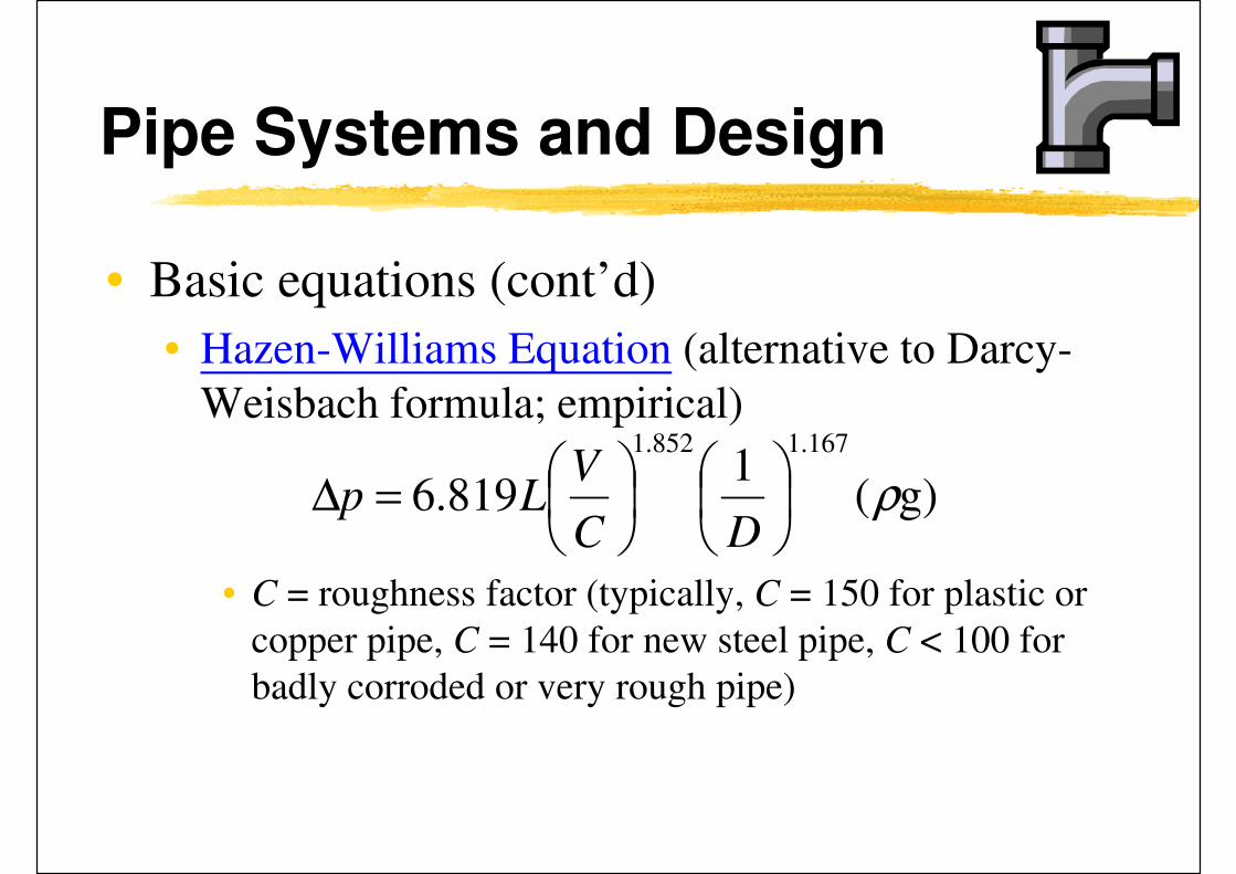
• Basic equations (cont’d)
• Hazen-Williams Equation (alternative to Darcy-
Weisbach formula; empirical)
• C = roughness factor (typically, C = 150 for plastic or
copper pipe, C = 140 for new steel pipe, C < 100 for
badly corroded or very rough pipe)
g)(1
819.6
1.167852.1
ρ
=∆
DC
VLp

Pipe Systems and Design
• Valve and fitting losses
• May be greater than pipe friction alone
• KL = loss coefficient (K factor) of pipe fittings
• Geometry and size dependent
• May be expressed as equivalent lengths of straight pipe
• Valve coefficient (Av):
• Volume flow rate
=∆
=∆
g
VKh
VKp LL
2or
2
22
ρ
ρ/pAQ v ∆=

(Source: Larock, Jeppson and Watters, 2000: Hydraulics of Pipeline Systems)

Pipe Systems and Design
• Practical design issues
• Select a pipe size for desired total flow rate and available or allowable pressure drop, e.g.
• Often assume 2.5 m / 100 m pipe length
• Velocity limit 1.2 m/s for pipe < 50 mm dia., pressure drop limit 400 Pa/m for pipe > 50 mm dia.
• Rule of thumb for practical design:
• Assume design pipe length is 1.5 to 2.0 times actual to account for fitting losses; after pipe diameter is selected, then evaluate the influence of each fitting
• Other considerations: e.g. noise & water hammer

(Source: ASHRAE Handbook Fundamentals 2005, Chp. 36)

(Source: ASHRAE Handbook Fundamentals 2005, Chp. 36)

Water Systems in HVAC
• HVAC water systems can be classified by
• Operating temperature
• Flow generation
• Pressurization
• Piping arrangement
• Pumping arrangement

Water Systems in HVAC
• Open water systems, e.g. using cooling tower
• Closed water systems
• Chilled water (CHW) system [4-13 oC, 825 kPa]
• Condenser water (CW) system
• Dual temperature water system
• Low temp. water (LTW) system [Max. 120 oC, < 1100 kPa]
• Medium temp. water (MTW) system [120-125 oC, < 1100 kPa]
• High temp. water (HTW) system [> 175 oC, > 2070 kPa]
• Once-through system, e.g. sea water system

Basic components of water (hydronic) system
(Source: ASHRAE HVAC Systems and Equipment Handbook 2004)
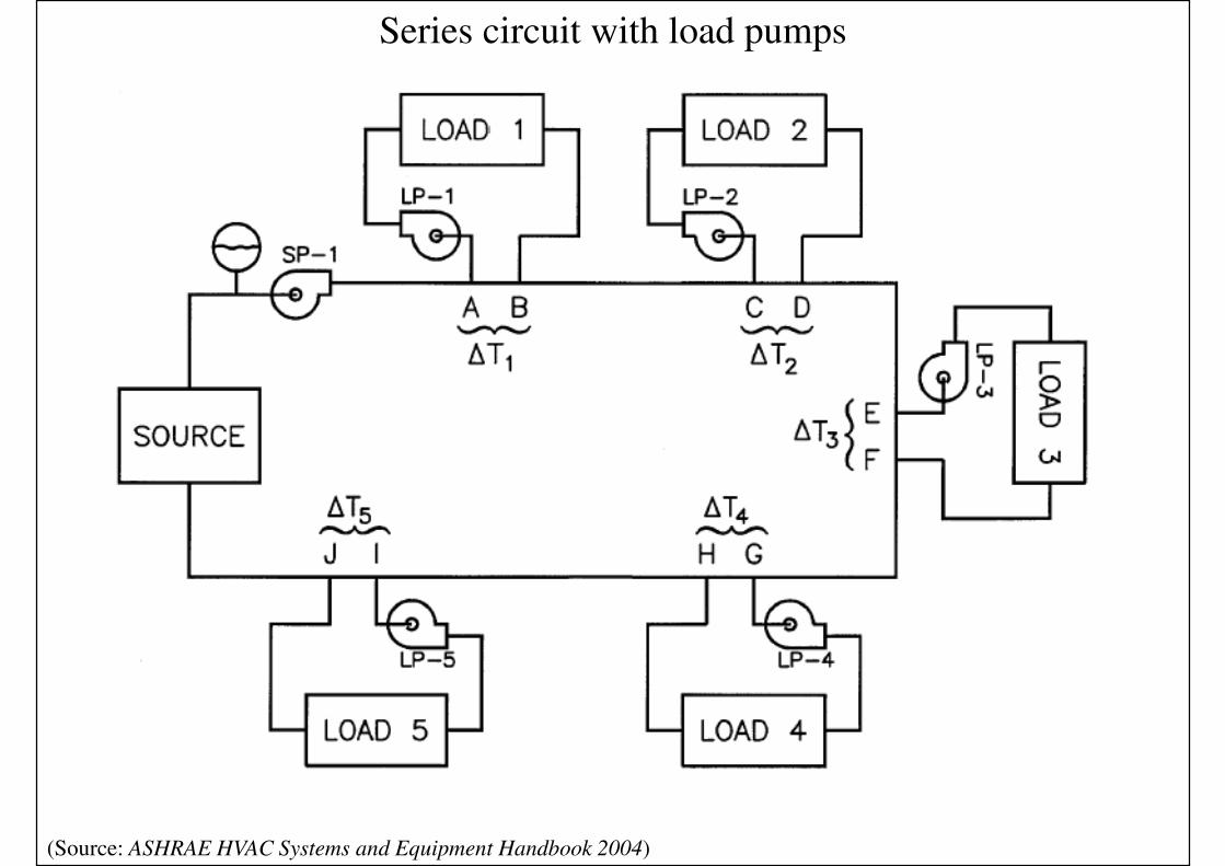
Series circuit with load pumps
(Source: ASHRAE HVAC Systems and Equipment Handbook 2004)

Primary-secondary loop and pumping
(Source: ASHRAE HVAC Systems and Equipment Handbook 2004)
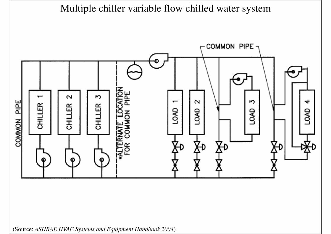
Multiple chiller variable flow chilled water system
(Source: ASHRAE HVAC Systems and Equipment Handbook 2004)

2-pipe direct return 2-pipe reverse return
(Source: ASHRAE HVAC Systems and Equipment Handbook 2004)

4-pipe system (dual temperature)
(Source: ASHRAE HVAC Systems and Equipment Handbook 2004)

Water Systems in HVAC
• Heat transfer in water systems
• Terminal units/devices that convey heat from/to water for heating/cooling
• Common heat exchangers
• Water-to-air finned coil
• Water-to-water
• Heating load devices, e.g. radiators
• Cooling load devices, e.g. fan coil units (FCU)
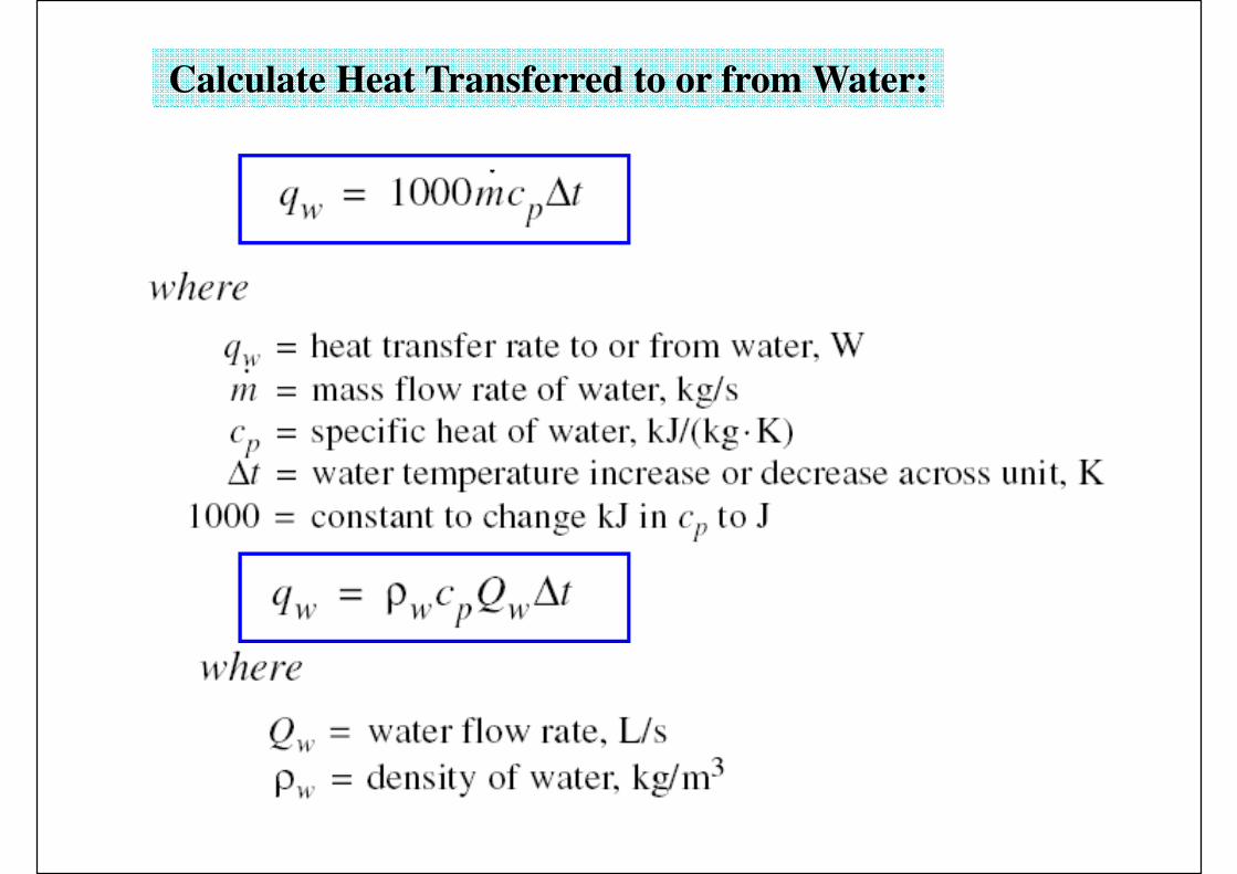
Calculate Heat Transferred to or from Water:

Water Systems in HVAC
• Design issues
• Design water temperature
• Flow rate
• Piping layout
• Pump selection
• Terminal unit selection
• Control method

Water Systems in HVAC
• Design principles
• Constant flow? Variable flow? Intermittent flow?
• Direct return piping or reverse return piping
• Direct return riser & reverse zone piping
• Design factors
• Pump speed controls
• Pressure distribution
• System balancing
• Thermal expansion & joints (or loops)

Water Systems in HVAC
• Piping materials
• Chilled water: black & galvanized steel
• Hot water: black steel, hard copper
• Condenser water: black steel, galvanized ductile iron, PVC
• Flow rate measurements
• Venturi, nozzle & orifice flowmeters
• Variable area flowmeters (rotameters)
• Turbine flowmeters

Water Systems in HVAC
• Other design considerations
• Makeup water (from city water or wells)
• Safety relief valves (for pressurised systems)
• Air elimination (e.g. by air separator/vent)
• Drain (at low points) & shutoff (for isolation)
• Balance fittings (allow balancing of sub-circuits)
• Strainers (remove dirt)
• Insulation (reduce heat loss & condensation)
• Condensate drains (to drainage system or recover)

Water Systems in HVAC
• Practical design process (see reference)• See “Practical Guide to HVAC Building Services
Calculations” - water flow distribution systems: overview of system design process
• W1 Pipe sizing – general
• W2 Pipe sizing – straight length
• W3 Pipe sizing – pressure drop across fittings
• W4 System resistance for pipework – index run
• W5 Pump sizing
• W6 Water system pressurisation

Centrifugal Pumps
• Centrifugal pump
• Most widely used in HVAC applications, e .g.
• Hot water systems
• Chilled water systems
• Condenser water systems
• Boiler feed and condensate return pumps
• Operation
• Electric motor’s output torque => impeller’s rotation
• Coupling to the pump shaft
• Centrifugal force & tip speed force

(Source: Fundamentals of Water System Design)
Chilled water pumping system

Cooling tower pumping system
(Source: Fundamentals of Water System Design)

(Source: Wang, S. K., 2001. Handbook of Air Conditioning and Refrigeration)
A double-suction, horizontal split-case, single-stage centrifugal pump
Pump motor Centrifugal pump body
Pump Shaft

(Source: ASHRAE HVAC Systems and Equipment Handbook 2012)
Centrifugal pump
* Video: How does a Centrifugal pump work ? (4:37) http://www.youtube.com/watch?v=BaEHVpKc-1Q
http://www.learnengineering.org/2014/01/centrifugal-hydraulic-pumps.html

(Source: Fundamentals of Water System Design)
Centrifugal pump, impeller and volute

(Source: Fundamentals of Water System Design)
Impeller action on fluid
* Video: Centrifugal Pump Working (5:54) http://www.youtube.com/watch?v=IiE8skW8btE
http://www.learnengineering.org/2013/03/centrifugal-pump.html
Centrifugal Pumps
• Variable speed pumps
• Less expensive nowadays
• Centrifugal pump characteristics*
• Total pressure-capacity curve
• Flat curve: applied on closed piping systems with
modulating valves
• Steep curve: usually for open piping systems (cooling
towers), w/ high pressure, constant flow
• Family of pump performance curves
* Video: Centrifugal Pumps | Design Aspects (5:32) http://www.youtube.com/watch?v=pWSyrxFJmt4
http://www.learnengineering.org/2013/03/centrifugal-pumps-design-aspects.html

(Source: Fundamentals of Water System Design)
Total pressure-capacity curve

Flat versus steep pump curves
What
does this
imply?
(Source: Fundamentals of Water System Design)

Characteristic curves for pump models
(Source: Fundamentals of Water System Design)

Selected pump pressure-capacity curve
(Source: Fundamentals of Water System Design)
Centrifugal Pumps
• System pressure characteristic curve
• Compared w/: fan-duct system characteristics
• System operating point: intersection of fan curve
& system curve
• Pump power (W) = flow (L/s) x pressure (kPa)
• Pump input power
• Pump efficiency
• Matching pump to system curve
• Best efficiency point

(Source: ASHRAE HVAC Systems and Equipment Handbook 2004)
Pump curve and system curve

Increase of pumping power required with pump flow
(Source: Fundamentals of Water System Design)

Pump efficiency
(Source: Fundamentals of Water System Design)

Pump efficiency curves
(Source: Fundamentals of Water System Design)

Centrifugal Pumps
• Similarity relationships
• Pump affinity laws (c.f. fan laws)
Function Speed change Impeller diameter
change
Flow Q2 = Q1 (N2/N1) Q2 = Q1 (D2/D1)
Pressure p2 = p1 (N2/N1)2 p2 = p1 (D2/D1)
2
Power P2 = P1 (N2/N1)3 P2 = P1 (D2/D1)
3

Centrifugal Pumps
• Pump affinity laws (example)
• A pump is rated at 15 L/s at 200 kPa with a 24 rpm
electric motor. What is the flow and pressure if
used with a 16 rps motor? Assume no system static
pressure.
• Solution:
• Flow: Q2 = Q1 (N2/N1) = 15 (16/24) = 10 L/s
• Pressure: p2 = p1 (N2/N1)2 = 200 (16/24)2 = 88.9 kPa

(Source: ASHRAE HVAC Systems and Equipment Handbook 2004)
Region of best efficiency and best efficiency area

Pump Arrangements
• Pump selection process
• Determine the load to be pumped
• Determine design ∆t & calculate required flow
• Sum up the load flows to determine total flow
• Determine the “critical path” (most resistant)
• Determine mounting method & support
• Select a pump from manufacturer
• Flat curve & steep curve, pump operation & motor
• Check overflow capacity when staging multiple pumps

(Source: ASHRAE HVAC Systems and Equipment Handbook 2004)
Pump selection regions

(Source: Grundfos)
Reduction of theoretical Euler head due to losses

(Source: Grundfos)
Increase in power consumption due to losses

(Source: Fundamentals of Water System Design)
Pump performance data

Pump Arrangements
• Pumping arrangements & control scenarios
• Multiple pumps in parallel or series
• Standby pump
• Pumps with two-speed motors
• Primary-secondary pumping
• Variable-speed pumping
• Distributed pumping

Pump curve for parallel operation
(Source: Fundamentals of Water System Design)

Operating conditions for parallel pump installation
(Source: Fundamentals of Water System Design)

(Source: ASHRAE HVAC Systems and Equipment Handbook 2004)

(Source: ASHRAE HVAC Systems and Equipment Handbook 2004)

(Source: Fundamentals of Water System Design)
Pump curve for series operation

Operating conditions for series pump
(Source: Fundamentals of Water System Design)

(Source: ASHRAE HVAC Systems and Equipment Handbook 2004)