High Strain Rate Testing Recommended Practice (1)
30
Recommendations for Dynamic Tensile Testing of Sheet Steels By High Strain Rate Experts Group Michael Borsutzki (ThyssenKrupp Stahl) Dominique Cornette (Arcelor) Yukihisa Kuriyama (Nippon Steel Corporation) Akihiro Uenishi (Nippon Steel Corporation) Benda Yan (Mittal Steel, U.S.A.) Ed Opbroek (IISI) August 2005 International Iron and Steel Institute
-
Upload
thuyet-van-vu -
Category
Documents
-
view
220 -
download
0
Transcript of High Strain Rate Testing Recommended Practice (1)

8/11/2019 High Strain Rate Testing Recommended Practice (1)
http://slidepdf.com/reader/full/high-strain-rate-testing-recommended-practice-1 1/30
Recommendations for Dynamic Tensile Testing of Sheet Steels
By
High Strain Rate Experts Group
Michael Borsutzki (ThyssenKrupp Stahl)
Dominique Cornette (Arcelor)
Yukihisa Kuriyama (Nippon Steel Corporation)
Akihiro Uenishi (Nippon Steel Corporation)
Benda Yan (Mittal Steel, U.S.A.)
Ed Opbroek (IISI)
August 2005
International Iron and Steel Institute
8/11/2019 High Strain Rate Testing Recommended Practice (1)
http://slidepdf.com/reader/full/high-strain-rate-testing-recommended-practice-1 2/30
Recommendations for Dynamic Tensile Testing of Sheet Steels - August 2005
ii
Contents
Page
1. Introduction ……………………………………………………… 1
2. Scope ……………………………………………………………. 2
3. Some Features of High Strain Rate Tensile Testing …………….. 2
4. Machine Types …………………………………………………... 35. Input Methods …………………………………………………… 7
6. Specimens ………………………………………………………. 7
7. Clamping Methods ………………………………………………. 9
8. Measurement Devices …………………………………………… 10
9. Assessment and Improvement of Data Quality ………………….. 14
References ……………………………………………………………… 16
Appendices
Appendix I Tension Split Hopkinson Bar …………………………… 18Appendix II One Bar Method ………………………………………... 21
Appendix III Calculation of the Maximum Strain for SHB System ….. 24
Appendix IV Examples of Specimen Geometry ……………………… 25
Appendix V Improvement of Data Quality for One Bar Method ……. 28
8/11/2019 High Strain Rate Testing Recommended Practice (1)
http://slidepdf.com/reader/full/high-strain-rate-testing-recommended-practice-1 3/30
1
Recommendations for Dynamic Tensile Testing of Sheet Steels
August 2005
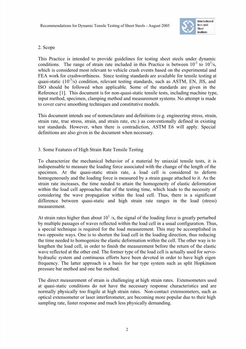
1. Introduction
Dynamic tensile testing of sheet steels is becoming more important due to the need for
more optimized vehicle crashworthiness analysis in the automotive industry. Positive
strain rate sensitivity, i.e. the strength increases with strain rate, offers a potential for
improved energy absorption during a crash event.
Different types of testing techniques have been used to generate data under dynamic
conditions. Each serves for a specific range of strain rates and provides specific type of
information. Servo-hydraulic system, tensile Split Hopkinson Bar (SHB) system,
compression Split Hopkinson Bar system, Single Bar (SB) system and drop weight
system are some of the systems commonly used. New systems also are been developed
in recent years to meet the increasing demand for dynamic testing. However, no
guidelines are available as to the testing method, specimen dimensions, measurement
devices, and other important issues which are critical to the quality of testing results. As
the result, data from different laboratories are often not comparable. Quality of the testing
data is, in general, not satisfactory. Signal damping and curve smoothing are often
necessary to make the testing data usable.
With the increasing needs for tensile stress-strain data at dynamic conditions for steels,
the International Iron and Steel Institute Committee on Automotive Applications (IISI-
AutoCo) decide to develop a Recommended Practice for Dynamic Tensile Testing for
Sheet Steels. A team composed of testing experts from Arcelor, Ispat Inland Inc. (now
Mittal Steel), Nippon Steel Corporation and ThyssenKrupp Stahl, was commissioned in
March 2003 to draft the document. Testing facilities and experiences from major testing
laboratories with sheet steel experiences were compiled, including Arcelor, Colorado
School of Mine, Ispat Inland Inc., JFE, Nippon Steel Corporation, POSCO, Sumitomo
Metals, Technical University of Aachen, ThyssenKrupp Stahl, University of Dayton
Research Institute and University of California at San Diego. This recommended testing practice is developed based on the information collected and experiences from the major
steel companies in IISI. After the draft of the document was developed, a Round Robin
test program was launched in early 2004 and completed in early 2005. Based on the
results from the Round Robin test program, the document was modified again and the
specimen geometry was further refined. Due to the limited time available, some testing
techniques may not be included in this document. However, it is the belief of the team
that this document covers most testing techniques for sheet steels and provides a starting
point for a standard testing procedure in the near future.
8/11/2019 High Strain Rate Testing Recommended Practice (1)
http://slidepdf.com/reader/full/high-strain-rate-testing-recommended-practice-1 4/30
Recommendations for Dynamic Tensile Testing of Sheet Steels - August 2005
2
2. Scope
This Practice is intended to provide guidelines for testing sheet steels under dynamicconditions. The range of strain rate included in this Practice is between 10-3 to 103/s,
which is considered most relevant to vehicle crash events based on the experimental and
FEA work for crashworthiness. Since testing standards are available for tensile testing at
quasi-static (10-3/s) condition, relevant testing standards, such as ASTM, EN, JIS, and
ISO should be followed when applicable. Some of the standards are given in the
Reference [1]. This document is for non-quasi-static tensile tests, including machine type,
input method, specimen, clamping method and measurement systems. No attempt is made
to cover curve smoothing techniques and constitutive models.
This document intends use of nomenclature and definitions (e.g. engineering stress, strain,
strain rate, true stress, strain, and strain rate, etc.) as conventionally defined in existingtest standards. However, when there is contradiction, ASTM E6 will apply. Special
definitions are also given in the document when necessary.
3. Some Features of High Strain Rate Tensile Testing
To characterize the mechanical behavior of a material by uniaxial tensile tests, it is
indispensable to measure the loading force associated with the change of the length of the
specimen. At the quasi-static strain rate, a load cell is considered to deform
homogeneously and the loading force is measured by a strain gauge attached to it. As the
strain rate increases, the time needed to attain the homogeneity of elastic deformationwithin the load cell approaches that of the testing time, which leads to the necessity of
considering the wave propagation within the load cell. Thus, there is a significant
difference between quasi-static and high strain rate ranges in the load (stress)
measurement.
At strain rates higher than about 101 /s, the signal of the loading force is greatly perturbed
by multiple passages of waves reflected within the load cell in a usual configuration. Thus,
a special technique is required for the load measurement. This may be accomplished in
two opposite ways. One is to shorten the load cell in the loading direction, thus reducing
the time needed to homogenize the elastic deformation within the cell. The other way is to
lengthen the load cell, in order to finish the measurement before the return of the elasticwave reflected at the other end. The former type of the load cell is actually used for servo-
hydraulic system and continuous efforts have been devoted in order to have high eigen
frequency. The latter approach is a basis for bar type system such as split Hopkinson
pressure bar method and one bar method.
The direct measurement of strain is challenging at high strain rates. Extensometers used
at quasi-static conditions do not have the necessary response characteristics and are
normally physically too fragile at high strain rates. Non-contact extensometers, such as
optical extensometer or laser interferometer, are becoming more popular due to their high
sampling rate, faster response and much less physically demanding.

8/11/2019 High Strain Rate Testing Recommended Practice (1)
http://slidepdf.com/reader/full/high-strain-rate-testing-recommended-practice-1 5/30
Recommendations for Dynamic Tensile Testing of Sheet Steels - August 2005
3
In addition to measurement systems, the specimen geometry should be determined
carefully. To ensure higher strain rates and homogeneous deformation of the specimen in
the gauge section, the length of the deformed zone of the specimen should be sufficientlyshort and a small radius should be used at the shoulder of the specimen. The smaller the
radius at the shoulder of the specimen, the lower is the plastic deformation on the radius
part. On the other hand the probability of having a rupture in the shoulder region of the
sample increases drastically , so that a compromise must be found. All these conditions
require a special geometry of the specimen, which is rather different from the one used at
quasi-static strain rates. With much smaller gauge length compared with that for quasi-
static testing, it is critical to include the uncertainty of the measurement devices when
assessing the validity of the test results and conclusions.
Adiabatic heating is another issue for dynamic testing. The heat transformed from plastic
deformation can be significant, as high as 60°C at 1000/s. Therefore, the stress-strain behavior at high strain rates is the result of strain rate and adiabatic heating. However, it
is still an open issue if and how the effect of these two factors should be separated.
As clearly indicated by these features, the high strain rate testing requires special
arrangements compared with testing at quasi-static conditions. The information collected
from testing laboratories revealed that different techniques for loading and measurements
are applied for different machines. However, there are common principles among these
different testing practices, which are important to ensure the quality of the testing results.
These common principals are the focus of this document.
4. Machine Types
In principle, any testing machine which can apply a uniaxial tensile load to the sheet steel
specimen to failure with a specified high strain rate can be used to conduct dynamic
tensile test. The load can be a constant load for a period of time, or an instant load wave
used for very high strain rate. The machine should also have the proper measurement
systems to measure and record the important parameters, such as strain, displacement
and load.
In general, for the strain rate region of interest to crashworthiness, three types of testing
systems are required. For testing at quasi-static condition and strain rates below 0.1/s,
conventional load frame, either mechanical or servo-hydraulic, should be used. For strain
rates higher than 0.1/s, both servo-hydraulic and bar type machines should be used. The
servo-hydraulic type system can normally cover the strain rate range of 0.1 to 500/s,
while bar type system covers the strain rates from 100 to 1000/s and higher. In special
cases, 1000/s is possible for servo-hydraulic system. The strain rate increments – 1, 10,
100, 250, 500, 1000 s-1 – are sufficient for describing the strain rate sensitivity of steels
materials. Figure 1 is a schematic representation of the applicable range of strain rates for
the three testing systems.

8/11/2019 High Strain Rate Testing Recommended Practice (1)
http://slidepdf.com/reader/full/high-strain-rate-testing-recommended-practice-1 6/30
Recommendations for Dynamic Tensile Testing of Sheet Steels - August 2005
4
200
300
400
500
600
700
800
0.001 0.01 0.1 1 10 100 1000 10 4
F l o w s t r e s s / M P a
Strain rate /s-1
Bar system
Servo-hydraulic system
Conventional load frame
Figure 1 Typical ranges of strain rate covered by conventional
load frames, servo-hydraulic machines and bar testing
systems with curve shown for typical steel.
For the conventional load frame, all relevant existing standards apply. The high strain rate
servo-hydraulic system is equipped with a much larger hydraulic power to achieve high
actuator speed, as high as 30m/s. A picture of the system is shown in Figure 2. Loads areapplied by the servo-hydraulic actuator as shown in the picture from the bottom. In some
systems, the actuator is situated at the top.
The strain rate can be roughly calculated by the velocity of the actuator and the parallel
length of the specimen, i.e.
L
V =ε &
where ε &
is the engineering strain rate, V is the velocity of the actuator and L is the initial parallel length of the specimen, which is the reduce section in the specimen with a
constant width as defined in Figure 3. Thus, the maximum engineering strain rate
achievable for a system can be calculated as,
min
maxmax
L
V =ε &

8/11/2019 High Strain Rate Testing Recommended Practice (1)
http://slidepdf.com/reader/full/high-strain-rate-testing-recommended-practice-1 7/30
Recommendations for Dynamic Tensile Testing of Sheet Steels - August 2005
5
crosshead
upper
clamping
lower
clamping
climatic
chamber
hydraulic-
cylinder
work bench
piezoquarzload cell
strain gauge
force measurement
specimen
Linear Variable Differential Transformer
Figure 2 Schematic of Servo-hydraulic System (courtesy of
Technical University of Aachen)
L paralle l LtotalLgauge
Figure 3 Definitions of dimensions in the gauge section. L parallel
is the Parallel Length, which is the reduced section
with a constant width. Lgauge is the Gauge Length when
an extensometer is used, or lightly marked by
indentations or ink. Ltotal is the Total Length that
includes the parallel length and the shoulders.
Vmax is the maximum speed of the actuator that is limited by the machine capability. Lmin
is the minimum initial parallel length of the specimen, which is controlled by the
requirement to achieve the uniaxial stress condition throughout the parallel length of the
specimen. The smaller the parallel length, the higher the maximum engineering strain
rate is. When the radius of the shoulder is very small, as the case for many specimens
designed for testing at high strain rates, the engineering strain rate can be roughly
estimate by the total length Ltotal, the distance including the shoulders as shown in Figure
3, which is very easy to measure.
If the strain rate is measured by direct strain measurement on reduced gauge section, the
values between yielding and necking shall be used. All testing reports should include howthe strain rate is measured and calculated.

8/11/2019 High Strain Rate Testing Recommended Practice (1)
http://slidepdf.com/reader/full/high-strain-rate-testing-recommended-practice-1 8/30
Recommendations for Dynamic Tensile Testing of Sheet Steels - August 2005
6
Servo-hydraulic systems can be of closed-loop or open loop. A closed-loop system
ensures that the actuator moves at a constant speed. An open-loop system does not havethe feedback signal, and therefore the actuator speed is not well controlled. The maximum
strain rate achievable is limited by the strength of the steel tested, i.e. the peak load
required, and the capacity of the machine. Higher strength steels often result in lower
maximum strain rates. The maximum speed of the actuator for a closed-loop system is
typically up to 1.0m/s, whereas for an open-loop system, higher maximum speed can be
achieved.
A slack adaptor, a special device designed to provide a free traveling distance and thus to
allow the actuator to achieve a specified velocity before loading the specimen, is often
equipped in the servo-hydraulic high strain rate machine. This device is especially critical
for testing at high strain rates in an open-loop system.
Bar system is normally used for strain rates higher than 500/s. Lower strain rates, such as
100/s, can be achieved with special configurations. The bar system was developed by
Hopkinson [2] in 1914 and further advanced by Davies [3] and Kolsky [4]. Instead of
applying a constant load throughout the test duration, an impact is applied to one end of
the specimen, the stress wave created then propagates at the speed of sound through the
specimen, resulting in very high strain rates. Split Hopkinson Bar (SHB) is a popular
machine used so far. A schematic is shown in Figure 4. The specimen is mounted in
between an incident bar and transmission bar. A striker tube is impacting the end of the
incident bar so that a stress wave is created and propagated through the incident bar,
specimen and the transmitter bar. Strain gauges are attached to the incident bar andtransmitter bar as shown. Based on the propagation theory, the stress and strain in the
specimen can be determined by the strains measured from these strain gauges. Details of
the structure of a SHB and formulae used to calculate stresses and strains can be seen in
an example in Appendix I. Single Bar system is another version of the bar system
developed by Kawada et al. [5] as described in detail in Appendix II.
Sample
Incident Bar
Strain Gage Strain Gage
Striker BarTransmitter Bar
Figure 4 Schematic of tensile Split Hopkinson Bar System
The ‘Sensing Block Method’ system, a unique servo-hydraulic system currently under
development potentially offers lighter machines and more economical high-volume
testing capability. Evaluation of data quality and reliability is currently underway.
Reference [7] describes this ‘Sensing Block System’ system.

8/11/2019 High Strain Rate Testing Recommended Practice (1)
http://slidepdf.com/reader/full/high-strain-rate-testing-recommended-practice-1 9/30
Recommendations for Dynamic Tensile Testing of Sheet Steels - August 2005
7
5. Input Methods
In the servo-hydraulic system, load is applied to the specimen by an actuator which is
driven by the hydraulic pressure as schematically shown in Figure 2. The load train
should be perfectly aligned to avoid any bending on the specimen, and to ensure uniaxial
stress condition. Alignment should follow ASTM 1012 or other relevant specifications.
The loading train is carefully designed to apply a specified force with sufficiently high
speeds.
For the tensile bar system, a stress wave is generated by launching a striker tube or
hammer to strike the impact block or incident bar which is connected to a specimen as
shown in Figure 4 for a typical Split Hopkinson Bar system. Similar to the servo-
hydraulic system, perfect alignment is critical in reducing the noise level of the test signal.
For a SHB system, the duration of the stress pulse going through the specimen is limited
by the length of the striker bar. Thus, the maximum strain that the specimen can achieve
is limited by the configuration of the machine. When the total strain of the material is
higher than the maximum strain achievable by the machine, the specimen will not break.
A detail discussion of this limitation can be seen in Appendix III. However, this does not
apply to the Single Bar system, since the load is applied to the specimen directly without
the incident bar.
6. Specimens
Specimen geometry is determined by the following requirements:
1. Maximum strain rate required determines the parallel length. Specimens of small
parallel lengths can achieve higher strain rates as mentioned in Section IV.
2. Parallel length of the specimen should be short enough at a given strain rate, in order
to assure a homogeneous deformation of the specimen within the gauge section. In
principle, the elastic wave should propagate thorough specimen before the plastic
yielding of the material. For example, the parallel length is preferable to be less than
20 mm at a strain rate range of 103/s.
3. Radius at the shoulder of the specimen is recommended to be smaller than that of
conventional tests, in order to reduce the constraint of the deformation around the
shoulder on the gauge section. If the crosshead displacement is used to measure
strains, the shoulder radius is recommended less than 5mm. A large shoulder radius
can cause a significant amount of deformation to be included in the strain
measurement resulting in measurement error.
4. Total length of the specimen depends on the clamping mechanism of each machine.
For bar systems, the length of the specimen of the part which is not clamped by grips

8/11/2019 High Strain Rate Testing Recommended Practice (1)
http://slidepdf.com/reader/full/high-strain-rate-testing-recommended-practice-1 10/30
Recommendations for Dynamic Tensile Testing of Sheet Steels - August 2005
8
should not be much longer than the length of the reduced section of the specimen,
Ltotal , in order not to perturb propagations of the stress waves to the bars.
5. Uniaxial stress must be maintained along the gauge length, which is affected by
parallel length, width and thickness. Numerical simulation is recommended for
verification.
6. Grip section should have much larger cross section than gauge section to ensure
negligible deformation and definitely no plastic deformation. This is critical when
displacement measured by Linear Variable Differential Transducer (LVDT) is used
for calculating strains. Plastic deformation in the grip sections can cause error in the
strain measurement. A general rule for specimens with no holes in the grip section is
that
UTS
YS
W
W
grip
gage <
where Wgauge and Wgrip are the width of the gauge section and grip section,
respectively. YS and UTS are the yield strength and ultimate tensile strength of the
steel being tested.
7. When steels of very thin gauge are tested, steel tabs of the same gauge can be added
to the grip section to meet the no plastic deformation requirement.
8. A special grip section shall be designed in the specimen when load is measured by
strain gauges attached to it.
Generally, the following rules of thumb should be applied:
2≥W
L
2≥t
W
5.0≤Grip
Gauge
W
W
where L is the parallel length. Smaller L value increases strain rate, but also increases
error of strain measurement. Larger L will make the specimens prone to buckling. The
radius at the shoulder should be taken into account when determining the L/W ratio. The
smaller the radius, the larger the L/W ratio should be.
When W/t of less than 2 is used, the specimen often becomes too small (due to thin steel
gauges). Caution must be taken to ensure valid of the results. In addition, selection of the
specimen design should also consider steel strength, machine capacity, and other factors.
8/11/2019 High Strain Rate Testing Recommended Practice (1)
http://slidepdf.com/reader/full/high-strain-rate-testing-recommended-practice-1 11/30
Recommendations for Dynamic Tensile Testing of Sheet Steels - August 2005
9
Surface of the specimens should be machine finish. The machined specimen surface
should be free of cold work, cracks, notches and other surface defects which can cause
stress concentration. Water-jet cutting and spark cutting are commonly used to limit thework hardening at the machined surface.
It is useful to test high strain rate specimens on quasi-static machines to compare the
results (tensile strength and elongation) with those obtained on conventional specimens.
Specimen geometry of typical specimens used by testing laboratories is given in
Appendix IV. It should be noted that the specimens included in the Appendix should not
be considered the standard specimen dimensions recommended by this Practice. They are
included for information only.
7. Clamping Methods
Proper clamping mechanism is critical to the data quality. The following should be
considered:
1) Clamping mechanism should be stiff and of high natural frequency to reduce signal
noise. It should also be light in mass to achieve the highest speed possible, but sufficient
to ensure enough kinetic energy.
2) Clamping mechanism should ensure good alignment and no bending moment on the
specimen.
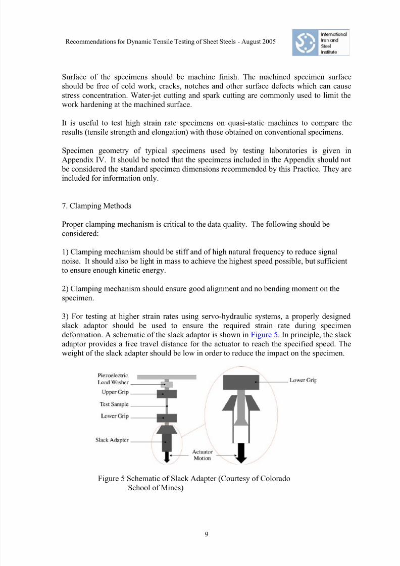
3) For testing at higher strain rates using servo-hydraulic systems, a properly designed
slack adaptor should be used to ensure the required strain rate during specimen
deformation. A schematic of the slack adaptor is shown in Figure 5. In principle, the slack
adaptor provides a free travel distance for the actuator to reach the specified speed. The
weight of the slack adapter should be low in order to reduce the impact on the specimen.
Figure 5 Schematic of Slack Adapter (Courtesy of Colorado
School of Mines)

8/11/2019 High Strain Rate Testing Recommended Practice (1)
http://slidepdf.com/reader/full/high-strain-rate-testing-recommended-practice-1 12/30
Recommendations for Dynamic Tensile Testing of Sheet Steels - August 2005
10
4) For testing at strain rates higher than 500/s using bar techniques, either Split
Hopkinson Bar (SHB) or Single Bar method, clamping fixtures are mounted directly to
the input bars. It is recommended that the clamping fixture uses the same material as theinput bar and of the same diameter to ensure the least impedance change when the stress
wave propagates through the loading train. If different material or size is used, proper
adjustment should be made in the calculation of the stress and strain.
8. Measurement Devices
Strain measurement
Strain in tensile tests is represented by the ratio between the relative displacement of two
points in the gauge section, i.e. gauge length, of a specimen and their initial distance,engineering strain. Generally, an extensometer attached to the gauge section of the
specimen is used and the measurement is very accurate. At higher strain rates, it is almost
impossible to use this method due to inertia effects of the extensometer. Thus, strain
measurement at high strain rates usually uses the relative displacement of the points
selected from the place other than the gauge section of the specimen, for example, the
displacement between grips of the specimen or the displacement of the actuator measured
by LVDT.
When the strain is not measured directly from the gauge section of the specimen, special
attention should be paid to assure the dominant deformation in the gauge section of the
specimen. The deformation in the remaining sections of the loading train falsely increasesthe strain measured and normally gives incorrect and much lower initial slope of the
stress-strain curve in the elastic region.
The following devices can be used to measure strain. Because many of the measurement
devices are still in the development stage, the quality of the measurement devices varies
significantly by different manufacturers. Cautions must be taken to ensure quality of
testing results.
1. Conventional low inertia extensometer can be used for strain rates up to 10/s.
2. Strain gauges for large strain measurement attached to the gauge section of thespecimens can be used for strain measurement. The maximum strain is limited by the
commercial strain gauges available, normally around 10% . At present, using strain
gauge is the best method to record stress strain data at small strain regions when yield
strength and yield point elongation is of interest. However, due to the increased time
and equipment needed, it should only be applied in special cases or for base research
investigations To compensate for the coil set, strain gauges may be attached on both
surfaces of the specimen.
3. An Electro-optical, Doppler or laser extensometer of good quality is highly
recommended for strain rates up to 103/s. The device is capable of recording strains
throughout the test.

8/11/2019 High Strain Rate Testing Recommended Practice (1)
http://slidepdf.com/reader/full/high-strain-rate-testing-recommended-practice-1 13/30
Recommendations for Dynamic Tensile Testing of Sheet Steels - August 2005
11
4. Displacement measured by LVDT can be used to calculate strain using the following
formula:
L
L∆=ε
where ε is engineering strain, L is the initial parallel length of the specimen and ∆L is
the displacement as measured by LVDT and corrected for machine stiffness. This
formula can provide sufficiently good strain measurement only when the deformation
in the parallel section is dominant, and that in the remaining sections of the loading
train is negligible comparing with the deformation in the reference section.
In general, LVDT is not recommended as the sole device for strain measurement. Itcan be used to provide back up data for other measurement devices. When no other
devices are available, using displacement measurement by LVDT in combination with
attaching strain gauges in the gauge section to measure small strains can offer
satisfactory strain measurement for the full strain region.
5. For bar type system, strain gauges attached to the bars are used for strain
measurement. The displacement of bar / specimen interfaces can be obtained by the
signals measured by the strain gauges based on an analysis of the propagation of the
elastic waves in the bars. This method is capable of recording strains throughout the
test.
6. A constant nominal strain rate throughout the test is essential to the quality of data.
The strain rate must be calculated during the test to insure that a constant rate is
achieved.
7. Fracture elongation of the specimens should also be determined manually after the
test to verify the strain measurement.
Stress measurement
Stress signal from dynamic testing often exhibits significant oscillation due to ringing of
the loading system at high strain rates. To reduce the stress oscillation, besides careful
designs of testing machine, clamping system and specimen, proper selection of the load
measurement device is critical. Load measurement devices should be close to the
specimen as possible in order to reduce the phase difference between the strain
measurement and stress measurement.
In general, stress can be measured in the following two ways:
1. Measure the load, P, by using a commercial load cell and calculated the engineering
stress by σ = P/S, where S is the initial area of the cross section.

8/11/2019 High Strain Rate Testing Recommended Practice (1)
http://slidepdf.com/reader/full/high-strain-rate-testing-recommended-practice-1 14/30
Recommendations for Dynamic Tensile Testing of Sheet Steels - August 2005
12
2. Measure the engineering elastic strain, εe, by attaching strain gauges (elastic) on the
location outside the gauge section of the specimen where the deformation is elastic.
Load is calculated by using the Young's modulus, i.e. P = εe *E*S. The location ofthe strain gauges can be in the grip section of the specimen, or in a separate specially
designed grip [6, 7].
Whichever system is used, careful calibration is important to ensure accurate stress
measurement. Especially, when the method (2) is used, strain gauges attached on the
specimen shall be calibrated for each specimen. Load measuring errors are introduced if
every specimen is not calibrated. The following devices are recommended:
1. Conventional strain gauge instrumented load cell is used for strain rates up to 10/s.
2. Piezo-electric load washer is used for <100/s
3. Load measurement by strain gauges:• When strain gauges are attached to the grip section of the specimen, one strain
gauge on each side of specimen is preferred to compensate the effect of coil set.
• When strain gauges are attached to a separate grip, careful design of the grip is
imperative to ensure sufficient load range, minimum noise, and good
measurement repeatability and reliability.
• In the servo-hydraulic system, the section where strain gauges attach should not
be mounted to the actuator where acceleration applies.
• For bar systems, stress is calculated by using the strain measured from the strain
gauge attached to the transmitter/output bar. The location of the strain gauge
should be such that the stress measurement is completed before the transmitted
stress wave reflected back from the other end of the transmitter/output bar (seeAppendices I and II).
In addition to stress oscillation originated at stress measurement devices, there is
inevitable elastic response of the tested materials due to a sudden loading. The
characteristic might be represented by a rise time of a load signal. In actual testing system,
there exists a fairly long rise time, thus the oscillation of this origin does not cause any
significant effects on the measured signals. For example, in the split Hopkinson bar
method the incident wave is partially dispersed during its propagation in the incident bar
and shows a relatively long rise time. Damping to reduce such oscillation should be used
very carefully. Too much damping limits the strain rate at the beginning of the
deformation and changes the apparent material behavior. If damping methods must be
applied, the information of strain rate versus strain becomes indispensable. This is
schematically shown in Figure 6. As seen in Figure 6, if the strain range of interest is
greater than 10%, damping may be acceptable, but if the strain range of interest is less
than 10% damping is not acceptable.

8/11/2019 High Strain Rate Testing Recommended Practice (1)
http://slidepdf.com/reader/full/high-strain-rate-testing-recommended-practice-1 15/30
Recommendations for Dynamic Tensile Testing of Sheet Steels - August 2005
13
Figure 6. Effect of damping on strain rate (schematic)

8/11/2019 High Strain Rate Testing Recommended Practice (1)
http://slidepdf.com/reader/full/high-strain-rate-testing-recommended-practice-1 16/30
Recommendations for Dynamic Tensile Testing of Sheet Steels - August 2005
14
9. Assessment and Improvement of Data Quality
Load oscillation in the stress strain curve is one of the major quality issues for dynamictesting. Figure 7 shows engineering stress strain curves measured at 100/s and 500/s on a
servo-hydraulic system. Notice not only the oscillation of the load becomes severe at
500/s, the engineering stresses at strains below 15% also increase much more than in the
higher strain region. The drastic increase of flow stress at the low strain region may be the
effect of initial impact of the actuator. It is therefore very important to assure that the
stress oscillation is limited and the change of the shape of the stress strain curve is fully
understood. The experiences for several testing laboratories show that using strain
gauges attached to the specimen grip section can significantly reduce load oscillation as
shown in Figure 8 when a piezo-electric load washer is replaced by strain gauges at the
grip section of the specimen.
0
100
200
300
400
500
600
700
800
900
0 0.1 0.2 0.3 0.4 0.5
Engineering Strain
E n g i n e e r i n g S t r e s s ( M P a )
100/s
500/s
Figure 7 Engineering stress-strain curve at
100/s and 500/s. (Courtesy of Ispat
Inland Inc.)

8/11/2019 High Strain Rate Testing Recommended Practice (1)
http://slidepdf.com/reader/full/high-strain-rate-testing-recommended-practice-1 17/30
Recommendations for Dynamic Tensile Testing of Sheet Steels - August 2005
15
0
200
400
600
800
1000
1200
0 10 20 30 40 50
Strain (%)
S t r e s s ( M P a )
Strain resistor
gauge Signal
Piezo-Signal
Figure 8 Improvement of engineering stress-strain curve using
strain gauges at the grip section of the specimen (strain
rate 500s-1)
Incorrect slope of the stress strain curve in the elastic region is another quality issue for
dynamic testing results. The slope is often much lower than the Young's modulus. Asdiscussed in Section 8, the origin of lower slope lies in the accuracy of the strain
measurement. When a strain gauge is attached to the gauge section of the specimen, the
strain measured normally offers the best linear section of the stress strain curve. Proper
specimen design and measurement setting would offer fairly good results when other
strain measurement techniques are used.
Continuous improvement of data quality requires holistic approach by investigating the
testing system, clamping mechanism, specimen design and measurement devices. An
example of eliminating the false upper yield point by carefully eliminating the
microvibration of the output bar for a Single Bar system is shown in Appendix V.
Generating quality data often incurs significantly more testing work and higher cost. For
example, adding strain gauges for both strain and stress measurements will not only add
the equipment needed for data acquisition and the number of consumable strain gauges,
but also significantly add test preparation time and thus reduced productivity. Depending
on the purpose of testing and the amount of work load, balance between quality, cost and
efficiency must be evaluated properly.

8/11/2019 High Strain Rate Testing Recommended Practice (1)
http://slidepdf.com/reader/full/high-strain-rate-testing-recommended-practice-1 18/30
Recommendations for Dynamic Tensile Testing of Sheet Steels - August 2005
16
REFERENCES
1. Tensile Testing Standards at Quasi-Static Conditions: ASTM E6 (American Society for Testing and Materials) Standard Terminology
Relating to Methods of Mechanical Testing
ASTM E8 (American Society for Testing and Materials) Test Methods for
Tension Testing of Metallic Materials
ASTM E74 (American Society for Testing and Materials) Practice of Calibration
of Force-Measuring Instruments for Verifying the Force Indication of Testing
Machines
B 0801 (Korean Standards Association) Test Pieces for Tensile Test for Metallic
Materials
B 5518 (Korean Standards Association) Extensometers Used in Metallic Material
Tensile Testing
B 5521 (Korean Standards Association) Tensile Testing Machines
AS 1391 (Standards Australia) Methods for Tensile Testing of Metals Amdt 1
May 1992; ISO 6892: 1984
EN 10002-1 (European Committee for Standardization) Metallic Materials -
Tensile Testing - Part 1: Method of Test at Ambient Temperature SDO Approval
Date: 2001-07-00
EN 10002-2 (European Committee for Standardization) Metallic Materials -
Tensile Testing - Part 2: Verification of the Force Measuring System of the
Tensile Testing Machines SDO Approval Date: 1991-00-00
EN 10002-3 (European Committee for Standardization) Metallic Materials -
Tensile Test - Part 3: Calibration of Force Proving Instruments Used for the
Verification of Uniaxial Testing Machines SDO Approval Date: 1991-00-00
EN 10002-4 (European Committee for Standardization) Metallic Materials -
Tensile Test - Part 4: Verification of Extensometers Used in Uniaxial Testing
SDO Approval Date: 1994-00-00
ISO 6892:1998 (International Organization for Standardization) Metallic materials
-- Tensile testing at ambient temperature
JIS Z 2241:1998 (Japanese Standards Association) Method of tensile test for
metallic materials
JIS Z 2201:1998 (Japanese Standards Association) Test pieces for tensile test for
metallic materials
2. B. Hopkinson, "A Method of Measuring the Pressure Produced in the Detonation of
Explosives or by the Impact of Bullets", Phil. Trans. A, 213, 1914, p. 437

8/11/2019 High Strain Rate Testing Recommended Practice (1)
http://slidepdf.com/reader/full/high-strain-rate-testing-recommended-practice-1 19/30
Recommendations for Dynamic Tensile Testing of Sheet Steels - August 2005
17
3. R. M. Davies, "A Critical Study of the Hopkinson Pressure Bar", Phil. Trans. A, 240,
1948, p. 375
4. H. Kolsky, "An Investigation of the Mechanical Properties of Materials at Very HighRates of Loading", Proc. Royal Soc. B, 62, 1949, p. 676
5. Kawata et al. "On High-velocity Brittleness and Ductility of Dual Phase Steel and
Some Hybrid Fiber reinforced Plastics", in "Recent Advances in composites in the
United States and Japan", ASTM STP 864, Am. Soc. For Testing and Materials,
Philadelphia, 1985, P. 700
6. T. Bollinghause and W. Bleck, "Determination of Crash-Relevant Material Properties
by Dynamic Tensile Tests", 44th MWSP Conference Proceedings, ISS, 2002, pp. 483-
491
7. S. Tanimura, K. Mimura, and T. Umeda, "New Testing Techniques to Obtain Tensile
Stress-Strain Curves for a Wide Range of Strain Rates", presented at DYMAT, Porto,
Portugal, Sept. 8-12, 2003

8/11/2019 High Strain Rate Testing Recommended Practice (1)
http://slidepdf.com/reader/full/high-strain-rate-testing-recommended-practice-1 20/30
Recommendations for Dynamic Tensile Testing of Sheet Steels - August 2005
18
Appendix I
Tension Split Hopkinson Bar (University of Dayton Research Institute)
1. Machine Capacity and Major Specifications
DTSHB configuration has been routinely employed in our laboratory to
characterize tensile behavior of various grades of automotive sheet steels at strain rates
from 200-1500/s over the last 3 years. Incident and transmitting bars of the DTSHB are
made of 2.44-m (8 feet) long 25.4-mm diameter 7075 aluminum (Fig. 1). Two (1000 Ω)
strain gauges are mounted on each bar 48-inches away from the specimen to monitor
strains in the pressure bars. A 0.76-m long aluminum striker tube is generally launched
around the incident bar and the impact of the aluminum tube against the aluminum anvil(rigidly attached to the end of the incident bar) generates a tensile stress pulse in the
incident bar (Fig. 1). We also have aluminum striker tubes of shorter lengths for shorter
loading pulse. For materials with extremely low tensile strength Nylatron
(Nylon/Graphite composite) striker tubes are recommended to produce low amplitude
incident tensile pulses.
Figure 1. Schematic of the Direct Tension Split Hopkinson Bar
2. Specimen: Size (Dimensions) and Fabrication
Tension specimens of automotive sheet steels are generally dog-bone shaped (e.g.,
ASTM D 1822 Type L, Fig. 2) and are fabricated either in our machine shop or using
water jet cutting technique (RPG Industries, Tipp City). These are placed in specially
designed grips screwed into the threaded incident and transmitting aluminum bars.
Tension specimens with threaded ends (Fig. 3), generally fabricated from 6.35-mm
diameter bar stock or 6.35-mm thick sheet stock can also be tested. To accept the
threaded specimen, aluminum anvils are attached to the incident and transmitting bar endswith threaded holes. We also have a capability of tensile characterization of different
I nc ident Bar Transmi t t e r Bar
G r i pS t r a in G a u g e
S p e c i m e nSt r iker Tube
F l a t D o g B o n e S p e c i m e n

8/11/2019 High Strain Rate Testing Recommended Practice (1)
http://slidepdf.com/reader/full/high-strain-rate-testing-recommended-practice-1 21/30
Recommendations for Dynamic Tensile Testing of Sheet Steels - August 2005
19
materials available in 6.35-mm diameter bar stock or 6.35-mm thick sheet stock (threaded
specimens) using our 12.5-mm diameter Indirect Tensile Hopkinson (Inconel) Bar
configuration. This SHB configuration allows the tensile testing to be conducted at hightemperatures to 1200oF.
Figure 2. ASTM D1822 Type L Tension Specimen
Figure 3. Threaded tensile specimen fabricated from 6.35-mm diameter
bar or 6.35-mm thick sheet stock
3. Measurement Method
A tensile stress pulse is generated in the incident bar by the impact of the striker
tube with the flange at the end of the incident bar. This tensile pulse propagates towards
the incident bar/specimen interface and subjects the specimen to a tensile load. A portion
of this incident tensile pulse, εi, is transmitted through the specimen εt and the remainder
is reflected back in the incident bar εr . The amplitude of the incident, reflected, and
transmitted pulses are recorded by the strain gauges mounted on the pressure bars.
Incident, reflected, and transmitted stress pulse data are analyzed following the procedure
given below.

8/11/2019 High Strain Rate Testing Recommended Practice (1)
http://slidepdf.com/reader/full/high-strain-rate-testing-recommended-practice-1 22/30
Recommendations for Dynamic Tensile Testing of Sheet Steels - August 2005
20
Using the recorded strains, the stress (σ), strain (ε) and strain rate ( &ε ) in the
specimen are determined using Equations (1-3)
where A b and As are the cross-sectional area of the pressure bar and the specimen in the
gauge section, respectively, and L is the gauge length of the specimen. The stress, strain,
and strain rate are the average values and are determined by assuming a uniform uniaxial
stress-state condition, which implies that
t ir ε ε ε −=− (4)
The strain rate in an experiment (Equation 3) depends on the magnitude of the
reflected pulse εr , which is a function of the magnitude of the incident pulse εi and that of
the transmitted pulse εt. The magnitude of the transmitted pulse is bounded by the flow
stress of the material, as given by Equation (1). Assuming that the compressive strength
of the material is constant, the magnitude of εr depends on the magnitude of εi only. Thus,the specimen strain rate is directly related to εi, which is given by:
ε ρ i o s E
C V =⋅
⋅ ⋅1
2 (5)
where Vs is the striker bar velocity. Consequently, one way of changing the specimen
strain rate is to change the striker bar velocity. An alternative way to change the
specimen strain rate is change the specimen gauge length. In fact, the flow stress of the
material is not constant, but is a function of the strain rate and temperature. Therefore, a
fine adjustment in the striker tube velocity is always needed to achieve the predeterminedstrain rate.
)()( t A
A E t t
s
bε σ = (1)
∫⋅
−=t
r o dt t
L
C t
0
)(2
)( ε ε (2)
)(2
)( t L
C t
r o
ε ε ⋅
−=& (3)

8/11/2019 High Strain Rate Testing Recommended Practice (1)
http://slidepdf.com/reader/full/high-strain-rate-testing-recommended-practice-1 23/30
Recommendations for Dynamic Tensile Testing of Sheet Steels - August 2005
21
Appendix II
One Bar Method (Nippon Steel Corporation)
One-bar technique has been developed by Kawata et al. (On high-velocity brittleness and
ductility of dual-phase steel and some hybrid fiber reinforced plastics, Recent advances in
composites in the United States and Japan, ASTM STP 864, Am. Soc. for Testing and
Materials, Philadelphia, 700., 1985), based on the Hopkinson bar method. As shown in
Figure 1, the testing system consists of a hammer, an impact block, a specimen and an
output bar. When the impact block is given an impact by the hammer, the specimen is
deformed in tension. At the instant of the impact, a transmitted wave starts to propagate in
the output bar, its amplitude being proportional to the stress in the specimen. This wave is
recorded by a strain gauge attached to the output bar at section C, situated at a distance a from section B. In addition, an electro-optical extensometer is used to measure the
velocity V (t ) of the impact block, which is integrated to give the displacement of section
A
( )0
t
Au V t dt = ∫ . (1)
An analysis of the propagation of the elastic waves in a bar enables to derive the
displacement uB of section B, from the strain of the transmitted waveg( )t ε at section C.
The propagation of waves in a bar is considered as a one-dimensional problem, when the
lateral inertia can be neglected. Considering the delay of the wave propagation, uB can beexpressed in terms of
gε as
B B g0 0
( ) = ( )t t
u c t dt c t a c dt = ε ε +∫ ∫ . (2)
The elongation of the specimen is the difference between the displacements at
sections A and B. By using Eqs. (1) and (2) the engineering strain and the engineering
strain rate of the specimen may be expressed as
( )
A B
g00 0
1e( ) ( ) ,
t u ut V c a c d
L L
−⎡ ⎤= = τ − ε τ + τ⎣ ⎦∫
(3)
g
0
1e( ) ( ) ( ) ,t V t c t a c
L⎡ ⎤= − ε +⎣ ⎦& (4)
where L0 is the length of the specimen. The axial force F (t ) at section B can also be
determined from the amplitude of the transmitted waveg( )t ε as
bar bar B bar bar g( ) ( ) ( ).F t E A t E A t a c= ε = ε + (5)

8/11/2019 High Strain Rate Testing Recommended Practice (1)
http://slidepdf.com/reader/full/high-strain-rate-testing-recommended-practice-1 24/30
Recommendations for Dynamic Tensile Testing of Sheet Steels - August 2005
22
Thus, the nominal stress in the specimen becomes
bar bar n g
0 0
( )( ) ( ).
A E F t t t a c
A Aσ = = ε + (6)
Figure 1 Schematics of one bar method high strain rate tensile test machine

8/11/2019 High Strain Rate Testing Recommended Practice (1)
http://slidepdf.com/reader/full/high-strain-rate-testing-recommended-practice-1 25/30
Recommendations for Dynamic Tensile Testing of Sheet Steels - August 2005
23
0
100
200
300
400
500
600
700
0 10 20 30 40 50
N o m i n a l s t r e s s ( M P a )
Engineering strain (%)
0.001 s-1
0.1 s-1
1,000 s-1
Figure 2 Example of stress-strain curves measured by one bar method (1,000s-1) and
conventional method (0.001, 0.1 s-1)

8/11/2019 High Strain Rate Testing Recommended Practice (1)
http://slidepdf.com/reader/full/high-strain-rate-testing-recommended-practice-1 26/30
Recommendations for Dynamic Tensile Testing of Sheet Steels - August 2005
24
Appendix III
Calculation of Strain Limit for SHB System
The duration of the stress pulse going through the specimen in a Split Hopkinson Bar
system is dependent on the length of the striker bar and thus is fixed for a test machine.
In general, the duration of the stress pulse can be expressed as follows for a system in
Figure 3,
0
2
C
lT s=
where ls is the length of the striker tube, ρ
E C =0 , and T is the transition time, or the
duration of the stress pulse. E and ρ are the Young's modulus and density of the striker
tube, respectively. For an Inconel striker bar of 0.76m long, for example, T can be
calculated to be 315 µs.
The total strain of the steel specimen achieved during this time duration is proportional to
the strain rate,
ε ε &∗= T total
When the strain rates is high, the total strain achievable can be higher than the total
elongation of the steel. However, if the strain rate is low, the total strain achievable can be
lower than the total elongation of the steel, meaning the duration of the stress wave is not
long enough to break the specimen. The minimum strain rate for a SHB system is thus
dependent on the strain required for the steel. Normally, uniform elongation is the
minimum strain required for a meaningful tensile test at high strain rates. The minimum
strain rate for a SHB system can be estimated as
T
UE =
minε &
where UE is the uniform elongation of the steel.

8/11/2019 High Strain Rate Testing Recommended Practice (1)
http://slidepdf.com/reader/full/high-strain-rate-testing-recommended-practice-1 27/30
Recommendations for Dynamic Tensile Testing of Sheet Steels - August 2005
25
Appendix IV
Examples of Specimen Geometry
It should be noted that the specimens included in the Appendix should not be considered
the standard specimen dimensions recommended by this Practice. They are included for
information only.
Figure 1 Specimen used by UDRI
Figure 2 Specimen used by JFE
Figure 3 Specimen used by Sumitomo Metals

8/11/2019 High Strain Rate Testing Recommended Practice (1)
http://slidepdf.com/reader/full/high-strain-rate-testing-recommended-practice-1 28/30
Recommendations for Dynamic Tensile Testing of Sheet Steels - August 2005
26
Figure 4 Specimen used by Nippon Steel Corporation
Figure 5 Specimen used by Nippon Steel Corporation
Figure 6 Specimen used by Technical University of Aachen
Figure 7 Specimen used by Technical University of Aachen

8/11/2019 High Strain Rate Testing Recommended Practice (1)
http://slidepdf.com/reader/full/high-strain-rate-testing-recommended-practice-1 29/30
Recommendations for Dynamic Tensile Testing of Sheet Steels - August 2005
27
Figure 8 Specimen used by Arcelor
Figure 9 Specimen used by Arcelor
Figure 10 Specimen used by ThyssenKrupp Stahl

8/11/2019 High Strain Rate Testing Recommended Practice (1)
http://slidepdf.com/reader/full/high-strain-rate-testing-recommended-practice-1 30/30
Recommendations for Dynamic Tensile Testing of Sheet Steels - August 2005
Appendix V
Improvement of Data Quality for One Bar Method (Nippon Steel Corporation)
Phenomena
In many cases, , initial peaks around yield point are recorded during tensile tests at
high strain rates.
Origins
Pseudo initial peaks are caused by micro-vibrations of the output bar at the
interface with the specimen. They are possibly induced by the bending of the output
bar by gravity and/or the misalignment of the impact block along the tensile
direction.
Improved configurations of the test systemThe alignment of the output bar, the specimen and the impact block should be
strictly kept along the tensile direction. In addition, it was shown that jigs near the
interface between the bar and the specimen can prevent efficiently micro-vibrations
of the bar.
JJiiggss
ttoo r r eedduuccee vviibbr r aattiioonnss
Output bar Impact Block
Specimen
0.0001 0.0003 0.0005 0.00
200
400
600
N o m i n a l s t r e s s
( M P a )
Time (s)
previous method
improved method
Conclusions
The alignment of the output bar, the specimen and the impact block along the
tensile direction is important. Stress-strain curves measured by the improved
machine configuration are free from pseudo initial peaks.