
High quality hinge with integrated dampening. … Mounting plates are available for securing with...
21
Technik für Möbel High quality hinge with integrated dampening. Sensys.
Transcript of High quality hinge with integrated dampening. … Mounting plates are available for securing with...

Technik für Möbel
High quality hinge with integrated dampening.Sensys.
Technik für Möbel
High quality hinge with integrated dampening.Sensys.
Technik für Möbel
Perfected hinge design for the last word in softened closure. Sensys
11739_Sensys_Katalog_1011.indd 1 05.06.12 12:43

3
Sensys.Perfect design, perfect action
Hettich´s fi rst hinge with integrated dampening
Sensys marks the latest generation in hinge technology: The dampening element is integrated invisibly into the hinge – an innovation that meets the highest criteria for convenience and functionality. Just a light touch – and the door closes smoothly and silently. The unique pull-in function closes the door gently and automatically as soon as the open angle is less than 35°. Sensys delivers an exclusive closing experience. Sensys incorporates high quality material and perfect ´Silent System´ soft closing action - without the need for bulky adaptors.
Clean, elegant design
Sensys has an elegant, contemporary look and meets all customer expectations for outstanding design and quality. The simple, sleek, harmoni-ous lines of the design – from the cup and the arm cover cap to the mounting plate – give the hinge its streamline modern look. All edges and radii contribute to the perfect harmony of hinge and mounting plate. Silent System dampening is integrated invisibly in the hinge, as is the unlatch tab. Specially designed cover caps conceal fi xing screws and adaptors. Winner of zhe 2008 reddot Design Award and the 2009 iF Product Design Award, Sensys seamlessly combines aesthetics and function.
2

5
Toolless assembly
Sensys hinges are mounted and removed quickly and easily. No tools are required. It is unlatched from the hinge arm in one smooth, ergonomic movement by lightly pressing the concealed latch.
Engineered for easy use
With its shallow cup depth, Sensys is a versatile solution for many applications, for example, with thinner doors or bigger outside radii. The Sensys hinge design also permits minimal visible reveals currently popular even with thick doors. The direct adjustment feature makes it easy to set door depth. A special guard prevents accidental disengagement of the overlay adjustment screw. Cam screws in the mounting plate allow fast door height adjustment.
Sensys is a low, slimline design; it leaves ample space for internal drawers, so that only very narrow gaps need be planned between the side panels and drawers.
Sensys stands for tested quality, compliance with all current standards, excellent dampening performance, durability and high stability. Sensys meets the highest design criteria and is sure to be a long-time favourite.
4
Sensys.Engineered for easy use

7
Mounting plates are available for securing with various options – expanding sockets, pre-mounted with Euro screws and the Hettich Top with eccentric height adjustment.
6
Wide product range
The Sensys hinge family includes products for all popular door mounting options, so that Sensys hinges can be used in a wide variety of cabinet designs. Designed-in compatibility means that Sensys mounting plates can also be combined with hinges from the Intermat range.
Sensys.Versatile for different applications
Sensys cups and mounting plates can be mounted using any of the commonly accepted methods. The cup can be secured in place by screws, knock-in sockets or by toolless Fix fast assembly.
76
Broad product range
The Sensys range provides hinges for all popular mounting options, making it possible to fit Sensys to cabinets of many different designs. The compatibility of Sensys mounting plates means they can also be combined with hinges from the Intermat range.
SensysVersatility for a wealth of applications
Mounting plates are available for attachment by means of screws, press-in or expanding sockets, premounted Euro screws or using the patented Hettich Direkt system.
Sensys cups and mounting plates are designed for attachment in a variety of ways. Depending on the type of fabrication, the cup can be mounted using screws, press-in sockets or by toolless Fix fast assembly.
11739_Sensys_Katalog_1011.indd 6-7 05.06.12 12:44

9
Integrated overlay adjustment ± 2 mm with stop limitation for perfect gap alignment
Hinge and mounting plate - a perfect design match
Mounting plate compatible with Intermat hinge range
Eccentric height adjustment ± 2 mm saves an enormous amount of time
Unique self-closing angleGentle, smooth closing from an opening angle of 35°
Narrow revealsOnly 4 mm for 22 mm door thickness
Minimum door protrusionNarrow gaps maximize space available for internal drawers
Toolless assemblyPress gently and the hinge arm engages securely in the mount-ing plate
Depth adjustment + 3 / -2 mm and direct adjustment for milli-metre precision
Shallow cup depth:12,8 mm
8
Sensys.A glance at the benefi ts
Concealed release latchSimple, safe, reliable
High-performance Silent System dampening system invisibly integrated in the hinge arm
Elegant cover cap for the hinge cup

1110
Überdehntest
F
Vertikaltest
F
G
Verschleißtest
G
F
G
Zuschlagtest
Hettich and the environment: committed to responsible practice, active protection, innovative thinking.
Hettich takes a responsibility for the world we live in. This awareness defines the strict policy of environmental management we practise. Our environmental officer has taken personal responsibility for these aspects throughout the company group over a period of many years. In addition, a separate environment committee has been established for each production site. We regard statutory provisions as minimum requirements. At significant sites we also imple-ment the stringent EMAS Directive. And we drive forward developments that in future will help to save even more raw materials and support the necessary endeavours towards sustainability.
Hettich standard for product materials
Hettich underpins its commitment by applying an internal standard for product materials. This ensures that every product – from production to disposal – satisfies all environmental requirements. Products from Hettich come with a long life. Appropriately foresighted, our rigorous standards are formulated to ensure that international legislation is met as well. This provides a reliable basis for marketing furniture world-wide.
Hettich environmental management
Hettich started introducing effective environmental man-agement systems under the stringent EMAS Regulation (currently: EC Regulation No. 761/2001, including EN ISO 14.001/2004) as long ago as 1996. This not only enables us to improve our environmental performance on a broad front but also achieve a high level of safety which, not least, also benefits our customers. This is why we also require our suppliers to meet the necessary minimum standards of environmental protection, industrial safety, health care and social welfare. The results achieved in the drawer-runner and drawer-system product segment at the Kirchlengern operation illustrate the impressive effects these measures have and verifiably demonstrate our tireless endeavours to translate words into action:
Relief to the environment between 1997 and 2008:
Specific water consumption: 56 per centSpecific power consumption: 21 per centSpecific heat consumption: 84 per centSpecific CO2 emissions: 29 per cent
Hinges with integrated soft-closing mecha-nism are constantly monitored for quality. The varying quality standards demanded by different markets and segments are each taken into account. The diagrams show examples of some of the testing processes and what they involve.
Horizontal testIn this test, also referred to as the overstraining test, the door is over-opened with a defined test force F.
Life cycle testThe door must withstand a defined number of opening and closing cycles with a defined additional load G.
Closing testThe door is opened by 30° with a defined additional load of G and pushed closed from this position by means of the falling weight.
Quality criteria
· Life cycle test over 80,000 cycles
· Closing test with an additional weight of 4 kg
· Load test in horizontal direction with 40 N
· Load test in vertical direction with 200 N
Sensys Quality that meets all of demands
Vertical testThis is where the door is subjected to a specific number of opening and closing cycles under a defined additional load G.
11739_Sensys_Katalog_1011.indd 10-11 05.06.12 12:45

1312
Product overview: fast-assembly concealed hinges Sensys with integrated soft-closing function and supplementary Intermat range
Technical information
14 - 17
Sensys 8645i
Opening angle 110° for doors up to 22 mm thickness
18 - 19
Sensys 8639i
Opening angle 95° for doors up to 28 mm thickness
20 - 21
Sensys 8639i W30
Opening angle 95° for 30° face angle applications
22 - 23
Sensys 8639i W45
Opening angle 95° for 45° face angle applications
24 - 25
Sensys 8639i W90
Opening angle 95° for 90° face angle applications
26 - 27
Sensys 8638i
Opening angle 95° for aluminium framed doors
28 - 29
Intermat 9956
Opening angle 165°
32 - 33
Intermat 9930
Opening angle 50°/65° for corner cabinet folding doors
34 - 35
Accessories
37 - 39
System 8099 mounting plates
for Sensys and Intermat hinges
36
On request also without soft-closing element, within the article mix with damped hinges.
11739_Sensys_Katalog_1011.indd 12-13 05.06.12 12:45

1514
5
4
3
2
X
C
(-) (+) (+)
(-)
(+)
(-)
(-)
(+)
Fast-assembly concealed hinges with integrated soft-closing function Sensys Technical information
Minimum reveal
Minimum reveal
2 x minimum reveal
Mounting options
The minimum reveal (also known as door clearance or minimum clearance) is the space required at the side for opening a door.The size of the minimum reveal depends on the cup distance C, the door thick-ness and the type of hinge selected. Radii on the door edges reduce the minimum clearance.The required minimum reveal is shown in the table for the respective hinge types.
For half-overlay applications, the total reveal selected between the doors must be at least twice the door clearance. Both doors can then be opened at the same time.
Minimum reveal Minimum reveal at centre panel
Inset applicationThe door is positioned inside the cabinet, i.e. next to the cabinet side. Here too, a gap is needed so that the door can open reliably. Heavily cranked hinges (Basis B = - 4 mm) are used.
Half-overlay applicationThis is where two doors are positioned in front of a cabinet centre panel, with the required overall reveal between them.In other words, the door has a smaller over-lay and cranked hinges (Basis B = 3 mm) are used.
Overlay applicationThe door is positioned in front of the cabi-net side, with only a small gap remaining at the side to provide the space necessary for door to open reliably. Alternatively, the door can be overlaid fully (max. 19 mm), in which case sufficient space must be allowed at the side for the required minimum reveal. Straight hinges (Basis B = 12.5 mm) are used.
up t
o 20
00
Door
hei
ghts
Number of hinges per door:Door width, height and weight as well as the material quali-ty of the door are key factors that determine the number of hinges required. The factors encountered in practice differ widely from case to case. For this reason, the number of hinges specified in the diagram must be understood as a guide only. If in doubt, it is recommended to carry out a trial door mounting and adjust the number of hinges as necessary. For reasons of stability, distance X between the hinges must always be made as large as possible.
Cup distance CCup distance C is the distance between door edge and the edge of the cup drilling. The greater the distance selected for cup distance C, the smaller door clear-ance will be, i.e. the minimum reveal required.
Overlay (door overlay) / basis
Overlay refers to the projection of the door in front of the cabinet side. Basis refers to the projection of the cup in front of the cabinet side for a moun-ting-plate distance of 0 mm.
Overlay ABasis B
Door width up to 600 mm
up t
o 90
0up
to
1600up
to
2400
(Guide values for 19 mm chipboard panels in a density of 750 kg/m3)
at le
ast
90 m
m
Cup distance Door thickness mm C mm 15 16 17 18 19 20 21 22 Distance D mm3 0.1 0.4 0.9 1.6 4 0.3 0.5 0.6 0.8 1.0 1.3 1.7 2.3 5 1.3 1.4 1.6 1.8 2.0 2.3 2.6 3.1 6 2.3 2.4 2.6 2.8 3.0 3.2 3.6 3.9
Depth adjustment Height adjustmentOverlay adjustment
General determination of distancesMounting plates are available in various distances (0/1.5/3 and 5 mm). The effective height of the mounting plate is defined by distance D. Distance D is embossed on the top of each mounting plate. A larger distance D reduces overlay for full and half-overlay applications. On inset doors, a larger distance D increases the door reveal.To calculate the required distance, the minimum re-veal must first be determined from the table of mini-mum door reveals for the type of hinge concerned. The minimum reveal depends on the cup distance C and the door thickness. Minimum reveals can be re-duced by increasing the cup distance C and/or app-lying radii to the door edges. The table of minimum door reveals also shows the possible combinations of door thickness and cup distance C.
Calculating distance for inset doorsWhen calculating the mounting-plate distance using the table for inset doors, allowance is automatically made for the reveal that is shown as the minimum reveal produced by cup distance C and door thickness in the table of minimum reveals.If a reveal is to be produced that is larger than this minimum reveal, select a mounting-plate distance of the appropriate size.Example: According to the table, a door thickness = 19 mm and cup distance C = 6 mm produces a mounting-plate distance of 3 mm. This demands a minimum reveal of 1 mm. If, for example, a reveal of 3 mm is preferred instead, the mounting-plate distance selected must be 2 mm larger. In this example, therefore, a distance of 5 mm instead of 3 mm.Intermediate distances not available as mounting-plate distances are achieved by adjusting the hinge overlay.
Direct, infinitely variable depth adjustment
Turn screw clockwise: Door overlay is reduced (-). Turn screw anti-clockwise: Door overlay increases (+).
Height-adjustable mounting plates permit exact align-ment of door height.
Direct, infinitely variable height adjustment by eccentric screw.
Cup distance Overlay mm C mm 10 11 12 13 14 15 16 17 18 Distance D mm3 5.5 4.5 3.5 2.5 1.5 0.5 4 6.5 5.5 4.5 3.5 2.5 1.5 0.5 5 7.5 6.5 5.5 4.5 3.5 2.5 1.5 0.5 6 8.5 7.5 6.5 5.5 4.5 3.5 2.5 1.5 0.5
Calculating distance for overlay doorsOnce the minimum reveal has been defined, the re-quired distance D can be read off in the table for the required door overlay and the required cup distance C. Ideally, door overlay and value C should be selected to produce distance D that is available as mounting plate.Example: Overlay = 16 mm and cup distance C = 5 mm produce a distance D of 1.5 mm. This distance is available as mounting plate.If the calculated distance D differs from the distan-ces available as mounting plates, the difference is compensated by means of the overlay adjustment screw on the hinge arm.Example: Door overlay = 16 mm and cup distance C = 4 mm produce a distance of 0.5 mm. When using a mounting plate with a distance = 0 mm, overlay is adjusted by - 0.5 mm.
11739_Sensys_Katalog_1011.indd 14-15 05.06.12 12:45

1716
1
23
90°
90°
12
Toolless fast assembly Toolless fast assembly is distinguished by ergo-nomic handling. To begin with, all hinges are pushed onto the mounting plate from the front �. The hinge arms are then lightly pressed onto the mounting plate so they
engage with an audible click �. The hinge arm is now securely attached to the plate at five points and with zero play. As a general rule, the hinges are clipped onto corpus from top to bottom.
Hinges are removed in the opposite order, i.e. from bottom to top. The rear part of the hinge is pressed by thumb against the mounting plate while pushing on the release catch �. The hinge arm is now lifted off the mounting plate � and the door can be removed towards the front �.
Fast-assembly concealed hinges with integrated soft-closing function Sensys Technical information
Fix toolless fast assembly Toolless assembly of the Sensys Fix hinge in the door as well as removal (which can only be done with a screwdriver for safety reasons) is illustrated in the following sequence of pictures.
Assembly
Assembly
Removal
Removal
Flash fast assembly Flash fast hinge assembly and removal merely requires the use of a standard crosshead scre-wdriver PZ 2. The socket securely
expands in the wood simply by turning the Flash screw through 90°. A symbol shows that the hinge is locked in place.
Assembly
Removal
click
11739_Sensys_Katalog_1011.indd 16-17 05.06.12 12:45

1918
H
72
T
11 13
C
5,5ø1052
ø35
C
5,5ø552
ø35
459,5
C
12,86
ø35
459,5
C
136
ø8
ø35
459,5
C
ø5
ø35
48
12,8
C
6ø35
48
12,8
C
6ø35
ø10
48
C
6ø35
ø5
52
13
C
5,5ø35
110°
Fast-assembly concealed hinge with integrated soft-closing function Sensys 8645i Opening angle 110°
· Clip-on concealed hinge with integrated soft-closing function· For door thicknesses of 15 - 22 mm· Cup diameter 35 mm· Integrated overlay adjustment of ± 2 mm· Integrated depth adjustment of + 3 mm / – 2 mm· Height adjustment at mounting plate· Cup depth 12.8 mm
Cup distance Overlay mm C mm 0.5 1.5 2.5 3.5 4.5 5.5 6.5 7.5 8.5
Distance D mm
3 5.5 4.5 3.5 2.5 1.5 0.5 4 6.5 5.5 4.5 3.5 2.5 1.5 0.5 4.5 7.0 6.0 5.0 4.0 3.0 2.0 1.0 5 7.5 6.5 5.5 4.5 3.5 2.5 1.5 0.5 6 8.5 7.5 6.5 5.5 4.5 3.5 2.5 1.5 0.5
Cup distance Door thickness mm C mm 15 16 17 18 19 20 21 22
Distance D mm
3 0.1 0.4 0.9 1.6 4 0.3 0.5 0.6 0.8 1.0 1.3 1.7 2.3 4.5 0.8 1.0 1.1 1.3 1.5 1.8 2.2 2.7 5 1.3 1.4 1.6 1.8 2.0 2.3 2.6 3.1 6 2.3 2.4 2.6 2.8 3.0 3.2 3.6 3.9
Mounting H T options mm mm
Overlay 25.0 8.5 Half overlay 31.0 18.0 Inset 38.0 25.0
Hinge protrusion H/ door protrusion T for 0 mm distance and 3 mm cup distance
Cup distance Overlay mm C mm 10 11 12 13 14 15 16 17 18
Distance D mm
3 5.5 4.5 3.5 2.5 1.5 0.5 4 6.5 5.5 4.5 3.5 2.5 1.5 0.5 4.5 7.0 6.0 5.0 4.0 3.0 2.0 1.0 5 7.5 6.5 5.5 4.5 3.5 2.5 1.5 0.5 6 8.5 7.5 6.5 5.5 4.5 3.5 2.5 1.5 0.5
Cup distance Door thickness mm C mm 15 16 17 18 19 20 21 22
Minimum reveal per door – take into account when determining distance Values shown in the table apply to doors with 0 mm radius3 0.3 0.5 0.6 0.8 1.1 1.4 1.9 2.6 4 0.3 0.5 0.6 0.8 1.0 1.3 1.7 2.3 4.5 0.3 0.5 0.6 0.8 1.0 1.3 1.7 2.2 5 0.3 0.4 0.6 0.8 1.0 1.3 1.6 2.1 6 0.3 0.4 0.6 0.8 1.0 1.2 1.6 1.9
A door thickness of 22 mm with radii, for example, reduces the minimum reveal as follows: Radius 1 mm: Values shown in table - 0.4 mm Radius 3 mm: Values shown in table - 1.0 mm
Distance D
Reveal F
Overlay A
Side
Cup distance CBasis B
Basis BCup distance C
Distance D
Distance D
Overlay A
DoorDoor
2 x reveal F
Side
Reveal FCup distance C
For technical information, see pages 14 - 17
Overlay application
Half-overlay application
Inset application
Basis B
Door
Door
Side
Door
Side
Distance D = C + B - A = cup distance C + 12.5 mm - overlay A
Distance D = C + B - A = cup distance C + 3.0 mm - overlay A
Distance D = C + B + F = cup distance C - 4.0 mm + reveal F
For hinge-arm cover cap and hinge-cup cover cap, see accessories on page 38
Cup assembly Full overlay B 12.5
Half overlay B 3
Inset B -4
PU
Screw-on: TH 52 9 071 205 9 071 206 9 071 207 200
Press-in: TH 53 9 071 208 9 071 209 9 071 210 200
Flash fast assembly: TH 54 9 071 211 9 071 212 9 071 213 200
Fix fast assembly: THS 55 9 071 220 9 071 221 9 071 222 200
With premounted Euro screws:TH 56 9 071 214 9 071 215 9 071 216 200
Screw-on: TB 52 9 071 223 9 071 224 9 071 225 200
Press-in: TB 53 9 071 226 9 071 227 9 071 228 200
Flash fast assembly: TB 54 9 071 229 9 071 230 9 071 231 200
Fix fast assembly: TB 55 9 071 238 9 071 239 9 071 240 200
With premounted Euro screws:TB 56 9 071 232 9 071 233 9 071 234 200
Screw-on: TS 52 9 071 241 9 071 242 9 071 243 200
Press-in: TS 53 9 071 244 9 071 245 9 071 246 200
Flash fast assembly: TS 54 9 071 247 9 071 248 9 071 249 200
Fix fast assembly: THS 55 9 071 220 9 071 221 9 071 222 200
With premounted Euro screws: TS 56 9 071 250 9 071 251 9 071 252 200
11739_Sensys_Katalog_1011.indd 18-19 05.06.12 12:45
For mounting plates, see page 36

2120
95°
H
72
T
52
13
C
5,5ø35
11 13
C
5,5ø1052
ø35
459,5
C
12,86
ø35
459,5
C
136
ø8
ø35
48
12,8
C
6ø35
48
12,8
C
6ø35
ø10
C
5,5ø552
ø35
459,5
C
ø5
ø35
48
C
6ø35
ø5
Cup assembly Full overlay B 12.5
Half overlay B 3
Inset B -4
PU
Screw-on: TH 52 9 084 995 9 084 996 9 084 997 200
Press-in: TH 53 9 084 998 9 084 999 9 085 000 200
Flash fast assembly: TH 54 9 085 001 9 085 002 9 085 003 200
Fix fast assembly: THS 55 9 085 103 9 085 104 9 085 105 200
With premounted Euro screws:TH 56 9 085 004 9 085 005 9 085 006 200
Screw-on: TB 52 9 085 010 9 085 011 9 085 012 200
Press-in: TB 53 9 085 013 9 085 014 9 085 015 200
Flash fast assembly: TB 54 9 085 016 9 085 017 9 085 018 200
Fix fast assembly: TB 55 9 085 106 9 085 107 9 085 108 200
With premounted Euro screws:TB 56 9 085 019 9 085 020 9 085 021 200
Screw-on: TS 52 9 085 085 9 085 086 9 085 087 200
Press-in: TS 53 9 085 088 9 085 089 9 085 090 200
Flash fast assembly: TS 54 9 085 091 9 085 092 9 085 093 200
Fix fast assembly: THS 55 9 085 103 9 085 104 9 085 105 200
With premounted Euro screws: TS 56 9 085 094 9 085 095 9 085 096 200
Fast-assembly concealed hinge with integrated soft-closing function Sensys 8639i Opening angle 95°
· Clip-on concealed hinge with integrated soft-closing function· For door thicknesses of 15 - 28 mm· Cup diameter 35 mm· Integrated overlay adjustment of ± 2 mm· Integrated depth adjustment of + 3 mm / – 2 mm· Height adjustment at mounting plate· Cup depth 12.8 mm
Cup distance Overlay mm C mm 0.5 1.5 2.5 3.5 4.5 5.5 6.5 7.5 8.5
Distance D mm
3 5.5 4.5 3.5 2.5 1.5 0.5 4 6.5 5.5 4.5 3.5 2.5 1.5 0.5 4.5 7.0 6.0 5.0 4.0 3.0 2.0 1.0 5 7.5 6.5 5.5 4.5 3.5 2.5 1.5 0.5 6 8.5 7.5 6.5 5.5 4.5 3.5 2.5 1.5 0.5
Cup distance Door thickness mm C mm 15 16 17 18 19 20 21 22 23 24 25 26 27 28
Distance D mm
3 0.1 0.4 0.9 1.6 2.4 3.3 4.2 5.1 6.0 6.9 4 0.3 0.5 0.6 0.8 1.0 1.3 1.7 2.3 3.0 3.8 4.7 5.5 6.4 7.3 4.5 0.8 1.0 1.1 1.3 1.5 1.8 2.2 2.7 3.4 4.1 5.0 5.8 6.7 7.5 5 1.3 1.4 1.6 1.8 2.0 2.3 2.6 3.1 3.7 4.4 5.2 6.0 6.9 7.7 6 2.3 2.4 2.6 2.8 3.0 3.2 3.6 3.9 4.4 5.1 5.8 6.6 7.4 8.3
Mounting H T options mm mm
Overlay 25.0 7.5 Half overlay 31.0 17.0 Inset 38.0 24.0
Cup distance Overlay mm C mm 10 11 12 13 14 15 16 17 18
Distance D mm
3 5.5 4.5 3.5 2.5 1.5 0.5 4 6.5 5.5 4.5 3.5 2.5 1.5 0.5 4.5 7.0 6.0 5.0 4.0 3.0 2.0 1.0 5 7.5 6.5 5.5 4.5 3.5 2.5 1.5 0.5 6 8.5 7.5 6.5 5.5 4.5 3.5 2.5 1.5 0.5
A door thickness of 22 mm with radii, for example, reduces the minimum reveal as follows: Radius 1 mm: Values shown in table - 0.4 mm Radius 3 mm: Values shown in table - 1.0 mm
Overlay application
Half-overlay application
Inset application
Hinge protrusion H/ door protrusion T for 0 mm distance and 3 mm cup distance
Cup distance Door thickness mm C mm 15 16 17 18 19 20 21 22 23 24 25 26 27 28
Minimum reveal per door – take into account when determining distance Values shown in the table apply to doors with 0 mm radius3 0.3 0.5 0.6 0.8 1.1 1.4 1.9 2.6 3.4 4.3 5.2 6.1 7.0 7.9 4 0.3 0.5 0.6 0.8 1.0 1.3 1.7 2.3 3.0 3.8 4.7 5.5 6.4 7.3 4.5 0.3 0.5 0.6 0.8 1.0 1.3 1.7 2.2 2.9 3.6 4.5 5.3 6.2 7.0 5 0.3 0.4 0.6 0.8 1.0 1.3 1.6 2.1 2.7 3.4 4.2 5.0 5.9 6.7 6 0.3 0.4 0.6 0.8 1.0 1.2 1.6 1.9 2.4 3.1 3.8 4.6 5.4 6.3
Distance D
Door
Reveal F
Overlay A
Side
Cup distance CBasis B
Basis BCup distance C
Distance D
Overlay A
DoorDoor
2 x reveal F
Side
Basis B
Distance DSide
Reveal F
Door
Cup distance C
Distance D = C + B - A = cup distance C + 12.5 mm - overlay A
Distance D = C + B - A = cup distance C + 3.0 mm - overlay A
Distance D = C + B + F = cup distance C - 4.0 mm + reveal F
Side
Door
For technical information, see pages 14 - 17For hinge-arm cover cap and hinge-cup cover cap, see accessories on page 38
11739_Sensys_Katalog_1011.indd 20-21 05.06.12 12:45
For mounting plates, see page 36

2322
52
13
C
5,5ø35
11 13
C
5,5ø1052
ø35
459,5
C
12,86
ø35
459,5
C
136
ø8
ø35
48
12,8
C
6ø35
48
12,8
C
6ø35
ø10
C
5,5ø552
ø35
459,5
C
ø5
ø35
48
C
6ø35
ø5
W30
95°30°
95°
30°
1922
BA
... bei D 3 mm
... bei D 1,5 mm
... bei D 0 mm
LR 37
LR 28
... Korpusseite innen bei D 5 mm
30°
1922
B
F
Cup assembly Full overlay B 2
Inset B -16
PU
Screw-on: TH 52 9 085 166 9 085 167 200
Press-in: TH 53 9 085 171 9 085 172 200
Flash fast assembly: TH 54 9 085 176 9 085 177 200
Fix fast assembly: THS 55 9 085 336 9 085 337 200
With premounted Euro screws:TH 56 9 085 181 9 085 182 200
Screw-on: TB 52 9 085 191 9 085 192 200
Press-in: TB 53 9 085 196 9 085 197 200
Flash fast assembly: TB 54 9 085 201 9 085 202 200
Fix fast assembly: TB 55 9 085 341 9 085 342 200
With premounted Euro screws:TB 56 9 085 206 9 085 207 200
Screw-on: TS 52 9 085 306 9 085 307 200
Press-in: TS 53 9 085 311 9 085 312 200
Flash fast assembly: TS 54 9 085 316 9 085 317 200
Fix fast assembly: THS 55 9 085 336 9 085 337 200
With premounted Euro screws: TS 56 9 085 321 9 085 322 200
Fast-assembly concealed hinge with integrated soft-closing function Sensys 8639i W30 for 30° face angle applications, opening angle 95°
· Clip-on concealed hinge with integrated soft-closing function· For corner cabinets with 30° face angle· For door thicknesses of 15 - 28 mm
· Integrated overlay adjustment of ± 2 mm· Integrated depth adjustment of + 3 mm / – 2 mm· Height adjustment at mounting plate· Cup depth 12.8 mm
A door thickness of 22 mm with radii, for example, reduces the minimum reveal as follows: Radius 1 mm: Values shown in table - 0.4 mm Radius 3 mm: Values shown in table - 1.0 mm
Cup distance Door thickness mm C mm 15 16 17 18 19 20 21 22 23 24 25 26 27 28
Minimum reveal per door – take into account when determining distance Values shown in the table apply to doors with 0 mm radius3 1.2 1.4 1.6 1.8 2.1 2.3 2.6 2.9 3.2 3.5 3.8 4.1 4.5 4.8 4 1.1 1.3 1.5 1.7 1.9 2.1 2.4 2.6 2.9 3.2 3.5 3.8 4.2 4.5 4.5 1.0 1.2 1.4 1.6 1.8 2.0 2.3 2.5 2.8 3.1 3.4 3.7 4.1 4.4 5 0.9 1.1 1.3 1.5 1.7 1.9 2.2 2.4 2.7 3.0 3.3 3.6 3.9 4.2 6 0.8 1.0 1.2 1.4 1.6 1.8 2.0 2.2 2.5 2.7 3.0 3.3 3.6 3.9
Note: The drawing below shows the hinges and mounting-plate distances to a scale of 1:1. By drawing in the required cup distance C (3 - 6 mm), the door overlay can be measured directly from the individual distance lines.The position for attaching the moun-ting plate is determined by measuring along the chosen distance line from the cabinet front edge to the applicable centre line.For inset-mounted doors, the minimum reveal must be selected from the table in relation to door thickness and distance C.
Overlay application Inset application
Scale 1: 1
Overlay: Distance D = 0.87 x (C + B - A) = 0.87 x (cup distance C + 2 mm - overlay A)
Inset: Distance D = 0.87 x (C + B + F) = 0.87 x (cup distance C - 16 mm + reveal A)
Calculating distance
... for D 3 mm
... for D 1.5 mm
... for D 0 mm
LR 37
LR 28
... Inside cabinet side panel for D 5 mm
... for D 3 mm
... for D 1.5 mm
... for D 0 mm
LR 37
LR 28
... Inside cabinet side panel for D 5 mm
C = 3 ...6 mm C = 3 ...6 mm
For technical information, see pages 14 - 17
11739_Sensys_Katalog_1011.indd 22-23 05.06.12 12:45
· Cup diameter 35 mm
For hinge-arm cover cap and hinge-cup cover cap, see accessories on page 38For mounting plates, see page 36

2524
52
13
C
5,5ø35
11 13
C
5,5ø1052
ø35
459,5
C
12,86
ø35
459,5
C
136
ø8
ø35
48
12,8
C
6ø35
48
12,8
C
6ø35
ø10
C
5,5ø552
ø35
459,5
C
ø5
ø35
48
C
6ø35
ø5
W45
1922
B
A
45°45°
1922
F
LR 37
LR 28
C = 3 ...6 mm
... bei D 3 mm
... bei D 1,5 mm
... bei D 0 mm
... Korpusseite innen bei D 5 mm
B
C = 3 ...6 mm
Cup assembly Full overlay B -2
Inset B -25
PU
Screw-on: TH 52 9 085 168 9 085 169 200
Press-in: TH 53 9 085 173 9 085 174 200
Flash fast assembly: TH 54 9 085 178 9 085 179 200
Fix fast assembly: THS 55 9 085 338 9 085 339 200
With premounted Euro screws:TH 56 9 085 183 9 085 184 200
Screw-on: TB 52 9 085 193 9 085 194 200
Press-in: TB 53 9 085 198 9 085 199 200
Flash fast assembly: TB 54 9 085 203 9 085 204 200
Fix fast assembly: TB 55 9 085 343 9 085 344 200
With premounted Euro screws:TB 56 9 085 208 9 085 209 200
Screw-on: TS 52 9 085 308 9 085 309 200
Press-in: TS 53 9 085 313 9 085 314 200
Flash fast assembly: TS 54 9 085 318 9 085 319 200
Fix fast assembly: THS 55 9 085 338 9 085 339 200
With premounted Euro screws: TS 56 9 085 323 9 085 324 200
Fast-assembly concealed hinge with integrated soft-closing function Sensys 8639i W45 for 45° face angle applications, opening angle 95°
· Clip-on concealed hinge with integrated soft-closing function· For corner cabinets with 45° face angle· For door thicknesses of 15 - 28 mm
· Integrated overlay adjustment of ± 2 mm· Integrated depth adjustment of + 3 mm / – 2 mm· Height adjustment at mounting plate· Cup depth 12.8 mm
A door thickness of 22 mm with radii, for example, reduces the minimum reveal as follows: Radius 1 mm: Values shown in table - 0.4 mm Radius 3 mm: Values shown in table - 1.0 mm
Cup distance Door thickness mm C mm 15 16 17 18 19 20 21 22 23 24 25 26 27 28
Minimum reveal per door – take into account when determining distance Values shown in the table apply to doors with 0 mm radius3 1.7 1.9 2.0 2.2 2.4 2.6 2.8 3.0 3.2 3.4 3.6 3.8 4.1 4.3 4 1.5 1.6 1.8 2.0 2.1 2.3 2.5 2.7 2.9 3.1 3.3 3.5 3.7 4.0 4.5 1.4 1.5 1.7 1.9 2.0 2.2 2.4 2.6 2.8 3.0 3.2 3.4 3.6 3.8 5 1.3 1.4 1.6 1.7 1.9 2.1 2.3 2.4 2.6 2.8 3.0 3.2 3.4 3.6 6 1.1 1.2 1.4 1.5 1.7 1.9 2.0 2.2 2.4 2.6 2.7 2.9 3.1 3.3
Overlay: Distance D = 0.71 x (C + B - A) = 0.71 x (cup distance C - 2 mm - overlay A)
Inset: Distance D = 0.71 x (C + B + F) = 0.71 x (cup distance C + 25 mm + reveal A)
Calculating distance
Overlay application Inset application
... for D 3 mm
... for D 1.5 mm
... for D 0 mm
LR 37
LR 28
... Inside cabinet side panel for D 5 mm
LR 37
LR 28
C = 3 ...6 mm
... for D 3 mm
... for D 1.5 mm
... for D 0 mm
... Inside cabinet side panel for D 5 mm
Scale 1: 1
For technical information, see pages 14 - 17
Note: The drawing below shows the hinges and mounting-plate distances to a scale of 1:1. By drawing in the required cup distance C (3 - 6 mm), the door overlay can be measured directly from the individual distance lines.The position for attaching the moun-ting plate is determined by measuring along the chosen distance line from the cabinet front edge to the applicable centre line.For inset-mounted doors, the minimum reveal must be selected from the table in relation to door thickness and distance C.
11739_Sensys_Katalog_1011.indd 24-25 05.06.12 12:45
· Cup diameter 35 mm
For hinge-arm cover cap and hinge-cup cover cap, see accessories on page 38For mounting plates, see page 36

2726
52
13
C
5,5ø35
11 13
C
5,5ø1052
ø35
459,5
C
12,86
ø35
459,5
C
136
ø8
ø35
48
12,8
C
6ø35
48
12,8
C
6ø35
ø10
C
5,5ø552
ø35
459,5
C
ø5
ø35
48
C
6ø35
ø5
W90
X
X
19 22B
Cup assembly Inset B 4
PU
Screw-on: TH 52 9 085 170 200
Press-in: TH 53 9 085 175 200
Flash fast assembly: TH 54 9 085 180 200
Fix fast assembly: THS 55 9 085 340 200
With premounted Euro screws:TH 56 9 085 185 200
Screw-on: TB 52 9 085 195 200
Press-in: TB 53 9 085 200 200
Flash fast assembly: TB 54 9 085 205 200
Fix fast assembly: TB 55 9 085 345 200
With premounted Euro screws:TB 56 9 085 210 200
Screw-on: TS 52 9 085 310 200
Press-in: TS 53 9 085 315 200
Flash fast assembly: TS 54 9 085 320 200
Fix fast assembly: THS 55 9 085 340 200
With premounted Euro screws: TS 56 9 085 215 200
Fast-assembly concealed hinge with integrated soft-closing function Sensys 8639i W90 for 90° face angle applications, opening angle 95°
· Clip-on concealed hinge with integrated soft-closing function· For door thicknesses of 15 - 28 mm
· Integrated adjustment for door offset +1 /-2 mm· Integrated reveal adjustment +3 /-2 mm· Height adjustment at mounting plate· Cup depth 12.8 mm
A door thickness of 22 mm with radii, for example, reduces the minimum reveal as follows: Radius 1 mm: Values shown in table - 0.4 mm Radius 3 mm: Values shown in table - 1.0 mm
Cup distance Door thickness mm C mm 15 16 17 18 19 20 21 22 23 24 25 26 27 28
Minimum reveal per door – take into account when determining distance Values shown in the table apply to doors with 0 mm radius3 0.3 0.5 0.6 0.8 1.1 1.4 1.9 2.6 3.4 4.3 5.2 6.1 7.0 7.9 4 0.3 0.5 0.6 0.8 1.0 1.3 1.7 2.3 3.0 3.8 4.7 5.5 6.4 7.3 4.5 0.3 0.5 0.6 0.8 1.0 1.3 1.7 2.2 2.9 3.6 4.5 5.3 6.2 7.0 5 0.3 0.4 0.6 0.8 1.0 1.3 1.6 2.1 2.7 3.4 4.2 5.0 5.9 6.7 6 0.3 0.4 0.6 0.8 1.0 1.2 1.6 1.9 2.4 3.1 3.8 4.6 5.4 6.3
Mounting example
Cup distance Reveal mm C mm 0.5 1.0 1.5 2.0 2.5 3.0 3.5 4.0
3 35.0 34.5 34.0 33.5 33.0 32.5 32.0 31.5 3.5 34.5 34.0 33.5 33.0 32.5 32.0 31.5 31.0 4 34.0 33.5 33.0 32.5 32.0 31.5 31.0 30.5 4.5 33.5 33.0 32.5 32.0 31.5 31.0 30.5 30.0 5 33.0 32.5 32.0 31.5 31.0 30.5 30.0 29.5 5.5 32.5 32.0 31.5 31.0 30.5 30.0 29.5 29.0 6 32.0 31.5 31.0 30.5 30.0 29.5 29.0 28.5
Calculating hole distance "X" for mounting plates with hole line LR 37
Calculation of required mounting-plate distance (D) and hole-line distance (X) to be observed:
The measurements must be taken from the drawing in accordance with the required door offset (T), cup distance (C) and reveal (F).
The door offset can be adjusted with the setting screw.
The reveal can be adjusted via the adjustment element.
Hole-line distance X = 38.5 mm - cup distance C - reveal F (for mounting plates with hole line LR 37)
Hole-line distance X = 29.5 mm - cup distance C - reveal F (for mounting plates with hole line LR 28)
Distance D = B - T = 4 mm - door offset T (The recommended door offset is 1 mm)
Side
Door offset T
Door
Reveal F
Cup distance C = 3…6 mm
Distance D
at least 85 mm
Scale 1: 1
LR 37 LR28
For technical information, see pages 14 - 17
11739_Sensys_Katalog_1011.indd 26-27 05.06.12 12:45
· Cup diameter 35 mm
For hinge-arm cover cap and hinge-cup cover cap, see accessories on page 38For mounting plates, see page 36

2928
95°
8639 Alu-Rahmen K16,5 geschlossen
8639 Alu-Rahmen K16,5 geschlossen
95°
H
72
T
28
16,5
15,5 ø 7
715,5
+0,2
90°
610
1
42
max. 2,5
19
20
max. 2,5
Cup assembly Full overlay B 12.5
Half overlay B 3
Inset B -4
PU
Screw-on: T 32/26 9 071 421 9 071 422 9 071 423 200
Fast-assembly hinge with integrated soft-closing function Sensys 8638i for aluminium framed doors, opening angle 95°
· Clip-on concealed hinge with integrated soft-closing function· For 19 x 20 mm aluminium framed doors· Integrated overlay adjustment of ± 2 mm· Integrated depth adjustment of + 3 mm / – 2 mm· Height adjustment at mounting plate· Includes 2 hinge fixing screws
Half-overlay application
Inset application
Alu frame
Overlay mm 12 13 14 15 16 17
Distance 5.0 4.0 3.0 2.0 1.0 0 D mm
Overlay mm 0 1 2 3 4 5
Distance 7.5 6.5 5.5 4.5 3.5 2.5 D mm
Reveal mm 1.6 2 3 4 5
Distance 2.1 2.5 3.5 4.5 5.5 D mm
Hinge protrusion H/ door protrusion T for 0 mm distance
The minimum reveal for the profile we recommend is 1.6 mm (3.2 mm for half-overlay mounting). Overlay for 0 mm distance = 17 mm
Mounting:
Fixing screws (included)
Mounting H T options mm mm
Overlay 25.0 8.0 Half overlay 31.0 17.5 Inset 38.0 24.5
Milling diagram:
max. 2.5
Distance D = 4.5 + B + F = 4.5 - 4.0 mm + reveal
Distance D = 4.5 + B - A = 4.5 + 3.0 mm - overlay A
Distance D = 4.5 + B - A = 4.5 + 12.5 mm - overlay A
Side
Door
Distance D
Distance D
Distance D
Reveal F
Reveal F
2 x reveal F
Overlay A
Overlay A
Side
Side
Side
Overlay application
For technical information, see pages 14 - 17
11739_Sensys_Katalog_1011.indd 28-29 05.06.12 12:45
For hinge-arm cover cap, see accessories on page 38For mounting plates, see page 36

11
sensys with integrated Silent System dampening
Intermat without dampening
Intermat with optional Silent System dampening
31Technik für Möbel10
The compatibility advantage
Sensys mounting plates can also be used with all Intermat fast-assembly hinges. For furniture manufacturers and especially kitchen manufacturers this means cost savings thanks to a leaner production process. The same mounting plate can be used for all the cabinets in different product ranges and price categories. Differentiation, through selecting hinges with different features, takes place only towards the end of the production process.
This represents a signifi cant gain in fl exibility for manufacturers. The new mounting plate makes it easier to offer optional, integra-ted or no dampening in line with pricing policy for each product range. It’s also easy to upgrade a product already in production at short notice, eg, for special marketing campaigns. In addition, all of the mounting options in the Intermat hinge range can be used to expand the Sensys hinge range.
The Sensys mounting platemulti-compatible
30 www.hettich.com.au · www.hettich.co.nz 3130
Sensys with integrated Silent System soft-closing function
Intermat without soft-closing function
Intermat with optional Silent System soft-closing function
The compatibility benefit
Sensys mounting plates can be used with all Intermat fast- assembly hinges. The benefit to kitchen and furniture manufacturers: lower costs from a lean production process. The same mounting plate can be fitted to all carcases from different product ranges and price categories. Marks of distinction only need creating towards the end of the production. Only then is it necessary to decide which hinges are used in different product lines.
This means significantly more flexibility for kitchen and furniture manufacturers. Catering to price segment, the new mounting plate makes it possible to set product ranges apart by offering optional, integrated or no soft-closing function. A product already in production can also be upgraded at short notice to a high-quality hinge, typically for special marketing campaigns. In addition, the Sensys range can be complemented by all mounting options available with Intermat hinges.
The Sensys mounting plateMulti-compatible
11739_Sensys_Katalog_1011.indd 30-31 05.06.12 12:45
3130
Sensys with integrated Silent System soft-closing function
Intermat without soft-closing function
Intermat with optional Silent System soft-closing function
The compatibility benefit
Sensys mounting plates can be used with all Intermat fast- assembly hinges. The benefit to kitchen and furniture manufacturers: lower costs from a lean production process. The same mounting plate can be fitted to all carcases from different product ranges and price categories. Marks of distinction only need creating towards the end of the production. Only then is it necessary to decide which hinges are used in different product lines.
This means significantly more flexibility for kitchen and furniture manufacturers. Catering to price segment, the new mounting plate makes it possible to set product ranges apart by offering optional, integrated or no soft-closing function. A product already in production can also be upgraded at short notice to a high-quality hinge, typically for special marketing campaigns. In addition, the Sensys range can be complemented by all mounting options available with Intermat hinges.
The Sensys mounting plateMulti-compatible
11739_Sensys_Katalog_1011.indd 30-31 05.06.12 12:45

3332
H
T
66,5 / 82,5*
90°
165°
48
C
6ø35
ø5
52
13
C
5,5ø35
11 13
C
5,5ø1052
ø35
459,5
C
12,86
ø35
459,5
C
136
ø8
ø35
48
12,8
C
6ø35
48
12,8
C
6ø35
ø10
C
5,5ø552
ø35
459,5
C
ø5
ø35
Cup assembly Full overlay B 12.5
Half overlay B 3
PU
Screw-on: TH 52 9 084 697 9 084 698 200
Press-in: TH 53 9 084 701 9 084 702 200
Flash fast assembly: TH 54 9 084 705 9 084 706 200
Fix fast assembly: THS 55 9 084 777 9 084 778 200
With premounted Euro screws:TH 56 9 084 709 9 084 710 200
Screw-on: TB 52 9 084 725 9 084 726 200
Press-in: TB 53 9 084 729 9 084 730 200
Flash fast assembly: TB 54 9 084 733 9 084 734 200
Fix fast assembly: TB 55 9 084 781 9 084 782 200
With premounted Euro screws:TB 56 9 084 737 9 084 738 200
Screw-on: TS 52 9 084 745 9 084 746 200
Press-in: TS 53 9 084 749 9 084 750 200
Flash fast assembly: TS 54 9 084 753 9 084 754 200
Fix fast assembly: THS 55 9 084 777 9 084 778 200
With premounted Euro screws: TS 56 9 084 757 9 084 758 200
· Concealed hinge for snap-on attachment· Snap-on Silent System must be ordered separately, see next page· For door thicknesses of 16 mm and over· Cup diameter 35 mm· Ideal reveals (hairline reveal)· Integrated overlay adjustment of + 1 / - 2.5 mm· Integrated depth adjustment 4 mm· Height adjustment at mounting plate· Cup depth 11.6 mm
Fast-assembly concealed hinge Intermat 9956 Opening angle 165°
Mounting H (max.) T (for 90°) option mm mm
Overlay 58.5/66.0* -0.8 Half overlay 68.0/75.5* 8.7*) with Silent System
No door protrusion T for 0 mm distance, not restricting space inside for pull-outs
Cup distance Door thickness mm C mm 16 17 18 19 20 21 22 23 24
Minimum reveal per door 3 0 0 0 0 0 0 0 0 0 4 0 0 0 0 0 0 0 0 0 4.5 0 0 0 0 0 0 0 0 0 5 0 0 0 0 0 0 0 0 0 6 0 0 0 0 0 0 0 0 4.5
Side
Door
Distance D
DoorReveal F
Overlay A
Side
Distance DDistance D
Overlay A
Door Door
2 x reveal F
Side
Basis B
Basis BCup distance C
Cup distance C
Overlay application
Half-overlay application
Distance D = C + B - A = cup distance C + 3.0 mm - overlay A
Distance D = C + B - A = cup distance C + 12.5 mm - overlay A
Snap-on Silent System· Cushioning effect infinitely adjustable at setting wheel· Toolless assembly / removal· Easy to add on· Only 1 Silent System required for 2 hinges
For fitting instructions, see accessories on page 40
Order no. PU
9 084 643 100
For technical information, see pages 14 - 17
Cup distance Overlay mm C mm 0 1 2 3 4 5 6 7 8
Distance D mm3 6.0 5.0 4.0 3.0 2.0 1.0 0.0 4 7.0 6.0 5.0 4.0 3.0 2.0 1.0 0.0 4.5 7.5 6.5 5.5 4.5 3.5 2.5 1.5 0.5 5 8.0 7.0 6.0 5.0 4.0 3.0 2.0 1.0 0.0 6 9.0 8.0 7.0 6.0 5.0 4.0 3.0 2.0 1.0
Cup distance Overlay mm C mm 10 11 12 13 14 15 16 17 18
Distance D mm3 5.5 4.5 3.5 2.5 1.5 0.5 4 6.5 5.5 4.5 3.5 2.5 1.5 0.5 4.5 7.0 6.0 5.0 4.0 3.0 2.0 1.0 0.0 5 7.5 6.5 5.5 4.5 3.5 2.5 1.5 0.5 6 8.5 7.5 6.5 5.5 4.5 3.5 2.5 1.5 0.5
11739_Sensys_Katalog_1011.indd 32-33 05.06.12 12:45
For hinge-arm cover cap, see accessories on page 38For mounting plates, see page 36

3534
52
13
C
5,5ø35
11 13
C
5,5ø1052
ø35
459,5
C
12,86
ø35
459,5
C
136
ø8
ø35
48
12,8
C
6ø35
48
12,8
C
6ø35
ø10
C
5,5ø552
ø35
459,5
C
ø5
ø35
48
C
6ø35
ø5
28/3
7
X*)
Cup assembly Corner cabinet PU
Screw-on: TH 52 9 090 045 200
Press-in: TH 53 9 090 046 200
Flash fast assembly: TH 54 9 090 047 200
Fix fast assembly: THS 55 9 090 053 200
With premounted Euro screws:TH 56 9 090 101 200
Screw-on: TB 52 9 090 048 200
Press-in: TB 53 9 090 049 200
Flash fast assembly: TB 54 9 090 050 200
Fix fast assembly: TB 55 9 090 057 200
With premounted Euro screws:TB 56 9 090 102 200
Screw-on: TS 52 9 090 051 200
Press-in: TS 53 9 090 058 200
Flash fast assembly: TS 54 9 090 062 200
Fix fast assembly: THS 55 9 090 053 200
With premounted Euro screws: TS 56 9 090 103 200
Fast-assembly concealed hinge for corner cabinet folding doors Intermat 9930 Opening angle 50°/65°
· Concealed hinge for snap-on attachment· Cup diameter 35 mm· Integrated overlay adjustment, see sketch· Integrated depth adjustment, see sketch· Diagonal adjustment + 9.5 mm / - 9.5 mm· Cup depth 12.8 mm· Cup distance C up to 6 mm
For technical information, see pages 14 - 17
Features· All cup drillings in one door· Hairline reveal possible between door elements· No cutaway required in cup drillings· Identical door width for both elements· Simple adaption to door thickness by diagonal
adjustment· Identical cup distance on both sides of attached door· Hole line distance in free door 28 mm or 37 mm
Calculating the door width:
Door width = cabinet width – reveal F – door thickness
Calculating the required mounting plate distance (D):depends on cup distance (C)
Other cup distances can be compensated for by the depth and diagonal adjustment.
For cup distance (C) = 4.5 mm: Distance (D) = 0 mm 3.0 mm: Distance (D) = 1.5 mm
Features· Identical door elements· No cutaway required in cup drillings· Simple adaption to door thickness by diagonal
adjustment· Hole line distance in attached door 32 mm or 41 mm
Calculating the door width:
Door width = cabinet width – reveal F – door thickness - 5 mm
Calculating the required mounting plate distance (D):depends on cup distance (C)
Other cup distances can be compensated for by the depth and diagonal adjustment.
*) : X = 41 mm for mounting plate, hole line 37 : X = 32 mm for mounting plate, hole line 28
For cup distance (C) = 4.5 mm: Distance (D) = 0 mm 3.0 mm: Distance (D) = 1.5 mm
Cabinet hinge, e.g. wide angle hinge
Diagonal adjustment
Depth adjustment
Overlay adjustment
Viewed „free“ door
Hairline reveal
50°65°
Cabinet hinge, e.g. wide angle hinge
Diagonal adjustment
Depth adjustment
Overlay adjustment
Viewed „free“ door
Centre reveal 5 mm
50°65°
4 mm4 mm
-0.5+3.0
Reve
al F
Reveal F
Reve
al F
Reveal F
5
+0.5
–3.0
11739_Sensys_Katalog_1011.indd 34-35 05.06.12 12:45
For hinge-arm cover cap and hinge-cup cover cap, see accessories on page 38For mounting plates, see page 36

3736
28/3712
28/3712
Ø10
28/3712
Ø5
3712
Ø10
3712
Ø5
min. 15
377,5
Ø5
MPL 8099
9,5
3232
ø10
12
2020
Mounting plate system 8099 for Sensys and Intermat hinges
Article Hole line mm
Distance mm
Order no. PU
Screw-on cross mounting plate· Attachment by countersunk- wood screws ø 4.5 mm x 16 mm· Hole distance: 32 mm· Height adjustment: ± 3 mm· Hole dimeter: ø 2.5 mm max.
28 0,0 9 071 570 200
1,5 9 071 571 200
3,0 9 071 572 200
5,0 9 071 573 200
37 0,0 9 071 575 200
1,5 9 071 576 200
3,0 9 071 577 200
5,0 9 071 578 200
Cross mounting plate with expanding dowels· For attachment with
premounted expanding dowels· Hole distance: 32 mm· Height adjustment: ± 2 mm· Hole dimeter: ø 10 x 12 mm
28 0,0 9 071 600 200
1,5 9 071 601 200
3,0 9 071 602 200
5,0 9 071 603 200
37 0,0 9 071 605 200
1,5 9 071 606 200
3,0 9 071 607 200
5,0 9 071 608 200
Screw-on cross mounting plate· For attachment with
premounted Euro screws· Hole distance: 32 mm· Height adjustment: ± 3 mm· Hole dimeter: ø 5 x 12 mm
28 0,0 9 071 620 200
1,5 9 071 621 200
3,0 9 071 622 200
5,0 9 071 623 200
37 0,0 9 071 625 200
1,5 9 071 626 200
3,0 9 071 627 200
5,0 9 071 628 200
Press-in cross mounting plate· For attachment with premounted press-in dowels· Hole distance: 32 mm· Height adjustment: ± 2 mm· Hole dimeter: ø 10 x 12 mm
37 0,0 9 071 615 200
1,5 9 071 616 200
3,0 9 071 617 200
5,0 9 071 618 200
Cross mounting plate with expanding dowels· For attachment with premounted expanding dowels· Hole distance: 32 mm· Height adjustment: ± 2.5 mm· Hole dimeter: ø 5 x 12 mm
37 0,0 9 071 595 200
1,5 9 071 596 200
3,0 9 071 597 200
5,0 9 071 598 200
"Hettich Direkt" cross mounting plate for centre panels· For attachment with locating plugs and asymmetrically premounted wood screws· Hole distance: 32 mm· Height adjustment: ± 2.5 mm· Hole dimeter: ø 5 x 7.5 mm
37 0,0 9 071 585 200
1,5 9 071 586 200
3,0 9 071 587 200
5,0 9 071 588 200
Article Hole line mm
Distance mm
Total height mm
Order no. PU
Screw-on inline mounting plate· For attachment with chipboard screws, ø 3.5 mm· Hole dimeter: ø 2.0 mm max.· Height adjustment: ± 1.6 mm· Material: zinc die cast
20 x 32 0,5 9,5 9 084 993 200
3,0 11,0 9 084 994 200
Press-in inline mounting plate· For attachment with press-in dowels· Hole dimeter: ø 10 mm x 12 mm· Height adjustment: ± 1.6 mm· Material: zinc die cast
20 x 32 0,5 9,5 9 084 991 200
3,0 11,0 9 084 992 200
Face-Frame mounting platesystem 8000For framed construction, with ø 4 mmoblong holes; hole distance 40 mm,adapters cannot be used· For attachment: countersunk wood screws ø 3,5 mm x 16 mm
· Hole diameter: ø 2,0 mm max.· Height adjustment: ± 2 mm· Material: nickel-plated zinc die cast
ATTENTION: only for Sensys, NOT for Intermat
9,5 0,0 6,4 9 084 930 200
4,5 10,9 9 084 931 200
Distance
Distance
11739_Sensys_Katalog_1011.indd 36-37 05.06.12 12:46
3938
MPL 8099
12
Ø10 32
20
32
20
377,5
Ø5 min. 15
3712
Ø10
3712
3712
Ø5
3712
Ø5
3712
Ø10
28/37X
X
28/37
8 mm
5°
12 mm
10°
22 mm
15°
20°
Article Distance mm
Total height mm
Order no. PU
Parallel adapters forcross mounting plates· Material: zinc die cast· Including fixing screws· Only in combination
with System 9000 K mounting plate
8 11,8 9 072 231 200
12 15,8 9 072 232 200
22 25,8 9 072 233 200
Angled spacer plates forcross mounting plates· Material: zinc die cast
5° 5 9 072 214 *) 200
10° 10 9 072 215 200
15° 15 9 072 216 200
20° 20 9 072 217 200
Article Hole line mm
Distance mm
Order no. PU
Cross mounting plate with eccentric cam adjustment and expanding dowels· For attachment with premounted expanding dowels· Hole distance: 32 mm· Height adjustment: ± 2 mm· Hole dimeter: ø 10 x 12 mm
37 0,0 9 071 660 200
1,5 9 071 661 200
3,0 9 071 662 200
5,0 9 071 663 200
Cross mounting plate with eccentric cam adjustment and expanding dowels· For attachment with premounted expanding dowels· Hole distance: 32 mm· Height adjustment: ± 2 mm· Hole dimeter: ø 5 x 12 mm
37 0,0 9 071 655 200
1,5 9 071 656 200
3,0 9 071 657 200
5,0 9 071 658 200
Screw-on cross mounting plate with eccentric cam adjustment· For attachment with premounted Euro screws· Hole distance: 32 mm· Height adjustment: ± 2 mm· Hole dimeter: ø 5 x 12 mm
37 0,0 9 071 665 200
1,5 9 071 666 200
3,0 9 071 667 200
5,0 9 071 668 200
Screw-on cross mounting plate with eccentric cam adjustment· For attachment with premounted chipboard screws· Hole distance: 32 mm· Height adjustment: ± 2 mm· Hole dimeter: ø 2.5 mm max.
37 0,0 9 071 670 200
1,5 9 071 671 200
3,0 9 071 672 200
5,0 9 071 673 200
Press-in cross mounting plate with eccentric cam adjustment· For attachment with
premounted press-in plugs· Hole distance: 32 mm· Height adjustment: ± 2 mm· Hole dimeter: ø 10 x 12 mm
37 0,0 9 071 680 200
1,5 9 071 681 200
3,0 9 071 682 200
5,0 9 071 683 200
"Hettich Direkt" cross mounting plate with eccentric cam adjustment· For attachment with locating plugs and asymmetrically premounted wood screws· Hole distance: 32 mm· Height adjustment: ± 2 mm· Hole dimeter: ø 5 x 7.5 mm
37 0,0 9 071 650 200
1,5 9 071 651 200
3,0 9 071 652 200
5,0 9 071 653 200
Screw-on inline mounting plate with eccentric cam adjustment· Attachment by countersunk wood screws ø 3.5 mm x 16 mm· Hole distance: 32 mm· Height adjustment: ± 2 mm· Hole dimeter: ø 2.5 mm max.
20 1,5 9 071 687 200
3,0 9 071 688 200
5,0 9 071 689 200
Press-in inline mounting plate with eccentric cam adjustment· For attachment with premounted press-in plugs· Hole distance: 32 mm· Height adjustment: ± 2 mm· Hole dimeter: ø 10 x 12 mm
20 1,5 9 071 697 200
3,0 9 071 698 200
5,0 9 071 699 200
Mounting plate system 8099 with eccentric cam height adjustment for Sensys and Intermat hinges
Accessories for Sensys and Intermat hinges
*) Only the 5° angled spacer plate can be stacked, i.e. mounted on top of another angled spacer plate.
11739_Sensys_Katalog_1011.indd 38-39 05.06.12 12:46
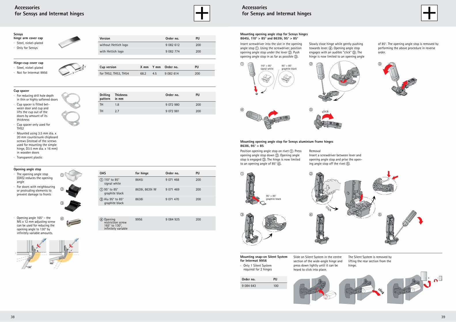
4140
�
�
�
��
click
110° > 85° 95° > 85°signalweiss graphitschwarz
click
�
�
�
�
�
+ -
click
+ -
click
+ -
click
Y
X
�
�
�
�
130°165°
Sensys hinge arm cover cap· Steel, nickel-plated· Only for Sensys
Intermat hinge arm cover cap· Steel, nickel-plated· For Intermat 9930
Hinge-cup cover cap · Steel, nickel-plated· Not for Intermat 9956
Version Order no. PU
without Hettich logo 9 082 612 200
with Hettich logo 9 082 774 200
OAS for hinge Order no. PU
� 110° to 85° signal white
8645i 9 071 468 200
� 95° to 85° graphite black
8639i, 8639i W 9 071 469 200
� Alu 95° to 85° graphite black
8638i 9 071 470 200
Version Order no. PU
without Hettich logo 9 042 838 200
with Hettich logo 9 042 839 200
Cup version X mm Y mm Order no. PU
for TH52, TH53, TH54, TH56
TS52, TS53, TS54, TS56
68.2 4.5 9 082 614 200
for TB52, TB53, TB54, TB56 61.4 4.5 9 084 924 200
Drilling pattern
Thickness in mm
Order no. PU
TH 1.8 9 072 980 200
TH 2.7 9 072 981 200
TB 1.8 9 072 982 200
TB 2.7 9 072 983 200
TS 1.8 9 072 980 200
TS 2.7 9 072 981 200
Cup spacer· For reducing drill hole depth in thin or highly softened doors· Cup spacer is fitted bet- ween door and cup and lifts the cup out of the doors by amount of its thickness· Cup spacer only used for TH52, TB52, TS52· Mounted using 3.5 mm dia. x 20 mm countersunk chipboard screws (instead of the screws used for mounting the simple hinge, D3.5 mm dia. x 16 mm) in wooden doors· Transparent plastic
Opening angle stop· The opening angle stop (OAS) reduces the opening angle· For doors with neighbouring or protruding elements to prevent damage to fronts
Insert screwdriver into the slot in the opening angle stop �. Using the screwdriver, position opening angle stop under the lever �. Push opening angle stop in as far as possible �.
Slowly close hinge while gently pushing towards lever. �. Opening angle stop engages with an audible "click" �. The hinge is now limited to an opening angle
of 85°. The opening angle stop is removed by performing the above procedure in reverse order.
Position opening angle stop on rivet �. Press opening angle stop down �. Opening angle stop is engaged �. The hinge is now limited to an opening angle of 85° �.
Removal Insert a screwdriver between lever and opening angle stop and prise the open- ing angle stop off the rivet �.
Mounting snap-on Silent System for Intermat 9956· Only 1 Silent System required for 2 hinges
· Opening angle 165° – the M5 x 12 mm adjusting screw can be used for reducing the opening angle to 130° by infinitely variable amounts.
Accessories for Sensys and Intermat hinges
165° to 130°, infinitely variable
9956 9 084 925 200
Mounting opening angle stop for Sensys hinges 8645i, 110° > 85° and 8639i, 95° > 85°
Mounting opening angle stop for Sensys aluminium frame hinges 8638i, 95° > 85
Order no. PU
9 084 643 100
Slide on Silent System in the centre section of the wide-angle hinge and press down lightly until it can be heard to click into place.
The Silent System is removed by lifting the rear section from the hinge.
110° > 85° signal white
95° > 85° graphite black
95° > 85° graphite black
click
11739_Sensys_Katalog_1011.indd 40-41 05.06.12 12:47
� Openinge screw
4140
�
�
�
��
click
110° > 85° 95° > 85°signalweiss graphitschwarz
click
�
�
�
�
�
+ -
click
+ -
click
+ -
clickY
X
�
�
�
�
130°165°
Sensys hinge arm cover cap· Steel, nickel-plated· Only for Sensys
Intermat hinge arm cover cap· Steel, nickel-plated· For Intermat 9930
Hinge-cup cover cap · Steel, nickel-plated· Not for Intermat 9956
Version Order no. PU
without Hettich logo 9 082 612 200
with Hettich logo 9 082 774 200
OAS for hinge Order no. PU
� 110° to 85° signal white
8645i 9 071 468 200
� 95° to 85° graphite black
8639i, 8639i W 9 071 469 200
� Alu 95° to 85° graphite black
8638i 9 071 470 200
Version Order no. PU
without Hettich logo 9 042 838 200
with Hettich logo 9 042 839 200
Cup version X mm Y mm Order no. PU
for TH52, TH53, TH54, TH56
TS52, TS53, TS54, TS56
68.2 4.5 9 082 614 200
for TB52, TB53, TB54, TB56 61.4 4.5 9 084 924 200
Drilling pattern
Thickness in mm
Order no. PU
TH 1.8 9 072 980 200
TH 2.7 9 072 981 200
TB 1.8 9 072 982 200
TB 2.7 9 072 983 200
TS 1.8 9 072 980 200
TS 2.7 9 072 981 200
Cup spacer· For reducing drill hole depth in thin or highly softened doors· Cup spacer is fitted bet- ween door and cup and lifts the cup out of the doors by amount of its thickness· Cup spacer only used for TH52, TB52, TS52· Mounted using 3.5 mm dia. x 20 mm countersunk chipboard screws (instead of the screws used for mounting the simple hinge, D3.5 mm dia. x 16 mm) in wooden doors· Transparent plastic
Opening angle stop· The opening angle stop (OAS) reduces the opening angle· For doors with neighbouring or protruding elements to prevent damage to fronts
Insert screwdriver into the slot in the opening angle stop �. Using the screwdriver, position opening angle stop under the lever �. Push opening angle stop in as far as possible �.
Slowly close hinge while gently pushing towards lever. �. Opening angle stop engages with an audible "click" �. The hinge is now limited to an opening angle
of 85°. The opening angle stop is removed by performing the above procedure in reverse order.
Position opening angle stop on rivet �. Press opening angle stop down �. Opening angle stop is engaged �. The hinge is now limited to an opening angle of 85° �.
Removal Insert a screwdriver between lever and opening angle stop and prise the open- ing angle stop off the rivet �.
Mounting snap-on Silent System for Intermat 9956· Only 1 Silent System required for 2 hinges
· Opening angle 165° – the M5 x 12 mm adjusting screw can be used for reducing the opening angle to 130° by infinitely variable amounts.
Accessories for Sensys and Intermat hinges
165° to 130°, infinitely variable
9956 9 084 925 200
Mounting opening angle stop for Sensys hinges 8645i, 110° > 85° and 8639i, 95° > 85°
Mounting opening angle stop for Sensys aluminium frame hinges 8638i, 95° > 85
Order no. PU
9 084 643 100
Slide on Silent System in the centre section of the wide-angle hinge and press down lightly until it can be heard to click into place.
The Silent System is removed by lifting the rear section from the hinge.
110° > 85° signal white
95° > 85° graphite black
95° > 85° graphite black
click
11739_Sensys_Katalog_1011.indd 40-41 05.06.12 12:47
� Openinge screw
4140
�
�
�
��
click
110° > 85° 95° > 85°signalweiss graphitschwarz
click
�
�
�
�
�
+ -
click
+ -
click
+ -
click
Y
X
�
�
�
�
130°165°
Sensys hinge arm cover cap· Steel, nickel-plated· Only for Sensys
Intermat hinge arm cover cap· Steel, nickel-plated· For Intermat 9930
Hinge-cup cover cap · Steel, nickel-plated· Not for Intermat 9956
Version Order no. PU
without Hettich logo 9 082 612 200
with Hettich logo 9 082 774 200
OAS for hinge Order no. PU
� 110° to 85° signal white
8645i 9 071 468 200
� 95° to 85° graphite black
8639i, 8639i W 9 071 469 200
� Alu 95° to 85° graphite black
8638i 9 071 470 200
Version Order no. PU
without Hettich logo 9 042 838 200
with Hettich logo 9 042 839 200
Cup version X mm Y mm Order no. PU
for TH52, TH53, TH54, TH56
TS52, TS53, TS54, TS56
68.2 4.5 9 082 614 200
for TB52, TB53, TB54, TB56 61.4 4.5 9 084 924 200
Drilling pattern
Thickness in mm
Order no. PU
TH 1.8 9 072 980 200
TH 2.7 9 072 981 200
TB 1.8 9 072 982 200
TB 2.7 9 072 983 200
TS 1.8 9 072 980 200
TS 2.7 9 072 981 200
Cup spacer· For reducing drill hole depth in thin or highly softened doors· Cup spacer is fitted bet- ween door and cup and lifts the cup out of the doors by amount of its thickness· Cup spacer only used for TH52, TB52, TS52· Mounted using 3.5 mm dia. x 20 mm countersunk chipboard screws (instead of the screws used for mounting the simple hinge, D3.5 mm dia. x 16 mm) in wooden doors· Transparent plastic
Opening angle stop· The opening angle stop (OAS) reduces the opening angle· For doors with neighbouring or protruding elements to prevent damage to fronts
Insert screwdriver into the slot in the opening angle stop �. Using the screwdriver, position opening angle stop under the lever �. Push opening angle stop in as far as possible �.
Slowly close hinge while gently pushing towards lever. �. Opening angle stop engages with an audible "click" �. The hinge is now limited to an opening angle
of 85°. The opening angle stop is removed by performing the above procedure in reverse order.
Position opening angle stop on rivet �. Press opening angle stop down �. Opening angle stop is engaged �. The hinge is now limited to an opening angle of 85° �.
Removal Insert a screwdriver between lever and opening angle stop and prise the open- ing angle stop off the rivet �.
Mounting snap-on Silent System for Intermat 9956· Only 1 Silent System required for 2 hinges
· Opening angle 165° – the M5 x 12 mm adjusting screw can be used for reducing the opening angle to 130° by infinitely variable amounts.
Accessories for Sensys and Intermat hinges
165° to 130°, infinitely variable
9956 9 084 925 200
Mounting opening angle stop for Sensys hinges 8645i, 110° > 85° and 8639i, 95° > 85°
Mounting opening angle stop for Sensys aluminium frame hinges 8638i, 95° > 85
Order no. PU
9 084 643 100
Slide on Silent System in the centre section of the wide-angle hinge and press down lightly until it can be heard to click into place.
The Silent System is removed by lifting the rear section from the hinge.
110° > 85° signal white
95° > 85° graphite black
95° > 85° graphite black
click
11739_Sensys_Katalog_1011.indd 40-41 05.06.12 12:47
� Openinge screw
4140
�
�
�
��
click
110° > 85° 95° > 85°signalweiss graphitschwarz
click
�
�
�
�
�
+ -
click
+ -
click
+ -
click
Y
X
�
�
�
�
130°165°
Sensys hinge arm cover cap· Steel, nickel-plated· Only for Sensys
Intermat hinge arm cover cap· Steel, nickel-plated· For Intermat 9930
Hinge-cup cover cap · Steel, nickel-plated· Not for Intermat 9956
Version Order no. PU
without Hettich logo 9 082 612 200
with Hettich logo 9 082 774 200
OAS for hinge Order no. PU
� 110° to 85° signal white
8645i 9 071 468 200
� 95° to 85° graphite black
8639i, 8639i W 9 071 469 200
� Alu 95° to 85° graphite black
8638i 9 071 470 200
Version Order no. PU
without Hettich logo 9 042 838 200
with Hettich logo 9 042 839 200
Cup version X mm Y mm Order no. PU
for TH52, TH53, TH54, TH56
TS52, TS53, TS54, TS56
68.2 4.5 9 082 614 200
for TB52, TB53, TB54, TB56 61.4 4.5 9 084 924 200
Drilling pattern
Thickness in mm
Order no. PU
TH 1.8 9 072 980 200
TH 2.7 9 072 981 200
TB 1.8 9 072 982 200
TB 2.7 9 072 983 200
TS 1.8 9 072 980 200
TS 2.7 9 072 981 200
Cup spacer· For reducing drill hole depth in thin or highly softened doors· Cup spacer is fitted bet- ween door and cup and lifts the cup out of the doors by amount of its thickness· Cup spacer only used for TH52, TB52, TS52· Mounted using 3.5 mm dia. x 20 mm countersunk chipboard screws (instead of the screws used for mounting the simple hinge, D3.5 mm dia. x 16 mm) in wooden doors· Transparent plastic
Opening angle stop· The opening angle stop (OAS) reduces the opening angle· For doors with neighbouring or protruding elements to prevent damage to fronts
Insert screwdriver into the slot in the opening angle stop �. Using the screwdriver, position opening angle stop under the lever �. Push opening angle stop in as far as possible �.
Slowly close hinge while gently pushing towards lever. �. Opening angle stop engages with an audible "click" �. The hinge is now limited to an opening angle
of 85°. The opening angle stop is removed by performing the above procedure in reverse order.
Position opening angle stop on rivet �. Press opening angle stop down �. Opening angle stop is engaged �. The hinge is now limited to an opening angle of 85° �.
Removal Insert a screwdriver between lever and opening angle stop and prise the open- ing angle stop off the rivet �.
Mounting snap-on Silent System for Intermat 9956· Only 1 Silent System required for 2 hinges
· Opening angle 165° – the M5 x 12 mm adjusting screw can be used for reducing the opening angle to 130° by infinitely variable amounts.
Accessories for Sensys and Intermat hinges
165° to 130°, infinitely variable
9956 9 084 925 200
Mounting opening angle stop for Sensys hinges 8645i, 110° > 85° and 8639i, 95° > 85°
Mounting opening angle stop for Sensys aluminium frame hinges 8638i, 95° > 85
Order no. PU
9 084 643 100
Slide on Silent System in the centre section of the wide-angle hinge and press down lightly until it can be heard to click into place.
The Silent System is removed by lifting the rear section from the hinge.
110° > 85° signal white
95° > 85° graphite black
95° > 85° graphite black
click
11739_Sensys_Katalog_1011.indd 40-41 05.06.12 12:47
� Openinge screw

Hettich Australia1 Herbert PlaceSmithfield. NSW. 2164Free Phone: 1800 68 77 89Free Fax: 1800 150 129
www.hettich.com.au
Hettich New Zealand18 Barmac PlaceEast Tamaki, AucklandFree Phone: 0800 438 842Free Fax: 0800 73 78 47e-mail: [email protected]
Technik für Möbel
e-mail: [email protected]
116 017 800
Hettich Australia 1 Herbert Place Smithfield 2164, Sydney
Phone: (02)9616 7700 Free Phone: 1800 HETTICH Fax: (02) 9616 7778 Free Fax: 1800 150 129 [email protected] hettich.com.au Online catalogue - hettich.com.au/ecat
Hettich New Zealand 18 Barmac Place East Tamaki, Auckland
Phone: (64) 9274 4036 Free Phone: 0800 HETTICH Fax: (64) 9274 8177 Free Fax: 0800 737 847 [email protected] hettich.co.nz Online catalogue - hettich.co.nz/ecat