
High power flashlamps in dermatology
68
High Power Flashlamps in ermatology A thesis submitted in partial fulfilment of the requirements for the Degree of Master of Science in Physics by Huaying Zhang Department of Physics and Astronomy University of Canterbury New Zealand 1993
Transcript of High power flashlamps in dermatology

High Power Flashlamps in ermatology
A thesis
submitted in partial fulfilment
of the requirements for
the Degree of Master of Science in Physics
by H uaying Zhang
~
Department of Physics and Astronomy
University of Canterbury New Zealand
1993

o
Abstract
Tattoo removal has long been a vexing problem. Although many methods have been involved, most of them are destructive and frequently cause scarring. However Qswitched ruby lasers have been successfully used to remove blue and black tattoos without the usual risks of textural change or scarring (Reid et aI1983). The major difference between this method and the others is that radiation from this laser induces preferential injury to cells containing tattoo pigment only. A major disadvantage of this method is the very high cost of the equipment, and in additional the red tattoos do not respond to red ruby light. This thesis investigates using a high power density xenon flashlamp for the removal of tattoos. The proposed method is based on the same principle as the Q-switched ruby laser, but has potential to remove various coloured tattoos, and to cost rather less than one tenth of the cost of a Q-switched ruby laser. In this thesis the spectral match between absorption of tattoo dyes and radiation of xenon flashlamp has been analysed. I suggest suitable treatment parameters for removal of tattoo using selective photothermolysis after calculation base on some histological studies. The theory of the xenon flashlamp system was analysed in order to design a flashlamp system, and some experimental trials on different pulse durations and brightness were carried out. I report on preliminary clinical trials on a volunteer's tattoos, using different pulse length and energy densities produced by various xenon flashlamps. The overall findings given by our preliminary experiments confirm that a xenon flashlamp with an appropriate energy density and pulse duration C1Ul selectively induce responses in a tattooed area by the mechanism of selective photothermolysis. These clinical trials suggest that an energy density of 8 J cm- 2 is probably the useful treatment threshold for 100 Its pulses.
© May 29, 1993 by Huaying Zhang

Contents
Figures
Tables
1 Introduction
2 History
3
2.1 Motivation for tattoo removal
2.2 Traditional methods
2.3
2.2.1 Surgical excision
2.2.2 Mechanical treatment
2.2.3 Thermal treatment
2.2.4 Chemical treatment of tattoos
Laser removal of tattoos
2.3.1 Argon laser tattoo removal
2.3.2 Tattoo removal with the carbon dioxide laser
2.3.3 Q-switched ruby laser removal of tattoos
The structure of skin and tattoos
3.1 Normal skin structure
3.1) Epidermis
3.1.2 Dermis
3.1.3 Hypodermis
3.2 Dermal cells
3.3 Blood supply
3.4 The professional tattoos
3~5 Amateur tattoos
3.6 Tattoo pigment distribution
4 Mechanisms
4.1 Selectivephotothermolysis concept
111
IV
1
8
8
9
9
9
9
10
10
10
11
11
13
13
13
14
15
15
15
16
18
18
22
22
4.2 Postulated mechanism for removal of tattoos by Q-switched ruby laser 23
4.3 Multiple treatments explanation 24
4.4 Calculations
4.4.1 Thermal relaxation time
4.4.2 Energy intensity
5 Spectrum matching
5.1 Radiation of xenon flashlamp
5.2 Exposure limits to UV
5.3 Spectrum match between tattoo dyes and flashlamp radiation
6 Theory of the xenon flashlamp
6.1 Characteristics of the xenon flash lamp
6.2 Relationship of voltage and current for flashlamp
6.3 Discharge character
6.3.1 Peak current
6.4 Trigger circuit
6.4.1 Why is a trigger circuit is needed?
6.4.2 Over-voltage
6.4.3 External trigger
6.4.4 Series trigger
6.4.5 Simmer trigger
6.5 Conversion efficiency
6.6 . Flashlamp lifetime
7 Clinical trials
7.1 Xenon flashlamp system or Treatment system
7.1.1 Original unit
7.1.2 Modified unit
25
25
26
29
29 31
32
36
36
38
40 43
43
43
44 44
44 45
45
45
47 47
47
50
7.2 Experiments of Pre-clinical trials 51
7.3 Clinical trials 53
7.3.1 Treatment with low energy density and short pulse length 53
7.3.2 Clinical trial with long pulse and high energy density 55
8 Conclusion 57
Acknowledgements 59
References 60

Figures
1.1 An professional tattoo before treatment 3
1.2 An professional tattoo completely removed without apparent scarring 3
3.1 Structure of skin 14
3.2 Tattooing machine 16
3.3 View of tattoo pigment cluster (400 x) 19
3.4 Diffuse tattoo pigments in skin (63 x ) 20
3.5 Tattoo pigments in the skin (63 x) 21
3.6 Distribution of tattoo pigment clusters (63 x) 21
5.1 Xenon flashlamp output spectrum 30
5.2 Three regions of the ultraviolet spectrum 31
5.3 Ordinary glass transmission curves. 33
5.4 UV filter transmission curves 34
5.5 Tattoo dyes relative absorption intensity 34
5.6 Tattoo dyes relative absorption intensity 35
6.1 Basic discharge circuit 38
6.2 Discharge current curves 41
6.3 Discharge current curves 41
7.1 Main discharge circuit of the model 457 A 48
7.2 Radiation pulse shape 49
7.3 Modified discharge circuit 50
7.4 Radiation pulse shape 51
7.5 Bleaching of red paper 52
7.6 Bleaching of the black colour of the typescript. 53
7.7 Bleaching of the black colour of the typescript 54
... 111

Tables
3.1 Distribution of pigment cluster in size in average 19
4.1 Tissue parameters 26 4.2 Thermal relaxation time 27 4.3 Required energy intensity 28
5.1 Spectrum distribution at various current densities 30
7.1 The parameters of the flashlamps 48
IV

CHAPTER 1
Introduction
Tattooing has been practised for at least two thousand years. Artists and scientists
have been improving equipment and dyes gradually. Much effort has been exerted
in attempting to make tattoos brighter, more colourful and stable. Today, excel
lent tattooing equipment and nearly one hundred colours of commercial tattoo dyes
(SpaUlding & Rogers catalogue 1988, 1989-1990, 1991-1992) are used in making tat
toos. On the other hand, tattoo removal is as old as tattooing itself. Scientists and
doctors have been searching for a successful means of removing or concealing tattoos,
using traditional methods such as rubbing with salt, intradermal injection of chemical
irritants, retattooing with flesh coloured pigment or using modern techniques such as
irradiation by laser light.
Many individuals with tattoos want to have them removed without scarnng.
Reasons for tattoo removal include inability to obtain sophisticated employment, a
desire for dissociation from previous imprisonment, 'or to improve social state and
the distaste of family and friends. Sometimes there is a need to remove medical
complications caused by the tattoo.
The problem of satisfactory tattoo removal with acceptable cosmetic results re
mains one of the unsolved areas in plastic surgery. Although many techniques have
been used, no single modality has emerged as the dominant one and thus many meth
ods have evolved. Most of the methods that have been employed over the years cause
significant discomfort at the time of the procedure, produce an open wound that will
require some period of time for healing and will typically replace the original tattoo
with a permanent scar. In some cases, depending upon the anatomic location 'and
individual wound healing characteristics, the resulting scar may be hypertrophic or
even keloidal in nature, leaving the person more disfigured than with the original
tattoo. However, many people prefer a scar to a tattoo.
For years, much work has been done in an attempt to find an effective form of
tattoo removal that did not have the negative consequences of traditional methods.
1

2 Introduction
Various laser techniques for the tattoo removal have been under development since
the mid 1960s. Laser tattoo removal was initially reported by Goldman et al (1963,
1965, 1967) who performed experimental treatment of many lesions, including tattoos,
with different lasers. non-Q-switched andQ-switched ruby, carbon dioxide and argon
lasers, and lasers combined with chemicals have all been studied for the removal of
tattoo. However, except for the Q-switched ruby laser, they still can not overcome
the main disadvantage of producing the scarring which the traditional methods also
cause. Q-switched ruby laser tattoo removal has a different mechanism from that of
other lasers.
One laser therapy mechanism is thermocoagulation. Localised burning of tat
tooed and non-tattooed skin is induced by using a focussed carbon dioxide or argon
continuous output laser. Although the argon laser acts initially by selective absorp
tion, the actual effect of both lasers is to dermabrade the skin layer by layer with
the tattoo pigment being removed. However, an open wound is created and post
treatment care is necessary. Complications of this type of laser treatment include
hypertrophic scarring and residual tattoo pigmentation in most cases.
In the early . 1980's, clinical research performed in Scotland indicated that the
Q-switched ruby laser could be used successfully to remove blue and black tattoos,
particularly amateur tattoos, without the usual risks of textural change or scarring
(Reid et a11983). A later article, 'Q-switched ruby laser treatment of tattoos; 9-year
experience' further reported that both amateur and professional tattoos responded
favourably to treatment, with a few professional tattoos being completely removed
(Reid et a11990). This laser produces a pulse of 4 J with a length of 30 ns to 40ns.
In recent years, Q-switched ruby lasers have been used in clinical treatment in several
places around the world. The nearest clinical laser to New Zealand was in Sydney.
Dr. Bill White worked for Dr. A Scheibner in Sydney, using a Q-switched ruby laser
to remove tattoos for 3 years. Many successful cases were achieved, Figures 1.1 and
1.2 show pictures before and after treatment which were provided by Dr. White.
One advantage of the Q-switched ruby laser is that an open wound is not cre
ated and the skin usually can return to normal texture and normal colour without
scarring. This is the major difference from the destructive therapies. However, some
disadvantages cannot be overcome as they are inherent in the characteristics of this
type of laser. The major disadvantage is the high cost of the equipment. Slow, tedious
treatment is a second disadvantage. A third disadvantage is that this laser cannot be
used for the removal of red tattoos, becau.se the ruby laser emits light of wavelength
694.3nm. The details will be described in Chapter 2.
The mechanisms by which the Q-switched ruby laser is able to provide such
beneficial results are unclear and are being explored. There is no general consensus
at this time and many different explanations have been proposed.

3
Figure 1.1 ,\11 pro fess ion a l Llt too lw for' t reat me nt
Figure 1.2 An profession al tattoo rnm ph~ tcly ["('ITloved withollt. apparpnt scarring

4 Introduction
One theory, which has been advanced by most authors, is that this therapy
mainly works by a mechanism that is often called selective photothermolysis. Incident
radiation is selectively absorbed by the target in the skin. The resultant temperature
rise causes injury to the target. Previous studies in this Department (Pickering 1990,
Halewyn 1987) have analysed the treatment of vascular lesions, where yellow light
absorbed by haemoglobin is used to cook the endothelial wall of the enlarged blood
vessels. It is less clear that similar processes are involved when using a Q-switched
ruby laser to treat tattoos.
There is agreement that the first step of the process is the selective absorption of
ruby laser energy by carbon black and the various metallic dyes used in the creation of
tattoos. However Reid et al (1983, 1990) propose that the best response results from
a combination of at least two mechanisms. The first mechanism is that immediately
the dark tattoo pigments absorb the laser energy, there is a production of steam and
chemical alteration of the the ink into colourless compounds (which they suggested
could be carbon dioxide or carbon monoxide). The second mechanism is that a rapid
increase in temperature causes disruption of the collagen-enclosed pigment particles
by vapourisation of the surrounding tissue water. The usual physiological defence
mechanisms are subsequently invoked to dispose of the debris.
Taylor et al (1990) report the response to treatment with the Q-switched ruby
laser of 36 amateur and 22 professional tattoos. They gave a few explanations of
possible mechanisms responsible for the removal of tattoos, including systemic elimi
nation through the lymphatic system, and external elimination via the scale-crust that
is shed. They also put forward the hypothesis that the decrease in tattoo particles
size and alteration of pigment granule structure using a 'super pulse' are sufficient to
alter the optical properties of the tattoo pigment to make it less apparent. Another
suggestion they made is the same as that given by Reid et ai, that is, the extreme
temperatures that occur transiently at the granules of pigment may be sufficient for
pyrolytic chemical alterations of the pigments.
Scheibner et al (1990) propose that the favourable results obtained in treating
tattoos are the result of mechanical forces or photoacoustic waves, which are generated
in tissue by the high energy pulses from the ruby laser. The effect of the photoacoustic
waves is to rupture the pigment granules by cavitation and fragmentation of the
various metals from which they are made. Once shattered, the pigments are slowly
removed by the inflammatory reaction.
We believe that the selective photothermolysis mechanism plays a major role for
Q-switched ruby laser tattoo removal. But, we propose that it is not necessary to
rupture individual tattoo pigment particles, because very few single tattoo pigment
granules were observed in tattoo specimens in our histological study, rather tattoo
.particles occurred in small and big clusters (see Figure 3.3). The tattoo pigment

5
granules, carbon based or various metals, are sealed by collagen capsules and form
diverse clusters, which are in turn are in tattoo pigment containers (predominantly
in fibroblasts). Breaking up the tattoo pigment clusters or containers is sufficient to
scatter the particles. Then the tattoo fades gradually as the physiological defence
system removes the fragments.
In Chapter 2, we will describe the various traditional and modern methods for
removal of tattoos and their associated advantages and disadvantages.
In Chapter 3, we will describe the structures of normal and tattooed skin. As
well, we will outline the tattooing process and discuss the tattoo dyes used for making
tattoos. We also analyse three specimens of tattooed skin and present the distributions
of the tattoo pigments in depth and size.
In Chapter 4, we will describe the selective photothermolysis concept and analyze
the necessary conditions for applying this principle. As well, we will discuss the
postulated mechanisms of how the Q-switched ruby laser treats tattoos and give an
explanation as to why multiple treatments are necessary. We also do a calculation
to determine the theoretical values for illumination time and the energy intensity
required to break up tattoopigmeIit clusters.
In Chapter 5, we will present the output spectrum distribution from a xenon
Hashlamp and absorption spectrum of several tattoo dyes measured in our experi
ment, and discuss the spectrum match between xenon Hashlamp radiation and tattoo
dyes absorption. We outline exposure limits to ultra-violet on the skin because the
radiation of the xenon Hashlamp contains UV. In order to satisfy the standard for
exposure to ultraviolet when using a xenon Hashlamp for removal of tattoos, the
transmission spectra of the three kinds of UV glass filter are measured and discussed.
The Q-switched ruby laser has a pulse durati6n of 30 to 40 ns (Taylor et at
1990). This thesis argues that such a short pulse duration may not be necessary for
the removal of tattoos. The energy density and the pulse duration required depend
upon the size of the tattoo pigment clusters or containers rather than that of the
particles. The pulse duration required for clusters will be calculated in Chapter 4,
but initial calculations (Pickering et al1989a) suggested to my supervisor that around
10 p,s would be sufficient to kill the fibroblasts and other tattoo pigment containers.
Therefore, he proposed a new method, using xenon Hashlamps to remove tattoos.
Xenon Hashlamps can produce a continuous spectrum output and a high energy
intensity pulse of short duration. The output spectrum from xenon Hashlamps c~vers the range of ultraviolet, visible and infrared. The visible spectrum region covers
the strong absorption bands of various tattoo pigments, as described in Chapter 5.
Xenon f1ashlamps are the brightest non-laser source. They may be an ideal source
for tattoo removal by selective photo thermolysis. Their most important advantage is
that a xenon Hashlamp system is less than one tenth the cost of Q-switched ruby laser

6 Introduction
equipment.
A xenon flashlamp and electrical power supply were ordered from Xenon Corp.
in USA. This system did not meet the specification and could not provide the pulses
that we required. The pulses produced by this system were of 20 IlS duration and the
maximum energy density was 2.5 J cm-2• This does not meet our requirement for pulse
duration of 10 JtS and energy density of 10 J cm-2• However, the Xenon Corp. system
could not give a higher energy density output at the same pulse duration because the
damage threshold of flashlamp is restricted by the pulse duration. I redesigned the
discharge circuit on the original system, in order to obtain higher energy density. The
modified discharge circuit provides pulses with 8 J cm-2 at 550lls or 5.5 J cm-2 at
450 IlS.
Preliminary clinical trials have been done on a volunteer's tattoos with different
pulses which were produced by two xenon flashlamps. Details of the equipment and
clinical experimental analysis will be described in Chapter 6. The treatment area had
black, red and normal skin, the tattoos are 35 years old, are professional and had been
recolored (retattooed). After radiation, the immediate and medium-term responses
were similar to that produced by Q-switched ruby lasers. The experimental results
also showed the response in tattooed area was much greater than in the normal skin,
However, the tattoo colours were not noticeably changed after one treatment, and
skin damage was a little greater than that induced by Q-switched ruby lasers. One
month after treatment, the irradiated area had returned to normal. However the pulse
duration of 550 IlS is much longer than the theoretical value, which we calculate in
Chapter 4.
The overall findings given by our preliminary experiments confirm that a xenon
flashlamp with an appropriate energy density and pulse duration can selectively induce
responses in a tattooed area by the mechanism of selective photothermolysis. The
experimental results also suggest that the pulse duration of the xenon flashlamp should
be improved to be close to the thermal relaxation time of the tattoo pigment clusters.
A new xenon flashlamp with 2280 torr fill pressure and 0.3 em thickness wall is being
designed and manufactured for further trials. This flashlamp should provide pulses of
80 IlS duration and maximum energy density of 10 J cm-2•
In Chapter 6, we will describe the electrical characteristics of the xenon flashlamp
and analyse its discharge circuit behaviour. We also discuss several trigger circuits
including over-voltage, external, series and simmer trigger, and the factors which affect
flashlamp lifetime and efficiency.
In Chapter 7, we will describe the equipment used in our clinical trials and
characteristics of the output from the xenon flashlamps for both the original and the
modified system and also report experimental phenomena of pre-clinical trials. We
found that the xenon flashlamp may have a potential application of bleaching. Vife

7
will describe and analyse the clinical trials which took place on three volunteers with
both systems.
In Chapter 8, we will summarise the results of this thesis. First, a new method of
a high power xenon flashlamp removal of tattoo is proposed for the first time. Second,
we postulate the selective photothermolysis plays a major role for Q-switched ruby
laser tattoo removal, and three necessary factors are presented for the application of
selective photothermolysis technique. Third, there is a good spectral match between
absorption of the tattoo dyes and radiation of the xenon flashlamp. Forth, we propose
new treatment parameters as a result of our histological studies. Fifth, our theoretical
calculation and clinical trials suggest that the pulses of the order of 100 p..s and energy
density of 8 J cm -2 are probably near the treatment threshold for removal of tattoos.

CHAPTER 2
History
In this chapter, we will describes various methods which have been used for removal
of tattoos. As well, we will analyze how they work and their disadvantages. First,
we discuss the traditional methods of tattoo removal which include surgical, mechani
cal, chemical and thermal treatments. And then we will talk about modern methods.
Laser treatment methods have been under development since the mid 1960s (Goldman
et al1963, Goldman et al1965, Goldman et al1967). non-Q-switched and Q-switched
ruby, carbon dioxide, argon and copper vapour lasers, and lasers combined with chem
icals have been studied for the removal of tattoo. However, to date carbon dioxide,
argon, copper vapour and Q-switched ruby lasers have been used clinically for tattoo
removal. Carbon dioxide, argon and copper vapour lasers involve some element of
destruction of the superficial dermis and an open wound. This destruction produces
a direct physical ablation. The Q-switched ruby laser works in a different way from
carbon dioxide, argon and copper vapour lasers. This laser gives the best results of
any system, usually achieving removal of tattoos with no scarring.
2.1 Motivation for tattoo removal
The reasons for requesting removal of tattoos are various, such as, numerous medical
complications, religious reasons, indicating a dissociation from previous imprisonment
or compromised social state, inability to obtain gainful employment or to improve
cosmetic appearance.
Numerous medical complications (Abel et al1972) are well known to result from
tattooing. These range from septic problems to hypersensitivity reactions. Certain
cutaneous diseases, such as herpes, psoriasis, lichen planus, and discoid lupus may
localise in tattoo sites. Acquired hypersensitivity to tattoo pigment is well known,
especially to tattoo dyes containing mercury (red), chromium (green), cobalt (blue),
and cadmium (yellow) (Apfelberg et al1980, Lehmann and Pierchalla 1988).
8

2.2. 'Traditional methods 9
2.2 Traditional methods
2.2.1 Surgical excision
Cold knife surgical excision is a common method for the removal of a small or long,
narrow tattoo (Lindsay 1989). When removing such a tattoo, the surgeon can plan an
excision geometry that forms a closable shape and includes normal and tattooed skin.
On the other hand, the surgeon may choose an excision geometry may be chosen
that cuts as closely around the tattoo as possible. This frequently lea~es quite an
irregularly shaped excision defect, but it wastes a minimum of normal skin. Larger
tattoos may require a series of excisions repeated at 6 monthly intervals. Excision and
split-thickness skin grafting is often employed for large tattoos that have penetrated
the dermis. Surgical excision, however, can result in an obvious scar in both the
tattoo and donor area and can also be expensive. Mr. E. P. Walker, who regularly
uses excision, has provided us with samples for histological study.
2.2.2 Mechanical treatment
Mechanical methods of tattoo removal consist either of re-tattooing or of dermabra-
slOn.
Dermabrasion with the diamond fraize or a wire brush has been used for years for
the removal of tattoos. The tattoo area is anaesthetised and most operators continue
the dermabrasion at the initial sitting until all of the tattoo pigment is removed. This
sometime results in excessive scar formation.
In 1975, Clabaugh described his experience in removing tattoos by dermabrasion
in which he abraded the skin only deep enough to achieve partial pigment removal.
The abraded wound is then painted with 2% aqueous gentian violet and then adaptic
gauze is applied to the denuded surface (Clabaugh 1975). The key aim of both der
mabrasion and the use of the chemical is to prolong the healing process with increased
inflammation, so that a phagocytic response will result in the expulsion of the pig
ment. However, prolonged epithelization, while being helpful with pigment removal,
can increase scarring and disrupt the normal pigmentation by melanin.
2.2 .. 3 Thermal treatment
Thermal methods include both cautery and cryosurgery (Apfelberg and Manchester
1987). Thermal injury, such as that resulting from fire, hot coals, or even cigarettes,
has been used for centuries to obliterate tattoos. Electro-desiccation and electro
cautery with a low power setting, causing superficial damage to the skin, have been
used for tattoo removal but yield scarring for a large percentage of patients. Liquid
nitrogen has also been used to remove tattoos. However, atrophic and depressed areas

10 History
of skin ,often result.
2.2.4 Chemical treatment of tattoos
Caustic chemicals have been used for tattoo removal since as early as 543 AD. The
Greek physician Aetius described a mixture of one part of pepper, two parts of rue
and two parts of orpiment, with unspecified quantities of nitre and turpentine resin.
This was applied to the tattooed area (Scutt 1972). Once all the tattoo pigment was
removed, a fresh layer of the unction was applied with a feather. After twenty days,
there was a large ulcer without any of original marks remaining. However, scarring
was inevitable.
The various effective methods rely on the use of chemical irritants (Scutt 1972,
Hudson and Lechtape-Gruter 1990), such as pricking into the tattooed area a solution
of tannic acid and ending up with rubbing silver nitrate over the top, using pure
potassium permanganate powder inserted into the dermis through multiple superficial
incision, or using trichloroacetic acid, or phenol with and without gentian violet.
However, the complications are difficult to predict. Hyper-pigmentation and ugly
scars occur frequently.
2.3 Laser removal of tattoos
2.3.1 Argon laser tattoo removal
The argon laser has been used in the treatment of decorative tattoos (Apfelberg
and Maser 1979). This laser produces light principally of wavelengths 488nm and
5l4nm. Initially there is selective absorption by tattoo pigment granules in the upper
dermis. Because this laser operates at low power and long exposure, after some
carbonization of the epidermis has occurred, there is non-selective absorption. This
results in some immediate ejection of pigment through the skin. It is evident that
an open wound is created. The resulting charred tissue was left untouched and the
wound was dressed with ilotycin ointment and left open to the air. Patients are
advised to cleanse the wound with hydrogen peroxide and to use the ilotycin dressing
once daily until separation of all eschar. General or local anaesthetic is required before
treatment. Limitations of argon laser treatment of tattoos include the following, 100 /
per cent change in skin texture, 20 per cent incidence of hypertrophic scarring, and
75 per cent incidence of 'ghost' or residual pigmentation (Apfelberg et al1980). Mr.
E. P. 'Valker has used a copper vapour laser in the same way, with similar results.
The 'chemo-Iaser' technique embodying the use of chemical agents and the laser
treatment was developed in 1981 1982. This method has shortened the number of
visits for laser treatment of large tattoos. This method was reported as follows. After

2.3. Laser removal of tattoos 11
argon laser dermabrasion, the skin surface is cleansed with isopropyl alchhol. Cotton
swabs are used with 100% acetone to cleanse the area of tattoo dye. An application of
40 to 50% urea in petrolatum base is effectuated to the entire area for occlusion. The
dressing is left for one week. The area is then dressed with same urea mixture covered
for another week. All patients observe dye on the cotton gauze. Some patients report
soreness. Dismukes (1986) concludes that the effectiveness of argon laser removal of
tattoo can be enhanced with use of agents, and that the number of visits is reduced
to two or three sessions compared with five to eight visits required previously.
2.3.2 Tattoo removal with the carbon dioxide laser
Tattoo removal with the carbon dioxide laser has been reported by many authors
(Brady et al1979, Reid and Muller 1980, Apfelberg et al1985). The carbon dioxide
laser produces continuous light in the infrared spectrum at 10,600nm. The absorption
coefficient of carbon dioxide laser in tissue is very high- the value generally used
is 200 cm-1 (Carruth and Mckenzie 1986). In other words, light from a carbon
dioxide laser will be 90% absorbed. within a distance of only 100,um. This thickness
of tissue is only a few cell widths, which will very quickly be heated to 100°C.
Thus, the carbon dioxide laser can be used to shave cell layers in a very selective
manner. The initial treatment consists of applying a 'brushwork' at approximately
10 watts in order to remove the superficial layers of the epidermis. This layer is then
mechanically cleansed with a saline peroxide solution, and a more specific application
to the underlying upper dermis with its enclosed tattoo pigment is then started under
microscopic control or magnification. As each layer of skin is progressively irradiated,
that layer is then cleansed, and only residual pigmentation particles are exposed. The
carbon dioxide laser is used to dermabrade the skin layer by layer effectively through
the process of thermocoagulation and vaporisation of specific lesions. Therefore, one
can produce a very selective dermabrasion of skin until the lowest pigmentation has
been vaporised. An open wound is created. Postoperative care is usually identical
to that after argon laser treatment. Complications of carbon dioxide laser treatment
include hypertrophic scarring and residual tattoo pigmentation in many cases. Some
clinicians used chemical agents after carbon dioxide laser dermabrasion in the same
way as described for argon lasers (C Vinciullo 1991, private communication).
2.3.3 Q-switched ruby laser removal of tattoos
Q-switched ruby lasers have been used for removal of tattoo in clinical treatment for
many years. The clinical version of this laser produces a 'super-pulse' of 4J with
a wavelength of 694.3nm. This corresponds to very high peak powers because the
pulse duration of this laser is in the range of 30 to 40 ns. It has been reported that
12 History
the power densities of 120 to 280 MW cm-2 are most suitable for tattoo removal. A
number of repeat treatments is necessary, with more repeats for completely removing
professional tattoos than for amateur tattoos.
The advantages of this technique for removal of tattoos are dramatic. First, the
skin returns to normal texture and normal colour without scarring. Second, there is
little need for postoperative care, because an open wound is not created. However,
often little hypo-pigmentation or hyper-pigmentation occurs.
The disadvantages are the cost of the equipment (about $NZ 300,000), and the
need for repeat treatments. The equipment is very expensive, in part, because ruby
(that is, C;+ doped aluminium oxide) has a three energy level system, and so has a
lower efficiency than other lasers with four energy level systems, typically an efficiency
. of 0.5% in non-Q-switched operation. In the Q-switched operation, the efficiency is
about 0.1 % to 0.2%. Its output is also highly sensitive to the operating temperature,
which generally limits its repetition rate. In order to overcome this, a complicated
cooling system is needed. In addition, five to six piece articulated arms are needed to
deliver the light to the treatment area.
Another important disadvantage is that only small treatment areas are possible.
Ruby material is a specially grown single crystal material. It is expensive, particularly
in large sizes, and it is difficult to obtain uniform crystal for a large size ruby laser.
However, uniform light distribution is necessary for the treatment. The limits on
ruby rod size result in a small treatment area and at present most instruments have
5mm diameter treatment area. This results in long treatment sessions and bring
inconvenience and high cost for patients.

CHAPTER 3
The structure of skin and tattoos
An understanding of skin structure is necessary to enable discussion about the in
teraction of light radiation with tattooed skin. We shall outline in this chapter the
structure of normal skin-epidermis, dermis, hypodermis, dermal cells and blood ves
sels. We present analyses of tattooed skin and describe the tattooing process and
tattoo dyes used for making both professional and amateur tattoos. As well, we will
analyse tattoo pigment cluster distributions in depth and size in the tattooed skin.
3.1 Normal skin structure
The skin is the largest organ in the body, constituting approximately one-eighth of
the weight of a normal individual. Its attachment to the body varies. The epidermis,
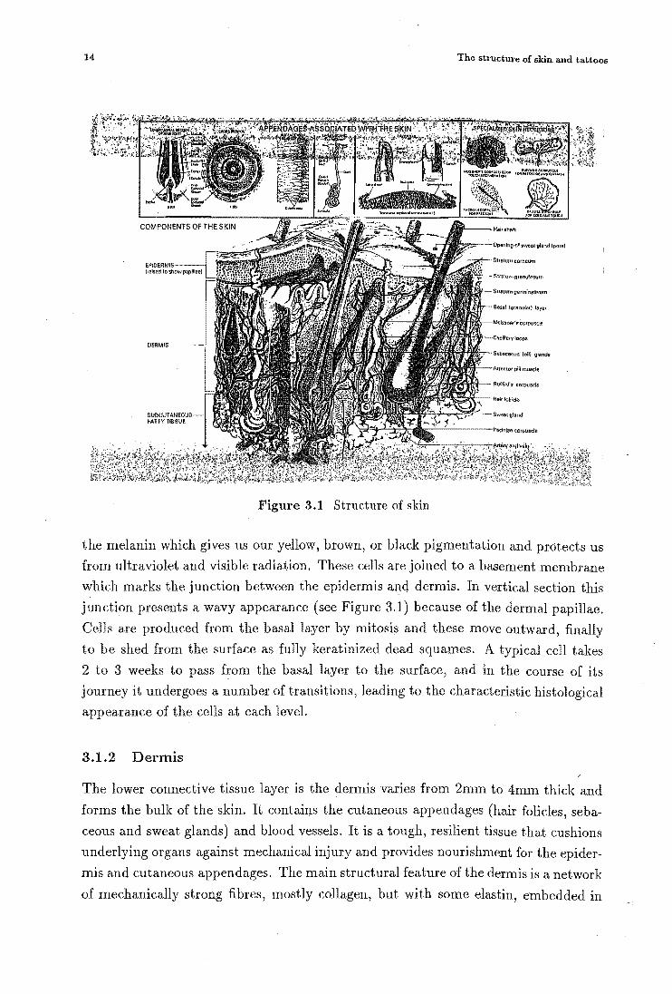
dermis, and adipose make up the skin's three distinct layers. Figure 3.1 is a diagram
showing the structure of normal skin.
3.1.1 Epidermis
The epidermis is the outermost layer of the skin. Five sub-layers of cells 1 may be
recognised histologically. The epidermis is cellular and avascular and is 60 pm to
100 pm thick in most regions, but tending to be thicker on the back and much thicker
in callussed areas.
The epidermis is continually producing new cells being shed, from the time
the embryo has an epidermis until the individual is dead. The growth of epider
mal appendages such as nails and hair is also essentially continuous throughout life.
The very lowest sub-layer of the epidermi~, the basal layer, consists of two types of
cells, melanocytes and keratinocytes. The melanocytes produce small egg shaped
sacks which are called melanosomes, and contain the chromophore, melanin. These
melanosomes are distributed by the melanocytes throughout the keratinocytes. It is
Istratum basal; stratum germinativum; stratum granulosum; stratum lllcidum; stratum corneum.
13
14 The structure of skin and tattoos
Figure 3.1 Structure of skin
the melanin which gives us our yellow, brown, or black pigmentation and protects us
from ultraviolet and visible radiation. These cells are joined to a basement membrane
which marks the junction between the epidermis and dermis. In vertical section this
junction presents a wavy appearance (see Figure 3.1) because of the dermal papillae.
Cells are produced from the basal layer by mitosis and these move outward, finally
to be shed from the surface as fully keratinized dead squames. A typical cell takes
2 to 3 weeks to pass from the basal layer to the surface, and in the course of its
journey it undergoes a number of transitions, leading to the characteristic histological
appearance of the cells at each level.
3.1.2 Dermis
The lower connective tissue layer is the dermis varies from 2mm to 4mm thick and
forms the bulk of the skin. It contains the cutaneous appendages (hair folides, seba
ceous and sweat glands) and blood vessels. It is a tough, resilient tissue that cushions
underlying organs against mechanical injury and provides nourishment for the epider
mis and cutaneous appendages. The main structural feature of the dermis is a network
of mechanically strong fibres, mostly collagen, but with some elastin, embedded in

3.2. Dermal cells 15
a matrix of amorphous ground substance. The fibres (collagen, elastin) are protein
and the ground substance is polysaccharide. In contrast to the epidermis which is
almost entirely cellular, the dermis contains few cells. Those present are mast cells,
macrophages, lymphocytes and melanocytes.
3.1.3 Hypodermis
Beneath the dermis is third layer of the skin. It is a layer of loose connective tissue
called the subcutaneous fatty tissue or hypodermis. Over most the body it forms a
layer of adipose tissue, which provides thermal insulation and mechanical protection
while the fat represents an energy reserve.
3.2 Dermal cells
The dermis, in comparison with the epidermis, is poor in cells, being composed mainly
of connective tissue. The most abundant cell type is the fibroblast which produces
collagen, but the status of these cells in relation to the production of elastin is less
clear and while some authorities maintain that fibroblasts produce all the materials of
the extracellular matrix, others hold that spatial cells produce the glycosaminoglycans
(Wood and Bladon 1985).
Mast cells are common in connective tissue, including the dermis, along with
macrophages. Macrophages, also called wandering histiocytes or phagocytic cells,
originate from blood stem cells. In some connective tissue they are almost as abun
dant as fibroblasts from which they may be distinguished by having an indented, bean
shaped nucleus. Injection of a dye, such as colloidal trypan blue into the dermis, shows
an essential difference between fibroblasts and macrophages: only the macrophages
accumulate particles of the dye. This demonstrates the role of macrophages as scav
engers of foreign particles, fragments of cells or extracellular material. Another dif
ference is found in their distribution. Fibroblasts tend to occur near collagen fibres
whereas macrophages tend to congregate in the region of blood vessels.
3.3 Blood supply
The cutaneous blood supply brings nourishment to the skin but it also has an i~por
tant role in the regulation of body temperature. The skin itself is relatively modest
in its requirements for oxygen but despite this it has a very abundant blood supply.
Arteries paired with veins penetrate the subcutaneous fat and form a plexus just
below the dermis. These vessels are visible on the undersurface of skin on removal.
From this network, vessels rise vertically to supply the mid-dermis. Another plexus
of the smallest arteries and veins are formed just below the papillary layer of the

16 The structure of skin and tattoos
Figure 3.2 Tattooing machine
dermis. These vessels have the highest proportion of muscle in their walls and supply
the glands and hair roots. Shunts provide a means of short-circuiting the capillary
circulation in the dermis to prevent heat loss. Since the epidermis is avascular) it
receives its supply of nourishment from the vessels in the tips of the papillae. The
two vascular layers are connected by vertically oriented arterioles.
3.4 The professional tattoos
Decorative tattoos may be divided for histological purposes into two categories, pro
fessional and amateur. These categories also provide useful clues to appropriate treat
ment.
Professional tattoos are applied using a bunch of needles mounted on a electrical
vibrator (see Figure 3.2), usually 1 or 3, but sometimes up to 14 needles are held by
the needle jigs. The number of needles used depends upon the tattoo pattern. The

3.4. The professional tattoos 17
inside diameter of the needle jig is larger than that of the bunch of needles used so
that the needles be moved back and forth into the jig easily by the driving vibrator.
Usually, the needles retract in the jig.
The tattooing procedure we saw when we visited a tattoo shop in Christchurch
may be divided into three steps. Firstly the artist, John, shaved the hair and cleaned
the skin with methylated spirits where the tattoo was to be done. Then he drew a
tattoo pattern on the skin with indelible pencil. Finally, the tattooing machine was
used. John dipped the tip of the jig in dye which is mixed with water and pigment
powder. The tip of the needles vibrate back and forth along the line of the tattoo
pattern at an small angle to the surface. When the needles go down the needles
penetrate the skin and holes are made. When the needles come back up the tattoo
dye goes in to the skin. Methylated spirits and tissue paper are used in this step,
to absorb the bleeding and remove surplus tattoo dyes. For much of the following
information, I am indebted to Ms Carol Miles. She has a MSc in physics and was a
staff member of this department for many years. She has a background in optics and
dyes.
Carol Miles has had professional tattoos for forty years, and owns professional
tattooing equipment and a range of dyes. She told us that the sensation of tattooing
was like sunburn. She also said that the tattoo was heavily coloured after tattooing.
However, the tattoo's colour became lighter as new skin was formed, because part of
the tattoo pigment peeled off with the crust and part was taken away by the body's
defences. The tattoo pigment fades and spreads out with time. Black tattoos, after
60 to 70 years become light blue. Coloured tattoos, such as yellow, red and blue
disappear 50 years after tattooing. Tattoos fade faster perhaps in 2 to 5 years on
the knuckles and wrists where skin is flexed. Over the years sharp lines of a tattoo
become wider.
Carbon black is used for black and blue tattoos. She also told us of a typical
method for obtaining coloured tattoo dyes. Organic dyes are dissolved in water, ab
sorbed on aluminium hydroxide (AI(OHh), forming an aluminium hydroxide hydrate
(AI( OHh.xH20) which is then heated and ground to powder. The organic dye adheres
to or is trapped inside the Al20 3 granules.
The principal pigments used for present professional tattoos are commercial dyes.
Coloured professional tattoo dyes contain a variety of metals, such as mercury, i~on,
aluminium, cobalt, copper, titanium, chromium, lead, and magnesium. The aim
is both to make tattoo colours vivid and permanent, as reported in many places
(Loewenthal 1960, Silberberg and Leider 1970, Agris 1977, Slater and Durrant 1984).
Spaulding & Rogers MFG., Inc. which has 37 years history in the tattoo supply
business, specify that thier commercial black ink contains 8% carbon, 2% additives
and 1 % other substances.

18 The structure of skin and tattoos
Ms Miles is sure that the majority of modern dyes are organic, but several med
ical references reported that they found various metals in the coloured tattoo skin.
Tattooists have been rather reticent to provide details. We do not know the exact
constituents that used in tattooing and presume that they are organo-metallic com
pounds. It would be worth doing chemical assays on a sample of modern commercial
dyes. We need to know the thermal stability of dyes to fully understand the mecha
nism of selective photothermolysis tattoo removal.
Carol Miles mentioned that the size of tattoo pigment particles is particularly
important. Tattoo dyes must be ground to a uniform size because, while small tattoo
pigment particles will flow away in the body and large ones will be rejected, middle
sized ones of 1 to 5 {tm can stay in the cells. Taylor et al (1990) reported that the
. pigment particles of sizes varying from 2 to 400 nm. We note that the pigment particles
form clusters of typically 1 to 20 {tm in our histological study. The pigment clusters are
in suspension, and it would seem that pigment clusters are surrounded by membranes
(usually fibroblasts) and retained in the skin. Smaller clusters are flushed out through
the lymphatic system, and larger clusters are rejected in the initial scabbing. Such
a behaviour is consistent with the known behaviour of foreign matter in the lung
(C Winterbourn 1989, private communication).
3.5 Amateur tattoos
Amateur tattoos are produced by a nonuniform depth penetration to varying levels
of the epidermis, dermis, or subcutaneous tissue (Taylor et al 1990) by non sterile
or semisterile sharp objects such as needles, pens, and so forth. The pigmentation
consequently varies greatly in location and concentration as well as in particle size.
This variation tends to produce less distinct, blurred lines. Amateur tattoos tend to
be more crude and simplistic than the often elegant and very artistic designs of the
professional tattoo artist. Amateur tattoo pigments are usually obtained from India
ink, pencil lead, lamp black, eyeshadow, shoe polish or carbon particles from burning
charcoal or other substances(Agris 1977, Apfelberg et aI1980).
3.6 Tattoo pigment distribution
Tattoo pigment distribution in the skin has been studied by electron microscope.
Three specimens were provided by Mr. Walker. It is shown microscopically that tattoo
pigment particles accumulate into big or small diverse clumps that are membrane
bound. We can see the shape of the granules on the edge of the cluster in Figure
3.3. However, it is hard to see the single tattoo granules in suspension in tissue in
Figure 3.3, or in other sections. Tattoo pigment granules are sealed by collagen walled

3.6. Tat too pigment distribution 19
Figure 3.3 View of tattoo pigment cluster (400x)
Table 3.1 Distribution of pigment cluster in size in avera.ge
Cluster height (h) percentage
15-30 J1m 20%
5-15J1m 70%
1-5J1m 10%
clusters, mostly in fibrobla ts which surround blood vessels.
In some tattoos, the clus ters of the pigment are scattered throughout the ep ider
mis and de rmis. Specimen 1 shows skin with a pigmented basal epidermal layer. In
the dermis there is patchy accumulation of dark pigment clusters. The siz s of the
clusters vary from 1 to 30 J1m , the depth of distribution varies greatly, from 0.2 to
1.05 mm (see Figure 3.4). There are heavier accumulat.ions of pigment in histiocytes
aggregated around blood vessels.
Specimen 2 shows dark pigment clusters (see Figure 3.5). The clu sters have
aggregated in the upper and mid dermis, the depth of clusters in the skin is from
0.15 to 0.5 mm a nd the size of the cluster::; range from 1 to 20 J1m. Sp ecimen 3 shows
accumulations of dark pigment in his ti ocyte in tIle uppe r and mid de rmis (see Fig me

20 The s tructuxe of skin and tatlo os
Figure 3.4 Diffuse tattoo pigments in skin (63 x )
3.6) . The size of pigment clusters varies from 1 to 20 fim and the depth of the pigment
clll sters from 0.1 to 0.6 mm.
From the above analysis, we find out that t.here are great variations in depth
from 0.1 nun to 1 mm for tattoo pigment. clusters. The size of pigmel1t clusters varies
from lfim to 30fiIll. The size of must of the clusLers is between 5fim and 15fim. Our
measured size distribution of pigmel1t clusters is shown in Table 3.1.

3.6. Tattoo pigment disLribution 21
Figure 3.5 Ta ttoo pigments In the skin (63 x)
Figure 3.6 Dist ribution of ta.ttoo pigment clusters (63x)

CHAPTER 4
Mechanisms
In this chapter we will first describe the selective photo thermolysis concept and an
alyze the necessary conditions for applying this principle. Then we will discuss the
mechanism of the Q-switched ruby laser when used for the treatment of the tattoos.
We postulate that this laser works by selective photothermolysis, and thus propose
that repeat treatments are necessary for this reason. Finally, we will calculate the
thermal relaxation time so that we can determine theoretically an upper limit for the
duration of the pulse of radiation, and a minimum energy intensity necessary to break
up tattoo pigment clusters by selective photothermolysis.
4.1 Selective photothermolysis concept
'Selective photothermolysis' refers to the concept of producing specific, thermally me
diated injury to optical targets in the various tissues, using brief and selectively ab
sorbed radiation. The desired targets may be pigmented skin structures and pigment
containing cells. Tissues between targeted structures, including overlying or immedi
ately neighbouring cells, are spared, reducing widespread destruction and nonspecific
fibrosis. The selective photothermolysis mechanism may be particularly useful in
highly scattering tissues.
The technique of selective photothermolysis relies on selective absorption of a
brief radiation pulse to generate heat in inside the target volume, so that damaging
temperatures rises are confined to the target, thus avoiding injury to surrounding
tissue. This principle of localising the thermal damage to specific targets in the
radiation field has been successfully employed to destroy the abnormally ectatic blood
vessels in port wine stains and skin telangiectases. More recently, attention has been
directed at the cutaneous endogenous chromophore, melanin, especially in the brown
marks common in asian skin or 'age-sports' in caucasian skin.
The effectiveness of selective photothermolysis depends upon the ability to confine
the temperature rise specifically to the target. There are three conditions which
22

4.2. Postulated mechanism for removal of tattoos by Q-switched ruby laser 23
have to be met when this technique is applied. The. first condition is a sufficient
spectral match between the radiation and the targets. That is, the targets must have
a greater optical absorption at some wavelength than their surrounding tissues. This
requirement can be met either by choosing an appropriate spectral region of radiation
or by using a staining or dye-labeling technique.
The second condition is that the time of the energy delivery must be shorter
than that of significant thermal conduction. The light exposure duration dictates
the extent of the local confinement of the heating effect produced. During the light
exposure, radiation energy is converted into heat within each target in the exposure
field. Accompanying this heating the targets begin to transfer the heat to their cooler
surroundings mainly by thermal conduction, but this process takes some time which
depends the exposure duration. In order to obtain rapid heating of the targets and
to generate a irreversible effect on them, the exposure time must be of the order of,
or less than the thermal relaxation time of the targets discussed in detail in section
4.4.1.
The third condition is that a sufficient energy density is necessary to generate the
thermal effects required. These effects include coagulation necrosisl and vaporisation2
of tissues.
4.2 Postulated mechanism for removal of tattoos by Q-switched
ruby laser
Q-switched ruby lasers are able to remove tattoos completely without the usual risks
of textural change or scarring. The reason for that is that output parameters of pulse
duration, energy intensity and wavelength from this laser satisfy the conditions for
the selective photothermolysis technique. The radiation specifically targets tattoo
pigment in the skin, and the other parameters are such that any damage to the
surrounding tissue is repaired.
First, the deep red light from the Q-switched ruby laser, having a wavelength of
694.3 nm, is beyond the main absorption peak for hemoglobin and less absorbed by
melanin in the epidermis than by tattoo pigments. Although there is some reflection
on the skin surface and some scattering in the skin, some of the light penetrates the
translucent epidermis and dermis, and is absorbed by carbon pigments.
Second, Q-switched ruby lasers produce very short pulses of radiation with high
intensity. The pulse duration of 30 to 40 ns is much shorter than the thermal relaxation
time of even the smallest pigment clusters (see Table 4.2). Hence the temperature
1 Normal skin temperature is about 35°C and if soft tissue is heated from this level to above 60°C
the process of coagulation begins.
2When tissue is heated to above 100°C the process of vaporisation occurs

24 Mechanisms
rise of the cluster will be much higher than that of the surrounding tissue, resulting
in little damage to this tissue.
Because of the above factors, most of the radiation from the Q-switched ruby
laser is absorbed by tattoo pigments. Absorption and radiationless de-excitation
convert radiant energy into heat within each tattoo cell in the exposed area. Large
temperature rises are induced in the vicinity of the pigment clusters. The cell fluid
will boil when tissue is heated to above 100°C, since the body cells may be considered
to be mostly water under normal atmospheric pressure. The conversion of water
into steam represents a thousand-fold expansion and leads to an explosive interaction
which breaks up the tattoo pigment containers.
The pigment particles are then released from the containers. This effect pro
motes an accumulation of macrophages 3 in the injured area. Fragments of the con
tainers and tattoo pigment granules are removed through the process of phagocytosis.
Macrophage activity transports the scattered pigment particles away. Tattoos gradu
ally fade. Usually this process takes two to three weeks.
However, the Q-switched ruby laser cannot remove coloured tattoos other than
blue and black because the ruby laser light has a wavelength of 694.3 nm. The ab
sorption spectrum of several dyes are shown in Figures 5.5 and 5.6. There is little
absorption at 694.3nm for orange, gold yellow, yellow, brown and violet tattoo pig
ment, but black, white and green tattoo dyes have a high absorption at 694.3 nm.
4.3 Multiple treatments explanation
A number of repeat treatments are required to remove tattoos completely in most
cases. Re-treatments necessary for amateur tattoos vary between four and six. For
professional tattoos, six or seven, even as many as twelve treatments may be necessary
to obtain optimal results. However, on occasions only one or two treatments has been
needed to remove a tattoo completely C\Vhite 1992a, b) .
We propose that the number of repeat treatments necessary depends on distribu
tion in density and depth of the tattoo pigment clusters. Histological studies detailed
in Chapter 3, show that the distribution of tattoo pigment clusters range in depth
from 0.1 to 1 mm below the skin surface. Blue and black tattoo pigments absorb
100% of incident light on them, so it is probable that little light penetrates beneath
the upper cells of the tattoo. This results in only the upper of tattoo pigment ~ells responding on anyone exposure. The tattoo pigment within the skin can be removed
layer by layer by this selective photothermolysis mechanism. The higher the density
of pigment clusters, the higher number of treatments. Professional tattoos need more
3Macrophages are the white blood cells that surround and carry away foreign particles or dead
cells.

4.4. Calculations 25
treatments than amateur tattoos, because the pigment clusters of professional tattoos
are generally of a higher density.
Calculations
4.4.1 Thermal relaxation time
The duration of the pulse of radiation is a very important treatment parameter for
selective photothermolysis. It determines the illumination time. The illumination
time determines the extent of conduction of delivered energy from the target. To
minimum conduction losses, the illumination time must be less than the thermal
relaxation time (T) of the target (Kuban et al 1992). The thermal relaxation time
of the target is an estimate of the time required for the target to release a certain
fraction of the heat within it. In the case of a target in the skin, this time is normally
defined as: the time it takes for the central temperature to fall to half way between its
peak temperature and the temperature of the surrounding structures (Pickering et al
1989b). We apply this definition to tattoo pigment clusters in the skin to estimate a
maximum optimal illumination time.
To calculate thermal relaxation time we begin with the fundamental law of heat
conduction
where
dQ -+ = -T] A .\11'
dt
• Q is the heat within the structure,
• t is the time,
• T] is the thermal conductivity,
.. A is the area through which the heat is conducted,
• \11' is the temperature gradient.
(4.1)
In the case of tattoo pigment clusters, we make the assumption that the cluster is a
sphere of radius r, and that the normal tissue temperature, 1'0 is 35°C.
Immediately after exposure, the average temperature of the tattoo pigment clus
ters has increased by llT (llT = l' - 1'0)' The excess heat energy within the cluster
is given by
( 4.2)
If we assume that the temperature throughout the cluster is uniform and as simplifi
cation take the temperature gradient at the surface of the cluster as /::;rT approximately

26 Mechanisms
then substituting in equation 4.1, we have
dQ 2!::..T - = -471'1I"r -. dt r
(4.3)
The tissue parameters Cu , p and 71 are presented in Table 4.1. combining equations
(4.3) and (4.2), we obtain d(!::..T) _
!::..T -
Integrating equation 4.4, we have
where (!::..T)o is the initial increase in temperature. Then, letting
(4.4)
(4.5)
(4.6)
According to our definition of then;nal relaxation time, we have for a 50% drop in the
relative peak temperature a· thermal relaxation time( r) of
r = Toln2. (4.7)
The ultimate goal of defining the 'optimal' parameters will be specifically to
destroy only tattoo pigment cells in the cutaneous tissue. If the illumination time is
much longer than the thermal relaxation time of the target then during its heating a
considerable amount of heat will be conducted away and the surrounding structures
can be expected to be heated because the tattoo pigment cells are not thermally
isolated.
The thermal relaxation time depends upon the size of the pigment cluster and
values for varying radius of tattoo pigment clusters are shown in Table 4.2. We found
from histological studies that most tattoo pigment clusters are around 5 to 15 p.m in
diameter and therefore pulse duration .ought to be less than 100 p.s.
Table 4.1 Tissue parameters (Pickering et a11989a)
Parameters Values
Density(p) 103 kg m-3
Heat capacity ( Cv ) 3.5x 10³ J kg-1OC-I
Thermal conductivity( 71) 0.62 W m- I °C-I

4.4. Ca.lcula.tions 27
Table 4.2 Thermal relaxation time
Pigment cluster size (radius) Thermal relaxation time( l' )
1 pm 1 J.LS
2pm 5 J.LS
5pm 30 J.LS
10 pm 130 J.LS
15 pm 300 J.LS
20 pm 500 J.LS
4.4.2 Energy intensity
According to the mechanism of selective photothermolysis removal of tattoos, the
energy intensity must be sufficient to heat tattoo pigment cells to a temperature that
results in tattoo pigment cells breaking up. Therefore the exposure dose is also a
very important treatment parameter. However, it is a complex question to estimate
accurately the exposure dose required on the skin surface. The tattoo pigment cells
are not isolated, they are suspended in the tissue and cannot be exposed directly. It is
also unknow as to whether it is sufficient to denature the protecctive container (70°C)
or necessary to rupture the cells explosively (100°C).
There are loss of incident energy before the light reaches the tattoo pigment
cells due to the optical properties of human skin. Firstly, there is a reflection loss on
the skin surface. At near-normal incidence, a small fraction of incident radiation is
reflected due to the change in refractive index from air (ni = 1.0) to stratum corneum
(nt = 1.55) (Scheuplein 1964). This regular reflectimce of an incident beam from
normal skin is betweeen about 4% and 7% over the entire spectrum from 750 nm to
3000 nm for both white and black skin.
Output light from the xenon flash lamp radiates in all directions. In this case,
reflection is increased. Fresnel's formula predicts about 10% of incident light is re
flected from the skin surface. The reflection results because the surface of the stratum
corneum is not smooth and planar: (1) the regular reflectance from skin is not specu
lar and (2) a beam of incident radiation in all directions, passing through this surface
and into skin, is refracted and therefore is made somewhat more diffuse by this rough
surface. These effects are similar to those which make ground glass translucent, com
pared with the transparency of polished glass.
Secondly, the incident radiation of 90%, not returned by regular reflectance, may
be absorbed or scattered in the skin before reaching tattoo pigment cells. In the epider
mis, melanin is the major absorber of radiation. The absorption of melanin depends
upon the wavelength, having a high absorption peak at less than 275 nm (Anderson

28 Mechanisms
and Parrish 1981). There is also scattering in the skin, resulting from inhomogeneities
in a medium refractive index, corresponding to physical inhomogeneities. For particles
with dimensions on the same order as the wavelength, scattering is much stronger. In
particular, scattering by collagen fibers appears to be of major importance in deter
mining the penetration of optical radiation within the dermis (Anderson and Parrish
in 1980).
These two factors taken together essentially determine the penetration of radi
ation before reaching tattoo pigment cells. A total incident radiation loss of 30% to
50% in these two processes was estimated by considering the treatment of port wine
stains (Pickering et aI1989a).
In our experiment, we found that there is more loss in the epidermis during the
exposure, which will be discussed in chapter 7.
In our calculation, we assume that the tattoo pigment cells are exposed directly
and do not consider various losses on the skin surface and in the skin. We assume the
tattoo pigment cluster to be a disk with thickness h and cross sectional area S. To
heat such a cell to 100° C, the energy required is
( 4.8)
where the energy intensity D=Q /S is
( 4.9)
Table 4.3 Required energy intensity when the tattoo pigment cluster is directly exposed
Pigment cluster thickness (h) Energy intensity
2/Jm 0.07 Jcm- 2
5/Jm 0.17 Jcm-2
10/Jm 0.35 Jcm-2
15/Jill 0.53 Jcm- 2
i 20/Jm 0.70 Jcm-2
.Table 4.3 gives minimum energy intensity which is required to heat tattoo pig
ment clusters to 100°C when exposed directly. If we take into account energy losses on
the skin surface and in the skin, the expo~ure dose used on the skin surface should be
higher than above results suggest. Reid et al reported however that energy intensity
of rang 4 to 8J cm-2 are required for the Q-switched ruby laser treatment.

CHAPTER 5
Spectrum matching
In this chapter we will discuss particularly the spectrum match between the xenon
fiashlamp's radiation and the absorption of the tattoo dyes. First, we will present the
output spectrum from the xenon fiashlamp and the measurements we have made of
the tattoo dyes absorption and analyze the spectrum match in the visible region.
Secondly, we discuss exposure limits to the exposure of the skin to ultraviolet
because the radiation of the xenon fiashlamp contains UV. We have measured the
transmission spectrum of three kinds of UV glass filter and that ordinary window
glass provides sufficient absorption to satisfy the standard for exposure of the skin to
UV radiation. As well, it also has a high transmission rate in the visible region.
5.1 Radiation of xenon flashlamp
Spectral output from a xenon fiashlamp covers a wide range of wavelength. This
extends from ultraviolet to infrared. The spectral output of a xenon fiashlamp de
pends to a great extent on the discharge current density. For instance, at low current
density the spectral output is heavily weighted toward the visible and infrared .. As
current is increased, the output spectrum shifts toward the blue and ultraviolet. This
occurrence is illustrated in Figure 5.1 which shows spectral curves for the Model-457 A
high current intensity, micropulse system. Table 5.1 shows the spectral distribution
at various current densities. Spectral output is also affected by the envelope mate
rial of the fiashlamp. Natural fused silica is often used as a envelope material. Its
transmission spectrum ranges from 175 nm to 5000 nm.
29

30 Spectrum matching
Wavelength Spectrum distribution (%) (nm) 400-1500(A cm-2 ) 2000-5500 (A cm-2 ) 6000-14000(A cm-2)
200-300 5 8 20
300-400 11 16 15
400-500 14 17 14
500-600 13 14 14
600-700 10 10 7 800-900 16 11 8
900-1000 15 {) 7 1000-1100 5 4 3
Table 5.1 Spectrum distribution at various current densities. This table gives the spectrum
distribution of three ranges of current densities (Xenon Corporation, 1992).
9
8
7 I>.
+" 7 'r-< fI:J ~ <I,)
+" 5 . S <I,) :>- 4 .....
+" <Q
~ 3
2
1
, • " ., .. .. : :~ .... · . • • · . • • · . · . · . · . · . · . . : :
:: ~ :'" .,: :: .. : .. ~ ... _/ .. .. " ' .. " ,
• .. '" I'·,
"" " .. .............. '\ •• :It ' .. .""-', .. ,: :., -.. "
'-, '" .. ': · · · . ............ 200 300 400 500 600 700 800 900 1000 1100
wavelength (nm)
Figure 5.1 Xenon flashlamp output spectrum of the Model-457 A high intensity micropulse
system. The dotted line corresponds to a high current density and the solid line corresponds
to a low current density (Xenon Corporation, 1992).

5.2. Exposure limits to UV 31
X-ray Ultraviolet Visible Infrare d
/oOnm 4oo~oonm
uve UVB UVA
100nm 280nm 315nm 400nm
Figure 5.2 The ultraviolet spectrum is divided into three regions, UYA, UYB and UYC.
5.2 Exposure limits to UV
Because the flashlamp output spectrum includes ultraviolet, it is important to under
stand ultraviolet exposure limits to prevent hazard to the treated skin.
Exposure to ultraviolet radiation can produce harmful effects in the skin. These
include the effects of acute and chronic. The former include erythema, oedema and
blistering. Most acute biological effects are initiated by wavelengths less than 315 nm.
The wavelength range 180-315 nm is often referred to as the actinic region. Chronic
effects of exposure to ultraviolet radiation include premature skin aging and skin
cancer. As with acute effects, the most dangerous wavelengths appear to be those
below 315 nm.
We investigated the exposure limits for ultraviolet carefully. There is no New
Zealand standard or legislation prescribing maximum permissible exposures to ultra
violet radiation. However, we obtained a document 'Occupational Standard for Expo
sure to Ultraviolet Radiation' from the National Radiation Laboratory in Christchurch.
This document was approved at the 108th session of the National Health and Medical
Research Council in Canberra in 1989 and was published by the Australian Radiation
Laboratory on behalf of the National Health and Medical Research CounciL
This standard is for both general and occupational exposure to ultraviolet radi
ation incident upon the skin or eye. The exposure limits are considered separately
for the three regions of ultraviolet. The international commission on illuminationhas
divided the wavelengths between 400 nm to 100 nm into three regions. Figure 5.2
shows the three regions UVA (315-400 nm),' UVE (280-315 nm) and uye (280-180 nm).
For the wavelengths of the three regions of DVA, DVB and Dve the exposure limits
are given in the National Health and Medical Research Council (National Health
and Medical Research Council, 1989). For example, for the wavelengths 315nm and

32 Spectrum matching
400nm UVA the total radiant exposure incident upon unprotected skin should not
exceed 1.0 J cm-2 and 100 J cm-2 respectively within an 8 hour period. However,
for the wavelengths 305 nm and 270 nm the total radiant exposure incident upon
unprotected skin should not exceed ~O X 10-3 J cm-2 and 3 X 10⁻³ J cm-2 in a
similar period. The exposure limits for UV are very different for regions of UVA, UVB
and uvc. Generally the exposure limits for the regions of UVB and uvc are much
lower than for UVA.
When the flashlamp operates at high current density, an UV filter is needed
in order to prevent hazard to the treatment area. We measured the transmission
spectrum of three kinds of glass by a UV /Vis spectrometer (Model Lambds 2) in
chemistry. The first was ordinary glass of 1 mm and 5 mm thickness. This glass filters
. out the two regions UVB and UVC while about 94% of the visible spectrum passes
through. The transmission spectrum curves of ordinary glass are shown in Figures
3(a) and 3(b). The second type of UV filter glass was a cesium doped fused silica
jacket supplied by the Xenon Corporation to cover the flashlamp. There is about 30%
penetration in the spectrum range of 220 nm to 280 nm and there are two valleys at
220 nm and 320 nm in the transmission curve shown in Figure 5.4. Thirdly, we used
UV filter glass supplied by AG Thompson. This filter cuts off the entire region of
UVA and UVB and the infrared. However, visible transmittance is lower than with the
other glasses (see Figure 5.4). By comparing the three kinds of glass, we think that
5 mID of ordinary glass as a ultraviolet filter in our application is sufficient.
5.3 Spectrum match between tattoo dyes and fiashlamp ra
diation
We obtained eight colour tattoo dyes manufactured in 1965 by Fazandie Sperrle Inc ..
The colours are violet, green, brown, yellow, gold yellow, orange, white and black.
Their absorption spectra in the visible region were measured by a UV /Vis spectrom
eter (Model lambda 2) in chemistry. The samples were prepared by smearing the dry
tattoo powder on the paper and measurement was carried by reflection. Black and
white tattoo dyes have a uniform absorption over a range of measurement (350 nm -
750nm).
The relative absorption intensity of the remaining six tattoo dyes (violet, green,
brown, yellow ,gold yellow and orange) as a function of wavelength are shown in
Figures 5.5 and 5.6. These curves show the position of their maximum absorption
wavelengths and the range of absorption for each tattoo dye. It is evident that the
absorption spectrum range of the six tattoo dyes covers the entire visible region from
400 nm to 700 nm. It indicates that over much of the visible spectrum there is a
good match between the radiation of the xenon flashlamp and the absorption region

5.3. Spectrum match between tattoo dyes and fiashlamp radiation 33
100.00
80.00
60.00
T 40.00
20.00
0.00
300.0 350.0 400.0 450.0 500.0 550.0 600.0 650.0 700.0
wavelength
(a) 5mm glass thickness
100.00
80.00
60.00
T 40.00
20.00
0.00
300.0 300.0 400.0 500.0 600.0 700.0
wavelength
(b) 1 mm glass thickness
Figure 5.3 Ordinary glass transmission curves.

34
100.00
80.00
60.00
T 40.00
20.00
0.00 200.0 300.0
... .,. .............. .. .' . fi"''''~ .. ~ .. . ' .
,.# ... p' • . . , . . • . • • . . . • .
400.0 500.0 600.0
wavelength (nrn)
. . . . . . • • ..
Spectrum. matching
". 100.0
Figure 5.4 UV filter transmission curves. The dotted line corresponds to a 1 mm Band
pass filter transmission curve .. The solid line corresponds to a 1.5 mm cesium doped fused
silica transmission curve.
1.0000
0.8000
0.6000
A 0.6000
0,2000
0.0000
400.0
..... , .......... ,<I' ........ - .. ~ til. .... .. .... .- .... ., ........ ..... ............. GY "' .... ,,\ .. ,. "
\'" . \ \ \
'. \ . . .... \,
···~··· •••••••••••••••••••••••••• IIt1
450.0 500.0 550.0 600.0
wavelength nrn 650.0 100,0 150.0
nm
Figure 5.5 Tattoo dyes relative absorption intensity. Curves 0, G and GY represent
orange, green and gold yellow tattoo dyes respectively.

5.3. Spectrum match between tattoo dyes and flashlamp radiation 35
1.0000
0.6000
0.6000
A 0.60PO
0.2000
0.0000
400.0 450.0 500.0 550.0 600.0 650.0 700,0 750.0
wavelength nm nm
Figure 5.6 Tattoo dyes relative absorption intensity. Curves V, Y and B represent violet,
yellow and brown tattoo dyes respectively
of tattoo dyes. This, which may be one of important advantage for the removal of
tattoos by xenon fiashlamp, was exp'erimentally verified. A fiashlamp with output of
20 JLS and 2.5 J was used on a volunteer's tattoo. The skin area had black and red
tattooed area and normal skin. The experimental results showed the response in the
black area was greater than that in the red tattoo, which was a little greater than for
normal skin.
We also observed that there is no absorption peak for the six tattoo dyes in
region of 650 nm to 700 nm. This result explains why Q-switched ruby lasers are not
successful in removing most coloured tattoos,

CHAPTER 6
Theory of the xenon flashlamp
It is very important to optimise the design of the flashlamp bore, length and fill
pressure to match its electric circuit, so that the system obtains the highest possible
radiation efficiency. The flashlamp will also have a proper lifetime, and its output
spectrum will satisfy the treatment requirements. Hence it is necessary to study
the characteristics of the flashlamp, itself its output and electrical circuit are of
particular interest for this purpose.
In this chapter, we will mainly discuss characteristics of linear flashlamps. First,
we will describe what a xenon flashlamp is and its idealized electrical characteristics.
Then we will present an analysis of the discharge circuit behaviour of a flashlamp,
such as the relationship of voltage and current for the flashlamp and the peak current
through the flashlamp. As well, we will discuss the importance of the flashlamp
operating at critical damping and how to design an electrical circuit to achieve this.
We also discuss several trigger circuits including over-voltage, external, series and
simmer trigger. We will also analyse the factors which affect flashlamp lifetime and
efficiency.
6.1 Characteristics of the xenon flashlamp
Xenon flashlamps are gas discharge tubes, filled with the inert gas, xenon, designed to
produce both pulsed and continuous radiation. Xenon lamps are similar to all other
arc lamps in that optical radiation is produced by passing an electrical current through
a gas. A continuum spectra is produced when sufficient energy is transferred to the
xenon gas atoms to cause excitation and ionisation. Xenon is used in most flashlamps,
since it is the most efficient of the inert gases at converting electrical energy to optical
energy. For pulsed operation, the current is supplied by a charged capacitor capable of
discharging the appropriate energy in the appropriate time. Depending on the values
of the capacitor and other circuit components, pulse widths from under 1 microsecond
to over 50 milliseconds and energies from millijoules to kilojoules can be obtained for
36

6.1. Characteristics of the xenon flashlamp 37
xenon fiashlamps.
The characteristic of producing energy in pulses of extremely high peak values
and very short duration is a great advantage. A further advantage is that the output
spectrum is broadband. However, specific regions of the spectrum can be emphasized
by controlling the current through and the filling pressure of the fiashlamp. These
make them universally used for lasers, phototypesetting, chemical analyses, medical
purposes etc.
Xenon fiashlamps are available in many sizes and shapes including linear, bulb,
helical and U-shaped and so on. But while there are many shapes of fiashlamps, there
are only two distinct basic types, linear and bulb.
The bulb type fiashlamp is constructed from a small glass bulb. Bulb type flash
lamps differ from linear flashlamps in that the arc is un-confined. The arc is formed
between two electrodes mounted near the centre of the bulb. There are between one
and five trigger probes, depending on the arc length and the space between the elec
trodes. This has the effect of applying a trigger voltage gradient across the probes.
The trigger streamer strikes first from the cathode to the number 1 probe, then the
segment from probe number 1 to number 2 is filled in, and so on until a complete trig
ger streamer is formed from the cathode to the anode. At this point, a low resistance
path is formed, then the main capacitor dumps its stored energy into an arc following
exactly the same path as the trigger streamer. This guide for the arc configuration
results in an extremely stable source. Since the plasma does not contact the bulb wall,
very long lifetimes can be obtained. Standard arc lengths available are 0.15, 0.30 and
0.80 cm. The combination of an un-confined arc and a short arc length results in
very low arc impedance, therefore pulse duration are very short, typically between
0.7 and 15 microseconds. However, the output spectrum is very rich in the blue and
ultraviolet and the maximum efficiency is about 20% for converting electrical energy
to optical energy.
The linear type is of glass or quartz tubing construction with an electrode mounted
at each end. The bore (inner diameter of the lamp) is completely filled with ionised
gas when the lamp is flashed. Linear flashlamps can be made into a variety of shapes
including helical, ring, U; electrically, however, there is no difference between two
lamps that have same bore size, arc length (distance between electrodes), and fill
pressure. Bore sizes from 0.1 to 1.9 cm and arc lengths from 2.5 to 120 cm are
commonly available.
The driving circuit for a linear flashlamp is shown in Figure 6.1. This gives an
useful illustration of how a fiashlamp works. In the main discharge circuit an inductor,
L, is placed in series with the flashlamp and capacitor, C. In the non-ionised state, a
flashlamp has a high impedance; therefore all current from the power supply initially
flows into the capacitor C. As the voltage across the capacitor is increased, a point

38 Theory of the xenon fiashlamp
+ C
Figure 6.1 Basic discharge circuit
of charging voltage (Vo) is reached, called the breakdown voltage, where xenon atoms
are ionised and the impedance of the flashlamp starts to drop. In a short period of
time, enough xenon atoms are ionised so that a low impedance path is formed from
anode to cathode and the current flows from the capacitor through the flashlamp. As
this occurs, more xenon atoms are ionised; the arc impedance continues to drop and
expands outward eventually filling the bore of the flashlamp. Once most of the energy
stored in the capacitor is expended, the current through the flashlamp drops to such
a low level that the gas de-ionised and stops conducting. At this point, the capacitor
starts recharging.
6.2 Relationship of voltage and current for fiashlamp
The main discharge circuit cannot be treated as a traditional RLC circuit, because the
flashlamp does not behave as a linear resistor. Various relationships between voltage
and current for flashlampshas been found. Goncz (1964) found the instantaneous
flashlamp voltage (V) and current (i) to be related by:
(6.1)
1<0, the flashlamp impedance, is totally determined by the flashlamp geometry and
fill pressure. This parameter is calculated using the formula
J{o (6.2)
where
" 1 is arc length in mm,

6.2. Rela.tionship of voltage and current for fiashlamp 39
• d is bore size in mm,
1\ P is fill pressure in torr, and
• x is a constant of 450 for xenon.
Goncz's work covered flashlamps with bore diameters varying from 0.13 to 2.8 cm
and arc lengths of 0.6 to 30.5 cm. This finding was further confirmed by Dishington
(1974) who found this relationship to be true for a 0.95 cm diameter flashlamp with
a 7 cm arc length. This flashlamp was operated using the series triggering technique
and had a maximum current density of about 2000 A cm-2• While the relationship
was found to be suitable for current densities from 300 to 10,000 A cm-2, it was not
. applicable, however, for higher current densities. Subsequently, Marotta and Galvao
(1978) found a relationship for a xenon filled flashlamp for the current density range
from 4,500 to 35,000 A cm-2 which had the form
(6.3)
This work was done with a flashlarilp with a 0.5 cm bore diameter and a 10 cm arc
length operated using the simmered pre-pulse mode. Lue et al (1980) showed, both
experimentally and theoretically, how the Goncz formula was applicable for current
densities below 600 A cm-2 and Marotta's formula for current densities of more than
2000 A em -2. The general form of the voltage and current relationship has been
derived by Rasiah et al (1991) who found different results from to those of Goncz and
Marotta. However, the voltage-current relationship was also of the form
(6.4)
where the value of the power q was found to vary with the current densities. The
power q is given by
q = 0.131n( J) 0.37 (6.5)
where J is the current density in A cm-2• This work was done with two flashlamps.
One was a commercial model with a bore diameter of 0.6 em and arc length of 10 cm
filled to a pressure of 450 torr. This flashlamp was operated at input energies varying
from 600 J to 1,000 J and a current pulse of about 2 X 10⁻³ s. The second flashlamp
was a homemade non-sealed air filled linear flashlamp, which had a fixed length of
25 em and a bore diameter of 0.9 cm. Theflashlamp was filled with air and pumped
down to a pressure of 0.6 Torr. It was oper'ated at an input energy typically between
200 J and 500 J and a current pulse of 5x10⁻⁶ s.
The above relationships have assumed the voltage-current relationship in pulse
discharge lamps to be constant throughout the discharge. This was shown to be true
for a major portion of the flashlamp discharge by Dishington et al (1974) and Rasiah

40 Theory of the xenon flashlamp
et al (1991). They showed that the assumption did not hold for the beginning of
the discharge where the voltage-current relationship varied in a rather complicated
manner. This change in the voltage-current relationship of the discharge was found
to be drastic for input energies of less than 20 J, while higher input energies showed
only slight variations. This may be due to the erratic behaviour of the discharge when
the breakdown occurs within the fiashlamp and this part of the fiashlamp discharge is
still not understood. The second part of the fiashlamp discharge, on the other hand,
is consistent and well described by the relationships detailed above.
6.3 Discharge character
In the main discharge circuit, the values of the inductance, L, the capacitance, C, the charge voltage, V and the parameters of the fiashlamp are chosen carefully, so
that the energy is transferred to the fiashlamp in a critically damped state. Critical
damping is important since it results in the most efficient transfer of energy from the
capacitor to the fiashlamp.
The design of a critically damped fiashlamp circuit would be straightforward if it
could be treated as a traditional RLC circuit, But, as remarked above, the fiashlamp
can not be treated as a linear resistor.
The differential equation for the single section fiashlamp circuit of Figure 6.1 is
di K 1'11/2 1 r 'd I dt + 0 Z + C io Z t (6.6)
where Vo is the initial voltage on the storage capacitor and t is the time. It should
be noted that equation (6.1) is used, that is, a circuit with low current density is
considered, and the driving circuit is assumed lossless.
With the following substitutions and normalisation .
• Zo JLIC
• 1=( ZolVo)i
It T=VLC
.1' = tiT
Equation (6.6) can be rewritten as
dI d1'
(6.7)

6.3. Discharge character
1.0
0.8 ........
0.6 M~ ~ 0.4 ~ ~ 0.2 I " I 0.0
-0.2
-0.4
-0.6
-0.8
-1.0 o 2
"" ~ ~ ~w
~ - VI '---"'----V
3 4 5 6
41
v---~ k "-
~ --- ",
7 8 9 10
Figure 6.2 Discharge current curves. The lower curve corresponds to that of critical
damping (0:=0.8) and the others correspond to that of under damping, 0:=0.7, 0.6, 0.5, 0.4,
0.3, 0.2 respectively from bottom to top.
1.0
0.8
0.6
0.4
0.2
0.0
-0.2
-0.4
-0.6
-0.8
-1.0 o
/~
~ ~ ~ 1// ---~
I
i
I
2 3
I
!
4 5 6 7 8 9 10
Figure 6.3 Discharge current curves. The top curve corresponds to that of critical damping
( 0:'=0.8) and the others correspond to over damping, 0:'=1.0, 1.2, 1.4, 1.6, 1.8,2.0 respectively
from top to bottom.

42 Theory of the xenon fiashlamp
We used a PASCAL on the computer to solve numerically the second order dif
ferential equation (6.7) and to give the complete time dependent current function
for a £lashlamp operating in such a circuit. Figures 6.2 and 6.3 show the normalised
current as a function of the normalised time for various values of the damping pa
rameter a. For delivery to the £lasWamp of the highest values of instantaneous power
at all times during the discharge, or for highest circuit efficiency, the current pulse
should be critically damped. This occurs when 0: has a value of 0.8 approximately,
which is considered to be optimal. For damping factors greater than 0.8, the circuit
is over-damped which results in lower peak current and power (see Figure 6.3). For
damping factors less than 0.8, the circuit is under-damped, which produces a current
(reversal) oscillation (see Figure 6.2), resulting in higher peak currents, lower peak
power and shorter flashlamp lifetime. Both under-damped and over-damped circuits
result in lower efficiency of energy transfer from electrical energy to radiation.
The solution to equation (6.7) can be summarised in the three coupled equations
given below. The energy stored in the capacitor is:
This equation can be rewritten as
Va = j2Uo/C
and substituting Va into the expression for 0:, we obtain
C 2UOo:4T2
Ko 4
From the driving circuit time constant, we obtain
L
(6.8)
(6.9)
(6.10)
(6.11)
These equations are used most commonly for the design of single section £lashlamp
circuits. T is the time constant of the driving circuit.
Since the unit of normalised time is the driving circuit time constant
T=VLC, (6.12)
one can relate the current pulse width at one-third peak current, tl, to the time 3
constant at various values of a. By comparison with Figures 6.2 and 6.3, we can see
that
Ie tl = 2.5T for 0: = 0.6 and 0.8 3"
• tl = 2.7Tfor a = 1.2 3"

6.4. Trigger circuit 43
• tl = 3.2T for a 1.6 3'
Hence our approximation of
(6.13)
ti is not only the current pulse duration at one-third of peak current, but it is
also used to estimate radiation pulse duration.
6.3.1 Peak current
It is important to know the peak current (Ipk) through a flashlamp for several reasons.
First, the spectral output is a function of the current density through the flashlamp.
Also, there are limitations on peak current, which if surpassed, result in damage to
the lamp and early failure. Equations (6.1), (6.3) and (6.4) give the instantaneous
values for voltage and current at any point during the discharge, but do not indicate
the peak values. Peak current is calculated approximately from:
Va (6.14) Zo +Rt
where
III Rt pi/ A,
ill P = flash lamp resistivity = 0.015 n.cm for ::;; 100x10-6 s,
III A cross-sectional area of flashlamp in cm2,
• 1 = arc length in cm.
6.4 '!rigger circuit
6.4.1 Why is a trigger circuit is needed?
The circuit in Figure 6.1 is the basic flashlamp driving circuit, but is not a practical
one. This circuit gives a low repetition rate due to most xenon flashlamps havJng
a very high breakdown voltage. In addition, the discharge occurs at random values
of the voltage if there is no trigger circuit. In this case, it is difficult to achieve
synchronised pulses or to have fixed repetition rate applications. Therefore, a trigger
circuit is needed. Usually a brief high voltage trigger pulse is used to initiate a
complete discharge through a flashlamp. Many types of triggering are used: the
over-voltage, external, series and simmer techniques.

44 Theory of the xenon flashlamp
6.4.2 Over-voltage
If the initial bias voltage Vo across the lamp is itself sufficiently high to break down
the gas in the flashlamp, then the circuit will begin to discharge. Hence, uncontrolled
self triggering occurs at random values of voltage as Vo is approached. The flashlamp
is therefore normally isolated from the lamp by means of a switch. The switch used is
usually a mercury ignitron, a hydrogen thyratron, or a triggered spark gap. Each of
these devices is itself able to be triggered. This trigger closes the switch and results
in the triggering of the lamp due to 'over-voltage'. This type of trigger circuit was
used in both the original and modified of Model 457 Micropulse power supply system
in our clinical trials (see Chapter 7).
6.4.3 External trigger
External triggering creates a small arc streamer between the electrodes by applying a
high voltage trigger pulse to thin wire wrapped around the outside of the flashlamp.
The trigger pulse can also be applied to a metal bar, reflector, or cavity as long as
the metal covers the entire distance between the electrodes. In these latter cases,
a somewhat higher trigger voltage may be needed. The trigger pulse is supplied by
a high-turns ratio transformer which can be compact and lightweight, since it has
to produce high voltage but little current (100-300 mA). A finite amount of time is
required for the trigger streamer to propagate down the bore of the flashlamp. The
pulse duration for external triggering should be 80 ns per cm of arc length. Trigger
voltages required depend on arc length, bore size, fill pressure and electrode material.
External triggering provides greater design flexibility since the secondary winding of
the transformer is not in the main discharge circuit. Transformers used for external
triggering are less expensive and smaller than those used for series triggering. How
ever, series triggering offers better reliability than external triggering. This manner of
trigger circuit will be used for the higher pressure xenon flashlamp in further study.
Planned for after to this thesisis will be completed.
6.4.4 Series trigger
In the series technique, the trigger voltage is applied directly to Qne of the flashlamp
electrodes from the secondary of a transformer which is placed in series with the
flashlamp. Again, the purpose is to create a small arc streamer between the electrodes.
This facilitates triggering by lowering the voltage requirement. The series trigger
transformer is larger and heavier than the external transformeer since the secondary
must carry the full flashlamp current. Also, the secondary adds impedance to the
circuit, and this must be considered in the circuit design. In fact, by choosing a
trigger transformer having the proper value of saturated inductance, no other choke

6.5. Conversion efficiency 45
should be necessary to achieve critical damping. The trigger pulse duration for a
series trigger is 60 ns per cm of arc length, and the required voltages depend on the
characteristics of the flashlamp.
6.4.5 Simmer trigger
The simmer mode technique utilizes a separate power supply to maintain a dc current
through the flashlamp and keep it in the ionized state. Typical simmer currents are
100 milliamps up to several amps. Flashlamp pulsing is accomplished by closing a
switch, typically an SCR (silicon controlled rectifier), in series with the capacitor and
flashlamp. An external trigger circuit is also required to start the flashlamp initially.
6.5 Conversion efficiency
The maximum efficiency for a xenon flashlamp is about 50 to 60%; that is, about 50
to 60% of the input electrical energy can be converted to radiant energy in the 200 to
1100 nm spectral region. However, the efficiency for a particular flashlamp depends on
several factors, including fill pressure, current density and circuit design. Generally,
as the current density is increased, the overall efficiency increases, but there are limits
on maximum peak current, as discussed in section 6.3.1. Gas fill pressure affects
conversion efficiency. A formula which is often used in technological applications to
calculate approximately the fill pressure for good radiative efficiency in the visible
portion of the spectrum is (I1C Technology, 1986)
p = 225 d J
(6.15)
where P is the value of pressure in torr and d is the inside diameter of the flashlamp in
cm. At pressures higher than P J only moderate improvements in conversion efficiency
may be expected. While at pressures less than half of P, significant reductions in
conversion efficiency will occur.
6.6 Flashlamp lifetime
Flashlamps do not operate at one standardised condition and therefore cannot be
given: a specific life rating. Instead, the lifetime of a flashlamp in terms of total
number of shots is calculated for a specific application and is a function of bore size,
arc length, input energy and pulse duration. The maximum input energy it can
sustain is referred to as the explosion energy. Empirical studies have been conducted
to attempt to predict the explosion energy for any flashlamp. The explosion energy
suggested is given by
(6.16)

46 Theory of the xenon flashlamp
where
• Uex = explosion energy in joules,
• k = 90 (constant)
• d = bore size in mm,
• 1 = arc length in inches,
• tl = current pulse width in ms. 3
The term explosion energy is used because it is in fact the energy at which the envelope
is likely to fracture. Flashlamp lifetime is estimated by the ratio of input energy to
explosion energy and is given to within an order of magnitude by
(U, )-8.5 I Lifetime I = U:: (6.17)
where Uin is input energy. From above formula, we can see that the lifetime of a flash
lamp is determined by the ratio of the explosion energy to the input energy UinlUex'
Because of the 8.5 power relationship, at 50% of the explosion energy the lifetime is
around 400 shorts. Thus most applications operate at less than 50% explosion energy.
Flashlamp lifetime is primarily limited by four factors. The first is cathode sput
ter, which results in the deposition of chemical and metallic deposit on the inside of
the flashlamp envelope, blocking the emission of radiation from the plasma (thus giv
ing a reduction of total flashlamp output). The second factor is aging and destruction
of the the quartz envelope due to ablation, devitrification, or cracking as given by
equation 6.16. The third lifetime limiting mechanism is contamination of the fill gas,
eventually leading to the inability of a flashlamp to reliably trigger, ignite or simmer.
Finally, lifetime is sometimes limited by failure of electrode seals.
The light output degrades gradually throughout the life of the flashlamp due to
sputtering of electrode material onto the quartz walls and discolouration of the enve
lope. An empirical formula to estimate the flashlamp output energy degradation is
given by Everett et al (1986). This is expressed by the relation En = Elcxp( -NINe),
where El is the output energy during the first pulse, En is the output energy during
the Nth pulse, and Ne is the number of pulses required to degrade the energy to
1 Ie of· its original value. It assumed that constant excitation conditions are main
tained. It is generally accepted that for pulse lengths between microseconds and
many milliseconds, the degradation constant is determined by a relation of the form
Ne = 2(I< At l / 2 IU)8.5, where U is the electrical energy input to the flashlamp, A is
the internal bore surface area of the discharge path in the flashlamp, t is the radiation
pulse duration, and I< ranges in value between 4900 and 6500 J cm-2 s-0.5, with the
lower figure corresponding to commercially available flashlamps.

CHAPTER 7
Clinical trials
In this chapter, we will first describe the equipment used in our clinical trials and the
characteristics of the output from the xenon flashlamps for both the original and the
modified system. Secondly, we will present the experimental results of our pre-clinical
trials. We found that the xenon flashlamp may have a potential application of bleach
ing. Finally, we will describe and -analyze the responses to treatments produced by
the xenon flashlamp using a low energy density short pulse, a high energy density long
pulse produced. Three volunteers were involved in the clinical trials, my supervisor
and I had initial tests with a xenon flashlamp, while the main trials have been done
on the tattoos of Ms Carol Miles.
7.1 Xenon flashlamp system or 'freatment system
7.1.1 Original unit
The xenon flashlamp system consist of a Micropulse power supply unit, a xenon
flashlamp and reflector. The Micropulse power supply, model 457 A, and the xenon
flashlamps used in our experiment were manufactured by Xenon Corp. of U.S.A, and
delivered in late 1991.
The discharge circuit of the unit is a capacitive discharge circuit which is shown
m Figure 7.1. The charging resistor, r, serves the function of limiting the current
of the charge circuit. The storage capacitor, C with capacitance of 7.5 f1F has a
maximum charge voltage of 10 kV, with the result that the maximum input electrical
energy of this system is 375 J. The maximum flashing frequency is 1 Hz due to the
rated power for the unit of 300 watts. The capacitive discharge circuit produced the
pulses with a very high peak current and power, because the pulses have a narrow
length and sharp raise edge (see Figure 7.2). This system produced the pulses with
20 p.s length. However, a higher peak current causes the output spectrum to shift
towards the ultraviolet, and early failure of the flashlamp (Eq. 6.17). Figure 7.2
47

48 Clinical trials
r
JL c
0; C
~ ::a ~ .-~
-
Figure 7.1 Main discharge circuit of the model 457 A
shows the pulse duration and shape for the output radiation. This diagram can be
taken indirectly to indicate the pulses of the current, because the pulses of current
and the radiation are quite similar in duration and shape.
The over-voltage technique, which is described in 6.4.2, is employed in the trigger
circuit of this unit. The thyratron used is capable of holding off high voltages between
the capacitor and fiashlamp. A trigger wire, properly wrapped around the fiashlamp,
yields a good range of operating voltage. It extends from the cathode end of the
fiashlamp to the anode electrode, even slightly overlapping the inside end of the anode
electrode. The xenon fiashlamp fiashes easily after a trigger signal is supplied to the
thyratron.
Two fiashlamps with different sizes have been used in our clinical trials. They
are named No. A and No.B in this thesis. The physical sizes inside and outside di
ameters, arc length, and fill pressure for the fiashlamps are listed in Table 7.1. The
envelope material of the fiashlamps is clear fused quartz, so the output spectrum of
the fiashlamps contains ultraviolet.
Table 7.1 The parameters of the flashlamps
Name Diameters Arc Length Pressure
No. A 0.7xO.9cm 4 inch 200 torr
No. B 1.2x1.5cm 3 inch 200 torr
A tight refiector coated with aluminium provides coupling output for the light.

7.1. Xenon flashlamp system or Treatment system 49
to I
9
~ 8 .... 11\ i
a. ;,;
7 .D / \ I
i j 2 a. C 6
~ "> 5
~ 4
~ 3
I \ I \ I \ I
II '" i
2 ~ ~ --
V i
I o i
o 2 3 4 5 6 7 8 to
10.0 MICS per division
Figure 7.2 The radiation pulse shape produced by the xenon ftashlamp No.n. The ca
pacitance of the storage capacitor was 7.5 JLH, and the charge voltage was 7 k V, The pulse
duration at one third radiation peak was 20 JLS.
The output aperture area of the reflector is 3 or 6 cm2• The aperture has width 1 cm.
The coupling output efficiency for light obtained was about 30%.
The flashlamps No.A and No.B are driven by the Micropulse power supply. The
pulses produced by this system have a 20/ks pulse duration at the peak radiation and
an energy density of 2.5 to 3 J cm- 2, when an input energy of 300 J was used. The
radiation is detected by a photodiode, model MRD500 and the output signal from
the photodiode is monitored by a digital oscilloscope. A typical radiation pulse shape
recorded is shown in Figure 7.2.
Some failure signs appeared for flashlamp No.A and No.B, after a few tens of
flashes. The failure signs included the transparent envelope glass around the electrodes
of the lamp No.A changing to to a white colour, and many white spots being deposited
on the inside flashlamp surface for No.B. The main reason for this was that flashlamp
No.A operated at over explosion energy and flashlamp No.B operated around explosion
energy. Limitedinput energy, which is calculated by formula 6.16, is 300 J for No.A
and 500 J for No.B. The lifetime of flashlainp No.B is only about 30 shots for this
situation.
Although the flashlamps operated around their limit of input energy, however,
the output energy density was not sufficient to treat tattoos. On the other hand, the
lifetime of the flashlarnp was not long enough, and a latent danger of the possible

50 Clinical trials
r
C 1=1 0 ~
~ ~
L 2 E-1
Figure 7.3 Modified discharge circuit
explosion of the fiashlamp, also existed for the volunteers.
7.1.2 Modified unit
Higher energy density cannot be expected from the original unit, because the restric
tions on pulse duration and fiashlamp explosion energy are linked to each other (see
formula 6.16), For shorter pulse durations, the explosion energy is lower for a par
ticular fiashlamp. I redesigned the discharge circuit in order to obtain higher energy
density and to extend the lifetime of the flashlamp.
I designed and made a inductor of 600.uH, and inserted it between the xenon
fiashlamp and storage capacitor. This inductor has 75 mm in diameter and 220 mm
length, and 158 turns of copper wire of 1 mm wound on uPVC pressure pipe. The ca
pacitance of the storage capacitor was increased from 7.5.uF to 120 .uF. The capacitor
has a maximum charge voltage of 8 k V. The modified discharge circuit is shown in
Figure 7.3. A lifetime of 2500 shots is expected (Eq. 6.17), because the explosion at
this pulse length is now 2000 J for fiashlamp No.A. The radiation pulse we obtained
from this system has an energy density of 8 J cm-2 and pulse duration of 550.us (see
Figure 7.4) at one third peak radiation, when input energy of 800 J was used. The
measurement method for the radiation pulse shape is as described above.
However, the discharge circuit was operating under-damped. The damping factor
for fiashlamp No.k was 0.15 which is less than that for critical damping. Normal
design for the same output suggested that the capacitance of the storage capacitor
is 900.uF, inductance is 45.uH and charge voltage is 1. 7 k V. The choice we have is

7.2. Experiments of Pre-clinical trials 51
10
I)
>< CI 8 .... Il.
i1 7 !
e Il. C 6 .2 C/I
~ 5 11 >
" CI .,;
3
r ~ If \
I 1\ I '\
J r-....... 2
!
a
o 2 3 " 6 6 7 8 9 10
0.2 MS per division
Figure 7.4 The radiation pulse shape produced by flashlamp No.A when driven by the
modified discharge circuit. The charge voltage was 3.6kV, capacitance was 120,uF and
inductance was 600,uH. The pulse duration at one third radiation peak was 550,us.
restricted by our present choice of capacitors.
7.2 Experhnents of Pre-clinical trials
Some experiments were done before clinical trials took place in order to understand
the output characteristics of the xenon flashlamps. We exposed red paper, pho
tocopies, coloured advertisement paper and paper smeared with charcoal using the
xenon flashlamps.
Figure 7.5 shows two samples which were exposed with xenon flashlamps. Sample
A was irradiated before we first clinical trial with flashlamp No.B which was driven
by original unit. Sample B was exposed before second clinical trial with flashlamp
No.A which was driven by modified unit. In the former case, the light pulse had an
energy density of 2.8 J cm-2 and 20,us pulse length. In the latter, the pulse used
had a energy density of 8 J cm-2 and a pulse duration of 550 ,us. It can be observed
that nearly all red colour has gone for both samples, the effect on sample B being
particularly strong. A photocopy, an offset printed page (the newsletter of the Physics
and Astronomy Department and the Chronicle of Canterbury University), were cut
into strips together with red paper and exposed by flashlamp No.A, the pulse used
had a duration of 50 ,us. The distance between the pieces of photocopy and the xenon
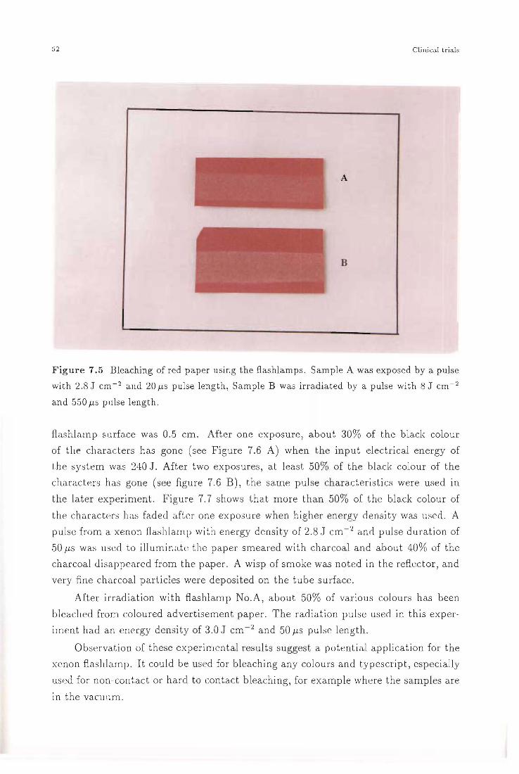
52 ClinicdJ trials
A
B
Figure 7.5 Bleaching of red paper using the ftashlamps. Sample A was exposed by a pulse
with 2.8 J cm- 2 and 20 fl S pulse length, Sample B was irradiated by a pulse with 8 J cm- 2
and 550 flS pulse length.
flashlamp surface was 0.5 cm. After one exposure, about 30% of the black colour
of the cllara.cters has gone (see Figure 7.6 A) when the input electrical energy of
the system was 240.J. After two exposures, at least 50% of the black colour of the
characters has gone (see figure 7.6 B), the same pulse characteristics were used in
the later experiment. figure 7.7 shows that more than 50% of the black colour of
the characters has fadeJ after one exposure when higher energy density was used. A
pulse from a xenon flashla.rnp with energy density of 2.8.J cm- 2 and pulse duration of
50 flS was used to illuminate the paper smeared with charcoal and about 40% of the
charcoal disappeared from the paper. A wisp of smoke was noted in the refiector, and
very fine charcoal particles were deposited on the tube surface.
After irradiation with ftashlamp No.A, about 50% of various colours has been
bleached from coloured advertisement paper. The radiation pulse used in this exper
irnent had an energy density of 3.0.J cm-2 and 50 flS puls~ length.
Observation of these experimental results suggest a potential application for the
xenon fiashlarnp. It could be used for bleaching any colours and typescript, especially
used for non-cont.act or hard to contact bleaching, for example where the samples are
in the vacuum.

7.3. Clinical t.!"i,ds 5.3
A B
F igure 7.6 Bleaching of the black colour of the typescript.
7.3 Clinical trials
7.3.1 Treatment with low energy density and short pulse length
In the first session of clinical tests, we chose flashlamp No.B operating in the original
system. Input electrical energy was 240 J to 303 J. The pulses produced by this system
had 20 f.LS pulse duration and energy density abou t 2 to 2.8 J em -2. The coupling
output aperture was 6 em2 (1 cm x6 cm), and 3 em2 of radiation area was used for the
trials. The distance of the treatment area to the flashlamp surface was 1 cm. There
was no UV filter in this experiment.
The first t st was conducted on normal caucasIan lightly tanned skin on the
forearm of my supervisor. The input electrical energy of 240 J was used. Immediately
after exposure of the skin, the odour of burning hair was smelt and the treated area
appeared white. After 2 hours, heavy erythema appeared and lasted up to about 20
hours, giving a sensation like sunburn. Erythema on the exposure area disappl..>ared
gradually, and the flashed area return to normal after two days.
I have had a blue ink spot tattoo of 0.2 cm in diameter on the left wrist. This
was made by a pen thirty years ago. A 3 cm2 area of asian yellow skin including
the blue spot was exposed to a light pulse, and the input electrical energy was 303 J.
Output energy density was about 2.8 J cm- 2. The immediate response was that the

54 Clinical trjals
Figure 7.7 Bleaching of the black colour of the typescript. Input electrici ty energy of the
syst em was 350 J, the pulse length was 50 J-LS.
exposed area turned grey-white. The blue ink spot was hard to distinguish. One
hour a.fter irradiation, slight erythema appeared and it increased durillg the next 10
hours. Slight ocderna also appeared and sensation like that from a steam burn. After
20 hours, most of the eryth8ma disappeared, but the flashed area could still be seen.
The skin exposed was shiny and t.enner, the blue ink spot looked lighter than that
before exposure. The irradiated area turned to normal within a week after, and the
blue ink spot still persisted.
For latter trial s , Ms Carol Miles and has caucasian skin , was a volunteer. A 3 cm2
tattooed area of the inner leg including red and black tattoo and normal colour skin
was chosen for the clinical trials. The black tattoo has a heavier pigmentation than
that of the red tattoo. An input energy of 303.J was used . The immediate response of
the exposure was that the skin surface appeared grey white. A pricking sensation was
felt, which dissipated in 20 minutes. Very light. erythema and slight oedema occurred
on the treatment day, the erythema and oedema increased over the next 24 hours , and
were associated with trea tment area itches. At 44 hours, we noted that both tattooed
and non-tattoo areas, appeared as at 24 hours , with a little greater response in black
vs clear or red pigmented area.s.
The above ('. xperill1cnt res ults shows that the 20 f-L S pulse with energy density of
7.3. Clinical trials 55
2.8 J cm-2 did not produce lasting damage to the treatment area, and did not affect
the surrounding tissue. As well, the above results indicated that the response of the
exposure to xenon flashlamp in yellow skin is less than that in the white skin. The
response in tattooed areas is greater than that of normal skin, because tattoo pigments
cause tattooed skin to have a greater absorption than normal skin. The above results
suggests that the energy density of the light pulse used was not sufficient to cause
irreversible damage to the pigment clusters.
7.3.2 Clinical trial with long pulse and high energy density
In the second c1inical trial, we chose flashlamp No.A which operated in the modified
system with input electrical energy 800 J, The pulses produced by this system had
a pulse duration of 550 f.ls and a output energy density of 8 J cm -2, a rectangular
aperture of 10mrnx30mm being used.
The treatment area in the inner left leg of the volunteer again included red and
black tattoo and normal skin. Immediately upon exposure the irradiation site became
grey white, and associated with it was an odour of burning hair. This grey white colour
disappeared within 30 minutes. 'Stinging sensation like a mild scald was felt' said the
volunteer. This opaque white appearance of the skin may be caused by the formation
of vacuoles in the dermis probably due to the production of steam, or absorption
of energy by melanin in the epidermis which causes the melanocytes to 'balloon',
the nuclei becoming hyper-chromatic. This effect may increase the scattering of the
incident light.
Three small blisters occurred, all in the tattooed area, and there was erythema
in the non-tattooed area within 24 hours. One blister "Qurst by itself and its area was
squamous, the other two were drained by the volunteer by pricking their edges with
a scalpel blade. The area was bandaged with an elastoplast, after being protected
with an antibiotic ointment containing steroids. Thirty hours after exposure, the
volunteer reported that the treated area exhibited a raised distention about 2.0 mrn
high, 50 mm x 55 mm in area. The response shown was remarkably more intense in
the tattooed skin than in the surrounding skin. The tattoo pigment in tattooed area
absorbed more energy than the surrounding tissue did, just as expected. However, a
550 f.ls pulse length produced excess thermal conduction, so that heavier erythema was
produc~d in non-tattooed skin. Another probable reason for production of erythema
in non tattooed skin is that no UV filter was used.
The distention was gone in 3 days. After 6 days, the exposed area had a light
scab, and healed in 8 days, which indicated that the dermis was not severely damaged.
Two month after treatment, we noted that there was little or no loss of pigment
evident. The skin surface was still shiny and delicate. There was a small amount of
hyper-pigmentation on the exposed un-pigmented skin.

56 Clinical trials
The clinical response to a xenon flashlamp was very close to that of produced
by a Q-switched ruby laser. Scheibner et al described the response to the treatment
of tattoo with a Q-switched ruby laser. Immediately after laser exposure, the skin
turns white and remains this colour for 10 to 20 minutes. The treated area then
turns red and shows some swelling. The treated area will feel like a sunburn for
approximately 30 to 60 minutes. In some patients, vesiculation occurred at sites with
thin skin. Vesicles were replaced generally in 1 to 2 days by a fine crust. The treated
area healed typically within 10 to 14 days, but the skin remained slightly red for an
additional 1 to 3 weeks. The same response also reported by Taylor et al (1990) and
Reid et al (1983).
In our clinical trials on exposed skin our flashlamp gave a very similar response
to the Q-switched ruby laser, which indicates that the energy density of 8 J cm-2 is
very close to the treatment threshold, and indicates that the pulses with 100/ks length
might be useful.

CHAPTER 8
Conclusion
This thesis investigated the mechanism for the favourable results of the Q-switched
ruby laser removal of tattoos. We postulate that this laser works by selective pho
tothermolysis.
This thesis argues that three factors have to be considered for the successful ap
plication of the selective photother~olysis technique. The first condition is a sufficient
spectral match between radiation and targets. The targets must have a greater optical
absorption at the spectral range of the radiation than their surrounding tissue. The
second condition is that the period of energy delivery must be shorter than that of
significant thermal conduction. The third condition is that there is a sufficient energy
density to generate the thermal effects required.
The model of processes for tattoo removal proposed by Reid et al and Taylor et
al, to heat tattoo pigment to generate very high temperature so that conversion of
carbon into carbon monoxide or carbon dioxide, maybe incorrect.
As a results of this studies, a new method for removal of tattoos is proposed. This
thesis report attempts at implementing the method. A high power xenon flashlamp
is employed for the first time as an optical pulse source for a cosmetic purpose. The
expected advantages of this method are the low cost, less than one tenth of the cost of
the Q-switched ruby laser, and good spectrum matching between absorption of tattoo
dyes and radiation from the xenon flashlamp.
Histological studies show that very few tattoo pigment particles are suspended
in the skin, rather the tattoo pigment occurs in small and big clusters. The siz~ of
pigment clusters varies from 1ttm to 20ttm and their distribution in depth is from
0.1 mm to 1 mm. We propose that it is not necessary to rupture individual tattoo
pigment particles, so that a nanosecond order pulse duration for tattoo removal is not
necessary.
Theoretical values for the illumination time and energy intensity required to break
up tattoo pigment clusters are suggested. The pulse duration ought to be less than
57

58 Conclusion
100 JiS. The energy density should be higher than 0.5 J cm-2 when tattoo pigment
clusters are exposed directly.
Absorption spectra for eight tattoo dyes are presented in this thesis. As a result a
very good spectrum match in the visible between the radiation of the xenon flashlamp
and the absorption of the tattoo dyes is revealed. This verifies that the radiation of a
xenon flashlamp satisfies the spectrum matching factor for selective photothermolysis.
As well, a UV filter with high visible light transmission is obtained.
Every effort has been made on the xenon flashlamp system to make the output
characteristic of it to satisfy proposed treatment parameters. In our clinical trials,
the pulses with 20 Its pulse duration and energy density of 2.8 J cm-2 gave a little
greater response in tattooed area than clear skin, and did not affect the surrounding
tissue. The pulse with 550 Its length and 8 J cm-2 gave a more intense response in the
tattooed area than its surrounding tissue, but erythema occurred in the non-tattooed
skin area. The pulses, with short pulse length and low energy or with long pulse
length and high energy, did not produce lasting damage to the treatment area. The
response of the treatment area immediately and some hours after was very close to
that produced by the Q-switched ruby laser.
The results of our theoretical calculation and clinical trials suggested that pulses
of the order of 100 microsecond are available for the treatment of tattoos without
damage to the tattooed area and its surrounding tissue. They also suggested that
energy density of 8 J cm-2 is probably near the treatment threshold for pulses of this
length.
We have asked Xenon Corp. to provide high fill pressure xenon flashlamps with
thicker wall. This should allow us to produce the pulses with 10 J cm-2 and 100 JiS.
As a result of the theoretical work and clinical trials, and experience with the
Q-switched ruby laser removal of tattoos, we are hopeful that such pulses will treat
professional tattoos with the same effectiveness as the Q-switched ruby laser, namely
substantial lightening or complete fading of a tattoo after 3 to 8 treatments.

Acknowledgements
I would like to thank all persons and organisations who supported me during my work
for this thesis.
The patience and excellent guidance of my supervisor Assoc. Prof. P. H. Butler is
. greatly appreciated. His continuous encouragement and personal interest provided a
strong foundation for the skills and techniques I learnt in the course of this thesis. I
have not only gained a knowledge of Medical Physics but a new insight into values of
life as well.
My sincere thanks go to Medical Laser Developments Ltd who provided me with
a scholarship for my years study.
I have to thank my husband, Ziyuan, my son, Ben, and other family members
who have been a continual source of encouragement and support without which it
would not have possible for me to carry through this study.
I would like to coming special thanks to Dr. R. Bennett for his valuable suggestion
during the modification of the xenon flashlamp system, and also for his patience in
helping with the proofreading of the English of this thesis.
My special thanks also go to Ms Carol Miles for her support and enthusiasm
throughout this project, which have been invaluable.
I would like to thank the members of the staff and students of the Physics and
Astronomy Department who have helped me, Particularly
Gill Evans, Mary KInnaird and Beverly Bristowe for their love and care during
my stay in this department.
Cindy Lienert, Derek Smithies and Peter Wells for their great help and valuable
discussion. I very much appreciate the help that Cindy give me in overcoming many
many problems in English language and computer work and the hospitality she gave
me.
Clive Rowe, Stephen Hemmingsen, Bruce Bradshaw, Mark Aitchison and Ross
Ritchie for their support and lots of practical help.
Dr. P. Broady of the Department of 'Plant and Microbial Sciences for his help
with the histology study.
Mr. B. Reid of Chemistry Department for his help with the spectrum measure
ments.
THE UeRARY UNIVER$JTY OF CANTERBURY
OHRISTCHURCH, N.Z.
59
References
Abel E A, Inga S, and Dannette Q 1972 Studies of chronic inflammation in a red tattoo by electron microscopy and histochemistry Acta Dermatovener (Stockholm) 52 453-461
Agris J 1977 Tattoos in women Plastic (3 Reconstructive Surgery 60 22-37
Anderson R R and Parrish J A 1981 The optics of human skin The Journal of Investigative Dermatology 77 13-19
Apfelberg D B and Manchester G H 1987 Decorative and traumatic tattoo biophysics and removal Clinics in Plastic Surgery 14243-251
Apfelberg D B, Maser M R, Lash H, White D N, and Flores J T 1985 Comparison of argon and carbon dioxide laser treatment of decorative tattoos: A preliminary report Annals of Plastic Surgery 14 6-15
Apfelberg D B and Maser M R 1979 Argon laser treatment of decorative tattoos British Journal of Plastic Surgery 32 141-144
Apfelberg D B, Laub DR, Maser M R; and Lash H 1980 Pathophysiology and treatment of decorative tattoos with reference to argon laser treatment Clinics in Plastic surgery 7 369-377
Brady S C, Blokmanis A, and Jewett L 1979 Tattoo removal with the carbon dioxide laser Annals of Plastic Surgery 2 482~490
Carruth J A S and Mckenzie A L 1986 Medical Lasers Medical Science Series(Bristol, England: Adam Hilger Ltd)
Clabaugh W A 1975 Tattoo removal by superficial dermabrasion Plastic (3 reconstructive surgery 55 401-405
Dishington R H, Hook W R, and Hilberg R P 1974 Flashlamp discharge and laser efficiency Applied Optics 13 2300-2312
Dismukes D 1986 The "chemo-Iaser" technique for the treatment of decorative tattoo: A more complete dye-removal procedure Lasers in Surgery and Medicine 6 59-61
Emmett J Land Schawlow A L 1964 Direct measurement of xenon flashtube opacity Journal of Applied Physics 35 2601-2604
Everett P N, Aldag H R, Ehrlich J J, Janes G S, Klimek D E, LandersF M, and Pacheco D P 1986 Efficient 7-J flashlamp-pumped dye laser at 500-nm wavelength Applied Optics 25 2142-2147
Goldman L, Blaney D J, Kindel D J, Richfield D, and Franke E K 1963 Pathology of the effect of the laser beam on the skin Nature 197 912
Goldman L, Hornby P, and Meyer R 1965 Radiation from a Q-switched ruby laser with a total output of 10 megawatts on a tattoo of man J Invest Derm 44 69
Goldman L, Rockwell R J, Meyer R, Otten R, and Wilson R G 1967 Laser treatment of
60

tattoos Journal of the American Medical Association 201 163-166
Halewyn C N V 1987 Laser treatment of port wine stains Msc thesis University of Canterbury
Hudson D A and Lechtape-Gruter R U 1990 A simple method of tattoo removal South African Medical Journal 78 748-749
ILC Technology 399 Java Drive, Sunnyvale, California 94089, USA 1986 An overview of jlashlamps and cw arc lamps
Kuban A K, Morrison P R, Trainor S W, and Tan 0 T 1992 Pulse duration effects on cutaneous pigment Lasers in Surgery and Medicine 12 282-287
Lehmann G and Pierchalla P 1988 Tattooing dyes Dermatoser in Becuf and Umwelt 36 152-156
Lindsay D G 1989 Tattoos Dermatologic Therapy 7 147-153
Loewenthal L J A 1960 Reactions in green tattoos Archives of Dermatology 82 129-131X
Lue J T, Song D Y, and Yeh C K 1980 The plasma Z-pinch effect on the I-V characteristic of fast discharge flash tubes Journal Applied Physics 51 4626-4630
Marotta A and Galvao R M 0 1978 Anomalous plasm resistivity in prepulsed flashlamp discharges Applied Physics 33 280-281
National Health and Medical Research Council 1989 Occupational standard for exposure to ultraviolet radiation Radiation Health Series No. 29 Published by the Australian Radiation Laboratory on behalf of the National Health and Medical Research Council
Pickering J W 1990 Modelling the laser treatment of vascular lesions Phd thesis University of Canterbury
Pickering J W, Butler P H, Ring B J, and Walker E P 1989a Thermal profiles of blood vessels heated by a laser Australasian Physical and Engineering Sciences in Medicine 12 11-15
--- 1989b Computed temperature distribution around ectatic capillaries exposed to yellow(578nm) laser light Physics in Medicine and Biology 34 1247-1258
Rasiah I J, Tan B C, and Lee H W 1991 Voltage-current relationship for flashlamps: an empirical approach Applied Optics 30 485-488
Reid Rand Muller S 1980 Tattoo removal by C02 laser dermabrasion Plastic and Reconstructive Surgery 65 717-728
Reid W H, Mcleod P J, Ritchie A, and Fergu~on-Pell M 1983 Q-switched ruby laser treatment of black tattoos British Journal of Plastic Surgery 36 455-459
Reid W H, Miller I D, Murphy M J, Paul J P, and Evans J H 1990 Q-switched ruby laser treatment of tattoos; a 9-year experience British Journal of Plastic Surgery 43 663-669
61

Scheibner A, Kenny G, White W, and Wheeland R G 1990 A superior method of tattoo removal using the Q-switched ruby laser Journal of Dermatological Surgery 12:16 1091-1098
Scheuplein R J 1964 A survey of some fundamental aspects of the absorption and reflection of light by tissue Journal of the society of Cosmetic Chemists 15 111-122
Scutt R W B 1972 The chemical removal of tattoos British Journal of Plastic Surgery 25 189-194
Silberberg I and Leider M 1970 Studies of a red tattoo Archives of Dermatology 101 299-304
Slater D N and Durrant T E 1984 Tattoo: light and transmission electron microscopy studies with X-ray microanalysis Clinical and Experiment Dermatology 9 167-173
. Spaulding & Rogers MFG. Route 85, New Scotland Road Voorheesville, New York 1988 Tattoo supply
Spaulding & Rogers MFG. Route 85, New Scotland Road Voorheesville, New York 1989-1990 Catalog supplement
Spaulding & Rogers MFG. Route 85, New Scotland Road Voorheesville, New York 1991-1992a Catalog supplement
Taylor C R, Grange R W, Dover J S, Flotte T J, Gonzalez E, Michaud N, and Anderson R R 1990 Treatment of tattoos by Q-switched ruby laser Archives of Dermatology 126893-899
White W 1992a Private communication
--- 1992b Photographed record of Q-switched ruby laser treatment unpublished
Wood E J and Bladon P T 1985 The Human Skin The Institute of Biology's studies in Biology no.164(London: Edward Arnold Ltd)
Xenon Corporation 20 Commerce Way, Woburn, MA 018011992b Service Manual
62


![Blue-Green Lasers and Electrodeless Flashlamps Lasers and Electrodeless Flashlamps F. W. Perkins CIAM * Accesion For7 DTIC TAB [] Urnannouriced lI Justification By Dist ibutio.. August](https://static.fdocuments.net/doc/165x107/5ab786897f8b9a684c8b991e/blue-green-lasers-and-electrodeless-flashlamps-lasers-and-electrodeless-flashlamps.jpg)