High Output, Pancake Style Tension/Compression Load...
34
LO-2 High Output, Pancake Style Tension/Compression Load Cells Models 41a, 75a ZERO & SPAN ADJUSTMENTS WELDED STAINLESS STEEL Dimensions Mtg. Center Available Ranges Available Ranges Dia. Ht. Hole ID Thread A" B" C" 50; 100; 250; 500; 1000 lbs. 50; 100; 250; 500 lbs. 3.00 1.00 0.28" 3/8-24UNF 2.5 0.9 1.8 2000; 3000; 4000; 5000 lbs. 1000; 2000 lbs. 3.50 1.00 0.34" 1/2-20UNF 2.5 0.9 1.8 7500; 10,000; 15,000 lbs. 3000; 4000; 5000; 7500 lbs. 5.50 1.80 0.40" 1-14UNS 2.3 1.5 2.0 20,000; 30,000; 50,000 lbs. 10,000; 15,000; 20,000 lbs. 6.00 1.80 0.53" 1-1/2-12UNF 2.3 1.5 2.0 Specify Output: Output/Options Voltage/Option Current/Option Enhancement Options See pages AP-6 & 7 for details 0 – 5 Vdc/2c 4-20mA/2k (2 wire) Remote Shunt calibration/3d 0 – 10Vdc/2t 4-20mA/2j (3 wire) Model 41a Model 75a (Order Code AL141) (Order Code BL175) Precision Fatigue Rated PERFORMANCE ENVIRONMENTAL ELECTRICAL MECHANICAL Model 41a Model 75a Order Code AL141 Order Code BL175 Ranges ......................................... 0-50 to 50,000 lbs.* 0-50 to 20,000 lbs. Accuracy Non-linearity ............................. –0.1% F.S. –0.1% F.S. Hysteresis................................. –0.08% F.S. –0.1% F.S. Non-repeatability ...................... –0.03% F.S. –0.03% F.S. Outputs ......................................... See below Operating Temperature Range .... 0 F to 185 F 0 F to 185 F Compensated Temperature Range 60 F to 160 F 60 F to 160 F Temperature Effects on Zero and Span ...................................... –0.005% F.S./ F –0.005% F.S./ F Electrical Termination ................... PTIH-10-6P Welded Stainless Hermetic Connector Mating Connector Order Code AA111 Life Cycles (approx) ..................... 10 7 fully reversed 10 9 fully reversed Operation...................................... Tension/Compression Tension/Compression Casing Material ............................ Welded Stainless Steel Welded Stainless Steel Notes * Special ranges available from 5 to 500,000 lbs. Standard calibration for tension/compression load cells is in tension only. Model 41a & Model 75a high output pancake style load cells have the same features as the Models 41 & 75 Tension & compression Cells with hermetically sealed, all welded stainless steel construction and high resistance to side loads. The added feature of an internal amplifier for voltage or current output reduces the effects of signal noise, and eliminates the need in most cases for a signal conditioning card in ones data acquisition system. Options include cer- tifications for use in hazardous areas, an internal buffered shunt calibration circuit for ease of set-up with an associated indicator, and the removal of zero & span adjustments. w w w.sensotec.com 1-800-848-6564 w w w.honeywell.com/sensing Sensotec Sensors
Transcript of High Output, Pancake Style Tension/Compression Load...
LO-2
High Output, Pancake StyleTension/Compression Load CellsModels 41a, 75a
ZERO & SPAN ADJUSTMENTS
WELDED STAINLESS STEEL
Dimensions
Mtg. CenterAvailable Ranges Available Ranges Dia. Ht. Hole ID Thread A" B" C"50; 100; 250; 500; 1000 lbs. 50; 100; 250; 500 lbs. 3.00 1.00 0.28" 3/8-24UNF 2.5 0.9 1.82000; 3000; 4000; 5000 lbs. 1000; 2000 lbs. 3.50 1.00 0.34" 1/2-20UNF 2.5 0.9 1.87500; 10,000; 15,000 lbs. 3000; 4000; 5000; 7500 lbs. 5.50 1.80 0.40" 1-14UNS 2.3 1.5 2.020,000; 30,000; 50,000 lbs. 10,000; 15,000; 20,000 lbs. 6.00 1.80 0.53" 1-1/2-12UNF 2.3 1.5 2.0
Specify Output:Output/Options Voltage/Option Current/Option Enhancement OptionsSee pages AP-6 & 7 for details 0 – 5 Vdc/2c 4-20mA/2k (2 wire) Remote Shunt calibration/3d
0 – 10Vdc/2t 4-20mA/2j (3 wire)
Model 41a Model 75a(Order Code AL141) (Order Code BL175)Precision Fatigue Rated
PERFORMANCE
ENVIRONMENTAL
ELECTRICAL
MECHANICAL
Model 41a Model 75aOrder Code AL141 Order Code BL175
Ranges......................................... 0-50 to 50,000 lbs.* 0-50 to 20,000 lbs.AccuracyNon-linearity ............................. –0.1% F.S. –0.1% F.S.Hysteresis................................. –0.08% F.S. –0.1% F.S.Non-repeatability ...................... –0.03% F.S. –0.03% F.S.
Outputs......................................... See below
Operating Temperature Range .... 0 F to 185 F 0 F to 185 FCompensated Temperature Range 60 F to 160 F 60 F to 160 FTemperature Effects on Zeroand Span...................................... –0.005% F.S./ F –0.005% F.S./ F
Electrical Termination................... PTIH-10-6P WeldedStainless Hermetic Connector
Mating Connector Order Code AA111
Life Cycles (approx) ..................... 107 fully reversed 109 fully reversedOperation...................................... Tension/Compression Tension/CompressionCasing Material ............................ Welded Stainless Steel Welded Stainless Steel
Notes * Special ranges available from 5 to 500,000 lbs.Standard calibration for tension/compression load cells is in tension only.
Model 41a & Model 75a high output pancake style load cells have the same features as theModels 41 & 75 Tension & compression Cells with hermetically sealed, all welded stainlesssteel construction and high resistance to side loads. The added feature of an internal amplifierfor voltage or current output reduces the effects of signal noise, and eliminates the need inmost cases for a signal conditioning card in ones data acquisition system. Options include cer-tifications for use in hazardous areas, an internal buffered shunt calibration circuit for ease ofset-up with an associated indicator, and the removal of zero & span adjustments.
w w w.sensotec.com1-800-848-6564
www.honeywell.com/sensing
Sens
otec
Sen
sors
LOA
DU
LTRA
PREC
ISION
& FA
TIGU
E RA
TED
LO-3
ZERO & SPAN ADJUSTMENTS
TENSION & COMPRESSION
Dimensions
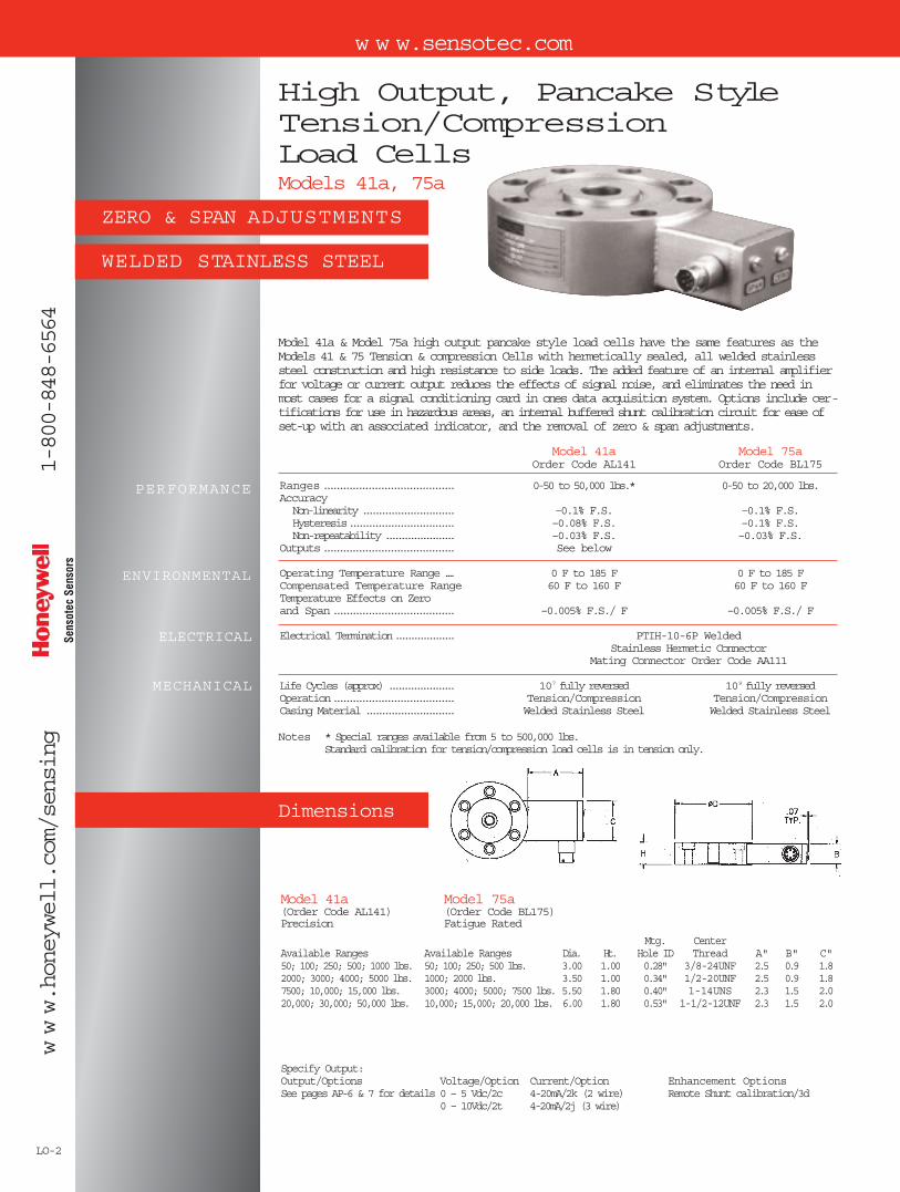
High Output Ultra Precision &Fatigue Rated Load CellsModels 45a, 47a
Model 45a & Model 47a high output ultra precision & fatigue rated load cells include all the featuresand the industry common dimensions of the Model 45 & Model 47 plus a high level voltage or currentoutput. The high level output reduces the effects of signal noise, and in most cases, eliminates theneed for an additional signal conditioning card in ones data acquisition system. Options include certifi-cations for use in hazardous areas, an internal buffered shunt calibration circuit for ease of setup withan associated indicator, and the removal of zero & span adjustments. The standard calibration is in ten-sion, and optional data is available for both tension and compression.
PERFORMANCE
ENVIRONMENTAL
ELECTRICAL
MECHANICAL
Model 45a Model 47aOrder Code AL145 Order Code AL147
Ranges ................................... 0-200 to 0 to 100,000 lbs. 0-200 to 0-100,000 lbs.Accuracy (Static Error Band) .......... ±0.04% F.S. to ±0.06% F.S. ±0.02% F.S. to ±0.05% F.S.Output Options .......................... See Below (calibrated in tension) See Below (calibrated in tension)
Operating Temperature Range ....... 0°F to 185°FTemperature Effects on Zero & Span±0.01%F.S./°F
Electrical Termination ................. PT1H-10-6P welded stainless steel hermetic connectorMating Connector Order Code AA111
Operation................................. Tension/CompressionLife Cycles (approximately)........... One Billion, Fully ReversedCase Material ........................... Welded Stainless Steel
Range O.D." H" Center Thread Clearance Holes for Mounting200; 500; 1000; 250; 5000; lbs. 4.12 1.37 5/8-18 UNF-3B 9/32 Dia., 8 Holes Eq. Sp., 3.50 B.C.10,000-25,000 lbs. 6.06 1.75 1-1/4-12 UNF-3B 13/32 Dia., 12 Holes Eq. Sp., 5.125 B.C.50,000 lbs. 8.00 2.50 1-3/4-12 UNF-3B 17/32 Dia., 16 Holes Eq. Sp., 6.50 B.C.100,000 lbs. 11.00 3.50 2-3/4-8 UNF-3B 11/16 Dia., 16 Holes Eq. Sp., 9.00 B.C.
Specify Output:Output/Options Voltage/Option Current/Option Enhancement OptionsSee pages AP-6 & 7 for details 0 ± 5 Vdc/2c 4-20mA/2k (2 wire) Remote Shunt calibration/3d
0 ± 10Vdc/2t 4-20mA/2j (3 wire)
NOTE: Standard calibration for tension/compression load cells is in tension only.
Model 45a Fatigue Rated(Order Code AL145)
Range O.D." H" Center Thread200; 500; 1000; 2500; 5000 lbs. 4.12 2.5 5/8-18 UNF-3B10,000-25,000 lbs. 6.06 3.5 1-1/4-12 UNF-3B50,000 lbs. 8.00 4.5 1-3/4-12 UNF-3B100,000 lbs. 11.00 6.5 2-3/4-8 UNF-3B
Model 47a Ultra Precision Fatigue Rated(Order Code AL147) Includes Factory Installed Base Plate
1-800-848-6564

LO-4
High Output Pancake StyleCompression Load CellsModels 43a, 73a
Dimensions
WELDED STAINLESS STEEL
ZERO & SPAN ADJUSTMENTS
Model 43a & Model 73a high output compression type load cells include all the features of theModels 43 & 73 plus the option of either voltage or current output. These load cells are of allwelded stainless steel construction with hermetic welded-on electrical connectors. The highlevel –5, 10 Vdc or 4-20mA outputs are standard with zero and span adjustments with gasketedcap screw covers. Options include certifications for use in hazardous area, an internal bufferedshunt calibration circuit for ease of set-up with an associated indicator, and the removal of zero& span adjustments for tamper free installations, and a variety of electrical terminations.
PERFORMANCE
ENVIRONMENTAL
ELECTRICAL
MECHANICAL
Model 43a Model 73aOrder Code AL143 Order Code BL173
Ranges*........................................ 0-50 to 0-200,000 lbs. 0-50 to 0-100,000 lbs.AccuracyNon-linearity ............................. –0.1% F.S. –0.1% F.S.Hysteresis................................. –0.08% F.S. –0.1% F.S.Non-repeatability ...................... –0.03% F.S. –0.03% F.S.
Outputs......................................... See Below
Operating Temperature Range .... 0 F to 185 FTemperature Effects on Zero & Span –0.01%F.S./ F
Electrical Termination................... PTIH-10-6P or equiv. (Hermetic stainless)Mating Connector Order Code AA111
Operation...................................... 108, Undirectional 109, UnidirectionalCase Material ............................... Welded Stainless Steel Welded Stainless Steel
*Special Ranges available from 5 to 500,000 lbs. Contact Sensotec sales for details.
Model 43a Model 73aPrecision Fatigue Rated
Load Three Clearance HolesButton for Mounting* Socket
Available Ranges Available Ranges Dia. Ht. Dia. Head Cap Screws50; 100; 250; 500; 1000 lbs. 50; 100; 250; 500 lbs. 3.00 1.18 0.56" 1/4
*3.0 dia. cell has 6 mounting holes
2000; 3000; 4000; 5000 lbs. 1000; 2000 lbs. 3.50 1.18 0.69" 5/16"7500; 10,000; 15,000; 3000; 4000; 5000; 4.50 2.00 1.50" 3/8"20,000; 30,000; 50,000; 7500; 10,000; 15,000; 4.50 2.00 1.50" 3/8"75,000; 100,000 lbs. 20,000; 30,000; 50,000 lbs. 4.50 2.00 1.5" 3/8"150,000; 200,000 lbs. 75,000; 100,000 lbs. 5.50 2.50 2.00" 3/8"
Specify Output:Output/Options Voltage/Option Current/Option Enhancement OptionsSee pages AP-6 & 7 for details0 – 5 Vdc/2c 4-20mA/2k (2 wire) Remote Shunt calibration/3d
0 – 10Vdc/2t 4-20mA/2j (3 wire)
w w w.sensotec.com1-800-848-6564
www.honeywell.com/sensing
Sens
otec
Sen
sors
LO
AD
HIG
H O
UT
PU
T
LO-5
ALL WELDED STAINLESS STEEL
ZERO & SPAN ADJUSTMENTS
High Output Rod End/In-lineTension Type Load CellsModels RMa, RHa, RFa
Dimensions
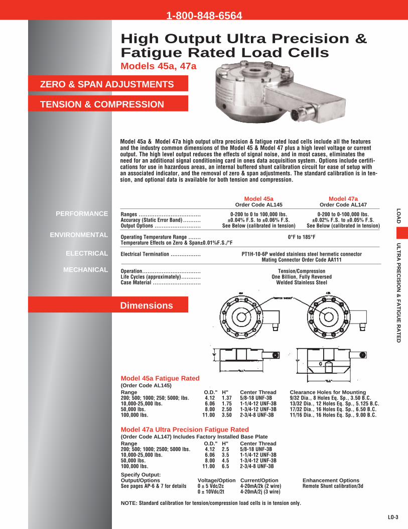
Model RMa, with outside threads, Model RHa with both inside and outside threads, and theModel RFa with inside threads are all High Output Rod End Load Cells designed to be mountedin-line to the load axis to measure tension. The outputs for these load cells are +/-5 or 10 Vdc,or 4-20mA (two wire) all calibrated in tension. The mounting thread configurations and the allwelded stainless steel construction make these tension load cells ideal for a variety of ruggedfield applications as well as in the laboratory. Options include removal of zero & span adjust-ments for tamper free installations and a variety of electrical terminations. The high output signaloffers resistance to electrical noise as well as additional signal resolution. Additional optionsinclude certifications for use in hazardous areas, an internal buffered shunt calibration circuit forease of setup with an associated indicator, and a variety of thread selections, including metricsizes.
PERFORMANCE
ENVIRONMENTAL
ELECTRICAL
MECHANICAL
Model RMa Model RHa Model RFa
OD OD ODRanges: 0-2000 to 0-4000 lbs. .... AL613 1.50 AL619 1.50 AL614 1.50
0-7500 to 0-20,000 lbs. . AL615 1.75 AL620 1.75 AL616 1.750-20,000 to 50,000 lbs. . AL617 2.50 AL624 2.50 AL618 2.50
Operation...................................... Calibrated in TensionLinearity & Hysteresis .................. +/-0.2%F.S.Repeatability................................. +/-0.05%F.S.Output Options ............................. See Below
Operating Temperature Range .... 0°F to 185°FTemperature Effects on Zero & Span +/-0.01%F.S./°F
Electrical Termination PTIH-10-6P Welded Stainless Hermetic ConnectorMating Connector AA111
Case Materal ................................ All Welded Stainless Steel Construction
RFa RHa
RMa
Specify Output:Voltage/Option Current/Option
0 ± 5 Vdc/2c 4-20mA/2k (2 wire)0 ± 10Vdc/2t4-20mA/2j (3 wire)
1-800-848-6564

LO-36
www.sensotec.com1-
800-
848-
6564
ww
w.h
on
eyw
ell.c
om
/sen
sin
g
ULTRA PRECISION 0.02%
DESIGNED AS CALIBRATIONREFERENCE STANDARDS
ULTRA HIGH STABILITY
OPTIONALASTM E74 CALIBRATION
Imperial Class Tension &Compression Load CellsModel IC48
Sensotec’s Calibration Class ultra high accuracy load cells are calibrated and traceable toNIST. These stainless steel hermetically sealed rugged standards are designed for use in themetrology lab and as reference standards when calibrating other load cells. The Model 48load cells are designed for low creep, high stability and high immunity to eccentric loads. Theload cell comes complete with a factory installed pull plate and a calibration adaptor to ensurehigh repeatability when using the load cell in a test frame.
Range D" H" L” T1" T2"
500 4.13 4.38 .75 5/8-18 UNF-3A 5/8-18 UNF-3B
1,000 4.13 4.38 .75 5/8-18 UNF-3A 5/8-18 UNF-3B
2,000 4.13 4.38 .75 5/8-18 UNF-3A 5/8-18 UNF-3B
5,000 4.13 4.38 .75 5/8-18 UNF-3A 5/8-18 UNF-3B
10,000 6.06 6.38 1.50 1-1/4-12 UNF-3A 1-1/4-12 UNF-3B
25,000 6.06 6.38 1.50 1-1/4-12 UNF-3A 1-1/4-12 UNF-3B
50,000 8.00 8.25 2.00 1-3/4-12 UNF-3A 1-3/4-12 UNF-3B
100,000 11.00 9.75 2.50 2-3/4-8 UNF-3A 2-3/4-8 UNF-3B
Model 48Order Code AL121
Sen
sote
c S
enso
rs

LO
AD
CA
LA
BR
AT
ION
ST
AN
DA
RD
LO-37
1-800-848-6564
General Information
Range* .........................................
Output, standard (mV/V)** ...........Static error band (±% F.S.)1 .........Non-Linearity (±% F.S.)2 ..............Hysteresis (±% F.S.)2 ...................Non-Repeatability (±% F.S.)2 .......Creep, 20 min (%) ........................Eccentric Load Sensitivity (±% /in.)
Temperature, Operating ...............Temperature, Compensated ........Temperature Effect
– Zero (max).............................– Span (max)............................
Excitation, Calibrated (VDC) ........Bridge Resistance, nominal .........Zero Balance (±% F.S.)................Insulation Resistance ...................Wiring Code Standard..................Electrical Termination...................Mating Connector (optional) .........
Deflection @ Full Scale (in) .........Static Overload Capacity (±% F.S.)Ringing Frequency (kHz) .............Weight (lbs) ..................................
-65° to 200° F30° to 130° F
.0008
.0008
103500.5
5000 @ 50 VDC#39 see appendixMS3112E-12-8PMS3116A-12-8S
PERFORMANCE
ENVIRONMENTAL
ELECTRICAL
MECHANICAL
General Information
Typical System Configuration
500*, 1000, 10,0002000 5,000 25,000 50,000 100,0002.0 2.0 2.0 2.0 2.0
0.02 0.03 0.03 0.03 0.050.02 0.03 0.04 0.04 0.050.02 0.04 0.04 0.05 0.05
0.005 0.005 0.005 0.005 0.0050.01 0.01 0.01 0.01 0.010.1 0.1 0.1 0.1 0.1
0.001 0.002 0.002 0.002 0.002300 300 300 300 300
2.4,3.4,6.8 9.1 5.7,7.0 6.3 4.57 7 22 48 133
* Other size/range/output configurations available. Consult factory.** 500 lb range has 700 Ohm bridge resistance
1. Static error band is the guaranteed performance specification.The static error band is calculated as the best fit straight line through zero, including the effects of non-linearit, hysteresis and non-repeatability.
2. Values noted are typical values but fall within the static error band. Removal of these components may invalidate calibration.
3. Off-axis loading maximum allowable 50% of F.S.
For the Imperial Class Model IC48 the load cell and pull plate are calibrated as a unit.
Options: Calibration types: ASTME74, tension (standard), tension & compression or compression only.
Typical system set up showing signal conditioning and display unit calibrated as a system withthe load cell. Also shown is a laptop computer running Sensotec load cell calibration software.
LO-6
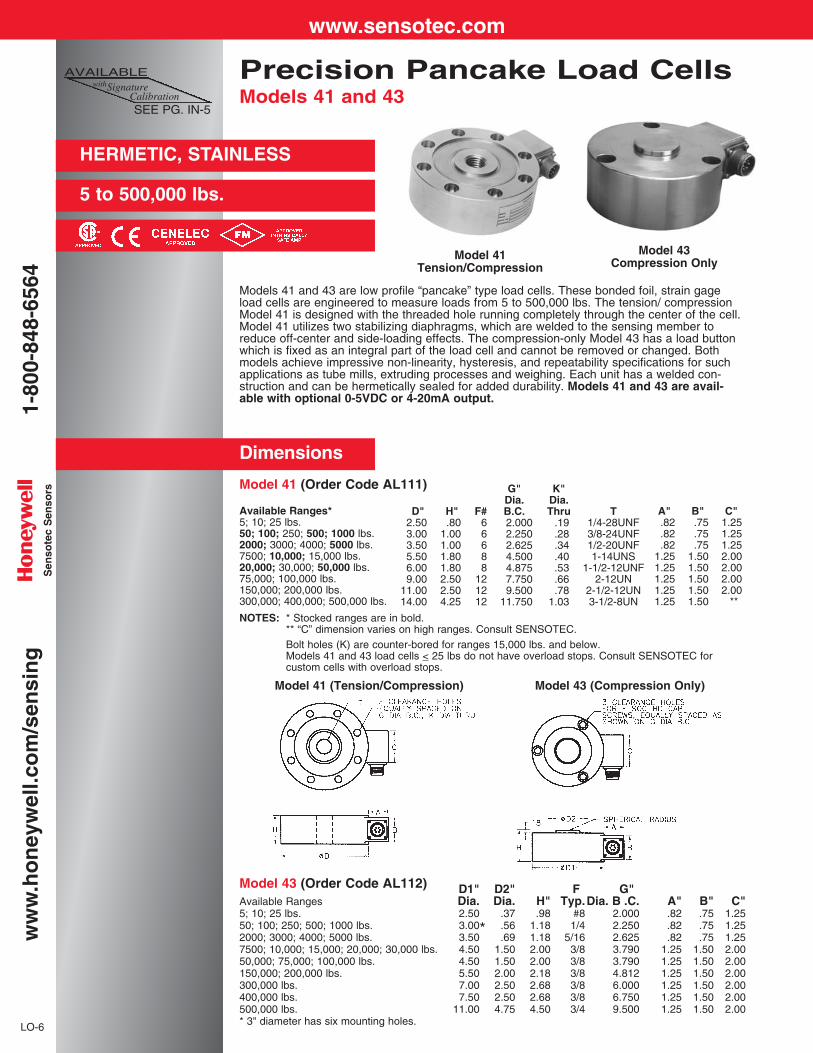
Models 41 and 43 are low profile “pancake” type load cells. These bonded foil, strain gageload cells are engineered to measure loads from 5 to 500,000 lbs. The tension/ compressionModel 41 is designed with the threaded hole running completely through the center of the cell.Model 41 utilizes two stabilizing diaphragms, which are welded to the sensing member toreduce off-center and side-loading effects. The compression-only Model 43 has a load buttonwhich is fixed as an integral part of the load cell and cannot be removed or changed. Bothmodels achieve impressive non-linearity, hysteresis, and repeatability specifications for suchapplications as tube mills, extruding processes and weighing. Each unit has a welded con-struction and can be hermetically sealed for added durability. Models 41 and 43 are avail-able with optional 0-5VDC or 4-20mA output.
Available Ranges*5; 10; 25 lbs.50; 100; 250; 500; 1000 lbs.2000; 3000; 4000; 5000 lbs.7500; 10,000; 15,000 lbs.20,000; 30,000; 50,000 lbs.75,000; 100,000 lbs.150,000; 200,000 lbs.300,000; 400,000; 500,000 lbs.
G"Dia.B.C.2.0002.2502.6254.5004.8757.7509.500
11.750
K"Dia.Thru
.19
.28
.34
.40
.53
.66
.781.03
A".82.82.82
1.251.251.251.251.25
B".75.75.75
1.501.501.501.501.50
C"1.251.251.252.002.002.002.00
**
T1/4-28UNF3/8-24UNF1/2-20UNF1-14UNS
1-1/2-12UNF2-12UN
2-1/2-12UN3-1/2-8UN
D"2.503.003.505.506.009.00
11.0014.00
H".80
1.001.001.801.802.502.504.25
F#66688
121212
Precision Pancake Load CellsModels 41 and 43
Dimensions
Model 41 (Order Code AL111)
HERMETIC, STAINLESS
5 to 500,000 lbs.
Model 43 (Order Code AL112) D1" D2" F G"Available Ranges Dia. Dia. H" Typ.Dia. B .C. A" B" C"5; 10; 25 lbs. 2.50 .37 .98 #8 2.000 .82 .75 1.2550; 100; 250; 500; 1000 lbs. 3.00 .56 1.18 1/4 2.250 .82 .75 1.252000; 3000; 4000; 5000 lbs. 3.50 .69 1.18 5/16 2.625 .82 .75 1.257500; 10,000; 15,000; 20,000; 30,000 lbs. 4.50 1.50 2.00 3/8 3.790 1.25 1.50 2.0050,000; 75,000; 100,000 lbs. 4.50 1.50 2.00 3/8 3.790 1.25 1.50 2.00150,000; 200,000 lbs. 5.50 2.00 2.18 3/8 4.812 1.25 1.50 2.00300,000 lbs. 7.00 2.50 2.68 3/8 6.000 1.25 1.50 2.00400,000 lbs. 7.50 2.50 2.68 3/8 6.750 1.25 1.50 2.00500,000 lbs. 11.00 4.75 4.50 3/4 9.500 1.25 1.50 2.00* 3" diameter has six mounting holes.
*
NOTES: * Stocked ranges are in bold.** “C” dimension varies on high ranges. Consult SENSOTEC.Bolt holes (K) are counter-bored for ranges 15,000 lbs. and below.Models 41 and 43 load cells < 25 lbs do not have overload stops. Consult SENSOTEC forcustom cells with overload stops.
AVAILABLEwithSignature
CalibrationSEE PG. IN-5
Model 41 (Tension/Compression) Model 43 (Compression Only)
Model 41Tension/Compression
Model 43Compression Only
www.sensotec.com1-
800-
848-
6564
ww
w.h
on
eyw
ell.c
om
/sen
sin
gS
enso
tec
Sen
sors

Model 41 Model 43(Tension/Compression) (Compression only)
Order Code AL111 Order code AL112
5 to 500,000 lbs. 5 to 500,000 lbs.
±0.2% F.S. ±0.2% F.S.±0.1% F.S. ±0.1% F.S.
±0.1% F.S. ±0.1% F.S.±0.08% F.S. ±0.08% F.S.
±0.1% F.S. ±0.1% F.S.±0.03% F.S. ±0.03% F.S.
2mV/V 2mV/V3mV/V 3mV/VInfinite Infinite
-65° F to 250° F -65° F to 250° F60° F to 160° F 60° F to 160° F
.002% F.S./° F .002% F.S./° F.002% Rdg./° F .002% Rdg./° F
Bonded foil Bonded foil10VDC 10VDC
Up to 15VDC or AC Up to 15VDC or AC5000 megohms @ 50VDC 5000 megohms @ 50VDC
350 ohms 350 ohmsIncluded Included
#2 (See P. AP-8) #2 (See Pg. AP-8)
PTIH-10-6P or equiv. PTIH-10-6P or equiv.(Hermetic stainless) (Hermetic stainless)
MS3102E-14S-6P or equiv. MS3102E-14S-6P or equiv.
PT06A-10-6S or equiv. PT06A-10-6S or equiv.MS3106A-14S-6S or equiv. MS3106A-14S-6S or equiv.
50% over capacity 50% over capacitySee “T” Dimension Info N/A
See table below See table below.003" .003"
17-4PH Stainless 17-4PH Stainless4340 Painted 17-4PH Stainless
±5VDC, 4-20mA 0-5VDC, 4-20mA
Load Ranges...............................Non-Linearity (max)
5 to 25 lbs. ................................50 to 500,000 lbs. .....................
Hysteresis (max)5 to 25 lbs. ................................50 to 500,000 lbs. .....................
Non-Repeatability (max)5 to 25 lbs. ................................50 to 500,000 lbs. .....................
Output (standard)5 to 25 lbs. ................................50 to 500,000 lbs. .....................
Resolution ...................................
Temperature, Operating..............Temperature, Compensated .......Temperature Effect
- Zero (max) ............................- Span (max) ...........................
Strain Gage Type........................Excitation (calibration).................Excitation (acceptable)................Insulation Resistance..................Bridge Resistance.......................Shunt Calibration Data................Wiring Code (std) ........................Electrical Termination (std)
5 to 5000 lbs ...........................
7500 to 500,000 lbs ................Mating Connector (not incl.)
5 to 5000 lbs ...........................7500 to 500,000 lbs ................
Static Overload Capacity ............Thread Size.................................Maximum Extraneous Forces
without damage.......................Deflection—Full Scale.................Casing Material
5 to 200,000 lbs ......................300,000 to 500,000 lbs ...........
Outputs Available........................
How to order (See Pg. AP-19)Load cell selection flow chart (see Pg. LO-1)
PERFORMANCE
ENVIRONMENTAL
ELECTRICAL
MECHANICAL
INTERNALLY AMPLIFIEDUNITS* (Optional)
General Information
LO-7
LO
AD
PR
EC
ISIO
N
Temperature compensated 1b, 1c, 1d, 1e, 1f; Int. shunt cal 8a; Special calibration (Model 41) 30a, 30b;Signature calibration 53e
Premium Options: 1i; 2a (Model 43≥50 lbs.), 2b (Model 41≥50 lbs.), 2j, 2N, 2q; 3a, 6a (≥ 5000 lbs.), 6e, 6f,6g, 6h, 6i, 6j (≥ 7500 lbs.); 9a, 9b; Intrinsically safe amp 2n.
Accessories: Mating connectors and connector/cable assemblies; Pull plates; Load buttons.
NOTES: *Standard calibration for tension/compression load cells is in tension only. Internal amplifiersare available for all ranges. Internal amplification for ranges <5,000 lbs. (“H” dimension<1.80") may increase height. Using an in-line amplifier will avoid this height increase.
ALLOWABLE EXTRANEOUS FORCE WITHOUT DAMAGE (% of load capacity)
Ranges (lbs.) (lb-in) (lb-in) Extraneous Force5; 10; 25; 50; 100; 250; 500 lbs. 50% 40% 25% 100%1000; 2000; 3000; 4000; 5000 lbs. 30% 25% 25% 100%10,000; 15,000; 20,000; 30,000; 50,000 lbs. 20% 20% 15% 100%100,000; 150,000; 200,000; 300,000; 400,000; 500,000 lbs. 20% 20% 10% 100%
Options (See Appendix)
Side Load Bending Torque Total
1-800-848-6564
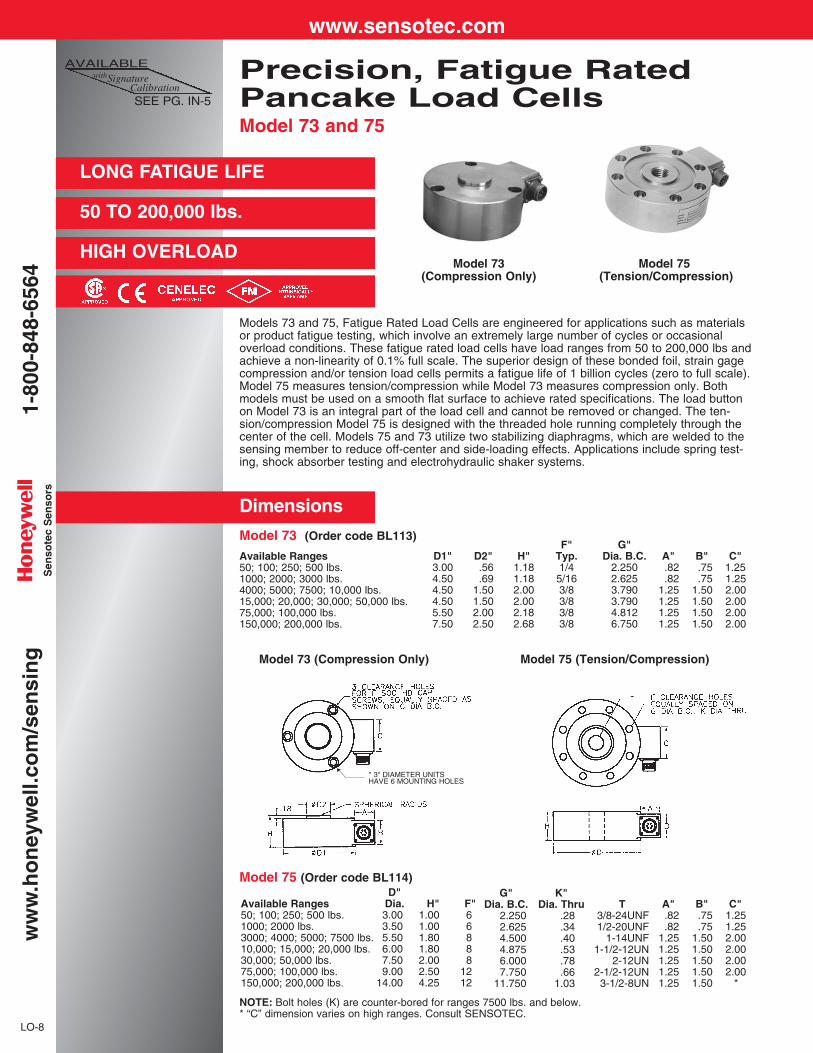
Precision, Fatigue RatedPancake Load CellsModel 73 and 75
LO-8
Available Ranges50; 100; 250; 500 lbs.1000; 2000 lbs.3000; 4000; 5000; 7500 lbs.10,000; 15,000; 20,000 lbs.30,000; 50,000 lbs.75,000; 100,000 lbs.150,000; 200,000 lbs.
G"Dia. B.C.
2.2502.6254.5004.8756.0007.750
11.750
K"Dia. Thru
.28
.34
.40
.53
.78
.661.03
A".82.82
1.251.251.251.251.25
B".75.75
1.501.501.501.501.50
C"1.251.252.002.002.002.00
*
T3/8-24UNF1/2-20UNF
1-14UNF1-1/2-12UN
2-12UN2-1/2-12UN
3-1/2-8UN
D"Dia.3.003.505.506.007.509.00
14.00
H"1.001.001.801.802.002.504.25
F"66888
1212
NOTE: Bolt holes (K) are counter-bored for ranges 7500 lbs. and below.* “C” dimension varies on high ranges. Consult SENSOTEC.
LONG FATIGUE LIFE
50 TO 200,000 lbs.
HIGH OVERLOAD
Models 73 and 75, Fatigue Rated Load Cells are engineered for applications such as materialsor product fatigue testing, which involve an extremely large number of cycles or occasionaloverload conditions. These fatigue rated load cells have load ranges from 50 to 200,000 lbs andachieve a non-linearity of 0.1% full scale. The superior design of these bonded foil, strain gagecompression and/or tension load cells permits a fatigue life of 1 billion cycles (zero to full scale).Model 75 measures tension/compression while Model 73 measures compression only. Bothmodels must be used on a smooth flat surface to achieve rated specifications. The load buttonon Model 73 is an integral part of the load cell and cannot be removed or changed. The ten-sion/compression Model 75 is designed with the threaded hole running completely through thecenter of the cell. Models 75 and 73 utilize two stabilizing diaphragms, which are welded to thesensing member to reduce off-center and side-loading effects. Applications include spring test-ing, shock absorber testing and electrohydraulic shaker systems.
Available Ranges50; 100; 250; 500 lbs.1000; 2000; 3000 lbs.4000; 5000; 7500; 10,000 lbs.15,000; 20,000; 30,000; 50,000 lbs.75,000; 100,000 lbs.150,000; 200,000 lbs.
F"Typ.1/45/163/83/83/83/8
G"Dia. B.C.
2.2502.6253.7903.7904.8126.750
A".82.82
1.251.251.251.25
B".75.75
1.501.501.501.50
C"1.251.252.002.002.002.00
D1"3.004.504.504.505.507.50
D2".56.69
1.501.502.002.50
H"1.181.182.002.002.182.68
Model 75 (Order code BL114)
Model 73 (Order code BL113)
Dimensions
AVAILABLEwithSignature
CalibrationSEE PG. IN-5
Model 73 Model 75 (Compression Only) (Tension/Compression)
Model 73 (Compression Only) Model 75 (Tension/Compression)
* 3" DIAMETER UNITSHAVE 6 MOUNTING HOLES
www.sensotec.com1-
800-
848-
6564
ww
w.h
on
eyw
ell.c
om
/sen
sin
gS
enso
tec
Sen
sors

General Information
LO-9
LO
AD
FA
TIG
UE
RA
TE
D
Options (See Appendix)Temperature compensated 1b, 1c, 1d, 1e, 1f; Int. shunt cal 8a (≥1000 lbs. only); Special calibration 30a, 30b(Model 75 only); Signature calibration 53e
Premium Options: 1i; 2N; 2q; 3a; 6e; 6f; 6g; 6h; 6i; 6j; Int. amps 2a (Model 73), 2b (Model 75), 2j; Intrinsically safe amp 2n.
Accessories: Mating connectors and connector/cable assemblies; Pull plates; Load buttons
How to order (See Pg. AP-19)Load cell selection flow chart (See Pg. LO-1)
NOTES: *Standard calibration for tension/compression load cells is in tension only.Internal amplifiers are available for all ranges. Internal amplification for ranges <3000 lbs. (“H” dimension <1.80") may increase height.
Model 73 Model 75(Compression only) (Tension/Compression)Order Code BL113 Order code BL114
50 to 200,000 lbs. 50 to 200,000 lbs.±0.1% F.S. ±0.1% F.S.±0.1% F.S. ±0.1% F.S.
±0.03% F.S. ±0.03% F.S.2mV/V 2mV/VInfinite Infinite1 billion 1 billion
-65° F to 250° F -65° F to 250° F60° F to 160° F 60° F to 160° F
.002% F.S./° F .002% F.S./° F.002% Rdg./° F .002% Rdg./° F
Bonded Foil Bonded foil10VDC 10VDC
350 ohms 350 ohms#2 (See Pg. AP-8) #2 (See Pg. AP-8)
PTIH-10-6P or equiv. PTIH-10-6P or equiv.(Hermetic stainless) (Hermetic stainless)
MS3102E-14S-6P or equiv. MS3102E-14S-6P or equiv.
PT06A-10-6S or equiv. PT06A-10-6S or equiv.MS3106A-14S-6S or equiv. MS3106A-14S-6S or equiv.
200% of capacity 200% of capacityN/A See table
Stainless Steel Stainless SteelStainless Steel Carbon Steel
.0022" .0035"
.0022" .0035"
±5VDC, 4-20mA 0-5VDC, 4-20mA
Load Ranges...............................Non-Linearity (max) ....................Hysteresis (max) .........................Non-repeatability( max)...............Output (standard) ........................Resolution ...................................Life cycle .....................................
Temperature, Operating..............Temperature, Compensated .......Temperature Effect
- Zero (max) ............................- Span (max) ...........................
Strain Gage Type........................Excitation (calibration).................Bridge Resistance.......................Wiring Code (std) ........................Electrical Termination (std)
50 to 2000 lbs .........................
3000 to 200,000 lbs ................Mating Connector (not incl.)
50 to 2000 lbs .........................3000 to 200,000 lbs ................
Static Overload Capacity ............Thread Size.................................Material
50 thru 100,000 lbs.125,00 thru 200,00 lbs ............
Deflection—Full Scale10-1000lbs ..............................≥1000 lbs ................................
Outputs Available........................
PERFORMANCE
ENVIRONMENTAL
ELECTRICAL
MECHANICAL
INTERNALLY AMPLIFIEDUNITS* (Optional)
ALLOWABLE EXTRANEOUS FORCE WITHOUT DAMAGE(% of load capacity)
Ranges Side Bending Torque TotalLoad (lb-in) (lb-in) Extraneous(lbs) Force
50; 100; 250; 500 lbs. 75% 60% 35% 100%
1000; 2000 lbs; 45% 35% 35% 100%
3000; 4000; 5000; 7500 30% 30% 25% 100%10,000; 15,000; 20,000 lbs.
30,000; 50,000; 75,000 30% 30% 15% 100%100,000; 150,000; 200,000 lbs.
1-800-848-6564
LO-12
LONG FATIGUE LIFE
250 TO 100,000 lbs.
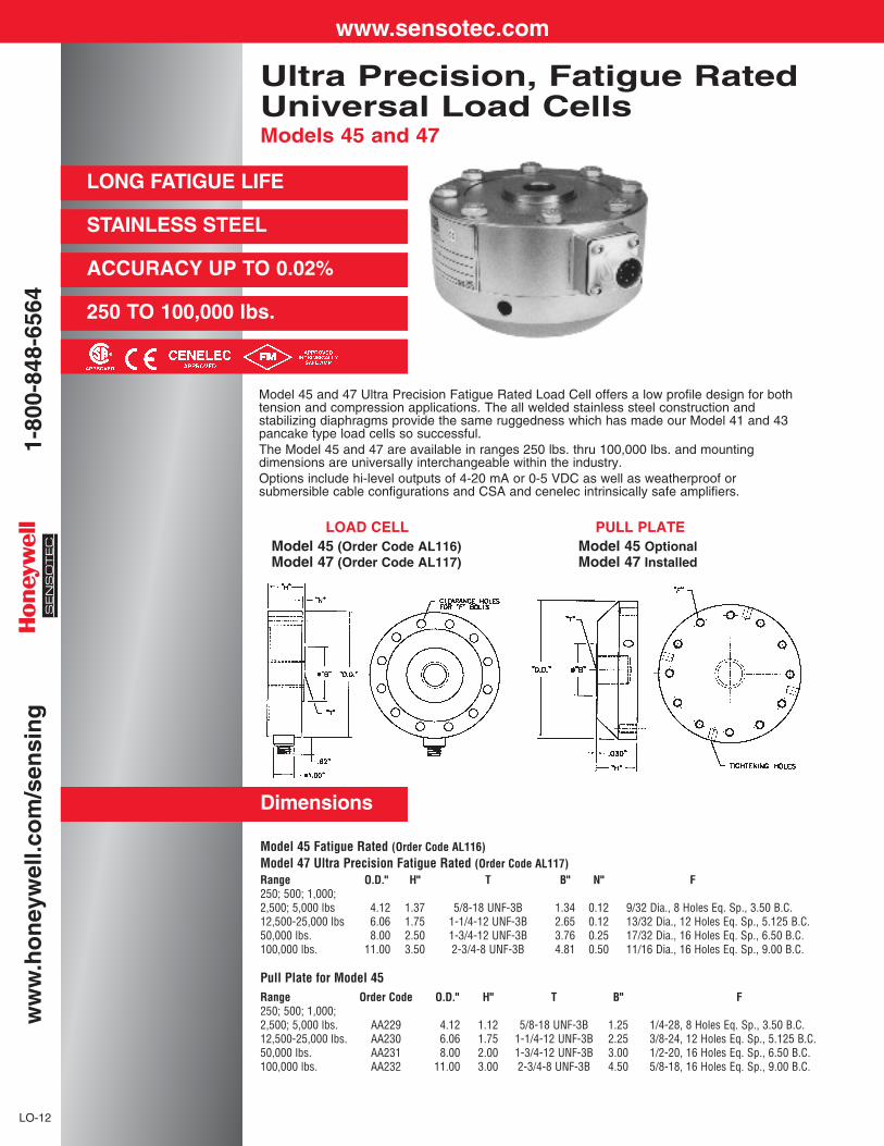
STAINLESS STEEL
ACCURACY UP TO 0.02%
Model 45 and 47 Ultra Precision Fatigue Rated Load Cell offers a low profile design for bothtension and compression applications. The all welded stainless steel construction and stabilizing diaphragms provide the same ruggedness which has made our Model 41 and 43pancake type load cells so successful.The Model 45 and 47 are available in ranges 250 lbs. thru 100,000 lbs. and mounting dimensions are universally interchangeable within the industry.Options include hi-level outputs of 4-20 mA or 0-5 VDC as well as weatherproof or submersible cable configurations and CSA and cenelec intrinsically safe amplifiers.
Ultra Precision, Fatigue RatedUniversal Load CellsModels 45 and 47
Dimensions
LOAD CELLModel 45 (Order Code AL116)Model 47 (Order Code AL117)
Model 45 Fatigue Rated (Order Code AL116)Model 47 Ultra Precision Fatigue Rated (Order Code AL117)Range O.D." H" T B" N" F250; 500; 1,000;2,500; 5,000 lbs 4.12 1.37 5/8-18 UNF-3B 1.34 0.12 9/32 Dia., 8 Holes Eq. Sp., 3.50 B.C.12,500-25,000 lbs 6.06 1.75 1-1/4-12 UNF-3B 2.65 0.12 13/32 Dia., 12 Holes Eq. Sp., 5.125 B.C.50,000 lbs. 8.00 2.50 1-3/4-12 UNF-3B 3.76 0.25 17/32 Dia., 16 Holes Eq. Sp., 6.50 B.C.100,000 lbs. 11.00 3.50 2-3/4-8 UNF-3B 4.81 0.50 11/16 Dia., 16 Holes Eq. Sp., 9.00 B.C.
Pull Plate for Model 45Range Order Code O.D." H" T B" F250; 500; 1,000;2,500; 5,000 lbs. AA229 4.12 1.12 5/8-18 UNF-3B 1.25 1/4-28, 8 Holes Eq. Sp., 3.50 B.C.12,500-25,000 lbs. AA230 6.06 1.75 1-1/4-12 UNF-3B 2.25 3/8-24, 12 Holes Eq. Sp., 5.125 B.C.50,000 lbs. AA231 8.00 2.00 1-3/4-12 UNF-3B 3.00 1/2-20, 16 Holes Eq. Sp., 6.50 B.C.100,000 lbs. AA232 11.00 3.00 2-3/4-8 UNF-3B 4.50 5/8-18, 16 Holes Eq. Sp., 9.00 B.C.
PULL PLATEModel 45 OptionalModel 47 Installed
www.sensotec.com1-
800-
848-
6564
ww
w.h
on
eyw
ell.c
om
/sen
sin
g
PERFORMANCE
ENVIRONMENTAL
ELECTRICAL
MECHANICAL
LO-13
LO
AD
PR
EC
ISIO
N F
AT
IGU
E R
AT
ED
How to order (See Pg. AP-19)
Load cell selection flow chart (See Pg. LO-1)
Model 45 (Fatigue Rated) is standard without a pull plate. On Ultra Precision Model 47, the load cell and pullplate are calibrated as a unit. Internal amplifiers are available for all ranges. Internal amplification for ranges<12,500 lbs. (“H” dimension <1.80") may increase height. Using an in-line amplifier for ranges <12,500 lbs. willavoid this height increase.
Options: A.S.T.M. E74 calibration; Overload stops, compression only, engage at approximately 125% of cellcapacity—requires pull plate. Internal amplifiers; 2a; 2b; 2c; 2j; 2q. Note: Some specs may vary with amplifieroptions, consult Sensotec for details.
Premium Options: Signature calibration 53e (Model 45 only) Intrinsically safe amp CENELEC Approved 2n.
Accessories: Mating connectors and connector/cable assemblies; Load Buttons (See Appendix).
Range...................................................... 250*; 500; 2,500; 12,500; 50,000 lb. 100,000 lb................................................................. 1,000 lb. 5,000 lb. 25,000 lb.
Output, standard (mV/V) ......................... 2.0 2.0 2.0 2.0 2.0Static error band, (+/-%F.S.)1 .................. 0.04 (0.02) 0.05 (0.03) 0.05 (0.04) 0.05 (0.04) 0.06 (0.05)Nonlinearity, (+/-%F.S.)2.......................... 0.05 (0.02) 0.05 (0.03) 0.05 (0.04) 0.05 (0.04) 0.05 (0.05)Hysteresis, (+/-%F.S.)2 ............................ 0.02 (0.02) 0.03 (0.03) 0.03 (0.03) 0.03 (0.03) 0.04 (0.03)Non-Repeatability, (+/-%F.S.)2 ................ 0.02 (0.01) 0.02 (0.01) 0.02 (0.01) 0.02 (0.01) 0.02 (0.01)Fatigue Life Cycle ................................... 108 fully reversed
Temperature, Operating.......................... -65°F to 200°FTemperature, Compensated ................... 0°F to 150°FTemperature Effect
– Zero (max) %F.S./°F........................ 0.0008– Span (max) %Rdg./°F...................... 0.0008
Excitation, calibrated (VDC).................... 10Excitation, maximum (VDC).................... 20Bridge Resistance, nominal Ω ............... 350Insulation Resistance mΩ ....................... 5000 @ 50 VDCWiring Code, standard ............................ #39, see appendixElectrical Termination.............................. PC02A-10-6PMating Harness ....................................... AA163
Deflection @ full scale load (IN) ............. 0.0015 0.001 0.002 0.002 0.0025Static Overload Capacity, (+/-%F.S.)***.. 300 300 300 300 300Ringing Frequency (kHz) ........................ 2.4, 2.4, 3.4 6.8, 9.1 5.7, 7.0 6.3 4.5Weight, Element (lb) ............................... 3.1 3.2 8.8 22 55Base (optional on model 45) ................... AA229 AA229 AA230 AA231 AA232Weight, base (lb) ..................................... 3.5 3.5 11 20 61Load Button (optional)............................. AA290 AA290 AA291 AA292 AA293
General Information (See Appendix)
Model 45 (Model 47)**
* 250 lb range has 700 Ohm bridge resistance** Data for model 47 shown in parenthesis, otherwise same for both models***Off-axis loading maximum allowable 50% of F.S.
1 Static error band is the guaranteed performance specification. The static error band is calculated as the bestfit straight line through zero, including the effects of non-linearity, hysteresis and non-repeatability.
2 Values noted are typical values but fall within the static error band.
Fatigue Rated (Fatigue Rated Ultra-Precision)
1-800-848-6564
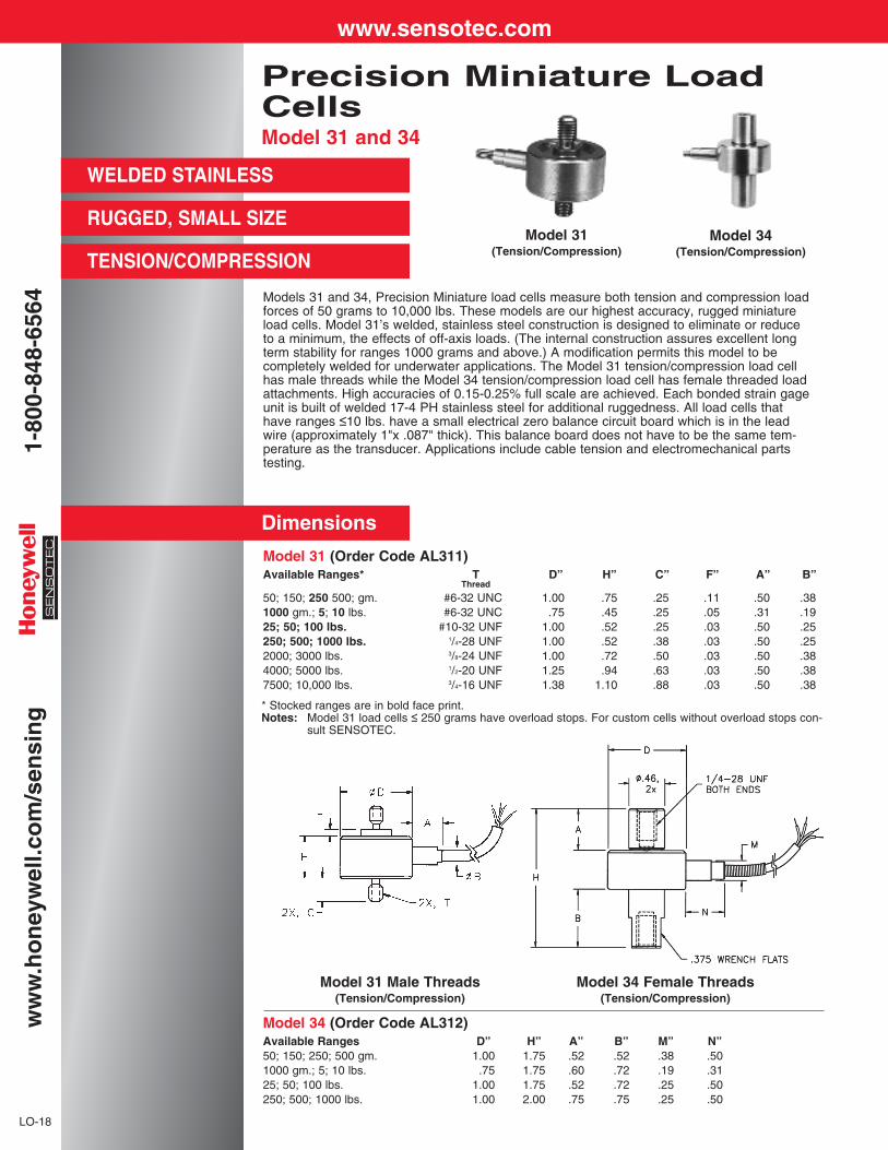
Models 31 and 34, Precision Miniature load cells measure both tension and compression loadforces of 50 grams to 10,000 lbs. These models are our highest accuracy, rugged miniatureload cells. Model 31’s welded, stainless steel construction is designed to eliminate or reduceto a minimum, the effects of off-axis loads. (The internal construction assures excellent longterm stability for ranges 1000 grams and above.) A modification permits this model to becompletely welded for underwater applications. The Model 31 tension/compression load cellhas male threads while the Model 34 tension/compression load cell has female threaded loadattachments. High accuracies of 0.15-0.25% full scale are achieved. Each bonded strain gageunit is built of welded 17-4 PH stainless steel for additional ruggedness. All load cells thathave ranges ≤10 lbs. have a small electrical zero balance circuit board which is in the leadwire (approximately 1"x .087" thick). This balance board does not have to be the same tem-perature as the transducer. Applications include cable tension and electromechanical partstesting.
Precision Miniature LoadCellsModel 31 and 34
WELDED STAINLESS
LO-18
Dimensions
* Stocked ranges are in bold face print.Notes: Model 31 load cells ≤ 250 grams have overload stops. For custom cells without overload stops con-
sult SENSOTEC.
RUGGED, SMALL SIZE
TENSION/COMPRESSION
Model 34 (Order Code AL312)Available Ranges D” H” A” B” M” N”50; 150; 250; 500 gm. 1.00 1.75 .52 .52 .38 .501000 gm.; 5; 10 lbs. .75 1.75 .60 .72 .19 .3125; 50; 100 lbs. 1.00 1.75 .52 .72 .25 .50250; 500; 1000 lbs. 1.00 2.00 .75 .75 .25 .50
Model 31 (Order Code AL311)Available Ranges* T D” H” C” F” A” B”
Thread
50; 150; 250 500; gm. #6-32 UNC 1.00 .75 .25 .11 .50 .381000 gm.; 5; 10 lbs. #6-32 UNC .75 .45 .25 .05 .31 .1925; 50; 100 lbs. #10-32 UNF 1.00 .52 .25 .03 .50 .25250; 500; 1000 lbs. 1/4-28 UNF 1.00 .52 .38 .03 .50 .252000; 3000 lbs. 3/8-24 UNF 1.00 .72 .50 .03 .50 .384000; 5000 lbs. 1/2-20 UNF 1.25 .94 .63 .03 .50 .387500; 10,000 lbs. 3/4-16 UNF 1.38 1.10 .88 .03 .50 .38
Model 34(Tension/Compression)
Model 34 Female Threads(Tension/Compression)
Model 31 Male Threads(Tension/Compression)
Model 31(Tension/Compression)
www.sensotec.com1-
800-
848-
6564
ww
w.h
on
eyw
ell.c
om
/sen
sin
g
General Information
LO-19
LO
AD
MIN
IAT
UR
E
Options (See Appendix)Temperature compensated 1b, 1c, 1f; Special calibration 30a, 30b
Premium Options: 1d, 1e, 1g, 1h (≥25 lb), 1i; 6d; 9a (≥ 5 lb.)
Accessories: Rod end attachments for Model 31
How to order (See Pg. AP-19)Load cell selection flow chart (See Pg. LO-1)Installation Note: Maximum torque for installation of Model 31 in ranges less than 25 lbs. is 12 inch lbs.
Load Ranges ................................Non-Linearity/Hysteresis (max)
50 gms to 1000 gms ................5 to 250 lbs...............................500 to 10,000 lbs......................
Non-Repeatability (max)50 gms to 1000 gms ................5 to 10,000 lbs..........................
Output (standard)50 to 150 gms (semi) ...............250 to 500 gms (semi) .............1000 gms..................................5 lbs. to 10,000 lbs. (foil)..........
Resolution ....................................
Temperature, Operating ...............Temperature, Compensated ........Temperature Effect
– Zero/Span (max)50 gms to 500 gms ..................1000 gms..................................5 to 10,000 lbs..........................
Strain Gage Type .........................Excitation (Calibration)
50 gms to 10 lbs.......................20 lbs. to 10,000 lbs. ................
Insulation Resistance ...................Bridge Resistance
50 gms to 500 gms ..................1000 gms..................................5 to 10,000 lbs..........................
Shunt Calibration Data .................Wiring Code (std) .........................Electrical Termination (std)...........
Overload, Safe .............................Thread Size ..................................Deflection – Full Scale .................Casing material ............................Weight (nom)................................
Outputs Available .........................
Model 31(Male Threads)
(Tension/Compression)Order Code AL311
50 gms to 10,000 lbs.
±0.15% F.S.±0.15% F.S.±0.2% F.S.
±0.1% F.S.±0.05% F.S.
.1mV/V/gm max20mV/V
1.5mV/V (nominal)2mV/VInfinite
-65° F to 250° F60° F to 160° F
.015% F.S./ ° F
.005% F.S./ ° F
.005% F.S./ ° F
Foil or Semiconductor
5.00VDC10.0VDC
5000 megohm @ 50VDC
500 ohm (semi)350 ohm (foil)350 ohm (foil)
Included#1 (See Pg. AP-8)Teflon cable (5 ft.)
50% over capacitySee table
.0005"-.0020"17-4 PH Stainless
1.6 oz.
±5VDC, 4-20mA
Model 34(Female Threads)
(Tension/Compression)Order Code AL312
50 gms to 1,000 lbs.
±0.15% F.S.±0.15% F.S.±0.2% F.S.
±0.1% F.S.±0.05% F.S.
.1mV/V/gm20mV/V
1.5mV/V (nom)2mV/VInfinite
-65° F to 250° F60° F to 160° F
.015% F.S./ ° F
.005% F.S./ ° F
.005% F.S./ ° F
Foil or Semiconductor
5.00VDC10.0VDC
5000 megohm @ 50VDC
500 ohm (semi)350 ohm (foil)350 ohm (foil)
Included#1 (See Pg. AP-8)Teflon cable (5 ft.)
50% over capacitySee table
.0005"-.0020"17-4 PH Stainless
2.5 oz.
±5VDC, 4-20mA
PERFORMANCE
ENVIRONMENTAL
ELECTRICAL
MECHANICAL
IN-LINE AMPLIFIERS(Optional)
NOTES *Standard calibration for tension/compression load cells is in tension only.
1-800-848-6564
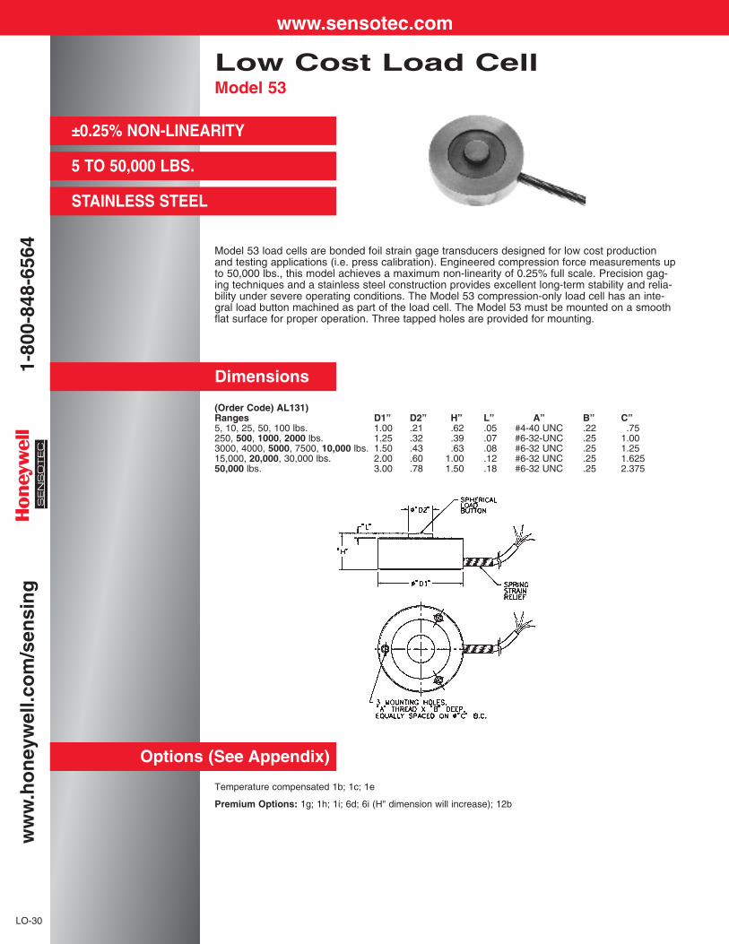
Model 53 load cells are bonded foil strain gage transducers designed for low cost productionand testing applications (i.e. press calibration). Engineered compression force measurements upto 50,000 lbs., this model achieves a maximum non-linearity of 0.25% full scale. Precision gag-ing techniques and a stainless steel construction provides excellent long-term stability and relia-bility under severe operating conditions. The Model 53 compression-only load cell has an inte-gral load button machined as part of the load cell. The Model 53 must be mounted on a smoothflat surface for proper operation. Three tapped holes are provided for mounting.
Low Cost Load CellModel 53
±0.25% NON-LINEARITY
5 TO 50,000 LBS.
STAINLESS STEEL
LO-30
Dimensions
Options (See Appendix)
Temperature compensated 1b; 1c; 1e
Premium Options: 1g; 1h; 1i; 6d; 6i (H" dimension will increase); 12b
(Order Code) AL131)Ranges D1” D2” H” L” A” B” C”5, 10, 25, 50, 100 lbs. 1.00 .21 .62 .05 #4-40 UNC .22 .75250, 500, 1000, 2000 lbs. 1.25 .32 .39 .07 #6-32-UNC .25 1.003000, 4000, 5000, 7500, 10,000 lbs. 1.50 .43 .63 .08 #6-32 UNC .25 1.2515,000, 20,000, 30,000 lbs. 2.00 .60 1.00 .12 #6-32 UNC .25 1.62550,000 lbs. 3.00 .78 1.50 .18 #6-32 UNC .25 2.375
www.sensotec.com1-
800-
848-
6564
ww
w.h
on
eyw
ell.c
om
/sen
sin
g
LO
AD
LO
W C
OS
T C
OM
PR
ES
SIO
N
LO-31
Model 53(Compression Only)Order Code AL131)
PERFORMANCE Load Ranges . . . . . . . . . . . . . . . 5 to 50,000 lbs.Non-Linearity (max) . . . . . . . . . . ±0.25% F.S.Hysteresis (max) . . . . . . . . . . . . ±0.3% F.S.Non-Repeatability (max) . . . . . . . ±0.1% F.S.Output (standard) . . . . . . . . . . . . 2mV/VResolution . . . . . . . . . . . . . . . . . Infinite
ENVIRONMENTAL Temperature, Operating . . . . . . . -65° F to 250° FTemperature, Compensated . . . . 60° F to 160° FTemperature Effect
– Zero (max) . . . . . . . . . . . . . .005% F.S./° F– Span (max) . . . . . . . . . . . . . .01% Rdg./° F
ELECTRICAL Strain Gage Type . . . . . . . . . . . . Bonded foilExcitation (calibration) . . . . . . . . 10VDCExcitation (acceptable) . . . . . . . . Up to 10VDC or ACInsulation Resistance . . . . . . . . . 5000 megohm @ 50VDCBridge Resistance . . . . . . . . . . . 350 ohmsShunt Calibration Data . . . . . . . . IncludedWiring Code (std.) . . . . . . . . . . . #1 (See Pg. AP-8)Electrical Termination (std) . . . . . Teflon cable (5 ft.)
MECHANICAL Overload, Safe . . . . . . . . . . . . . . 50% over capacityDeflection – Full Scale . . . . . . . . .001" – .003"Casing Material . . . . . . . . . . . . . 17-4 PH Stainless
IN-LINE AMPLIFIERS Outputs Available . . . . . . . . . . . . 0-5VDC, 4-20mA(Optional)
How to order (See Pg. AP-19)Load cell selection flow chart (See Pg. LO-1)
General Information
1-800-848-6564
Model 31(Male Threads)
(Tension/Compression)Order Code AL311
150 gms to 1000 lbs.±0.5% F.S.±0.1% F.S.
15mV/V nom.1.5mV/V nom.2mV/V nom.
Infinite
-65° F to 250° F60° F to 160° F
0.01% F.S./ ° F0.02% Rdg./ ° F
Foil or Semi-Cond.
5VDC5000 megohm @ 50VDC
500 ohm (semi)350 ohm (foil)
Included#1 (See Pg. AP-6)Cable exit (5 ft.)
LO-20
Temperature compensated 1b, 1c
Premium Options: 1e (>1000 gms only), 1f (>1000 gms only)
Load Ranges ................................Non-Linearity/Hysteresis (max) ....Non-Repeatability (max)...............Output (standard)
150 to 500 gms ........................1000 gms..................................5 lbs. to 1,000 lbs. ....................
Resolution ....................................
Temperature, Operating ...............Temperature, Compensated ........Temperature Effect
– Zero (max).............................– Span (max)............................
Strain Gage Type .........................Excitation (calibration)
50 gms to 1000 lbs...................Insulation Resistance ...................Bridge Resistance
50 gms to 500 gms ..................1000 gms to 1000 lbs...............
Shunt Calibration Data .................Wiring Code (std) .........................Electrical Termination (std)...........
PERFORMANCE
ENVIRONMENTAL
ELECTRICAL
MECHANICAL
150 gms to 1000 lbs.
STAINLESS STEEL
Options (See Appendix)
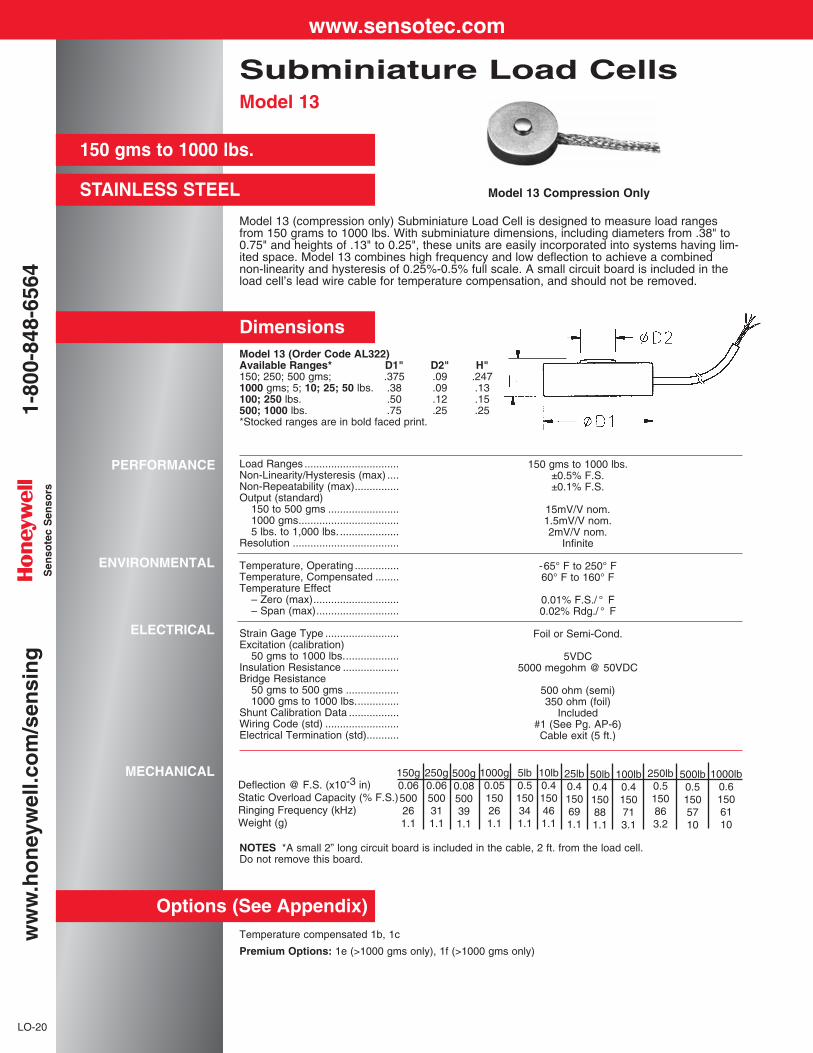
Model 13 (compression only) Subminiature Load Cell is designed to measure load rangesfrom 150 grams to 1000 lbs. With subminiature dimensions, including diameters from .38" to0.75" and heights of .13" to 0.25", these units are easily incorporated into systems having lim-ited space. Model 13 combines high frequency and low deflection to achieve a combinednon-linearity and hysteresis of 0.25%-0.5% full scale. A small circuit board is included in theload cell’s lead wire cable for temperature compensation, and should not be removed.
NOTES *A small 2” long circuit board is included in the cable, 2 ft. from the load cell.Do not remove this board.
Dimensions
Subminiature Load CellsModel 13
Model 13 (Order Code AL322)Available Ranges* D1" D2" H"150; 250; 500 gms; .375 .09 .2471000 gms; 5; 10; 25; 50 lbs. .38 .09 .13100; 250 lbs. .50 .12 .15500; 1000 lbs. .75 .25 .25*Stocked ranges are in bold faced print.
Model 13 Compression Only
Deflection @ F.S. (x10-3 in)Static Overload Capacity (% F.S.)Ringing Frequency (kHz)Weight (g)
150g0.06500261.1
250g0.06500311.1
500g0.08500391.1
1000g0.05150261.1
5lb0.5150341.1
10lb0.4150461.1
25lb0.4150691.1
50lb0.4150881.1
100lb0.4150713.1
250lb0.5150863.2
500lb0.51505710
1000lb0.61506110
www.sensotec.com1-
800-
848-
6564
ww
w.h
on
eyw
ell.c
om
/sen
sin
gS
enso
tec
Sen
sors
LO
AD
SU
BM
INIA
TU
RE
LO-21
Options (See Appendix)
Load Ranges ................................Non-Linearity (max)..................Hysteresis (max) ......................
Non-Repeatability (max)...............Output (standard)
150 gms to 500 gms ................1000 gms to 1000 lbs...............
Resolution ....................................Zero Balance (nom.) ....................
Temperature, Operating ...............Temperature, Compensated ........Temperature Effect
– Zero (max).............................– Span (max)............................
Strain Gage Type150 gms to 500 gms ..................1000 gms to 10,000 lbs .............
Excitation (calibration) ..................Insulation Resistance ...................Bridge Resistance
150 gms to 500 gms ................1000 gms to 10,000 lbs............
Wiring Code (std) .........................Electrical Termination (std)...........
Model 31(Male Threads)
(Tension/Compression)Order Code AL311
150 gms to 1000 lbs.±0.5% F.S.±0.5% F.S.±0.1% F.S.
10mV/V nom.2mV/V nom.
Infinite± 3% F.S.
-65° F to 250° F60° F to 160° F
0.01% F.S./ ° F0.02% Rdg./ ° F
SemiconductorFoil
5VDC5000 megohm @ 50VDC
500 ohm (semi)350 ohm (foil)
#1 (See Appendix)5’ integral cable with balance board*
NOTE: Standard calibration for tension/compression load cells is in tension only.* A small 2” long circuit board is included in the cable, 2 ft. from the load cell. Do not remove this board.
Model 11 (Order Code BL321)Available Ranges øD” T H” A” B” Q *150; 250; 500; 1000 gms .50 #4-40UNC .29 .19 .18 45; 10; 25; 50; 100 lbs. .50 #4-40UNC .29 .19 .18 4250; 500; 1000 lbs. .75 1/4-28UNF .38 .31 .31 20
* “Q” = maximum tightening torque allowed inch-lbs.
150 gms to 1000 lbs.
STAINLESS STEEL
Subminiature Load CellsModel 11
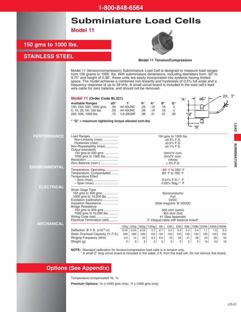
Model 11 (tension/compression) Subminiature Load Cell is designed to measure load rangesfrom 150 grams to 1000 lbs. With subminiature dimensions, including diameters from .50" to0.75" and height of 0.38", these units are easily incorporated into systems having limitedspace. The model achieves a combined non-linearity and hysteresis of 0.5% full scale and afrequency response of up to 58 kHz. A small circuit board is included in the load cell’s leadwire cable for zero balance, and should not be removed.
Model 11 Tension/Compression
Temperature compensated 1b, 1c
Premium Options: 1e (>1000 gms only), 1f (>1000 gms only)
PERFORMANCE
ENVIRONMENTAL
ELECTRICAL
MECHANICAL150g 250g 500g 1000g 5lb 10lb 25lb 50lb 100lb 250lb 500lb 1000lb
Deflection @ F.S. (x10-3 in) 0.05 0.04 0.03 0.7 0.7 0.5 0.4 0.4 0.4 1.1 1.5 2.0Static Overload Capacity (% F.S.) 500 500 500 150 150 150 150 150 150 150 150 150Ringing Frequency (kHz) 9.5 14 22 6.5 9.8 16 29 41 58 23 28 34Weight (g) 5 5 5 5 5 5 5 5 5 19 19 19
“A”
“B”
1-800-848-6564

Model LFH-7I Subminiature Load Cell is a low profile force transducer for applications withminimal space and high capacity requirements. This transducer utilizes foil strain gages tomeasure compression loads of up to 10,000 lbs. and achieves non-linearity and hysteresis of+/- 0.5% full scale. The top of the load cell is the area where the force is applied and the basering of the load cell must be placed on a hard, machine-ground flat surface to obtain optimumaccuracy.
Subminiature Load CellsModel LFH-7I (Top Hat)
250-10,000 LBS
LO-22
Dimensions
Options (See Appendix)
STAINLESS STEEL
Load Ranges ................................Overall Accuracy ..........................Output...........................................Temperature, Operating ...............Temperature, Compensated ........Temperature Effect
– Zero (max).............................– Span (max)............................
Excitation (calibrated)...................Bridge Resistance ........................Wiring Code (std) .........................Electrical
Termination (std) ......................Overload, Safe .............................Deflection—Full Scale ..................
Model LFH-7I(Compression Only)Order Code BL351
250 to 10,000 lbs.±0.7% F.S.
1.5mV/V-2.5mV/V-65° F to 250° F60° F to 160° F
.01% F.S./ ° F.01% Rdg./ ° F
5VDC350 ohms
#1 (See Pg. AP-8)
Cable (5 ft.)50% over capacity
.001"-.003"
Top Hat Model LFH-7I (Order Code BL351)D1” D2”
Available Ranges Dia. Dia. H” F”250 lbs. .50 (1.27 cm) .22 (.69 cm) .38 (.97 cm) .13 (.33 cm)500 lbs. .50 (1.27 cm) .28 (.71 cm) .38 (.97 cm) .13 (.33 cm)1000 lbs. .50 (1.27 cm) .31 (.79 cm) .38 (.97 cm) .13 (.33 cm)2000 lbs. .50 (1.27 cm) .41 (1.04 cm) .38 (.97 cm) .13 (.33 cm)3000 lbs. .50 (1.27 cm) .45 (1.14 cm) .38 (.97 cm) .13 (.33 cm)4000 lbs. .63 (1.60 cm) .49 (1.24 cm) .60 (1.52 cm) .23 (.58 cm)5000 lbs. .63 (1.60 cm) .53 (1.35 cm) .60 (1.52 cm) .23 (.58 cm)7500 lbs. .88 (2.24 cm) .63 (1.60 cm) .63 (1.60 cm) .54 (1.37 cm)10,000 lbs. .88 (2.24 cm) .63 (1.60 cm) .63 (1.60 cm) .54 (1.37 cm)
SPECIFICATIONS
Temperature compensated 1b, 1f
* Bridge resistance is 700 ohms on ranges > 5000 lbs.
250 lbs TO 5000 lbs 7500 lbs TO 10,00 lbs
0.18”
0.32”
Ø 0.14”Ø 0.22”
Ø 0.25”
Model LFH-7ICompression Only
www.sensotec.com1-
800-
848-
6564
ww
w.h
on
eyw
ell.c
om
/sen
sin
gS
enso
tec
Sen
sors

Model UG Ultra Precision Universal load cell achieves scale quality and performance standards.The Model UG achieves ±0.03% non-linearity with very little deflection (typically .0045"). It uti-lizes a four arm strain gage bridge which is bonded and tested for high precision and depend-ability. Female threads on both ends facilitate mounting in any position for tension, compression,or universal force measurements. Model UG load cells can be used in both static and dynamicapplications. Stainless steel construction ensures high reliability. Typical applications includewind tunnels; rocket engine tests; hopper, tank, or bin weighing; and weighing scales.
Ultra Precision Universal Canister Load CellsModel UG
0.03% NON-LINEARITY
LO-14
Dimensions
Options (See Appendix)
Available Ranges100; 250; 500 lbs.1000; 2000; 3000; 4000 lbs.5000; 7500; 10,000 lbs.15,000; 20,000; 30,000 lbs.50,000; 75,000 lbs.100,000; 150,000 lbs.200,000 lbs.
TTyp.
3/8-24 UNF x 7/161/2-20 UNF x 5/81-14 UN x 1-1/8
1-1/2-12 UNF x 22-12 UN x 2-1/23-8 UN x 4-1/24-8 UN x 5-1/2
A".09.09.19.63.69.69.75
H"2.754.135.888.50
12.0017.0021.00
D1"Dia.2.002.503.505.006.008.009.00
D2"Dia..63.75
1.562.383.636.007.50
100-200,000 lbs.
STAINLESS STEEL
Model UG(Order Code BL122)
PERFORMANCE
ENVIRONMENTAL
ELECTRICAL
MECHANICAL
Model UGOrder Code BL122
Load Ranges ................................ 100 to 200,000 lbs.Non-Linearity (max)...................... ±0.03% F.S.*Hysteresis (max) .......................... ±0.03% F.S.Non-Repeatability (max)............... ±0.02% F.S.Output........................................... 3mV/VResolution .................................... InfiniteCreep (max) ................................. .02% (20 min.)
Temperature, Operating ............... -30° F to 185° FTemperature, Compensated ........ 60° F to 160° FTemperature Effect
- Zero (max) ............................. .0015% F.S./° F- Span (max) ............................ .0008% Rdg./° F
Strain Gage Type ......................... Bonded foilExcitation (calibration) .................. 10VDCBridge Resistance ........................ 350 ohmsWiring Code (std) ......................... #2 (See Pg. AP-8)Electrical Termination (std)
100-200,000 lbs........................ MS3102E-14S-6PMating Connector (not incl.) ......... MS3106A-14S-6S
Static Overload Capacity.............. 50% over capacityCasing Material ............................ Stainless steelDeflection—Full Scale .................. .0045"
Temperature compensated 1b, 1c; Electrical termination 6e, 6f, 6g, 6j; Int. Shunt cal 8a Special calibration 30a, 30b; Signature calibration 53e
Premium Options: 9a, 9b
Accessories: Mating connectors and connector/cable assemblies; Load buttons
AVAILABLEwithSignature
CalibrationSEE PG. IN-5
Notes Standard calibration for tension/compression load cells is in tension only.* 0.05% at ranges ≤ 250 lbs., and ≥ 75,000 lbs.
www.sensotec.com1-
800-
848-
6564
ww
w.h
on
eyw
ell.c
om
/sen
sin
g

LO
AD
UL
TR
A P
RE
CIS
ION
CO
MP
RE
SS
ION
LO-15
Temperature compensated 1b, 1c; Electrical termination 6a, 6e, 6f, 6g, 6h, 6i, 6j; Int. shunt cal 8a; Signature calibration 53e Premium Options: 9a, 9bAccessories: Mating connectors and connector/cable assemblies
0.03% LINEARITY & HYSTERESIS
10,000-500,000 lbs.
WELDED STAINLESS
Load Ranges ................................Linearity ........................................Hysteresis.....................................Non-Repeatability (max)...............Output...........................................Resolution ....................................Creep (max) .................................
Temperature, Operating ...............Temperature, Compensated ........Temperature Effect
– Zero (max).............................– Span (max)............................
Strain Gage Type .........................Excitation (calibration) ..................Bridge Resistance ........................Wiring Code (std) .........................Electrical Termination (std)...........Mating Connector (not incl.) .........
Static Overload Capacity..............Casing Material ............................Deflection—Full Scale ..................*0.05% at ranges ≥ 75,000 lbs.
Model 415(0.1%)
Gage:Order Code AP411
Absolute:Order Code AP412
10,000 to 500,000 lbs.0.03%*0.03%*
±0.01% F.S.2mV/VInfinite
.03% (20 min.)
-30° to 185° F60° to 160° F
.0015% F.S./ ° F.0008% Rdg./ ° F
Bonded Foil10VDC
350 ohms#2 (See Pg. AP-6)MS3102E-14S-6PMS3106A-14S-6S
50% over capacityStainless steel
.0031"
PERFORMANCE
ENVIRONMENTAL
ELECTRICAL
MECHANICAL
Dimensions
Options (See Appendix)
Ultra Precision CompressionCanister Load CellModel WG
AVAILABLEwithSignature
CalibrationSEE PG. IN-5
Ranges D1” H” T” A” D2”10,000; 15,000; 25,000; 50,000 lbs. 2.88 (7.32 cm) 3.25 (8.26 cm) 1/2-20 UNF-2B .40 (1.02 cm) 1.25 (3.18 cm)100,000 lbs. 4.12 (10.46 cm) 5.00 (12.70 cm) 3/4-16 UNF-2B .51 (1.30 cm) 2.31 (5.87 cm)200,000; 300,000 lbs. 6.00 (15.24 cm) 7.25 (18.42 cm) 3/4-16 UNF-2B 1.04 (2.64 cm) 3.13 (7.95 cm)500,000 lbs. 6.50 (16.51 cm) 9.00 (22.86 cm) 3/4-16 UNF-2B .56 (1.42 cm) 3.69 (9.37 cm)
Model WG (Order Code BL125)
1-800-848-6564
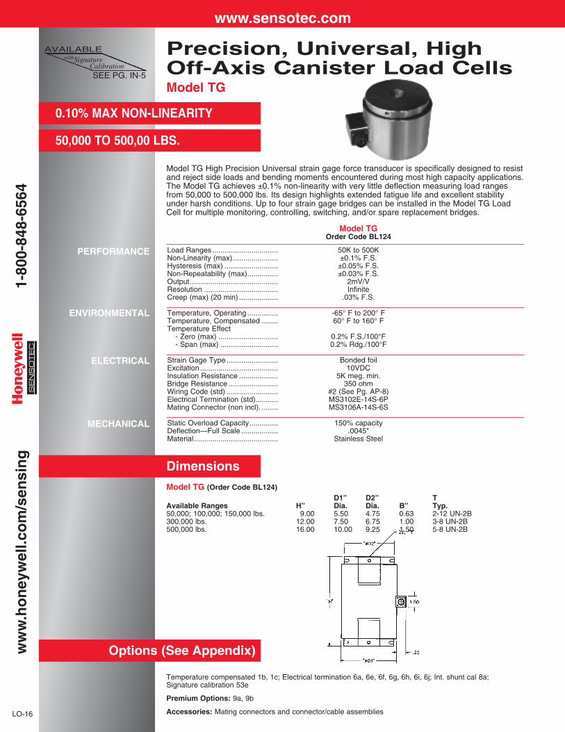
Model TG High Precision Universal strain gage force transducer is specifically designed to resistand reject side loads and bending moments encountered during most high capacity applications.The Model TG achieves ±0.1% non-linearity with very little deflection measuring load rangesfrom 50,000 to 500,000 lbs. Its design highlights extended fatigue life and excellent stabilityunder harsh conditions. Up to four strain gage bridges can be installed in the Model TG LoadCell for multiple monitoring, controlling, switching, and/or spare replacement bridges.
Precision, Universal, High Off-Axis Canister Load CellsModel TG
0.10% MAX NON-LINEARITY
50,000 TO 500,00 LBS.
LO-16
Dimensions
Options (See Appendix)
PERFORMANCE
ENVIRONMENTAL
ELECTRICAL
MECHANICAL
Temperature compensated 1b, 1c; Electrical termination 6a, 6e, 6f, 6g, 6h, 6i, 6j; Int. shunt cal 8a; Signature calibration 53e
Premium Options: 9a, 9b
Accessories: Mating connectors and connector/cable assemblies
Model TGOrder Code BL124
Load Ranges ................................ 50K to 500KNon-Linearity (max)...................... ±0.1% F.S.Hysteresis (max) .......................... ±0.05% F.S.Non-Repeatability (max)............... ±0.03% F.S.Output........................................... 2mV/VResolution .................................... InfiniteCreep (max) (20 min) ................... .03% F.S.
Temperature, Operating ............... -65° F to 200° FTemperature, Compensated ........ 60° F to 160° FTemperature Effect
- Zero (max) ............................. 0.2% F.S./100°F- Span (max) ............................ 0.2% Rdg./100°F
Strain Gage Type ......................... Bonded foilExcitation...................................... 10VDCInsulation Resistance ................... 5K meg. min.Bridge Resistance ........................ 350 ohmWiring Code (std) ......................... #2 (See Pg. AP-8)Electrical Termination (std)........... MS3102E-14S-6PMating Connector (non incl). ........ MS3106A-14S-6S
Static Overload Capacity.............. 150% capacityDeflection—Full Scale .................. .0045"Material......................................... Stainless Steel
Model TG (Order Code BL124)D1” D2” T
Available Ranges H” Dia. Dia. B” Typ.50,000; 100,000; 150,000 lbs. 9.00 5.50 4.75 0.63 2-12 UN-2B300,000 lbs. 12.00 7.50 6.75 1.00 3-8 UN-2B500,000 lbs. 16.00 10.00 9.25 1.50 5-8 UN-2B
AVAILABLEwithSignature
CalibrationSEE PG. IN-5
www.sensotec.com1-
800-
848-
6564
ww
w.h
on
eyw
ell.c
om
/sen
sin
g
UP TO 3 MILLION POUNDS
HERMETIC
AMPLIFIED OUTPUT AVAILABLE
STAINLESS STEEL
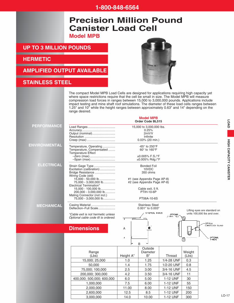
Precision Million PoundCanister Load CellModel MPB
LO
AD
HIG
H C
AP
AC
ITY
CA
NIS
TE
R
LO-17
The compact Model MPB Load Cells are designed for applications requiring high capacity yetwhere space restrictions require that the cell be small in size. The Model MPB will measurecompression load forces in ranges between 15,000 to 3,000,000 pounds. Applications includeimpact testing and mine shaft roof simulations. The diameter of these load cells ranges between1.25" and 10" while the height ranges between approximately 0.63" and 14" depending on therange desired.
Dimensions
PERFORMANCE
ENVIRONMENTAL
ELECTRICAL
MECHANICAL
Model MPBOrder Code BL515
Load Ranges ................................ 15,000 to 3,000,000 lbs.Accuracy....................................... 0.25%Output (nominal)........................... 2mV/VResolution .................................... InfiniteCreep (max) ................................. 0.03% (20 min.)
Temperature, Operating ............... -65° to 250°FTemperature, Compensated ........ 60° to 160°FTemperature Effect
–Zero (max).............................. ±0.005% F.S./°F–Span (max)............................. ±0.005% Rdg./°F
Strain Gage Type ......................... Bonded FoilExcitation (calibration) .................. 10VDCBridge Resistance ........................ 350 ohms Wiring Code (std)
15,000 - 50,000 lb................... #1 (see Appendix Page AP-8)75,000 - 3,000,000 lb.............. #2 (see Appendix Page AP-8)
Electrical Termination*15,000 - 100,000 lb................. Cable exit, 5 ft.200,000 - 3,000,000 lb............ PTIH-10-6P
Mating Connector (not incl.)75,000 - 3,000,000 lb.............. PT06A-10-6S
Casing Material ............................ Stainless SteelDeflection–Full Scale.................... 0.001" to 0.003"
OutsideRange Diameter Weight(Lbs) Height A" B" Thread (Lbs)
15,000; 25,000 1.0 1.25 1/4-28 UNF 0.350,000 1.4 1.75 1/2-20 UNF 0.8
75,000; 100,000 2.5 3.00 3/4-16 UNF 4.5200,000; 300,000 4.2 3.50 3/4-16 UNF 11
400,000; 500,000; 600,000 6.0 5.00 1-12 UNF 301,000,000 7.5 6.00 1-12 UNF 552,000,000 11.00 8.00 1-12 UNF 1502,600,000 12.5 8.5 1-12 UNF 2003,000,000 14.0 10.00 1-12 UNF 300
A
B
*Cable exit is not hermetic unlessOptional cable code 6I is ordered.
1-800-848-6564
Lifting eyes are standard onunits 100,000 lbs and over.
Rod End In-LineTension Load CellsModels RM, RH and RF
LO-24
2000 TO 200,000 LBS.
HERMETICALLY SEALED
0-5VDC OR 4-20mA OPTION
Temp. compensation 1b, 1c, 1d, 1e, 1f; Electrical terminations 6e, 6f, 6g, 6i, 6j; Int. shunt cal 8a (See pg. AP-18) Signature calibration 53e
Consult factory for A & B dimensional changes when ordering non-standard electrical termination.
Premium Options: 1i; 2b, 2c 2j, 2k; 3a, 3d; 9a, 9b; 12b (See Pg. AP-18)
Accessories: Mating connectors and connector/cable assemblies; Rod end attachments for RM (See Pg. AP-2)
Load Ranges ................................Non-repeatability (max) ................Output (std) ..................................Resolution ....................................
Linearity & Hysteresis100-1000 lbs.............................2000-50,000 lbs........................75,000-200,000 lbs...................
Temperature, Operating ...............Temperature, Compensated ........Temperature Effect
-Zero (max)...............................-Span (max)..............................
Strain Gage Type .........................Excitation (calibration) ..................Excitation (acceptable) .................Insulation Resistance ...................Bridge Resistance ........................Shunt Calibration Data .................Wiring Code (std) .........................Electrical Termination (std)...........
2000 to 50,000 lbs....................
75,000 to 200,000 lbs...............Mating Connector (not incl.)
2000 to 50,000 lbs....................75,000 to 200,000 lbs...............
Static Overload Capacity..............Thread Size ..................................Deflection - Full Scale
100 to 5000 lbs.........................7500 to 200,000 lbs..................
Casing Material ............................
Outputs Avaialble .........................
PERFORMANCE
ENVIRONMENTAL
ELECTRICAL
MECHANICAL
INTERNALLY AMPLIFIEDUNITS (Optional)
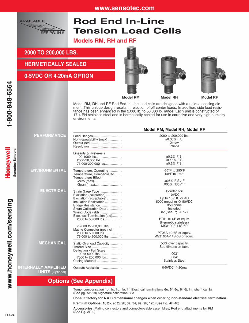
Model RM, RH and RF Rod End In-Line load cells are designed with a unique sensing ele-ment. This unique design results in rejection of off center loads. In addition, side load resis-tance has been enhanced in the 2,000 lb. to 50,000 lb. range. Each unit is constructed of 17-4 PH stainless steel and is hermetically sealed for use in corrosive and very high humidityenvironments.
Model RM, Model RH, Model RF2000 to 200,000 lbs.
±0.05% F.S.2mv/vInfinite
±0.2% F.S.±0.15% F.S.±0.2% F.S.
-65°F to 250°F60°F to 160°
.005% F.S./°F.005% Rdg./° F
Bonded foil10VDC
Up to 15VDC or AC5000 megohm @ 50VDC
350 ohmsIncluded
#2 (See Pg. AP-7)
PTIH-10-6P or equiv.(Hermetic stainless)MS3102E-14S-6P
PT06A-10-6S or equiv.MS3106A-14S-6S or equiv.
50% over capacitySee dimension table
.003"
.004"Stainless Steel
0-5VDC, 4-20ma
AVAILABLEwithSignature
CalibrationSEE PG. IN-5
Model RM Model RH Model RF
Options (See Appendix)
www.sensotec.com1-
800-
848-
6564
ww
w.h
on
eyw
ell.c
om
/sen
sin
gS
enso
tec
Sen
sors

LO-25
LO
AD
RO
D E
ND
TE
NS
ION
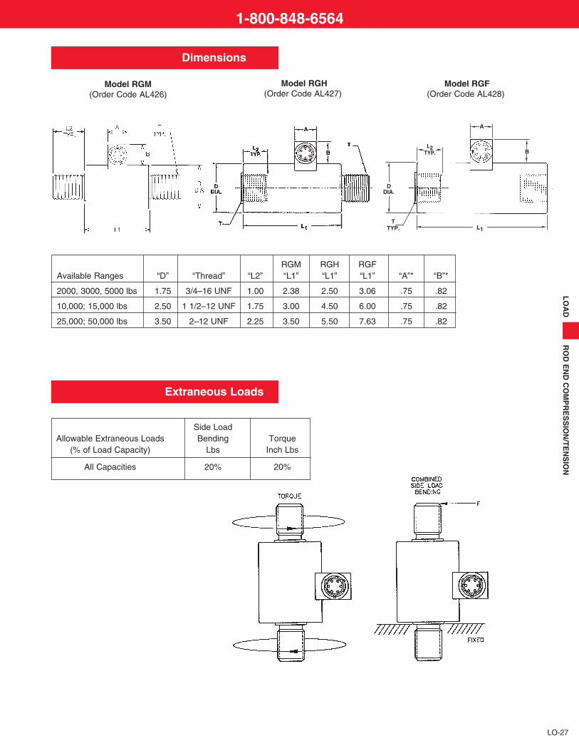
Dimensions
D"Dia.1.501.752.50
L1"4.255.007.00
A".75.75.75
B".82.82.82
L2"See bot-
tom row oforder code
chart.
OrderCodeAL414AL416AL418
k
m
n l
n l
n l
A
BL2
TYP.
L1
Model RFModel RM
k
m
DDIA.
k
T
Thread Sizes & Option Codes13a 13b 13c 13d 13e
Range 1/2-20 3/4-16 7/8-14 1-14 1-1/2-122,000 lbs. AL413 AL413 AL4133,000 lbs. AL413 AL413 AL4134,000 lbs. AL413 AL413 AL4135,000 lbs. AL413 AL413 AL4137,500 lbs. AL415 AL415 AL415 AL417
10,000 lbs. AL415 AL415 AL415 AL41715,000 lbs. AL415 AL415 AL415 AL41720,000 lbs. AL415 AL415 AL41730,000 lbs. AL41750,000 lbs. AL417
L2 Length .95" .95" .95" 1.25" 1.5"
OrderCodeAL419AL420AL424
D"Dia.1.501.752.50
L1"2.602.603.05
A".75.75.75
B".82.82.82
L2"See bottom
row oforder code
chart.
OrderCodeAL413AL415AL417
3. INDICATE THREAD SIZE: The option code for yourTHREAD SIZE is shown on the order code selection chart.
1. ORDER CODE SELECTION CHART: Locate the load range and thread required for your application on the chart below. The correct ORDER CODE is indicated where the load range and thread type intersect. Notethe option code indicated for your thread size. Highlighted order codes indicatepreferred range/thread configurations.
D"4.505.50
L1"14.0018.00
L2"3.504.50
Load Ranges75,000 lbs. or 100,000 lbs.150,000 lbs. or 200,000 lbs.
Thread Type2-1/2-12 UN3-1/2-8 UNF
D"3.504.50
L1"4.005.00
L2"3.004.00
Load Ranges75,000 lbs. or 100,000 lbs.150,000 lbs. or 200,000 lbs.
Thread Type2-1/2-12 UN3-1/2-8 UNF
Standard RangesModel RM - Male/Male
Thread Sizes & Option Codes13a 13b 13c 13d 13e
Range 1/2-20 3/4-16 7/8-14 1-14 1-1/2-12
2,000 lbs. RH AL419 AL419RF AL414 AL414
3,000 lbs.RH AL419 AL419RF AL414 AL414
4,000 lbs.RH AL419 AL419RF AL414 AL414
5,000 lbs.RH AL419 AL414RF AL414 AL414
7,500 lbs.RH AL420 AL420 AL420 AL424RF AL416 AL416 AL416 AL418
10,000 lbs.RH AL420 AL420 AL420 AL424RF AL416 AL416 AL416 AL418
15,000 lbs.RH AL420 AL420 AL420 AL424RF AL416 AL416 AL416 AL418
20,000 lbs.RH AL420 AL420 AL424RF AL416 AL416 AL418
30,000 lbs.RH AL424RF AL418
50,000 lbs.RH AL424RF AL418
L2 Length .75" .95" .95" 1.0" 1.5"
Standard RangesModel RH - Male/Female
Model RF - Female/Female
Model RH
Model RMMale/Male Frame Size Matrix Frame Size Matrix
Model RH Model RFMale/Female Female/Female
EXAMPLE: AL415
Non-standard RangesModel RM, Order Code AL411
Non-standard RangesModel RH, Order Code AL425Model RF, Order Code AL412
2. INDICATE LOAD RANGE: From the table below, choose the order code for your LOADRANGE.
EXAMPLE: AL415 EJ
EXAMPLE: AL415 EJ, 13d
Load OrderRange Code2,000............DL3,000 ...........DN4,000 ...........DP5,000 ...........DR7,500............DT
Load OrderRange Code10,000 .........DV15,000 ..........EJ20,000 ..........EL30,000 ............E50,000..........EP
Load OrderRange Code75,000 .........ER100,000........ET150,000 ........FJ200,000 ........FL
1-800-848-6564

LO-26
Temp. compensation 1b, 1c, 1d, 1e, 1f; Electrical terminations 6e, 6f, 6g, 6i, 6j; Int. shunt cal 8aSignature calibration 53e
Premium Options: 1i; 2b, 2c 2j, 2k; 3a, 3b, 3d; 9a, 9b; 12b
Accessories: Mating connectors and connector/cable assemblies; Rod end attachments for RGM
Load Ranges ................................Non-repeatability (max) ................Output (std) ..................................Resolution ....................................
Linearity & Hysteresis
Temperature, Operating ...............Temperature, Compensated ........Temperature Effect
-Zero (max)...............................-Span (max)..............................
Strain Gage Type .........................Excitation (calibration) ..................Excitation (acceptable) .................Insulation Resistance ...................Bridge Resistance ........................Shunt Calibration Data .................Wiring Code (std) .........................Electrical Termination (std)...........
Static Overload Capacity..............Deflection - Full Scale ..................Casing Material ............................
Outputs Available .........................
PERFORMANCE
ENVIRONMENTAL
ELECTRICAL
MECHANICAL
INTERNALLY AMPLIFIEDUNITS (Optional)
COMPRESSION-TENSION
2000 TO 50,000 LBS.
HERMETICALLY SEALED
0-5VDC OR 4-20MA OPTION
The Model RGM, RGH, and RGF In-Line load cells are high quality, hermetic, rugged loadcells capable of withstanding significant off-axis loads, making them an ideal choice for in-line compression measurement or tension measurement where side lading cannot be completely controlled. The flexible mounting options make applications easier to implement,and the all stainless steel, hermetic construction is well suited to corrosive and very highhumidity environments.
2000 to 50,000 lbs.±0.05% F.S.
1mV/V (nom.)Infinite
0.25% F.S.
-65°F to 250°F60°F to 160°
.005% F.S./°F.005% Rdg./° F
Bonded foil10VDC
Up to 15VDC or AC5000 megohm @ 50VDC
700 ohmsIncluded
#2 (See Pg. AP-8)PTIH-10-6P or equiv.(Hermetic stainless)
50% over capacity.003”
Stainless Steel
0-5VDC, 4-20mA
Rod End In-LineCompression-Tension Load CellsModels RGM, RGH and RGF
AVAILABLEwithSignature
CalibrationSEE PG. IN-5
Options (See Appendix)
Model RGM Model RGH Model RGF (Order Code AL426) (Order Code AL427) (Order Code AL428)
www.sensotec.com1-
800-
848-
6564
ww
w.h
on
eyw
ell.c
om
/sen
sin
gS
enso
tec
Sen
sors
LO
AD
RO
D E
ND
CO
MP
RE
SS
ION
/TE
NS
ION
LO-27
k
m
n l
n l
n l
A
BL2
TYP.
L1
Model RGF(Order Code AL428)
Model RGM(Order Code AL426)
k
Dimensions
Extraneous Loads
Model RGH(Order Code AL427)
RGM RGH RGFAvailable Ranges “D” “Thread” “L2” “L1” “L1” “L1” “A”* “B”*
2000, 3000, 5000 lbs 1.75 3/4–16 UNF 1.00 2.38 2.50 3.06 .75 .82
10,000; 15,000 lbs 2.50 1 1/2–12 UNF 1.75 3.00 4.50 6.00 .75 .82
25,000; 50,000 lbs 3.50 2–12 UNF 2.25 3.50 5.50 7.63 .75 .82
Side LoadAllowable Extraneous Loads Bending Torque
(% of Load Capacity) Lbs Inch Lbs
All Capacities 20% 20%
l
1-800-848-6564
k
m
TTYP.
DDIA.
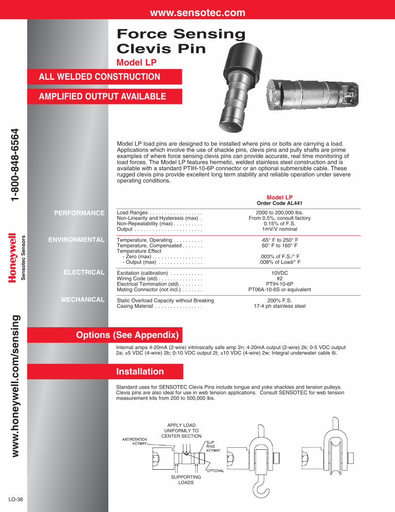
Model LP load pins are designed to be installed where pins or bolts are carrying a load.Applications which involve the use of shackle pins, clevis pins and pully shafts are primeexamples of where force sensing clevis pins can provide accurate, real time monitoring ofload forces. The Model LP features hermetic, welded stainless steel construction and isavailable with a standard PTIH-10-6P connector or an optional submersible cable. Theserugged clevis pins provide excellent long term stability and reliable operation under severeoperating conditions.
Force SensingClevis PinModel LP
ALL WELDED CONSTRUCTION
AMPLIFIED OUTPUT AVAILABLE
PERFORMANCE
ENVIRONMENTAL
ELECTRICAL
MECHANICAL
Model LPOrder Code AL441
Load Ranges . . . . . . . . . . . . . . . . . . 2000 to 200,000 lbs.Non-Linearity and Hysteresis (max) . From 0.5%, consult factoryNon-Repeatability (max) . . . . . . . . . . 0.15% of F.S.Output . . . . . . . . . . . . . . . . . . . . . . . 1mV/V nominal
Temperature, Operating . . . . . . . . . . -65° F to 250° FTemperature, Compensated . . . . . . . 60° F to 160° FTemperature Effect
- Zero (max) . . . . . . . . . . . . . . . . . .003% of F.S./° F- Output (max) . . . . . . . . . . . . . . . .008% of Load/° F
Excitation (calibration) . . . . . . . . . . . 10VDCWiring Code (std) . . . . . . . . . . . . . . . #2Electrical Termination (std) . . . . . . . . PTIH-10-6PMating Connector (not incl.) . . . . . . . PT06A-10-6S or equivalent
Static Overload Capacity without Breaking 200% F.S.Casing Material . . . . . . . . . . . . . . . . 17-4 ph stainless steel
Options (See Appendix)Internal amps 4-20mA (2-wire) intrinsically safe amp 2n; 4-20mA output (2-wire) 2k; 0-5 VDC output2a; ±5 VDC (4-wire) 2b; 0-10 VDC output 2t; ±10 VDC (4-wire) 2w; Integral underwater cable 6i.
Installation
Standard uses for SENSOTEC Clevis Pins include tongue and yoke shackles and tension pulleys.Clevis pins are also ideal for use in web tension applications. Consult SENSOTEC for web tensionmeasurement kits from 200 to 500,000 lbs.
APPLY LOADUNIFORMLY TO
CENTER SECTION
SUPPORTINGLOADS
LO-38
www.sensotec.com1-
800-
848-
6564
ww
w.h
on
eyw
ell.c
om
/sen
sin
gS
enso
tec
Sen
sors
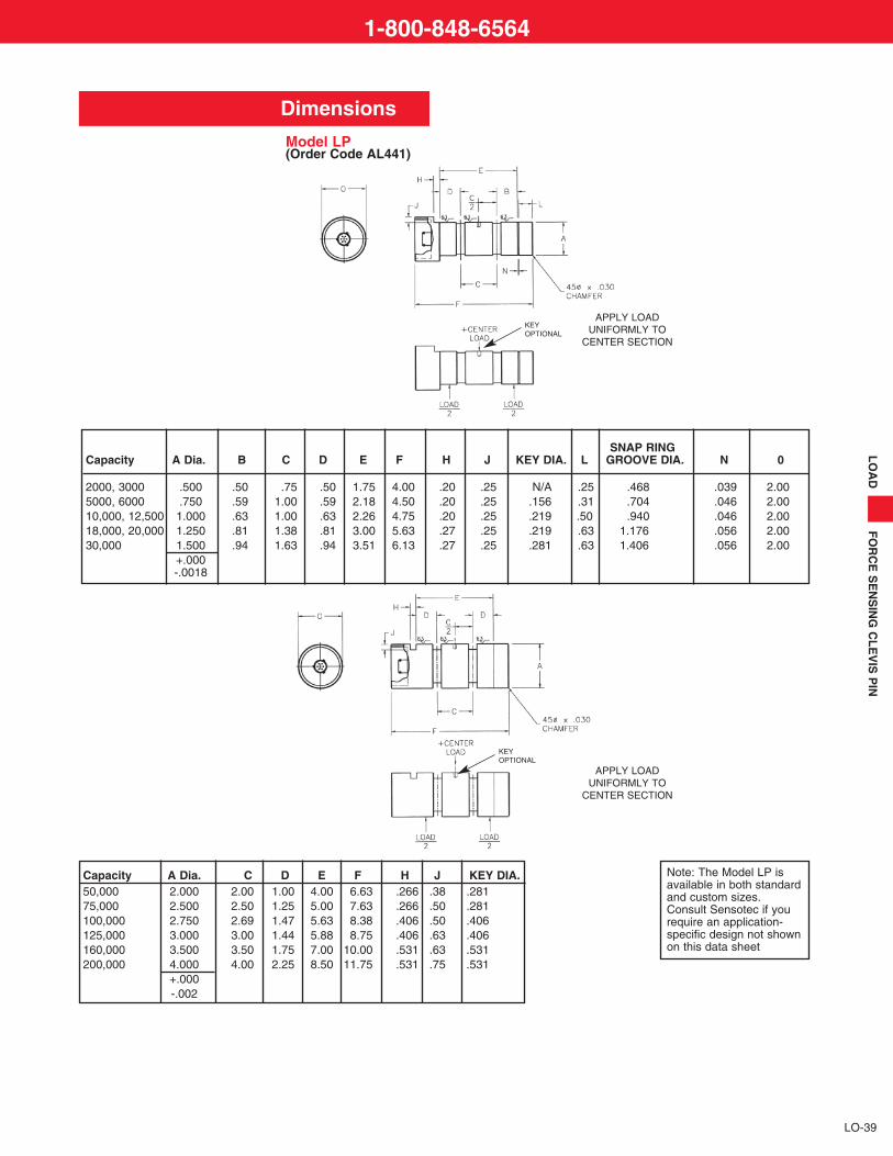
Dimensions
Model LP(Order Code AL441)
SNAP RINGCapacity A Dia. B C D E F H J KEY DIA. L GROOVE DIA. N 0
2000, 3000 .500 .50 .75 .50 1.75 4.00 .20 .25 N/A .25 .468 .039 2.005000, 6000 .750 .59 1.00 .59 2.18 4.50 .20 .25 .156 .31 .704 .046 2.0010,000, 12,500 1.000 .63 1.00 .63 2.26 4.75 .20 .25 .219 .50 .940 .046 2.0018,000, 20,000 1.250 .81 1.38 .81 3.00 5.63 .27 .25 .219 .63 1.176 .056 2.0030,000 1.500 .94 1.63 .94 3.51 6.13 .27 .25 .281 .63 1.406 .056 2.00
+.000-.0018
Capacity A Dia. C D E F H J KEY DIA.50,000 2.000 2.00 1.00 4.00 6.63 .266 .38 .28175,000 2.500 2.50 1.25 5.00 7.63 .266 .50 .281100,000 2.750 2.69 1.47 5.63 8.38 .406 .50 .406125,000 3.000 3.00 1.44 5.88 8.75 .406 .63 .406 160,000 3.500 3.50 1.75 7.00 10.00 .531 .63 .531200,000 4.000 4.00 2.25 8.50 11.75 .531 .75 .531
+.000-.002
Note: The Model LP isavailable in both standardand custom sizes.Consult Sensotec if yourequire an application-specific design not shownon this data sheet
LO
AD
FO
RC
E S
EN
SIN
G C
LE
VIS
PIN
LO-39
KEY OPTIONAL
APPLY LOADUNIFORMLY TO
CENTER SECTION
APPLY LOADUNIFORMLY TO
CENTER SECTION
KEY OPTIONAL
1-800-848-6564
Models 81 and 82 load cells combine both a compact form and high precision to offer a superiortension force transducer. The one-piece S-shaped design achieves a maximum non-linearity of0.03% full scale for load ranges from 100 to 20,000 lbs. Additional features include minimal tem-perature effects on zero and span of 0.001% and 0.0008% per degree F respectively. Models81 and 82 load cells are well suited for steelyard rod conversions. Additional applicationsinclude converting mechanical weigh bridges and platform scales into electronic scales.
Precision Tension Load CellsModels 81 and 82
LO-28
Dimensions
PERFORMANCE
ENVIRONMENTAL
ELECTRICAL
MECHANICAL
Load Ranges ................................Non-Linearity (max)......................Hysteresis.....................................Non-Repeatability (max)...............Output...........................................Resolution ....................................
Temperature, Operating ...............Temperature, Compensated ........Temperature Effect
– Zero (max).............................– Span (max)............................
Strain Gage Type .........................Excitation (calibration) ..................Bridge Resistance ........................Wiring Code (std) .........................Electrical Termination (std)...........
Static Overload Capacity..............Material
5 to 250 lbs...............................500 to 20,000 lbs......................
Model 81(Tension Only)
Order Code BL4335 to 250 lbs.±.05% F.S.±.03% F.S.±.02% F.S.
3mV/V*Infinite
0° F to 130° F30° F to 130° F
.001% F.S./ ° F.0008% Rdg./ ° F
Foil10VDC
350 ohms#1 (See Pg. AP-8)
Cable (5 ft.)
50% over capacity
AluminumN.A.
Model 82(Tension Only)
Order Code BL434100 to 20,000 lbs.
±.03% F.S.±.02% F.S.±.01% F.S.
2mV/VInfinite
0° F to 130° F30° F to 130° F
.001% F.S./ ° F.0008% Rdg./ ° F
Foil10VDC
350 ohms#1 (See Pg. AP-8)
Cable (5 ft.)
50% over capacity
AluminumStainless Steel
5 TO 20,000 lbs.
0.03% NON-LINEARITY
COMPACT SIZE
HERMETICALLY SEALED OPTION
NOTE: Optional hermetically sealed construction for Model 82 above 500 lbs.
* 5lb. output is 2mV/V.
Model 81 (Order Code BL433)
Available Ranges H” A” B” Thread5; 10; 25; 50; 100 2.38 1.7 .9 1/4-28 UNF250 2.75 1.7 .9 3/8-24 UNF
Model 82 (Order Code BL434)
Available Ranges H” A” B” Thread100; 250; 3.0 2.0 1.0 1/4-28 UNF500; 1000; 2000; 3000 3.0 2.19 .94 1/2-20 UNF5000 3.75 2.25 1.0 3/4-16 UNF10,000; 20,000 6.00 5.0 2.0 1 1/4-12 UNF
www.sensotec.com1-
800-
848-
6564
ww
w.h
on
eyw
ell.c
om
/sen
sin
g
LO
AD
DO
NU
T
Model TH Donut Shaped Load Cell features a smooth thru-hole design for use in applicationswhich require the load structure to pass through the cell. Such applications include bolt force mea-surement, post or leg mount, and rolling mill systems. Load ranges as low as 15,000 pounds andas great as 200,000 pounds can be measured within a maximum full scale non-linearity of ±0.25%F.S. This model is used in compression applications. For optimum performance, this load cell mustbe mounted between load surfaces which are flat and parallel. The Model TH Donut Shaped LoadCell is designed to provide the customer with an internal hole diameter which is large relative tothe outside diameter. The Model TH is a small size, high capacity load cell.
Donut Shaped Load CellModel TH
THRU-HOLE DESIGN
15,000-200,000 LBS.
LINEARITY TO 0.25%
LO-29
Dimensions
Options (See Appendix)
PERFORMANCE
ENVIRONMENTAL
ELECTRICAL
MECHANICAL
Temperature compensated 1b, 1c, 1f; Electrical termination 6j; Special calibration 9a, 9b
Premium Options: 1g, 1h; 12b
Model TH (Order Code BL911)Available Ranges 0.D" H" I.D."15,000; 20,000 lbs. 1.50 1.50 .7630,000; 50,000 lbs. 2.00 2.00 1.0175,000; 100,000 lbs. 2.50 2.50 1.26150,000 lbs. 3.00 3.00 1.51200,000 lbs. 3.50 3.50 1.76
Model TH(Compression Only)Order Code BL911
Load Ranges ................................ 15,000 to 200,000 lbs.Non-linearity (max) ....................... ±0.25% F.S.Hysteresis (max) .......................... ±0.25% F.S.Non-repeatability (max) ................ ±0.1% F.S.Output........................................... 2mV/VResolution .................................... Infinite
Temperature, Operating ............... -65° F to 250° FTemperature, Compensated ........ 60° F to 160° FTemperature Effect
- Zero (max) ............................. .005% F.S./° F- Span (max) ............................ .005% Rdg./° F
Strain Gage Type ......................... Bonded FoilExcitation (calibration) .................. 10VDC NOMBridge Resistance ........................ 350 ohmsWiring Code (std) ......................... #1 (See Pg. AP-8)Electrical Termination (std)........... Teflon cable (5ft.)
Static Overload Capacity.............. 50% over capacityCasing Material ............................ Stainless steelDeflection—Full Scale .................. .0025"
Model TH (Compression Only)
1-800-848-6564

The Model D Donut Shaped Load Cell features a smooth thru-hole design perfect for applica-tions which require the load structure to pass directly through the cell. Such applications includebolt force measurements, clamping forces, and monitoring overloads. Load ranges as low as150 grams and as great as 30,000 pounds can be measured within a maximum full scale non-linearity and hysteresis of ±0.5% F.S. These models are used in compression applications andare available in multiple hole sizes. For optimum performance, these cells must be mountedbetween load surfaces which are flat and parallel. The Model D miniature load cell is designedto have a minimum thickness.
Donut Shaped Load CellsModel D
THRU-HOLE DESIGN
150 GMS - 30,000 LBS.
FLEXIBLE DESIGN
LO-32
Dimensions
Options (See Appendix)
PERFORMANCE
ENVIRONMENTAL
ELECTRICAL
MECHANICAL
Temperature compensated 1b, 1c, 1f; Special calibration 9a, 9b
Premium Options: 1g (≥5 lb. only); 12b
Model D (Order Code BL912)Selection Guide—150 gms. to 100 lbs. unitsAvailable Ranges O.D.” I.D.” H” Excitation150; 250; 500; 1000 gms .50 .10 .15 5VDC5; 10 lbs. 1.00 .20 .28 10VDC25; 50; 100 lbs. 1.00 .20 .28 10VDC
Model D(Compression Only)
Load Ranges ................................ 150 gms to 30,000 lbs.Non-linearity and Hysteresis (max) ±0.5% F.S.Non-repeatability (max) ................ ±0.1% F.S.Output........................................... 20mV/V (gram units)
2mV/V (5 lb. and above)Resolution .................................... Infinite
Temperature, Operating ............... -65° F to 250° FTemperature, Compensated ........ 60° F to 160° FTemperature Effect
- Zero (max) ............................. .005% F.S./° F (5 lb. and above); .01%/° F (gram units)- Span (max) ............................ .010% Rdg./° F (5 lb. and above); .02%/° F (gram units)
Strain Gage Type ......................... Semi conductor (gram units)Bonded foil (5 lb. and above)
Excitation (calibration) .................. Semi conductor 5VBonded foil 10V
Bridge Resistance ........................ 500 ohms (gram units)350 ohms (5 lb. and above)
Wiring Code (std) ......................... #1 (See Pg. AP-8)Electrical Termination (std)........... Teflon cable (5 ft.)
Overload, Safe ............................. 50% over capacityCasing Material ............................ Stainless Steel
Model D (Compression Only)
www.sensotec.com1-
800-
848-
6564
ww
w.h
on
eyw
ell.c
om
/sen
sin
g
LO
AD
DO
NU
T
Selection Instructions for Larger Capacity Units—30,000 lbs.
Shown below are three separate outline drawings for the Model D Load Cell. The frame sizeselection guide below indicates that with a single shell size (outside diameter), different “donutholes” are available. For example, in the small frame size (A) it is possible to select a 250 lb. loadcell with a nominal hole size of 1/8" (P), 3/16" (Q), 1/4" (R), or 3/8" (S) diameter. We manufacturethe actual hole dimensions to provide some clearance; for example the 1/8" (P) diameter dimen-sion, the actual dimension is 0.128".
LO-33
Frame Size Selection Guide
Options
HOW TO ORDER: SPECIAL ORDER INSTRUCTIONS
1. Specify the order code (See frame size A, B or C)2. State the load range required in pounds and range code.3. State the nominal hole diameter letter.
e.g. Model D: BL914CN R (1/4 inch) [250 lbs.]
Hole Letters P Q R S T V W Y Z
Nominal Hole Dia. 1/8" 3/16" 1/4" 3/8" 1/2" 5/8" 3/4" 1" 1 -1/4"
Actual Hole Dia. .128" .193" .266" .391" .532" .656" .781" 1.032" 1.281"
100 lbs. A A A A
250 lbs. A or B A or B A or B A or B B B
500 lbs. A or B A or B A or B A or B B B
1,000 lbs. A or B A or B A or B B B B
2,000 lbs. A, B or C A, B or C A, B or C B or C B or C B or C C C C
3,000 lbs. B or C B or C B or C B or C B or C C C C C
5,000 lbs. B or C B or C B or C B or C B or C C C C C
7,500 lbs. B or C B or C B or C B or C B or C C C C C
10,000 lbs. B or C B or C B or C B or C B or C C C C C
15,000 lbs. C C C C C C C C C
20,000 lbs. C C C C C C C C C
30,000 lbs. C C C C C C C C C
*Choose Hole Dia. fromSelection Guide above.
FRAME SIZE AORDER CODE BL913 FRAME SIZE B
ORDER CODE BL914
FRAME SIZE CORDER CODE BL915
1-800-848-6564
Models MBL and MBH Minigram Beam Load Cells are engineered to measure very low bendingforces and still achieve an impressive 0.1% full scale non-linearity and hysteresis. Built-in over-load stops are incorporated to provide additional reliability. Miniature dimensions allow easy unitintegration into existing systems. Model MBL uses semiconductor gages and is available forload ranges from 25 to 1000 grams. Model MBH uses foil gages and is available for load rangesfrom 150 grams to 10 lbs.
Minigram Beam Load CellsModels MBL and MBH
25 GMS TO 10 LBS.
MINIATURE SIZE
LO-34
Dimensions
Options (See Appendix)
PERFORMANCE
ENVIRONMENTAL
ELECTRICAL
MECHANICAL
Temperature compensation 1b; 1c; 1f.
Premium Options: 1i; 6d; 9a
Model MBL Model MBHOrder Code BL341 Order Code BL342
Load Ranges ................................ 25 gms to 1000 gms 150 gms to 10 lbsNon-Linearity and
Hysteresis (max) ...................... ±0.1% F.S. ±0.1% F.S.Non-Repeatability (max)............... ±0.03% F.S. ±0.03% F.S.Output........................................... 20mV/V 2mV/VResolution .................................... Infinite Infinite
Temperature, Operating ............... 0° F to 200° F 0° F to 200° FTemperature, Compensated ........ 60° F to 160° F 60° F to 160° FTemperature Effect
- Zero (max) ............................. .015% F.S./° F .005% F.S./° F- Span (max) ............................ .02% Rdg./° F .005% Rdg./° F
Strain Gage Type ......................... Bonded semiconductor Bonded foilExcitation...................................... 5VDC 5VDCBridge Resistance ........................ 500 ohms 350 ohmsWiring Code (std) ......................... #1 (See Pg. AP-8) #1 (See Pg. AP-8)Electrical Termination (std)........... Cable (5 ft.) Cable (5 ft.)
Overload, Safe 400% over capacity 400% over capacity or 20 lbs., whichever is less
Model MBL/Model MBH
Available Ranges
Model MBL (Order Code BL341)25; 50; 100; 150; 250; 500; 1000 gms
Model MBH (Order Code BL342)150; 250; 500; 1000 gms; 5; 10 lbs.
Model MBL or Model MBH
www.sensotec.com1-
800-
848-
6564
ww
w.h
on
eyw
ell.c
om
/sen
sin
g