CH.2 Tension & COMPRESSION LIU Jiemin @SJZU 20081.
49
LIU Jiemin @SJZU 2008 1 CH.2 Tension & COMPRESSION
-
Upload
myles-lenard-todd -
Category
Documents
-
view
229 -
download
4
Transcript of CH.2 Tension & COMPRESSION LIU Jiemin @SJZU 20081.

LIU Jiemin @SJZU 2008 1CH.2 Tension & COMPRESSION

LIU Jiemin @SJZU 2008 2CH.2 Tension & COMPRESSION
Chapter 2 Stress under axial loading,
Mechanical properties of materials
Chapter 2 Stress under axial loading,
Mechanical properties of materials
2.1 Introduction
2.2 Axial force and axial diagrams
2.3 Stress in an axially loaded rod
2.4 Mechanical properties of materials
2.5 Stress concentration
2.6 Allowable stress and strength criteria
2.7 Stress and strength in connections

LIU Jiemin@SJZU 2008 3CH.2 TENSION & COMPRESSION
Characteristic of loads :Acting line of external forces coincides with the axle
Tension and compression along axle
Characteristic of deformation :Elongation or compression along axle, accompany contraction or dilation
F F
F F
2.1 Introduction

LIU Jiemin @SJZU 2008 4CH.2 Tension & COMPRESSION
Chapter 2 Stress under axial loading,
Mechanical properties of materials
Chapter 2 Stress under axial loading,
Mechanical properties of materials
2.1 Introduction
2.2 Axial force and axial diagrams
2.3 Stress in an axially loaded rod
2.4 Mechanical properties of materials
2.5 Stress concentration
2.6 Allowable stress and strength criteria
2.7 Stress and strength in connections

LIU Jiemin@SJZU 2008 5CH.2 TENSION & COMPRESSION
2.2.1 Axial force — FN, Internal force acting on cross-section along the axle , determined by cross-section method.
0FF:0F Nx 2.2.2 Symbol of axial force
FFA
A
NFF
FN<0
FNFNFN FN
FN>0
2.2 Axial force and axial diagrams

LIU Jiemin@SJZU 2008 6CH.2 TENSION & COMPRESSION
N xF F F Axial force is equal to sum of all axial forces acting on one side of the section
FFA
A
NFF
2.2.3 Determine FN by simple cross-section method
2.2 Axial force and axial diagrams

LIU Jiemin@SJZU 2008 7CH.2 TENSION & COMPRESSION
① 反映出轴力与截面位置变化关系,较直观;② 确定出最大轴力的数值及其所在横截面的位置,即确定危险截面位置,为强度计算提供依据。
2.2.4 Axial force diagram
意义意义
FFA
AFN
xF
+
2.2 Axial force and axial diagrams

LIU Jiemin@SJZU 2008 8CH.2 TENSION & COMPRESSION
Ex.1 The rod is subjected to forces of 5kN, 8kN, 4kN and 1kN at points A, B, C and D as shown. Drawing the axial-force diagram.
Solution : FN1 in portion OA :
0 xF 0 1485F 1N
2kNF 1N
A B C D
5kN 8kN 4kN 1kN
O
A B C D
5kN 8kN 4kN 1kN
FN1
Simple section method,please!
2.2 Axial force and axial diagrams

LIU Jiemin@SJZU 2008 9CH.2 TENSION & COMPRESSION
By the same token , axial forces in portion AB 、 BC 、CD:
xFN/kN2
3
5
1++–
FN2= –3kNA B C D
5kN 8kN 4kN 1kN
O 2
2
FN3= 5kNA B C D
5kN 8kN 4kN 1kN
O 3
3
FN4 =1kNA B C D
5kN 8kN 4kN 1kN
O 4
4Axial force diagram:
2.2 Axial force and axial diagrams

LIU Jiemin @SJZU 2008 10CH.2 Tension & COMPRESSION
Chapter 2 Stress under axial loading,
Mechanical properties of materials
Chapter 2 Stress under axial loading,
Mechanical properties of materials
2.1 Introduction
2.2 Axial force and axial diagrams
2.3 Stress in an axially loaded rod
2.4 Mechanical properties of materials
2.5 Stress concentration
2.6 Allowable stress and strength criteria
2.7 Stress and strength in connections

LIU Jiemin@SJZU 2008 11CH.2 TENSION & COMPRESSION
2.3.1 Stress on cross-section
FFN(x)
A
xFN )(
AN dAxF )(
Assumption: Stress distributs uniformly on crose-section
F F
2.3 Stress in an axially loaded bar,
Saint-venant’ principle

LIU Jiemin@SJZU 2008 12CH.2 TENSION & COMPRESSION
Plane assumotion: Cross-sections transit along axle and hold as plane
2.3.2. Plane assumotion
d ´a´c´
b´
a bc d
F F
Axial strains are the same , and normal stresses distribute uniformly
2.3 Stress in an axially loaded bar,
Saint-venant’ principle

LIU Jiemin@SJZU 2008 13CH.2 TENSION & COMPRESSION
2.3.3 Stress on oblique-section
F=F
A
Fp
cos cos
AA
A
A
coscos 0
A
F
A
Fp
A rod is subjected to F, find stresses on the k-k section
k
k
FF
FF pSolution:
2.3 Stress in an axially loaded bar,
Saint-venant’ principle

LIU Jiemin@SJZU 2008 14CH.2 TENSION & COMPRESSION
cos0p
20coscos p
0 22
p sin sin
min90 0 0,, ,
00: , =0 ,max
Maximum normal stress on cross-section , maximum normal stress on 45° inclined-section
0 045 2, = 2,max, / /
p
FF p
Stresses on typiocal sections
2.3 Stress in an axially loaded bar,
Saint-venant’ principle

LIU Jiemin@SJZU 2008 15CH.2 TENSION & COMPRESSION
MPamax / . / . 0 2 127 4 2 63 7
0 127 4( ) ( ) MPa
2 2
.
oσ 1+ cos2a 1+ cos60 95.5
MPa.
sin . 0 127 4
sin2α 60 55 22 2
MPaF
.A .
0 2
4 10000127 4
3 14 10
Ex.4 A rod of diameter d =1 cm , F =10 kN , determine maximum sheari
ng stress , and normal stress and shearing stress on 30°inclined section.
Solution:
k
k
FF
2.3 Stress in an axially loaded bar,
Saint-venant’ principle

LIU Jiemin @SJZU 2008 16CH.2 Tension & COMPRESSION
Chapter 2 Stress under axial loading,
Mechanical properties of materials
Chapter 2 Stress under axial loading,
Mechanical properties of materials
2.1 Introduction
2.2 Axial force and axial diagrams
2.3 Stress in an axially loaded rod
2.4 Mechanical properties of materials
2.5 Stress concentration
2.6 Allowable stress and strength criteria
2.7 Stress and strength in connections

LIU Jiemin@SJZU 2008 17CH.2 TENSION & COMPRESSION
Conditions : ☆ Commen temprature(20℃) ☆ Static load
• Strength• Stiffness• Stability
• External forces• Size of member• Configration
Mechanical properties
Standard Specimen
l
d
2.4 Mechanical Properties of Mild Steel
LIU Jiemin@SJZU 2008 18CH.2 TENSION & COMPRESSION
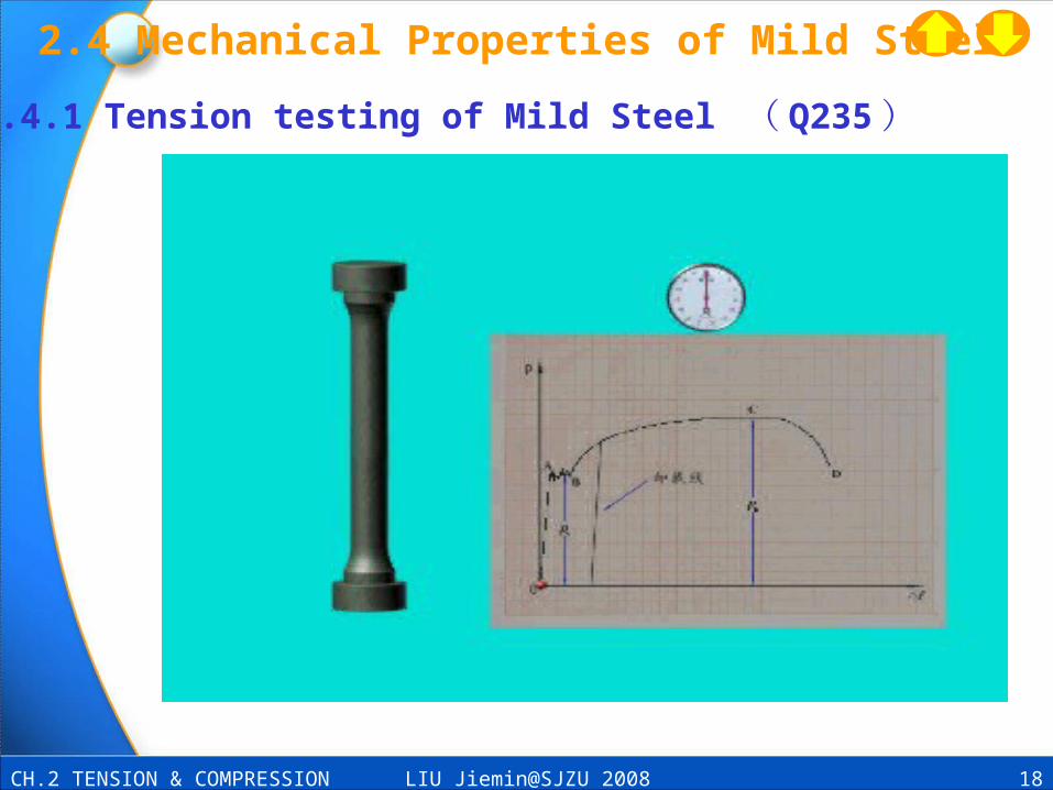
2.4.1 Tension testing of Mild Steel ( Q235 )
2.4 Mechanical Properties of Mild Steel

LIU Jiemin@SJZU 2008 19CH.2 TENSION & COMPRESSION
F
OP- L curve△
F
F
△L
A
F,
L
ΔL
2.4.2. Curve of F-ΔL for Mild Steel
2.4 Mechanical Properties of Mild Steel

LIU Jiemin@SJZU 2008 20CH.2 TENSION & COMPRESSION
O -curve
2.4.3 Stress-Strain curve (Elastic portion)
Hooke LAWE ,
ea
p
b
2.4 Mechanical Properties of Mild Steel
ob: elasticity portion
oa: proportional portion
ab: non-proportional portion

LIU Jiemin@SJZU 2008 21CH.2 TENSION & COMPRESSION
-curve
O
pe
b c
Ultimate stress b
e
d
2.4.3 Stress-Strain curve (Yielding and Strenthening portions)
f
s
s Yield stressb
2.4 Mechanical Properties of Mild Steel
bc : Yield portion
ce : Strengthening portion
ef : Necking portion
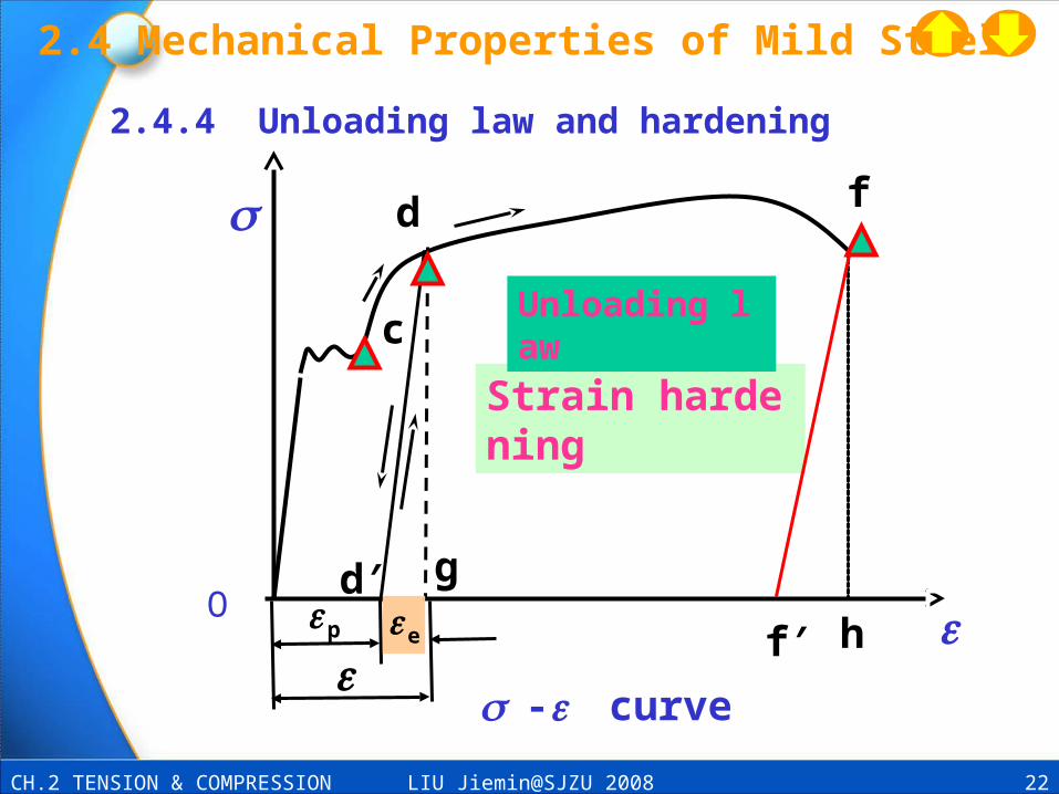
LIU Jiemin@SJZU 2008 22CH.2 TENSION & COMPRESSION
O
c
f
-curve
d′ g
f′ h
Strain hardening
d
Unloading law
ep
2.4.4 Unloading law and hardening
2.4 Mechanical Properties of Mild Steel
LIU Jiemin@SJZU 2008 23CH.2 TENSION & COMPRESSION
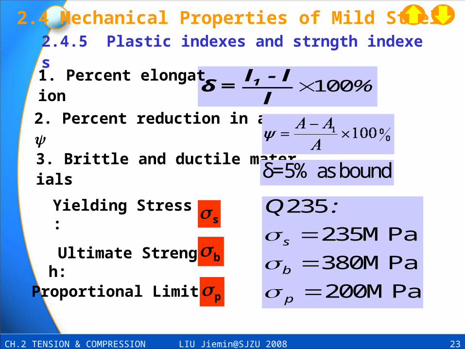
100%1l - lδ =
l
2. Percent reduction in area :
3. Brittle and ductile materials
1. Percent elongation
2.4.5 Plastic indexes and strngth indexes
Yielding Stress: s
Ultimate Strength: b
Proportional Limit: p
235
235MPa
380MPa
200MPa
s
b
p
Q :
δ=5% as bound
2.4 Mechanical Properties of Mild Steel

LIU Jiemin@SJZU 2008 24CH.2 TENSION & COMPRESSION
O
Hard Alu.
20.
0.2% Mild Steel C.
O
Com.
F
F
s
Tension
2.4.6 σ0.2 and compression of mild steel
2.4 Mechanical Properties of Mild Steel

LIU Jiemin @SJZU 2008 25CH.2 Tension & COMPRESSION
Chapter 2 Stress under axial loading,
Mechanical properties of materials
Chapter 2 Stress under axial loading,
Mechanical properties of materials
2.1 Introduction
2.2 Axial force and axial diagrams
2.3 Stress in an axially loaded rod
2.4 Mechanical properties of materials
2.5 Stress concentration
2.6 Allowable stress and strength criteria
2.7 Stress and strength in connections

LIU Jiemin@SJZU 2008 26CH.2 TENSION & COMPRESSION
在集中力和截面尺寸突变处,变形和应力急剧变大的现象。
外力的分布方式只影响作用区域附近的应力分布,离开载荷作用区域一定距离,应力分布与大小几乎不受外载荷作用方式的影响。
b c
Fc
aStrain Distribution
Stress Distribution
F bamax
n
max
k
FF
2.5 Stress concentration;
Saint-venant’ principle

LIU Jiemin @SJZU 2008 27CH.2 Tension & COMPRESSION
Chapter 2 Stress under axial loading,
Mechanical properties of materials
Chapter 2 Stress under axial loading,
Mechanical properties of materials
2.1 Introduction
2.2 Axial force and axial diagrams
2.3 Stress in an axially loaded rod
2.4 Mechanical properties of materials
2.5 Stress concentration
2.6 Allowable stress and strength criteria
2.7 Stress and strength in connections

LIU Jiemin@SJZU 2008 28CH.2 TENSION & COMPRESSION
2.6 Allowable Stress and Strength Design
uσ > σ (Ul timate stress)
[]—Allowable stress, n-Safety factor
②Design:][
maxmin
,NFA
][ AFN
2.6.1 Failure and Allowable stress
max①Check :
③Allowable load :
n
u
2.6.2 Stength Condition )( maxmax A
FN
Failure

LIU Jiemin@SJZU 2008 29CH.2 TENSION & COMPRESSION
Ex. 4 A rod of diameter d =14mm is subjecte to a axial load F =
25 k N, []=170MPa , check the strength of the rod.
Solution :① Axial force : FN = F =25kN
MPa1620140143
1025442
3
2
..πd
P
A
FNmax②Stress :
③Check : 170MPa162MPamax
④Conclusion : Safety.
l
dF F
2.6 Allowable Stress and Strength Design

LIU Jiemin@SJZU 2008 30CH.2 TENSION & COMPRESSION
Ex. 5 A simple crane is shown in Fig.. Knowing that length of the rigid beam AC, L=2m, h=1m = 45◦ and allowable stress []=160 MPa. Find allowable load [F].
L
h
F
A
BC
D
2.6 Allowable Stress and Strength Design

LIU Jiemin@SJZU 2008 31CH.2 TENSION & COMPRESSION
M , ( ) ( )A L N0 F sinθ hctgθ F 0N
FLF =
hcosθ
N
LF A , F A
hcos
Find [F]
Find FN
FAy
FAx
FN
L
F
A B
C
Solution:
kN
d hcosF .
L
2 220 1 160 235 5
4 4 2 2
2.6 Allowable Stress and Strength Design

LIU Jiemin@SJZU 2008 32CH.2 TENSION & COMPRESSION
Ex. 5 A simple crane is shown in Fig.. Find angle at such state, rod BD is lightest. Knowing that total weight of the body F and allowable stress [].
xL
h
F
A B
C
D
2.6 Allowable Stress and Strength Design

LIU Jiemin@SJZU 2008 33CH.2 TENSION & COMPRESSION
M , ( ) ( )A N0 F sinθ hctgθ Fx 0
cosh
LFF max,N
hcos
LFFA maxN , Area of BD
:
For DC , Axial force FN
FAy
FAx
FN
xL
F
A B
C
2.6 Allowable Stress and Strength Design
Solution :

LIU Jiemin@SJZU 2008 34CH.2 TENSION & COMPRESSION
③Determine minimum value of VBD :
;sin [ ] sin
BDBD
L BD
A h 2FV = A L
θ σ 2θ
][ L2F
V , mino 时45
sin/BDL h θBD BDV = A L
2.6 Allowable Stress and Strength Design

LIU Jiemin@SJZU 2008 35CH.2 TENSION & COMPRESSION
[ 例 6] 已知三铰屋架如图,承受竖向均布载荷,载荷的分布集度为: q =4.2kN/m ,屋架中的钢拉杆直径 d =16 mm ,许用应力 []=170M Pa 。试校核刚拉杆的强度。
钢拉杆
4.2m
q
8.5m
2.6 Allowable Stress and Strength Design

LIU Jiemin@SJZU 2008 36CH.2 TENSION & COMPRESSION
① 整体平衡求支反力解:
钢拉杆
8.5m
q
4.2m
FRA RB
FA
kN. Fm
FX
ARB
A
5190
00
2.6 Allowable Stress and Strength Design

LIU Jiemin@SJZU 2008 37CH.2 TENSION & COMPRESSION
③ 应力:
④ 强度校核与结论: MPa 170 MPa 131 max
此杆满足强度要求,是安全的。
MPa1310160143
103264
4
2
3
..
.
d
P
A
F
2N
max
② 局部平衡求 轴力: q
RC
HC
FN
kN. Fm NC 3260
FRA
FA
2.6 Allowable Stress and Strength Design

LIU Jiemin@SJZU 2008 38CH.2 TENSION & COMPRESSION
例 7 图示拉杆沿 mn 由两部分胶合而成 , 受力 P ,设胶合面的许用拉应力为 []=100MPa ;许用剪应力为 []=50MPa ,并设杆的强度由胶合面控制 , 杆的横截面积为 A= 4cm² ,试问 : 为使杆承受最大拉力 , 角值应为多大 ?( 规定 : 在 0~60 度之间 ) 。
kN50,6.26 BB P
联立 (1)、 (2)得:
P Pm
n
解:)1( ][cos2
A
P
)2( ][cossin A
PP
6030
B
2.6 Allowable Stress and Strength Design

LIU Jiemin@SJZU 2008 39CH.2 TENSION & COMPRESSION
( ) kNP A / cos sin / . 260 60 60 4 50 10 4 3 46 2
kN50maxP
(1)、 (2)式的曲线如图 (2),显然, B 点左 侧由正应力控制杆
的强度, B点右侧由切应力控制杆的强度,当 =60°时,由 (2)
式得
kN44.553/41060460sin/60/cos 260,1
APB
kN44.55maxP
解 (1)、 (2)曲线交点处:
kN4.54;3111 BB P
?;MPa60][ max P讨论:若
P
6030
B
2.6 Allowable Stress and Strength Design

LIU Jiemin @SJZU 2008 40CH.2 Tension & COMPRESSION
Chapter 2 Stress under axial loading,
Mechanical properties of materials
Chapter 2 Stress under axial loading,
Mechanical properties of materials
2.1 Introduction
2.2 Axial force and axial diagrams
2.3 Stress in an axially loaded rod
2.4 Mechanical properties of materials
2.5 Stress concentration
2.6 Allowable stress and strength criteria
2.8 Stress and strength in connections

LIU Jiemin@SJZU 2008 41CH.2 TENSION & COMPRESSION
2.8.1 Charactristics of external forces ang deformations
1. Connections
Connections connecting other members
FF
Bold connection
2.8 Stress and strength in connections
FF
Rivet

LIU Jiemin@SJZU 2008 42CH.2 TENSION & COMPRESSION
m
Shaft
Key
Gear wheel
Charactristic : Trasnsmission torque 。
2.8 Stress and strength in connections
LIU Jiemin@SJZU 2008 43CH.2 TENSION & COMPRESSION
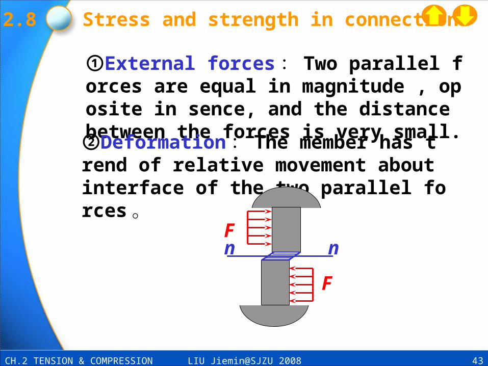
①External forces : Two parallel forces are equal in magnitude , oposite in sence, and the distance between the forces is very small.
②Deformation : The member has trend of relative movement about interface of the two parallel forces 。
n nF
F
2.8 Stress and strength in connections

LIU Jiemin@SJZU 2008 44CH.2 TENSION & COMPRESSION
③Shearing surface : n– n
④Internal force in the shearing surface:Shear force Fs , parallet to the shear surface
F
F
n nn n
Fs
Shear surface
F
2.8 Stress and strength in connections
n n
LIU Jiemin@SJZU 2008 45CH.2 TENSION & COMPRESSION
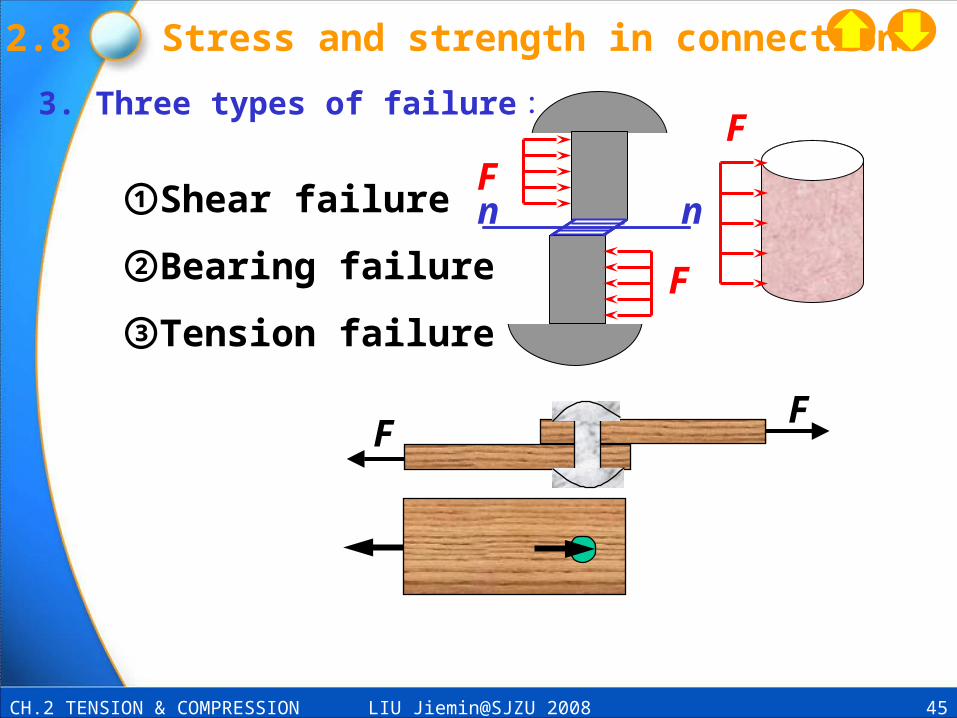
①Shear failure
②Bearing failure
③Tension failure
FF
n nF
F
F3. Three types of failure :
2.8 Stress and strength in connections

LIU Jiemin@SJZU 2008 46CH.2 TENSION & COMPRESSION
1. Shear surface-As : Shear force--Fs :
2 Nomonal shear stress- :
3 Strength condition of shear
4. Assumption calculation of shear
n nFs
Fs
s
s
A
F
][ s
s
A
F
n nFs
Shear surfae
Fs
2.8 Stress and strength in connections

LIU Jiemin@SJZU 2008 47CH.2 TENSION & COMPRESSION
5. Bearing stressσbs
Bearing force―Fbs (bearing surface)
FbsFbs
Effective area of the bearing surface =dt
][ bsbs
bsbs td
F
A
F
2.8 Stress and strength in connections
Effective area
Effective area

LIU Jiemin@SJZU 2008 48CH.2 TENSION & COMPRESSION
Ex.2.7 Determine diameter d of the bold. Knowing:F=200kN ,t=20mm , [] =80MPa , [bs]=200MPa.
Solution :
Fs
Shear surface
Fs
F/2F
t/2
t
F/2 t/2
Fs
][
2
s
s
d
4
2
F
A
F
40mm1080
1020022Fd
6
3
][
][ bsbs
bsbs td
F
A
F
50mm20020
200000
t
F'd
bs
][
50mmd
2.8 Stress and strength in connections

LIU Jiemin@SJZU 2008 49CH.2 TENSION & COMPRESSION