HEWLETT PACKARD Cb~~...
23
L OW LEVEL PREAMPLIFIER MODELS 150-1500 , 150- 1500A iM-150-1500 -1 IN STRUCTION MANUAL HEWLETT __ PACKA RD SANBORN DIVISION
Transcript of HEWLETT PACKARD Cb~~...

LOW LEVEL PREAMPLIFIER
MODELS 150-1500 , 150- 1500A
iM-150-1 500-1
IN STRUCTION MANUAL
HEWLETT __ PACKARD Cb~ ~ SANBORN
DIVISION
INSTRUCTION MANUAL
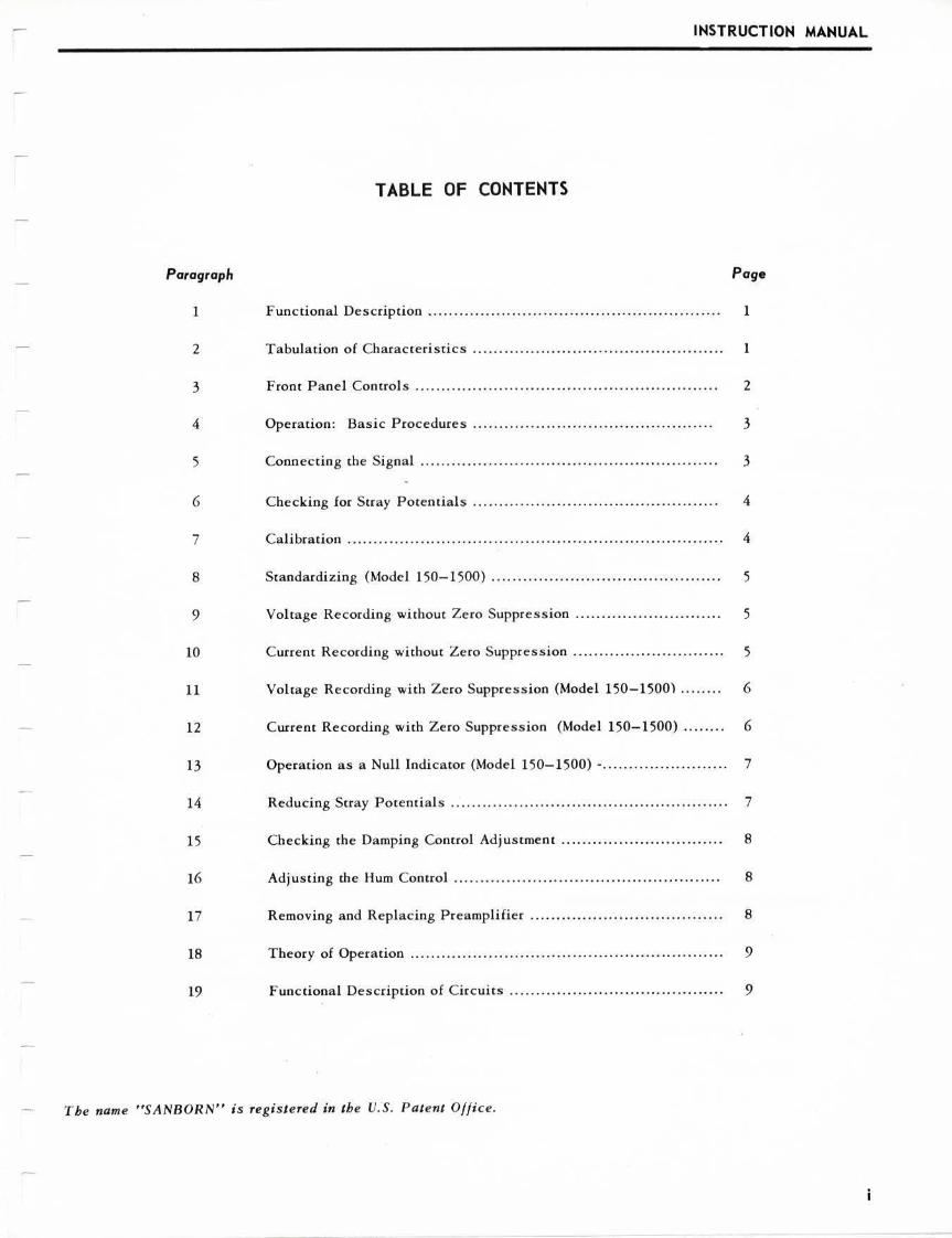
TABLE OF CONTENTS
Paragraph Page
1 F unctional Description . . . . . . . . . . . . . . . . . . . . .. . . . . . .. . . .. . . .. . . . . . .. . . . . . . . . .. . . 1
2 Tabulation of Characteristics . ..... .. .. .. ... .... ..... ... ....... .. .. ....... ... 1
3 Front Panel Controls . . . . .. .. .. .. .. . .. .. .. . . .. .. .. .. . . . .. . . .. .. .. . .. . . .. . . . . . . . 2
4 Operation: Basic Procedures .. . . . . . . .. . . . ... .. . . . . .. .. . . . ... .. .. .. .. . . . .. . 3
5 Connecting the Signal . .. . . .. . . . . . . . . . .. . . . .. . .. . . . . . . . . . . .. . . . . . . . . . . .. .. . . . .. 3
6 Checki ng for Stray Potentials .. .. .. . . .. .. .. . . .. . .. .. .. .. .. . . . . . . . . .. . .. .. . .. 4
7 Cal ibration . . .. . . . . . . . .. . . .. . . .. .. .. . . . . .. .. . . . . . .. . . . .. . . . . . . . . . . . .. . . . . . . .. . . . . . . 4
8 Standardizing (Model 150-1500) . ...... ................ .. ..... .. .. .......... 5
9 Vol tage Recording without Zero Suppression .. .. .. .. .. . .. .. . . . .. . . . .. . . . 5
10 Current Recording wi thout Zero Suppression . . .. .. .. .. .. . .. . .. .. . .. . . . . . . 5
11 Voltage Recording with Zero Suppression (Model 150-1500) .. .... .. 6
12 Current Recording wi th Zero Suppression (Model 150-1500) ........ 6
13 Operation as a Null Indicator (Model 150-1500) -. . . .. .. . ....... . ..... .. . 7
14 Reducing Stray Potentials .. . . . .. . . .. . . . . . . .. . . . .. ... .. .. . . ... . .. .. . . .. .. . . . .. . 7
15 Checking the Damping Control Adjustment ..... ......... . ...... ... ....... 8
16 Adj usting the Hum Control .. .. . .. . .. . . . . . .. . .. . . . .. . . . . . . . .. . ... . .. . .. .. . . . . . 8
17 Removing and Replacing Preamplifier . .. .. . . .. . . . . . . . . . . . . .. . .. . . .. . . . . .. . 8
18 Theory of Operation . . . . .. . . . . . . . . . . . . . . . . . . . . .. . . . . . .. . . . . . . . . . . . . . . . . . . . . . . . . . 9
19 Functiona l Description of Circuits .. . . .. . . . . . .. . .. .. . . . . .. .. . .. .. .... . . . .. . 9
The name "SANBORN" is registered in the U.S. Patent Office.

HP Archive
This vintage Hewlett Packard document was preserved and distributed by
www.hparchive.com
Please visit us on the web !
Prepared by on-line curator: Tony Gerbic
For FREE Distribution Only ***

SANBORN LOW LEVEL PREAMPLIFIER MODELS 150-1500, 150-1500A
INSTRUCTION MANUAL
SANBORN LOW LEVEL PREAMPLIFIER
Mode Is 150- 1500 and 150-1500A
1. FUNCTIONAL DESCRIPTION
The Sanborn Low Level Preampl ifie r is a chopper type of amplifier for measuring slowly varying direcr voltages, or meas uring slowly varying curreocs by adding an exrernal s hunt res istor. These signals may be read in c ircuits removed from ground by as much as 300 volts DC. Model 150-1500 includes a ZERO SUPPRESSION circuit, which is omitted in Model 150-1 500A. This manual applies to the P reamplifier whi ch uses an improved chopper c ircuit, identified by the HUM control on the Croor panel, starring wich s erial no. 200.
110
100
z 90 0 ;:: u 80 ~ u.. w 0
70 j ~ 60 g
~ so z 0 CL V'I
~ 40
~ ~ 30 a:: w CL
20
10
0 0.5
-r--r---- I'-.
't-,
r-..
"" \ ~ / I\ I y I \ I
I INPl'T SIGNAi I
I I
'O m.tt><
I\ .
2 10 20 so 100
FREQUENCY IN CYCLES PER SECOND
Figure 1. Combined Respons e Choracteristics o f Sanborn Low Level Preamplifier, Driver Amplifier , ancl Galvanomete r.
2. TABULATION OF CHARACTERISTICS
SENSITIV ITY
FREQUENCY RANGE
RISE TIM E
100 mi crovolts per ce ntimeter co 0. 1 volt per centimeter, in ten steps with panel-mounted ATTENUATOR. With external 100 ohm resiscor, measures LO microampere per ce ntimeter co 1.0 milli ampere per cenrimecer.
Three decibels down ac 15 cycles . See fig. 1.
0 .03 seconds . Defined as rime required to reac h final deflection, as measured by besc straight line approximation to che initi a l rise of the response co unit step input. See fig. 1.

INSTRUCTION MANUAL
2. TABULATION OF CHARACTERISTICS (Cont .)
INPUT IMPEDANCE
SOURCE IMPEDANC E
DRIFT
OVERLOAD
ATTENUATOR ERROR
CALIBRATION
ZERO SUPPRE5.510N
RIPPLE
3. FRONT PANEL CONTROLS
POSITION
SENSITIVITY
HUM
CAL 200 MICROVOLT
INPUT
STANDARD
SUPPRESSION RANGE
ZERO SUPPRESSION
5300 ohms with Model 150-1500, 4400 ohms with Model 150-l500A. Input looks into transformer primary, incermittemly
s horted 120 times per second by chopper. (Input is i nsulated from chassis ; may be grounded externally as required).
Up to 500 ohms , looking back into s ignal circuit.
0. 1 mm/ br. plus 1.0 microvolt/ hr. , after 30 minutes warmup.
Will tolerate accidental momentary overload up co 5 voles (10 times maximum ra ced signal). Higher voltages may damage the chopper .
Mose probable error: 13 Maximum possible error : 23
lncernal , 200 microvolts. Acc uracy: ±!43 (Model 150-1 500), i l.03 (Model 150-1500A)
(Model 150-1 500 only)IOO mv .and 10 mv. ranges, concrollcd by 1000 division dial. 100 mv. range is accurate to 1.0 mv., and the 10 mv. range is accurate to 0.05 mv.
Approximately 13 of the signal , at twice line frequency.
This loc king control provides for adjustment of the s tylus position. Clockwise rotation moves the stylus up-scale.
This locking control adjusts the gain of the Preampl ifier, to
permit cali bration.
This screwdriver adjustment, ava il able through an access hole in the panel , i s used to adjust the recording for minimum linefrequency component on the recording .
This buccon applies a 200 microvolt calibration s ignal to the Preamplifier input circuit.
This connector is used to connect the signal to the Preamplifier.
This locking control (Model 150-1500 only) prov ides an accurate pre-operational adjustment of the zero s uppress ion volcage.
This s witch ( Model 150-1500 only) selects either standard opera tion, wichouc zero suppression, or operation with zero suppression up co cbe full-scale suppression limits marked on the panel.
This te n-turn precis ion control , with a dial which reads from zero
to 1000, (Model 150-1500) is use<l co suppress DC voltages up to ± 100 millivol t s .
2

SANBORN LOW LEVEL PREAMPLIFIER MODELS 150- 1500, 150-1500A
3
3. FRONT PANEL CONTROLS (Cont.)
OUT / IN
ATTENUATOR
This swicch (MoJel 150-1500) make s the :cero s uppression faci liti es available or nor, as required .
This mulci-pos icion :.wirch accenuaces the inpuc s ignal by any one of chc faccors ma rked on che pane l.
4. OPERATION: BASIC PROCEDURES
There is a sequence of five basic procedures co follow when curoing on the Sanborn Low Level Preamplifier and making a recording:
CONNECTING
CHECKING FOR STRAY POTE NTIALS
C ALIBl{A TION
STA NDARDIZING
OPEHATION
5. CONNECTING THE SIGNAL
This includes che warmup perioJ, and connecting rhe inpur s ignal (paragraph 5.)
This helps avoid measureme nt e rrors when recording at high sensiti vi cy (paragraph 6.)
T his uses an accurace ince rnal circuit (paragraph 7.)
Required in Model 150-1500 only, for maximum zero suppression accuracy (paragraph 8.)
F ive cypes of operation are available (paragraphs 9 through l3).
Apply power and a llow 30 minutes warmup for maximum s tability. Connect the s ignal to the INPUT socket on che pane l , or to the conne ccor ]204 or )304 a t chc Driver Amplifi er rear, as shown in figure 2.
J204
or
J304
Figure 2. Input Connect ions to Low Level Preamp l ifier.

INSTRUCTION MANUAL
5. CONNECTING THE SIGNAL (Cont.)
A positive pocenrial at terminal A with respect co terminal B (or of pin 1 with respect to pin 3) gives an up-scale deflection of the stylus. ~hen measuring current, shunt the input terminals with a wire wound resistance of a material which has a low thermal potential with respect to copper, such as manganin. A value of 100 ohms gives a rated sensitivity of 1.0 microampere per centimeter . Values up co 500 ohms may be used for greater sensitivity, depending on the individual circuit. If ZERO SUPPRESSION is co be used, leave the ZERO SUPPRESSION OUT / IN switch at IN during warm up.
6. CHECKING FOR STRAY POTENTIALS
When measuring exccemely low voltages or currents, stray potent ials in the external circuit may prevent full use of the Preamplifier's abilities. These potentials appear on the record as a signal which may be difficult co distinguish from the value being measured, and can cause a baseline sh ift when the ATTENUATOR is turned. To check for stray potentials, proceed as follows:
1. Short terminals A and n, sec the ZERO SUPPRESSION OUT/ IN switch to OUT, advance the ATTENUATOR co XI , press the CAL button intermittently, and adjust the SENSITIVITY control for two centimeters of stylus deflection.
2. Connect the external circuit and set the signal to zero. Wait until the entire external circuit is at thermal equilibrium with its surroundings. The temperature of the circuit and its physical layout should be rhe same as for the intended measurements, with a ll possible sources of AC coupling or heat (transformers, soldering irons, etc.), kept at a distance during these checks and '..luring the measurements.
3. Turn the ATTENUATOR from OFF co XI and back again. If the resulting stylus deflection is negligible over the range of ATT ENUATOH steps needed for the measurements, stray potentials may be ignored.
4. If the stylus deflection is too large to be ignored, see paragraph 14 for suggestions on eliminating some of the causes.
5. To check the Preamplifier itself for stray potentials, short the INPUT terminal s and repeat the preceding test. The sty lus deflection will be approximately Yimi llimeter or less between the OFF and the XI positions of the ATTENUATOR.
7. CALIBRATION
Calibrate the P reamplifier with the external circuit connected and the signal at zero, or with the external circuit replaced by the impedance it presents to the Preamplifier. The source impedance equally attenuates both the calibration voltage and the open circuit signal voltage. The recording is tl1erefore in terms of the equivalent open circuit signal voltage.
1. With the external circuit (or representative impedance) connected, set the ZERO SUPPRESSION OUT / IN switch (Model 150-I500 only) co OUT. SeL the ATT ENUATOR to OFF and adjust che POSIT ION control for a convenienc baseline.
2. Advance the ATTENUATOR ro XI and intermittently press the CAL button. Adjust the SENSITIVITY control for two centimecers of stylus deflection as the button is pressed. Return the ATTENUATOR ot OFF.
4

SANBORN LOW LEVEL PREAMPLIFIER MODELS 150-1500, 150-1500A
5
7. CALIBRATION (Cont.)
3. For voltage measure ments, the instrument is now calibrated co a basic sensitivity of 100 microvolts per centimeter at X 1, 200 microvolts per cemimecer at X2, 500 microvolts per centimeter at XS, ecc. The recording is in terms of the equivalent open circuit signal voltage of cbe source.
4. For current measurements (wi th LOO ohm external resistance), the instrumenc is now calibrated to a ba~ic sensitivity of LO microamperc per centimeter ac Xl, 2.0 microamperes per centimeter at X2, 5.0 microamperes per centimeter at X5, ecc. The recording is in terms of the voltage drop across the external resistor alone.
8. STANDARDIZING (Model 150-1500 only)
Standardization insures an accurate zero suppression voltage, and is not required when recording without zero suppress ion.
I. Set the ATTENUATOR co OFF and the ZERO SUPPRESSION OUT / IN switch co IN. Allow 30 minutes warmup for the zero suppression cells to polarize, if this has not already been done.
2. Remove the connector from the INPUT socket or the connector at the Driver Amplifier rear, set the SUPPRESSION RANGE swicch to STD, and cum the ZERO SUP PRE ION control to zero.
3. Set the s tylus to mid-scale wich the POSITION concrol.
4. Sec the ATTEN UATOll co STD and return che stylus to midscale with the STANDARD control.
S. Re-connect 1he signal.
9. VOLTAGE RECORDING WITHOUT ZERO SUPPRESSION
Check the pre-operational seeps (see paragraph 4) and set che ZERO SUPP RESSION OUT / IN switch co OUT. Ignore che controls (present on Mode l 150-1500 only) marked ZE RO SUPPRESSION, SUPPRESSION RANGE, and STANDARD. To record, advance the ATTENUATOR for a convenient scylus deflection. Read th•e equivalent ope n circuit signal voltage from the record at 100 microvol ts per centimeter of sty lus deflection when chc ATTENUATOR is at XI, 200 mi crovolts per cencimeter when che ATTENUATOR is at X2, 500 microvolts per centimeter when the ATTENUATOR is at X5, etc., or by using the formula:
microvolts - (100) X (ATTENUATOR setting) X (ce ntimeters of deflection)
10. CURRENT RECORDING WITHOUT ZERO SUPPRESSION
01eck the pre-operation steps (paragraph 4), and se t the ZERO SUPPRESSION OUT / IN switch to OUT. Ignore the controls (present on Model 150-1500 only) marked ZERO SUPPRESSION, SUPPRESSION RANGE, and STANDARD. Be sure chat che external resistor i s of a material having a low thermal potential with respect to copper, such as manetanin. Read the current through the external (100 ohm) resistor directly from che record at one microampere per centimeter of s tylus Jefleccion when the ATTENuATOR is at Xl , two microamperes per ce ncimeter when che ATTENUATOR is at X2, five microamperes per cenci mecer when the ATTENUATOR IS at XS, e cc., or by using the formula:
microampeces 0 (ATTENUATOH setting) X (centimeters deflect ion )

INSTRUCTION MANUAL
11. VOLT AGE RECORDING WITH ZERO SUPPRESSION (Model 150-1500 only)
L After calibration and standardizing, set the SUPPRESSION RANGE control for che range and direction of suppression. Sec the ZERO SUPPRESSlON OUT / IN switch co IN. Remember that a positive signal at terminal A with re spect to te rminal B results in an up-scale deflection.
SUPPRESSION RANGJ:::
+100 mv. +IO mv. - 10 mv. -100 mv.
omi::CTION OF SUPP RESSION
down -scale down-scale up-sca le up-scale
SENSITIVITY OF ZERO SUPPRESSION CONTROL
100 microvolts / division 10 microvolts / divis ion 10 microvolts/ division
100 microvolts / division
2. There are cwoways to use the ZERO SUPPRESSION control:
a. Sec the ZE RO SUPPRESSION control co the voltage to be suppressed, advance the ATTENUATOR for a convenient deflection, and s tare recording.
b. Alternate method: Adva nce the ZERO SUPPR ESSION control and the ATTENUATOR together and start recording when there is a convenient deflection (When the RANGE switch is at ±100 mv., ATTENUATOR sectings lower than XlO are not recommended; these settings are too critical with no improvement in accuracy).
3. When interpreting the final recording, voltage i s foun<l as the algebraic sum of two components (assuming calibration at 100 microvolts / cm.) :
a. The component actually shown on the record,from the formula microvolts • (100) X (ATTENUATOR setting) X (centimeters of deflection)
b. The component from the ZERO SUPPRESS/ON control at either 10 or 100 microvolts per dial division, depending on the SUPPRESSION RANGE control setting.
12. CURRENT RECORDING WITH Z ERO SUPPRESSION (Model 150-1500 only)
L After calibration an<l stan<lardi:4ing, set the SUPPi{ ESSION RANGE control for che range and direction of suppression. Set the Z.ERO SUPPRESSION OUT/ IN switch to IN. Remember that a positive signal at terminal A with respec t to terminal B results in an up-scale deflection. The cable assumes a 100 ohm external resistor.
SUPPRESSION RANGE
+100 mv . +10 mv. -10 mv. -100 mv.
DIRECTION OF SUPPRESSION
<lown-scale down-scale up-scale up-scale
SENSITIVITY OF ZE RO SUPPRESSION CONTROL
1.0 microamp. / division 0.1 microamp./ division 0.1 microamp./ division 1.0 microamp. / division
2. There are two ways co use the Z ERO SUPPRESSION control.
a. Set the ZERO SUPPRESSION control co rhe current co be suppressed, a<lvance the ATTENUATOR for a convenient <leflection, and stare recording .
6

SANBORN LOW LEVEL PREAMPLIFIER MODELS 150-1500, 150-1500A
7
12. CURRENT RECORDING WITH ZERO SUPPRESSION (Model 150-1500 only)
b. Alternate method : Advance the ZERO SUPPRESSION control and the ATTENUATOR together anJ start recording when there is a convenient deflection. (When the RANGE swi tch is at ±100 mv., ATTENUATOR settings lower than XIO are not recommended; these se ttings are too critical, with no improvement in accuracy).
3. When int erpreting the final recording, current is found as the a lgebraic sum of two components (assuming a 100 ohm external resistor):
a . The component actually shown on the record, from the formula: microamperes a (ATTENUATOR se tting) X (centimeters deflection)
b. The component from the ZERO SUPPRESS/ON control, at ei ther 1.0 or 0.1 microamperes per dial division, depending on the SUPPRESSION RANGE control setting .
13. OPERATION AS A NULL INDICATOR (Model 150-1500 onl y)
1. ~arm up the Preamplifier for 30 minutes. Connect the s ignal circuit, check for stray potentials, and sta11dardize. Calibration is not necessary.
2. Turn the SENSITIVITY control full right.
3. Set the .o\TTENUATOR co OFF, and sec the s tylus to mid-scale with the POSITION control. Set
the ZERO SUPPRESSION OUT / IN control to IN.
4. No~ advance the ZERO SUPPRESSION control and the ATTENUATOR cog e ther, until the ATTENUATOR is at XlO (SUPPRESSION RANGE• ±100) or XI (SUPPRESSION RANGE · ilO), and the stylus is back to mid-scale again.
5. Read the voltage or current directly from the ZERO SUPPRESSION CONTROL dial at the sensitivity give n in the table. The table assumes a 100 ohm external resistor when measuring current .
SUPPRESSION RANGE
+100 mv. +10 mv. -10 mv. -100 mv.
14. REDUCING STRAY POTENTIALS
ZERO SUPPRESSION CONTROL VOLT AGE SENSIT IVITY
+100 microvolts / dial division + 10 microvolts/ dial division -10 microvolts/ dial division -100 microvolts/ dial division
ZERO SUPPRESSION CONTROL CURRENT SENSITIVITY
+ 1.0 microamps /dial division +0. 1 microamps I dial division -0.1 microamps / dial division -1.0 microamps I dial division
Paragraph 6 was a check for stray potentials. These are usually caused by magnetic coupling, capacitive coupling, or thermo-electric effects .
1. Stray magnetic coupling can be reduced or eliminated by using twisted input leads, reducing the area of any loops in the external circuit, and isolating the external circuit from any varying magnetic fields.
2. Stray capacitive coupling can be reduced or eliminated by shie lding the input leads.

INSTRUCTION MANUAL
14. REDUCING STRAY POTENTIALS (Cont.)
3. Thermo-electric effects are a common source of stray potentia l s, and must be avoided when working at high sensitivity. These can be reduced by avoiding contacts which are of dissimi lar metals and by keeping all contacts clean. The entire external circuit should be kept ac the same temperature; even slight drafts blowing across some external circuits can cause enough temperature difference to shift the s tylus pos icion.
4. There may be other sources of stray potential in the circuit, such as chemical, biological, piezoelectric, or magnetostrictive effects. These are special cases which can be controlled
only in conjunction with the type of measurement being made and the external circuit being used.
S. Humidity, Just, temperature extremes, age, certain vapors, chemical deterioration, and s imilar factors can cause leakage across insulating portions of the external circuit. This can appear on the record as a st.ray potential.
15. CHECKING THE DAMPING CONTROL ADJUSTMENT
The Damping adjustment can affect the transient or frequency response of che recording, the system gain , and the hum· content on the baseline. Refer co the Instruction Manual for the Sanborn Driver Amplifier and Power Supply for chis adj uscmem.
16. ADJUST ING THE HUM CONTROL
This adjustment is required only after extended use , or after a tube or some other component is replaced in the Preamplifier.
a. Calibrate normally, and then set the ATTENUATOR to XL Center the baseline with the POSITION control.
b. Hold down the CAL button , and adjust the HUM control for mimimum ripple on the baseline. Ignore any baseli ne sliift while making this adjustment.
17. REMOVING AND REPLACING PREAMPLIFIERS
I. To remove a P reamplifier, turn off the POWER switch on the associated Power Supply. L oosen the thumbnuts behind the chrome handle s on the Preamplifier and pul l the Preamplifier from its recess.
2. To replac e a Preamplifier, check that the POWER switch on che associated Power Supply is turned off. Insert the new Preamplifier into the vacant space, caking care chat the multi-circuit connector ac the Preampl ifier chassis rear becomes properly engaged with the macing connector on the Dri ver Amplifier. Align the cwo small dowels at the cop corners of the Preamplifier with the corresponding holes in the framework. Then press che Preamplifier in firmly and tighten the chumbnuts.
8

SANBORN LOW LEVEL PREAMPLIFIER MODELS 150-1500, 150-1500A
9
18. THEORY OF OPERATION
Figure 3 shows the Low Level Preamplifier in relation co the other components which make up one channel of a Sanborn "150" Series System. The input signal is applied co che Preamplifier input, either directly or through the connector at the Driver Amplifier rear. The Preamplifier amplifies the
signal and feeds it to the Driver Amplifier. Driver Amplifier Model 150-200 (or 150-200A, 150-2008) usually drives a Sanborn direct-writing galvanometer. Driver Amplifier Mode l 150-300 may feed a panel meter, an oscilloscope (or other high impedance load), or an optical galvanometer (or other low impedance load). The Power Supply provides all the place, bias, and heater voltages for the Driver Amplifier and the Preamplifier. The Preamplifier interconnects with the Driver Ampl ifier through a multi-circuit connector.
SIGNAL r - - - - - - - - - -
SIGNAL ... SIGNAL
PREAMPLIFIER POWER
LINE POWER
J204 or
]304 rn
- --- _J DRIVER
AMPLIFIER
POWER
POWER
SUPPLY
TO LOAD
Figure 3 . Block Diagram of Low Leve l Preamplifier i n a " 150" System.
19. FUNCTIONAL DESCRIPTION OF CIRCUITS
-
Figure 4 is a block diagram showing the Low Level Preamplifier internal circuits . The input signal is fed into the primary of the ce nter-tapped input transformer. One input signal terminal is permanently connected co the center cap. The ocher input signal terminal is connected first co one end of che input transformer and then to the other, at a 60 times-per-second repetition rate, by the operation of one palr of vibrating contacts on the chopper. This changes the low frequency i nput signal into a 60 cycle square wave signa l whose amplitude represents che amplitude of the input signal. In this way, a condenser-coupled amplifier can be used to amplify the resulting 60 ::ycle s quare wave signal, so as to avoid the drift which would occur with a direct-coupled amplifier of the same gain.
Two voltages are inserted into the input signal circuit: the calibration voltage and the zero s uppression voltage. Each of these voltages i s developed across a series resistance as shown in the figure. Because of this series connection, the amount of calibration voltage or zero suppression voltage appearing between the center tap and the vibrator arm is attenuated by the equivalent source resistance of the signal c ircuit. This is exactly the same amount of attenuation as is encountered by the equivalent open circuit s ignal voltage, and the preamplifier therefore measures the equivalent open circuit voltage.

INSTRUCTION t.iANUAL
19. FUNCTIONAL DESCRIPTION OF CIRCUITS (Cont.)
The voltage at the secondary of the input transformer is amplifieJ by a three srnge condenser coupled amplifier, designed for stable operation and a minimum of phase shift . The amplifier includes a negative voltage feedback loop, with the amount of feedback voltage selected by the SENSITIVITY control. Turning this control varies the amount of negative feedback voltage to control the gain.
lNPUT
SIGNAL
Yi - CHOPPER
CALIORATION VOLTAGE
ZERO SUPPRESSION VOLTAGE
THREE STAGE
PUSH-PULL
AMPLIFIER
SENSITIVITY
ED THIS CIRCUIT 150-1500 only
HUM
PUSH PULL
CATHODE
FOLLOWER
F igure 4. Basic Circuits of Low Leve l Preamplifier.
TIME DELAY
RELAY
,,. I \ ...
Ya-CHOPPER
FILTER
TO DRIVER AMPLIFIER
The output of the three stage amplifier is fed co the push-pull cathode follower, which in turn feeJs the contacts of the output chopper. The chopper rectifies the 60-cycle square wave from the cathode follower, and s upplies to the filter a signal which represents the input s ignal co the preamplifier. This signal is a series of positive or negative square pulses at a 120 times-per-second repitition rate, having a shorr dead time between pulses. With a steady input signal, successive pulses may not have exactly the same amplitude because of non-symmetry of che push-pull ampl ifier, and may not have exactly the same duration because of non-equality of the chopper contact time. This would appear on the record as a 60-cycle baseline ripple when near the edge of the recoriling. This effect is controlled by the HUM control in the cathode follower input c ircuit. Turning this control ad justs che amplitude of alternace pulses, so that the rectified output contain s a minimum of 60-cycle interference.
The time delay relay across the chopper contacts remains closed Juring the preamplifier warmup period, to protect the chopper while che blocking capac itors a re approaching their steady-state potentials.
10

SANBORN COMPAN)' 175 WYMAN STREET WALTHAM, MASS. 02154 AREA CODE 617 TEL: 894-6300 JANUARY 16, 1964
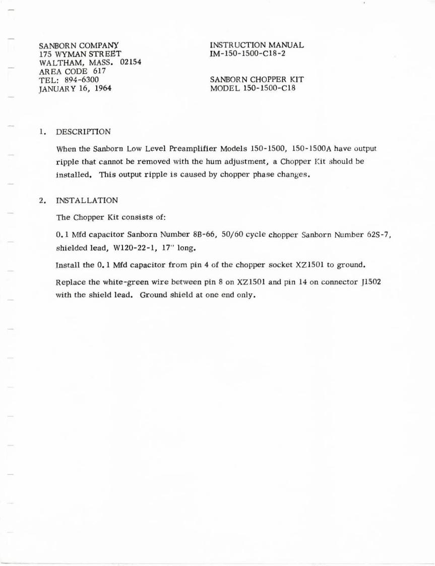
1. DESCRIPTION
INSTRUCTION MANUAL IM-150-1500-ClS-2
SANBORN CHOPPER KIT MODEL 150-1500-ClS
When the Sanborn Low Level Preamplifier Models 150-1500, 150- 1500A have output
ripple that cannot be removed with the hum adjustment, a Chopper Kit should be
installed. This output ripple is caused by chopper phase changes .
2. INSTALLATION
The Chopper Kit consists of:
0.1 Mfd capacitor Sanborn Number 88-66, 50/60 cycle chopper Sanborn Number 62S-7,
shielded lead, Wl20-22-l, 17" long.
Install the 0. 1 Mfd capacitor from pin 4 of the chopper socket XZ1501 to ground.
Replace the white-green wire between pin 8 on XZ1501 and pin 14 on connector ]1502
with the shield lead. Ground shield at one end only.


SANBORN COMPANY 175 WYMAN STREET WALTHAM 54, MASS. TEL: TW-4-6300 MAY 28, 1958
INSTRUCTION MANUAL SUPPLEJ!IENT IM-1~0-lC "' Q-lE
SANBOR~ LOW LEVEL PREAMPLIFIER MODEL 150-1500, 150-lSOOA
The signal connection shown in figure 2 of the Instruction Manual wi ll sometimes give a-c pickup with the floating input connection as s hown.
Two suggested alternate connections are shown :
THERMO-: COUPLE
SIGNAL GROUND

SANIDRN COHPANY 17 5 W)lULN STREET WALTHAM 54, MASS. TEL: TW-4- 6300 FEBRUARY 16, 1960
RPL-150- 1500-3A CR 9744 April 1, 1959
REPLACEMENT PARTS LIST SUPPLEMENTS RPL-150-1500- 3A RPL- 1)0-l ~00- 3B SANID ll!J LOW LE.V EL PREAMPLIJ:i'IER MODEL 150- 1500
Resistor Rl5S2 changed from . 1 2M 5% l/2W Composition Sanborn No. SOA- 124.J to
. lOM 5% l/2W Composit i on Sanborn Number 50AB-104J.
RPL- 150- 1500- 3B CR 10567 February 10, 1960 Schematic: 150- 1500-Cl Sub 14 (60 cycle)
150- 1500-ClPl Sub l (50 cycle)
Sanbs rn Low Level Pr eamplifier Model 150-1500 stamped with CR 10567 or higher will
nave the following changes .
Capacitor C1522 . lMID 20% 200V Mylar Sanborn Number 8B-66 is added acr oss terminals
4 and 1 of socket XZ1501.
Wir e from XZ1501-8 to Jl502- 14 is shielded and shield is connected to ground pin 1
of XZl.501.
Chopper Kl501 becomes a .9J/ ff) cycle chopper Sanborn .Number 62S- 7 .

SANBORN COMPANY 175 WYMAN STREET WALTHAM 54, MASS. TEL: TW 4-6300 MARCH 14~ 196.0
REPLACEMENT PARTS LIST SUPPLEMENT RP L-150-1500-3C
SANBORN LOW LEVEL PREAMPLIFIER MOD'C :.. JS0-1500
RPL-150-1500-3C STANDARD CHANGE CR10567 February 10, 1960
Schematic: 150-1500-Cl Sub 14
Sanborn Low Level Preamplifier stamped with CR 10567 or higher will have the following change
Add a .1 Mfd ± 203, 200V Mylar Dielectric Capacitor Cl522 from XZ1501-4 to XZlSOl-1.
The wire from Jl502-14 to XZ1501-8 is shielded.
DELETE from the parts list for the Low Level Preamplifier Model 150-1500 the fol
lowing items:
DESCRIPTION
DPDT 60 Cycle Chopper DPDT 50 Cycle Chopper DPDT 60/50 Cycle Chopper
SANBORN NO.
62S-l 62S-1A 62S-3
ADD to the parts list for the Low Level Preamplifier Model 150-1500 the following
items:
DESCRIPTION
DPDT 50/60 Cycle Chopper DPDT 60 Cycle Chopper
"Alternate for 62S-7 for 60 Cycle use" DPDT 50 Cycle Chopper
"Alternate for 62S-7 for 50 Cycle use" .1 Mfd ± 203, 200V Mylar Dielectric Capacitor
SANBORN NO.
62S-7 62S-8
62S-9
88-66

Rl501 ... ••v 1000 0.1%
I Rl502 ... 10
0.1%WW
Rl503
90· 0. 1%W\I
ZERO SUPPRESSION
~
IOTURN 0.1% LIN Rl547 200 s·~ HEUPOT
I <
: Rl548
'> T01~ww cw . • . ' Rl549 j1--: 50WW
STANDARD
! Sl404:-i
1--~ I ~
~ ~~ I ~~ "" > >o J s1so4s 8l >g ~ ~ ~ ~ -- '------1--1--~ er ~ I
'-=-1--'----i--
i ~ •. ~, I
I .~~ ! .+10!_10
: STD Sl5040 c -IOO
L- ---~---Sl.f'PRESSION RANGE
SANBORN LOW LEVEL CHOPPER MODEL 150· 1500
SCHEMATIC: 150-1500-C l SUB 12
S!~~HIJ!N ~~ CO~!,~NY CR8055 RPL-150-1500-3
---- - - - -- -- - ---- - ---- - ---- ---- - - - --- -- - - -- ,
Rl509 Rl510 Rl511 Rl512 Rl513
~o ,0c;c; l., ~<>0[01 50~
R~~~S ? --i 11 ~~: Rl507 > I '6 'l)JO .l ( R6~~ 100
0 <"0 o ~'?
~I :sao 'l.. Rl506;> Lo1ooO 1-"'-~ -~ O 100 .> 0
11----~> __ _,, ~OFF S TO<>--------' O
Sl501B~ ·t - - ~ -- - - -
L--------+------------;-- --'
0 0 0
0
0
- __/
Sl501A
. /
BTl503 1.019V
o l Rl516 v
() 50,440
0 0 .1%WW
..!... CAL 0-1200
Sl502 µV
VI 501A
Cl503 5 751
r-----<1-------~'1----+-...--+_s_sv _ __,,
.47 A. >Rl519
.-R'\.1;/\1./\7· • .l'v-+----------=2'&.Ji -~- \ 330K
IOK l Cl502A ' - I ~ .001 ~- ~
Rl51~ ._ _____ _,,_/V't/\,----4 >
c1;;04 ~--·-------,.
-:,;:- 4 70MMF
: Cl5028 .001
~ 0 +
I I
I I I
ST 1501_L STl502T
Kl502 ~,QQ~------------------------,
•
"" -.!J 7,_ \ '.> Rl520
330K ,.------------------'._ ___ Cl-5-05--'-.~rt~5SV .-----------------------i::----~V6~0-IB __ _ .47
Rl504 Rl505
I
1.3Sv
1 1.35v _
1.
100 100 1o;.ww L.._~,·~~~w!.!l..w._~ ----------------------------.
--,=~------L __
V1502 A Vl 503A Cl519 5751 Cf507 5751 ~I- II
+190V ltt\90\' ~ >5 gi . I .0022 ,47 >~
~~~ ~ : > "! N
N ~ ,_ , 2 , --- ,
~S"! ~ - " ,~ er >(\J 3 - 3
Rl530 > - A~A-AA _ gi ~ 3 30K +
> Rl524 g; -'VV\/'.cJ_ + 330K-::-
,- tt.& 71- \
O'> ~ l\.~-+ 190V N N
Cl~OS I{) ,,; (£ ~
.4 7 Vl5038
Rl527
Cl509 ...L
.0 1 I Rl531 2.2M
Rl532 • I 1000
+ Rf533:
cw 180 •
....L.
Kl 501
Cl510
I\
1~"" .22 :;; ~ a: ....
.__
:::l>6 ~~~ Cl511
Rl536 ;,•
820K
£ 1505 ......,~-+-+-+-+--+-+-+-.
,.._ > ~ ~ ~ >"'
a: >-'
V l504A 12AU7
2 - --
IN i
Rl521 v
IOOK IW
o~ s 1so3 -::- ZERO
SUPPRESSION
~ '·-I ' - V t 91V 3.---t-T--1 c11~12
~ ') "" "' ,.._ ii: ...
~ - :!, >~
o:>.,. ,-a I' +91V
~ {= I 11 =:;:--;
> "' "' +
' *'"' 1.0 "'
,.._ ir ...
~
c 1713 ~~~ ci:">"'
" 1.0
" ir ff ""tr:_
-------~ ~--~ HUM ~ Vf5048 .22
~
SENSITIVITY > 115
> g
CR71J02 Ailded pin numbers to P!L 8/30/55 CR7081 C 514, Cl515, CISl6 were 2%, oow 1% 9/16/55 CR7 109 R 536 w•s 4701(, Rl537 w•s I. SM
R 533 was 210K, Rl517, Rl518 was . 0047 9/20/55 CR7149 C 517 and C!SJ8 becomes . Olmfd ±10% 10/12/55
_lc1soss J.c1506A
I_20 :r 20
CR72J6 l:towing correction 12/5/55 CR72SI R 553 was !OK. RJ533 was 270, RIS64
CR7255 CR7320 CR7428 CR7565 CR8023 CR8055
3 ded 12/15/55 C 520 deleted 12/22/55 R 543 changed ro Rl542 1/25/56 \\ re 16 from Wll7·22· l(GR) to Wl61·20·13/29/S6 P~s 4 and 8 added to Kl SOI 7/2/56 R 572 added 4/15/57 C 506C !Omfd cllanged to Cl 506A 20mfd C 506A 20mfd changod to CJ506C IOmfd 4/23/57
Rl545 Kl5018 Kl503 NOTES:
I . DC VOLTAGES MEASURED 4700
r-1~ wrrn A DC VTVM OF
Q) 100 MEOOHMS INPUT lMPEDA.'<CE.
2. Kl503 JS A THERMAL TIME DELAY R.EU.Y. DELAY IS APPROX. 45 SECO.'<!'lS.
3. KI SOl IS A OPOT CfllPPER. Rl546 4 4. PISOI JS OONNECTOR AT TOP
·v vvv OF CHOPPER. 4700
r--Rl554 __ _ l -------1 I ·-· 1 SOK 1% ,~--~~r Cir~ 1 I I .01 1% .011% I I R 15,?~ R~5-56 I I Rl557 '> 103~SK 1%1 Kl°3.5K 1•1. > I
SOOK ;> T..l.. Cl516 • Rl558 =-Cl5l7 XZ1501 I% :J .0 33 8 5K 1% .01
- k4 ~~ Cl 18 1% 10% I <2 < '1---e.-------~ <S < Rl559 .QI I <5 < ,75M 10%
+ N
+ ------ - --1-<,8 - 1% ~ I , ~Rl560
- "' ' . ... ... 0 0 .... "' w UJ
• • Rl563
> "' " +
> I{)
" +
~1I=i ;,;I~/~· : Rf.62 I J.5M 1% I
I '> Rl57il ~ L--~ T~~L-~.!...,' .. f_3_~--v-15-=: ... 2_s_9_v_'~-~~;'-5--~--v-1-'~: ... ~:1 mw. '"j ~~~'
L_~~~~~------~~~------:--,....-~~~~~~~--------'''--~--.1 I J.f NVV\,- :~41 ~l Jo. . ' ,~-+-.J...J,1-4, ,-,-,~lt-\,+,-,--J+-J.,1--, -v--+-' V_ V_'+..::-V- 'v--1.Jf-+-v- -+->Jt-Jti--+-,,+-iii
~ SClf.17 I I _,
- - - z-TsoT - -
J 150• I 2 20 18 21 8 4 23 411 ':l 7 10 17 6 22 5 3 II 12 16 19 15 14 13

SY:MBOL DESCRIPTION SANBORN NO. VENDOR CODE
BT1501 Mercury Battery 2A-10 RM4R(MAL) BT1502 Mercury Battery 2A-10 RM4R(MAL) BT1503 Standard Cell 2C-l Mod 3, type 4, (WES)
Cl501 .01mfd400 vdcw Paper 88-37 67P(SPR) Cl502A .001 x .001 Ceramic 8E-10 29C7(SPR) Cl502B • 001 x • 001 Ceramic 8E-10 29C7(SPR) Cl503 .47 mfd 200 vdcw Paper 8B-51 620(GA) Cl503 Alternate • 4 7 mfd 200 vdcw 8B-79 62l{GA) Cl504 470 rnmf Ceramic 8E-9 HQ{AER) Cl505 • 4 7 mfd 200 vdcw Paper 8B-51 620(GA) Cl506 20 -20-10 mfd Electrolytic 572 -217 QC{CD)
*Cl507 • 4 7 mfd 200 vdcw Paper 8B-51PG 620(GA) *Cl508 • 4 7 rnf d 200 vdcw Paper 8B-51PG 620(GA) Cl509 • 01 mf d 400 vdcw Paper 8B-37 67P(SPR)
*Cl510 • 22 mfd 200 vdcw Paper 8B-52PG 62l(GA) *Cl511 • 22 mfd .200 vdcw Paper 8B-52PG 62l{GA) *Cl512 l mfd 200 vdcw Paper 8B-59PG 62l(GA) *Cl 513 1 mfd 200 vdcw Paper 8B-69PG 62l(GA) Cl514 .01 mfd 400 vdcw Paper 8B-61 62l(GA) Cl515 .01 mfd 400 vdcw Paper 8B-61 62l(GA) Cl516 • 033 mfd 400 vdcw Paper 8B-62 62l(GA) Cl517 • 01 rnfd 400 vdcw Paper 8B-37 67P(SPR) Cl518 .01 mfd 400 vdcw Paper 8B-37 67P(SPR) Cl519 • 0022 rnfd 600 vdcw Paper 8B-39 67P(SPR)
Jl501 5- Contact AN socket 10A5- 1FX 97-3102A-145-5S(AMP) Jl502 24- Contact connector 10B24-1MX 26-159-24(AMP)
Kl50 1 DPDT 60 cycle chopper 625-1 A-11 Kl502 SPOT ::elay 62R-4 41F6- 12000S-PAL(SIG) Kl503 Time delay relay 62R-3 6C45T{AMP)
Pl501 i s a connector at top of chopper
Rl SO l l K .i./10% Wire Wound 54A-47T T L3l{TEL) Rl502 10 ohm 1/103 Wire Wound 54A-48T TL3l{TEL) Rl503 90 ohm 13 Wire Wound 54A-49F TL3l{TEL) Rl504 100 ohm 13 Wire Wound 54A-51F TL3l{TEL) Rl505 100 ohm 1% Wire Wound 54A- 51F TL3l{TEL) Rl506 100 ohm 1% l/4W Composition 50H-101G C-ll(WEL) Rl507 100 ohm 1% l/4W Composition 50H-101G C-ll(WEL) Rl508 300 ohm 1$ l/4W Composition 50H-301G C-ll(WEL) Rl509 500 ohm 1% l /4W Composition 50H-501G C-ll(WEL) Rl510 1Kl% l/4W Composition 50H-102G C-ll(WEL) Rl511 3K 1% l /4W Composition 50H-302G C- ll(WEL) Rl512 SK 1% l/4W Composition 50H-502G C- l l(WEL) Rl513 lOK 1% l /4W Composition 50H-103G C-ll(WEL) Rl514 30K 1% l /4W Composition 50H-303G C- ll(WEL) Rl515 SOK 1% l/4W Composition 50H-503G C- ll(WEL) Rl516 50. 44K 1/ 10% Composition 50A -52T TL3l{TEL) Rl517 lOK 5% l /2W Composition 50A-103J EB(AB) Rl518 4. 7K 5% l/2W Composition 50A-472J EB(AB)
*Rl519 • 33M 5% l/2W Composition 50AB- 334JPG EB(AB) *Rl 520 • 33M 53 l/2W Composition 50AB-334JPG EB(AB)
Rl521 • IM 5% lW Composition 51D-104J GB(AB) *Rl522 2. 2M 5% l/2W Composition 50AB- 225JPG EB(AB) *Rl523 2. 2M 5% l/2W Composition 50AB -225JPG EB(AB) Rl524 • 33M 5% l/2W Composition 50AB-334J EB(AB)
*Rl525 • 39M 5% l/2W Composition 50A-394JPG EB(AB) *Rl526 • 39M 5% l/2W Composition 50A-394JPG EB(AB)
Rl527 47K 5% l/2W Composition 50AB-473J EB(AB)

*RI528 2. 2M 5% I/2W Composition 50AB-22SJPG EB(AB) *RIS29 2. 2M S% l/2W Composition 50AB- 225JPG EB(AB)
RI530 • 33M S% l/2W Composi tion 50AB-334J EB(AB) RI S31 2. 2M S% I/2W Composi tion 50AB-22SJ EB(AB) R1532 IK Potentiom eter S6A-IO C- 102I(AB) RI 533 IBO ohm S% I /2W Composi · n 50A-18IJ EB(AB)
*R1S34 • 39M S% 1/2W Composition 50A-394JPG EB(AB) *RI535 • 39M 5% I/2W Composition 50A-394JPG EB(AB) RIS36 • 82M S% I /2W Composition 50A-824J EB(AB) RI537 I. SM S% I/2W Composi tion 50AB-15SJ EB(AB) RIS38 I. 2M S% I/2W Composition . 50A- I25J EB(AB) RIS39 IM Potentiom eter S72-230 JLC- 10S2(AB)
*RI540 47K 5% l/2W Composition 50AB-473JPG EB(AB) *RI54 I 4 7K S% I/2W Composition SOAB-4 73JPG EB(AB)
RI542 22K S3 I/2W Com position 50A-223J EB(AB) *RI543 47K S% l/2W Composition SOAB-4 73JPG EB(AB} *R1544 47K S% I/2W Composition SOAB-4 73JPG EB(AB) *RI54S 4. 7K 53 l/2W Compos ition 50A-472JPG EB(AB) *Rl546 4. 7K S% I/2W Composition 50A-472JPG EB(AB) RI547 200 ohm Potentiometer S6C-8 1000A2(HEL) RI548 3. 8 ohm I 3 Wire Wound 54A-50F T L3I(TEL) RI549 50 ohm Wire Wound Pot. 56A-67 2W(IRC) RI SSO 99K 1/ 103 Wire Wound 54A-45T T L3l(T EL) RISS I 9K I/ 10$ Wire Wound I 54A-46T T L3l(TEL) RISS2 • 12M 53 l/2W Composition 50A - 124J EB(AB) RI553 25K Potentiometer 56A-53 C-243l(AB) Rl554 SOK I % l/4W Composition 50H-503G C- ll(WEL) RI SSS 103. SK 13 l/4W Comp. 50H-103S- 2G C-ll(WEL) RI556 I03. SK 1% I/4W Comp. I 50H- 1035-2G C-ll(WEL) RI S57 • SM 13 l/4W Composition 50H-S04G C-ll(WEL) RlS58 85K 1% l/4W Composition 50H-8S3G C- ll(WEL) RISS9 • 75M I 3 I/4W Composition 50H-754G C-ll(WEL) RI560 4. 7M 13 l /2W Composition 50J-47SG C-12(WEL) RlS61 4. 7M 13 l /2W Composi tion SOJ -47SG C-12(WEL) Rl562 1. SM 13 l / 2W Composition SOJ-15SG C-12(WEL) RlS63 S6 ohm 53 2W Composition 52C-560J HB(AB) Rl564 27K 53 l /2W Composition 50AB-273J EB(AB) RlS72 SOK 13 l/4W Composition 50H-203G C-ll(WEL)
Sl501 2-Deck, 12 pos. wafer sw. 62B-8 5360-4MLW -2(G RI) Sl 502 Aero switch 62C-3 3M03 - 1A(ACR) Sl 503 SPST toggle switch 62D-21 86510(ARR) Sl504 2 Deck, 5 pos. wafer sw. 62B- 28 Special(GRI)
TlSOl Input transformer 66B-27 W5463(UTC)
VlSOl Type S7Sl 68A-37 (GE)(RCA) Vl502 Type 5751 68A-37 {GE){RCA) Vl 503 Type 5751 68A-37 (GE)(RCA) Vl504 Type 12AU7 69A-11 Special Commer cial
Z lSOl Filter Assembly ISO~ 1500 -Cl6P I
*The following condensers are 1natched within 23 : (Cl507. Cl508), (Cl510, ClSlJl), (CIS12, Cl513).
*The following resistors are matched within 2%: (Rl 519, Rl520). (Rl522, Rl523), {Rl525, Rl526). (Rl528, Rl529). (R1534, Rl 535), (Rl540, Rl541). (Rl543, Rl544). {Rl54S, Rl546).
VENOOR ABBREVIATIONS
AB Allen Bradley ACR Aero AER Aerovox AMP Amphenol ARR Arrow-Hart & Hegeman GA Good All CD Cornell Dubilier GRI Grisby-Alliscn HEL Hell pot IRC International Resistance Co. MAL Mallory RCA Radio C.Orporation of America SIG Sigma SPR Sprague STE Stevens Arnold TEL Tel Labs UTC United Transformer c.o. WEL Welwyn WES Westinghouse