Harley Sportster · HARLEY DAVIDSON SPORTSTER 1979-2003 TRIKE CONVERSION KIT Cass County Choppers,...
14
Cass County Choppers 913.710.2225 19420 S Raffurty Road [email protected] Pleasant Hill, MO 64080 www.casscountychoppers.com Phone: 913.710.2225 Fax: 866.737.0818 Email: [email protected] PO Box 446 Pleasant Hill, MO 64080 CUSTOM TRIKE AND MOTORCYCLE PARTS Harley Sportster 1979 - 2003 Trike Conversion Kit
Transcript of Harley Sportster · HARLEY DAVIDSON SPORTSTER 1979-2003 TRIKE CONVERSION KIT Cass County Choppers,...

Cass County Choppers 913.710.2225 19420 S Raffurty Road [email protected] Pleasant Hill, MO 64080 www.casscountychoppers.com
Phone: 913.710.2225 Fax: 866.737.0818
Email: [email protected] PO Box 446
Pleasant Hill, MO 64080
CUSTOM TRIKE AND MOTORCYCLE PARTS
Harley Sportster 1979 - 2003
Trike Conversion Kit
Cass County Choppers 913.710.2225 19420 S Raffurty Road [email protected] Pleasant Hill, MO 64080 www.casscountychoppers.com
We want to thank you for your purchase of a Cass County Choppers Harley-Davidson Sportster 1979-2003 Trike Conversion
Kit.
If you have questions or comments, please feel free to email or call using the contact information at the bottom of this
page.
Cass County Choppers, LLC will not be held responsible for any damage that occurs during disassembly or reassembly. If you
are unsure about anything in the assembly process, please call or consult a qualified mechanic. We also offer the service of
converting your bike into a trike; contact our support team for details and pricing.
CONTENTS
Sales and Return Policy ........................................................................................................................................................... 3
Purchase Agreement ............................................................................................................................................................... 3
Parts List .................................................................................................................................................................................. 5
Assembly Schematic ................................................................................................................................................................ 7
Assembly Instructions.............................................................................................................................................................. 8
Assembly Pictures .................................................................................................................................................................. 13

Cass County Choppers 913.710.2225 19420 S Raffurty Road [email protected] Pleasant Hill, MO 64080 www.casscountychoppers.com
SALES AND RETURN POLICY
All sales are final. If damage has occurred during transit, contact Cass County Choppers, LLC. immediately for details on
processing a replacement. Any damage claims must be made within 5 calendar days of item receipt. No returns or
exchanges will be provided unless a Return Authorization Request has been previously approved by Cass County Choppers,
LLC. and products will be subject to a forty percent restocking fee. Any return shipping charges are the responsibility of the
purchaser. If you are shipping an item over $75, we recommend purchasing shipping insurance and/or sending with a
trackable service as we don’t guarantee receipt of your returned item. Cass County Choppers, LLC. is not responsible for
lost or stolen packages confirmed to be delivered to the address entered for an order. Upon inquiry, Cass County Choppers,
LLC. will confirm delivery to the address provided, date of delivery, tracking information and shipping carrier information
for the customer to investigate.
PURCHASE AGREEMENT
This Hold Harmless and Indemnification Agreement (“Agreement”) is entered into by and between the customer(purchaser)
hereinafter “Promisor”, and Cass County Choppers, LLC., hereinafter “Promisee”.
The intent of this Agreement is to indemnify Promisee from any claims arising from and related to the purchase, installation
and/or use of any Cass County Choppers, LLC. product(s).
FOR VALUABLE CONSIDERATION, the receipt of which is hereby acknowledged, Promisor and Promisee agree as follows:
Promisor will indemnify and hold harmless Promisee from any and all claims, actions, and judgments, including all costs of
defense and attorney’s fees incurred in defending against same, arising from and related to the purchase, installation and/or
use of any Cass County Choppers, LLC. product(s) either directly and/or indirectly. Promisor’s actions include the acts of
Promisor’s agents and employees. By examining our products online, in a brochure, at the showroom, and/or in person,
you have satisfied to your expectations to accept the product as-is and with any and all faults.
In the event any claim or suit is brought against Promisee within the scope of this Agreement, Promisor shall pay for legal
counsel chosen by Promisee to defend against the same.
This Agreement shall encompass claims resulting from any actions that many give rise to a claim against the promise
including, but not limited to:
Normal usage of the product. Normal usage defined by, but not necessarily defined in full by, a person 18 years or
older being the sole pilot of a Cass County Choppers, LLC. product, not riding on state, county, city, town or village legal
streets, roads, and/or highways in an improper manner.
Misuse of the product. Misuse is defined by, but not necessarily defined in full by, any person under the age of 18
operating a Cass County Choppers, LLC. product, and/or more than one (1) person on a Cass County Choppers, LLC.
product at any given time, and/or not operating on public streets, roads and/or highways, and/or operation on rough
surfaces and/or in dark conditions, including fog in any way, and/or not consistent with applicable laws of governing
state, and/or operation on slippery surfaces including but not limited to water, ice and/or snow covered surfaces,
and/or jumping, and/or excessive speeds, and/or excessive weight, and/or standing operation, and/or one wheel

Cass County Choppers 913.710.2225 19420 S Raffurty Road [email protected] Pleasant Hill, MO 64080 www.casscountychoppers.com
operation, and/or fueling with product other than that specified by the engine Manufacturer, and/or operation on
rough surfaces, and/or failure to maintain the product in a proper manner. Maintenance is the sole responsibility of
the Promisor, its agents and employees.
Note: Installing any Cass County Choppers, LLC. product to your bike may affect the warranty the Manufacturer provides.
Consult the manufacturer prior to installation; you accept any nullificiation of warranty by continuing with installation.
Any purchase, use, and/or installation of this product by the promisor, including its agents and employees is considered an
agreement to the terms and conditions of this agreement and shall be construed as a signature. By signing, you signify
understanding and agreement to all warnings, statements and claims presented in this document. You also signify that you
are legally able to provide signature. If you are unsure about releasing any and all claims or do not wish to proceed by using
or installing a Cass County Choppers, LLC product, STOP now and send the parts back. Please contact our support staff for
details on on return policy and procedures.
In the event either party files suit in a court of law to interpret or to enforce the terms of this Agreement, the party
prevailing in such action shall be entitled, in addition to any legal fees incurred in defending against any third party claim,
to its reasonable legal fees and costs incurred in such action to interpret or to enforce the terms of this agreement. If a
term or condition is found to be unenforceable, the rest of the agreement still remains in affect.
This agreement shall be interpreted under the laws of the State of Missouri.
Signature: ____________________________________________________________________________
Printed Name: _________________________________________ Date: __________________________
Cass County Choppers 913.710.2225 19420 S Raffurty Road [email protected] Pleasant Hill, MO 64080 www.casscountychoppers.com
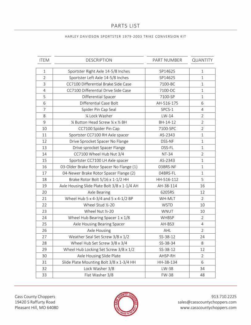
PARTS LIST
HA RLE Y D AVIDS ON SPO RTS TER 1 97 9 -2 003 TR IKE CO N VERSIO N K I T
ITEM DESCRIPTION PART NUMBER QUANTITY
1 Sportster Right Axle 14-5/8 Inches SP14625 1
2 Sportster Left Axle 14-5/8 Inches SP14625 1
3 CC7100 Differential Brake Side Case 7100-BC 1
4 CC7100 Differential Drive Side Case 7100-DC 1
5 Differential Spacer 7100-SP 1
6 Differential Case Bolt AH-516-175 6
7 Spider Pin Cap Seal SPCS-1 4
8 ¼ Lock Washer LW-14 2
9 ¼ Button Head Screw ¼ x ½ BH BH-14-12 2
10 CC7100 Spider Pin Cap 7100-SPC 2
11 Sportster CC7100 RH Axle spacer AS-2343 1
12 Drive Sprocket Spacer No Flange DSS-NF 1
13 Drive sprocket Spacer Flange DSS-FL 1
14 CC7100 Wheel Hub Nut 3/4 NT-34 2
15 Sportster CC7100 LH Axle spacer AS-2343 1
16 03-Older Brake Rotor Spacer No Flange (1) 03BRS-NF 1
17 04-Newer Brake Rotor Spacer Flange (2) 04BRS-FL 1
18 Brake Rotor Bolt 5/16 x 1-1/2 HH HH-516-112 5
19 Axle Housing Slide Plate Bolt 3/8 x 1-1/4 AH AH-38-114 16
20 Axle Bearing 6205RS 12
21 Wheel Hub 5 x 4-3/4 and 5 x 4-1/2 BP WH-MLT 2
22 Wheel Stud ½-20 WSTD 10
23 Wheel Nut ½-20 WNUT 10
24 Wheel Hub Bearing Spacer 1 x 1/8 WHBSP 2
25 Axle Housing Bearing Spacer AH-BS3 4
26 Axle Housing AHL 2
27 Weather Seal Set Screw 3/8 x 1/2 SS-38-12 24
28 Wheel Hub Set Screw 3/8 x 3/4 SS-38-34 8
29 Wheel Hub Locking Set Screw 3/8 x 1/2 SS-38-12 12
30 Axle Housing Slide Plate AHSP-RH 2
31 Slide Plate Mounting Bolt 3/8 x 1-3/4 HH HH-38-134 6
32 Lock Washer 3/8 LW-38 34
33 Flat Washer 3/8 FW-38 48

Cass County Choppers 913.710.2225 19420 S Raffurty Road [email protected] Pleasant Hill, MO 64080 www.casscountychoppers.com
ITEM DESCRIPTION PART NUMBER QUANTITY
34 Support Bar Bolt 3/8 x 1-1/2 HH HH-38-112 4
35 Lower Support Bar (Choppers/Trikes) LSB-CT 1
36 Upper Support Bar (Cass County Choppers) USB-CCC 1
37 Support Rod Bolt 3/8 x 1-1/2 HH HH-38-112 2
38 Sportster Support Rod SSR-34 1
39 Sportster Swingarm Pivot Spacer SS-PS1 2
40 Drive Sprocket Bolt 7/16 x 1-3/4 HH HH-716-134 5
41 Tensioner Bar Bolts 3/8 x 1-1/2 HH HH-38-112 4
42 Sportster Center Block SCB-01 1
43 Sportster Steel Pivot Plates SSP-PLT 2
44 Tensioner Bolt 3/8 x 3-1/2 TPHH TPHH-38-312 2
45 2003-Older Sportster Pivot Bushing SP03-IPB 1
46 Sportster Right Side Plate SRS-PLT 1
47 Sportster Shock Bolt ½ -20 x 1-1/2 HH HH-12F-112 2
48 Sportster Left Side Plate SLS-PLT 1
49 Pivot Plate Bolt 3/8 x 4 HH HH-38-4 16
50 Belt Tension Bar BTT-SPT 2
51 Exhaust Spacer ¾ x ¾ ES-34-34 1
52 Exhaust Spacer Bolt 5/16 x 1-3/4 HH HH-516-134 1
53 Exhaust Spacer Nut NT-14 1
54 Exhaust Spacer Washer ¼ Flat Washer FW-14 2
55 Exhaust Spacer Washer 5/16 Lock Washer LW-516 1
56 Outside Pivot Spacer SP03-OPS 1
58 Upper Shock Spacers 1-1/4 x 1 USS-114-1 1
59 Upper Shock Bolt ½ x 3 HH HH-12-3 1
60 Caliper Bracket Bolt 3/8 x 1-1/4 AH AH-38-114 2
61 Caliper Bracket WWCB01 1
62 Caliper Wilwood 120-7740-P 1
63 Caliper Washer 3/8 SAE FW FW-38-SAE 2
64 Caliper Mount Bolt 3/8 x 1-1/4 HH HH-38-114 2

Cass County Choppers 913.710.2225 19420 S Raffurty Road [email protected] Pleasant Hill, MO 64080 www.casscountychoppers.com
ASSEMBLY SCHEMATIC
HA RLE Y D AVIDS ON SPO R TS TER 1 97 9 -2 003 TR IK E CO N VERSIO N K IT

Cass County Choppers 913.710.2225 19420 S Raffurty Road [email protected] Pleasant Hill, MO 64080 www.casscountychoppers.com
ASSEMBLY INSTRUCTIONS
HA RLE Y D AVIDS ON SPO RTS TER 1 97 9 -2 003 TR IKE CO N VERSIO N K I T
Cass County Choppers, LLC will not be held responsible for any damage that occurs during disassembly or
reassembly. If you are unsure about anything in the assembly process please call or consult a qualified
mechanic. We also offer the service of converting your bike into a trike call for details and pricing.
ASSEMBLY TIP: Clean off a workbench and lay ALL parts out onto workbench. Place fasteners with each
corresponding part using the parts list as a guide. Some fasteners may be not bagged together with parts
in some kits for ease of shipment. Take time to measure and separate fasteners before beginning assembly
to avoid using incorrect bolts, etc. Read ENTIRE installation instruction booklet before beginning assembly.
You will gain a better understanding of the entire process and assembly time will be GREATLY reduced.
Step 1:
Secure your bike using a front wheel vise and straps. A qualified motorcycle lift is recommended.
Step 2:
Remove heat shield from exhaust if present.
Step 3:
Remove exhaust system including the Exhaust support bracket.
Step 4:
Set exhaust system aside making sure to keep all bolts, flanges, and exhaust gaskets together.
Step 5:
Break loose the rear axle nut, BUT DO NOT REMOVE AT THIS TIME. Raise the rear end of bike using a
center jack. (Bike front wheel securely in wheel vise or equivalent.)
Step 6:
Remove rear axle nut, and slide rear axle out of wheel, remove wheel, caliper, lower shock mounting
bolts, and then remove the swingarm assembly from bike. (Follow instructions in a maintenance
Manual for your model year bike.) . Leave lower shock mounting bolts in shocks. Remove splashguard.
Place swingarm pivot bolts next to bike one on each side so they are readily available when mounting
the trike conversion kit.
Step 7:
Remove the brake rotor by securing wheel and removing bolts holding brake rotor to wheel. Then
remove the sprocket from wheel, by securing the wheel and removing the bolts holding sprocket to
wheel.
Step 8: YOU WILL NEED HELP DURING THIS STEP! DO NOT ATTEMPT TO DO THESE STEPS ALONE!

Cass County Choppers 913.710.2225 19420 S Raffurty Road [email protected] Pleasant Hill, MO 64080 www.casscountychoppers.com
Lift the trike assembly out of the box and place behind the motorcycle with the swingarm pivots facing
towards the bike and brake caliper on correct side. Cut wire ties holding the swingarm pivot bushing in
the right swingarm pivot. (See Pic #1) Leave bushing in the right swingarm pivot.
Step 9:
Lift the trike conversion kit up and slide into place where original swingarm was secured to frame. Have
your helper install the swingarm pin through the left side swingarm pivot and right side swingarm pivot
bushing. Thread nut onto right hand side of swingarm pivot pin, making sure washer is in place between
pivot and nut, but do not tighten at this time.
Step 10:
While holding the trike conversion kit up in the correct position, install the left side shock using the
provided lower shock mounting bolt on the left side of trike side plate. Trike conversion should be held
in place by shock. Rest for a minute!
Step 11:
Remove the 8 – 3/8 x 4 HH bolts and 1 – 3/8 x 1-1/2 HH bolt shown in picture #2 from RIGHT SIDE
ONLY! Place them directly below trike conversion kit so they will be readily accessible. Then remove
the ¾ nut from the end of BOTH wheel hubs shown in picture #3. Place them below wheel hub. Remove
2 – 3/8 x 1-1/2 HH bolts and 2 – 3/8 x 2-1/4 HH bolts holding rear support bars in place shown in Picture
#4. Place directly below trike kit.
Step 12:
Remove right side wheel hub by pulling it from the right side differential axle. Remove left side wheel
hub in same manner. (CAUTION DO NOT LOSE WHEEL HUB BEARING SPACER THAT IS BEHIND WHEEL
HUB.) Set aside for now.
Step 13:
Pull right side plate and axle housing as an assembly from right side of trike kit. Be careful pivot plate
spacer on front of swingarm does not fall and get damaged. Set aside.
Step 14:
Remove the differential assembly by pulling out of left side axle housing. CAUTION DO NOT LOSE AXLE
BEARING SPACERS THAT ARE ON AXLES. Have your helper hold the differential and install the brake
rotor to brake side of differential using the 5/16 screws, 5/16 lock washers, flat washers, and Brake
Rotor Spacers provided on the differential. Remove 5 – 5/16 bolts and washers, CAUTION keep them
together. Slide brake rotor over axle and over flange on differential assembly. Re-install 5/16 bolts and
washers. Make sure step of Brake Rotor Washer goes into brake rotor. Once the brake rotor is installed
carefully slide the left axle of differential through the drive belt and bearings on the left axle housing
CAREFULLY! Make sure axle spacer is still on the axle BEFORE this step. BE CAREFUL not to damage
bearings in axle housing assembly. (You may need to remove the caliper assembly before performing
this step.)
Step 15:
Install the sprocket to the right side of differential using bolts provided on Differential. Install the drive
belt over sprocket while assembling on differential at this time. Torque the bolts to 54 foot pounds.
Cass County Choppers 913.710.2225 19420 S Raffurty Road [email protected] Pleasant Hill, MO 64080 www.casscountychoppers.com
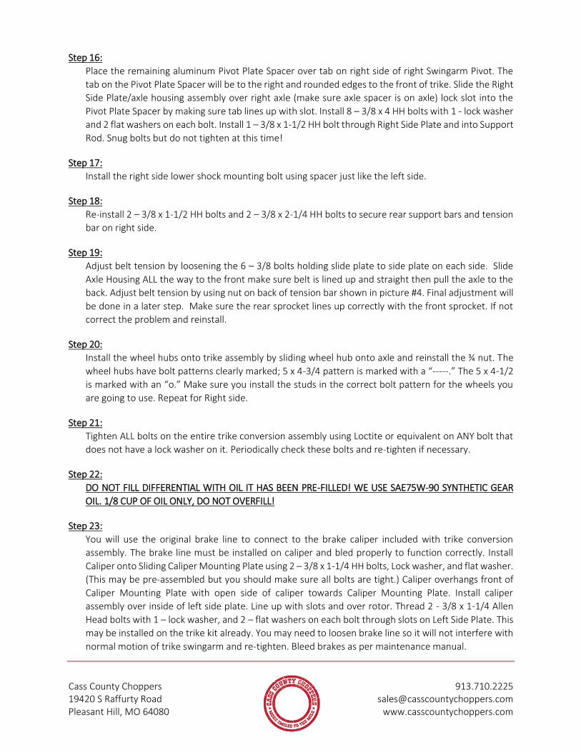
Step 16:
Place the remaining aluminum Pivot Plate Spacer over tab on right side of right Swingarm Pivot. The
tab on the Pivot Plate Spacer will be to the right and rounded edges to the front of trike. Slide the Right
Side Plate/axle housing assembly over right axle (make sure axle spacer is on axle) lock slot into the
Pivot Plate Spacer by making sure tab lines up with slot. Install 8 – 3/8 x 4 HH bolts with 1 - lock washer
and 2 flat washers on each bolt. Install 1 – 3/8 x 1-1/2 HH bolt through Right Side Plate and into Support
Rod. Snug bolts but do not tighten at this time!
Step 17:
Install the right side lower shock mounting bolt using spacer just like the left side.
Step 18:
Re-install 2 – 3/8 x 1-1/2 HH bolts and 2 – 3/8 x 2-1/4 HH bolts to secure rear support bars and tension
bar on right side.
Step 19:
Adjust belt tension by loosening the 6 – 3/8 bolts holding slide plate to side plate on each side. Slide
Axle Housing ALL the way to the front make sure belt is lined up and straight then pull the axle to the
back. Adjust belt tension by using nut on back of tension bar shown in picture #4. Final adjustment will
be done in a later step. Make sure the rear sprocket lines up correctly with the front sprocket. If not
correct the problem and reinstall.
Step 20:
Install the wheel hubs onto trike assembly by sliding wheel hub onto axle and reinstall the ¾ nut. The
wheel hubs have bolt patterns clearly marked; 5 x 4-3/4 pattern is marked with a “-----.” The 5 x 4-1/2
is marked with an “o.” Make sure you install the studs in the correct bolt pattern for the wheels you
are going to use. Repeat for Right side.
Step 21:
Tighten ALL bolts on the entire trike conversion assembly using Loctite or equivalent on ANY bolt that
does not have a lock washer on it. Periodically check these bolts and re-tighten if necessary.
Step 22:
DO NOT FILL DIFFERENTIAL WITH OIL IT HAS BEEN PRE-FILLED! WE USE SAE75W-90 SYNTHETIC GEAR
OIL. 1/8 CUP OF OIL ONLY, DO NOT OVERFILL!
Step 23:
You will use the original brake line to connect to the brake caliper included with trike conversion
assembly. The brake line must be installed on caliper and bled properly to function correctly. Install
Caliper onto Sliding Caliper Mounting Plate using 2 – 3/8 x 1-1/4 HH bolts, Lock washer, and flat washer.
(This may be pre-assembled but you should make sure all bolts are tight.) Caliper overhangs front of
Caliper Mounting Plate with open side of caliper towards Caliper Mounting Plate. Install caliper
assembly over inside of left side plate. Line up with slots and over rotor. Thread 2 - 3/8 x 1-1/4 Allen
Head bolts with 1 – lock washer, and 2 – flat washers on each bolt through slots on Left Side Plate. This
may be installed on the trike kit already. You may need to loosen brake line so it will not interfere with
normal motion of trike swingarm and re-tighten. Bleed brakes as per maintenance manual.

Cass County Choppers 913.710.2225 19420 S Raffurty Road [email protected] Pleasant Hill, MO 64080 www.casscountychoppers.com
Step 24:
Loosen the bolts holding Axle Housing Slide Plates to Side Plates. Using right side belt tensioner nut
tighten belt to desired tension. Re-Adjust the brake caliper over brake rotor making sure it is connecting
with the rotor the full amount of width on brake pads. Repeat for left side. Measure between the
tensioner mount and the axle adjustment plate on each side. These should be close to the same
dimension.
Step 25:
Tighten set screws in wheel hubs. It works best to remove all 6 locking setscrews (3/8 x ½) that are in
the top of each threaded hole in wheel hub housing and loosen but do not remove lower 6 set screws
in bottom of each threaded hole in the wheel hub housing. Tighten the ¾ inch nuts provided locking
the wheel hub to axle using Loctite. Re-tighten all 6 setscrews one at a time in bottom of each hole
securely. Then install the locking setscrew in all 6 holes using Loctite tightening each one securely. You
must use Loctite on locking setscrews ONLY. FAILURE TO INSTALL CORRECTLY CAN CAUSE INJURY OR
DEATH FROM WHEEL FAILURE. Repeat process for opposite side. Check these before riding, before each
use.
Step 26:
Install wheels and tighten to proper specs.
Step 27:
Refer to steel or fiberglass fender-mounting instructions for mounting fenders. Then send out to paint
shop of your choice. Use care when re-installing painted fenders.
Step 28:
Reinstall the exhaust system while bike is resting on wheels and tires. Use care when re-installing
exhaust system on engine. Make sure all gaskets and brackets are lined up before tightening screws.
Damage to engine can occur if not installed correctly. This is NOT covered under warranty. Use exhaust
spacer provided with bolt provided. Install the spacer on the rear exhaust bracket and then use original
screw through exhaust pipe and into threaded spacer.
ASSEMBLY NOTE: Check to see if your exhaust system interferes with the trike conversion assembly. If
it does you may need to purchase a different exhaust system. We do not guarantee that your exhaust
system will work.
Step 29:
Test bike while still on stand to make sure all steps are completed and bike is functioning properly. Spin
trike kit by hand, be careful to avoid pinch points. Rear wheels should spin freely and belt should be
straight between front and rear sprocket.
Step 30:
This instruction sheet is designed as a guide. You may need to complete additional steps not listed here.
These are not omitted on purpose but you must use common sense when installing parts on your bike.
Inspect all aspects of installation and make sure every step is completed to ensure your safety before
testing trike. Test trike slowly and close to home to make sure all steps are completed and the
installation is complete.

Cass County Choppers 913.710.2225 19420 S Raffurty Road [email protected] Pleasant Hill, MO 64080 www.casscountychoppers.com
Step 31:
Start out slowly when test-driving. Re-check tightness of screws after first use, after 100 miles and
periodically every 250 miles.
ENJOY YOUR NEW TRIKE.
Cass County Choppers 913.710.2225 19420 S Raffurty Road [email protected] Pleasant Hill, MO 64080 www.casscountychoppers.com
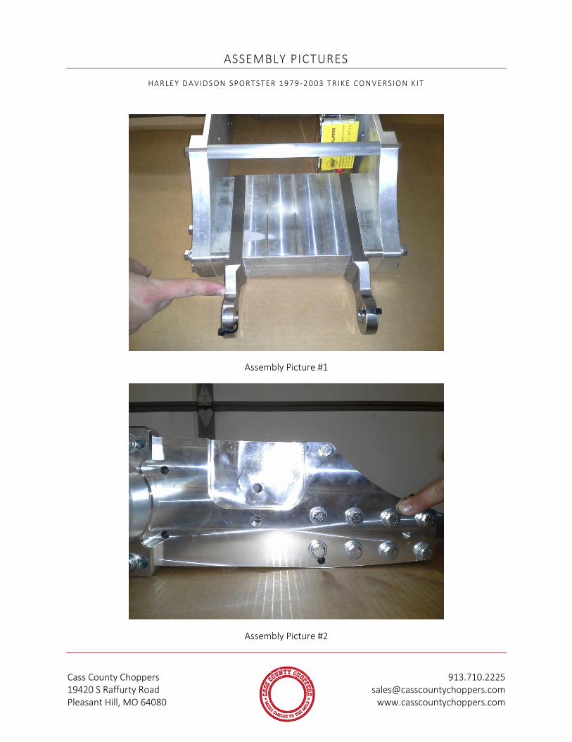
ASSEMBLY PICTURES
HA RLE Y D AVIDS ON SPO RTS TER 1 97 9 -2 003 TR IKE CO N VERSIO N K I T
Assembly Picture #1
Assembly Picture #2

Cass County Choppers 913.710.2225 19420 S Raffurty Road [email protected] Pleasant Hill, MO 64080 www.casscountychoppers.com
Assembly Picture #3
Assembly Picture #4