
Hansson Pin System Adults - Cambridge · PDF file3 Introduction The Hansson Pin system,...
20
Operative Technique Hip Fracture • Femoral Neck Fracture Hansson Pin System Adults
Transcript of Hansson Pin System Adults - Cambridge · PDF file3 Introduction The Hansson Pin system,...

Operative Technique
Hip Fracture• Femoral Neck Fracture
Hansson Pin SystemAdults

2
Introduction and Rationale 3
Relative Indications & Contraindications 4
Features & Benefits 5
Operative Technique 7
Patient Positioning
Reduction
Skin Incision and Guide Wire Insertion 8
Drilling and Measurement 9
Instrument-to-Pin Assembly 11
Insertion of the Hansson Pin and Activation of the Hook 12
Post Operative Care 13
Pin Removal 14
Ordering Information 16
Implants 16
Instruments 17
References 19
Table of Contents

3
IntroductionThe Hansson Pin system, designed by Professor Lars Ingvar Hansson at the University of Lund in Sweden, was developed based on research concerning the effects of implants on the blood supply to the femoral head.The Hansson Pin system has been designed to minimize surgical trauma to the patient and offer secure, stable fixation with reduced risk of healing complications for femoral neck fractures.Twenty years of successful clinical use have led the Hansson Pin System to its current form.
RationaleThis simple and precise procedure is used for fixation of femoral neck fracture. After reduction of the fracture, two cylindrical pins are inserted through a drilled hole and atraumatically advanced into the femoral head.After deployment of the hook, strong and stable fixation is achieved.
This publication describes a detailed recommended procedure for using Stryker Osteosynthesis devices and instruments.It offers guidance that should be followed, but, as with any such technical guide, each surgeon must consider the particular needs of each patient and make appropriate adjustments as required. A workshop training is required prior to first surgery.
Introduction and Rationale
4
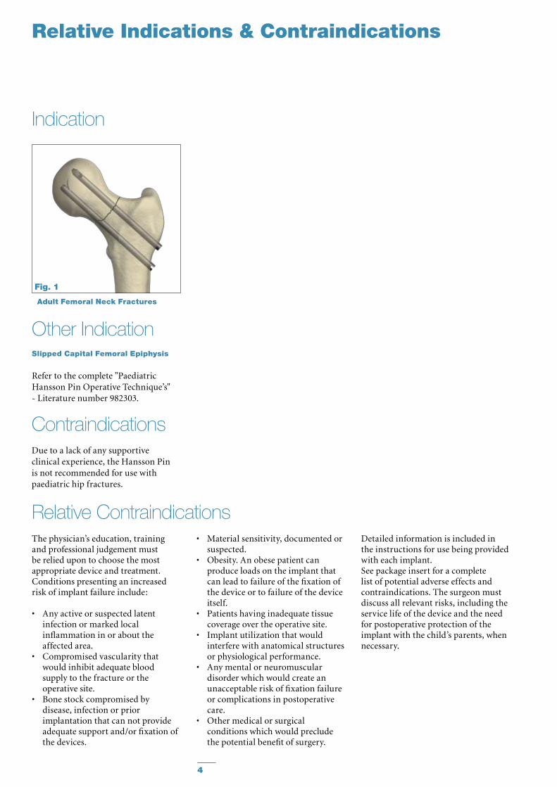
Adult Femoral Neck Fractures
The physician’s education, training and professional judgement must be relied upon to choose the most appropriate device and treatment. Conditions presenting an increased risk of implant failure include:
• Anyactiveorsuspectedlatentinfection or marked local inflammation in or about the affected area.
• Compromisedvascularitythatwould inhibit adequate blood supply to the fracture or the operative site.
• Bonestockcompromisedbydisease, infection or prior implantation that can not provide adequate support and/or fixation of the devices.
Indication
• Materialsensitivity,documentedorsuspected.
• Obesity.Anobesepatientcanproduce loads on the implant that can lead to failure of the fixation of the device or to failure of the device itself.
• Patientshavinginadequatetissuecoverage over the operative site.
• Implantutilizationthatwouldinterfere with anatomical structures or physiological performance.
• Anymentalorneuromusculardisorder which would create an unacceptable risk of fixation failure or complications in postoperative care.
• Othermedicalorsurgicalconditions which would preclude the potential benefit of surgery.
Detailed information is included in the instructions for use being provided with each implant.See package insert for a complete list of potential adverse effects and contraindications. The surgeon must discuss all relevant risks, including the service life of the device and the need for postoperative protection of the implant with the child’s parents, when necessary.
Relative Contraindications
ContraindicationsDue to a lack of any supportiveclinical experience, the Hansson Pinis not recommended for use withpaediatric hip fractures.
Other IndicationSlipped Capital Femoral Epiphysis
Refer to the complete "Paediatric Hansson Pin Operative Technique’s" - Literature number 982303.
Relative Indications & Contraindications
Fig. 1

5
Preserves bone integrity• Reduced Bone disruption.
ByusingonlytwoHanssonPinsto treat a femoral neck fracture, cancellous bone within the femoral head and neck is preserved. Furthermore, no additional fixation points are required in the femoral shaft.
Preserves the blood supply• Minimum Surgical Trauma.
The smooth profile of the Hansson Pins allows for sliding into final positioning without applying torque forces or hammering. This minimizes disruption to the blood supply and the consequent danger of avascular necrosis.6 Reduces the risks of segmental collapse and non-union.
Minimal Invasive Surgery• Small Incision.
The complete procedure is carried out through a 4-5cm incision, which can be reduced when using the Percutaneous Drill Guide.
• Short Procedure.
Simple instrumentation and a reproducible procedure allows fixation to be achieved within an adequate time frame.
Allows early mobilisation• Stable Fixation.
The security and stability of the fixation allow most patients to be mobilized during their first postoperative day and discharged early. 5
Features & Benefits
6
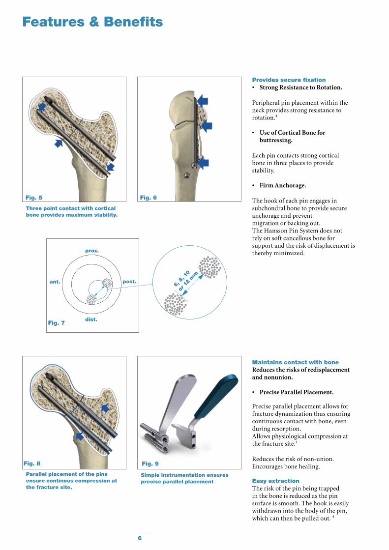
Provides secure fixation• Strong Resistance to Rotation.
Peripheral pin placement within theneck provides strong resistance torotation.4
• Use of Cortical Bone for buttressing.
Each pin contacts strong corticalbone in three places to providestability.
• Firm Anchorage.
The hook of each pin engages insubchondral bone to provide secureanchorage and preventmigration or backing out.The Hansson Pin System does notrely on soft cancellous bone forsupport and the risk of displacement isthereby minimized.
Three point contact with cortical bone provides maximum stability.
Parallel placement of the pins ensure continous compression at the fracture site.
Maintains contact with boneReduces the risks of redisplacement and nonunion.
• Precise Parallel Placement.
Precise parallel placement allows for fracture dynamization thus ensuring continuous contact with bone, even during resorption.Allows physiological compression at the fracture site.4
Reduces the risk of non-union.Encourages bone healing.
Easy extractionThe risk of the pin being trapped in the bone is reduced as the pin surface is smooth. The hook is easily withdrawn into the body of the pin, which can then be pulled out. 4
Simple instrumentation ensures precise parallel placement
Features & Benefits
6, 8
, 10
or 12
mm
Fig. 5
Fig. 8 Fig. 9
Fig. 6
prox.
dist.
post.ant.
Fig. 7
7
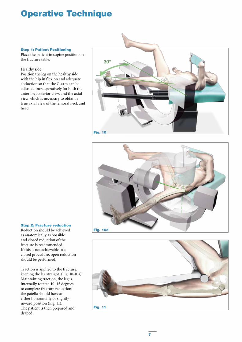
Step 1: Patient PositioningPlace the patient in supine position on the fracture table.
Healthy side:Position the leg on the healthy side with the hip in flexion and adequate abduction so that the C-arm can be adjusted intraoperatively for both the anterior/posterior view, and the axial view which is necessary to obtain a true axial view of the femoral neck and head.
Step 2: Fracture reductionReduction should be achieved as anatomically as possible and closed reduction of the fracture is recommended.If this is not achievable in a closed procedure, open reduction should be performed.
Traction is applied to the fracture, keeping the leg straight. (Fig. 10-10a).Maintaining traction, the leg is internally rotated 10–15 degrees to complete fracture reduction; the patella should have an either horizontally or slightly inward position (Fig. 11).The patient is then prepared anddraped.
Operative Technique
Fig. 10
Fig. 11
Fig. 10a

8
Step 3: IncisionIn order to find the appropriate point for limited skin incision, hold a Guide Wire over the skin surface of the hip. Angle the Guide Wire under image intensification so that it is positioned in line with the femoral neck. With the Guide Wire placed at a 135° angle, the Hansson Pin should enter the lateral cortex at the level of, but not below, the lesser trochanter.
A 10-20mm incision is made and the fascia lata is divided in the direction of the fibres.
Step 4: Distal Guide WireInsertionThe Guide Wire together with the GuideWireBushandtheProtectiveMeasuring Sleeve are inserted through soft tissues down to the lateral cortex. Starting point: • In the antero-posterior view the tip
of the Guide Wire should be at the level, but not below, the lower edge of the lesser trochanter.
• Intheaxialviewitshouldbecentralin relation to the femoral head and neck.
It is essential to have the Guide Wire close to the inner inferior cortex.
Once the alignment of the Guide Wire is satisfactory, the Guide Wire is advanced to the subchondral bone of the femoral head.
The Guide Wire Bush is then removed.
Note:To prevent unintended Guide Wire advancement and penetration in the surrounding tissue, frequently check the position of the Guide Wire under image intensification.
Note:Guide Wires are not intended for re-use. They are single use only.Guide Wires may be damaged or bent during surgical procedures.If a Guide Wire is re-used, it may become lodged in the drill and could be advanced into the pelvis, damaging large blood vessels or vital organs.
Operative Technique
Fig. 12
Fig. 13
Fig. 14

9
Step 5: Distal DrillingThe Short Cannulated Drill is inserted over the Guide Wire.The Protective Measuring Sleeve is maintained against the lateral cortex and drilling is carried out, using image intensification to ensure that the Short Cannulated Drill follows the line of the Guide Wire accurately and does not cut through the calcar. It is also important to ensure that the Guide Wire does not penetrate the hip joint. When the tip of the Short Cannulated Drill has reached the subchondral bone, the required Hansson Pin length is read off the scale on the Short Cannulated Drill protruding from the Protective Measuring Sleeve.
Note:Make sure that the Protective Measuring Sleeve is in contact with the bone when reading the scale.
The Protective Measuring Sleeve and the Guide Wire are then removed.
Operative Technique
Fig. 15
Fig. 16

10
Step 6: Proximal DrillingThe next step is to drill a hole for the proximal Hansson Pin position as close as possible to the posterior cortex of the femoral neck. This is achieved by selecting the Drill Guide (6, 8 or 10mm) which gives the widest possible separation of the pins without cutting through the posterior and superior cortex. The incision is extended 20 to 30mm, when using a Drill Guide with Elastosil Handle. The selected Drill Guide (6,8 or 10mm) is then pushed over the Short Cannulated Drill located distally and rotated, in order that the new channel is situated posteriorly and proximally to the Short Cannulated Drill located distally. In order to decrease potential risk of cutting through the posterior and superior cortex, it is possible to glide the Long GuideWireBushintotheDrillGuideand then advance a Guide Wire into the femoral Head. Thus the exact positioning can be checked before drilling, either with the Long Cannulated Drill (or with the Long Solid Drill after removing the Guide Wire).The tip of the Drill Guide is pushed into the cortex to enhance stability. The Long Cannulated Drill (or the Long Solid Drill if the Guide Wire was removed), is used to prepare the second hole, using image intensification in both AP and axial views to ensure that the Long Cannulated Drill (or the Long Solid Drill) does not cut through the posterior cortex. The hole is drilled up to the subchondral bone of the femoral head. The lateral view alone indicates whether the Long Cannulated Drill (or the Long Solid Drill) is advanced sufficiently in the femoral head. The required Hansson Pin length is again read off the scale on the Long Cannulated Drill (or the Long Solid Drill) protruding from the Drill Guide. The Long Cannulated Drill (or the Long Solid Drill) and the Drill Guide are then removed to allow for proximal Hansson Pin insertion.Note:The Hansson Pin length may be read more accurately off the Protective Measurement Sleeve, if the tip of the Drill Guide is properly anchored in the bone.
Operative Technique
Fig. 17
Fig. 19
Fig. 18

11
Step 7: Instrument-to-Pin Assembly Verify that the Inner Pin does not protrude from the window of the OuterBodyandisincorrectposition(Fig. 20).Pass the Inner Introducer through the Outer Introducer and screw it into the Hansson Pin (Fig. 23).There are unequal tabs on the Outer Introducer which correspond with slots in the Hansson Pin; the tabs and slots should securely mate when the Introducer Assembly is screwed onto the Hansson Pin. The handles of the Inner and Outer Introducers does not need to be aligned. There is a guide line on the Outer Introducer, in line with the window of the pin, indicating the direction in which the hook will be deployed.
Hansson Pin Outer Introducer Inner Introducer
Note:Do not excessively tighten the inner introducer, in order to facilitates further disassambly.
Outer BodyInner Pin
Fig. 20
Fig. 21
Fig. 22
Fig. 23
Fig. 24
Operative Technique
12
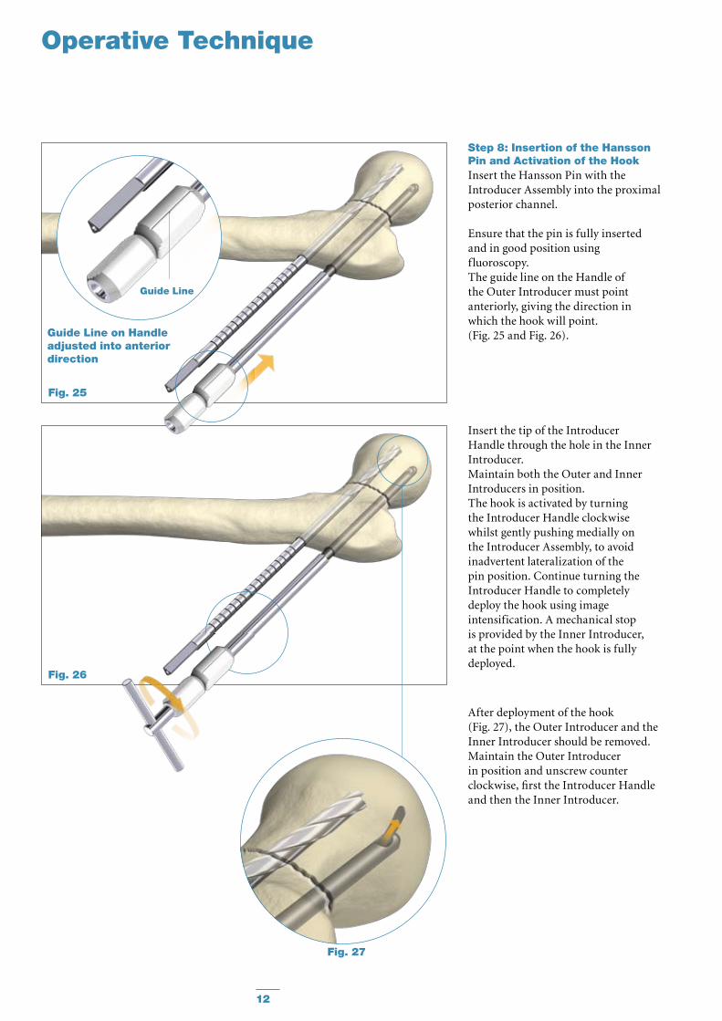
Guide Line
Step 8: Insertion of the Hansson Pin and Activation of the HookInsert the Hansson Pin with the Introducer Assembly into the proximal posterior channel.
Ensure that the pin is fully inserted and in good position using fluoroscopy. The guide line on the Handle of the Outer Introducer must point anteriorly, giving the direction in which the hook will point.(Fig. 25 and Fig. 26).
Operative Technique
Insert the tip of the Introducer Handle through the hole in the Inner Introducer.Maintain both the Outer and Inner Introducers in position.The hook is activated by turning the Introducer Handle clockwise whilst gently pushing medially on the Introducer Assembly, to avoid inadvertent lateralization of the pin position. Continue turning the Introducer Handle to completely deploy the hook using image intensification. A mechanical stop is provided by the Inner Introducer, at the point when the hook is fully deployed.
After deployment of the hook (Fig. 27), the Outer Introducer and the Inner Introducer should be removed. Maintain the Outer Introducer in position and unscrew counter clockwise, first the Introducer Handle and then the Inner Introducer.
Fig. 27
Fig. 26
Fig. 25
Guide Line on Handle adjusted into anterior direction
13
Guide Line
Operative Technique
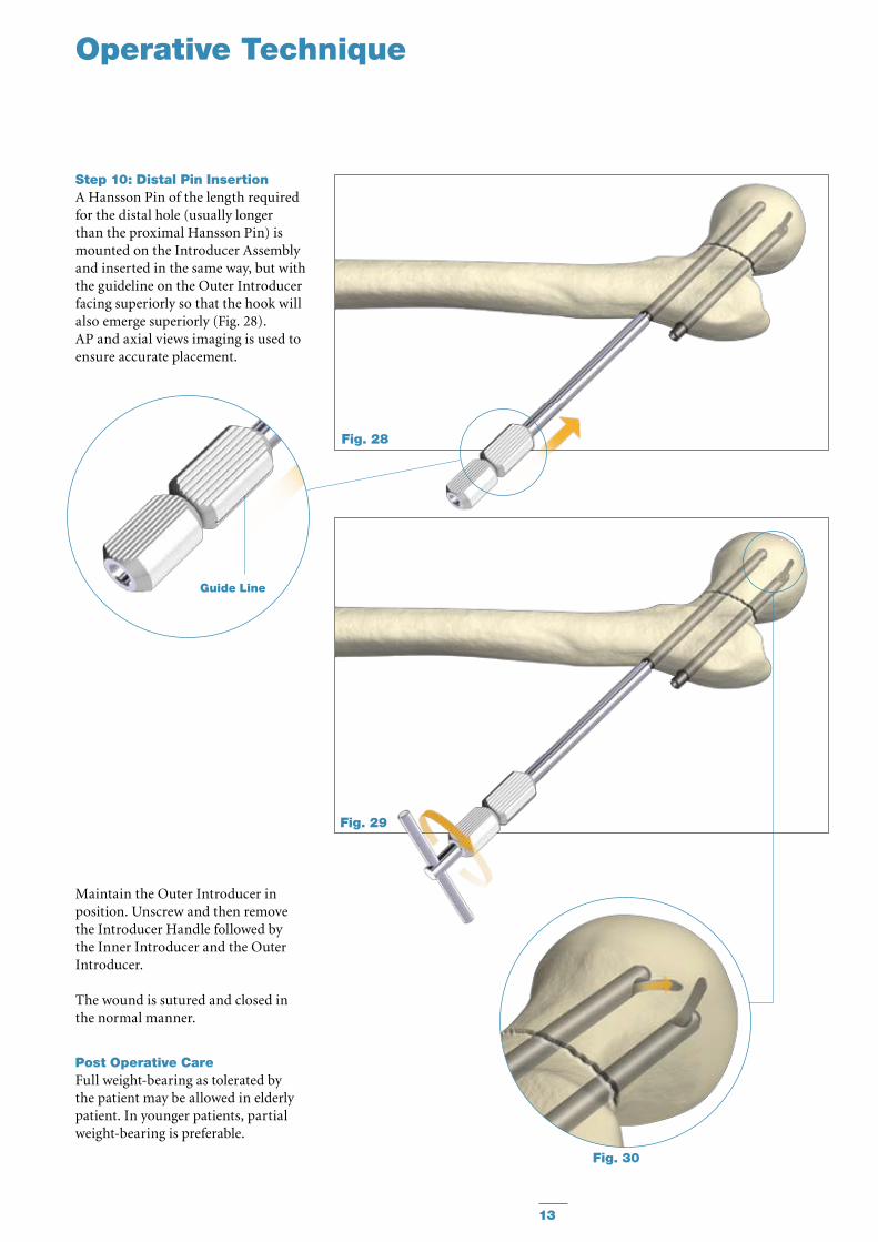
Step 10: Distal Pin InsertionA Hansson Pin of the length required for the distal hole (usually longer than the proximal Hansson Pin) is mounted on the Introducer Assembly and inserted in the same way, but with the guideline on the Outer Introducer facing superiorly so that the hook will also emerge superiorly (Fig. 28).AP and axial views imaging is used to ensure accurate placement.
Maintain the Outer Introducer in position. Unscrew and then remove the Introducer Handle followed by the Inner Introducer and the Outer Introducer.
The wound is sutured and closed in the normal manner.
Post Operative CareFull weight-bearing as tolerated by the patient may be allowed in elderly patient. In younger patients, partial weight-bearing is preferable.
Fig. 28
Fig. 29
Fig. 30
14
Engage Inner Extractor with Inner Pin
Insert and turn Extractor Handle
Key Outer Extractor over Inner Extractor
Operative Technique
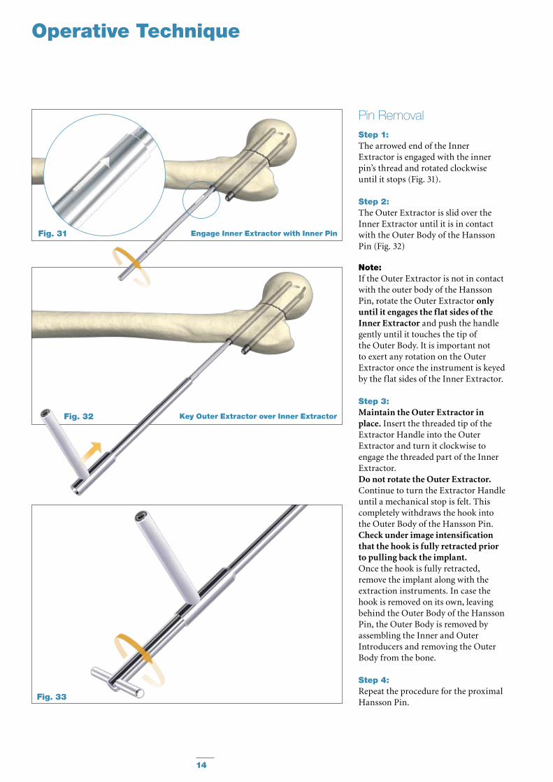
Step 1: The arrowed end of the Inner Extractor is engaged with the inner pin’s thread and rotated clockwise until it stops (Fig. 31).
Step 2: The Outer Extractor is slid over the Inner Extractor until it is in contact withtheOuterBodyoftheHanssonPin (Fig. 32)
Note: If the Outer Extractor is not in contact with the outer body of the Hansson Pin, rotate the Outer Extractor only until it engages the flat sides of the Inner Extractor and push the handle gently until it touches the tip of theOuterBody.Itisimportantnotto exert any rotation on the Outer Extractor once the instrument is keyed by the flat sides of the Inner Extractor.
Step 3: Maintain the Outer Extractor in place. Insert the threaded tip of the Extractor Handle into the Outer Extractor and turn it clockwise to engage the threaded part of the Inner Extractor. Do not rotate the Outer Extractor. Continue to turn the Extractor Handle until a mechanical stop is felt. This completely withdraws the hook into theOuterBodyoftheHanssonPin.Check under image intensification that the hook is fully retracted prior to pulling back the implant. Once the hook is fully retracted, remove the implant along with the extraction instruments. In case the hook is removed on its own, leaving behindtheOuterBodyoftheHanssonPin,theOuterBodyisremovedbyassembling the Inner and Outer Introducers and removing the Outer Bodyfromthebone.
Step 4: Repeat the procedure for the proximal Hansson Pin.
Pin Removal
Fig. 31
Fig. 32
Fig. 33

15
Notes

16
Stainless Steel Pin Titanium Ref Length Ref mm
Hansson Pins
Ordering Information – Implants
Special Order
394070S 70mm 694070S
394075S 75mm 694075S
394080S 80mm 694080S
394085S 85mm 694085S
394090S 90mm 694090S
394095S 95mm 694095S
394100S 100mm 694100S
394105S 105mm 694105S
394110S 110mm 694110S
394115S 115mm 694115S
394120S 120mm 694120S
394125S 125mm 694125S
394130S 130mm 694130S
394135S 135mm 694135S
394140S 140mm 694140S
17
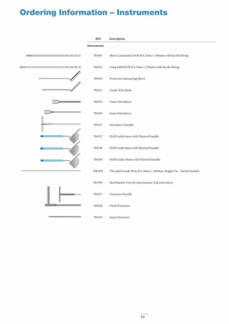
704501
704522
704510
704511
704535
704536
704517
704537
704538
704539
704505S
901704
704527
704528
704529
Short Cannulated Drill Ø 6.7mm × 246mm with Jacobs fitting
Long Solid Drill Ø 6.7mm × 276mm with Jacobs fitting
Protective Measuring Sleeve
GuideWireBush
Outer Introducer
Inner Introducer
Introducer Handle
Drill Guide 6mm with Elastosil handle
Drill Guide 8mm with Elastosil handle
Drill Guide 10mm with Elastosil handle
Threaded Guide Wire Ø 2.4mm × 300mm (Single Use - Sterile Packed)
Sterilisation Tray for Instruments (Lid and Insert)
Extractor Handle
Outer Extractor
Inner Extractor
REF Description
Instruments
Ordering Information – Instruments
18
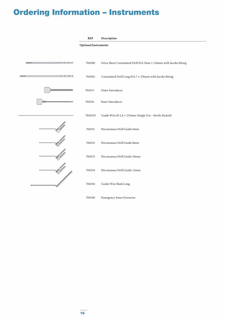
Ordering Information – Instruments
REF Description
Optional Instruments
704500 Extra Short Cannulated Drill Ø 6.7mm × 216mm with Jacobs fitting
704502 Cannulated Drill Long Ø 6.7 × 276mm with Jacobs fitting
704515 Outer Introducer
704516 Inner Introducer
704525S Guide Wire Ø 2,4 × 235mm (Single Use - Sterile Packed)
704531 Percutaneus Drill Guide 6mm
704532 Percutaneus Drill Guide 8mm
704533 Percutaneus Drill Guide 10mm
704534 Percutaneus Drill Guide 12mm
704526 GuideWireBushLong
704540 Emergency Inner Extractor
19
References
References:
1. A randomised study in all cervical hip fractures. Osteosynthesis with Hansson hook-pins versus AO-screws in 199 consecutive patients followed for two years. Mjorud J., Skaro O., Solhaug J.H., et Al.
Injury 2006; 37:768-777
2. Treatment of femoral neck fracture with Hansson Pins. A biomechanical study.
Uta S., Inoue Y., Kaneko K., Mogami A., Tobe M., Maeda M., Iwase H., Obayashi O.
JapanClinicalBiomechanics2000;21:377-383
3. Femoral neck fracture fixation with hook-pins. 2-year results and learning curve in 626 prospective cases.
StrömqvistB.,NilssonL.T.,ThorngrenK.G. Acta Orthop. Scand. 1992; 63(3):282−7.
4. The displaced femoral fracture. BrayT.J.,Smith-HoefferB.,HooperA., Timmerman L.(1988).
Clin. Orthop. 230: 127-140
5.StrömqvistB.,HanssonL.I.,NilssonL.T., and Thorngren K.G. (1987):
Hook-Pin Fixation in femoral neck fractures. A two year follow-up study of 300 cases. Clin. Orthop. 218: 58-62
6. Femoral head vitality in femoral neck fracture after hook-pin internal fixation.
StrömqvistB.,HanssonLI Clin Orthop 1984 Dec:(191):105-9
Femoral Neck Fractures

Biologics
Surgical Products
Neuro & ENT
Trauma, Extremities & Deformities
Biologics
Surgical Products
Neuro & ENT
Trauma, Extremities & Deformities
Stryker Trauma AGBohnackerweg1CH-2545 SelzachSwitzerland
www.osteosynthesis.stryker.com
The information presented in this brochure is intended to demonstrate a Stryker product. Always refer to the package insert, product label and/or user instructions before using any Stryker product. Surgeons must always rely on their own clinical judgment when deciding which products and techniques to use with their patients. Products may not be available in all markets. Product availability is subject to the regulatory or medical practices that govern individual markets. Please contact your Stryker representative if you have questions about the availability of Stryker products in your area.
Stryker Corporation or its subsidiary owns the registered trademark: Stryker.SwemacOrthopaedicsABownsthefollowingtrademark:HanssonPin.
LiteratureNumber:982338LOT A0508
US Patents pending
Copyright © 2008 Stryker


