HALFEN HSD SHEAR DOWEL SYSTEM HSD 08-E · 2 HALFEN HSD SHEAR DOWEL SYSTEM Introduction Problems...
20
HALFEN HSD SHEAR DOWEL SYSTEM CONCRETE HSD 08-E Acc. to DIN 1045-1 Officially approved Z-15.7 - 253
Transcript of HALFEN HSD SHEAR DOWEL SYSTEM HSD 08-E · 2 HALFEN HSD SHEAR DOWEL SYSTEM Introduction Problems...

HALFEN HSD SHEAR DOWEL SYSTEM
CONCRETE
HSD 08-E
Acc. to DIN 1045-1
Officially approvedZ-15.7 - 253
2
HALFEN HSD SHEAR DOWEL SYSTEM
Introduction
Problems with conventional solutions
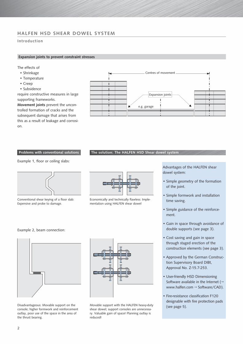
The effects ofShrinkage• Temperature• Creep• Subsidence•
require constructive measures in large supporting frameworks.Movement joints prevent the uncon-trolled formation of cracks and the subsequent damage that arises from this as a result of leakage and corrosi-on.
Centres of movement
Expansion joints
e.g. garage
Conventional shear keying of a floor slab: Expensive and probe to damage.
Disadvantageous: Movable support on the console; higher formwork and reinforcement outlay, poor use of the space in the area of the thrust bearing.
The solution: The HALFEN HSD Shear dowel system
Example 1, floor or ceiling slabs:
Example 2, beam connection:
Economically and technically flawless: Imple-mentation using HALFEN shear dowel
Movable support with the HALFEN heavy-duty shear dowel; support consoles are unnecessa-ry. Valuable gain of space! Planning outlay is reduced!
Expansion joints to prevent constraint stresses
Advantages of the HALFEN shear dowel system:
Simple geometry of the formation • of the joint.
Simple formwork and installation • time saving.
Simple guidance of the reinforce-• ment.
Gain in space through avoidance of • double supports (see page 3).
Cost saving and gain in space • through staged erection of the construction elements (see page 3).
Approved by the German Construc-• tion Supervisory Board DIBt, Approval No. Z-15.7-253.
User-friendly HSD Dimensioning • Software available in the Internet (→ www.halfen.com → Software/CAD).
Fire-resistance classification F120 • designable with fire protection pads(see page 5).

3
Construction phases:
HALFEN HSD SHEAR DOWEL SYSTEM
Application
Conventional joint design
Flat slab (vertical section)
Slab connection with console (vertical section)
Double column replaced by a single column (vertical section)
Connection of a supporting wall (horizontal section)
Expansion joint in floor slab (vertical section)
Connection between beam / support (vertical section)
Following the first concrete work section, the formwork is set and the HSD-CRET dowel element is positi-oned.
Final state of construction element using the HALFEN HSD shear dowel.
a) Application area for HALFEN CRET heavy-duty shear dowels → see pages 6 - 13.
Joints with HALFEN shear dowel
b) Application area for HALFEN single shear dowels → see pages 14 - 18
Expansion joint with HALFEN single shear do-wel between 2 freely projecting balcony slabs (top view)
Dowelling at the support of a pre-cast reinforced concrete beam on a console.balcony balcony
load-bearing structure

4
HALFEN HSD SHEAR DOWEL SYSTEM
Dimensioning
Expansion joints to prevent constraint stresses
For flat slabs, it is advisable to arran-ge the dowels at different spacings according to the different shear load concentrations. The value and the distribution of the shear load to be transmitted can be determined by an finite elements slab calculation. The static model of a continuous beam is suitable for the dimensioning of the edge of the slab. Shear and bending moments will be used for the dimensioning of the reinforcement across and along the edge. It must thereby be noted that, as a result of the proof of the punching shear load capacity, transverse and longitudinal reinforcement is also required in the load introduction area of the dowel, which could be decisive against those from the continuous beam calculation. With large dowel spacings, the con-tinuous beam calculation is normally the decisive value for the longitudinal reinforcement.
Arrangement of the shear dowel - Examples
Angled joint run
Flat slab joint; dowel arrangement corresponding to the support model for the slab
Dowel arrangement
Shear load line V
Moment line M
Load g + q
1st Concreting section
2nd Concreting section
HSD
HSD-. .V
Directionof shift
Dimensioning of the joint width ff = calculated joint width + safety supplement (approx. 1cm)
Joint
2
1
2
1
2
HSD
Joint
1 Closer spacing in the area of the support strips,
2 Larger spacing in the field strips
Shifting direction of the shear dowels:
HSD = longitudinal movement
HSD-. .V = longitudinal and transverse movement

5
A-2
53-0
3/07
122124
128134
140
für forHSD-
HALFENSchubdorn HSD
HALFENHSD
Shear Dowel20
2225
30
Brandschutzmanschette F90Fire Protection Pad F90
t=20mmt=30mm
-V
b
h
d
Ø
122124
128134
140
für forHSD-
HALFENSchubdorn HSD
HALFENHSD
Shear Dowel
A-2
53-0
3/07
2022
2530
Brandschutzmanschette F90Fire Protection Pad F90
t=20mmt=30mm
-V
b
h
d
j
i
f
AA
Fire protection pad selection
matching the HALFEN HSD shear dowel -
Item name h / b Ø or i jd = 20 ⇒ f ≤ 30d = 30 ⇒ f ≤ 40
Heavy-duty dowel, longitudinal movementCRET 122 HSD-F-CRET 122 - d 120 / 120 23CRET 124 HSD-F-CRET 124 - d 130 / 130 25CRET 128 HSD-F-CRET 128 - d 140 / 140 29CRET 134 HSD-F-CRET 134 - d 160 / 180 35CRET 140 HSD-F-CRET 140 - d 180 / 220 41Single dowel, longitudinal movement
Set 20 HSD-F 20 - d 110 / 110 21Set 22 HSD-F 22 - d 110 / 110 23Set 25 HSD-F 25 - d 110 / 110 26Set 30 HSD-F 30 - d 110 / 110 31
Heavy-duty dowel, longitudinal and transverse movementCRET-122 V HSD-F-CRET 122 V - d 120 / 120 23 46CRET-124 V HSD-F-CRET 124 V - d 130 / 130 25 50CRET-128 V HSD-F-CRET 128 V - d 140 / 140 29 58CRET-134 V HSD-F-CRET 134 V - d 160 / 180 35 70CRET-140 V HSD-F-CRET 140 V - d 180 / 220 41 82Single dowel, longitudinal and transverse movement
Set 20 V HSD-F 20 V - d 110 / 160 21 42Set 22 V HSD-F 22 V - d 110 / 160 23 46Set 25 V HSD-F 25 V - d 110 / 160 26 52Set 30 V HSD-F 30 V - d 110 / 160 31 62
HALFEN HSD SHEAR DOWEL SYSTEM
Fire protection
HSD-F fire protection pad
Ordering example:
Fire protection padMatching dowel typeThickness d [mm]
HSD-F - CRET 124 V - 30
If fire-protection is required for components according to DIN 4102 T.2, we recommend to install the HALFEN HSD shear dowels with fire protection pads. The fire protection pad can be supplied 20 mm (d = 20) and 30 mm (d = 30) thick. For larger joint widths, a combination of fire protection pads is possible.The Fire-resistance classification F120 (longitudinal movement) or F90 (longitudinal and transverse movement) is confirmed by the MFPA Leipzig.
≤ 10
f
d
[mm]Installation of HALFEN HSD-F fire protection pad
Note: The HSD-F fire protection pad consists of a material that will produce foam in case of a fire and will tightly seal the joint.
Joint plate (by contractor)
HALFEN fire protection pad
HALFEN Shear dowel 20 or 30
HSD - F - CRETHSD - Ffor shear dowels HSD,longitudinal movement
HSD - F - CRET VHSD - F Vfor shear dowels HSD, longitudinal and transverse movement
For requirements -enclosure of space- ac-cording DIN EN 1366-4 in combination with DIN EN 1363-1, we recommend to use the joint element PROMASEAL-PL (see fig.).For the combination of HALFEN shear dowel with PROMASEAL-PL the enclosing design function and the fire-resistance clas-sification F90 is confirmed by the MFPA Leipzig.
PROMASEAL-Silicone
h=sl
ab t
hick
ness
a=do
wel
spa
cing
PROMASEAL-PL-Joint element
PROMAT-Adhesive
HSD-CRET-Socket
HSD-CRET-Dowel
Mineral rock wool stripe,non-inflammable
6
HALFEN HSD SHEAR DOWEL SYSTEM
Heavy-duty shear dowels
Product description
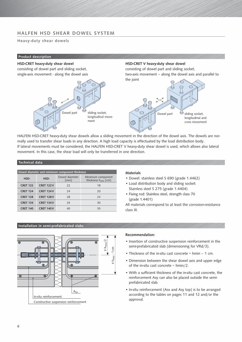
HSD-CRET heavy-duty shear dowel consisting of dowel part and sliding socket, single-axis movement - along the dowel axis
HSD-CRET V heavy-duty shear dowel consisting of dowel part and sliding socket, two-axis movement – along the dowel axis and parallel to the joint
HALFEN HSD-CRET heavy-duty shear dowels allow a sliding movement in the direction of the dowel axis. The dowels are nor-mally used to transfer shear loads in any direction. A high load capacity is effectuated by the load distribution body. If lateral movements must be considered, the HALFEN HSD-CRET V heavy-duty shear dowel is used, which allows also lateral movement. In this case, the shear load will only be transferred in one direction.
Technical data
MaterialsDowel: stainless steel S 690 (grade 1.4462)• Load distribution body and sliding socket: • Stainless steel S 275 (grade 1.4404)Fixing rod: Stainless steel, strength class 70 • (grade 1.4401)
All materials correspond to at least the corrosion-resistance class III.
Installation in semi-prefabricated slabs
Recommendation:
Insertion of constructive suspension reinforcement in the • semi-prefabricated slab (dimensioning for VRd/3).
Thickness of the in-situ cast concrete = hmin – 1 cm. •
Dimension between the shear dowel axis and upper edge • of the in-situ cast concrete = hmin/2.
With a sufficient thickness of the in-situ cast concrete, the • reinforcement Asy can also be placed outside the semi-prefabricated slab.
In-situ reinforcement (Asx and Asy top) is to be arranged • according to the tables on pages 11 and 12 and/or the approval.
Dowel diameter and minimum component thickness
HSD- HSD- Dowel diameter[mm]
Minimum component thickness hmin [cm]
CRET 122 CRET 122 V 22 18
CRET 124 CRET 124 V 24 20
CRET 128 CRET 128 V 28 24
CRET 134 CRET 134 V 34 30
CRET 140 CRET 140 V 40 35
Asy
≥ h m
in/2
≥ h m
in -
1 cm
In-situ reinforcement
Constructive suspension reinforcement
Dowel part sliding socket,longitudinal move-ment
Dowel part sliding socket, longitudinal and cross movement

7
aa
PP
bbcc
ff gg Ø
Ø
ee
ee
e
q
f
Ø
bc
KP
a
e
g
e
e bc
SP
a
fg o
Dimensions [mm]
HSD-CRET 122HSD-CRET 122 V
HSD-CRET 124HSD-CRET 124 V
HSD-CRET 128HSD-CRET 128 V
HSD-CRET 134HSD-CRET 134 V
HSD-CRET 140HSD-CRET 140 V
Dowel part Socket Socket V Dowel part Socket Socket V Dowel part Socket Socket V Dowel part Socket Socket V Dowel part Socket Socket V
a 302 180 181,5 341 192 193,5 388 215 217 450 246 248 520 280 281,5
b 180 72 73,5 192 59 60,5 215 60 62 246 66 68 280 70 71,5
c 108 108 108 133 133 133 155 155 155 180 180 180 210 210 210
d 14 — — 16 — — 18 — — 24 — — 30 — —
e 70 100 125 76 106 133 88 118 146 106 136 168 124 154 190
f 80 80 80 90 90 90 110 110 110 160 160 160 200 200 200
g 140 140 140 160 160 160 200 200 200 260 260 260 310 310 310
Ø 22 25,4 — 24 28 — 28 32 — 34 38 — 40 44 —
o — — 26 — — 28 — — 32 — — 38 — — 44
q — — 50 — — 55 — — 60 — — 70 — — 75
HSD-CRET 124 V
HALFEN HSD SHEAR DOWEL SYSTEM
Heavy-duty shear dowels
Type selection
Sliding socketSliding in longitudinal -direction
Load distribution body
Dowel part
P = Spot weldingP = Spot weldingK = PE pipe protection capK = PE pipe protection capS = Sheet metal coverS = Sheet metal cover
Sliding socket VSliding in longitudi- -nal and transverse direction
Load distribution body
Load distribution body
Ordering example:
HALFEN heavy-duty shear dowelLoad rangeV = Transverse and longitudinal movement

8
Relevant dimensioning resistances VRd [kN] HSD-CRET shear dowels with longitudinal movement
C20/25 C30/37 C40/50
Shear dowel
Com-ponent
thickness[mm]
Joint width [mm] Joint width [mm] Joint width [mm]
20 30 40 50 60 20 30 40 50 60 20 30 40 50 60
HSD- CRET 122
180 45.0 45.0 45.0 40.1 33.4 55.8 55.8 50.1 40.1 33.4 65.1 65.1 50.1 40.1 33.4
200 61.9 61.9 50.1 40.1 33.4 76.8 66.4 50.1 40.1 33.4 85.6 66.4 50.1 40.1 33.4
220 79.2 66.4 50.1 40.1 33.4 85.6 66.4 50.1 40.1 33.4 85.6 66.4 50.1 40.1 33.4
240 85.6 66.4 50.1 40.1 33.4 85.6 66.4 50.1 40.1 33.4 85.6 66.4 50.1 40.1 33.4
250 85.6 66.4 50.1 40.1 33.4 85.6 66.4 50.1 40.1 33.4 85.6 66.4 50.1 40.1 33.4
HSD- CRET 124
200 62.0 62.0 62.0 52.0 43.4 77.0 77.0 65.0 52.0 43.4 89.7 84.8 65.0 52.0 43.4
220 79.4 79.4 65.0 52.0 43.4 98.2 84.8 65.0 52.0 43.4 105.7 84.8 65.0 52.0 43.4
240 95.4 84.8 65.0 52.0 43.4 105.7 84.8 65.0 52.0 43.4 105.7 84.8 65.0 52.0 43.4
250 99.1 84.8 65.0 52.0 43.4 105.7 84.8 65.0 52.0 43.4 105.7 84.8 65.0 52.0 43.4
260 105.7 84.8 65.0 52.0 43.4 105.7 84.8 65.0 52.0 43.4 105.7 84.8 65.0 52.0 43.4
280 105.7 84.8 65.0 52.0 43.4 105.7 84.8 65.0 52.0 43.4 105.7 84.8 65.0 52.0 43.4
HSD- CRET 128
240 98.8 98.8 98.8 82.6 68.8 123.1 123.1 103.2 82.6 68.8 144.0 127.6 103.2 82.6 68.8
250 120.8 120.8 103.2 82.6 68.8 149.9 127.6 103.2 82.6 68.8 151.9 127.6 103.2 82.6 68.8
260 125.0 125.0 103.2 82.6 68.8 151.9 127.6 103.2 82.6 68.8 151.9 127.6 103.2 82.6 68.8
280 133.4 127.6 103.2 82.6 68.8 151.9 127.6 103.2 82.6 68.8 151.9 127.6 103.2 82.6 68.8
300 144.0 127.6 103.2 82.6 68.8 151.9 127.6 103.2 82.6 68.8 151.9 127.6 103.2 82.6 68.8
320 145.3 127.6 103.2 82.6 68.8 151.9 127.6 103.2 82.6 68.8 151.9 127.6 103.2 82.6 68.8
340 151.9 127.6 103.2 82.6 68.8 151.9 127.6 103.2 82.6 68.8 151.9 127.6 103.2 82.6 68.8
HSD- CRET 134
300 184.5 184.5 177.5 147.9 123.3 226.8 207.1 177.5 147.9 123.3 236.7 207.1 177.5 147.9 123.3
320 187.3 187.3 177.5 147.9 123.3 234.5 207.1 177.5 147.9 123.3 236.7 207.1 177.5 147.9 123.3
340 198.3 198.3 177.5 147.9 123.3 236.7 207.1 177.5 147.9 123.3 236.7 207.1 177.5 147.9 123.3
350 203.8 203.8 177.5 147.9 123.3 236.7 207.1 177.5 147.9 123.3 236.7 207.1 177.5 147.9 123.3
360 209.2 207.1 177.5 147.9 123.3 236.7 207.1 177.5 147.9 123.3 236.7 207.1 177.5 147.9 123.3
HSD- CRET 140
350 214.6 214.6 214.6 214.6 200.7 270.3 270.3 270.3 235.5 200.7 309.4 305.1 270.3 235.5 200.7
360 220.1 220.1 220.1 220.1 200.7 277.3 277.3 270.3 235.5 200.7 326.9 305.1 270.3 235.5 200.7
380 230.8 230.8 230.8 230.8 200.7 291.4 291.4 270.3 235.5 200.7 339.9 305.1 270.3 235.5 200.7
400 241.5 241.5 241.5 235.5 200.7 305.2 305.1 270.3 235.5 200.7 339.9 305.1 270.3 235.5 200.7
450 267.6 267.6 267.6 235.5 200.7 339.2 305.1 270.3 235.5 200.7 339.9 305.1 270.3 235.5 200.7
HSD- CRET 140
350 259.2 259.2 259.2 235.5 200.7 321.9 305.1 270.3 235.5 200.7 339.9 305.1 270.3 235.5 200.7
360 266.2 266.2 266.2 235.5 200.7 331.7 305.1 270.3 235.5 200.7 339.9 305.1 270.3 235.5 200.7
380 280.2 280.2 270.3 235.5 200.7 339.9 305.1 270.3 235.5 200.7 339.9 305.1 270.3 235.5 200.7
400 293.9 293.9 270.3 235.5 200.7 339.9 305.1 270.3 235.5 200.7 339.9 305.1 270.3 235.5 200.7
450327.4 305.1 270.3 235.5 200.7 339.9 305.1 270.3 235.5 200.7 339.9 305.1 270.3 235.5 200.7
339.9 305.1 270.3 235.5 200.7 339.9 305.1 270.3 235.5 200.7 339.9 305.1 270.3 235.5 200.7
Load-bearing capacities for concrete strengths C25/30 and C35/40 can be interpolated. Values apply for increased reinforcement according to the table on page 11
= steel load-bearing capacity decisive
= Concrete edge failure decisive
= Punching failure decisive
HALFEN HSD SHEAR DOWEL SYSTEM
Heavy-duty shear dowels
Dimensioning
VRd = min (VRd,s(Dorn); VRd,c; VRd,ct)
VRd,s Design value of the resistance of the steel load-bearing capacityVRd,c Design value of the resistance against concrete edge failureVRd,ct Design value of the resistance against punching failure
A dowel can be selected from these tables, no further proofs are required.
The values quoted for the maximum dimensioning resistance VRd only apply for an arrangement of the junction reinforcement according to the tables on page 11.

9
Relevant design resistances VRd [kN] HSD-CRET V shear dowels with longitudinal and transverse movement
C20/25 C30/37 C40/50
Shear dowel
Com-ponent
thickness[mm]
Joint width [mm] Joint width [mm] Joint width [mm]
20 30 40 50 60 20 30 40 50 60 20 30 40 50 60
HSD-CRET 122 V
180 37.6 37.6 37.6 36.1 30.1 46.5 46.5 45.1 36.1 30.1 54.1 54.1 45.1 36.1 30.1
200 50.5 50.5 45.1 36.1 30.1 62.4 59.8 45.1 36.1 30.1 72.5 59.8 45.1 36.1 30.1
220 65.3 59.8 45.1 36.1 30.1 77.0 59.8 45.1 36.1 30.1 77.0 59.8 45.1 36.1 30.1
240 70.5 59.8 45.1 36.1 30.1 77.0 59.8 45.1 36.1 30.1 77.0 59.8 45.1 36.1 30.1
250 73.0 59.8 45.1 36.1 30.1 77.0 59.8 45.1 36.1 30.1 77.0 59.8 45.1 36.1 30.1
HSD-CRET 124 V
200 52.4 52.4 52.4 46.8 39.0 64.8 64.8 58.5 46.8 39.0 75.4 75.4 58.5 46.8 39.0
220 65.4 65.4 58.5 46.8 39.0 80.7 76.3 58.5 46.8 39.0 93.7 76.3 58.5 46.8 39.0
240 70.6 70.6 58.5 46.8 39.0 87.4 76.3 58.5 46.8 39.0 95.1 76.3 58.5 46.8 39.0
250 84.3 76.3 58.5 46.8 39.0 95.1 76.3 58.5 46.8 39.0 95.1 76.3 58.5 46.8 39.0
260 87.6 76.3 58.5 46.8 39.0 95.1 76.3 58.5 46.8 39.0 95.1 76.3 58.5 46.8 39.0
280 95.1 76.3 58.5 46.8 39.0 95.1 76.3 58.5 46.8 39.0 95.1 76.3 58.5 46.8 39.0
HSD-CRET 128 V
240 81.5 81.5 81.5 74.4 62.0 101.3 101.3 92.9 74.4 62.0 118.2 114.8 92.9 74.4 62.0
250 84.9 84.9 84.9 74.4 62.0 105.7 105.7 92.9 74.4 62.0 123.5 114.8 92.9 74.4 62.0
260 88.3 88.3 88.3 74.4 62.0 110.0 110.0 92.9 74.4 62.0 128.7 114.8 92.9 74.4 62.0
280 111.6 111.6 92.9 74.4 62.0 136.8 114.8 92.9 74.4 62.0 136.8 114.8 92.9 74.4 62.0
300 119.2 114.8 92.9 74.4 62.0 136.8 114.8 92.9 74.4 62.0 136.8 114.8 92.9 74.4 62.0
320 121.5 114.8 92.9 74.4 62.0 136.8 114.8 92.9 74.4 62.0 136.8 114.8 92.9 74.4 62.0
340 128.8 114.8 92.9 74.4 62.0 136.8 114.8 92.9 74.4 62.0 136.8 114.8 92.9 74.4 62.0
HSD-CRET 134 V
300 155.1 155.1 155.1 133.1 110.9 193.7 186.4 159.8 133.1 110.9 213.1 186.4 159.8 133.1 110.9
320 157.7 157.7 157.7 133.1 110.9 197.1 186.4 159.8 133.1 110.9 213.1 186.4 159.8 133.1 110.9
340 167.8 167.8 159.8 133.1 110.9 210.2 186.4 159.8 133.1 110.9 213.1 186.4 159.8 133.1 110.9
350 172.8 172.8 159.8 133.1 110.9 213.1 186.4 159.8 133.1 110.9 213.1 186.4 159.8 133.1 110.9
360 177.7 177.7 159.8 133.1 110.9 213.1 186.4 159.8 133.1 110.9 213.1 186.4 159.8 133.1 110.9
HSD-CRET 140 V
350 182.5 182.5 182.5 182.5 180.7 229.6 229.6 229.6 211.9 180.7 270.3 270.3 243.3 211.9 180.7
360 187.5 187.5 187.5 187.5 180.7 236.0 236.0 236.0 211.9 180.7 278.0 274.6 243.3 211.9 180.7
380 197.4 197.4 197.4 197.4 180.7 248.8 248.8 243.3 211.9 180.7 293.4 274.6 243.3 211.9 180.7
400 207.1 207.1 207.1 207.1 180.7 261.4 261.4 243.3 211.9 180.7 305.9 274.6 243.3 211.9 180.7
450 230.8 230.8 230.8 211.9 180.7 292.3 274.6 243.3 211.9 180.7 305.9 274.6 243.3 211.9 180.7
HSD- CRET 140 V
380 233.9 233.9 233.9 211.9 180.7 291.2 274.6 243.3 211.9 180.7 305.9 274.6 243.3 211.9 180.7
400 246.5 246.5 243.3 211.9 180.7 305.9 274.6 243.3 211.9 180.7 305.9 274.6 243.3 211.9 180.7
450 277.1 274.6 243.3 211.9 180.7 305.9 274.6 243.3 211.9 180.7 305.9 274.6 243.3 211.9 180.7
305.9 274.6 243.3 211.9 180.7 305.9 274.6 243.3 211.9 180.7 305.9 274.6 243.3 211.9 180.7
Load-bearing capacities for concrete strengths C25/30 and C35/40 can be interpolated. Values apply for increased reinforcement according to the table on page 12
= steel load-bearing capacity decisive
= Concrete edge failure decisive
= Punching failure decisive
HALFEN HSD SHEAR DOWEL SYSTEM
Heavy-duty shear dowels
Dimensioning
A separate proof of the load-bearing capacity of the concrete (punching shear failu-re and concrete edge failure) is to be carried out: • in case of deviating reinforcement in the punching cone • If the dowel spacings are below the critical minimum limit • when using for larger slab thicknesses
The values quoted for maximum design resistance VRd only apply for an arrange-ment of the junction reinforcement according to the tables on page 12.
Dimensioning of the joint width ff = calculated joint width + safety supplement (approx. 1cm)

10
x
y
lb,netmit verankernlb,netmit verankern
d m
Minimum spacings
HSD-CRET-
HSD-CRET-
Dowel diameter
[mm]
Minimum component thicknesshmin [cm]
Critical dowel spacing
e = 3 × dm+lc1[cm]
Minimum dowel spacing
emin = 1,5 × hmin[cm]
Minimum edge distance
ar = 0,75 × hmin[cm]
122 122 V 22 18 54 27 14
124 124 V 24 20 60 30 15
128 128 V 28 24 73 36 18
134 134 V 34 30 91 45 23
140 140 V 40 35 108 53 26
Asx,1
Asx,2
Asy
HALFEN HSD SHEAR DOWEL SYSTEM
Heavy-duty shear dowels
In-situ reinforcement
Installation dimensions
In order to obtain a linear support, it is recommended that the centre spacing of the dowels should not be above the limit of 5 × h.
e = centre spacing between the dowels
emin = minimum dowel spacing
ar = minimum edge spacing
dm = average static height
Stirrup on both sides as a ver-tical suspension reinforcement
Stirrup on both sides in the punching failure area
Longitudinal reinforcement parallel to the edge, placed above and below
If the dowel spacings are below the applicable table value for the critical dowel spacing, a separate punching load proof ac-cording to DIN 1045-1 is to be carried out.
Crack progressionConcrete edge failure
anchoring with lb,net

11
Heavy-duty shear dowels HSD-CRET longitudinal movement
TypeComponentthickness
[mm]
cnom
[mm]
Reinforcement spacings [mm] In-situ reinforcement
lc1/2 lc2/2 lc3/2 lc4/2 ey,n ex,1 ex,2 ex,n Asx,1 Asx,2 Asy
HSD-CRET 122
18025
55
87 137 187—
50
—
—
4 Ø 12 4 Ø 12 2 Ø 12
200 89 139 189 4 Ø 14 4 Ø 14 2 Ø 14
220 30 91 141 191 150 4 Ø 16 4 Ø 16 2 Ø 16
24025 89 139 189 150 50 6 Ø 14 4 Ø 14 3 Ø 14
250
HSD- CRET 124
200 25
60
94 144 194—
50
—
—
4 Ø 14 4 Ø 14 2 Ø 14
220 30 96 146 196 4 Ø 16 4 Ø 16 2 Ø 16
24025 94 144 194
150 100
6 Ø 14 4 Ø 14 3 Ø 14250
26030 96 146 196 150 6 Ø 16 4 Ø 16 3 Ø 16
280
HSD- CRET 128
240 25
65
99 149 199
70 50
100
— 6 Ø 14 6 Ø 14 3 Ø 14
250
30 101 151 201
120
6 Ø 166 Ø 16
4 Ø 16260150
280 8 Ø 16
300 25 99 149 199
50
1008 Ø 14 6 Ø 14 5 Ø 14
320 25115 165 215 150
340 30 8 Ø 16 8 Ø 16 5 Ø 16
HSD- CRET 134
300
30 75
111 161 211 50
50 50 70 8 Ø 16
8 Ø 16 6 Ø 16
320
125 175 225 70
6 Ø 16
7 Ø 16340
8 Ø 16350
360 8 Ø 16
HSD- CRET 140
350
30 85 135 185 235 70 50 50 70 8 Ø 16
8 Ø 167 Ø 16
360
8 Ø 1638010 Ø 16
400
450 12 Ø 16 9 Ø 16
HSD- CRET 140
350
30 85 135 185 235 70 50 50 70 8 Ø 20
8 Ø 207 Ø 20
360
3808 Ø 20
400 10 Ø 20
45012 Ø 20 9 Ø 20
35 90 140 190 240 8 Ø 25 12 Ø 25 9 Ø 25
Increased reinforcement for higher load-bearing capacity according to table on page 8 In-situ reinforcement Asy placed above and below
HALFEN HSD SHEAR DOWEL SYSTEM
Heavy-duty shear dowels
In-situ reinforcement

12
Heavy-duty shear dowels HSD-CRET V longitudinal and transverse movement
TypeComponentthickness
[mm]
cnom
[mm]
Reinforcement spacings [mm] In-situ reinforcement
lc1/2 lc2/2 lc3/2 lc4/2 ey,n ex,1 ex,2 ex,n Asx,1 Asx,2 Asy
HSD- CRET 122 V
18025
65 97 147 197
—
— — —
4 Ø 12 4 Ø 12 1 Ø 12
200
70
104 154 204 4 Ø 14 4 Ø 14 1 Ø 14
220
30 106 156 206 4 Ø 16
4 Ø 16
1 Ø 16240150 6 Ø 14
250
HSD- CRET 124 V
200 25 70 104 154 204—
—
— —
4 Ø 14 4 Ø 14 1 Ø 14
22030 75 111 161 211 4 Ø 16
4 Ø 161 Ø 16
240
150
6 Ø 16
25025 70 104 154 204
506 Ø 14 4 Ø 14 2 Ø 14
260
280 30 75 111 161 211 6 Ø 16 4 Ø 16 2 Ø 16
HSD- CRET 128 V
240
25
80
114 164 214 70
50 — —
6 Ø 14 6 Ø 14 2 Ø 14250
260
280
30
116 166 216
100 6 Ø 16 6 Ø 16 2 Ø 16300
320130 180 230
340
HSD- CRET 134 V
300
30 90
126 176 226
70 50 50 120 8 Ø 16
6 Ø 16
5 Ø 16
320
140 190 240340
8 Ø 16350
360
HSD- CRET 140 V
350
30 100 150 200 250 70 50 50 100 8 Ø 16
8 Ø 166 Ø 16360
38010 Ø 16
4007 Ø 16
450 12 Ø 16
HSD- CRET 140 V
380
30105 155
205 25570 50 50 100
8 Ø 20
8 Ø 20 6 Ø 20
400 10 Ø 207 Ø 20
45012 Ø 20
35 190 240 8 Ø 25 12 Ø 25 7 Ø 25
Increased reinforcement for higher load-bearing capacity according to the table on page 9 In-situ reinforcement Asy placed above and below
HALFEN HSD SHEAR DOWEL SYSTEM
In-situ reinforcement
Heavy-duty shear dowels

13
HALFEN HSD SHEAR DOWEL SYSTEM
Heavy-duty shear dowels
Assembly instructions for HALFEN HSD-CRET heavy-duty shear dowels
Illustration 1
Illustration 2
Illustration 3
HSD-CRET sliding sockets nailed onto the formwork
Dowel Load distribution body Sliding socket Nail plate for the fixation of the
socket to the formwork
First concreting section The sliding sockets are fixed to the formwork by nailing (Illustrations 1 and 2); in doing this, it must be ensured that the sockets are exactly aligned in the sliding direction. The label applied over the opening in the socket protects the socket against the entry of concrete, and must therefore not be removed. The in-situ junction and suspension reinforcement is to be installed according to the information from the static calculations and the reinforcement plan.
Second concreting section After removing the formwork from the first concreting section, the filling material is placed into the joint (Illustration 3). The joint width specified in the plan must be complied with exactly. A recess in the filling material has to be provided so that the dowels can be in-serted into the sockets. The required joint reinforcement is to be installed according to the data from the static plan and the reinforcement plans. The use of the shear dowels without additional measures for environmental conditions according to DIN 1045–1 is permissible. In the case of environmental conditions with higher requirements on corrosion pro-tection, the dowels and the sliding sockets are to be well coated with a corrosion protection compound, e.g. on a petroleum basis. If a higher fire resistance duration is specified in the reinforcement plan, non-inflammable material must be used as filling material in the joints (e.g. mineral fibre with a relative density of approx. 110 kg/m3 according to DIN 4102 T 4). If there are fire protection requirements on the construction components according to DIN 4102 T.2, we recommend the installation of the HALFEN HSD shear dowels with fire protection pad (see page 5).
Joint widthFilling material
HALFEN HSD-CRET shear dowel
Side view
1st concreting section 2nd concreting section
Front view
Additional and suspension reinforcement (by contractor)
Junction and suspension reinforcement
14
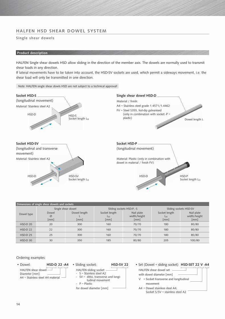
HSD-D HSD-S
HSD-D HSD-SV HSD-D HSD-P
Dimensions of single shear dowels and sockets
Dowel type
Single shear dowel Sliding sockets HSD-P, -S Sliding sockets HSD-SVDowel
Ø[mm]
Dowel lengthL
[mm]
Socket length LH
[mm]
Nail platewidth/height
[mm]
Socket length LH
[mm]
Nail platewidth/height
[mm]
HSD-D 20 20 300 160 70/70 180 80/80
HSD-D 22 22 300 160 70/70 180 80/80
HSD-D 25 25 300 160 70/70 180 80/80
HSD-D 30 30 350 185 80/80 205 100/80
HSD-D 22 -A4 HSD-SV 22 HSD-SET 22 V -A4
HALFEN HSD SHEAR DOWEL SYSTEM
HALFEN Single shear dowels HSD allow sliding in the direction of the member axis. The dowels are normally used to transmit shear loads in any direction. If lateral movements have to be taken into account, the HSD-SV sockets are used, which permit a sideways movement, i.e. the shear load will only be transmitted in one direction.
Single shear dowels
Product description
Single shear dowel HSD-DSocket HSD-S (longitudinal movement)
Socket HSD-P (longitudinal movement)
Socket HSD-SV (longitudinal and transverse movement)
Socket length LSocket length LHH Dowel length L Dowel length L
Material: Stainless steel A2
Material: Stainless steel A2 Material: Plastic (only in combination with dowel in material / finish FV)
Material / finish:
A4 = Stainless steel grade 1.4571/1.4462
FV = Steel S355, hot-dip galvanised (only in combination with socket -P = plastic)
Ordering examples:
Sliding socket:•
Socket length LSocket length LHH Socket length LSocket length LHH
Set (Dowel + sliding socket)•
HALFEN shear dowelDiameter [mm]A4 = Stainless steel A4 material
HALFEN sliding socketS = Stainless steel A2 -SV = ditto, transverse and longi- -
tudinal movement P = Plastic -
for dowel diameter [mm]
Dowel:•
HALFEN shear dowel set
with dowel diameter [mm]
V = Socket transverse and longitudinal
movement
A4 = Dowel stainless steel A4, Socket S/SV = stainless steel A2
Note: HALFEN single shear dowls HSD are not subject to a technical approval!

15
lc
ar emin emin
h min
f
Ø ds Ø ds
Dimensioning resistances VRd.s and VRd.c [kN] for non-reinforced concrete
Dowel type Concrete grade Dowel-Ø[mm]
Minimum component
thickness [mm]
Design resistances [kN]for joint width f [mm]
10 20 30 40
HSD-D 20
≥ C20/25
20 320 9.5 7.1 5.7 4.8
HSD-D 22 22 350 11.6 9.0 7.3 6.1
HSD-D 25 25 400 15.2 12.0 9.9 8.4
HSD-D 30 30 480 22.2 17.5 14.5 12.3
Minimum spacing, Element thickness, Stirrup spacing
Dowel Ø Socket Stirrup Ø
ds[mm]
Component thickness
hmin[mm]
Stirrup spacing
lc[mm]
Required dowel spacing
emin[mm]
Edge distance
ar[mm][mm]
20HSD-S
+ HSD-P
10 160 60 310 160 lc
hmin
emin
ar
= Distance of the first stirrup from the dowel
= Minimum component thickness
= Minimum centre spacing between the single
dowels
= Minimum edge distance
22 10 160 60 350 175
25 12 175 70 410 200
30 14 210 90 560 240
20
HSD-SV
10 160 80 310 16022 10 160 90 350 17525 12 175 100 410 200
30 14 210 110 560 240
HALFEN HSD SHEAR DOWEL SYSTEM
Single shear dowels
Dimensioning
Steel load-bearing capacity: VRd,s = fμ × 1,25 × (fyk/γMS) × W / (f+Ø)Concrete load-bearing capacity: VRd,c = 0,4 × fck × Ø2,1 / (333+12,2 × f) 0,4 = (α × γMW) / 3
with:fμ = 0,9 Reductions factor due to friction [-]fyk = Yielding point [N/mm²] fck = characteristic cylinder resistance to pressure of the concrete [N/mm²]f = Joint width [mm]Ø = Shear dowel diameter [mm]W = Section modulus [mm³]γMS = Material safety factor for steel [-]
HALFEN Single shear dowels HSD-D require no official • approval.α• = 0,85 (consideration of the long-term effects)γ• MW = 1,425 (average value from γG = 1,35 and γQ = 1,5)Minimum edge distance to the dowel axis a• r = 8 × Ø (in all directions)Minimum axial distance e = 16 × Ø•
Design resistances HSD-D in non-reinforced concrete according to volume 346, DAfStb (German association for reinforced con-crete construction)
Dimensioning for non-reinforced concrete
16
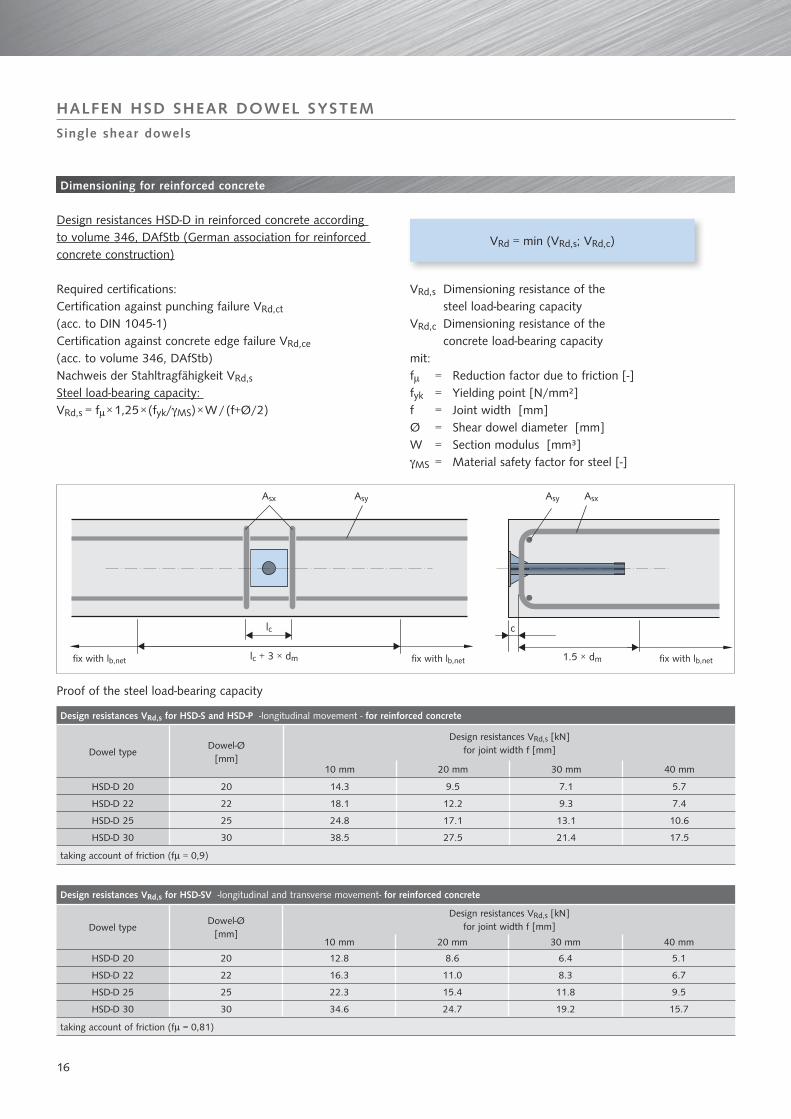
Asx Asy
lc c
lc + 3 × dm 1,5 × dm
AsxAsy
HALFEN HSD SHEAR DOWEL SYSTEM
Single shear dowels
Dimensioning for reinforced concrete
Required certifications: Certification against punching failure VRd,ct (acc. to DIN 1045-1)Certification against concrete edge failure VRd,ce
(acc. to volume 346, DAfStb)Nachweis der Stahltragfähigkeit VRd,s
Steel load-bearing capacity: VRd,s = fμ × 1,25 × (fyk/γMS) × W / (f+Ø/2)
Design resistances VRd,s for HSD-S and HSD-P -longitudinal movement - for reinforced concrete
Dowel typeDowel-Ø
[mm]
Design resistances VRd,s [kN]for joint width f [mm]
10 mm 20 mm 30 mm 40 mm
HSD-D 20 20 14.3 9.5 7.1 5.7
HSD-D 22 22 18.1 12.2 9.3 7.4
HSD-D 25 25 24.8 17.1 13.1 10.6
HSD-D 30 30 38.5 27.5 21.4 17.5
taking account of friction (fμ = 0,9)
VRd = min (VRd,s; VRd,c)
VRd,s Dimensioning resistance of the steel load-bearing capacityVRd,c Dimensioning resistance of the concrete load-bearing capacity mit:fμ = Reduction factor due to friction [-]fyk = Yielding point [N/mm²] f = Joint width [mm]Ø = Shear dowel diameter [mm]W = Section modulus [mm³]γMS = Material safety factor for steel [-]
Design resistances VRd,s for HSD-SV -longitudinal and transverse movement- for reinforced concrete
Dowel typeDowel-Ø
[mm]
Design resistances VRd,s [kN]for joint width f [mm]
10 mm 20 mm 30 mm 40 mm
HSD-D 20 20 12.8 8.6 6.4 5.1
HSD-D 22 22 16.3 11.0 8.3 6.7
HSD-D 25 25 22.3 15.4 11.8 9.5
HSD-D 30 30 34.6 24.7 19.2 15.7
taking account of friction (fμ = 0,81)
fix with lb,net fix with lb,net fix with lb,net
Design resistances HSD-D in reinforced concrete according to volume 346, DAfStb (German association for reinforced concrete construction)
Proof of the steel load-bearing capacity
1.5 × dm

17
Dimensioning resistances VRd,c for HSD-S and HSD-P -longitudinal movement -
Dowel typeComponent thickness h cnom
Design resistances In-situ reinforcement Centre spacing
VRd,c [kN] Asx Asy Ic
[mm] [mm] ≥ C20/25 [mm]
HSD-D 20≥160
3014.2
2 Ø 10 2 Ø 10 60≥180 15.8
HSD-D 22
≥160
30
14.2
2 Ø 10 2 Ø 10 60
≥180 15.8
≥200 17.3
≥220 18.9
≥240 20.4
HSD-D 25
≥180
30
20.5
2 Ø12 2 Ø12 70
≥200 22.4
≥220 24.3
≥240 26.2
≥260 28.0
HSD-D 30
≥220
30
29.3
2 Ø 14 2 Ø 14 90
≥240 31.5
≥260 33.7
≥280 35.9
≥300 38.1
≥320 40.2
taking account of friction (fμ = 1,0)
Dimensioning resistances VRd,c for HSD-SV -longitudinal and transverse movement-
Dowel typeComponent thickness h cnom
Design resistances In-situ reinforcement Centre spacing
VRd,c [kN] Asx Asy Ic[mm] [mm] ≥ C20/25 [mm]
HSD-D 20≥160
305)
2 Ø 10 2 Ø 10 80≥180 13.0
HSD-D 22
≥160
30
5)
2 Ø 10 2 Ø 10 90
≥180 12.5
≥200 13.9
≥220 15.3
≥240 16.7
HSD-D 25
≥180
30
5)
2 Ø12 2 Ø12 100
≥200 18.0
≥220 19.8
≥240 21.5
≥260 23.2
HSD-D 30
≥220
30
24.6
2 Ø 14 2 Ø 14 110
≥240 26.7
≥260 28.7
≥280 30.7
≥300 32.7
≥320 34.7
taking account of friction (fμ = 0,9) 5) No rear suspension stirrup in the break-out cone
The design resistance for the concrete load-bearing capacity is the smallest dimensioning resistance from the concrete edge failure and punching failure proofs:
HALFEN HSD SHEAR DOWEL SYSTEM
Single shear dowels
Proof of the concrete load-bearing capacity
Dimensioning for reinforced concrete
Asx = Rear suspension reinforcementAsy = Longitudinal reinforcementlc = Distance of the first stirrup to the dowel

18
1
2
3, 4
5a
5b
6
1. Fixing to the formwork
Nail the socket onto the formwork according to the specified
position. Important: The socket must be aligned exactly in the
direction of slide.
NOTE: Do not remove the label. This protects the socket from
the penetration of fresh concrete.
2. Reinforcement
Laying of the in-situ joint and rear suspension reinforcement, as well as the component reinforcement, in the 1st concreting-section.
4. Joint material
Application of the joint material. The positions of the shear dowel sockets are to be exactly marked where necessary.
5. a) Shear dowel
The dowel that matches the socket is now inserted through the joint material and is pushed into the socket up to the stop (safety plug).
5. b) Shear dowel
In the case of fire protection requirements according to DIN 4102, a recess is to be provided in the joint material for the HALFEN fire protection pad.
6. Concreting
Positioning of the reinforcement (by contractor) and concreting the 2nd concreting -section.
Fire protection pad HSD-F
3. Protective label
The protective label can be removed from the socket after the concreting and the removal of the formwork.
HALFEN HSD SHEAR DOWEL SYSTEM
Assembly instructions for HSD single shear dowels
Single shear dowels

CONTACT HALFEN WORLDWIDE
HALFEN is represented with subsidiaries in the following 14 countries, please contact us:
NOTES REGARDING THIS CATALOGUETechnical and design changes reserved. The information in this publication is based on state-of-the-art technology at the time of publication. We reserve the right to make technical and design changes at any time. Halfen GmbH shall not accept liability for the accuracy of the information in this publication or for any printing errors.
The Quality Management System of Halfen GmbH is certified for the locations in Germany, Switzerland and Poland according to DIN EN ISO 9001:2000, Certificate No. QS-281 HH.
Furthermore HALFEN is represented with sales offices and distributors worldwide. Please contact us: www.halfen.com
Austria HALFEN Gesellschaft m.b.H.Leonard-Bernstein-Str. 101220 Wien
Phone: +43 - 1 - 259 6770 E-Mail: [email protected]: www.halfen.at
Fax: +43 - 1 - 259 - 6770 99
Belgium/Luxembourg HALFEN-FRIMEDA N.V.Borkelstraat 1312900 Schoten
Phone: +32 - 3 - 658 07 20E-Mail: [email protected]: www.halfen.be
Fax: +32 - 3 - 658 15 33
China HALFEN Construction Accessories Distribution Co.Ltd.Room 601 Tower D, Vantone CentreNo.A6 Chao Yang Men Wai StreetChaoyang District Beijing · P.R. China 100020
Phone: +86 - 10 5907 3200E-Mail: [email protected]: www.halfen.cn
Fax: +86 - 10 5907 3218
Czech Republic HALFEN-DEHA s.r.o.K Vypichu 986 · Komerčni zóna Rudná, hala 625219 Rudná
Phone: +420 - 311 - 690 060E-Mail: [email protected]: www.halfen-deha.cz
Fax: +420 - 311 - 671 416
France HALFEN S.A.S.18, rue Goubet75019 Paris
Phone: +33 - 1 - 445231 00E-Mail: [email protected]: www.halfen.fr
Fax: +33 - 1 - 445231 52
Germany HALFEN-DEHA Vertriebsgesellschaft mbHKatzbergstraße 3 40764 Langenfeld
Phone: +49 - 2173 - 970 0E-Mail: [email protected]: www.halfen.de
Fax: +49 - 2173 - 970 225
Italy HALFEN-DEHA S.r.l. Soc. UnipersonaleVia F.lli Bronzetti N° 2824124 Bergamo
Phone: +39 - 035 - 0760711E-Mail: [email protected]: www.halfen.it
Fax: +39 - 035 - 0760799
Netherlands HALFEN b.v.Vonderweg 57468 DC Enter
Phone: +31 - 547 - 3830 30E-Mail: [email protected]: www.halfen.nl
Fax: +31 - 547 - 3830 35
Norway HALFEN-FRIMEDA ASPostboks 20804095 Stavanger
Phone: +47 - 51 82 34 00E-Mail: [email protected]: www.halfen.no
Fax: +47 - 51 82 34 01
Poland HALFEN Sp. z o.o.Ul. Obornicka 28760-691 Poznan
Phone: +48 - 61 - 622 14 14E-Mail: [email protected]: www.halfen.pl
Fax: +48 - 61 - 622 14 15
Spain HALFEN-DEHA S.L.c/ Fuente de la Mora 2, 2° D28050 Madrid
Phone: +34 - 91 - 632 18 40E-Mail: [email protected]: www.halfen.es
Fax: +34 - 91 - 633 42 57
Sweden HALFEN ABBox 150435 23 Mölnlycke
Phone: +46 - 31 - 98 58 00E-Mail: [email protected]: www.halfen.se
Fax: +46 - 31 - 98 58 01
Switzerland HALFEN Swiss AGIndustriestrasse 32 8108 Dällikon
Phone: +41 - 44 - 849 78 78E-Mail: [email protected]: www.halfen.ch
Fax: +41 - 44 - 849 78 79
United Kingdom /Ireland
HALFEN Ltd.Humphrys Road · Woodside EstateDunstable LU5 4TP
Phone: +44 - 1582 - 47 03 00E-Mail: [email protected]: www.halfen.co.uk
Fax: +44 - 1582 - 47 03 04

For further information please contact: www.halfen.com
© 2
008
Hal
fen
Gm
bH, G
erm
any
appl
ies
also
to
copy
ing
in e
xtra
cts.
R -
080
- EE
- 09/
08
1.00
0 0
9/08