HALFEN HEK PRECAST COUPLER - downloads.halfen.com · HALFEN HEK PRECAST COUPLER General note This...
22
HALFEN HEK PRECAST COUPLER CONCRETE Z_HEK 02/18-E
Transcript of HALFEN HEK PRECAST COUPLER - downloads.halfen.com · HALFEN HEK PRECAST COUPLER General note This...

HALFEN HEK PRECAST COUPLER
CONCRETE
Z_HEK 02/18-E

HALFEN HEK PRECAST COUPLER
Genera l note
This approval only applies to original HALFEN products manufactured by HALFEN. The specifi cations in this approval are not transferable to other products. Users are fully liable for personel injuries and material damage caused by third-party products used instead of HALFEN products.
Use of third-party products
Date
National Technical Approval 30th January 2018
30th January 2018
30th January 2023
Ref no.:
| 25-1.21.8-68/16
The aforementioned construction product is herewith granted a general building authority approval. This general building authority approval comprises seven pages and eleven annexes.
HALFEN HEK Precast coupler
This translation of the original German version of theNational Technical Approval no. Z-21.8-2086 is
not authorized by the Deutsches Institut für Bautechnik.
Note: This translation of the original German version has not been verifi ed by the Deutsches Institut für Bautechnik.
Period of validity:
Applicant:
Approved product:
HALFEN GmbHLiebigstraße 1440764 Langenfeld
Z-21.8-2086
Expires on:
Valid from:
Approval number:
Deutsches Institut für Bautechnik (DIBt)(National and Federal State approved statutory public body)
Kolonnenstrasse 30 B, D-10829 Berlin, GermanyTel.: +49 30 78730-0 | Fax: +49 30 78730-320Email: [email protected] | www.dibt.de
Member of the EOTA, UEAtc and WFTAO
Technical assessment institute for construction products and methods:
This national technical approval verifi es the usability and applicability of the aforementioned construction product in accordance with the Landesbauordnungen (Regional Building Codes of the German Federal States).
I. GENERAL PROVISIONS
1.
National technical approval no. Z-21.8-2086
page 2 of 7 | 30th January 2018
The national technical approval does not replace any permits, approvals and certifi cates legally required for the execution of building projects.
The granting of this national technical approval does not aff ect the legal rights of any third party;in particular those pertaining to private protection laws.
The manufacturer and distributor of the aforementioned construction product must make copies of the national technical approval available to the purchaser i.e. the end-user irrespective of further regulations as stated in the “Specifi c Provisions”, and must give notice that the national technical approval for the product must be available at the point of application. Copies of the national techni-cal approval must be made available to the respective authorities on request.
Reproductions or copies of this national technical approval must always be in full. Reproduction in extracts requires the consent of the Deutsches Institut für Bautechnik. Text and illustration used in advertising material must not contradict this national technical approval. Translations of the national technical approval must include a disclaimer as follows "This translation of the original German version is not authorized by the Deutsches Institut für Bautechnik’” (Vom Deutschen Institut für Bautechnik nicht geprüfte Übersetzung der deutschen Originalfassung).
This national technical approval can be revoked at any time. The provisions of this national technical approval may be subsequently amended or modifi ed, especially if technical progress makes this neces-sary.
This approval also includes a general building authority approval. The general type approval provided by this certifi cate may also be regarded as a general building authority design approval certifi cate.
This approval is based on the specifi cations and documents submitted by the applicant. Any changeto these basic specifi cations are to be made available to the the Deutsches Institut für Bautechnik without delay.
2.
3.
4.
5.
6.
7.
8.
Note: This translation of the original German version has not been verifi ed by the Deutsches Institut für Bautechnik.

National technical approval no. Z-21.8-2086
page 3 of 7 | 30th January 2018
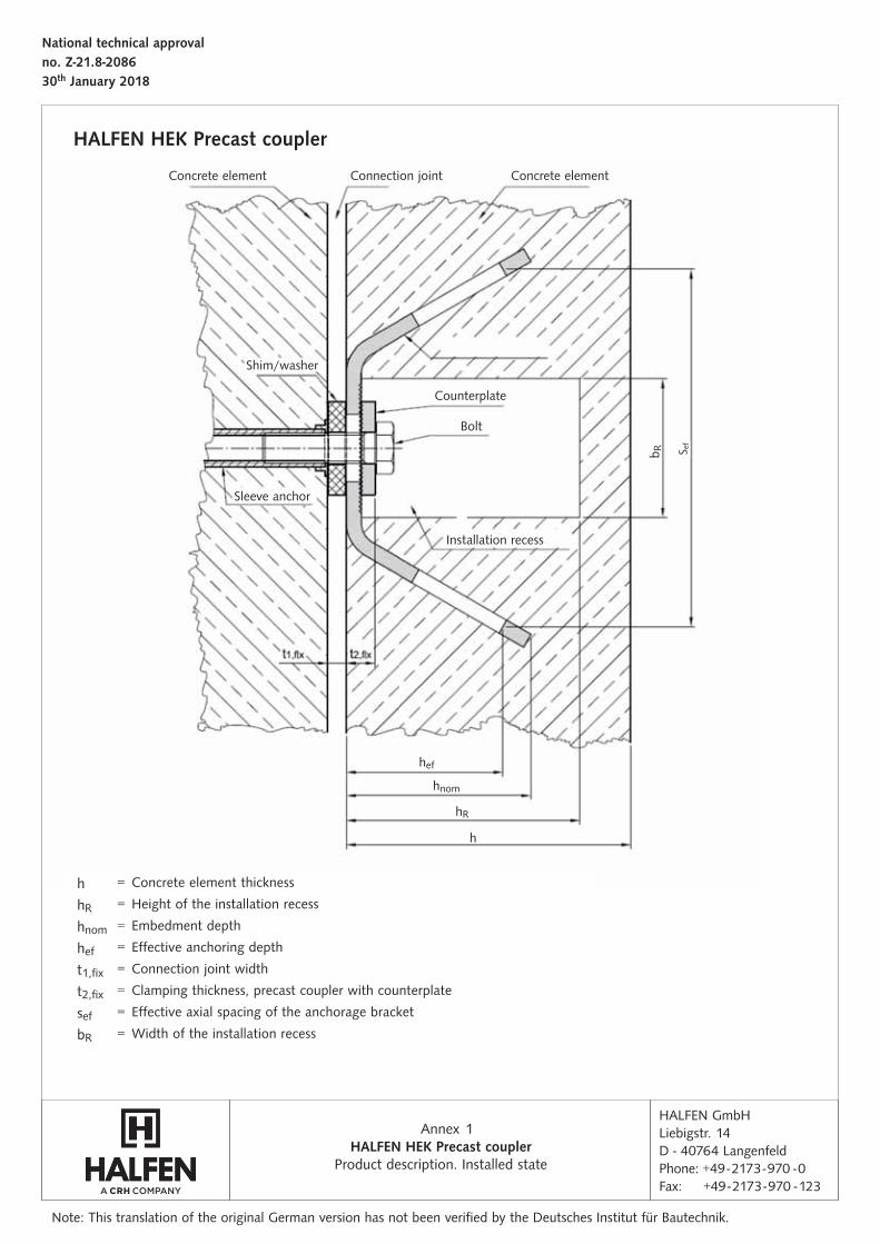
The HALFEN HEK Precast coupler is shown in an installed state in annex 1.
The object of this national technical approval is the HALFEN HEK Precast coupler, which is used to con-nect two concrete precast elements together. The precast coupler consists of a symmetrically shaped steel bracket (Types HEK2 T-100 and HEK2 L-100) and a square counterplate made of hot-dip galvanized or stainless steel material. The HEK Precast coupler is cast in, fl ush with the concrete surface with a recess for installation in a precast concrete element. Counterplates and bolts in the installation recess are used together with anchorage elements (for example, sleeve anchors or anchor channels) in the second precast component to positively lock the elements.
The HALFEN HEK Precast coupler may be used as anchorage in connections under static or quasi-static load in reinforced and non-reinforced normal concrete of strength class of at least C20/25 and at most C50/60 according to DIN EN 206-1:2001-07: Concrete - Part 1: "Specifi cation, performance, production and conformity".The HEK Precast coupler may only be used in the installation applications as shown in Appendix 5.
The Precast coupler may be anchored in cracked and non-cracked concrete.
The hot-dip galvanized steel precast coupler may only be used in dry indoor conditions, e. g. in residential buildings, offi ces, schools, hospitals, and in retail facilities; with the exception of wet rooms.
The stainless steel HEK Precast coupler is produced in material of corrosion resistance class CRC III and can therefore be used in accordance with DIN EN 1993--1-4:2015-10 with DIN EN 1993-1-4/NA: 2017-01.
The application of the HEK Precast coupler is in accordance with DIN EN 1992-1-1:2011-01 and with DIN EN 1992-1-1/NA:2013-04, if all the steel parts are subsequently completely embedded with grouting mortar cement in the recess and joint in accordance with the DAfStb* Guideline, “Preparation and appli-cation of cement based grouting concrete and grouting mortar”.
II. SPECIFIC PROVISIONS
Object of approval and intended use
Area of application
Properties and materials
1.1
1.2
2
2.1
Provisions for the construction product
* DAfStb Deutscher Ausschuss für Stahlbeton = (German Committee for Structural Concrete)
The HALFEN HEK Precast coupler must be consistent with the drawings and specifi cations in the annexes of this document.The material properties, dimensions and tolerances for the precast coupler not specifi ed in this general building authority’s approval must correspond to the specifi cations deposited with the German Institute for Structural Engineering, the certifi cation body and the third party inspection authority.
The extent, type and frequency of factory production control is determined by the inspection plan deposited with the Deutsches Institut für Bautechnik and the third-party certifi cation body.The results of the factory production control must be documented and evaluated and must include at minimum the following:
Each manufacturing plant must set up and implement an in-house, factory production control. Factory production control is understood as the continuous internal monitoring of the production process, implemented by the manufacturer, to ensure the precast coupler (HEK2 T-100 and HEK2 L-100; steel element and counterplate) manufactured by them are in conformity with the provisions of this national technical approval.
The documents must be kept for at least fi ve years and be submitted to the inspection body responsible for third-party inspection. On request, these records must be made available to the Deutsches Institut für Bautechnik and to the responsible building authority (obersten Bauaufsichtsbehörde).
2.3.2 Factory production controls
Confi rmation of conformity with the specifi cations for the precast coupler (HEK2 T-100 and HEK2 L-100; steel element and counterplate) with the specifi cations of this approval must be provided for each manufacturing location with a declaration of conformity based on a factory production control. The certifi cate of conformity must be issued by a recognized body; also required is regular third party monitoring by an approved inspection body in accordance with the following provisions:
The Deutsches Institut für Bautechnik must also be provided with a copy of the initial test report.
– method of test or inspection– identifi cation of the construction product, raw material or components
– production date, test date of the construction product, raw material or components– results of the inspection and tests, and evaluation against the requirements– signature of the person responsible for factory quality control plan
The manufacturer of the construction product must contract an approved certifi cation body for independent inspection and to issue a certifi cate of conformity as well as an approved inspection body for relevant product testing.
The manufacturer is required to mark the precast coupler with a conformity mark (Ü-mark) including a declaration of the intended use.
A copy of the certifi cate of conformity issued by the certifi cation body must be submitted to the Deutsches Institut für Bautechnik.
Verifi cation of conformity
General information
2.3
2.3.1
2.2 Marking
The marking may only be used if the conditions in accordance with section 2.3 are met.
Each precast coupler must be marked as illustrated in annex 4.
The packaging, enclosed documents or shipping documents for the precast coupler (HEK2 T-100 and the HEK2 L-100; steel element and counterplate) must be marked by the manufacturer with the confor-mity mark (Ü-mark) in accordance with the conformity mark regulations of the Federal states. In addition, the manufacturer's identifi cation mark, the approval number and the complete name of the precast coupler must be declared.
National technical approval no. Z-21.8-2086
page 4 of 7 | 30th January 2018
Note: This translation of the original German version has not been verifi ed by the Deutsches Institut für Bautechnik.

National technical approval no. Z-21.8-2086
page 5 of 7 | 30th January 2018
Note: This translation of the original German version has not been verifi ed by the Deutsches Institut für Bautechnik.
In case of unsatisfactory test results the manufacturer must take immediate action to resolve the defi ciency. Construction products which do not comply with the requirements must be handled in a manner to ensure they cannot be mistaken for products complying with the requirements. After a problem has been resolved, the respective test must be repeated immediately; as far as this is technically feasible and necessary to verify that the defi ciency has been eliminated.
Third-party controls2.3.3
In each manufacturing plant for the precast coupler (HEK2 T-100 and HEK2 L-100; steel element and counterplate), factory production control must be reviewed at regular intervals by an independent body, at least once a year.
Independent inspection must include an initial test of the precast coupler and samples taken for random inspections. The respective approved inspection body is responsible for taking samples and testing.
The extent, type and frequency of third-party control is as recorded in the document deposited with the Deutsches Institut für Bautechnik and the third-party monitoring authority. The results of the certifi cation and third-party control must be kept for at least fi ve years. On request, they must be made available by the appointed certifi cation or inspection body to the Deutsches Institut für Bautechnik and to the responsible building authority (obersten Bauaufsichtsbehörde).
The precast connection must be planned and dimensioned according to standard engineering practices.Verifi able calculations and construction drawings must be prepared taking the loads to be anchored into account. The design drawings must include the exact location of the precast coupler and information on the allowable bolts.When designing, the HALFEN HEK Precast coupler is to be regarded as similar to a double fastening using headed anchors.Details for the possible directions of loading (actions) for types HEK2 T-100 and HEK2 L-100 can be found in annex 2 and 3.The design of the precast coupler should be in accordance with DIN SPEC 1021-4-2:2009-08 " Design of fastenings for use in concrete" Part 4-2: Headed fasteners; (German version CEN/TS 1992-4-2:2009) considering the following notes and additions.Verifi cation of the immediate local force transfer to the concrete has been provided. Verifi cation of the transfer of the loads to be anchored to the building component must be provided separately.Additional stresses that may occur in the precast coupler, in the connected component or in the component in which the precast coupler is anchored caused by constrained deformation must be taken into account (for example: temperature fl uctuations).The load-bearing capacities of the precast elements and the anchoring elements in the second precast con-crete element (e. g. sleeve anchor and bolt) are not subject of this approval and must be verifi ed separately.The installation specifi cations and dimensions of the precast connector can be found in annex 5, table 6.(Spacing and edge distances, concrete component thickness and dimensions of the installation recess).
Specifi cations for application of the object of approval 3
3.1.1
3.1
General information
Design and dimensioning

National technical approval no. Z-21.8-2086
page 6 of 7 | 30th January 2018
Note: This translation of the original German version has not been verifi ed by the Deutsches Institut für Bautechnik.
3.1.2
3.1.3
Verifi cation according to DIN SPEC 1021-4-2:2009-08
Supplementary reinforcement according to DIN SPEC 1021-4-2:2009-08
The characteristic values provided for verifi cations according to DIN SPEC 1021-4-2:2009-08 given in the tables in annexes 6 to 9 must be used.The provisions and illustrations of projected areas in annexes 6 to 10 must be observed for verifi cation of concrete failure.
Weakening of the concrete cross-section caused by the installation recess for the precast coupler must be taken into account in the verifi cation.
When supplementary reinforcement is used, it is not required to provide verifi cation for concrete cone failure or concrete edge failure in the event of tensile or shear stress. The requirements of DIN SPEC 1021-4-2:2009-08, sections 6.2.2 and 6.3.2 apply for supplementary reinforcement. Annex 11 must also be observed when detailing the supplementary reinforcement.
The assembly and installation of the precast coupler must be in accordance with the design drawings prepared in accordance with section 3.1.1.
The precast coupler must be installed in accordance with the manufacturer's installation instructions and the information provided in annex 5. The required recesses for installation must be kept free by using the correct recess formers when pouring concrete. These are removed after the concrete has cured and hardened.The precast coupler must be securely fi xed to the formwork to ensure it cannot move when installing the reinforcement or when pouring and compacting the concrete.The serration (see annexes 2 and 3) in the precast coupler must be protected from concrete.Extra care is required when compacting the concrete to avoid signifi cant voids, particularly under the anchor fl anges of the precast coupler.
Always observe the installation instructions provided by the manufacturer of the precast coupler for connection of precast concrete elements.The precast coupler counterplate is inserted into the installation recess together with the bolt. The counterplate must have full contact with the serrated area of the precast coupler, must engage properly with the serration and be secured by turning the bolt. The bolt may only be screwed into an approved anchor sleeve.Shimming is required under the precast coupler connector in accordance with annex 1 if a construction joint is planned between the precast concrete elements.The tightening torques for the bolts as specifi ed in annex 5, table 5 must be observed.
3.23.2.1
3.2.2
3.2.3
Application instructions
Installation of the precast coupler in the precast concrete element
Connection and fi xing of the second precast concrete element
Introduction

National technical approval no. Z-21.8-2086
page 7 of 7 | 30th January 2018
Note: This translation of the original German version has not been verifi ed by the Deutsches Institut für Bautechnik.
Beatrix WittstockReferatsleiter (Head of Division)
The responsible contractor or a designated site manager or a designated competent representative must be present when installing the precast coupler, and also on site for fi nal assembly of the concrete elements. It is their responsibility to ensure the work is carried out properly and document the installa-tion and assembly. They are also responsible for checking the position of the precast coupler and the optional supplementary reinforcement.
The documentation must remain available on site during the construction period and submitted to inspection personnel on request. The documentation, with the delivery notes, must be kept by the contractor for at least fi ve years after completion of the project.
3.2.4 Checking the installation
hef
HALFEN GmbHLiebigstr. 14D - 40764 LangenfeldPhone: +49 - 2173 - 970 - 0Fax: +49 - 2173 - 970 - 123
Annex
National technical approval no. Z-21.8-208630th January 2018
Note: This translation of the original German version has not been verifi ed by the Deutsches Institut für Bautechnik.
HALFEN HEK Precast coupler
Connection joint Concrete elementConcrete element
Bolt
s ef
b R
Installation recess
hnom
hR
h
Counterplate
Shim/washer
Sleeve anchor
HALFEN HEK Precast coupler1
Product description. Installed state
h = Concrete element thickness
hR = Height of the installation recess
hnom = Embedment depth
hef = Effective anchoring depth
t1,fix = Connection joint width
t2,fix = Clamping thickness, precast coupler with counterplate
sef = Effective axial spacing of the anchorage bracket
bR = Width of the installation recess
S ef
HALFEN GmbHLiebigstr. 14D - 40764 LangenfeldPhone: +49 - 2173 - 970 - 0Fax: +49 - 2173 - 970 - 123
Annex
National technical approval no. Z-21.8-208630th January 2018
Note: This translation of the original German version has not been verifi ed by the Deutsches Institut für Bautechnik.
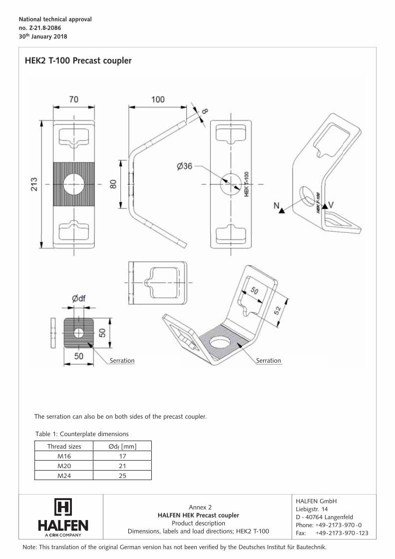
Product descriptionDimensions, labels and load directions; HEK2 T-100
HALFEN HEK Precast coupler2
HEK2 T-100 Precast coupler
The serration can also be on both sides of the precast coupler.
Serration Serration
Table 1: Counterplate dimensions
Thread sizes Ødf [mm]
M16 17
M20 21
M24 25
HALFEN GmbHLiebigstr. 14D - 40764 LangenfeldPhone: +49 - 2173 - 970 - 0Fax: +49 - 2173 - 970 - 123
Annex
National technical approval no. Z-21.8-208630th January 2018
Note: This translation of the original German version has not been verifi ed by the Deutsches Institut für Bautechnik.
HALFEN HEK Precast coupler3
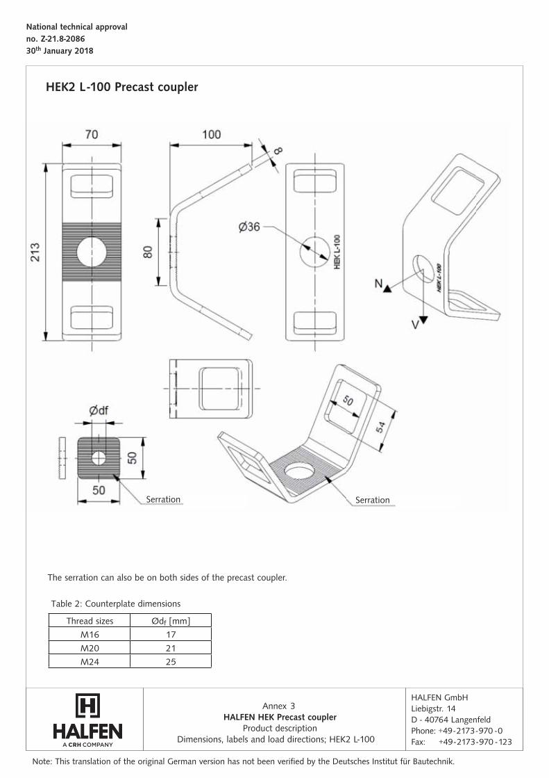
Thread sizes Ødf [mm]
M16 17
M20 21
M24 25
HEK2 L -100 Precast coupler
Product descriptionDimensions, labels and load directions; HEK2 L-100
Table 2: Counterplate dimensions
SerrationSerration
The serration can also be on both sides of the precast coupler.
HALFEN GmbHLiebigstr. 14D - 40764 LangenfeldPhone: +49 - 2173 - 970 - 0Fax: +49 - 2173 - 970 - 123
Annex
National technical approval no. Z-21.8-208630th January 2018
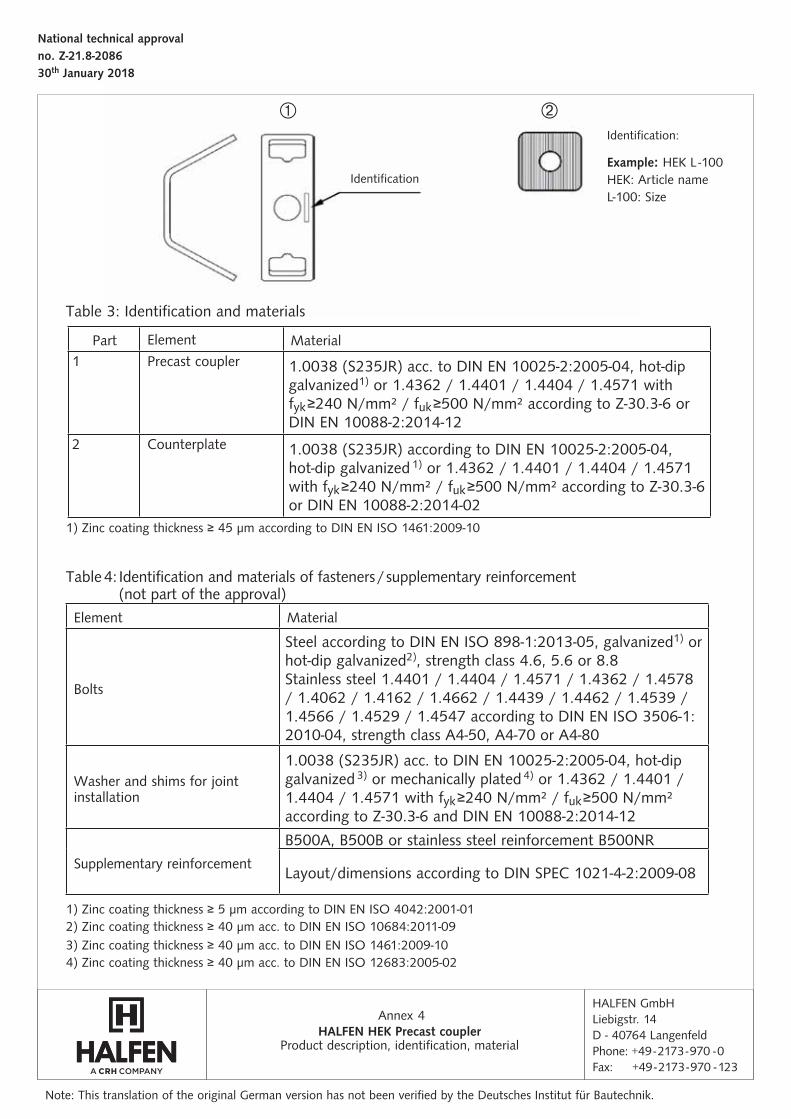
Product description, identifi cation, materialHALFEN HEK Precast coupler
4
Part Element Material1 Precast coupler 1.0038 (S235JR) acc. to DIN EN 10025-2:2005-04, hot-dip
galvanized1) or 1.4362 / 1.4401 / 1.4404 / 1.4571 with fyk ≥240 N/mm² / fuk ≥500 N/mm² according to Z-30.3-6 or DIN EN 10088-2:2014-12
2 Counterplate 1.0038 (S235JR) according to DIN EN 10025-2:2005-04, hot-dip galvanized 1) or 1.4362 / 1.4401 / 1.4404 / 1.4571 with fyk ≥240 N/mm² / fuk ≥500 N/mm² according to Z-30.3-6 or DIN EN 10088-2:2014-02
Element Material
Bolts
Steel according to DIN EN ISO 898-1:2013-05, galvanized1) or hot-dip galvanized2), strength class 4.6, 5.6 or 8.8Stainless steel 1.4401 / 1.4404 / 1.4571 / 1.4362 / 1.4578 / 1.4062 / 1.4162 / 1.4662 / 1.4439 / 1.4462 / 1.4539 / 1.4566 / 1.4529 / 1.4547 according to DIN EN ISO 3506-1:2010-04, strength class A4-50, A4-70 or A4-80
Washer and shims for joint installation
1.0038 (S235JR) acc. to DIN EN 10025-2:2005-04, hot-dip galvanized 3) or mechanically plated 4) or 1.4362 / 1.4401 / 1.4404 / 1.4571 with fyk ≥240 N/mm² / fuk ≥500 N/mm² according to Z-30.3-6 and DIN EN 10088-2:2014-12
Supplementary reinforcement
B500A, B500B or stainless steel reinforcement B500NR
Layout/dimensions according to DIN SPEC 1021-4-2:2009-08
Example: HEK L -100HEK: Article nameL-100: Size
Note: This translation of the original German version has not been verifi ed by the Deutsches Institut für Bautechnik.
Identifi cation
Identifi cation:
1) Zinc coating thickness ≥ 5 μm according to DIN EN ISO 4042:2001-01
1) Zinc coating thickness ≥ 45 μm according to DIN EN ISO 1461:2009-10
2) Zinc coating thickness ≥ 40 μm acc. to DIN EN ISO 10684:2011-093) Zinc coating thickness ≥ 40 μm acc. to DIN EN ISO 1461:2009-104) Zinc coating thickness ≥ 40 μm acc. to DIN EN ISO 12683:2005-02
Table 3: Identification and materials
Table 4: Identification and materials of fasteners / supplementary reinforcement (not part of the approval)
HALFEN GmbHLiebigstr. 14D - 40764 LangenfeldPhone: +49 - 2173 - 970 - 0Fax: +49 - 2173 - 970 - 123
Annex
National technical approval no. Z-21.8-208630th January 2018
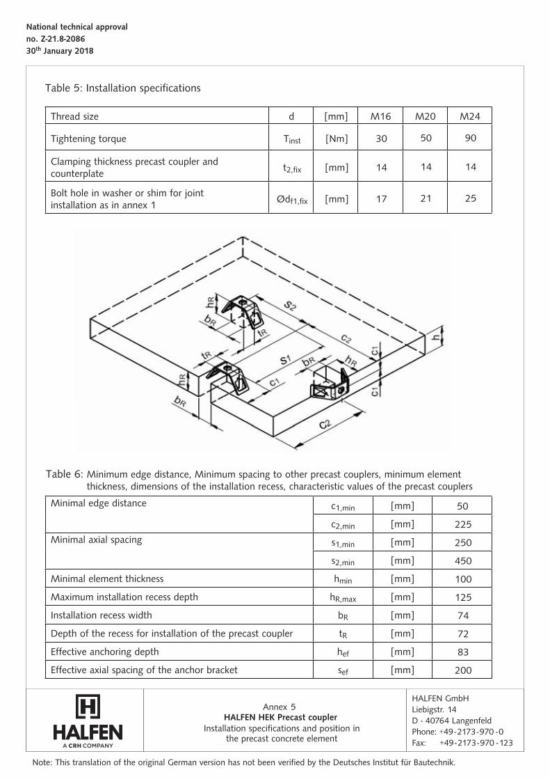
Installation specifi cations and position in the precast concrete element
5
Note: This translation of the original German version has not been verifi ed by the Deutsches Institut für Bautechnik.
Thread size d [mm] M16 M20 M24
Tightening torque Tinst [Nm] 30 50 90
Clamping thickness precast coupler and counterplate
t2,fix [mm] 14 14 14
Bolt hole in washer or shim for joint installation as in annex 1
Ødf1,fix [mm] 17 21 25
Minimal edge distance c1,min [mm] 50
c2,min [mm] 225
Minimal axial spacing s1,min [mm] 250
s2,min [mm] 450
Minimal element thickness hmin [mm] 100
Maximum installation recess depth hR,max [mm] 125
Installation recess width bR [mm] 74
Depth of the recess for installation of the precast coupler tR [mm] 72
Effective anchoring depth hef [mm] 83
Effective axial spacing of the anchor bracket sef [mm] 200
HALFEN HEK Precast coupler
Table 5: Installation specifications
Table 6: Minimum edge distance, Minimum spacing to other precast couplers, minimum element thickness, dimensions of the installation recess, characteristic values of the precast couplers
HALFEN GmbHLiebigstr. 14D - 40764 LangenfeldPhone: +49 - 2173 - 970 - 0Fax: +49 - 2173 - 970 - 123
Annex
National technical approval no. Z-21.8-208630th January 2018
Characteristic values for tension loads
6
Note: This translation of the original German version has not been verifi ed by the Deutsches Institut für Bautechnik.
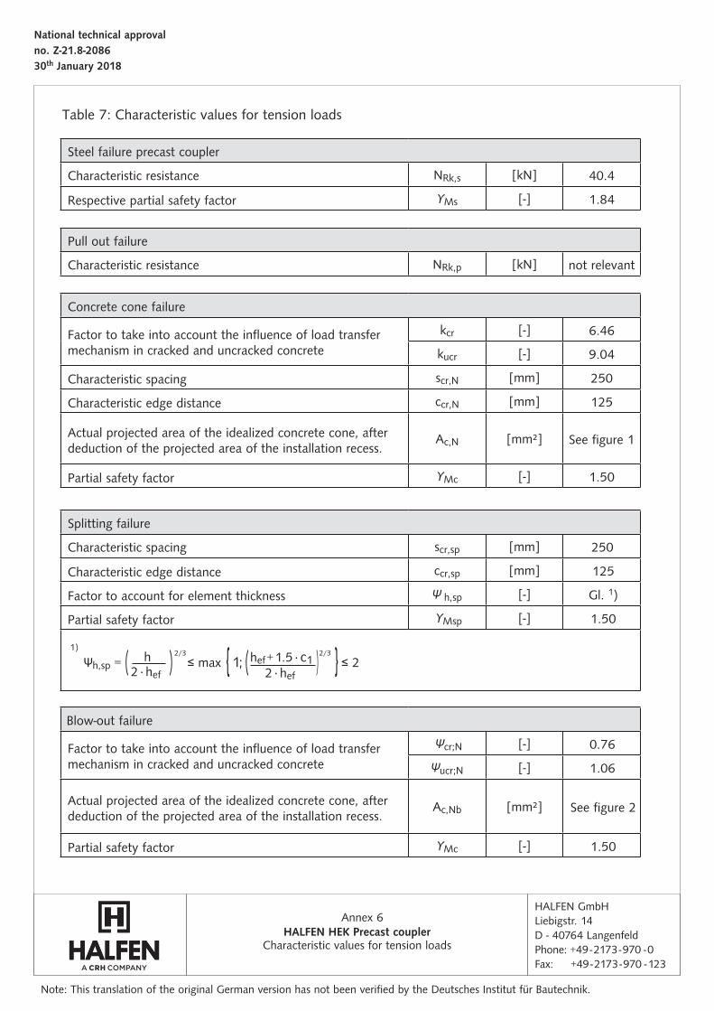
Table 7: Characteristic values for tension loads
Steel failure precast coupler
Characteristic resistance NRk,s [kN] 40.4
Respective partial safety factor ϒMs [-] 1.84
Pull out failure
Characteristic resistance NRk,p [kN] not relevant
Splitting failure
Characteristic spacing scr,sp [mm] 250
Characteristic edge distance ccr,sp [mm] 125
Factor to account for element thickness Ψ h,sp [-] Gl. 1)
Partial safety factor ϒMsp [-] 1.50
Blow-out failure
Factor to take into account the influence of load transfer mechanism in cracked and uncracked concrete
Ψcr;N [-] 0.76
Ψucr;N [-] 1.06
Actual projected area of the idealized concrete cone, after deduction of the projected area of the installation recess.
Ac,Nb [mm²] See figure 2
Partial safety factor ϒMc [-] 1.50
Concrete cone failure
Factor to take into account the influence of load transfer mechanism in cracked and uncracked concrete
kcr [-] 6.46
kucr [-] 9.04
Characteristic spacing scr,N [mm] 250
Characteristic edge distance ccr,N [mm] 125
Actual projected area of the idealized concrete cone, after deduction of the projected area of the installation recess.
Ac,N [mm²] See figure 1
Partial safety factor ϒMc [-] 1.50
HALFEN HEK Precast coupler
Ψh,sp = ( ) ≤ max { 1; ( ) } ≤ 21)
2/3 2/3hef + 1.5 ⋅ c12 ⋅ hef
h2 ⋅ hef
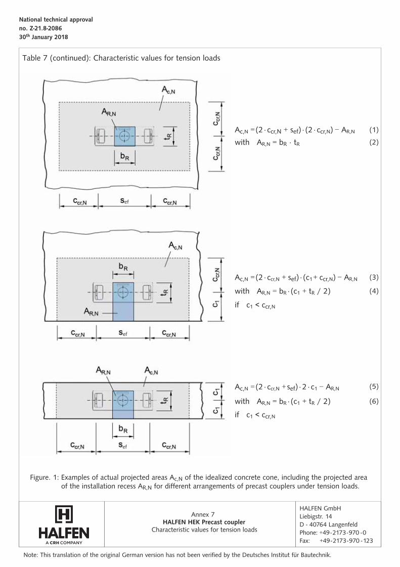
Table 7 (continued): Characteristic values for tension loads
HALFEN GmbHLiebigstr. 14D - 40764 LangenfeldPhone: +49 - 2173 - 970 - 0Fax: +49 - 2173 - 970 - 123
Annex
National technical approval no. Z-21.8-208630th January 2018
Characteristic values for tension loads
7
Note: This translation of the original German version has not been verifi ed by the Deutsches Institut für Bautechnik.
Figure. 1: Examples of actual projected areas Ac,N of the idealized concrete cone, including the projected area of the installation recess AR,N for diff erent arrangements of precast couplers under tension loads.
ef
ef
ef
HALFEN HEK Precast coupler
(3)Ac,N = (2 ⋅ ccr,N + sef) ⋅ (c1 + ccr,N) − AR,N
with AR,N = bR ⋅ (c1 + tR / 2)
if c1 < ccr,N
(4)
(1)Ac,N = (2 ⋅ ccr,N + sef) ⋅ (2 ⋅ ccr,N) − AR,N
with AR,N = bR ⋅ tR (2)
Ac,N = (2 ⋅ ccr,N + sef) ⋅ 2 ⋅ c1 − AR,N
with AR,N = bR ⋅ (c1 + tR / 2)
if c1 < ccr,N
(5)
(6)
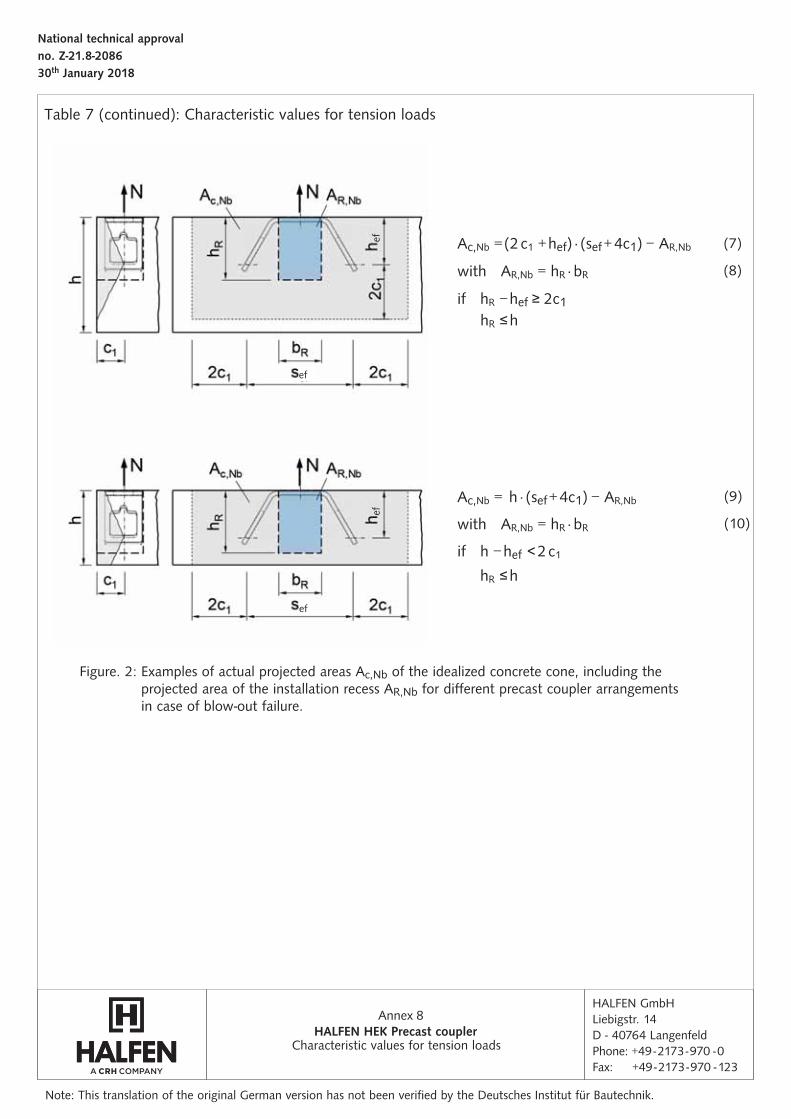
Table 7 (continued): Characteristic values for tension loads
HALFEN GmbHLiebigstr. 14D - 40764 LangenfeldPhone: +49 - 2173 - 970 - 0Fax: +49 - 2173 - 970 - 123
Annex
National technical approval no. Z-21.8-208630th January 2018
8
ef
efef
ef
Figure. 2: Examples of actual projected areas Ac,Nb of the idealized concrete cone, including the projected area of the installation recess AR,Nb for diff erent precast coupler arrangements in case of blow-out failure.
Note: This translation of the original German version has not been verifi ed by the Deutsches Institut für Bautechnik.
HALFEN HEK Precast coupler
(9)
(10)
(7)Ac,Nb = (2 c1 + hef) ⋅ (sef + 4c1) − AR,Nb
with AR,Nb = hR ⋅ bR
hR ≤ hif hR − hef ≥ 2c1
(8)
Ac,Nb = h ⋅ (sef + 4c1) − AR,Nb
with AR,Nb = hR ⋅ bR
if h − hef < 2 c1
hR ≤ h
Characteristic values for tension loads
HALFEN GmbHLiebigstr. 14D - 40764 LangenfeldPhone: +49 - 2173 - 970 - 0Fax: +49 - 2173 - 970 - 123
Annex
National technical approval no. Z-21.8-208630th January 2018
9
Note: This translation of the original German version has not been verifi ed by the Deutsches Institut für Bautechnik.
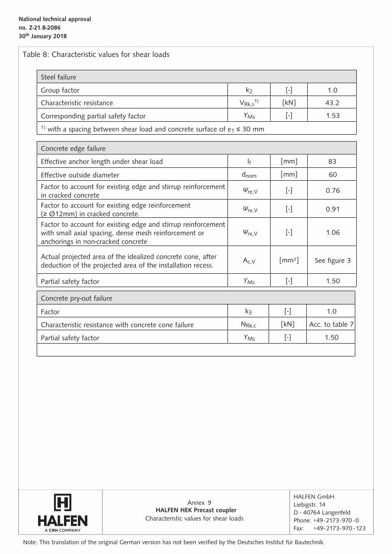
Characteristic values for shear loadsHALFEN HEK Precast coupler
Steel failure
Group factor k2 [-] 1.0
Characteristic resistance VRk,s1) [kN] 43.2
Corresponding partial safety factor ϒMs [-] 1.53
1) with a spacing between shear load and concrete surface of e1 ≤ 30 mm
Concrete pry-out failure
Factor k3 [-] 1.0
Characteristic resistance with concrete cone failure NRk,c [kN] Acc. to table 7
Partial safety factor ϒMc [-] 1.50
Concrete edge failure
Effective anchor length under shear load lf [mm] 83
Effective outside diameter dnom [mm] 60
Factor to account for existing edge and stirrup reinforcement in cracked concrete
Ψre,V [-] 0.76
Factor to account for existing edge reinforcement (≥ Ø12mm) in cracked concrete.
Ψre,V [-] 0.91
Factor to account for existing edge and stirrup reinforcement with small axial spacing, dense mesh reinforcement or anchorings in non-cracked concrete
Ψre,V [-] 1.06
Actual projected area of the idealized concrete cone, after deduction of the projected area of the installation recess.
Ac,V [mm²] See figure 3
Partial safety factor ϒMc [-] 1.50
Table 8: Characteristic values for shear loads
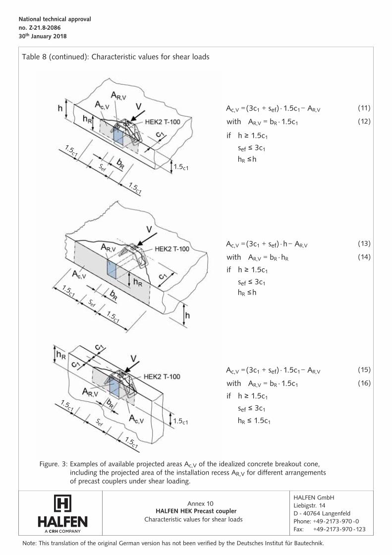
Table 8 (continued): Characteristic values for shear loads
HALFEN GmbHLiebigstr. 14D - 40764 LangenfeldPhone: +49 - 2173 - 970 - 0Fax: +49 - 2173 - 970 - 123
Annex
National technical approval no. Z-21.8-208630th January 2018
Characteristic values for shear loads
10
(11)
(13)
(15)
Note: This translation of the original German version has not been verifi ed by the Deutsches Institut für Bautechnik.
HALFEN HEK Precast coupler
Figure. 3: Examples of available projected areas Ac,V of the idealized concrete breakout cone, including the projected area of the installation recess AR,V for diff erent arrangements of precast couplers under shear loading.
1.5c1
1.5c1
1.5c1
1.5c1
1.5c1
1.5c1
1.5c1
1.5c1
(12)
(14)
(16)
with AR,V = bR ⋅ 1.5c1
with AR,V = bR ⋅ 1.5c1
with AR,V = bR ⋅ hR
if h ≥ 1.5c1
if h ≥ 1.5c1
if h ≥ 1.5c1
sef ≤ 3c1
sef ≤ 3c1
sef ≤ 3c1
hR ≤ h
hR ≤ 1.5c1
hR ≤ h
Ac,V = (3c1 + sef) ⋅ 1.5c1 − AR,V
Ac,V = (3c1 + sef) ⋅ 1.5c1 − AR,V
Ac,V = (3c1 + sef) ⋅ h − AR,V
Sef
Sef
Sef
HALFEN GmbHLiebigstr. 14D - 40764 LangenfeldPhone: +49 - 2173 - 970 - 0Fax: +49 - 2173 - 970 - 123
Annex
National technical approval no. Z-21.8-208630th January 2018
11
Note: This translation of the original German version has not been verifi ed by the Deutsches Institut für Bautechnik.
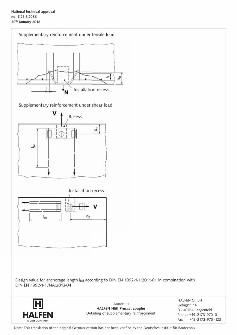
Detailing of supplementary reinforcementHALFEN HEK Precast coupler
Design value for anchorage length lbd according to DIN EN 1992-1-1:2011-01 in combination withDIN EN 1992-1-1/NA:2013-04
Installation recess
Installation recess
Supplementary reinforcement under shear load
Supplementary reinforcement under tensile load
Recess

www.dnvgl.com
NOTES REGARDING THIS CATALOGUETechnical and design changes reserved. The information in this publication is based on state-of-the-art technology at the time of publication. We reserve the right to make technical and design changes at any time. HALFEN GmbH shall not accept liability for the accuracy of the information in this publication or for any printing errors.
The HALFEN GmbH subsidiaries in Germany, France, the Netherlands, Austria, Poland, Switzerland and the Czech Republic are Quality Management certified according to ISO 9001:2015, Certificate no. 202384-2016-AQ-GER-DAkkS.
Austria HALFEN Gesellschaft m.b.H.Leonard-Bernstein-Str. 101220 Wien
Phone: +43 - 1 - 259 6770 E-Mail: [email protected]: www.halfen.at
Fax: +43 - 1 - 259 - 6770 99
Belgium / Luxembourg HALFEN N.V.Borkelstraat 1312900 Schoten
Phone: +32 - 3 - 658 07 20E-Mail: [email protected]: www.halfen.be
Fax: +32 - 3 - 658 15 33
China HALFEN Construction Accessories Distribution Co.Ltd.Room 601 Tower D, Vantone CentreNo. A6 Chao Yang Men Wai StreetChaoyang District Beijing · P.R. China 100020
Phone: +86 - 10 5907 3200E-Mail: [email protected]: www.halfen.cn
Fax: +86 - 10 5907 3218
Czech Republic HALFEN s.r.o.Business Center ŠafránkovaŠafránkova 1238/1155 00 Praha 5
Phone: +420 - 311 - 690 060E-Mail: [email protected]: www.halfen.cz
Fax: +420 - 235 - 314 308
France HALFEN S.A.S.18, rue Goubet75019 Paris
Phone: +33 - 1 - 445231 00E-Mail: [email protected]: www.halfen.fr
Fax: +33 - 1 - 445231 52
Germany HALFEN Vertriebsgesellschaft mbHLiebigstr. 14 40764 Langenfeld
Phone: +49 - 2173 - 970 - 0E-Mail: [email protected]: www.halfen.de
Fax: +49 - 2173 - 970 225
Italy HALFEN S.r.l. Soc. UnipersonaleVia F.lli Bronzetti N° 2824124 Bergamo
Phone: +39 - 035 - 0760711E-Mail: [email protected]: www.halfen.it
Fax: +39 - 035 - 0760799
Netherlands HALFEN b.v.Oostermaat 37623 CS Borne
Phone: +31 - 74-267 14 49E-Mail: [email protected]: www.halfen.nl
Fax: +31 - 74-267 26 59
Norway HALFEN ASPostboks 20804095 Stavanger
Phone: +47 - 51 82 34 00E-Mail: [email protected]: www.halfen.no
Poland HALFEN Sp. z o.o.Ul. Obornicka 28760-691 Poznan
Phone: +48 - 61 - 622 14 14E-Mail: [email protected]: www.halfen.pl
Fax: +48 - 61 - 622 14 15
Spain HALFEN SpainPLAKABETON S.L.Polígono Industrial Santa Ana c/ Ignacio Zuloaga 2028522 Rivas-Vaciamadrid
Phone: +34 916 669 181E-Mail: [email protected]: www.halfen.es
Fax: +34 916 669 661
Sweden Halfen ABVädursgatan 5412 50 Göteborg
Phone: +46 - 31 - 98 58 00E-Mail: [email protected]: www.halfen.se
Fax: +46 - 31 - 98 58 01
Switzerland HALFEN Swiss AGHertistrasse 25 8304 Wallisellen
Phone: +41 - 44 - 849 78 78E-Mail: [email protected]: www.halfen.ch
Fax: +41 - 44 - 849 78 79
United Kingdom /Ireland
HALFEN Ltd.A1/A2 Portland CloseHoughton Regis LU5 5AW
Phone: +44 - 1582 - 47 03 00E-Mail: [email protected]: www.halfen.co.uk
Fax: +44 - 1582 - 47 03 04
United States of America HALFEN USA Inc. PO Box 18687 San Antonio TX 78218
Phone: +1 800.423.91 40E-Mail: [email protected]: www.halfenusa.com
Fax: +1 877.683.4910
For countries not listed HALFEN International
HALFEN International GmbHLiebigstr. 14 40764 Langenfeld / Germany
Phone: +49 - 2173 - 970 - 0 E-Mail: [email protected]: www.halfen.com
Fax: +49 - 2173 - 970 - 849
CONTACT HALFEN WORLDWIDE
HALFEN is represented by subsidiaries in the following countries, please contact us!

For further information please contact: www.halfen.com
© 2
018
HA
LFEN
Gm
bH, G
erm
any
appl
ies
also
to
copy
ing
in e
xtra
cts.
R -
293-
E - 0
2/18
PD
F 0
2/18