HALFEN SHEAR DOWEL SYSTEM
30
HALFEN SHEAR DOWEL SYSTEM CONCRETE Z_CRET 03/16-E
Transcript of HALFEN SHEAR DOWEL SYSTEM

HALFEN SHEAR DOWEL SYSTEM
CONCRETE
Z_CRET 03/16-E

National technical approval
Approval number:
Z-15.7-253
Applicant:
F. J. Aschwanden AG
Grenzstrasse 24
3250 Lyss
SWITZERLAND
Subject of approval:
Deutsches
Institut
für
Bautechnik OIEt
Zulassungsstelle für Bauprodukte und Bauarten
Bautechnisches Prüfamt
Eine vom Bund und den Ländern
gemeinsam getragene Anstalt des öffentlichen Rechts
Mitglied der EOTA, der UEAtc und derWFTAO
Date: Reference:
11 March 2016 127-1.15.7-45/15
Validity
from: 14 March 2016
to: 14 March 2021
CRET shear load connector in accordance with DIN 1045-1 and DIN EN 1992-1-1
The subject of approval named above is herewith granted a national technical approval (allgemeine
bauaufsichtliche Zulassung).
This national technical approval contains nine pages and 18 annexes. This national technical approval
replaces national technical approval no. Z-15.7-253 of 30 April 2013. The subject of approval was
granted the first national technical approval on 28 June 2006.
Translation authorised by DIBt
DIBt I Kolonnenstraße 30 BI D-10829 Berlin I Tel.: +493078730-01 Fax: +493078730-3201 E-Mail:[email protected]

National technical approval
(allgemeine bauaufsichtliche Zulassung)
No. Z-15. 7-253
GENERAL PROVISIONS
Deutsches Institut
für Bautechnik DIEt
Page 2 of 9 111 March 2016
1 With the national technical approval, the fitness for use and the applicability of the subject of approval in accordance with the Building Codes of the federal states (Landesbauordnungen) have been verified.
2 lf in the national technical approval requirements are made concerning the special expertise and experience of persons entrusted with the manufacture of construction products and types of construction in accordance with the provisions of the relevant federal state following Section 17 Sub-section 5 of the Model Building Code (Musterbauordnung), it shall be noted that this expertise and experience can also be proven by equivalent verifications from other Member States of the European Union. lf necessary, this also applies to equivalent verifications presented within the framework of the Agreement on the European Economic Area (EEA) or other bilateral agreements.
3 The national technical approval does not replace the permits, approvals and certificates prescribed by law for carrying out building projects.
4 The national technical approval is granted without prejudice to the rights of third parties, in particular private property rights.
5 Notwithstanding further provisions in the "Special Provisions", manufacturers and distributors of the subject of approval shall make copies of the national technical approval available to the user and point out that the national technical approval must be available at the place of use. Upon request, copies of the national technical approval shall be placed at the disposal of the authorities involved.
6 The national technical approval shall be reproduced in full only. Partial publication requires the consent of Deutsches Institut für Bautechnik. Texts and drawings in promotional materials shall not contradict the national technical approval. In the event of a discrepancy between the German original of the national technical approval and this authorised translation, the German version shall prevail.
7 The national technical approval is granted until revoked. The prov1s1ons of the national technical approval can subsequently be supplemented and amended, in particular if this is required by new technical findings.
Translation authorised by DIBt
National technical approval
(allgemeine bauaufsichttiche Zulassung)
No. Z-15.7-253
11 SPECIAL PROVISIONS
1 Subject of approval and field of application
Deutsches
Institut
für
Bautechnik DIBt
Page 3 of 9111 March 2016
The Aschwanden shear load connector CRET SERIES 100 (see Annex 1) is a connecting element between members made of reinforced concrete in accordance with DIN 1045-1:2008-08 or DIN EN 1992-1-1:2011-01 and is used for the planned transmission of shear loads. Application is limited to normal weight concrete (density between 2,000kg/m3
to 2,600 kg/m3) of strength classes C20/25 to C50/60.
The shear load connector may be used as a positive connecting element between reinforced concrete members, which fulfil the conditions for limiting the deflection in accordance with DIN 1045-1, Clause 11.3.2, or in accordance with DIN EN 1992-1-1, Clause 7.4.2, taking into consideration DIN EN 1992-1-1/NA:2013-04, NCI to 7.4.2(2), under predominantly static loads.
The permissible ambient conditions are based on the exposure classes (DIN 1045-1, Table 3, or DIN EN 1992-1-1, Table 4.1) as weil as on the corrosion resistance classes of the steels used in accordance with national technical approval no. Z-30.3-6.
The shear load connector consists of a dowel part and a corresponding sleeve part, which both transfer the loads into the concrete via an anchor body. The anchor body consists of a front plate which is chamfered in the concrete, which is reinforced with screws in the direction of loading to improve the load transfer into the concrete.
The shear load connectors are approved in the types CRET SERIES 100 and CRET SERIES 100 V 122, 124, 126, 128, 130, 132, 134, 136, 138 and 140.
For type CRET SERIES 100, the sleeve is the round counterpart to the shear load connector so that movements are only possible in the direction of the longitudinal axes of the shear load connector.
For type CRET SERIES 100 V, the sleeve part is formed as a rectangular sleeve where the dowel is housed in a correspondingly wider rectangular tube. This ailows additional horizontal movement perpendicular to the longitudinal axis of the dowel.
The joint width between the members to be connected shall not exceed 60 mm.
2 Provisions for the construction product
2.1 Properties and composition
The shear load connector shall comply with the specifications and drawings given in the annexes.
The outer dimensions of the shear load connectors are specified in Annexes 1 to 3.
The shear load connector consists of the following materials:
Anchor body Stainless steel with material number 1.4404 or 1.4362 in accordance with national technical approval no. Z-30.3-6 with minimum corrosion resistance class III and strength class S 275
Anchor rods (threaded Stainless steel with material number 1.4401 or 1.4362 in bars and nuts) accordance with national technical approval no. Z-30.3-6 with
minimum corrosion resistance class III and strength class 70
Dowel Stainless steel with material number 1.4462 of strength class S 690 as weil as properties as stated in the data sheet deposited with DIBt
The edges of the sleeve opening shall be free of burrs.
Translation authorised by DIBt

National technical approval
Deutsches
Institut
für
Bautechnik OIBt
(allgemeine bauaufsichtliche Zulassung) Page 4 of 9111 March 2016
No. Z-15.7-253
The material properties, dimensions, tolerances and design details not given in this national technical approval shall comply with the information deposited with Deutsches Institut für Bautechnik, the certification body and the external surveillance body.
2.2 Manufacture and marking
2.2.1 Manufacture
DIN EN 1090-1 and DIN EN 1090-2 apply to welding. For the execution of the welding work, only welders shall be used who are certified in accordance with DIN EN 287-1.
The welding company is obliged to ensure that the welding work meets the quality requirements for the product, using work samples if necessary. In addition, the specifications of national technical approval no. Z-30.3-6 "Products, fasteners and members made from stainless steels" apply.
The surfaces shall be clean and smooth. Tempering colours shall be removed.
2.2.2 Marking
The manufacturer shall affix the national conformity mark ( O-Zeichen) to each packaging unit of the shear load connector in accordance with the Conformity Marking Ordinances ( Obereinstimmungszeichen-Verordnungen) of the federal states.
The mark shall only be applied if the requirements given in Section 2.3 "Attestation of conformity" are met. In addition, the mark shall include at least the following information:
- the designation of the subject of approval,
- type designation.
The manufacturer shall supply an installation manual with every delivery.
2.3 Attestation of conformity
2.3.1 General
The attestation of conformity of the construction product with the provisions of this national technical approval shall be issued for every manufacturing plant in the form of a certificate of conformity based on factory production control and regular external surveillance, including initial type-testing of the construction product, in accordance with the following provisions.
To issue the certificate of conformity and for external surveillance, including the associated product testing to be carried out in the process, the manufacturer of the construction product shall use a certification body recognised for the certification of anchor channels (no. 10.4) and an inspection body recognised for the monitoring of anchor channels (no. 10.4).
The declaration that a certificate of conformity has been granted shall be submitted by the manufacturer through marking of the construction products with the national conformity mark (O-Zeichen) including statement of the intended use.
The certification body shall send a copy of the certificate of conformity issued by it to Deutsches Institut für Bautechnik.
A copy of the initial type-testing report shall also be sent to Deutsches Institut für Bautechnik.
Translation authorised by DIBt

National technical approval
Deutsches Institut
für Bautechnik DIEt
(allgemeine bauaufsichtliche Zulassung) Page 5 of 9111 March 2016
No. Z-15.7-253
2.3.2 Factory production control
A factory production control system shall be set up and implemented in each manufacturing plant. Factory production control is understood to be continuous surveillance of production by the manufacturer to ensure that the manufactured construction products satisfy the provisions of this national technical approval.
The factory production control shall at least include the measures laid down in the test plan as weil as the measures listed below. The test plan is deposited with Deutsches Institut für Bautechnik and the body consulted regarding the external surveillance.
• Verification of the starting material and the components:
Only materials for which the verification of conformity in accordance with the applicablestandards and approvals has been provided shall be used for the shear load connector.
For stainless steel, national technical approval no. Z-30.3-6 applies.
For material 1.4462 for use as a dowel cross-section, the mechanical properties shall beverified in accordance with the data sheet deposited with Deutsches Institut fürBautechnik and the external surveillance body by a specific inspection certificate"type 3.1" in accordance with DIN EN 10204.
• Verifications and tests to be carried out on the finished construction product:
The member dimensions of the shear load connectors shall be checked for each partand compared with the requirements of the test plan deposited with Deutsches Institutfür Bautechnik and the external surveillance body. The surface quality must be checkedand compared with the requirements.
The results of factory production control shall be recorded and evaluated. In addition to the information specified in the test plan, the records shall include at least the following information:
• designation of the construction product or the starting material and the components
• type of check or test• date of manufacture and testing of the construction product or the starting material or the
components• results of the checks and tests as weil as, if applicable, comparison with requirements
• signature of the person responsible for factory production control.
The records shall be kept for at least five years and submitted to the inspection body used for external surveillance. They shall be submitted to Deutsches Institut für Bautechnik and the competent supreme building authority upon request.
lf the test result is unsatisfactory, the manufacturer shall immediately take the necessary measures to resolve the defect. Construction products which do not meet the requirements shall be handled in such a way that they cannot be confused with compliant products.
After the defect has been remedied, the relevant test shall be repeated immediately - where technically feasible and necessary to show that the defect has been eliminated.
2.3.3 Initial type-testing of the construction product
As part of the initial type-testing, the following shall be tested:
- proper surface treatment of the starting material
- proper execution of the welding seams for all shear load connector classes
Translation authorised by DIBt

National technical approval
(allgemeine bauaufsicht/iche Zulassung)
No. Z-15.7-253
Deutsches
Institut
für
Bautechnik
1
OIBt
Page 6 of 9 111 March 2016
- compliance with the dimensions specified in the approval for the shear load connectorclasses as weil as means to ensure the dimensional accuracy.
2.3.4 External surveillance
The factory production control system at each manufacturing plant shall be inspected regularly, at least twice a year, by means of external surveillance.
An initial type-testing of the shear load connectors, in particular the welding seams and the surfaces, shall be carried out within the scope of external surveillance. Samples for random testing shall also to be taken and checked as specified in the test plan. The values of the starting material shall be checked in accordance with the data sheet.
Sampling and testing shall be the responsibility of the recognised inspection body.
The results of certification and external surveillance shall be kept for at least five years. They shall be presented by the certification or inspection body to Deutsches Institut für Bautechnik upon request.
The results of certification and external surveillance shall be kept for at least five years. The certification body or inspection body shall present them to Deutsches Institut für Bautechnik and the competent supreme building authority upon request.
3 Provisions for planning and design
3.1 General
Either DIN 1045-1 or DIN EN 1992-1-1 applies, unless otherwise specified below. Mixing the two Technical Building Rules is not permitted. DIN EN 1992-1-1 always applies in conjunction with DIN EN 1992-1-1/NA.
The transmission (distribution and absorption) of the forces transmitted by the shear load connector to the adjacent members shall be verified for each individual case.
For the ultimate limit state, verification shall be provided in accordance with Annex 6 and Section 3.2.
Installation of the shear load connectors in areas which are only subject to tensile stress is excluded.
The shear load connector of type CRET SERI ES 100 is intended for the connection of members in cases where horizontal loads perpendicular to the axis of the shear load connector do not arise, for example as a result of different thermal deformations.
lf horizontal displacements are possible in the direction of the shear load connector axes and perpendicular to same, shear load connectors of type CRET SERIES 100 V shall be used.
Shear load connectors shall only be installed in slabs with straight edges. In all other cases, sufficient movement shall be verified for every shear load connector.
lf the shear load connectors are installed at an angle, sufficient movement shall be verified.
The longitudinal reinforcement Asy at the slab edge may be determined with the assumption
of a continuous edge beam, with spans corresponding to the spacing of the shear load
connectors. The distribution reinforcement Asy which is shown in Annex 4 may be used for
this purpose.
The reinforcing steel bars B500B in accordance with DIN 488-1 shall be used for in-situ reinforcement.
3.2 Ultimate lim it states
3.2.1 Steel failure
The design resistance values for the shear load connector cross sections are specified in Annex 13 depending on the joint width. A joint width f = 20 mm, f = 30 mm, f = 40 mm, f = 50 mm, f = 60 mm shall be used for the calculation.
Translation authorised by DIBt

Deutsches
Institut
für
Bautechnik OIBt
National technical approval
(allgemeine bauaufsichtliche Zulassung) Page 7 of 9111 March 2016
No. Z-15. 7-253
The design resistance values only apply for the joint widths specified (Annex 13). lf there is a possibility that the joint widths used for the calculation may be exceeded, the design resistance values of the next larger joint width shall be used.
3.2.2 Punching shear verification
The design value of the resistance against punching shear VRd ,c for the individual dowel is specified in Annexes 14 to 18. An influence on edges or other punching shear cones is excluded (see Annex 7, Figure 2 top illustration).
The design resistances specified in Annexes 14 to 18 only apply under the following boundary conditions:
Installation of shear load connector in good bonding areas (dowel and in-situ reinforcement)
Spacing of shear load connectors (dowel centre) a � 3 · dm + lc1 (see Annex 7)
Member dimensions, reinforcement diameter and layout of reinforcement (spacing, concrete coverage) in accordance with Annexes 8 to 12
For different installation conditions, the punching shear verification in accordance with Annex 7 applies. The mutual interference of the punching shear cones shall be taken into account, where applicable.
The implementation of the critical section and the specification of the spacing between the shear load connectors as weil as minimum edge distances shall be selected in accordance with Annex 7. Clause 10.5.6 of DIN 1045-1 or Clause 6.4.5 of DIN EN 1992-1-1 together with DIN EN 1992-1-1/NA, NCI to 6.4.5 shall be taken into account.
The placement of a punching shear reinforcement is not permitted.
The radii of the critical section start on a level with the stirrups which are positioned directly beside the shear load connectors (Annex 7, Figure 2).
The reinforcement Asx and Asy shall be anchored with min lb,net in accordance with Annex 5. On slab corners or narrow slab strips, it must be anchored using stirrups with the same diameter.
The layout of the suspension reinforcement Asx and shear reinforcement Asy is specified in Annex 4.
3.2.4 Concrete edge failure
The design value of the resistance against concrete edge failure VRd,c is specified in Annexes 14 to 18.
The design resistances specified in Annexes 14 to 18 only apply under the following boundary conditions:
Installation of shear load connector in good bonding areas (dowel and in-situ reinforcement)
Spacing of shear load connectors (dowel centre) a � 3 (c1 + f/2) (see Annex 8)
Member dimensions, reinforcement diameter and layout of reinforcement (spacing, concrete coverage) in accordance with Annexes 8 to 12
The first suspension stirrups Asx,1 shall be placed directly on the anchor body of the shear load connector.
For the number nsurrups of the suspension stirrups Asx,1 or Asx,2 in the calculated failure cone, the condition 3 ::;; nsurrups::;; 8 shall be adhered to.
The diameter of the rear-suspended reinforcement Asx1 is:
ds ::;; 16 mm for h < 30 cm
ds::;; 20 mm for
ds::;; 25 mm for
30 cm ::;; h ::;; 40 cm
40 cm< h
Translation authorised by DIBt

National technical approval
Deutsches Institut
für Bautechnik DIBt
(allgemeine bauaufsichtliche Zulassung) Page 8 of 9 l 11 March 2016
No. Z-15. 7-253
The ratio slab thickness to shear load connector diameter h/D 2:: 7 shall be adhered to.
For the ratio of the diameters dsy of the longitudinal reinforcement Asy
to dsx of the stirrups Asx,1, dsy / dsy 2:: 1 shall apply.
3.2.5 Consideration of frictional forces
For the dimensioning of the shear load connector cross section and the in-situ reinforcement,
frictional forces due to the reduction of design resistances by factor fr1 shall be taken into consideration as follows: - For the dimensioning of the steel load-bearing capacity (dowel cross section), the
reduction has been taken into account in the tables in Annex 13.- For the verification of the concrete load-bearing capacity, the reduction of the load
bearing capacity of reinforcement Asx1 for concrete edge failure VRd ,c has been taken
into account by factor fr1 = 0.9 in the tables in Annexes 14 to 18.
3.3 Serviceability
3.3.1 Limitation of crack widths
The verification of crack widths of the slab edge beam shall be carried out in accordance with DIN 1045-1, Clause 11.2 or DIN EN 1992-1-1, 7.3, taking into consideration the corresponding clauses of DIN EN 1992-1-1/NA.
3.3.2 Limitation of deformation
As regards shear force, the shear load connector may be used as a positive connecting element between reinforced concrete members, which fulfil the conditions for limiling the deflection in accordance with DIN 1045-1, Clause 11.3.2 or in accordance with DIN EN 1992-1-1, 7.4.2 taking inlo consideration DIN EN 1992-1-1/NA, NCI to 7.4.2(2).
4 Provisions for execution
The suriaces of the sleeve and dowel have been treated in the factory to minimise friction. Any in-situ changes to the suriace which increase surface roughness shall not be permitted.
During the installation of the shear load connectors, the distances from the top and bottom edges of the members to be connected to the centre of the shear load connector shall not be below the minimum distances hmin/2.
Great care shall be taken to ensure that angular deviations do not occur between adjacent shear load connectors and the specified joint widths are adhered to.
When installing the sleeves for the type which allows lateral movement, care shall be taken that all sleeves in a joint area are installed in parallel and are precisely aligned with each other in relation to the direction of the lateral movement. This can, for example, be implemented by attaching the sleeves to a continuous reinforcing rod or a corresponding template.
The following standards, approvals and references are referred to in this national technical approval:
- DIN 488-1 :2009-08
- DIN1045-1:2008-08
- DIN EN 1090-1:2012-02
Reinforcing steels - Part 1: Grades, properties, marking
Concrete, reinforced and prestressed concrete structures -Part 1: Design and construction
Execution of steel structures and aluminium structures - Part 1: Requirements for conformity assessment of structural components, Germ an version EN 1090-1 :2009 + A 1 :2011
Translation authorised by DIBt
National technical approval
Deutsches
Institut
für
Bautechnik OIBt
(allgemeine bauaufsichtliche Zulassung) Page 9 of 9 111 March 2016
No. 2-15.7-253
- DIN EN 1090-2:2011-10
- DIN EN 287-1:2006-06
- DIN EN 1992-1-1:2011-01
DIN EN 1992-1-1/NA:2013-04
- DIN EN 10204:2005-01
- Approval no. Z-30.3-6
Execution of steel structures and aluminium structures - Part 2: Technical requirements for steel structures, German version EN 1090-2:2008 + A1 :2011
Qualification testing of welders - Fusion welding - Part 1: Steels; German version EN 287-1 :2004 + A2:2006
Eurocode 2: Design of concrete structures - Part 1-1: General
design rules and rules for buildings; German version
EN 1992-1-1:2004+AC:2010 and National Annex - Nationally determined parameters -Eurocode 2: Design of concrete structures - Part 1-1: General
rules and rules for buildings
Metallic products - Types of inspection documents; German version EN 10204:2004
Products, fasteners and structural components made of stainless steels, dated 22 April 2014
- The data sheet is deposited with Deutsches Institut für Bautechnik and the body consultedregarding the external surveillance.
- The test plan is deposited with Deutsches Institut für Bautechnik and the body consulted regardingthe external surveillance.
Andreas Kummerow
Head of Section
Drawn up by
Translation authorised by DIBt

National technical approval
(allgemeine bauaufsichtliche Zulassung)
No. 2-15.7-253 of 11 March 2016
View
---- -·-·---
(_) ..
-- ·➔--·-. -----·-·
0
...0
g
f
1
-- --
-·- -·-'
J_
--·- -1--
- .
�·--·-·- +-·-f·
'-
a b
CRET 122/122V 302 180
CRET 124/124V 341 192
CRET 126/126V 365 240
CRET 128/128V 388 215
CRET 130/130V 405 225
CRET 132/132V 427 235
CRET 134/134V 450 246
CRET 136/136V 474 258
CRET 138/138V 498 270
CRET 140/140V 520 280
Dimensions in (mm)
-·-·---
C
108
133
145
155
160
170
180
190
200
210
Deutsches Institut
für Bautechnik OIBt
w Tog view
I-$ i
�et
I-$ 1 �
--
e f g 0
70 80 140 22
76 90 160 24
82 100 180 26
88 110 200 28
94 125 220 30
100 145 240 32
106 160 260 34
112 175 280 36
118 190 300 38
124 200 310 40
Models: Dowel CRET 122/122V; 124/124V; 126/126V; 128/128V; 130/130V; 132/132V; 134/134V; 136/136V; 138/138V; 140/140V
CRET shear load connector in accordance with DIN 1045-1 and DIN EN 1992-1-1
Dowel dimensions Annex 1
Translation authorised by DIBt

National technical approval
(allgemeine bauaufsichtfiche Zulassung)
No. Z-15.7-253 of 11 March 2016
u
0
_o
--·- +-+ LJ \..
g
f
-- !
i ! ' 7 .. -·-·-·- ·--'--· ·-·-·-·-·I --·�· -·-·-·-1
i! '
i i i
_, \...
r i -, --+ --·-- -+- ---- +--
L : J i i i i ii i 'ii i
.......1-! '! 1
Deutsches
Institut
für
Bautechnik
e
!...;:= i
-·@-1-@)-l
� I
-·-· __ ,_j ____ ----i
•'-V•
-@- i -�-1 ! '
i i i ! 1 ! : i i
-r-1
7t PE pipe / protection cap
�-
a b C e g
CRET 122 180 72 108 100 80 140
CRET 124 192 59 133 106 90 160
CRET 126 204 59 145 112 100 180
CRET 128 215 60 155 118 110 200
CRET 130 225 65 160 124 125 220
CRET 132 235 65 170 130 145 240
CRET 134 246 66 180 136 160 260
CRET 136 258 68 190 142 175 280
CRET 138 270 70 200 148 190 300
CRET 140 280 70 210 154 200 310
Dimensions in (mm)
Models: Sleeve CRET 122; 124; 126; 128; 130; 132; 134; 136; 138; 140
CRET shear load connector in accordance with DIN 1045-1 and DIN EN 1992-1-1
Sleeve dimensions - movable in longitudinal direction
Translation authorised by DIBt
OIBt
Top view
n 0
70 25.4
76 28
82 30
88 32
94 34
100 36
106 38
112 40
118 42
124 44
Annex 2

National technical approval
(allgemeine bauaufsichtliche Zulassung)
No. Z-15.7-253 of 11 March 2016
g
f
View
! !
l r,. r 1
-·-·- +---� -·-·-· . ·-·-!-·-· .LJ l 1
1 -· 1
r i
--+ ·-·-·-· ·-·,·-·
0 l 1
! i
i i
__o
i i
! 1 i
� !
!
, r -·-·-· +-·+ w
- -
n ·-·-·-· +---
J
L
' l !
-$ -·-·-·-
-@ 1
Deutsches Institut
für Bautechnik
e
n
1 i !
- ! -
0 0 ·- -
l $-
�-
1
ill LJ
a b C e f g n
CRET 122V 181.5 73.5 108 125 80 140 95
CRET 124V 193.5 60.5 133 133 90 160 103
CRET 126V 204 59 145 132 100 180 102
CRET 128V 217 62 155 146 110 200 116
CRET 130V 225 65 160 155 125 220 125
CRET 132V 235 65 170 154 145 240 124
CRET 134V 248 68 180 168 160 260 138
CRET 136V 258 68 190 172 175 280 142
CRET 138V 270 70 200 176 190 300 146
CRET 140V 281.5 71.5 210 190 200 310 160
Dimensions in (mm)
Models: Sleeve CRET122V; 124V; 126V; 128V; 130V; 132V; 134V; 136V; 138V; 140V
CRET shear load connector in accordance with DIN 1045-1 and DIN EN 1992-1-1
Sleeve dimensions - movable in a longitudinal and transverse direction -
Translation authorised by DIBt
OIBt
Tor2 view
' 1 ;
0 q
26 50
28 55
30 50
32 60
34 65
36 60
38 70
40 70
42 70
44 75
Annex 3

National technical approval
(allgemeine bauaufsichtliche Zulassung)
No. Z-15.7-253 of 11 March 2016
View
1
1
1 1
� ./
1
ev.n ev.n
A SX1e
..i.. ..i..
Jlil" r,ir r-,, Ulr�-1
/ d ii../
.1 •• "t"
33°
l,;:; 1��2
bl2
Deutsches Institut
für Bautechnik OIBt
/d, /ld,,
/ / ✓ � 1
1
.... � 4-1
' 1
1 '- ......
33°
\_1
Crack path
ÄSXz
E
lc/2 Concrete edge failur e
111
1
111 1 1
Top view
�- -- --�---+-�--�-
� �
◄ ,
1 �
Section
"
..c::
.,i-...... ... ... ...
1-- - . --•,.. ,,. ,,. ,.. ,..
E
ex,1 ex,n ex,n ex,n , { x,2
Asy -
-- -- 1.. 11
1
1
1
- 1
1
1X 1t 1
1
1
1
1
Bild 1: Designations of the position of the reinforcement (for description of the designations, see Annex 5)
CRET shear load connector in accordance with DIN 1045-1 and DIN EN 1992-1-1
Illustration of position of reinforcement Annex 4
Translation authorised by DIBt

National technical approval
(allgemeine bauaufsichtliche Zulassung)
No. Z-15.7-253 of 11 March 2016
Description of designations selected in Annex 4, Figure 1:
Deutsches Institut
für Bautechnik OIBt
ld2
ld2
ld2
lc4/2
ey,n
=
=
=
=
=
Distance between symmetry axis of dowel and first stirrup reinforcement (symmetry axis)
Distance between symmetry axis of dowel and second stirrup reinforcement (symmetry axis)
Distance between symmetry axis of dowel and third stirrup reinforcement (symmetry axis)
Distance between symmetry axis of dowel and fourth stirrup reinforcement (symmetry axis)
Distance between stirrup reinforcements (symmetry axis, from 5th stirrup onwards)
ex,1 = Distance between 1st longitudinal reinforcement (symmetry axis, ascending numbering from concrete edge) and axis of 2nd longitudinal reinforcement
ex,2 = Distance between 2nd longitudinal reinforcement (symmetry axis, ascending numbering from concrete edge) and axis of 3rd longitudinal reinforcement
ex,n = Distance between additional longitudinal reinforcement rods (symmetry axis)
d5 = Rod diameter of stirrup reinforcement
d51 = Rod diameter of longitudinal reinforcement
Asx,1 = Stirrup reinforcement which is located inside the concrete edge failure cone and is anchored outside of the concrete edge failure cone with min lb,net-
Asx,2 = Stirrup reinforcement which is located outside the concrete edge failure cone, but inside the critical section (punching shear verification) and is anchored outside the punching shear cone with min lb,net•
Asy = Longitudinal reinforcement in Y-direction which is located inside the critical section (punching shear verification) and which is anchored outside the punching shear cone with min lb,net·
CRET shear load connector in accordance with DIN 1045-1 and DIN EN 1992-1-1
Illustration of position of reinforcement
Translation authorised by DIBt
Annex 5

National technical approval
(allgemeine bauaufsichtliche Zulassung)
No. Z-15.7-253 of 11 March 2016
Verifications required
With
Deutsches
Institut
für
Bautechnik
( 1)
OIBt
VRct
,s(Schoodcm > Design value of steel load-bearing capacity of dowel in accordance with Table 7 and Table 8
VRct c Design value of the transferable load within the rear suspended reinforcement (concrete edge failure) in accordance with Table 9 to Table 14
VRct,ct Design value of the transferable load outside of the rear suspended reinforcement (punching shear) in accordance with Table 9 to Table 14
CRET shear load connector in accordance with DIN 1045-1 and DIN EN 1992-1-1
Verifications Annex 6
Translation authorised by DI Bt

National technical approval
(allgemeine bauaufsichtliche Zulassung)
No. Z-15.7-253 of 11 March 2016
Punching shear verification
Verification outside of the rear suspended reinforcement in accordance with DIN 1045-1:2008-08; Clause 10.5.4
V Rd,ct = [ 0,14 · 111 · K · (1 00 · Pi · fck )i-] · dm · Ußc�t
where: 11,
K
= 1.0 for standard concrete
= 1+ ✓200<20dm -
Deutsches
Institut
für
Bautechnik OIBt
P1 =
P1 =
Average degree of longitudinal reinforcement within the section being considered with Asx and Asy
/,---{� 0,4 · fcd !(f
}d · 0,85) v Pix · Piy � 0,02
fck
dm
dm
Ucril
ßo
ßo
P1x
P1y
= = = =
Characteristic cylinder strength of the concrete, DIN 1045-1 , Table 9 Average effective depth [mm] (dx + dv)/2 Circumference of section of punching shear cone being considered, in accordance with Figure 2
= Coefficient for consideration of non-axially symmetric shear force distribution
=
=
=
1.4
Asx dm ·by
With by: area of reinforcement Asx
Asy dm ·bx
with bx: area of reinforcement Asy
1 I
e
[
i /,-----------,,/ Cri:cal section 'O
1 / \ 1
u')_ t / ..-\
1 "; : / \ l J 1 ' U IU t 1
1 i i 1
l 1,5dm 1��1
Critical section
-,--------------------------·/-------i-·
i [ i /✓.,.,-------------------- ---,,,,\ i � l / n�n \
1
J i ! 0 0 0 0
! i 1
In the formulas and figure 2 on this page, the comma is used as the decimal marker.
Figure 2: Section of punching shear cone
CRET shear load connector in accordance with DIN 1045-1 and DIN EN 1992-1-1
Punching shear verification Annex 7
Translation authorised by DIBt

National technical approval
(allgemeine bauaufsichtliche Zulassung)
No. Z-15. 7-253 of 11 March 2016
Deutsches Institut
für Bautechnik UIBt
Concrete edge failure Rod spacings, to which the design values of Table 9 to Table 14 apply:
Rules for the reinforcement layouts (Annexes 8 - 12, Table 1 to Table 6):
lc1/2 � n + 11.5 mm+ d5/2 lc2l2 � S1 + lc1 l2 + d5
lc3/2 � Sz + lcz/2 + d5
lc4/2 � S3 + lc3/2 + ds
where:
Thickness of member h :s; 300 mm S2,3
Thickness of member h > 300 mm
S1 � max (20 mm; ds) � max (40 mm - d5 ; ds) S1,2,3 � max (40 mm - ds; ds)
n = Decisive width of sleeve, see Annexes 2 and 3
1
[ 1- 1--4,---i - 1-----i 1---
--i 1-----i 1-----i J1---�l-----it---�1---�11- 1- 1------it-----il-----il----�
[ 1------i 1-----i �I•
,, 1\ ,,
33°
� � f ·- -·-
-·-;�· ;- ,,._· ·Ep- r--_� ' ...... "' � =1"'"1===-=-�-.::.M�;:::::.===-=-.�=-----l ,..._ _ _.J 1- 1 1-
1- 1-1
... ...
1
1 Figure 3: Illustration of failure cone for concrete edge failure for shear load connectors of CRET S 100.
The design values apply to the reinforcement layouts in Table 1 to Table 6.
Table 1: Rod spacings for shear load connectors CRET 122 to CRET 124 in accordance with Annex 1 and 2
Shear load Thickness Reinforcement diameters and spacings connector Gnom
of member ds ds1 lc1/2 ld2 ld2 lc4/2 ev,n ex,1 ex,2 ex,n [mm) [mm [m [mm] [mm] [mm] [mm] [mm] [mm] [mm] [mm] [mm]
l ml CRET 122 180
25 12 12 87 137 187
200 14 14 89 139 189 - -
220 30 16 16 55 91 141 191 150 50 -240
25 14 14 89 139 189 150 50 250 CRET 124 200 25 14 14 94 144 194
220 30 16 16 96 146 196 - -
240 -
250 25 14 14 60 94 144 194 50
260 150 100
280 30 16 16 96 146 196 150
For designations see Annex 4 and 5
CRET shear load connector in accordance with DIN 1045-1 and DIN EN 1992-1-1
Reinforcement layout Annex 8
Translation authorised by DIBt

National technical approval
(allgemeine bauaufsichtliche Zulassung)
No. Z-15. 7-253 of 11 March 2016
Deutsches Institut
für Bautechnik DIEt
Table 2: Rod spacings for shear load connectors CRET126 to CRET136 in accordance with Annex 1 and 2
Shear load Thickness Reinforcement diameters and spacings
connector Cnom
of member ds ds1 lc1/2 ld2 b/2 lc4/2 ev1n ex,1 ex ,2 ex,n
[mm] [mm [m [mm] [mm] [mm] [mm] [mm] [mm] [mm] [mm] [mm]
l ml CRET 126 220 12 12 92 142 192 -
-
240 25 60 250
14 14 94 144 194 50 100
260 150
150 280
30 16 16 65 101 151 201
CRET 128 240 25 14 14 99 149 199 -
250 100
120 260 30 16 16 101 151 201 280 65 70 50
150
300 25 14 14
99 149 199 100 320 50 340 30 16 16
115 165 215 150
CRET 130 260 30 16 16 106 156 206 150 280 25 14 14 104 154 204
300 70
106 156 206 70 50 50
120 320 340
30 16 16 120 170 220
350 150
CRET 132 280 106 156 206
300 320
70 340 30 16 16 70 70 50 50 350 120 170 220 360 380 120
CRET 134 300 111 161 211 50 320 340 30 16 16 75
125 175 225 70 50 50 70
350 360
CRET 136 320 340
30 16 16 80 130 180 230 70 50 50 70 350 360
For designations see Annex 4 and 5
CRET shear load connector in accordance with DIN 1045-1 and DIN EN 1992-1-1
Reinforcement layout Annex 9
Translation authorised by DIBt

National technical approval
(allgemeine bauaufsichtliche Zulassung)
No. Z-15.7-253 of 11 March 2016
Deutsches
Institut
für
Bautechnik OIBt
Table 3: Rod spacings for shear load connectors CRET 138 to CRET 140 in accordance with Annex 1 and 2
Shear load Thickness Reinforcement diameters and spacings connector Cnom
of member ds ds1 lc1/2 ld2 ld2 lc4/2 ev.n ex,1 ex,2 ex 1 n
[mm] [mm [m [mm] [mm) [mm) [mm) [mm) [mm] [mm] [mm] [mm] l ml
CRET 138 340 350 16 16 80 130 180 230 360 70
20 20 85 135 185 235 380 30
16 16 80 130 180 230 20 20 85 135 185 235 70 50 50
400 16 16 80 130 180 230 20 20 85 135 185 235
450 16 16 80 130 180 230 100 20 20 85 135 185 235
35 25 25 85 135 185 235 CRET 140 350 16 16
20 20 360 16 16
20 20 380 30
16 16 85 135 185 235 20 20 70 50 50 70
400 16 16 20 20
450 16 16 20 20
35 25 25 90 140 190 240 For designations see Annex 4 and 5
Table 4: Rod spacings for shear load connectors CRET 122 V to CRET 124 V in accordance with Annex 1 and 3
Shear load Thickness Reinforcement diameters and spacings connector of Cnom
member ds ds1 lc1/2 ld2 ld2 lc4/2 e11,n ex,1 ex,2 ex,n
[mm] [mm [mm] [mm] [mm] [mm] [mm] [mm] [mm] [mm] [mm] [mm]l
CRET 122 V 180 25 12 12 65 97 147 197200 25 14 14 104 154 204 -
220 70 - - -
240 30 16 16 106 156 206 250
150
CRET 124 V 200 25 14 14 70 104 154 204 -
220 30 16 16 75 111 161 211 -
240 - -
250 260 25 14 14 70 104 154 204 150 50 280 30 16 16 75 111 161 211
For designations see Annex 4 and 5
CRET shear load connector in accordance with DIN 1045-1 and DIN EN 1992-1-1
Reinforcement layout Annex 10
Translation authorised by DIBt

National technical approval
(allgemeine bauaufsichtliche Zulassung)
No. Z-15. 7-253 of 11 March 2016
Deutsches
Institut
für
Bautechnik OIBt
Table 5: Rod spacings for shear load connectors CRET 126 V to CRET 136 V in accordance with Annex 1
and 3
Shear load Thickness Cnom Reinforcement diameters and spacings
connector of member ds dst lc1/2 ld2 ld2 lc4/2 ev,n ex,1 ex,2 ex,n
[mm] [mm (mm] [mm] [mm] [mm] [mm] [mm] (mm] (mm) [mm] [mm]
1
CRET 126 V 220 12 12 102 152 202 -
240 25 70
250 14 14 104 154 204 50 -
150 -
260 280 30 16 16 75 111 161 211 100
CRET 128 V 240 250 25 14 14 114 164 214 70
260 280 80
116 166 216 50 - -
300 320
30 16 16 100
340 130 180 230
CRET 130 V 260 280 121 171 221
-
300 320
30 16 16 85 70 50 100
340 135 185 235 150
350
CRET 132 V 280 25 14 14 119 169 219
300 121 171 221 50 120
320 340
30 16 16 85 70 50
350 135 185 235 70
360 100 150
380 150
CRET 134 V 300 126 176 226
320 340 30 16 16 90
140 190 240 70 50 50 120
350 360
CRET136V 320 340
30 16 16 95 145 195 245 70 50 50 120 350 360
For designations see Annex 4 and 5
CRET shear load connector in accordance with DIN 1045-1 and DIN EN 1992-1-1
Reinforcement layout Annex 11
Translation authorised by DI Bt

National technical approval (allgemeine bauaufsichtliche Zulassung)
No. Z-15. 7-253 of 11 March 2016
Deutsches
Institut
für
Bautechnik OIEt
Table 6: Rod spacings for shear load connectors CRET 138 V to CRET 140 V in accordance with Annex 1 and 3
Shear load Thickness Reinforcement diameters and spacings connector of Cnom
member ds dsr lc1/2 ld2 lc:i/2 lc4/2 ev,n ex,1 ex,2 ex,n
[mm] [mm [mm] [mm] [mm] [mm] [mm] [mm] [mm] [mm] [mm] [mm]
l
CRET 138 V 340 350
16 16 360 380
30 20 20 95 145 195 245 70 50 50 100
400 16 16 20 20
450 16 16 20 20
35 25 25 100 150 200 250
CRET 140 V 350 360 16 16 100 150 200 250 380
30 20 20 105 155 205 255
400 16 16 100 150 200 250 70 50 50 100 20 20 105 155 205 255
450 16 16 100 150 200 250 20 20 105 155 205 255
35 25 25 105 155 205 255 For designations see Annex 4 and 5
CRET shear load connector in accordance with DIN 1045-1 and DIN EN 1992-1-1
Reinforcement layout Annex 12
Translation authorised by DIBt
National technical approval
(allgemeine bauaufsichtliche Zulassung)
No. Z-15.7-253 of 11 March 2016
Deutsches
Institut
für
Bautechnik 1
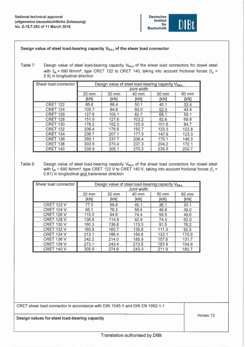
Design value of steel load-bearing capacity VRd ,s of the shear load connector
OIBt
Table 7: Design value of steel load-bearing capacity VRd,s of the shear load connectors for dowel steel
Table 8:
with fyk = 690 N/mm 2
, type CRET 122 to CRET 140, taking into account frictional forces (f�t =0.9) in longitudinal direction
Shear load connector Design value of steel load-bearing capacity VRd s Joint width
20mm 30mm 40mm 50 mm 60 mm [kN] [kN] [kN] [kN] kN]
CRET 122 85.6 66.4 50.1 40.1 33.4 CRET 124 105.7 84.8 65.0 52.0 43.4 CRET 126 127.8 105.1 82.7 66.1 55.1 CRET 128 151.9 127.6 103.2 82.6 68.8 CRET 130 178.2 152.0 125.9 101.6 84.7 CRET 132 206.4 178.6 150.7 123.3 102.8 CRET 134 236.7 207.1 177.5 147.9 123.3 CRET 136 269.1 237.7 206.4 175.1 146.3 CRET 138 303.5 270.4 237.3 204.2 172.1 CRET 140 339.9 305.1 270.3 235.5 200.7
Design value of steel load-bearing capacity VRd,s of the shear load connectors for dowel steel with f
yk = 690 N/mm 2, type CRET 122 V to CRET 140 V, taking into account frictional forces (f,, =
0.81) in longitudinal and transverse direction
Shear load connector Desiqn value of steel load-bearinq capacitv VRd s Joint width
20mm 30 mm 40mm 50 mm 60 mm [kN] [kN] [kN] [kN] kN]
CRET 122 V 77.0 59.8 45.1 36.1 30.1 CRET 124 V 95.1 76.3 58.5 46.8 39.0 CRET 126 V 115.0 94.6 74.4 59.5 49.6 CRET 128 V 136.8 114.8 92.9 74.4 62.0 CRET 130 V 160.3 136.8 113.3 91.5 76.2 CRET 132 V 185.8 160.7 135.6 111.0 92.5 CRET 134 V 213.1 186.4 159.8 133.1 110.9 CRET 136 V 242.2 214.0 185.8 157.6 131.7 CRET 138 V 273.1 243.4 213.6 183.8 154.9 CRET 140 V 305.9 274.6 243.3 211.9 180.7
CRET shear load connector in accordance with DIN 1045-1 and DIN EN 1992-1-1
Design values for steel load-bearing capacity Annex 13
Translation authorised by DIBt

National technical approval
(allgemeine bauaufsichtliche Zulassung)
No. Z-15.7-253 of 11 March 2016
Deutsches
Institut
für
Bautechnik OIEt
Design values for concrete load-bearing capacity VRd ,ct and VRd ,c of CRET shear load connectors 122 to 140 or 122 V to 140 V
The design values for the concrete load-bearing capacity specified below apply to: - A min im um spacing of the shear load connector axes of a � (3 dm + lc1 ) and a � 3 (c1 + f/2)- The reinforcement spacings, concrete covers and reinforcement rod diameters specified in Tables 1 to
6
Table 9:
Shear load connector
CRET 122
CRET 124
Design values VRd,ct (punching shear verification) and VRd ,c (verification within rear suspended reinforcement) of the concrete load-bearing capacity of the shear load connectors CRET 122 and CRET 124
Thickness VRdcl of C20/25 C30/37 C40/50
member
rmml fkNl fkNl fkNl
180 62.0 71.0 78.2 200 79.3 90.7 99.9 220 95.9 109.8 120.8 240 115.2 131.8 145.1 250 120.8 138.3 152.2
200 79.9 91.5 100.7 220 96,6 110.6 121.7 240 115.9 132.7 146.1 250 121.6 139.2 153.2 260 142.2 162.8 179.2 280 155.3 177.7 195.6
VRdc C20/25 C30/37
fkNl fkNl
45.0 55.8 61.9 76.8 79.2 98.0 95.1 118.1 98.7 122.8
62.0 77.0 79.4 98.2 95.4 118.6 99.1 123.3
121.2 150.3 129.5 161.1
Asx,1 C40/50
fkNl
65.1 4 012 89.4 4 014
114.1 4 016 137.8
6 014 143.5
89.7 4 014
114.4 4 016 138.5
6 014 144.2 175.2
6 016 188.2
Asx,2
4 012 4 014 4 016
4 014
4 014 4 016
4 014
4 016
Asy
2 012 2 014 2 016
3 014
2 014 2 016
3 014
4 016
CRET shear load connector in accordance with DIN 1045-1 and DIN EN 1992-1-1
Design values for concrete load-bearing capacity Annex 14
Translation authorised by DIBt

National technical approval
(allgemeine bauaufsichtliche Zulassung)
No. Z-15. 7-253 of 11 March 2016
Deutsches Institut
für Bautechnik OIBt
Table 10: Design values VRct,ct (punching shear verification) and VRct,c (verification within rear suspended reinforcement) of the concrete load-bearing capacity of the shear load connectors CRET 126 to CRET 136
Shear load Thickness VRdct VRdc connector of C20/25 C30/37 C40/50 C20/25 C30/37 C40/50
member fmml fkNl fkNl [kN] [kN] [kN] [kN]
CRET 126 220 90.0 103.1 113.4 72.7 90.7 106.1 240 115.9 132.7 146.1 98.5 122.6 143.3 250 127.5 146.0 160.7 102.1 127.3 149.0 260 143.1 163.8 180.3 121.5 150.8 175.9 280 156.2 178.8 196.8 129.9 161.7 188.9
CRET 128 240 120.3 137.7 151.6 98.8 123.1 144.0 250 135.8 161.2 177.4 120.8 149.9 174.8 260 146.6 168.9 185.8 125.0 155.4 181.5 280 165.2 189.1 208.1 133.4 166.3 194.5 300 173.9 199.1 219.1 144.0 180.3 211.5 320 187.4 214.5 236.1 145.3 182.0 213.6 340 220.4 252.2 277.6 182.9 228.5 267.7
CRET 130 260 147.8 169.9 187.0 127.1 158.2 184.9 280 161.5 184.9 203.5 137.0 171.3 200.8 300 186.9 214.0 235.5 172.3 214.8 251.2 320 201.6 230.8 254.1 174.9 218.3 255.5 340 221.4 253.4 278.9 185.9 232.5 272.7 350 229.0 262.2 288.6 191.4 239.6 281.2
CRET 132 280 170.5 203.5 223.9 170.3 212.3 248.4 300 192.7 220.6 242.8 181.6 227.0 266.1 320 213.3 244.1 268.7 184.3 230.5 270.4 340 234.2 268.0 295.0 195.3 244.8 287.5 350 242.3 277.3 305.2 200.7 251.8 296.0 360 256.0 293.1 322.6 206.1 258.8 304.4 380 265.2 303.6 334.1 216.7 272.7 321.1
CRET 134 300 196.0 226.8 249.6 184.5 230.9 270.9 320 214.3 245.4 270.1 187.3 234.5 275.3 340 235.3 269.3 296.4 198.3 248.9 292.5 350 243.4 278.6 306.6 203.8 255.9 301.0 360 257.2 294.4 324.0 209.2 263.0 309.5
CRET 136 320 215.4 246.6 271.4 190.3 238.5 280.2 340 236.3 270.5 297.8 201.4 252.9 297.5 350 244.5 279.8 308.0 206.9 260.0 306.1 360 258.3 295.7 325.4 212.3 267.1 314.6
CRET shear load connector in accordance with DIN 1045-1 and DIN EN 1992-1-1
Design values for concrete load-bearing capacity
Translation authorised by DIBt
Asx,1
6 012
6 014
6 016
6 014
6 016
8 014
8 016
6 016 8 014
8 016
8 016
8 016
8 016
Asx,2
2 012
4 014
4 016
6 014
6 016
8 016
6 014
8 016 6 016 6 014
6 016
8 016
6 016
8 016
10 016
8 016 6 016
8 016
6 016
8 016
Asy
3 012 3 014 4 014
4 016
3 014
4 016
5 014
5 016
4 016 5 014
5 016
6 016
7 016
8 016 6 016
6 016
7 016
8 016
7 016
8 016
Annex 15

National technical approval
(allgemeine bauaufsichtliche Zulassung)
No. Z-15. 7-253 of 11 March 2016
Deutsches
Institut
für
Bautechnik UIBt
Table 11: Design values VRd ,ct (punching shear verification) and VRd ,c (verification within rear suspended
Shear load connector
CRET 138
CRET 140
Table 12:
Shear load connector
CRET 122 V
CRET 124 V
reinforcement) of the concrete load-bearing capacity of the shear load connectors CRET 138 to CRET 140
Thickness VRdct of C20/25 C30/37 C40/50
member [mm] [kN] [kN] fkNl 340 236.3 270.5 297.8 350 244.5 279.8 308.0 360 258.3 295.7 325.4
274.6 332.7 366.2 380 280.6 321.2 353.5
304.4 362.4 398.9 400 291.3 333.5 367.0
335.4 383.9 422.6 450 340.2 389.4 428.6
392.0 448.8 494.0 404.1 508.9 560.2
350 245.6 281.1 309.4 260.3 321.9 354.3
360 259.4 297.0 326.9 274.6 332.7 366.2
380 281.7 322.5 354.9 304.4 362.4 398.9
400 299.0 342.3 376.7 335.6 392.6 432.1
450 356.0 407.5 448.5 408.8 468.0 515.1 406.0 532.1 586.2
VRdc C20/25 C30/37
fkNl fkNl 208.4 262.1 213.9 269.2 219.3 276.3 260.4 324.0 230.0 290.2 274.3 342.1 240.6 304.0 288.1 359.9 266.7 337.9 321.6 403.4 427.3 531.9
214.6 270.3 259.2 322.5 220.1 277.3 266.2 331.7 230.8 291.4 280.2 349.7 241.5 305.2 293.9 367.6 267.6 339.2 327.4 411.1 428.2 533.2
C40/50
fkNl 308.6 317.2 325.7 378.6 342.5 400.3 359.1 421.8 400.0 474.2 621.7 318.5 376.8 327.1 387.8 343.9 409.6 360.6 431.0 401.6 483.4 623.3
Asx,1
8 016
8 020 8 016 8 020 8 016 8 020 8 016 8 020 8 025 8 016 8 020 8 016 8 020 8 016 8 020 8 016 8 020 8 016 8 020 8 025
Asx,2
8 016
8 020 10 016 8 020
10 016 10 020 12 016 12 020 12 025 8 016 8 020 8 016 8 020
10 016 8 020 10 016 10 020 12 016 12 020 12 025
Asy
7 016
8 016 7 020 8 016 8 020 7 016 7 020 7 016 7 020 7 025
7 016 7 020 8 016 7 020 8 016 8 020 8 016 8 020 9 016 9 020 9 025
Design values VRd,ct (punching shear verification) and VRd,c (verification within rear suspended reinforcement) of the concrete load-bearing capacity of the shear load connectors CRET 122 V and CRET 124 V, taking into account frictional forces (f
p = 0.9)
Thickness VRdct VRdc Asx,1 Asx,2 Asy of C20/25 C30/37 C40/50 C20/25 C30/37 C40/50
member [mml fkNl fkNl [kNl [kNl [kNl fkNl 180 56.3 64.4 70.9 37.6 46.5 54.1 4 012 4 012 1 012 200 72.3 82.8 91.1 50.5 62.4 72.5 4 014 4 014 1 014 220 87.3 100.0 110.0 65.3 80.5 93.4 4 016 240 103.2 118.2 130.1 70.5 87.2 101.4 4 016
6 016 1 016
250 109.1 124.9 137.5 73.0 90.4 105.4 200 72.3 82.8 91.1 52.4 64.8 75.4 4 014 4 014 1 014 220 88.0 100.7 110.8 65.4 80.7 93.7
4 016 4 016
1 016 240 103.9 119.0 130.9 70.6 87.4 101.8 6 016 250 115.1 131.7 145.0 84.3 104.7 122.2
6 014 4 014 2 014 260 120.4 137.8 151.7 87.6 109.0 127.4 280 140.7 161.1 177.3 108.1 134.2 156.4 6 016 4 016 2 016
CRET shear load connector in accordance with DIN 1045-1 and DIN EN 1992-1-1
Design values for concrete load-bearing capacity Annex 16
Translation authorised by DIBt

National technical approval
(allgemeine bauaufsichtliche Zulassung)
No. Z-15.7-253 of 11 March 2016
Deutsches
Institut
für
Bautechnik OIEt
Table 13: Design values VRct.ct (punching shear verification) and VRct,c (verification within rear suspended reinforcement) of the concrete load-bearing capacity of the shear load connectors CRET 126 V to CRET 136 V, taking into account frictional forces (f 1, = 0.9)
Shear load Thickness VRdct VRd C Asx,1 Asx,2 Asv connector of C20/25 C30/37 C40/50 C20/25 C30/37 C40/50
member fmml fkNl fkNl fkNl lkNl lkNl lkNl
CRET 126 V 220 85.4 97.7 107.5 61.3 76.3 89.1 6 012 2 012 2 012 240 109.8 125.7 138.3 83.7 104.0 121.4 250 115.1 131.7 145.0 87.0 108.3 126.6 6 014 4 014 2 014 260 120.4 137.8 151.7 90.3 112.6 131.8 280 150.6 172.3 189.7 111.3 138.3 161.4 6 016 4 016 3 016
CRET 128 V 240 114.7 131.3 144.5 81.5 101.3 118.2 250 120.1 137.5 151.3 84.9 105.7 123.5 6 014 6 014 2 014 260 125.6 143.8 158.2 88.3 110.0 128.7 280 145.9 167.0 183.8 111.6 138.8 162.1 300 158.1 180.9 199.1 119.2 148.6 173.8
6 016 6 016 2 016 320 170.4 195.0 214.7 121.5 151.6 177.5 340 182.8 209.3 230.4 128.8 161.1 189.0
CRET 130 V 260 144.1 164.9 181.5 105.8 131.4 153.2 6 016 280 161.0 184.4 202.9 113.6 141.4 165.3
6 016 3 016 300 174.4 199.7 219.8 121.1 151.2 177.1 320 188.0 215.2 236.8 123.5 154.3 180.8 8 016 340 216.3 247.6 272.5 156.7 195.5 228.9
8 016 4 016 350 223.7 256.1 281.8 161.6 202.0 236.7
CRET 132 V 280 164.2 188.0 206.9 121.2 151.6 177.7 8 014 6 014 5 014 300 189.9 217.4 239.3 152.4 190.1 222.5
6 016 320 204.7 234.3 257.8 155.0 193.5 226.6 340 224.5 257.0 282.8 165.1 206.5 242.3
8 016 5 016
350 232.2 265.8 292.5 170.0 213.0 250.0 8 016 360 239.9 274.6 302.2 174.9 219.3 257.7 380 251.0 287.3 316.2 184.7 232.0 272.9 10 016 4 016
CRET 134 V 300 190.9 218.5 240.5 155.1 193.7 226.8 6 016
320 205.7 235.4 259.1 157.7 197.1 231.0 340 225.5 258.2 284.1 167.8 210.2 246.8 8 016 5 016 350 233.2 267.0 293.8 172.8 216.7 254.5 8 016 360 240.9 275.8 303.5 177.7 223.1 262.3
CRET 136 V 320 206.7 236.6 260.4 160.4 200.7 235.5 6 016 340 226.6 259.3 285.4 170.6 213.9 251.3
8 016 5 016 350 234.2 268.1 295.1 175.6 220.4 259.1 8 016 360 242.0 277.0 304.9 180.5 226.8 266.8
CRET shear load connector in accordance with DIN 1045-1 and DIN EN 1992-1-1
Design values for concrete load-bearing capacity Annex 17
Translation authorised by DIBt

National technical approval
(allgemeine bauaufsichtliche Zulassung}
No. Z-15.7-253 of 11 March 2016
Deutsches
Institut
für
Bautechnik DIEt
Table 14: Design values VRd,ct (punching shear verification) and VRd ,c (verification within rear suspended reinforcement) of the concrete load-bearing capacity of the shear load connectors CRET 138 V
and CRET 140 V, taking into account frictional forces (fµ = 0.9)
Shear load Thickness VRdct VRdc connector of C20/25 C30/37 C40/50 C20/25 C30/37 C40/50
member [mml [kNl [kNl [kNl [kNl [kNl [kNl
CRET 138 V 340 233.5 267.3 294.3 176.9 222.1 261.3 350 241.5 276.4 304.2 181.9 228.6 269.1 360 249.4 285.5 314.3 186.8 235.0 276.8 380 270.7 309.9 341.1 196.6 247.8 292.1
304.3 348.4 383.4 237.8 296.1 346.2 400 294.7 337.4 371.3 206.3 260.3 307.2
338.1 387.0 425.9 250.2 312.3 365.6 450 343.8 393.5 433.1 229.9 291.1 344.3
394.8 451.9 497.4 280.6 351.8 413.2 409.9 514.4 566.2 367.2 456.4 532.7
CRET 140 V 350 242.5 277.6 305.6 182.5 229.6 270.3 360 250.5 286.8 315.6 187.5 236.0 278.0 380 271.8 311.2 342.5 197.4 248.8 293.4
306.8 351.2 386.6 233.9 291.2 340.4 400 295.9 338.7 372.8 207.1 261.4 308.6
340.7 390.0 429.3 246.5 307.5 360.0 450 345.0 394.9 434.6 230.8 292.3 345.8
397.6 455.1 500.9 277.1 347.3 407.9 411.9 516.2 568.2 368.0 457.5 534.2
CRET shear load connector in accordance with DIN 1045-1 and DIN EN 1992-1-1
Design values for concrete load-bearing capacity
Translation authorised by DIBt
Asx,1
8 016
8 020 8 016 8 020 8 016 8 020 8 025
8 016
8 020 8 016 8 020 8 016 8 020 8 025
Asx,2
8 016
10 016 8 020
10 016 10 020 12 016 12 020 12 025
8 016
10 016 8 020
10 016 10 020 12 016 12 020 12 025
Asy
6 016
6 020 7 016 7 020 7 016 7 020 7 025
6 016
6 020 7 016 7 020 7 016 7 020 7 025
Annex 18

CONTACT HALFEN WORLDWIDEHALFEN is represented by subsidiaries in the following countries, please contact us:
NOTES REGARDING THIS CATALOGUETechnical and design changes reserved. The information in this publication is based on state-of-the-art technology at the time of publication. We reserve the right to make technical and design changes at any time. HALFEN GmbH shall not accept liability for the accuracy of the information in this publication or for any printing errors.
The HALFEN GmbH subsidiaries in Germany, France, the Netherlands, Austria, Poland, Switzerland and the Czech Republic are Quality Management certified according to ISO 9001:2015, Certificate no. 202384-2016-AQ-GER-DAkkS.
Furthermore HALFEN is represented with sales offi ces and distributors worldwide. Please contact us: www.halfen.com
www.dnvgl.com
Austria HALFEN Gesellschaft m.b.H.Leonard-Bernstein-Str. 101220 Wien
Phone: +43 - 1 - 259 6770 E-Mail: [email protected]: www.halfen.at
Belgium / Luxembourg HALFEN N.V.Borkelstraat 1312900 Schoten
Phone: +32 - 3 - 658 07 20E-Mail: [email protected]: www.halfen.be
Fax: +32 - 3 - 658 15 33
China HALFEN Construction Accessories Distribution Co.Ltd.Room 601 Tower D, Vantone CentreNo. A6 Chao Yang Men Wai StreetChaoyang District Beijing · P.R. China 100020
Phone: +86 - 10 5907 3200E-Mail: [email protected]: www.halfen.cn
Fax: +86 - 10 5907 3218
Czech Republic HALFEN s.r.o.Business Center ŠafránkovaŠafránkova 1238/1155 00 Praha 5
Phone: +420 - 311 - 690 060E-Mail: [email protected]: www.halfen.cz
Fax: +420 - 235 - 314 308
France HALFEN S.A.S.18, rue Goubet75019 Paris
Phone: +33 - 1 - 445231 00E-Mail: [email protected]: www.halfen.fr
Fax: +33 - 1 - 445231 52
Germany HALFEN Vertriebsgesellschaft mbHLiebigstr. 14 40764 Langenfeld
Phone: +49 - 2173 - 970 - 0E-Mail: [email protected]: www.halfen.de
Fax: +49 - 2173 - 970 225
Italy HALFEN S.r.l. Soc. UnipersonaleVia F.lli Bronzetti N° 2824124 Bergamo
Phone: +39 - 035 - 0760711E-Mail: [email protected]: www.halfen.it
Fax: +39 - 035 - 0760799
Netherlands HALFEN b.v.Oostermaat 37623 CS Borne
Phone: +31 - 74-267 14 49E-Mail: [email protected]: www.halfen.nl
Fax: +31 - 74-267 26 59
Norway HALFEN ASPostboks 20804095 Stavanger
Phone: +47 - 51 82 34 00E-Mail: [email protected]: www.halfen.no
Poland HALFEN Sp. z o.o.Ul. Obornicka 28760-691 Poznan
Phone: +48 - 61 - 622 14 14E-Mail: [email protected]: www.halfen.pl
Fax: +48 - 61 - 622 14 15
Spain HALFEN IBERICA, S.L.Polígono Industrial Santa Ana c/ Ignacio Zuloaga 2028522 Rivas-Vaciamadrid
Phone: +34 - 91 632 18 40E-Mail: [email protected]: www.halfen.es
Fax: +34 - 91 633 42 57
Sweden Halfen ABVädursgatan 5412 50 Göteborg
Phone: +46 - 31 - 98 58 00E-Mail: [email protected]: www.halfen.se
Fax: +46 - 31 - 98 58 01
Switzerland HALFEN Swiss AGHertistrasse 25 8304 Wallisellen
Phone: +41 - 44 - 849 78 78E-Mail: [email protected]: www.halfen.ch
Fax: +41 - 44 - 849 78 79
United Kingdom /Ireland
HALFEN Ltd.A1/A2 Portland CloseHoughton Regis LU5 5AW
Phone: +44 - 1582 - 47 03 00E-Mail: [email protected]: www.halfen.co.uk
Fax: +44 - 1582 - 47 03 04
United States of America HALFEN USA Inc. PO Box 18687 San Antonio TX 78218
Phone: +1 800.423.91 40E-Mail: [email protected]: www.halfenusa.com
Fax: +1 877.683.4910
For countries not listed HALFEN International
HALFEN International GmbHLiebigstr. 14 40764 Langenfeld / Germany
Phone: +49 - 2173 - 970 - 0 E-Mail: [email protected]: www.halfen.com
Fax: +49 - 2173 - 970 - 849

© 2
019
HA
LFEN
Gm
bH, G
erm
any
appl
ies
also
to
copy
ing
in e
xtra
cts.
R -
081
- E -
05/1
9 PD
F 0
5/19
For further information please contact: www.halfen.com