GUARDRAIL - Florida Department of Transportation · Wing Wall 45^ Bridge Bridge Traffic Railing...
11
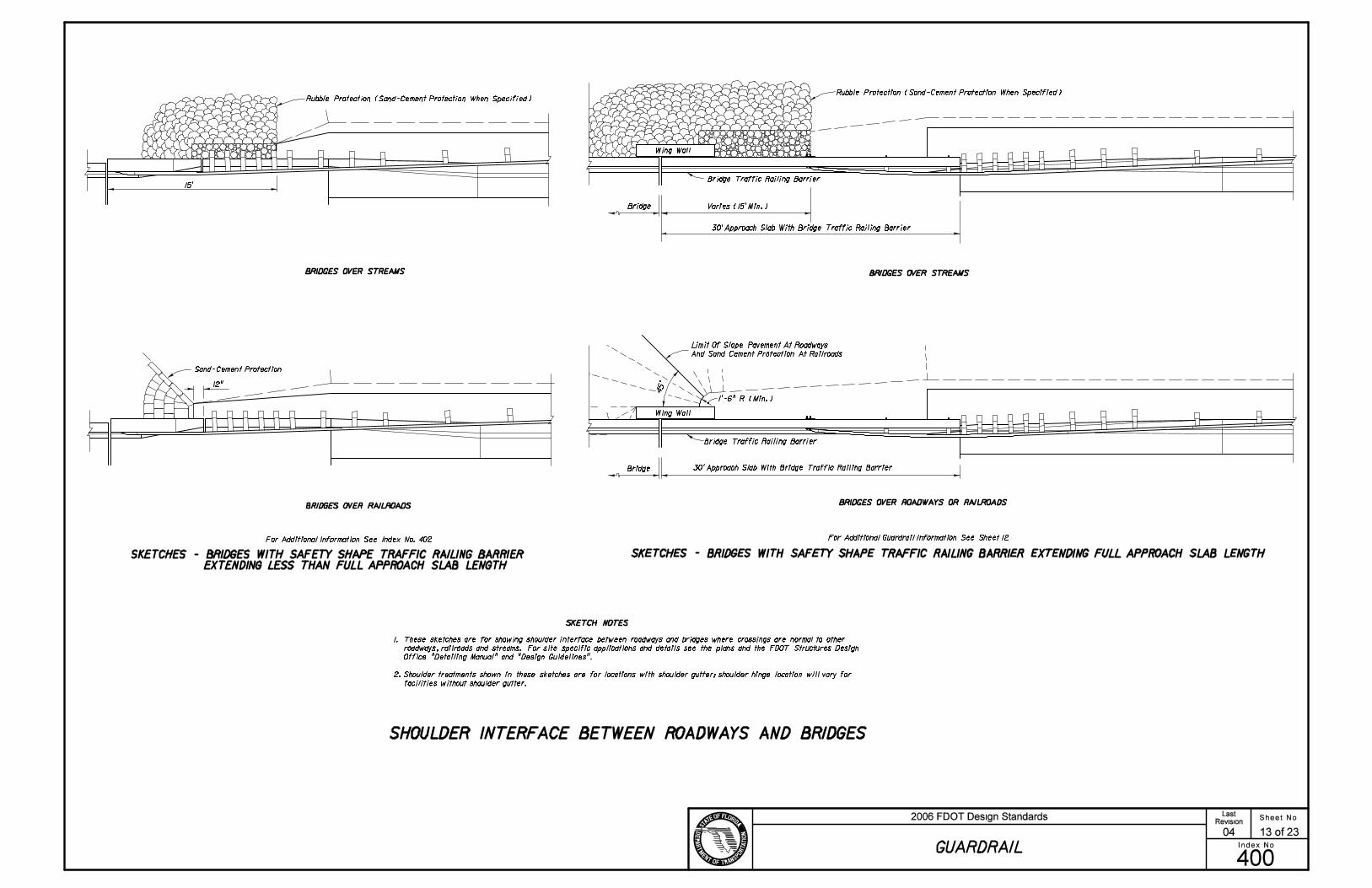
Sand-Cement Protection 15’ 12" Bridge Bridge Traffic Railing Barrier Wing Wall 45^ Bridge Bridge Traffic Railing Barrier Wing Wall SKETCHES - BRIDGES WITH SAFETY SHAPE TRAFFIC RAILING BARRIER EXTENDING LESS THAN FULL APPROACH SLAB LENGTH Varies (15’ Min.) SKETCHES - BRIDGES WITH SAFETY SHAPE TRAFFIC RAILING BARRIER EXTENDING FULL APPROACH SLAB LENGTH SKETCH NOTES For Additional Guardrail Information See Sheet 12 Limit Of Slope Pavement At Roadways And Sand Cement Protection At Railroads Rubble Protection (Sand-Cement Protection When Specified) Rubble Protection (Sand-Cement Protection When Specified) BRIDGES OVER STREAMS BRIDGES OVER RAILROADS BRIDGES OVER STREAMS BRIDGES OVER ROADWAYS OR RAILROADS 1’-6" R (Min.) 30’ Approach Slab With Bridge Traffic Railing Barrier 30’ Approach Slab With Bridge Traffic Railing Barrier SHOULDER INTERFACE BETWEEN ROADWAYS AND BRIDGES 1. These sketches are for showing shoulder interface between roadways and bridges where crossings are normal to other roadways, railroads and streams. For site specific applications and details see the plans and the FDOT Structures Design Office "Detailing Manual" and "Design Guidelines". 2. Shoulder treatments shown in these sketches are for locations with shoulder gutter; shoulder hinge location will vary for facilities without shoulder gutter. For Additional Information See Index No. 402 Sheet No. Index No. 2006 FDOT Design Standards Revision 400 04 GUARDRAIL 13 of 23 Last
Transcript of GUARDRAIL - Florida Department of Transportation · Wing Wall 45^ Bridge Bridge Traffic Railing...
Sand-Cement Protection
15’
12"
Bridge
Bridge Traffic Railing Barrier
Wing Wall
45^
Bridge
Bridge Traffic Railing Barrier
Wing Wall
SKETCHES - BRIDGES WITH SAFETY SHAPE TRAFFIC RAILING BARRIER
EXTENDING LESS THAN FULL APPROACH SLAB LENGTH
Varies (15’ Min.)
SKETCHES - BRIDGES WITH SAFETY SHAPE TRAFFIC RAILING BARRIER EXTENDING FULL APPROACH SLAB LENGTH
SKETCH NOTES
For Additional Guardrail Information See Sheet 12
Limit Of Slope Pavement At Roadways
And Sand Cement Protection At Railroads
Rubble Protection (Sand-Cement Protection When Specified)Rubble Protection (Sand-Cement Protection When Specified)
BRIDGES OVER STREAMS
BRIDGES OVER RAILROADS
BRIDGES OVER STREAMS
BRIDGES OVER ROADWAYS OR RAILROADS
1’-6" R (Min.)
30’ Approach Slab With Bridge Traffic Railing Barrier
30’ Approach Slab With Bridge Traffic Railing Barrier
SHOULDER INTERFACE BETWEEN ROADWAYS AND BRIDGES
1. These sketches are for showing shoulder interface between roadways and bridges where crossings are normal to other
roadways, railroads and streams. For site specific applications and details see the plans and the FDOT Structures Design
Office "Detailing Manual" and "Design Guidelines".
2. Shoulder treatments shown in these sketches are for locations with shoulder gutter; shoulder hinge location will vary for
facilities without shoulder gutter.
For Additional Information See Index No. 402
Sheet No.
Index No.
2006 FDOT Design StandardsRevision
400
04
GUARDRAIL
13 of 23
Last
���
���

CB
CB
A
A
PAVED SHOULDERS
PAVED SHOULDERS
Of Guardrail
Varies20’
Clear Zone
20’ Clear Zone
30’
Normal Face
Shoulder Pavt.
Varies
30’
Extended Shoulder
2’ Std.
Shoulder Pavt.
Normal Face
Of Guardrail
Of Guardrail
Of Guardrail
Extended Shoulder
Misc. Asphalt Pavt.V
ari
es
Vari
es
Vari
es
Normal Face
Of Guardrail
30’
Extended Shoulder
Varies
Varies
Varies
Normal Face
Of Guardrail
Shoulder Gutter
Shoulder Gutter
Shoulder Pavt.
Shoulder Gutter
Of Guardrail
Shoulder Pavt.Normal Face
Normal Face
SHOULDER GUTTER
Norm
al
Should
er
SHOULDER GUTTER DOUBLE FACE RAIL
(See Detail K)
Not Steeper Than 1: 10
Not Steeper Than 1: 10
Not Steeper Than 1: 10
GUARDRAIL LOCATION-DETAIL K
On 0.06 Rise
Normal Face
12
"
Connect Beginning Of Rubrail
To Back Side Of No. 3 Post
With Post Bolt
LOCATIONS ON FRONT SLOPES
Normal Face Of Guardrail Normal Face Of Guardrail
Normal Face
Of Guardrail
Traffic Lane
STANDARD LOCATIONS
*
Vari
es
See D
eta
il K
See D
eta
il K
Varie
s*
*
Varies
See Plan Below
1: 6 For 20’
14’ Clear Zone
SECTION AA (EXAMPLE FOR 20’ CLEAR ZONE)
SECTION AA (EXAMPLE FOR 30’ CLEAR ZONE) SECTION BB (EXAMPLE FOR 30’ CLEAR ZONE)SECTION CC (EXAMPLE FOR 30’ CLEAR ZONE)
1: 6 Reference Line
1: 3 (Max.) For
1: 3 (Max.) For
1: 3 (Max.)
1: 6 Reference Line1: 6 Reference Line
1: 3 (Max.) 1: 3 (Max.)
Normal Face Of Guardrail
Not Steeper Than 1: 10
Shoulder Line
10’
Misc. Asphalt Pavt. With
Paved Or Unpaved Shoulders
When Called For In The Plans
(See Detail K)
Transition Slope Transition SlopeTransition Slope
SHOULDERS, SLOPES AND MISCELLANEOUS PAVING FOR FLARED END ANCHORAGE ASSEMBLIES
Shoulder Line
10’
Shoulder Line
10’
1 : 15 To Normal Shoulder Break Point1 : 15 To Normal Shoulder Break Point
1 : 15 To Normal Shoulder Break Point
MISCELLANEOUS PAVING FOR STANDARD GUARDRAIL SECTIONS
Front Slope
(1 : 4 Or Flatter)
Flared End Anchorage
6" 6"
6"
4’
3’
4’-6" (Min.)
3’
6"
SHOULDER WITH OR WITHOUT 5’ PAVEMENT
8’
6’-6"
4’
3’
8’
6’-6"
4’
3’
8’
6’-6"
4’
8’
4’6"
7’
6"
3’
3’
Not Steeper Than 1 : 10
3’
SHOULDER WITH OR WITHOUT 5’ PAVEMENT
* 12’ For Shoulders 10’ And Wider;
8’ For Median Shoulders 8’ Or Less In Width; and,
Shoulder Width Plus 2’ For All Others Shoulders.
2’-0"
Rubrail (C6!8.2, Plates And Fastners or Bent Plate And
Fastners In Accordance With Standards RLR01 And RER01
Of AASHTO-AGC-ARTBA "A Guide To Standardized Highway
Barrier Hardware")
SLOPE
Acceptable to 25’
Acceptable to 26’
Acceptable to 27’
NOT RECOMMENDED
4:1
5:1
6:1
7:1
8:1
9:1
10:1
For shoulders less than 12’ in width
the tabulated values will be reduced
by the difference between 12’ and
the shoulder width.
Placement of guardrail on frontslopes
steeper than 4:1 not recommended.
WITH RUBRAIL
ACCEPTABLE
14’ to 27’
15’ to 25’
17’ to 22’
21’ to 24’
28’ to 45’
26’ to 45’
23’ to 45’
25’ to 45’
26’ to 45’
27’ to 45’
28’ to 45’
Cost of rubrail to be included in the
contract unit price for guardrail.
Notes:
Misc. Asphalt Pavt.Misc. Asphalt Pavt.
LATERAL PLACEMENT ON FRONT SLOPES (FROM EDGE OF TRAFFIC LANE)
Edge Of Traffic Lane
**8’ For 6’ Shoulders
10’ For 8’ Shoulders
12’ For 10’ And 12’ Shoulders
Applies To Left And Right Side Shoulders.
(See Index No. 525 For Shoulder Widths And Shoulder
Gutter Locations On Ramps And Auxiliary Lanes)
Edge Of Traffic LaneEdge Of Traffic Lane
2" Misc. Asphalt Pavt.
2" Misc. Asphalt Pavt.
2" Misc. Asphalt Pavt. 2" Misc. Asphalt Pavt.2" Misc. Asphalt Pavt.
2" Misc. Asphalt Pavt. 2" Misc. Asphalt Pavt.
2" Misc. Asphalt Pavt.
Sheet No.
Index No.
2006 FDOT Design StandardsRevision
400
07/01/05
GUARDRAIL
14 of 23
Last
���
���
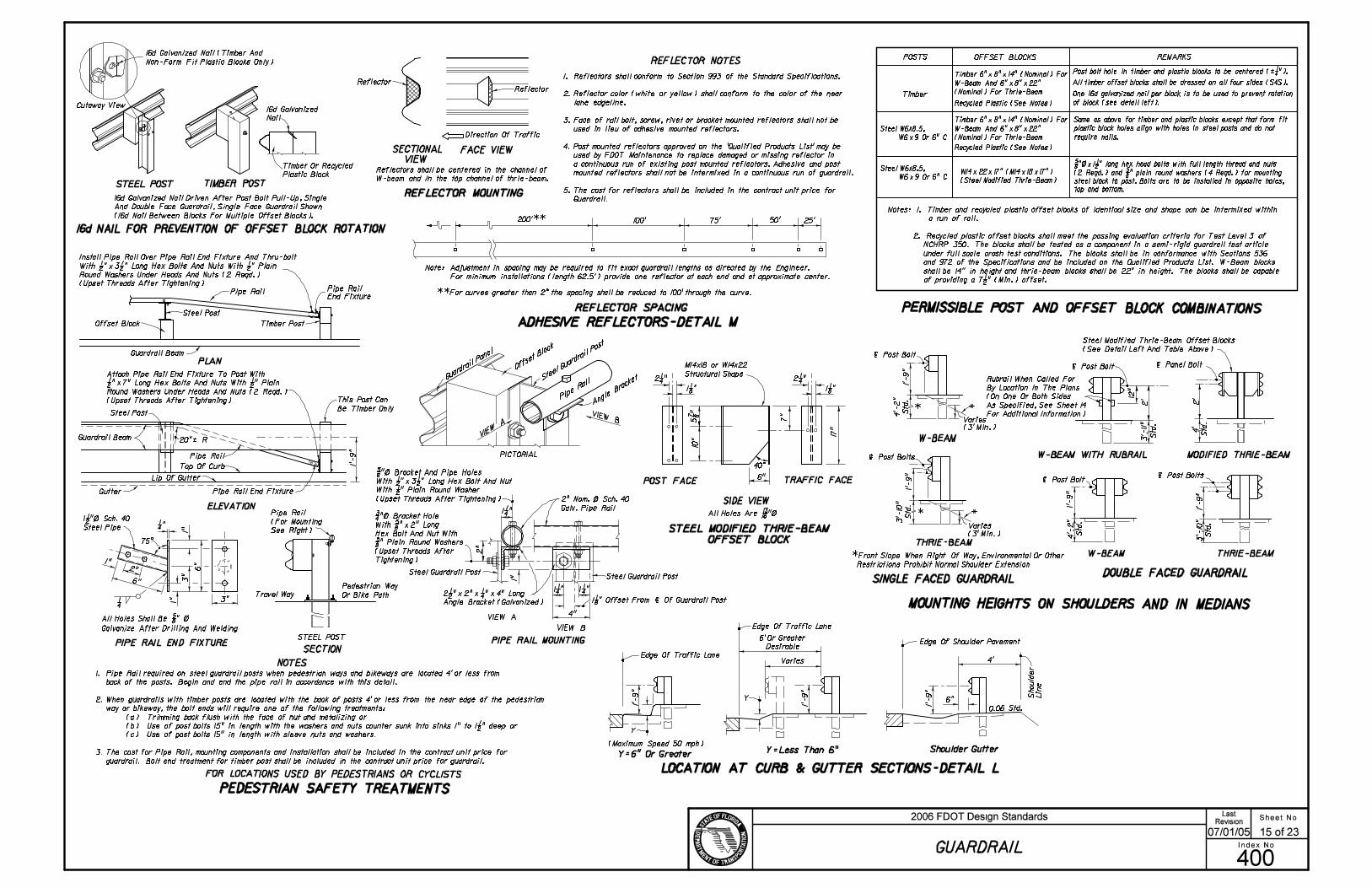
PERMISSIBLE POST AND OFFSET BLOCK COMBINATIONS
MOUNTING HEIGHTS ON SHOULDERS AND IN MEDIANS
SINGLE FACED GUARDRAIL
THRIE-BEAM
LOCATION AT CURB & GUTTER SECTIONS-DETAIL L
FACE VIEW
REFLECTOR MOUNTING
Desirable
Y
0.06 Std.
Should
er
Lin
e
Edge Of Shoulder Pavement
Shoulder Gutter
Y
THRIE-BEAM
| Post Bolt
Varies
Varies
Varies
Note: Adjustment in spacing may be required to fit exact guardrail lengths as directed by the Engineer.
REFLECTOR SPACING
ADHESIVE REFLECTORS-DETAIL M
25’200’** 100’ 75’ 50’
6’ Or Greater
Y=6" Or Greater
| Post Bolt
12
"
REFLECTOR NOTES
4’-2
"
Std
.
| Post Bolts
(3’ Min.)
ReflectorReflector
Direction Of Traffic
(3’ Min.)
5 7/
8 "
10"
40^
DOUBLE FACED GUARDRAIL
POST FACE
SIDE VIEW
TRAFFIC FACE
STEEL POST TIMBER POST
16d Galvanized
Nail
| Post Bolts| Post Bolt
| Panel Bolt
Gutter
Top Of Curb
1"
1"
1"
75^
1/4
20"‘ R
Steel Post
Steel Post
Guardrail Beam
PLAN
ELEVATION
Pipe Rail
End Fixture
PIPE RAIL END FIXTURE
3"
1/4 "
3"
2"
Guardrail Beam
Galvanize After Drilling And Welding
Travel Way
SECTION
Pedestrian Way
Or Bike Path
Pipe Rail
Pipe Rail
W-BEAM
W-BEAM
*
*
FOR LOCATIONS USED BY PEDESTRIANS OR CYCLISTS
Timber Post
Pipe Rail End Fixture
STEEL POST
1"Pipe Rail
(For Mounting
See Right)
PIPE RAIL MOUNTING
VIEW A
VIEW B
1. Reflectors shall conform to Section 993 of the Standard Specifications.
2. Reflector color (white or yellow) shall conform to the color of the near
lane edgeline.
3. Face of rail bolt, screw, rivet or bracket mounted reflectors shall not be
used in lieu of adhesive mounted reflectors.
4. Post mounted reflectors approved on the ’Qualified Products List’ may be
used by FDOT Maintenance to replace damaged or missing reflector in
a continuous run of existing post mounted reflectors. Adhesive and post
mounted reflectors shall not be intermixed in a continuous run of guardrail.
5. The cost for reflectors shall be included in the contract unit price for
Guardrail.
Steel Guardrail PostSteel Guardrail Post
This Post Can
Be Timber Only
Rubrail When Called For
By Location In The Plans
(On One Or Both Sides
As Specified, See Sheet 14
For Additional Information)
Lip Of Gutter
16d NAIL FOR PREVENTION OF OFFSET BLOCK ROTATION
SECTIONAL
VIEWTimber Or Recycled
Plastic Block
MODIFIED THRIE-BEAMW-BEAM WITH RUBRAIL
*Front Slope When Right Of Way, Environmental Or Other
Restrictions Prohibit Normal Shoulder Extension
PICTORIAL
Offset Block
STEEL MODIFIED THRIE-BEAM
OFFSET BLOCK
16d Galvanized Nail Driven After Post Bolt Pull-Up, Single
And Double Face Guardrail, Single Face Guardrail Shown
(16d Nail Between Blocks For Multiple Offset Blocks).
16d Galvanized Nail (Timber And
Non-Form Fit Plastic Blocks Only)
Cutaway View
Install Pipe Rail Over Pipe Rail End Fixture And Thru-bolt
With 1/2 "!3 1/2 " Long Hex Bolts And Nuts With 1/2 " Plain
Round Washers Under Heads And Nuts (2 Reqd.)
(Upset Threads After Tightening)
Attach Pipe Rail End Fixture To Post With
1/2 "!7" Long Hex Bolts And Nuts With 1/2 " Plain
Round Washers Under Heads And Nuts (2 Reqd.)
(Upset Threads After Tightening)
1’-
9"
1 1/2 "\ Sch. 40
Steel Pipe
6"
6"
All Holes Shall Be 5/8 " \
1’-
9"
1’-
9"
1’-
9"
6"
4’
4"
1 1/4 " 1 1/4 "2 1/2 "!2"! 1/4 "!4" Long
Angle Bracket (Galvanized)
2" Nom. \ Sch. 40
Galv. Pipe Rail
3/4 "\ Bracket Hole
With 5/8 "!2" Long
Hex Bolt And Nut With
5/8 " Plain Round Washers
(Upset Threads After
Tightening)
5/8 "\ Bracket And Pipe Holes
With 1/2 "!3 1/2 " Long Hex Bolt And Nut
With 1/2 " Plain Round Washer
(Upset Threads After Tightening)
1 1/4 "
1 1/8 "
2 1/4 "
6"
7"
All Holes Are 13/16 "\
1’-
9"
3’-
10
"
Std
.1
’-9
"
1’-
9"
4’-2
"
Std
.
2’ 2’
3’-
11
"
Std
.
4’
Std
.1
’-9
"3
’-1
0"
Std
.
**For curves greater than 2^ the spacing shall be reduced to 100’ through the curve.
Y=Less Than 6"(Maximum Speed 50 mph)
Reflectors shall be centered in the channel of
W-beam and in the top channel of thrie-beam.
2"
1 1/8 " Offset From | Of Guardrail Post
17
"
1 1/8 "
2 1/4 "
NOTES
1. Pipe Rail required on steel guardrail posts when pedestrian ways and bikeways are located 4’ or less from
back of the posts. Begin and end the pipe rail in accordance with this detail.
2. When guardrails with timber posts are located with the back of posts 4’ or less from the near edge of the pedestrian
way or bikeway, the bolt ends will require one of the following treatments:
(a) Trimming back flush with the face of nut and metalizing or
(b) Use of post bolts 15" in length with the washers and nuts counter sunk into sinks 1" to 1 1/2 " deep or
(c) Use of post bolts 15" in length with sleeve nuts and washers.
3. The cost for Pipe Rail, mounting components and installation shall be included in the contract unit price for
guardrail. Bolt end treatment for timber post shall be included in the contract unit price for guardrail.
PEDESTRIAN SAFETY TREATMENTS
For minimum installations (length 62.5’) provide one reflector at each end and at approximate center.
Timber
REMARKS
All timber offset blocks shall be dressed on all four sides (S4S).
One 16d galvanized nail per block is to be used to prevent rotation
of block (see detail left).
POSTS OFFSET BLOCKS
5/8 "\!1 1/2 " long hex head bolts with full length thread and nuts
(2 Reqd.) and 5/8 " plain round washers (4 Reqd.) for mounting
steel block to post. Bolts are to be installed in opposite holes,
top and bottom.
Post bolt hole in timber and plastic blocks to be centered (‘ 1/4 ").
Recycled Plastic (See Notes)
Timber 6"!8"!14" (Nominal) For
W-Beam And 6"!8"!22"
(Nominal) For Thrie-Beam
Timber 6"!8"!14" (Nominal) For
W-Beam And 6"!8"!22"
(Nominal) For Thrie-Beam
Recycled Plastic (See Notes)
Same as above for timber and plastic blocks except that form fit
plastic block holes align with holes in steel posts and do not
require nails.
W14!22!17" (M14!18!17")
(Steel Modified Thrie-Beam)
Steel Modified Thrie-Beam Offset Blocks
(See Detail Left And Table Above)
Notes: 1. Timber and recycled plastic offset blocks of identical size and shape can be intermixed within
a run of rail.
2. Recycled plastic offset blocks shall meet the passing evaluation criteria for Test Level 3 of
NCHRP 350. The blocks shall be tested as a component in a semi-rigid guardrail test article
under full scale crash test conditions. The blocks shall be in conformance with Sections 536
and 972 of the Specifications and be included on the Qualified Products List. W-Beam blocks
shall be 14" in height and thrie-beam blocks shall be 22" in height. The blocks shall be capable
of providing a 7 1/2 " (Min.) offset.
Steel W6x8.5,
W6!9 Or 6" C
Steel W6x8.5,
W6!9 Or 6" C
Edge Of Traffic Lane
Edge Of Traffic Lane
M14x18 or W14x22
Structural Shape
Sheet No.
Index No.
2006 FDOT Design StandardsRevision
400
07/01/05
GUARDRAIL
15 of 23
Last
���
���

10’ 10’
Sidewalk Without Utility Strip
See Detail L
A
A
B
C
B
C
SECTION AA
SECTION BB
SECTION CC
Curb And Gutter Type F
PLAN
DETAIL Q
Transition
Sidewalk (Varies)
Sidewalk (Varies)
Sidewalk (Varies)
0.02 (Std.)
0.02 (Std.)
0.02 (Std.)
13’
20’
R
45’
Sidewalk (Width Varies - 5’ Std.; 4’ Min.)
APPROACH TREATMENT FOR CURB AND GUTTER
This Standard Post Must
Be Timber When Steel Post
Used In Guardrail AheadCurb Transition
*
Flared End Anchorage Assembly
(MELT Shown)
Curb flare shall follow guardrail flare, see elsewhere
in this Index for additional guardrail flare information.
3’ 6’-8" 3’ 3’
6’
35’-4" Drop Curb
37’-6" Guardrail Flare
6’-6
"
1’-
9"
1’-
9"
4’
1’-
9"
21’-6" (Curb And Gutter Flare)
*Safety pipe rail is required when the back of steel
guardrail posts are 4’ or less from the near edge of
a pedestrian way or bikeway and post bolt treatment
is required when the back of timber posts are 4’ or
less from the near edge of a pedestrian way or
bikeway; see ’PEDESTRIAN SAFETY TREATMENTS’.
0’-9" (MELT)
1’-3 1/2 " (SRT-350 & REGENT)
2’-3 1/2 "(FLEAT-350)
2’-3 1/2 " SRT/HBA-6 POST
1’-1" (MELT)
1’-8 1/2 " (SRT-350 & REGENT)
1’-7" (FLEAT-350)
1’-7" SRT/HBA-6 POST
2" Misc. Asphalt
2" Misc. Asphalt
2" Misc. Asphalt
2" Misc. Asphalt
Sheet No.
Index No.
2006 FDOT Design StandardsRevision
400
07/01/05
GUARDRAIL
16 of 23
Last
���
���
Note: For Proprietary End Treatments See the Qualified Products List.

SPECIAL END SHOE ROUNDED END SECTION
BUFFER END SECTION
W-BEAM
3" Neutral Axis
2" 3"
Direction Of Traffic
Lap
LAPPLICATION
Rail Splice Bolt
Post Bolt -
Metalizing Permitted
Sheet Thickness
10"
Approach Beam,
End Section Or
End Shoe
L
Contour To Fit
Over Beam
Contour To Fit
Over Beam
3" Min.
FLARED END SECTION
^ ‘ For End251
2
30^
30^
3"
55^
55^
55^
(RECTANGULAR PLATE WASHER)
BEAM WASHER
HEX BOLTS AND NUTS
12 1
/4 "
15/16 " R
12"
4 1/4 "
12 1
/4 "
4 1/4 "
8 1/2 " 7 1/2 "2"
5/8 "
5/16 "
15/16
"
25"*
18"
10"
|
| Of Beam
Tolerance (-0,+ 1/16 ")
3/8 " R
25^
10^ (‘1^)
Recess (Both Sides)
(Min.) (In.)
12 1
/4 "
With End Anchorage
Varies
Varies
Field Bend With
Type MELT
Trailing Beam,
Terminal Section
Or End Shoe
|
5/8 " OVAL SHOULDER BUTTON HEAD BOLT
Post Bolt - Single Faced Guardrail Timber Posts
W-Beam Thrie-Beam W-Beam Thrie-Beam
6’-3"
SINGLE BEAM NESTED BEAMS
N/A N/A
N/A N/A
Note: The values shown should be utilized unless changes
are supported by imperical validation. Those desiring
to develop offset values from the simulated deflection
values shown in Table 5.4 of the AASHTO Roadside
Design Guide are cautioned to proceed only if back-
ground in the table development is understood.
THREAD
LENGTH
Measured From Face Of Guardrail To
Front Of Above Ground Rigid Hazard
Note: For beam washer requirements on end terminals, see individual
end anchorage assembly details. Washers are to be used where
necessary to accomplish alignment or where the posts bolt head
shows tendency to pull through the rail slot. Washers installed on
guardrail, between end anchorages, prior to July 1, 1990 may remain
in place until the guardrail is relocated or until repairs require
removal and reinstallment of a post bolt.
W-BEAM RAIL SPLICE
Note: For application information see individual
end anchorage assembly details.
W-BEAM BACK-UP PLATE
3 1/4 "
3 3/16 "
1 1/16 "
2 1/4 "
2 5/
16 "
3 1/
4 "
1 21/32 "
1 1/8
"
15/16 " R
29/32 "!1 1/8 " Slots
3/4 "!2 1/2 " Slot
3’-1 1/2 "
1’-6 3/4 "
4’
3’
3’-3"
2’-8" 2’-8"
2’-4"
2’-4"
2’
OFFSETS (Ft.)
POST
SPACING
(Ft.)
MINIMUM OFFSET FOR
SINGLE FACED GUARDRAIL (Ft.)
(In.)
1 1/4 " Full Length
4"
4"
4"
Special bolts having lengths of 10" or greater shall have a
thread length of not less than 4".
* Use of the 25" AASHTO-AGC-ARTBA standard length post bolt
on double faced guardrail that results in the bolt projecting more
than 3/4 " beyond the face of the nut after pull-up shall be trimmed
to 3/4 " reveal and metalized with organic zinc-rich coating. 5/8 " STEEL WASHER
11/16 "
1 3/4 "
Metal Thickness
9
64" Base
7/32 "
1 3/8 " R
1 3/3
2 "
1 3/8 "
3/4 "!2 1/2 " Slot
6"
11/16 "
1"\! 1/16 " Deep
1 1/4 "
5/8 " MODIFIED HEAVY
HEX NUT (RECESSED NUT)
1 1/2 "
1 3/4
"
11/16 "!1" Slot 7/8 "
3/16 " Base Metal
Thickness
4 1/4 "
Note: 5/8 "\ Steel washer required with splice bolts
29/32 "!1 1/8 " Slots
(Typ.) (8 Reqd.)
15/16 "\ Hole (Typ.)
(4 Reqd.)
3 1/
2 "
3 1/
2 "
3/4 "\ Hole For Use4"4" 4 1/4 "
3/4 "!2 1/2 " Slot
3/4 "!2 1/2 " Slot
2’-6"
3 3/
8 "
2’-3 1/2 "
3 3/
8 "
12 1
/4 "
2"4 1/4 " 4 1/4 "
29/32 "!1 1/8 " Slots
(Typ.) (8 Reqd.)
1’-
4 1
/8 "
Ap
pro
x.
29/32 "!1 1/8 " Slots
(Typ.) (4 Reqd.)
12 1
/4 "
6 1/4 " R
29/32 "!1 1/8 " Slots
(Typ.) (4 Reqd.)
12 1
/4 "
2" 8 1/2 " 7 1/2 "
1’-9
" o
r 2
’-6
"
1’-3" R Standard
(10 1/2 " R When Used
For End Anchorage
Type MELT)
1’-4
1/8
"
1’-4
1/8
"
3/4 "!2 1/2 " Slots
With Post Bolt And Nut
With 5/8 " Steel Washer
Under Nut
Note: The round washer is not intended for use under the recess nut for
the beam to beam rail splice. The washer is required under the recess
nut for connecting the beam to the special end shoe; under the post
bolt nut for connecting the beam to the timber post and offset blocks;
for connecting the beam to steel posts with timber offset blocks; under
the hex bolt head for securing the beam anchor plate to the beam; and,
for general guardrail connections by 5/8 "\ hex bolts and nuts. For
supplemental information see BEAM ANCHOR PLATE, PERMISSIBLE POST
RAIL SPLICE, THRIE-BEAM RAIL SPLICE, and THRIE-BEAM TERMINAL
CONNECTOR details.
AND OFFSET BLOCK COMBINATIONS, individual end anchorage assembly
details, SPECIAL STEEL GUARDRAIL POSTS, SPECIAL END SHOE, W-BEAM
Anchorage Type
MELT and CRT.
HS Hex bolts for THRIE-BEAM TERMINAL CONNECTORS shall conform to the
requirements of ASTM A449 (Type 1) with heavy hex nuts and washers. All other
hex bolts shall conform to the requirements of ASTM A563. Bolts, nuts and washers
shall be hot dip galvanized. Heavy hex nut may be used in lieu of hex nuts and hex
nuts used for jam nuts.
For applications where special bolts having lengths greater
than 25" are required, the Contractor may use a 5/8 "\ threaded
rod (field cut to length). A hex nut and beam washer shall
be used at the guardrail face with no more than 3/4 " of the
threaded rod projecting beyond the top of the nut. The
projecting thread on both ends shall be distorted to secure
the nuts, and both ends of the threaded rod metalized with
organic zinc-rich coating.
Post Bolt - Double Faced Guardrail Timber Posts
Double Faced Guardrail Steel Posts
Single Or Double Faced Guardrail
Timber Or Recycled Plastic Offset
Block(s) On Steel Post
As An Option, A Single 25"*
Long Post Bolt May Be Used
Sheet No.
Index No.
2006 FDOT Design StandardsRevision
400
07/01/05
GUARDRAIL
17 of 23
Last
���
���

3" Neutral Axis
2" 3"
THRIE-BEAM
Neutral Axis
Symmetrical
55^
55^
55^
25^
About |
3/8 " R
15/16 " R
15/16 " R
29/32 "!1 1/8 " Slots
3/4
"!2
1/2
" S
lots
Tolerance (-0,+ 1/16 ")
10^ (‘1^)
Sheet
Thickness
THRIE-BEAM TERMINAL CONNECTOR
4 1/4 " 2"
20
"
12 1
/4 "
6’-3"
2" Min.
W-THRIE BEAM TRANSITION SECTION
16"
2"
BACK VIEWSECTIONS
Hex (Jam) Nut
Hex Nut
BEAM ANCHOR PLATE
W-Beam
Anchor Plate
15/16 " R
3/8 " R
1/4
Three
Sides
35^
Swage Fitting
CABLE ASSEMBLY
Swage Connected To Studs
5 1/4 "
3/8 "
24
"
12
"
L
BEARING PLATE
BREAKAWAY TERMINAL
POST SLEEVE
18"
L
24"
SOIL PLATES
(Typ.) (8 Reqd.)
Direction Of Traffic
Lap
4 1/4 "
THRIE-BEAM RAIL SPLICE
Trailing Beam, W-Thrie
Beam Transition Section
Or Terminal Connector
Approach Beam, W-Thrie
Beam Transition Section
Or Terminal Connector
4 1/4 "
3/4 "!2 1/2 " Post Bolt Slots (Typ.)
29/32 "!1 1/8 " Splice Bolt Slots (Typ.)
3’-1 1/2 "3’-1 1/2 "
2" Min.4 1/4 "4 1/4 "2"
3/4 "!2 1/2 " Post Bolt
Slots (2 Reqd.)
29/32 "!1 3/4 " Slots
Rotated 50^ (Typ.)
(12 Reqd.)
4 1/4 "4 1/4 "
3 3/
8 "
2’-6"
4" 4"
Note: 5/8 "\ steel washer required with splice bolts
15/16 "\ Holes (Typ.)
(7 Reqd.)
3/4 "\ Holes
(2 Reqd.)
20" (
‘ 1/4
")
3 13/1
6 "3 1
3/16 "
3 13/1
6 "3 1
3/16 "
3/4 "!2 1/2 " Slots (2 Per Beam)
With Post Bolts And Nuts
With 5/8 " Steel Washers
Under Nuts (2 Reqd.)
4 1/4 "
3 1/4 "
3 3/16 "
2 1/4 "
1 1/16 "
1 21/32 "
2 3/
8 "
3 1/
4 "
1 1/8
"3
1/4
"
20" (
‘ 1/4
")
1/4 " Steel P, Galvanized
9"
3/4 "\ Holes
6"9" 9"
9" 9"6"
24"
3/4 "\ Holes
5/8 " Steel P
5"
8"
1 1/8 "\ Hole
4"
8"
6"
3/4 "\ Holes
3/4 "\ Holes
1 15/1
6 "
1 5/8 "
1 3/4
"
2 3/8 "
3 3/8 "
3/4 "\ Holes
4"4"4"2"
1"\ Anchor Rod And
Cable Assembly
Shaped Steel Plate
(16"!12 9/16 "! 3/16 ")
1"\!7" Stud, Full Threads,
Galvanized (Both Ends)
6’-6"
7"
1 5/8
"
1 1/4
"
3/4 "\ Galvanized Cable (6!19)
3/8 "
2 11/16 "
5 1/2
64
9Washer (2" OD, 1 1/16 "ID, Thick)
3/8 "!2 3/4 "!3" Steel End Plate
With 1 1/8 " Center Hole
2" Nom. Dia.
(2.067" ID, 2.375" OD)
Note: Cable assemblies shall be in accordance with the specifications of
AASHTO-AGC-ARTBA ’A Guide To Standardized Highway Barrier Hardware’
Cable Anchor Assembly FCA01. An additional cable assembly 9’ in length with a
swaged fitting on one (1) end is required for each end anchorage assembly Type CRT.
5/8 "-11!1 1/2 " Long Hex Head
Bolts And Nuts With Plain
Round Washers Under Heads
(8 Reqd.)
2"4"
8"
8"
3 13/16 "
1 1/2 "
SPECIAL END SHOETHRIE-BEAM TERMINAL CONNECTOR FILLER PLATE
2 7/
8 "
7 5/
8 "
7 5/
8 "
12"
21"
3 13/1
6 "
3 13/1
6 "
2"4" 4"
5/8 " Plate For Bridge Traffic Railing Barrier
1/4 " Plate For Barrier Walls 1/4 " Plate For All Applications
12"
12"
2 3/
8 "
2 3/
8 "
2"4" 4"
3 1/
2 "
3 1/
2 "
3/4 "\
Hole
All Holes 1"\ Except As Shown
GALVANIZED STEEL BACK-UP PLATES FOR CONNECTING SPECIAL END SHOES AND TERMINAL
CONNECTORS TO CONCRETE BRIDGE TRAFFIC RAILING BARRIERS AND CONCRETE BARRIER WALLS
1 1/4 " Plate
See Detail J For Application
| Post Bolt Slot
Sheet No.
Index No.
2006 FDOT Design StandardsRevision
400
07/01/05
GUARDRAIL
18 of 23
Last
���
���
12"
3/4 "!2 1/2 " Slot
6"
20" (
‘ 1/4
")
Back-up plate required behind rail elements at
intermediate (non-splice) posts when steel
offset block used.
THRI-BEAM BACK-UP PLATE
18"
S4S And
Treated
3"
1"
17
"
Open End
Galvanized
11"
Base Plate
14"
Adjusting Nuts
1"
Min
.
2 Holes Front And Back
SIDE VIEW FRONT VIEW
SIDE VIEW
FRONT VIEW
SIDE VIEW FRONT VIEW
Vari
es
FRONT VIEW SIDE VIEWTOP VIEW
Flanges (Total 4 Holes)
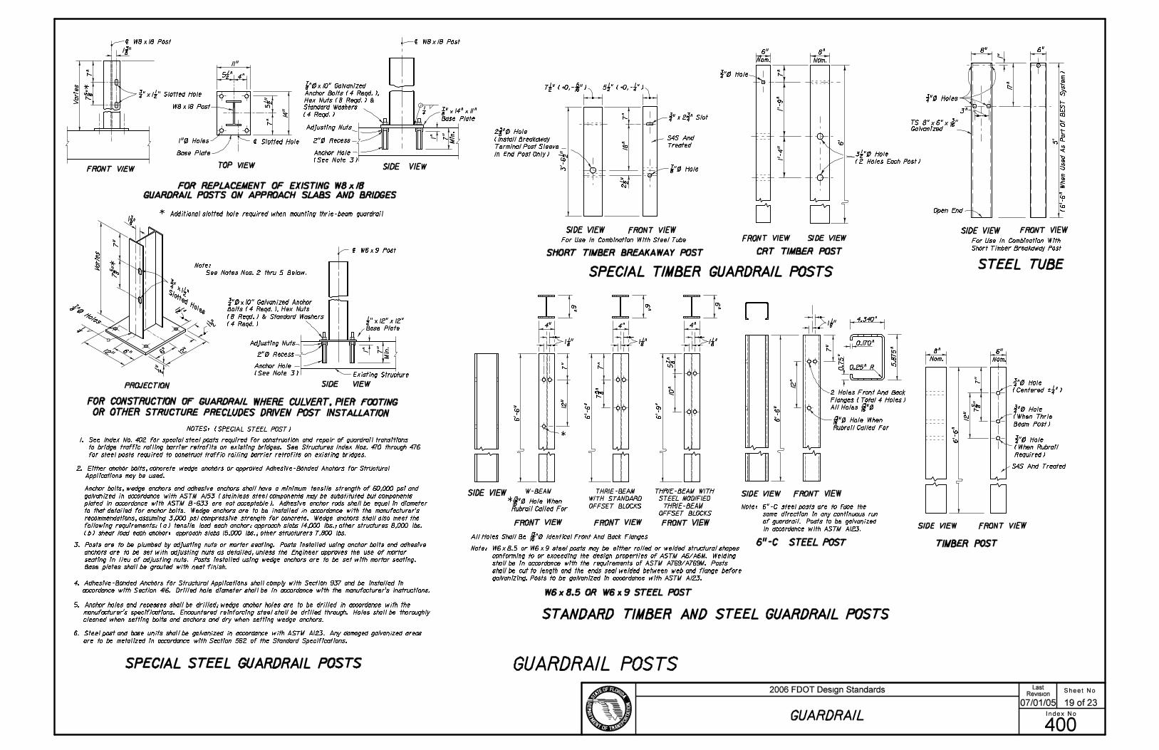
NOTES: (SPECIAL STEEL POST)
Existing Structure
Adjusting Nuts
SIDE VIEWPROJECTION
| Slotted Hole
Note:
See Notes Nos. 2 thru 5 Below.
Min
.
5 1/2 "
5 1/
2 "
1"
12
"
7 5/
8 "
12
"
plated in accordance with ASTM B-633 are not acceptable). Adhesive anchor rods shall be equal in diameter
3. Posts are to be plumbed by adjusting nuts or mortar seating. Posts installed using anchor bolts and adhesive
anchors are to be set with adjusting nuts as detailed, unless the Engineer approves the use of mortar
seating in lieu of adjusting nuts. Posts installed using wedge anchors are to be set with mortar seating.
Base plates shall be grouted with neat finish.
5. Anchor holes and recesses shall be drilled; wedge anchor holes are to be drilled in accordance with the
manufacturer’s specifications. Encountered reinforcing steel shall be drilled through. Holes shall be thoroughly
cleaned when setting bolts and anchors and dry when setting wedge anchors.
6. Steel post and base units shall be galvanized in accordance with ASTM A123. Any damaged galvanized areas
are to be metalized in accordance with Section 562 of the Standard Specifications.
SHORT TIMBER BREAKAWAY POST
Anchor Bolts (4 Reqd.),
Hex Nuts (8 Reqd.) &
7/8 "!14"!11"
Base Plate
CRT TIMBER POST
Nom. Nom.
FOR CONSTRUCTION OF GUARDRAIL WHERE CULVERT, PIER FOOTING
OR OTHER STRUCTURE PRECLUDES DRIVEN POST INSTALLATION
SPECIAL STEEL GUARDRAIL POSTS GUARDRAIL POSTS
SIDE VIEWFRONT VIEW
SIDE VIEW FRONT VIEWFRONT VIEWSIDE VIEW
TIMBER POST
STANDARD TIMBER AND STEEL GUARDRAIL POSTS
SPECIAL TIMBER GUARDRAIL POSTSSTEEL TUBE
For Use In Combination With
Short Timber Breakaway Post
For Use In Combination With Steel Tube
S4S And Treated
12
"
*
FRONT VIEW
W-BEAM
FRONT VIEW
7 5/
8 "
10"
5 7/
8 "
1/2 "!12"!12"
Base Plate
THRIE-BEAM WITH
STEEL MODIFIED
THRIE-BEAM
OFFSET BLOCKS
Nom. Nom.
7 1/2 " (+0,- 5/16 ") 5 1/2 " (+0,- 1/4 ")
THRIE-BEAM
WITH STANDARD
OFFSET BLOCKS
7 5/
8 "*
Note: 6"-C steel posts are to face the
same direction in any continuous run
of guardrail. Posts to be galvanized
in accordance with ASTM A123.
2. Either anchor bolts, concrete wedge anchors or approved Adhesive-Bonded Anchors for Structural
Applications may be used.
6"8"
7"
6’-6"
3/4 "\ Hole
(Centered ‘ 1/4 ")
3/4 "\ Hole
(When Thrie
Beam Post)
3/4 "\ Hole
(When Rubrail
Required)
4.340"
5.8
75
"
0.170"
0.25" R0.7
5"
7"
1 1/8 "
6’-6" All Holes 13/16 "\
13/16 "\ Hole When
Rubrail Called For
6"-C STEEL POSTAll Holes Shall Be 13/16 "\ Identical Front And Back Flanges
* 13/16 "\ Hole When
Rubrail Called For
6"
4"
1 1/8 "
6"6"
4"4"
1 1/8 "1 1/8 "
6’-9"
6’-6"
7"
7"
6’-6"
6"8"
3/4 "\ Holes
TS 8"!6"! 3/16 "
5’
(6
’-6
" W
hen
Used
As P
art
Of B
ES
T S
yste
m)
3 1/2 "\ Hole
(2 Holes Each Post)
6" 8"
7"
1’-
9"
1’-
4"
6’
3/4 "\ Hole
7"
2 1/
2 "
3’-
6 1
/2 "
3/4 "!2 3/4 " Slot
7/8 "\ Hole
2 3/8 "\ Hole
(Install Breakaway
Terminal Post Sleeve
In End Post Only)
| W8!18 Post
7"
7/8 "\!10" Galvanized
Standard Washers
(4 Reqd.)
2"\ Recess
4"
7"
1"\ Holes
W8!18 Post
| W8!18 Post
1 3/8 "
7"
3/4 "!1 1/2 " Slotted Hole
| W6!9 Post
3/4 "\!10" Galvanized Anchor
Bolts (4 Reqd.), Hex Nuts
(8 Reqd.) & Standard Washers
(4 Reqd.)
2"\ Recess
7"
Anchor bolts, wedge anchors and adhesive anchors shall have a minimum tensile strength of 60,000 psi and
recommendations, assuming 3,000 psi compressive strength for concrete. Wedge anchors shall also meet the
following requirements: (a) tensile load each anchor: approach slabs 14,000 lbs.; other structures 8,000 lbs.
(b) shear load each anchor: approach slabs 15,000 lbs.; other structurers 7,800 lbs.
Anchor Hole
(See Note 3)
Anchor Hole
(See Note 3)
W6!8.5 OR W6!9 STEEL POST
Note: W6!8.5 or W6!9 steel posts may be either rolled or welded structural shapes
conforming to or exceeding the design properties of ASTM A6/A6M. Welding
shall be in accordance with the requirements of ASTM A769/A769M. Posts
shall be cut to length and the ends seal welded between web and flange before
galvanizing. Posts to be galvanized in accordance with ASTM A123.
galvanized in accordance with ASTM A153 (stainless steel components may be substituted but components
to that detailed for anchor bolts. Wedge anchors are to be installed in accordance with the manufacturer’s
4. Adhesive-Bonded Anchors for Structural Applications shall comply with Section 937 and be installed in
accordance with Section 416. Drilled hole diameter shall be in accordance with the manufacturer’s instructions.
* Additional slotted hole required when mounting thrie-beam guardrail
FOR REPLACEMENT OF EXISTING W8!18
GUARDRAIL POSTS ON APPROACH SLABS AND BRIDGES
1. See Index No. 402 for special steel posts required for construction and repair of guardrail transitions
to bridge traffic railing barrier retrofits on existing bridges. See Structures Index Nos. 470 through 476
for steel posts required to construct traffic railing barrier retrofits on existing bridges.
Sheet No.
Index No.
2006 FDOT Design StandardsRevision
400
07/01/05
GUARDRAIL
19 of 23
Last
���
���
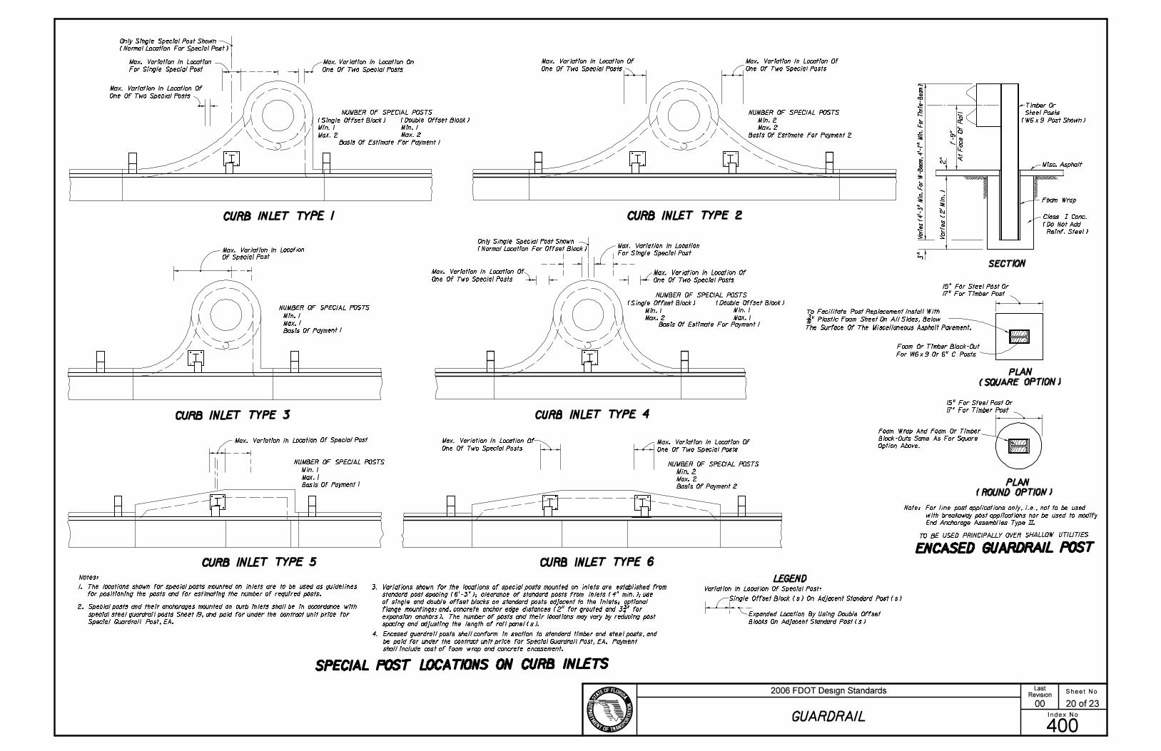
CURB INLET TYPE 1 CURB INLET TYPE 2
CURB INLET TYPE 3 CURB INLET TYPE 4
CURB INLET TYPE 5 CURB INLET TYPE 6
SECTION
PLAN
PLAN
ENCASED GUARDRAIL POST
SPECIAL POST LOCATIONS ON CURB INLETS
Min. 1
Max. 1
Basis Of Payment 1
Min. 1
Max. 1
Basis Of Payment 1
One Of Two Special Posts
Max. Variation In Location On
One Of Two Special Posts
Min. 1
Max. 2
Min. 1
Max. 2
Basis Of Estimate For Payment 1
Variation In Location Of Special Post:
Expanded Location By Using Double Offset
Min. 2
Max. 2
Basis Of Estimate For Payment 2
Min. 1
Max. 2
Min. 1
Max. 1
Basis Of Estimate For Payment 1
One Of Two Special Posts
Min. 2
Max. 2
Basis Of Payment 2
Misc. Asphalt
2" A
t F
ace O
f R
ail
To Facilitate Post Replacement Install With
Option Above.
Only Single Special Post Shown
1. The locations shown for special posts mounted on inlets are to be used as guidelines
for positioning the posts and for estimating the number of required posts.
2. Special posts and their anchorages mounted on curb inlets shall be in accordance with
3. Variations shown for the locations of special posts mounted on inlets are established from
LEGEND
One Of Two Special Posts One Of Two Special Posts
Only Single Special Post Shown
For Single Special Post
One Of Two Special Posts
One Of Two Special Posts
Timber Or
Steel Posts
Notes:
15" For Steel Post Or
17" For Timber Post
NUMBER OF SPECIAL POSTS
NUMBER OF SPECIAL POSTS
NUMBER OF SPECIAL POSTS
NUMBER OF SPECIAL POSTS
NUMBER OF SPECIAL POSTS
NUMBER OF SPECIAL POSTS
Max. Variation In Location
Of Special Post
Max. Variation In Location Of Special Post Max. Variation In Location Of
Max. Variation In Location Of
Max. Variation In Location
Max. Variation In Location OfMax. Variation In Location Of
Max. Variation In Location Of
Max. Variation In Location Of
Max. Variation In Location Of
One Of Two Special Posts
Max. Variation In Location
For Single Special Post
Foam Wrap
(Normal Location For Special Post)
Reinf. Steel)
(Single Offset Block) (Double Offset Block)
(Do Not Add
(Single Offset Block) (Double Offset Block)
(Normal Location For Offset Block)
(SQUARE OPTION)
(ROUND OPTION)
Single Offset Block (s) On Adjacent Standard Post (s)
Blocks On Adjacent Standard Post (s)
Block-Outs Same As For Square
Class ~ Conc.
4. Encased guardrail posts shall conform in section to standard timber and steel posts, and
shall include cost of foam wrap and concrete encasement.
TO BE USED PRINCIPALLY OVER SHALLOW UTILITIES
3"
15" For Steel Post Or
17" For Timber Post
spacing and adjusting the length of rail panel (s).
expansion anchors). The number of posts and their locations may vary by reducing post
Foam Or Timber Block-Out
Foam Wrap And Foam Or Timber
special steel guardrail posts Sheet 19, and paid for under the contract unit price for
Special Guardrail Post, EA.
be paid for under the contract unit price for Special Guardrail Post, EA. Payment
standard post spacing (6’-3"); clearance of standard posts from inlets (4" min.); use
of single and double offset blocks on standard posts adjacent to the inlets; optional
flange mountings; and, concrete anchor edge distances (2" for grouted and 3 3/4 " for
For W6!9 Or 6" C Posts
3/16 " Plastic Foam Sheet On All Sides, Below
Varie
s (
2’ M
in.)
Vari
es (
4’-
3" M
in.
Fo
r W
-Beam
, 4
’-7
" M
in.
Fo
r T
hri
e-B
eam
)
1’-
9"
(W6!9 Post Shown)
The Surface Of The Miscellaneous Asphalt Pavement.
Note: For line post applications only, i.e., not to be used
with breakaway post applications nor be used to modify
End Anchorage Assemblies Type ~~.
Sheet No.
Index No.
2006 FDOT Design StandardsRevision
400
00
GUARDRAIL
20 of 23
Last
���
���

End Measurement For Guardrail Payment
12" 16"
Cable To Be Drawn Taut
With Hand Wrench Prior
To Setting Jam Nuts
Steel Tube
Bearing Plate
compacting to provide full
passive soil resistance to
all surfaces of the tube and
soil plate.
plate as a unit with a dummy
timber post to prevent damage
to breakaway post.
Two 8d Nails ToPrevent Rotation
Anchor Plate Cable Assembly
FRONT VIEW
Note: Steel tubes and attached soil
plate may be installed by:
(1) Excavating, backfilling and
(2) Driving steel tube and soil
6’-3"
Post Sleeve
Soil Plate
12" 16"
Standard PostAnchor Plate
No Cover Required
Trailing Rail
Anchor Rod
30"
Concrete Anchor Block
30"
Steel End Plate, Washer, Hex
See Note Below
On Trailing End Section
Flared Or Rounded End Section
For Approach End Anchorage
Buffer End Section
Suit Anchorage Alignment.
Only One Anchorage Required.
Anchorage To Be On Approach
Rail When Both Approach
And Trailing Guardrails Are
See Note Below
Anchor Rod
30"
FRONT VIEW
TOP VIEW
Position Varies
End Measurement For Guardrail Payment
Approach Rail (Position Varies)
Nut And Hex (Jam) Nut
(Block To Be Positioned To
Connected.)6’-3"
1 1/2 " ID Pipe Sleeve
Beveled Washer And Hex Nut
3’-6
" S
td.
6’-3" To Next Post
Anchor PlateCable Assembly
Soil Plate
TOP VIEW - DOUBLE FACE
TOP VIEW - SINGLE FACE
Short Timber
Breakaway Post
CONCRETE ANCHOR BLOCK OPTION
Buffer End Section
END ANCHORAGE ASSEMBLY TYPE ~~
CABLE ANCHOR OPTION
Anchor Plate
Soil Plate
18"!24"! 1/4 "
TYPE ~~ NOTES
Flared End Section
(Rounded End Section When Guardrail
Located Adjacent To Pedestrian Way
Or Bikeway)
Turnbuckle to be used only for guardrail that is reset vertically. The existing anchor rod (1" or 1 1/4 " Dia.) shall be field cut,
End Section
Short Timber Breakaway Post
Short Timber Breakaway Post
Misc. Asphalt Pavt.
10’ Approach End Guardrail
Misc. Asphalt Pavt.
6’ Trailing End Guardrail
Misc. Asphalt Pavt. 10’ Approach End Guardrail
threaded 4" on each end, and, metalized in accordance with Sections 562 and 971 of the Standard Specifications. The cost
for cutting, threading, metalizing and the turnbuckle shall be included in the contract unit price for Reset Guardrail, LF.
1’-
9"
1"\ Galv.
Turnbuckle (6")
Galvanized 4"!4"! 3/4 " Plate
4’-9"
Turnbuckle (6")
5/8 "!25" Long Post Bolt And Nut With
Beam Washer Under Head And Under Nut
(Timber Post And Block)
5/8 "!18" Long Post Bolt And Nut With Beam Washer
Under Head And 5/8 " Plain Round Washer Under Nut
(Timber Post And Block)
5/8 "!10" Long Post Bolt And Nut
With Beam Washer Under Head And
5/8 " Plain Round Washer Under Nut
Misc. Asphalt Pavt.
6’ Trailing End Guardrail
1’-
9"
5/8 "!18" Long Bolt And
Nuts With 5/8 " Plain Round
Washer Under Head And Nut
(2 Req’d.)
5/8 "!10" Long Bolt And Nut With 5/8 " Plain
Round Washer Under Head And Nut
Timber Or Steel Post With Timber
Block May Be Used, Timber Post And
Block Shown (This Post Must Be
Timber In Steel Post Run Of Rail
Adjacent To Pedestrian Way
Or Bikeway, To Provide Anchorage
For Pipe Rails As Required)Misc. Asphalt Pavt.
Misc. Asphalt Pavt.
Misc. Asphalt Pavt.
1. Unless specified in the plans, the contractor can supply either the cable anchor option or the
concrete anchor block option.
2. Type ~~ end anchorage assemblies are approved for all speeds and are intended for use as:
(a) trailing end anchorages for single face free standing guardrail systems;
(b) approach end anchorages for single face free standing guardrail systems when end anchorage
is located outside of the clear zone; and,
(c) both approach and trailing ends of double face guardrail systems.
Crash cushions shall be constructed at or in lieu of approach Type ~~ end anchorages located
inside the clear zone.
3. These end anchors are to be paid for under the contract unit price for Guardrail, End Anchorage
Assembly (Type ~~), EA as called for in the plans or by permit.
Hex Nut & Hex (Jam) Nut
And Washer Each End
Hex Nut & Hex (Jam) Nut
And Washer Each End
The payment for the items of End Anchorage Assembly Type ~~ shall be full compensation for furnishing and installing the
Beam Anchor Plate, Anchor Rod, Pipe Sleeve, Anchor Block, either Flared, Rounded or Buffer End Section, and the necessary
hardware.
The payment for the items of End Anchorage Assembly Type ~~ shall be full
compensation for furnishing and installing either the Round or the Buffer
End Section, the Beam Anchor Plate, Cable Assembly, Pipe Sleeve, SoilPlate,
Steel Tube, Bearing Plate, Short Timber Breakaway Post, Offset Blocks and
the necessary hardware.
Sheet No.
Index No.
2006 FDOT Design StandardsRevision
400
07/01/05
GUARDRAIL
21 of 23
Last
���
���

SHELF ANGLE
BUFFERED END SECTION
STEEL STRUT AND YOKE ASSEMBLY
END ANCHORAGE ASSEMBLY TYPE MELT
Note: Assembly installed with channel turned down for right side
guardrail and turned up for left side guardrail.
PLAN
MODIFIED ECCENTRIC LOADER TERMINAL (MELT)
FRONT VIEW
TOP VIEW
1:
10 M
ax.
2 Spaces @ 6’-3"3 Spaces @ 4’-2"2 Spaces @ 6’-3"
No Bolts Through Rail To Posts
Beginning Of Length Of Need
Departure Line
1"
10’
CRT Timber Posts And Offset Blocks
Misc. Asphalt Pavt.
Standard
Timber Post
And Offset Block
MODIFIED ECCENTRIC LOADER TERMINAL NOTES
Misc. Asphalt Pavt.To Suit ShoulderTreatment, SeeSheet No. 14
Standard Guardrail,
Special Transition Or
Other Special Treatment
(Bolt Back Up Plate To No. 4 Post To Provide Nested Support For Rail)
Note: Bolt holes are not required, but, diaphragms with either manufacturer
produced two or three hole in line patterns are acceptable.
DIAPHRAGM PLATE (2 Reqd.)
1:
10
Max.
Shoulder Line
1 : 15 To Normal Shoulder Break Point
12
3
4
5
67
6’-3"
STRUT
Yoke Yoke
2"
C 6!8.2
4"
2"
1"
3"
2" @ 35^
4"
6" \ Hole
1’-
4"
2"
1’-0" 1’-4"
1’-
9"
1" R (Typ.)
End Measurement For Guardrail Payment
Steel Tube
Cable To Be Drawn Taut
With Hand Wrench PriorTo Setting Jam Nuts
Steel Tube
Bearing Plate
to provide full passive soil resistance
Two 8d Nails ToPrevent Rotation
Guardrail Pavement
Note: Steel tubes and attached soil
plate may be installed by:
Strut And Yoke Assembly
Diaphram Plate
Shelf Angle
Short Timber Breakaway Post
Breakaway Terminal
Post Sleeve
PLAN
13^
|
45^
PLAN
45^
45^
13^
13^
PLAN
ELEVATION FLAT PLATE LAYOUT
YOKE (2 Reqd.)
SECTION AA SECTION BB
10^
35^
Max.
See Note
Splice Bolts And Nuts
6"
3/4 "!1" Slot
2- 3/4 "!4"
Slots
32
291
1
8
Short Timber Breakaway
Post And Offset Block
Amber Retroreflective
Sheeting (See Above)
All Slots Shall Be !
(1) Excavating, backfilling and compacting
to all surfaces of the tube and soil plate.
(2) Driving steel tube and soil plate as a
unit with a dummy timber post to prevent
damage to breakaway post.
Buffer End Section
Soil Plate
Special End Shoe
Cable Assembly
Anchor Plate
Strut And Yoke AssemblyNut & Washer
Soil Plate
Steel Tube
Shelf Angle
Steel Tube
5/8 "!18" Long Post
Bolt & Nut With
5/8 " Plain Round
Washer Under Nut
Apply 8"!24" Amber
Retroreflective
Adhesive Sheeting
To Nose
5/8 "!1 3/4 " Long Button
Head Bolts And
Recess Nuts
(6 Reqd.)
5/8 "!10" Long Post Bolt And Nut With
Beam Washer Under Head And
5/8 " Plain Round Washer Under Nut 5/8 "!1 3/4 " Long Button Head Bolt
And Nut With Beam Washer
Under Head And Nut
5/8 "!10" Long Bolt And Nut With 5/8 " Plain
Round Wasner Under Head And Nut
2 3/8 "\ Hole
1’-8 3/4 "
2- 5/8 "!7 1/2 " Long Bolts And Nuts
With 5/8 " Plain Round Washer
Under Heads And Nuts
(2 Reqd. Per Steel Tube)
10 1
/2 "
R
12 1
/4 "
8 1/2 " 6 3/4 "
8 1/2 " 8 1/2 "25 3/4 " 25 3/4 "
8 1/4 " 8 1/4 "
4 7/
8 "
4 7/
8 "
1 7/16
"
5/8 "
1 1/8
"
5/16 " R
1 11/16 "
1 11/16 " @ 10^
3/4 " @ 35^6 3/4 "
3/8 " R (Typ.)
10 1/2 " R Before
Bending
6 1/
2 "
3/4 "
2 1/2 "
10 1/2 " R
6 1/4 "3 1/2 " 1 1/8 " 2 1/4 "
2 1/4 "
3/4 " 1 1/8
"
2 1/
4 "
1 1/8
"
1/4 " R
3/4 "!1 1/8 " Slot
8 1/
8 "
5/8 "
5’-7 1/4 "
7/8 "!2" Slot
5 1/2 "
5/16 " R
3/16 "
1/4 " Steel Plate 1 1/2 "
6 1/
8 "
7 1/
2 "
1. The MELT is applicable for design speeds up to 45 mph. The MELT is intended for use as an approach end guardrail
anchorage for shoulder guardrail. Its alignment is a flare from the normal guardrail alignment with an effective length of
37.5’ including three standard W-beam panel outside of any standard guardrail, guardrail transitions or other special
treatments.
2. This standard drawing is produced by the Florida Department Of Transportation solely for use by the Department and its
assignees. This standard drawing provides the general graphics and information necessary to field identify component parts
of the MELT and their incorporation into a whole system.
3. This standard drawing is sufficient for plan details for the MELT when installed in connection with shoulder guardrail and
precludes the requirement for shop drawing submittals unless the plans otherwise call for such submittals. The MELT shall
be assembled in accordance with the distributor’s detailed drawings, procedures and specifications.
4. The first two post must be short timber breakaway posts with steel foundation tubes and soil plates, post Nos. 3 thru 6 must
be CRT timber posts and post No. 7 must be a standard timber post.
5. The MELT can not be used in medians where horizontal clearance requires the use of a backrail.
6. See the General Notes for galvanizing requirements of metallic components.
7. If the plans call for the MELT at a specific location, substitutions with other end anchorage assemblies will not be permitted
unless approved by the Engineer. If the plans call for end anchorage assembly ’flared’ at a specific location, the contractor
has the option to construct any FDOT approved flared assembly that meet the applications for that location. Where a flared
end anchorage is called for in the plans, any approved substitution with a parallel end anchorage will not be eligible for VECP
consideration.
8. The MELT shall be paid for under the contract unit price for Guardrail, End Anchorage Assembly (Flared), EA and shall be full
compensation for furnishing and installing all components in accordance with the plans; the distributor’s detailed drawings,
procedures and specifications and this Index.
3’
4’-0"
2 1/2 " 4" 8"
1’-2"
2’-
1"
‘21’ R Fabricated
Over Beg. 6’-3"
37.5’ Flare (Lap Panels In Direction Of Near Traffic)
A
A
B
B
Soil Plate
24"!18"! 1/4 "
or
24"!24"! 1/4 "
Soil Plate
24"!18"! 1/4 "
or
24"!24"! 1/4 "
Hex Nut, Hex (Jam) Nut
And Washer Each End
Sheet No.
Index No.
2006 FDOT Design StandardsRevision
400
02
GUARDRAIL
22 of 23
Last
���
���
Diaphragm Plate

CONTROLLED RELEASE RETURN FOR SIDE ROAD AND DRIVEWAY ACCESS
CONTROLLED RELEASE RETURN NOTES
Note: To be constructed when flares and transitions or standard
radial returns can not be applied. See Sheet 11.
ReturnNo. Of CRT
Posts
Required Area Free
Of Hazards
L W
5
6
8
11
25’ x 15’
30’ x 15’
40’ x 20’
50’ x 20’
1’-
9"
1’-
4"
2’-4"
Slope=10:1
Or Flatter
3 1/2 " Dia. Holes
Centered In Post
8"
6’-3" 6’-3" 10’
Timber Breakaway Post
Anchor Plate
Bearing Plate
Buffer End Section
Special End Shoe
SPECIAL GUARDRAIL PIPE ATTACHMENTLOWER CABLE ATTACHMENT
TOP VIEW
TOP VIEW
TOP VIEW
FRONT VIEW
FRONT VIEWFRONT VIEW
6"
7"
Buffer End Section
Soil Plate
Soil Plate
Soil Plate
Misc. Asphalt Pavt.
Timber Breakaway Post
Cable (See Above)
Steel Tube
Steel Tube
Steel Plate (See Above)
Timber Breakaway Post
4"
Tack Weld 2 1/2 "!2 1/2 "! 1/4 "
Hole To Tubular SteelAttach W-beam To Steel Pipe With
No Connection To Post Is Required.
4 1/2 " Spacing Typ.
Special Guardrail Pipe
Attachment (See Left)
Special Guardrail Pipe
Attachment (See Left)
Timber Breakaway Post
1’-
9"
Steel Plate With 1 1/16 " Dia.
1:2 Max.
2’-0" Min.
GUARDRAIL END ANCHORAGE ASSEMBLY TYPE CRT
Options
L
Area Behind Guardrail To
Be Maintained Free Of Fixed
Object Hazards And Have
Slopes Not Steeper Than 1:2
W32’ R
CR
TP
osts
6’-
3" Spa
cing
Or
Dri
vew
ay
In
tersecti
ng
Ro
ad
way
Principle Highway
CR
T P
ost
CR
T P
osts
@ 6’-
3"
Posts
CR
T
8’ R
16’ R 24’ R
Connecting Guardrail On
Intersecting Roadway Or
Driveway
Guardrail End Anchorage Assembly
Type CRT (In Absence Of Connecting
Guardrail)
2" Misc. Asphalt Pavt.
8’
24’
16’
32’
Length Of Shop
Bent Panels
25’
12.5’
37.5’
50’
3/8 "!4"!12" Steel Plate
12"12" 16"
18"@
6’-
3"
6’-
3" Sp
acin
g
@
S
paci
ngSpa
cin
g
@
R
Nom.
Short Timber Breakaway Post
3/4 " Dia. x 9’-0" Cable With
One Swaged End (See Sheet 18)
To Next Post
Apply 8"!24" Amber
Retroreflective Sheeting
To Nose
Misc. Asphalt Pavt.
See Sheet 14
CRT TIMBER POST
5/8 "!10" Long Post Bolt And Nut
With 5/8 " Plain Round Washer Under Nut
Do NOT Bolt Rail To Post At
The Center Of The Nose.
(See ’CONTROLLED RELEASE
RETURN NOTES’ No. 10)
1/4
1/4
2 1/2 "!2 1/2 "! 1/4 "!8" Galvanized
Structural Tube
3/4 " Dia. x 9’-0" Cable
With One Swaged End
2 1/2 "!2 1/2 "! 1/4 "!8" Galvanized
Structural Tube
3/4 " Dia Hole
1/4 1/4
5/8 "!1 1/4 " Button Head Bolt With No Washer.
5/8 "\!1 1/2 " Hex Bolt & Beam Washer Under Head
6- 3/4 " Cable Clamps
9. Washers are not to be used between the guardrail beam and the head of the
button head post bolts at any controlled release terminal (CRT) post or at any
Guardrail End Anchorage Assembly Type CRT breakaway timber post.
10. The guardrail beam of the 8’ radius return is not bolted to the center
control release post.
11. See the General Notes for galvanizing requirements of metallic components.
12. Controlled release return systems shall be paid for under the contract unit
prices for Guardrail (Roadway), LF, Guardrail (Shop-bent Panels), LF, and
Guardrail, End Anchorage Assembly (Type CRT), EA as called for in the plans
or by permit and shall be full compensation for furnishing and installing all
components in accordance with the plans and with this index. CRT posts are
included in the cost for guardrail.
Lower Cable Attachment
(See Left)
Lower Cable Attachment
(See Left)
Steel Tubes
5/8 "!10" Long Bolts And Nuts
With 5/8 " Plain Round Washers
Under Head And Nut
Soil Plate (24"!18"! 1/4 ") Soil Plate (24"!18"! 1/4 ")
5/8 "!8" Long Bolts And Nuts
With 5/8 " Plain Round Washers
Under Head And Nut
(2 Reqd. Per Steel Tube)
3/4 "\ Cable With Swaged Ends
(See Sheet 18). Cable To Be Drawn Taut
With Hand Wrench Prior To Setting Jam
Nuts And Connecting Lower Cable
End Measurement For Guardrail Payment
10" OD Pipe (See Below)
10" OD Schedule 40
Galvanized Steel Pipe
1. Controlled release returns are intended for use (a) in openings in continuous
guardrail for driveway and side road access when flares and transitions or
standard radial returns can not be applied (Sheet 11); and, (b) for shielding the
ends of bridge traffic rails and barrier walls where the driveway and side road
access is in close proximity to the structure and space does not permit the proper
use of approved flared and parallel types of Guardrail End Anchorage Assemblies.
2. Controlled release returns are not intended as a substitute or replacement
for the appropriate use of approved vehicle impact attenuators.
3. Controlled release returns with either 8’, 16’ or 24’ radii are designed for
highway speeds of 60 mph or less; the 32’ radius return is to be used only
for highway speeds of 45 mph or less.
4. The controlled release returns shown are designed as full returns based on
an intersection angle of 90^. The return can be terminated with the Guardrail
End Anchorage Assembly Type CRT or connected to standard guardrail as shown
or as otherwise detailed in the plans.
5. The Guardrail End Anchorage Assembly Type CRT is to be used only for the
controlled release returns with 8’, 16’, 24’ and 32’ radii as shown; the assembly
is not to be used in any tangent rail or flared rail applications. Other types of
end anchorage assemblies are not to be used in the controlled release returns.
6. The area immediately behind the control release return shall have slopes not
steeper than 1 : 2 and be maintained free of fixed objects in accordance with
the area limits tabulated in the plan below.
7. The surface approaching the controlled release return shall have a transverse
slope not exceeding 1 : 10. The effective width of the transverse surface is
to be based on standard vehicle departure, return radii and preceding shielding;
the width (beyond shoulder) shall be not greater than the corresponding 15’ and
20’ ’W’ values tabulated below.
8. The curved guardrail portion of the controlled release return shall be full
section shop bent panels (12.5’ or 25’ panels).
Standard Wood Or Steel Posts
Guardrail Section (As Shown)
Or Guardrail Transition To Bridge
Rail (See Detail J and Index No. 402)
Or To Barriers Wall (Index No. 410)
Hex Nut, Hex (Jam) Nut & Washer Each End
Sheet No.
Index No.
2006 FDOT Design StandardsRevision
400
04
GUARDRAIL
23 of 23
Last
���
���