Vinyl Railing and Stair Railing - The Home Depot · INSTALLATION INSTRUCTIONS Vinyl Railing and...
24
INSTALLATION INSTRUCTIONS Vinyl Railing and Stair Railing For Traditional and Williamsburg Styles 34107310BOM Read all instructions prior to installing product. Refer to manufacturers safety instructions when operating any tools. To register your product, please visit: veranda.barretteoutdoorliving.com • English .............................................................................. 1 • Español ........................................................................... 12
Transcript of Vinyl Railing and Stair Railing - The Home Depot · INSTALLATION INSTRUCTIONS Vinyl Railing and...
INSTALLATION INSTRUCTIONS
Vinyl Railing and Stair RailingFor Traditional and Williamsburg Styles
34107310BOM
Read all instructions prior to installing product.
Refer to manufacturers safety instructions when operating any tools.
To register your product, please visit: To register your product, please visit:
veranda.barretteoutdoorliving.com
• English ..............................................................................1
• Español ...........................................................................12

2
Tape MeasureLevelDrill5⁄5⁄5 32⁄32⁄ " and 1⁄1⁄1 8⁄8⁄ " Drill Bits#2 Square Drive Bit3" Wood BlocksHacksawClampsSafety Glasses
TOOLS NEEDED:BEFORE YOU BEGIN:
WARNING:• Improper installation of this product can result in personal injury. Always wear safety goggles when
cutting, drilling and assembling the product.• Incorrect installation may cause harm to the product or individual.• Not pool code approved.
NOTICE:• DO NOT attempt to assemble the kit if parts are missing or damaged. • DO NOT return the product to the store. For assistance or replacement parts call: 1-800-336-2383.
Railing & Stair RailingComponents:
*Sold separately.
Description
Line Brackets & Covers*
Stair Brackets*
Angle Brackets & Covers*
Top Rails
Bottom Rails
Balusters/Spindles
Support Braces
Square Drive Screws
Vinyl rail posts require an internal support system for weight-bearing purposes and therefore a post install kit or wood post is required inside a post jacket. Post install kit and wood post need to be purchased separately.
Top View of Post JacketTop View of Post Jacket
RailRail Purchased Post Install Kit
Line Brackets*
Top Rail
Bottom RailSupport Brace
SpindlesSpindlesSpindlesSpindlesSpindlesSpindlesSpindlesSpindlesSpindlesSpindlesSpindlesSpindlesSpindlesSpindlesSpindlesSpindlesSpindlesSpindlesSpindlesSpindles
Top Rail
Bottom Rail
BalustersBalustersBalustersBalustersBalustersBalustersBalustersBalustersBalusters
Stair Brackets*
Railing Kit
Stair Railing Kit
Angle Brackets*
Screws
3
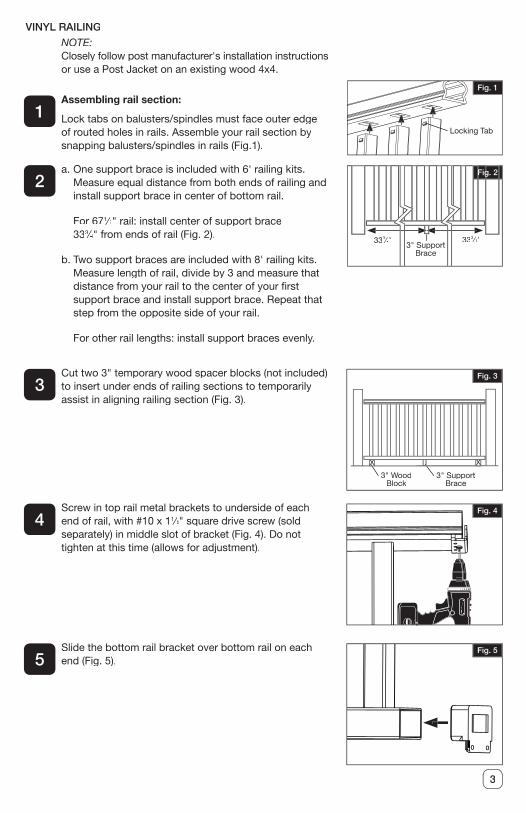
Assembling rail section:
Lock tabs on balusters/spindles must face outer edge of routed holes in rails. Assemble your rail section by snapping balusters/spindles in rails (Fig.1).
a. One support brace is included with 6' railing kits. Measure equal distance from both ends of railing and install support brace in center of bottom rail.
For 671⁄1⁄1 2⁄2⁄ " rail: install center of support brace 333⁄3⁄3 4⁄4⁄ " from ends of rail (Fig. 2).
b. Two support braces are included with 8' railing kits. Measure length of rail, divide by 3 and measure that distance from your rail to the center of your � rst support brace and install support brace. Repeat that step from the opposite side of your rail.
For other rail lengths: install support braces evenly.
NOTE:Closely follow post manufacturer's installation instructions or use a Post Jacket on an existing wood 4x4.
1
2
VINYL RAILING
Fig. 2
333⁄3⁄34⁄4⁄ "
3" Support Brace
333⁄3⁄34⁄4⁄ "
Fig. 1
Locking Tab
Cut two 3" temporary wood spacer blocks (not included)to insert under ends of railing sections to temporarily assist in aligning railing section (Fig. 3).
Screw in top rail metal brackets to underside of each end of rail, with #10 x 11⁄1⁄1 4⁄4⁄ " square drive screw (sold separately) in middle slot of bracket (Fig. 4). Do not tighten at this time (allows for adjustment).
Slide the bottom rail bracket over bottom rail on each end (Fig. 5).
3
4
5
3" Support Brace
3" WoodBlock
Fig. 3
Fig. 4
Fig. 5

4
Fig. 6Slide rail section in-between posts and on top of temporary spacer blocks (position spacer blocks next to installed vinyl posts) (Fig. 6).
6
For Top Brackets:
a. Center rail on post. Then, using a 5⁄5⁄5 32⁄32⁄ " drill bit, pre-drill the � rst hole on an angle though the top rail bracket, vinyl post jacket, and into wood post (or plastic spacer of post install kit) (Fig. 7).
b. Install the #10 x 21⁄1⁄1 2⁄2⁄ "square drive screws (Fig. 8). Looking down from above, check to ensure screws penetrate the wood post (or plastic spacer of post install kit) (Fig. 9).
7
Fig. 9
Fig. 7
Fig. 8
Rail
Screws
Post
PlasticSpacer
Post Install Kit
5
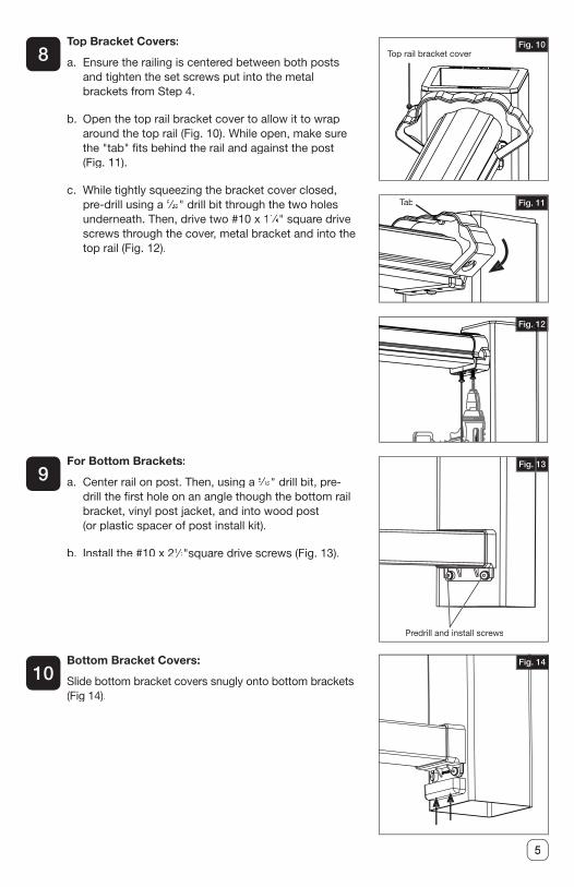
Top Bracket Covers:
a. Ensure the railing is centered between both posts and tighten the set screws put into the metal brackets from Step 4.
b. Open the top rail bracket cover to allow it to wrap around the top rail (Fig. 10). While open, make sure the "tab" � ts behind the rail and against the post (Fig. 11).
c. While tightly squeezing the bracket cover closed, pre-drill using a 5⁄5⁄5 32⁄32⁄ " drill bit through the two holes underneath. Then, drive two #10 x 11⁄1⁄1 4⁄4⁄ " square drive screws through the cover, metal bracket and into the top rail (Fig. 12).
8
Fig. 11
Fig. 10
Fig. 12
Top rail bracket cover
Tab
For Bottom Brackets:
a. Center rail on post. Then, using a 5⁄5⁄5 32⁄32⁄ " drill bit, pre-drill the � rst hole on an angle though the bottom rail bracket, vinyl post jacket, and into wood post (or plastic spacer of post install kit).
b. Install the #10 x 21⁄1⁄1 2⁄2⁄ "square drive screws (Fig. 13).
Bottom Bracket Covers:
Slide bottom bracket covers snugly onto bottom brackets (Fig 14).
9
10
Predrill and install screws
Fig. 13
Fig. 14
6
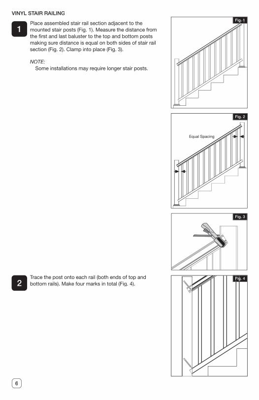
VINYL STAIR RAILING
Place assembled stair rail section adjacent to the mounted stair posts (Fig. 1). Measure the distance from the � rst and last baluster to the top and bottom posts making sure distance is equal on both sides of stair rail section (Fig. 2). Clamp into place (Fig. 3).
NOTE:Some installations may require longer stair posts.
Trace the post onto each rail (both ends of top and bottom rails). Make four marks in total (Fig. 4).
1
2
Equal Spacing
Fig. 1
Fig. 2
Fig. 3
Fig. 4
7
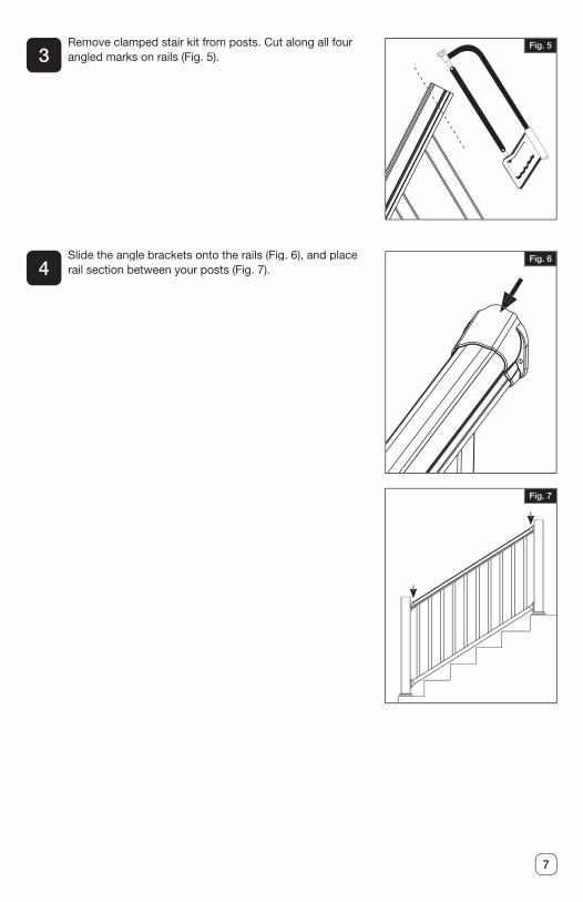
Remove clamped stair kit from posts. Cut along all four angled marks on rails (Fig. 5).
Slide the angle brackets onto the rails (Fig. 6), and place rail section between your posts (Fig. 7).
3
4
Fig. 5
Fig. 6
Fig. 7
8
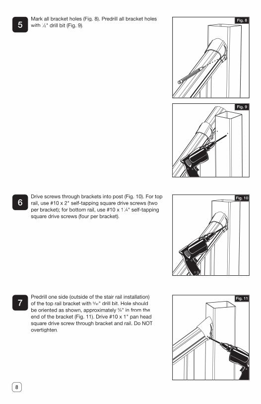
Mark all bracket holes (Fig. 8). Predrill all bracket holes with 1⁄1⁄1 8⁄8⁄ " drill bit (Fig. 9).
Drive screws through brackets into post (Fig. 10). For top rail, use #10 x 2" self-tapping square drive screws (two per bracket); for bottom rail, use #10 x 11⁄1⁄1 4⁄4⁄ " self-tapping square drive screws (four per bracket).
Predrill one side (outside of the stair rail installation) of the top rail bracket with 5⁄5⁄5 32⁄32⁄ " drill bit. Hole should be oriented as shown, approximately 3⁄3⁄3 8⁄8⁄ " in from the end of the bracket (Fig. 11). Drive #10 x 1" pan head square drive screw through bracket and rail. Do NOT overtighten.
5
6
7
Fig. 8
Fig. 9
Fig. 10
Fig. 11
9
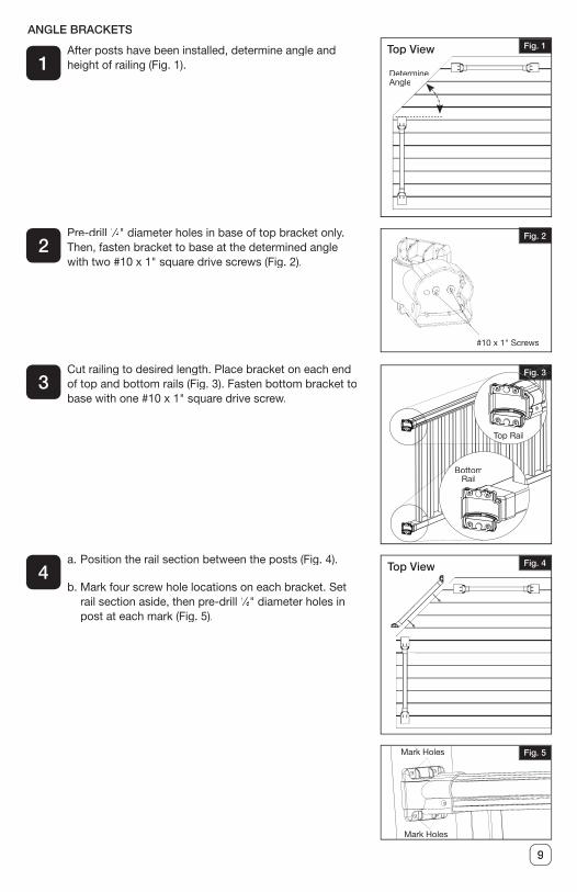
After posts have been installed, determine angle and height of railing (Fig. 1).
Pre-drill 1⁄1⁄1 8⁄8⁄ " diameter holes in base of top bracket only. Then, fasten bracket to base at the determined angle with two #10 x 1" square drive screws (Fig. 2).
Cut railing to desired length. Place bracket on each end of top and bottom rails (Fig. 3). Fasten bottom bracket to base with one #10 x 1" square drive screw.
a. Position the rail section between the posts (Fig. 4).
b. Mark four screw hole locations on each bracket. Set rail section aside, then pre-drill 1⁄1⁄1 8⁄8⁄ " diameter holes in post at each mark (Fig. 5).
1
2
3
4
Fig. 1
Fig. 4
Fig. 5
ANGLE BRACKETS
Determine Angle
Top View
Fig. 2
#10 x 1" Screws
Fig. 3
Top RailTop RailTop Rail
BottomRail
Mark Holes
Mark Holes
Top View
10
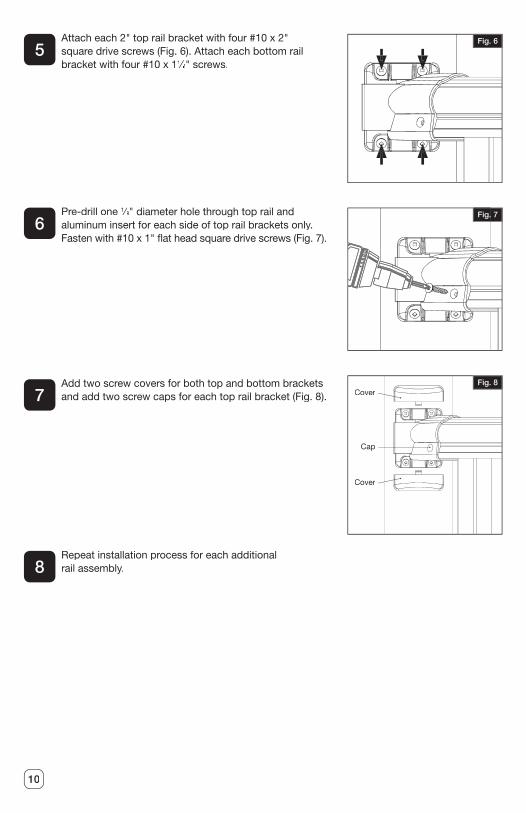
Attach each 2" top rail bracket with four #10 x 2" square drive screws (Fig. 6). Attach each bottom rail bracket with four #10 x 11⁄1⁄1 2⁄2⁄ " screws.
Pre-drill one 1⁄1⁄1 8⁄8⁄ " diameter hole through top rail and aluminum insert for each side of top rail brackets only. Fasten with #10 x 1" � at head square drive screws (Fig. 7).
Add two screw covers for both top and bottom brackets and add two screw caps for each top rail bracket (Fig. 8).
Repeat installation process for each additional rail assembly.
5
6
7
8
Fig. 6
Fig. 7
Fig. 8Cover
Cover
Cap
11
What is covered: Barrette Outdoor Living warrants vinyl and aluminum products to include; vinyl and aluminum fence, vinyl and aluminum railing and plastic lattice against defects or workmanship for as long as you own your home. Barrette Outdoor Living will at its option replace the product in question with new product of the same or equivalent value at no charge. Barrette Outdoor Living warrants these products against peeling, � aking, splintering, corrosion, rusting or abnormal discoloration under normal use and service per ASTMD 2244. This warranty extends to the original purchaser or transferee as speci� ed herein on the products noted above. Separate and distinct warranties for hardware and other products are not covered under this warranty.
What this warranty does not cover: This limited warranty does not cover damage resulting from accident, unreasonable use, neglect, alteration, improper service, improper installation, acts of God or any other causes not arising out of defects in materials or workmanship. Additionally, this warranty does not cover costs of installation, removal, reinstallation or surface mold and mildew created by excessive environmental conditions. Any service or repair provided outside the scope of this limited warranty shall be at Barrette Outdoor Living’s rate and terms then in effect.
What do we do to correct the problems? Should your Barrette Outdoor Living product prove defective under warranty, reference the website or call the phone number listed below. Your problem will be assigned a tracking number and an authorized Barrette Outdoor Living representative will contact you to arrange a convenient time to schedule an onsite inspection, or request pictures, if need be. If after inspection product is deemed to be manufacturer defect we will make arrangements to rectify the issue. You must have proof of your purchase in order for the problem to be corrected.
Transferee Coverage: Warranty coverage will be extended to one transferee on the above listed products with the following limitations. Transferee must obtain an original or copy of the initial sales receipt (with proof of date) from the previous owner(s). Additionally, if fence is purchased from a builder or installer, documentation must be supplied that names the product installed on property and date of transfer.
THIS WARRANTY IS IN LIEU OF ALL CONDITIONS OR WARRANTIES, EXPRESS OR IMPLIED, INCLUDING BUT NOT LIMITED TO ANY IMPLIED CONDITIONS OR WARRANTIES OR MERCHANTABILITY OR FITNESS FOR A PARTICULAR PURPOSE ON THE PART OF BARRETTE OR ITS LICENSORS, SOME STATES DO NOT ALLOW THE EXCLUSIONS OF IMPLIED WARRANTIES OR LIMITATIONS OF HOW LONG AN IMPLIED WARRANTY LASTS, SO THE ABOVE LIMITATIONS MAY NOT APPLY TO YOU. IF THE PRODUCT IS DEFECTIVE PER THE ABOVE COVERAGES, YOUR SOLE AND EXCLUSIVE REMEDY SHALL BE REPAIR OR REPLACEMENT AS PROVIDED ABOVE. BARRETTE AND ITS LICENSORS SHALL NOT BE LIABLE FOR ANY DAMAGES, LOSS OF USE, LOSS OF PROFITS OR INTERRUPTION OF BUSINESS WHETHER SUCH ALLEGED DAMAGES ARE BASED IN WARRANTY, TORT, CONTRACT, OR INDEMNITY. SOME STATES DO NOT ALLOW THE EXCLUSION OF LIMITATIONS OF INCIDENTAL OR CONSEQUENTIAL DAMAGES, SO THE ABOVE LIMITATIONS MAY NOT APPLY TO YOU. THIS WARRANTY IS VALID ONLY IN THE UNITED STATES AND CANADA.
For any speci� c questions about the Barrette Outdoor Living Warranty please contact Barrette Outdoor Living by visiting our website www.barretteoutdoorliving.com, emailing or calling 1-800-336-2383.
To begin your warranty coverage and register your product visit: www.barretteoutdoorliving.com. Retain manual and your dated sales slip for future reference or warranty claims.
Transferable Limited Lifetime Warranty

12
INSTRUCCIONES DE INSTALACIÓN
Barandal de vinilo y barandal de escalerasPara los estilos Traditional y Williamsburg
34107310BOM
Lea todas las instrucciones antes de la instalación del producto.
Consulte las instrucciones de seguridad del fabricante al utilizar herramientas.
Para registrar su producto, visite:Para registrar su producto, visite:
veranda.barretteoutdoorliving.com
• English ..............................................................................1
• Español ...........................................................................12
14
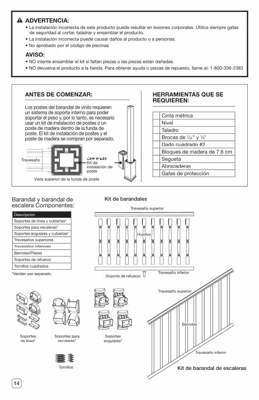
Cinta métricaNivelTaladroBrocas de 5⁄5⁄5 32⁄32⁄ " y 1⁄1⁄1 8⁄8⁄ "Dado cuadrado #2Bloques de madera de 7.6 cmSeguetaAbrazaderasGafas de protección
HERRAMIENTAS QUE SE REQUIEREN:
ANTES DE COMENZAR:
ADVERTENCIA:• La instalación incorrecta de este producto puede resultar en lesiones corporales. Utilice siempre gafas
de seguridad al cortar, taladrar y ensamblar el producto.• La instalación incorrecta puede causar daños al producto o a personas.• No aprobado por el código de piscinas
AVISO:• NO intente ensamblar el kit si faltan piezas o las piezas están dañadas.• NO devuelva el producto a la tienda. Para obtener ayuda o piezas de repuesto, llame al: 1-800-336-2383
Barandal y barandal de escalera Componentes:
*Venden por separado.
Descripción
Soportes de línea y cubiertas*
Soportes para escaleras*
Soportes angulares y cubiertas*
Travesaños superiores
Travesaños inferiores
Barrotes/Pilares
Soportes de refuerzo
Tornillos cuadrados
Los postes del barandal de vinilo requieren un sistema de soporte interno para poder soportar el peso y, por lo tanto, es necesario usar un kit de instalación de postes o un poste de madera dentro de la funda de poste. El kit de instalación de postes y el poste de madera se compran por separado.
Vista superior de la funda de posteVista superior de la funda de poste
TravesañoTravesañoTravesañoTravesañoTravesañoTravesañoTravesañoTravesañoTravesaño CompradoKit de instalación de poste
Soportes de línea*
Travesaño superior
Travesaño inferiorSoporte de refuerzo
HusillosHusillosHusillosHusillosHusillosHusillosHusillos
Travesaño superior
Travesaño inferior
BarrotesBarrotesBarrotesBarrotesBarrotesBarrotesBarrotesBarrotesBarrotesBarrotesBarrotesBarrotes
Soportes para escaleras*
Kit de barandales
Kit de barandal de escaleras
Soportes angulares*
Tornillos
15
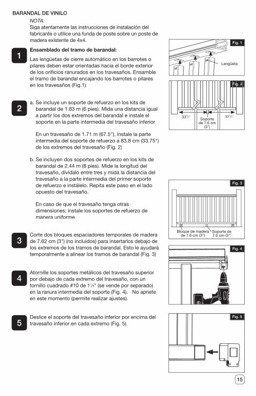
Ensamblado del tramo de barandal:
Las lengüetas de cierre automático en los barrotes o pilares deben estar orientadas hacia el borde exterior de los ori� cios ranurados en los travesaños. Ensamble el tramo de barandal encajando los barrotes o pilares en los travesaños (Fig.1).
a. Se incluye un soporte de refuerzo en los kits de barandal de 1.83 m (6 pies). Mida una distancia igual a partir los dos extremos del barandal e instale el soporte en la parte intermedia del travesaño inferior
En un travesaño de 1.71 m (67.5"), instale la parte intermedia del soporte de refuerzo a 83.8 cm (33.75") de los extremos del travesaño (Fig. 2)
b. Se incluyen dos soportes de refuerzo en los kits de barandal de 2.44 m (8 pies). Mide la longitud del travesaño, divídalo entre tres y mida la distancia del travesaño a la parte intermedia del primer soporte de refuerzo e instálelo. Repita este paso en el lado opuesto del travesaño.
En caso de que el travesaño tenga otras dimensiones: instale los soportes de refuerzo de manera uniforme.
NOTA:Siga atentamente las instrucciones de instalación del fabricante o utilice una funda de poste sobre un poste de madera existente de 4x4.
1
2
BARANDAL DE VINILO
Fig. 2
333⁄3⁄34⁄4⁄ " Soporte
de 7.6 cm (3")
333⁄3⁄34⁄4⁄ "
Fig. 1
Lengüeta
Corte dos bloques espaciadores temporales de madera de 7.62 cm (3") (no incluidos) para insertarlos debajo de los extremos de los tramos de barandal. Esto le ayudará temporalmente a alinear los tramos de barandal (Fig. 3)
Atornille los soportes metálicos del travesaño superior por debajo de cada extremo del travesaño, con un tornillo cuadrado #10 de 11⁄1⁄1 4⁄4⁄ " (se vende por separado) en la ranura intermedia del soporte (Fig. 4). No apriete en este momento (permite realizar ajustes).
Deslice el soporte del travesaño inferior por encima del travesaño inferior en cada extremo (Fig. 5).
3
4
5
Soporte de 7.6 cm (3")
Bloque de madera de 7.6 cm (3")
Fig. 3
Fig. 4
Fig. 5
16
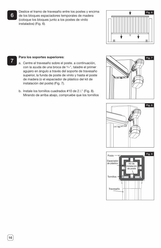
Fig. 6Deslice el tramo de travesaño entre los postes y encima de los bloques espaciadores temporales de madera (coloque los bloques junto a los postes de vinilo instalados) (Fig. 6).
6
Para los soportes superiores:
a. Centre el travesaño sobre el poste. a continuación, con la ayuda de una broca de 5⁄5⁄5 32⁄32⁄ ", taladre el primer agujero en ángulo a través del soporte de travesaño superior, la funda de poste de vinilo y hasta el poste de madera (o el espaciador de plástico del kit de instalación del poste) (Fig. 7).
b. Instale los tornillos cuadrados #10 de 21⁄1⁄1 2⁄2⁄ " (Fig. 8). Mirando de arriba abajo, compruebe que los tornillos
7
Fig. 9
Fig. 7
Fig. 8
Travesaño
Tornillos
Poste
Espaciador de plástico Kit de
instalación de poste
17
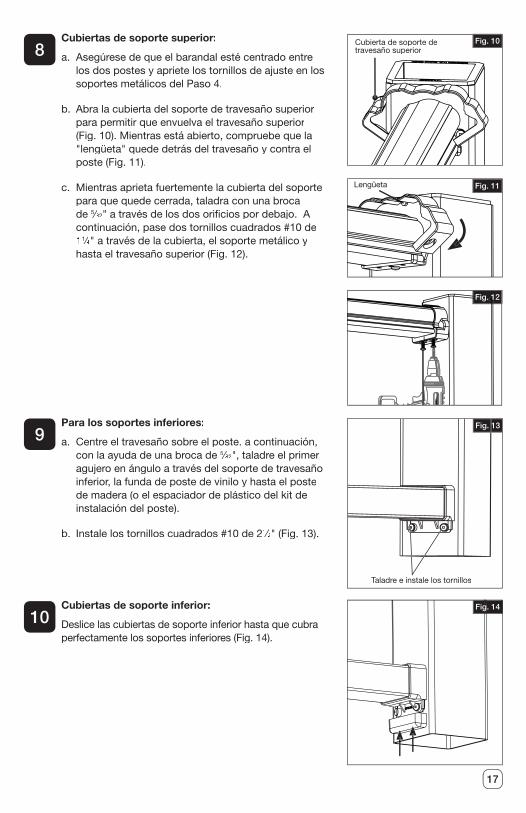
Cubiertas de soporte superior:
a. Asegúrese de que el barandal esté centrado entre los dos postes y apriete los tornillos de ajuste en los soportes metálicos del Paso 4.
b. Abra la cubierta del soporte de travesaño superior para permitir que envuelva el travesaño superior (Fig. 10). Mientras está abierto, compruebe que la "lengüeta" quede detrás del travesaño y contra el poste (Fig. 11).
c. Mientras aprieta fuertemente la cubierta del soporte para que quede cerrada, taladra con una broca de 5⁄5⁄5 32⁄32⁄ " a través de los dos ori� cios por debajo. A continuación, pase dos tornillos cuadrados #10 de 11⁄1⁄1 4⁄4⁄ " a través de la cubierta, el soporte metálico y hasta el travesaño superior (Fig. 12).
8
Fig. 11
Fig. 10
Fig. 12
Cubierta de soporte de travesaño superior
Lengüeta
Para los soportes inferiores:
a. Centre el travesaño sobre el poste. a continuación, con la ayuda de una broca de 5⁄5⁄5 32⁄32⁄ ", taladre el primer agujero en ángulo a través del soporte de travesaño inferior, la funda de poste de vinilo y hasta el poste de madera (o el espaciador de plástico del kit de instalación del poste).
b. Instale los tornillos cuadrados #10 de 21⁄1⁄1 2⁄2⁄ " (Fig. 13).
Cubiertas de soporte inferior:
Deslice las cubiertas de soporte inferior hasta que cubra perfectamente los soportes inferiores (Fig. 14).
9
10
Taladre e instale los tornillos
Fig. 13
Fig. 14
18
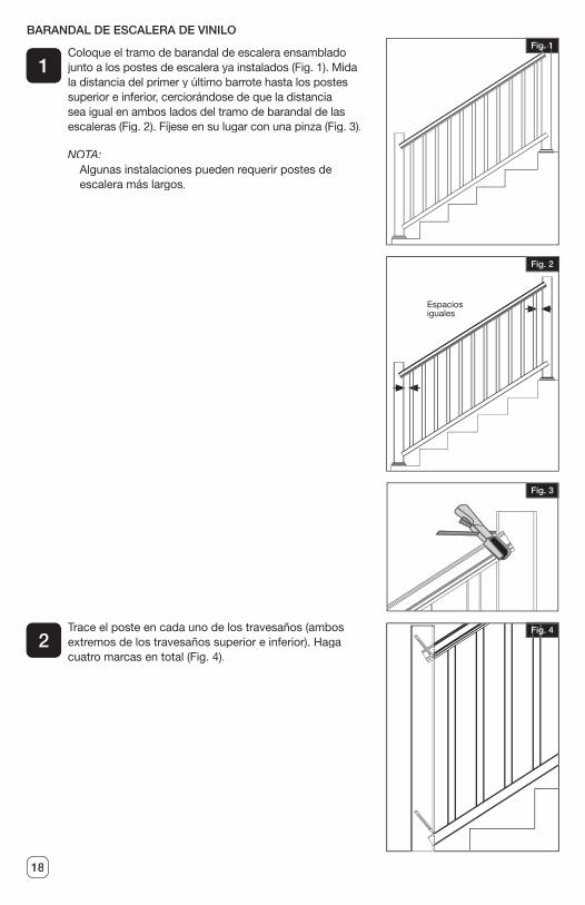
BARANDAL DE ESCALERA DE VINILO
Coloque el tramo de barandal de escalera ensamblado junto a los postes de escalera ya instalados (Fig. 1). Mida la distancia del primer y último barrote hasta los postes superior e inferior, cerciorándose de que la distancia sea igual en ambos lados del tramo de barandal de las escaleras (Fig. 2). Fíjese en su lugar con una pinza (Fig. 3).
NOTA:Algunas instalaciones pueden requerir postes de escalera más largos.
Trace el poste en cada uno de los travesaños (ambos extremos de los travesaños superior e inferior). Haga cuatro marcas en total (Fig. 4).
1
2
Espacios iguales
Fig. 1
Fig. 2
Fig. 3
Fig. 4
19
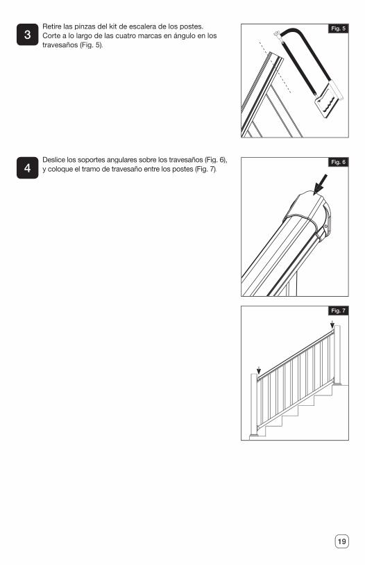
Retire las pinzas del kit de escalera de los postes. Corte a lo largo de las cuatro marcas en ángulo en los travesaños (Fig. 5).
Deslice los soportes angulares sobre los travesaños (Fig. 6), y coloque el tramo de travesaño entre los postes (Fig. 7).
3
4
Fig. 5
Fig. 6
Fig. 7
20
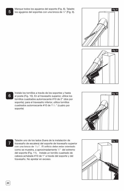
Marque todos los agujeros del soporte (Fig. 8). Taladre los agujeros del soportes con una broca de 1⁄1⁄1 8⁄8⁄ " (Fig. 9).
Instale los tornillos a través de los soportes y hasta el poste (Fig. 10). En el travesaño superior, utilice los tornillos cuadrados autorroscante #10 de 2" (dos por soporte); para el travesaño inferior, utilice tornillos cuadrados autorroscante #10 de 11 ⁄1 ⁄1 4⁄ 4⁄ " (cuatro por soporte)
Taladre uno de los lados (fuera de la instalación de travesaño de escalera) del soporte de travesaño superior con una broca de 5 ⁄ 5 ⁄ 5 32⁄ 32⁄ ". El ori� cio debe estar orientado como se muestra, a aproximadamente 3⁄3⁄3 8⁄8⁄ " del extremo del soporte (Fig. 11). Instale un tornillo cuadrado de cabeza achatada #10 de 1" a través del soporte y del travesaño. No apretar en exceso.
5
6
7
Fig. 8
Fig. 9
Fig. 10
Fig. 11
21
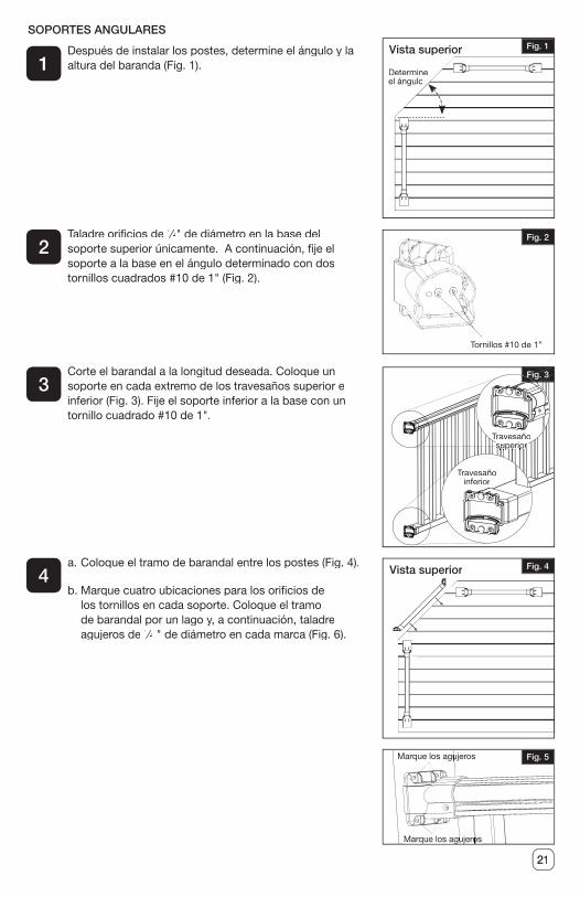
Después de instalar los postes, determine el ángulo y la altura del baranda (Fig. 1).
Taladre ori� cios de 1⁄1⁄1 8⁄8⁄ " de diámetro en la base del soporte superior únicamente. A continuación, � je el soporte a la base en el ángulo determinado con dos tornillos cuadrados #10 de 1" (Fig. 2).
Corte el barandal a la longitud deseada. Coloque un soporte en cada extremo de los travesaños superior e inferior (Fig. 3). Fije el soporte inferior a la base con un tornillo cuadrado #10 de 1".
a. Coloque el tramo de barandal entre los postes (Fig. 4).
b. Marque cuatro ubicaciones para los ori� cios de los tornillos en cada soporte. Coloque el tramo de barandal por un lago y, a continuación, taladre agujeros de 1⁄1⁄1 8⁄8⁄ " de diámetro en cada marca (Fig. 6).
1
2
3
4
Fig. 1
Fig. 4
Fig. 5
SOPORTES ANGULARES
Determine el ángulo
Vista superior
Fig. 2
Tornillos #10 de 1”
Fig. 3
Travesaño Travesaño superiorsuperiorsuperiorsuperiorsuperiorsuperiorsuperiorsuperiorsuperiorsuperiorsuperiorsuperiorsuperiorsuperiorsuperiorsuperiorsuperiorsuperiorsuperiorsuperiorsuperiorsuperiorsuperiorsuperiorsuperiorsuperiorsuperiorsuperiorsuperiorsuperior
Travesaño inferior
Marque los agujerosMarque los agujeros
Marque los agujerosMarque los agujerosMarque los agujerosMarque los agujeros
Vista superior
22
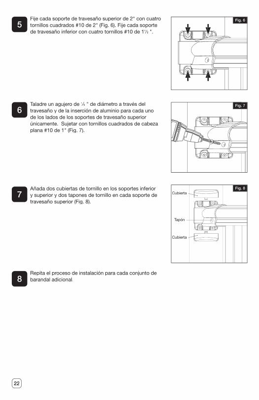
Fije cada soporte de travesaño superior de 2" con cuatro tornillos cuadrados #10 de 2" (Fig. 6). Fije cada soporte de travesaño inferior con cuatro tornillos #10 de 11⁄1⁄1 2⁄2⁄ ".
Taladre un agujero de 1⁄1⁄1 8⁄8⁄ " de diámetro a través del travesaño y de la inserción de aluminio para cada uno de los lados de los soportes de travesaño superior únicamente. Sujetar con tornillos cuadrados de cabeza plana #10 de 1" (Fig. 7).
Añada dos cubiertas de tornillo en los soportes inferior y superior y dos tapones de tornillo en cada soporte de travesaño superior (Fig. 8).
Repita el proceso de instalación para cada conjunto de barandal adicional.
5
6
7
8
Fig. 6
Fig. 7
Fig. 8Cubierta
Cubierta
Tapón
23
Cuál es su cobertura: Barrette Outdoor Living garantiza los productos de vinilo y aluminio, que incluyen vallas de vinilo y aluminio, travesaños de vinilo y aluminio, y celosías de plástico, contra defectos de materiales o mano de obra mientras sea propietario de su residencia. Barrette Outdoor Living, a su discreción, reemplazará el producto en cuestión con un producto nuevo del mismo valor o de valor equivalente sin costo alguno. Barrette Outdoor Living garantiza estos productos contra descarapelado, desconchado, astillado, oxidación, corrosión o decoloración anormal bajo uso y servicio normal, de conformidad con la norma ASTMD 2244. Esta garantía se extiende al comprador original o al cesionario como se especi� ca aquí sobre los productos mencionados anteriormente. Esta garantía no cubre otras garantías separadas y singulares para componentes y otros productos.
Qué no está cubierto por esta garantía: Esta garantía limitada no cubre daños que resulten de un accidente, uso irrazonable, negligencia, alteración, servicio inadecuado, instalación inadecuada, casos de fuerza mayor o cualquier otra causa que no surja de defectos de los materiales o de la mano de obra. Además, esta garantía no cubre costos de instalación, remoción, reinstalación ni enmohecimiento creado por condiciones ambientales excesivas. Para los servicios o reparaciones proporcionadas fuera del alcance de esta garantía limitada aplicarán las tarifas y términos vigentes de Barrette Outdoor Living.
¿Qué podemos hacer para corregir los problemas? En caso de que el producto de Barrette Outdoor Living salga defectuoso bajo la garantía, consulte el sitio web o llame al número de teléfono indicado abajo. El problema recibirá un número de seguimiento y un representante autorizado de Barrette Outdoor Living le contactará para programar una hora conveniente para una inspección en el lugar, o solicitar fotos, si se requiere. Si después de la inspección se considera que el producto tiene un defecto de fabricación, haremos arreglos para recti� car el problema. Debe tener un comprobante de compra para que se corrija el problema.
Cobertura del cesionario: La cobertura de la garantía se extenderá a un cesionario para los productos indicados anteriormente, con las siguientes limitantes. El cesionario debe obtener una copia o el original del recibo inicial de venta (con comprobante de fecha) de los propietarios anteriores. Además, si compró la valla a una constructora o instalador, se debe proveer la documentación donde se indiquen los nombres del producto instalado en la propiedad y la fecha de transferencia.
ESTA GARANTÍA SUSTITUYE TODAS LAS CONDICIONES O GARANTÍAS, EXPRESAS O IMPLÍCITAS, INCLUSIVE, ENTRE OTRAS, CONDICIONES O GARANTÍAS IMPLÍCITAS ESTA GARANTÍA SUSTITUYE TODAS LAS CONDICIONES O GARANTÍAS, EXPRESAS O IMPLÍCITAS, INCLUSIVE, ENTRE OTRAS, CONDICIONES O GARANTÍAS IMPLÍCITAS ESTA GARANTÍA SUSTITUYE TODAS LAS CONDICIONES O GARANTÍAS, EXPRESAS
O COMERCIABILIDAD O IDONEIDAD PARA UN FIN EN PARTICULAR POR PARTE DE BARRETTE O SUS CONCESIONARIOS. ALGUNOS ESTADOS NO PERMITEN LA EXCLUSIÓN DE GARANTÍAS IMPLÍCITAS NI LAS LIMITACIONES SOBRE EL TIEMPO QUE PUEDE DURAR UNA GARANTÍA IMPLÍCITA, DE MODO QUE ES POSIBLE QUE LAS LIMITACIONES NO APLIQUEN A USTED. SI EL PRODUCTO ESTÁ DEFECTUOSO QUE PUEDE DURAR UNA GARANTÍA IMPLÍCITA, DE MODO QUE ES POSIBLE QUE LAS LIMITACIONES NO APLIQUEN A USTED. SI EL PRODUCTO ESTÁ DEFECTUOSO QUE PUEDE DURAR UNA GARANTÍA IMPLÍCITA, DE MODO QUE ES POSIBLE QUE
SEGÚN LAS COBERTURAS ANTERIORES, SU ÚNICO Y EXCLUSIVO REMEDIO ES LA REPARACIÓN O EL REEMPLAZO COMO SE INDICA ANTERIORMENTE. BARRETTE SEGÚN LAS COBERTURAS ANTERIORES, SU ÚNICO Y EXCLUSIVO REMEDIO ES LA REPARACIÓN O EL REEMPLAZO COMO SE INDICA ANTERIORMENTE. BARRETTE SEGÚN LAS COBERTURAS ANTERIORES, SU ÚNICO Y EXCLUSIVO REMEDIO ES LA
Y SUS CONCESIONARIOS NO SON LEGALMENTE RESPONSABLES DE DAÑOS, PÉRDIDAS DE USO, PÉRDIDAS DE GANANCIAS O INTERRUPCIONES COMERCIALES, Y SUS CONCESIONARIOS NO SON LEGALMENTE RESPONSABLES DE DAÑOS, PÉRDIDAS DE USO, PÉRDIDAS DE GANANCIAS O INTERRUPCIONES COMERCIALES, Y SUS CONCESIONARIOS NO SON LEGALMENTE RESPONSABLES DE DAÑOS,
SIN IMPORTAR SI LOS SUPUESTOS DAÑOS SE BASAN EN UNA GARANTÍA, AGRAVIO, PÉRDIDAS DE USO, PÉRDIDAS DE GANANCIAS O INTERRUPCIONES COMERCIALES, SIN IMPORTAR SI LOS SUPUESTOS DAÑOS SE BASAN EN UNA GARANTÍA, AGRAVIO, PÉRDIDAS DE USO, PÉRDIDAS DE GANANCIAS O INTERRUPCIONES COMERCIALES,
CONTRATO O INDEMNIZACIÓN. ALGUNOS ESTADOS NO PERMITEN LA EXCLUSIÓN SIN IMPORTAR SI LOS SUPUESTOS DAÑOS SE BASAN EN UNA GARANTÍA, AGRAVIO, CONTRATO O INDEMNIZACIÓN. ALGUNOS ESTADOS NO PERMITEN LA EXCLUSIÓN SIN IMPORTAR SI LOS SUPUESTOS DAÑOS SE BASAN EN UNA GARANTÍA, AGRAVIO,
O LIMITACIÓN DE DAÑOS INCIDENTALES O CONSECUENTES, DE MODO QUE ES POSIBLE QUE LAS LIMITACIONES NO APLIQUEN A USTED. ESTA GARANTÍA O LIMITACIÓN DE DAÑOS INCIDENTALES O CONSECUENTES, DE MODO QUE
ESTA GARANTÍA O LIMITACIÓN DE DAÑOS INCIDENTALES O CONSECUENTES, DE MODO QUE
SOLAMENTE ES VÁLIDA EN LOS ESTADOS UNIDOS Y CANADÁ.
Para preguntas especí� cas sobre la Garantía de Barrette Outdoor Living, contacte a Barrette Outdoor Living visitando nuestro sitio web www.barretteoutdoorliving.com, enviando un mensaje electrónico o llamando al 1-800-336-2383.
Comience la cobertura de la garantía y registre su producto de Barrette Outdoor Living en www.BarretteOutdoorLiving.com. Conserver le manuel et votre reçu de caisse datépour de futures références ou de réclamations de garantie. Conserve el manual y susventas anticuadas se deslizan para las demandas futuras de la referencia o de la garantía.
Garantía de por vida limitada y transferible

BARRETTE OUTDOOR LIVING
7830 FREEWAY CIRCLEMIDDLEBURG HEIGHTS, OHIO 44130
TEL: (800) 336-2383WWW.VERANDA.BARRETTEOUTDOORLIVING.COM