
Great Falls Hydroelectric Project FERC Project Number 2814-025
18
Application for New License EXHIBIT A – PROJECT DESCRIPTION Great Falls Hydroelectric Project FERC Project Number 2814-025 City of Paterson, NJ and Great Falls Hydroelectric Company August 2019
Transcript of Great Falls Hydroelectric Project FERC Project Number 2814-025

Application for New License
EXHIBIT A – PROJECT DESCRIPTION
Great Falls Hydroelectric Project
FERC Project Number 2814-025
City of Paterson, NJ and Great Falls Hydroelectric Company
August 2019
Great Falls Hydroelectric Project: P-2814 Exhibit A – Project Description Application for New License
________________________________________________________________________________________________ YES © 2019 Young Energy Services August 2019
A - i
Table of Contents
A – 1.0 PROJECT DESCRIPTION ........................................................................................................... 1
INTRODUCTION .................................................................................................................................... 1
1.1 PROJECT LOCATION ............................................................................................................................ 1
A – 2.0 PROJECT FEATURES ................................................................................................................. 3
2.1 EXISTING PROJECT OPERATIONS ........................................................................................................... 3 2.2 GENERATOR AND TURBINE .................................................................................................................. 3 2.3 IMPOUNDMENT ................................................................................................................................ 4 2.4 ESTIMATED GROSS HEAD .................................................................................................................... 5 2.5 BYPASS REACH ................................................................................................................................. 5 2.6 PROJECT FACILITIES AND COMPONENTS ................................................................................................... 5 2.6.1 POWERHOUSE, CONTROL ROOM, SUBSTATION, AND SWITCHYARD .................................................................. 5 2.6.2 S.U.M. DAM AND SPILLWAY ..................................................................................................................... 6 2.6.3 TRANSMISSION LINES ............................................................................................................................... 6 2.6.4 WATER CONDUITS ................................................................................................................................... 7 2.6.5 FOREBAY ................................................................................................................................................ 7 2.7 PROJECT COST ................................................................................................................................... 7 2.8 ESTIMATED PROJECT OPERATIONS AND MAINTENANCE COSTS OF EACH PROPOSED ENVIRONMENTAL MEASURE ..... 7
A – 3.0 PROJECT PURPOSE .................................................................................................................. 8
3.1 PROJECT LICENSING COSTS .................................................................................................................... 8
A – 4.0 PEAK AND OFF-PEAK POWER VALUES ..................................................................................... 9
A – 5.0 CHANGES IN PROJECT GENERATION ...................................................................................... 10
A – 6.0 PROJECT VALUE .................................................................................................................... 11
A – 7.0 ANNUAL OPERATIONS AND MAINTENANCE COSTS ............................................................... 12
A – 8.0 ELECTRICAL DIAGRAM .......................................................................................................... 13
A – 9.0 SAFE MANAGEMENT, OPERATION, AND MAINTENANCE OF THE PROJECT ............................ 14
A – 10.0 REFERENCES ........................................................................................................................ 15

Great Falls Hydroelectric Project: P-2814 Exhibit A – Project Description Application for New License
________________________________________________________________________________________________ YES © 2019 Young Energy Services August 2019
A - ii
List of Tables Table 2.2.1: Project Turbine Units 3 Table 2.2.2: Project Generator Units 4 Table 2.3.1: Reservoir Characteristics 4
List of Figures Figure 1.1: Project Facilities 2

Great Falls Hydroelectric Project: P-2814 Exhibit A – Project Description Application for New License
________________________________________________________________________________________________ YES © 2019 Young Energy Services August 2019
A - 1
A – 1.0 PROJECT DESCRIPTION The following excerpt from the Code of Federal Regulations (CFR) at 18 CFR § 4.51(b) describes the required content of this Exhibit. Exhibit A is a description of the project. This exhibit need not include information on project works maintained and operated by the U.S. Army Corps of Engineers, the Bureau of Reclamation, or any other department or agency of the United States, except for any project works that are proposed to be altered or modified. If the project includes more than one dam with associated facilities, each dam and the associated component parts must be described together as a discrete development. 18 CFR §5.6(d)(2) requires a "detailed description of all existing and proposed project facilities and components; Physical composition, dimensions, general configuration of any dams, spillways, penstocks, canals, powerhouses, tailraces and other structures proposed to be included as part of the project or connected directly to it; normal maximum water surface area and normal maximum water surface elevation mean sea level (msl), gross storage capacity of any impoundments."
INTRODUCTION This Exhibit A is a description of the Great Falls Hydroelectric Project (Project). Agency and stakeholder consultation with the appropriate agencies was initiated in 2016, as required by the Federal Energy Regulatory Commission (FERC), and commenced with submittal of the Pre-Application Document (PAD). Subsequent to the issuance of the PAD, a stakeholder meeting was held August 3, 2016. A transcript of the meeting is presented in Appendix C. The Applicants identified issues that must be addressed during the relicensing process, have conducted appropriate studies related to the aesthetic flows, and have performed project-related studies to define the proposed changes to the Project Boundary, night time flows, and flashboard reinstallation.
1.1 Project Location The 10,935 kilowatt (kW) Great Falls Hydroelectric Project is located in Passaic County on the Passaic River in the city of Paterson, New Jersey. The present Project Boundary encompasses roughly 152 acres in the central-northwest portion of Paterson. The Project lies within the Great Falls Historic District, which has been a national industrial landmark since 1971. Figure 1.1 presents the current Project Boundary and identifies major Project facilities.

Great Falls Hydroelectric Project: P-2814 Exhibit A – Project Description Application for New License
________________________________________________________________________________________________ YES © 2019 Young Energy Services August 2019
A - 2
Great Falls Hydroelectric Project P-2814 Figure 1.1: Project Facilities
Project Boundary
Map Developed using the best available public sources.
NOVEMBER 2018
EAGLE CREEK RENEWABLE ENERGY
AREA OF DETAIL Great Falls Hydroelectric Project
FERC P-2814
S.U.M. Dam
Great Falls
Powerhouse

Great Falls Hydroelectric Project: P-2814 Exhibit A - Project Description Application for New License
________________________________________________________________________________________________ YES © 2019 Young Energy Services August 2019
A - 3
A – 2.0 PROJECT FEATURES 2.1 Existing Project Operations A description of any changes to existing Project operations. The Great Falls power station is a 10,935-kW hydroelectric generating station located at the base of Great Falls, the second-largest waterfall by volume east of the Mississippi River in Paterson, New Jersey. The current hydroelectric powerhouse was completed in 1914 and operated with its original equipment until 1969. The facility’s three vertical Kaplan turbine generators were installed in 1986 and can produce approximately 30 million kilowatt hours (kWh) of clean energy in a typical year. It was declared a National Historic Landmark in 1976 and became a National Historical Park in 2011. The Project works approved as part of the current FERC License consist of: (a) The Society for the Establishment of Useful Manufactures (S.U.M.) Dam, an overflow granite stone gravity structure approximately 315 feet long, with a maximum height of 15 feet and having a spillway crest elevation of 114.6 feet mean sea level (msl) or 113.9 feet North American Vertical Datum of 1988 (NAVD) and 27 inch (2.25 foot) breakaway flashboards; (b) a forebay inlet structure; (c) a reservoir with negligible storage at top of flashboards crest elevation 116.85 feet (msl), or 116.15 feet (NAVD); (d) a walkway, bridge, and a trash diverter; (e) a headgate control structure containing three trashracks 16’ 8-1/2” tall x 59’ 3” wide with automatic cleaners, 2” clear bar spacing, and three 96” x 96” steel gates; (f) three penstocks, each 8.5 feet in diameter and approximately 55 feet long; (g) a concrete powerhouse containing three turbine/generators with a total rated capacity of 10.95 megawatts (MW); (h) a 37 foot-long, 4.16 kilovolt (kV) underground cable connecting the powerhouse to a 4.16/26.4 kV step-up transformer, tying into the local Public Service Electric and Gas Company (PSE&G) 26.4 kV distribution network via an approximately 30-foot-long, 26.4 kV underground cable; and (i) other appurtenant facilities.
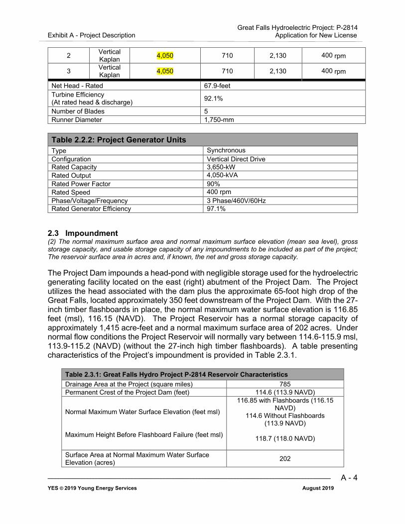
2.2 Generator and Turbine The number, type, and rated capacity of any turbines or generators, whether existing or proposed, to be included as part of the project. The Project has an authorized installed capacity of 10,935 kW and contains three vertical shaft Kaplan double regulated, tube type turbine generators with adjustable wicket gates and blades. Each generator has a rated output of 4,050 kilovolt amperes and a power factor of 90 percent. Table 2.2.1 summarizes the current turbine units at the Project and Table 2.2.2 presents information regarding the Project generators. Table 2.2.1: Project Turbine Units
Turbine Number Turbine
Rated Output [Rated Net Head]
(kilovolt Amperes)
Rated Discharge
(cfs) Plant Flow
(cfs) Operating Speed
1 Vertical Kaplan 4,050 710 2,130 400 rpm
Great Falls Hydroelectric Project: P-2814 Exhibit A - Project Description Application for New License
________________________________________________________________________________________________ YES © 2019 Young Energy Services August 2019
A - 4
2 Vertical Kaplan 4,050 710 2,130 400 rpm
3 Vertical Kaplan 4,050 710 2,130 400 rpm
Net Head - Rated 67.9-feet Turbine Efficiency (At rated head & discharge) 92.1%
Number of Blades 5 Runner Diameter 1,750-mm
Table 2.2.2: Project Generator Units Type Synchronous Configuration Vertical Direct Drive Rated Capacity 3,650-kW Rated Output 4,050-kVA Rated Power Factor 90% Rated Speed 400 rpm Phase/Voltage/Frequency 3 Phase/460V/60Hz Rated Generator Efficiency 97.1%
2.3 Impoundment (2) The normal maximum surface area and normal maximum surface elevation (mean sea level), gross storage capacity, and usable storage capacity of any impoundments to be included as part of the project; The reservoir surface area in acres and, if known, the net and gross storage capacity. The Project Dam impounds a head-pond with negligible storage used for the hydroelectric generating facility located on the east (right) abutment of the Project Dam. The Project utilizes the head associated with the dam plus the approximate 65-foot high drop of the Great Falls, located approximately 350 feet downstream of the Project Dam. With the 27-inch timber flashboards in place, the normal maximum water surface elevation is 116.85 feet (msl), 116.15 (NAVD). The Project Reservoir has a normal storage capacity of approximately 1,415 acre-feet and a normal maximum surface area of 202 acres. Under normal flow conditions the Project Reservoir will normally vary between 114.6-115.9 msl, 113.9-115.2 (NAVD) (without the 27-inch high timber flashboards). A table presenting characteristics of the Project’s impoundment is provided in Table 2.3.1.
Table 2.3.1: Great Falls Hydro Project P-2814 Reservoir Characteristics Drainage Area at the Project (square miles) 785 Permanent Crest of the Project Dam (feet) 114.6 (113.9 NAVD)
Normal Maximum Water Surface Elevation (feet msl) Maximum Height Before Flashboard Failure (feet msl)
116.85 with Flashboards (116.15 NAVD)
114.6 Without Flashboards (113.9 NAVD)
118.7 (118.0 NAVD)
Surface Area at Normal Maximum Water Surface Elevation (acres) 202
Great Falls Hydroelectric Project: P-2814 Exhibit A - Project Description Application for New License
________________________________________________________________________________________________ YES © 2019 Young Energy Services August 2019
A - 5
Table 2.3.1: Great Falls Hydro Project P-2814 Reservoir Characteristics Maximum Storage Capacity (acre-feet) 1,415
2.4 Estimated Gross Head The estimated average head on the plant. The site develops an estimated 77 feet of gross head.
2.5 Bypass Reach The Applicants propose that the area downstream of the S.U.M. Dam be removed from the Project area, therefore eliminating any bypass reach associated with the Project.
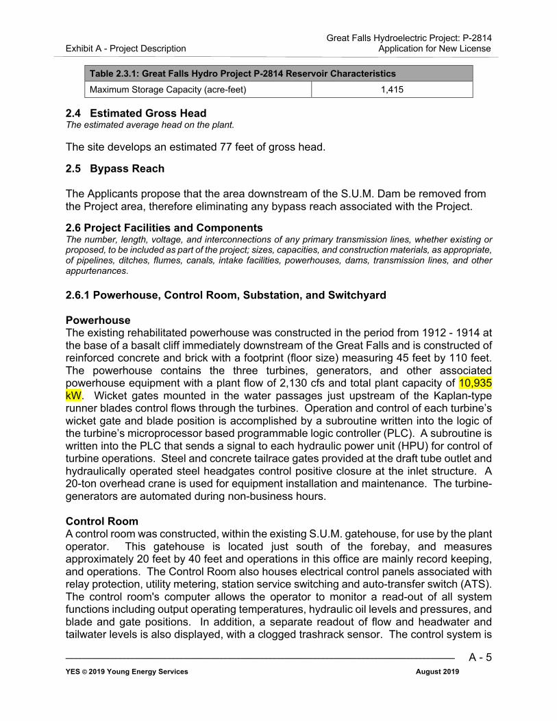
2.6 Project Facilities and Components The number, length, voltage, and interconnections of any primary transmission lines, whether existing or proposed, to be included as part of the project; sizes, capacities, and construction materials, as appropriate, of pipelines, ditches, flumes, canals, intake facilities, powerhouses, dams, transmission lines, and other appurtenances. 2.6.1 Powerhouse, Control Room, Substation, and Switchyard Powerhouse The existing rehabilitated powerhouse was constructed in the period from 1912 - 1914 at the base of a basalt cliff immediately downstream of the Great Falls and is constructed of reinforced concrete and brick with a footprint (floor size) measuring 45 feet by 110 feet. The powerhouse contains the three turbines, generators, and other associated powerhouse equipment with a plant flow of 2,130 cfs and total plant capacity of 10,935 kW. Wicket gates mounted in the water passages just upstream of the Kaplan-type runner blades control flows through the turbines. Operation and control of each turbine’s wicket gate and blade position is accomplished by a subroutine written into the logic of the turbine’s microprocessor based programmable logic controller (PLC). A subroutine is written into the PLC that sends a signal to each hydraulic power unit (HPU) for control of turbine operations. Steel and concrete tailrace gates provided at the draft tube outlet and hydraulically operated steel headgates control positive closure at the inlet structure. A 20-ton overhead crane is used for equipment installation and maintenance. The turbine-generators are automated during non-business hours. Control Room A control room was constructed, within the existing S.U.M. gatehouse, for use by the plant operator. This gatehouse is located just south of the forebay, and measures approximately 20 feet by 40 feet and operations in this office are mainly record keeping, and operations. The Control Room also houses electrical control panels associated with relay protection, utility metering, station service switching and auto-transfer switch (ATS). The control room's computer allows the operator to monitor a read-out of all system functions including output operating temperatures, hydraulic oil levels and pressures, and blade and gate positions. In addition, a separate readout of flow and headwater and tailwater levels is also displayed, with a clogged trashrack sensor. The control system is
Great Falls Hydroelectric Project: P-2814 Exhibit A - Project Description Application for New License
________________________________________________________________________________________________ YES © 2019 Young Energy Services August 2019
A - 6
composed of microprocessor based programmable controllers and a small computer with all hardware and software included for automated operation of the turbine-generators. The powerhouse control has local manual and local automatic operating modes. Substation All electrical equipment associated with the turbine-generator units are located in the existing powerhouse structure and the switchyard described below. No separate substation is associated with the Project. The Project delivers the output of the generators to the local PSE&G distribution network at 26.4 kV. Switchyard The switchyard contains the main power transformer, auxiliary station transformer, metering cubical, lightning arrestors, potential transformers, current transformers, an oil circuit breaker and is located directly east of the gatehouse. The power cables from the generator bus terminals to the switchyard run up the interior of the stair tower to the switchyard. The switchyard is mounted on a concrete pad and enclosed with the same fence used in front of the powerhouse and around the forebay. The main power transformer steps-up the generator voltage from 4,160 volts to 26.4 kV. 2.6.2 S.U.M. Dam and Spillway The Applicants have rehabilitated the existing S.U.M. Dam (Class III Low Hazard), a run-of-river gravity overflow dam on the Passaic River in Paterson, New Jersey constructed of granite stone (masonry) with an approximate 325-foot length. The S.U.M. Dam impounds a headpond for the hydroelectric generating facility, and also serves as the spillway. Originally constructed over a two-year period (1838 - 1840), the S.U.M. Dam averages 8 to 15 feet in height from crest elevation to the downstream foundation bedrock. In 1986, minor reconstruction of the S.U.M. Dam occurred that included crest repairs using reinforced concrete in order to accommodate 10.95 MW of new hydro generating capacity and the installation of rock anchors into the riverbed. The current FERC License approves the use of 27-inch breakaway timber flashboards mounted to the fixed crest of the dam to increase head and subsequent energy production. At this time, the flashboards have been removed in response to a letter from the FERC Division of Dam Safety and Inspections, New York Regional office (NYRO) dated January 28, 2013 and are not in use. The Applicants have evaluated the installation of a modified flashboard system on the crest of the dam and their potential impacts. A letter was sent to FERC NYRO on September 21, 2018 requesting reinstallation of the flashboards. 2.6.3 Transmission Lines The Point of Interconnection with PSE&G is located at the 26.4 kV line-side disconnects in the switchyard. Power is transmitted to the local PSE&G 26.4 kV distribution network via a PSE&G-owned 26.4 kV transmission line contained in underground ductwork for approximately 30 feet, then surfacing to a riser pole where it joins the local distribution network. The Project's single line diagram is included in Exhibit F and is based on connection of the hydroelectric plant to the 26.4 kV transmission line.

Great Falls Hydroelectric Project: P-2814 Exhibit A - Project Description Application for New License
________________________________________________________________________________________________ YES © 2019 Young Energy Services August 2019
A - 7
2.6.4 Water Conduits The S.U.M. Diversion Dam directs flows from the Passaic River into a reinforced concrete intake forebay and control house with a suspended trash boom, a screened inlet structure, and passing through a separate flow control gate for each of the three short riveted and welded steel penstocks (8.5 feet in diameter). The flow from the penstocks passes through the hydraulic turbines to the draft tubes and then returns to the Passaic River at the powerhouse, located immediately downstream at the foot of the Great Falls. 2.6.5 Forebay Water is drawn from the Passaic River above the falls in the forebay channel, cut directly into the hard basalt rock cliff, behind a cofferdam providing protection from the upper river. The forebay has three 20-foot openings and has a total length of approximately 68 feet at the racks, increasing to approximately 90 feet at the intakes. It is excavated to a depth approximately 15 feet below the water level. The cement walls direct the flow of the Passaic River into the center three inlet bays, each 15 feet wide, which lead to the main penstocks.
2.7 Project Cost The estimated capital costs and estimated annual operation and maintenance expense of each proposed environmental measure. The Project cost is being filed as privileged information.
2.8 Estimated Project Operations and Maintenance Costs of each Proposed Environmental Measure The Applicants currently propose the following: (1) That the Great Falls are removed from the Project Boundary, and (2) that aesthetic flows at the Project be amended as more fully described in Section A-5. The estimated Project O&M costs of these proposed environmental measures is negligible. Changes in generation are discussed in Section A-5.

Great Falls Hydroelectric Project: P-2814 Exhibit A - Project Description Application for New License
________________________________________________________________________________________________ YES © 2019 Young Energy Services August 2019
A - 8
A – 3.0 PROJECT PURPOSE The purpose of the Project is to provide hydropower at a reasonable cost to the New Jersey grid while maintaining all of the ancillary benefits the Project has to offer.
3.1 Project Licensing Costs Costs associated with licensing the Project total approximately $260,000 in 2019 dollars.

Great Falls Hydroelectric Project: P-2814 Exhibit A - Project Description Application for New License
________________________________________________________________________________________________ YES © 2019 Young Energy Services August 2019
A - 9
A – 4.0 PEAK AND OFF-PEAK POWER VALUES Not applicable as the Project is operated in run-of-river mode.

Great Falls Hydroelectric Project: P-2814 Exhibit A - Project Description Application for New License
________________________________________________________________________________________________ YES © 2019 Young Energy Services August 2019
A - 10
A – 5.0 CHANGES IN PROJECT GENERATION Flashboards Project generation will return to former (historical) levels with the reestablishment of the flashboards. The Project’s energy production forecast, including the additional head provided by the 2.25 feet of flashboards, is estimated at 28,630 megawatt hours (MWh) per year. Generation loss with no flashboards affects head by an estimated 3.125 percent, which equates to an estimated 895 MWh of energy production loss. Aesthetic Flows Based on the results of the Aesthetic Flow Study conducted at the Project on May 9, 2018, it is proposed that aesthetic flows be reduced to 50 cfs between 9:00 PM and 7:00 AM during low flow periods, when there is insufficient water to provide the full hydraulic capacity of all three units. This reduction would occur at nighttime only in order to minimize any negative impact on aesthetics. The increase in generation is estimated to be approximately 6.6 percent or 1,880 MWh/year. In their December 21, 2018 comments on the Draft License Application, the National Park Service (NPS) suggested higher preferred aesthetic flows of 400 cfs be released at the Great Falls when available, during annual special events and periods of high visitor use. This would include daylight hours on weekends from May through October, as well as during larger park events. The NPS expects these to total approximately 10 days per year, plus larger events that could require approximately 100 hours per year to be set aside. The NPS proposal as noted above would decrease project generation by an estimated 410 MWh/year. Assuming both above-mentioned aesthetic flow modifications occur as currently proposed, the net change in project generation is an estimated increase of 1,470 MWh/year.
Great Falls Hydroelectric Project: P-2814 Exhibit A - Project Description Application for New License
________________________________________________________________________________________________ YES © 2019 Young Energy Services August 2019
A - 11
A – 6.0 PROJECT VALUE The undepreciated net investment, or book value of the Project, is being filed as privileged information.
Great Falls Hydroelectric Project: P-2814 Exhibit A - Project Description Application for New License
________________________________________________________________________________________________ YES © 2019 Young Energy Services August 2019
A - 12
A – 7.0 ANNUAL OPERATIONS AND MAINTENANCE COSTS The annual operation and maintenance expenses associated with the Project, including insurance, administrative, and general costs total $526,000.

Great Falls Hydroelectric Project: P-2814 Exhibit A - Project Description Application for New License
________________________________________________________________________________________________ YES © 2019 Young Energy Services August 2019
A - 13
A – 8.0 ELECTRICAL DIAGRAM A detailed single-line electrical diagram. The single-line electrical diagram for the Project is classified as CEII (Critical Energy/Electric Infrastructure Information) and will be filed as part of Exhibit F.

Great Falls Hydroelectric Project: P-2814 Exhibit A - Project Description Application for New License
________________________________________________________________________________________________ YES © 2019 Young Energy Services August 2019
A - 14
A – 9.0 SAFE MANAGEMENT, OPERATION, AND MAINTENANCE OF THE PROJECT A statement of measures taken or planned to ensure safe management, operation, and maintenance of the Project. The Project is staffed by two full-time operators seven days per week, and one additional member serving as administrative support staff. Work hours are dependent on current conditions to ensure dam safety and maximize project operations. An automated control system maintains proper flow over the falls, with all flows between 200 and 2,130 cfs diverted through the turbines. Under normal flow conditions without the 27-inch flashboards, the Project Reservoir will normally vary between 114.6 - 115.9 msl (113.9 – 115.2 NAVD). Flows beyond the capacity of the turbines pass over the spillway. Flows less than a minimum of 200 cfs will cause the automated control system to shut down all operating units. Under flow conditions with the 27-inch flashboards, the Project Reservoir will normally vary between 116.85 -118.15 msl (116.15 -117.45 NAVD). The operations group employs remote viewing capabilities of all plant parameters when the site is un-manned. The entire Project site is fenced in. The Applicants use a remote notification service to respond to station alarms using phone call protocols to reach Operations staff on a 24/7 basis. Based on dam break analyses provided by the Applicants on January 26, 1979 and the State of New Jersey on March 24, 1993, a dam failure would not impact downstream life or property during any reasonably foreseeable emergency. The Project does not require a Potential Failure Mode Analysis (PFMA) due to its hazard classification. The Owner's Dam Safety Program (ODSP) defining the appropriate monitoring for the water-retaining Project works and accepted by the FERC’s NYRO by letter dated October 1, 2014, was last updated and submitted to the FERC on August 15, 2017. Section 10(c) of the Federal Power Act (FPA) authorizes the FERC to establish regulations requiring Applicants to operate and properly maintain their projects for the protection of life, health, and property. FERC Part 12 regulations include such safety measures as signage and exclusion devices. Article 25 requires the Applicants to install and operate any barriers, signs, lights, sirens, or other devices that may reasonably be needed to warn the public of fluctuations in flow from the Project and to protect the public in its recreational use of Project lands and waters. In response to this, the Applicants have installed and maintained the required safety signage and the Project site is completely fenced in. By letter dated October 27, 1992, the previous owners submitted a Public Safety Plan. A letter sent from the FERC NYRO dated November 5, 1992 notified the owners that the Public Safety Plan submitted met the requirements of Section 12.4. An updated Public Safety Plan was submitted to FERCs NYRO on August 27, 2018.
Great Falls Hydroelectric Project: P-2814 Exhibit A - Project Description Application for New License
________________________________________________________________________________________________ YES © 2019 Young Energy Services August 2019
A - 15
A – 10.0 REFERENCES FERC 1981: Federal Energy Regulatory Commission - Order Accepting Settlement Agreement and
Issuing License, Issued March 11, 1981.
FERC 1987: Federal Energy Regulatory Commission - Order Approving As-Built Exhibit F Drawings and Revised Exhibit A, Issued September 21, 1987.
FERC 2013: Federal Energy Regulatory Commission - Dam Safety Inspection Report, Issued September 08, 2013.
NPS 1983: S.U.M. Hydroelectric Plant - Historic American Engineering Record 1912-1914, Transmitted by: Hawley, 1983, Accessed September 2018. https://cdn.loc.gov/master/pnp/habshaer/nj/nj0100/nj0199/data/nj0199data.pdf
Paterson 1979: Application for License Before the Federal Energy Regulatory Commission Great Falls Hydroelectric Project P-2814, City of Paterson, Paterson, New Jersey, January 1979.