
GRAF ZEPPELIN GERMANY’S ALMOST AIRCRAFT CARRIER ... · GRAF ZEPPELIN GERMANY’S ALMOST AIRCRAFT...
30
GRAF ZEPPELIN GERMANY’S ALMOST AIRCRAFT CARRIER (Flugzeugträger #1) ~ Foreword ~ Almost forgotten today is the saga of Germany’s abortive attempt in the 1930’s and 40’s to build aircraft carriers. Only one, the GRAF ZEPPELIN, was launched. In spite of reaching a high percentage of completion, she never sailed under her own power. One can only speculate about how Flugzeugträger #1 might have performed, had she been completed. Her design, essentially that of a cruiser that could operate aircraft, does not compare particularly well with aircraft carriers developed in the same time period by other nations. The remarkable thing is that she was designed at all, given the limitations imposed on the German Navy following World War I and her designers’ lack of relevant experience. Had she seen combat, the need for improvements probably would have become apparent. That’s assuming she could have survived an initial exposure to hostile action. What follows is her history, plus a detailed comparison with an American carrier design that was developed in the same time period. The appended comparison is semi-technical in nature and likely will be of interest to only ship designers and those who wish to study such matters. Undoubtedly, of greater interest to any reader is intriguing information about how her hulk might have played a role in the Cold War, had it ever turned ‘hot’!
Transcript of GRAF ZEPPELIN GERMANY’S ALMOST AIRCRAFT CARRIER ... · GRAF ZEPPELIN GERMANY’S ALMOST AIRCRAFT...

GRAF ZEPPELIN
GERMANY’S ALMOST AIRCRAFT CARRIER
(Flugzeugträger #1)
~ Foreword ~
Almost forgotten today is the saga of Germany’s abortive attempt in the 1930’s and 40’s to build aircraft carriers. Only one, the GRAF ZEPPELIN, was launched. In spite of reaching a high percentage of completion, she never sailed under her own power.
One can only speculate about how Flugzeugträger #1 might have performed, had she been completed. Her design, essentially that of a cruiser that could operate aircraft, does not compare particularly well with aircraft carriers developed in the same time period by other nations. The remarkable thing is that she was designed at all, given the limitations imposed on the German Navy following World War I and her designers’ lack of relevant experience. Had she seen combat, the need for improvements probably would have become apparent. That’s assuming she could have survived an initial exposure to hostile action. What follows is her history, plus a detailed comparison with an American carrier design that was developed in the same time period. The appended comparison is semi-technical in nature and likely will be of interest to only ship designers and those who wish to study such matters. Undoubtedly, of greater interest to any reader is intriguing information about how her hulk might have played a role in the Cold War, had it ever turned ‘hot’!

2
~ An Abbreviated History ~
GRAF ZEPPELIN was the only German aircraft carrier that ever reached any advanced stage of completion. She represented an unrealized desire on that nation’s part before the start of World War II to create a well-balanced oceangoing fleet; one capable of projecting German naval power beyond the narrow confines of the Baltic and North Seas. Germany originally planned to build four carriers. Construction was actually started on two of them. They were simply identified as Aircraft Carrier (Flugzeugträger) A and B. Per long-standing Kriegsmarine custom, the name GRAF ZEPPELIN was not made public until the day of Carrier A’s launching ceremonies. Shortly after Carrier B’s keel was laid in 1939, her construction was cancelled and her incomplete hull was broken up for scrap in 1940 for other war production purposes. Design concepts for these vessels were initiated in 1933 and a construction contract for Carrier A was let in November 1935. She was launched December 8, 1938. After several years of sporadic work that included numerous design changes, all construction was suspended in early 1943 when she was 85% complete. She was scuttled by the Germans in 1945. The Russians later raised and partially repaired her, and in 1947 towed her hulk behind the Iron Curtain. Decades later, following a 2006 discovery of her sunken hulk in the Baltic Sea, GRAF ZEPPELIN’s somewhat shocking ‘last mission’ was revealed.
~ Size Mattered ~ The overall size of the German fleet, after World War I, was restricted by a naval treaty that augmented numerous other military restrictions of the Treaty of Versailles. The Anglo-German Treaty of 1935 gave Germany the right, for the first time, to construct aircraft carriers. But that agreement limited the size of the German fleet to 35% of the Royal Navy. This meant that Germany could have a theoretical 42,750 tons of aircraft carriers based on the 135,000 tons allowed to Britain for this type of warship. Germany had been working on aircraft carrier conceptual designs before the treaty was signed and shortly thereafter announced a two carrier program, limited to 19,250 tons each. But the initial design for these projected vessels, calculated under the most favorable (light load) conditions, was actually well in excess of that ‘public’ figure. Such subterfuge was common during Germany’s military build-up in the late 1930’s. When World War II started, the treaty limitations were ignored by all warring parties. In addition, Germany was planning to build not two, but four carriers, but that unfulfilled ambition was not announced until sometime later.
3
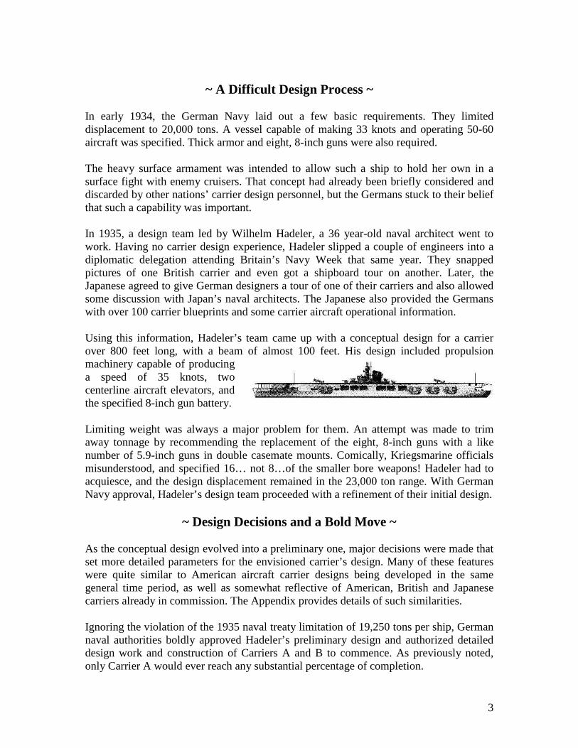
~ A Difficult Design Process ~ In early 1934, the German Navy laid out a few basic requirements. They limited displacement to 20,000 tons. A vessel capable of making 33 knots and operating 50-60 aircraft was specified. Thick armor and eight, 8-inch guns were also required. The heavy surface armament was intended to allow such a ship to hold her own in a surface fight with enemy cruisers. That concept had already been briefly considered and discarded by other nations’ carrier design personnel, but the Germans stuck to their belief that such a capability was important. In 1935, a design team led by Wilhelm Hadeler, a 36 year-old naval architect went to work. Having no carrier design experience, Hadeler slipped a couple of engineers into a diplomatic delegation attending Britain’s Navy Week that same year. They snapped pictures of one British carrier and even got a shipboard tour on another. Later, the Japanese agreed to give German designers a tour of one of their carriers and also allowed some discussion with Japan’s naval architects. The Japanese also provided the Germans with over 100 carrier blueprints and some carrier aircraft operational information. Using this information, Hadeler’s team came up with a conceptual design for a carrier over 800 feet long, with a beam of almost 100 feet. His design included propulsion machinery capable of producing a speed of 35 knots, two centerline aircraft elevators, and the specified 8-inch gun battery. Limiting weight was always a major problem for them. An attempt was made to trim away tonnage by recommending the replacement of the eight, 8-inch guns with a like number of 5.9-inch guns in double casemate mounts. Comically, Kriegsmarine officials misunderstood, and specified 16… not 8…of the smaller bore weapons! Hadeler had to acquiesce, and the design displacement remained in the 23,000 ton range. With German Navy approval, Hadeler’s design team proceeded with a refinement of their initial design.
~ Design Decisions and a Bold Move ~ As the conceptual design evolved into a preliminary one, major decisions were made that set more detailed parameters for the envisioned carrier’s design. Many of these features were quite similar to American aircraft carrier designs being developed in the same general time period, as well as somewhat reflective of American, British and Japanese carriers already in commission. The Appendix provides details of such similarities. Ignoring the violation of the 1935 naval treaty limitation of 19,250 tons per ship, German naval authorities boldly approved Hadeler’s preliminary design and authorized detailed design work and construction of Carriers A and B to commence. As previously noted, only Carrier A would ever reach any substantial percentage of completion.

4
~ Carrier A’s Construction Commences ~ A contract for Carrier A was awarded to Deutsche Werke Kiel AG on November 16, 1935. However, the yard was too busy building cruisers, destroyers, submarines and support vessels to immediately start work on the carrier. In addition, the detail drawings necessary for construction were not made available to the shipbuilders until months later. Carrier A’s keel was laid down December 28, 1936 on an inclined shipway; depicted on the right. Following the start of her construction in late 1936, a little less than 24 months elapsed before Carrier A was ready to be launched; a time period fairly typical for large warships built between the two world wars. Progress photos indicate shipbuilding practices utilized did not include much subassembly work, if there was any at all. Riveted construction dominated her hull assembly.
The image to the left is dated March, 1937, and includes a rerstrictive notice in the upper-left hand corner that the image is Geheim (Secret). This warning also appears on later progress photos of the ship, such as the next two, both dated September, 1937.
5
~ Launching Day ~
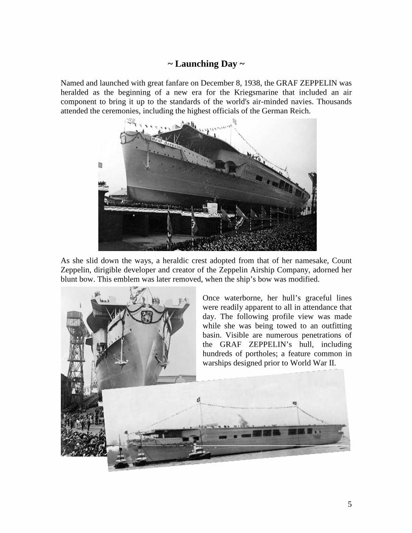
Named and launched with great fanfare on December 8, 1938, the GRAF ZEPPELIN was heralded as the beginning of a new era for the Kriegsmarine that included an air component to bring it up to the standards of the world's air-minded navies. Thousands attended the ceremonies, including the highest officials of the German Reich.
As she slid down the ways, a heraldic crest adopted from that of her namesake, Count Zeppelin, dirigible developer and creator of the Zeppelin Airship Company, adorned her blunt bow. This emblem was later removed, when the ship’s bow was modified.
Once waterborne, her hull’s graceful lines were readily apparent to all in attendance that day. The following profile view was made while she was being towed to an outfitting basin. Visible are numerous penetrations of the GRAF ZEPPELIN’s hull, including hundreds of portholes; a feature common in warships designed prior to World War II.

6
~ From Launch to Incompletion ~
This next image, dated September, 1939, shows the vessel’s stern, following completion of her flight deck, but before the island structure was fully erected. By early 1940, she was 85% complete, including a modification to her bow which increased her overall length slightly. Her island structure was essentially complete, at that time, as visible in the following photo.
It had been expected that the ship would be ready for sea trials in July 1940 and delivered in the winter of 1940-41. But the outbreak of World War II on September 1, 1939, caused work on the GRAF ZEPPELIN to slow, then stop almost completely as
resources and materials were diverted to U-Boat construction. All of the ship’s guns and her fire control system were diverted to other military uses. At the same time, efforts underway to modify land-based aircraft for carrier service were also stopped and the few prototype naval aircraft existing were transferred to the Luftwaffe.
On April 29, 1940, the head of the German Navy suggested that all work be terminated. He felt the ship, even if completed, would be worthless without guns, fire control and aircraft capable of carrier operations. The shipbuilders of Kiel turned their attentions to other work and the ship was moved from her birthplace to Gotenhafen, where it was thought she might be less likely to be subjected to Allied air attack.
Once moved and moored, the nearly complete GRAF ZEPPELIN began a short, undignified career as a floating warehouse. The ship was moved again in June of 1941, further away from possible retaliatory air raids by Russia that were expected to follow the German invasion of the Soviet Union that same year. When no air raids occurred, the ship was towed back to Gotenhafen in November of 1941.

7
~ Relocation, Relocation, Relocation! ~
As World War II progressed, the importance of aircraft carriers became more and more apparent. German naval leadership began to once again consider completing Graf Zeppelin. It was estimated that half of the ship’s machinery could be ready for operation by June 1943, with some changes to the incomplete catapult system being made at the same time. This indicated a possible delivery in the winter of 1943-44.
On May 15, 1942 the order was given to tow the carrier back to Kiel for completion. Modifications were made to the original design, based on input from the Luftwaffe and advances in naval technology, based on wartime experience. Plans were made to provide the vessel with a multitude of antiaircraft weapons, and anti-torpedo ‘bulges’ were designed for the midships portion of the vessel’s hull. All these changes increased her displacement and would have resulted in a reduction in maximum speed attainable.
On the night of August 27, 1942, while still at Gotenhaven, GRAF ZEPPELIN was attacked by British bombers. They dropped several bombs that had been modified by the addition of shaped warheads, intended to do maximum damage to an armored target. There is no known record of the ship suffering any damage from that night’s bomb strike.
GRAF ZEPPELIN was towed back to Kiel by three tugs in early December, 1942. Placed in a 40,000-ton floating dry dock, hull modifications were begun. Work also began to activate her inboard two shafts, which would have permitted a speed of 25 to 26 knots during sea trials that were scheduled to begin in the fall of 1943. Modifications were progressing well until January 30, 1943, when yet another stop work order was received, redirecting all naval construction work to concentrate on building U-Boats. By February 2nd, the majority of the shipbuilders had left the ship. Work was allowed to continue on some systems, which would have allowed GRAF ZEPPELIN to get steam up in one boiler and run the ship’s bilge pumps in the case of leaks. Her propellers were removed to facilitate easier towing and were stowed on the flight deck.
On April 21, 1942, tugs took the carrier under tow once more and moved her to Stettin. Camouflaged, she sat there for the rest of the war with only 18 inches of water
under her keel. Even the Allies ignored her, likely knowing there was no chance the ship could ever be completed, so she was spared from air attacks.

8
~ An Ending Shrouded in Mystery ~
In April of 1945, as the Red Army approached, her sea valves were opened and the ship settled on the bottom. A German Army demolition team was sent on board to rig explosives in the machinery areas. As the Russians entered Stettin on April 25, 1945, the vessel’s machinery was destroyed and portions of her bottom blow away.
According to the terms of the Allied Tripartite Commission, any damaged or scuttled German vessel was required to be destroyed or sunk in deep water by the end of 1946. Instead, Russian salvage experts patched up the carrier’s hull and re-floated her. The ship was loaded with war booty and then towed away in April of 1947. The last known images of her leaving Germany for the first…and the last…time are these two grainy photos.
For many years, no other information about the ship's ultimate fate was available. It seemed unlikely that she made it to a Russian port, since her arrival would likely have been noticed by Western intelligence services. Rumors of being sunk by hitting a mine were bandied about and generally accepted.
Decades later, two discoveries ended the mystery. In July of 2006, a Polish vessel performing underwater survey work found a large ship resting almost upright, 264 feet below the surface of the Baltic Sea. This sonar scan revealed the unmistakable image of a large aircraft carrier’s flight deck.
No aircraft carriers were listed as being sunk in the Baltic, so a closer examination of the hulk by maritime historians was conducted to verify that the GRAF ZEPPELIN had been found. Side-scan sonar and underwater cameras confirmed the wreck’s identity. This composite image was then created, utilizing hundreds of underwater photos.

9
~ The Rest of the Story ~
This find, at first, appeared to confirm the sunk-by-mine theory. Or, perhaps, as so often happens, that such a vunerable hulk had sprung leaks while being towed and had slipped beneath the waves. In either case, it was assumed that the Russian military would not have admitted to a failure to safely move the the carrier to Russia. But then, quite unexpectedly, Russian authorities permitted secret navy archives almost 60 years old to be opened, which shed an entirely new light on the mystery.
Those records indicate that in August of 1947 the uncompleted aircraft carrier was towed out into the Baltic and used for weapons testing. A number of large explosive charges were positioned on her flight and hangar decks, and detonated to simulate bomb hits. One such device was placed in her funnel, completely destroying it when set off.
Dive bombers also used her for target practice, scoring six hits. The effects of all these explosions on the helpless hulk were not enough to sink her, so two torpedoes were fired point-blank into her mid-section to finally finish her off. The purpose of this target practice was more than just an evaluation of Russian ordinance and routine training. The Soviets wanted to gain experience in sinking an aircraft carrier!
At that point in time, the Cold War was underway and the Russians were very aware of the number of American aircraft carriers in service in European waters and their potential to attack the Soviet Union, in the event of war. If the Cold War had ever escalated into World War II, the US Navy’s carriers would have been targets of strategic importance.
After being damaged by 24 bombs and other explosive devices, the GRAF ZEPPELIN refused to go down after two days of punishment. She had to be finished off by torpedoes fired at close range, as noted above. The Russian military surely knew that the post-World War II American super carriers, all designed and mostly constructed by Newport New Shipbuilding craftsmen, had far greater battle damage-resistance capabilities than the incomplete and unmanned German carrier.
In addition, they knew with grim certainty that American aviators and carrier crews would never sit idly if attacked. The likelihood that Russian aircraft could get close enough to drop multiple bombs on an America super carrier was very small. The possibility of Russian surface ships…or even submarines…penetrating an American carrier task force’s defenses was nearly impossible.
Who knows?…perhaps all this entered into the equation that prevented the Cold War from ever getting ‘hot’. If so, then Germany’s Almost Aircraft Carrier may have provided a vital, albeit never anticipated service, after all.

10
~ Postscript ~
I have long been aware that Germany attempted to build an aircraft carrier. I understood that the GRAF ZEPPELIN was never completed and assumed that was because of Allied bombing attacks. I further assumed that she had been sunk during World War II, or scrapped shortly after the war ended.
When her sunken hulk was discovered a few years ago, it got a lot of play in the media…and then the story faded. Then Russia’s involvement with the rest of her became known. When I recently stumbled across that information, I decided it was time to relate her entire story.
As I gathered information from a variety of published and Internet sources, I recalled that in the same time frame when the Germans were designing their aircraft carrier, the talented designers at Newport News Shipbuilding were busy doing the same thing. As I poured over the amazing amount of detailed information and fascinating photos available about the GRAF ZEPPELIN, I began making mental comparisons of her design with the design created at NNS in the 1930’s that resulted in the creation of the three carriers of the YORKTOWN-Class.
That’s when I decided to do something perhaps never done before; to create a semi-technical study of the similarities and differences between the GRAF ZEPPELIN design and that of the YORKTOWN-Class. The Appendix that follows is the result.
Most people who may see this article will probably be content to just read about Germany’s almost aircraft carrier. Accordingly, I recommend that the casual reader stop here…or maybe just skim the Appendix and look at some of the interesting illustrations.
But for those interested in design triva, I offer the Appendix. In particular, I have in mind the decades of NNS designers who have collectively contributed light-years of insightful effort to produce a series of highly successful aircraft carrier designs.
Bill Lee June 2010

11
~ APPENDIX ~
A COMPARISON OF AIRCRAFT CARRIER DESIGNS
THE GRAF ZEPPELIN
~ Vs. ~
THE YORKTOWN-Class

12
~ Introduction ~
Germany’s attempt to build aircraft carriers resulted in only one vessel, the GRAF ZEPPELIN, being launched. In spite of reaching a high percentage of completion, she never sailed under her own power and is little more than a footnote in history. In stark contrast, the three American carriers that constituted the YORKTOWN-Class made major contributions to victory in World War II. YORKTOWN (CV-5), ENTERPRISE (CV-6) and HORNET (CV-8) were products of the Newport News Shipbuilding & Dry Dock Company (NNS). That trio of vessels and the numerous NNS-created aircraft carriers that have followed constitute the bulk of America’s rich Naval Aviation history. The two carrier designs that are the subject of this comparison were developed in the same era. While the German and the American designs were developed completely separate from one another and in varying degrees of secrecy, they did have many common features; perhaps more than might have been expected. As these two flight deck plans indicate, the size and shape of their flight decks were very similar (GRAF ZEPPELIN shown above; YORKTOWN below). These and other similarities are explored in more detail in the following sections of this Appendix. There are also some startling differences to be found when contrasting these designs. Some of the details that are discussed in this comparison that were made by either the Germans or the Americans may appear quaint; perhaps even amusing. But, of course, evaluating 1930 technology with the benefit of 2010 knowledge is inappropriate. This comparison of design basics is just that. No judgments are made (well, not too many!). In each section, GRAF ZEPPELIN information is generally provided first, followed by comparable American data, with text colored navy blue for differentiation.
This Appendix contains some repetition of the ship’s history to allow the reader to avoid referring to previous pages. For those who have ever experienced the hard choices, the trade-offs and inevitable surprises inherent in ship design; this comparison should be of some academic interest. It may also rekindle memories of the ultimate satisfaction of a demanding and complex job well done.

13
~ Overview ~
The GRAF ZEPPELIN represented an unrealized desire on the part of Germany before the start of World War II to create a well-balanced oceangoing fleet, capable of projecting German naval power beyond the narrow confines of the Baltic and North Seas.
Having no experience building such ships, the Kriegsmarine had difficulty implementing advanced technologies such as aircraft catapults into the proposed design. German designers were able to study Japanese designs, but were constrained by the realities of creating a North Sea-capable carrier vs. a "Blue Water" design. Large bore guns of the size usually found on cruisers were specified to provide for commerce raiding and for defense against British warships. This was in contrast to American and Japanese designs, which were far more oriented toward a task-force style of defense, using supporting vessels to provide any needed surface firepower.
Design concepts for the German vessel were initiated in 1933. A construction contract was let in November 1935. The ship was launched December 8, 1938. After several years of sporadic work that included numerous design changes, all construction was suspended in early 1943 when she was 85% complete. After languishing for over two years, she was scuttled by the Germans in 1945. The Russians later raised and partially repaired her, and then towed her behind the Iron Curtain. Decades later, following an unexpected discovery of her sunken hulk in the Baltic Sea in 2006, GRAF ZEPPELIN’s ‘last mission’ was revealed.
Roughly in parallel with Germany’s carrier project, the United States initiated a similar-sized aircraft carrier design. In 1931, the US Navy started planning for the construction of aircraft carriers that would incorporate lessons learned from operating four earlier American carriers; the majority of which had been conversions from other types of naval vessels. Three vessels were built by Newport News Shipbuilding & Dry Dock Company to the new design: YORKTOWN (CV-5), ENTERPRISE (CV-6) and HORNET (CV-8).
14
The capacity of the Newport News shipyard allowed the construction of YORKTOWN and ENTERPRISE to proceed rapidly. Ordered in 1933, they were delivered in 1937 and 1938, respectively. YORKTOWN was lost at the Battle of Midway in 1942. ENTERPRISE survived the entire conflict and was heralded as the most decorated ship of World War II when she was decommissioned in 1947. She was subsequently scrapped in 1958 after a number of futile efforts to preserve her as a museum ship. HORNET, the third vessel of this class was ordered in 1939. Her construction was accelerated when America’s entry into World War II seemed inevitable. She was delivered in 1941. The following April, HORNET served as the base for Doolittle’s raid on Tokyo. Two months later, her aircraft were instrumental in the sinking of four Japanese carriers off Midway. Her career ended in late 1942 when she was lost in action.
~ A Comparison of Basic Ship Characteristics ~
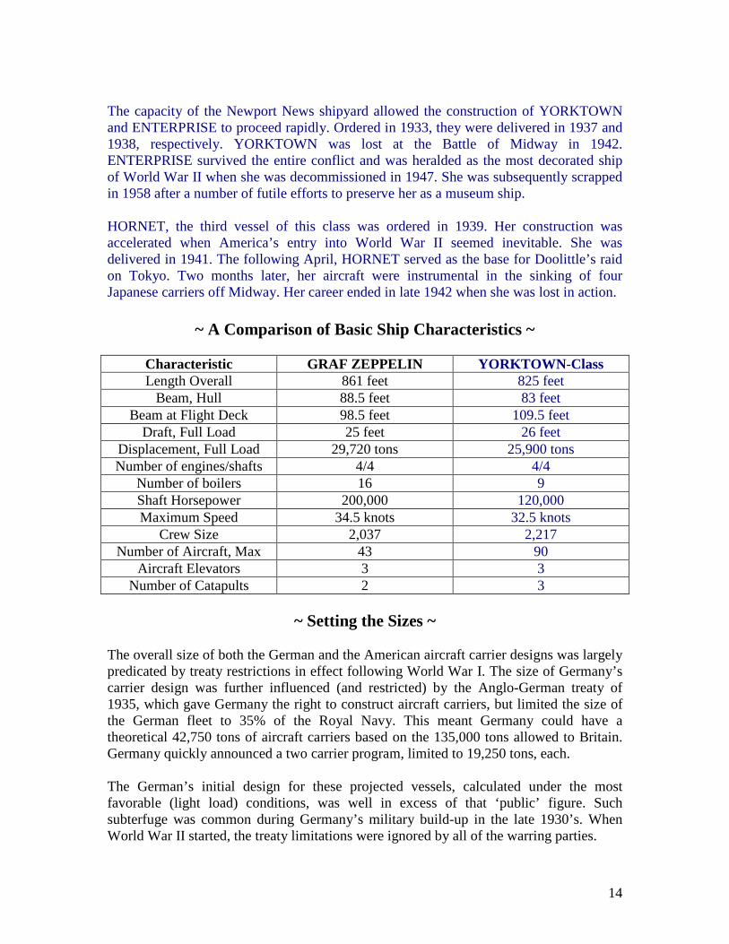
Characteristic GRAF ZEPPELIN YORKTOWN-Class Length Overall 861 feet 825 feet
Beam, Hull 88.5 feet 83 feet Beam at Flight Deck 98.5 feet 109.5 feet
Draft, Full Load 25 feet 26 feet Displacement, Full Load 29,720 tons 25,900 tons Number of engines/shafts 4/4 4/4
Number of boilers 16 9 Shaft Horsepower 200,000 120,000 Maximum Speed 34.5 knots 32.5 knots
Crew Size 2,037 2,217 Number of Aircraft, Max 43 90
Aircraft Elevators 3 3 Number of Catapults 2 3
~ Setting the Sizes ~
The overall size of both the German and the American aircraft carrier designs was largely predicated by treaty restrictions in effect following World War I. The size of Germany’s carrier design was further influenced (and restricted) by the Anglo-German treaty of 1935, which gave Germany the right to construct aircraft carriers, but limited the size of the German fleet to 35% of the Royal Navy. This meant Germany could have a theoretical 42,750 tons of aircraft carriers based on the 135,000 tons allowed to Britain. Germany quickly announced a two carrier program, limited to 19,250 tons, each. The German’s initial design for these projected vessels, calculated under the most favorable (light load) conditions, was well in excess of that ‘public’ figure. Such subterfuge was common during Germany’s military build-up in the late 1930’s. When World War II started, the treaty limitations were ignored by all of the warring parties.

15
The post-World War I naval treaty gave America a much larger aircraft carrier tonnage allotment. The initial Yorktown-Class design, for two sister ships, was intended to ‘build up’ the Navy’s force of aircraft carriers to full treaty limitations. At that time, the Navy had four carriers of varying displacement and differing designs in commission. The first of these was a converted coal collier of very modest size. The next two carriers were much larger; conversions that utilized the hulls and machinery of battle cruisers under construction at the end of World War I that otherwise would have been scrapped. The fourth of America’s aircraft carriers was the first to designed and built ‘from the keel up’. This relatively small fleet aircraft carrier, RANGER (CV-4), was a NNS product. The experience of creating and operating that vessel, plus feedback from the fleet from the other carriers, provided the basis for the designers at Newport News to develop the Yorktown-Class, which was 36% larger than RANGER. The HORNET’s displacement was slightly larger than her two sister ships, but dimensionally all three were identical. The central philosophy of the YORKTOWN-Class design development was to provide the means to support and operate the maximum number of aircraft, without extensive means of self-protection, other than their aircraft. In addition, ‘room for growth’ was a prime consideration. American naval aircraft under design in the 1930’s was considerably larger and heavier than post-World War I aircraft that had been mostly bi-planes and not specifically designed for operation at sea. Larger aircraft elevators, with greater lifting capacities were specified, along with catapults capable of launching heavier planes.
~ German Design Concepts Employed and Adjusted ~ In 1934, German naval authorities specified the following requirements for an aircraft carrier:
• Displacement of approximately 20,000 tons • Speed of 33 knots • Compliment of 50-60 aircraft • Armor protection equal to a contemporary light cruiser • Anti-surface armament of eight, 8-inch guns
The high speed requirement was to allow the carrier to escape enemy capital ships. The heavy surface armament was to allow the ship to hold her own in a surface fight. The German’s insistence on a surface combat capability was likely due to a lack of enough surface combatants to form carrier task forces. Due to the limitations of aircraft available in the 1930’s; they envisioned that carriers would have to operate fairly close to enemy fleets, and it was deemed likely that carriers would encounter enemy surface units and have to fight, rather than flee. The concept of conducting sustained carrier operations in combat apparently did not cross their mind. Neither did the strategy to surround aircraft carriers with a protective screen of ships as was later demonstrated so successfully in the Pacific.

16
In 1935, a conceptual design was developed by the Germans for a full deck carrier. This design came in at 23,000 tons, including a very high freeboard for operations in the Atlantic and the North Sea, a propulsion plant capable of 35-knot speed, two centerline aircraft elevators, and the specified 8-inch gun battery.
Following approval of this concept, a preliminary design was created. Weight was always a major problem. Various solutions to reduce weight were employed, but the inevitable additions that come with advanced ship design added weight. When the preliminary design was presented to Kriegsmarine officials, the ship had grown in displacement to well over 23,000 tons; almost 20% over the limit imposed by treaty. Ignoring this violation, German naval authorities approved the design and detail design work was started. By late 1936, sufficient production drawings were available to allow construction of the first German carrier to commence.
~ Building on American Carrier Know-How ~
In sharp contrast to the inexperienced carrier design team’s approach employed in Germany in the 1930’s, the combination of America’s prior carrier construction work and the US Navy’s operational experience contributed significantly to the thoughtful and well-executed design of the YORKTOWN-Class. Operational experience with CV-2 and CV-3, the two aircraft carriers that had been converted from battle cruisers, resulted in the Navy specifying a minimum displacement for future carriers of 20,000 tons. That figure was calculated to be sufficient to permit the new carrier design to accommodate up to 90 aircraft. This decision was verified when the 14,000 ton RANGER went into service. She could only carry half that number. CV-2 and CV-3 had been fitted at the flight deck level, with eight, 8-inch guns mounted in four twin turrets; somewhat mirroring (but preceding) the German concept of providing anti-ship capability. But the US Navy soon discovered that these weapons were of little use, and took up valuable flight deck space. Consequently, the YORKTOWN-Class had eight, 5-inch dual-purpose weapons arranged in pairs on sponsons located to either side of the hull structure, fore and aft, and just below the flight deck level. Desired improvements in survivability resulted in specifying ‘defense in depth’ side protection tanks in way of vital spaces. Machinery spaces were sub-divided to provide added protection. Nine boilers installed in each ship were located in individual watertight compartments that were located forward of two engine rooms. Electrical generators were located aft of the engine rooms in their own dedicated watertight compartments.

17
Prior operational experience indicated the need for three aircraft elevators (rather than just two, as provided for CV-2 and CV-3). More weapons-handling elevators and greater fire fighting capability than had previously been fitted in any American aircraft carrier was also specified. Numerous similar and differing design details pertaining to the German and American designs are included in the next two sections of this Appendix. The basic design criteria for the YORKTOWN-Class carriers was set by the Navy, giving NNS designers complete freedom to develop both the contract design drawings and the detail plans necessary to construct the three carriers. This set a precedent for every class of United States carriers to follow; including the current design effort for CVN-78. The massive construction capability of the Newport News yard allowed for a rapid construction schedule for the first two carriers of the YORKTOWN-Class. YORKTOWN took 40 months, from keel to delivery; ENTERPRISE a little longer, due to equipment delivery delays. HORNET required only 26 months to go from keel to delivery.
~ The Similarities ~
As indicated in the table on the Page 14, the dimensional and displacement numbers as well as other pertinent data for the Yorktown-Class of carriers and the GRAF ZEPPELIN were quite similar. But there were many other similarities in design philosophy, which is somewhat remarkable, given the vastly different baseline of carrier design expertise in the two countries and the lack of any known exchange of information and ideas. Of course, the Germans probably had access to American and British naval publications. Before the start of World War II, such materials often contained a wealth of detailed information for copy-cat designers. In addition, uncensored photos of various carriers under construction or in commission would have helped the make up for the lack of hands-on experience by the German aircraft carrier design team. The following list identifies the most significant of pre-World War II carrier design concepts common to both the Germans and the Americans:
• Extremely large length-to-beam ratios • Highly sub-compartmented throughout • Several layers of side protection tankage in way of vital spaces • Four propellers, four steam turbines and multiple oil-fired boilers • Large island structures, located on the starboard side, with integral uptakes • Uptakes integral with island structures • Wood sheathed, ‘straight-through’ flight decks with little overhang, either side • Multiple arresting gear assemblies and mechanical aircraft catapults • Three aircraft elevators all located near or on ships’ centerlines • Gallery Decks that were non-continuous for the full lengths of the ships • Multiple anti-aircraft installations of varying calibers

18
~ The Differences ~
What follows is sub-divided into logical subjects, with more emphasis placed on the German design details heretofore relatively unknown than the much better known comparable items of American creation. Hull : GRAF ZEPPELIN’s hull was divided into 19 watertight compartments, the standard division for all capital ships in the Kriegsmarine. Her original length-to-beam ratio was a very slender 9.26:1. It was later reduced slightly by the addition of structural bulges on either side of her midbody.
Her hull side protection system was similar to German standard design for capital ships of that era. Plating thicknesses shown in this cross-section vary from 80 mm (3.1 inches) in way of her vital spaces to just 20 mm (0.79 inches) on her flight deck. After launch, modifications to provide additional anitaircraft weapons, larger control spaces for conducting flight operations, and heavier masts for supporting large and heavy radar antennae increased weight above the waterline. The solution for the resultant decrease in stability was addition of the bulges mentioned above, as shown here. The bulges also provided additional anti-torpedo protection and increased her calculated operating range by creating storage space for 1,500 more tons of fuel oil.
The hulls of the YORKTOWN-Class carriers were fitted with a belt of armor four inches thick, extending down both sides in way of their machinery spaces and other vital spaces. These carriers also had thinner armor plating on their hangar decks, but none on the flight decks. This latter lack of armor was a concession to weight limits imposed by treaty and also provided greater stability. The American design also featured the ‘defence-in-depth’ concept developed for battleships during World War I. Three or four layers of highly-compartmented, vertical deep tanks were provided on both sides of their propulsion spaces, ammunition storage compartments and aviation fuel tanks; quite similar to modern-day designs. This concept not only provided a reasonable degree of protection, but also created the capability to counterflood selected tanks in order to help keep a damaged carrier on an even keel; vital to continued aircraft operations.
Unlike American carriers of that era, the German carrier’s flight deck was designed and constructed as her uppermost strength deck. Her steel flight deck plates were sheathed with wood. This characteristic was likely ‘borrowed’ from British carrier designs. Curiously, the Germans did not adopt the British enclosed bow design.

19
The YORKTOWN-Class ships’ flight decks consisted primarily of thick Douglas fir wooden planks; laid over a combination of partial gallery deck spaces and a skeleton steel framework in areas where the gallery deck was not continuous. This concept reduced topside weight, but did not fare well in combat, when bombs and suicide planes penetrated the flight decks of unfortunate carriers and caused extended damage in their hangar bays and other spaces below flight decks. The next generation carrier design (ESSEX-Class) retained the light steel/wood sheathed flight deck combination. Beginning with the follow-on MIDWAY-Class, the present-day all-steel, armored deck concept was introduced. That latter class of carriers was also the first to feature gallery decks extending the length of the flight decks immediately above. Both country’s designs featured ‘open’ foredecks at the hangar deck level. The flight decks did not reach out over the ships’ prows. But in the case of the German vessel, the bow extended much further forward, under the flight deck. The GRAF ZEPPELIN’s original straight-stemmed and decorated bow (see Page 1 photo) was modified in 1940 by the addition of a sharply angled "Atlantic Prow", intended to improve overall seakeeping. This change added seventeen feet to her original length. After World War II the open foredeck concept was abandoned by American aircraft carrier designers in favor of the now-universal enclosed bow seen on all modern carriers. This change was due in part to damage suffered in storms. More than one carrier, such as ENTERPRISE (depicted here in 1944) weathered typhoons in the Pacific, but had their flight decks badly damaged when the carriers had to plow directly into towering seas to survive. Machinery: GRAF ZEPPELIN's power plant consisted of 16 high-pressure boilers, similar to those used in German heavy cruisers. Her four sets of geared turbines, connected to four shafts, were initially calculated to produce 200,000 SHP and capable of providing speeds up to 35 knots (40 mph). Other German major warships had three shafts, producing SHP in the range of 150,000. Later changes in hull configuration and weight additions, previously discussed, made her too heavy to achieve such a high speed.
20
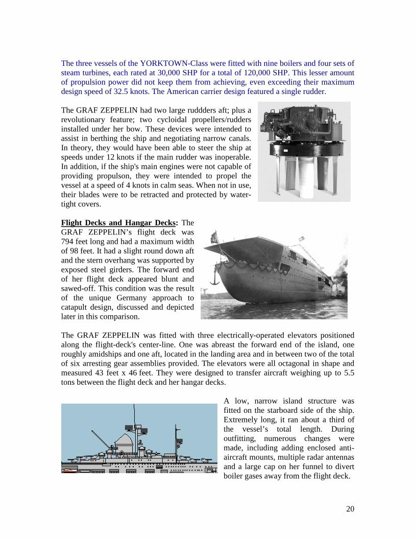
The three vessels of the YORKTOWN-Class were fitted with nine boilers and four sets of steam turbines, each rated at 30,000 SHP for a total of 120,000 SHP. This lesser amount of propulsion power did not keep them from achieving, even exceeding their maximum design speed of 32.5 knots. The American carrier design featured a single rudder. The GRAF ZEPPELIN had two large ruddders aft; plus a revolutionary feature; two cycloidal propellers/rudders installed under her bow. These devices were intended to assist in berthing the ship and negotiating narrow canals. In theory, they would have been able to steer the ship at speeds under 12 knots if the main rudder was inoperable. In addition, if the ship's main engines were not capable of providing propulson, they were intended to propel the vessel at a speed of 4 knots in calm seas. When not in use, their blades were to be retracted and protected by water-tight covers. Flight Decks and Hangar Decks: The GRAF ZEPPELIN’s flight deck was 794 feet long and had a maximum width of 98 feet. It had a slight round down aft and the stern overhang was supported by exposed steel girders. The forward end of her flight deck appeared blunt and sawed-off. This condition was the result of the unique Germany approach to catapult design, discussed and depicted later in this comparison. The GRAF ZEPPELIN was fitted with three electrically-operated elevators positioned along the flight-deck's center-line. One was abreast the forward end of the island, one roughly amidships and one aft, located in the landing area and in between two of the total of six arresting gear assemblies provided. The elevators were all octagonal in shape and measured 43 feet x 46 feet. They were designed to transfer aircraft weighing up to 5.5 tons between the flight deck and her hangar decks.
A low, narrow island structure was fitted on the starboard side of the ship. Extremely long, it ran about a third of the vessel’s total length. During outfitting, numerous changes were made, including adding enclosed anti-aircraft mounts, multiple radar antennas and a large cap on her funnel to divert boiler gases away from the flight deck.
21
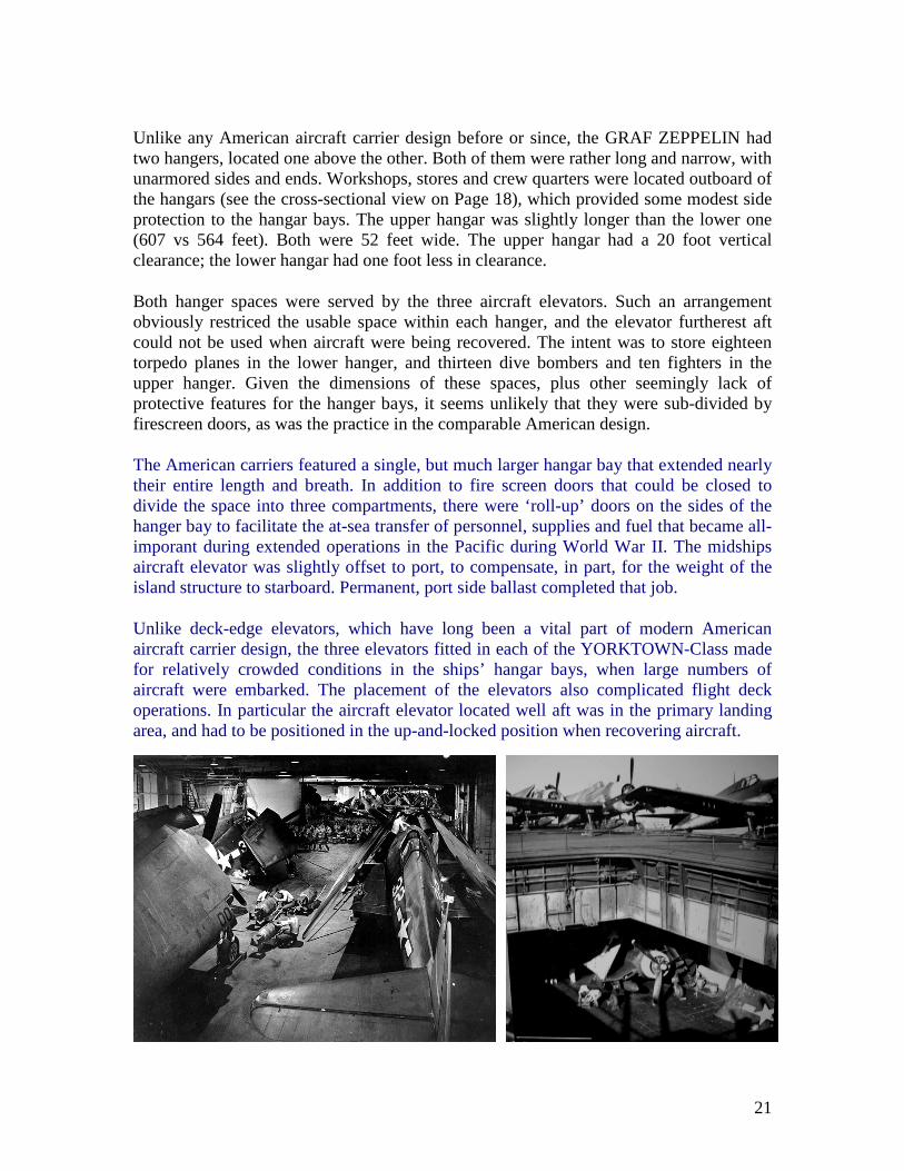
Unlike any American aircraft carrier design before or since, the GRAF ZEPPELIN had two hangers, located one above the other. Both of them were rather long and narrow, with unarmored sides and ends. Workshops, stores and crew quarters were located outboard of the hangars (see the cross-sectional view on Page 18), which provided some modest side protection to the hangar bays. The upper hangar was slightly longer than the lower one (607 vs 564 feet). Both were 52 feet wide. The upper hangar had a 20 foot vertical clearance; the lower hangar had one foot less in clearance.
Both hanger spaces were served by the three aircraft elevators. Such an arrangement obviously restriced the usable space within each hanger, and the elevator furtherest aft could not be used when aircraft were being recovered. The intent was to store eighteen torpedo planes in the lower hanger, and thirteen dive bombers and ten fighters in the upper hanger. Given the dimensions of these spaces, plus other seemingly lack of protective features for the hanger bays, it seems unlikely that they were sub-divided by firescreen doors, as was the practice in the comparable American design.
The American carriers featured a single, but much larger hangar bay that extended nearly their entire length and breath. In addition to fire screen doors that could be closed to divide the space into three compartments, there were ‘roll-up’ doors on the sides of the hanger bay to facilitate the at-sea transfer of personnel, supplies and fuel that became all-imporant during extended operations in the Pacific during World War II. The midships aircraft elevator was slightly offset to port, to compensate, in part, for the weight of the island structure to starboard. Permanent, port side ballast completed that job.
Unlike deck-edge elevators, which have long been a vital part of modern American aircraft carrier design, the three elevators fitted in each of the YORKTOWN-Class made for relatively crowded conditions in the ships’ hangar bays, when large numbers of aircraft were embarked. The placement of the elevators also complicated flight deck operations. In particular the aircraft elevator located well aft was in the primary landing area, and had to be positioned in the up-and-locked position when recovering aircraft.

22
The YORKTOWN-Class design for flight and hanger decks, while similar in general external appearance, and number and general positioning of aircraft elevators to that of the Germans; featured some interesting differences. The American carriers’ flight decks were fitted with arresting gear both aft and forward (seven assemblies in each location). In addition to the familiar landing officers’ platform on the port-stern corner of their flight decks, a duplicate platform was provided on the starboard-bow corner.
The US Navy’s reasoning was that if battle damage or a plane crash made a carrier’s normal landing area inoperable, the affected carrier should be able to steam astern and recover aircraft over the bow. Navy specifications required that class of carrier be capable of steaming astern at 20 knots. The sterns of the three carriers of the YORKTOWN-Class were streamlined to permit such an evolution to be conducted. As shown here, that requirement was demonstrated during YORKTOWN’s trials. It is not known if this mode of aircraft recovery was ever attempted at sea.
The most interesting feature created by either county involved aircraft catapult designs. The German system was so complicated and different from what American ship designers visualize when ‘aircraft catapults’ are mentioned, that it merits description.
Catapults: Two compressed air-driven catapults were installed at the forward end of the German carrier’s flight deck for power-assisted launches. They were 75 feet long and designed to launch aircraft weighing 11,000 pounds. Each catapult included a narrow, deep ‘trough’ in which a collapsible launch trolley was to be propelled forward.
As each plane lifted off, its launch trolley would have been caught in a metal "basket". Lowered to the open forecastle via a ramp, it would then have been rolled back on rails to the upper hangar for re-use. There, an aircraft would have been lifted by crane onto the trolley and then lifted to the flight deck by the forward elevator. A set of rails embedded in the flight deck would allow for the aircraft to be trundled forward for launch.
23
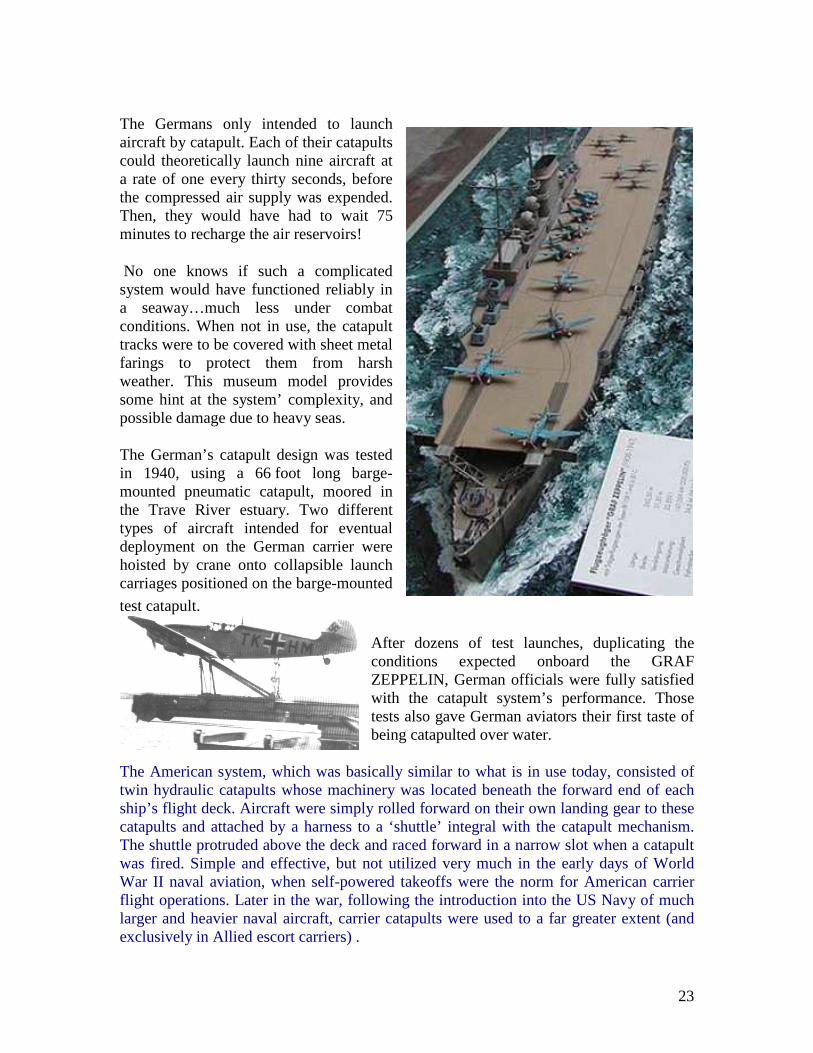
The Germans only intended to launch aircraft by catapult. Each of their catapults could theoretically launch nine aircraft at a rate of one every thirty seconds, before the compressed air supply was expended. Then, they would have had to wait 75 minutes to recharge the air reservoirs!
No one knows if such a complicated system would have functioned reliably in a seaway…much less under combat conditions. When not in use, the catapult tracks were to be covered with sheet metal farings to protect them from harsh weather. This museum model provides some hint at the system’ complexity, and possible damage due to heavy seas.
The German’s catapult design was tested in 1940, using a 66 foot long barge-mounted pneumatic catapult, moored in the Trave River estuary. Two different types of aircraft intended for eventual deployment on the German carrier were hoisted by crane onto collapsible launch carriages positioned on the barge-mounted
test catapult.
After dozens of test launches, duplicating the conditions expected onboard the GRAF ZEPPELIN, German officials were fully satisfied with the catapult system’s performance. Those tests also gave German aviators their first taste of being catapulted over water.
The American system, which was basically similar to what is in use today, consisted of twin hydraulic catapults whose machinery was located beneath the forward end of each ship’s flight deck. Aircraft were simply rolled forward on their own landing gear to these catapults and attached by a harness to a ‘shuttle’ integral with the catapult mechanism. The shuttle protruded above the deck and raced forward in a narrow slot when a catapult was fired. Simple and effective, but not utilized very much in the early days of World War II naval aviation, when self-powered takeoffs were the norm for American carrier flight operations. Later in the war, following the introduction into the US Navy of much larger and heavier naval aircraft, carrier catapults were used to a far greater extent (and exclusively in Allied escort carriers) .
24
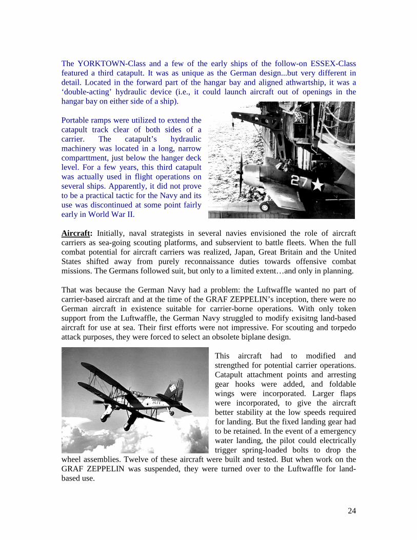
The YORKTOWN-Class and a few of the early ships of the follow-on ESSEX-Class featured a third catapult. It was as unique as the German design...but very different in detail. Located in the forward part of the hangar bay and aligned athwartship, it was a ‘double-acting’ hydraulic device (i.e., it could launch aircraft out of openings in the hangar bay on either side of a ship).
Portable ramps were utilized to extend the catapult track clear of both sides of a carrier. The catapult’s hydraulic machinery was located in a long, narrow comparttment, just below the hanger deck level. For a few years, this third catapult was actually used in flight operations on several ships. Apparently, it did not prove to be a practical tactic for the Navy and its use was discontinued at some point fairly early in World War II.
Aircraft : Initially, naval strategists in several navies envisioned the role of aircraft carriers as sea-going scouting platforms, and subservient to battle fleets. When the full combat potential for aircraft carriers was realized, Japan, Great Britain and the United States shifted away from purely reconnaissance duties towards offensive combat missions. The Germans followed suit, but only to a limited extent…and only in planning.
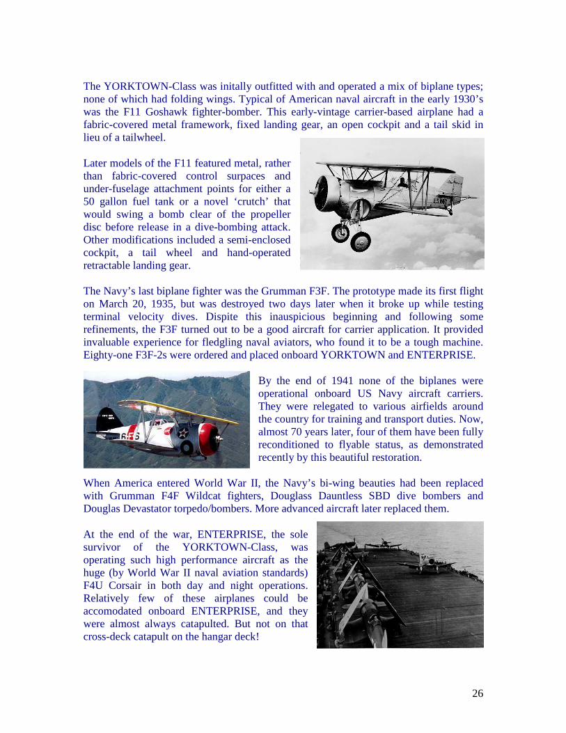
That was because the German Navy had a problem: the Luftwaffle wanted no part of carrier-based aircraft and at the time of the GRAF ZEPPELIN’s inception, there were no German aircraft in existence suitable for carrier-borne operations. With only token support from the Luftwaffle, the German Navy struggled to modify exisitng land-based aircraft for use at sea. Their first efforts were not impressive. For scouting and torpedo attack purposes, they were forced to select an obsolete biplane design.
This aircraft had to modified and strengthed for potential carrier operations. Catapult attachment points and arresting gear hooks were added, and foldable wings were incorporated. Larger flaps were incorporated, to give the aircraft better stability at the low speeds required for landing. But the fixed landing gear had to be retained. In the event of a emergency water landing, the pilot could electrically trigger spring-loaded bolts to drop the
wheel assemblies. Twelve of these aircraft were built and tested. But when work on the GRAF ZEPPELIN was suspended, they were turned over to the Luftwaffle for land-based use.

25
The Kraigsmarine had a little better luck with fighters and dive bombers. A carrier-borne version of the famous Messerschmitt Bf 109 was created and tested, including full-scale wind tunnel testing. Simulated catapult launches from a barge for this aircraft were also conducted (see second photo on Page 23).
Designated Bf 109T (the "T" stood for Träger, or Carrier), this version of the Me Bf 109 had a wing span of 36 feet and thus did not require folding wings since the German carrier design featured aircraft elevators 46 feet wide. The Bf 109T’s wings were fitted with retractable slats to facilitate the low-speed stability necessary for carrier operations.
A total of 155 of these machines were ordered, a number later reduced to 70. But only seven were completed as Bf 109T’s. The rest were modified on the production line to the original land-based design. These aircraft, including the seven Bf 109T’s, eventually were incorporated into Luftwaffle squadrons as interest in completing the GRAF ZEPPELIN waned.
In May of 1942, when work was ordered resumed on the carrier, the Bf 109T fighter was considered obsolete. Design work was initiated on an improved fighter for use on the carrier. Designated Me 155, detailed plans were completed by September of 1942. Before the Me 155 could be placed in production, all interest in completing Germany’s aircraft carrier had disappeared altogether and the Me 155 was never produced.
For a dive bomber, the combat-proven Junkers Ju 87B Stuka was chosen. Work on converting the Ju 87 into the carrier version (Ju 87C) began in late 1938. The Ju 87Cs had folding wings, reducing carrier stowage width to just 16 feet. In addition to incorporating catapult attachment points and an arrester hook, the airframe was strengthened to better withstand the stresses of carrier landings.
Similar to the torpedo plane design, this aircraft’s fixed landing gear was capable of being jettisoned in the event it had to ditch in the sea. Ten of these modified aircraft were built and tested. Those tests not only included catapult launches, but also simulated deck landings on a airfield that was marked with an outline of the German carrier’s flight deck and fitted with arresting gear. 170 Ju 87C’s were ordered, but only a few were ever completed. The handful of existing aircraft were eventually converted back into Ju 87B’s.
26
The YORKTOWN-Class was initally outfitted with and operated a mix of biplane types; none of which had folding wings. Typical of American naval aircraft in the early 1930’s was the F11 Goshawk fighter-bomber. This early-vintage carrier-based airplane had a fabric-covered metal framework, fixed landing gear, an open cockpit and a tail skid in lieu of a tailwheel.
Later models of the F11 featured metal, rather than fabric-covered control surpaces and under-fuselage attachment points for either a 50 gallon fuel tank or a novel ‘crutch’ that would swing a bomb clear of the propeller disc before release in a dive-bombing attack. Other modifications included a semi-enclosed cockpit, a tail wheel and hand-operated retractable landing gear.
The Navy’s last biplane fighter was the Grumman F3F. The prototype made its first flight on March 20, 1935, but was destroyed two days later when it broke up while testing terminal velocity dives. Dispite this inauspicious beginning and following some refinements, the F3F turned out to be a good aircraft for carrier application. It provided invaluable experience for fledgling naval aviators, who found it to be a tough machine. Eighty-one F3F-2s were ordered and placed onboard YORKTOWN and ENTERPRISE.
By the end of 1941 none of the biplanes were operational onboard US Navy aircraft carriers. They were relegated to various airfields around the country for training and transport duties. Now, almost 70 years later, four of them have been fully reconditioned to flyable status, as demonstrated recently by this beautiful restoration.
When America entered World War II, the Navy’s bi-wing beauties had been replaced with Grumman F4F Wildcat fighters, Douglass Dauntless SBD dive bombers and Douglas Devastator torpedo/bombers. More advanced aircraft later replaced them.
At the end of the war, ENTERPRISE, the sole survivor of the YORKTOWN-Class, was operating such high performance aircraft as the huge (by World War II naval aviation standards) F4U Corsair in both day and night operations. Relatively few of these airplanes could be accomodated onboard ENTERPRISE, and they were almost always catapulted. But not on that cross-deck catapult on the hangar deck!

27
Weaponary: GRAF ZEPPELIN was armed with separate high and low angle guns for anti-ship and antiaircraft (AA) defense at a time when most other major navies were switching to dual-purpose AA weapons and relying on escort ships to protect their carriers from surface threats. Her primary anti-shipping armament was somewhat of a throw-back to the notion that battle fleets would always slug it out, surface vessel to surface vessel. Accordingly, she was fitted with sixteen 5.9-inch guns paired in eight armored casemates, positioned bow and stern on either side.
This pre-launch photo clearly shows the position of the two casemates on the forward-port side of the vessel. Apparently, little or no consideration was given to the possibility that the weapons that were planned to be installed in these openings might become inoperatable or even damaged in heavy seas. Especially vunerable would have been the casemates at the forward end of the vessel.
The photo also illustrates the pre-World War II practice of all navies to provide portholes for crew comfort in what were totally non-air conditioned ships. This same, now long discarded practice that would shock today’s damage control experts was duplicated in the YORKTOWN-Class, as evidenced by numerous pictures of those ships.
Primary AA protection for Germany’s carrier was to have been provided by twelve 4.1-inch guns, paired in six turrets positioned three forward and three aft of the carrier’s island (see island profile drawing on the bottom of Page 20). Potential blast damage to planes sited midships on the flight deck when such weaponary had to be fired at low angles to port was a resultant, unavoidable risk and would have limited any flight activity during such an engagement.
GRAF ZEPPELIN’S secondary AA defenses was to have consisted of eleven twin 1.5-inch gun mounts, located on sparce sponsons along the flight deck edges; four on the starboard side, six to port and one on the ship's forecastle. In addition, seven 20-mm machine guns were to be installed on single-mount platforms on either side of the carrier; four to port and three to starboard. It is doubful they were ever installed.
The YORKTOWN-Class was initially configured to have ten, 5-inch, dual-purpose open mounts. One was to be located on the bow and one on the stern. The rest paired on four sponsons located somewhat below and at the ‘corners’ of the flight deck.
Each ship was also initially fitted with with four quadruple 1.1-inch antiaircraft guns, plus twenty-four .50-caliber machine guns. These weapons were placed in gun tubs located all along both sides of the vessels’ flight decks, as well as high up on the island structure.
28
Following refits in early 1942, additional antiaircraft guns were added to each ship. Typically, these consisted of thirty 20-mm rapid fire weapons. Other advancements included some of the first radar sets to be installed in American naval vessels.
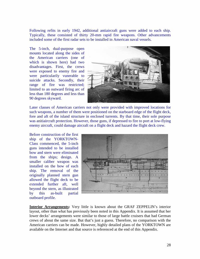
The 5-inch, dual-purpose open mounts located along the sides of the American carriers (one of which is shown here) had two disadvantages. First, the crews were exposed to enemy fire and were particularily vunerable to suicide attacks. Secondly, their range of fire was restricted; limited to an outward firing arc of less than 180 degrees and less than 90 degrees skyward.
Later classes of American carriers not only were provided with improved locations for such weapons, a number of them were positioned on the starboard edge of the flight deck, fore and aft of the island structure in enclosed turrents. By that time, their sole purpose was anitiaircraft protection. However, those guns, if depressed to fire to port at low-flying enemy aircraft, could damage aircraft on a flight deck and hazard the flight deck crew.
Before construction of the first ship of the YORKTOWN-Class commenced, the 5-inch guns intended to be installed bow and stern were eliminated from the ships; design. A smaller caliber weapon was installed on the bow of each ship. The removal of the originally planned stern gun allowed the flight deck to be extended further aft, well beyond the stern, as illustrated by this as-built partial outboard profile.
Interior Arrangements : Very little is known about the GRAF ZEPPELIN’s interior layout, other than what has previously been noted in this Appendix. It is assumed that her lower decks’ arrangements were similar to those of large battle cruisers that had German crews of about the same size. But that’s just a guess. Therefore, no comparison with the American carriers can be made. However, highly detailed plans of the YORKTOWN are available on the Internet and that source is referenced at the end of this Appendix.

29
~ Summary ~
No one knows how the GRAF ZEPPELIN might have performed, had she been completed. On paper, her design does not compare particularly well with contemporary carriers constructed by other nations that have proven records of successes. For a vessel of her size, she was designed to carry a surprisingly small number of aircraft, and her ability to rapidly launch them under battle conditions is questionable, at best. Her heavy caliber guns, intended for dealing with surface ship attacks would have virtually useless in combat. By the time she could have gone to sea, the Allies would have pounced on her from above, in lieu of engaging on the surface. That tactic sunk several German capital ships much more heavily armored than the GRAF ZEPPELIN. Conversely, there is no question that the three ships of the YORKTOWN-Class were well designed. After all, they acquitted themselves well in combat. The US Navy’s strategy to place them in the middle of formations, ringed by powerful battleships, cruisers and destroyers negated any need for the carriers to be able to fend off surface attacks. Not only were they collectively instrumental in turning the tide of war in the Pacific at the Battle of Midway, but lessons learned in their wartime application significantly influenced the even more successful ESSEX-Class of aircraft carriers. Their fundamental features were repeated in several later designs and can even be found in the 21st century design for a new class of super carriers. That next generation of American aircraft carriers will also include a host of improvements over the present-day nuclear-powered carriers; things never dreamed of by the designers of Newport News in the 1930’s.
~ Epilogue: The Last Similarity ~
In 1998, an expedition led by famed undersea explorer Robert Ballard found the remains of the USS YORKTOWN (CV-5) three miles beneath the surface of the Pacific Ocean. Much like the GRAF ZEPPELIN, she came to rest virtually upright. Her sturdy hull survived the plunge to that great depth, and even after resting there for over 55 years, many of the ship’s details are still recognizable. Her ghostly, but remarkably well-preserved remains were photographed in what Ballard described as: “…the most sterile water environment I've ever seen. You could see all the way across the flight deck. There was absolutely no biological growth on the YORKTOWN”.

30
~ References ~
There are dozens of Internet postings available, plus a few books about these aircraft carriers. Given current wide-spread use of the Internet, the following ‘same’ links precede images of individual ship books. All of these books are for sale on the Internet.
GRAF ZEPPELIN
• http://en.wikipedia.org/wiki/Graf_Zeppelin_class_aircraft_carrier • http://www.bobhenneman.info/grafzeppelin.htm • http://www.damninteresting.com/the-only-nazi-aircraft-carrier • http://www.spiegel.de/international/0,1518,428857,00.html • http://www.youtube.com/watch?v=kRpxNu1SqFk • http://www.avalanchepress.com/GrafZeppelin.php
YORKTOWN-Class
• http://www.hnsa.org/doc/plans/cv5.pdf • http://www.historycentral.com/Navy/Cv5Yorktown.html • http://en.wikipedia.org/wiki/USS_Yorktown_(CV-5) • http://www.history.navy.mil/photos/sh-usn/usnsh-xz/cv5.htm • http://en.wikipedia.org/wiki/USS_Enterprise_(CV-6) • http://www.history.navy.mil/photos/sh-usn/usnsh-e/cv6.htm • http://en.wikipedia.org/wiki/USS_Hornet_(CV-8) • http://www.navsource.org/archives/02/08.htm


![Led Zeppelin - Led Zeppelin II [Songbook]](https://static.fdocuments.net/doc/165x107/547a8890b37959892b8b4a0b/led-zeppelin-led-zeppelin-ii-songbook.jpg)
