
Gogo 2Ku Whitepaper - ThinKom€¦ · Bruce R. Elbert Application Technology Strategy, ... Gogo has...
23
Aeronautical Broadband for Commercial Aviation: Evaluating the 2Ku Solution Bruce R. Elbert Application Technology Strategy, L.L.C.
Transcript of Gogo 2Ku Whitepaper - ThinKom€¦ · Bruce R. Elbert Application Technology Strategy, ... Gogo has...
1
Aeronautical Broadband for Commercial Aviation:
Evaluating the 2Ku Solution
Bruce R. ElbertApplication Technology Strategy, L.L.C.

2
I. Executive SummaryBroadband Internet service is now available on many commercial flights across North America and throughout the globe. It draws heavily from the terrestrial wireless industry as well as the established resources of some of the largest satellite providers who have been in business for 30 years or more. Familiar names like Boeing and Panasonic along with less-familiar specialists like ViaSat and Gogo have entered this particular field and “WiFi in the Sky” is a fait accompli. Gogo has selected a technology solution called 2Ku that is exclusively available to Gogo from its developer, ThinKom.
From an operational perspective, 2Ku is favored in achieving the objectives of aeronautical broadband service in commercial aviation: • Highest gain/efficiency over current state-of-the-art antennas • Immune to skew angle phenomenon experienced during flight periods • Compatible with existing Ku-band satellites as well as the new generation of High Throughput Satellites now being launched • Economical, rugged design • Low profile for least fuel/range/payload penalty • Few moving parts = higher reliability = least maintenance/repair expenses over life of product • Inherently superior performance in terms of satellite transmission and data throughput means that it does not need to be replaced to evolve with continuous performance improvements in the future.
This document reviews the structure and operation of this system and provides the technical basis for the Gogo choice of 2Ku.
The 2Ku aeronautical antenna selected by Gogo to provide the highest level of service performance in the industry.

3
II. IntroductionConventional wisdom would state that aeronautical broadband is nascent relative to terrestrial fixed or mobile connectivity services; however, at least one provider has met this challenge through technology innovation. As will be discussed below, Gogo Inc. is introducing the 2Ku system as a game changer in commercial aviation.
A. Background on aeronautical satellite broadband service, as delivered through currently operating satellites and those in the launch pipeline
The purpose of this discussion is to explain how satellite broadband service is delivered to commercial aircraft and how the customized solution from Gogo Inc and ThinKom provides this in a clearly superior manner. Called 2Ku, this technology and network architecture uniquely satisfy the commercial and operational requirements of aeronautical broadband Internet service for passengers and crew, and does this with confidence. Gogo is well positioned to implement and exploit this advanced concept through prior experience and reputation within this market. In particular, Gogo is the market-share leader in Internet service to US commercial carriers through their long-established Air-to-Ground (ATG) network, based on 3G cellular technologies.
Having established themselves as the leading Internet provider to airline passengers, they moved to extend coverage globally through adoption of Ku-band geostationary satellites, an approach pioneered by Boeing back in the late 1990s. Knowing what they know, Gogo is mindful of what is needed to provide the expected service in underserved flight regions. They have adopted a unique technology from ThinKom called the Variable Inclination Continuous Transverse Stub (VICTS) array antenna. This grew out of the satellite “communications on the move” (COTM) realm established in 2002 and is now adapted to the aeronautical environment.

4
Aeronautical broadband service was first demonstrated in the mid-1990s by NASA through the Advanced Technology Communications Satellite (ACTS), launched in 1993. NASA investigated a number of antenna designs for the aircraft, including mechanically steered flat plate arrays (illustrated below) as well as electrically steered phased arrays. Thus, aeronautical broadband communications using a geostationary satellite has been with us for 20 years, at least in principle. Boeing drew on this to establish Connexion by Boeing™ (CBB), discussed later in this document.
The vehicular COTM market was an outgrowth of situations in the Iraq War where conventional mobile communications failed to meet the demands of troop movements to Baghdad. In April of 2003, NBC cobbled together a Ku-band COTM system consisting of a Ford 150 pickup truck with a Ku-band tracking antenna designed to go on a ship (see below). It allowed the reporter to broadcast from another vehicle in the convoy through the Ku-band antenna back to the studio in NYC. The configuration was barely workable for a land vehicle and certainly not a candidate for aeronautical use. Nevertheless, it changed our concept of the kind of communication that would be of value.
Having shown that COTM was feasible and that good broadband communications were obtained when in motion as well as at the halt, the US government established a program to get COTM into the hands of field commanders. By 2008, workable COTM terminals were in the Army’s inventory and providing service.
ThinKom, based in Torrance, CA, joined the foray on the commercial side of the equation. Their VICTS product was made available to receive satellite TV on personal vehicles. The AT&T CruiseCastSM service was offered by AT&T in 2009 using VICTS (to be described later in the paper), to maintain alignment with a geostationary satellite as the vehicle is driven in different directions and orientations. The VICTS array is flat, unlike the maritime satellite dish on the Ford 150; it is 100 percent mechanical and uses a stack less than 11.5 centimeters high of two circular metal-coated plastic plates which rotate both to vary the elevation angle and to point to the correct azimuth. Polarization angle, which is a required adjustment to the incoming wave, is matched via additional co-rotating plates. The 2Ku service employs a coordinated pair of VICT’s arrays to provide for separate receive and transmit, as shown in the first illustration in this paper. What is of particular importance is the low profile and large radiating aperture area provided by this approach.
B. Technical discussion that explains the systems and clarifies key parameters and their interrelationships (Figures of merit)Fundamentally, aeronautical broadband service follows from the way broadband is provided over cellular or wireless networks on the ground, shown in the simplified illustration below. A wireless operator needs a means to connect passengers on the plane who want service, and WiFi has been established as preferred. The aircraft acts as a wireless access point and server to the local users, and this is then transferred over the air to one or more base stations on the ground. A wide area network is employed to direct the service to the global Internet, typically through a primary Internet Service Provider. The aeronautical broadband operator manages the service on a virtual basis from their own network operations center. Satellites provide the necessary means to relay from the aircraft to the ground when not in the range of base stations. What makes aeronautical broadband unique is that passengers can be literally anywhere in the air over the globe.

5
A successful aeronautical broadband service provider such as Gogo requires consistent satellite coverage because of the lack of base stations in remote or undeveloped areas. Obtaining satellite coverage consists of three parts (see illustration, on the next page):
1. Geostationary satellites that have “footprint” beams that cover the required flight paths to act as relays between aircraft and the ground.2. The proper transmit/receive antenna device on the top surface of the aircraft with the ability to point and maintain the radio signal on the satellite being employed at the moment.3. Gateway earth stations that connect with the geostationary satellites being used as relays to transfer data to the Internet.
In the illustration on the next page, geostationary satellites (1) provide the most consistent service at data rates ranging from 1 Mbps to 1 Gbps, representing the only practical means of providing high throughput relays now and in the coming decade. The technique to verify the adequacy of communication is called the “link budget”, which refers to a tabulation of the radio frequency gains and losses on the terminal-to-satellite path. This process is well understood and gives high confidence in the quality of service to the airplane and ultimately to the passenger. The aeronautical user antenna device (2) must have a small size to allow placement on top of the airplane and to withstand the environment, including what might happen while airborne. The connection to the ground and ultimately the Internet is via strategically-located gateway earth stations (3) using the familiar large dish antennas that point to the respective satellites.
Terrestrial wireless connectivity architecture
passenger device Global internet
Airplane
Base station antenna and controllerOn-Board WiFi router
Wireless broadband service provider
Wireless broadband internet connectivity
Widearea
network

6
The three satellites in the illustration are selected to cover the respective regions; thus, they are separated by something of the order of 120 degrees of longitude. In reality, there are approximately 300 geostationary satellites orbiting the equator (250 Ku and 50 Ka) and these are positioned approximately two degrees apart. Most of these satellites will not be employed by Gogo or other providers of aeronautical broadband but are used for satellite TV and other services throughout the globe. Many of these satellites employ the same frequency spectrum and hence pose some threat of interference into neighboring satellite networks. We will see that this is an important consideration in the selection of parts (1) and (2) of the image above.
C. Current services demonstrate viability, but new features are needed to provide consistency and meet expectations
The aeronautical broadband pioneers who first attempted this service may be distinguished by the “arrows in their backs”. This is certainly the case with CBB, which was announced in 2000 and went into trial service with its debut aboard Lufthansa Flight 452 between Munich and Los Angeles on May 17, 2004. However, on August 17, 2006, The Boeing Company announced that the company had decided to exit the high-speed broadband communications connectivity markets and would work with its customers to facilitate an orderly phase out of the Connexion by Boeing service. According to the Boeing website, this was because the market for this service had not materialized as had been expected.
Airborne SATCOM connectivity architecture

7
Gogo, on the other hand, has rolled past the problems experienced in CBB by using ATG links in the US, and developed its international satellite presence with its proven service parameters and passenger knowledge. The most appropriate success factors, also called figures of merit (FOM) include the following: • Employ the best in breed of on-board equipment from established manufacturers– this will provide the highest throughput speed for Internet traffic in the forward direction (download for content and streaming) and return direction (upload for data and files). • Engineer the access system on board the airplane, especially the antenna that acquires and tracks the satellites used as relays. • Select satellites with optimum coverage of flight paths, extending from the equator as far north as needed with a minimum of time spent where service is either marginal or non-existent. • Make the service seamless to provide continuity as aircraft move between satellite coverage footprints as well as into regions with ATG access.
Each of these FOMs and those that derive from them will be considered in the following paragraphs. The conclusion is that Internet access service from Gogo is and will be the best offered; the best alternative poses considerable risk to the airline partner as passenger experience will be noticeably poorer. This is most easily seen in two key regions where airplanes must operate – within ±20° latitude of the equator, and where the elevation angle from the horizontal is less than approximately 20° (typically associated with high latitudes but also possible elsewhere if the satellite is at a distant longitude from the airplane). 2Ku works across the entire satellite coverage and flight regions, from the equator to high latitudes, with service performance that is stronger everywhere (two-times in terms of signal strength) and not just closer to equator.
As a first principle, aircraft antenna performance is tied to the elevation angle to the direction of the satellite. An antenna requires that it has sufficient effective area. The common dish type of antenna (typically a parabolic reflector) has a feed located at the focus. When aligned and pointed, it collects as much signal power as dictated by its physical area. Thus, realignment as the aircraft turns and banks will produce the same area for signal collection. A variant of the mechanically-pointed dish is the flat plate (also called a planar array) which has a similar surface area to the dish but eliminates the feed needed to connect transmit and receive.
The alternative type of design is fixed with respect to the aircraft body and points to the satellite by way of a phased array of individual elements. While each element produces a broad beam across the sky, the appropriate combination delivers a narrow beam like that of the mechanical dish. Most phased arrays employ the individual amplified antenna elements, but VICTS achieves this same result with concentric rotating slotted discs. By replacing a complex set of electronic circuits with plates that rotate, VICTS greatly simplifies matters for the aircraft-type installation and operation.

8
UHF L S C X Ku Ka V Q
1 10 1000.1Microwave
303
SATCOM Frequency Spectrum(log scale)
GHz
III. Aeronautical Satellite Broadband FundamentalsThe previous discussion provides the framework for understanding key aspects of aeronautical satellite broadband and how Gogo and ThinKom have resolved the issues for global air travel. In this section, we cover the technical fundamentals that make the service possible, using the elements of infrastructure produced over the past 50 years of experience with satellite communications.
A. The link at microwave frequencies – necessary for broadband service
Radio frequencies generally begin around 100 kHz but broadband communications requires a frequency in the GHz range. In the illustration below, we see what is referred to as the microwave spectrum that lies between about 1 GHz and 30 GHz; this is also the range where all commercial GEO satellites operate and provide service to aeronautical and other broadband users. The letter designations ranging from L to Ka are shorthand for specific bands that are allocated by the International Telecommunication Union (ITU), a specialized UN agency based in Geneva, Switzerland; frequencies are assigned to non-government entities by the Federal Communications Commission (FCC). As is customary in the field, the bands are portrayed on a logarithmic scale: the width on paper between 1 and 3 GHz (2 GHz of bandwidth) is the same as the width on paper between 10 and 30 GHz (actually 20 GHz of bandwidth). Thus, S and Ka appear to have the same width, but in reality, the bandwidth available at Ka is at least ten times that of S. This is a vital reason why spectrum in the Ku and Ka bands is preferred for broadband services. Another reason is that, with the same size airborne antenna, there can be more satellites operating in orbit at the same time at Ku and Ka bands than in L and S bands. Another way to say this is that GEO satellites can be spaced closer together (e.g., 2° apart) when using the same frequencies. This makes more capacity available to operators and users.

9
There are a number of other benefits to Ku and Ka bands that result from regulations imposed internationally and by the US government. Satellites in these bands are permitted to transmit at power levels at least ten times those of lower bands. As a result, antennas on aircraft and on the ground can be physically smaller. Also, it is easier to obtain a license to use these bands because the bands themselves are primarily for satellite use and are not shared by ground-to-ground communications links (which is the case at X and C bands). This has resulted in proliferation of Ku and Ka band terminals and applications around the world.
The tradeoff between Ku and Ka depends on many practical aspects and history of how these bands came into use and are employed today. As a general principal, lower frequencies are used first because the equipment already exists and many technical aspects are easier. In time, users move up the spectrum to find empty space to develop and grow services. Today, Ku-band is nearly fully deployed around the world and all of the necessary equipment and processes are in place. Innovation tends to be in the area of increasing the efficiency of employing this spectrum and the existing satellites and gateways. Ka-band, on the other hand, is developing, and while usable, has not achieved the position of Ku in addressing fixed and mobile communications requirements. This is clear from the substantially greater quantity of Ku-band satellites as compared to Ka band (i.e., 250 vs. 50, respectively).
B. Use of geostationary satellites – service continuity and reliability
Earth-orbiting satellites are organized according to ranges of altitude and orbit orientation. Illustrated on the next page are the orbit arrangements of four distinct groups: low earth orbit (LEO), medium earth orbit (MEO), geostationary earth orbit (GEO), and highly-elliptical earth orbit (HEO). Each has been exploited over the years for communication relays and their applications have varied widely. To date, the most successful in terms of use and investment is GEO, which is where we find all of the TV broadcasting satellites for DTH and cable TV. Many of the same satellites are used for two-way interactive communications by consumers, businesses, government agencies and the military. With its period of revolution equal to 24 hours so each satellite appears to be stationary relative to a point on the earth, GEO provides the simplest means of connecting between the aircraft and gateway. As indicated next page, there is an inverse relationship between the orbit period and the altitude; LEO satellites orbit the earth in about 100 minutes while MEO satellites can take several hours.

10
Earth Satellite Orbit Options
Orbit definition Altitude range, km Period, hrs• Low earth orbit (LEO)1 50 - 1,000 1.5 -1 .8 • Medium earth orbit (MEO) 5,000 - 20,000 3.5 -6• Geostationary earth orbit (GEO)3 6,000 24• Highly-elliptical earth orbit (HEO) 1000 – 40,000 12 -> 24
LEO MEO
GEO
HEO
Another consideration is the time delay or latency associated with radio wave propagation at the speed of light. The delay is very small for LEO distances, providing some incentive for their application. GEO satellite links that are a single hop experience a delay equal to about a quarter of a second. This amount of delay has little effect on Internet applications which employ a web browser or email client.
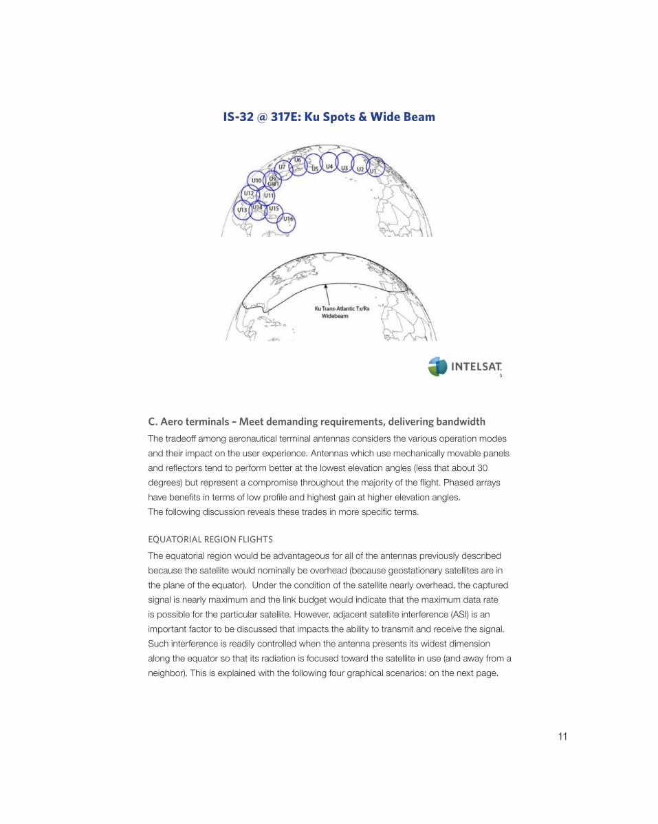
The ability of a particular GEO satellite to serve some portion of the earth is given by its coverage or footprint. On the next page you will see examples of the two types of footprints as provided by the Intelsat 32e satellite: spot beam coverage and widebeam coverage. The majority of satellites currently in use employ the widebeam where the user can appear literally anywhere within the footprint and will be relayed to any other point without reconfiguration of the satellite or other involvement of the satellite operator. On the other, the beam spreads the power over the widest area, resulting in a lower intensity which must be made up by the size of the user antenna and transmitter. The spot beam approach (found on high throughput satellites) addresses this latter point because the energy is more tightly focused and its intensity increases in direct proportion (actually, it is an inverse relationship based on the area of the beam). This will tend to reduce the size of antenna on the aircraft or, alternatively, increase the amount of data that can be transferred per unit time. A second and often more important benefit of spot beams is that the spectrum can be reused to provide more bandwidth overall and at a reduced cost per MHz. The satellite operator can pass this along in the form of a discount. Gateways need to be strategically located to take advantage of good Internet access. The widebeam coverage facilitates gateway placement while spot beams may or may not pose restrictions. Spot beams require the satellite network to hand-off aircraft as they move from beam to beam.
11
C. Aero terminals – Meet demanding requirements, delivering bandwidth
The tradeoff among aeronautical terminal antennas considers the various operation modes and their impact on the user experience. Antennas which use mechanically movable panels and reflectors tend to perform better at the lowest elevation angles (less that about 30 degrees) but represent a compromise throughout the majority of the flight. Phased arrays have benefits in terms of low profile and highest gain at higher elevation angles. The following discussion reveals these trades in more specific terms.
EQUATORIAL REGION FLIGHTS
The equatorial region would be advantageous for all of the antennas previously described because the satellite would nominally be overhead (because geostationary satellites are in the plane of the equator). Under the condition of the satellite nearly overhead, the captured signal is nearly maximum and the link budget would indicate that the maximum data rate is possible for the particular satellite. However, adjacent satellite interference (ASI) is an important factor to be discussed that impacts the ability to transmit and receive the signal. Such interference is readily controlled when the antenna presents its widest dimension along the equator so that its radiation is focused toward the satellite in use (and away from a neighbor). This is explained with the following four graphical scenarios: on the next page.
IS-32 @ 317E: Ku Spots & Wide Beam
12
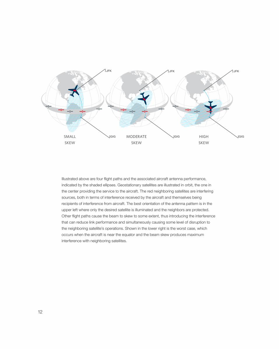
Illustrated above are four flight paths and the associated aircraft antenna performance, indicated by the shaded ellipses. Geostationary satellites are illustrated in orbit, the one in the center providing the service to the aircraft. The red neighboring satellites are interfering sources, both in terms of interference received by the aircraft and themselves being recipients of interference from aircraft. The best orientation of the antenna pattern is in the upper left where only the desired satellite is illuminated and the neighbors are protected. Other flight paths cause the beam to skew to some extent, thus introducing the interference that can reduce link performance and simultaneously causing some level of disruption to the neighboring satellite’s operations. Shown in the lower right is the worst case, which occurs when the aircraft is near the equator and the beam skew produces maximum interference with neighboring satellites.
JFKJFKJFK
GIGGIGGIGSMALL
SKEW
HIGH
SKEW
MODERATE
SKEW
13
JFK
GIG
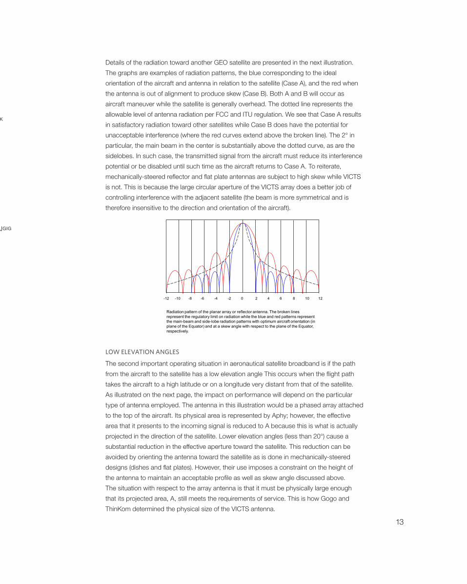
Radiation pattern of the planar array or reflector antenna. The broken lines represent the regulatory limit on radiation while the blue and red patterns represent the main-beam and side-lobe radiation patterns with optimum aircraft orientation (in plane of the Equator) and at a skew angle with respect to the plane of the Equator, respectively.
-12 -10 -8 -6 -4 -2 0 2 4 6 8 10 12
Details of the radiation toward another GEO satellite are presented in the next illustration. The graphs are examples of radiation patterns, the blue corresponding to the ideal orientation of the aircraft and antenna in relation to the satellite (Case A), and the red when the antenna is out of alignment to produce skew (Case B). Both A and B will occur as aircraft maneuver while the satellite is generally overhead. The dotted line represents the allowable level of antenna radiation per FCC and ITU regulation. We see that Case A results in satisfactory radiation toward other satellites while Case B does have the potential for unacceptable interference (where the red curves extend above the broken line). The 2° in particular, the main beam in the center is substantially above the dotted curve, as are the sidelobes. In such case, the transmitted signal from the aircraft must reduce its interference potential or be disabled until such time as the aircraft returns to Case A. To reiterate, mechanically-steered reflector and flat plate antennas are subject to high skew while VICTS is not. This is because the large circular aperture of the VICTS array does a better job of controlling interference with the adjacent satellite (the beam is more symmetrical and is therefore insensitive to the direction and orientation of the aircraft).
LOW ELEVATION ANGLES
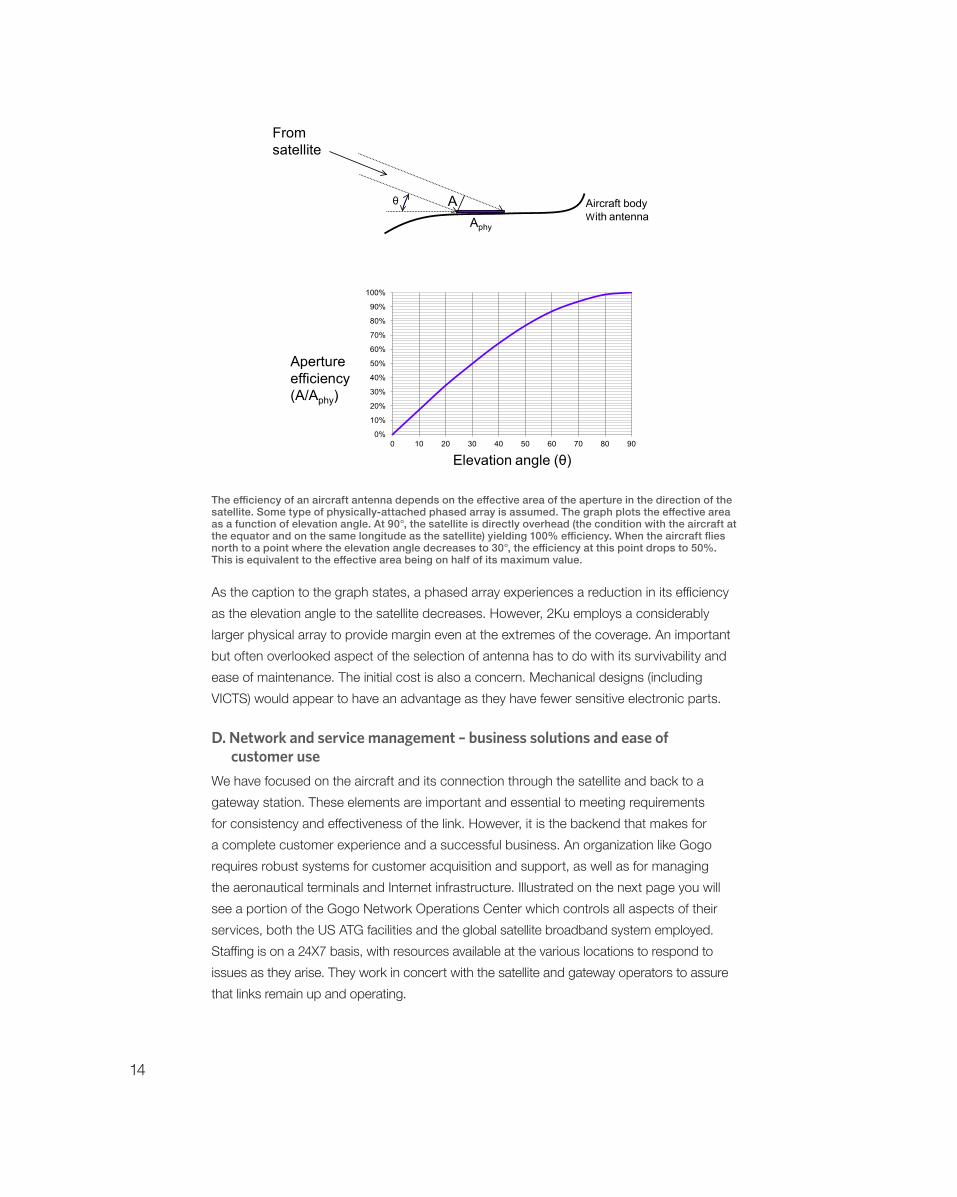
The second important operating situation in aeronautical satellite broadband is if the path from the aircraft to the satellite has a low elevation angle This occurs when the flight path takes the aircraft to a high latitude or on a longitude very distant from that of the satellite. As illustrated on the next page, the impact on performance will depend on the particular type of antenna employed. The antenna in this illustration would be a phased array attached to the top of the aircraft. Its physical area is represented by Aphy; however, the effective area that it presents to the incoming signal is reduced to A because this is what is actually projected in the direction of the satellite. Lower elevation angles (less than 20°) cause a substantial reduction in the effective aperture toward the satellite. This reduction can be avoided by orienting the antenna toward the satellite as is done in mechanically-steered designs (dishes and flat plates). However, their use imposes a constraint on the height of the antenna to maintain an acceptable profile as well as skew angle discussed above. The situation with respect to the array antenna is that it must be physically large enough that its projected area, A, still meets the requirements of service. This is how Gogo and ThinKom determined the physical size of the VICTS antenna.
14
θ AAphy
0%
10%
20%
30%
40%
50%
60%
70%
80%
90%
100%
0 10 20 30 40 50 60 70 80 90
Apertureefficiency(A/Aphy)
Elevation angle (θ)
Fromsatellite
Aircraft bodyWith antenna
θ AAphy
0%
10%
20%
30%
40%
50%
60%
70%
80%
90%
100%
0 10 20 30 40 50 60 70 80 90
Apertureefficiency(A/Aphy)
Elevation angle (θ)
Fromsatellite
Aircraft bodyWith antenna
The efficiency of an aircraft antenna depends on the effective area of the aperture in the direction of the satellite. Some type of physically-attached phased array is assumed. The graph plots the effective area as a function of elevation angle. At 90°, the satellite is directly overhead (the condition with the aircraft at the equator and on the same longitude as the satellite) yielding 100% efficiency. When the aircraft flies north to a point where the elevation angle decreases to 30°, the efficiency at this point drops to 50%. This is equivalent to the effective area being on half of its maximum value.
As the caption to the graph states, a phased array experiences a reduction in its efficiency as the elevation angle to the satellite decreases. However, 2Ku employs a considerably larger physical array to provide margin even at the extremes of the coverage. An important but often overlooked aspect of the selection of antenna has to do with its survivability and ease of maintenance. The initial cost is also a concern. Mechanical designs (including VICTS) would appear to have an advantage as they have fewer sensitive electronic parts.
D. Network and service management – business solutions and ease of customer use
We have focused on the aircraft and its connection through the satellite and back to a gateway station. These elements are important and essential to meeting requirements for consistency and effectiveness of the link. However, it is the backend that makes for a complete customer experience and a successful business. An organization like Gogo requires robust systems for customer acquisition and support, as well as for managing the aeronautical terminals and Internet infrastructure. Illustrated on the next page you will see a portion of the Gogo Network Operations Center which controls all aspects of their services, both the US ATG facilities and the global satellite broadband system employed. Staffing is on a 24X7 basis, with resources available at the various locations to respond to issues as they arise. They work in concert with the satellite and gateway operators to assure that links remain up and operating.

15
IV. Antenna Technology – Critical to Service ContinuityHaving well established infrastructure and operating capabilities, Gogo needed to be sure that the antenna solution was right. The options other than VICTS were well known, but all had significant deficiencies when examining the requirements and where the market trajectory. This section describes the options and detailed trades that led to the selection of VICTS for 2Ku.
B. Mechanically steered vs. electrically steered antennas – strengths and weaknesses
There are literally dozens of tracking antenna systems being offered for use on aircraft. Most have fundamental limitations, such as providing receive-only performance or operating in spectrum such as L band which is not suitable for broadband. We can thus narrow the field to perhaps six candidates. Gogo already is employing a type of mechanically steered antenna composed of a set of feedhorns. The dish and flat panel are also a mechanically-steered approach. Boeing employed an electronic phased array fixed to the aircraft body. Finally, the VICTS approach from ThinKom, which was developed for the more demanding vehicular satellite broadband market, is considered for its advantages in relation to the prior techniques.
ELECTRONIC PHASED ARRAY
The electronic phased array was developed over an extended period and has been used in early systems for aeronautical communications. Individual radiation fields from the elements form a resultant beam that can be directed toward the satellite independently of aircraft orientation. Beam direction is determined by complex coefficients applied to the elements; direction is changed by modifying the coefficients. The data provided by a manufacturer indicates that the system is intended to function for elevation angles ranging from 90° (which is ideal in that there is no loss due to aperture efficiency) down to 30° (corresponding to a loss of 50%). An airplane would not be able to provide service for higher latitudes or if the longitude is substantially different from that of the satellite. The latter would necessitate more satellites while the former cannot be overcome when using the phased array. Performance can be improved by increasing the quantity of elements in expanding the overall area. However, this is a costly endeavor and increases the complexity of the device.

16
REFLECTOR ANTENNA
The reflector antenna has the ability to direct a consistent beam to the satellite location relative to the airplane. The downside occurs when the aircraft is near the equator in which case its potential to cause ASI increases due to skew. The reflector also tends to have a high profile relative to other designs.
FLAT PANEL
Some of the complexities with the reflector system can be resolved with the mechanically-steered flat panel. This bi-directional antenna system mounts on the top of the aircraft fuselage under a radome; the antenna control unit and the high-power transceiver are generally mounted inside the fuselage. The design benefits from not employing a feed system that would cause the profile to increase. However, it suffers from ASI as the reflector when the aircraft operates near the equator. An array of fixed microwave horns can be employed as an alternative, providing the same performance for a given aperture. Like the reflector and planar array, the horn array has a flattened aperture when it is along the plane of the equator. However, when the aircraft tilts so that the beam becomes skewed, the resulting beam will introduce more ASI.
VICTS MECHANICAL PHASED ARRAY
ThinKom has a unique design to satisfy Gogo’s requirements for an aeronautical broadband antenna system, illustrated later in this document. The basic aperture is circular and its area can be made as large as the aircraft permits. The two-dimensional scan mechanism for the VICTS array involves the simple rotation (common and differential) of two coplanar plates, one (upper) comprised of a one-dimensional lattice of continuous radiating stubs and the second (lower) comprised of one or more static line-sources. Mechanical rotation of the upper plate relative to the lower changes the scan angle in elevation. Common rotation of the two plates in unison changes the azimuth direction. Polarization control and diversity is supported by adding a third polarizer layer to alter the angle of linear polarization.
Like the Boeing electronic phased array, VICTS is at its best in the equatorial region where the area presented toward the satellite is maximum. With an enlarged capture area provided by the concentric circular plates, the effective gain of the antenna is still competitive with mechanically steered antennas (reflector, plate and horn arrays) for the majority of flights. This will be discussed later in this paper. In addition, the antenna has one of the lowest profiles.

17
EMERGING TECHNOLOGIES FOR AERONAUTICAL ANTENNAS
There are a few technologies currently in R&D that could provide useful features in the coming years. These include flat or conformal phased arrays based on metamaterials and on IF combining. Beam redirection is achieved in metamaterials through the use of a standard printed circuit board composed of several thousand sub-wavelength resonators that can be individually tuned. The resulting array has a very low profile and can be placed either on the top or potentially in pairs on the opposite sides of the aircraft. The other new approach uses miniature amplifier elements along with frequency converters; the phasing aspects are done at lower frequencies. Like the metameterial approach, IF combining can be produced in a thin package and could allow placement on top or the sides of an aircraft.
C. Comparison of Access Technologies
To provide some clarity on how the various technologies address the most important figures of merit, we provide a summary chart for side-by-side comparison. The Electronic Array in the first column of alternatives refers to the Boeing type of design which is rigidly attached to the aircraft body. On the other hand the Reflector and the Flat Panel (or Horn Array) must be mechanically directed with a motorized tracking system. Lastly, VICTS technology employs mechanically movable disks but is not physically directed toward the satellite. The code to the colors is as follows:
Green – meets the requirements in a robust mannerYellow – partially meets the requirementsRed – does not meet the requirementsmajority of requirements in a robust manner, with some limitations such as operation near the poles on a partial basis (mainly due to limitation of satellite coverage). The reflector and flat panel, both being mechanically-steered, meet requirements under some conditions (northern latitudes and rugged design), while the electronic phased array provides the least favorable characteristics relative to the requirements for aeronautical broadband service.
V. 2Ku Aeronautical Antenna Design DetailsThe tradeoffs among the various aeronautical platforms and antenna technologies have been presented in the context of the Gogo service and business model. At this point, we address the salient design characteristics of the antenna system provided by ThinKom and using VICTS. From there, we consider the in-flight characteristics realized by this platform and how it performs in service throughout the commercial flight experience.
18
A. 2Ku Design Characteristics
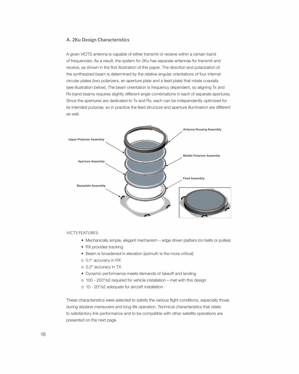
A given VICTS antenna is capable of either transmit or receive within a certain band of frequencies. As a result, the system for 2Ku has separate antennas for transmit and receive, as shown in the first illustration of this paper. The direction and polarization of the synthesized beam is determined by the relative angular orientations of four internal circular plates (two polarizers, an aperture plate and a feed plate) that rotate coaxially (see illustration below). The beam orientation is frequency dependent, so aligning Tx and Rx band beams requires slightly different angle combinations in each of separate apertures. Since the apertures are dedicated to Tx and Rx, each can be independently optimized for its intended purpose, so in practice the feed structure and aperture illumination are different as well.
VICTS FEATURES:
• Mechanically simple, elegant mechanism – edge driven platters (no belts or pullies) • RX provides tracking • Beam is broadened in elevation (azimuth is the more critical) o 0.1° accuracy in RX o 0.2° accuracy in TX • Dynamic performance meets demands of takeoff and landing o 100 - 200°/s2 required for vehicle installation – met with this design o 10 - 20°/s2 adequate for aircraft installation
These characteristics were selected to satisfy the various flight conditions, especially those during airplane maneuvers and long-life operation. Technical characteristics that relate to satisfactory link performance and to be compatible with other satellite operations are presented on the next page.
Upper Polarizer Assembly
Aperture Assembly
Baseplate Assembly
Antenna Housing Assembly
Middle Polarizer Assembly
Feed Assembly
19
B. Performance CharacteristicsFORWARD LINK – G/T – IMPORTANT FOR DATA DELIVERY TO THE AIRCRAFT
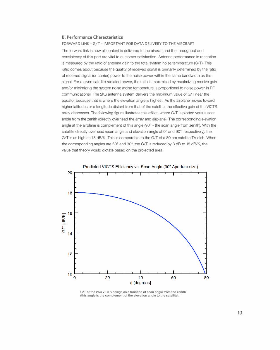
The forward link is how all content is delivered to the aircraft and the throughput and consistency of this part are vital to customer satisfaction. Antenna performance in reception is measured by the ratio of antenna gain to the total system noise temperature (G/T). This ratio comes about because the quality of received signal is primarily determined by the ratio of received signal (or carrier) power to the noise power within the same bandwidth as the signal. For a given satellite radiated power, the ratio is maximized by maximizing receive gain and/or minimizing the system noise (noise temperature is proportional to noise power in RF communications). The 2Ku antenna system delivers the maximum value of G/T near the equator because that is where the elevation angle is highest. As the airplane moves toward higher latitudes or a longitude distant from that of the satellite, the effective gain of the VICTS array decreases. The following figure illustrates this effect, where G/T is plotted versus scan angle from the zenith (directly overhead the array and airplane). The corresponding elevation angle at the airplane is complement of this angle (90° - the scan angle from zenith). With the satellite directly overhead (scan angle and elevation angle at 0° and 90°, respectively), the G/T is as high as 18 dB/K. This is comparable to the G/T of a 80 cm satellite TV dish. When the corresponding angles are 60° and 30°, the G/T is reduced by 3 dB to 15 dB/K, the value that theory would dictate based on the projected area.
G/T of the 2Ku VICTS design as a function of scan angle from the zenith (this angle is the complement of the elevation angle to the satellite).

20
The overall performance of the link is impacted both by the G/T and the adjacent satellite interference (ASI), the later resulting from radiation into the aircraft antenna from satellites in adjacent orbit locations. This is presented in the color-coded diagrams below, by the effective G/T (including gain, noise, interference, and noise added by the atmosphere at low elevation angles). The satellite is located at the center of the diagram, and aircraft would be at positions throughout the colored zone of coverage. Acceptable values are indicated by colors ranging from orange (good) through dark red (best); green is marginal, and blue would be consistent with degraded performance or a ineffective link. The presentation for VICTS on the left demonstrates good to excellent performance in the presence of ASI at elevation angles down to 30° and from the equator to latitudes approaching 70°. The current state of the art flat panel antenna, presented on the right, has substantially poorer performance over the same flight conditions due to lower gain and the presence of ASI: most of the region of coverage is at marginal G/T and drops below acceptability along the equator (deep blue) and at the high latitudes. In all cases, VICTS performs best, especially when the plane experiences high skew angles toward the satellite. The previous illustrations of flight paths and the associated beam orientations testify to the merits of VICTS in the presence of ASI.
RETURN LINK – EIRP AND POWER SPECTRAL DENSITY
The crucial parameter for the transmit VICTS antenna (which is physically separate but follows the direction of the receive antenna) is the effective isotropic radiated power (EIRP). This is equal to the power in RF watts that is directed toward the satellite and hence matters in the return data rate of transmission. With a transmit gain comparable to receive and an appropriate microwave power amplifier, almost any value of EIRP can be achieved. For example, a 40 watt amplifier can produce approximately 55 dBW if the beam is directed toward the zenith or 52 dBW at an elevation angle of 30°. These values must be reflected in the link budget calculations. At the same time, we must consider the potential interference that could be caused to an adjacent satellite 2° away. Similar ground rules apply to the state-of-the-art alternative antennas.
21
C. Azimuth beamwidth is constant
The critical dimension of the beam is its angular width along the equatorial arc. This is the arc where the currently operating satellite is positioned as well as the nearest neighboring satellites. With 2° spacing, the onus is on the azimuth beamwidth to produce the acceptable level of radiation toward these neighbors. This beamwidth for VICTS is a constant as azimuth and elevation are varied. The significant variation that must be taken into account is the aperture efficiency due to change in the elevation angle toward the satellite, which is addressed by the larger physical aperture of the circular disk array.
D. Broadband throughput and availability
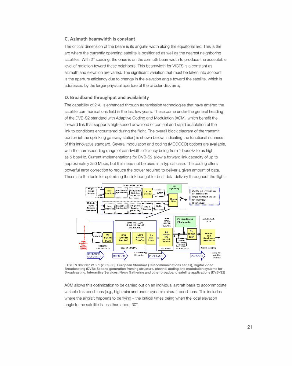
The capability of 2Ku is enhanced through transmission technologies that have entered the satellite communications field in the last few years. These come under the general heading of the DVB-S2 standard with Adaptive Coding and Modulation (ACM), which benefit the forward link that supports high-speed download of content and rapid adaptation of the link to conditions encountered during the flight. The overall block diagram of the transmit portion (at the uplinking gateway station) is shown below, indicating the functional richness of this innovative standard. Several modulation and coding (MODCOD) options are available, with the corresponding range of bandwidth efficiency being from 1 bps/Hz to as high as 5 bps/Hz. Current implementations for DVB-S2 allow a forward link capacity of up to approximately 250 Mbps, but this need not be used in a typical case. The coding offers powerful error correction to reduce the power required to deliver a given amount of data. These are the tools for optimizing the link budget for best data delivery throughout the flight.
ETSI EN 302 307 V1.2.1 (2009-08), European Standard (Telecommunications series), Digital Video Broadcasting (DVB); Second generation framing structure, channel coding and modulation systems for Broadcasting, Interactive Services, News Gathering and other broadband satellite applications (DVB-S2)
ACM allows this optimization to be carried out on an individual aircraft basis to accommodate variable link conditions (e.g., high rain) and under dynamic aircraft conditions. This includes where the aircraft happens to be flying – the critical times being when the local elevation angle to the satellite is less than about 30°.

22
E. Next best alternative – how does it stack up?
Gogo was in a position to choose the “best in breed” for the aircraft antenna system and is integrating it into their state-of-the art aeronautical broadband network. As discussed previously, Gogo has combined the ATG network with a global satellite-relay capability to serve the commercial aviation market with high-throughput transmission. The previous comparative color-coded chart allows us to determine the next best alternative to VICTS and this is the mechanically-directed flat panel antenna. However, this approach suffers from the same issues as both the reflector and the horn-array antenna previously employed by Gogo – that is, the antenna produces excessive interference into and from the adjacent satellite during aircraft maneuvers. The latter occurs in proximity to the equator and under extremes near the poles. Furthermore, VICTS delivers higher G/T under almost all flight conditions.
If we were to compare 2Ku with the best alternative, it could be representative with the illustration of overall efficiency vs. elevation angle, as shown below.
The following observations can be made from this comparison regarding 2Ku: • 2Ku offers better performance than the best alternative everywhere above 10° elevation (operation is still possible below 10° with reduced throughput)• 2Ku is dramatically better in terms of capability over high density flight route areas.
The consequence of the second bullet point is that service to the passenger will be substantially greater data rates – by a factor of two or more – than the best alternative.This will be over the majority of flight routes and durations.

23
VI. ConclusionsAeronautical broadband is moving ahead and can rely on a solid technical foundation. This consists of high-performance Ku band geostationary satellites that serve many markets and are particularly attractive for this application. The 2Ku approach using VICTS can exploit the bandwidth from currently available Ku satellites as well as those employing spot beams and enhanced frequency reuse.
IN SUMMARY, 2KU DELIVERS:
• Highest gain/efficiency over current state-of-the-art antennas • Immune to skew angle phenomenon experienced during flight periods • Compatible with existing Ku band satellites as well as the new generation of High Throughput Satellites now being launched • Economical, rugged design • Low profile for least fuel/range/payload penalty • Few moving parts = higher reliability = least maintenance/repair expenses over life of product • Inherently superior performance in terms of satellite transmission and data throughput means that it does not need to be replaced to evolve with continuous performance improvements in the future
The next three to five years are crucial to bringing this to fruition and Gogo is making the appropriate investments into the technology and partnership relationships. Leading satellite operators are also making large investments in new space relay platforms so that Gogo can move ahead by concentrating on its infrastructure. As a consequence of the tradeoff, Gogo 2Ku is providing the most cost/effective solution, now and in the coming decade