Gebl−se - Gasbrenner GB Forced draught gas burnersprodukte.riello-sachsen.de/brenner/anleitung/RS...
42
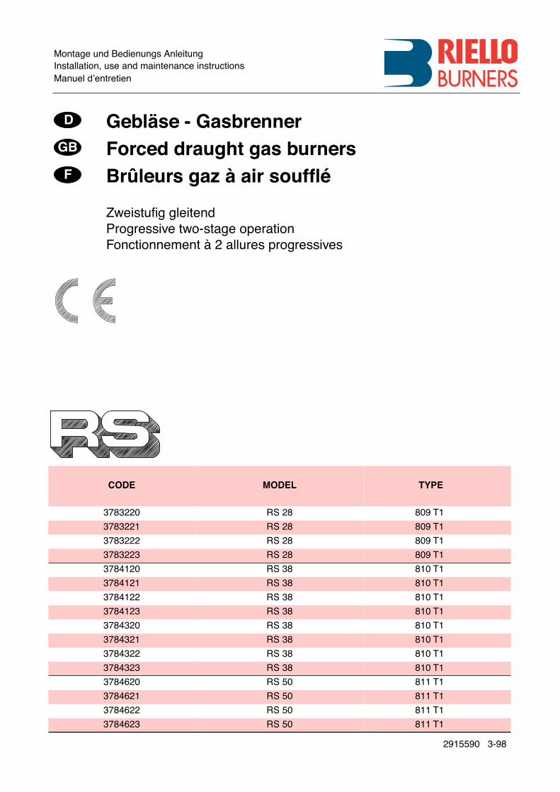
Montage und Bedienungs Anleitung Installation, use and maintenance instructions Manuel dentretien Geblse - Gasbrenner Forced draught gas burners Brleurs gaz air souf 2915590 3-98 CODE MODEL TYPE 3783220 RS 28 809 T1 3783221 RS 28 809 T1 3783222 RS 28 809 T1 3783223 RS 28 809 T1 3784120 RS 38 810 T1 3784121 RS 38 810 T1 3784122 RS 38 810 T1 3784123 RS 38 810 T1 3784320 RS 38 810 T1 3784321 RS 38 810 T1 3784322 RS 38 810 T1 3784323 RS 38 810 T1 3784620 RS 50 811 T1 3784621 RS 50 811 T1 3784622 RS 50 811 T1 3784623 RS 50 811 T1 D GB F Zweistug gleitend Progressive two-stage operation Fonctionnement 2 allures progressives
Transcript of Gebl−se - Gasbrenner GB Forced draught gas burnersprodukte.riello-sachsen.de/brenner/anleitung/RS...
Montage und Bedienungs AnleitungInstallation, use and maintenance instructionsManuel dÕentretien
Gebl�se - GasbrennerForced draught gas burnersBr�leurs gaz � air souf�
2915590 3-98
CODE MODEL TYPE
3783220 RS 28 809 T1
3783221 RS 28 809 T1
3783222 RS 28 809 T1
3783223 RS 28 809 T1
3784120 RS 38 810 T1
3784121 RS 38 810 T1
3784122 RS 38 810 T1
3784123 RS 38 810 T1
3784320 RS 38 810 T1
3784321 RS 38 810 T1
3784322 RS 38 810 T1
3784323 RS 38 810 T1
3784620 RS 50 811 T1
3784621 RS 50 811 T1
3784622 RS 50 811 T1
3784623 RS 50 811 T1
D
GB
F
ZweistuÞg gleitendProgressive two-stage operationFonctionnement � 2 allures progressives

2
INHALT
TECHNISCHE ANGABEN
. . . . . . . . . . . . . . . . . . . . . . . . . Seite
3
Bauvarianten . . . . . . . . . . . . . . . . . . . . . . . . . . . . . . . . . . . . . . . . 3Zubeh�r . . . . . . . . . . . . . . . . . . . . . . . . . . . . . . . . . . . . . . . . . . . . 3Brennerbeschreibung . . . . . . . . . . . . . . . . . . . . . . . . . . . . . . . . . . 6Verpackung - Gewicht . . . . . . . . . . . . . . . . . . . . . . . . . . . . . . . . . 6Abmessungen . . . . . . . . . . . . . . . . . . . . . . . . . . . . . . . . . . . . . . . 6Ausstattung . . . . . . . . . . . . . . . . . . . . . . . . . . . . . . . . . . . . . . . . . 6Regelbereiche . . . . . . . . . . . . . . . . . . . . . . . . . . . . . . . . . . . . . . . 8Pr�fkessel. . . . . . . . . . . . . . . . . . . . . . . . . . . . . . . . . . . . . . . . . . . 8Handels�bliche Kessel . . . . . . . . . . . . . . . . . . . . . . . . . . . . . . . . . 8Gasdruck . . . . . . . . . . . . . . . . . . . . . . . . . . . . . . . . . . . . . . . . . . 10
INSTALLATION . . . . . . . . . . . . . . . . . . . . . . . . . . . . . . . . . . . . . 12
Kesselplatte . . . . . . . . . . . . . . . . . . . . . . . . . . . . . . . . . . . . . . . . 12Flammrohrl�nge . . . . . . . . . . . . . . . . . . . . . . . . . . . . . . . . . . . . . 12Befestigung des Brenners am Heizkessel . . . . . . . . . . . . . . . . . 12Einstellung des Flammkopfs . . . . . . . . . . . . . . . . . . . . . . . . . . . 14Gaszuleitung . . . . . . . . . . . . . . . . . . . . . . . . . . . . . . . . . . . . . . . 16Elektroanlage . . . . . . . . . . . . . . . . . . . . . . . . . . . . . . . . . . . . . . . 18Einstellungen vor der Z�ndung . . . . . . . . . . . . . . . . . . . . . . . . . 24Anfahren des Brenners . . . . . . . . . . . . . . . . . . . . . . . . . . . . . . . 24Z�ndung des Brenners. . . . . . . . . . . . . . . . . . . . . . . . . . . . . . . . 24Brennereinstellung: . . . . . . . . . . . . . . . . . . . . . . . . . . . . . . . . . . 261 - Z�ndleistung . . . . . . . . . . . . . . . . . . . . . . . . . . . . . . . . . . . . . 262 - Leistung auf 2. Stufe . . . . . . . . . . . . . . . . . . . . . . . . . . . . . . . 263 - Leistung auf 1. Stufe . . . . . . . . . . . . . . . . . . . . . . . . . . . . . . . 284 - Zwischenleistungen. . . . . . . . . . . . . . . . . . . . . . . . . . . . . . . . 285 - Luft-Druckw�chter . . . . . . . . . . . . . . . . . . . . . . . . . . . . . . . . . 306 - Gas-Minimaldruckw�chter. . . . . . . . . . . . . . . . . . . . . . . . . . . 30Flammen�berwachung. . . . . . . . . . . . . . . . . . . . . . . . . . . . . . . . 30Brennerbetrieb . . . . . . . . . . . . . . . . . . . . . . . . . . . . . . . . . . . . . . 32Endkontrollen . . . . . . . . . . . . . . . . . . . . . . . . . . . . . . . . . . . . . . . 34Wartung . . . . . . . . . . . . . . . . . . . . . . . . . . . . . . . . . . . . . . . . . . . 34STATUS/LED PANEL . . . . . . . . . . . . . . . . . . . . . . . . . . . . . . . . . 36St�rungen - Ursachen - Abhilfen . . . . . . . . . . . . . . . . . . . . . . . . 38
Anmerkung
Die Zeichnungen, auf die im Text Bezug genommen wird, werdenfolgenderma§en bezeichnet:1)(A) =Detail 1 der Zeichnung A auf der gleichen Textseite;1)(A)S.6 =Detail 1 der Zeichnung A auf Seite 6.
In Konformit�t mit der Wirkungsgradrichtlinie 92/42/EWG m�s-sen die Anbringung des Brenners am Heizkessel, die Einstellungund die Inbetriebnahme unter Beachtung der Betriebsanleitungder Heizkessels ausgef�hrt werden, einschlie§lich Kontrolle derKonzentration von CO und CO
2
in den Abgasen, ihrer Tempera-tur und der mittlenen Kesseltemperatur.
I
CONTENTS
TECHNICAL DATA
. . . . . . . . . . . . . . . . . . . . . . . . . . . . . . . page
4
Variants . . . . . . . . . . . . . . . . . . . . . . . . . . . . . . . . . . . . . . . . . . . . . 4Accessories. . . . . . . . . . . . . . . . . . . . . . . . . . . . . . . . . . . . . . . . . . 4Burner description. . . . . . . . . . . . . . . . . . . . . . . . . . . . . . . . . . . . . 7Packaging - Weight . . . . . . . . . . . . . . . . . . . . . . . . . . . . . . . . . . . . 7Max. dimensions . . . . . . . . . . . . . . . . . . . . . . . . . . . . . . . . . . . . . . 7Standard equipment . . . . . . . . . . . . . . . . . . . . . . . . . . . . . . . . . . . 7Firing rates . . . . . . . . . . . . . . . . . . . . . . . . . . . . . . . . . . . . . . . . . . 9Test boiler . . . . . . . . . . . . . . . . . . . . . . . . . . . . . . . . . . . . . . . . . . . 9Commercial boilers . . . . . . . . . . . . . . . . . . . . . . . . . . . . . . . . . . . . 9Gas pressure. . . . . . . . . . . . . . . . . . . . . . . . . . . . . . . . . . . . . . . . 11
INSTALLATION . . . . . . . . . . . . . . . . . . . . . . . . . . . . . . . . . . . . . 13
Boiler plate . . . . . . . . . . . . . . . . . . . . . . . . . . . . . . . . . . . . . . . . . 13Blast tube length . . . . . . . . . . . . . . . . . . . . . . . . . . . . . . . . . . . . 13Securing the burner to the boiler. . . . . . . . . . . . . . . . . . . . . . . . . 13Setting the combustion head . . . . . . . . . . . . . . . . . . . . . . . . . . . 15Gas line . . . . . . . . . . . . . . . . . . . . . . . . . . . . . . . . . . . . . . . . . . . . 17Electrical system . . . . . . . . . . . . . . . . . . . . . . . . . . . . . . . . . . . . . 19Adjustments before Þring . . . . . . . . . . . . . . . . . . . . . . . . . . . . . . 25Burner starting . . . . . . . . . . . . . . . . . . . . . . . . . . . . . . . . . . . . . . 25Burner Þring . . . . . . . . . . . . . . . . . . . . . . . . . . . . . . . . . . . . . . . . 25Burner calibration: . . . . . . . . . . . . . . . . . . . . . . . . . . . . . . . . . . . . 271 - Firing output . . . . . . . . . . . . . . . . . . . . . . . . . . . . . . . . . . . . . . 272 - 2nd stage output . . . . . . . . . . . . . . . . . . . . . . . . . . . . . . . . . . 273 - 1st stage output . . . . . . . . . . . . . . . . . . . . . . . . . . . . . . . . . . . 294 - Intermediates outputs . . . . . . . . . . . . . . . . . . . . . . . . . . . . . . 295 - Air pressure switch. . . . . . . . . . . . . . . . . . . . . . . . . . . . . . . . . 316 - Minimum gas pressure switch . . . . . . . . . . . . . . . . . . . . . . . . 31Flame present check. . . . . . . . . . . . . . . . . . . . . . . . . . . . . . . . . . 27Burner operation . . . . . . . . . . . . . . . . . . . . . . . . . . . . . . . . . . . . . 33Final checks . . . . . . . . . . . . . . . . . . . . . . . . . . . . . . . . . . . . . . . . 35Maintenance . . . . . . . . . . . . . . . . . . . . . . . . . . . . . . . . . . . . . . . . 35STATUS/LED PANEL. . . . . . . . . . . . . . . . . . . . . . . . . . . . . . . . . . 37Fault - Probable cause - Suggested remedy. . . . . . . . . . . . . . . . 39
N.B.
Figures mentioned in the text are identiÞed as follows:1)(A) =part 1 of Þgure A, same page as text;1)(A)p.6 =part 1 of Þgure A, page number 6.
In conformity with EfÞciency Directive 92/42/EEC the applicationof the burner on the boiler, adjustment and testing must be car-ried out observing the instruction manual of the boiler, includingveriÞcation of the CO and CO
2
concentration in the ßue gases,their temperatures and the average temperature of the water inthe boiler.
GB
INDEX
DONN�ES TECHNIQUES
. . . . . . . . . . . . . . . . . . . . . . . . . page
5
Mod�les disponibles. . . . . . . . . . . . . . . . . . . . . . . . . . . . . . . . . . . 5Accesoires . . . . . . . . . . . . . . . . . . . . . . . . . . . . . . . . . . . . . . . . . . 5Description br�leur . . . . . . . . . . . . . . . . . . . . . . . . . . . . . . . . . . . . 7Emballage - Poids . . . . . . . . . . . . . . . . . . . . . . . . . . . . . . . . . . . . 7Encombrement . . . . . . . . . . . . . . . . . . . . . . . . . . . . . . . . . . . . . . . 7Equipement standard . . . . . . . . . . . . . . . . . . . . . . . . . . . . . . . . . . 7Plages de puissance . . . . . . . . . . . . . . . . . . . . . . . . . . . . . . . . . . 9Chaudi�re dÕessai. . . . . . . . . . . . . . . . . . . . . . . . . . . . . . . . . . . . . 9Chaudi�res commerciales . . . . . . . . . . . . . . . . . . . . . . . . . . . . . . 9Pression du gaz . . . . . . . . . . . . . . . . . . . . . . . . . . . . . . . . . . . . . 11
INSTALLATION . . . . . . . . . . . . . . . . . . . . . . . . . . . . . . . . . . . . . 13
Plaque chaudi�re . . . . . . . . . . . . . . . . . . . . . . . . . . . . . . . . . . . . 13Longueur buse . . . . . . . . . . . . . . . . . . . . . . . . . . . . . . . . . . . . . 13Fixation du br�leur � la chaudi�re . . . . . . . . . . . . . . . . . . . . . . . 13R�glage t�te de combustion. . . . . . . . . . . . . . . . . . . . . . . . . . . . 15Ligne alimentation gaz . . . . . . . . . . . . . . . . . . . . . . . . . . . . . . . . 17Installation �lectrique . . . . . . . . . . . . . . . . . . . . . . . . . . . . . . . . . 19R�glages avant lÕallumage . . . . . . . . . . . . . . . . . . . . . . . . . . . . . 25D�marrage br�leur . . . . . . . . . . . . . . . . . . . . . . . . . . . . . . . . . . . 25Allumage br�leur . . . . . . . . . . . . . . . . . . . . . . . . . . . . . . . . . . . . 25R�glage br�leur:. . . . . . . . . . . . . . . . . . . . . . . . . . . . . . . . . . . . . 271 - Puissance � lÕallumage . . . . . . . . . . . . . . . . . . . . . . . . . . . . . 272 - Puissance en 2�me allure. . . . . . . . . . . . . . . . . . . . . . . . . . . 273 - Puissance en 1�re allure. . . . . . . . . . . . . . . . . . . . . . . . . . . . 294 - Puissances interm�diares. . . . . . . . . . . . . . . . . . . . . . . . . . . 295 - Pressostat de lÕair . . . . . . . . . . . . . . . . . . . . . . . . . . . . . . . . . 316 - Pressostat gaz seuil minimum . . . . . . . . . . . . . . . . . . . . . . . 31Contr�le pr�sence ßamme . . . . . . . . . . . . . . . . . . . . . . . . . . . . . 31Fonctionnement br�leur . . . . . . . . . . . . . . . . . . . . . . . . . . . . . . . 33Contr�les Þnaux . . . . . . . . . . . . . . . . . . . . . . . . . . . . . . . . . . . . . 35Entretien . . . . . . . . . . . . . . . . . . . . . . . . . . . . . . . . . . . . . . . . . . . 35STATUS/LED PANEL . . . . . . . . . . . . . . . . . . . . . . . . . . . . . . . . . 37Inconv�nients - Causes - Rem�des . . . . . . . . . . . . . . . . . . . . . . 40
Attention
Les Þgures rappel�es dans le texte sont ainsi indiqu�es:1)(A) =D�tail 1 de la Þgure A dans la m�me page du texte;1)(A)p.6 =D�tail 1 de la Þgure A page 6.
Conform�ment � la Directive rendement 92/42/CEE, suivre lesindications du manuel de la chaudi�re pour monter le br�leur,effectuer le r�glage et lÕessai, contr�ler la concentration de CO etCO
2
, dans les fum�es, leur temp�rature et celle moyenne delÕeau de la chaudi�re.
F

3
TECHNISCHE ANGABEN
(1) Bezugsbedingungen: Raumtemperatur 20
°
C - Barometrischer Druck 1000 mbar - H�he 100 m �.d.M.(2) Druck am Anschlu§ 16)(A)S.6 bei druckloser Brennkammer, ge�ffneter Gasscheibe 2)(B)S.14 und bei H�chstleistung des Brenners.(3) Schalldruck, im Brennpr�ßabor des Herstellers mit Brenner auf Pr�fkessel bei H�chstleistung.
BAUVARIANTEN:
ZUBEH�R
(auf Wunsch):
¥
KIT F�R FL�SSIGGAS-BETRIEB:
Der Kit erlaubt den Brenner RS 28-38-50 Fl�ssiggas zu brennen.
¥
GASARMATUREN GEM�§ NORM EN 676 (mit Ventilen, Druckregel und Filter):
siehe Seite 16.
MODELL RS 28 RS 38 RS 38 RS 50
TYP 809 T1 810 T1 810 T1 811 T1
LEISTUNG
(1)
2. Stufe kW 163 - 325140 - 280
232 - 440200 - 378
232 - 440200 - 378
290 - 581249 - 500Mcal/h
min. 1. Stufe kWMcal/h
8170
10590
10590
116100
BRENNSTOFF ERDGAS: G20 - G21 - G22 - G23 - G25
G20 G25 G20 G25 G20 G25 G20 G25
- Unterer Heizwert Hu kWh/Nm
3
Mcal/Nm
3
108,6
8,67,4
108,6
8,67,4
108,6
8,67,4
108,6
8,67,4
- Reindichte kg/Nm
3
0,71 0,78 0,71 0,78 0,71 0,78 0,71 0,78
- H�chstdruchsatz Nm
3
/h 32 38 44 51 44 51 58 68
- Druck bei H�chstdruchsatz
(2)
mbar 7,5 11,1 6,6 9,7 6,6 9,7 7,2 10,6
BETRIEB ¥ Aussetzend (min. 1 Halt in 24 Stunden) ¥ ZweistuÞg (hohe und niedrige Flamme) - einsuÞg (alles - nichts)
STANDARDEINSATZ Heizkessel: mit Wasser, Dampf, diathermischem �l
RAUMTEMPERATUR
°
C 0 - 40
TEMPERATUR VERBRENNUNGSLUFT
°
C max 60
ELEKTRISCHE SPEISUNG VHz
230 ~ +/-10%50 - einphasing
230 - 400 mit Nulleiter ~ +/-10%50 - dreiphasing
ELEKTROMOTOR rpmWVA
2800250
220 - 2402,1
2800420
220 - 2402,9
2800450
220/240-380/4152 - 1,2
2800650
220/240-380/4153 - 1,7
MOTORKONDENSATOR
m
F/V 8/450 12,5/450
Z�NDTRANSFORMATOR V1 - V2I1 - I2
230 V - 1 x 8 kV1 A - 20 mA
ELEKTRISCHE LEISTUNGSAUFNAHME W max 370 600 560 750
SCHUTZART IP 44
CE - NORMGERECHT 90/396 - 89/336 - 73/23 - 92/42
SCHALLDRUCKPEGEL
(3)
dBA 68 70 70 72
TYPPR�FUNG CE 0085AP0733 0085AP0734 0085AP0734 0085AP0735
MODELL ELEKTRISCHESPEISUNG
FLAMMROHRL�NGE mm
STATUS /LED PANEL
RS 28
EinphasingEinphasingEinphasingEinphasing
216351216351
STATUSSTATUS
LED PANELLED PANEL
RS 38
EinphasingEinphasingEinphasingEinphasingDreiphasingDreiphasingDreiphasingDreiphasing
216351216351216351216351
STATUSSTATUS
LED PANELLED PANEL
STATUSSTATUS
LED PANELLED PANEL
RS 50
DreiphasingDreiphasingDreiphasingDreiphasing
216351216351
STATUSSTATUS
LED PANELLED PANEL
BRENNER RS 70 RS 100 RS 130
LEISTUNG kW 95
¸
325 115
¸
440 140
¸
581FL�MMROHRL�NGE mm 216 351 216 351 216 351CODE 3010079 3010080 3010081 3010082 3010083 3010084
Wichtiger Hinweis:
Der Installateur haftet f�r den eventuellen Zusatz von Sicherheitsteilen, die nicht in dieser Betriebsanleitung vorgesehen sind.
D
LAND GER�TEKATEGORIE
IT - AT - GR - DK - FI - SE II
2H3B / P
ES - GB - IE - PT II
2H3P
NL II
2L3B / P
FR II
2Er3P
DE II
2ELL3B /P
BE I
2E(R)B,
I
3P
LU II
2E3B /P

4
TECHNICAL DATA
(1) Reference conditions: Ambient temperature 20
°
C - Barometric pressure 1000 mbar - Altitude 100 m s.l.m.(2) Pressure at test point 8)(A)p.6, with zero pressure in the combustion chambre, with open gas ring 2)(B)p.14 an maximum burner output(3) Sound pressure measured in manufacturerÕs combustion laboratory, with burner operating on test boiler and at maximum rated output.
VARIANTS
:
ACCESSORIES
(optional):
¥
KIT FOR LPG OPERATION:
The kit allows the RS 28-38-50 burners to operate on LPG.
¥
GAS TRAIN ACCORDING TO REGULATION EN 676 (with valves, pressure governor and Þlter)
: see page 16.
MODEL RS 28 RS 38 RS 38 RS 50
TYP 809 T1 810 T1 810 T1 811 T1
OUTPUT
(1)
2nd stage kW 163 - 325140 - 280
232 - 440200 - 378
232 - 440200 - 378
290 - 581249 - 500Mcal/h
min. 1st stage kWMcal/h
8170
10590
10590
116100
FUEL NATURAL GAS: G20 - G21 - G22 - G23 - G25
G20 G25 G20 G25 G20 G25 G20 G25
- Net caloriÞc value kWh/Nm
3
Mcal/Nm
3
108,6
8,67,4
108,6
8,67,4
108,6
8,67,4
108,6
8,67,4
- Absolute density kg/Nm
3
0,71 0,78 0,71 0,78 0,71 0,78 0,71 0,78
- Max delivery Nm
3
/h 32 38 44 51 44 51 58 68
- Pressure at maximum delivery
(2)
mbar 7,5 11,1 6,6 9,7 6,6 9,7 7,2 10,6
OPERATION ¥ Intermittent (min. 1 stop in 24 hours) ¥ Two-stage (high and low ßame) and single-stage (all - nothing)
STANDARD APPLICATION Boilers: water, steam, diethermic oil
AMBIENT TEMPERATURE
°
C 0 - 40
COMBUSTION AIR TEMPERATURE
°
C max 60
ELECTRICAL SUPPLY VHz
230 ~ +/-10%50 - single-phase
230 - 400 with neutral ~ +/-10%50 - three-phase
ELECTRICAL MOTOR rpmWVA
2800250
220 - 2402,1
2800420
220 - 2402,9
2800450
220/240-380/4152 - 1,2
2800650
220/240-380/4153 - 1,7
MOTOR CAPACITOR
m
F/V 8/450 12,5/450
IGNITION TRASFORMER V1 - V2I1 - I2
230 V - 1 x 8 kV1 A - 20 mA
ELECTRICAL POWER CONSUMPTION W max 370 600 560 750
ELECTRICAL PROTECTION IP 44
IN CONFORMITY WITH EEC DIRECTIVES 90/396 - 89/336 - 73/23 - 92/42
NOISE LEVELS
(3)
dBA 68 70 70 72
APPROVAL CE 0085AP0733 0085AP0734 0085AP0734 0085AP0735
MODEL ELECTRICALSUPPLY
BLAST TUBELENGHT mm
STATUS /LED PANEL
RS 28
Single-phaseSingle-phaseSingle-phaseSingle-phase
216351216351
STATUSSTATUS
LED PANELLED PANEL
RS 38
Single-phaseSingle-phaseSingle-phaseSingle-phaseThree-phaseThree-phaseThree-phaseThree-phase
216351216351216351216351
STATUSSTATUS
LED PANELLED PANEL
STATUSSTATUS
LED PANELLED PANEL
RS 50
Three-phaseThree-phaseThree-phaseThree-phase
216351216351
STATUSSTATUS
LED PANELLED PANEL
BURNER RS 28 RS 38 RS 50
OUTPUT kW 95
¸
325 115
¸
440 140
¸
581BLAST TUBE LENGTH mm 216 351 216 351 216 351CODE 3010079 3010080 3010081 3010082 3010083 3010084
Important:
The installer is responsible for the addition of any safety device not forseen in the present manual.
GB
COUNTRY CATEGORY
IT - AT - GR - DK - FI - SE II
2H3B / P
ES - GB - IE - PT II
2H3P
NL II
2L3B / P
FR II
2Er3P
DE II
2ELL3B /P
BE I
2E(R)B,
I
3P
LU II
2E3B /P

5
DONNES TECHNIQUES
(1) Conditions de r�f�rence: Temp�rature ambiante 20
°
C - Pression barom�trique 1000 mbar - Altitude 100 m au-dessus du niveau de la mer.(2) Pression � la prise 8)(A)p.6, avec une pression nulle dans la chambre de combustion, avec la bague du gaz 2)(B)p.14 ouverte et � la puis-
sance maximum du br�leur.(3) Pression acoustique mesur�e dans le laboratoire combustion du constructeur, le br�leur fonctionnant sur une chaudi�re dÕessai � la puis-
sance maximum.
MODELES DISPONIBLES:
ACCESSOIRES
(sur demande):
¥
KIT POUR FONCTIONNEMENT AU GPL:
Le kit permet aux br�leurs RS 28-38-50 de fonctionner au GPL.
¥
RAMPES GAZ SELON LA NORME EN 676 (avec vannes, r�gulateur de pression et Þltre):
voir p. 16.
MODELE RS 28 RS 38 RS 38 RS 50
TYPE 809 T1 810 T1 810 T1 811 T1
PUISSANCE
(1)
2�me allure kW 163 - 325140 - 280
232 - 440200 - 378
232 - 440200 - 378
290 - 581249 - 500Mcal/h
min. 1�re allure kWMcal/h
8170
10590
10590
116100
COMBUSTIBLE GAZ NATUREL: G20 - G21 - G22 - G23 - G25
G20 G25 G20 G25 G20 G25 G20 G25
- Pouvoir caloriÞque inf�rieur kWh/Nm
3
Mcal/Nm
3
108,6
8,67,4
108,6
8,67,4
108,6
8,67,4
108,6
8,67,4
- Densit� absolue kg/Nm
3
0,71 0,78 0,71 0,78 0,71 0,78 0,71 0,78
- D�bit maximum Nm
3
/h 32 38 44 51 44 51 58 68
- Pression au d�bit max.
(2)
mbar 7,5 11,1 6,6 9,7 6,6 9,7 7,2 10,6
FONCTIONNEMENT ¥ Intermittent (1 arr�t min en 24 heures)¥ 2 allures (ßamme haute et basse) et une allure (tout - rien)
EMPLOI STANDARD Chaudi�res � eau, � vapeur, � huile diathermique
TEMPERATURE AMBIANTE
°
C 0 - 40
TEMPERATURE AIR COMBURANT
°
C max 60
ALIMENTATION ELECTRIQUE VHz
230 ~ +/-10%50 - monophas�e
230 - 400 avec neutre ~ +/-10%50 - triphas�e
MOTEUR ELECTRIQUE rpmWVA
2800250
220 - 2402,1
2800420
220 - 2402,9
2800450
220/240-380/4152 - 1,2
2800650
220/240-380/4153 - 1,7
CONDENSATEUR MOTEUR
m
F/V 8/450 12,5/450
TRASFORMATEUR DÕALLUMAGE V1 - V2I1 - I2
230 V - 1 x 8 kV1 A - 20 mA
PUISSANCE ELECTRIQUE ABSORBEE W max 370 600 560 750
DEGRE DE PROTECTION IP 44
CONFORM�MENT AUX DIRECTIVES CEE 90/396 - 89/336 - 73/23 - 92/42
NIVEAU DE BRUIT
(3)
dBA 68 70 70 72
HOMOLOGATION CE 0085AP0733 0085AP0734 0085AP0734 0085AP0735
MODELE ALIMENTATION�LECTRIQUE
LONGUEURBUSE mm
STATUS /LED PANEL
RS 28
Monophas�eMonophas�eMonophas�eMonophas�e
216351216351
STATUSSTATUS
LED PANELLED PANEL
RS 38
Monophas�eMonophas�eMonophas�eMonophas�e
Triphas�eTriphas�eTriphas�eTriphas�e
216351216351216351216351
STATUSSTATUS
LED PANELLED PANEL
STATUSSTATUS
LED PANELLED PANEL
RS 50
Triphas�eTriphas�eTriphas�eTriphas�e
216351216351
STATUSSTATUS
LED PANELLED PANEL
BRULEUR RS 28 RS 38 RS 50
PUISSANCE kW 95
¸
325 115
¸
440 140
¸
581LONGUER BUSE mm 216 351 216 351 216 351CODE 3010079 3010080 3010081 3010082 3010083 3010084
Attention:
Si lÕinstallateur ajoute des organes de s�curit� non pr�vus dans ce manuel, il en assume la responsabilit�.
F
PAYS CATEGORIE
IT - AT - GR - DK - FI - SE II
2H3B / P
ES - GB - IE - PT II
2H3P
NL II
2L3B / P
FR II
2Er3P
DE II
2ELL3B /P
BE I2E(R)B, I3P
LU II2E3B /P

6
BRENNERBESCHREIBUNG (A)1 Flammkopf2 Z�ndelektrode3 Einstellschraube des Flammkopfes4 Gasanschlu§-Muffe5 Mindestluftdruckw�chter
(Differentialtyp)6 Flammenf�hler7 Luftdruckentnahmestelle8 Gasdruckentnahmestelle und Befestigungs-
schraube des Flammkopfes9 Befestigungsschraube des Gebl�ses an der
Gasanschlu§-Muffe10 Gleitschienen zur �ffnung des Brenners und
f�r die Kontrolle des Flammkopfes11 Stellantrieb zur Steuerung der Gasdrossel
und, �ber einen Nocken mit variablem ProÞl,der Luftklappe. Bei Brennerstillstand ist die Luftklappe voll-st�ndig geschlossen, um die W�rmeverlustedes Kessels durch den Kaminzug mit Luft-nachf�hrung von der Saug�ffnung desGebl�ses zu vermindern.
12 Platte mit 4 Vorbohrungen, zum Durchtrittder Stromkabel
13 Lufteinla§ zum Gebl�se14 Gaszuleitung15 Gasdrossel16 Befestigungsßansch am Kessel17 Stauscheibe18 Flammen-Sichtfenster 19 STATUS oder LED PANEL20 Motorsch�tz und �berstromausl�ser mit Ent-
riegelungsschalter (RS 38 - 50 dreiphasing)21 Motorkondensator (RS 28 - 38 einphasing)22 Steuerger�t mit Kontrollampe f�r St�rab-
schaltung und Entriegelungsschalter23 Zwei Schalter:
- einer f�r "Brenner eingeschaltet - ausgeschaltet
- einer f�r "1. - 2. Stufe"24 Anschlu§stecker25 Luftklappe26 Steckanschlu§ am Kabel der Ionisations-
sonde
Die St�rabschaltungen des Brenners k�nnenzweierlei Art sein:¥ ST�RABSCHALTUNG DES GER�TES:
das Außeuchten des Druckknopfes des Ger�-tes 22)(A) weist auf eine St�rabschaltung desBrenners hin. Zur Entriegelung den Druckknopf dr�cken.
¥ ST�RABSCHALTUNG DES MOTOR:(RS 38 - 50 dreiphasing) Entriegelung durchDr�cken auf den Druckknopf des �berstrom-ausl�sers 20)(A).
VERPACKUNG - GEWICHT (B) - Richtwerte¥ Die Brenner verden in Kartonverpackungen
geliefert, Abmessungen siehe Tabelle (B).¥ Das Gesamtgewicht des Brenners einschlie§-
lich Verpackung wird aus Tabelle (B) ersicht-lich.
ABMESSUNGEN (C) - RichtwerteDie Brennerabmessungen sind in der Abb.(C)angef�hrt. Zur inspektion des Flammkopfes mu§ der Bren-ner zur�ckgeschoben und nach obengeschwenkt werden.Die Abmessungen des offenen Brenners, ohneVerkleidung, sind unter H aufgef�hrt.
AUSSTATTUNG1 - Flansch f�r Gasarmaturen1 - Dichtung f�r Flansch4 - Schrauben f�r die Befestigung des M 8 x 25
Flansches1 - W�rmeschild4 - Schrauben f�r die Befestigung des Brenner-
ßanschs am Kessel: M 8 x 255 - Kabeldurchg�nge (RS 28 - 38 einphasing)6 - Kabeldurchg�nge (RS 38 - 50 dreiphasing)1 - Anleitung1 - Ersatzteile Katalog
(A)
mm A (1) B C kg
RS 28 872 - 1007 550 540 38
RS 38 872 - 1007 550 540 40
RS 50 872 - 1007 550 540 41
(B)
(1) Flammenrohr: kurz-lang / Blast tube: short-lang / Buse: courte-longue
mm A B C D (1) E F G H I L M
RS 28 476 474 580 216 - 351 140 352 164 810 108 168 1Ó1/2
RS 38 476 474 580 216 - 351 140 352 164 810 108 168 1Ó1/2
RS 50 476 474 580 216 - 351 152 352 164 810 108 168 1Ó1/2
(C)

7
BURNER DESCRIPTION (A)1 Combustion head2 Ignition electrode3 Screw for combustion head adjustment4 Sleeve5 Minimum air pressure switch
(differential operating type)6 Flame sensor probe7 Air pressure test point8 Gas pressure test point and head Þxing screw9 Screws securing fan to sleeve10 Slide bars for opening the burner and
inspecting the combustion head11 Servomotor controlling the gas butterßy valve
and of air gate valve (by means of a variableproÞle cam mechanism).When the burner is not operating the air gatevalve is fully closed in order to reduce heatdispersion from the boiler due to the ßuedraught which draws air from the fan suctioninlet.
12 Plate with four hole knock-outs for electricalcable routing
13 Air inlet to fan14 Gas input pipework15 Gas butterßy valve16 Boiler mounting ßange17 Flame stability disk18 Flame inspection window19 STATUS or LED PANEL20 Motor contactor and thermal cut-out reset
button (RS 38 - 50 three-phase)21 Motor capacitor (RS 28 - 38 single-phase)22 Control box with lock-out pilot light and lock-
out reset button23 Two switches:
- one Òburner off - onÓ- one for Ò1st - 2nd stage operationÓ
24 Plugs for electrical connections25 Air gate valve26 Plug-socket on ionisation probe cable
Two types of burner failure may occur:¥ CONTROL BOX LOCK-OUT:
if the control box 22)(A) pushbutton lights up,it indicates that the burner is in lock-out.To reset, press the pushbutton.
¥ MOTOR TRIP (RS 38 - 50 three-phase):release by pressing the pushbutton on ther-mal cutout 20)(A).
PACKAGING - WEIGHT (B) - Approximatemeasurements¥ The burner are shipped in cardboard boxes with
the maximum dimensions shown in Table (B).¥ The weight of the burner complete with pack-
aging is indicated in table (B).
MAX. DIMENSIONS (C) Approximate measurementsThe maximum dimensions of the burner aregiven in (C).Note that if you need to examine the combustionhead, the burner must be pulled backward onthe slide bars and turned upward.The maximum dimension of the burner, withoutthe cover, when open is give by measurementH.
STANDARD EQUIPMENT1 - Gas train ßange1 - Flange gasket4 - Flange Þxing screws M 8 x 251 - Thermal insulation screen4 - Screws to secure the burner ßange to the
boiler: M 8 x 255 - Fairleads for electrical connections
(RS 28 - 38 single-phase)6 - Fairleads for electrical connections
(RS 38 - 50 three-phase)1 - Instruction booklet1 - Spare parts list
DESCRIPTION BRULEUR (A)1 T�te de combustion2 Electrode d'allumage3 Vis pour r�glage t�te de combustion4 Manchon5 Pressostat air seuil minimum
(type diff�rentiel)6 Sonde de contr�le pr�sence ßamme7 Prise de pression air8 Prise de pression gaz et vis de Þxation t�te9 Vis de Þxation ventilateur au manchon10 Guides pour ouverture br�leur et inspection
de la t�te de combustion11 Servomoteur de commande de la vanne
papillon du gaz et, par came � proÞl variable,du volet d'air.Lors de l'arr�t du br�leur, le volet d'air esttotalement ferm� pour r�duire au minimumles dispersions de chaleur de la chaudi�redues au tirage de la chemin�e qui aspire l'airpar la bouche d'aspiration du ventilateur.
12 Plaquette pr�vue avec 4 trous passe-c�bles13 Entr�e d'air dans le ventilateur14 Canalisation d'arriv�e du gaz15 Vanne papillon gaz16 Bride de Þxation � la chaudi�re17 Disque de stabilit� de la ßamme18 Viseur ßamme19 STATUS ou LED PANEL20 Contacteur moteur et relais thermique avec
bouton de d�blocage (RS 38 - 50 triphas�)21 Condensateur moteur
(RS 28 - 38 monophas�)22 Coffret de s�curit� avec signal lumineux de
blocage et bouton de d�blocage23 Deux interrupteurs �lectriques:
- un pour br�leur "allum� - �teint"- un pour "1�re - 2�me allure"
24 Fiches de branchement �lectrique25 Volet d'air26 Fiche-prise sur c�ble sonde d'ionisation
Il existe deux types de blocage du br�leur:¥ BLOCAGE COFFRET:
l'allumage du bouton du coffret de s�curit�22)(A) signale que le br�leur s'est bloqu�.Pour le d�bloquer appuyer sur le bouton.
¥ BLOCAGE MOTEUR (RS 38 - triphas�):pour le d�bloquer appuyer sur le bouton-poussoir du relais thermique 20)(A).
EMBALLAGE - POIDS (B) - Mesures indica-tives¥ Le br�leur sont exp�di�s dans des emballa-
ges en carton dans les dimensions dÕencom-brement indiqu�es dans le tab.(B).
¥ Le poids du br�leur avec son emballage estindiqu� dans le tab.(B).
ENCOMBREMENT (C) Mesures indicativesL'encombrement du br�leur est indiqu� dans letab.(C).Attention: pour inspecter la t�te de combustion,le br�leur doit �tre recul� et tourn� vers le haut.L'encombrement du br�leur ouvert, sans carter,est indiqu� par la cote H.
EQUIPEMENT STANDARD1 - Bride pour rampe gaz1 - Joint pour bride4 - Vis de Þxation bride M 8 x 251 - Ecran thermique4 - Vis pour Þxer la bride du br�leur � la chau-
di�re: M 8 x 255 - Passe-c�ble pour branchement �lectrique
(RS 28 - 38 monophas�)6 - Passe-c�ble pour branchement �lectrique
(RS 38 - 50 triphas�)1 - Instructions1 - Catalogue pi�ces d�tach�es

8
REGELBEREICHE (A)Die Brenner RS 28-38-50 k�nnen auf zweiArten funktionieren: ein- oder zweistuÞg.
Die H�CHSTLEISTUNG wird innerhalb desFeldes A gew�hlt.
Die MINDESTLEISTUNG soll nicht niedrigersein als die Mindestgrenze des Diagramms.
RS 28 = 81 kWRS 38 = 105 kWRS 50 = 116 kW
Achtung:der REGELBEREICH wurde bei einer Rau-mtemperatur von 20 °C, einem barometrischenDruck von 1000 mbar (ungef�hr 100 m �.d.M.)und bei wie auf Seite 14 eingestelltem Flam-mkopf gemessen.
PR�FKESSEL (B)Die Regelbereiche wurden an speziellenPr�fkesseln entsprechend Norm EN 676 ermit-telt. In (B) sind Durchmesser und L�nge der Pr�f-Brennkammer angegeben.Beispiel:Leistung 350 Mcal/h:Durchmesser = 50 cm; L�nge = 1,5 m.
HANDELS�BLICHE KESSELDie Brenner-Kessel Kombination gibt keine Pro-bleme, falls der Kessel "CE" - typgepr�ft ist unddie Abmessungen seiner Brennkammer sichden im Diagramm (B) angegebenen n�hern.Falls der Brenner dagegen an einem handels�-blichen Kessel angebracht werden mu§, dernicht "CE"-typgepr�ft ist und/oder mit Abmes-sungen der Brennkammer, die entschieden klei-ner als jene in Diagramm (B) angegebenensind, sollte der Hersteller zu Rate gezogen wer-den.
(A)
(B)
pres
sion
e ca
m. c
omb.
m
bar
pres
sion
e ca
m. c
omb.
m
bar RS 28
RS 38
RS 50
FE
UE
RR
AU
M/C
OM
B. C
HA
MB
ER
CH
AM
BR
E C
OM
BU
ST
ION
mF
EU
ER
RA
UM
/CO
MB
. CH
AM
BE
RC
HA
MB
RE
CO
MB
US
TIO
N m
bar
FE
UE
RR
AU
M/C
OM
B. C
HA
MB
ER
CH
AM
BR
E C
OM
BU
ST
ION
mb
arFE
UE
RR
AU
M/C
OM
B. C
HA
MB
ER
CH
AM
BR
E C
OM
BU
STI
ON
mba
r

9
FIRING RATES (A)The RS 28-38-50 Model burners can work intwo ways: one-stage and two-stage
MAXIMUM OUTPUT must be selected in area A.
MINIMUM OUTPUT must not be lower than theminimum limit shown in the diagram.
RS 28 = 81 kWRS 38 = 105 kWRS 50 = 116 kW
Important:The FIRING RATE value range has beenobtained considering an ambient temperature of20 °C, and an atmospheric pressure of 1000mbar (approx. 100 m above sea level) and withthe combustion head adjusted as shown onpage 14.
TEST BOILER (B)The Þring rates were set in relation to specialtest boilers, according to EN 676 regulations.Figure (B) indicates the diameter and length ofthe test combustion chamber.Example:Output 350 Mcal/h:diameter = 50 cm; length = 1,5 m.
COMMERCIAL BOILERSThe burner/boiler combination does not poseany problems if the boiler is CE type-approvedand its combustion chamber dimensions aresimilar to those indicated in diagram (B). If the burner must be combined with a commer-cial boiler that has not been CE type-tested and/or its combustion chamber dimensions areclearly smaller than those indicated in diagram(B), consult the manufacturer.
PLAGES DE PUISSANCE (A)Les br�leurs RS 28-38-50 peuvent fonctionnerde deux fa�ons: � une allure ou � deux allures.
La PUISSANCE MAXIMUM doit �tre choisiedans la plage A.
La PUISSANCE MINIMUM ne doit pas �tre inf�-rieure � la limite minimum du diagramme.
RS 28 = 81 kWRS 38 = 105 kWRS 50 = 116 kW
Attention: La PLAGE DE PUISSANCE a �t� calcul�e �une temp�rature ambiante de 20 °C, � unepression barom�trique de 1000 mbar (environ100 m au-dessus du niveau de la mer) et avecla t�te de combustion r�gl�e comme indiqu� �la p.14.
CHAUDIERE D'ESSAI (B)Les plages de puissance ont �t� �tablies surdes chaudi�res d'essai sp�ciales, selon lanorme EN 676.Nous reportons Þg.(B) le diam�tre et la longueurde la chambre de combustion d'essai.Exemple: Puissance 350 Mcal/h:diam�tre 50 cm; longueur = 1,5 m.
CHAUDIERES COMMERCIALESL'accouplement br�leur-chaudi�re ne poseaucun probl�me si la chaudi�re est homologu�eCE et si les dimensions de sa chambre de com-bustion sont proches de celles indiqu�es dansle diagramme (B). Par contre, si le br�leur doit �tre accoupl� � unechaudi�re commerciale non homologu�e CE,et/ou avec des dimensions de chambre de com-bustion plus petites que celles indiqu�es dans lediagramme (B), consulter le constructeur.

10
GASDRUCKIn den nebenstehenden Tabellen werden dieMindeststr�mungsverluste entlang der Gaszu-leitung in Abh�ngigkeit der Brennerleistung aufder 2. Stufe angezeigt.
Spalte 1Str�mungsverlust Flammkopf.Gasdruck an der Entnahmestelle 1)(B) gemes-sen, bei:¥ Brennkammer auf 0 mbar¥ Brennerbetrieb auf der 2. Stufe¥ Gem�§ Diagramm (C)S.14 eingestellter Gas-
scheibe 2)(B)S.14
Spalte 2Str�mungsverlust Gasdrossel 2)(B) bei maxima-ler �ffnung: 90°.
Spalte 3Str�mungsverlust Armaturen 3)(B) bestehendaus: Regelventil VR, Sicherheitsventil VS (beidebei maximaler �ffnung), Druckregler R, Filter F.
Die Tabellenwerte beziehen sich auf:
Erdgas-Hu 10 kWh/Nm3 (8,6 Mcal/Nm3).Bei:
Erdgas-Hu 8,6 kWh/Nm3 (7,4 Mcal/Nm3) dieTabellenwerte mit 1,3 multiplizieren.
Zur Ermittlung der ungef�hren Brennerleistungim Betrieb auf der 2. Stufe:- vom Gasdruck an der Entnahmestelle 1)(B)
den Druck in der Brennkammer abziehen.- In der Tabelle des betreffenden Brenners,
unter Spalte 1, den der Subtraktion n�chstenWert ablesen.
- Die entsprechende Leistung links ablesen.
Beispiel - RS 28:¥ Betrieb auf 2. Stufe
¥ Erdgas Hu 10 kWh/Nm3
¥ Gem�§ Diagramm (C)S.14 eingestellte Gas-scheibe 2)(B)S.14
¥ Gasdruck an der Entnahmestelle 1)(B) = 6 mbar¥ Brennkammerdruck = 2 mbar
6 - 2 = 4 mbarDem Druck von 4 mbar, Spalte 1, entspricht inder Tabelle RS 28 eine Leistung auf der 2. Stufevon 210 kW.Dieser Wert dient als erste N�herung; der tat-s�chliche Durchsatz wird am Z�hler abgelesen.
Zur Ermittlung des f�r den an der Entnahme-stelle 1)(B) erforderlichen Gasdruckes, nach-dem die Brennerleistung auf 2. Stufe festgelegtwurde:- in der Tabelle des betreffenden Brenners die
dem gew�nschten Wert n�chste Leistungsan-gabe ablesen.
- Rechts, unter der Spalte 1, den Druck an derEntnahmestelle 1)(B) ablesen.
- Diesen Wert mit dem angenommenen Druckin der Brennkammer addieren.
Beispiel - RS 28:¥ Gew�nschte Leistung auf 2. Stufe: 210 kW
¥ Erdgas Hu 10 kWh/Nm3
¥ Gem�§ Diagramm (C)S.14 die Gasscheibe2)(B)S.14 einstellen
¥ Gasdruck bei 210 kW Leistung, aus Tabelle RS 28, Spalte 1 = 4 mbar
¥ Brennkammerdruck = 2 mbar4 + 2 = 6 mbar
erforderlicher Druck an der Entnahmestelle1)(B).
(A)
(B)
RS 28 Dp (mbar)
RS 38 Dp (mbar)
RS 50 Dp (mbar)
kW 1 2
3
¯ 3/43970076
¯ 1Ó3970077
¯ 1Ó1/43970144
¯ 1Ó1/23970145
¯ 1Ó1/23970180
165185210235260285310325
2,53,14,04,75,56,37,07,5
0,10,10,10,20,20,30,30,3
11,113,416,519,923,627,531,634,2
5,36,47,99,511,213,115,016,2
3,23,84,75,66,67,68,79,4
2,12,53,13,84,55,36,26,7
1,82,02,53,23,74,44,74,9
kW 1 2
3
¯ 1Ó 3970077
¯ 1Ó1/43970144
¯ 1Ó1/23970145
¯ 1Ó1/23970180
¯ 2Ó39701463970160
¯ 2Ó39701813970182
230260290320350380410440
2,63,13,74,34,85,46,06,6
0,20,20,30,30,40,40,50,6
9,211,213,415,818,320,923,726,6
5,46,67,99,210,612,113,715,3
3,64,55,56,57,68,810,111,4
3,03,74,44,85,96,67,08,1
1,41,72,12,53,03,54,04,5
1,82,22,73,33,54,04,45,0
kW 1 2
3
¯ 1Ó 3970077
¯ 1Ó1/43970144
¯ 1Ó1/23970145
¯ 1Ó1/23970180
¯ 2Ó39701463970160
¯ 2Ó39701813970182
290330370410450490530580
2,22,93,64,35,05,66,37,2
0,30,40,50,60,70,91,01,2
13,416,620,023,727,631,736,141,8
7,99,711,613,715,918,220,623,9
5,56,98,410,111,913,715,718,5
4,45,06,17,08,39,710,512,0
2,12,73,34,04,75,56,37,4
2,73,43,94,45,15,96,67,8
11
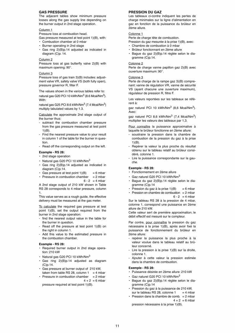
GAS PRESSUREThe adjacent tables show minimum pressurelosses along the gas supply line depending onthe burner output in 2nd stage operation.
Column 1Pressure loss at combustion head.Gas pressure measured at test point 1)(B), with:¥ Combustion chamber at 0 mbar¥ Burner operating in 2nd stage¥ Gas ring 2)(B)p.14 adjusted as indicated in
diagram (C)p. 14.
Column 2Pressure loss at gas butterßy valve 2)(B) withmaximum opening: 90°.
Column 3Pressure loss of gas train 3)(B) includes: adjust-ment valve VR, safety valve VS (both fully open),pressure governor R, Þlter F.
The values shown in the various tables refer to:
natural gas G20 PCI 10 kWh/Nm3 (8.6 Mcal/Nm3).With:
natural gas G25 PCI 8.6 kWh/Nm3 (7.4 Mcal/Nm3)multiply tabulated values by 1.3.
Calculate the approximate 2nd stage output ofthe burner thus:- subtract the combustion chamber pressure
from the gas pressure measured at test point1)(B).
- Find the nearest pressure value to your resultin column 1 of the table for the burner in ques-tion.
- Read off the corresponding output on the left.
Example - RS 28:¥ 2nd stage operation
¥ Natural gas G20 PCI 10 kWh/Nm3
¥ Gas ring 2)(B)p.14 adjusted as indicated indiagram (C)p.14.
¥ Gas pressure at test point 1)(B) = 6 mbar¥ Pressure in combustion chamber = 2 mbar
6 - 2 = 4 mbarA 2nd stage output of 210 kW shown in TableRS 28 corresponds to 4 mbar pressure, column1. This value serves as a rough guide, the effectivedelivery must be measured at the gas meter.
To calculate the required gas pressure at testpoint 1)(B), set the output required from theburner in 2nd stage operation:- Þnd the nearest output value in the table for
the burner in question.- Read off the pressure at test point 1)(B) on
the right in column 1.- Add this value to the estimated pressure in
the combustion chamber.
Example - RS 28:¥ Required burner output in 2nd stage opera-
tion: 210 kW
¥ Natural gas G20 PCI 10 kWh/Nm3
¥ Gas ring 2)(B)p.14 adjusted as diagram(C)p.14.
¥ Gas pressure at burner output of 210 kW,taken from table RS 28, column 1 = 4 mbar
¥ Pressure in combustion chamber = 2 mbar4 + 2 = 6 mbar
pressure required at test point 1)(B).
PRESSION DU GAZLes tableaux ci-contre indiquent les pertes decharge minimales sur la ligne d'alimentation engaz en fonction de la puissance du br�leur en2�me allure.
Colonne 1Perte de charge t�te de combustion.Pression du gaz mesur�e � la prise 1)(B), avec:¥ Chambre de combustion � 0 mbar¥ Br�leur fonctionnant en 2�me allure¥ Bague du gaz 2)(B)p.14 r�gl�e selon le dia-
gramme (C)p.14.
Colonne 2Perte de charge vanne papillon gaz 2)(B) avecouverture maximum: 90°.
Colonne 3Perte de charge de la rampe gaz 3)(B) compre-nant: vanne de r�gulation VR, vanne de s�curit�VS (ayant chacune une ouverture maximum),r�gulateur de pression R, Þltre F.
Les valeurs report�es sur les tableaux se r�f�-rent �:
gaz naturel PCI 10 kWh/Nm3 (8,6 Mcal/Nm3).Avec:
gaz naturel PCI 8,6 kWh/Nm3 (7,4 Mcal/Nm3)multiplier les valeurs des tableaux par 1,3.
Pour conna�tre la puissance approximative �laquelle le br�leur fonctionne en 2�me allure:- soustraire la pression dans la chambre de
combustion de la pression du gaz � la prise1)(B).
- Rep�rer la valeur la plus proche du r�sultatobtenu sur le tableau relatif au br�leur consi-d�r�, colonne 1.
- Lire la puissance correspondante sur la gau-che.
Exemple - RS 28:¥ Fonctionnement en 2�me allure
¥ Gaz naturel G20 PCI 10 kWh/Nm3
¥ Bague du gaz 2)(B)p.14 r�gl�e selon le dia-gramme (C)p.14
¥ Pression du gaz � la prise 1)(B) = 6 mbar¥ Pression en chambre de combustion = 2 mbar
6 - 2 = 4 mbarSur le tableau RS 28 � la pression de 4 mbar,colonne 1, correspond une puissance en 2�meallure de 210 kW.Cette valeur sert de premi�re approximation; led�bit effectif est mesur� sur le compteur.
Par contre, pour conna�tre la pression du gazn�cessaire � la prise 1)(B), apr�s avoir Þx� lapuissance de fonctionnement du br�leur en2�me allure:- rep�rer la puissance la plus proche � la
valeur voulue dans le tableau relatif au br�-leur concern�.
- Lire la pression � la prise 1)(B) sur la droite,colonne 1.
- Ajouter � cette valeur la pression estim�edans la chambre de combustion.
Exemple - RS 28:¥ Puissance d�sir�e en 2�me allure: 210 kW
¥ Gaz naturel G20 PCI 10 kWh/Nm3
¥ Bague du gaz 2)(B)p.14 r�gl�e selon le dia-gramme (C)p.14
¥ Pression du gaz � la puissance de 210 kW,sur le tableau RS 28, colonne 1 = 4 mbar
¥ Pression dans la chambre de comb. = 2 mbar4 + 2 = 6 mbar
pression n�cessaire � la prise 1)(B).

12
INSTALLATION
KESSELPLATTE (A)Die Abdeckplatte der Brennkammer wie in (A)gezeigt vorbohren. Die Position der Gewindebohrungen kann mitdem zur Grundausstattung geh�renden W�rme-schild ermittelt werden.
FLAMMROHRL�NGE (B)Die L�nge des Flammrohrs wird entsprechendder Angaben des Kesselherstellers gew�hlt undmu§ in jedem Fall gr�§er als die St�rke der Kes-selt�r einschlie§lich feuerfestes Material sein.Die verf�gbaren L�ngen, L (mm), sind:
Flammrohr 10): RS 28 RS 38 RS 50¥ kurz 216 216 216¥ lang 351 351 351
F�r Heizkessel mit vorderem Abgasumlauf 13)oder mit Flammenumkehrkammer mu§ eineSchutzschicht aus feuerfestem Material 11),zwischen feuerfestem Material des Kessels 12)und Flammrohr 10) ausgef�ht werden.Diese Schutzschicht mu§ so angelegt sein, da§das Flammrohr ausbaubar ist. F�r die Kessel mit wassergek�hlter Frontseiteist die Verkleidung mit feuerfestem Material 11)-12)(B) nicht notwendig, sofern nicht ausdr�ck-lich vom Kesselhersteller erfordert.
BEFESTIGUNG DES BRENNERS AM HEIZ-KESSEL (B)Vor der Befestigung des Brenners am Heizkes-sel ist von der �ffnung des Flammrohrs aus zu�berpr�fen, ob der F�hler und die Elektrodegem�§ (C) in der richtigen Stellung sind.
Dann den Flammkopf vom �brigen Brennerabtrennen, Abb.(B):- Schrauben 14) abnehmen und die Verklei-
dung 15) herausziehen.- Das Gelenk 4) des Skalensegments 5) ausrasten.- Die Schrauben 2) von den zwei Gleitschienen
3) abnehmen.- Die Schraube 1) abnehmen und den Brenner
auf den Gleitschienen 3) ca. 100 mm nachhinten schieben. Die F�hler- und Elektrodenkabel abtrennenund dann den Brenner komplett aus denGleitschienen ziehen, nach Entnahme desSplints aus der F�hrung 3).
Den Flansch 9)(B) an der Kesselplatte befesti-gen und den beigestellten W�rmeschild 6)(B)dazwischenlegen. Die 4 ebenfalls beigepacktenSchrauben nach Auftragung von Fre§schutzmit-teln verwenden. Es mu§ die Dichtheit von Brenner-Kesselgew�hrleistet sein.
Falls bei der vorhergehenden Pr�fung die Posi-tionierung des F�hlers oder der Elektrode sichals nicht richtig erweist, die Schraube 1)(D)abnehmen, das Innenteil 2)(D) des Kopfs her-ausziehen und eine neue Einstellung vorneh-men. Den F�hler nicht drehen, sondern wie in(C) lassen; seine Positionierung in der N�he derZ�ndelektrode k�nnte den Ger�teverst�rkerbesch�digen.
(A)
(B)
mm A B C
RS 28 160 224 M 8
RS 38 160 224 M 8
RS 50 160 224 M 8
(C)
(D)
F�hlerProbeSonde
Elektrode RS 28-38Electrode RS 28-38Electrode RS 28-38
Elektrode RS 50Electrode RS 50Electrode RS 50

13
INSTALLATION
BOILER PLATE (A)Drill the combustion chamber locking plate asshown in (A). The position of the threaded holes can bemarked using the thermal screen supplied withthe burner.
BLAST TUBE LENGTH (B)The length of the blast tube must be selectedaccording to the indications provided by themanufacturer of the boiler, and in any case itmust be greater than the thickness of the boilerdoor complete with its fettling. The range oflengths available, L (mm), is as follows:
Blast tube 10): RS 28 RS 38 RS 50¥ short 216 216 216¥ long 351 351 351
For boilers with front ßue passes 13) or ßameinversion chambers, protective fettling in refrac-tory material 11) must be inserted between theboiler fettling 12) and the blast tube 10). This protective fettling must not compromise theextraction of the blast tube.For boilers having a water-cooled front therefractory fettling 11)-12)(B) is not requiredunless it is expressly requested by the boilermanufacturer.
SECURING THE BURNER TO THE BOILER (B)Before securing the burner to the boiler, checkthrough the blast tube opening to make surethat the ßame sensor probe and the ignitionelectrode are correctly set in position, as shownin (C).
Now detach the combustion head from theburner, Þg.(B):- remove screw 14) and withdraw the cover
15).- Disengage the articulated coupling 4) from
the graduated sector 5).- Remove the screws 2) from the slide bars 3)- Remove screw 1) and pull the burner back on
slide bars 3) by about 100 mm.Disconnect the wires from the probe and theelectrode and then pull the burner completelyoff the slide bars, after removing the split pinfrom the slide bar 3).
Secure the ßange 9)(B) to the boiler plate, inter-posing the thermal insulating screen 6)(B) sup-plied with the burner. Use the 4 screws, alsosupplied with the unit, after Þrst protecting thethread with an anti-locking product.The seal between burner and boiler must be air-tight.
If you noticed any irregularities in positions ofthe probe or ignition electrode during the checkmentioned above, remove screw 1)(D), extractthe internal part 2)(D) of the head and proceedto set up the two components correctly. Do not attempt to turn the probe. Leave it in theposition shown in (C) since if it is located tooclose to the ignition electrode the control boxampliÞer may be damaged.
INSTALLATION
PLAQUE CHAUDIERE (A)Percer la plaque de fermeture de la chambre decombustion comme sur la Þg.(A). La position des trous Þlet�s peut �tre trac�e enutilisant l'�cran thermique fourni avec le br�leur.
LONGUEUR BUSE (B)La longueur de la buse doit �tre choisie selonles indications du constructeur de la chaudi�re,en tous cas, elle doit �tre sup�rieure � l'�pais-seur de la porte de la chaudi�re, mat�riaur�fractaire compris. Les longueurs, L (mm), dis-ponibles sont:
Buse 10): RS 28 RS 38 RS 50¥ courte 216 216 216¥ longue 351 351 351
Pour les chaudi�res avec circulation des fum�essur l'avant 13), ou avec chambre � inversion deßamme, r�aliser une protection en mat�riaur�fractaire 11), entre r�fractaire chaudi�re 12) etbuse 10). La protection doit permettre l'extraction de labuse.Pour les chaudi�res dont la partie frontale estrefroidie par eau, le rev�tement r�fractaire 11)-12)(B) n'est pas n�cessaire, sauf indication pr�-cise du constructeur de la chaudi�re.
FIXATION DU BRULEUR A LA CHAUDIERE (B)Avant de Þxer le br�leur � la chaudi�re, v�riÞerpar l'ouverture de la buse si la sonde et l'�lec-trode sont positionn�es correctement commeindiqu� en (C).
S�parer ensuite la t�te de combustion du restedu br�leur, Þg.(B):- retirer la vis 14) et extraire le coffret 15).- D�crocher la rotule 4) du secteur gradu� 5).- Retirer les vis 2) des deux guides 3).- Retirer les vis 1) et faire reculer le br�leur sur
les guides 3) d'environ 100 mm.D�tacher les c�bles de la sonde et de l'�lec-trode, enlever ensuite compl�tement le br�-leur des guides, apr�s avoir �t� la goupille dela guide 3).
Fixer la bride 9)(B) � la plaque de la chaudi�reen interposant l'�cran isolant 6)(B) fourni des�rie. Utiliser les 4 vis �galement de s�rie apr�sen avoir prot�g� le Þletage par du produit anti-grippant.L'�tanch�it� br�leur-chaudi�re doit �tre parfaite.
Si, lors du contr�le pr�c�dent, le positionne-ment de la sonde ou de l'�lectrode n'�tait pascorrect, retirer la vis 1)(D), extraire la partieinterne 2)(D) de la t�te et tarer celles-ci. Ne pas faire pivoter la sonde mais la laisser enplace comme indiqu� en (C); son positionne-ment dans le voisinage de l'�lectrode d'allu-mage pourrait endommager l'ampliÞcateur del'appareil.
14
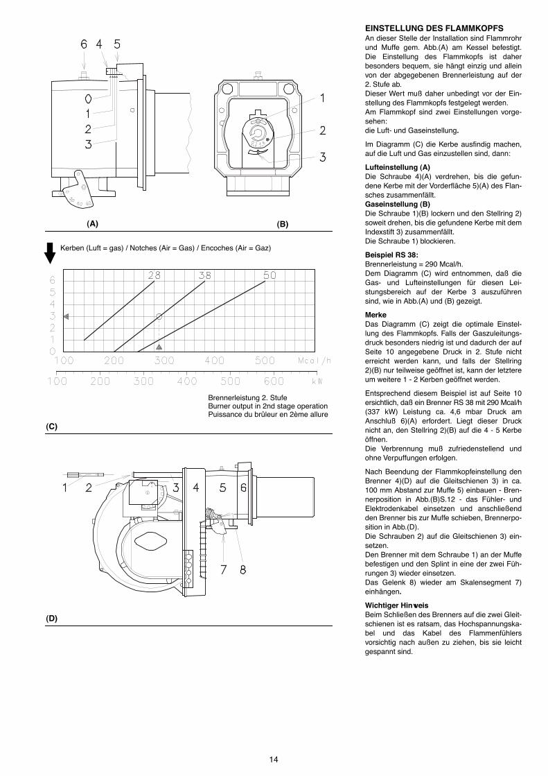
EINSTELLUNG DES FLAMMKOPFSAn dieser Stelle der Installation sind Flammrohrund Muffe gem. Abb.(A) am Kessel befestigt.Die Einstellung des Flammkopfs ist daherbesonders bequem, sie h�ngt einzig und alleinvon der abgegebenen Brennerleistung auf der2. Stufe ab. Dieser Wert mu§ daher unbedingt vor der Ein-stellung des Flammkopfs festgelegt werden. Am Flammkopf sind zwei Einstellungen vorge-sehen: die Luft- und Gaseinstellung.
Im Diagramm (C) die Kerbe ausÞndig machen,auf die Luft und Gas einzustellen sind, dann:
Lufteinstellung (A)Die Schraube 4)(A) verdrehen, bis die gefun-dene Kerbe mit der Vorder�che 5)(A) des Flan-sches zusammenf�llt.Gaseinstellung (B)Die Schraube 1)(B) lockern und den Stellring 2)soweit drehen, bis die gefundene Kerbe mit demIndexstift 3) zusammenf�llt. Die Schraube 1) blockieren.
Beispiel RS 38:Brennerleistung = 290 Mcal/h. Dem Diagramm (C) wird entnommen, da§ dieGas- und Lufteinstellungen f�r diesen Lei-stungsbereich auf der Kerbe 3 auszuf�hrensind, wie in Abb.(A) und (B) gezeigt.
MerkeDas Diagramm (C) zeigt die optimale Einstel-lung des Flammkopfs. Falls der Gaszuleitungs-druck besonders niedrig ist und dadurch der aufSeite 10 angegebene Druck in 2. Stufe nichterreicht werden kann, und falls der Stellring2)(B) nur teilweise ge�ffnet ist, kann der letztereum weitere 1 - 2 Kerben ge�ffnet werden.
Entsprechend diesem Beispiel ist auf Seite 10ersichtlich, da§ ein Brenner RS 38 mit 290 Mcal/h(337 kW) Leistung ca. 4,6 mbar Druck amAnschlu§ 6)(A) erfordert. Liegt dieser Drucknicht an, den Stellring 2)(B) auf die 4 - 5 Kerbe�ffnen. Die Verbrennung mu§ zufriedenstellend undohne Verpuffungen erfolgen.
Nach Beendung der Flammkopfeinstellung denBrenner 4)(D) auf die Gleitschienen 3) in ca.100 mm Abstand zur Muffe 5) einbauen - Bren-nerposition in Abb.(B)S.12 - das F�hler- undElektrodenkabel einsetzen und anschlie§endden Brenner bis zur Muffe schieben, Brennerpo-sition in Abb.(D). Die Schrauben 2) auf die Gleitschienen 3) ein-setzen. Den Brenner mit dem Schraube 1) an der Muffebefestigen und den Splint in eine der zwei F�h-rungen 3) wieder einsetzen. Das Gelenk 8) wieder am Skalensegment 7)einh�ngen.
Wichtiger HinweisBeim Schlie§en des Brenners auf die zwei Gleit-schienen ist es ratsam, das Hochspannungska-bel und das Kabel des Flammenf�hlersvorsichtig nach au§en zu ziehen, bis sie leichtgespannt sind.
(A)
(C)
(B)
(D)
Kerben (Luft = gas) / Notches (Air = Gas) / Encoches (Air = Gaz)
Brennerleistung 2. StufeBurner output in 2nd stage operationPuissance du br�leur en 2�me allure

15
SETTING THE COMBUSTION HEADInstallation operations are now at the stagewhere the blast tube and sleeve are secured tothe boiler as shown in Þg.(A). It is now a verysimple matter to set up the combustion head, asthis depends solely on the output developed bythe burner in 2nd stage operation. It is therefore essential to establish this valuebefore proceeding to set up the combustionhead. There are two adjustments to make on thehead: air and gas deliveries.
In diagram (C) Þnd the notch to use for adjustingthe air and the gas, and then proceed as fol-lows:
Air adjustment (A)Turn screw 4)(A) until the notch identiÞed isaligned with the front surface 5)(A) of the ßange.Gas adjustment (B)Loosen screws 1)(B) and turn ring 2) until thenotch identiÞed is aligned with index 3). Tighten the screw 1) fully down.
Example RS 38:burner output = 290 Mcal/h.If we consult diagram (C) we Þnd that for thisoutput, air and gas must be adjusted usingnotch 3, as shown in Þgs.(A) and (B).
NoteDiagram (C) shows the ideal settings for thecombustion head. If the gas mains pressure istoo low to reach the 2nd stage operation pres-sure indicated on page 10, and if the ring 2)(B)is not fully open, it can be opened wider by 1 or2 notches.
Continuing with the previous example, page 10indicates that for burner RS 38 with output of290 Mcal/h (337 kW) a pressure of approxi-mately 4,6 mbar is necessary at test point 6)(A).If this pressure cannot be reached, open thering 2)(B) to notch 4 or 5. Make sure that the combustion characteristicsare satisfactory and free of pulsations.
Once you have Þnished setting up the head, reÞtthe burner 4)(D) to the slide bars 3) at approxi-mately 100 mm from the sleeve 5) - burner posi-tioned as shown in Þg.(B)p.12 - insert the ßamedetection probe cable and the ignition electrodecable and then slide the burner up to the sleeveso that it is positioned as shown in Þg.(D). ReÞt screws 2) on slide bars 3). Secure the burner to the sleeve by tighteningscrew 1) and then reÞt the split pin into one oftwo slide bars 3). Reconnect the articulation 8) to the graduatedsector 7).
ImportantWhen Þtting the burner on the two slide bars, itis advisable to gently draw out the high tensioncable and ßame detection probe cable until theyare slightly stretched.
REGLAGE TETE DE COMBUSTIONA ce stade de l'installation, buse et manchonsont Þx�s � la chaudi�re comme indiqu� sur laÞg.(A). Le r�glage de la t�te de combustion estdonc particuli�rement facile, et d�pend unique-ment de la puissance d�velopp�e par le br�leuren 2�me allure.C'est pourquoi, il faut Þxer cette valeur avant der�gler la t�te de combustion.Deux r�glages de la t�te sont pr�vus:le r�glage de l'air et celui du gaz.
Trouver sur le diagramme (C) l'encoche surlaquelle r�gler l'air et le gaz.
R�glage de l'air (A)Faire pivoter la vis 4)(A) jusqu'� faire correspon-dre l'encoche trouv�e avec le plan ant�rieur5)(A) de la bride.R�glage du gaz (B)Desserrer la vis 1)(B) et faire tourner la bague2) jusqu'� faire correspondre l'encoche avec lerep�re 3).Bloquer la vis 1).
Exemple RS 38:puissance du br�leur = 290 Mcal/h. Le diagramme (C) indique que pour cette puis-sance les r�glages du gaz et de l'air seronteffectu�s sur l'encoche 3, comme indiqu� sur laÞg.(A) et (B).
NoteLe diagramme (C) indique le r�glage optimal dela t�te. Si la pression du r�seau d'alimentationen gaz est tr�s faible et ne permet pas d'attein-dre la pression indiqu�e page 10 en 2�meallure, et si la bague 2)(B) n'est ouverte qu'enpartie, il est possible d'ouvrir encore cettebague de 1 ou 2 encoches.
Pour continuer l'exemple pr�c�dent, la page 10indique que pour un br�leur RS 38 de puis-sance 290 Mcal/h (337 kW) il faut 4,6 mbar envi-ron de pression � la prise 6)(A). Si cettepression n'est pas disponible, ouvrir la bague2)(B) de 4 ou 5 encoches. Contr�ler que la combustion soit satisfaisante etsans saccades.
Une fois termin� le r�glage de la t�te, remonterle br�leur 4)(D) sur les guides 3) � environ 100mm du manchon 5) - br�leur dans la positionillustr�e Þg.(B)p.12 - ins�rer les c�bles de lasonde et de l'�lectrode et ensuite faire coulisserle br�leur jusqu'au manchon, br�leur dans laposition illustr�e Þg.(D). Replacer les vis 2) sur les guides 3). Fixer le br�leur au manchon avec la vis 1) etreplacer la goupille dans une des deux guides3). Raccrocher la rotule 8) au secteur gradu� 7).
AttentionAu moment de la fermeture du br�leur sur lesdeux guides, il faut tirer d�licatement vers l'ext�-rieur le c�ble de haute tension et le petit c�blede la sonde de d�tection ßamme, jusqu'� cequ'ils soient l�g�rement tendus.
16
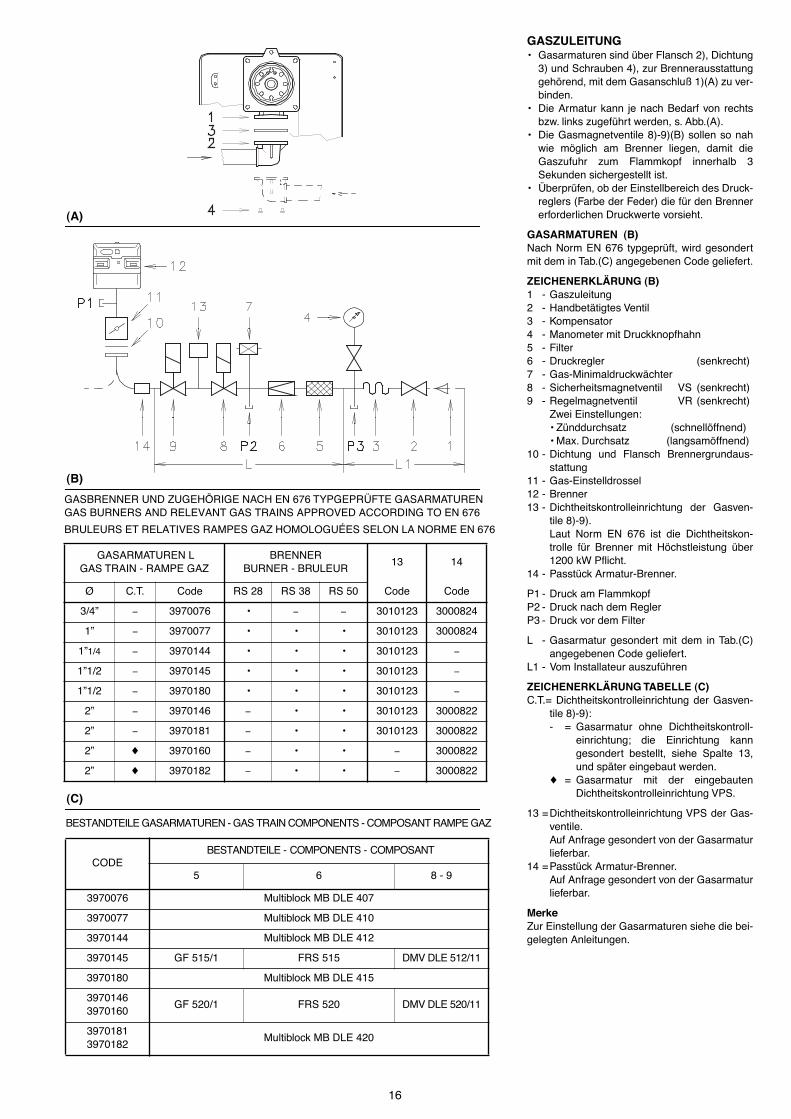
GASZULEITUNG¥ Gasarmaturen sind �ber Flansch 2), Dichtung
3) und Schrauben 4), zur Brennerausstattunggeh�rend, mit dem Gasanschlu§ 1)(A) zu ver-binden.
¥ Die Armatur kann je nach Bedarf von rechtsbzw. links zugef�hrt werden, s. Abb.(A).
¥ Die Gasmagnetventile 8)-9)(B) sollen so nahwie m�glich am Brenner liegen, damit dieGaszufuhr zum Flammkopf innerhalb 3Sekunden sichergestellt ist.
¥ �berpr�fen, ob der Einstellbereich des Druck-reglers (Farbe der Feder) die f�r den Brennererforderlichen Druckwerte vorsieht.
GASARMATUREN (B)Nach Norm EN 676 typgepr�ft, wird gesondertmit dem in Tab.(C) angegebenen Code geliefert.
ZEICHENERKL�RUNG (B)1 - Gaszuleitung2 - Handbet�tigtes Ventil3 - Kompensator4 - Manometer mit Druckknopfhahn5 - Filter6 - Druckregler (senkrecht)7 - Gas-Minimaldruckw�chter8 - Sicherheitsmagnetventil VS (senkrecht)9 - Regelmagnetventil VR (senkrecht)
Zwei Einstellungen:¥ Z�nddurchsatz (schnell�ffnend)¥ Max. Durchsatz (langsam�ffnend)
10 - Dichtung und Flansch Brennergrundaus-stattung
11 - Gas-Einstelldrossel12 - Brenner13 - Dichtheitskontrolleinrichtung der Gasven-
tile 8)-9). Laut Norm EN 676 ist die Dichtheitskon-trolle f�r Brenner mit H�chstleistung �ber1200 kW Pßicht.
14 - Passt�ck Armatur-Brenner.
P1 - Druck am FlammkopfP2 - Druck nach dem ReglerP3 - Druck vor dem Filter
L - Gasarmatur gesondert mit dem in Tab.(C)angegebenen Code geliefert.
L1 - Vom Installateur auszuf�hren
ZEICHENERKL�RUNG TABELLE (C)C.T.= Dichtheitskontrolleinrichtung der Gasven-
tile 8)-9):- = Gasarmatur ohne Dichtheitskontroll-
einrichtung; die Einrichtung kanngesondert bestellt, siehe Spalte 13,und sp�ter eingebaut werden.
¨ = Gasarmatur mit der eingebautenDichtheitskontrolleinrichtung VPS.
13 =Dichtheitskontrolleinrichtung VPS der Gas-ventile. Auf Anfrage gesondert von der Gasarmaturlieferbar.
14 =Passt�ck Armatur-Brenner. Auf Anfrage gesondert von der Gasarmaturlieferbar.
Merke Zur Einstellung der Gasarmaturen siehe die bei-gelegten Anleitungen.
(A)
(B)
(C)
GASBRENNER UND ZUGEH�RIGE NACH EN 676 TYPGEPR�FTE GASARMATURENGAS BURNERS AND RELEVANT GAS TRAINS APPROVED ACCORDING TO EN 676
BRULEURS ET RELATIVES RAMPES GAZ HOMOLOGU�ES SELON LA NORME EN 676
GASARMATUREN LGAS TRAIN - RAMPE GAZ
BRENNERBURNER - BRULEUR
13 14
¯ C.T. Code RS 28 RS 38 RS 50 Code Code
3/4Ó - 3970076 ¥ - - 3010123 3000824
1Ó - 3970077 ¥ ¥ ¥ 3010123 3000824
1Ó1/4 - 3970144 ¥ ¥ ¥ 3010123 -
1Ó1/2 - 3970145 ¥ ¥ ¥ 3010123 -
1Ó1/2 - 3970180 ¥ ¥ ¥ 3010123 -
2Ó - 3970146 - ¥ ¥ 3010123 3000822
2Ó - 3970181 - ¥ ¥ 3010123 3000822
2Ó ¨ 3970160 - ¥ ¥ - 3000822
2Ó ¨ 3970182 - ¥ ¥ - 3000822
BESTANDTEILE GASARMATUREN - GAS TRAIN COMPONENTS - COMPOSANT RAMPE GAZ
CODE BESTANDTEILE - COMPONENTS - COMPOSANT
5 6 8 - 9
3970076 Multiblock MB DLE 407
3970077 Multiblock MB DLE 410
3970144 Multiblock MB DLE 412
3970145 GF 515/1 FRS 515 DMV DLE 512/11
3970180 Multiblock MB DLE 415
39701463970160
GF 520/1 FRS 520 DMV DLE 520/11
39701813970182
Multiblock MB DLE 420
17
GAS LINE¥ The gas train must be connected to the gas
attachment 1)(A), using ßange 2), gasket 3)and screws 4) supplied with the burner.
¥ The gas train can enter the burner from theright or left side, depending on which is themost convenient, see Þg.(A).
¥ Gas solenoids 8)-9)(B) must be as close aspossible to the burner to ensure gas reachesthe combustion head within the safety timerange of 3 s.
¥ Make sure that the pressure governor calibra-tion range (colour of the spring) comprisesthe pressure required by the burner.
GAS TRAIN (B)It is type-approved according to EN 676 Stan-dards and is supplied separately from theburner with the code indicated in Table (C).
KEY (B)1 - Gas input pipe2 - Manual valve3 - Vibration damping joint4 - Pressure gauge with pushbutton cock5 - Filter6 - Pressure governor (vertical)7 - Minimum gas pressure switch8 - Safety solenoid VS (vertical)9 - Adjustment solenoid VR (vertical)
Two adjustments:¥ ignition delivery (rapid opening)¥ maximum delivery (slow opening)
10 - Standard issue burner gasket with ßange11 - Gas adjustment butterßy valve12 - Burner13 - Gas valve 8)-9) leak detection control
device. In accordance with EN 676 Standards, gasvalve leak detection control devices arecompulsory for burners with maximum out-puts of more than 1200 kW.
14 - Gas train/burner adaptor.
P1 - Pressure at combustion head P2 - Pressure down-line from the pressure gov-
ernor P3 - Pressure up-line from the Þlter
L - Gas train supplied separately with the codeindicated in Table (C)
L1 - The responsibility of the installer
KEY TO TABLE (C)C.T. =Gas valves 8) - 9) leak detection control
devices:- = Gas train without gas valve leak detec-
tion control device; device that can beordered separately and assembled sub-sequently (see Column 13).
¨= Gas train with assembled VPS valveleak detection control device.
13 =VPS valve leak detection control device.Supplied separately from gas train onrequest.
14 =Gas train/burner adaptor. Supplied separately from gas train onrequest.
NoteSee the accompanying instructions for theadjustment of the gas train.
LIGNE ALIMENTATION GAZ- La rampe du gaz doit �tre reli�e au raccord
du gaz 1)(A), par la bride 2), le joint 3) et lesvis 4) fournis de s�rie avec le br�leur.
- La rampe peut arriver par la droite ou par lagauche selon les cas, comme indiqu� sur laÞg.(A).
- Les �lectrovannes 8)-9)(B) du gaz doivent�tre le plus pr�s possible du br�leur de fa�on� assurer l'arriv�e du gaz � la t�te de com-bustion en un temps de s�curit� de 3 s.
- Contr�ler que la plage de r�glage du r�gula-teur de pression (couleur du ressort) recouvrela pression n�cessaire au br�leur.
RAMPE GAZ (B)Elle est homologu�e suivant la norme EN 676 etelle est fournie s�par�ment du br�leur avec lecode indiqu� dans le tableau (C).
LEGENDA (B)1 - Canalisation d'arriv�e du gaz2 - Vanne manuelle3 - Joint anti-vibrations4 - Manom�tre avec robinet � bouton poussoir5 - Filtre6 - R�gulateur de pression (vertical)7 - Pressostat gaz de seuil minimum8 - Electrovanne de s�curit� VS (verticale)9 - Electrovanne de r�gulation VR (verticale)
Deux r�glages:¥ d�bit d'allumage (ouverture rapide)¥ d�bit maximum (ouverture lente)
10 - Joint et bride fournis avec le br�leur11 - Papillon r�glage gaz12 - Br�leur 13 - Dispositif de contr�le d'�tanch�it� vannes
8)-9)Selon la norme EN 676, le contr�le d'�tan-ch�it� est obligatoire pour les br�leursayant une puissance maximale sup�rieure� 1200 kW.
14 - Adaptateur rampe-br�leur.
P1 - Pression � la t�te de combustionP2 - Pression en aval du r�gulateurP3 - Pression en amont du Þltre
L - La rampe gaz est fournie � part avec lecode indiqu� dans le tab.(C).
L1 - A la charge de l'installateur
LEGENDE TABLEAU (C)C.T. =Dispositif de contr�le d'�tanch�it� vannes
8)-9):- =Rampe sans dispositif de contr�le
d'�tanch�it�; dispositif qui peut �trecommand� � part et mont� par lasuite, voir colonne 13.
¨=Rampe avec dispositif de contr�led'�tanch�it� VPS mont�.
13 =Dispositif VPS de contr�le d'�tanch�it�de la vanne.Fourni sur demande s�par�ment de larampe gaz.
14 =Adaptateur rampe-br�leur.Fourni sur demande s�par�ment de larampe gaz.
NotePour le r�glage de la rampe gaz voir les instruc-tions qui l'accompagnent.

18
ELEKTROANLAGE
ELEKTROANLAGE werkseitig ausgef�hrt
SCHEMA (A)Brenner RS 28 (einphasing)
SCHEMA (B)Brenner RS 38 (einphasing)
SCHEMA (C)Brenner RS 38 - 50 (dreiphasing)
¥ Die Modelle RS 38 und RS 50 dreiphasingwerden werkseitig f�r 400 V Stromversorgungvorbereitet.
¥ Falls die Stromversorgung 230 V betr�gt, denMotoranschlu§ (von Stern- auf Dreieckschal-tung) und die Einstellung des �berstromaus-l�sers ver�ndern.
Zeichenerkl�rung Schemen (A) - (B) - (C)C - KondensatorCMV - MotorkontaktgeberF1 - Funkentst�rerMMI 813 - Steuerger�tI1 - Schalter: Brenner "ein - aus"I2 - Schalter: "1. - 2. Stufe"MV - Gebl�semotorPA - Luftdruckw�chterRT - �berstromausl�serSM - StellantriebSO - IonisationssondeSP - Steckanschlu§TA - Z�ndtransformatorTB - BrennererdungXP4 - Steckerbuchse mit 4 PolenXP5 - Steckerbuchse mit 5 PolenXP6 - Steckerbuchse mit 6 PolenXP7 - Steckerbuchse mit 7 PolenU - STATUS bzw. LED PANEL.
Der Draht an Klemme 6 ist nur beiSTATUS vorhanden.
(A)
(B)
(C)
RS 28 Einphasing / Single-phase / Monophas�WERKSEITIG AUSGEF�HRTE ELEKTROANLAGEELECTRICAL EQUIPMENT FACTORY-SETINSTALLATION ELECTRIQUE REALISEE EN USINE
RS 38 Einphasing / Single-phase / Monophas�WERKSEITIG AUSGEF�HRTE ELEKTROANLAGEELECTRICAL EQUIPMENT FACTORY-SETINSTALLATION ELECTRIQUE REALISEE EN USINE
RS 38 - RS 50 Dreiphasing / Triple-phase/ Triphas�WERKSEITIG AUSGEF�HRTE ELEKTROANLAGEELECTRICAL EQUIPMENT FACTORY-SETINSTALLATION ELECTRIQUE REALISEE EN USINE

19
ELECTRICAL SYSTEM
ELECTRICAL SYSTEM as set up by the manu-facturer
LAYOUT (A)Burner RS 28 (single-phase)
LAYOUT (B)Burner RS 38 (single-phase)
LAYOUT (C)Burners RS 38 - 50 (three-phase)
¥ Models RS 38 and RS 50 leave the factorypreset for 400 V power supply.
¥ If 230 V power supply is used, change themotor connection from star to delta andchange the setting of the thermal cut-out aswell.
Key to Layouts (A) - (B) - (C)C - CapacitorCMV - Motor contactorF1 - Protection against radio interferenceMMI 813 - Control boxI1 - Switch: burner off - onI2 - Switch: 1st - 2nd stage operationMV - Fan motorPA - Air pressure switchRT - Thermal cut-outSM - ServomotorSO - Ionisation probeSP - Plug-socketTA - Ignition transformerTB - Burner groundXP4 - 4 pole socketXP5 - 5 pole socketXP6 - 6 pole socketXP7 - 7 pole socketU - STATUS unit or LED PANEL.
The wire to terminal 6 is installedonly when the burner is equippedwith a STATUS unit.
INSTALLATION ELECTRIQUE
INSTALLATION ELECTRIQUE r�alis�e enusine
SCHEMA (A)Br�leur RS 28 (monophas�)
SCHEMA (B)Br�leur RS 38 (monophas�)
SCHEMA (C)Br�leurs RS 38 - 50 (triphas�s)
¥ Les mod�les RS 38 et RS 50 triphas�s quit-tent l'usine pr�vus pour une alimentation�lectrique � 400 V.
¥ Si l'alimentation est � 230 V, modiÞer le bran-chement du moteur (d'�toile � triangle) et ler�glage du relais thermique.
L�gende sch�mas (A) - (B) - (C)C - CondensateurCMV - Contacteur moteurF1 - Protection contre parasites radioMMI 813 - Coffret de s�curit�I1 - Interrupteur: br�leur allum� - �teintI2 - Interrupteur: 1�re - 2�me allureMV - Moteur ventilateurPA - Pressostat airRT - Relais thermiqueSM - ServomoteurSO - Sonde d'ionisationSP - Fiche-priseTA - Transformateur d'allumageTB - Mise � la terre br�leurXP4 - Prise 4 p�lesXP5 - Prise 5 p�lesXP6 - Prise 6 p�lesXP7 - Prise 7 p�lesU - STATUS ou LED PANEL.
Le Þl � la borne 6 n'est pr�sentqu'avec STATUS.

20
ELEKTROANSCHL�SSEGem�§ Norm EN 60 335-1 biegsame Kabel ver-wenden:¥ falls unter PVC-Mantel mindestens den Typ
H05 VV-F verwenden.¥ falls unter Gummimantel mindestens den Typ
H05 RR-F verwenden.Alle an die Stecken 7)(A) anzuschlie§endenKabel sind durch die beigepackten Kabeldurch-g�nge zu f�hren, die nach Abdrehen derSchrauben 8), �ffnen der Plattenteile 9) und 10)und Abnahme der Verschlu§blende in die Boh-rungen der rechten oder linken Platte einge-steckt werden.Die Kabeldurchg�nge und Vorbohrungen k�n-nen auf verschiedene Art verwendet werden;hier folgend ein Beispiel:
RS 28 und RS 38 einphasing 1 - Pg 11 Einphasenspeisung2 - Pg 11 Gasventile
(wenn die Dichtheitskontrolleinrich-tung RG1/CT oder LDU 11 nichteingebaut ist)
3 - Pg 9 TL-Regelung4 - Pg 9 TR-Regelung5 - Pg 11 Gasdruckw�chter oder Dichtheits-
kontrolle der Gasventile
RS 38 dreiphasing und RS 501 - Pg 11 Dreiphasenspeisung2 - Pg 11 Einphasenspeisung3 - Pg 9 TL-Regler4 - Pg 9 TR-Regler5 - Pg 11 Gasventile
(wenn die Dichtheitskontrolleinrich-tung RG1/CT oder LDU 11 nichteingebaut ist)
6 - Pg 11 Gasdruckw�chter oder Dichtheits-kontrolle der Gasventile
SCHEMA (B) - EinphasenspeisungElektroanschlu§ der Brenner RS 28 - 38 ohne Dichtheitskontrolle der Gasventile
SCHEMA (C) - EinphasenspeisungElektroanschlu§ der Brenner RS 28 - 38 mit Dichtheitskontrolle VPS der Gasventile.Die Dichtheitskontrolle der Gasventile erfolgtumgehend vor jedem Brennerstart.
SCHEMA (D) - EinphasenspeisungElektroanschlu§ der Brenner RS 28 - 38 mit Dichtheitskontrolle der Gasventile RG1/CT RIELLO oder LDU 11 LANDIS.Die Dichtheitskontrolle der Gasventile erfolgtumgehend vor jedem Brennerstart.
Zeichenerkl�rung Schemen (B - C - D)h1 - Stundenz�hler der 1 Stufeh2 - Stundenz�hler der 2 StufeIN - Schalter f�r das manuelle Ausschalten des
Brenners XP- Stecker f�r die Dichtheitskontrolleinrichtung X4 - Stecker mit 4 PolenX6 - Stecker mit 6 PolenX7 - Stecker mit 7 PolenPC- Gasdruckw�chter f�r DichtheitskontrollePG- Gas-Mindestdruckw�chter S - St�rabschaltung-Fernmeldung S1 - Fernmeldung St�rabschaltung Dichtheits-
kontrolle TR- Einstell-Fernsteuerung:
steuert 1. und 2. Betriebsstufe. Wird ein Einstufenbetrieb des Brennersgew�nscht, so ist TR zu �berbr�cken.
TL - Begrenzungsfernsteuerung: schaltet den Brenner aus, wenn die Tempe-ratur oder der Kesseldruck den festgeleg-ten H�chstwert erreichen.
TS - Sicherheitsfernsteuerung: tritt bei Defekt an TL in Aktion.
VR- Regelventil VS- Sicherheitsventil
(A)
(B)
(C)
(D)
RS 28 - RS 38 Einphasing / Single-phase / Monophas�
RS 28 - RS 38 Einphasing / Single-phase / Monophas�
RS 28 - RS 38 Einphasing / Single-phase / Monophas�

21
ELECTRICAL CONNECTIONSUse ßexible cables according to EN 60 335-1Regulations:¥ if in PVC sheath, use at least H05 VV-F¥ if in rubber sheath, use at least H05 RR-F.All the wires to connect to the burner plugs 7)(A)must enter through the supplied fairleads, whichmust be Þtted into the relevant holes in the lefthand or right hand plate. To do this, Þrst unscrewscrews 8), then split the plate into its parts 9)and 10) and remove the menbrane press-outsfrom the holes.The fairleads and hole press-outs can be in var-ious ways; the following lists show one possiblesolution:
RS 28 und RS 38 single-phase1 - Pg 11 Single-phase power supply 2 - Pg 11 Gas valves
(when RG1/CT or LDU 11 leakdetection control device is not Þtted)
3 - Pg 9 Remote control device TL4 - Pg 9 Remote control device TR 5 - Pg 11 Gas pressure switch or gas valve
leak detection control device
RS 38 three-phase and RS 501 - Pg 11 Three-phase power supply 2 - Pg 11 Single-phase power supply3 - Pg 9 Remote control device TL4 - Pg 9 Remote control device TR 5 - Pg 11 Gas valves
(when RG1/CT or LDU 11 leakdetection control device is not Þtted)
6 - Pg 11 Gas pressure switch or gas valveleak detection control device
LAYOUT (B) - The RS 28 - 38 Models electricalconnection single-phase power supply without leak detection control device.
LAYOUT (C) The RS 28 - 38 Models electricalconnection single-phase power supply with VPS leak detection control device. Gas valve leak detection control takes placeimmediately before every burner start-up.
LAYOUT (D) The RS 28 - 38 Models electricalconnection single-phase power supplywith RG1/CT RIELLO or LDU LANDIS leakdetection control device. Gas valve leak detection control takes placeimmediately before every burner start-up.
Key to layouts (B - C - D)h1 - 1st stage hourcounterh2 - 2nd stage hourcounterIN - Burner manual stop switchXP- Plug for leak detection control deviceX4 - 4 pole plugX6 - 6 pole plugX7 - 7 pole plugPC- Gas pressure switch for leak detection con-
trol devicePG- Min. gas pressure switchS - Remote lock-out signalS1 - Remote lock-out signal of leak detection
control deviceTR- High-low mode load remote control system:
controls operating stages 1 and 2. If the burner is to be set up for single stageoperation, replace of remote control deviceTR with a jumper.
TL - Load limit remote control system: shuts down the burner when the boiler tem-perature or pressure reaches the presetvalue.
TS - Safety load control system: operates when TL is faulty
VR- Adjustment valveVS- Safety valve
BRANCHEMENTS ELECTRIQUESUtiliser des c�bles ßexibles selon la norme EN60 335-1:¥ si en gaine PVC, au moins type H05 VV-F¥ si en gaine caoutchouc, au moins type H05
RR-F.Tous les c�bles � raccorder aux Þches 7)(A) dubr�leur doivent par les passe-c�bles de s�rie �ins�rer dans les oriÞces pratiqu�s dans la pla-que, de gauche ou de droite, apr�s avoir des-serr� les vis 8), ouvert la plaque (parties 9 et10) et retir� le Þn diephragme recouvrant lestrous. L'utilisation des passe-c�bles et des trouspr�d�coup�s peut se faire de plusieurs fa�ons;� titre d'exemple nous indiquons l'une de cespossibilit�s:
RS 28 et RS 38 monophas�s1 - Pg 11 Alimentation monophas�e2 - Pg 11 Vannes gaz
(lorsque le contr�le d'�tanch�it�RG1/CT ou LDU 11 n'est pas mont�)
3 - Pg 9 T�l�commande TL4 - Pg 9 T�l�commande TR5 - Pg 11 Pressostat gaz ou contr�le d'�tan-
ch�it� vannes gaz
RS 38 triphas� et RS 501 - Pg 11 Alimentation triphas�e2 - Pg 11 Alimentation monophas�e3 - Pg 9 T�l�commande TL4 - Pg 9 T�l�commande TR5 - Pg 11 Vannes gaz
(lorsque le contr�le d'�tanch�it�RG1/CT ou LDU 11 n'est pas mont�)
6 - Pg 11 Pressostat gaz oucontr�le d'�tanch�it� vannes gaz
SCHEMA (B) - Alimentation monophas�eBranchement �lectrique br�leurs RS 28 - 38sans dispositif de contr�le d'�tanch�it�.
SCHEMA (C) - Alimentation monophas�eBranchement �lectrique br�leurs RS 28 - 38avec dispositif de contr�le d'�tanch�it� VPS.Le contr�le d'�tanch�it� des vannes se fait justeavant chaque mise en marche du br�leur.
SCHEMA (D) - Alimentation monophas�eBranchement �lectrique br�leurs RS 28 - 38avec dispositif de contr�le d'�tanch�it� RG1/CT RIELLO ou LDU LANDIS.Le contr�le d'�tanch�it� des vannes se fait justeavant chaque mise en marche du br�leur.
Legende schemas (B - C - D)h1 - Compteur dÕheures 1�re allureh2 - Compteur dÕheures 2�me allureIN - Interrupteur �lectrique pour arr�t manuel
br�leurXP- Fiche pour le contr�le d'�tanch�it�X4 - Fiche 4 p�lesX6 - Fiche 6 p�lesX7 - Fiche 7 p�lesPC- Pressostat gaz pour contr�le dÕetanch�it�PG- Pressostat gaz seuil minimumS - Signalisation blocage br�leur � distanceS1 - Signalisation blocage contr�le d'�tanch�it�
� distanceTR- T�l�commande de r�glage:
commande 1�re et 2�me allure de fonc-tionnement.Si l'on d�sire un br�leur � fonctionnement �une seule allure, remplacer TR par un pontet.
TL - T�l�commande de limite:arr�te le br�leur quand la temp�rature ou lapression dans la chaudi�re a atteint lavaleur Þx�e.
TS - T�l�commande de s�curit�:intervient quand le TL tombe en panne
VR- Vanne de r�glageVS- Vanne de s�curit�

22
SCHEMA (A) - DreiphasenspeisungElektroanschlu§ der Brenner RS 38 - 50 ohneDichtheitskontrolle der Gasventile.
SCHEMA (B) - DreiphasenspeisungElektrischer Brenneranschlu§ RS 38 - 50mit Dichtheitskontrolle VPS der Gasventile. Die Dichtheitskontrolle der Gasventile erfolgtumgehend vor jedem Brennerstart.
SCHEMA (C) - DreiphasenspeisungElektroanschlu§ der Brenner RS 38 - 50 mitDichtheitskontrolle der Gasventile RG1/CTRIELLO oder LDU 11LANDIS.Die Dichtheitskontrolle der Gasventile erfolgtumgehend vor jedem Brennerstart.
Zeichenerkl�rung Schemen (A - B - C)h1 - Stundenz�hler der 1 Stufeh2 - Stundenz�hler der 2 StufeIN - Schalter f�r das manuelle Ausschalten des
Brenners XP- Stecker f�r die Dichtheitskontrolleinrichtung X4 - Stecker mit 4 PolenX5 - Stecker mit 5 PolenX6 - Stecker mit 6 PolenX7 - Stecker mit 7 PolenPC- Gasdruckw�chter f�r DichtheitskontrollePG- Gas-Mindestdruckw�chter S - St�rabschaltung-Fernmeldung S1 - Fernmeldung St�rabschaltung Dichtheits-
kontrolle TR- Einstell-Fernsteuerung:
steuert 1. und 2. Betriebsstufe. Wird ein Einstufenbetrieb des Brennersgew�nscht, so ist TR zu �berbr�cken.
TL - Begrenzungsfernsteuerung: schaltet den Brenner aus, wenn die Tempe-ratur oder der Kesseldruck den festgeleg-ten H�chstwert erreichen.
TS - Sicherheitsfernsteuerung: tritt bei Defekt an TL in Aktion.
VR- Regelventil VS- Sicherheitsventil
SCHEMA (D)Einstellung �berstromausl�ser 20)(A)S.6Dieses sch�tzt den Motor vor dem Durchbren-nen wegen erh�hter Stromaufnahme infolge desAusfallens einer Phase.¥ Wenn der Motor �ber eine Sternschaltung mit
400 V- gespeist wird, mu§ der Zeiger auf"MIN"- Stellung positioniert werden.
¥ Bei Dreieck-Schaltung mit 230 V- Spannung,mu§ der Zeiger auf "MAX" gestellt werden.
Obwohl die Skala des �berstromausl�sers nichtdie Entnahmewerte vorsieht, die auf demTypenschild des 400 V-Motors angegeben sind,wird der Schutz trotzdem gew�hrleistet.
ANMERKUNGEN¥ Die Modelle RS 28 und RS 50 dreiphasing
werden werkseitig f�r 400 V Stromversorgungvorbereitet. Falls die Stromversorgung 230 Vbetr�gt, den Motoranschlu§ (Stern- oder Drei-eckschaltung) und die Einstellung des �ber-stromausl�sers ver�ndern.
¥ Die Brenner RS 28-38-50 sind f�r intermittie-renden Betrieb typgepr�ft. Das bedeutet, da§sie - laut Vorschrift - wenigstens einmal pro 24Stunden ausgeschaltet werden m�ssen,damit die Steuerger�te eine Pr�fung ihrerFunktionst�chtigkeit bei Anfahren durchf�h-ren k�nnen. Das Ausschalten erfolgt gew�hn-lich �ber die Fernsteuerung des Kessels.Sollte dies nicht der Fall sein, mu§ an IN einZeitschalter reihengeschaltet werden, der einBrennerausschalten einmal in 24 Stundengew�hrleistet.
¥ Die Brenner RS 28-38-50 werden werkseitigauf den Zweistufen-Betrieb voreingestellt undsind daher an die Fernsteuerung TR ange-schlossen werden. Wird dagegen ein Einstu-fen-Betrieb erw�nscht, so ist anstelle derFernsteuerung TR eine Br�ckenschaltungzwischen Klemmen T6 und T8 des SteckersX4 zu legen.
ACHTUNG: Den Nulleiter nicht mit demPhasenleiter in der Leitung der Stromver-sorgung vertauschen. Die Folge einersolchen Vertauschung w�re eine St�rab-schaltung wegen nicht erfolgter Z�ndung.
(A)
(B)
RS 38 - RS 50 Dreiphasing / Triple-phase / Triphas�s
RS 38 - RS 50 Dreiphasing / Triple-phase / TRIPHAS�S
(C)
(D)
RS 38 - RS 50 Dreiphasing / Triple-phase / Triphas�s
RS 38 - RS 50 Dreiphasing / Triple-phase / Triphas�sEINSTELLUNG W�RMERELAISCALIBRATION OF THERMAL RELAYREGLAGE RELAIS THERMIQUE

23
LAYOUT (A) - The RS 38 - 50 Models electri-cal connection three-phase power supplywithout leak detection control device.
LAYOUT (B) - The RS 38 - 50 Models electri-cal connection three-phase power supplywith VPS leak detection control device.Gas valve leak detection control takes placeimmediately before every burner starting.
LAYOUT (C) - The RS 38 - 50 Models electri-cal connection three-phase power supplywith RG1/CT RIELLO or LDU LANDIS leakdetection control device.Gas valve leak detection control takes placeimmediately before every burner starting.
Key to layouts (A - B - C)h1 - 1st stage hourcounterh2 - 2nd stage hourcounterIN - Burner manual stop switchXP- Plug for leak detection control deviceX4 - 4 pole plugX5 - 5 pole plugX6 - 6 pole plugX7 - 7 pole plugPC- Gas pressure switch for leak detection con-
trol devicePG- Min. gas pressure switchS - Remote lock-out signalS1 - Remote lock-out signal of leak detection
control deviceTR- High-low mode load remote control system:
controls operating stages 1 and 2. If the burner is to be set up for single stageoperation, replace of remote control deviceTR with a jumper.
TL - Load limit remote control system: shuts down the burner when the boiler tem-perature or pressure reaches the presetvalue.
TS - Safety load control system: operates when TL is faulty
VR- Adjustment valveVS- Safety valve
LAYOUT (D)Calibration of thermal cut-out 20)(A)p.6This is required to avoid motor burn-out in theevent of a signiÞcant increase in power absorp-tion caused by a missing phase.¥ If the motor is star-powered, 400 V, the cursor
should be positioned to "MIN".¥ If the motor is delta-powered, 230 V, the cur-
sor should be positioned to "MAX".Even if the scale of the thermal cut-out does notinclude rated motor absorption at 400 V, protec-tion is still ensured in any case.
NOTA¥ The RS 38 and RS 50 three-phase leave the
factory preset for 400 V power supply. If 230 Vpower supply is used, change the motor con-nection from star to delta and change the set-ting of the thermal cut-out as well.
¥ The RS 28-38-50 burners have been type-approved for intermittent operation. Thismeans they should compulsorily be stoppedat least once every 24 hours to enable thecontrol box to check its own efÞciency at start-up. Burner halts are normally provided forautomatically by the boiler load control sys-tem. If this is not the case, a time switchshould be Þtted in series to IN to provide forburner shut-down at least once every 24hours.
¥ The RS 28-38-50 burners are factory set fortwo-stage operation and must therefore beconnected to control device TR. Alternatively,if single stage operation is required, instead ofcontrol device TR install a jumper leadbetween terminals T6 and T8 of connector X4.
WARNING: Do not invert the neutral withthe phase wire in the electricity supplyline. Inverting the wires will make theburner go into lock-out because of Þringfailure.
SCHEMA (A) - Alimentatio triphas�eBranchement �lectrique br�leurs RS 38 - 50sans dispositif de contr�le d'�tanch�it�.
SCHEMA (B) - Alimentatio triphas�eBranchement �lectrique br�leurs RS 38 - 50avec dispositif de contr�le d'�tanch�it� VPS.Le contr�le d'�tanch�it� des vannes se fait justeavant chaque mise en marche du br�leur.
SCHEMA (C) - Alimentatio triphas�eBranchement �lectrique br�leurs RS 38 - 50avec dispositif de contr�le d'�tanch�it� RG1/CT RIELLO ou LDU LANDIS.Le contr�le d'�tanch�it� des vannes se fait justeavant chaque mise en marche du br�leur.
Legende schemas (A - B - C)h1 - Compteur dÕheures 1�re allureh2 - Compteur dÕheures 2�me allureIN - Interrupteur �lectrique pour arr�t manuel
br�leurXP- Fiche pour le contr�le d'�tanch�it�X4 - Fiche 4 p�lesX5 - Fiche 5 p�lesX6 - Fiche 6 p�lesX7 - Fiche 7 p�lesPC- Pressostat gaz pour contr�le dÕetanch�it�PG- Pressostat gaz seuil minimumS - Signalisation blocage br�leur � distanceS1 - Signalisation blocage contr�le d'�tanch�it�
� distanceTR- T�l�commande de r�glage:
commande 1�re et 2�me allure de fonc-tionnement.Si l'on d�sire un br�leur � fonctionnement �une seule allure, remplacer TR par un pontet.
TL - T�l�commande de limite:arr�te le br�leur quand la temp�rature ou lapression dans la chaudi�re a atteint lavaleur Þx�e.
TS - T�l�commande de s�curit�:intervient quand le TL tombe en panne
VR- Vanne de r�glageVS- Vanne de s�curit�
SCHEMA (D)R�glage relais thermique 20)(A)p.6Sert � �viter que le moteur br�le a cause d'uneforte augmentation de l'absorption due �l'absence d'une phase.¥ Si le moteur est aliment� en �toile, 400 V, le
curseur doit �tre plac� sur "MIN".¥ S'il est aliment� en triangle, 230 V, le curseur
doit �tre plac� sur "MAX".Si l'�chelle du relais thermique ne comprendpas l'absorption indiqu�e sur la plaque dumoteur � 400 V, la protection est quand m�meassur�e.
NOTE¥ Les mod�les RS 38 et RS 50 triphas�s quit-
tent l'usine pr�vus pour l'alimentation �lectri-que � 400 V. Si l'alimentation est � 230 V,changer la connexion du moteur (d'�toile �triangle) et le r�glage du relais thermique.
¥ Les mod�les RS 28-38-50 ont �t� homolo-gu�s pour fonctionner de fa�on intermittente.Cela veut dire qu'ils doivent s'arr�ter selon lesnormes au moins 1 fois toutes les 24 heurespour permettre au bo�tier d'effectuer un con-tr�le de son efÞcacit� au moment du d�mar-rage. Normalement l'arr�t du br�leur estassur� par le thermostat de la chaudi�re. S'iln'en �tait pas ainsi, il faudrait appliquer ens�rie au IN un interrupteur horaire qui com-manderait l'arr�t du br�leur au moins 1 foistoutes les 24 heures.
¥ Les mod�les RS 28-38-50 quittent l'usine d�j�pr�vus pour le fonctionnement � 2 allures, et lat�l�commande TR doit �tre reli�e. Par contre,si l'on d�sire un fonctionnement � 1 allure,remplacer la t�l�commande TR par un pontetentre les bornes T6 et T8 de la Þche X4.
ATTENTION: Dans la ligne d'alimentation�lectrique, ne pas inverser le neutre avecla phase. L'inversion �ventuelle provoquer-ait un blocage d� � l'absence d'allumage.
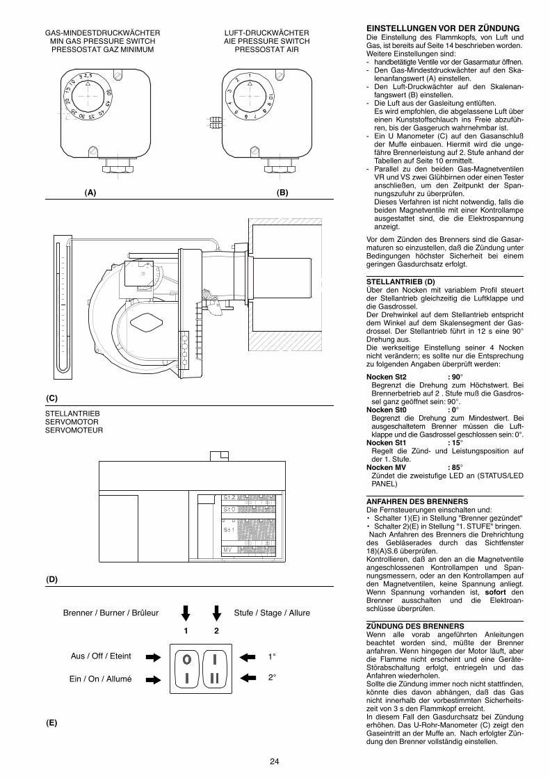
24
EINSTELLUNGEN VOR DER Z�NDUNGDie Einstellung des Flammkopfs, von Luft undGas, ist bereits auf Seite 14 beschrieben worden. Weitere Einstellungen sind:- handbet�tigte Ventile vor der Gasarmatur �ffnen.- Den Gas-Mindestdruckw�chter auf den Ska-
lenanfangswert (A) einstellen.- Den Luft-Druckw�chter auf den Skalenan-
fangswert (B) einstellen.- Die Luft aus der Gasleitung entl�ften.
Es wird empfohlen, die abgelassene Luft �bereinen Kunststoffschlauch ins Freie abzuf�h-ren, bis der Gasgeruch wahrnehmbar ist.
- Ein U Manometer (C) auf den Gasanschlu§der Muffe einbauen. Hiermit wird die unge-f�hre Brennerleistung auf 2. Stufe anhand derTabellen auf Seite 10 ermittelt.
- Parallel zu den beiden Gas-MagnetventilenVR und VS zwei Gl�hbirnen oder einen Testeranschlie§en, um den Zeitpunkt der Span-nungszufuhr zu �berpr�fen. Dieses Verfahren ist nicht notwendig, falls diebeiden Magnetventile mit einer Kontrollampeausgestattet sind, die die Elektrospannunganzeigt.
Vor dem Z�nden des Brenners sind die Gasar-maturen so einzustellen, da§ die Z�ndung unterBedingungen h�chster Sicherheit bei einemgeringen Gasdurchsatz erfolgt.
STELLANTRIEB (D)�ber den Nocken mit variablem ProÞl steuertder Stellantrieb gleichzeitig die Luftklappe unddie Gasdrossel. Der Drehwinkel auf dem Stellantrieb entsprichtdem Winkel auf dem Skalensegment der Gas-drossel. Der Stellantrieb f�hrt in 12 s eine 90°Drehung aus. Die werkseitige Einstellung seiner 4 Nockennicht ver�ndern; es sollte nur die Entsprechungzu folgenden Angaben �berpr�ft werden:
Nocken St2 : 90°Begrenzt die Drehung zum H�chstwert. BeiBrennerbetrieb auf 2 . Stufe mu§ die Gasdros-sel ganz ge�ffnet sein: 90°.
Nocken St0 : 0°Begrenzt die Drehung zum Mindestwert. Beiausgeschaltetem Brenner m�ssen die Luft-klappe und die Gasdrossel geschlossen sein: 0°.
Nocken St1 : 15°Regelt die Z�nd- und Leistungsposition aufder 1. Stufe.
Nocken MV : 85°Z�ndet die zweistuÞge LED an (STATUS/LEDPANEL)
ANFAHREN DES BRENNERSDie Fernsteuerungen einschalten und:¥ Schalter 1)(E) in Stellung "Brenner gez�ndet"¥ Schalter 2)(E) in Stellung "1. STUFE" bringen. Nach Anfahren des Brenners die Drehrichtungdes Gebl�serades durch das Sichtfenster18)(A)S.6 �berpr�fen.Kontrollieren, da§ an den an die Magnetventileangeschlossenen Kontrollampen und Span-nungsmessern, oder an den Kontrollampen aufden Magnetventilen, keine Spannung anliegt.Wenn Spannung vorhanden ist, sofort denBrenner ausschalten und die Elektroan-schl�sse �berpr�fen.
Z�NDUNG DES BRENNERSWenn alle vorab angef�hrten Anleitungenbeachtet worden sind, m�§te der Brenneranfahren. Wenn hingegen der Motor l�uft, aberdie Flamme nicht erscheint und eine Ger�te-St�rabschaltung erfolgt, entriegeln und dasAnfahren wiederholen.Sollte die Z�ndung immer noch nicht stattÞnden,k�nnte dies davon abh�ngen, da§ das Gasnicht innerhalb der vorbestimmten Sicherheits-zeit von 3 s den Flammkopf erreicht.In diesem Fall den Gasdurchsatz bei Z�ndungerh�hen. Das U-Rohr-Manometer (C) zeigt denGaseintritt an der Muffe an. Nach erfolgter Z�n-dung den Brenner vollst�ndig einstellen.
(A)
(C)
(D)
1 2
Brenner / Burner / Br�leur Stufe / Stage / Allure
1°
2°
(E)
(B)
GAS-MINDESTDRUCKW�CHTERMIN GAS PRESSURE SWITCHPRESSOSTAT GAZ MINIMUM
LUFT-DRUCKW�CHTERAIE PRESSURE SWITCH
PRESSOSTAT AIR
STELLANTRIEBSERVOMOTORSERVOMOTEUR
Aus / Off / Eteint
Ein / On / Allum�

25
ADJUSTMENTS BEFORE FIRST FIRINGAdjustment of the combustion head, and air andgas deliveries has been illustrated on page 14.In addition, the following adjustments must alsobe made:- open manual valves up-line from the gas
train.- Adjust the minimum gas pressure switch to
the start of the scale (A).- Adjust the air pressure switch to the zero
position of the scale (B).- Purge the air from the gas line.
Continue to purge the air (we recommendusing a plastic tube routed outside the build-ing) until gas is smelt.
- Fit a U-type manometer (C) to the gas pres-sure test point on the sleeve.The manometer readings are used to calcu-late the 2nd stage operation burner powerusing the tables on page 10.
- Connect two lamps or testers to the two gasline solenoid valves VR and VS to check theexact moment at which voltage is supplied.This operation is unnecessary if each of thetwo solenoid valves is equipped with a pilotlight that signals voltage passing through.
Before starting up the burner it is good practiceto adjust the gas train so that ignition takesplace in conditions of maximum safety, i.e. withgas delivery at the minimum.
SERVOMOTOR (D)The servomotor provides simultaneous adjust-ment of the air gate valve, by means of the vari-able proÞle cam, and the gas butterßy valve.The angle of rotation of the servomotor is equalto the angle on the graduated sector controllingthe gas butterßy valve. The servomotor rotatesthrough 90 degrees in 12 seconds.Do not alter the factory setting for the 4 cams;simply check that they are set as indicatedbelow:
Cam St2 : 90°Limits rotation toward maximum position. Whenthe burner is in 2nd stage operation the gas but-terßy valve must be fully open: 90°.Cam St0 : 0°Limits rotation toward the minimum position.When the burner is shut down the air gate valveand the gas butterßy valve must be closed: 0°.Cam St1 : 15°Adjusts the ignition position and the output in1st stage operation.Cam MV : 85°Lights up the 2nd stage LED (STATUS/LEDPANEL)
BURNER STARTINGClose the control devices and set:¥ switch 1)(E) to "Burner ON" position¥ switch 2)(E) to "1st STAGE" position.As soon as the burner starts check the directionof rotation of the fan blade, looking through theßame inspection window 18)(A)p.6.Make sure that the lamps or testers connectedto the solenoids, or pilot lights on the solenoidsthemselves, indicate that no voltage is present.If voltage is present, then immediately stop theburner and check electrical connections.
BURNER FIRINGHaving completed the checks indicated in theprevious heading, the burner should Þre. If themotor starts but the ßame does not appear andthe control box goes into lock-out, reset and waitfor a new Þring attempt. If Þring is still not achieved, it may be that gas isnot reaching the combustion head within thesafety time period of 3 seconds. In this case increase gas Þring delivery. The arrival of gas at the sleeve is indicated bythe U-type manometer (C).Once the burner has Þred, now proceed withglobal calibration operations.
REGLAGES AVANT L'ALLUMAGELe r�glage de la t�te de combustion, air et gaz,a d�j� �t� d�crit page 14.Les autres r�glages � effectuer sont les suivants:- ouvrir les vannes manuelles situ�es en amont
de la rampe du gaz.- R�gler le pressostat de seuil minimum gaz en
d�but d'�chelle (A).- R�gler le pressostat air en d�but d'�chelle (B).- Purger le conduit gaz de l'air.
Il est conseill� d'�vacuer l'air purg� en dehorsdes locaux par un tuyau en plastique jusqu'� ceque l'on sente l'odeur caract�ristique du gaz.
- Monter un manom�tre en U (C) sur la prisede pression de gaz du manchon.Celui-ci servira � mesurer approximativementla puissance du br�leur en 2�me allure �l'aide du tableau page 10.
- Raccorder en parall�le aux deux �lectrovan-nes de gaz VR et VS deux lampes ou testeurspour contr�ler le moment de la mise sous ten-sion.Cette op�ration n'est pas n�cessaire si cha-cune des deux electrovannes est munie d'unvoyant lumineux signalant la tension �lectri-que.
Avant d'allumer le br�leur, r�gler la rampe dugaz aÞn que l'allumage se fasse dans les condi-tions de s�curit� maximum, c'est � dire avec und�bit de gaz tr�s faible.
SERVOMOTEUR (D)Le servomoteur r�gle en m�me temps le voletd'air par la came � proÞl variable et la vannepapillon du gaz. L'angle de rotation sur le servomoteur est �gal �l'angle sur le secteur gradu� de la vannepapillon gaz. Le servomoteur pivote de 90° en12 secondes. Ne pas modiÞer le r�glage des 4cames �quipant l'appareil effectu� en usine.Contr�ler simplement que ces cames soientr�gl�es comme suit:
Came St2 : 90°Limite la rotation vers le maximum.Le br�leur fonctionnant en 2�me allure, la vannepapillon doit �tre ouverte compl�tement: 90°Came St0 : 0°Limite la rotation vers le minimum.Br�leur �teint, le volet de l'air et la vannepapillon doivent �tre ferm�s: 0°Came St1 : 15°R�gle la position d'allumage et de puissance en1�re allure.Came MV : 85°Allume le voyant lumineux de la 2�me allure(STATUS/LED PANEL).
DEMARRAGE BRULEURFermer les t�l�commandes et mettre:¥ l'interrupteur 1)(E) en position "Br�leur allum�"¥ l'interrupteur 2)(E) en position "1�re ALLURE".D�s que le br�leur d�marre contr�ler le sens derotation du rotor turbine par le viseur ßamme18)(A)p.6.V�riÞer que les ampoules ou les testeurs rac-cord�s aux �lectrovannes, ou les voyants surles �lectrovannes, indiquent une absence detension. S'ils signalent une tension, arr�terimm�diatement le br�leur et contr�ler les rac-cordements �lectriques.
ALLUMAGE BRULEURApr�s avoir effectu� les op�rations d�crites aupoint pr�c�dent, le br�leur devrait s'allumer. Sile moteur d�marre mais la ßamme n'appara�tpas et le bo�tier de contr�le se bloque, r�armeret faire une nouvelle tentative de d�marrage.Si l'allumage ne se fait pas, il se peut que le gazn'arrive pas � la t�te de combustion dans letemps de s�curit� de 3 s. Dans ce cas augmen-ter le d�bit du gaz � l'allumage. L'arriv�e du gazau manchon est mise en �vidence par le mano-m�tre en U (C). Quand l'allumage est fait, passer au r�glagecomplet du br�leur.
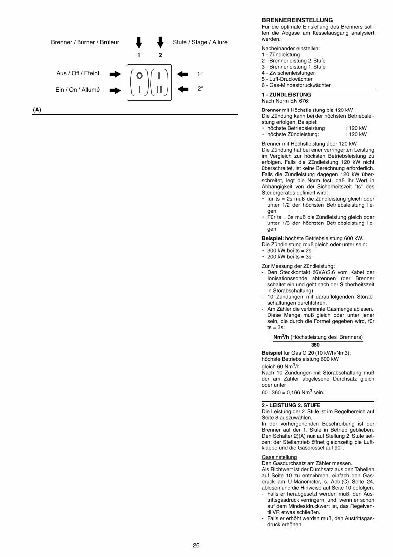
26
BRENNEREINSTELLUNGF�r die optimale Einstellung des Brenners soll-ten die Abgase am Kesselausgang analysiertwerden.
Nacheinander einstellen:1 - Z�ndleistung2 - Brennerleistung 2. Stufe3 - Brennerleistung 1. Stufe4 - Zwischenleistungen5 - Luft-Druckw�chter6 - Gas-Mindestdruckw�chter
1 - Z�NDLEISTUNGNach Norm EN 676:
Brenner mit H�chstleistung bis 120 kWDie Z�ndung kann bei der h�chsten Betriebslei-stung erfolgen. Beispiel:¥ h�chste Betriebsleistung : 120 kW¥ h�chste Z�ndleistung: : 120 kW
Brenner mit H�chstleistung �ber 120 kWDie Z�ndung hat bei einer verringerten Leistungim Vergleich zur h�chsten Betriebsleistung zuerfolgen. Falls die Z�ndleistung 120 kW nicht�berschreitet, ist keine Berechnung erforderlich.Falls die Z�ndleistung dagegen 120 kW �ber-schreitet, legt die Norm fest, da§ ihr Wert inAbh�ngigkeit von der Sicherheitszeit "ts" desSteuerger�tes deÞniert wird:¥ f�r ts = 2s mu§ die Z�ndleistung gleich oder
unter 1/2 der h�chsten Betriebsleistung lie-gen.
¥ F�r ts = 3s mu§ die Z�ndleistung gleich oderunter 1/3 der h�chsten Betriebsleistung lie-gen.
Beispiel: h�chste Betriebsleistung 600 kW.Die Z�ndleistung mu§ gleich oder unter sein:¥ 300 kW bei ts = 2s¥ 200 kW bei ts = 3s
Zur Messung der Z�ndleistung:- Den Steckkontakt 26)(A)S.6 vom Kabel der
Ionisationssonde abtrennen (der Brennerschaltet ein und geht nach der Sicherheitszeitin St�rabschaltung).
- 10 Z�ndungen mit darauffolgenden St�rab-schaltungen durchf�hren.
- Am Z�hler die verbrennte Gasmenge ablesen. Diese Menge mu§ gleich oder unter jenersein, die durch die Formel gegeben wird, f�rts = 3s:
Beispiel f�r Gas G 20 (10 kWh/Nm3):h�chste Betriebsleistung 600 kW gleich 60 Nm3/h.Nach 10 Z�ndungen mit St�rabschaltung mu§der am Z�hler abgelesene Durchsatz gleichoder unter 60 : 360 = 0,166 Nm3 sein.
2 - LEISTUNG 2. STUFEDie Leistung der 2. Stufe ist im Regelbereich aufSeite 8 auszuw�hlen. In der vorhergehenden Beschreibung ist derBrenner auf der 1. Stufe in Betrieb geblieben.Den Schalter 2)(A) nun auf Stellung 2. Stufe set-zen: der Stellantrieb �ffnet gleichzeitig die Luft-klappe und die Gasdrossel auf 90°.
GaseinstellungDen Gasdurchsatz am Z�hler messen. Als Richtwert ist der Durchsatz aus den Tabellenauf Seite 10 zu entnehmen, einfach den Gas-druck am U-Manometer, s. Abb.(C) Seite 24,ablesen und die Hinweise auf Seite 10 befolgen.- Falls er herabgesetzt werden mu§, den Aus-
trittsgasdruck verringern, und, wenn er schonauf dem Mindestdruckwert ist, das Regelven-til VR etwas schlie§en.
- Falls er erh�ht werden mu§, den Austrittsgas-druck erh�hen.
(A)
1 2
Brenner / Burner / Br�leur Stufe / Stage / Allure
2°
Aus / Off / Eteint
Ein / On / Allum�
1°
Nm3/h (H�chstleistung des Brenners)
360

27
BURNER CALIBRATIONThe optimum calibration of the burner requiresan analysis of the ßue gases at the boiler outlet.
Adjust successively:1 - First Þring output2 - 2nd stage burner output3 - 1st stage burner output4 - Intermediate outputs between 1st and 2nd
stage5 - Air pressure switch6 - Minimum gas pressure switch
1 - FIRING OUTPUTAccording to EN 676 Regulations:
Burners with max. output up to 120 kWFiring can be performed at the maximum opera-tion output level. Example:¥ Max. operation output : 120 kW¥ Max. Þring output : 120 kW
Burners with max. output above 120 kWFiring must be performed at a lower output thanthe max. operation output. If the Þring outputdoes not exceed 120 kW, no calculations arerequired. If Þring output exceeds 120 kW, theregulations prescribe that the value be deÞnedaccording to the control box safety time "ts":¥ for "ts" = 2s, Þring output must be equal to or
lower than 1/2 of max. operation output.¥ For "ts" = 3s, Þring output must be equal to or
lower than 1/3 of max. operation output.
Example: MAX operation output of 600 kW.Firing output must be equal to or lower than:¥ 300 kW with "ts" = 2s¥ 200 kW with "ts" = 3s
In order to measure the Þring output:- Disconnect the plug-socket 26)(A)p.6 on the
ionization probe cable (the burner will Þre andthen go into lock-out after the safety time haselapsed).
- Perform 10 Þrings with consecutive lock-outs.- On the meter read the quantity of gas burned.
This quantity must be equal to or lower thanthe quantity given by the formula, for ts = 3s:
Example for G 20 gas (10 kWh/Nm3):Max. operation output: 600 kW corresponding to
60 Nm3/h.After 10 Þrings with lock-outs, the delivery readon the meter must be equal to or lower than:
60 : 360 = 0,166 Nm3.
2 - 2ND STAGE OUTPUT2nd stage output of the burner must be setwithin the Þring rate range shown on page 8.In the above instructions we left the burner run-ning in 1st stage operation. Now set switch 2)(A)to the 2nd stage position: the servomotor willopen, simultaneously, the air gate valve and thegas butterßy valve to 90°.
Gas calibrationMeasure the gas delivery at the meter.A guideline indication can be calculated from thetables on page 10, simply read off the gas pres-sure on the U-type manometer, see Þg.(C) onpage 24, and follow the instructions on page 10.- If delivery needs to be reduced, diminish out-
let gas pressure and, if it is already very low,slightly close adjustment valve VR.
- If delivery needs to be increased, increaseoutlet gas pressure.
Nm3/h (max. burner delivery )360
REGLAGE BRULEURPour obtenir un r�glage optimal du br�leur, ilfaut effectuer l'analyse des gaz d'�chappementde la combustion � la sortie de la chaudi�re.
R�gler en succession:1 - Puissance � l'allumage: 2 - Puissance br�leur en 2�me allure 3 - Puissance br�leur en 1�re allure 4 - Puissances interm�diaires entre les deux 5 - Pressostat air 6 - Pressostat seuil minimum du gaz
1 - PUISSANCE A L'ALLUMAGESelon la norme EN 676:
Br�leurs avec puissance MAX jusqu'� 120 kWL'allumage peut se faire � la puissance maxi-mum de fonctionnement. Exemple:¥ Puissance max de fonctionnement :120 kW¥ Puissance max � l'allumage :120 kW
Br�leurs � puissance MAX au del� des 120 kWL'allumage doit se faire � une puissance r�duitepar rapport � la puissance maximum de fonc-tionnement. Si la puissance � l'allumage ned�passe pas les 120 kW, aucun calcul n'estn�cessaire. Au contraire, si la puissance � l'allu-mage d�passe les 120 kW, la norme �tablit quesa valeur soit d�Þnie en fonction du temps des�curit� "ts" du coffret de s�curit�:¥ pour ts = 2s la puissance � l'allumage doit
�tre �gale ou inf�rieure � 1/2 de la puissancemaximum de fonctionnement.
¥ Pour ts = 3s la puissance � l'allumage doit�tre �gale ou inf�rieure � 1/3 de la puissancemaximum de fonctionnement.
Exemple: puissance MAX de fonctionnement600 kW. La puissance � l'allumage doit �tre�gale ou inf�rieure �:¥ 300 kW avec ts = 2s¥ 200 kW avec ts = 3s
Pour mesurer la puissance � l'allumage:- D�brancher la Þche-prise 26)(A)p.6 sur le c�ble
de la sonde d'ionisation (le br�leur s'allume etse bloque apr�s le temps de s�curit�).
- Ex�cuter 10 allumages avec blocages cons�-cutifs.
- Lire au compteur la quantit� de gaz br�l�e.Cette quantit� doit �tre �gale ou inf�rieure �celle donn�e par la formule, pour ts = 3s:
Exemple pour du gaz G 20 (10 kWh/Nm3):puissance maximum de fonctionnement, 600 kW
correspondants � 60 Nm3/h.Apr�s 10 allumages avec blocage le d�bit lu aucompteur doit �tre �gal ou inf�rieur �:
60 : 360 = 0,166 Nm3.
2 - PUISSANCE EN 2EME ALLURELa puissance en 2�me allure doit �tre choisiedans la plage indiqu�e page 8.La description ci-dessus s'entend br�leurallum� fonctionnant en 1�re allure. Placer main-tenant l'interrupteur 2)(A) en position 2�meallure: le servomoteur ouvrira le volet d'air etsimultan�ment le papillon de gaz � 90°.
R�glage du gazMesurer le d�bit du gaz sur le compteur.A titre indicatif, ce d�bit peut �tre trouv� sur lestableaux page 10. Il sufÞt de lire la pression dugaz sur le manom�tre en U, comme indiqu� Þg.(C) page 24, et de suivre les indications page 10.- S'il est n�cessaire de la r�duire, diminuer la
pression du gaz en sortie et, si elle est d�j�au minimum, fermer un peu la vanne der�glage VR.
- S'il est n�cessaire de l'augmenter, accro�trela pression du gaz en sortie.
Nm3/h (d�bit max. br�leur)360

28
Lufteinstellung�ber die Schrauben des Nockes im Inneren der�ffnung 6)(A) das EndproÞl des Nocken 4)(A)ver�ndern.- Zur Erh�hung des Luftdurchsatzes die
Schrauben zudrehen.- Zur Reduzierung des Luftdurchsatzes die
Schrauben abdrehen.
3 - LEISTUNG 1. STUFEDie Leistung der 1. Stufe ist im Regelbereich aufSeite 8 auszuw�hlen. Schalter 2)(A)S.26 in Stellung 1. Stufe setzen:der Stellantrieb 1)(A) schlie§t die Luftklappe undgleichzeitig die Gasdrossel auf 15°, d.h. auf diewerkseitige Einstellung.
GaseinstellungDen Gasdurchsatz am Z�hler messen.- Zur Abnahme den Nockenwinkel St1 (B) mit
kleinen Verstellungen progressiv reduzieren,d.h. vom Winkel 15° auf 13° - 11° ...
- Zur Steigerung durch Schalter 2)(A)S.26 auf2. Stufe �bergehen und den NockenwinkelSt1 mit kleinen Verstellungen progressiv ver-gr�§ern, d.h. vom Winkel 15° auf 17° - 19° ...Daraufhin erneut auf 1. Stufe zur�ckfahrenund den Gasdurchsatz messen.
MerkeDer Stellantrieb folgt der Einstellung des Nok-ken St1 nur bei Reduzierung des Winkels. BeiVergr�§erung des Winkels mu§ man zuerst auf2. Stufe schalten, hier den Winkel steigern unddann auf die 1. Stufe zur�ckkehren, um dieWirksamkeit der Einstellung zu pr�fen.Wird der Winkel von St1 w�hrend des Brenner-betriebs auf 1. Stufe vergr�§ert, erfolgt die Aus-schaltung des Brenners.
Zur Einstellung des Nocken St1 ist der eingera-stete Deckel 1), s. Abb.(B) abzunehmen, dieentsprechende Feder 2) herauszuziehen und inden Schlitz des Nocken St1 einzustecken.
LufteinstellungProgressiv das AnfangsproÞl des Nocken 4)(A)�ber die Nockenschrauben in der �ffnung 6)(A)ver�ndern. Die erste Schraube m�glichst nichtverdrehen, mit dieser wird die Luftklappe ganzgeschlossen.
4 - ZWISCHENLEISTUNGENGaseinstellungKeine Einstellung ist erforderlich.
LufteinstellungBrenner durch Schalter 1)(A)S.26 abschalten,den Nocken mit variablem ProÞl durch vertikalePositionierung des Schlitzes 2)(A) am Stellan-trieb entsperren und die Zwischenschraubendes Nocken so einstellen, da§ die Nockennei-gung gleitend ist. Darauf achten, da§ die Schrauben an denEnden des vorab eingestellten Nocken f�r die�ffnung der Luftklappe auf der 1. und 2. Stufenicht versetzt werden.
MerkeNach Einstellung der Leistungen 2. - 1. - ZWI-SCHENSTUFE ist die Z�ndung nochmals zu�berpr�fen. Der Schalldruckpegel mu§ dem der anschlie-§enden Betriebsphase entsprechen. Bei Verpuf-fungen sollte der Z�nddurchsatz reduziertwerden.
(B)
(A)
1 Stellantrieb
2 Sperre/ Entsperrung Nocken 4
3 Nockendeckel
4 Nocken mit variablem ProÞl
5 Einstellschrauben des variablem ProÞls
6 Zugangsschlitz zu Schrauben 5
7 Zeiger des Skalensegments 8
8 Skalensegments Gasdrossel
1 Servomotor
2 Cam 4 engaged /disengages
3 Cam cover
4 Adjustable proÞle cam
5 Cam proÞle adjustment screws
6 Opening for access to screws 5
7 Index for graduated sector 8
8 Graduated sector for gas butterßy valve
1 Servomoteur
2 Verroillage / Deverroillage came 4
3 Couvercle cames
4 Came � proÞl variable
5 Vis de r�gulation du proÞl variable
6 Rainure dÕacc�s � la vis 5
7 Index du secteur gradu� 8
8 Secteuer gradu� vanne papillon gaz

29
Adjusting air deliveryProgressively adjust the end proÞle of cam 4)(A)by turning the cam adjustment screws as theyappear through the access opening 6)(A).- Turn the screws clockwise to increase air
delivery.- Turn the screws counter-clockwise to reduce
air delivery.
3 - 1ST STAGE OUTPUTBurner power in 1st stage operation must beselected within the Þring rate range shown onpage 8.Set the switch 2)(A)p.26 to the 1st stage posi-tion: the servomotor 1)(A) will close the air gatevalve and, at the same time, closes the gas but-terßy valve down to 15°, i.e. down to the originalfactory setting.
Adjusting gas deliveryMeasure the delivery of gas from the gas meter.- If this value is to be reduced, decrease the
angle of cam St1 (B) slightly by proceeding alittle at a time until the angle is changed from15° to 13° or 11°....
- If it is necessary to increase the mains pres-sure, move to 2nd stage operation by alteringthe setting of switch 2)(A)p.26 and increasethe angle of cam St1, proceeding a little at atime until the angle is changed from 15° to17° - 19°....At this point return to 1st stage operation andmeasure gas delivery.
NotaThe servomotor follows the adjustment of camSt1 only when the angle is reduced. If, howeverthe angle must be increased, switch to 2ndstage operation, increase the angle and thenreturn to 1st stage operation to check the effectof the adjustment.If you increase the angle of St1 while the burneris operating in 1st stage, lock-out will result.
In order to adjust cam St1, remove press-Þtcover 1), as shown in Þg.(B), extract the relevantkey 2) from inside, and Þt it into the keyway incam St1.
Adjustment of air deliveryProgressively adjust the starting proÞle of cam4)(A) by turning the screws working throught theaccess hole 6)(A). It is preferable not to turn theÞrst screw since this is used to set the air gatevalve to its fully-closed position.
4 - INTERMEDIATE OUTPUTSAdjustment of gas deliveryNo adjustment of gas delivery is required.
Adjustment of air deliverySwitch off the burner using switch 1)(A)p.26,disengage the variable proÞle cam, set the ser-vomotor shaft slot 2)(A) to a vertical position andturn the central screws of the cam so that thecam offers a progressive gradient. Try turningthe cam back and forth by hand a few times untilthe movement is completely smooth with nosigns of sticking.Do not alter the position of the screws at eachend of the cam track, which have already beenadjusted for 1st and 2nd stage air gate valvecontrol.
NotaOnce you have Þnished adjusting outputs 2NDSTAGE - 1ST STAGE - INTERMEDIATE, checkignition once again: noise emission at this stagemust be identical to the following stage of opera-tion. If you notice any sign of pulsations, reducethe ignition stage delivery.
R�glage de l'airModiÞer en progression le proÞl Þnal de la came4)(A) en agissant sur les vis de celle-ci quiapparaisent � lÕint�rieur de lÕouverture 6)(A).- Pour augmenter le d�bit d'air serrer les vis.- Pour diminuer celui-ci, desserrer les vis.
3 - PUISSANCE EN 1ERE ALLURELa puissance en 1�re allure doit �tre choisiedans la plage indiqu�e page 8. Mettre l'interrupteur 2)(A)p.26 en position 1�reallure: le servomoteur 1)(A) fermera le volet d'airet, simultan�ment, fermera la vanne-papillon degaz jusqu'� 15°, c'est � dire jusqu'� la valeurtar�e en usine.
R�glage du gazMesurer le d�bit du gaz au compteur.- S'il faut diminuer ce d�bit, r�duire l�g�rement
l'angle de la came St1 (B) par de l�gersd�placements successifs, c'est-�-dire aller del'angle 15° � 13-11°...
- S'il faut l'augmenter, passer en 2�me allure enagissant sur l'interrupteur 2)(A)p.26 et aug-menter l�g�rement l'angle de la came St1 parde l�gers d�placements successifs, c'est-�-dire aller de l'angle 15° � 17-19°...
Revenir ensuite en 1�re allure et mesurer led�bit du gaz.
NoteLe servomoteur suit le r�glage de la came St1uniquement lorsque l'angle est r�duit. Si l'ond�sire augmenter cet angle, il est n�cessaire depasser en 2�me allure, d'augmenter l'angle etde revenir en 1�re allure pour contr�ler l'effetdes r�glages.Si on augmente lÕangle de St1 quand le br�leurfonctionne en 1�re allure on aura lÕarr�t de cebr�leur.
Pour le r�glage �ventuel de la came St1 retirerle couvercle 1) enclench� par pression commeindiqu� Þg.(B), retirer la clavette 2) situ�e � int�-rieur et ins�rer celle-ci dans la fente de la cameSt1.
R�glage de l'airModiÞer en progression le proÞl initial de lacame 4)(A) en agissant sur les vis de celle-ci quiapparaisent � lÕint�rieur de lÕouverture 6)(A). Sipossible, ne pas serrer la premi�re vis: il s'agitde la vis qui ferme compl�tement le volet del'air.
4 - PUISSANCES INTERMEDIAIRESR�glage du gazLe r�glage n'est pas n�cessaire.
R�glage de l'airEteindre le br�leur en actionnant l'interrupteur1)(A)p.26, retirer la came � proÞl variable en pla-�ant la fente 2)(A) du servomoteur en positionverticale et intervenir sur les vis interm�diairesde la came pour que l'inclinaison de celle-ci soitprogressive. Essayer plusieurs fois en faisant tournermanuellement la came dÕavant en arri�re: lemouvement doit �tre doux sans accrocs.Faire attention de ne pas d�placer les vis auxextr�mit�s de la came, celles-ci ont �t� r�gl�esau pr�alable pour l'ouverture du volet en 1�re et2 �me allure.
NoteD�s que le r�glage des puissances 2EMEALLURE - 1ERE ALLURE - INTERMEDIAIRESest termin�, contr�ler l'allumage. Celui-ci doitproduire un son identique au son du fonctionne-ment qui s'ensuit. En cas de saccades, r�duirele d�bit � l'allumage.

30
5 - LUFTDRUCKW�CHTER (A)Die Einstellung des Luftdruckw�chters erfolgtnach allen anderen Brennereinstellungen; derDruckw�chter wird auf Skalenbeginn (A) einge-stellt. Bei Brennerbetrieb auf 1° Stufe den Einstell-druck durch Drehen des daf�r bestimmtenDrehknopfs im Uhrzeigersinn langsam erh�henbis eine St�rabschaltung erfolgt. Dann den Drehknopf gegen den Uhrzeigersinnum etwa 20% des eingestellten Druckwerteszur�ckdrehen und den Brenner wieder anfah-ren, um zu �berpr�fen, ob dieser ordnungsge-m�§ arbeitet. Sollte eine St�rabschaltung eintreten, den Dreh-knopf ein bi§chen wieder noch zur�ckdrehen.
AchtungAls Regel gilt, da§ der Luftdruckw�chter verhin-dern mu§, da§ das CO im Abgas 1% (10.000ppm) �berschreitet. Um das sicherzustellen, einen Verbrennungs-analysator in den Kamin einf�gen, die Ansaug-�ffnung des Gebl�ses langsam schlie§en (zumBeispiel mit Pappe) und pr�fen, da§ die St�rab-schaltung des Brenners erfolgt, bevor das CO inden Abgasen 1% �berschreitet.
Der eingebaute Luftdruckw�chter ist ein Diffe-rentialschalter. Falls ein starker Unterdruck inder Brennkammer bei der Vorbel�ftung es demLuftdruckw�chter umschalten nicht gestattensollte, can man ein Rohr zwischen Luftdruck-w�chter und Ansaug�ffnung des Gebl�sesanbringen. So wird der Luftdruckw�chter als Dif-ferentialschalter arbeiten.
AchtungDer Gebrauch des Luftdruckw�chters als Diffe-rentialschalter ist nur f�r Industrieanwendungenzugelassen. Er ist auch dort zugelassen, wo lautVorschriften der Luftdruckw�chter nur denGebl�sebetrieb, ohne Bezug auf CO-Grenzen,�berwacht.
6 - GAS-MINIMALDRUCKW�CHTER (B)Die Einstellung des Gas-Minimaldruckw�chterserfolgt nach allen anderen Brennereinstellun-gen, wobei der W�chter auf Skalenbeginn (B)eingestellt wird. Bei Brennerbetrieb auf 2° Stufe den Einstell-druck durch Drehen des daf�r bestimmtenDrehknopfs im Uhrzeigersinn langsam erh�hen,bis der Brenner ausschaltet. Dann den Drehknopf gegen den Uhrzeigersinnum 2 mbar zur�ckdrehen und den Brenner wie-der anfahren, um zu �berpr�fen, ob dieser ord-nungsgem�§ arbeitet. Sollte der Brenner wieder ausschalten, denDrehknopf noch einmal gegen den Uhrzeiger-sinn um 1 mbar drehen.
FLAMMEN�BERWACHUNG (C)Der Brenner ist mit einem Ionisationsger�t zurFlammen�berwachung ausger�stet. Der erfor-derliche Mindeststrom betr�gt 5 mA. Da derBrenner einen weitaus h�heren Strom erreicht,sind normalerweise keine Kontrollen n�tig. Willman den Ionisationsstrom messen, mu§ derSteckanschlu§ 26)(A)S.6 am Kabel der Ionisati-onssonde ausgeschaltet und ein Gleichstrom-Mikroamperemeter, Me§bereich 100 mA, einge-schaltet werden. Auf richtige Polung achten!
(A)
(C)
LUFT-DRUCKW�CHTER 5)(A)S.6AIR PRESSURE SWITCH 5)(A)p.6PRESSOSTAT AIR 5)(A)p.6
GAS-MINDESTDRUCKW�CHTER 7)(B)S.16MIN GAS PRESSURE SWITCH 7)(B)p.16PRESSOSTAT GAZ MINIMUM 7)(B)p.16
(B)

31
5 - AIR PRESSURE SWITCH (A)Adjust the air pressure switch after having per-formed all other burner adjustments with the airpressure switch set to the start of the scale (A).With the burner operating in 1st stage, increaseadjustment pressure by slowly turning the rela-tive knob clockwise until the burner locks out.Then turn the knob anti-clockwise by about 20%of the set point and repeat burner starting toensure it is correct.If the burner locks out again, turn the knob anti-clockwise a little bit more.
AttentionAs a rule, the air pressure switch must limit theCO in the fumes to less than 1% (10,000 ppm).To check this, insert a combustion analyser intothe chimney, slowly close the fan suction inlet(for example with cardboard) and check that theburner locks out, before the CO in the fumesexceeds 1%.
The air pressure switch may operate in "differ-ential" operation in two pipe system. If a nega-tive pressure in the combustion chamber duringpre-purging prevents the air pressure switchfrom switching, switching may be obtained by Þt-ting a second pipe between the air pressureswitch and the suction inlet of the fan. In such amanner the air pressure switch operates as dif-ferenzial pressure switch.
WarningThe use of the air pressure switch with differen-tial operation is allowed only in industrial appli-cations and where rules enable the air pressureswitch to control only fan operation without anyreference to CO limit.
6 - MINIMUM GAS PRESSURE SWITCH (B)Adjust the minimum gas pressure switch afterhaving performed all the other burner adjust-ments with the pressure switch set at the start ofthe scale (B).With the burner operating in 2nd stage, increaseadjustment pressure by slowly turning the rela-tive knob clockwise until the burner locks out.Then turn the knob anti-clockwise by 2 mbarand repeat burner starting to ensure it is uni-form.If the burner locks out again, turn the knob anti-clockwise again by 1 mbar.
FLAME PRESENT CHECK (C)The burner is Þtted with an ionisation systemwhich ensures that a ßame is present. The mini-mum current for plant operation is 5 mA. The burner provides a much higher current, sothat controls are not normally required. How-ever, if it is necessary to measure the ionisationcurrent, disconnect the plug-socket 26)(A)p.6 onthe ionisation probe cable and insert a directcurrent microamperometer with a base scale of100 mA. Carefully check polarities!
5 - PRESSOSTAT DE L'AIR (A)Effectuer le r�glage du pressostat de l'air apr�savoir effectu� tous les autres r�glages du br�-leur avec le pressostat de l'air r�gl� en d�butd'�chelle (A). Lorsque le br�leur fonctionne en1�re allure, augmenter la pression de r�glageen tournant lentement dans le sens desaiguilles d'une montre la petite molette pr�vue �cet effet jusqu'au blocage du br�leur. Tourner ensuite dans le sens contraire la petitemolette du 20% du valeur regl� et r�p�ter led�marrage du br�leur pour en v�riÞer la r�gula-rit�. Si le br�leur se bloque � nouveau, tournerencore un peu la petite molette dans le senscontraire aux aiguilles d'une montre.
Attention Comme le veut la norme, le pressostat de l'airdoit emp�cher que le CO dans les fum�esd�passe 1% (10.000 ppm).Pour s'en rendre compte, ins�rer un analyseurde combustion dans le conduit, fermer lente-ment la bouche d'aspiration du ventilateur (parexemple avec un carton) et v�riÞer qu'il y ait blo-cage du br�leur, avant que le CO dans lesfum�es ne d�passe 1%.
Le pressostat de l'air install� peut fonctionner defa�on diff�rentiel si il est joint avec deux tuyaux.Lors de la phase de pr�ventilation, si une forted�pression dans la chambre de combustionemp�che le pressostat de l'air de commuter, lacommutation peut �tre obtenue installant undeuxi�me tuyau entre le pressostat de l'air et labouche d'aspiration du ventilateur. Dans cettefa�on le pressostat fonctionera comme un pres-sostat diff�rentiel.
AttentionOn ne peut utiliser le pressostat de l'air � fonc-tionnement diff�rentiel que dans des applica-tions industrielles et quand les normespermettent que le pressostat de l'air ne contr�leque le fonctionnement du ventilateur, sans limitde r�f�rence pour le CO.
6 - PRESSOSTAT GAZ SEUIL MINIMUM (B)Effectuer le r�glage du pressostat gaz seuil min.apr�s avoir effectu� tous les autres r�glages dubr�leur avec le pressostat r�gl� en d�butd'�chelle (B). Lorsque le br�leur fonctionne en 2�me allure,augmenter la pression de r�glage en tournantlentement dans le sens des aiguilles d'une mon-tre la petite molette pr�vue � cet effet jusqu'�l'arr�t du br�leur. Tourner ensuite dans le sens contraire la petitemolette de 2 mbar et r�p�ter le d�marrage dubr�leur pour en v�riÞer la r�gularit�. Si le br�-leur s' arr�te � nouveau, tourner encore dans lesens inverse aux aiguilles d'une montre de 1mbar.
CONTROLE PRESENCE FLAMME (C)Le br�leur est muni d'un syst�me � ionisationpour contr�ler la pr�sence de la ßamme. Pourfaire fonctionner le bo�tier de contr�le le courantminimum est de 5 mA. Le br�leur produit un cou-rant nettement sup�rieur qui ne n�cessite nor-malement d'aucun contr�le. Toutefois, si on veutmesurer le courant d'ionisation, il faut d�con-necter la Þche-prise 26)(A)p.6 plac�e sur lec�ble de la sonde d'ionisation et connecter unmicroamp�rem�tre pour courant continu de 100mA bas d'�chelle. Attention � la polarit�!

32
BRENNERBETRIEBANFAHREN DES BRENNERS (A)¥ : Abschalten Fernsteuerung TL.
Anfahren Stellmotor: dreht nachrechts bis zum am Nocken St1 einge-stellten Winkel. Nach etwa 3s:
¥ 0s : Die Anlaufphase hat angefangen.¥ 9s : Anfahren Gebl�semotor.
Anfahren Stellmotor: dreht nachrechts bis zum Eingriff des Schalt-st�cks am Nocken St2. Die Luftklappe positioniert sich aufLeistung der 2. Stufe.
¥ 18s : Vorbel�ftungsphase bei Luftdurchsatzwie bei 2. Stufe Leistung. Dauer 28 Sekunden.
¥ 46s : Anfahren Stellmotor: dreht nach linksbis zum am Nocken St1 eingestelltenWinkel.
¥ 55s : Die Luftklappe und die Gasdrosselpositionieren sich auf 1. Stufe Lei-stung.
¥ 56s : Funkenbildung an der Z�ndungselek-trode.
¥ 59s : Das Sicherheitsmagnetventil VS unddas Regelventil VR, schnell�ffnend,�ffnen sich und es erfolgt eine Flam-menbildung mit niedriger Leistung,Punkt A. Es erfolgt eine progressive Steigerungder Leistung, mit langsamer �ffnungdes Ventils bis zur Leistung, 1. Stufe,Punkt B.
¥ 61,5s : Der Funke erlischt.¥ 65s : Ist die Fernsteuerung TR geschlossen
bzw. �berbr�ckt, dreht der Stellantriebbis zum Eingriff des Nocken St2 weiterund bringt die Luftklappe und die Gas-drossel auf Position 2. Stufe, StreckeC-D.
¥ 80s : Das Programm des Steuerger�ts istbeendet, Punkt E.
DAUERBETRIEB (A)Anlage mit TR-FernsteuerungNach dem Anfahrzyklus geht die Steuerung desStellmotors zur TR-Fernsteuerung �ber, dieTemperatur oder den Druck im Kessel �ber-wacht, Punkt E. (Das Steuerger�t �berwacht weiterhin das Vor-handensein der Flamme sowie die richtige Stel-lung des Luftdruckw�chters).¥ Wenn die Temperatur oder der Druck bis zur
�ffnung von TR zunimmt, schlie§t der Stell-motor die Gasdrossel und die Luftklappe undder Brenner geht von der 2° zur 1° Funktions-stufe �ber, Strecke F-G.
¥ Wenn Temperatur oder Druck bis zum Ver-schlu§ von TR abnimmt, �ffnet der Stellmotordie Gasdrossel und die Luftklappe und derBrenner geht von der 1° zur 2° Funktionsstufe�ber, und so weiter.
¥ Das Ausschalten des Brenners erfolgt, wennder Bedarf an W�rme kleiner als die vomBrenner in der 1° Stufe gelieferte Menge ist,Strecke H-I. Die Fernsteuerung TL �ffnet sich,der Stellantrieb kehrt auf den durch NockenSt0 begrenzten Winkel 0° zur�ck. Die Klappeschlie§t sich vollst�ndig zwecks Reduzierungdes W�rmeverlusts.
Anlage ohne TR, mit �berbr�ckung.Das Anfahren des Brenners erfolgt wie obenbeschrieben. Wenn danach die Temperatur oderder Druck bis zum �ffnen von TL zunimmt, gehtder Brenner aus (Linie A-A des Diagramms).
MANGELNDE Z�NDUNG (B)Wenn der Brenner nicht z�ndet, erfolgt eineSt�rabschaltung innerhalb von 3 s ab dem �ff-nen des Gasventils und 65 s nach dem Ver-schlu§ von TL. Die Kontrollampe des Ger�ts leuchet auf.
ABSCHALTUNG W�HREND DES BRENNER-BETRIEBSErlischt die Flamme zuf�llig w�hrend des Bren-nerbetriebs, erfolgt nach 1 s die St�rabschal-tung des Brenners.
(A)
(B)
ORDNUNGSGEM�SSEN Z�NDEN(n° = Sekunden ab Zeitpunkt 0)
NICHTZ�NDEN / NO FIRING / LE BRULEUR SÕALLUME PAS
NORMAL FIRING(n° = seconds from instant 0)
ALLUMAGE REGULIER(n° = secondes � partir de lÕistant 0)

33
BURNER OPERATION
BURNER STARTING (A)¥ : Control device TL closes.
Servomotor starts: it rotates to right upto the angle set on cam St1.After about 3s:
¥ 0s : The control box starting cycle begins.¥ 9s : Fan motor starts.
Servomotor starts: it rotates to right,until contact is made on cam St2.The air gate valve is positioned to 2ndstage output.
¥ 18s : Pre-purge stage with air delivery at2nd stage output.Duration 28 seconds.
¥ 46s : Servomotor starts: it rotates to left upto the angle set on cam St1.
¥ 55s : The air gate valve and the gas butter-ßy are positioned to 1st stage output.
¥ 56s : Ignition electrode strikes a spark.¥ 59s : Safety valve VS and adjustment valve
VR (rapid opening) open. The ßame isignited at a low output level, point A.Output is then progressivelyincreased, with the valve openingslowly up to 1st stage output, point B.
¥ 61,5s : The spark goes out.¥ 65s : If remote control device TR is closed
or if it has been replaced by a jumper,the servomotor will continue to turnuntil the cam St2 come into operation,setting the air gate valve and the gasbutterßy valve to the 2nd stage opera-tion position, section C-D.
¥ 80s : The control box starting cycle ends,point E.
STEADY STATE OPERATION (A)System equipped with one control device TR.Once the starting cycle has come to an end,control of the servomotor passes on to the con-trol device TR that controls boiler temperature orpressure, point E.(The control box will continue, however, to moni-tor ßame presence and the correct position ofthe air pressure switch).¥ When the temperature or the pressure
increases until the control device TR opens,the servomotor closes the gas butterßy valveand the air gate valve and the burner passesfrom the 2nd to the 1st stage of operation,section F-G.
¥ When the temperature or pressure decreasesuntil the control device TR closes, the servo-motor opens the gas butterßy valve and theair gate valve and the burner passes from the1st to the 2nd stage of operation, and so on.
¥ The burner stops when the demand for heatis less than the amount of heat delivered bythe burner in the 1st stage, section H-I. Con-trol device TL now opens, the servomotorreturns toward the 0° position, limited in thismovement by cam St0. The air gate valvecloses completely to reduce heat losses to aminimum.
Systems not equipped with control device TR(jumper wire installed)The burner is Þred as described in the caseabove. If the temperature or pressure increaseuntil control device TL opens, the burner shutsdown (Section A-A in the diagram).
FIRING FAILURE (B)If the burner does not Þre, it goes into lock-outwithin 3 s of the opening of the gas solenoidvalve and 65 s after the closing of controldevice TL. The control box pilot light will light up.
BURNER FLAME GOES OUT DURING OPER-ATIONIf the ßame should accidentally go out duringoperation, the burner will lock out within 1s.
FONCTIONNEMENT BRULEURDEMARRAGE BRULEUR (A)¥ : Fermeture t�l�commande TL.
D�marrage servomoteur: il tournevers la droite jusqu'� l'angle Þx� sur lacame St1.Apr�s environ 3s:
¥ 0s : Le cycle de d�marrage du coffret des�curit� est commenc�.
¥ 9s : D�marrage moteur ventilateur. D�marrage servomoteur: il tournevers la droite jusqu'� l'intervention ducontact sur la came St2.Le volet d'air se positionne sur la puis-sance de 2�me allure.
¥ 18s : Phase de pr�ventilation avec le d�bitd'air de la puissance de 2�me allure.Dur�e 28 secondes
¥ 46s : D�marrage servomoteur: il tournevers la gauche jusqu'� l'angle Þx� surla came St1.
¥ 55s : Le volet de l'air et le papillon r�glagegaz se positionnent sur la puissancede 1�re allure.
¥ 56s : L'�tincelle jaillit de l'�lectrode d'allu-mage.
¥ 59s : La vanne de s�curit� VS et la vannede r�glage VR, ouverture rapide,s'ouvrent; la ßamme s'allume � unepetite puissance, point A.On a ensuite une augmentation pro-gressive du puissance, ouverture lentede la vanne de r�glage, jusqu'� lapuissance de 1�re allure, point B.
¥ 61,5s : L'�tincelle s'�teint.¥ 65s : Si la t�l�commande TR est ferm�e ou
remplac�e par un pontet, le servomo-teur tourne encore jusqu'� interventionde la came St2 en pla�ant le volet del'air et la vanne papillon du gaz enposition de 2�me allure, segment C-D.
¥ 80s : Le cycle de d�marrage du coffret des�curit�, point E, s'ach�ve.
FONCTIONNEMENT DE REGIME (A)Installation munie d'une t�l�commande TRUne fois le cycle de d�marrage termin�, la com-mande du servomoteur passe � la t�l�com-mande TR qui contr�le la temp�rature ou lapression dans la chaudi�re, point E. (Le coffret de s�curit� continue n�anmoins �v�riÞer la pr�sence de la ßamme et la positioncorrecte du pressostat de l'air).¥ Quand la temp�rature, ou la pression, aug-
mente jusqu'� l'ouverture de TR, le servomo-teur ferme la vanne papillon du gaz et le voletde l'air, et le br�leur passe de la 2�me � la1�re allure de fonctionnement, segment F-G.
¥ Quand la temp�rature, ou la pression, dimi-nue jusqu'� la fermeture de TR, le servomo-teur ouvre la vanne papillon du gaz et le voletde l'air, et le br�leur passe de la 1�re � la2�me allure de fonctionnement.Et ainsi de suite.
¥ L'arr�t du br�leur a lieu quand la demande dechaleur est inf�rieure � celle fournie par lebr�leur � la 1�re allure, segment H-I. La t�l�-commande TL s'ouvre, le servomoteur revient� l'angle 0° limit� par la came St0. Le volet seferme compl�tement pour r�duire au mini-mum les dispersions thermiques.
Installation sans TR, remplac�e par un pontet.Le d�marrage du br�leur se fait comme dans lecas pr�c�dent. Par la suite, si la temp�rature, oula pression, augmente jusqu'� l'ouverture de TL,le br�leur s'�teint (segment A-A dans le dia-gramme).
ABSENCE D'ALLUMAGE (B)Si le br�leur ne s'allume pas, on a le blocagedans un d�lai de 3 s � partir de l'ouverture del'�lectrovanne gaz et de 65 s apr�s la fermeturede TL. Le voyant du coffret de s�curit� s'allume.
EXTINCTION BRULEUR EN FONCTIONNE-MENTSi la ßamme s'�teint accidentellement en coursde fonctionnement, le br�leur se bloque en 1seconde.

34
ENDKONTROLLEN (bei Brenner in Betrieb)¥ Einen Draht des Gas-Mindestdruckw�chters
abtrennen:¥ Fernsteuerung TL �ffnen:¥ Fernsteuerung TS �ffnen:der Brenner mu§ anhalten
¥ Gemeinsamen Draht P des Luft-Druckw�ch-ters abtrennen:
¥ Draht der Ionisationssonde abtrennen:der Brenner mu§ in St�rabschaltung anhalten
¥ �berpr�fen, ob die mechanischen Sperrender Einstellvorrichtungen richtig klemmen.
WARTUNGVerbrennungDie Abgase der Verbrennung analysieren.Bemerkenswerte Abweichungen im Vergleichzur vorherigen �berpr�fung zeigen die Stellean, wo die Wartung aufmerksamer ausgef�hrtwerden soll.
GasundichtigkeitenDie Z�hler-Brenner-Leitung auf Gasundichtig-keiten kontrollieren.
GasÞlterVerschmutzten GasÞlter austauschen.
FlammensichtfensterDas Sichtfenster (A) putzen.
FlammkopfDen Brenner �ffnen und �berpr�fen, ob alleFlammkopfteile unversehrt, nicht durch hoheTemperatur verformt, ohne Schmutzteile aus derUmgebung und richtig positioniert sind. Im Zweifelsfall den Schlitten 7)(B) ausbauen.
StellantriebDen Nocken 4)(A)S.28 durch 90° Drehung desSchlitzes 2)(A)S.28 vom Stellantrieb entsperren,und von Hand die ungehinderte Drehbewegungvon und zur�ck nachweisen. Den Nocken4)(A)S.28 wieder sperren.
BrennerEs ist zu �berpr�fen, ob ungew�hnlicher Ver-schlei§ oder die Lockerung der Schrauben inden Antriebselementen der Luftklappe und Gas-drossel vorliegen. Die Schrauben zur Befesti-gung der Kabel an die Brennerstecker desBrenners m�ssen ebenfalls festgezogen sein.Den Brenner, und besonders die Gelenke undden Nocken 4)(A)S.28, von au§en reinigen.
VerbrennungFalls die anf�nglich festgestellten Verbren-nungswerte nicht mit den geltenden Vorschriften�bereinstimmen, oder jedenfalls nicht einer kor-rekten Verbrennung entsprechen, mu§ derBrenner neu eingestellt werden. Tragen Sie auf einem geeigneten Formular dieneuen Verbrennungswerte ein, die f�r sp�tereKontrollen n�tzlich sind.
�FFNUNG DES BRENNERS (B):- Spannung unterbrechen.- Die Schraube 1) herausdrehen und die Bren-
nerverkleidung 2) abnehmen.- Gelenk 3) aus dem Skalensegment 4) aus-
h�ngen.- Die Schraube 5) und den Splint 9) abnehmen
und den Brenner auf den F�hrungen 6) ca.100 mm nach hinten versetzen. Die Sonden-und Elektrodenkabel abtrennen und anschlie-§end den Brenner ganz nach hinten verset-zen.
- Den Brenner wie in Abb. drehen, den Splint 9)in die Bohrung einer der zwei F�hrungen sohineinstecken, da§ der Brenner in jener Stel-lung bleibt.
Nun kann der Gasverteiler 7) nach Entfernungvon Schraube 8) herausgezogen werden.
SCHLIE§EN DES BRENNERS (B):- Den Splint 9) abnehmen und den Brenner auf
einen Abstand von ca. 100 mm zur Muffe vor-schieben.
- Die Kabel einsetzen und den Brenner bis zumAnschlag einschieben.
- Die Schraube 5) und den Splint 9) wieder ein-setzen und die Sonden- und Elektrodenkabelbehutsam nach au§en ziehen, bis sie leichtangespannt sind.
- Gelenk 3) wieder an Skalensegment 4) ein-h�ngen.
(A)
(B)
SICHTFENSTER FLAMME / FLAME INSPECTION WINDOW / VISEUR FLAMME
BRENNR�FFNUNG / OPENING THE BURNER / OUVERTURE BRULEUR

35
FINAL CHECKS (with burner running)¥ Disconnect one of the wires on the minimum
gas pressure switch:¥ Open remote control device TL:¥ Open remote control device TS:the burner must stop
¥ Disconnect the common wire P from the airpressure switch:
¥ Disconnect the ionisation probe lead:the burner must lock out
¥ Make sure that the mechanical locking sys-tems on the various adjustment devices arefully tightened.
MAINTENANCECombustionThe optimum calibration of the burner requiresan analysis of the ßue gases. SigniÞcant differ-ences with respect to the previous measure-ments indicate the points where more careshould be exercised during maintenance.
Gas leaksMake sure that there are no gas leaks on thepipework between the gas meter and the burner.
Gas ÞlterChange the gas Þlter when it is dirty.
Flame inspection windowClean the ßame inspection window (A).
Combustion headOpen the burner and make sure that all compo-nents of the combustion head are in good condi-tion, not deformed by the high temperatures,free of impurities from the surroundings and cor-rectly positioned. If in doubt, disassemble theelbow Þtting 7)(B).
ServomotorDisengage the cam 4)(A)p.28 from servomotor,by turning slot 2)(A)p.28 through 90° and turn itbackward and forward by hand to make sure it isfree moving. Now engage cam 4)(A)p.28 again.
BurnerCheck for excess wear or loose screws in themechanisms controlling the air gate valve andthe gas butterßy valve. Also make sure that thescrews securing the electrical leads in theburner connections are fully tightened.Clean the outside of the burner, taking specialcare with the transmission joints and cam4)(A)p.28.
CombustionAdjust the burner if the combustion values foundat the beginning of the operation do not complywith the regulations in force, or at any rate, donot correspond to good combustion. Use theappropriate card to record the new combustionvalues; they will be useful for subsequent con-trols.
TO OPEN THE BURNER (B):- Switch off the electrical power.- Remove screw 1) and withdraw cover 2).- Disengage the articulated coupling 3) from
the graduated sector 4).- Remove screw 5), the split pin 9) and pull the
burner back by about 100 mm on the slidebars 6). Disconnect the probe and electrodeleads and then pull the burner fully back.
- Turn the burner as shown in the Þgure and Þtthe split pin 9) into one of the slide bar holesso that the burner remains in position.
Now extract the gas distributor 7) after havingremoved the screw 8).
TO CLOSE THE BURNER (B):- Remove the split pin 9) and push the burner
until it is about 100 mm from the sleeve. - Re-connect the leads and slide in the burner
until it comes to a stop.- ReÞt screw 5), the split pin 9) and pull the
probe and electrode leads gently out untilthey are slightly stretched.
- Re-couple the articulated coupling 3) to thegraduated sector 4).
CONTROLES FINAUX (br�leur en fonctionnement)¥ D�brancher un Þl du pressostat de seuil mini-
mum gaz:¥ Ouvrir la t�l�commande TL:¥ Ouvrir la t�l�commande TS:Le br�leur doit s'arr�ter
¥ D�brancher le Þl commun P du pressostat del'air:
¥ D�brancher le Þl de la sonde d'ionisation:Le br�leur doit se bloquer
¥ Contr�ler que les blocages m�caniques desdispositifs de r�glage soient bien serr�s.
ENTRETIENCombustionPour obtenir un r�glage optimal du br�leur, ilfaut effectuer l'analyse des gaz d'�chappementde la combustion � la sortie de la chaudi�re. Lesdiff�rences signiÞcatives par rapport au contr�lepr�c�dent indiqueront les points o� l'op�rationd'entretien devra �tre plus approfondie.
Fuites de gazContr�ler l'absence de fuites de gaz sur le con-duit compteur-br�leur.
Filtre du gazRemplacer le Þltre du gaz lorsqu'il est encrass�.
Viseur ßammeNettoyer la vitre du viseur de ßamme (A).
T�te de combustionOuvrir le br�leur et contr�ler que toutes les par-ties de la t�te de combustion soient intactes, nesoient pas d�form�es par les temp�ratures �le-v�es, qu'elles soient exemptes d'impuret�s pro-venant du milieu ambiant et positionn�escorrectement. En cas de doute, d�monter le coude 7)(B).
ServomoteurEnlever la came 4)(A)p.28 du servomoteur, enfaisant pivoter de 90° la fente 2)(A)p.28, et con-tr�ler manuellement que sa rotation en avant eten arri�re coulisse librement. R�ins�rer la came4)(A)p.28.
Br�leurV�riÞer qu'il n'y ait pas d'usure anormale ou devis desserr�e dans les m�canismes qui com-mandent le volet d'air et la vanne papillon degaz. De m�me, les vis de Þxation des c�blesaux Þches du br�leur doivent �tre correctementserr�es. Nettoyer ext�rieurement le br�leur, en particu-lier les rotules et la came 4)(A)p.28.
CombustionR�gler le br�leur si les valeurs de la combustiontrouv�es au d�but de l'intervention ne satisfontpas les normes en vigueur ou ne correspondentpas � une bonne combustion. Reporter sur une Þche sp�ciale les nouvellesvaleurs de la combustion; elles seront utilespour les contr�les successifs.
POUR OUVRIR LE BRULEUR (B):- Couper la tension.- Retirer la vis 1) et extraire le coffret 2).- D�crocher la rotule 3) du secteur gradu� 4).- Retirer la vis 5) et la goupille 9) et repousser
le br�leur sur les guides 6) d'environ 100 mm.D�brancher les c�bles de la sonde et del'�lectrode et faire reculer compl�tement lebr�leur.
- Faire pivoter celui-ci comme indiqu� sur laÞgure et enÞler la goupille 9) dans le trou delÕun des deux guides pour que le br�leur restedans cette position.
On peut alors extraire le distributeur de gaz 7)apr�s en avoir retir� la vis 8).
POUR FERMER LE BRULEUR (B):- Retirer la goupille 9) et pousser le br�leur
jusquÕ� environ 100 mm du manchon.- R�ins�rer les c�bles et faire coulisser le br�-
leur jusqu'� la but�e.- Replacer la vis 5), la goupille 9) et tirer d�lica-
tement vers l'ext�rieur les c�bles de la sondeet de l'�lectrode, jusqu'� les mettre l�g�re-ment en tension.
- R�ins�rer la rotule 3) du secteur gradu� 4).

36
STATUS / LED PANEL
Der Brenner wird wahlweise mit STATUS oderLED PANEL geliefert.
¥ STATUS f�hrt drei Funktionen aus:
1- ANZEIGE V MIT BETRIEBSSTUNDEN UNDANZAHL DER BRENNERZ�NDUNGEN
GesamtbetriebsstundenTaste "h1" dr�cken.Betriebsstunden auf 2. StufeTaste "h2" dr�cken.Betriebsstunden auf 1. Stufe (berechnet)Gesamtstunden - Stunden auf 2. Stufe.Anzahl der Z�ndungenTaste "count" dr�cken.Nullung Betriebsstunden sowie Anzahl der Z�n-dungenDie drei "Reset"-Tasten gleichzeitig dr�cken.PermanentspeicherDie Betriebsstunden sowie die Anzahl der Z�n-dungen bleiben auch im Fall eines Stromausfallspermanent gespeichert.
2 - ZEIGT DIE ZEITEN DER ANFAHRPHASE ANDie Led leuchten in nachstehender Reihenfolgeauf, siehe Abb. A:
BEI GESCHLOSSENEM TR THERMOSTAT:1 - Brenner ausgeschaltet, TL Thermostat ge�ffnet2 - Schlie§ung TL Thermostat3 - Motorstart:
Z�hlung In Sek. auf Anzeige V beginnt4 - Brennerz�ndung5 - �bergang auf 2. Stufe
Z�hlung In Sek. Auf Anzeige V endet6 - 10 Sek. nach 5 erscheint I I I I auf der
Anzeige: Anfahrphase ist abgeschlossen.
BEI GE�FFNETEM TR THERMOSTAT:1 - Brenner ausgeschaltet, TL Thermostat ge�ffnet2 - Schlie§ung TL Thermostat3 - Motorstart:
Z�hlung In Sek. auf Anzeige V Beginnt4 - Brennerz�ndung7 - 30 Sek. nach 4:
Z�hlung In Sek. auf Anzeige V Endet8 - 10 Sek. nach 7 erscheint I I I I auf der
Anzeige: Anfahrphase ist abgeschlossen.
Die Zeitangaben in Sekunden auf der Anzeige Vverdeutlichen die Abfolge der einzelnen aufSeite 32 angef�hrten Anfahrphase .
3 - BEI ST�RUNG AM BRENNER WIRD DERZEITPUNKT, AN DEM DIE ST�RUNGERFOLGTE, ANGEZEIG.
12 Kombinationen erleuchteter LED sind m�g-lich, s. Abb.(B). F�r die St�rungsursachen die in Klammern ste-henden Zahlen vergleichen, auf Seite 38 ÞndenSie ihre Bedeutung.1 ................ (54)2 ................ (10)3 ................ (16 ¸ 22)4 ................ (14)5 ................ (23 ¸ 41)6 ................ (14)7 ................ (51 ¸ 53)8 ................ (14)9 ................ (51 ¸ 53)10 .............. (51 ¸ 53)11 .............. (14)12 .............. (14)
¥ LED PANEL gibt durch Außeuchten derLED 6 Meldungen ab.
Bedeutung der Symbole (STATUS/LED PANEL):
= Netzstrom ein
= St�rabschaltung Gebl�semotor (rot)
= St�rabschaltung Brenner (rot)
= Betrieb auf 2. Stufe
= Betrieb auf 1. Stufe
= Leistung erreicht (Stand-by), led
Ein (STATUS); Aus (LED PANEL)
STATUS
Led blinked
Led erleuchtet
Zeit in SekundenAnfahrphase abgeschlossen
LED PANEL
Led ßashing
Led illuminated
Time in secondsBurner start cycle terminated
Led clignotante
Led allum�e
Temps en secondesLa phase de d�marrage est termin�e

37
STATUS / LED PANELThe burner can be equipped either with a STA-TUS unit or a LED PANEL.
¥ The STATUS unit has three functions:
1 - BURNER OPERATING HOURS AND THENUMBER OF FIRINGS ARE SHOWN ONDISPLAY V
Total operating hoursPress button "h1".2nd stage operating hoursPress button "h2".1st stage operating hours (calculated)Total hours - 2nd stage operating hours.Number of ÞringsPress button "count".Resetting operating hours and number of ÞringsPress the three "reset" buttons simultaneously.Non-volatile memoryThe operating hours and the number of Þringswill remain in memory even in the case of elec-trical power failures.
2 - INDICATES THE TIMES RELATIVE TO THEFIRING STAGE
The leds illuminate in the following sequence, Þg. A:
WITH REMOTE CONTROL THERMOSTAT TRCLOSED:1 - Burner off, TL open2 - Control device TL closed3 - Motor start:
seconds count starts on read-out V4 - Burner Þring5 - Transition to 2nd stage
seconds count stops on read-out V6 - 10 seconds after stage 5 the code I I I I will
appear on the read-out: this indicates thatthe starting phase is terminated.
WITH REMOTE CONTROL THERMOSTAT TROPEN1 - Burner off, TL open2 - Control device TL closed3 - Motor start:
seconds count starts on read-out V4 - Burner Þring7 - 30 seconds after stage 4:
seconds count stops on read-out V8 - 10 seconds after stage 7 the code I I I I will
appear on the read-out: this indicates thatthe starting phase is terminated.
The times, in seconds, shown on read-out V,indicate the succession of the various startingstages described on page 32.
3 - IN THE CASE OF BURNER MALFUNC-TIONS, THE STATUS PANEL INDICATESTHE EXACT TIME AT WHICH THE FAULTOCCURRED.
There are 12 possible combinations of illumi-nated leds, see Þg. (B). For the causes of themalfunction refer to the numbers shownbetween brackets; see the legend on page 39for interpretation of the numbers.1................ (54)2................ (10)3................ (16 ¸ 22)4................ (14)5................ (23 ¸ 41)6................ (14)7................ (51 ¸ 53)8................ (14)9................ (51 ¸ 53)10.............. (51 ¸ 53)11.............. (14)12.............. (14)
¥ The LED PANEL provides 6 data signalled byillumination of the leds.
Key to symbols (STATUS/LED PANEL):
= Power on
= Fan motor blocked (red)
= Burner lock-out (red)
= 2nd stage operation
= 1st stage operation
= Load level reached (Stand-by), led:
ON (STATUS); OFF (LED PANEL)
STATUS / LED PANELLe br�leur peut �tre �quip� de STATUS ou deLED PANEL.
¥ STATUS accomplit trois fonctions:
1 - INDIQUE SUR LE VISEUR V LES HEURESDE FONCTIONNEMENT ET LE NOMBRED'ALLUMAGES DU BRULEUR
Heures totales de fonctionnementAppuyer sur le bouton-poussoir "h1".Heures de fonctionnement en 2�me allureAppuyer sur le bouton-poussoir "h2".Heures de fonctionnement en 1�re allureHeures totales - Heures en 2�me allure.Nombre d'allumagesAppuyer sur le bouton-poussoir "count".R.A.Z heures de fonctionnement et nombred'allumages.Appuyer en m�me temps sur les trois bouton-poussoir de "reset".M�moire permanenteLes heures de fonctionnement et le nombred'allumages restent en m�moire m�me dans lecas d'une interruption �lectrique.
2 - INDIQUE LES TEMPS DE LA PHASE DEDEMARRAGE
L'allumage des LED se fait dans la successionsuivante, voir Þg.A:
THERMOSTAT TR FERME:1 - Br�leur �teint, thermostat TL ouvert2 - Fermeture thermostat TL3 - D�marrage moteur:
d�but du comptage en s. dans le viseur V4 - Allumage br�leur5 - Passage en 2�me allure
Þn du comptage en s. dans le viseur V6 - Au bout de 10 s. apr�s 5, I I I I appara�t sur le
viseur: la phase de d�marrage est termin�e.
THERMOSTAT TR OUVERT:1 - Br�leur �teint, thermostat TL ouvert2 - Fermeture thermostat TL3 - D�marrage moteur:
d�but du comptage en s.dans le viseur V4 - Allumage br�leur7 - Au bout de 30 s. apr�s 4:
Þn du comptage en s. dans le viseur V8 - Au bout de 10 s. apr�s 7, I I I I appara�t sur le
viseur: la phase de d�marrage est termin�e.
Les temps en s. qui apparaissent sur le viseur Vindiquent la succession des diff�rentes phasesde d�marrage indiqu�es page 32.
3 - EN CAS DE PANNE DU BRULEUR,SIGNALE LE MOMENT EXACT D'INTER-VENTION DE CETTE PANNE.
12 combinaisons de LED allum�es possibles,voir Þg.(B).Pour les causes de la panne voir les num�rosentre parenth�ses et, page 40, leur signiÞcation.1................ (54)2................ (10)3................ (16 ¸ 22)4................ (14)5................ (23 ¸ 41)6................ (14)7................ (51 ¸ 53)8................ (14)9................ (51 ¸ 53)10.............. (51 ¸ 53)11.............. (14)12.............. (14))
¥ LED PANEL donne 6 informations gr�ce �l'allumage des voyants.
SigniÞcation des symboles (STATUS/LED PANEL):
= Tension pr�sente
= Blocage moteur ventilateur (rouge)
= Blocage br�leur (rouge)
= Fonctionnement en 2�me allure
= Fonctionnement en 1�re allure
= Charge atteinte (Stand-by), led:
Allume (STATUS); Eteint (LED PANEL)

38
(1) Das Steuerger�t 1) ist mit einer aus seinem unteren Teil sichtbaren Scheibe 2) ausgestattet, die w�hrend der Anfahrphase dreht. Wenn der Brenner nicht anf�hrtoder er wegen einer St�rung anh�lt, gibt die Farbe neben dem Zeiger 3) die Art von St�rung an.
FARBE (1) ST�RUNGEN M�GLICHE URSACHEN EMPFOHLENE ABHILFEN
Brenner geht nicht an 1 - Kein Storm. . . . . . . . . . . . . . . . . . . . . . . . . . . . . . . . . . . . . .Schalter schlie§en - Anschl�sse kontrollieren2 - Eine Grenz-oder Sicherheitsfernsteuerung offen . . . . . . . .Einstellen oder auswechseln3 - Ger�teblock . . . . . . . . . . . . . . . . . . . . . . . . . . . . . . . . . . . . .Ger�t Entriegeln4 - Leitungssicherung unterbrochen . . . . . . . . . . . . . . . . . . . . .Auswechseln5 - Falsche Elektroanschl�sse . . . . . . . . . . . . . . . . . . . . . . . . .Kontrollieren6 - Defectes Steuerger�t. . . . . . . . . . . . . . . . . . . . . . . . . . . . . .Auswechseln7 - Kein Gas . . . . . . . . . . . . . . . . . . . . . . . . . . . . . . . . . . . . . . .Die handbet�tigten Ventile zwischen
Z�hler und Armaturen �ffnen8 - Netz-Gasdruck nicht ausreichend . . . . . . . . . . . . . . . . . . . .Beim Gaswerk nachfragen9 - Gas-Mindestdruckw�chter schlie§t nicht. . . . . . . . . . . . . . .Einstellen oder ersetzen10 - Stellantrieb f�hrt nicht auf St1 . . . . . . . . . . . . . . . . . . . . . . .Ersetzen11 - Defekter Kondensator (RS 28 - 38 einphasing). . . . . . . . . .Auswechseln12 - Defekte Motor-Fernsteuerung (RS 38 - 50 dreiphasing). . . . .Auswechseln13 - Defecter Elektro-Motor . . . . . . . . . . . . . . . . . . . . . . . . . . . .Auswechseln14 - Motorblock (RS 38 - 50 dreiphasing). . . . . . . . . . . . . . . . . . . . . . . .�berstromausl�ser bei Drehstromr�ckkehr entriegeln
Die Scheibe 2) dreht weiter 15 - Luftdruckw�chter in Betribsstellung . . . . . . . . . . . . . . . . . .Einstellen oder auswechseln
BLAU Der Brenner f�hrt an und es erfolgt eine St�rabschaltung
16 - Flammensimulation . . . . . . . . . . . . . . . . . . . . . . . . . . . . . . .Ger�t auswechselnLuft-Druckw�chter schaltet nicht um,weil Luftdruck nicht ausreichend:
17 - Luft-Druckw�chter schlecht eingestellt . . . . . . . . . . . . . . . .Einstellen oder aus wechseln18 - Druckentnahmerohr des Druckw�chters verstopft. . . . . . . .Reinigen19 - Flammkopft schlecht eingestellt . . . . . . . . . . . . . . . . . . . . .Einstellen20 - Hoher Unterdruck im Feuerraum. . . . . . . . . . . . . . . . . . . . .Luft-Druckw�chter an Gebl�se-Ansaug�ffnung
anschlie§en21 - St�rung Flammen�berwachung . . . . . . . . . . . . . . . . . . . . .Ger�t auswechseln22 - Ventile VS-VR nicht verbunden oder mit unterbrochener Spule Anschl�sse �berpr�fen oder Spule auswechseln
GELB St�rabschaltung des Brenners nach der Vorbel�ftung,und der Sicherheitszeitohne Flammenbildung
23 - Ungen�ngender Gasßu§ durch das Magnetventil VR . . . . .Steigern24 - Magnetventil VR bzw. VS �ffnet nicht . . . . . . . . . . . . . . . . .Spule oder Gleichrichterplatte auswechseln25 - Gasdruck zu gering . . . . . . . . . . . . . . . . . . . . . . . . . . . . . . .Am Regler erh�hen26 - Zundelektrode schlecht eingestellt . . . . . . . . . . . . . . . . . . .Einstellen, s.Abb. (C)S.1227 - Erdungs elektrode f�r Isolator kaputt. . . . . . . . . . . . . . . . . .Auswechseln28 - Hochspannungskabel defekt . . . . . . . . . . . . . . . . . . . . . . . .Auswechseln29 - Hochspannungskabel durch hohe Temperatur verformt . . .Auswechseln und sch�tzen30 - Defekter Z�ndtrafo. . . . . . . . . . . . . . . . . . . . . . . . . . . . . . . .Auswechseln31 - Falsche Elektroanschl�sse Ventile oder Trafo . . . . . . . . . . .Kontrollieren32 - Defektes Steuerger�t. . . . . . . . . . . . . . . . . . . . . . . . . . . . . .Auswechseln33 - Ein Ventil vor den Gasarmaturen geschlossen . . . . . . . . . .�ffnen34 - Luft in den Leitungen. . . . . . . . . . . . . . . . . . . . . . . . . . . . . .Entl�ften
GELB St�rabschaltung des Brennerssofort nach Bildung der Flamme
35 - Ungen�gender Gasßu§ durch das Magnetventil VR . . . . . .Steigern36 - Ionisationssonde schlecht eingestellt . . . . . . . . . . . . . . . . .Einstellen, s.Abb. (C)S.1237 - Elektroanschlu§ der Sonde nicht in Ordnung . . . . . . . . . . .Neu ausf�hren38 - Ungen�gende Ionisation (unter 5 mA) . . . . . . . . . . . . . . . . .Sondenposition �berpr�fen39 - Sonde geerdet . . . . . . . . . . . . . . . . . . . . . . . . . . . . . . . . . . .Beseitigen oder Kabel auswechseln40 - Ungen�gende Brennererdung. . . . . . . . . . . . . . . . . . . . . . .Erdung �berpr�fen41 - Phasen- und Nulleiteranschl�sse umgekehrt . . . . . . . . . . .Umkehren42 - Defektes Steuerger�t. . . . . . . . . . . . . . . . . . . . . . . . . . . . . .Auswechseln
Der Brenner wiederholt pausenlosdie Anfahrphase, ohne da§eine St�rabschaltung eintritt
43 - Der Netz-gasdruck stimmt beinahe dem . . . . . . . . . . . . . . .Den Eingriffsdruckwert des Gas-Mindest-Einstellwert des Gas-Mindestdruckw�chter �berein. druckw�chters herabsetzen.Der pl�tzliche Druckabfall nach Ventil�ffnung GasÞltereinsatz auswechseln.verursacht eine zeitlich beschr�nkte �ffnung desDruckw�chters, das Ventil schlie§t sofort und derBrenner schaltet sich aus. der Druck steight an, derDruckw�chter schlie§t und setzt eine neue Anfahrphasein Gang. Diese Vorg�nge wiederholen sich.
Z�ndung mit Verpuffungen 44 - Kopf schlecht eingestellt . . . . . . . . . . . . . . . . . . . . . . . . . . .Einstellen, s.S.1445 - Z�ndelektrode schlecht eingestellt . . . . . . . . . . . . . . . . . . .Einstellen, s.Abb. (C)S.1246 - Gebl�seluftklappe falsch eingestellt, zuviel Luft . . . . . . . . .Einstellen47 - Zu hohe Z�ndleistung . . . . . . . . . . . . . . . . . . . . . . . . . . . . .Verringern
ROTGR�N
Brenner geht nicht zur2° Stufe �ber
48 - TR-Fernsteuerung schlie§t nicht . . . . . . . . . . . . . . . . . . . . .Einstellen oder auswechseln49 - Defektes Steuerger�t. . . . . . . . . . . . . . . . . . . . . . . . . . . . . .Auswechseln50 - Defekter Stellanbetrieb . . . . . . . . . . . . . . . . . . . . . . . . . . . .Auswechseln
St�rabschaltung des Brenners bei �bergang von 1. und 2. Stufebzw. von 2. und 1. Stufe
51 - Zuviel Luft oder wenig Gas . . . . . . . . . . . . . . . . . . . . . . . . .Luft und Gas einstellen
Die St�rabschaltung erfolgt w�h-rend des Brennerbetriebs
52 - Ionisationssonde oder -Kabel geerdet. . . . . . . . . . . . . . . . .Besch�digte Teile auswechseln 53 - St�rung am Luft-Druckw�chter . . . . . . . . . . . . . . . . . . . . . .Auswechseln
St�rabschaltung bei Brennerstill-stand
54 - Nicht erloschene Flamme im Flammkopf oder . . . . . . . . . .Flamme beseitigen oderFlammensimulation . . . . . . . . . . . . . . . . . . . . . . . . . . . . . . .Ger�t ersetzen
Bei Brennerstillstand Luftklappe ge�ffnet
55 - Defekter Stellantrieb . . . . . . . . . . . . . . . . . . . . . . . . . . . . . .Auswechseln
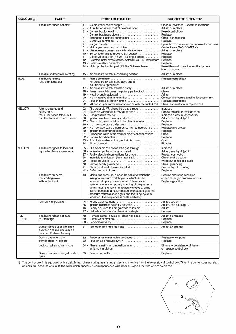
39
(1) The control box 1) is equipped with a disk 2) that rotates during the starting phase and is visible from the lower side of control box. When the burner does not start,or locks out, because of a fault, the color which appears in correspondance with index 3) signals the kind of inconvenience.
COLOUR (1) FAULT PROBABLE CAUSE SUGGESTED REMEDY
The burner does not start 1 - No electrical power supply . . . . . . . . . . . . . . . . . . . . . . . . .Close all switches - Check connections2 - A limiter or safety control device is open. . . . . . . . . . . . . . .Adjust or replace3 - Control box lock-out . . . . . . . . . . . . . . . . . . . . . . . . . . . . . .Reset control box4 - Control box fuses blown . . . . . . . . . . . . . . . . . . . . . . . . . . .Replace5 - Erroneous electrical connections . . . . . . . . . . . . . . . . . . . .Check connections6 - Defective control box . . . . . . . . . . . . . . . . . . . . . . . . . . . . . .Replace7 - No gas supply. . . . . . . . . . . . . . . . . . . . . . . . . . . . . . . . . . . . . . . Open the manual valves between meter and train 8 - Mains gas pressure insufÞcient . . . . . . . . . . . . . . . . . . . . . .Contact your GAS COMPANY9 - Minimum gas pressure switch fails to close . . . . . . . . . . . .Adjust or replace10 - Servomotor fails to move to St1 position . . . . . . . . . . . . . . .Replace11 - Defective capacitor (RS 28 - 38 single-phase) . . . . . . . . . .Replace12 - Defective motor remote control switch (RS 38 - 50 three-phase).Replace13 - Defective electrical motor . . . . . . . . . . . . . . . . . . . . . . . . . .Replace14 - Motor protection tripped (RS 38 - 50 three-phase). . . . . . . . .Reset thermal cut-out when third phase
is re-connected
The disk 2) keeps on rotating 15 - Air pressure switch in operating position Adjust or replace
BLUE The burner starts and then locks out
16 - Flame simulation . . . . . . . . . . . . . . . . . . . . . . . . . . . . . . . . .Replace control boxAir pressure switch inoperative due toinsufÞcient air pressure:
17 - Air pressure switch adjusted badly . . . . . . . . . . . . . . . . . . .Adjust or replace18 - Pressure switch pressure point pipe blocked . . . . . . . . . . .Clean19 - Head wrongly adjusted . . . . . . . . . . . . . . . . . . . . . . . . . . . .Adjust20 - High negative draft in chamber . . . . . . . . . . . . . . . . . . . . . . . . . Connect air pressure switch to fan suction inlet21 - Fault in ßame detection circuit . . . . . . . . . . . . . . . . . . . . . . .Replace control box22 - VS and VR gas valves unconnected or with interrupted coil . .Check connections or replace coil
YELLOW After pre-purge and safety time,the burner goes tolock-outand the ßame does not appear
23 - The solenoid VR allows little gas through . . . . . . . . . . . . . . Increase24 - Solenoid valves VR or VS fail to open . . . . . . . . . . . . . . . . .Renew the coil or rectiÞer panel25 - Gas pressure too low . . . . . . . . . . . . . . . . . . . . . . . . . . . . . Increase pressure at governor26 - Ignition electrode wrongly adjusted. . . . . . . . . . . . . . . . . . .Adjust, see Þg. (C)p.1227 - Electrode grounded due to brocken insulation . . . . . . . . . .Replace28 - High voltage cable defective . . . . . . . . . . . . . . . . . . . . . . . .Replace29 - High voltage cable deformed by high temperature . . . . . . .Replace and protect30 - Ignition trasformer defective . . . . . . . . . . . . . . . . . . . . . . . .Replace31 - Erroneous valve or trasformer electrical connections . . . . .Check32 - Control box defective. . . . . . . . . . . . . . . . . . . . . . . . . . . . . .Replace33 - A cock down-line of the gas train is closed . . . . . . . . . . . . .Open34 - Air in pipework. . . . . . . . . . . . . . . . . . . . . . . . . . . . . . . . . . .Bleed air
YELLOW The burner goes to lock-outright after ßame appearance
35 - The solenoid VR allows little gas through . . . . . . . . . . . . . . Increase36 - Ionisation probe wrongly adjusted. . . . . . . . . . . . . . . . . . . .Adjust, see Þg. (C)p.1237 - Faulty electrical connections for probe . . . . . . . . . . . . . . . .Repeat connection38 - InsufÞcient ionisation (less than 5 mA). . . . . . . . . . . . . . . . .Check probe position39 - Probe grounded . . . . . . . . . . . . . . . . . . . . . . . . . . . . . . . . .Withdraw or replace cable40 - Burner poorly grounded . . . . . . . . . . . . . . . . . . . . . . . . . . .Check grounding41 - Phase and neutral wires inverted . . . . . . . . . . . . . . . . . . . .Correct by interventing42 - Defective control box . . . . . . . . . . . . . . . . . . . . . . . . . . . . . .Replace
The burner repeatsthe starting cyclewithout lock out
43 - Mains gas pressure is near the value to which the . . . . . . .Reduce operating pressuremin. gas pressure switch gas is adjusted. The of minimum gas pressure switch.repeated drop in pressure which follows valve Replace gas Þlteropening causes temporary opening of the pressure switch itself, the valve immediately closes and the burner comes to a halt. Pressure increases again, the pressure switch closes again and the Þring cycle isrepeated. The sequence repeats endlessly.
Ignition with pulsation 44 - Poorly adjusted head. . . . . . . . . . . . . . . . . . . . . . . . . . . . . .Adjust, see p.1445 - Ignition electrode wrongly adjusted. . . . . . . . . . . . . . . . . . .Adjust, see Þg. (C)p.1246 - Poorly adjusted fan air gate: too much air . . . . . . . . . . . . . .Adjust47 - Output during ignition phase is too high . . . . . . . . . . . . . . .Reduce
REDGREEN
The burner does not passto 2nd stage
48 - Remote control device TR does not close. . . . . . . . . . . . . .Adjust oe replace49 - Defective control box . . . . . . . . . . . . . . . . . . . . . . . . . . . . . .Replace50 - Servomotor faulty . . . . . . . . . . . . . . . . . . . . . . . . . . . . . . . .Replace
Burner locks out at transitionbetween 1st and 2nd stage orbetween 2nd and 1st stage
51 - Too much air or too little gas . . . . . . . . . . . . . . . . . . . . . . . .Adjust air and gas
During operation, the burner stops in lock out
52 - Probe or ionisation cable grounded . . . . . . . . . . . . . . . . . .Replace worn parts53 - Fault on air pressure switch. . . . . . . . . . . . . . . . . . . . . . . . .Replace
Lock out when burner stops 54 - Flame remains in combustion head . . . . . . . . . . . . . . . . . .Eliminate persistence of ßame or ßame simulation or replace control box
Burner stops with air gate valve open
55 - Sevomotor faulty . . . . . . . . . . . . . . . . . . . . . . . . . . . . . . . . .Replace

40
(1) Le coffret de s�curit� 1) a un disque 2) qui tourne pendant le programme de d�marrage, visible du c�t� inf�rieur du coffret. Lorsque le br�leur ne d�marre pas ous'arr�te, � cause d'une panne, la couleur qui appara�t en correspondance de l'index 3) signale le type de panne.
COULEUR(1) INCONVENIENT CAUSE PROBABLE REMEDE CONSEILLE
Le br�leur ne d�marre pas 1 - Absence de courant �lectrique . . . . . . . . . . . . . . . . . . . . . .Fermer interrupteurs - Contr�ler fusibles2 - Une t�l�commande de limite ou de s�curit� est ouverte . .La r�gler ou la changer3 - Blocage coffret de s�curit� . . . . . . . . . . . . . . . . . . . . . . . . .D�bloquer le coffret4 - Fusible coffret interrompu . . . . . . . . . . . . . . . . . . . . . . . . . .Le remplacer5 - Branchements �lectriques mal faits . . . . . . . . . . . . . . . . . .Les contr�ler6 - Coffret de s�curit� d�fectueux . . . . . . . . . . . . . . . . . . . . . .Le remplacer7 - Le gaz manque. . . . . . . . . . . . . . . . . . . . . . . . . . . . . . . . . . . . . . . . . . . .Ouvrir les vannes manuelles entre compteur et rampe8 - Pression gaz r�seau insufÞsante . . . . . . . . . . . . . . . . . . . .Contacter la SOCIETE DU GAZ9 - Pressostat gaz seuil minimum ne ferme pas . . . . . . . . . . .Le r�gler ou le remplacer10 - Servomoteur ne se place pas en position St1. . . . . . . . . . .Remplacer11 - Condensateur d�fectueux (RS 28 - 38 monophas�) . . . . .Le remplacer12 - T�l�rupteur commande moteur d�fectueux (RS 38-50 triphas�s).Le remplacer13 - Moteur �lectrique d�fectueux . . . . . . . . . . . . . . . . . . . . . . .Le remplacer14 - Blocage moteur (RS 38 - 50 triphas�s). . . . . . . . . . . . . . . . . .D�bloquer le relais thermique au retour des
trois phases
Le disque 2) continue � tourner 15 - Pressostat air en position de fonctionnement . . . . . . . . . .Le r�gler ou le remplacer
BLEU Le br�leur d�marre et se bloque 16 - Simulation de ßamme . . . . . . . . . . . . . . . . . . . . . . . . . . . . .Remplacer le coffret de s�curit�Pressostat air ne commute pas parce que pression airinsufÞsante:
17 - Pressostat air mal r�gl�. . . . . . . . . . . . . . . . . . . . . . . . . . . .Le r�gler ou le remplacer18 - Tube prise pression du pressostat obstru� . . . . . . . . . . . . .Le nettoyer19 - T�te mal r�gl�e . . . . . . . . . . . . . . . . . . . . . . . . . . . . . . . . . .La r�gler20 - Forte d�pression dans le foyer . . . . . . . . . . . . . . . . . . . . . . . . . Raccorder le pressostat air � l'aspiration ventilateur21 - Panne du circuit r�v�lation ßamme . . . . . . . . . . . . . . . . . . .Remplacer le cofferet de s�curit�22 - Vannes gaz VS et VR non branch�es ou bobine interrompue.Contr�ler les branchements ou remplacer la bobine
JAUNE Apr�s la pr�ventilationet le temps de s�curit�,le br�leur se bloquesans apparition de ßamme
23 - Electrovanne VR fait passer peu de gaz . . . . . . . . . . . . . . .Augmenter24 - L'�lectrovanne VR ou VS ne s'ouvre pas . . . . . . . . . . . . . .Remplacer bobinage ou panneau redresseur25 - Pression gaz trop faible . . . . . . . . . . . . . . . . . . . . . . . . . . . .L'augmenter au r�gulateur26 - Electrode d'allumage mal r�gl�e . . . . . . . . . . . . . . . . . . . . .La r�gler, voir Þg. (C)p.1227 - Electrode � la masse suite � rupture de l'isolant. . . . . . . . .La remplacer28 - C�ble haute tension d�fectueux . . . . . . . . . . . . . . . . . . . . .Le remplacer29 - C�ble haute tension d�form� par haute temp�rature . . . . .Le remplacer et le prot�ger30 - Transformateur d'allumage d�fectueux . . . . . . . . . . . . . . . .Le remplacer31 - Branchements �lectriques vannes ou transformateur mal faits Les contr�ler32 - Coffret de s�curit� d�fectueux . . . . . . . . . . . . . . . . . . . . . .Le remplacer33 - Une vanne en amont de la rampe de gaz est ferm�e . . . . .Ouvrir34 - Air dans les conduites . . . . . . . . . . . . . . . . . . . . . . . . . . . . .Purger
JAUNE Le br�leur se bloquetout de suite apr�sl'apparition de la ßamme
35 - Electrovanne VR fait passer peu de gaz . . . . . . . . . . . . . . .Augmenter36 - Sonde d'ionisation mal r�gl�e . . . . . . . . . . . . . . . . . . . . . . .La r�gler, voir Þg. (C)p.1237 - Raccordement �lectrique sonde d�fectueux . . . . . . . . . . . .Effectuer � nouveau le raccordement38 - Ionisation insufÞsante (inf�rieure 5 mA). . . . . . . . . . . . . . . .Contr�ler la position de la sonde39 - Sonde � la masse . . . . . . . . . . . . . . . . . . . . . . . . . . . . . . . .L'�loigner ou remplacer le c�ble40 - La mise � la terre du br�leur n'est pas sufÞsamment efÞcace Revoir la mise � la terre41 - Les branchements de phase et neutre sont invers�s . . . . . Inverser42 - Coffret de s�curit� d�fectueux . . . . . . . . . . . . . . . . . . . . . .Le remplacer
Le br�leur continue � r�p�ter le cycle de d�marrage sans blocage
43 - La pression du gaz de r�seau est proche de la valeur . . . .R�duire la pressionsur laquelle le pressostat gaz seuil minimum est r�gl�. d'intervention duLa chute de pression r�p�t�e qui suit l'ouverture de la pressostat gaz min.vanne provoque l'ouverture temporaire du pressostat, Remplacer cartouche Þltre gaz.la vanne se ferme aussit�t et le br�leur s'arr�te.La pression augmente � nouveau, le pressostat seferme et fait r�p�ter le cycle de d�marrage.Et ainsi de suite.
Allumage par saccades 44 - T�te mal r�gl�e . . . . . . . . . . . . . . . . . . . . . . . . . . . . . . . . . .La r�gler, voir page 1445 - Electrode d'allumage mal r�gl�e . . . . . . . . . . . . . . . . . . . . .La r�gler, voir Þg. (C)p.1246 - Volet ventilateur mal r�gl�, trop d'air . . . . . . . . . . . . . . . . . .Le r�gler47 - Puissance � l'allumage trop �lev�e. . . . . . . . . . . . . . . . . . .La r�duire
ROUGEVERT
Le br�leur ne passe pas � la 2�me allure
48 - T�l�commande TR ne ferme pas . . . . . . . . . . . . . . . . . . . .La r�gler ou la remplacer49 - Coffret de s�curit� d�fectueux . . . . . . . . . . . . . . . . . . . . . .Le remplacer50 - Servomoteur d�fectueux . . . . . . . . . . . . . . . . . . . . . . . . . . .Remplacer
Blocage du br�leur lors du passage entre 1�re et 2�me allure ou entre 2�me et 1�re allure
51 - Trop d'air ou peu de gaz . . . . . . . . . . . . . . . . . . . . . . . . . . .R�gler air et gaz
Au cours du fonctionnement lebr�leur se bloque
52 - Sonde ou c�ble d'ionisation � la masse . . . . . . . . . . . . . . .Remplacer pi�ces endommag�es53 - D�fectueux pressostat d'air . . . . . . . . . . . . . . . . . . . . . . . . .Remplacer
Blocage � l'arr�t du br�leur 52 - Permanence de ßamme dans la t�te de combustion . . . . .Eliminer la permanence de ßammeou simulation de ßamme ou remplacer le coffret de s�curit�
Br�leur arr�t� volet d'air ouvert 53 - Servomoteur d�fectueux . . . . . . . . . . . . . . . . . . . . . . . . . . .Remplacer


R.B.L. Riello Bruciatori Legnago s.p.a.
Via degli Alpini 1
I - 37045 Legnago (VR)
Tel.: +442 / 630111 Fax: +442 / 21980
�nderungen vorbehalten! - Subject modiÞcations - Sous r�serve de modiÞcations