
Forced draught gas burners€¦ · Forced draught gas burners Modulating operation CODE MODEL TYPE...
56
Installation, use and maintenance instructions 20041904 (9) - 12/2014 Forced draught gas burners Modulating operation CODE MODEL TYPE 3898320 - 3898330 RS 300/E BLU 849T1 3898422 - 3898432 RS 400/E BLU 850T1 3899120 - 3899130 RS 500/E BLU 856T1 20040218 RS 650/E BLU 1123T1 3911020 - 3911030 RS 800/E BLU 887T1 GB
Transcript of Forced draught gas burners€¦ · Forced draught gas burners Modulating operation CODE MODEL TYPE...

Installation, use and maintenance instructions
Forced draught gas burners
Modulating operation
CODE MODEL TYPE
3898320 - 3898330 RS 300/E BLU 849T1
3898422 - 3898432 RS 400/E BLU 850T1
3899120 - 3899130 RS 500/E BLU 856T1
20040218 RS 650/E BLU 1123T1
3911020 - 3911030 RS 800/E BLU 887T1
GB
20041904 (9) - 12/2014

Translation of the original instructions

Contents
1 Declarations...................................... .......................................................................................................................................... 3
2 Information and general warnings.................. .......................................................................................................................... 4
2.1 Information about the instruction manual .................................................................................................................... 42.1.1 Introduction.................................................................................................................................................................. 42.1.2 General dangers.......................................................................................................................................................... 42.1.3 Other symbols ............................................................................................................................................................. 42.1.4 Delivery of the system and the instruction manual...................................................................................................... 5
2.2 Guarantee and responsibility....................................................................................................................................... 5
3 Safety and prevention.............................. .................................................................................................................................. 6
3.1 Introduction.................................................................................................................................................................. 6
3.2 Personnel training ....................................................................................................................................................... 6
4 Technical description of the burner ............... .......................................................................................................................... 7
4.1 Burner designation ...................................................................................................................................................... 7
4.2 Models available.......................................................................................................................................................... 7
4.3 Burner categories - Countries of destination ............................................................................................................... 8
4.4 Technical data ............................................................................................................................................................. 8
4.5 Electrical data.............................................................................................................................................................. 9
4.6 Maximum dimensions................................................................................................................................................ 10
4.7 Firing rates ................................................................................................................................................................ 11
4.8 Test boiler.................................................................................................................................................................. 12
4.9 Burner equipment...................................................................................................................................................... 12
4.10 Burner description ..................................................................................................................................................... 13
4.11 Electrical panel description........................................................................................................................................ 14
4.12 Control box for the air/fuel ratio (LMV51...) ............................................................................................................... 15
4.13 Servomotor (SQM48.4....) ......................................................................................................................................... 17
5 Installation ...................................... .......................................................................................................................................... 18
5.1 Notes on safety for the installation ............................................................................................................................ 18
5.2 Handling .................................................................................................................................................................... 18
5.3 Preliminary checks .................................................................................................................................................... 18
5.4 Operating position ..................................................................................................................................................... 19
5.5 Removal of the locking screws from the shutter........................................................................................................ 19
5.6 Preparing the boiler ................................................................................................................................................... 195.6.1 Boring the boiler plate ............................................................................................................................................... 195.6.2 Blast tube length........................................................................................................................................................ 19
5.7 Securing the burner to the boiler ............................................................................................................................... 20
5.8 Access to head internal part...................................................................................................................................... 20
5.9 Probe-electrode position ........................................................................................................................................... 20
5.10 Combustion head adjustment.................................................................................................................................... 21
5.11 Gas feeding ............................................................................................................................................................... 235.11.1 Gas feeding line ........................................................................................................................................................ 235.11.2 Gas train.................................................................................................................................................................... 245.11.3 Gas train installation.................................................................................................................................................. 245.11.4 Gas pressure............................................................................................................................................................. 25
5.12 Electrical wiring ......................................................................................................................................................... 265.12.1 Supply cables and external connections passage .................................................................................................... 26
6 Start-up, calibration and operation of the burner .. ............................................................................................................... 27
6.1 Notes on safety for the first start-up .......................................................................................................................... 27
6.2 Adjustments prior to ignition ...................................................................................................................................... 27
6.3 Burner start-up .......................................................................................................................................................... 27
6.4 Burner ignition ........................................................................................................................................................... 27
6.5 Combustion air adjustment........................................................................................................................................ 28
1 20041904GB

Contents
6.5.1 Air adjustment for maximum output ...........................................................................................................................286.5.2 Air/fuel adjustment and output modulation system ....................................................................................................28
6.6 Pressure switch adjustment .......................................................................................................................................296.6.1 Air pressure switch - check CO..................................................................................................................................296.6.2 Maximum gas pressure switch...................................................................................................................................296.6.3 Minimum gas pressure switch....................................................................................................................................29
7 Maintenance ....................................... .......................................................................................................................................30
7.1 Notes on safety for the maintenance .........................................................................................................................30
7.2 Maintenance programme ...........................................................................................................................................307.2.1 Maintenance frequency..............................................................................................................................................307.2.2 Checking and cleaning...............................................................................................................................................30
7.3 Opening the burner ....................................................................................................................................................31
7.4 Closing the burner......................................................................................................................................................31
8 Faults - Probable causes - Solutions ................ ......................................................................................................................32
A Appendix - Accessories ............................ ...............................................................................................................................33
B Appendix - Electrical panel layout................. ..........................................................................................................................35
20041904 2 GB

Declarations
1 Declarations
Declaration of conformity in accordance with ISO / I EC 17050-1
Manufacturer: RIELLO S.p.A.
Address: Via Pilade Riello, 737045 Legnago (VR)
Product: Forced draught gas burners
Model: RS 300/E BLURS 400/E BLURS 500/E BLURS 650/E BLURS 800/E BLU
These products are in compliance with the following Technical Standards:
EN 676
EN 12100
and according to the European Directives:
GAD 2009/142/EC Gas Devices Directive
MD 2006/42/EC Machine Directive
LVD 2006/95/EC Low Voltage Directive
EMC 2004/108/EC Electromagnetic Compatibility
Such products are marked as follows:
EC-0085BO0341 RS 300-400-500/E BLU
EC-0085BT0337 RS 650/E BLU
EC-0085BT0337 RS 800/E BLU
The quality is guaranteed by a quality and manageme nt system certified in accordance with UNI EN ISO 90 01.
Manufacturer's Declaration
RIELLO S.p.A. declares that the following products comply with the NOx emission limits specified by German standard “1. BIm-SchV revision 26.01.2010 ”.
Product Type Model Output
Forced draught gas burners 849T1 RS 300/E BLU 500 - 3800 kW850T1 RS 400/E BLU 800 - 4550 kW856T1 RS 500/E BLU 1000 - 5170 kW1123T1 RS 650/E BLU 1400 - 6500 kW887T1 RS 800/E BLU 1200 - 8100 kW
Legnago, 03.09.2014 Executive General ManagerRIELLO S.p.A. - Burner Department
Research & Development DirectorRIELLO S.p.A. - Burner Department
Mr. U. Ferretti Mr. R. Cattaneo
3 20041904GB

Information and general warnings
2.1 Information about the instruction manual
2.1.1 IntroductionThe instruction manual supplied with the burner:➤ is an integral and essential part of the product and must not
be separated from it; it must therefore be kept carefully forany necessary consultation and must accompany the burnereven if it is transferred to another owner or user, or toanother system. If the manual is lost or damaged, anothercopy must be requested from the Technical Assistance Ser-vice of the area;
➤ is designed for use by qualified personnel;➤ offers important indications and instructions relating to the
installation safety, start-up, use and maintenance of theburner.
Symbols used in the manual
In some parts of the manual you will see triangular DANGERsigns. Pay great attention to these, as they indicate a situation ofpotential danger.
2.1.2 General dangersThe dangers can be of 3 levels , as indicated below.
2.1.3 Other symbols
Abbreviations used
Ch. ChapterFig. FigurePage PageSec. SectionTab. Table
2 Information and general warnings
DANGER
Maximum danger level!This symbol indicates operations which, if not car-ried out correctly, cause serious injury, death orlong-term health risks.
WARNING
This symbol indicates operations which, if not car-ried out correctly, may cause serious injury, deathor long-term health risks.
CAUTION
This symbol indicates operations which, if not car-ried out correctly, may cause damage to the ma-chine and/or injury to people.
DANGER
DANGER: LIVE COMPONENTS
This symbol indicates operations which, if not car-ried out correctly, lead to electric shocks with le-thal consequences.
DANGER: FLAMMABLE MATERIAL
This symbol indicates the presence of flammablematerials.
DANGER: BURNING
This symbol indicates the risks of burns due tohigh temperatures.
DANGER: CRUSHING OF LIMBS
This symbol indicates the presence of movingparts: danger of crushing of limbs.
WARNING: MOVING PARTS
This symbol indicates that you must keep limbsaway from moving mechanical parts; danger ofcrushing.
DANGER: EXPLOSION
This symbol signals places where an explosive at-mosphere may be present. An explosive atmos-phere is defined as a mixture - under atmosphericconditions - of air and flammable substances inthe form of gases, vapours, mist or dust in which,after ignition has occurred, combustion spreads tothe entire unburned mixture.
PERSONAL PROTECTION EQUIPMENT
These symbols indicate the equipment that mustbe worn and kept by the operator for protectionagainst threats against safety and/or health whileat work.
OBLIGATION TO ASSEMBLE THE HOOD ANDALL THE SAFETY AND PROTECTION DEVIC-ES
This symbol signals the obligation to reassemblethe hood and all the safety and protection devicesof the burner after any maintenance, cleaning orchecking operations.
ENVIRONMENTAL PROTECTION
This symbol gives indications for the use of themachine with respect for the environment.
IMPORTANT INFORMATION
This symbol indicates important information thatyou must bear in mind.
➤ This symbol indicates a list.
20041904 4 GB

Information and general warnings
2.1.4 Delivery of the system and the instruction manual
When the system is delivered, it is important that:➤ the instruction manual is delivered to the user by the system
manufacturer, with the recommendation to keep it in theroom where the heat generator is to be installed.
➤ The instruction manual shows:– the serial number of the burner;
– the address and telephone number of the nearest Assis-tance Centre.
➤ The system supplier must carefully inform the user about:– the use of the system; – any further tests that may be required before activating the
system; – maintenance, and the need to have the system checked at
least once a year by a representative of the manufactureror another specialised technician.To ensure a periodic check, the manufacturer recom-mends the drawing up of a Maintenance Contract.
2.2 Guarantee and responsibility
The manufacturer guarantees its new products from the installa-tion date, in accordance with the regulations in force and/or thesales contract. At the moment of the first start-up, check that theburner is integral and complete.
In particular, the rights to the guarantee and the responsibility willno longer be valid, in the event of damage to things or injury topeople, if such damage/injury was due to any of the followingcauses:➤ incorrect installation, start-up, use and maintenance of the
burner;➤ improper, incorrect or unreasonable use of the burner;➤ intervention of unqualified personnel;➤ carrying out of unauthorised modifications on the equipment;➤ use of the burner with safety devices that are faulty, incor-
rectly applied and/or not working;➤ installation of untested supplementary components on the
burner;➤ powering of the burner with unsuitable fuels;➤ faults in the fuel supply system;➤ use of the burner even following an error and/or an irregular-
ity;➤ repairs and/or overhauls incorrectly carried out;➤ modification of the combustion chamber with inserts that
prevent the regular development of the structurally estab-lished flame;
➤ insufficient and inappropriate surveillance and care of thoseburner components most likely to be subject to wear andtear;
➤ the use of non-original components, including spare parts,kits, accessories and optional;
➤ force majeure.
The manufacturer furthermore declines any and every re-sponsibility for the failure to observe the content s of thismanual.
.........................................................................................
.........................................................................................
.........................................................................................
.........................................................................................
WARNING
Failure to observe the information given in thismanual, operating negligence, incorrect installa-tion and carrying out of non authorised modifica-tions will result in the annulment by themanufacturer of the guarantee that it supplies withthe burner.
5 20041904GB

Safety and prevention
3.1 Introduction
The burners have been designed and built in compliance withcurrent regulations and directives, applying the known technicalrules of safety and envisaging all the potential danger situations.
It is necessary, however, to bear in mind that the imprudent andclumsy use of the equipment may lead to situations of death riskfor the user or third parties, as well as the damaging of the burneror other items. Inattention, thoughtlessness and excessive confi-dence often cause accidents; the same applies to tiredness andsleepiness.
It is a good idea to remember the following:➤ The burner must only be used as expressly described. Any
other use should be considered improper and therefore dan-gerous.
In particular:
it can be applied to boilers operating with water, steam, diather-mic oil, and to other users expressly named by the manufacturer;
the type and pressure of the fuel, the voltage and frequency of theelectrical power supply, the minimum and maximum deliveries forwhich the burner has been regulated, the pressurisation of thecombustion chamber, the dimensions of the combustion cham-ber and the room temperature must all be within the values indi-cated in the instruction manual.➤ Modification of the burner to alter its performance and desti-
nations is not allowed.➤ The burner must be used in exemplary technical safety con-
ditions. Any disturbances that could compromise safety mustbe quickly eliminated.
➤ Opening or tampering with the burner components is notallowed, apart from the parts requiring maintenance.
➤ Only those parts envisaged by the manufacturer can bereplaced.
3.2 Personnel training
The user is the person, body or company that has acquired themachine and intends to use it for the specific purpose. He is re-sponsible for the machine and for the training of the people work-ing around it.
The user:➤ undertakes to entrust the machine exclusively to suitably
trained and qualified personnel;➤ undertakes to inform his personnel in a suitable way about
the application and observance of the safety instructions.With that aim, he undertakes to ensure that everyone knowsthe use and safety instructions for his own duties;
➤ Personnel must observe all the danger and caution indica-tions shown on the machine.
➤ Personnel must not carry out, on their own initiative, opera-tions or interventions that are not within their province.
➤ Personnel must inform their superiors of every problem ordangerous situation that may arise.
➤ The assembly of parts of other makes, or any modifications,can alter the characteristics of the machine and hence com-promise operating safety. The manufacturer thereforedeclines any and every responsibility for any damage thatmay be caused by the use of non-original parts.
In addition:
3 Safety and prevention
WARNING
The manufacturer guarantees safety and properfunctioning only if all burner components are intactand positioned correctly.
➤ the user must take all the measures neces-sary to prevent unauthorised people gainingaccess to the machine;
➤ the user must inform the manufacturer iffaults or malfunctioning of the accident pre-vention systems are noticed, along with anypresumed danger situation;
➤ personnel must always use the personal pro-tective equipment envisaged by legislationand follow the indications given in this man-ual.
20041904 6 GB

Technical description of the burner
4.1 Burner designation
4.2 Models available
Tab. A
4 Technical description of the burner
Designation Voltage Start-up Code
RS 300/E BLU 3/400/50 Direct 3898320 - 3898330
RS 400/E BLU 3/400/50 Star/Delta 3898422 - 3898432
RS 500/E BLU 3/400/50 Star/Delta 3899120 - 3899130
RS 650/E BLU 3/400/50 Star/Delta 20040218
RS 800/E BLU 3/400/50 Star/Delta 3911020 - 3911030
Class 3 EN267 - Class 3 EN676
Range: R
Size
Fuel: Natural gas
Light oil
Light oil / Methane
Adjustment:
Flame control system:FS1FS2
Standard (1 stop every 24h)Continuous operation (1 stop every 72h)
Electrical supply of the system:3/400/503/230/50
Voltage of auxiliaries:230/50/60110/50/60
R S 300 E TC
Emission: C11 or... Class 1 EN267 - EN676C11 or MZ Class 2 EN267 - EN676
C33 or BLU Class 3 EN267 - EN676
FS1 3/400/50 230/50/60
BASIC DESIGNATION
EXTENDED DESIGNATION
BLU
3N / 400V / 50Hz3 / 230V / 50Hz
230V / 50-60Hz110V / 50-60Hz
Heavy oil
E Electronic camEV Electronic cam with variable speed (with Inverter)P Proportional air/gas valve
BP Two stage (light oil) / Proportional valve (gas)
M Mechanical cam
S
L
LS
N
Head: TC Standard headTL Long head
C11 or...
C13 Class 1 EN267 - Class 3 EN676
7 20041904GB

Technical description of the burner
4.3 Burner categories - Countries of destination
Tab. B
4.4 Technical data
Tab. C
Tab. D(1) Reference conditions: Ambient temperature 20°C - Gas temperature 15°C - Barometric pressure 1013 mbar - Altitude 0 m a.s.l.
(2) Pressure at the test point of the pressure switch (20)(Fig. 4) with zero pressure in the combustion chamber and at maximum burner output.
(3) Sound pressure measured in manufacturer's combustion laboratory, with burner operating on test boiler and at maximum rated output. The soundpower is evaluated, in line with the regulations, on a spherical surface centred on the burner and with a radius of 1 metre.
Gas category Destination countryI2H SE - FI - AT - GR - DK - ES - GB - IT - IE - PT - IS - CH - NO
I2ELL DEI2L NLI2Er FR
I2E(R)B BEI2E LU - PL
Model RS 300/E BLU RS 400/E BLU RS 500/E BLU
Output (1)Output (1)
min - max kW 500/1350 ÷ 3800 800/1840 ÷ 4550 1000/2500 ÷ 5170
Fuels Natural gas: G20 (methane gas) - G21 - G22 - G23 - G25
Gas pressure at max. output (2) - Gas: G20/G25
mbar 23.3/32.7 34.3/40.2 37.6/56.1
Operation Continuous / Intermittent (min. 1 stop in 24 hours)
Standard applications Boilers: water, steam, diathermic oil
Ambient temperature °C 0 - 50
Combustion air temperature °C max 60
Noise levels (3) Sound pressureSound power
dB(A)8293
8596
8899
Weight kg 225 236 250
Model RS 650/E BLU RS 800/E BLU
Output (1)Output (1)
min - max kW 1410/3020 ÷ 6500 1200/3500 ÷ 8100
Fuels Natural gas: G20 (methane gas) - G21 - G22 - G23 - G25
Gas pressure at max. output (2) - Gas: G20/G25
mbar 44.8/64.4 45.5/81.2
Operation Continuous / Intermittent (min. 1 stop in 24 hours)
Standard applications Boilers: water, steam, diathermic oil
Ambient temperature °C 0 - 50
Combustion air temperature °C max 60
Noise levels (3) Sound pressureSound power
dB(A)90.1101.1
88.199.1
Weight kg 300 300
20041904 8 GB

Technical description of the burner
4.5 Electrical data
Tab. E
Tab. F
Tab. G
Tab. H
Model RS 300/E BLU RS 400/E BLU RS 500/E BLU
Main electrical supply 3N ~ 400V +/-10% 50 Hz
Fan motor IE2
rpmV
kWA
2880230/400
4.515/8.7
2900400/690
7.513.8/8
2920400/690
9.216.9/9.7
Ignition transformerV1 - V2I1 - I2
230 V - 1 x 8 kV1 A - 20 mA
Absorbed electrical power kW max 6 9.2 10.8
Protection level IP 54
Model RS 650/E BLU RS 800/E BLU
Main electrical supply 3N ~ 400V +/-10% 50 Hz
Fan motor IE2
rpmV
kWA
2940400/690
18.535.7/20.6
2880400/690
2241.8/24.2
Ignition transformerV1 - V2I1 - I2
230 V - 1 x 8 kV1 A - 20 mA
Absorbed electrical power kW max 20.8 24.5
Protection level IP 54
Model RS 400/E BLU RS 500/E BLU
Main electrical supply 3N ~ 400V +/-10% 50 Hz
Fan motor IE3
rpmV
kWA
2920400/690
7.514/8.1
2880400/690
9.216.8/9.7
Ignition transformerV1 - V2I1 - I2
230 V - 1 x 8 kV1 A - 20 mA
Absorbed electrical power kW max 8.8 10.6
Protection level IP 54
Model RS 650/E BLU RS 800/E BLU
Main electrical supply 3N ~ 400V +/-10% 50 Hz
Fan motor IE3
rpmV
kWA
2880400/690
18.532.2/18.6
2880400/690
2238.2/22.3
Ignition transformerV1 - V2I1 - I2
230 V - 1 x 8 kV1 A - 20 mA
Absorbed electrical power kW max 20.5 24
Protection level IP 54
9 20041904GB

Technical description of the burner
4.6 Maximum dimensions
The maximum dimensions of the burner are shown in Fig. 1.
Bear in mind that inspection of the combustion head requires theburner to be opened and the rear part turned on the hinge.
The maximum dimensions of the open burner are indicated bythe L and R positions.
The l position is reference for the refractory thickness of the boilerdoor.
Tab. I
Fig. 1
20065560
mm A B C D E F G H I L R
RS 300/E BLU 1325 521 164 313 588 DN65 720 867 373 1175 1055
RS 400/E BLU 1325 521 164 313 588 DN65 775 867 373 1175 1055
RS 500/E BLU 1325 521 164 370 588 DN65 775 867 357 1175 1055
RS 650/E BLU 1325 549 164 363 588 DN80 835 867 397 1175 1055
RS 800/E BLU 1325 582 164 363 588 DN80 835 867 418 1175 1055
20041904 10 GB

Technical description of the burner
4.7 Firing rates
The MAXIMUM OUTPUT is chosen from within the diagram area(Fig. 2).
The MINIMUM OUTPUT must not be lower than the minimumlimit of the diagram:
Model kWRS 300/E BLU 500RS 400/E BLU 800RS 500/E BLU 1000
RS 650/E BLU 1400RS 800/E BLU 1200
WARNING
The firing rate value (Fig. 2) has been obtainedconsidering an ambient temperature of 20C, anatmospheric pressure of 1013 mbar (approx. 0 ma.s.l.), and with the combustion head adjusted asshown on page 21.
Thermal power – kW
400 800 1200 1600 2000 2400 2800 3200 3600 4000 4400 4800 0
2
4
6
8
10
12
14
16
68006400600056005200
18
400 1200 2000 2800 3600 44000
2
4
6
8
10
12
14
16
18
20
mba
r
22
24
5200 6000 6800 7600 8400
25
26
Fig. 2
Thermal power – kW
RS 400/E
RS 300/E
Com
bust
ion
cham
ber
pres
sure
- m
bar
RS 500/E
RS 800/E
D8128
RS 650/E
D11730
Com
bust
ion
cham
ber
pres
sure
- m
bar
11 20041904GB
Technical description of the burner
4.8 Test boiler
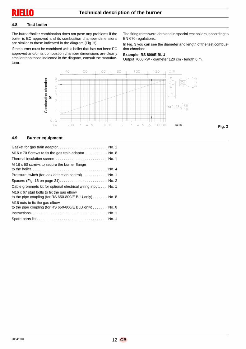
The burner/boiler combination does not pose any problems if theboiler is EC approved and its combustion chamber dimensionsare similar to those indicated in the diagram (Fig. 3).
If the burner must be combined with a boiler that has not been ECapproved and/or its combustion chamber dimensions are clearlysmaller than those indicated in the diagram, consult the manufac-turer.
The firing rates were obtained in special test boilers, according toEN 676 regulations.
In Fig. 3 you can see the diameter and length of the test combus-tion chamber.
Example: RS 800/E BLUOutput 7000 kW - diameter 120 cm - length 6 m.
4.9 Burner equipment
Gasket for gas train adaptor. . . . . . . . . . . . . . . . . . . . . . . . No. 1
M16 x 70 Screws to fix the gas train adaptor . . . . . . . . . . . No. 8
Thermal insulation screen . . . . . . . . . . . . . . . . . . . . . . . . . No. 1
M 18 x 60 screws to secure the burner flange to the boiler . . . . . . . . . . . . . . . . . . . . . . . . . . . . . . . . . . . . No. 4
Pressure switch (for leak detection control) . . . . . . . . . . . . No. 1
Spacers (Fig. 16 on page 21). . . . . . . . . . . . . . . . . . . . . . . No. 2
Cable grommets kit for optional electrical wiring input . . . . No. 1
M16 x 67 stud bolts to fix the gas elbow to the pipe coupling (for RS 650-800/E BLU only) . . . . . . . No. 8
M16 nuts to fix the gas elbow to the pipe coupling (for RS 650-800/E BLU only) . . . . . . . No. 8
Instructions. . . . . . . . . . . . . . . . . . . . . . . . . . . . . . . . . . . . . No. 1
Spare parts list . . . . . . . . . . . . . . . . . . . . . . . . . . . . . . . . . . No. 1
Fig. 3
Com
bust
ion
cham
ber
M
D2448
20041904 12 GB

Technical description of the burner
4.10 Burner description
1 Lifting rings2 Fan3 Fan motor4 Air damper servomotor5 Combustion head gas pressure test point6 Combustion head7 Ignition electrode8 Flame stability disc9 Electrical panel casing10 Gas butterfly valve servomotor11 Fan air inlet12 Pipe coupling13 Gasket for boiler fixing14 Gas butterfly valve15 Shutter16 Combustion head movement lever17 Air damper movement gears18 Air pressure switch (differential operating type)19 Combustion head air pressure test point
20 Maximum gas pressure switch with pressure test point21 Flame sensor probe22 Hinge for opening the burner23 Pressure test point for air pressure switch “+”24 Pressure test point for air pressure switch “-”
Fig. 420065595
CAUTION
The burner can be opened to the right or to the leftwithout links to the fuel supply side.
When the burner is closed, the hinge can be refit-ted on the opposite side.
13 20041904GB

Technical description of the burner
4.11 Electrical panel description
1 Terminal board for kits2 Volt-free contacts output relay3 Electronic cam transformer4 Calibration device with electronic cam5 Ignition transformer6 Bracket for application of output power Regulator kit RWF407 Stop push-button8 OFF-automatic-manual selector9 Power increase - power reduction selector10 Light signalling of mains live state11 Fan motor lock-out warning lamp12 Light signalling of burner lockout and reset switch13 AZL kit support14 Star-triangle starter (except for RS 300/E BLU)15 Timer (except for RS 300/E BLU)16 Air pressure switch17 Main terminal supply board18 Supply cables and external connections passage19 Thermal relay
NOTE
Two types of burner lockout may occur:➤ Flame control lockout: if the pilot light 12)(Fig. 5) on the
panel lights up, it indicates that the burner is in lockout.release by pressing the pushbutton 12)(Fig. 5).
➤ Motor lockout: release by pressing the button on thermalrelay.
Fig. 5
20081364
RS 300/E BLU RS 650/E BLURS 800/E BLURS 400/E BLU
RS 500/E BLU
20041904 14 GB

Technical description of the burner
4.12 Control box for the air/fuel ratio (LMV51...)
Warnings
➤ All interventions (assembly and installation operations,assistance, etc.) must be carried out by qualified personnel.
➤ Before modifying the wiring in the LMV52 control box con-nection area, fully disconnect the system from the powersupply (omnipolar separation). Check the system is not pow-ered and cannot be accidentally reconnected. Failure to dothis will lead to the risk of electrocution.
➤ Protection against electrocution from the LMV5... control boxand all connected electric components is obtained with cor-rect assembly.
➤ Before any intervention (assembly and installation opera-tions, assistance, etc.), ensure the wiring is in order and thatthe parameters are correctly set, then make the safetychecks.
➤ Falls and collisions can negatively affect the safety func-tions. In this case, the control box must not be operated, even if itdisplays no evident damage.
➤ In programming mode, the position check of actuators andVSD (checking electronic fuel / air ratio control) is differentfrom the check during automatic operation.As for automatic operation, the actuators are guidedtogether to the positions requested and, if an actuator doesnot reach the position requested, adjustments are made untilthe position is actually reached. However, in contrast toautomatic operation, there are no time limits to these correc-tive actions. The other actuators maintain their positions until all actua-tors have reached the positions currently required. This is absolutely important to set the fuel / air ratio controlsystem. During the time the fuel / air ratio curves are being pro-grammed, the person making the plant settings must continu-ously monitor the quality of the combustion process (e.g. bymeans of a flue gas analyzer). Also, if combustion levels are poor, or in the event of danger-ous situations, the commissioning engineer must takeappropriate action (e.g. switching off manually).
To ensure the safety and reliability of the LMV5... system, thefollowing instructions must also be followed:– avoid conditions that can favour the development of conden-
sate and humidity. Otherwise, before switching on again,make sure that the entire control box is perfectly dry!
– Static charges must be avoided since they can damage thecontrol box’s electronic components when touched.
Mechanical structureThe LMV5... control box is a system to check the burners, basedon a microprocessor and equipped with components to adjustand monitor medium and large capacity forced draught burners.The base control box of the LMV5... system incorporates the fol-lowing components:
• Burner control with gas valve proving system
• Electronic fuel / air ratio control with a maximum of 4 (LMV51…) or 6 (LMV52…) actuators
• Optional PID temperature / pressure controller (load controller)
• Optional VSD module Mechanical design
Installation notes
• Check the electric wiring inside the boiler complies with the na-tional and local safety regulations.
• Do not confuse the powered conductors with the neutral ones.
• Make certain that strain relief of the connected cables is incompliance with the relevant standards (e.g. as per DIN EN60730 and DIN EN 60 335).
• Ensure that spliced wires cannot get into contact with neigh-boring terminals. Use adequate ferrules.
• Arrange the HV ignition cables separately, as far as possiblefrom the control box and the other cables.
• The burner manufacturer must protect unused AC 230 V ter-minals with dummy plugs (refer to sections Suppliers of otheraccessory items).
• When wiring the unit, make sure that AC 230 V mains voltagecables are run strictly separate from extra low-voltage cablesto avoid risks of electrical shock hazard.
WARNING
To avoid accidents, material or environmentaldamage, observe the following instructions!
The LMV51... is a safety device! Avoid opening ormodifying it, or forcing its operation. Riello S.p.A.cannot assume any responsibility for damage re-sulting from unauthorised interventions!
Risk of explosion!
An incorrect configuration can provoke fuel over-charging, with the consequential risk of explosion!Operators must be aware that incorrect settingsmade on the AZL5… display and operating unitand incorrect settings of the fuel and / or air actu-ator positions can lead to dangerous burner oper-ating conditions.
Fig. 6D9301
15 20041904GB

Technical description of the burner
Electrical connection of ionization probe and flame detector
It is important for signal transmission to be almost totally freeof any disturbances or loss:
• always separate the detector cables from the other cables:– Line capacitance reduces the magnitude of the flame signal.– Use a separate cable.
• Respect the allowed cable lengths.
• The ionisation probe is not protected against the risk of elec-trocution. When connected to the electricity supply, the ionisa-tion probe must be protected against any accidental contact.
• Position the ignition electrode and the ionisation probe sothat the ignition spark cannot form an arc on the p robe(risk of electric overcharge).
Technical data
Tab. J
LMV51... basic unit Mains voltage AC 230 V -15 % / +10 %
Mains frequency 50 / 60 Hz ±6 %
Power absorption < 30W (normal)
Safety class I, with components in compliance with II and III, according to DIN EN 60730-1
Load on‘input’ terminals
F1 unit fuse (internal) 6.3 AT
Main fuse of perm. network (external) Max. 16 AT
Undervoltage• Safety switch-off from operating position to
mains voltage• Restart when mains voltage picks up
< AC 186 V
> AC 188 V
Oil pump / magnetic clutch (nominal voltage)• Nominal current• Power factor
2Acosϕ > 0.4
Air pressure switch test valve (nominal voltage)• Nominal current• Power factor
0.5Acosϕ > 0.4
Load on ‘output’terminals
Total load on the contacts:• Mains voltage• Total unit input current (safety circuit)
load on contacts due to:- Fan motor contactor- Ignition transformer- Valve- Oil pump / magnetic clutch
AC 230 V -15 % / +10 %Max. 5 A
Single contact loading:Fan motor contactor (nominal voltage)• Nominal current• Power factor
1A cosϕ > 0.4
Alarm output (nominal voltage)• Nominal current• Power factor
1Acosϕ > 0.4
Ignition transformer (nominal voltage)• Nominal current• Power factor
2A cosϕ > 0.2
Fuel gas valve (nominal voltage)• Nominal current• Power factor
2A cosϕ > 0.4
Fuel oil valve (nominal voltage)• Nominal current• Power factor
1A cosϕ > 0.4
Cable lengths Main line Max. 100 m (100 pF/m)
Environmental conditions
OperationClimatic conditionsMechanical conditionsTemperature rangeHumidity
DIN EN 60721-3-3Class 3K3Class 3M3-20...+60°C< 95% RH
20041904 16 GB

Technical description of the burner
4.13 Servomotor (SQM48.4....)
Warnings
➤ All interventions (assembly and installation operations,assistance, etc.) must be carried out by qualified personnel.
➤ Before modifying the wiring in the SQM4... system connec-tion area, fully disconnect the burner control device from thepower supply (omnipolar separation).
➤ To avoid the risk of electrocution, protect the connection ter-minals in a suitable manner and correctly fix the cover.
➤ Check the wiring is in order.➤ Falls and collisions can negatively affect the safety func-
tions. In this case, the unit must not be operated, even if itdisplays no evident damage.
Assembly notes
• Check the relevant national safety standards are respected.
• The connection between the actuator command shaft and thecontrol element must be rigid, without any mechanical play.
• To avoid an excessive load on the bearings due to rigid hubs,the use of compensation clutches without any mechanicalplay is recommended (e.g. metal bellows-type clutches).
Installation notes
• Arrange the H.V. ignition cables separately, as far as possiblefrom the control box and the other cables.
• To avoid the risk of electrocution, make sure that the 230V ACsection of the SQM4... unit is fully separated from the function-al low-voltage section.
• The static torque is reduced when the electrical supply of theactuator is switched off.
• The housing cover may only be removed for short periods oftime for wiring or when making the addressing. In similar cas-es, make sure that dust or dirt does not penetrate inside theactuator.
• The actuator comprises a PCB with ESD-sensitive compo-nents.
• The top side of the board carries a cover which affords pro-tection against direct contact. This protective cover must notbe removed! The underside side of the board must not betouched.
Technical data
Tab. K
WARNING
To avoid accidents, material or environmen-tal damage, observe the following instruc-tions!
Avoid opening, modifying or forcing the ac-tuators.
WARNING
During the maintenance or replacement of theactuators, be careful not to invert the connec-tors.
Operating voltage AC 2 x 12 V via bus cable from thebase unit or via a separate trans-former
Safety class extra low-voltage with safe isolationfrom mains voltage
Power consumption 26...34 VA
Degree of protection to EN 60 529, IP 54, provided ade-quate cable entries are used
Cable connection RAST3,5 connectors
Rotation direction - Anticlockwise (standard) - Clockwise (inverted rotation)
Nominal torque (max) 20 Nm
Holding torque (max) 20 Nm
Running time (min.) for 90°
30 s.
Weight approx. 1.6 kg
Environmental conditions:
OperationClimatic conditionsMechanical conditionsTemperature rangeHumidity
DIN EN 60 721-3-3Classe 3K3Classe 3M3-20...+60°C< 95% RH
D8271Fig. 7
17 20041904GB

Installation
5.1 Notes on safety for the installation
After carefully cleaning all around the area where the burner willbe installed, and arranging the correct lighting of the environ-ment, proceed with the installation operations.
5.2 Handling
The packaging of the burner includes a wooden platform, so it ispossible to move the burner (still packaged) with a transpallettruck or fork lift truck.
5.3 Preliminary checks
Checking the consignment
Checking the characteristics of the burner
Check the identification label of the burner, showing:➤ the model (A)(Fig. 8) and type of burner (B);➤ the year of manufacture, in cryptographic form (C);➤ the serial number (D);➤ the data for electrical supply and the protection level (E);➤ the absorbed electrical power (F);➤ the types of gas used and the relative supply pressures (G);➤ the data of the burner's minimum and maximum output pos-
sibilities (H) (see Firing rate)Warning. The burner output must be within the boiler's firingrate;
➤ the category of the appliance/countries of destination (I).
5 Installation
DANGER
All the installation, maintenance and disassemblyoperations must be carried out with the electricitysupply disconnected.
WARNING
The installation of the burner must be carried outby qualified personnel, as indicated in this manualand in compliance with the standards and regula-tions of the laws in force.
DANGER
Combustion air inside the boiler must be free fromhazardous mixes (e.g.: chloride, fluoride, halo-gen); if present, it is highly recommended to carryout cleaning and maintenance more frequently.
WARNING
The handling operations for the burner can behighly dangerous if not carried out with the great-est attention: keep any unauthorised people at adistance; check the integrity and suitableness ofthe available means of handling.Check also that the area in which you are workingis empty and that there is an adequate escapearea (i.e. a free, safe area to which you can quick-ly move if the burner should fall).When handling, keep the load at not more than20-25 cm from the ground.
After positioning the burner near the installationpoint, correctly dispose of all residual packaging,separating the various types of material.
CAUTION
Before proceeding with the installation operations,carefully clean all around the area where the burn-er will be installed.
CAUTION
After removing all the packaging, check the integ-rity of the contents. In the event of doubt, do notuse the burner; contact the supplier.
The packaging elements (wooden cage or card-board box, nails, clips, plastic bags, etc.) must notbe abandoned as they are potential sources ofdanger and pollution; they should be collected anddisposed of in the appropriate places.
WARNING
A burner label, or any other component, that hasbeen tampered with, removed or is missing, pre-vents the definite identification of the burner andmakes any installation or maintenance work diffi-cult.
R.B.L.
GAS-KAASUGAZ-AEPIO
X
RIELLO S.p.A.I-37045 Legnago (VR)
AD E
B CF
I
G HG H
Fig. 8D10411
20041904 18 GB

Installation
5.4 Operating position
5.5 Removal of the locking screws from the shutter
5.6 Preparing the boiler
5.6.1 Boring the boiler platePierce the closing plate of the combustion chamber, as in Fig. 11.The position of the threaded holes can be marked using the ther-mal insulation screen supplied with the burner.
5.6.2 Blast tube lengthThe length of the blast tube must be selected according to the in-dications provided by the manufacturer of the boiler, and in anycase it must be greater than the thickness of the boiler door com-plete with its refractory.
For boilers with front flue passes 1) (Fig. 12) or flame inversionchamber, a protection in refractory material 5) must be insertedbetween the boiler fettling 2) and the blast tube 4).
This protection must not compromise the extraction of the blasttube.
For boilers with a water-cooled frontpiece, a refractory lining 2)-5) (Fig. 12) is not necessary, unless expressly requested by theboiler manufacturer.
Tab. L
WARNING
➤ The burner is designed to operate only inpositions 1, 2, 3 and 4 (Fig. 9).
➤ Installation 1 is preferable, as it is the onlyone that allows the maintenance operationsas described in this manual.
➤ Installations 2, 3 and 4 permit operation butmake maintenance and inspection of thecombustion head more difficult.
DANGER
➤ Any other position could compromise the cor-rect operation of the appliance.
➤ Installation 5 is prohibited for safety reasons.
Fig. 9
2 3 4 51
D7739
WARNING
Remove the screws and the nuts 1)-2)(Fig. 10),before installing the burner on the boiler.
Replace them with the screws 3) M12 X 25 sup-plied with the burner.
1
2
1
2
3
3
Fig. 10
D12015
mm A B C
RS 300/E BLU 350 452 M18
RS 400/E BLU 350 452 M18
RS 500/E BLU 390 452 M18
RS 650/E BLU 400 495 M18
RS 800/E BLU 400 495 M18
Fig. 11D455
19 20041904GB

Installation
5.7 Securing the burner to the boiler
➤ Fit the heat insulation supplied onto the blast tube (4)(Fig. 12).
➤ Fit the entire burner onto the boiler hole prepared previously(Fig. 11), and fasten with the screws supplied.
5.8 Access to head internal part
➤ After you have uncoupled the the head movement lever tie-rod 1) and removed the 4 fixing screws 2), open the burneron the hinge (Fig. 13),
➤ Unhook the probe cables and electrode 3).➤ Tighten the underneath part of the elbow 4) until it is
released from its housing.➤ Remove the internal part of the head 5).
5.9 Probe-electrode position
Prepare a suitable lifting system using the rings3)(Fig. 12), after removing the fixing screws 7) ofthe casing 8).
WARNING
The seal between burner and boiler must beairtight.
Fig. 1220065562
Fig. 13
20065578
WARNING
Check that the probe and the electrode are placedas in Fig. 14, according to the dimensions indicat-ed.
4.5
720.5
Fig. 14
ProbeElectrode
D11735
20041904 20 GB

Installation
5.10 Combustion head adjustment
The air damper servomotor 4)(Fig. 4 on page 13), beyond vary-ing the air output according to the output demand, through a lev-erage varies the combustion head adjustment.
This system allows an optimum adjustment also at minimum fir-ing rate.
Similarly to servomotor rotation, it is possible to vary the openingof the combustion head moving the tie-rod on the holes (1-2-3),(Fig. 15).
The selection of the hole (1-2-3) to be used is determined accord-ing to the maximum output requested (Tab. M).
In the factory, the hole is adjusted for the maximum stroke(hole 3).
In case in which, with boilers with high back pressure, also withdamper completely open, the air output is not enough, it is possi-ble to carry out a calibration different to the one indicated by theTab. M, moving the tie-rod on the following higher hole, increas-ing the opening of the combustion head and the air output.
If, for combustion reasons, it is necessary to move the spacer1)(Fig. 16) onto the 1st and 2nd hole of the gear, while the hingeis positioned to the right, the spacers 4) supplied as standardmust be mounted.
Proceed as follows:➤ after you have unscrewed the nuts 2)(Fig. 16), remove the
tie-rod 3), unscrew the spacer 1) and position it in the appro-priate hole;
➤ tighten the spacers 4) to spacer 1) and screw 5) respec-tively;
➤ mount the tie-rod 3) and the nuts 2) again.
Tab. M
Pay attention to moving parts.
Danger of crushing of limbs!
Output (kW) No. Hole
RS
300
/E
1200 1
2200 2
2800 3
3200 3
RS
400
/E
1800 1
3400 2
4000 3
4500 3
RS
500
/E
1000 1
2500 2
3500 3
5200 3
RS
650
/E 1400 2
4700 3
6500 3
RS
800
/E
1800 1
4000 2
6000 3
8100 3
012
3
4
6
3
2
14
Fig. 15D3093
Fig. 16
D3409
21 20041904GB

Installation
WARNING
For RS 300-400-500/E BLU only
In order to work correctly in flame inversion boil-ers, the gas tubes must be adjusted in the hole inposition 4, see Fig. 17.
Fig. 17D3418
20041904 22 GB

Installation
5.11 Gas feeding
5.11.1 Gas feeding lineKey (Fig. 18 - Fig. 19 - Fig. 20 - Fig. 21)
1 Gas input pipe
2 Manual valve
3 Vibration damping joint
4 Pressure gauge with pushbutton cock
5 Filter
6A Includes:– Filter– working valve– safety valve– pressure adjuster
6B Includes:– working valve– safety valve– pressure adjuster
6C Includes– safety valve– working valve
6D Includes:– safety valve– working valve
7 Minimum gas pressure switch
8 Leak detection device, supplied as an accessory or incorpo-rated, based on the gas train code. In compliance with theEN 676 standard, the leak detection control is compulsory forburners with maximum outputs over 1200 kW.
9 Gasket, for “flanged” versions only
10 Pressure adjuster
P2 Upstream pressure of valves/adjuster
P3 Upstream pressure of the filter
L Gas train supplied separately
L1 The responsibility of the installer
Explosion danger due to fuel leaks in the pres-ence of a flammable source.
Precautions: avoid knocking, attrition, sparks andheat.
Make sure that the fuel interception tap is closedbefore performing any operation on the burner.
WARNING
The fuel supply line must be installed by qualifiedpersonnel, in compliance with current standardsand laws.
L1 L
6AP2
7
4
P3
321
8
Fig. 18D11854
MBC “threaded”
Fig. 19
MBC “flanged”
20065706
Fig. 20
DMV “flanged or threaded”
20065609
Fig. 21
CB “flanged or threaded”
20065707
23 20041904GB

Installation
5.11.2 Gas trainType-approved in accordance with EN 676 and supplied sepa-rately from the burner.
To select the correct model of the gas train, refer to the “burner-gas train combination” manual supplied.
5.11.3 Gas train installation
DANGER
Disconnect the electrical power using the mainsystem switch.
Check that there are no gas leaks.
Beware of train movements: danger of crushing oflimbs.
Make sure that the gas train is properly installedby checking for any fuel leaks.
The operator must use appropriate tools for instal-lation.
Fig. 2220065541
20041904 24 GB

Installation
5.11.4 Gas pressureTab. N indicates the minimum pressure drops along the gas sup-ply line, depending on the maximum burner output.
The values shown in Tab. N refer to: – Natural gas G 20 NCV 9.45 kWh/Sm3 (8.2 Mcal/Sm3)– Natural gas G 25 NCV 8.13 kWh/Sm3 (7.0 Mcal/Sm3)
Column 1
Pressure drop on combustion head.Gas pressure measured at the test point P1) (Fig. 22), with:• Combustion chamber at 0 mbar;• Burner working at maximum output;• Combustion head adjusted as in page 21.
Column 2Pressure loss at gas butterfly valve 10) (Fig. 20) with maximumopening: 90°.
Calculate the approximate maximum output of the burner in thisway:– subtract the combustion chamber pressure from the gas
pressure measured at test point P1) (Fig. 22).– Find, in the table Tab. N related to the burner concerned, the
pressure value closest to the result of the subtraction.– read the corresponding output on the left.
Example for RS 650/E BLU with G20 natural gas:Maximum output operationGas pressure at test point P1)(Fig. 22) = 25.6 mbarPressure in combustion chamber = 2 mbar
25.6 - 2 = 23.6 mbar
A pressure of 23.6 mbar, column 1, corresponds in the table Tab.N to an output of 4,500 kW.
This value serves as a rough guide; the effective output must bemeasured at the gas meter.
To calculate the required gas pressure at test point P1) (Fig. 22),set the MAX output required from the burner operation:– find the nearest output value in the table Tab. N for the burner
in question.– read, on the right (column 1), the pressure at the test point
P1)(Fig. 22).– Add this value to the estimated pressure in the combustion
chamber.
Example for RS 650/E BLU with G20 natural gas:Required burner maximum output operation: 4500 kWGas pressure at an output of 4,500 kW = 23.6 mbarPressure in combustion chamber = 2 mbar
23.6 + 2 = 25.6 mbarPressure required at test point P1)(Fig. 22).
Tab. N
kW1 ∆p (mbar) 2 ∆p (mbar)
G 20 G 25 G 20 G 25
RS
300
/E B
LU
1245 7.8 11.6 1.3 2.01500 9.4 13.9 1.9 2.81750 10.9 16.2 2.6 3.92000 12.4 18.5 3.4 5.02250 13.0 19.5 4.3 6.42500 13.7 20.4 5.3 7.92750 14.3 21.4 6.4 9.53000 15.0 22.4 7.6 11.33250 17.6 26.2 8.9 13.33500 20.2 30.1 10.3 15.43800 23.3 34.8 12.2 18.2
RS
400
/E B
LU
1800 6.3 9.3 2.9 4.32000 7.9 11.7 3.5 5.32250 9.9 14.7 4.5 6.72500 11.9 17.7 5.5 8.22750 13.9 20.7 6.7 10.03000 15.9 23.7 8.0 11.93250 17.9 26.7 9.3 13.93500 19,7 29.4 10.8 16.23750 21.1 31.4 12.4 18.64000 22.4 33.5 14.2 21.14250 27.4 40.8 16.0 23.84500 32.5 48.4 17.9 26.7
RS
500
/E B
LU
2500 11.5 17.2 0.6 0.82600 12.3 18.4 0.6 0.92800 13.9 20.8 0.7 1.03000 15.5 23.2 0.8 1.23200 17.1 25.5 0.9 1.43400 18.7 27.9 1.0 1.53600 20.5 30.6 1.2 1.73800 22.5 33.6 1.3 1.94000 24.5 36.6 1.4 2.14200 26.5 39.5 1.6 2.34400 28.5 42.5 1.7 2.64600 30.5 45.5 1.9 2.84800 33.0 49.2 2.0 3.15000 35.5 53.0 2.2 3.35200 38.0 56.7 2.4 3.6
RS
650
/E B
LU
3000 11.0 13.7 1.0 1.53250 13.1 16.7 1.1 1.73500 15.2 19.8 1.3 2.03750 17.3 22.8 1.5 2.34000 19.4 25.8 1.7 2.64250 21.5 28.9 1.9 2.94500 23.6 31.9 2.1 3.34750 25.7 35.1 2.4 3.75000 28.4 39.3 2.6 4.05250 31.2 43.5 2.9 4.55500 33.9 47.7 3.2 4.95750 36.6 51.9 3.5 5.46000 39.3 56.0 3.8 5.86250 42.1 60.2 4.1 6.36500 44.8 64.4 4.5 6.8
RS
800
/E B
LU
3500 9.4 12.8 0.6 0.74000 12.8 17.7 0.7 0.94500 16.2 22.5 0.9 1.15000 19.6 27.3 1.2 1.45500 23.0 32.1 1.4 1.76000 26.4 37.0 1.7 2.06500 30.9 44.7 2.0 2.37000 35.5 52.4 2.3 2.77500 40.9 59.8 2.6 3.18000 46.3 67.1 3.0 3.58060 47.0 68.0 3.0 3.5
25 20041904GB

Installation
5.12 Electrical wiring
Notes on safety for the electrical wiring
Before carrying out any maintenance, cleaning or checking oper-ations:
If the hood is still present, remove it and proceed with the electri-cal wiring according to the wiring diagrams.
Use flexible cables in compliance with the EN 60 335-1 standard.
5.12.1 Supply cables and external connections passage
All the cables to be connected to the burner must be threadedthrough cable grommets. The use of the cable grommets cantake various forms. by way of example see Fig. 23.
Key (Fig. 23)1 Electrical supply2 Fan motor3 minimum gas pressure switch4 Pressure switch kit for PGVP gas valve leak detection5 Gas train6 Consents/Safety7 available8 Connector for external AZL
DANGER
➤ The electrical wiring must be carried out with the electrical supply disconnected.➤ Electrical wiring must be made in accordance with the regulations currently in force in the country of destination
and by qualified personnel. Refer to the wiring diagrams.➤ The manufacturer declines all responsibility for modifications or connections different from those shown in the wir-
ing diagrams➤ Check that the electrical supply of the burner corresponds to that shown on the identification label and in this man-
ual.➤ The burner has been type-approved for continuous use.
This means they should compulsorily be stopped at least once every 72 hours to enable the control box to per-form checks of its own start-up efficiency. Normally, burner stopping is guaranteed by the boiler's thermostat/pres-sure switch.
➤ If this is not the case, a time switch should be fitted in series to TL to stop the burner at least once every 72 hours.Refer to the wiring diagrams.
➤ The electrical safety of the device is obtained only when it is correctly connected to an efficient earthing system,made according to current standards. It is necessary to check this fundamental safety requirement. In the event ofdoubt, have the electrical system checked by qualified personnel. Do not use the gas tubes as an earthing systemfor electrical devices.
➤ The electrical system must be suitable for the maximum power absorption of the device, as indicated on the labeland in the manual, checking in particular that the section of the cables is suitable for that level of power absorp-tion.
➤ For the main power supply of the device from the electricity mains:- do not use adapters, multiple sockets or extensions;- use a multiple pole switch with at least a 3 mm gap between the contacts (overvoltage category III), as envis-
aged by the present safety standards.➤ Do not touch the device with wet or damp body parts and/or in bare feet.➤ Do not pull the electric cables.
DANGER
Disconnect the electrical supply from the burnerby means of the main system switch.
DANGER
Close the fuel interception tap.
DANGER
Avoid condensate, ice and water leaks from form-ing.
After carrying out maintenance, cleaning orchecking operations, reassemble the hood and allthe safety and protection devices of the burner.
7
7
7
7
76
7
6 6 1
1
2 4 3 5 8
6 66
3
24
775
Fig. 23
S8420
RS 300-400-500/E BLU
RS 650-800/E BLU
20041904 26 GB

Start-up, calibration and operation of the burner
6.1 Notes on safety for the first start-up
6.2 Adjustments prior to ignition
Combustion head adjustment is already described on page 21.
In addition, the following adjustments must also be made:➤ open manual valves upline from the gas train.➤ Adjust the minimum gas pressure switch to the start of the
scale.➤ Adjust the maximum gas pressure switch to the end of the
scale.➤ Adjust the air pressure switch to the start of the scale.➤ Purge the air from the gas line.
We recommend using a plastic tube routed outside the build-ing and to purge air until gas is smelt.
➤ Fit a U-type pressure gauge or a differential pressure gauge(Fig. 24), with socket (+) on the gas pressure of the pipecoupling and (-) in the combustion chamber.The manometer readings are used to calculate MAX burneroutput using the Tab. N.
➤ Connect two lamps or testers to the two gas line solenoids tocheck the exact moment in which voltage is supplied. Thisoperation is unnecessary if each of the two solenoids isequipped with a pilot light that signals voltage passingthrough.
6.3 Burner start-up
Close the thermostats/pressure switches and turn the switch 1)(Fig. 25) to position “MAN”.
6.4 Burner ignition
Once the above steps are complete, the burner should light.
If the motor starts up, but the flame does not appear and the con-trol box goes into lockout, reset it and wait for a new ignition at-tempt.
If ignition does not occur, it may be that gas is not reaching thecombustion head within the safety time period of 3 seconds. Inthis case, increase gas ignition delivery.
The arrival of gas at the pipe coupling is indicated by the U-typepressure gauge (Fig. 24).
Once the burner has ignited, proceed with the global adjustmentof the burner.
6 Start-up, calibration and operation of the burner
WARNING
The first start-up of the burner must be carried outby qualified personnel, as indicated in this manualand in compliance with the standards and regula-tions of the laws in force. WARNING
Check the correct working of the adjustment, com-mand and safety devices.
CAUTION
Before starting up the burner, it is good practice toadjust the gas train so that ignition takes place inconditions of maximum safety, i.e. with gas deliv-ery at the minimum.
Fig. 24
20065570
WARNING
Make sure that the lights or testers connected tothe solenoids, or the pilot lights on the solenoidsthemselves, indicate that no voltage is present.
If voltage is present, stop the burner immediatelyand check the electrical wiring.
Fig. 25
0 AUTO MAN - +
D3108
1 2
27 20041904GB

Start-up, calibration and operation of the burner
6.5 Combustion air adjustment
Fuel/combustion air synchronization is done with the relevantservomotors (air and gas) by logging a calibration curve bymeans of the electronic cam.
It is advisable, to reduce the loss and for a wide calibration field,to adjust the servomotors to the maximum of the output used, thenearest possible to the maximum opening (90°).
On the gas butterfly valve, fuel step according to the burner out-put required, with servomotor completely open, is carried out bythe pressure stabilizer placed on the gas train.
6.5.1 Air adjustment for maximum output Excluding model RS 800/E BLU➤ Adjust the servomotor to maximum opening (nearly 90°) so
that the air butterfly valves are entirely open;➤ Loosen the screw 2)(Fig. 26) placed under the burner suc-
tion line and close progressively the grid 1) until the requiredoutput is reached.
Steps in suction line are not necessary only in case in which theburner is working at maximum of the firing rate on page 11.
6.5.2 Air/fuel adjustment and output modulation system
The air/gas regulator and output modulation system equippingRS/E series burners performs a number of integrated functions tooptimise burner function, in both individual installations and incombination with other units (e.g. double furnace boiler or multi-ple heat generators in parallel).
The basic system functions control:1 The dosage of the air and fuel through positioning using
direct servocommands of the relevant valves eliminating thepossible play in the calibration systems with mechanicalcam lever mechanisms, used on traditional modulatingburners.
2 The modulation of the burner output in accordance with theload required by the system, with maintenance of the pres-sure or temperature of the boiler at the operating values set.
3 The sequence (cascade adjustment) of more than oneboiler through the suitable connection of the various unitsand the activation of the internal software of the individualsystems (option).
Further interfaces and communication functions with computers,for remote control or integration in central supervision systemsare available on the basis of the configuration of the system.
The first start-up and curve synchronization manual is suppliedwith the burner.
At request, the complete manual for the control and setting of allparameters is available.
WARNING
It is advisable to reach the maximum output re-quired manually and, just after defining the stepsin suction line, the gas pressure and the combus-tion head adjustment, carry out complete calibra-tion and logging of the fuel/combustionsynchronisation curves.
Fig. 26
D3094
WARNING
The first start up and every further internal settingoperation of the adjustment system or the expan-sion of the base functions require access bymeans of password and are to be carried out byservice personnel who are especially trained forthe internal programming of the instrument andthe specific application created with this burner.
20041904 28 GB

Start-up, calibration and operation of the burner
6.6 Pressure switch adjustment
6.6.1 Air pressure switch - check COAdjust the air pressure switch (Fig. 27) after performing all otherburner adjustments with the air pressure switch set to the start ofthe scale.
With the burner operating at MIN output, increase adjustmentpressure by slowly turning the relative knob clockwise until theburner locks out.
Then turn the knob anticlockwise by about 20% of the set pointand repeat burner start-up to ensure it is correct.
If the burner locks out again, turn the knob anticlockwise a littlebit more.
On RS 300-400-500/E BLU burners the air pressure switch is fit-ted in a “differential” mode, that is, with two pipes connected tothe specific pressure test points “+” and “-” 22)-23 Fig. 4 onpage 13).
On RS 650-800/E BLU burners the air pressure switch is fitted inan “absolute” mode, that is, connected only to the pressure testpoint “+” 22) Fig. 4 on page 13).
6.6.2 Maximum gas pressure switchAdjust the maximum gas pressure switch (Fig. 28) after perform-ing all other burner adjustments with the maximum gas pressureswitch set to the end of the scale.
With the burner operating at maximum output, lower adjustmentpressure by slowly turning the relative knob anticlockwise untilthe burner locks out.
Turn the knob clockwise by 2 mbar and repeat the start-up of theburner.
If the burner locks out again, turn the knob clockwise again by 1mbar.
6.6.3 Minimum gas pressure switchAdjust the minimum gas pressure switch (Fig. 29) after perform-ing all the other burner adjustments with the pressure switch setto the start of the scale.
With the burner operating at maximum output, increase adjust-ment pressure by slowly turning the relative knob clockwise untilthe burner locks out.
Then turn the knob anticlockwise by 2 mbar and repeat burnerstart-up to ensure it is uniform.
If the burner locks out again, turn the knob anticlockwise again by1 mbar.
WARNING
In conformity with the standard, the air pressureswitch must prevent the air pressure falling below80% of the adjusted value and the CO in the fluegases exceeding 1% (10,000 ppm).
To check this, insert a combustion analyser intothe chimney, slowly close the fan suction inlet (forexample with cardboard) and check that the burn-er locks out, before the CO in the fumes exceeds1%.
Fig. 27D3854
Fig. 28D3856
Fig. 29D3855
29 20041904GB

Maintenance
7.1 Notes on safety for the maintenance
The periodic maintenance is essential for the good operation,safety, yield and duration of the burner.
It allows you to reduce consumption and polluting emissions andto keep the product in a reliable state over time.
Before carrying out any maintenance, cleaning or checking oper-ations:
7.2 Maintenance programme
7.2.1 Maintenance frequency
7.2.2 Checking and cleaning
CombustionCarry out an analysis of the combustion discharge gases. Significant differences with respect to the previous check indicatethe points where more care should be exercised during mainte-nance.
Combustion headOpen the burner and make sure that all components of thecombustion head are in good condition, not deformed by thehigh temperatures, free of impurities from the surroundingsand correctly positioned.
BurnerCheck that there are not excess wear or loosen screws.
Clean the outside of the burner.
FanCheck to make sure that no dust has accumulated inside the fanor on its blades, as this condition will cause a reduction in the airflow rate and provoke polluting combustion.
BoilerClean the boiler as indicated in its accompanying instructions inorder to maintain all the original combustion characteristics in-tact, especially the flue gas temperature and combustion cham-ber pressure.
Flame presence check
The burner is fitted with an ionisation system to check that aflame is present. The minimum current for control box operationis 6 µA (Fig. 30).
The burner provides a much higher current, so controls are notnormally required.
However, if it is necessary to measure the ionisation current, dis-connect the plug-socket on the ionisation probe cable and inserta direct current microammeter with a base scale of 100 µA.
Carefully check the polarities!
Gas leaksMake sure that there are no gas leaks on the pipes between thegas meter and the burner.
Gas filterReplace the gas filter when it is dirty.
7 Maintenance
DANGER
The maintenance interventions and the calibrationof the burner must only be carried out by qualified,authorised personnel, in accordance with the con-tents of this manual and in compliance with thestandards and regulations of current laws.
DANGER
Disconnect the electrical supply from the burnerby means of the main system switch.
DANGER
Close the fuel interception tap.
Wait for the components in contact with heatsources to cool down completely.
The gas combustion system should be checked atleast once a year by a representative of the man-ufacturer or another specialised technician.
The operator must use the required equipmentduring maintenance.
Fig. 30
- +µA
D3097
20041904 30 GB

Maintenance
CombustionIf the combustion values measured before starting maintenancedo not comply with applicable legislation or do not indicate effi-cient combustion, consult the Tab. O or contact our TechnicalSupport Service to implement the necessary adjustments.It is advisable to set the burner according to the type of gas usedand following the indications in Tab. O.
Tab. O
7.3 Opening the burner
➤ Remove the tie-rod 1)(Fig. 31) of the head movement lever,undoing the nut 2).
➤ Disconnect the socket 3) of the gas servomotor.➤ Disconnect the socket 4) of the gas pressure switch.➤ Remove the screws 5).
At this point, it is possible to open the burner on the hinge.
7.4 Closing the burner
Refit following the steps described but in reverse order; refit allburner components as they were originally assembled.
EN 676Air excess
Max. outputλ ≤ 1.2
Min. outputλ ≤ 1.3
GASCO2 theoretical max. 0% O 2
CO2 % Calibration CO NOX
λ = 1.2 λ = 1.3 mg/kWh mg/kWh
G 20 11.7 9.7 9.0 ≤ 100 ≤ 170
G 25 11.5 9.5 8.8 ≤ 100 ≤ 170
G 30 14.0 11.6 10.7 ≤ 100 ≤ 230
G 31 13.7 11.4 10.5 ≤ 100 ≤ 230
DANGER
Disconnect the electrical supply from the burnerby means of the main system switch.
DANGER
Close the fuel interception tap.
Wait for the components in contact with heatsources to cool down completely.
Fig. 31
20065579
After carrying out maintenance, cleaning orchecking operations, reassemble the hood and allthe safety and protection devices of the burner.
31 20041904GB

Faults - Probable causes - Solutions
If faults arise in ignition or operations, the burner performs a“safety stop”, which is signalled by the red burner lockout LED.
The display visualises alternately the lockout code and the rela-tive diagnostic. To reset the start-up conditions, refer to the “Re-set procedure” indicated in the control box manual supplied.
When the burner starts again, the red LED goes out and the con-trol box is reset.
8 Faults - Probable causes - Solutions
WARNING
In the event of a burner lockout, more than twoconsecutive burner reset operations could causedamage to the installation. On the third lockout,contact the Aftersales Service.
DANGER
If further lockouts or burner faults occur, interven-tions must only be made by qualified, authorisedpersonnel (as indicated in this manual, and incompliance with the laws and regulations current-ly in force).
20041904 32 GB

Appendix - Accessories
Long head Kit
For (B) - (I) positions, refer to paragraph “Maximum dimensions”.
Kit for modulating operation
AZL kit (Display and operating unit)
Infrared flame detector
Kit software interface (ACS 450)
Soundproofing box kit
GPL kit
A Appendix - Accessories
BurnerStandard head length
(mm)Extended head length
(mm)Code
RS 300-400/E BLU 521 (B) - 373 (I) 621 (B) - 473 (I) 3091427
RS 300-400/E BLU 521 (B) - 373 (I) 671 (B) - 523 (I) 3091919
RS 300-400/E BLU 521 (B) - 373 (I) 721 (B) - 573 (I) 20022815
RS 500/E BLU 521 - 357 671 - 507 20028449
Burner Output regulator Code
All models RWF 40 BASIC 3010356
All models RWF 40 BASIC 3010357
Burner Probe Adjustment field Code
All models PT 100 temperature - 100...+ 500°C 3010110
All models 4 - 20 mA pressure 0...2.5 bar 3010213
All models 4 - 20 mA pressure 0...16 bar 3010214
Burner Code
All models 3010355
Burner Code
All models 3010354
Burner Code
All models 3010388
Burner Type dB(A) Code
All models C7 10 3010376
Burner Code
RS 300/E BLU 3010445
RS 400-500/E BLU 20012916
RS 800/E BLU 20007822
33 20041904GB

Appendix - Accessories
Continuous purging kit
Spacer kit
Gas trains in compliance with EN 676
Please refer to manual.
Burner Code
All models 3010094
Burner Code
All models 20008903
20041904 34 GB

Appendix - Electrical panel layout
B Appendix - Electrical panel layout
Index of layouts
2 Indication of references
3 Single-wire output layout
4 Functional layout (RS 300/E BLU)Star-triangle starter functional layout (RS 400-800/E BLU)
5 LMV51.... functional layout
6 LMV51.... functional layout
7 LMV51.... functional layout
8 LMV51.... functional layout
9 LMV51.... functional layout
10 LMV51.... functional layout
11 RWF40 kit electrical wiring... internal
12 Electrical wiring that the installer is responsible for
13 RWF40 Functional layout...
14 RWF40 kit electrical wiring... external
1
2
Sheet no.
/1 .A1
Co-ordinates
Indication of references
35 20041904GB

Appendix - Electrical panel layout
!"##$%%&
'()
*%+%,--%.%/-%01
'23)
'4)
'5.
+
'(67(
'!)
'(67(
'0)
8! --9:%
);
,
/<
=>
);
,
/<
=>
6
?
@
A
: 4
6
?
@
A
: 4
!@0:56%7*B4B368:%AB%CDE:*F6
36GD7E%D4%7*B4B368%D7EC7E
:B*A860EBH:!%3:B!E7*H!!@0:56
!@0:56%7*B4B36B8:%A:%C7B!!6*@:
3)
3)
3;
3;
3
3
I,JJK
*
C:
,JJK
3)
3;
3
3)
9,LA,
)
/
;,
<
;
)
,
/
<
MN)/6
9,L?<
9,L?,
M=
M>
M/
M<
)--
7)
7
O??
,L/%PQ
.Q
C:
3; )-)
.)
3 )-;
Q)
I,JJK
I,JJK
C:
3)
4
<L 6%E
3)6
) ;
) ;
)
)
)
*
H*
() (;
*
C:
C:
*
9,L:)
C:
9/L:)
)
9,L6)
5
?7%R%?37%9%?37:%9%?3:7%9%?367
?2%R%*:8D%9%?36@2%9%*DB8%9%!@0Q68F
G:%R%HB633D%9%G:33DQ%9%S67*:%9%H:3?
H*%R%.:8A:%9%H8::*%9%.:8E%9%H8T*
8A%R%8D!!D%9%8:A%9%8D7H:%9%8DE
Q0%R%?B6*@D%9%Q0BE:%9%?36*@%9%Q:B!!
DHR%686*@BD%9%D86*H:%9%D86*H:%9%D86*H:
.ER%.BD3:EED%9%.BD3:E%9%.BD3:E%9%.BD3:EE
HGR%H8BHBD%9%H8:G%9%H8B!%9%H867
C2R%8D!6%9%CB*2%9%8D!:%9%8D!6
HAR%D8D%9%HD3A%9%D8%9%HD3A
EUR%E78@0:!:%9%E78U7DB!:%9%E78U7DB!:%9%E782B!?367
!8R%68H:*ED%9%!B3.:8%9%68H:*E%9%!B3?:8
H*G:R%HB633D9.:8A:%9%G:33DQ9H8::*%9%S67*:9.:8E%9%H:3?9H87*
?*%R%5688D*:%9%?8DQ*%9%5688D*%9%?867*
7.
QC:
Q;
7;
.;
7)
.)
Q)
20041904 36 GB
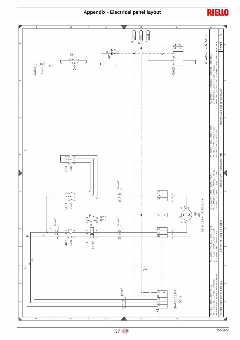
Appendix - Electrical panel layout
!"##$%%&
'()
*+,--./ -0
1-23
'45)
'6)
'70
+
'48)
'4!)
'(9:(
'!)
'(9:(
;!,--.<%'%;!1--.<
'2)
)/
,
1=
>?
)/
,
1=
>?
9
@
A
B
< 6
9
@
A
B
< 6
!A2<79%:*C6C59;<%BC%DE8<*F9
59GE:8%E6%:*C6C59;%E:8D:8
<C*B;928CH<!%5<C!8:*H!!A2<79
!A2<79%:*C6C59C;<%B<%D:C!!9*A<
5)
5)
5/
5/
5
5
I,JJK
*
D<
5)
5/
,JJK
5
5)
.,LB,
)
1
/,
=
/
)
,
1
=
=L M)-9
.,L@=
.,L@/
N>
N?
N1
N=
)--
:)
O)
0)
:)
0/
O/
:/
D<
P@@
;!,--%>L1%QO%'%;!1--%NR/%QO
5/ )-)
0)
5 )-/
O)
I,JJK
I,JJK
D<
.,LB/
)
1
/,
=
)-
0/
)-,
O/
)-1
:/
I,JJK
.,LB
)
1
/,
=
5)
6
=L 9%8
5)9
) /
) /
)
)
)
*
H*
() (/
*
D<
D<
*
.,L<)
D<
.1L<)
)
.,L9)
7
@:%S%@5:%.%@5:<%.%@5<:%.%@59:
@4%S%*<;E%.%@59A4%.%*EC;%.%!A2O9;F
G<%S%HC955E%.%G<55EO%.%T9:*<%.%H<5@
H*%S%0<;B<%.%H;<<*%.%0<;8%.%H;U*
;B%S%;E!!E%.%;<B%.%;E:H<%.%;E8
O2%S%@C9*AE%.%O2C8<%.%@59*A%.%O<C!!
EHS%9;9*ACE%.%E;9*H<%.%E;9*H<%.%E;9*H<
08S%0CE5<88E%.%0CE5<8%.%0CE5<8%.%0CE5<88
HGS%H;CHCE%.%H;<G%.%H;C!%.%H;9:
D4S%;E!9%.%DC*4%.%;E!<%.%;E!9
HBS%E;E%.%HE5B%.%E;%.%HE5B
8VS%8:;A2<!<%.%8:;V:EC!<%.%8:;V:EC!<%.%8:;4C!@59:
!;S%9;H<*8E%.%!C50<;%.%9;H<*8%.%!C5@<;
H*G<S%HC955E.0<;B<%.%G<55EO.H;<<*%.%T9:*<.0<;8%.%H<[email protected];:*
@*%S%79;;E*<%.%@;EO*%.%79;;E*%.%@;9:*
:)
0)O)
0/O/
:/
37 20041904GB

Appendix - Electrical panel layout
!"##$%%&
'()
*+,--./ -0
1-23
'45)
'6)
'70
+
'48)
'4!)
'(9:(
'!)
'(9:(
'2)
;!<1-.=%'%;!>--.=
)/
,
1<
?>
)/
,
1<
?>
9
@
A
B
= 6
9
@
A
B
= 6
!A2=79%:*C6C59;=%BC%DE8=*F9
59GE:8%E6%:*C6C59;%E:8D:8
=C*B;928CH=!%5=C!8:*H!!A2=79
!A2=79%:*C6C59C;=%B=%D:C!!9*A=
5)
5)
5/
5/
5
5
I)-JJK
*
*
D=
D=
,JJK
)-JJK
.,LB,
)
1
/,
<
/
)
,
1
<
/-M/19
.,L@<
.,L@/
N?
N>
N1
N<
:)
O)
0)
:)
0/
O/
:/
D=
P@@
/)QO
0)
O)
D=
.,LB/
)
1
/,
<
0/
O/
:/
?I<JJK
.,LB
)
1
/,
<
5)
6
<L 9%8
5)9
) /
) /
)
)
)
)
*
H*
() (/
*
D=
*
.,L=)
D=
.1L=)
)
.,L9)
7
@:%R%@5:%.%@5:=%.%@5=:%.%@59:
@4%R%*=;E%.%@59A4%.%*EC;%.%!A2O9;F
G=%R%HC955E%.%G=55EO%.%S9:*=%.%H=5@
H*%R%0=;B=%.%H;==*%.%0=;8%.%H;T*
;B%R%;E!!E%.%;=B%.%;E:H=%.%;E8
O2%R%@C9*AE%.%O2C8=%.%@59*A%.%O=C!!
EHR%9;9*ACE%.%E;9*H=%.%E;9*H=%.%E;9*H=
08R%0CE5=88E%.%0CE5=8%.%0CE5=8%.%0CE5=88
HGR%H;CHCE%.%H;=G%.%H;C!%.%H;9:
D4R%;E!9%.%DC*4%.%;E!=%.%;E!9
HBR%E;E%.%HE5B%.%E;%.%HE5B
8UR%8:;A2=!=%.%8:;U:EC!=%.%8:;U:EC!=%.%8:;4C!@59:
!;R%9;H=*8E%.%!C50=;%.%9;H=*8%.%!C5@=;
H*G=R%HC955E.0=;B=%.%G=55EO.H;==*%.%S9:*=.0=;8%.%[email protected];:*
@*%R%79;;E*=%.%@;EO*%.%79;;E*%.%@;9:*
20041904 38 GB

Appendix - Electrical panel layout
!"##$%%&
'()
'*+)
'*+)
'*)
'*)
'()
',-
'*-
'*-
.!/0012%
)-
/
34
56
)-
/
34
56
7
8
9
:
2 (
7
8
9
:
2 (
!9,2;7%(<=>?@=7+2
@A2.7B?@=7+%+7C@<B
82B.?28!!9,2;7
!9,2;7%(@=9B?@==2+
)
1/D:6
=
1/D:6
1/D9/
E3
E4
7-
7)
1/D8/
1/D8/
1/D8/
15D8-
)
/ 3
)/
-
4
)
-
7)
7-
16D93
)
)-
))
1/D9/
E5
E6
.:
F) F-
)
6
7)
7-
16D94
)
)-
))
)
13D2)
)6
15D8)
=
13D2)
8<%G%8+<%1%8+<2%1%8+2<%1%8+7<
8*%G%=2.@%1%8+79*%1%=@?.%1%!9,H7.>
C2%G%I?7++@%1%C2++@H%1%J7<=2%1%I2+8
I=%G%K2.:2%1%I.22=%1%K2.B%1%I.L=
.:%G%.@!!@%1%.2:%1%.@<I2%1%.@B
H,%G%8?7=9@%1%H,?B2%1%8+7=9%1%H2?!!
@IG%7.7=9?@%1%@.7=I2%1%@.7=I2%1%@.7=I2
KBG%K?@+2BB@%1%K?@+2B%1%K?@+2B%1%K?@+2BB
ICG%I.?I?@%1%I.2C%1%I.?!%1%I.7<
A*G%.@!7%1%A?=*%1%.@!2%1%.@!7
I:G%@.@%1%I@+:%1%@.%1%I@+:
BMG%B<.9,2!2%1%B<.M<@?!2%1%B<.M<@?!2%1%B<.*?!8+7<
!.G%7.I2=B@%1%!?+K2.%1%7.I2=B%1%!?+82.
I=C2G%I?7++@1K2.:2%1%[email protected]=%1%J7<=21K2.B%1%I2+81I.<=
8=%G%;7..@=2%1%8.@H=%1%;7..@=%1%8.7<=
39 20041904GB

Appendix - Electrical panel layout
!"##$%%&
'()
'*!+)
'*!+)
'*!+)
'*!)
'*+)
'*+)
'*!+)
'*+)
'*!)
'*!)
'*!)
'*,)
'*,)
'*,)
'*)
'*)
'()
'-.
'*.
'*.
/! 0012%'%/!30012%'%/!43012%'%/!50012
).
6
34
75
).
6
34
75
8
9
:
;
2 (
8
9
:
;
2 (
!:-2<8%(=>?@A>8,2%8BB@8+A/2%!+2,,81+/@8>CA,A
!+8/1;2,+8%!+8/+2/%AD2/8+@A>8,%,8EA=+
92+/@29!!:-2<8%%;2!%!+2/>';/2@2:*8>,8!!2/!
!:-2<8%(A>:+@A>>2,%;2<8//2=/%2+A@,21+/@8>C,2
)
16F;5
>
16F;5
16F:6
G3
G4
.
8)
8.
96
)5
)4
)3
9.
.5
.4
.3
;.
.3
.4
.5
6
;6
.)
..
8)
8.
16F9
16F9
16F9
:6
)
6 3
))
.
4
).
;.
)3
)4
)5
3
;.
))
).
4
8)
8.
16F93
16F93
16F93
9
)
6 3
)6
.
4
)
:.
.)
..
.
;6
)6
)
7
8)
8.
16F96
16F96
16F96
93
)
6 3
)6
.
4
)
17F9.
.6
.
;
)6
)
8)
8.
15F:3
)
).
))
) )5
16F:6
G7
G5
/;
H) H.
5
8)
8.
15F:4
)
).
))
)
13F2)
)5
17F9)
>
13F2)
9=%I%9,=%1%9,=2%1%9,2=%1%9,8=
9*%I%>2/A%1%9,8:*%1%>A@/%1%!:-J8/?
E2%I%C@8,,A%1%E2,,AJ%1%K8=>2%1%C2,9
C>%I%B2/;2%1%C/22>%1%B2/+%1%C/L>
/;%I%/A!!A%1%/2;%1%/A=C2%1%/A+
J-%I%9@8>:A%1%J-@+2%1%9,8>:%1%J2@!!
ACI%8/8>:@A%1%A/8>C2%1%A/8>C2%1%A/8>C2
B+I%B@A,2++A%1%B@A,2+%1%B@A,2+%1%B@A,2++
CEI%C/@C@A%1%C/2E%1%C/@!%1%C/8=
D*I%/A!8%1%D@>*%1%/A!2%1%/A!8
C;I%A/A%1%CA,;%1%A/%1%CA,;
+MI%+=/:-2!2%1%+=/M=A@!2%1%+=/M=A@!2%1%+=/*@!9,8=
!/I%8/C2>+A%1%!@,B2/%1%8/C2>+%1%!@,92/
C>E2I%C@8,,A1B2/;2%1%E2,,AJ1C/22>%1%K8=>21B2/+%1%C2,91C/=>
9>%I%<8//A>2%1%9/AJ>%1%<8//A>%1%9/8=>
20041904 40 GB

Appendix - Electrical panel layout
!"##$%%&
'()*+
',*)*,
' -
).
)/,
,-
(+
0
12
,-
(+
0
12
.
3
4
5
6 7
.
3
4
5
6 7
!4869.%7:;<=>;.?6%?9@ ,AAA
?9@ ,AAA%>B6C./=>;.?%?.D>:/
36/C=63!!4869.%?9@ ,AAA
!4869.%7>;4/=>;;6?%?9@ ,AAA
,
E+A.2
;
E+A62
B6
E(A52
?9@ ,AAAA
,?
B6
;?
!.76/D%?>>B
?F>
F
,
76
/C.7>
=;%,-@%.4
;
,
E0A3,
,
>:/%-(*@%.4
B>G6C%-(*@%.4
,
,,
E0A4,
,*
E0A4,
',*),+
',*),(
--*@
BC=
!6H%=
!6H%-
, -
, - , - ( +
',*),-
',*),,
' -),
' -)-
' -)(
,
E1A5,
;
E1A5,
B6
E1A5,
3:%I%3?:%E%3?:6%E%3?6:%E%3?.:
3H%I%;6C>%E%3?.4H%E%;>=C%E%!48G.C<
D6%I%F=.??>%E%D6??>G%E%J.:;6%E%F6?3
F;%I%@6C56%E%FC66;%E%@6C/%E%FCK;
C5%I%C>!!>%E%C65%E%C>:F6%E%C>/
G8%I%3=.;4>%E%G8=/6%E%3?.;4%E%G6=!!
>FI%.C.;4=>%E%>C.;F6%E%>C.;F6%E%>C.;F6
@/I%@=>?6//>%E%@=>?6/%E%@=>?6/%E%@=>?6//
FDI%FC=F=>%E%FC6D%E%FC=!%E%FC.:
BHI%C>!.%E%B=;H%E%C>!6%E%C>!.
F5I%>C>%E%F>?5%E%>C%E%F>?5
/LI%/:C486!6%E%/:CL:>=!6%E%/:CL:>=!6%E%/:CH=!3?.:
!CI%.CF6;/>%E%!=?@6C%E%.CF6;/%E%!=?36C
F;D6I%F=.??>E@6C56%E%D6??>GEFC66;%E%J.:;6E@6C/%E%F6?3EFC:;
3;%I%9.CC>;6%E%3C>G;%E%9.CC>;%E%3C.:;
,-@%.4,
,-@%.4
.FF A--*
,-@%.4-
41 20041904GB

Appendix - Electrical panel layout
!"##$%%&
'()
'*!
+
(,'-,
(.'-,
(/'-)
'0/
(,'-,
(,'-1
(/'-1
( '-)
'*2
+
'+0
'+3456
'+37+
'(+34
'+34
'(+34)
)1
,8
/
9:
)1
,8
/
9:
0
;
<
=
> ?
0
;
<
=
> ?
!<@>40%?ABCDEB02>%247/)FFF
247/)FFF%E+>G0*DEB02%20HEA*
;>*GD>;!!<@>40%247/)FFF
!<@>40%?EB<*DEBB>2%247/)FFF
))
I/F;8
)-
I/F<8
)-
*!)
J;<
247/)FFFF
?20B3>
KLM
<+D
2
)
2K56
+>
)
+%ED2
+%30!%'%<+D
K56
)
I/F;1
?20B3>
)))
+
2KLM
+>
)
@E%!*0G*
2!*0G*
)
2
ED2
(,',) ))
*!1
),
*2)
J;<
)1
*21
+
+1
,
)1
+N
(.',8 (.',8
+1
)1 ,
J;<
+
+
+N
(.',,
(.',1
(.',) (.',)
+)
+7+
)1 ,
J;<
+7+
+7+
+
(.',1
+7+
(.',,
, )1 ,
J;;
J;;
)1
,
+)
+
+O
)8
<E=F
),
I))F<)
)1
I9F<)
;A%P%;2A%I%;2A>%I%;2>A%I%;20A
;Q%P%B>GE%I%;20<Q%I%BEDG%I%!<@R0GC
H>%P%3D022E%I%H>22ER%I%S0AB>%I%3>2;
3B%P%7>G=>%I%3G>>B%I%7>G*%I%3GTB
G=%P%GE!!E%I%G>=%I%GEA3>%I%GE*
R@%P%;D0B<E%I%R@D*>%I%;20B<%I%R>D!!
E3P%0G0B<DE%I%EG0B3>%I%EG0B3>%I%EG0B3>
7*P%7DE2>**E%I%7DE2>*%I%7DE2>*%I%7DE2>**
3HP%3GD3DE%I%3G>H%I%3GD!%I%3G0A
+QP%GE!0%I%+DBQ%I%GE!>%I%GE!0
3=P%EGE%I%3E2=%I%EG%I%3E2=
*UP%*AG<@>!>%I%*AGUAED!>%I%*AGUAED!>%I%*AGQD!;20A
!GP%0G3>B*E%I%!D27>G%I%0G3>B*%I%!D2;>G
3BH>P%3D022EI7>G=>%I%H>22ERI3G>>B%I%S0AB>I7>G*%I%3>2;I3GAB
;B%P%40GGEB>%I%;GERB%I%40GGEB%I%;G0AB
20041904 42 GB

Appendix - Electrical panel layout
!"##$%%&
'()
'*!
(+',)
'-.
(/',)
(.',/
(0',)
'!1/
'23)
'!4
'
'!+
5
'6*
7
'2/
'2/
'!1/
)4
/+
.8
0
)4
/+
.8
0
-
9
:
;
< =
-
9
:
;
< =
!:1<>-%=?@ABC@-3<%3>D.)EEE
3>D.)EEE%C7<*-6BC@-3%3-FC?6
9<6*B<9!!:1<>-%3>D.)EEE
!:1<>-%=C@:6BC@@<3%3>D.)EEE
)0
G+E-0
)4
G8E;0
)
G.E<0
@
G.E<0
7<
G.E<0
(+')+
*!)
59:
)
*!4
@
7<
3>D.)EEEE
CB3
H-!
)
*<!<6
G.E94
)
/C@GC==
)
3
)
H-!%5%CB3
4>C6C*
-3-*>
H-!
CB3
(+')+
/ +
:8
()
(4
)
(+')/
G+E;+
4/
4+
)4
)
,
)
4
)
4
/
+
/
+
/
+
'
5
>-@
>-@
(.'/)
).
).
68
59:
)
)
60
)8
)8
6
)+
7<
-)
-4
G0E:
)+
)4
))
(/')4
*;
() (4
:4
)+
G))E:)
)
G))E-)
@
G0E9)
7<
G0E:)
).
G))E:)
)
G))E:)
)8
G))E9)
9?%I%93?%G%93?<%G%93<?%G%93-?
92%I%@<*C%G%93-:2%G%@CB*%G%!:1J-*A
F<%I%HB-33C%G%F<33CJ%G%K-?@<%G%H<39
H@%I%D<*;<%G%H*<<@%G%D<*6%G%H*L@
*;%I%*C!!C%G%*<;%G%*C?H<%G%*C6
J1%I%9B-@:C%G%J1B6<%G%93-@:%G%J<B!!
CHI%-*-@:BC%G%C*-@H<%G%C*-@H<%G%C*-@H<
D6I%DBC3<66C%G%DBC3<6%G%DBC3<6%G%DBC3<66
HFI%H*BHBC%G%H*<F%G%H*B!%G%H*-?
72I%*C!-%G%7B@2%G%*C!<%G%*C!-
H;I%C*C%G%HC3;%G%C*%G%HC3;
6MI%6?*:1<!<%G%6?*M?CB!<%G%6?*M?CB!<%G%6?*2B!93-?
!*I%-*H<@6C%G%!B3D<*%G%-*H<@6%G%!B39<*
H@F<I%HB-33CGD<*;<%G%F<33CJGH*<<@%G%K-?@<GD<*6%G%H<39GH*?@
9@%I%>-**C@<%G%9*CJ@%G%>-**C@%G%9*-?@
,
-?6C
>-@
43 20041904GB

Appendix - Electrical panel layout
!"##$%%&
'()
'*
(+',)
'-.
(+',/
(0',1
'23
'23
'2)
'2/
'21
'23
)/
10
.3
4
)/
10
.3
4
-
5
6
7
8 9
-
5
6
7
8 9
!6:8;-%9<=>?@=-A8%A;B.)CCC
A;B.)CCC%@D8E-F?@=-A%A-*@<F
58FE?85!!6:8;-%A;B.)CCC
!6:8;-%9@=6F?@==8A%A;B.)CCC
=
G4C7
D8
G4C7
=
=D)
D/
D8
=
B)
B/
5<
5=
52
H/I
H1I
A;B.)CCCC
B)
B/
)
G.C5/
)
=D8
A=
D8
)
!B
DB
(+')0
B)
(+')1
B/
D8
-/
-)
6
)0
)/
))
D8
G0C7.
))
)/
)0
9-=%@=
+.
)
+.-
/
G0C74
))
)/)0
@B8EA@-7
+3
1
+3-
0
G4C63
))
)/
)0
5<E=8E
A@62'@<F
+4
.
+4-
3
61
))
)/)0
5<E=8E%@=
+
4
+ -
=
G))C-)
D8
G))C-)
5<%J%5A<%G%5A<8%G%5A8<%G%5A-<
52%J%=8E@%G%5A-62%G%=@?E%G%!6:K-E>
*8%J%L?-AA@%G%*8AA@K%G%M-<=8%G%L8A5
L=%J%B8E78%G%LE88=%G%B8EF%G%LEN=
E7%J%E@!!@%G%E87%G%E@<L8%G%E@F
K:%J%5?-=6@%G%K:?F8%G%5A-=6%G%K8?!!
@LJ%-E-=6?@%G%@E-=L8%G%@E-=L8%G%@E-=L8
BFJ%B?@A8FF@%G%B?@A8F%G%B?@A8F%G%B?@A8FF
L*J%LE?L?@%G%LE8*%G%LE?!%G%LE-<
D2J%E@!-%G%D?=2%G%E@!8%G%E@!-
L7J%@E@%G%L@A7%G%@E%G%L@A7
FOJ%F<E6:8!8%G%F<EO<@?!8%G%F<EO<@?!8%G%F<E2?!5A-<
!EJ%-EL8=F@%G%!?AB8E%G%-EL8=F%G%!?A58E
L=*8J%L?-AA@GB8E78%G%*8AA@KGLE88=%G%M-<=8GB8EF%G%L8A5GLE<=
5=%J%;-EE@=8%G%5E@K=%G%;-EE@=%G%5E-<=
20041904 44 GB

Appendix - Electrical panel layout
!"##$%%&
'()*)+
*,-
'.*)+
'/*)0
'()*)0
*'!
*123
*451
*6,
(+
0.
-7
/8
(+
0.
-7
/8
,
9
:
;
< =
,
9
:
;
< =
!:><?,%=@3A123,B<%B?C-(DDD
B?C-(DDD%2E<5,6123,B%B,F2@6
9<651<9!!:><?,%B?C-(DDD
!:><?,%=23:61233<B%B?C-(DDD
B?C-(DDDD
3B
(
=!CG451
G-D9+
E<
B3
459
45:
E2H<5
451
E<
123
(
B
(
=B,?<
(
1I316123
!6,56
E<
'()*0(
(
9J
9@
93
K99
K99
'()*+7
-.
'()*++
+/
:2;D
'.*+0
+0)C
8LC
E<
'/*+-
9@%M%9B@%G%9B@<%G%9B<@%G%9B,@
9J%M%3<52%G%9B,:J%G%3215%G%!:>H,5A
F<%M%I1,BB2%G%F<BB2H%G%N,@3<%G%I<B9
I3%M%C<5;<%G%I5<<3%G%C<56%G%I5O3
5;%M%52!!2%G%5<;%G%52@I<%G%526
H>%M%91,3:2%G%H>16<%G%9B,3:%G%H<1!!
2IM%,5,3:12%G%25,3I<%G%25,3I<%G%25,3I<
C6M%C12B<662%G%C12B<6%G%C12B<6%G%C12B<66
IFM%I51I12%G%I5<F%G%I51!%G%I5,@
EJM%52!,%G%E13J%G%52!<%G%52!,
I;M%252%G%I2B;%G%25%G%I2B;
64M%6@5:><!<%G%6@54@21!<%G%6@54@21!<%G%6@5J1!9B,@
!5M%,5I<362%G%!1BC<5%G%,5I<36%G%!1B9<5
I3F<M%I1,BB2GC<5;<%G%F<BB2HGI5<<3%G%N,@3<GC<56%G%I<B9GI5@3
93%M%?,5523<%G%952H3%G%?,5523%G%95,@3
9B,:J
9B@<
952H3
451DDD
45 20041904GB

Appendix - Electrical panel layout
!
"#$$%&&'
()*+,
)-!
(*-
)-
(.
-!
(*+,
*+,-/0
(.
-
()"1
("1
("12
)
)2
)
)2
2
34
-5
67
2
34
-5
67
*
8
9
:
; <
*
8
9
:
; <
"9=;1*&<>?+@A?*,;&,1B- ///
,1B- ///&AC;D*E@A?*,&,*FA>E
8;ED@;8""9=;1*&,1B- ///
"9=;1*&<A?9E@A??;,&,1B- ///
,1B- ////
G?:
9*?&,
H-/82
2B*92
9*?&=
2*9
"#I$JK
G?:
9*?&,
2B*92
9*?&=
2B*9
"#I$JK
8>"
8L
*GG-/53!H53
3
M18
2B*9
2B*92
9*?,
9*?=
G?:
"=@;,:
32
64
7
G?
2
F;
6
8?
4
.=
7
N#
8L
*GG-/54!H54
8L
G?
F;
8?
.=
N#
8L
G?
F;
8?
.=
N#
M88
M88
G?:
9*?&,
2B*92
9*?&=
2*9
"#I$JK
"#I$JK
G?:
9*?&,
2B*92
9*?&=
2*9
G?:
9*?&,
2B*92
9*?&=
2*9
"#I$JK
G?:
9*?&,
2B*92
9*?&=
2*9
"#I$JK
G?
2
F;
3
8?
4
.=
-
N#
75
9A:/
8>&O&8,>&H&8,>;&H&8,;>&H&8,*>
8L&O&?;DA&H&8,*9L&H&?A@D&H&"9=.
*D+
F;&O&G@*,,A&H&F;,,A.
&H&P*>?;&H&G;,8
G?&O&B;D:;&H&GD;;?&H&B;DE&H&GDQ?
D:&O&DA""A&H&D;:&H&DA>G;&H&DAE
.=&O&8@*?9A&H&.
=@E;&H&8,*?9&H&.
;@""
AGO&*D*?9@A&H&AD*?G;&H&AD*?G;&H&AD*?G;
BEO&B@A,;EEA&H&B@A,;E&H&B@A,;E&H&B@A,;EE
GFO&GD@G@A&H&GD;F&H&GD@"&H&GD*>
CLO&DA"*&H&C@?L&H&DA";&H&DA"*
G:O&ADA&H&GA,:&H&AD&H&GA,:
ERO&E>D9=;";&H&E>DR>A@";&H&E>DR>A@";&H&E>DL@"8,*>
"DO&*DG;?EA&H&"@,B;D&H&*DG;?E&H&"@,8;D
G?F;O&G@*,,AHB;D:;&H&F;,,A.
HGD;;?&H&P*>?;HB;DE&H&G;,8HGD>?
8?&O&1*DDA?;&H&8DA.
?&H&1*DDA?&H&8D*>?
20041904 46 GB
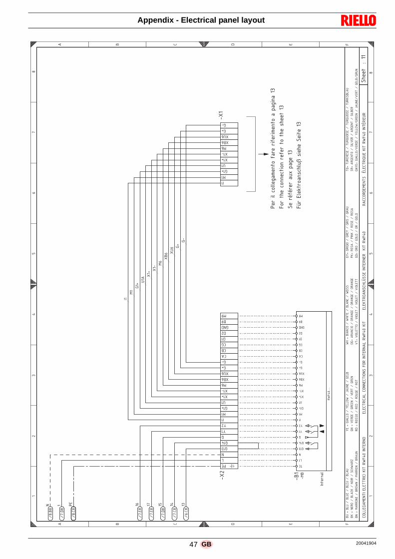
Appendix - Electrical panel layout
!"##$%%&
'()
'*
+#,%-.%/0..#123#4$0%52,#%,-5#,-3#4$0%2%621-42% 7
80,%$"#%/044#/$-04%,#5#,%$0%$"#%9"##$% 7
!#%,:5:,#,%2;<%621#% 7
8=,%>.#?$,0249/".;@%9-#"#%!#-$#% 7
'(
)
7A
BC
DE
)
7A
BC
DE
F
*
G
H
> 8
F
*
G
H
> 8
GIJJ>KFL>MNO%>J>NNPOGO%QON%PR
8AS%OMN>PMI
>J>GNPOGFJ%GIMM>GNOIM!%8IP%OMN>PMFJ%PR
8AS%QON
>J>QNPIFM!GTJU!!>%OMN>PM>P%%QON%PR
8AS
PFGGIPH>L>MN!%%VJ>GNPOWX>%QON%PR
8AS%OMNVPO>XP
M
YEZ*E
YDZHE
+>
YEZGE
C
YDZ>E
D
YDZ>E
B
YDZHE
A
YDZGE
7
YCZGE
+>
'L*
O4$#,42.
J
M
W 7
W A
W
[
[)
O
L
K \
X
( \
( '
LC
(*C
(XC
K\
K'
GF
G*
GK
H
H)
KMH
*]
L]
O
L
K \
X F
( \
( '
LC
(*C
(XC
K\
K'
O
L
K \
X
( \
( '
LC
(*C
(XC
K\
K'
*X%^%*JX%Y%*JX>%Y%*J>X%Y%*JFX
*Q%^%M>PI%Y%*JFGQ%Y%MIOP%Y%!GTR
FP_
[>%^%KOFJJI%Y%[>JJIR
%Y%`FXM>%Y%K>J*
KM%^%a>PH>%Y%KP>>M%Y%a>PN%Y%KPUM
PH%^%PI!!I%Y%P>H%Y%PIXK>%Y%PIN
RT%^%*OFMGI%Y%R
TON>%Y%*JFMG%Y%R
>O!!
IK^%FPFMGOI%Y%IPFMK>%Y%IPFMK>%Y%IPFMK>
aN^%aOIJ>NNI%Y%aOIJ>N%Y%aOIJ>N%Y%aOIJ>NN
K[^%KPOKOI%Y%KP>[%Y%KPO!%Y%KPFX
+Q^%PI!F%Y%+OMQ%Y%PI!>%Y%PI!F
KH^%IPI%Y%KIJH%Y%IP%Y%KIJH
NW^%NXPGT>!>%Y%NXPWXIO!>%Y%NXPWXIO!>%Y%NXPQO!*JFX
!P^%FPK>MNI%Y%!OJa>P%Y%FPK>MN%Y%!OJ*>P
KM[>^%KOFJJIYa>PH>%Y%[>JJIR
YKP>>M%Y%`FXM>Ya>PN%Y%K>J*YKPXM
*M%^%LFPPIM>%Y%*PIR
M%Y%LFPPIM%Y%*PFXM
PR
8ASZZZZ
N>
J
M
W 7
W A
W
[
[)
O
L
K \
X
( \
( '
LC
(*C
(XC
K\
K'
GF
G*
GK
H
H)
KMH
*]
L]
47 20041904GB

Appendix - Electrical panel layout
!
"#$$%&&'
!&(
!)&(
*"&+,,-.
/
!,&(
+!&(
*"&0,,-.
/
!)&(
),&(
*"&),,-.
/
0,&(
1,&(
*"&2),-.
/
),&(
,,&(
*"&1,,-.
/
34
34
35
.6.78*97(6&:;<
.*
=("&>(6>.?:>:&6.(@&A.8.789;B
3:=CDE
3:=>:
38*
:
:;<
.*&*.=F6(89;B&<
98G
+3:;"989;B&7;B8(78
38*
:
34
3*"
9BA97(8;*"-(B7966(*9."
34
38"
:
HIJ& ,(&(7 &!+,>&(7
HIJ&!(&(7 )&!+,>&(7
8*9==.*9B=-"(K.85&A.>97."
386
:
!
+0
)2
L1
!
+0
)2
L1
(
M
7
A
. K
(
M
7
A
. K
7;66.=(C.B89&.6.88*979&(&7F*(&A.66N&9B"8(66(8;*.
.6.78*97(6&7;BB.789;B"&".8&M5&9B"8(66.*
.6.@8*;(B"7G6O"".&>;C&9B"8(66(8.F*&(F"PFKOG*.B
*(77;*A.C.B8"&Q6.78*9RF.&.KK.78FQ&:(*&6N&9B"8(66(8.F*
+B&&&&0,,&>&),&GS
6
6!
6+
:.
"&THHUV
K&T(V
"&7(M6.
0&HHU&THDEV
KF".
W=
IC
+&&&0,,&>&),&GS
B
6
6!
6+
B
K&T(V
0X)&Y<
+
K(B&C;8;*&(BA
8G.*C(6&*.6(5
Z&(
K&T(V
"&7(M6.
2&HHU&THDEV
KF".
W=
IC
LX)&Y<
+
K(B&C;8;*&(BA
8G.*C(6&*.6(5
K&T(V
"&7(M6.
2&HHU&THDEV
KF".
W=
IC
+
K(B&C;8;*&(BA
8G.*C(6&*.6(5
K&T(V
"&7(M6.
,&HHU&THDEV
KF".
W=
IC
+
K(B&C;8;*&(BA
8G.*C(6&*.6(5
K&T(V
"&7(M6.
,&HHU&THDEV
KF".
W=
IC
+
K(B&C;8;*&(BA
8G.*C(6&*.6(5
ZX!&Y<
1X)&Y<
!!&Y<
+&&&0,,&>&),&GS
+&&&0,,&>&),&GS
+&&&0,,&>&),&GS
+&&&0,,&>&),&GS
:.
ZX1&(
!,XL&(
!0X+&(
1X &(
B
B:
:!
:.
B
>
>!
MF
MB
M@
T!V
T+V
B.6&7(";&A9&9B8.**F88;*.&C(=B.8;8.*C97;
"7.=69.*.&96&89:;&7
<98G&(&C(=B.8;38G.*C(6&"<
987G
7G;;".&85:.&7
>
>!
:.
:
:&
.B&7("&AN&9B8.**F:8.F*&C(=BQ8;8G.*C9RF.
7G;9"9*&6.&85:.&7
9C&K(66.&.9B."&C(=B.8;8G.*C9"7G.B
"7G(68.*"&85:&7&<
[G6.B
+
!
:\
:!
:&
:>:
:>:&
:>:
:>:&
+
!
:\
82
9]&"%IW$
8L
81
99]&"%IW$
*"
*.".8
*"!
=.M6[".&.9B
F"798(&7;B8(889&:F6989
>;68(=.&K*..&7;B8(78&;F86.8
>.B896(8.F*&(66FCQ
K(B&;B
>.B896(8;*.&(77.";
!
"8^*(M"7G(68FB=&A."&C;8;*"
M6;7(=.&C;8.F*
C;8;*&6;7@&;F8
+ M6;77;&C;8;*.
0
8"
8"!
?M7
";*89.&7;B8(78"&:*;:*."
(F"=(B=&KO*&*.9B@;B8(@8.
"8^*(M"7G(68FB=&A."&M*.BB.*"
M6;7(=.&M*F6.F*
MF*B.*&6;7@&;F8
) M6;77;&M*F79(8;*.
2
86
86!
?M7
K6(CC.&.9B
K6(CC.&(66FCQ.
K6(C.&(69=G8
L K9(CC(&(77."(
1
&/
&/
&/
&/
&/
&/
MF&_&M6F&-&M6F.&-&M6.F&-&M6(F
M@&_&B.*;&-&M6(7@&-&B;9*&-&"7G<
(*P
5.&_&=9(66;&-&5.66;<
&-&`(FB.&-&=.6M
=B&_&>.*A.&-&=*..B&-&>.*8&-&=*OB
*A&_&*;"";&-&*.A&-&*;F=.&-&*;8
<G&_&M9(B7;&-&<
G98.&-&M6(B7&-&<
.9""
;=_&(*(B79;&-&;*(B=.&-&;*(B=.&-&;*(B=.
>8_&>9;6.88;&-&>9;6.8&-&>9;6.8&-&>9;6.88
=5_&=*9=9;&-&=*.5&-&=*9"&-&=*(F
:@_&*;"(&-&:9B@&-&*;".&-&*;"(
=A_&;*;&-&=;6A&-&;*&-&=;6A
8R_&8F*7G.".&-&8F*RF;9".&-&8F*RF;9".&-&8F*@9"M6(F
"*_&(*=.B8;&-&"96>.*&-&(*=.B8&-&"96M.*
=B5._&=9(66;->.*A.&-&5.66;<
-=*..B&-&`(FB.->.*8&-&=.6M-=*FB
MB&_&C(**;B.&-&M*;<
B&-&C(**;B&-&M*(FB
A9*.78&"8(*8
".8&8;
<!
F!
>!
F
>
<
A.68(&-&"8(*
".8&8;
".8&8;
".8&8;
".8&8;
<!
F!
>!
F
>
<
A.68(&-&"8(*
<!
F!
>!
F
>
<
A.68(&-&"8(*
<!
F!
>!
F
>
<
A.68(&-&"8(*
<!
F!
>!
F
>
<
2X+
,
!,
!)
!,
!)
2X+
,
Z )
20041904 48 GB

Appendix - Electrical panel layout
!
"#$$%&&'
()*
(+
(),-
.
/012/345
(),-
.
6
()
"7,8297
(
()
(+1
(),-
.
(+17)1
952:4129&9/:073"412/3
()
(+0
:/;<5412/3&230<1&-
21=&>+7?*@(0AAAAA
(+1*
(),-
.
(+,
(+1!
()
(+0
(+1B
(+4
6(
0/""2+2521C&/.&0,/+7&230<1
!"
#
$%&&'!'(')*+%,++-%./(")'%0+'0$/)+1')2+3'4((%+$3%!4&
56
!76
#
!7
#
$%&&'!'(')*+%,+&4)$%'0)+'0$/)+"0.+&4)$%'0)+&2',)
68
9:
;<
=>
68
9:
;<
=>
"
!
?
.
4 ,
"
!
?
.
4 ,
&?24-"+,/0@'%0"(4+31,:ABBB
31,:ABBB+%$43")'%0"(+("*%/)
!4)3'4!&&?24-"+31,:ABBB
&?24-"+,%0?)'%004(+31,:ABBB
'C+DEFG+HI+EJJKIDELIGCM+HMK+NIO+31,:A
ICOMPCG+OGQKIMPM+IK+JGCOM+E+RIKG+S69 S6:
HEKKE+TGPFMOOIMPE+58
'T+,EKKM+MICMP+"CUMCHVCQ+HMF+ICOMPCMC+NIOF
31,:A+HIM+.PEWOXYMPYPXDZVCQ+S69 S6:
[GT+NKMTTMCYPMOO+58+MCORMPCMC
1WMC+EJJK\ICQ+OWM+ICOMPCEK+31,:A+ZIO]
PMTG[M+UIPM+^VTJMP+S69 S6:
RPGT+OMPTICEK+YGEPH+58
4C+DEF+H_+EJJKIDEOIGC+HV+ZIO+31,:A+ICO`PIMVP
MCKM[MP+KM+JGCO+HM+TMFVPM
a+RIK+S69 S6:+HV+YGPCIMP+58
$4
#-!
(
56#
0
-GHVKEOICQ+GVOJVO
Ab:c+ +8AT"++Ab8c+ 6A7+.?
S69
S6: 56
S
*6
*8
'6
-6 ?"
3d.)d.+#
e6#
/6
56#
?!
3d.)d.+
&MPIEK+'COMPREDM+3&:>;
56
-<
5!<
5/< ?e
e0.
e#
e
?"
?!
?e
.6
e#
.8
e0.
!f
%JMPEOICQ+[GKOEQM+RGP+OPECFHVDMP
.?+8:7+g+9AT"
-f
e
'6
-f
-6
!f
-6
e
12
!0
S!4<8A $BBBBB
e0
Ag6A7
e#
e6#
/6
-6
-<
'6
5!<
e6#
-6
e6#
$4
68
$4
:BBBB8AT"
$O+6AA
12
12
3.
3.
#!?
#!?
5!<
A 8AT"++: 8AT"+.?
'6
A 8AT"++: 8AT"+.?
'6
-<
-6
-6
-6
e
5/<
A 67++A 6A7+.?
/6
A 67++A 6A7+.?
e#
'6
-<
-6
#
#
#
##
!/+h+!(/+g+!(/4+g+!(4/+g+!("/
!N+h+043%+g+!("?N+g+0%'3+g+&?21"3@
*4+h+e'"((%+g+*4((%1+g+i"/04+g+e4(!
e0+h+743.4+g+e3440+g+743)+g+e3j0
3.+h+3%&&%+g+34.+g+3%/e4+g+3%)
12+h+!'"0?%+g+12')4+g+!("0?+g+14'&&
%eh+"3"0?'%+g+%3"0e4+g+%3"0e4+g+%3"0e4
7)h+7'%(4))%+g+7'%(4)+g+7'%(4)+g+7'%(4))
e*h+e3'e'%+g+e34*+g+e3'&+g+e3"/
$Nh+3%&"+g+$'0N+g+3%&4+g+3%&"
e.h+%3%+g+e%(.+g+%3+g+e%(.
)Sh+)/3?24&4+g+)/3S/%'&4+g+)/3S/%'&4+g+)/3N'&!("/
&3h+"3e40)%+g+&'(743+g+"3e40)+g+&'(!43
e0*4h+e'"((%g743.4+g+*4((%1ge3440+g+i"/04g743)+g+e4(!ge3/0
!0+h+-"33%04+g+!3%10+g+-"33%0+g+!3"/0
)4
31,:ABBB
(6
0
S69
S
S6:
*6
*8
'6
-6
e6#
/6
56#
56
-<
5!<
5/<
e#
e
?"
?!
?e
.6
.8
e0.
!f
-f
)WMPTGDGVJKM
%VOFIHM+)MTJMPEOVPM
3MFIFOECDM+)WMPTGTMOMP
IC+8 UIPM+DIPDVIO
3MFIFOECDM
$GOMCOIGTMOMP
3MFIFOECDM+)WMPTGTMOMP
IC+9 UIPM+DIPDVIO
.M[IDM+UIOW+DVPPMCO+GVOJVO
$PGYM+UIOW+DVPPMCO+GVOJVO
.M[IDM+UIOW+[GKOEQM+GVOJVO
$PGYM+UIOW+[GKOEQM+GVOJVO
49 20041904GB

Appendix - Electrical panel layout
!
"#$$%&&'
()*
(+
,-./&"01123&456,./-2&"46.1
1$7&89&:;99$<=>$?%;&@=7$&78@$78>$?%;
=99$&8A%7BC8;?8&D7$A$?%8&AB9&E8%
F;7&%#$&:;??$:%8;?&7$@$7&%;&%#$
8?A%7B:%8;?A&ABDD98$G&H8%#&%#$&E8%
"$&7I@I7$7&=BJ&8?A%7B:%8;?A&7$D;7%I$A
AB7&9$&E8%&D;B7&9$&K7=?:#$>$?%
FL7&G8$&-?A:#9LAA$&A8$#$&-?H$8AB?<$?&8>&M8%
*
N!
OP
QR
*
N!
OP
QR
-
)
S
T
5 F
-
)
S
T
5 F
SU225V-,5/4.&525446.S.&M.4&6W
F!XYYY&5"456/U
525S46.S-2&SU//5S4.U/"&FU6&5+456/-2&6W
F!XYYY&M.4
525M46U-/"SZ2[""5&5+456/56&&M.4&6W
F!XYYY
6-SSU6T5,5/4"&&\25S46.]05&M.4&6W
F!XYYY&5+4\6.506
^)S
5J%$7?=9
42
42*
4P
4R
4Q
)0&_&)20&`&)205&`&)250&`&)2-0
)M&_&/56U&`&)2-SM&`&/U.6&`&"SZW
-6a
35&_&V.-22U&`&3522UW
&`&b-0/5&`&V52)
V/&_&c56T5&`&V655/&`&c564&`&V6[/
6T&_&6U""U&`&65T&`&6U0V5&`&6U4
WZ&_&).-/SU&`&W
Z.45&`&)2-/S&`&W
5.""
UV_&-6-/S.U&`&U6-/V5&`&U6-/V5&`&U6-/V5
c4_&c.U2544U&`&c.U254&`&c.U254&`&c.U2544
V3_&V6.V.U&`&V653&`&V6."&`&V6-0
1M_&6U"-&`&1./M&`&6U"5&`&6U"-
VT_&U6U&`&VU2T&`&U6&`&VU2T
4]_&406SZ5"5&`&406]0U."5&`&406]0U."5&`&406M.")2-0
"6_&-6V5/4U&`&".2c56&`&-6V5/4&`&".2)56
V/35_&V.-22U`c56T5&`&3522UW
`V655/&`&b-0/5`c564&`&V52)`V60/
)/&_&,-66U/5&`&)6UW
/&`&,-66U/&`&)6-0/
45
6W
F!XYYYY
2
/
] N
]
] !
3
3*
.
,
V ^
0
+ ^
+ (
,P
+)P
+0P
V^
V(
S-
S)
SV
T
T*
V/T
)d
,d
20041904 50 GB

Appendix - Electrical panel layout
Wiring layout key
A5 Electronic cam
AZL Display and calibration unit
B1 Output regulator RWF40 internal
B2 Output regulator RWF40 external
BA Output probe in current
BA1 Output devicein current to modify remote setpoint
BP Pressure probe
BP1 Pressure probe
BR Remote setpoint potentiometer
BT1 Thermocouple probe
BT2 Probe Pt100, 2 wires
BT3 Probe Pt100, 3 wires
BT4 Probe Pt100, 3 wires
BTEXT External probe for climatic compensation of the set-point
BV Output probe in voltage
BV1 Output devicein voltage to modify remote setpoint
F1 Fan motor thermal relay
F3 Auxiliary fuse
H1 Light signalling of mains live state
H2 Fan motor lock-out warning lamp
ION Ionisation probe
KL1 Star/triangle starter line contactor and direct start-up(for RS 300/E BLU only)
KT1 Star/triangle starter triangle contactor
KS1 Start/triangle starter star contactor
KST1 Star/triangle starter timer
K1 Volt-free fan on contacts output relay
K2 Clean contacts output relay motor lockout
K3 volt-free burner lockout contacts output relay
K6 Clean contacts output relay burner switched on
MV Fan motor
PA Air pressure switch
PE Burner earth
PGM Maximum gas pressure switch
PGMin Minimum gas pressure switch
PGVP Gas pressure switch for valve leak detection controldevice
QRI Infrared sensor
RS Remote burner reset button
S1 Emergency stop button
S2 Off / automatic / manual selector
S4 Power increase / power reduction selector
SH3 Burner reset button and lock-out signal
SM1 Air servomotor
SM2 Gas servomotor
T1 Electronic cam transformer
TA Ignition transformer
TL Limit thermostat/pressure switch
TR Adjustment thermostat/pressure switch
TS Safety thermostat/pressure switch
Y Gas regulator valve + gas safety valve
X1 Main terminal supply board
X2 Terminal board for kit RWF40
XAUX Auxiliary terminal board
XAZL AZL plug on board
XAZL1 Connector for external AZL
XPGM Maximum gas pressure switch connector
XPGM1 Maximum gas pressure switch connector
XS Flame sensors connector
51 20041904GB


Subject to modifications
RIELLO S.p.A.
I-37045 Legnago (VR)
Tel: +39.0442.630111
http:// www.riello.it
http:// www.riello.com


![[XLS] · Web viewHeating boilers - Test code for heating boilers for atomizing oil burners Heating boilers - Part 2: Heating boilers with forced draught burners - Special requirements](https://static.fdocuments.net/doc/165x107/5aa92e707f8b9a72188c8d49/xls-viewheating-boilers-test-code-for-heating-boilers-for-atomizing-oil-burners.jpg)