Forced draught gas burners Quemadores de gas con aire soplado · Forced draught gas burners...
80
Installation, use and maintenance instructions Instrucciones de instalación, uso y mantenimiento 2916461 (9) - 11/2014 Forced draught gas burners Quemadores de gas con aire soplado CODE - CÓDIGO MODEL - MODELO TYPE - TIPO 3789600 - 3789610 RS 70/M 828T1 3789601 - 3789611 RS 70/M 828T1 3787082 RS 70/M 828T80 3787083 RS 70/M 828T80 3789700 - 3789710 RS 100/M 829T1 3789701 - 3789711 RS 100/M 829T1 3787282 RS 100/M 829T80 3787283 RS 100/M 829T80 3789800 - 3789810 RS 130/M 830T1 3789801 - 3789811 RS 130/M 830T1 3787482 RS 130/M 830T80 3787483 RS 130/M 830T80 GB E Progressive two-stage or modulating operation Funcionamiento a dos llamas progresivo o modulante
Transcript of Forced draught gas burners Quemadores de gas con aire soplado · Forced draught gas burners...

Installation, use and maintenance instructionsInstrucciones de instalación, uso y mantenimiento
2916461 (9) - 11/2014
Forced draught gas burners
Quemadores de gas con aire soplado
CODE - CÓDIGO MODEL - MODELO TYPE - TIPO
3789600 - 3789610 RS 70/M 828T1
3789601 - 3789611 RS 70/M 828T1
3787082 RS 70/M 828T80
3787083 RS 70/M 828T80
3789700 - 3789710 RS 100/M 829T1
3789701 - 3789711 RS 100/M 829T1
3787282 RS 100/M 829T80
3787283 RS 100/M 829T80
3789800 - 3789810 RS 130/M 830T1
3789801 - 3789811 RS 130/M 830T1
3787482 RS 130/M 830T80
3787483 RS 130/M 830T80
GB
E
Progressive two-stage or modulating operation
Funcionamiento a dos llamas progresivo o modulante


1 6461GB
Declarations
Declaration of conformity in accordance with ISO / IEC 17050-1
Manufacturer: RIELLO S.p.A.
Address: Via Pilade Riello, 737045 Legnago (VR)
Product: Forced draught gas burners
Model: RS 70/MRS 100/MRS 130/M
These products are in compliance with the following Technical Standards:
EN 676
EN 12100
and according to the European Directives:
GAD 2009/142/EC Gas Devices Directive
MD 2006/42/EC Machine Directive
LVD 2006/95/EC Low Voltage Directive
EMC 2004/108/EC Electromagnetic Compatibility
Such products are marked as follows:
The quality is guaranteed by a quality and management system certified in accordance with UNI EN ISO 9001.
Legnago, 03.09.2014 Executive General ManagerRIELLO S.p.A. - Burner Department
Research & Development DirectorRIELLO S.p.A. - Burner Department
Mr. U. Ferretti Mr. R. Cattaneo
CE-0085AQ0708 Classe 1 (EN 676)

26461 GB
Contents
Section Page
1 Information and general warnings 31.1 Information about the instruction manual 31.2 Guarantee and responsibility 3
2 Safety and prevention 42.1 Introduction 42.2 Personnel training 4
3 Technical description of the burner 53.1 Burner designation 53.2 Models available 53.3 Burner categories - Countries of destination 53.4 Technical data 63.5 Electrical data 63.6 Burner weight 63.7 Overall dimensions 73.8 Firing rates 83.9 Burner components 93.10 Burner equipment 93.11 Control box for the air/fuel ratio 103.12 Servomotor 10
4 Installation 114.1 Notes on safety for the installation 114.2 Handling 114.3 Preliminary checks 114.4 Operating position 124.5 Securing the burner to the boiler 124.6 Combustion head adjustment 144.7 Assembly of the gas train 154.8 Gas feeding line 164.9 Electrical wiring 174.10 Calibration of the thermal relay 18
5 Start-up, calibration and operation of the burner
19
5.1 Notes on safety for the first start-up 195.2 Operations before start-up 195.3 Burner start-up 205.4 Burner ignition 205.5 Burner adjustment 205.6 Operation sequence of the burner 235.7 Burner flame goes out during operation 235.8 Stopping of the burner 235.9 Measuring the ionisation current 245.10 Checking the air and gas pressure on the com-
bustion head24
5.11 Final checks (with burner operating) 24
6 Faults - Probable causes - Solutions 256.1 Normal operation / flame detection time 26
7 Maintenance 277.1 Notes on safety for the maintenance 277.2 Maintenance programme 277.3 Opening the burner 287.4 Closing the burner 28
A Appendix - Electrical panel layout 29
B Appendix - Accessories (on request) 35
C Appendix - Gas supply pressure 37
D Appendix - Firing rate on basis of air density 38

3 6461GB
Information and general warnings1
1.1 Information about the instruction manual
IntroductionThe instruction manual supplied with the burner:
is an integral and essential part of the product and must notbe separated from it; it must therefore be kept carefully forany necessary consultation and must accompany the burn-er even if it is transferred to another owner or user, or toanother system. If the manual is lost or damaged, anothercopy must be requested from the Technical AssistanceService of the area;
is designed for use by qualified personnel;
offers important indications and instructions relating to theinstallation safety, start-up, use and maintenance of theburner.
Symbols used in the manualIn some parts of the manual you will see triangular DANGERsigns. Pay great attention to these, as they indicate a situationof potential danger.
The dangers can be of 3 levels, as indicated below.
Other symbols
Abbreviations usedCh. ChapterFig. FigurePage PageSec. SectionTab. Table
Delivery of the system and the instruction manualWhen the system is delivered, it is important that: The instruction manual is consigned to the user by the sys-
tem manufacturer, with the recommendation to keep it inthe room where the heat generator is to be installed.
The instruction manual shows:the serial number of the burner;the address and telephone number of the nearest Assis-tance Centre;
The system supplier must carefully inform the user about:- the use of the system, - any further tests that may be necessary before the sys-tem is started up, - maintenance and the need to have the system checkedat least once a year by the Manufacturer or another spe-cialised technician.To ensure a periodic check, recommends thedrawing up of a Maintenance Contract.
Maximum danger level!This symbol indicates operations which, ifnot carried out correctly, cause seriousinjury, death or long-term health risks.
This symbol indicates operations which, ifnot carried out correctly, may cause seriousinjury, death or long-term health risks.
This symbol indicates operations which, if notcarried out correctly, may cause damage tothe machine and/or injury to people.
GENERAL DANGERS
DANGER
WARNING
CAUTION
This symbol indicates operations which, ifnot carried out correctly, lead to electricshocks with lethal consequences.
ENVIRONMENTAL PROTECTIONThis symbol gives indications for the use ofthe machine with respect for the environ-ment.
This symbol indicates a list.
DANGER: LIVE COMPONENTS
DANGER
1.2 Guarantee and responsibility
guarantees its new products from the installation date, inaccordance with the regulations in force and/or the sales con-tract. At the moment of the first start-up, check that the burner isintegral and complete.
Failure to observe the information given in this man-ual, operating negligence, incorrect installation andcarrying out of non authorised modifications willresult in the annulment by of the guaranteethat it supplies with the burner.
In particular, the rights to the guarantee and the responsibility will nolonger be valid, in the event of damage to things or injury to people,if such damage/injury was due to any of the following causes: incorrect installation, start-up, use and maintenance of the
burner; improper, incorrect or unreasonable use of the burner; intervention of unqualified personnel; carrying out of non authorised modifications on the equipment; use of the burner with safety devices that are faulty,
incorrectly applied and/or not working;
installation of untested supplementary components on theburner;
powering of the burner with unsuitable fuels; faults in the fuel power supply system; use of the burner even following an error and/or an irregular-
ity; repairs and/or overhauls incorrectly carried out; modification of the combustion chamber with inserts that
prevent the regular development of the structurally estab-lished flame;
insufficient and inappropriate surveillance and care of thoseburner components most likely to be subject to wear andtear;
use of non-original components, including spareparts, kits, accessories and optionals;
force majeure.
furthermore declines any and every responsibilityfor the failure to observe the contents of this manual.
WARNING

46461 GB
Safety and prevention2
2.1 Introduction
The burners have been designed and built in compli-ance with current regulations and directives, applying theknown technical rules of safety and envisaging all the poten-tial danger situations.It is necessary, however, to bear in mind that the imprudentand clumsy use of the equipment may lead to situations ofdeath risk for the user or third parties, as well as the damag-ing of the burner or other items. Inattention, thoughtlessnessand excessive confidence often cause accidents; the sameapplies to tiredness and sleepiness.
It is a good idea to remember the following: The burner must only be used as expressly described.
Any other use should be considered improper and there-fore dangerous.
In particular:it can be applied to boilers operating with water, steam,diathermic oil, and to other users expressly named by themanufacturer;the type and pressure of the fuel, the voltage and frequencyof the electrical power supply, the minimum and maximumdeliveries for which the burner has been regulated, the pres-surisation of the combustion chamber, the dimensions of thecombustion chamber and the room temperature must all bewithin the values indicated in the instruction manual.
Modification of the burner to alter its performance anddestinations is not allowed.
The burner must be used in exemplary technical safetyconditions. Any disturbances that could compromise safe-ty must be quickly eliminated.
Opening or tampering with the burner components is notallowed, apart from the parts requiring maintenance.
Only those parts envisaged by the manufacturer can bereplaced.
2.2 Personnel training
The user is the person, body or company that has acquired themachine and intends to use it for the specific purpose. He isresponsible for the machine and for the training of the peopleworking around it.The user: undertakes to entrust the machine exclusively to suitably
trained and qualified personnel; must take all the measures necessary to prevent unauthor-
ised people gaining access to the machine; undertakes to inform his personnel in a suitable way about
the application and observance of the safety instructions.With that aim, he undertakes to ensure that everyoneknows the use and safety instructions for his own duties;
must inform the Manufacturer if faults or malfunctioning ofthe accident prevention systems are noticed, along withany presumed danger situation.
Personnel must always use the personal protective equip-ment envisaged by legislation and follow the indicationsgiven in this manual.
Personnel must follow all the danger and caution indica-tions shown on the machine.
Personnel must not carry out, on their own initiative, oper-ations or interventions that are not within their province.
Personnel must inform their superiors of every problem ordangerous situation that may arise.
The assembly of parts of other makes or any modificationscan alter the characteristics of the machine and hencecompromise operating safety. The manufacturer thereforedeclines any and every responsibility for any damage thatmay be caused by the use of non-original parts.

5 6461GB
Technical description of the burner3
3.1 Burner designation
3.2 Models available
3.3 Burner categories - Countries of destination
Designation Voltage Diagnostic Voltage Diagnostic
RS 70/M TC 3 ~ 400 / 230V - 50Hz 3789600 - 3789610 3 ~ 380 / 220V - 60Hz 3787082RS 70/M TL 3 ~ 400 / 230V - 50Hz 3789601 - 3789611 3 ~ 380 / 220V - 60Hz 3787083RS 100/M TC 3 ~ 400 / 230V - 50Hz 3789700 - 3789710 3 ~ 380 / 220V - 60Hz 3787282RS 100/M TL 3 ~ 400 / 230V - 50Hz 3789701 - 3789711 3 ~ 380 / 220V - 60Hz 3787283RS 130/M TC 3 ~ 400 / 230V - 50Hz 3789800 - 3789810 3 ~ 380 / 220V - 60Hz 3787482RS 130/M TL 3 ~ 400 / 230V - 50Hz 3789801 - 3789811 3 ~ 380 / 220V - 60Hz 3787483
Country of destination Gas category
BE I2E(R) - I3CY - CZ - MT I3B/P
LU - PL II2E3B/PDE II2ELL3B/PFR II2Er3PIT II2H3
ES - GB - IE - PT II2H3AT - CH - CZ - DK - EE - FI - GR - HU - IE
IS - LT - NO - SE - SI - SK - TR II2H3B/P
NL II2L3B/P
Range : R
Size
Fuel : Natural gas
Light oil
Light oil / Methane
Adjustment :
Flame control system :FS1
FS2
Standard (1 stop every 24h)
Continuous operation (1 stop every 72h)
Electrical supply of the system :3/400/50
3/230/50
Voltage of auxiliaries :230/50/60
110/50/60
R S 100 M TC
Emission : C01 or... Class 1 EN676
BLU or BLU Class 3 EN676
FS1 3/400/50 230/50/60
BASIC DESIGNATION
EXTENDED DESIGNATION
3N / 400V / 50Hz
3 / 230V / 50Hz
230V / 50-60Hz
110V / 50-60Hz
Heavy oil
E Electronic cam
EV Electronic cam with variable speed (with Inverter)
P Proportional air/gas valve
BP Two stage (light oil) / Proportional valve (gas)
M Mechanical cam
S
L
LS
N
Head : TC Standard headTL Long head
C02 or MZ Class 2 EN676

66461 GB
Technical description of the burner3
3.4 Technical data
(1) Reference conditions: Ambient temperature 20°C - Gas temperature 15°C - Barometric pressure 1013 mbar - Altitude 0m above sea level.
(2) Pressure upstream of the gas ramp 1)(Fig. 19) as declared by norm EN676, with 0 mbar in the combustion chamber and with the burner at full power.
(3) Sound pressure measured in manufacturer's combustion laboratory, with burner operating on test boiler and at maximum output.
3.5 Electrical data
Motor IE1
Motor IE2
3.6 Burner weight
Model RS 70/M RS 100/M RS 130/M RS 70/M RS 100/M RS 130/M
Type 828T1 829T1 830T1 828T80 829T80 830T80
Output (1)
maximumkW
Mcal/h470 - 930404 - 800
700 - 1340602 - 1152
920 - 1600791 - 1376
470 - 930404 - 800
700 - 1340602 - 1152
920 - 1600791 - 1376
minimumkW
Mcal/h150129
150129
254218
150129
150129
254218
Fuel Natural gas: G20 - G23 - G25Gas pressure at max. output (2) -
Gas: G20/G25mbar 15.7/22.9 15.5/21.9 12.7/18.9 15.7/22.9 15.5/21.9 12.7/18.9
Operation Intermittent (min. 1 stop in 24 hours)Standard applications Boilers: water. steam. diathermic oilAmbient temperature °C 0 - 40Combustion air temperature °C max 60Noise level (3) dBA 75 77 78.5 75 77 78.5
Type 828T1 829T1 830T1 828T80 829T80 830T80
Electrical supply3 ~ 400V / 230 V 1N ~ 230V +/-10% 50 Hz
(See Chap. 3.2)3 ~ 380V / 220 V 1N ~ 220V +/-10% 60 Hz
(See Chap. 3.2)Fan motor (rating)
Operating currentAcceleration current
rpmV
kWAA
2800220/240 - 380/415
1,14,7 - 2,733 - 19
2830220/240 - 380/415
1,56,4 - 3,748 - 28
2860220/240 - 380/415
2,28,5 - 4,968 - 39
3400208/230 -380/460
1,14,7 - 2,728 - 16
3500208/230 - 380/460
2,27,8 - 3,943 - 25
3500208/230 -380/460
2,27,8 - 3,964 - 37
Ignition transformerV1 - V2I1 - I2
230 V - 1 x 8 kV1 A - 20 mA
Absorbed electrical power kW max 1,4 1,8 2,6 1,4 1,8 2,6Protection level IP 44
Type 828T1 829T1 830T1 828T80 829T80 830T80
Electrical supply3 ~ 400V / 230 V 1N ~ 230V +/-10% 50 Hz
(See Chap. 3.2)3 ~ 380V / 220 V 1N ~ 220V +/-10% 60 Hz
(See Chap. 3.2)Fan motor (rating)
Operating currentAcceleration current
rpmV
kWAA
2860230 / 400
1,14,1 - 2,4
2860230 / 400
1,55,5 - 3,4
2860230 / 400
2,27,9 - 4,6
3475220 / 380
1,14,6 - 2,728 - 18
3500220 / 380
2,28,1 - 4,769 - 40
3500220 / 380
2,28,1 - 4,769 - 40
Ignition transformerV1 - V2I1 - I2
230 V - 1 x 8 kV1 A - 20 mA
Absorbed electrical power kW max 1,4 1,8 2,6 1,4 1,8 2,6Protection level IP 44
The weight of the burner complete with its packaging is shown in table.
Model kg
RS 70/M 70RS 100/M 73RS 130/M 76
Fig. 1D9078

7 6461GB
Technical description of the burner3
3.7 Overall dimensions
The dimensions of the burner are shown in Fig. 2.Bear in mind that inspection of the combustion head requiresthe burner to be opened and the rear part drawn back on theguides.The dimensions of the open burner are indicated by position I.
D731
(1) Blast tube: short-long
mm A B C D E F (1) G H I (1) L M N O
RS 70/M 511 296 215 555 840 250-385 179 430 1161-1296 214 134 221 2”RS 100/M 527 312 215 555 840 250-385 179 430 1161-1296 214 134 221 2”RS 130/M 553 338 215 555 840 280-415 189 430 1161-1296 214 134 221 2”
Fig. 2

86461 GB
Technical description of the burner3
3.8 Firing rates
The firing rates were obtained in specialtest boilers, according to EN 676 regula-tions.Fig. 4 indicates the diameter and lengthof the test combustion chamber.
ExampleOutput 756 kW (650 Mcal/h):diameter 60 cm,length 2m.
The coupling is ensured when the boiler isEC type-approved; for boilers or ovenswith combustion chambers of very differ-ent dimensions compared to those shownin the diagram of Fig. 4, preliminarychecks are recommended.
Fig. 4
Leng
th o
f com
bus
tion
cham
ber
- m
D715
RS 100/M
Fig. 3
RS 70/M
RS 130/M
The maximum output is chosen within area A of the dia-gram.
The minimum output must not be lower than the minimumlimit of the diagram.
WarningThe firing rate was obtained considering an ambient temper-ature of 20°C and an atmospheric pressure of 1013 mbar(approx. 0 m above sea level), with the combustion head ad-justed as shown in Ch. 4.6.
Pre
ssu
re in
co
mbu
stio
n ch
amb
er -
mb
arP
ress
ure
in c
ombu
stio
n ch
ambe
r -
mb
ar
Pre
ssu
re in
co
mbu
stio
n ch
amb
er -
mb
ar

9 6461GB
Technical description of the burner3
3.9 Burner components
19
21
17
A
123161514
9
26
10
13 1120
24
18
25
12
23
4
22
5 86 7
1 Combustion head2 Ignition electrode3 Screw for combustion head adjustment4 Maximum gas pressure switch5 Servomotor controlling the gas butter-
fly valve and the air damper valve (bymeans of an adjustable profile cammechanism).When the burner is not operating theair gate valve is fully closed in order toreduce heat dispersion from the boilerdue to the flue draught which draws airfrom the fan suction inlet.
6 Plug-socket on ionisation probe cable7 Extensions for slide bars 15)
8 Motor contact maker and thermal relaywith reset button
9 Power switch for:automatic - manual - offButton for:power increase - power reduction
10 Terminal board for electrical wiring11 Cable grommets for electrical wiring
(to be carried out by the installer)12 Control box with lockout pilot light and
lockout reset button13 Flame inspection window14 Air pressure switch
(differential operating type)15 Slide bars for opening the burner and
inspecting the combustion head
16 Gas pressure test point and head fixingscrew
17 Air pressure socket18 Flame sensor probe19 Air damper20 Fan air inlet21 Screws to secure fan to pipe cou-
pling22 Gas input pipe23 Gas butterfly valve24 Boiler fixing flange25 Flame stability disc26 Bracket for application of output power
regulator RWF40
Fig. 5
D8687
A
Seen from A

10 6461GB
3.10 Burner equipment
3.11 Control box for the air/fuel ratio
IntroductionThe RMG/M 88.62... control box included in burners of RS rangeis designed to control and start up forced draught gas burnerswith intermittent operation.In compliance with:- Technical Standard EN676 (gas burners)- Technical Standard EN298 (gas appliances)
Technical Data
3.12 Servomotor
The servomotor provides simultaneous adjustment for the airdamper, by means of the adjustable profile cam and the gas but-terfly valve. The servomotor rotates by 130° in 42 seconds.
Do not alter the factory setting for the 5 cams;simply check that they are set as indicatedbelow:
Cam I: 130°Limits rotation toward maximum position.When the burner is at MAX output, the gas butterfly valvemust be fully open: 90°.
Cam II: 0°Limits rotation toward minimum position.
When the burner is shut down, the air damper and gas butter-fly valve must be closed: 0°.
Cam III: 30°Adjusts the ignition position and the MIN output.
Cam V: integrated to cam III.
The burner is supplied complete with: Gas train flange Flange gasket 4 screws to fix the M8x25 flange Thermal insulation screen Extensions 7) per guides 15): only TL versions
4 screws to fix the M12x35 burner flange to the boiler Instruction manual Spare parts list
All the installation, maintenance and disassemblyoperations must be carried out with the electricitysupply disconnected.To avoid damaging things or injuring people, do notopen or alter the control box.
The installation of the burner must be carried outby qualified personnel, in compliance with thestandards and regulations of the laws in force.
Electrical supply AC 220.....240V +10% / -15%
Frequency 50.....60 Hz +/- 6%Internal fuse T6,3H250VOperation below the nominal value of electrical supplyMinimum operation value on reduction of electrical supply below nominal value
approx. AC 160 V
Minimum operation value on increase in electrical supply towards nominal value
approx. AC 175 V
Maximum load of the contacts:Alarm exitNominal power supplyMaximum current
AC 230V, 50/60 Hz0.5 A
Fig. 6
DANGER
WARNING
Allowed cable lengthThermostatAir pressure switchCPI Gas pressure switch Flame detector Remote reset
max. 20 m at 100 pF/mmax. 1 m at 100 pF/mmax. 1 m at 100 pF/mmax. 20 m at 100 pF/mmax. 1 mmax. 20 m at 100 pF/m
M4 screws tightening torque max. 0.8 Nm
WARNING
D3859
Fig. 7
11 6461GB
Installation4
4.1 Notes on safety for the installation
After carefully cleaning all around the area where the burner will be installed, and arranging the correct lighting of the environment,proceed with the installation operations.
4.2 Handling
The packaging of the burner includes a wooden platform, so it is possible to move the burner (still packaged) with a transpallet truck orfork lift truck.
4.3 Preliminary checks
Checking the consignmentAfter removing all the packaging, check the integrity of the contents. In the event of doubt, do not use the burner; contact thesupplier.
The packaging elements (wooden cage or cardboard box, nails, clips, plastic bags, etc.) must not be abandoned as they arepotential sources of danger and pollution; they should be collected and disposed of in the appropriate places.
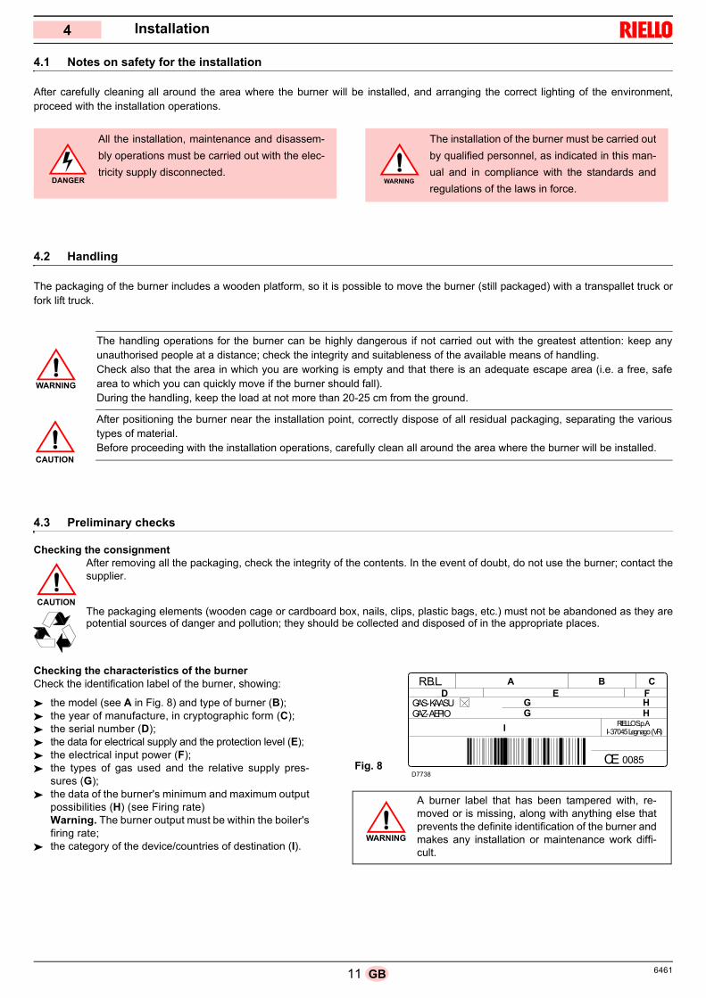
Checking the characteristics of the burner Check the identification label of the burner, showing:
the model (see A in Fig. 8) and type of burner (B); the year of manufacture, in cryptographic form (C); the serial number (D); the data for electrical supply and the protection level (E); the electrical input power (F); the types of gas used and the relative supply pres-
sures (G); the data of the burner's minimum and maximum output
possibilities (H) (see Firing rate)Warning. The burner output must be within the boiler'sfiring rate;
the category of the device/countries of destination (I).
All the installation, maintenance and disassem-
bly operations must be carried out with the elec-
tricity supply disconnected.DANGER
The installation of the burner must be carried out
by qualified personnel, as indicated in this man-
ual and in compliance with the standards and
regulations of the laws in force.WARNING
WARNING
The handling operations for the burner can be highly dangerous if not carried out with the greatest attention: keep anyunauthorised people at a distance; check the integrity and suitableness of the available means of handling.Check also that the area in which you are working is empty and that there is an adequate escape area (i.e. a free, safearea to which you can quickly move if the burner should fall).During the handling, keep the load at not more than 20-25 cm from the ground.
After positioning the burner near the installation point, correctly dispose of all residual packaging, separating the varioustypes of material.Before proceeding with the installation operations, carefully clean all around the area where the burner will be installed.
CAUTION
CAUTION
R.B.L.
GAS-KAASUGAZ-AEPIO
0085
RIELLO S.p.A.I-37045 Legnago (VR)
CEFig. 8
A burner label that has been tampered with, re-moved or is missing, along with anything else thatprevents the definite identification of the burner andmakes any installation or maintenance work diffi-cult.
WARNING
D7738
A B CED F
HGG H
I
126461 GB
Installation
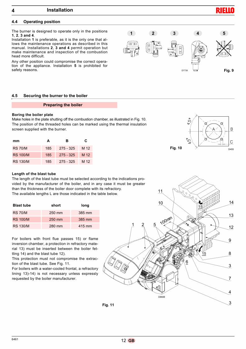
4.4 Operating position
The burner is designed to operate only in the positions1, 2, 3 and 4. Installation 1 is preferable, as it is the only one that al-lows the maintenance operations as described in thismanual. Installations 2, 3 and 4 permit operation butmake maintenance and inspection of the combustionhead more difficult.
Any other position could compromise the correct opera-tion of the appliance. Installation 5 is prohibited forsafety reasons.
4.5 Securing the burner to the boiler
2 3 4 51
D7739 Fig. 9
Preparing the boiler
100mm1 2 5
11
14
13
12
9
3
8
7
6
15
15
10
3
4
Boring the boiler plateMake holes in the plate shutting off the combustion chamber, as illustrated in Fig. 10.The position of the threaded holes can be marked using the thermal insulationscreen supplied with the burner.
mm A B C
RS 70/M 185 275 - 325 M 12
RS 100/M 185 275 - 325 M 12
RS 130/M 185 275 - 325 M 12
Fig. 10 D455
Length of the blast tubeThe length of the blast tube must be selected according to the indications pro-vided by the manufacturer of the boiler, and in any case it must be greaterthan the thickness of the boiler door complete with its refractory. The available lengths L are those indicated in the table below.
For boilers with front flue passes 15) or flameinversion chamber, a protection in refractory mate-rial 13) must be inserted between the boiler fet-tling 14) and the blast tube 12). This protection must not compromise the extrac-tion of the blast tube. See Fig. 11.For boilers with a water-cooled frontal, a refractorylining 13)-14) is not necessary unless expresslyrequested by the boiler manufacturer.
Blast tube short long
RS 70/M 250 mm 385 mm
RS 100/M 250 mm 385 mm
RS 130/M 280 mm 415 mm
Fig. 11
D8688
4
13 6461GB
Installation
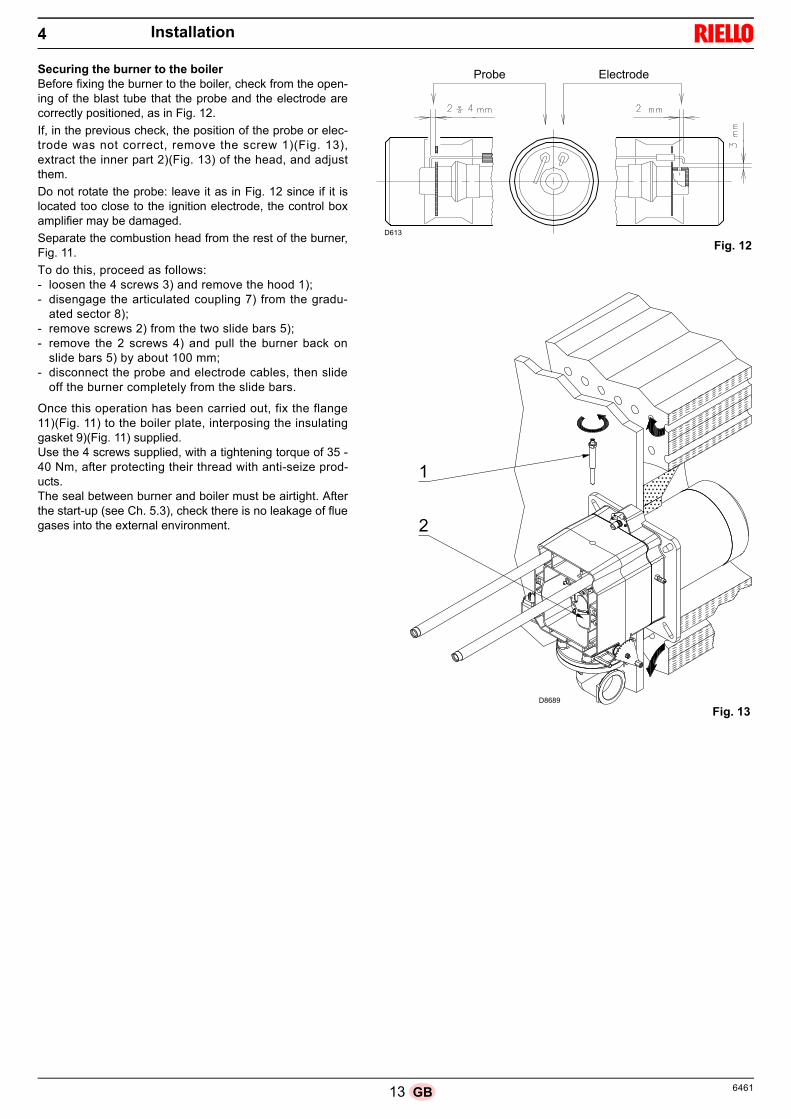
Securing the burner to the boilerBefore fixing the burner to the boiler, check from the open-ing of the blast tube that the probe and the electrode arecorrectly positioned, as in Fig. 12.
If, in the previous check, the position of the probe or elec-trode was not correct, remove the screw 1)(Fig. 13),extract the inner part 2)(Fig. 13) of the head, and adjustthem.
Do not rotate the probe: leave it as in Fig. 12 since if it islocated too close to the ignition electrode, the control boxamplifier may be damaged.
Separate the combustion head from the rest of the burner,Fig. 11.
To do this, proceed as follows:- loosen the 4 screws 3) and remove the hood 1);- disengage the articulated coupling 7) from the gradu-
ated sector 8);- remove screws 2) from the two slide bars 5);- remove the 2 screws 4) and pull the burner back on
slide bars 5) by about 100 mm;- disconnect the probe and electrode cables, then slide
off the burner completely from the slide bars.
Once this operation has been carried out, fix the flange11)(Fig. 11) to the boiler plate, interposing the insulatinggasket 9)(Fig. 11) supplied. Use the 4 screws supplied, with a tightening torque of 35 -40 Nm, after protecting their thread with anti-seize prod-ucts.The seal between burner and boiler must be airtight. Afterthe start-up (see Ch. 5.3), check there is no leakage of fluegases into the external environment.
1
2
Probe Electrode
Fig. 13
D613
Fig. 12
D8689
4

146461 GB
Installation
4.6 Combustion head adjustment
At this point of the installation, the combustion head is fixedto the boiler as shown in Fig. 13. Its adjustment is therefore particularly easy, which dependssolely on the maximum burner output.
Two adjustments of the head are foreseen: the air adjustment; the gas adjustment.
In the diagram of Fig. 16, find the notch at which to adjustboth air and central gas/air.
Air adjustmentRotate the screw 2) until the notch you have found corre-sponds with the front surface 1) of the flange.
Gas adjustmentLoosen the 4 screws) and rotate the ring nut 5) until the notchyou have found corresponds with the index 3) (Fig. 14). Block the 3 screws 4).
ExampleRS 70/M, burner output = 600 kW.According to diagram Fig. 16 the gas and air adjustments for this output are carried out on notch 4.
NOTEThe diagram indicates the optimum adjustment for a type of boiler according to Fig. 4.The adjustments indicated can be modified during the initial start-up.
ImportantTo facilitate adjustment, loosen the screw 3)(Fig. 14), adjust and then lock.
3
5
4
1
2
Fig. 15D8690
Fig. 14
CAUTION
Fig. 16
No
. Not
ches
Maximum burner output
D9079
4

15 6461GB
Installation4
Once the combustion head adjustment is completed:
reassemble the burner on the guides 3) at about 100 mmfrom the pipe coupling 4) - burner in the position shown inFig. 11;
insert the probe and electrode cables, then slide the burneras far as the pipe coupling - burner in the position shown inFig. 17;
connect the socket of the maximum gas pressure switch; refit the screws 2) on the slide bars 3);
fix the burner to the pipe coupling with the screws 1). re-couple the articulated coupling 7) to the graduated
sector 6).
4.7 Assembly of the gas train
The gas train is type-approved according to standard EN 676and is supplied separately from the burner.
The gas train can enter the burner from the right or leftside, depending on which is the most convenient, seeFig. 18.
The gas train must be connected to the gas attachment1)(Fig. 18) with the flange 2), the gasket 3) and the screws4) supplied with the burner.
The gas solenoids must be as close as possible to theburner, to ensure that the gas reaches the combustionhead within the safety time of 3 s.
Ensure that the maximum pressure necessary for theburner is included in the calibration field of the pressureadjuster.
When fitting the burner on the two guides, it isadvisable to gently draw out the high voltage cableand flame detection probe cable until they areslightly taut.CAUTION
432
5
1
6
7
Fig. 17D8691
See the accompanying instructions for theadjustment of the gas train.
WARNING
D722
Fig. 18

166461 GB
4.8 Gas feeding line
Key (Fig. 19)
1 Gas input pipe
2 Manual valve
3 Vibration damping joint
4 Pressure gauge with pushbutton cock
5 Filter
6A Includes:– Filter– working valve– safety valve– pressure adjuster
6C Includes– safety valve– working valve
6D Includes:– safety valve– working valve
7 Minimum gas pressure switch8 Leak detection device, supplied as an accessory or incorporat-
ed, based on the gas train code. In compliance with the EN 676standard, the leak detection control is compulsory for burnerswith maximum outputs over 1200 kW.
9 Gasket, for “flanged” versions only
10 Pressure adjuster
11 Train-burner adaptor, supplied separately
P2 Upstream pressure of valves/adjuster
P3 Upstream pressure of the filter
L Gas train supplied separately
L1 The responsibility of the installer
Explosion danger due to fuel leaks in the presenceof a flammable source.
Precautions: avoid knocking, attrition, sparks andheat.
Make sure that the fuel interception tap is closedbefore performing any operation on the burner.
The fuel supply line must be installed by qualifiedpersonnel, in compliance with current standardsand laws.
WARNING
WARNING
Fig. 19
20057264
MB
20062223
MBC
20062227
DMV
20062228
CB
Installation
17 6461GB
Installation
4.9 Electrical wiring
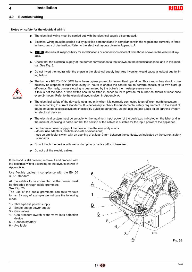
If the hood is still present, remove it and proceed withthe electrical wiring according to the layouts shown inAppendix A.
Use flexible cables in compliance with the EN 60335-1 standard.
All the cables to be connected to the burner mustbe threaded through cable grommets.See Fig. 20.The use of the cable grommets can take variousforms. By way of example we indicate the followingmode:
1 - Three-phase power supply2 - Single phase power supply3 - Gas valves4 - Gas pressure switch or the valve leak detection
device5 - Consents/safety6 - Available
Notes on safety for the electrical wiring
The electrical wiring must be carried out with the electrical supply disconnected.
Electrical wiring must be carried out by qualified personnel and in compliance with the regulations currently in force in the country of destination. Refer to the electrical layouts given in Appendix A.
declines all responsibility for modifications or connections different from those shown in the electrical lay-outs.
Check that the electrical supply of the burner corresponds to that shown on the identification label and in this man-ual. See Fig. 8.
Do not invert the neutral with the phase in the electrical supply line. Any inversion would cause a lockout due to fir-ing failure.
The burners RS 70-100-130/M have been type-approved for intermittent operation. This means they should com-pulsorily be stopped at least once every 24 hours to enable the control box to perform checks of its own start-upefficiency. Normally, burner stopping is guaranteed by the boiler's thermostat/pressure switch.If this is not the case, a time switch should be fitted in series to IN to provide for burner shutdown at least onceevery 24 hours. Refer to the electrical layouts given in Appendix A.
The electrical safety of the device is obtained only when it is correctly connected to an efficient earthing system, made according to current standards. It is necessary to check this fundamental safety requirement. In the event of doubt, have the electrical system checked by qualified personnel. Do not use the gas tubes as an earthing system for electrical devices.
The electrical system must be suitable for the maximum input power of the device,as indicated on the label and in the manual, checking in particular that the section of the cables is suitable for the input power of the appliance.
For the main power supply of the device from the electricity mains:- do not use adapters, multiple sockets or extensions;- use an omnipolar switch with an opening of at least 3 mm between the contacts, as indicated by the current safety
standards.
Do not touch the device with wet or damp body parts and/or in bare feet.
Do not pull the electric cables.
DANGER
6
A
1
B
6
5
34
6D8692
Fig. 20
4
186461 GB
Installation
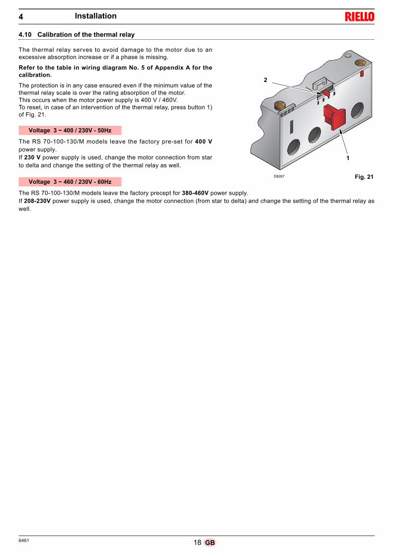
4.10 Calibration of the thermal relay
The thermal relay serves to avoid damage to the motor due to anexcessive absorption increase or if a phase is missing.
Refer to the table in wiring diagram No. 5 of Appendix A for thecalibration.
The protection is in any case ensured even if the minimum value of thethermal relay scale is over the rating absorption of the motor. This occurs when the motor power supply is 400 V / 460V.To reset, in case of an intervention of the thermal relay, press button 1)of Fig. 21.
The RS 70-100-130/M models leave the factory pre-set for 400 Vpower supply. If 230 V power supply is used, change the motor connection from starto delta and change the setting of the thermal relay as well.
The RS 70-100-130/M models leave the factory precept for 380-460V power supply. If 208-230V power supply is used, change the motor connection (from star to delta) and change the setting of the thermal relay aswell.
Fig. 21
2
1
D8267
Voltage 3 ~ 400 / 230V - 50Hz
Voltage 3 ~ 460 / 230V - 60Hz
4

19 6461GB
5.1 Notes on safety for the first start-up
5.2 Operations before start-up
Ensure that the gas supply company has carried out the supply line vent operations, eliminating air or inert gases from the piping.
Slowly open the manual valves situated upstream the gas train.
Adjust the minimum gas pressure switch (Fig. 22) to the start of the scale.
Adjust the maximum gas pressure switch (Fig. 23) to the end of the scale.
Adjust the air pressure switch (Fig. 24) to the start of the scale.
Check the gas supply pressure by connecting apressure gauge to the pressure test point 1)(Fig. 25)of the minimum gas pressure switch: it must be low-er than the maximum allowed pressure of the gastrain, as shown on the characteristics label.
Bleed the air from the piping of the gas train, con-necting a plastic tube to the pressure test point1)(Fig. 25) of the minimum gas pressure switch.Take the vent tube outside the building so you cannotice the smell of gas.
Connect two lamps or testers to the two gas line so-lenoids to check the exact moment at which voltageis supplied.This operation is unnecessary if each of the two so-lenoids is equipped with an indicator light that sig-nals voltage passing through.
The first start-up of the burner must be carried out
by qualified personnel, as indicated in this manual
and in compliance with the standards and regula-
tions of the laws in force.
Check the correct working of the adjustment, com-
mand and safety devices.
An excessive gas pressure can dam-age the components of the gas trainand lead to a risk of explosion.
Before starting up the burner, it is goodpractice to adjust the gas train so thatignition takes place in conditions of max-imum safety, i.e. with gas delivery at theminimum.
WARNING WARNING
Fig. 22
Minimum gas pressure switch
Fig. 23
Maximum gas pressure switch
Fig. 24
D3854
Air pressure switch
D3856D3855
1
E9330 Fig. 25
DANGER
WARNING
Start-up, calibration and operation of the burner5

206461 GB
Start-up, calibration and operation of the burner5
5.3 Burner start-up
Feed electricity to the burner via the disconnecting switch onthe boiler panel.Close the thermostats/pressure switches and turn the switchof Fig. 27 to position “MAN”.
As soon as the burner starts, check the direction of rotation ofthe fan blade, looking through the flame inspection window.
5.4 Burner ignition
Having completed the checks indicated in the previous head-ing, ignition of the burner should be achieved. If the motorstarts but the flame does not appear and the control box goesinto lockout, reset and wait for a new ignition attempt.If ignition is still not achieved, it may be that gas is not reach-ing the combustion head within the safety time period of 3seconds. In this case increase gas ignition delivery.The arrival of gas to the pipe coupling is shown by the pres-sure gauge. Once the burner has ignited, proceed with the global adjust-ment of the burner.
5.5 Burner adjustment
The optimum adjustment of the burner requires an analysis offlue gases at the boiler outlet. Adjust in sequence: Ignition output Maximum output Minimum output Intermediate outputs between Min. and Max Air pressure switch Maximum gas pressure switch Minimum gas pressure switch
Ignition output
According to EN 676 standard:Burners with MAX output up to 120 kWIgnition can occur at the maximum operation output level.Example: max. operation output: 120 kW max. ignition output: 120 kW
Burners with MAX output above 120 kWIgnition must occur at a lower output than the max. operationoutput.If ignition output does not exceed 120 kW, no calculations arerequired. If ignition output exceeds 120 kW, the regulatorystandard sets that the value be defined according to the con-trol box safety time "ts":for "ts" = 3s, ignition output must be equal to or less than 1/3of the max. operation output.
ExampleMAX operation output of 450 kW.The ignition output must be equal to or less than 150 kW withts = 3s.
In order to measure the ignition output: disconnect the plug-socket 6)(Fig. 5) on the ionisation
probe cable (the burner will fire and then go into lockoutafter the safety time has elapsed);
perform 10 ignitions with consecutive lockouts; on the meter, read the quantity of gas burned:
this quantity must be equal to, or lower than, the quantitygiven by the formula, for ts = 3s:
Vg: volume supplied in ignitions carried out (Sm3)
Qa: ignition delivery (Sm3/h)n: number of ignitions (10)ts: safety time (sec)
Example for gas G 20 (9.45 kWh/Sm3):ignition output 150 kW
corresponding to 15.87 Sm3/h.After 10 ignitions with their lockouts, the delivery indicated onthe meter must be equal to or less than:
Maximum output
The maximum burner output must be set within the firing raterange shown on page 7. In the above instructions we left theburner running at the MIN output. Now press the button 2)(Fig. 27) “output increase”, and keepit pressed until the servomotor has opened the air damperand the gas butterfly valve.
Make sure that the lights or testers connected tothe solenoids, or the pilot lights on the solenoidsthemselves, indicate that no voltage is present. If voltage is present, stop the burner immediatelyand check the electrical wiring.
DANGER
Fig. 26D8694
Vg =3600
Qa (max. burner delivery) x n x ts
Vg =3600
15.87 x 10 x 3= 0.132 Sm3
D791
1
Fig. 27
2

21 6461GB
Start-up, calibration and operation of the burner5
Adjustment of gas deliveryMeasure the gas delivery on the meter.A guideline indication can be calculated from the table on page38, simply read off the gas pressure on the pressure gauge, seeFig. 30 on page 21, and follow the instructions on page 38.- If delivery needs to be reduced, diminish outlet gas pressure;
if it is already very low, slightly close the VR adjustment valve.- If delivery needs to be increased, increase the adjuster outlet
gas pressure.Adjusting air deliveryProgressively adjust the end profile of cam 4)(Fig. 28) by turningthe cam adjustment screws 7).- Turn the screws clockwise to increase air delivery.- Turn the screws anticlockwise to reduce air delivery.
Minimum output
Min output must be selected within the firing rate range shownon page 7.Press the button 2)(Fig. 27) “output reduction”, and keep itpressed until the servomotor has closed the air damper and thegas butterfly valve at 65° (adjustment made in the factory).Adjustment of gas deliveryMeasure the gas delivery on the meter.- If it is necessary to reduce it, reduce slightly the angle of
cam III (Fig. 29) with small, regular movements, i.e. bring itfrom an angle of 65° to 63° - 61°....
- If it is necessary to increase it, press slightly the button “outputincrease” 2)(Fig. 27) (open by 10-15° the gas butterfly valve),increase the cam III angle (Fig. 29) with small, regular move-ments, i.e. bring it from an angle of 65° a 67° - 69°....Then press the button “output reduction” until the servomotoris in the position of minimum opening position and measuregas delivery.
NOTEThe servomotor follows the adjustment of cam III only when theangle of the cam is reduced. If it is necessary to increase theangle of the cam, you must first increase the angle of the servo-motor by means of the “output increase” key, then increase theangle of cam III, and finally bring the servomotor to the positionof MIN output, with the “output reduction” key.For any necessary adjustment of cam III, mainly for small move-ments, the specific key 10) can be used.Adjusting air deliveryProgressively adjust the end profile of cam 4) by turning the camadjustment screws 5). It is preferable not to turn the first screwsince this is used to set the air damper to its fully closed position.
Intermediate outputs
Adjustment of gas deliveryNo adjustment of gas delivery is required.Adjusting air deliveryPress slightly the button “output increase” 2)(Fig. 27) so that theservomotor rotates by 15°. Adjust the screws until optimal com-bustion is obtained. Proceed in the same way with the otherscrews. Take care that the cam profile variation is progressive.Switch the burner off with switch 1)(Fig. 27), OFF position.Release cam 4 from the servomotor by pressing and shifting but-ton 3) to the right, and check several times that by rotating cam 4forwards and backwards by hand, the movement is soft andsmooth, without jamming.Now engage cam 4) again to the servomotor by shifting button2) to the left.
As far as is possible, try not to move those screws at the ends ofthe cam that were previously adjusted for the opening of the airdamper to MAX and MIN output.Once optimum adjustment has been reached, fix it with thescrews 6).NOTEOnce you have finished adjusting outputs MAX - MIN - INTER-MEDIATE, check ignition once again: noise emission at thisstage must be identical to the following stage of operation. If younotice any sign of pulsations, reduce the ignition stage delivery.
D891
6 Servomotor7 Servomotor 1) - cam 4): constrained8 Servomotor 1) - cam 4): released9 Adjustable profile cam10 Screws for adjusting the adjustable profile11 Screws for fixing adjustment12 Screws for adjusting the end profile13 Graduated sector for gas butterfly valve14 Index for graduated sector 815 Spanner to adjust cam III
D3922
10
2
3
Fig. 28
Fig. 29

226461 GB
Start-up, calibration and operation of the burner5
Air pressure switch
Adjust the air pressure switch after having performed all otherburner adjustments with the air pressure switch set to thestart of the scale (Fig. 30).With the burner working at MIN output, insert a combustionanalyser in the stack, slowly close the suction inlet of the fan(for example, with a piece of cardboard) until the CO valuedoes not exceed 100 ppm. Slowly turn the appropriate knob clockwise until the burnergoes into lockout. Check the indication of the arrow pointing upwards on thegraduated scale. Turn the knob clockwise again, until thevalue shown on the graduated scale corresponds with thearrow pointing downwards, and so recovering the hysteresisof the pressure switch (shown by the white mark on a bluebackground, between the two arrows).Now check the correct start-up of the burner. If the burner locks out again, turn the knob anticlockwise a lit-tle bit more. During these operations it may be useful to measure the airpressure with a pressure gauge. The connection of the pressure gauge is shown in Fig. 30.The standard configuration is that with the air pressure switchconnected in absolute mode. Note the presence of a “T” con-nection, not supplied. In certain applications in strong depres-sion situations, the connection of the pressure switch doesnot allow it to change over. In this case it is necessary to con-nect the pressure switch in differential mode, applying a sec-ond tube between the air pressure switch and the fan suctionline mouth. In this case also, the pressure gauge must beconnected in differential mode, as shown in Fig. 30.
Maximum gas pressure switch
Adjust the maximum gas pressure switch after having per-formed all other burner adjustments with the maximum gaspressure switch set to the end of the scale (Fig. 31).With the burner operating at maximum output, lower adjust-ment pressure by slowly turning the relative knob anticlock-wise until the burner locks out.Turn the knob clockwise by 2 mbar and repeat the start-up ofthe burner.If the burner locks out again, turn the knob clockwise again by1 mbar.
Minimum gas pressure switch
Adjust the minimum gas pressure switch after having per-formed all other burner adjustments with the pressure switchset to the start of the scale (Fig. 32).With the burner operating at maximum output, increaseadjustment pressure by slowly turning the relative knob clock-wise until the burner locks out.Then turn the knob anticlockwise by 2 mbar and repeat burnerstart-up to ensure it is uniform.If the burner locks out again, turn the knob anticlockwiseagain by 1 mbar.
+_
+_
Connecting the pressure gauge with the pressure switch in differential mode
D3951
Connecting the pressure gauge with the pressure switch in abso-lute mode
D8695
Fig. 30
Fig. 31
D3856
D3855
Fig. 32

23 6461GB
5.6 Operation sequence of the burner
Burner start-up
• 0s: TL closed.• 5s : Start of electrical control box programme. Servomotor
starts: 130° rotation to right, until contact is made oncam I (Fig. 7).
• 35s : The air damper arrives to the MAX. output position.The fan motor starts up.Start of the pre-purging phase.
• 75s : The servomotor rotates towards the left as far as theangle set on cam III (Fig. 7) for the MIN output.
• 95s : The air damper and the gas butterfly valve adopt theMIN output position (with cam III Fig. 7 at 65°).
• 105s : Ignition electrode strikes a spark.The safety valve VS opens, along with the adjustmentvalve VR, quick opening. The flame is ignited at a lowoutput level, point A.Delivery is then progressively increased, with thevalve VR opening slowly up to MIN. output, point B.
• 108s : The spark goes out.• 115s : The starting cycle comes to an end.
STANDARD IGNITION
Steady state operation
Burner without the modulating operation kitOnce the start-up cycle is completed, the servomotor commandmoves on to the TR that controls the pressure or the tempera-ture in the boiler, point C.(The electrical control box still continues to check the presenceof the flame and the correct position of the air and gas maximumpressure switches).• If the temperature is low, so the remote control TR is closed,
the burner progressively increases the output up to the MAXvalue (tract C-D).
• If subsequently the temperature or pressure increases untilTR opens, the burner progressively decreases its output to theMIN. value (section E-F). The sequence repeats endlessly.
• The burner locks out when the heat request is less than theheat supplied by the burner at MIN. output, (section G-H. TheTL opens, and the servomotor returns to angle 0°. The airdamper closes completely to reduce heat losses to a mini-mum.
Burner with modulating operation kitSee the handbook enclosed with the adjuster.
Ignition failure
If the burner does not switch on, there is a lockout within 3s ofthe electrical supply reaching the gas valve.It may be that the gas does not arrive at the combustion headwithin the safety time of 3s. In this case increase gas ignition delivery.The arrival of the gas at the pipe coupling is shown on thepressure gauge of Fig. 36.
5.7 Burner flame goes out during operation
If the flame should accidentally go out during operation, theburner will lock out within 1s.
5.8 Stopping of the burner
The burner can be stopped by: intervening on the disconnecting switch of the electrical sup-
ply line, located on the boiler panel; removing the hood and working on the “AUT/MAN” switch of
Fig. 27.
MAX
MI N
105
105
95
7535
B
950
0
MI N
MAX
5
115
108
0 sec
M
M
A
115
135
C
D E
F G
H
D3815
Fig. 33
In the event of a burner lockout, more than twoconsecutive burner reset operations could causedamage to the installation. On the third lockout,contact the Aftersales Service. If further lockoutsor burner faults occur, interventions must only
be made by qualified, authorised personnel (as indicated inthis manual, and in compliance with the laws and regula-tions currently in force).
0 sec
0
MI N
MAX
5
105 108
M
M
35 75
95
108
108105
108
108
D3816
Fig. 34
WARNING
Start-up, calibration and operation of the burner5

246461 GB
Start-up, calibration and operation of the burner5
5.9 Measuring the ionisation current
The burner is fitted with an ionisation system to check that aflame is present. The minimum current for control box opera-tion is 6 µA. The burner provides a much higher current, so controls arenot normally required. However, if it is necessary to measure the ionisation current, dis-connect the plug-socket (2)(Fig. 35) on the ionisation probecable and insert a direct current microammeter (1)(Fig. 35) witha base scale of 100 µA. Carefully check the polarities!
5.10 Checking the air and gas pressure on the com-bustion head
5.11 Final checks (with burner operating)
Open the thermostat/pressure switch TL: Open the thermostat/pressure switch TS:the burner must stop Rotate the maximum gas pressure switch knob to the mini-
mum end-of-scale position. Rotate the air pressure switch knob to the maximum end-of-
scale position.the burner must stop in lockout Switch off the burner and disconnect the voltage. Disconnect the minimum gas pressure switch connector.the burner must not start Disconnect the ionisation probe wire.the burner must stop in lockout due to ignition failure Make sure that the mechanical locking systems on the differ-
ent adjustment devices are fully tightened.
2
1
Fig. 35
D8696
+_
+_
Fig. 36
Air pressure
Gas pressure
D8697

25 6461GB
The control box has a self-diagnostic system, which easily allows identifying the operating faults (signal: RED LED).To use this function, wait at least ten seconds from the safety lock out, and then press the reset button for a minimum of 3 sec-onds.After releasing the button, the RED LED starts flashing as shown in the diagram below.
The pulses of the LED constitute a signal spaced by approximately 3 seconds.The number of pulses will provide the information on the possible faults, according to the table below.
SIGNAL FAULT PROBABLE CAUSE SUGGESTED REMEDY
2 x blinks Once the pre-purging phase and safety time have passed, the burner goes into lock-out without the appearance of the flame
1 - The operation solenoid lets little gas through . . . . . . Increase2 - One of the two solenoid valves does not open. . . . . . Replace3 - Gas pressure too low . . . . . . . . . . . . . . . . . . . . . . . . . Increase pressure at regulator4 - Ignition electrode incorrectly adjusted . . . . . . . . . . . . Adjust, see Fig. 125 - Electrode grounded due to broken insulation. . . . . . . Replace6 - High voltage cable defective . . . . . . . . . . . . . . . . . . . Replace7 - High voltage cable deformed by high temperature. . . Replace and protect8 - Ignition transformer defective . . . . . . . . . . . . . . . . . . . Replace9 - Incorrect valve or transformer electrical wiring . . . . . Check10 - Defective control box . . . . . . . . . . . . . . . . . . . . . . . . . Replace11 - A closed valve upline the gas train. . . . . . . . . . . . . . . Open12 - Air in pipework . . . . . . . . . . . . . . . . . . . . . . . . . . . . . . Bleed air13 - Gas trains not connected or with coil blocked . . . . . . Check connections or replace coil
3 x blinks The burner does not switch on, and the lockout appears
14 - Air pressure switch in operating position . . . . . . . . . . Adjust or replace
The burner switches on, but then stops in lockout
Air pressure switch inoperative due toinsufficient air pressure:15 - Air pressure switch incorrectly adjusted . . . . . . . . . . . Adjust or replace16 - Pressure switch pressure test point pipe blocked . . . Clean17 - Head incorrectly adjusted. . . . . . . . . . . . . . . . . . . . . . Adjust18 - High pressure in the furnace . . . . . . . . . . . . . . . . . . . Connect air pressure switch to fan suction
line
Lockout during pre-purging phase
19 - Defective motor control contactor. . . . . . . . . . . . . . . . Replace(only three-phase version)
20 - Defective electrical motor . . . . . . . . . . . . . . . . . . . . . . Replace21 - Motor lockout (only three-phase version) . . . . . . . . . . Replace
4 pulses The burner switches on, but then stops in lockout
22 - Flame simulation . . . . . . . . . . . . . . . . . . . . . . . . . . . . Replace the control box
Lockout when burner stops
23 - Permanent flame in the combustion head or . . . . . . . Eliminate permanency of flame orflame simulation replace control box
6 x blinks The burner switches on, but then stops in lockout
24 - Defective or incorrectly adjusted servomotor . . . . . . . Replace or adjust
7 pulses The burner goes into lockout immediately following the appearance of the flame
25 - The operation solenoid lets little gas through. . . . . . . Increases26 - Ionisation probe Incorrectly adjusted.. . . . . . . . . . . . . Adjust it, see Fig. 1227 - Insufficient ionisation (less than 5 µA) . . . . . . . . . . . . Check probe position28 - Probe earthed . . . . . . . . . . . . . . . . . . . . . . . . . . . . . . Withdraw or replace cable29 - Burner poorly grounded . . . . . . . . . . . . . . . . . . . . . . . Check grounding30 - Phase and neutral connections inverted . . . . . . . . . . Invert them31 - Defective flame detection circuit. . . . . . . . . . . . . . . . . Replace control box
Burner locks out when shifting from minimum to maximum output and vice versa
32 - Too much air or too little gas . . . . . . . . . . . . . . . . . . . Adjust air and gas
Burner goes into lockout during operation
33 - Probe or ionisation cable earthed . . . . . . . . . . . . . . . Replace worn parts
3sSignal SignalRED LED on
press reset for 10sIntervalPress button
for > 3s
Faults - Probable causes - Solutions6

266461 GB
6.1 Normal operation / flame detection time
The control box has a further function to guarantee the correct burner operation (signal: GREEN LED permanently on).To use this function, wait at least ten seconds from the burner ignition and then press the control box button for a minimum of 3seconds.After releasing the button, the GREEN LED starts flashing as shown in the figure below.
The pulses of the LED constitute a signal spaced by approximately 3 seconds.The number of pulses will measure the probe DETECTION TIME since the opening of gas valves, according to the following table:
10 blinks The burner does not switch on, and the lockout appears
34 - Erroneous electrical wiring . . . . . . . . . . . . . . . . . . . . . Check connections
The burner goes into lockout
35 - Defective control box . . . . . . . . . . . . . . . . . . . . . . . . . Replace36 - Presence of electromagnetic disturbances in. . . . . . . Filter or eliminate
the thermostat lines37 - Presence of electromagnetic disturbance . . . . . . . . . Use the radio disturbance protection kit
No blink The burner does not start
38 - No electrical power supply . . . . . . . . . . . . . . . . . . . . . Close all switches - Check connections39 - A limiter or safety control device is open . . . . . . . . . . Adjust or replace40 - Line fuse blocked . . . . . . . . . . . . . . . . . . . . . . . . . . . . Replace41 - Defective control box . . . . . . . . . . . . . . . . . . . . . . . . . Replace42 - No gas supply. . . . . . . . . . . . . . . . . . . . . . . . . . . . . . . Open the manual valves between contactor
and train43 - Mains gas pressure insufficient . . . . . . . . . . . . . . . . . Contact your GAS COMPANY44 - Minimum gas pressure switch fails to close . . . . . . . . Adjust or replace45 - Servomotor fails to move to min. ignition position . . . Replace
The burner continues to repeat the start-up cycle, without lockout
46 - The gas pressure in the network is near the . . . . . . . Reduce the cut-in pressure of the value on which the min. gas pressure switch min. gas pressure switchgas is adjusted The sudden drop in pressure when the valve is Replace the gas filter cartridgeopened causes the temporary opening of the pressure switch itself, the valve immediately closes and the burner comes to a halt. Pressure increases again, the pressure switchcloses and the ignition cycle is repeated. And so on
Ignition with pulsa-tions
47 - Head poorly adjusted . . . . . . . . . . . . . . . . . . . . . . . . . Adjust, see Fig. 1548 - Ignition electrode incorrectly adjusted . . . . . . . . . . . . Adjust it, see Fig. 1249 - Incorrectly adjusted fan air damper: too much air . . . Adjust50 - Output during ignition phase is too high . . . . . . . . . . . Reduce
Burner does not reach maximum output
51 - Control device TR does not close . . . . . . . . . . . . . . . Adjust or replace52 - Defective control box . . . . . . . . . . . . . . . . . . . . . . . . . Replace53 - Defective servomotor . . . . . . . . . . . . . . . . . . . . . . . . . Replace
Burner stops with air damper open
54 - Servomotor defective . . . . . . . . . . . . . . . . . . . . . . . . . Replace
SIGNAL FLAME DETECTION TIME This is updated in every burner start-up.Once read, the burner repeats the start-up cycle bybriefly pressing the control box button.
WARNINGIf the result is > 2 s, ignition will be retarded.Check the adjustment of the hydraulic brake of the gasvalve, the air damper and the combustion head adjust-ment.
1 blink0.4 s
2 x blinks0.8 s
6 x blinks2.8 s
SIGNAL FAULT PROBABLE CAUSE SUGGESTED REMEDY
3sSignal SignalGREEN LED on
press reset for 10sIntervalPress button
for > 3s
Faults - Probable causes - Solutions6

27 6461GB
Maintenance
7.1 Notes on safety for the maintenance
The periodic maintenance is essential for the good operation,safety, yield and duration of the burner.It allows you to reduce consumption and polluting emissionsand to keep the product in a reliable state over time.
The maintenance interventions and the calibrationof the burner must only be carried out by qualified,authorised personnel, in accordance with the con-tents of this manual and in compliance with thestandards and regulations of current laws.
Before carrying out any maintenance, cleaning or checking op-erations:
disconnect the electricity supply from the burner bymeans of the main switch of the system;
close the fuel interception tap;DANGER
DANGER
DANGER
7
7.2 Maintenance programme
The gas combustion system should be checked at least oncea year by a representative of the Manufacturer or anotherspecialised technician.
CombustionCarry out an analysis of the flue gases. Significant differenceswith respect to the previous measurements indicate the pointswhere more care should be exercised during maintenance.
Gas leaksMake sure that there are no gas leaks on the pipes betweenthe gas meter and the burner.
Gas filterReplace the gas filter when it is dirty.
Flame inspection windowClean the glass of the flame inspection window, (Fig. 37).
Combustion headOpen the burner and make sure that all the components ofthe combustion head are:- undamaged;- not deformed due to high temperature;- free of ambient dirt or dust;- free of rusted materials;- adequately positioned. Make sure that the gas outlet holes for the start-up, on thecombustion head distributor, are free of dirt or rust deposits.If in doubt, disassemble the elbow 5)(Fig. 38).
ServomotorDisengage cam 4)(Fig. 28) from the servomotor, by pressingand shifting button 3)(Fig. 29) to the right, and cause it to turnit backwards and forwards by hand to make sure it movessmoothly. Now engage the cam again by shifting button2)(Fig. 28) to the left.
BurnerCheck for excess wear or loose screws in the mechanismscontrolling the air damper and the gas butterfly valve. Alsomake sure that the screws securing the electrical leads in theburner connections are fully tightened.Clean the outside of the burner, taking special care with thearticulated couplings and cam 4)(Fig. 28).
CombustionAdjust the burner if the combustion values found at the begin-ning of the operation do not comply with the regulations inforce or, at any rate, do not produce good combustion.Use the appropriate card to record the new combustion val-ues; they will be useful for subsequent controls.
Maintenance frequency
Checking and cleaning
D709Fig. 37

286461 GB
7.3 Opening the burner
Disconnect the electrical supply from the burner. Loosen the screws 1) and remove the hood 2). Disengage the articulated coupling 7) from the graduated
sector 8). Assemble the two extensions on the sliding bars 4). Remove the screws 3) and move the burner backwards
some 100 mm on the guides 4). Disconnect the probe andelectrode leads and then pull the burner fully back.
Now extract the gas distributor 5) after having removed thescrew 6).
7.4 Closing the burner
Push the burner up to approximately 100 mm from thepipe coupling.
Reconnect the cables and slide the burner as far as thestop.
Replace the screws 3) and carefully pull the probe andelectrode cables outwards until they are slightly taut.
Re-couple the articulated coupling 7) to the graduatedsector 8).
Disassemble the two extensions from the guides 4).
2
4
6
5
1
8
7
1
3
D8698
Fig. 38
Maintenance7

29 6461GB
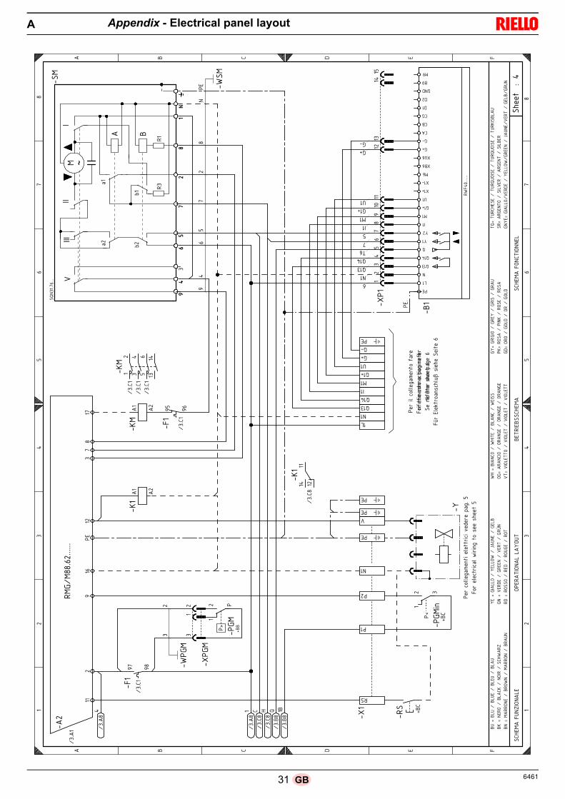
Index of layouts
2 Indication of references
3 Functional layout RMG/M
4 Functional layout RMG/M
5 Electrical wiring that the installer is responsible for (50 Hz)
6 Electrical wiring that the installer is responsible for (60 Hz)
7 Functional layout RWF40...
1
2
Sheet no.
/1.A1
Co-ordinates
Indication of references
Appendix - Electrical panel layoutA
Wiring layout keyA - Electrical control boxB - Filter to protect against radio disturbanceB1 - Output regulator RWF40BA - Input in current DC 4...20 mABA1 - Input in current DC 4...20 mA to modify remote set-
pointBP - Pressure probeBP1 - Pressure probeBR - Remote setpoint potentiometerBT1 - Thermocouple probeBT2 - Probe Pt100, 2 wiresBT3 - Probe Pt100, 3 wiresBT4 - Probe Pt100, 3 wiresBTEXT - External probe for climatic compensation of the set-
pointBV - Input in voltage DC 0...10VBV1 - Input in voltage DC 0...10V to modify remote setpointCN1 - Ionisation probe connectorF1 - Fan motor thermal relayH - Remote lockout signalIN - Burner manual stop switchION - Ionisation probeK1 - Clean contacts output relay burner switched on
K2 - Clean contacts output relay burner lockoutKM - Motor contact makerMV - Fan motorPA - Air pressure switchPE - Burner earthPGMin - Minimum gas pressure switchPGM - Maximum gas pressure switchQ1 - Three-phase disconnecting switchQ2 - Single phase disconnecting switchRS - Remote reset switchS1 - Off / automatic / manual selectorS2 - Power increase - power reduction selectorSM - ServomotorTA - Ignition transformerTL - Limit thermostat/pressure switchTR - Adjustment thermostat/pressure switchTS - Safety thermostat/pressure switchX1 - Main terminal supply boardXPGM - Maximum gas pressure switch connectorXP1 - Socket for kitXRWF - Terminal board RWF40Y - Gas adjustment valve + gas safety valveYVPS - Valve leak detection device

306461 GB
Appendix - Electrical panel layoutA
���������
�
� ��
�����������
�
��
�
�
��
�
�� �
�
��
��
��
��
��
�
�
�
��!�"��#$%&'$�(�
����)�����(��
�$'"�*+%��(�
�'����)�'���(�
��
,�� �-�
.��
��
��
�
��
�� ��
�� �
�
��
��
��
�/
(�
0�
��
�/
(�
0�
. , 1 � �
. , 1 � �
�,�� ��2�3�-����� ��
�
�� ����-���
��-����4-2�
.�����.��,�� �� ��
���
�,�� ��-�,��-������ ��
�/���/��
��
��5� (6�
��
�� /7��(889�� :..
�;�6� ��
� /
( �
�/�.��/�./
<0 <�
<( <�
�/�./
��
(
�/
�
��� ����� ��
����
����
:.,
:.,
�
��%�:.
,
:.,
�
:.,
/�+
=$*�'$>?
��
�
��� ����
�5�(
����
��
��
�
� �
.
./��
���/
��
��
��
��
( �
�
,��/ ��
��
,0�/ ��
���
��
�@
/ ��
��
:.,
,
�-�,
��
�
�+�A
�
�+�A�/
:
�
�+�A
�0
./��
���/
�
�
�/�.�
��
���/
�
/
/�/��
��/�,�
�.�/�,�
�/�,�
��/�,�
,�/�,�
.2�B�.�2���.�2����.��2���.�2
.��B����-���.�,�����-������,���3
4��B�����-���4���-����C2��������.
���B����1���������������������D�
�1�B��-��-�����1����-2������-�
���B�.��,-����
�������.��,����
����
-�B��
�,�-���-�
������-�
������-�
���
��B���-����-�����-��������-��������-����
�4B������-������4������������
2��B��-�
�����������-������-�
�1B�-�-����-�1���-�����-�1
� B��2�,��������2� 2-�������2� 2-�������2����.�2
��B������-�����������������������.��
��4�B�����-�
���1����4���-����������C2�������������.�
��2�
.��B� ��-�����.�-����� ��-����.�
2�
��
2���
2���
��
:..
����
�-1
2�-
�5
31 6461GB
Appendix - Electrical panel layoutA
���
������
�
�� �
�����������
���
���
�� �
��
��
���
���
�
�� �
���
�
���
���
���
���
���
���
��
�����
�
�
����
���
����
�
��
��
�
�
��
��
�
� ! " # �
� ! " # �
�!$#
���%&
'�(&
)#
(�#�
*�(&
)�)
�(%
*�#
*��#��
�!$#
�
�!$#
���(&
!*�(&&
#)
����
�����
�����!
���!�
$���!�
+�����
�������
��
��
,�!
��- ,�!
�
��.�/011�
234��
����1���.�/��5�6
�.��73
2���
�0.��1�/�.�/31�8
�.��2��0�9��
�9��
����
���!�
: :�
�� �
��;
�
��
�
�
: �
��
&�
�#
�#
�
��#
�#
�
���!�
�� ���
�
�
��.��1�/011�
234��
�0�<3.�
.�<�.�4��
�0�3�732
��3��
�0.�����/0��
�/��0�
�.�<�.
�0����
�9��
����
���.=<=.�.�3>?
�732
���
�@.�#1�A
�.03
�9/�1>B�
9���
����
�����
�)&��
�
���!�
���!�
���!�
� � � ��
� � ��
���!�
:� :�
+��+������ �,%� , ��#
�#�
:
����
C�C
3�3
:�
��
�
�
�&
:�
�� ��
�� &��
+��� �
+��� �
*�� ��
�� � �
�
�� ��
��� �
��� :
�,� �D
� %�� ��
�
,� ��
�� �� ��
�&
&��#
� ����
E
�%�F��)%
����)%
#����)#%����)
%��
�F�&#�
(����)
!���
�&(������!$
��'
�#�F� �))(����
#))(
���
�G%&
#��� #)�
&�F��
#�"#
��� �#
#&��
��#�
*��� �H
&�"
�F��(�
�(��
��#"
����(%
#��
��(*
�$�F���&!
(����
$�*#
����)
&!��
��#���
( F��
&!�(��
�(�
& #���(�
& #���(�
& #
�*F
���()#**
(����
�()#*����
�()#*����
�()#**
�F� �
� �(��
� �#
���
� ������ �
%��
F��(
���
���&�����(�
#����(�
"
F�(�
(��� ()
"���(���� ()
"
*+F�*%
�!$#
�#��
�*%�
+%(
��#���*%�
+%(
��#���*%�
����
)%
��F��
#&*(
�����)�#�
���
� #&
*�����)�#
� &
�#F� �))(�
�#�
"#��
��#))(
�� �
##&���G%&
#��#�
*��� #)��
�%&
�&�F��
��
(&#�����(
�&����
��
(&��
���
%&
,��
�+&�
�� ����
�#
)�
&
+��
+��
+
��
�
��
��
�,
%�
��,
���
��
���
�%�
,
�
!
!�
!
"�
"
&"
�:
�:
����
D������

326461 GB
Appendix - Electrical panel layoutA
���
������
�
��
�
�� �
����
���
��
�
�
�������
�����
�����������
����
���
� ��
�� ��
�
��
�
�� ��
�� ��
�����!
�������
"�!
�#��$%
&�
' �
!��(�)
�!�
���)�
��
*+��
'
��
*+��
��
*+��
!��*�)�
�
����
�
���
�!� �
!��
)��
'���
����
����
���
!"'�
�
��"�!
�!�
,������
�"��$
*���
������
����
����
��! �
�
�
�!�
������
��!�
)���
����
!���
-
./0���
���� *����
�./0� ���
��� *��
���
������
��!�
)���
����
!���
./0��1��� *����
�
�$
*�
�2
(+
*�
�2
(+
� 3 � � � '
� 3 � � � '
����
� ����
������
��!�����
��,!
���
���4����
����
���
!���
���!
�������
����
����
����
��3�
����
����
�!��
���!
����
�$�5
�������
����
����
���
,!��
,�6,
'5$!
��!�
���!
�����
���7��
��!��,
���'
'���
,7��
�!�
�4����
����
���
,!
������
����
������
!!,�
��!�
��� �
����
�!����
���
���!
������
����
�
"��$�
���
� �
����
�$�!
�����"
���$
�$��
����
���
��
� '
�
�
�3,
3�
�8
�3�
�3�
�3�
3�
�
�
�
*)�)
������
�) *��
���$
%
*
�*
�*
��
��
��
)�)
����� *�
����$
%
���/�
+��9
0-�
..:
�� �� �
� �������
�4����
�!!,
���,
!��� �
7���
$�!�
��,�
�$����!�
����
���
��
���'���
������
���� �
����
$�!�
���$
����
$���
�!��
����
��";$�
��
� '
�
�
�
�
�*)��
�� *��
���$
%
*
�*
�*
��
��
���/�
+��9
0-�
..:
�
�
)��
��� *�
����$
%
�
�
2��/�
��9
-��.
.:
-��.
.:
��
*
���/�
+��9
+��/�
2��9
-��..:
-��.
.:
���/�
+��9
���/�
���9
-��..:
-��.
.:
2��/�
��9
���
�/0
���
�/0
���
<���
�/0
���
�/0
���
�/0
�������
�������
����
6���
����
������
!� �
����
!���
����
���6
��!
"'�
�
�������
��'�!"
'����,
��,�
���"
�!�!
� ,�
���
!����
����
����
�������
�4��
������
����
��,�
!� ,
����
,!��
���,
����
����!"
'��
3������3
���
����
�����,
� �!
� ��
!�!"
'��
�
-
�
�3�
�� �*��
�2
�
�+�2 �
�
�(,�����
����
����
���,
����
���
�� �
�'!�
����
�����
��,�
���
�=���/9��( �
����
�3�
�+��=���/9�
��>!�3��$���,� �����3!����!�3���� ��3!,��,!3,!��!�������,�
3������3!,�����!�
�
��!�
������
����
���!
��!�
�
�,�
��
�'5!
�!����
����
���
!�'������������ ��'���������,�7���� �6'�������� $���� ��
* '��������������� ���
�*
�
??
??
?
3,�@�3�,
�)�3�,
��)�3��,�)�3��
,3�
�@���!
��)�3��
���)
����!�)���$
"�!6
���@� ������)��
����
"�)
�A�,�
��)� ��3
��@��
�!��
�)� !�
���)
���!
��)� !5
�!�
�@�!��
���)
�!��
�)�!�,
��)
�!��
"$�@�3����
��)�"
$���
�)�3��
���)
�"����
� @��!�
�����)
��!�
� ��)��!�
� ��)��!�
� �
��@
��������
��)��
������)��
������)��
������
�@� !
� ���)
� !�
��)
� !���)� !�
,��
@�!�
���)
������)�!��
��)�!��
� �
@��!
��)� ��
��)��!�)� ��
�
��@��,
!�$�
���)
��,!
�,����
�)��,!
�,����
�)��,!
���3
��,
�!@��!
����
�)������!
�)��
! ��
��)����3�
! �
��@� �����)
��!
���)
������
") !
����)�A�,�
�)��!
��)� ��3)
!,�
3��@��
�!!
����)�3!�
"��)��
�!!
���)
�3!�
,�
�+
�2
�
�+�(
�23�
���
�*
*
��
�!
*��
�
�
�
�"
," ,
�
,�"
�
, "
�"
," ,
�
,�"
�
, "
�"
," ,
�
,�"
�
, "
??

33 6461GB
Appendix - Electrical panel layoutA
���������
�
��
�
�� �
�������
��
�
�
�����������������������������
� ��!
�� ��!
�
��
�
�� ��!
�� ��!
�����"�������#�"�$��%&'
( �
"��)�*�
"����*�
!+��
����
(
!+��
����
!+��
����
"��+�*�
�
����
�
��
�"� �"� *��
(���
��������
��
"#(��
��#�"�"� ,����� �#
��%
+�������� ��� ��
��
��" �
�
�
�"�
� ������"�*� �����"���
-
./0�������!+�����
./0�!������!+�����
� ������"�*� �����"���
./0��1���!+�����
�%
!
+�
��
)2
!
+�
��
)2
� 3 � � � (
� 3 � � � (
����� ��� ��������
"�������,"
������4�� �
�������
"������"
�������
�����
������3�
�� �
�����"
�����"
�� �
�%�5��
�����
�� �
�������,"
��,�
6,(5%"
� "�
���"
���� ��
�7����"��,
���((���,7���"��4�� �
�������,"
�����
������� ��""
,���
"����
����
�"����
��� ���"�����������
#��%�����
�����%
�"�����#
���%
�%��
���������
� (
�
�
3,
3
�8
�3�
�3�
�3�
3�
�!
�!
�
+* *
����+2�*!!�����%&
+
�+
�+
��
��
��
* *
�����!!�����%&
���/�
2��9
!0-�..:
�� �
�!� ������4�� �
�"",
���,"���
7���
%�"�
��,�
�%����"����������
���(������� �����
����
%�"�
���%�
��%�
���"����
����#;%��
� (
�
�
�!
�!
�+*����!!�����%&
+
�+
�+
��
��
���/�
2��9
!0-�..:
�
�
*�����!!�����%&
�!
���/�
!��9
-��..:
-��..:
��
+
���/�
2��9
2��/�
���9
!-��..:
-��..:
���/�
2��9
���/�
!���9
!-��..:
-��..:
���/�
!��9
���
�/0
���
�/0
���
<���
�/0
���
�/0
���
�/0
� �����
�������
����
6��
����������"� �
����
"�������
�� 6
��"#(��
� �������(�"#
(����,
��,�
���#
�"�"� ,����
"����
����
���
� ������4����
����
���
��,�"� ,
����,"
�����,
����
���"#
(��
3����� 3
� ����������,
�"
� ��"�"#
(��
�
-
�!
�3�
��!�+��
��
�!
�2�� �
�
�),�����
���
����
���,
����
�����
��("����� �
�����,�
���
�=���/9��) �
� �
�3�
�2��=���/9�
��>"�3��%���, �����3"� �"�3���� ��3",��,"3," �"�������,�
3������3",�����"�!
��"�
�����
�������"
��"��
�,�
�
�(5"
�"�� �
� ��
���
"�(�������� ��� ��(���������,�7���� �6(�������� %���� ��
+ (��������������� ���
�+
??
??
?
3,�@�3�,�*�3�,��*�3��,�*�3��,
3��@� �"��*�3�����*� ��"�*���%#�"6
���@� ������*������#�*�A�, ��*� ��3
�@���"���*� "�� �*���"��*� "5
"��@�"�����*�"���*�"�, ��*�"��
#%�@�3�� ���*�#
%����*�3�� ��*�#
����
� @��"�
����*��"�
��*��"�
��*��"�
�
��@����������*��������*��������*��������
�@� "� ���*� "���*� "���*� "�
,��@�"���
�*��� ��*�"����*�"���
�@��"��*� ����*��"�*� ���
��@��,"�%����*��,"�,
�����*��,"�,
�����*��,"���3��,
�"@��" � ���*������"�*��" � ��*����3�"
��@� �����*
��"���*������#* "�� �*�A�, �*��"��*� ��3*
",
3 �@���""� ��*�3"�# �*���""� �*�3"�
,
�2
��
�2�)
��3�
��
�+
!
! +
��
�"
!
+��
�!
�
�#
,#!,!
�!
,�#
�!
,!#!
�#
,#!,!
�!
,�#
�!
,!#!
�#
,#!,!
�!
,�#
�!
,!#!
??

346461 GB
Appendix - Electrical panel layoutA
���������
�
���
���
���
��������
���
�
�
��
�������
�
��
��
���
�
�����
��� !������ ��"�!���"
��
��
�#$�!���"��"�$�� ��%�&�'()��*****
��(
���
�
��
��+
��
��
��, �!
��
���������-����������"�$�
�!
��
���������-����� �#$�!���"��"�$�� ��%�������������
��
�.
��
�.
��
���������-����������"���"�$��!"#�������"���%���
(
+,
/'
�0
(
+,
/'
�0
! � # � �
! � # � �
��%� !��$"1��"!���� �,)***
� �,)***�����!���"!���!-�$�
��������%� !�� �,)***
��%� !���"����""���� �,)***
����
�
�23�����4��3��3�
)5,6���()7!��)5(6��).�#�
" (
��&+ +&, ,
�' /
�� '
�0 �
�!�8#�8#��
� 0
9
:� )
$ ��8#�8#��
������������;������,0/
�::"#
:� (
:� +
:�
��������4������4��;�������<23���
#��(,.�=�+)7!
:�
�
9
� 9
:�
%
"
&�'()��*****
:"
)=).:�
:�
� $
'
�
�
�'
:�
:�
��
(
��
,****()7!
���))
%
%
�#�#
��
��
� �'
)�()7!��,�()7!�#�
�
)�()7!��,�()7!�#�
� '
:�
�$'
)�.��)�).�#�
$
)�.��)�).�#�
:�
� '
�
��
�
��
$�>��$�=��$��=���$�=��!$
?�>�"����=��!�?�=�"����=���% !�1
-��>�:�!����=�-���� �=�@!$"��=�:��
:"�>�.��#��=�:���"�=�.����=�:�A"
�#�>�������=���#�=���$:��=����
%�>��!"���=� %����=��!"��=� ����
�:>�!�!"����=���!":��=���!":��=���!":�
.�>�.��������=�.������=�.������=�.������
:->�:��:���=�:��-�=�:����=�:�!$
�?>����!�=���"?�=������=����!
:#>�����=�:��#�=����=�:��#
�&>��$��%����=��$�&$�����=��$�&$�����=��$�?���!$
��>�!�:�"���=����.���=�!�:�"��=������
:"-�>�:�!���=.��#��=�-���� =:���"�=�@!$"�=.����=�:��=:�$"
"�>� !���"��=��� "�=� !���"�=��!$"
��
� �,)*********
�
"
&+
&
&,
-
-(
�
:�
$
��
��
'
�'
�$'
:�
:�
�!
�
�:
#
#(
:"#
9
9
����7���3���
�3�<�2����7�����3��
��<�<����������7�7����
���(�B��������3��
��<�<�����
��������7����
��<�<����������7�7����
���+�B��������3��
#������B�����3�������3��3�
���C��B�����3�������3��3�
#������B���������4���3��3�
���C��B���������4���3��3�

35 6461GB
Output power regulator kit for modulating operation
With the modulating operation, the burner continually adapts the power to the request for heat, ensuring great stability for the parametercontrolled: temperature or pressure. Two components should be ordered: • the output power regulator to install on the burner; • the probe to install on the heat generator.
Output power regulator with signal 4-20 mA, 0-10V
Two components should be ordered: • the analogue signal converter;• the potentiometer.
Potentiometer kit for the indication of load position
RMG to PC interface adapter kit
Soundproofing chamber
Long Head Kit
Kit for LPG operation
Parameter to be checked Probe Output Regulator
Adjustment field Type Code Type CodeTemperature - 100...+ 500°C PT 100 3010110
RWF40 3010414Pressure
0...2.5 bar0...16 bar
Output probe4...20mA
30102133010214
Burner Potentiometer Analogue Signal Converter
RS 70-100/M - RS 130/MType Code Type Code
ASZ... 3010416 E5202 3010415
Burner Kit code
RS 70-100/M - RS 130/M 3010416
Burner Kit code
RS 70-100/M - RS 130/M 3002719
Burner Kit code TypeReduction of
noise average
RS 70-100/M - RS 130/M 3010404 C4/5 10 [dB(A)]
Burner Kit code Standard head lengthHead length obtained
with the kit
RS 70/M 3010117 250 mm 385 mmRS 100/M 3010118 250 mm 385 mmRS 130/M 3010119 280 mm 415 mm
BurnerCombustion
headKit code
Obtainable output with the Kit
RS 70/MTC 20008175
200/470 ÷ 930 kWTL 20008176
RS 100/MTC 20008177
300/700 ÷ 1340 kWTL 20008178
RS 130/MTC 20008179
300/920 ÷ 1600 kWTL 20008180
Appendix - Accessories (on request)B

366461 GB
Kit for TOWN GAS operation - not EC type-approved
Spacer kit
Continuous purging kit
Vibration reduction kit (for flame inversion boilers)
Radio disturbanceprotection kit
If the burner is installed in places particularly subject to radio disturbance (emission of signals exceeding 10 V/m) owing to the presenceof an INVERTER, or in applications where the length of the thermostat connections exceeds 20 metres, a protection kit is available as aninterface between the control box and the burner.
Gas trains in compliance with EN 676
Please refer to manual.
BurnerCombustion
headKit code
RS 70/MTC
3010286TL
RS 100/MTC
3010287TL
RS 130/MTC
3010288TL
Burner Kit code Thickness
RS 70-100/M - RS 130/M 3010129 135 mm
Burner Kit code
RS 70-100/M - RS 130/M 3010094
BurnerCombustion
headKit code
RS 70/MTC
3010201TL
RS 100/MTC
3010202TL
RS 130/MTC 3010373TL 3010374
Burner Kit code
RS 70-100/M - RS 130/M 3010386
Appendix - Accessories (on request)B

37 6461GB
Appendix - Gas supply pressureC
The table show minimum load losses along the gas supply linedepending on the maximum burner output operation.
The values shown in the tables refer to:• Natural gas G 20 PCI 9.45 kWh/Sm3 (8.2 Mcal/Sm3)• Natural gas G 25 PCI 8.13 kWh/Sm3 (7.0 Mcal/Sm3)
Column 1Load loss at combustion head.Gas pressure measured at the test point 1)(Fig. 39), with:• Combustion chamber at 0 mbar;• Burner working at maximum output;• Combustion head adjusted according to the diagram of
Fig. 16.
Column 2Load loss at gas butterfly valve 2)(Fig. 39) with maximum open-ing: 90°.
NOTETo know the approximate output at which the burner is operatingat its maximum:- Subtract the combustion chamber pressure from the gas pres-
sure measured at test point 1)(Fig. 39).- Find, in the table relating to the burner concerned, column 1,
the pressure value closest to the result you want.- Read off the corresponding output on the left.
Example with natural gas G 20 - RS 100/M• Maximum output operation• Ring nut 2)(Fig. 15) adjusted as in the diagram of (Fig. 16)• Gas pressure at test point 1)(Fig. 39) = 8 mbar• Pressure in combustion chamber = 2.5 mbar
8 - 2.5 = 5.5 mbarA pressure of 5.5 mbar, column 1, corresponds in the table toan output of 900 kW.This value serves as a rough guide; the effective output mustbe measured at the gas meter.
NOTETo know the required gas pressure at test point 1)(Fig. 39), setthe MAX output required from the burner operation:- Find the nearest output value in the table for the burner in
question.- Read, on the right, column 1, the socket pressure 1)(Fig.
39).- Add this value to the estimated pressure in the combustion
chamber.
Example with natural gas G 20 - RS 100/M• Required burner maximum output operation: 900 kW• Ring nut 2)(Fig. 15) adjusted as in the diagram of (Fig. 16)• Gas pressure at output of 900 kW = 5.5 mbar• Pressure in combustion chamber = 2.5 mbar
5.5 + 2.5 = 8 mbarpressure required at test point 1)(Fig. 39).
Fig. 39S8883
Mo
d.
kW1
p (mbar)2
p (mbar)
G 20 G 25 G 20 G 25
RS
70
/M
470 4.2 5.7 0.4 0.5
500 4.6 6.3 0.5 0.5
550 5.3 7.2 0.6 0.7
600 6.0 8.2 0.7 0.8
650 6.7 9.1 0.8 0.9
700 7.4 10.1 0.9 1.1
750 8.5 11.8 1.0 1.2
800 9.6 13.4 1.2 1.4
850 10.8 15.1 1.3 1.6
900 12.1 16.9 1.5 1.8
930 12.9 17.9 1.6 1.9
RS
10
0/M
700 3.1 4.6 0.7 1.0
750 3.7 5.5 0.8 1.1
800 4.3 6.4 0.9 1.2
850 4.9 7.3 1.0 1.4
900 5.5 8.2 1.1 1.6
950 6.2 9.0 1.2 1.8
1000 6.8 9.9 1.3 1.9
1050 7.3 10.7 1.5 2.1
1100 7.9 11.6 1.6 2.4
1150 8.4 12.4 1.8 2.6
1200 9.1 13.5 1.9 2.8
1250 9.9 14.8 2.1 3.0
1300 10.8 16.1 2.3 3.3
1340 11.4 17.1 2.4 3.5
RS
130
/M
920 4.5 7.0 1.3 2.0
950 4.7 7.4 1.4 2.1
1000 5.1 7.9 1.5 2.3
1050 5.5 8.5 1.7 2.5
1100 5.9 9.1 1.8 2.8
1150 6.2 9.6 2.0 3.1
1200 6.6 10.2 2.2 3.3
1250 7.0 10.8 2.4 3.6
1300 7.4 11.3 2.6 3.9
1350 7.8 11.9 2.8 4.2
1400 8.2 12.8 3.0 4.5
1450 8.6 13.8 3.2 4.9
1500 9.0 14.7 3.4 5.2
1550 10.2 15.6 3.6 5.6
1600 11.4 16.6 3.9 5.9
1605 11.5 16.7 3.9 6.0

386461 GB
Appendix - Firing rate on basis of air densityD
The firing rate of the burner shown in the manual is valid for aroom temperature of 20°C and an altitude of 0m above sea lev-el (barometric pressure around 1013 mbar).
It may be that a burner has to operate with combustive air at ahigher temperature and/or higher altitudes.
The heating of the air and the increase in altitude produce thesame effect: the expansion of the air volume (i.e. the reductionof its density).
The delivery of the burner fan remains essentially the same,but the oxygen per m3 of air, and the thrust (discharge head)of the fan are reduced.
It is therefore important to know if the maximum output re-quested from the burner at a determinate combustion chamberpressure remains within the firing rate of the burner even withthe changed temperature and altitude conditions.To check it, proceed as follows:
1 -Find the corrective factor F (relating to the air temperatureand altitude of the system) in the table alongside.
2 -Divide the output Q required from the burner by F to obtainthe equivalent output Qe:
3 -In the firing rate of the burner, mark the work point identifiedby:Qe = equivalent outputH1 = pressure in combustion chamberpoint A that must remain within the firing rate (Fig. 40).
4 -Trace a vertical line from point A, Fig. 40, and find the max-imum pressure H2 of the firing rate.
5 -Multiply H2 by F to obtain the maximum lowered pressureH3 of the firing rate
If H3 is greater than H1, as in Fig. 40, the burner can producethe delivery requested.If H3 is less than H1, it is necessary to reduce the burner out-put. The reduction in output is accompanied by a reduction inthe combustion chamber pressure:Qr = reduced outputH1r = reduced pressure
Example, 5% reduction in output:
Qr = Q x 0.95
H1r = H1 x (0.95)2
With the new values - Qr and H1r - repeat steps 2 - 5.
Warning: the combustion head should be adjusted in relation to theequivalent output Qe.
Qe = Q : F (kW)
H3 = H2 x F (mbar)
H1r = H1 x ( )Qr
Q
2
Qe kg/h
mbar
Fig. 40
Qe
AH1
H2H3
D388 kW
mbar
AltitudeAverage
barometric pressure
F
Air temperature °C
m. above sea level
mbar 0 5 10 15 20 25 30 40
0100200300400500600700800900
10001200140016001800200024002800320036004000
10131000989978966955944932921910898878856836815794755714675635616
1.0871.0731.0611.0501.0371.0251.0131.0000.9880.9770.9640.9420.9190.8970.8750.8520.8100.7660.7240.6820.661
1.0681.0541.0421.0311.0181.0070.9950.9820.9710.9590.9460.9250.9020.8810.8590.8370.7960.7530.7110.6690.649
1.0491.0351.0241.0131.0000.9890.9770.9650.9540.9420.9300.9090.8860.8660.8440.8220.7820.7390.6990.6570.638
1.0311.0171.0060.9950.9830.9720.9600.9480.9370.9260.9140.8930.8710.8510.8290.8080.7680.7260.6870.6460.627
1.0131.0000.9890.9780.9660.9550.9440.9320.9210.9100.8980.8780.8560.8360.8150.7940.7550.7140.6750.6350.616
0.9960.9830.9720.9620.9500.9390.9280.9160.9060.8950.8830.8630.8420.8220.8010.7810.7420.7020.6640.6240.606
0.9800.9670.9560.9460.9340.9230.9130.9010.8910.8800.8680.8490.8280.8080.7880.7680.7300.6900.6530.6140.596
0.9480.9360.9260.9160.9040.8940.8840.8720.8620.8520.8410.8220.8010.7830.7630.7430.7070.6680.6320.5940.577

1 6461E
Declaracion
Declaración de conformidad según ISO / IEC 17050-1
Fabricante: RIELLO S.p.A.
Dirección: Via Pilade Riello, 737045 Legnago (VR)
Producto: Quemadores de gas con aire soplado
Modelo: RS 70/MRS 100/MRS 130/M
Estos productos están conformes con las siguientes Normas Técnicas:
EN 676
EN 12100
y según lo dispuesto por las Directivas Europeas:
GAD 2009/142/CE Directiva Aparatos de Gas
MD 2006/42/CE Directiva Máquinas
LVD 2006/95/CE Directiva Baja Tensión
EMC 2004/108/CE Compatibilidad Electromagnética
Estos productos están marcados como se indica a continuación:
La calidad está garantizada mediante un sistema de calidad y management certificado según UNE EN ISO 9001.
Legnago, 03.09.2014 Director generalRIELLO S.p.A. - Dirección Quemadores
Director Investigación y DesarrolloRIELLO S.p.A. - Dirección Quemadores
Ing. U. Ferretti Ing. R. Cattaneo
CE-0085AQ0708 Clase 1 (EN 676)

26461 E
Índice
Sección Pág.
1 Informaciones y advertencias generales 31.1 Información sobre el manual de instrucción 31.2 Garantía y responsabilidades 3
2 Seguridad y prevención 42.1 Introducción 42.2 Adiestramiento del personal 4
3 Descripción técnica del quemador 53.1 Designación quemadores 53.2 Modelos disponibles 53.3 Categorías del quemador - países de destino 53.4 Datos técnicos 63.5 Datos eléctricos 63.6 Peso quemador 63.7 Dimensiones 73.8 Campos de trabajo 83.9 Componentes del quemador 93.10 Material suministrado en dotación 93.11 Caja de control de la relación aire/combustible 103.12 Servomotor 10
4 Instalación 114.1 Notas sobre la seguridad para la instalación 114.2 Traslado 114.3 Controles preliminares 114.4 Posición de funcionamiento 124.5 Fijación del quemador a la caldera 124.6 Regulación del cabezal de combustión 144.7 Montaje de la rampa de gas 154.8 Línea alimentación de gas 164.9 Conexiones eléctricas 174.10 Calibración del relé térmico 18
5 Puesta en funcionamiento, calibración y funcionamiento del quemador
19
5.1 Notas sobre la seguridad para la primera puesta en funcionamiento
19
5.2 Operaciones antes de la puesta en funcionamiento 195.3 Arranque del quemador 205.4 Encendido del quemador 205.5 Regulación del quemador 205.6 Secuencia de funcionamiento del quemador 235.7 Apagado del quemador en funcionamiento 235.8 Parada del quemador 235.9 Medición de la corriente de ionización 245.10 Control de la presión del aire y del gas en el
cabezal de combustión24
5.11 Controles finales (con el quemador funcionando) 24
6 Anomalías - Causas - Soluciones 256.1 Funcionamiento normal/Tiempo de detección
llama26
7 Mantenimiento 277.1 Notas sobre la seguridad para el mantenimiento 277.2 Programa de mantenimiento 277.3 Apertura del quemador 287.4 Cierre del quemador 28
A Apéndice - Esquema cuadro eléctrico 29
B Apéndice - Accesorios (sobre demanda) 35
C Apéndice - Presión de alimentación de gas 37
D Apéndice - Campo de trabajo en función de la densidad del aire
38
3 6461E
Informaciones y advertencias generales1
1.1 Información sobre el manual de instrucción
IntroducciónEl manual de instrucción entregado como suministro del quema-dor:
constituye parte integrante y fundamental del producto yno se lo debe separar del quemador; por lo tanto debe con-servarse con cuidado para toda necesidad de consulta ydebe acompañar al quemador incluso en caso de entregar-se a otro propietario o usuario, o en caso de transferenciaa otra instalación. En caso de daño o extravío debe solici-tarse otro ejemplar al Servicio Técnico de Asistencia
de la Zona;
fue realizado para uso de personal calificado;
suministra importantes indicaciones y advertencias sobrela seguridad de la instalación, la puesta en funcionamien-to, el uso y el mantenimiento del quemador.
Simbología utilizada en el manualEn algunas partes del manual figuran señales triangulares dePELIGRO. Prestar mucha atención a las mismas ya que indi-can una situación de peligro potencial.
Los peligros pueden ser de 3 niveles, como se indica a conti-nuación.
Otros símbolos
Abreviaturas utilizadasCap. CapítuloFig. FiguraPág. PáginaSec. SecciónTab. Tabla
Entrega de la instalación y del manual de instrucciónEn ocasión de la entrega de la instalación es necesario que: El manual de instrucción sea entregado por el proveedor
de la instalación al usuario, con la advertencia de que di-cho manual debe ser conservado en el local de la instala-ción del generador de calor.
En el manual de instrucción figuran:el número de matrícula del quemador;la dirección y el número de teléfono del Centro de Asisten-cia más cercano;
El proveedor de la instalación informe con precisión al usua-rio acerca de:- el uso de la instalación, - eventuales pruebas adicionales necesarias de realizarantes de la activación de la instalación,- el mantenimiento y la necesidad de controlar la instala-ción por lo menos una vez al año por parte de un encarga-do de la empresa fabricante o de otro técnicoespecializado.Para garantizar un control periódico, se recomien-da estipular un Contrato de Mantenimiento.
¡Máximo nivel de peligro!Este símbolo distingue a las operacionesque si no se ejecutan correctamente causa-rán graves lesiones, muerte o riesgos alargo plazo para la salud.
Este símbolo distingue a las operacionesque si no se ejecutan correctamentepodrían causar graves lesiones, muerte oriesgos a largo plazo para la salud.
Este símbolo distingue a las operaciones quesi no se ejecutan correctamente podrían cau-sar daños a la máquina y/o a las personas.
PELIGROS GENERALES
PELIGRO
ATENCIÓN
PRECAUCIÓN
Este símbolo distinguirá las operacionesque si no se ejecutan correctamente causa-rán descargas eléctricas con consecuen-cias mortales.
DEFENSA DEL MEDIO AMBIENTEEste símbolo suministra indicaciones parausar la máquina respetando el medioambiente.
Este símbolo distingue a una lista.
PELIGRO COMPONENTES CON TENSIÓN
PELIGRO
1.2 Garantía y responsabilidades
garantiza sus productos nuevos a partir de la fecha de ins-talación según las normativas vigentes y/o de acuerdo con el con-trato de venta. Verificar, en el momento de la primera puesta enfuncionamiento, que el quemador esté en buen estado y completo.
La inobservancia de todo lo descrito en este manual,la negligencia operativa, una instalación incorrecta yla realización de modificaciones no autorizadasserán causa de anulación por parte de , de lagarantía que la misma otorga al quemador.
En particular, los derechos a la garantía y a la responsabilidadcaducarán, en caso de daños a personas y/o cosas cuando losdaños hayan sido originados por una o más de las siguientescausas: instalación, puesta en funcionamiento, uso y
mantenimiento del quemador incorrectos; uso impropio, erróneo e irracional del quemador; intervención de personal no habilitado; realización de modificaciones no autorizadas en el aparato; uso del quemador con dispositivos de seguridad defectuosos,
aplicados en forma incorrecta y/o que no funcionen;
instalación de los componentes adicionales no probadosjunto con el quemador;
alimentación del quemador con combustibles no aptos; defectos en la instalación de alimentación del combustible; uso del quemador aunque se compruebe algún error y/o
anomalía; reparaciones y/o revisiones realizadas en forma incorrecta; modificación de la cámara de combustión mediante intro-
ducción de elementos que impidan el normal desarrollo dela llama implementada en fábrica;
insuficiente e inadecuada vigilancia y cuidado de loscomponentes del quemador que están mayormente sujetosa desgaste;
uso de componentes no originales , sean éstosrecambios, kits, accesorios y opcionales;
causas de fuerza mayor.
además declina toda y cualquier responsabilidadpor la inobservancia de todo cuanto mencionado en el pre-sente manual.
ATENCIÓN

46461 E
Seguridad y prevención2
2.1 Introducción
Los quemadores fueron diseñados y fabricados enconformidad con las normas y directivas vigentes, aplicandolas regulaciones técnicas de seguridad conocidas y previen-do todas las situaciones de peligro potenciales.Sin embargo es necesario considerar que usar el aparato demodo imprudente y sin experiencia puede causar situacionesde peligro mortales para el usuario o terceros, además de da-ños al quemador y a otros bienes. La distracción, imprevisióny demasiada confianza a menudo son causa de accidentes;como pueden serlo el cansancio y la somnolencia.
Es conveniente tener en cuenta lo siguiente: El quemador debe destinarse sólo al uso para el cual fue
expresamente previsto. Todo otro uso debe considerarseimpropio y por lo tanto peligroso.
En detalle:puede ser aplicado a calderas de agua, de vapor, de acei-te diatérmico, y a otros dispositivos expresamente previs-tos por el fabricante;el tipo y la presión del combustible, la tensión y la frecuenciade la corriente eléctrica de alimentación, los caudales míni-mos y máximos con los cuales está regulado el quemador, lapresurización de la cámara de combustión, las dimensionesde la cámara de combustión, la temperatura ambiente, de-ben estar comprendidos dentro de los valores indicados enel manual de instrucción.
No está permitido modificar el quemador para alterar lasprestaciones ni los destinos.
El uso del quemador se debe realizar en condiciones deseguridad técnica irreprochables. Los eventuales inconve-nientes que puedan comprometer la seguridad se debeneliminar inmediatamente.
No está permitido abrir o alterar los componentes del que-mador, excepto aquellas partes previstas en el manteni-miento.
Se pueden sustituir exclusivamente las piezas previstaspor el fabricante.
2.2 Adiestramiento del personal
El usuario es la persona, entidad o empresa que compra lamáquina y cuya intención es usarla con el fin para el cual fueconcebida. Suya es la responsabilidad de la máquina y deladiestramiento de aquellos que trabajen en ella.El usuario: está obligado a confiar la máquina exclusivamente a per-
sonal calificado y adiestrado para ese fin; es responsable de tomar todas las medidas necesarias para
evitar que personas no autorizadas tengan acceso a la má-quina;
está obligado a informar a su personal en forma conve-niente sobre la aplicación y observancia de las prescripcio-nes de seguridad. Para ello se responsabiliza de quecualquiera dentro de sus atribuciones tenga conocimientode las instrucciones para el uso y de las prescripciones deseguridad;
deberá informar a la empresa fabricante en caso de quecompruebe defectos o mal funcionamiento de los sistemasde prevención de accidentes, además de toda situación desupuesto peligro.
El personal siempre deberá usar los medios de protecciónindividual previstos por la legislación y cumplir todo lomencionado en el presente manual.
El personal deberá atenerse a todas las indicaciones depeligro y de precaución señalizadas en la máquina.
El personal no deberá emplear su propia iniciativa en ope-raciones o intervenciones que no sean de su competencia.
El personal tiene la obligación de manifestar a su superiortodo problema o situación de peligro que pudiera crearse.
El montaje de las piezas de otras marcas o eventuales mo-dificaciones pueden cambiar las características de la má-quina y por lo tanto perjudicar la seguridad operativa. Porlo tanto, la empresa fabricante declina toda y cualquier res-ponsabilidad por los daños que pudieran surgir causadospor el uso de piezas no originales.

5 6461E
Descripción técnica del quemador3
3.1 Designación quemadores
3.2 Modelos disponibles
3.3 Categorías del quemador - países de destino
Designación Tensión Código Tensión Código
RS 70/M TC 3 ~ 400 / 230V - 50Hz 3789600 - 3789610 3 ~ 380 / 220V - 60Hz 3787082RS 70/M TL 3 ~ 400 / 230V - 50Hz 3789601 - 3789611 3 ~ 380 / 220V - 60Hz 3787083RS 100/M TC 3 ~ 400 / 230V - 50Hz 3789700 - 3789710 3 ~ 380 / 220V - 60Hz 3787282RS 100/M TL 3 ~ 400 / 230V - 50Hz 3789701 - 3789711 3 ~ 380 / 220V - 60Hz 3787283RS 130/M TC 3 ~ 400 / 230V - 50Hz 3789800 - 3789810 3 ~ 380 / 220V - 60Hz 3787482RS 130/M TL 3 ~ 400 / 230V - 50Hz 3789801 - 3789811 3 ~ 380 / 220V - 60Hz 3787483
País de destino Categoría gas
BE I2E(R) - I3CY - CZ - MT I3B/P
LU - PL II2E3B/PDE II2ELL3B/PFR II2Er3PIT II2H3
ES - GB - IE - PT II2H3AT - CH - CZ - DK - EE - FI - GR - HU - IE
IS - LT - NO - SE - SI - SK - TR II2H3B/P
NL II2L3B/P
Serie: R
Tamaño
Combustible: Gas natural
Gasóleo
Gasóleo / Metano
Regulación:
Sistema de control llama:FS1
FS2
Estándar (1 stop cada 24 h)
Funcionamiento continuo (1 stop cada 72 h)
Alimentación eléctrica del sistema:3/400/50
3/230/50
Tensión auxiliares:230/50/60
110/50/60
R S 100 M TC
Emisión: C01 o... Clase 1 EN676
BLU o BLU Clase 3 EN676
FS1 3/400/50 230/50/60
DESIGNACIÓN BASE
DESIGNACIÓN AMPLIADA
3N / 400V / 50Hz
3N / 230V / 50Hz
230V / 50-60Hz
110V / 50-60Hz
Aceite pesado
E Leva electrónica
EV Leva electrónica con velocidad variable (con Inverter)
P Válvula proporcional aire/gas
BP 2 llamas (gasóleo) / Válvula proporcional (gas)
M Leva mecánica
S
L
LS
N
Cabezal: TC Cabezal estándarTL Cabezal largo
C02 o MZ Clase 2 EN676
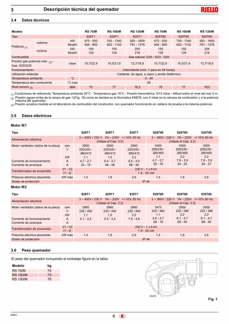
66461 E
Descripción técnica del quemador3
3.4 Datos técnicos
(1) Condiciones de referencia: Temperatura ambiente 20°C - Temperatura gas 15°C - Presión barométrica 1013 mbar - Altitud sobre el nivel del mar 0 m.
(2) Presión aguas arriba de la rampa de gas 1)(Fig. 19) como se declara en la Normativa EN676, con 0 mbar en la cámara de combustión y a la potenciamáxima del quemador.
(3) Presión acústica medida en el laboratorio de combustión del constructor, con quemador funcionando en caldera de prueba a la máxima potencia.
3.5 Datos eléctricos
Motor IE1
Motor IE2
3.6 Peso quemador
Modelo RS 70/M RS 100/M RS 130/M RS 70/M RS 100/M RS 130/M
Tipo 828T1 829T1 830T1 828T80 829T80 830T80
Potência (1)
máximakW
Mcal/h470 - 930404 - 800
700 - 1340602 - 1152
920 - 1600791 - 1376
470 - 930404 - 800
700 - 1340602 - 1152
920 - 1600791 - 1376
mínimakW
Mcal/h150129
150129
254218
150129
150129
254218
Combustible Gas natural: G20 - G23 - G25Presión gas potencia máx. (2) -
Gas: G20/G25mbar 15,7/22,9 15,5/21,9 12,7/18,9 15,7/22,9 15,5/21,9 12,7/18,9
Funcionamiento Intermitente (mín. 1 paro en 24 horas)Utilización estándar Calderas: de agua, a vapor y aceite diatérmicoTemperatura ambiente °C 0 - 40Temperatura aire comburente °C max 60Nivel sonoro (3) dBA 75 77 78,5 75 77 78,5
Tipo 828T1 829T1 830T1 828T80 829T80 830T80
Alimentación eléctrica3 ~ 400V / 230 V 1N ~ 230V +/-10% 50 Hz
(Véase el Cap. 3.2)3 ~ 380V / 220 V 1N ~ 220V +/-10% 60 Hz
(Véase el Cap. 3.2)Motor ventilador (datos de la placa)
Corriente de funcionamientoCorriente de arranque
rpmV
kWAA
2800220/240 - 380/415
1,14,7 - 2,733 - 19
2830220/240 - 380/415
1,56,4 - 3,748 - 28
2860220/240 - 380/415
2,28,5 - 4,968 - 39
3400208/230 -380/460
1,14,7 - 2,728 - 16
3500208/230 - 380/460
2,27,8 - 3,943 - 25
3500208/230 -380/460
2,27,8 - 3,964 - 37
Transformador de encendidoV1 - V2I1 - I2
230 V - 1 x 8 kV1 A - 20 mA
Potencia eléctrica absorbida kW máx 1,4 1,8 2,6 1,4 1,8 2,6Grado de protección IP 44
Tipo 828T1 829T1 830T1 828T80 829T80 830T80
Alimentación eléctrica3 ~ 400V / 230 V 1N ~ 230V +/-10% 50 Hz
(Véase el Cap. 3.2)3 ~ 380V / 220 V 1N ~ 220V +/-10% 60 Hz
(Véase el Cap. 3.2)Motor ventilador (datos de la placa)
Corriente de funcionamientoCorriente de arranque
rpmV
kWAA
2860230 / 400
1,14,1 - 2,4
2860230 / 400
1,55,5 - 3,4
2860230 / 400
2,27,9 - 4,6
3475220 / 380
1,14,6 - 2,728 - 18
3500220 / 380
2,28,1 - 4,769 - 40
3500220 / 380
2,28,1 - 4,769 - 40
Transformador de encendidoV1 - V2I1 - I2
230 V - 1 x 8 kV1 A - 20 mA
Potencia eléctrica absorbida kW máx 1,4 1,8 2,6 1,4 1,8 2,6Grado de protección IP 44
El peso del quemador incluyendo el embalaje figura en la tabla.
Modelo kg
RS 70/M 70RS 100/M 73RS 130/M 76
Fig. 1D9078

7 6461E
Descripción técnica del quemador3
3.7 Dimensiones
Las dimensiones del quemador se muestran en la Fig. 2.Tener en cuenta que para inspeccionar el cabezal de com-bustión, el quemador debe abrirse desplazando la parte pos-terior por las guías.Las dimensiones del quemador abierto están indicadas porla cota I.
D731
(1) Tubo llama: corto-largo
mm A B C D E F (1) G H I (1) L M N O
RS 70/M 511 296 215 555 840 250-385 179 430 1161-1296 214 134 221 2”RS 100/M 527 312 215 555 840 250-385 179 430 1161-1296 214 134 221 2”RS 130/M 553 338 215 555 840 280-415 189 430 1161-1296 214 134 221 2”
Fig. 2

86461 E
Descripción técnica del quemador3
3.8 Campos de trabajo
Los gráficos se han obtenido con calde-ras de prueba especiales, según lanorma EN 676.En la Fig. 4 se indica el diámetro y longi-tud de la cámara de combustión deprueba.
EjemploPotencia 756 kW (650 Mcal/h):diámetro 60 cm,longitud 2 m.
El acoplamiento estará asegurado si lacaldera tiene la homologación CE; paracalderas o hornos con cámaras de com-bustión de dimensiones muy diferentes alas indicadas en el gráfico de la Fig. 4 serecomienda realizar controles prelimina-res.
Fig. 4
Long
itud
de la
cám
ara
de c
ombu
stió
n -
m
D715
RS 100/M
Fig. 3
RS 70/M
RS 130/M
La potencia máxima debe elegirse dentro del área A delgráfico.
La potencia mínima no debe ser inferior al límite mínimodel gráfico:
AtenciónEl campo de trabajo se ha calculado considerando una tem-peratura ambiente de 20 °C, una presión barométrica de1.013 mbar (aprox. a 0 m s.n.m.) y con el cabezal de com-bustión regulado como se indica en el Cap. 4.6.
Pre
sión
en
la c
ámar
a de
co
mbu
stió
n –
mb
arP
resi
ón e
n la
cám
ara
de
com
bust
ión
– m
bar
Pre
sión
en
la c
ámar
a de
co
mbu
stió
n –
mb
ar

9 6461E
Descripción técnica del quemador3
3.9 Componentes del quemador
19
21
17
A
123161514
9
26
10
13 1120
24
18
25
12
23
4
22
5 86 7
1 Cabezal de combustión2 Electrodo de encendido3 Tornillo regulación cabezal de com-
bustión4 Presostato gas de máxima5 Servomotor, para el control de la vál-
vula de mariposa del gas y, medianteuna leva de perfil variable, el registrodel aire.Cuando el quemador está parado, elregistro del aire está completamentecerrado para reducir al mínimo la dis-persión térmica de la caldera debido altiro de la chimenea que toma aire de laboca de aspiración del ventilador.
6 Conector macho-hembra cable sondade ionización
7 Alargadores para guías 15)8 Contactor motor y relé térmico con pul-
sador de desbloqueo9 Un interruptor para:
funcionamiento automático - manual -paroUn pulsador para:aumento - disminución de potencia
10 Regleta de conexión eléctrica11 Conexiones eléctricas a cargo del ins-
talador12 Caja de control con piloto luminoso de
bloqueo y pulsador de desbloqueo13 Visor llama14 Presostato aire (tipo diferencial)15 Guías para abertura del quemador e
inspección del cabezal de combustión
16 Toma de presión gas y tornillo fijacióncabezal
17 Toma de presión aire18 Sonda para controlar la presencia de lla-
ma19 Registro de aire20 Entrada aire del ventilador21 Tornillos fijación del ventilador al
manguito22 Conducto entrada gas23 Válvula mariposa gas24 Brida para fijación a la caldera25 Disco estabilizador de llama26 Brida para aplicar el regulador de po-
tencia RWF40
Fig. 5
D8687
A
Vista desde A

10 6461E
3.10 Material suministrado en dotación
3.11 Caja de control de la relación aire/combustible
IntroducciónLa caja de control RMG/M 88.62... montada en los quemado-res serie RS, está proyectada para el control y el arranque dequemadores de gas de aire soplado con funcionamiento inter-mitente.De acuerdo con:- Norma técnica EN676 (quemadores de gas)- Norma técnica EN298 (aparatos de gas)
Datos técnicos
3.12 Servomotor
El servomotor regula simultáneamente el registro del airemediante la leva de perfil variable y la válvula de mariposa delgas. El servomotor gira a 130° en 42 segundos.
No modificar la regulación efectuada enfábrica de las 5 levas con que va dotado; veri-ficar simplemente que las levas estén regula-das del siguiente modo:
Leva I: 130°Limita la rotación máxima.Con el quemador funcionando a la MÁX potencia, la válvulade mariposa del gas debe estar completamente abierta: 90°.
Leva II: 0°Limita la rotación mínima.
Con el quemador parado, el registro de aire y la válvula demariposa del gas deben estar cerrados: 0°.
Leva III: 30°Regula la posición de encendido y de la potencia MÍN.
Leva V: solidaria con la leva III.
El quemador se entrega con: Brida para rampa de gas Junta para brida 4 tornillos para fijar la brida M8x25 Junta aislante Alargadores 7) per guías 15): sólo para versiones TL
N° 4 tornillos para fijar la brida del quemador a la calderaM12x35
Manual de instrucciones Lista de recambios
Todas las operaciones de instalación, manteni-miento y desmontaje deben ser realizadas en su to-talidad con la red eléctrica desconectada.Para evitar daños a cosas o personas, no abra nimodifique la caja.
La instalación de la caja debe ser realizada porpersonal habilitado, de acuerdo con las normas ydisposiciones de ley vigentes.
Alimentación eléctrica AC 220.....240V +10% / -15%
Frecuencia 50.....60 Hz +/- 6%Fusible interno T6,3H250VFuncionamiento inferior del valor nominal de alimentacióneléctricaValor mínimo de funcionamiento al disminuir la alimentación eléctrica desde el valor nominal
aproximadamente AC 160 V
Valor mínimo de funcionamiento al aumentar la alimentación eléctrica hacia el valor nominal
aproximadamente AC 175 V
Carga máxima de los contactos:Salida de alarmaAlimentación nominalCorriente máxima
AC 230 V, 50/60 Hz0,5 A
Fig. 6
PELIGRO
ATENCIÓN
Longitud cables permitidaTermóstatoPresostato aireCPI Presostato gas Detector de llama Desbloqueo a distancia
máx. 20 m a 100 pF/mmáx. 1 m a 100 pF/mmáx. 1 m a 100 pF/mmáx. 20 m a 100 pF/mmax. 1 mmáx. 20 m a 100 pF/m
Par de apriete tornillos M4 máx. 0,8 Nm
ATENCIÓN
D3859
Fig. 7

11 6461E
Instalación4
4.1 Notas sobre la seguridad para la instalación
Después de realizar una cuidadosa limpieza en toda el área de la instalación del quemador y de proveer una correcta iluminación delambiente, proceder con las operaciones de instalación.
4.2 Traslado
El embalaje del quemador incluye la plataforma de madera, por lo tanto es posible trasladar el quemador incluso cuando todavía estáembalado, con carretilla transpalet o carretilla elevadora de horquillas.
4.3 Controles preliminares
Control del suministroDespués de quitar todo el embalaje, asegurarse de que el contenido esté en buen estado. En caso de dudas no utilizar elquemador y dirigirse al proveedor.
Los elementos del embalaje (jaula de madera o caja de cartón, clavos, grapas, bolsas de plástico, etc.) no deben dejarseabandonados porque son potenciales fuentes de peligro y de contaminación, sino que se deben recoger y depositar en unlugar preparado para ese fin.
Control de las características del quemadorControlar la placa de identificación del quemador, en lacual figuran:
el modelo (véase A en la Fig. 8) y el tipo de quemador(B);
el año de fabricación criptografiado (C); el número de matrícula (D); los datos de la alimentación eléctrica y el grado de protec-
ción (E); la potencia eléctrica absorbida (F); los tipos de gas a usar y las correspondientes presio-
nes de alimentación (G); los datos de la potencia mínima y máxima posibles del
quemador (H) (véase Campo de trabajo)Atención. La potencia del quemador debe estar com-prendida dentro del campo de trabajo de la caldera;
la categoría del aparato/países de destino (I).
Todas las operaciones de instalación, manteni-
miento y desmontaje deben ser realizadas en su
totalidad con la red eléctrica desconectada.PELIGRO
El quemador debe ser instalado por personal ha-
bilitado según todo lo indicado en el presente
manual y en conformidad con las normas y dis-
posiciones de ley vigentes.ATENCIÓN
ATENCIÓN
Las operaciones de traslado del quemador pueden ser muy peligrosas si no se realizan con la máxima atención: manteneralejados a los no involucrados en la actividad; controlar que los medios a disposición sean aptos y estén en buen estado.Debe comprobarse además, que la zona en la cual se trabaja esté libre de obstáculos y que exista una zona de escapesuficiente, o sea una zona libre y segura a la cual poder desplazarse rápidamente en caso de que el quemador se cayera.Durante el traslado mantener la carga a no más de 20-25 cm del piso.
Después de colocar el quemador cerca de la instalación, eliminar correctamente todos los residuos del embalajediferenciando los diferentes tipos de materiales.Antes de proceder con operaciones de instalación, realizar una cuidadosa limpieza en toda el área destinada a lainstalación del quemador.PRECAUCIÓN
PRECAUCIÓN
R.B.L.
GAS-KAASUGAZ-AEPIO
0085
RIELLO S.p.A.I-37045 Legnago (VR)
CEFig. 8
La alteración, eliminación, la ausencia de la placade identificación del quemador y todo cuanto nopermita la correcta identificación del quemador y di-ficulte los trabajos instalación y mantenimiento.ATENCIÓN
D7738
A B CED F
HGG H
I

126461 E
Instalación
4.4 Posición de funcionamiento
El quemador está preparado exclusivamente para elfuncionamiento en las posiciones 1, 2, 3 y 4. Es conveniente escoger la instalación 1 puesto que esla única que permite el mantenimiento tal como descritoa continuación en este manual. Las instalaciones 2, 3 y4 permiten el funcionamiento pero complican las opera-ciones de mantenimiento y de inspección del cabezalde combustión.Cualquier otro posicionamiento debe considerarse com-prometedor para el funcionamiento correcto del apa-rato. La instalación 5 está prohibida por motivos deseguridad.
4.5 Fijación del quemador a la caldera
2 3 4 51
D7739 Fig. 9
Preparación de la caldera
100mm1 2 5
11
14
13
12
9
3
8
7
6
15
15
10
3
4
Perforación de la placa calderaTaladrar la placa de cierre de la cámara de combustión tal como se indica en la Fig. 10.Puede marcarse la posición de los orificios roscados utilizando la junta aislante quese suministra con el quemador.
mm A B C
RS 70/M 185 275 - 325 M 12
RS 100/M 185 275 - 325 M 12
RS 130/M 185 275 - 325 M 12
Fig. 10 D455
Longitud de tubo llamaLa longitud del tubo llama debe seleccionarse de acuerdo con las indicacio-nes del fabricante de la caldera y, en cualquier caso, debe ser mayor que elespesor de la puerta de la caldera completa, con el material refractarioincluido. Las longitudes L disponibles son las indicadas en la tabla de abajo.
Para calderas con pasos de humos delanteros 15)o con cámara de inversión de llama, colocar unaprotección de material refractario 13) entre elrefractario de la caldera 14) y el tubo de llama 12). Esta protección debe permitir el desplazamientodel tubo de llama. Véase Fig. 11.En calderas con frente refrigerado por agua, no esnecesario el revestimiento refractario 13)-14)salvo que lo indique expresamente el fabricantede la caldera.
Tubo llama corto largo
RS 70/M 250 mm 385 mm
RS 100/M 250 mm 385 mm
RS 130/M 280 mm 415 mm
Fig. 11
D8688
4

13 6461E
Instalación
Fijación del quemador a la calderaAntes de fijar el quemador a la caldera, controlar desde laapertura del tubo llama, si la sonda y el electrodo estáncorrectamente colocados como en la Fig. 12.
Si en el control anterior, la posición de la sonda o del elec-trodo no era la correcta, sacar el tornillo 1)(Fig. 13), extraerla parte interior 2)(Fig. 13) del cabezal y proceder a su cali-bración.
No hacer girar la sonda, sino dejarla como en la Fig. 12; yaque si se sitúa demasiado cerca del electrodo de encen-dido podría dañar el amplificador de la caja de control.
Luego separar el cabezal de combustión del resto del que-mador, Fig. 11.
Para lograr esto proceder de la siguiente manera:- aflojar los 4 tornillos 3) y sacar la tapa 1);- desenganchar la articulación 7) del sector
graduado 8);- desenroscar los tornillos 2) de las dos guías 5);- Desenroscar los dos tornillos 4) y desplazar el quema-
dor por las guías 5) unos 100 mm;- Desconectar los cables de la sonda y del electrodo y a
continuación extraer por completo el quemador de lasguías.
Una vez realizada esta eventual operación, fijar la brida11)(Fig. 11) a la placa de la caldera, intercalando la protec-ción aislante 9)(Fig. 11) suministrada. Utilizar los 4 tornillos suministrados, con un par de torsiónde 35 ÷ 40 Nm, después de proteger la rosca con produc-tos antigripado.La junta quemador-caldera debe ser hermética. despuésdel arranque (véase Cap. 5.3) controlar que no haya esca-pes de humos hacia el ambiente exterior.
1
2
Sonda Electrodo
Fig. 13
D613
Fig. 12
D8689
4

146461 E
Instalación
4.6 Regulación del cabezal de combustión
En este punto de la instalación el cabezal de combustión sefija a la caldera como en la Fig. 13. Es particularmente fácil su regulación, la cual depende única-mente de la potencia máxima del quemador.
En el cabezal se deben efectuar dos regulaciones: regulación del aire; regulación del gas.
Buscar en el diagrama de la Fig. 16 la muesca con la cualregular tanto el aire como el gas/aire central.
Regulación aireGirar el tornillo 2) hasta que coincida la muesca encontradacon el plano delantero 1) de la brida.
Regulación gasAflojar los 4 tornillos ) y girar la tuerca 5) hasta que coincidala muesca hallada con el índice 3) (Fig. 14). Bloquear los 3 tornillos 4).
EjemploRS 70/M, potencia = 600 kW.Del diagrama de la Fig. 16 se desprende que para esta potencia las regulaciones del gas y del aire se deben efectuar en lamuesca 4.
NOTAEl gráfico muestra una regulación óptima para un tipo de calderas según la Fig. 4.Las regulaciones indicadas se podrán modificar durante la puesta en funcionamiento.
ImportantePara facilitar la regulación, aflojar el tornillo 3)(Fig. 14), regular y después bloquear.
3
5
4
1
2
Fig. 15D8690
Fig. 14
PRECAUCIÓN
Fig. 16
N°
Mue
sca
s
Potencia máxima quemador
D9079
4

15 6461E
Instalación4
Finalizada la regulación del cabezal de combustión:
volver a montar el quemador en las guías 3) a unos100 mm del manguito 4) - quemador en la posición quemuestra la Fig. 11;
conectar el cable de la sonda y el cable del electrodo y luegodeslizar el quemador hasta el manguito, quemador en laposición ilustrada en la Fig. 17;
conectar la toma del presostato gas de máxima; volver a colocar los tornillos 2) en las guías 3);
fijar el quemador al manguito utilizando los tornillos 1). volver a enganchar la rótula 7) en el sector graduado 6).
4.7 Montaje de la rampa de gas
La rampa de gas está homologada según la norma EN676 y se suministra por separado del quemador.
La rampa puede llegar por la derecha o por la izquierda,según convenga. Ver Fig. 18.
La rampa de gas va acoplada a la conexión de gas1)(Fig. 18), mediante la brida 2), la junta 3) y los tornillos4), que se suministran con el quemador.
Las electroválvulas del gas deben estar lo más cercaposible del quemador, para asegurar la llegada del gas alcabezal de combustión en el tiempo de seguridad de 3 s.
Asegurarse de que la presión máxima que necesita elquemador esté comprendida dentro del campo de calibra-ción del regulador de presión.
En el momento de cerrar el quemador en lasguías, es conveniente tirar suavemente haciaafuera del cable de alta tensión y del de la sondadetección de llama para controlar la presencia dellama hasta que estén ligeramente tensados.
PRECAUCIÓN
432
5
1
6
7
Fig. 17D8691
Para la regulación de la rampa de gas,véaselas instrucciones que acompañan a lamisma.ATENCIÓN
D722
Fig. 18

166461 E
4.8 Línea alimentación de gas
Leyenda (Fig. 19)
1 Conducto entrada gas
2 Válvula manual
3 Junta antivibratoria
4 Manómetro con válvula de pulsador
5 Filtro
6A Comprende:– filtro– válvula de funcionamiento– válvula de seguridad– regulador de presión
6C Comprende:– válvula de seguridad– válvula de funcionamiento
6D Comprende:– válvula de seguridad– válvula de funcionamiento
7 Presostato gas de mínima
8 Control de estanqueidad, suministrado como accesorio o inte-grado, según el código de rampa de gas. Según la norma EN676 el control de estanqueidad es obligatorio para quemado-res con potencia máxima superior a 1200 kW.
9 Junta, sólo para versiones “embridadas”
10 Regulador de presión
11 Adaptador rampa-quemador, suministrado por separado
P2 Presión antes de las válvulas/regulador
P3 Presión antes del filtro
L Rampa de gas, suministrada por separado
L1 A cargo del instalador
Riesgo de explosión a causa de derrame de com-bustible en presencia de fuentes inflamables.
Precauciones: evitar golpes, roces, chispas, calor.
Verificar el cierre del grifo de interceptación delcombustible, antes de efectuar cualquier tipo de in-tervención en el quemador.
La instalación de la línea de alimentación del com-bustible debe ser efectuada por personal habilitado,de acuerdo con las normas y las disposiciones deley vigentes.
ATENCIÓN
ATENCIÓN
Fig. 19
20057264
MB
20062223
MBC
20062227
DMV
20062228
CB
Instalación4

17 6461E
Instalación
4.9 Conexiones eléctricas
Si todavía está colocada, retirar la tapa y realizar lasconexiones eléctricas según los esquemas del Apén-dice A.
Utilizar cables flexibles según norma EN 60 335-1.
Todos los cables que se conecten al quemadordeben pasar por los pasacables.Véase Fig. 20.El uso de los pasacables se puede realizar de for-mas diferentes; a modo de ejemplo, indicamos laforma siguiente:
1 - Alimentación trifásica2 - Alimentación monofásica3 - Válvulas de gas4 - Presostato gas o dispositivo para el control de
estanqueidad de las válvulas5 - Permisos / seguridades6 - A disposición
Notas sobre la seguridad para las conexiones eléctricas
Las conexiones eléctricas se deben realizar sin alimentación eléctrica.
Las conexiones eléctricas deben ser realizadas por personal calificado y según las normas vigentes en el país de destino. Tomar como referencia los esquemas eléctricos que figuran en el Apéndice A.
declina toda responsabilidad por modificaciones o conexiones diferentes a las que figuran en los esque-mas eléctricos.
Controlar que la alimentación eléctrica del quemador corresponda a la que figura en la placa de identificación y en el presente manual. Véase Fig. 8.
No invertir el neutro con la fase en la línea de alimentación eléctrica. La inversión provocaría una parada en blo-queo por falta de encendido.
Los quemadores RS 70-100-130/M han sido homologados para funcionar de modo intermitente Esto significa quedeben pararse “por Norma” al menos una vez cada 24 horas para permitir que la caja de control efectúe un controlde su eficacia en el arranque. Normalmente la parada del quemador está asegurada por el termostato/presostatode la caldera.Si no fuese así, debería colocarse en serie con el interruptor IN, un interruptor horario que parase el quemador almenos una vez cada 24 horas. Tomar como referencia los esquemas eléctricos que figuran en el Apéndice A.
La seguridad eléctrica de aparato se alcanza solamente cuando el mismo está conectado correctamente a una instalación de puesta a tierra eficaz, realizada como está previsto por las normas vigentes. Es necesario controlar este requisito de seguridad fundamental. En caso de dudas, el personal habilitado deberá realizar un cuidadoso control de la instalación eléctrica. No utilizar tubos de gas como instalación de puesta a tierra de aparatos eléctri-cos.
La instalación eléctrica debe ser apta para la potencia máxima absorbida del aparato, indicada en la placa y en el manual, asegurando en especial que la sección de los cables tenga la capacidad para la potencia absorbida del aparato.
Para la alimentación general del aparato de la red eléctrica:- no usar adaptadores, tomas múltiples, alargadores;- prever un interruptor omnipolar con apertura entre los contactos de al menos 3 mm, como lo prevén las normativas
de seguridad vigentes.
No tocar el aparato con partes del cuerpo mojadas o húmedas y/o descalzo.
No tirar de los cables eléctricos.
PELIGRO
6
A
1
B
6
5
34
6D8692
Fig. 20
4

186461 E
Instalación
4.10 Calibración del relé térmico
El relé térmico sirve para evitar daños en el motor por un fuerteaumento del consumo o debido a la ausencia de una fase.
Para la calibración, remitirse a la tabla reproducida en el esquemaeléctrico n° 5 del Apéndice A.
Si el valor mínimo de la escala del relé térmico es superior al consumoen la placa del motor, la protección está igualmente asegurada. Esto se verifica cuando la alimentación del motor es de 400V / 460V.Para desbloquear, en caso de intervenir el relé térmico, presionar elpulsador 1) de la Fig. 21.
Los modelos RS 70-100-130/M salen de fábrica previstos para una ali-mentación eléctrica a 400 V. Si la alimentación es a 230 V, cambiar las conexiónes del motor (deestrella a triángulo) y la calibración del relé térmico.
Los modelos RS 70-100-130/M salen de fábrica previstos para una alimentación eléctrica a 380-460V. Si la alimentación es a 208-230V, cambiar las conexiónes del motor (de estrella a triángulo) y la calibración del relé térmico.
Fig. 21
2
1
D8267
Tensión 3 ~ 400 / 230V - 50Hz
Tensión 3 ~ 460 / 230V - 60Hz
4

19 6461E
5.1 Notas sobre la seguridad para la primera puesta en funcionamiento
5.2 Operaciones antes de la puesta en funcionamiento
Asegurarse de que la empresa proveedora de gas haya realizado las operaciones de purgado de la línea de alimentación, eliminandoel aire o los gases inertes presentes en las tuberías.
Abrir lentamente las válvulas manuales antepuestas a la rampa del gas.
Regular el presostato gas de mínima (Fig. 22) en el inicio de la escala.
Regular el presostato gas de máxima (Fig. 23) al final de la escala.
Regular el presostato aire (Fig. 24) en el inicio de la escala.
Controlar la presión de la alimentación de gas co-nectando un manómetro en la toma de presión1)(Fig. 25) del presostato gas de mínima: debe serinferior a la presión máxima permitida de la rampade gas, que figura en la placa de características.
Purgar el aire de la tubería de la rampa de gas co-nectando un tubo de plástico en la toma de presión1)(Fig. 25) del presostato gas de mínima.Llevar hacia el exterior del edificio el tubo del purga-do, hasta que se huela el gas.
Conectar en paralelo con las dos electroválvulas degas a dos lámparas o un tester para controlar el mo-mento de la llegada de tensión.Esta operación no es necesaria si cada una de laselectroválvulas va equipada de una luz piloto queseñale la presencia de tensión eléctrica.
La primera puesta en funcionamiento del quemador
debe ser realizada por personal habilitado según todo
lo indicado en el presente manual y en conformidad
con las normas y disposiciones de ley vigentes.
Comprobar el correcto funcionamiento de los dispo-
sitivos de regulación, mando y seguridad.
Una excesiva presión del gas puededañar los componentes de la rampade gas y causar peligro de explosión.
Antes de poner en marcha el quemador,es conveniente regular la rampa degas de forma que el encendido se pro-duzca en condiciones de máxima seguri-dad, es decir, con un pequeño caudal degas.
ATENCIÓN ATENCIÓN
Fig. 22
Presostato gas de mínima
Fig. 23
Presostato gas de máxima
Fig. 24
D3854
Presostato aire
D3856D3855
1
E9330 Fig. 25
PELIGRO
ATENCIÓN
Puesta en funcionamiento, calibración y funcionamiento del quemador5

206461 E
Puesta en funcionamiento, calibración y funcionamiento del quemador5
5.3 Arranque del quemador
Alimentar con electricidad el quemador a través del secciona-dor del cuadro de la caldera.Cerrar los termostatos/presostatos y poner el interruptor de laFig. 27 en la posición “MAN”.
Tan pronto se arranca el quemador, controlar el sentido degiro de la turbina del ventilador desde el visor llama.
5.4 Encendido del quemador
Después de haber efectuado las operaciones descritas en elapartado anterior, el quemador debe de encenderse. Si elmotor arranca pero no aparece llama y la caja de control sebloquea, rearmarla y efectuar un nuevo intento de arranque.Si continúa sin encenderse, puede deberse a que el gas nollega al cabezal de combustión en el tiempo de seguridad de3 s. En tal caso, aumentar el caudal de gas en el encendido.La llegada de gas al manguito puede observarse en el manómetro. Una vez efectuado el encendido, se procederá a la regula-ción completa del quemador.
5.5 Regulación del quemador
Para lograr una regulación óptima del quemador, es necesa-rio efectuar un análisis de los gases de combustión en labase de la chimenea. Hay que regular en secuencia: Potencia de encendido Potencia máxima Potencia mínima Potencias intermedias entre las dos Presostato aire Presostato gas de máxima Presostato gas de mínima
Potencia de encendido
Según norma EN 676.Quemadores con potencia MÁX hasta 120 kWEl encendido puede efectuarse a la potencia máxima de fun-cionamiento. Ejemplo: potencia máx. de funcionamiento: 120 kW potencia máx. de encendido: 120 kW
Quemadores con potencia MÁX superior a 120 kWEl encendido debe efectuarse a una potencia reducida res-pecto a la potencia máxima de funcionamiento.Si la potencia de encendido no supera los 120 kW, no esnecesario hacer ningún cálculo. En cambio, si la potenciasupera los 120 kW, la norma establece que su valor sea defi-nido en función del tiempo de seguridad “ts” de la caja decontrol:para “ts” = 3s la potencia de encendido debe ser igual o infe-rior a 1/3 de la potencia máxima de funcionamiento.
EjemploPotencia MÁX de funcionamiento 450 kW.La potencia de encendido debe ser igual o inferior a 150 kWcon ts = 3s
Para medir la potencia de encendido: desconectar el conector macho-hembra 6)(Fig. 5) del
cable de la sonda de ionización (el quemador se enciendey se bloquea pasado el tiempo de seguridad);
efectuar 10 encendidos con bloqueos consecutivos; leer en el contador la cantidad de gas consumido:
esta cantidad debe ser igual o inferior a la que nos da lafórmula, para ts = 3s:
Vg: volumen erogado en los encendidos realizados (Sm3)
Qa: caudal de encendido (Sm3/h)n: número de encendidos (10)ts: tiempo de seguridad (seg.)
Ejemplo para gas G 20 (9,45 kWh/Sm3):potencia de encendido 150 kW
correspondientes a 15,87 Sm3/h.Después de 10 encendidos con bloqueo, el caudal de gasmedido en el contador debe ser igual o inferior a:
Potencia máxima
La potencia MÁX se elige dentro del campo de trabajo que seindica en la pág. 7. En la descripción anterior, hemos dejadoel quemador encendido, funcionando a la potencia MÍN. Apretar ahora el pulsador 2)(Fig. 27) “aumento de potencia” ymantenerlo apretado hasta que el servomotor haya abierto elregistro del aire y la válvula de mariposa del gas.
Verificar que las lámparas o el tester conectados alas electroválvulas, o las luces piloto de las propiaselectroválvulas, indiquen ausencia de tensión. Si señalan que hay tensión, parar inmediata-mente el quemador y comprobar las conexioneseléctricas.
PELIGRO
Fig. 26D8694
Vg =3600
Qa (caudal máx. quemador) x n x ts
Vg =3600
15,87 x 10 x 3= 0,132 Sm3
D791
1
Fig. 27
2
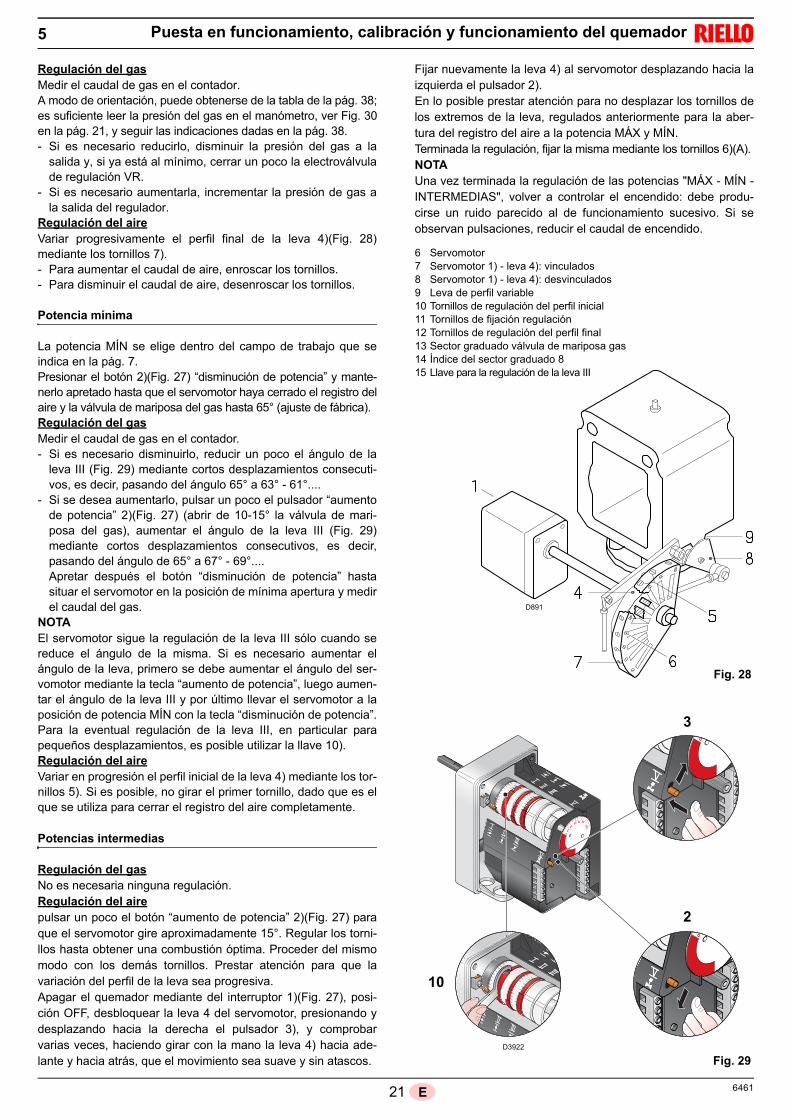
21 6461E
Puesta en funcionamiento, calibración y funcionamiento del quemador5
Regulación del gasMedir el caudal de gas en el contador.A modo de orientación, puede obtenerse de la tabla de la pág. 38;es suficiente leer la presión del gas en el manómetro, ver Fig. 30en la pág. 21, y seguir las indicaciones dadas en la pág. 38.- Si es necesario reducirlo, disminuir la presión del gas a la
salida y, si ya está al mínimo, cerrar un poco la electroválvulade regulación VR.
- Si es necesario aumentarla, incrementar la presión de gas ala salida del regulador.
Regulación del aireVariar progresivamente el perfil final de la leva 4)(Fig. 28)mediante los tornillos 7).- Para aumentar el caudal de aire, enroscar los tornillos.- Para disminuir el caudal de aire, desenroscar los tornillos.
Potencia mínima
La potencia MÍN se elige dentro del campo de trabajo que seindica en la pág. 7.Presionar el botón 2)(Fig. 27) “disminución de potencia” y mante-nerlo apretado hasta que el servomotor haya cerrado el registro delaire y la válvula de mariposa del gas hasta 65° (ajuste de fábrica).Regulación del gasMedir el caudal de gas en el contador.- Si es necesario disminuirlo, reducir un poco el ángulo de la
leva III (Fig. 29) mediante cortos desplazamientos consecuti-vos, es decir, pasando del ángulo 65° a 63° - 61°....
- Si se desea aumentarlo, pulsar un poco el pulsador “aumentode potencia” 2)(Fig. 27) (abrir de 10-15° la válvula de mari-posa del gas), aumentar el ángulo de la leva III (Fig. 29)mediante cortos desplazamientos consecutivos, es decir,pasando del ángulo de 65° a 67° - 69°....Apretar después el botón “disminución de potencia” hastasituar el servomotor en la posición de mínima apertura y medirel caudal del gas.
NOTAEl servomotor sigue la regulación de la leva III sólo cuando sereduce el ángulo de la misma. Si es necesario aumentar elángulo de la leva, primero se debe aumentar el ángulo del ser-vomotor mediante la tecla “aumento de potencia”, luego aumen-tar el ángulo de la leva III y por último llevar el servomotor a laposición de potencia MÍN con la tecla “disminución de potencia”.Para la eventual regulación de la leva III, en particular parapequeños desplazamientos, es posible utilizar la llave 10).Regulación del aireVariar en progresión el perfil inicial de la leva 4) mediante los tor-nillos 5). Si es posible, no girar el primer tornillo, dado que es elque se utiliza para cerrar el registro del aire completamente.
Potencias intermedias
Regulación del gasNo es necesaria ninguna regulación.Regulación del airepulsar un poco el botón “aumento de potencia” 2)(Fig. 27) paraque el servomotor gire aproximadamente 15°. Regular los torni-llos hasta obtener una combustión óptima. Proceder del mismomodo con los demás tornillos. Prestar atención para que lavariación del perfil de la leva sea progresiva.Apagar el quemador mediante del interruptor 1)(Fig. 27), posi-ción OFF, desbloquear la leva 4 del servomotor, presionando ydesplazando hacia la derecha el pulsador 3), y comprobarvarias veces, haciendo girar con la mano la leva 4) hacia ade-lante y hacia atrás, que el movimiento sea suave y sin atascos.
Fijar nuevamente la leva 4) al servomotor desplazando hacia laizquierda el pulsador 2).En lo posible prestar atención para no desplazar los tornillos delos extremos de la leva, regulados anteriormente para la aber-tura del registro del aire a la potencia MÁX y MÍN.Terminada la regulación, fijar la misma mediante los tornillos 6)(A).NOTAUna vez terminada la regulación de las potencias "MÁX - MÍN -INTERMEDIAS", volver a controlar el encendido: debe produ-cirse un ruido parecido al de funcionamiento sucesivo. Si seobservan pulsaciones, reducir el caudal de encendido.
D891
6 Servomotor7 Servomotor 1) - leva 4): vinculados8 Servomotor 1) - leva 4): desvinculados9 Leva de perfil variable10 Tornillos de regulación del perfil inicial11 Tornillos de fijación regulación12 Tornillos de regulación del perfil final13 Sector graduado válvula de mariposa gas14 Índice del sector graduado 815 Llave para la regulación de la leva III
D3922
10
2
3
Fig. 28
Fig. 29

226461 E
Puesta en funcionamiento, calibración y funcionamiento del quemador5
Presostato aire
Regular el presostato aire, después de haber efectuado todaslas demás regulaciones del quemador, con el presostato aireajustado al inicio de la escala (Fig. 30).Con el quemador funcionando a la potencia MÍN, introduzca enla chimenea un analizador de la combustión, cierre lentamentela boca de aspiración del ventilador (por ejemplo con un car-tón) hasta que el valor de CO no supere los 100 ppm. Después gire lentamente la maneta en el sentido de las agu-jas de reloj hasta que el quemador se bloquee. A continuación, controle que la flecha indique hacia arriba en laescala graduada. Girar nuevamente el botón en el sentido delas agujas del reloj hasta hacer coincidir el valor indicado en laescala graduada con la flecha indicando hacia abajo, se recu-pera así la histéresis del presostato representada por el campoblanco sobre fondo azul comprendido entre las dos flechas.Controle ahora el correcto arranque del quemador. Si el quemador se bloquea de nuevo, girar el botón un pocomás, en sentido contrario a las agujas del reloj. Durante estas operaciones puede ser útil utilizar un manóme-tro para medir la presión del aire. La conexión del manómetro se muestra en la Fig. 30.La configuración estándar es la del presostato aire conectadoen forma absoluta. Nótese la presencia de una conexión en“T” no suministrada. En algunas aplicaciones con fuertedepresión la conexión del presostato no permite al mismo laconmutación. En dicho caso es necesario conectar el presos-tato en modo diferencial, aplicando un segundo tubo entre elpresostato aire y la boca de aspiración del ventilador. En estecaso también el manómetro se debe conectar en forma dife-rencial, como se muestra en la Fig. 30.
Presostato gas de máxima
Realice la regulación del presostato gas de máxima despuésde haber efectuado todas las demás regulaciones del quema-dor, con el presostato regulado al final de la escala (Fig. 31).Con el quemador funcionando a la potencia MÁX, disminuyala presión de regulación girando lentamente (en sentido con-trario a las agujas del reloj) el botón que se facilita a talefecto, hasta que se bloquee el quemador.A continuación, girar dicho botón (en el sentido de las agujasdel reloj) 2 mbar y repetir el arranque del quemador.Si el quemador se para de nuevo, girar el botón (en el sentidode las agujas del reloj) 1 mbar.
Presostato gas de mínima
Regular el presostato gas de mínima después de haber efec-tuado todas las demás regulaciones del quemador con el pre-sostato regulado en el inicio de la escala (Fig. 32).Con el quemador funcionando a la potencia MÁX, aumentarla presión de regulación girando lentamente en el sentido delas agujas del reloj el botón que se facilita a tal efecto, hastaque se pare el quemador.A continuación, girar dicho botón (en sentido contrario a las agu-jas del reloj) 2 mbar y repetir el arranque del quemador paraverificar la regularidad de funcionamiento.Si el quemador se para de nuevo, girar el botón (en sentidocontrario a las agujas del reloj) 1 mbar.
+_
+_
Conexión del manómetro con el presostato en forma diferencial
D3951
Conexión del manómetro con el presostato en forma absoluta
D8695
Fig. 30
Fig. 31
D3856
D3855
Fig. 32

23 6461E
5.6 Secuencia de funcionamiento del quemador
Arranque del quemador
• 0s: Cierre TL.• 5s: Arranca el programa de la caja de control eléctrica. El
servomotor arranca: gira 130° hacia la derecha, esdecir, hasta la intervención del contacto en la leva(Fig. 7).
• 35s: El registro de aire llega a la posición de potencia MÁX.Arranque motor ventilador.Comienza la fase de preventilación.
• 75s: El servomotor gira hacia la izquierda hasta el ánguloconfigurado en la leva III (Fig. 7) para la MÍN potencia.
• 95s: El registro de aire y la mariposa del gas se sitúanen la potencia MÍN (con leva III, Fig. 7 a 65°).
• 105s: Se genera chispa en el electrodo de encendido.Se abren las electroválvulas de seguridad VS y deregulación VR, apertura rápida. Se enciende la llama,con poca potencia, punto A.Sigue un progresivo aumento de la potencia, aber-tura lenta de la electroválvula VR, hasta la potenciaMÍN, punto B.
• 108s: Cesa la chispa.• 115s: Termina el ciclo de arranque.
ENCENDIDO NORMAL
Funcionamiento a régimen
Quemador sin el kit para funcionamiento modulanteUna vez terminado el ciclo de arranque, el mando del servomo-tor pasa al TR que controla la presión o la temperatura en la cal-dera, punto C.(De todas formas, la caja de control eléctrica sigue controlandola presencia de la llama y la correcta posición de los presostatosde aire y gas de máxima).• Si la temperatura o la presión es baja y en consecuencia el
TR está cerrado, el quemador aumenta progresivamente lapotencia hasta el valor MÁX (segmento C-D).
• Si luego la temperatura o la presión aumenta hasta la aberturadel termostato TR, el quemador reduce progresivamente lapotencia hasta el valor MÍN (segmento E-F). Y así sucesiva-mente.
• La parada del quemador se produce cuando la solicitud decalor es inferior a la generada por el quemador a la potenciaMÍN segmento G-H. El TL se abre, el servomotor vuelve alángulo 0°. El registro se cierra completamente para reducir laspérdidas de calor al mínimo.
Quemador con el kit para funcionamiento modulanteVer el manual de Instrucciones que acompaña al regulador.
Falta de encendido
Si el quemador no se enciende bloquea en 3 s la alimentacióneléctrica de la válvula gas.Puede ser que el gas no llegue al cabezal de combustión dentrodel tiempo de seguridad de 3 s. En tal caso, aumentar el caudal de gas en el encendido.La llegada del gas al manguito se evidencia en el manómetrode la Fig. 36.
5.7 Apagado del quemador en funcionamiento
Si la llama se apaga durante el funcionamiento, el quemador sebloquea en 1 segundo.
5.8 Parada del quemador
La parada del quemador puede realizarse: interviniendo con el seccionador de la línea de alimentación
eléctrica situado en el cuadro de la caldera; retirando la tapa y accionando el interruptor “AUT/MAN” de
Fig. 27.
MAX
MI N
105
105
95
7535
B
950
0
MI N
MAX
5
115
108
0 sec
M
M
A
115
135
C
D E
F G
H
D3815
Fig. 33
En caso de parada del quemador, para evitardaños en la instalación, no desbloquear el que-mador más de dos veces seguidas. Si el que-mador se bloquea por tercera vez, contactar conel servicio de asistencia. Si se produjeran otros
bloqueos o anomalías en el quemador, las intervencionesdeben ser realizadas únicamente por personal habilitado yautorizado, de acuerdo a lo indicado en este manual y enconformidad con las normas y disposiciones de ley vigen-tes.
0 sec
0
MI N
MAX
5
105 108
M
M
35 75
95
108
108105
108
108
D3816
Fig. 34
ATENCIÓN
Puesta en funcionamiento, calibración y funcionamiento del quemador5

246461 E
Puesta en funcionamiento, calibración y funcionamiento del quemador5
5.9 Medición de la corriente de ionización
El quemador está dotado de un sistema de ionización paracontrolar la presencia de la llama. La corriente mínima para elfuncionamiento de la caja de control es de 6 µA. El quemador genera una corriente netamente superior, noprecisando normalmente ningún control. Si, de todas formas, se quisiera medir la corriente de ionizaciónhay que desconectar la clavija-toma (2)(Fig. 35) colocada en elcable de la sonda de ionización e introducir un microamperíme-tro (1)(Fig. 35) para corriente continua de 100 µA final de laescala. ¡Atención a la polaridad!
5.10 Control de la presión del aire y del gas en el cabezal de combustión
5.11 Controles finales (con el quemador funcionando)
Abrir el termostato/presostato TL: Abrir el termostato/presostato TS:el quemador debe pararse Girar el botón del presostato gas de máxima hasta la posi-
ción de final de escala mínimo. Girar el botón del presostato aire hasta la posición de final
de escala máximo.el quemador debe bloquearse Apagar el quemador y cortar la tensión. Desconectar el conector del presostato gas de mínima.el quemador no debe arrancar Desconectar el cable de la sonda de ionización.el quemador debe bloquearse por falta de encendido Comprobar que los bloqueos mecánicos de los dispositivos
de regulación estén bien apretados.
2
1
Fig. 35
D8696
+_
+_
Fig. 36
Presión aire
Presión gas
D8697

25 6461E
La caja de control tiene su propia función diagnóstica mediante la cual es posible detectar fácilmente las posibles causas de malfuncionamiento (señalización: LED ROJO).Para utilizar tal función, hay que esperar al menos 10 segundos desde el instante de bloqueo de la caja de control y presionar elpulsador de desbloqueo durante un tiempo mínimo de 3 segundos.Después de haber soltado el botón, el LED ROJO comenzará a parpadear, como ilustra la siguiente imagen.
Los impulsos del LED aparecen con intervalos de aproximadamente 3 segundos.La cantidad de impulsos dará la información sobre las posibles averías según la siguiente tabla.
SEÑAL ANOMALÍA CAUSA PROBABLE SOLUCIÓN
2 parpadeos Superado el pre-ven-tilación y el tiempo de seguridad, el quema-dor se bloquea sin aparecer la llama
1 - La electroválvula de funcionamiento deja pasar . . . . Aumentarlopoco gas
2 - Una de las dos electroválvulas no se abre. . . . . . . . . Sustituirlas3 - Presión gas demasiado baja . . . . . . . . . . . . . . . . . . . Aumentarla en el regulador4 - Electrodo de encendido mal regulado . . . . . . . . . . . . Regularlo, véase Fig. 125 - Electrodo a masa para aislante roto. . . . . . . . . . . . . . Sustituirlo6 - Cable de alta tensión defectuoso . . . . . . . . . . . . . . . . Sustituirlo7 - Cable de alta tensión deformado por . . . . . . . . . . . . Sustituirlo y protegerlo
la alta temperatura 8 - Transformador de encendido defectuoso . . . . . . . . . Sustituirlo9 - Conexionado eléctrico válvulas o transformador . . . Rehacer las conexiones
de encendido incorrecto 10 - Caja de control defectuosa. . . . . . . . . . . . . . . . . . . . . Sustituirla11 - Una válvula antes de la rampa de gas, cerrada. . . . . Abrirla12 - Aire en las tuberías . . . . . . . . . . . . . . . . . . . . . . . . . . Purgarlo13 - Válvulas de gas no conectadas o . . . . . . . . . . . . . . . Verificar el conexionado o sustituir bobina
con bobina interrumpida
3 parpadeos El quemador no arranca y aparece el bloqueo
14 - Presostato aire en posición de funcionamiento . . . . . Regularlo o sustituirlo
El quemador arranca y luego se bloquea
El presostato aire no conmuta por presión aire insuficiente:15 - Presostato aire mal regulado . . . . . . . . . . . . . . . . . . . Regularlo o sustituirlo16 - Tubo toma presión del presostato obstruido . . . . . . . Limpiarlo17 - Cabezal mal regulado . . . . . . . . . . . . . . . . . . . . . . . . Regularlo18 - Alta presión en cámara combustión . . . . . . . . . . . . . . Conectar presostato aire a la aspir. ventil
Bloqueo durante la pre-ventilación
19 - Contactor mando motor defectuoso . . . . . . . . . . . . . . Sustituirlo(sólo versión trifásica)
20 - Motor eléctrico defectuoso . . . . . . . . . . . . . . . . . . . . . Sustituirlo21 - Bloqueo motor (sólo versión trifásica) . . . . . . . . . . . . Sustituirlo
4 parpadeos El quemador arranca y luego se bloquea
22 - Simulación de llama . . . . . . . . . . . . . . . . . . . . . . . . . Sustituir la caja de control
Bloqueo al pararse el quemador
23 - Permanencia de la llama en el cabezal de. . . . . . . . . Eliminar permanencia de llama o combustión o simulación de llama sustituir la caja de control
6 parpadeos El quemador arranca y luego se bloquea
24 - Servomotor defectuoso o mal regulado . . . . . . . . . . Sustituirlo o regularlo
7 parpadeos El quemador se bloquea al aparecer la llama
25 - La electroválvula de funcionamiento . . . . . . . . . . . . . Aumentarlo deja pasar poco gas
26 - Sonda de ionización mal regulada . . . . . . . . . . . . . . . Regularla, véase Fig. 1227 - Ionización insuficiente (inferior a 5 µA) . . . . . . . . . . . Controlar posición sonda28 - Sonda a masa . . . . . . . . . . . . . . . . . . . . . . . . . . . . . . Separarla o sustituir cable29 - Insuficiente puesta a tierra del quemador . . . . . . . . . Revisar la puesta a tierra30 - Fase y neutro invertidos . . . . . . . . . . . . . . . . . . . . . . . Invertir31 - Avería del circuito de detección llama . . . . . . . . . . . . Sustituir caja de control
Bloqueo del quema-dor en el paso entre potencia mínima y máxima y viceversa
32 - Demasiado aire o poco gas . . . . . . . . . . . . . . . . . . . . Regular el aire y el gas
En funcionamiento, el quemador se bloquea
33 - Sonda o cable ionización a masa. . . . . . . . . . . . . . . . Sustituir la(s) pieza(s) deteriorada(s)
10 parpadeos El quemador no arranca y aparece el bloqueo
34 - Conexiones eléctricas incorrectas . . . . . . . . . . . . . . . Comprobarlas
3sSeñal SeñalLED ROJO encendido
presione el desbloqueo durante 10sIntervaloPresionar el pulsador
por > 3s
Anomalías - Causas - Soluciones6

266461 E
6.1 Funcionamiento normal / tiempo de detección llama
La caja de control tiene una función ulterior mediante la que es posible asegurarse del correcto funcionamiento del quemador(señal: LED VERDE permanentemente encendido).Para utilizar tal función, hay que esperar al menos 10 segundos desde el instante de encendido del quemador y presionar el pul-sador de la caja de control durante un tiempo mínimo de 3 segundos.Después de haber soltado el botón, el LED VERDE comenzará a parpadear, como ilustra la siguiente imagen.
Los impulsos del LED aparecen con intervalos de aproximadamente 3 segundos.El número de impulsos determinará el TIEMPO DE DETECCIÓN de la sonda desde la apertura de las válvulas gas, según lasiguiente tabla.
El quemador se bloquea
35 - Caja de control defectuosa. . . . . . . . . . . . . . . . . . . . . Sustituirla36 - Presencia de perturbaciones electromagnéticas . . . . Filtrarlas o eliminarlas
en las líneas termostato 37 - Presencia de perturbaciones electromagnéticas . . . . Utilizar el kit protección contra las interfe-
rencias radio
Ningún parpadeo El quemador no arranca
38 - Falta tensión eléctrica . . . . . . . . . . . . . . . . . . . . . . . . Cerrar interruptores; comprobar conexiones39 - Un telemando de límite o de seguridad abierto . . . . . Regularlo o sustituirlo40 - Fusible de linea fundido . . . . . . . . . . . . . . . . . . . . . . . Sustituirlo41 - Caja de control defectuosa. . . . . . . . . . . . . . . . . . . . . Sustituirla42 - Falta de gas . . . . . . . . . . . . . . . . . . . . . . . . . . . . . . . . Abrir válvulas manuales entre contador y
rampa43 - Presión gas en red insuficiente . . . . . . . . . . . . . . . . . Contacte con la COMPAÑÍA DE GAS44 - El presostato gas de mínima no cierra . . . . . . . . . . . . Regularlo o sustituirlo45 - Servomotor no va a la posición de mín. encendido . . Sustituirlo
El quemador repite el ciclo de arranque sin bloquearse
46 - La presión de gas en la red está cercana al valor . . . Reducir la presión de intervención del presostato gas de mínima al que está regulado . presostato gas de mínimael presostato gas de mín Sustituir el cartucho del filtro gasLa caída de presión repentina que sigue a la aperturade la válvula provoca la apertura temporal delpropio presostato, inmediatamente la válvula se cierray se detiene el quemador. La presión vuelve a aumentar, el presostato se cierray hace que el ciclo de arranque vuelva a comenzar Y así sucesivamente.
Encendidos con pul-saciones
47 - Cabezal mal regulado . . . . . . . . . . . . . . . . . . . . . . . . Regularlo; ver Fig. 1548 - Electrodo de encendido mal regulado . . . . . . . . . . . . Regularlo, véase Fig. 1249 - Registro ventilador mal regulado; demasiado aire . . . Regularlo50 - Potencia de encendido demasiado elevada. . . . . . . . Reducirla
El quemador no alcanza la potencia máxima
51 - Telemando TR no cierra . . . . . . . . . . . . . . . . . . . . . . . Regularlo o sustituirlo52 - Caja de control defectuosa. . . . . . . . . . . . . . . . . . . . . Sustituirla53 - Servomotor defectuoso . . . . . . . . . . . . . . . . . . . . . . . Sustituirlo
El quemador se detiene con el registro vent. abierto
54 - Servomotor defectuoso . . . . . . . . . . . . . . . . . . . . . . . Sustituirlo
SEÑAL TIEMPO DE DETECCIÓN LLAMA A cada arranque del quemador, se actualiza este dato.Una vez realizada la lectura, apretando brevemente elpulsador de la caja de control, el quemador repite el ciclode arranque.
ATENCIÓNSi resulta un tiempo > 2 s se tiene el encendido retra-sado.Controle la regulación del freno hidráulico en la válvulagas y la regulación registro de aire y cabezal de combus-tión.
1 parpadeo0,4 s
2 parpadeos0,8 s
6 parpadeos2,8 s
SEÑAL ANOMALÍA CAUSA PROBABLE SOLUCIÓN
3sSeñal SeñalLED VERDE encendido
presione el desbloqueo durante 10sIntervaloPresionar el pulsador
por > 3s
Anomalías - Causas - Soluciones6

27 6461E
Mantenimiento
7.1 Notas sobre la seguridad para el mantenimiento
El mantenimiento periódico es fundamental para el buenfuncionamiento, la seguridad, el rendimiento y la duración delquemador.El mismo permite reducir los consumos, las emisionescontaminantes y mantener el producto confiable a través deltiempo.
Las intervenciones de mantenimiento y la calibra-ción del quemador deben ser realizadas por perso-nal habilitado y autorizado según todo lo indicadoen el presente manual y en conformidad con lasnormas y disposiciones de ley vigentes.
Antes de realizar cualquier operación de mantenimiento, lim-pieza o control:
cortar la alimentación eléctrica del quemador con elinterruptor general de la instalación;
cerrar la válvula de interceptación del combustible;
PELIGRO
PELIGRO
PELIGRO
7
7.2 Programa de mantenimiento
La instalación de combustión de gas debe ser controladaspor lo menos una vez al año por un encargado de laempresa fabricante o por otro técnico especializado.
CombustiónEfectuar el análisis de los gases de combustión que salen dela caldera. Las diferencias significativas respecto al últimoanálisis indicarán los puntos donde deberán centrarse lasoperaciones de mantenimiento.
Fugas de gasComprobar que no haya fugas de gas en el conducto conta-dor-quemador.
Filtro de gasSustituir el cartucho filtrante cuando esté sucio.
Visor llamaLimpiar el cristal del visor de la llama, (Fig. 37).
Cabezal de combustiónAbrir el quemador y verificar que todas las partes del cabezalde combustión estén:- completas;- no deformadas por la alta temperatura;- sin impurezas provenientes del ambiente;- sin corrosión de los materiales componentes;- correctamente posicionadas. Asegurarse de que los orificios de salida del gas para la fasede encendido en el distribuidor del cabezal de combustión, nopresenten impurezas o depósitos de herrumbre.En caso de dudas, desmontar el codo 5)(Fig. 38).
ServomotorDesbloquear la leva 4)(Fig. 28) del servomotor, presionandoy desplazando el pulsador 3)(Fig. 29), hacia la derecha y con-trolar manualmente que su rotación, hacia adelante y atrás,se efectúe con facilidad. Vincular nuevamente la leva despla-zando hacia la izquierda el pulsador 2)(Fig. 28).
QuemadorVerificar que no haya un desgaste anormal o tornillos flojosen los mecanismos que controlan el registro del aire y la vál-vula de mariposa del gas. Igualmente, los tornillos que fijanlos cables eléctricos en la regleta del quemador deben estarbien apretados.Limpiar exteriormente el quemador, en particular las rótulas yla leva 4)(Fig. 28).
CombustiónRegular el quemador si los valores de la combustión obteni-dos al inicio de la intervención no cumplen las normas envigor o no corresponden a una buena combustión.Anotar en una ficha de control los nuevos valores de la com-bustión; serán útiles para controles sucesivos.
Frecuencia del mantenimiento
Control y limpieza
D709Fig. 37

286461 E
7.3 Apertura del quemador
Cortar la alimentación eléctrica del quemador. Aflojar los tornillos 1) y sacar la tapa 2). Soltar la rótula 7) del sector graduado 8). Montar los dos alargadores en las guías 4). Quitar los tornillos 3) y hacer retroceder el quemador unos
100 mm sobre las guías 4). Desconectar los cables de lasonda y del electrodo y desplazar todo el quemador.
En este punto es posible extraer el distribuidor de gas 5),después de haber desenroscado el tornillo 6).
7.4 Cierre del quemador
Empujar el quemador hasta aproximadamente 100 mmdel manguito.
Volver a conectar los cables y hacer desplazar el quema-dor hasta el tope.
Volver a colocar los tornillos 3) y tirar suavemente haciaafuera los cables de sonda y electrodo, hasta tensarlosligeramente.
Volver a enganchar la rótula 7) en el sector graduado 8). Desmontar los dos alargadores de las guías 4).
2
4
6
5
1
8
7
1
3
D8698
Fig. 38
Mantenimiento7
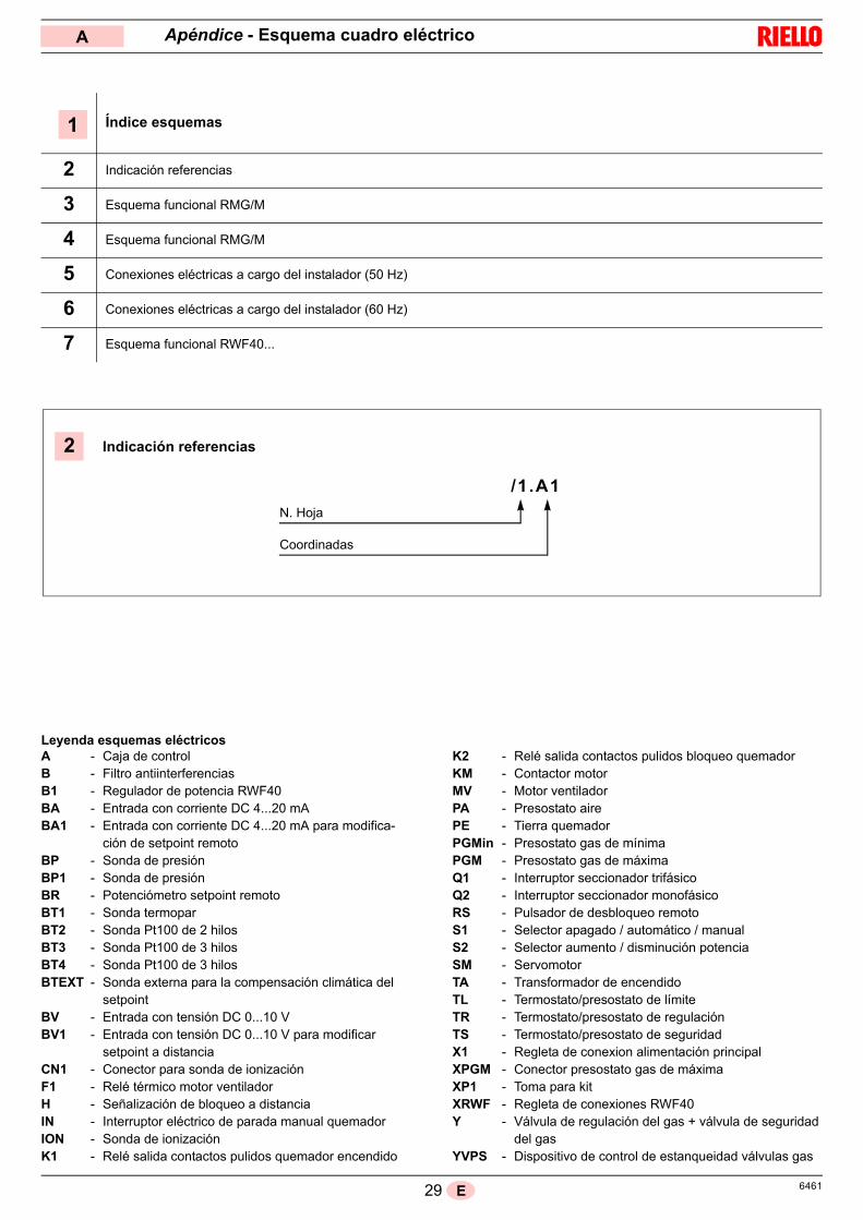
29 6461E
Índice esquemas
2 Indicación referencias
3 Esquema funcional RMG/M
4 Esquema funcional RMG/M
5 Conexiones eléctricas a cargo del instalador (50 Hz)
6 Conexiones eléctricas a cargo del instalador (60 Hz)
7 Esquema funcional RWF40...
1
2
N. Hoja
/1.A1
Coordinadas
Indicación referencias
Apéndice - Esquema cuadro eléctricoA
Leyenda esquemas eléctricosA - Caja de controlB - Filtro antiinterferenciasB1 - Regulador de potencia RWF40BA - Entrada con corriente DC 4...20 mABA1 - Entrada con corriente DC 4...20 mA para modifica-
ción de setpoint remotoBP - Sonda de presiónBP1 - Sonda de presiónBR - Potenciómetro setpoint remotoBT1 - Sonda termoparBT2 - Sonda Pt100 de 2 hilosBT3 - Sonda Pt100 de 3 hilosBT4 - Sonda Pt100 de 3 hilosBTEXT - Sonda externa para la compensación climática del
setpointBV - Entrada con tensión DC 0...10 VBV1 - Entrada con tensión DC 0...10 V para modificar
setpoint a distanciaCN1 - Conector para sonda de ionizaciónF1 - Relé térmico motor ventiladorH - Señalización de bloqueo a distanciaIN - Interruptor eléctrico de parada manual quemadorION - Sonda de ionizaciónK1 - Relé salida contactos pulidos quemador encendido
K2 - Relé salida contactos pulidos bloqueo quemadorKM - Contactor motorMV - Motor ventiladorPA - Presostato airePE - Tierra quemadorPGMin - Presostato gas de mínimaPGM - Presostato gas de máximaQ1 - Interruptor seccionador trifásicoQ2 - Interruptor seccionador monofásicoRS - Pulsador de desbloqueo remotoS1 - Selector apagado / automático / manualS2 - Selector aumento / disminución potenciaSM - ServomotorTA - Transformador de encendidoTL - Termostato/presostato de límiteTR - Termostato/presostato de regulaciónTS - Termostato/presostato de seguridadX1 - Regleta de conexion alimentación principalXPGM - Conector presostato gas de máximaXP1 - Toma para kitXRWF - Regleta de conexiones RWF40Y - Válvula de regulación del gas + válvula de seguridad
del gasYVPS - Dispositivo de control de estanqueidad válvulas gas

306461 E
Apéndice - Esquema cuadro eléctricoA
���������
�
� ��
�����������
�
��
�
�
��
�
�� �
�
��
��
��
��
��
�
�
�
��!�"��#$%&'$�(�
����)�����(��
�$'"�*+%��(�
�'����)�'���(�
��
,�� �-�
.��
��
��
�
��
�� ��
�� �
�
��
��
��
�/
(�
0�
��
�/
(�
0�
. , 1 � �
. , 1 � �
�,�� ��2�3�-����� ��
�
�� ����-���
��-����4-2�
.�����.��,�� �� ��
���
�,�� ��-�,��-������ ��
�/���/��
��
��5� (6�
��
�� /7��(889�� :..
�;�6� ��
� /
( �
�/�.��/�./
<0 <�
<( <�
�/�./
��
(
�/
�
��� ����� ��
����
����
:.,
:.,
�
��%�:.
,
:.,
�
:.,
/�+
=$*�'$>?
��
�
��� ����
�5�(
����
��
��
�
� �
.
./��
���/
��
��
��
��
( �
�
,��/ ��
��
,0�/ ��
���
��
�@
/ ��
��
:.,
,
�-�,
��
�
�+�A
�
�+�A�/
:
�
�+�A
�0
./��
���/
�
�
�/�.�
��
���/
�
/
/�/��
��/�,�
�.�/�,�
�/�,�
��/�,�
,�/�,�
.2�B�.�2���.�2����.��2���.�2
.��B����-���.�,�����-������,���3
4��B�����-���4���-����C2��������.
���B����1���������������������D�
�1�B��-��-�����1����-2������-�
���B�.��,-����
�������.��,����
����
-�B��
�,�-���-�
������-�
������-�
���
��B���-����-�����-��������-��������-����
�4B������-������4������������
2��B��-�
�����������-������-�
�1B�-�-����-�1���-�����-�1
� B��2�,��������2� 2-�������2� 2-�������2����.�2
��B������-�����������������������.��
��4�B�����-�
���1����4���-����������C2�������������.�
��2�
.��B� ��-�����.�-����� ��-����.�
2�
��
2���
2���
��
:..
����
�-1
2�-
�5
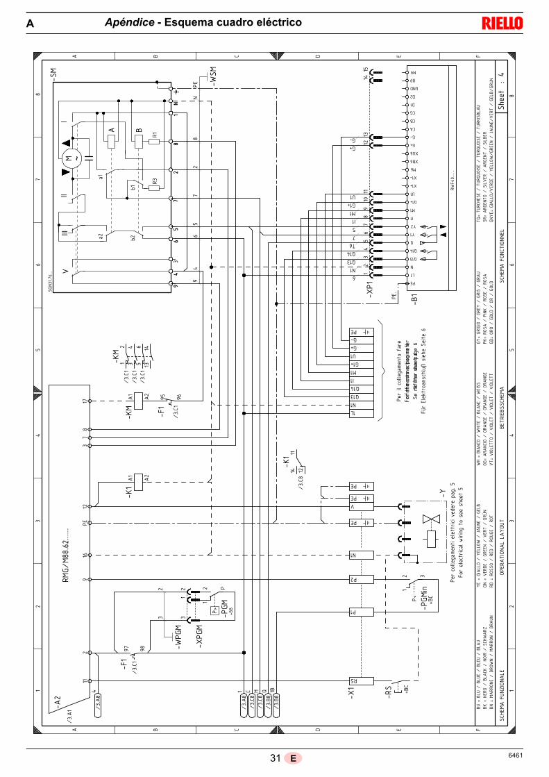
31 6461E
Apéndice - Esquema cuadro eléctricoA
���
������
�
�� �
�����������
���
���
�� �
��
��
���
���
�
�� �
���
�
���
���
���
���
���
���
��
�����
�
�
����
���
����
�
��
��
�
�
��
��
�
� ! " # �
� ! " # �
�!$#
���%&
'�(&
)#
(�#�
*�(&
)�)
�(%
*�#
*��#��
�!$#
�
�!$#
���(&
!*�(&&
#)
����
�����
�����!
���!�
$���!�
+�����
�������
��
��
,�!
��- ,�!
�
��.�/011�
234��
����1���.�/��5�6
�.��73
2���
�0.��1�/�.�/31�8
�.��2��0�9��
�9��
����
���!�
: :�
�� �
��;
�
��
�
�
: �
��
&�
�#
�#
�
��#
�#
�
���!�
�� ���
�
�
��.��1�/011�
234��
�0�<3.�
.�<�.�4��
�0�3�732
��3��
�0.�����/0��
�/��0�
�.�<�.
�0����
�9��
����
���.=<=.�.�3>?
�732
���
�@.�#1�A
�.03
�9/�1>B�
9���
����
�����
�)&��
�
���!�
���!�
���!�
� � � ��
� � ��
���!�
:� :�
+��+������ �,%� , ��#
�#�
:
����
C�C
3�3
:�
��
�
�
�&
:�
�� ��
�� &��
+��� �
+��� �
*�� ��
�� � �
�
�� ��
��� �
��� :
�,� �D
� %�� ��
�
,� ��
�� �� ��
�&
&��#
� ����
E
�%�F��)%
����)%
#����)#%����)
%��
�F�&#�
(����)
!���
�&(������!$
��'
�#�F� �))(����
#))(
���
�G%&
#��� #)�
&�F��
#�"#
��� �#
#&��
��#�
*��� �H
&�"
�F��(�
�(��
��#"
����(%
#��
��(*
�$�F���&!
(����
$�*#
����)
&!��
��#���
( F��
&!�(��
�(�
& #���(�
& #���(�
& #
�*F
���()#**
(����
�()#*����
�()#*����
�()#**
�F� �
� �(��
� �#
���
� ������ �
%��
F��(
���
���&�����(�
#����(�
"
F�(�
(��� ()
"���(���� ()
"
*+F�*%
�!$#
�#��
�*%�
+%(
��#���*%�
+%(
��#���*%�
����
)%
��F��
#&*(
�����)�#�
���
� #&
*�����)�#
� &
�#F� �))(�
�#�
"#��
��#))(
�� �
##&���G%&
#��#�
*��� #)��
�%&
�&�F��
��
(&#�����(
�&����
��
(&��
���
%&
,��
�+&�
�� ����
�#
)�
&
+��
+��
+
��
�
��
��
�,
%�
��,
���
��
���
�%�
,
�
!
!�
!
"�
"
&"
�:
�:
����
D������
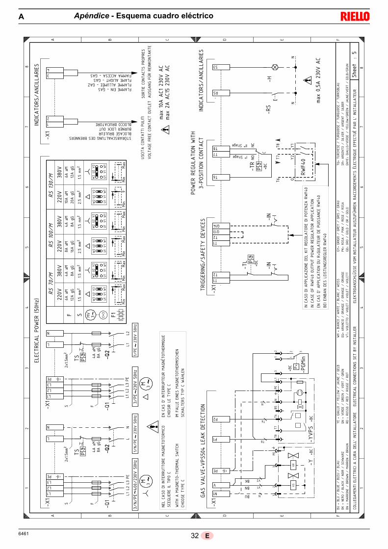
326461 E
Apéndice - Esquema cuadro eléctricoA
���
������
�
��
�
�� �
����
���
��
�
�
�������
�����
�����������
����
���
� ��
�� ��
�
��
�
�� ��
�� ��
�����!
�������
"�!
�#��$%
&�
' �
!��(�)
�!�
���)�
��
*+��
'
��
*+��
��
*+��
!��*�)�
�
����
�
���
�!� �
!��
)��
'���
����
����
���
!"'�
�
��"�!
�!�
,������
�"��$
*���
������
����
����
��! �
�
�
�!�
������
��!�
)���
����
!���
-
./0���
���� *����
�./0� ���
��� *��
���
������
��!�
)���
����
!���
./0��1��� *����
�
�$
*�
�2
(+
*�
�2
(+
� 3 � � � '
� 3 � � � '
����
� ����
������
��!�����
��,!
���
���4����
����
���
!���
���!
�������
����
����
����
��3�
����
����
�!��
���!
����
�$�5
�������
����
����
���
,!��
,�6,
'5$!
��!�
���!
�����
���7��
��!��,
���'
'���
,7��
�!�
�4����
����
���
,!
������
����
������
!!,�
��!�
��� �
����
�!����
���
���!
������
����
�
"��$�
���
� �
����
�$�!
�����"
���$
�$��
����
���
��
� '
�
�
�3,
3�
�8
�3�
�3�
�3�
3�
�
�
�
*)�)
������
�) *��
���$
%
*
�*
�*
��
��
��
)�)
����� *�
����$
%
���/�
+��9
0-�
..:
�� �� �
� �������
�4����
�!!,
���,
!��� �
7���
$�!�
��,�
�$����!�
����
���
��
���'���
������
���� �
����
$�!�
���$
����
$���
�!��
����
��";$�
��
� '
�
�
�
�
�*)��
�� *��
���$
%
*
�*
�*
��
��
���/�
+��9
0-�
..:
�
�
)��
��� *�
����$
%
�
�
2��/�
��9
-��.
.:
-��.
.:
��
*
���/�
+��9
+��/�
2��9
-��..:
-��.
.:
���/�
+��9
���/�
���9
-��..:
-��.
.:
2��/�
��9
���
�/0
���
�/0
���
<���
�/0
���
�/0
���
�/0
�������
�������
����
6���
����
������
!� �
����
!���
����
���6
��!
"'�
�
�������
��'�!"
'����,
��,�
���"
�!�!
� ,�
���
!����
����
����
�������
�4��
������
����
��,�
!� ,
����
,!��
���,
����
����!"
'��
3������3
���
����
�����,
� �!
� ��
!�!"
'��
�
-
�
�3�
�� �*��
�2
�
�+�2 �
�
�(,�����
����
����
���,
����
���
�� �
�'!�
����
�����
��,�
���
�=���/9��( �
����
�3�
�+��=���/9�
��>!�3��$���,� �����3!����!�3���� ��3!,��,!3,!��!�������,�
3������3!,�����!�
�
��!�
������
����
���!
��!�
�
�,�
��
�'5!
�!����
����
���
!�'������������ ��'���������,�7���� �6'�������� $���� ��
* '��������������� ���
�*
�
??
??
?
3,�@�3�,
�)�3�,
��)�3��,�)�3��
,3�
�@���!
��)�3��
���)
����!�)���$
"�!6
���@� ������)��
����
"�)
�A�,�
��)� ��3
��@��
�!��
�)� !�
���)
���!
��)� !5
�!�
�@�!��
���)
�!��
�)�!�,
��)
�!��
"$�@�3����
��)�"
$���
�)�3��
���)
�"����
� @��!�
�����)
��!�
� ��)��!�
� ��)��!�
� �
��@
��������
��)��
������)��
������)��
������
�@� !
� ���)
� !�
��)
� !���)� !�
,��
@�!�
���)
������)�!��
��)�!��
� �
@��!
��)� ��
��)��!�)� ��
�
��@��,
!�$�
���)
��,!
�,����
�)��,!
�,����
�)��,!
���3
��,
�!@��!
����
�)������!
�)��
! ��
��)����3�
! �
��@� �����)
��!
���)
������
") !
����)�A�,�
�)��!
��)� ��3)
!,�
3��@��
�!!
����)�3!�
"��)��
�!!
���)
�3!�
,�
�+
�2
�
�+�(
�23�
���
�*
*
��
�!
*��
�
�
�
�"
," ,
�
,�"
�
, "
�"
," ,
�
,�"
�
, "
�"
," ,
�
,�"
�
, "
??

33 6461E
Apéndice - Esquema cuadro eléctricoA
���������
�
��
�
�� �
�������
��
�
�
�����������������������������
� ��!
�� ��!
�
��
�
�� ��!
�� ��!
�����"�������#�"�$��%&'
( �
"��)�*�
"����*�
!+��
����
(
!+��
����
!+��
����
"��+�*�
�
����
�
��
�"� �"� *��
(���
��������
��
"#(��
��#�"�"� ,����� �#
��%
+�������� ��� ��
��
��" �
�
�
�"�
� ������"�*� �����"���
-
./0�������!+�����
./0�!������!+�����
� ������"�*� �����"���
./0��1���!+�����
�%
!
+�
��
)2
!
+�
��
)2
� 3 � � � (
� 3 � � � (
����� ��� ��������
"�������,"
������4�� �
�������
"������"
�������
�����
������3�
�� �
�����"
�����"
�� �
�%�5��
�����
�� �
�������,"
��,�
6,(5%"
� "�
���"
���� ��
�7����"��,
���((���,7���"��4�� �
�������,"
�����
������� ��""
,���
"����
����
�"����
��� ���"�����������
#��%�����
�����%
�"�����#
���%
�%��
���������
� (
�
�
3,
3
�8
�3�
�3�
�3�
3�
�!
�!
�
+* *
����+2�*!!�����%&
+
�+
�+
��
��
��
* *
�����!!�����%&
���/�
2��9
!0-�..:
�� �
�!� ������4�� �
�"",
���,"���
7���
%�"�
��,�
�%����"����������
���(������� �����
����
%�"�
���%�
��%�
���"����
����#;%��
� (
�
�
�!
�!
�+*����!!�����%&
+
�+
�+
��
��
���/�
2��9
!0-�..:
�
�
*�����!!�����%&
�!
���/�
!��9
-��..:
-��..:
��
+
���/�
2��9
2��/�
���9
!-��..:
-��..:
���/�
2��9
���/�
!���9
!-��..:
-��..:
���/�
!��9
���
�/0
���
�/0
���
<���
�/0
���
�/0
���
�/0
� �����
�������
����
6��
����������"� �
����
"�������
�� 6
��"#(��
� �������(�"#
(����,
��,�
���#
�"�"� ,����
"����
����
���
� ������4����
����
���
��,�"� ,
����,"
�����,
����
���"#
(��
3����� 3
� ����������,
�"
� ��"�"#
(��
�
-
�!
�3�
��!�+��
��
�!
�2�� �
�
�),�����
���
����
���,
����
�����
��("����� �
�����,�
���
�=���/9��) �
� �
�3�
�2��=���/9�
��>"�3��%���, �����3"� �"�3���� ��3",��,"3," �"�������,�
3������3",�����"�!
��"�
�����
�������"
��"��
�,�
�
�(5"
�"�� �
� ��
���
"�(�������� ��� ��(���������,�7���� �6(�������� %���� ��
+ (��������������� ���
�+
??
??
?
3,�@�3�,�*�3�,��*�3��,�*�3��,
3��@� �"��*�3�����*� ��"�*���%#�"6
���@� ������*������#�*�A�, ��*� ��3
�@���"���*� "�� �*���"��*� "5
"��@�"�����*�"���*�"�, ��*�"��
#%�@�3�� ���*�#
%����*�3�� ��*�#
����
� @��"�
����*��"�
��*��"�
��*��"�
�
��@����������*��������*��������*��������
�@� "� ���*� "���*� "���*� "�
,��@�"���
�*��� ��*�"����*�"���
�@��"��*� ����*��"�*� ���
��@��,"�%����*��,"�,
�����*��,"�,
�����*��,"���3��,
�"@��" � ���*������"�*��" � ��*����3�"
��@� �����*
��"���*������#* "�� �*�A�, �*��"��*� ��3*
",
3 �@���""� ��*�3"�# �*���""� �*�3"�
,
�2
��
�2�)
��3�
��
�+
!
! +
��
�"
!
+��
�!
�
�#
,#!,!
�!
,�#
�!
,!#!
�#
,#!,!
�!
,�#
�!
,!#!
�#
,#!,!
�!
,�#
�!
,!#!
??

346461 E
Apéndice - Esquema cuadro eléctricoA
���������
�
���
���
���
��������
���
�
�
��
�������
�
��
��
���
�
�����
��� !������ ��"�!���"
��
��
�#$�!���"��"�$�� ��%�&�'()��*****
��(
���
�
��
��+
��
��
��, �!
��
���������-����������"�$�
�!
��
���������-����� �#$�!���"��"�$�� ��%�������������
��
�.
��
�.
��
���������-����������"���"�$��!"#�������"���%���
(
+,
/'
�0
(
+,
/'
�0
! � # � �
! � # � �
��%� !��$"1��"!���� �,)***
� �,)***�����!���"!���!-�$�
��������%� !�� �,)***
��%� !���"����""���� �,)***
����
�
�23�����4��3��3�
)5,6���()7!��)5(6��).�#�
" (
��&+ +&, ,
�' /
�� '
�0 �
�!�8#�8#��
� 0
9
:� )
$ ��8#�8#��
������������;������,0/
�::"#
:� (
:� +
:�
��������4������4��;�������<23���
#��(,.�=�+)7!
:�
�
9
� 9
:�
%
"
&�'()��*****
:"
)=).:�
:�
� $
'
�
�
�'
:�
:�
��
(
��
,****()7!
���))
%
%
�#�#
��
��
� �'
)�()7!��,�()7!�#�
�
)�()7!��,�()7!�#�
� '
:�
�$'
)�.��)�).�#�
$
)�.��)�).�#�
:�
� '
�
��
�
��
$�>��$�=��$��=���$�=��!$
?�>�"����=��!�?�=�"����=���% !�1
-��>�:�!����=�-���� �=�@!$"��=�:��
:"�>�.��#��=�:���"�=�.����=�:�A"
�#�>�������=���#�=���$:��=����
%�>��!"���=� %����=��!"��=� ����
�:>�!�!"����=���!":��=���!":��=���!":�
.�>�.��������=�.������=�.������=�.������
:->�:��:���=�:��-�=�:����=�:�!$
�?>����!�=���"?�=������=����!
:#>�����=�:��#�=����=�:��#
�&>��$��%����=��$�&$�����=��$�&$�����=��$�?���!$
��>�!�:�"���=����.���=�!�:�"��=������
:"-�>�:�!���=.��#��=�-���� =:���"�=�@!$"�=.����=�:��=:�$"
"�>� !���"��=��� "�=� !���"�=��!$"
��
� �,)*********
�
"
&+
&
&,
-
-(
�
:�
$
��
��
'
�'
�$'
:�
:�
�!
�
�:
#
#(
:"#
9
9
����7���3���
�3�<�2����7�����3��
��<�<����������7�7����
���(�B��������3��
��<�<�����
��������7����
��<�<����������7�7����
���+�B��������3��
#������B�����3�������3��3�
���C��B�����3�������3��3�
#������B���������4���3��3�
���C��B���������4���3��3�

35 6461E
Kit regulador de potencia para funcionamiento modulante
Con el funcionamiento modulante el quemador adecua constantemente la potencia a la solicitud de calor asegurando gran estabilidaddel parámetro controlado: temperatura o presión. Hay que pedir dos componentes: • el regulador de potencia, que se instala en el quemador; • la sonda que se instala en el generador de calor.
Kit regulador de potencia con señal 4-20 mA, 0-10V
Hay que pedir dos componentes: • el convertidor de señal analógico;• el potenciómetro.
Kit potenciómetro para indicación posición de carga
Kit interfaz adaptador RMG a PC
Caja insonorizador
Kit cabezal largo
Kit para funcionamiento con GPL
Parámetro a controlar Sonda Regulador de potencia
Campo de regulación Tipo Código Tipo CódigoTemperatura - 100...+ 500°C PT 100 3010110
RWF40 3010414Presión
0...2,5 bar0...16 bar
Sonda con salida
4...20 mA
30102133010214
Quemador Potenciómetro Convertidor de señal analógico
RS 70-100/M - RS 130/MTipo Código Tipo Código
ASZ... 3010416 E5202 3010415
Quemador Código Kit
RS 70-100/M - RS 130/M 3010416
Quemador Código Kit
RS 70-100/M - RS 130/M 3002719
Quemador Código Kit Tipo Reducción media ruido
RS 70-100/M - RS 130/M 3010404 C4/5 10 [dB(A)]
Quemador Código KitLongitud cabezal
estándarLongitud cabezal a obtener con el kit
RS 70/M 3010117 250 mm 385 mmRS 100/M 3010118 250 mm 385 mmRS 130/M 3010119 280 mm 415 mm
QuemadorCabezal de combustión
Código KitPotencia que puede obtenerse con el Kit
RS 70/MTC 20008175
200/470 ÷ 930 kWTL 20008176
RS 100/MTC 20008177
300/700 ÷ 1340 kWTL 20008178
RS 130/MTC 20008179
300/920 ÷ 1600 kWTL 20008180
Apéndice - Accesorios (sobre demanda)B

366461 E
Kit para funcionamiento a TOWN GAS - no homologados CE
Kit distanciador
Kit ventilación continua
Kit reducción vibraciones (para calderas de inversión de llama)
Kit protección contra las interferencias radio
En caso de instalar el quemador en ambientes especiales expuestos a interferencias radio (emisión de señales de más de 10 V/m) debidoa la presencia de INVERTER o en aplicaciones donde las conexiones del termostato superan los 20 metros de longitud, se encuentradisponible un kit de protección como interfaz entre la caja de control y el quemador.
Rampas de gas según norma EN 676
Consultar el manual.
QuemadorCabezal de combustión
Código Kit
RS 70/MTC
3010286TL
RS 100/MTC
3010287TL
RS 130/MTC
3010288TL
Quemador Código Kit Espesor
RS 70-100/M - RS 130/M 3010129 135 mm
Quemador Código Kit
RS 70-100/M - RS 130/M 3010094
QuemadorCabezal de combustión
Código Kit
RS 70/MTC
3010201TL
RS 100/MTC
3010202TL
RS 130/MTC 3010373TL 3010374
Quemador Código kit
RS 70-100/M - RS 130/M 3010386
Apéndice - Accesorios (sobre demanda)B

37 6461E
Apéndice - Presión de alimentación de gasC
La tabla indica las pérdidas de carga mínimas de la línea dealimentación de gas en función de la potencia máxima delquemador.
Los valores indicados en las tablas se refieren a:• Gas natural G 20 PCI 9,45 kWh/Sm3 (8,2 Mcal/Sm3)• Gas natural G 25 PCI 8,13 kWh/Sm3 (7,0 Mcal/Sm3)
Columna 1Pérdida de carga cabezal de combustión.Presión de gas medida en la toma 1)(Fig. 39), con:• Cámara de combustión a 0 mbar;• Quemador funcionando a potencia máxima;• Cabezal de combustión regulado como se indica en el grá-
fico de la Fig. 16.
Columna 2Pérdida de carga en válvula de mariposa del gas 2)(Fig. 39)con apertura máxima: 90°.
NOTAPara conocer la potencia aproximada en la que está funcio-nando al máximo el quemador:- Restar a la presión del gas en la toma 1)(Fig. 39) la presión
de la cámara de combustión.- Buscar en la tabla correspondiente al quemador en consi-
deración, columna 1, el valor de presión más cercano alvalor deseado.
- Leer a la izquierda la potencia correspondiente.
Ejemplo con gas natural G 20 - RS 100/M• Funcionamiento a la MÁX potencia• Tuerca del gas 2)(Fig. 15) regulada como se indica en el
gráfico (Fig. 16)• Presión de gas en la toma 1)(Fig. 39) = 8 mbar• Presión en la cámara de combustión = 2,5 mbar
8 - 2,5 = 5,5 mbarA una presión de 5,5 mbar, columna 1, corresponde en la tablaA una potencia de 900 kW. Este valor sirve como primera apro-ximación; el real se determinará a través del contador.
NOTAEn cambio, para conocer la presión necesaria de gas en latoma 1)(Fig. 39), una vez fijada la potencia MÁX a la que sedesea que funcione el quemador:- hallar la potencia más cercana al valor deseado, en la tabla
relativa al quemador que se considere.- Leer a la derecha, en la columna 1, la presión en la toma
1)(Fig. 39).- Sumar a este valor la sobrepresión estimada de la cámara
de combustión.
Ejemplo con gas natural G 20 - RS 100/M• Potencia MÁX deseada: 900 kW• Tuerca del gas 2)(Fig. 15) regulada como se indica en el
gráfico (Fig. 16)• Presión del gas con una potencia de 900 kW = 5,5 mbar• Presión en la cámara de combustión = 2,5 mbar
5,5 + 2,5 = 8 mbarpresión necesaria en la toma 1)(Fig. 39).
Fig. 39S8883
Mo
d.
kW1
p (mbar)2
p (mbar)
G 20 G 25 G 20 G 25
RS
70
/M
470 4,2 5,7 0,4 0,5
500 4,6 6,3 0,5 0,5
550 5,3 7,2 0,6 0,7
600 6,0 8,2 0,7 0,8
650 6,7 9,1 0,8 0,9
700 7,4 10,1 0,9 1,1
750 8,5 11,8 1,0 1,2
800 9,6 13,4 1,2 1,4
850 10,8 15,1 1,3 1,6
900 12,1 16,9 1,5 1,8
930 12,9 17,9 1,6 1,9
RS
10
0/M
700 3,1 4,6 0,7 1,0
750 3,7 5,5 0,8 1,1
800 4,3 6,4 0,9 1,2
850 4,9 7,3 1,0 1,4
900 5,5 8,2 1,1 1,6
950 6,2 9,0 1,2 1,8
1000 6,8 9,9 1,3 1,9
1050 7,3 10,7 1,5 2,1
1100 7,9 11,6 1,6 2,4
1150 8,4 12,4 1,8 2,6
1200 9,1 13,5 1,9 2,8
1250 9,9 14,8 2,1 3,0
1300 10,8 16,1 2,3 3,3
1340 11,4 17,1 2,4 3,5
RS
130
/M
920 4,5 7,0 1,3 2,0
950 4,7 7,4 1,4 2,1
1000 5,1 7,9 1,5 2,3
1050 5,5 8,5 1,7 2,5
1100 5,9 9,1 1,8 2,8
1150 6,2 9,6 2,0 3,1
1200 6,6 10,2 2,2 3,3
1250 7,0 10,8 2,4 3,6
1300 7,4 11,3 2,6 3,9
1350 7,8 11,9 2,8 4,2
1400 8,2 12,8 3,0 4,5
1450 8,6 13,8 3,2 4,9
1500 9,0 14,7 3,4 5,2
1550 10,2 15,6 3,6 5,6
1600 11,4 16,6 3,9 5,9
1605 11,5 16,7 3,9 6,0

386461 E
Apéndice - Campo de trabajo en función de la densidad del aireD
El campo de trabajo del quemador reproducido en el manuales válido para una temperatura ambiente de 20 °C y una alti-tud de 0 m s.n.m. (presión barométrica de 1.013 mbar aproxi-madamente).
Puede suceder que el quemador deba funcionar con aire com-burente a una temperatura superior y/o altitudes mayores.
El calentamiento del aire y el aumento de la altitud producenel mismo efecto: la expansión del volumen de aire, o sea quesu densidad se reduce.
El caudal del ventilador del quemador permanece práctica-mente igual pero se reduce el contenido de oxígeno por m3 deaire y el impulso (la altura barométrica) del ventilador.
Es importante entonces saber si la potencia máxima solicitadaal quemador con una determinada presión en la cámara decombustión permanece dentro del campo de trabajo del que-mador, incluso en caso de cambiar las condiciones de tempe-ratura y altitud.Para verificarlo se procede del siguiente modo:
1 -Buscar el factor de corrección F correspondiente a la tem-peratura del aire y a la altitud de la instalación en la tabladel lado.
2 -Dividir la potencia Q solicitada al quemador por F para ob-tener la potencia equivalente Qe:
3 -Marcar en el campo de trabajo del quemador el punto detrabajo, identificado por:Qe = potencia equivalenteH1 = presión en la cámara de combustiónpunto A que debe quedar dentro del campo de trabajo(Fig. 40).
4 -Trazar una vertical desde el punto A, Fig. 40, y encontrar lamáxima presión H2 del campo de trabajo.
5 -Multiplicar H2 por F para obtener la máxima presión dismi-nuida H3 del campo de trabajo
Si H3 es mayor que H1, como en la Fig. 40, el quemador pue-de erogar el caudal requerido.Si H3 es menor que H1 será necesario reducir la potencia delquemador. La reducción de la potencia está acompañada poruna reducción de la presión en la cámara de combustión:Qr = potencia reducidaH1r = presión reducida
Ejemplo, reducción de potencia del 5%:
Qr = Q x 0,95
H1r = H1 x (0,95)2
Con los nuevos valores de Qr y H1r repetir los pasos 2 - 5.
Atención: el cabezal de combustión se regula según la potencia equiva-lente Qe.
Qe = Q : F (kW)
H3 = H2 x F (mbar)
H1r = H1 x ( )Qr
Q
2
Qe kg/h
mbar
Fig. 40
Qe
AH1
H2H3
D388 kW
mbar
AltitudPresión
barométrica media
F
Temperatura del aire °C
m s.n.m. mbar 0 5 10 15 20 25 30 40
0100200300400500600700800900
10001200140016001800200024002800320036004000
10131000989978966955944932921910898878856836815794755714675635616
1,0871,0731,0611,0501,0371,0251,0131,0000,9880,9770,9640,9420,9190,8970,8750,8520,8100,7660,7240,6820,661
1,0681,0541,0421,0311,0181,0070,9950,9820,9710,9590,9460,9250,9020,8810,8590,8370,7960,7530,7110,6690,649
1,0491,0351,0241,0131,0000,9890,9770,9650,9540,9420,9300,9090,8860,8660,8440,8220,7820,7390,6990,6570,638
1,0311,0171,0060,9950,9830,9720,9600,9480,9370,9260,9140,8930,8710,8510,8290,8080,7680,7260,6870,6460,627
1,0131,0000,9890,9780,9660,9550,9440,9320,9210,9100,8980,8780,8560,8360,8150,7940,7550,7140,6750,6350,616
0,9960,9830,9720,9620,9500,9390,9280,9160,9060,8950,8830,8630,8420,8220,8010,7810,7420,7020,6640,6240,606
0,9800,9670,9560,9460,9340,9230,9130,9010,8910,8800,8680,8490,8280,8080,7880,7680,7300,6900,6530,6140,596
0,9480,9360,9260,9160,9040,8940,8840,8720,8620,8520,8410,8220,8010,7830,7630,7430,7070,6680,6320,5940,577


Subject to modifications - Con la posibilidad de modificaciónes
RIELLO S.p.A.
I-37045 Legnago (VR)
Tel.: +39.0442.630111
http:// www.riello.it
http:// www.riello.com