Forced draught gas burners Quemadores de gas Queimadores … tecniche per... · Forced draught gas...
22
Installation, use and maintenance instructions Instrucciones de Instalación, Funcionamiento y Mantenimiento Instruções de Instalação, Funcionamento e Manutenção Forced draught gas burners Quemadores de gas Queimadores a gás 2915932 (0) CODE - CÓDIGO MODEL - MODELO TYPE - TIPO 3783302 RS 28 809 T1 3783303 RS 28 809 T1 3784402 RS 38 810 T1 3784403 RS 38 810 T1 3784502 RS 38 810 T1 3784503 RS 38 810 T1 3784702 RS 50 811 T1 3784703 RS 50 811 T1 GB E P Progressive two-stage operation Funcionamiento a dos llamas progresivas Funcionamento a duas chamas progressivas
Transcript of Forced draught gas burners Quemadores de gas Queimadores … tecniche per... · Forced draught gas...

Installation, use and maintenance instructionsInstrucciones de Instalación, Funcionamiento y MantenimientoInstruções de Instalação, Funcionamento e Manutenção
Forced draught gas burnersQuemadores de gasQueimadores a gás
2915932 (0)
CODE - CÓDIGO MODEL - MODELO TYPE - TIPO
3783302 RS 28 809 T1
3783303 RS 28 809 T1
3784402 RS 38 810 T1
3784403 RS 38 810 T1
3784502 RS 38 810 T1
3784503 RS 38 810 T1
3784702 RS 50 811 T1
3784703 RS 50 811 T1
GB
E
P
Progressive two-stage operationFuncionamiento a dos llamas progresivasFuncionamento a duas chamas progressivas
1
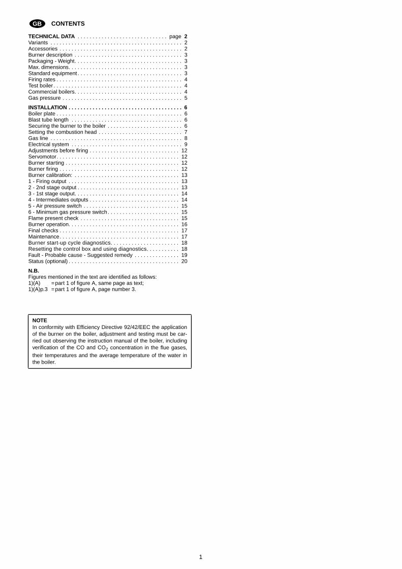
CONTENTS
TECHNICAL DATA
. . . . . . . . . . . . . . . . . . . . . . . . . . . . . . page
2
Variants . . . . . . . . . . . . . . . . . . . . . . . . . . . . . . . . . . . . . . . . . . . . 2Accessories . . . . . . . . . . . . . . . . . . . . . . . . . . . . . . . . . . . . . . . . . 2Burner description . . . . . . . . . . . . . . . . . . . . . . . . . . . . . . . . . . . . 3Packaging - Weight. . . . . . . . . . . . . . . . . . . . . . . . . . . . . . . . . . . . 3Max. dimensions. . . . . . . . . . . . . . . . . . . . . . . . . . . . . . . . . . . . . . 3Standard equipment . . . . . . . . . . . . . . . . . . . . . . . . . . . . . . . . . . . 3Firing rates . . . . . . . . . . . . . . . . . . . . . . . . . . . . . . . . . . . . . . . . . . 4Test boiler . . . . . . . . . . . . . . . . . . . . . . . . . . . . . . . . . . . . . . . . . . . 4Commercial boilers. . . . . . . . . . . . . . . . . . . . . . . . . . . . . . . . . . . . 4Gas pressure . . . . . . . . . . . . . . . . . . . . . . . . . . . . . . . . . . . . . . . . 5
INSTALLATION . . . . . . . . . . . . . . . . . . . . . . . . . . . . . . . . . . . . . . 6
Boiler plate . . . . . . . . . . . . . . . . . . . . . . . . . . . . . . . . . . . . . . . . . . 6Blast tube length . . . . . . . . . . . . . . . . . . . . . . . . . . . . . . . . . . . . . 6Securing the burner to the boiler . . . . . . . . . . . . . . . . . . . . . . . . . 6Setting the combustion head . . . . . . . . . . . . . . . . . . . . . . . . . . . . 7Gas line . . . . . . . . . . . . . . . . . . . . . . . . . . . . . . . . . . . . . . . . . . . . 8Electrical system . . . . . . . . . . . . . . . . . . . . . . . . . . . . . . . . . . . . . 9Adjustments before firing . . . . . . . . . . . . . . . . . . . . . . . . . . . . . . 12Servomotor. . . . . . . . . . . . . . . . . . . . . . . . . . . . . . . . . . . . . . . . . 12Burner starting . . . . . . . . . . . . . . . . . . . . . . . . . . . . . . . . . . . . . . 12Burner firing . . . . . . . . . . . . . . . . . . . . . . . . . . . . . . . . . . . . . . . . 12Burner calibration: . . . . . . . . . . . . . . . . . . . . . . . . . . . . . . . . . . . 131 - Firing output . . . . . . . . . . . . . . . . . . . . . . . . . . . . . . . . . . . . . 132 - 2nd stage output . . . . . . . . . . . . . . . . . . . . . . . . . . . . . . . . . . 133 - 1st stage output. . . . . . . . . . . . . . . . . . . . . . . . . . . . . . . . . . . 144 - Intermediates outputs . . . . . . . . . . . . . . . . . . . . . . . . . . . . . . 145 - Air pressure switch . . . . . . . . . . . . . . . . . . . . . . . . . . . . . . . . 156 - Minimum gas pressure switch. . . . . . . . . . . . . . . . . . . . . . . . 15Flame present check . . . . . . . . . . . . . . . . . . . . . . . . . . . . . . . . . 15Burner operation. . . . . . . . . . . . . . . . . . . . . . . . . . . . . . . . . . . . . 16Final checks . . . . . . . . . . . . . . . . . . . . . . . . . . . . . . . . . . . . . . . . 17Maintenance. . . . . . . . . . . . . . . . . . . . . . . . . . . . . . . . . . . . . . . . 17Burner start-up cycle diagnostics. . . . . . . . . . . . . . . . . . . . . . . 18Resetting the control box and using diagnostics. . . . . . . . . . . 18Fault - Probable cause - Suggested remedy . . . . . . . . . . . . . . . 19Status (optional) . . . . . . . . . . . . . . . . . . . . . . . . . . . . . . . . . . . . . 20
N.B.
Figures mentioned in the text are identified as follows:1)(A) =part 1 of figure A, same page as text;1)(A)p.3 =part 1 of figure A, page number 3.
NOTE
In conformity with Efficiency Directive 92/42/EEC the applicationof the burner on the boiler, adjustment and testing must be car-ried out observing the instruction manual of the boiler, includingverification of the CO and CO
2
concentration in the flue gases,their temperatures and the average temperature of the water inthe boiler.
GB
2
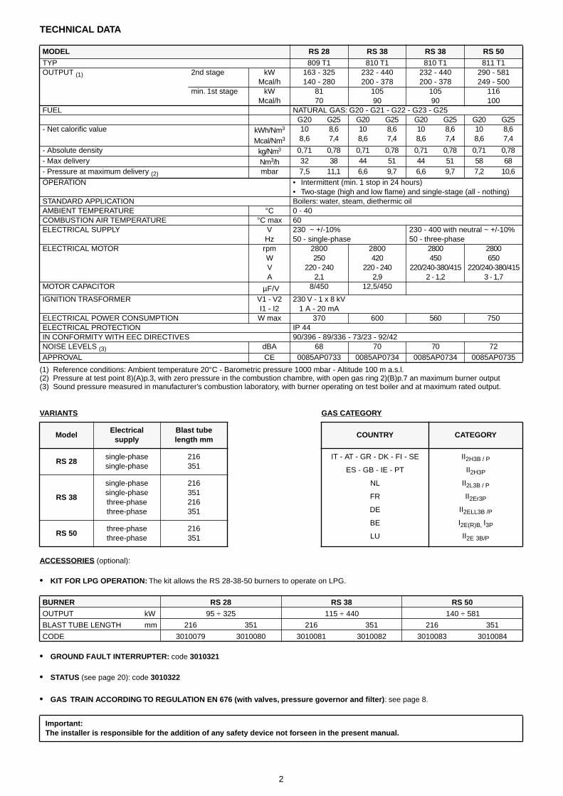
TECHNICAL DATA
(1) Reference conditions: Ambient temperature 20°C - Barometric pressure 1000 mbar - Altitude 100 m a.s.l.(2) Pressure at test point 8)(A)p.3, with zero pressure in the combustion chambre, with open gas ring 2)(B)p.7 an maximum burner output(3) Sound pressure measured in manufacturer’s combustion laboratory, with burner operating on test boiler and at maximum rated output.
ACCESSORIES
(optional):
•
KIT FOR LPG OPERATION:
The kit allows the RS 28-38-50 burners to operate on LPG.
•
GROUND FAULT INTERRUPTER:
code
3010321
•
STATUS
(see page 20):
code
3010322
•
GAS TRAIN ACCORDING TO REGULATION EN 676 (with valves, pressure governor and filter)
: see page 8.
MODEL RS 28 RS 38 RS 38 RS 50
TYP 809 T1 810 T1 810 T1 811 T1OUTPUT
(1)
2nd stage kW 163 - 325140 - 280
232 - 440200 - 378
232 - 440200 - 378
290 - 581249 - 500Mcal/h
min. 1st stage kWMcal/h
8170
10590
10590
116100
FUEL NATURAL GAS: G20 - G21 - G22 - G23 - G25G20 G25 G20 G25 G20 G25 G20 G25
- Net calorific value kWh/Nm
3
Mcal/Nm
3
108,6
8,67,4
108,6
8,67,4
108,6
8,67,4
108,6
8,67,4
- Absolute density kg/Nm
3
0,71 0,78 0,71 0,78 0,71 0,78 0,71 0,78- Max delivery Nm
3
/h 32 38 44 51 44 51 58 68- Pressure at maximum delivery
(2)
mbar 7,5 11,1 6,6 9,7 6,6 9,7 7,2 10,6OPERATION • Intermittent (min. 1 stop in 24 hours)
• Two-stage (high and low flame) and single-stage (all - nothing)STANDARD APPLICATION Boilers: water, steam, diethermic oilAMBIENT TEMPERATURE °C 0 - 40COMBUSTION AIR TEMPERATURE °C max 60ELECTRICAL SUPPLY V
Hz230 ~ +/-10%50 - single-phase
230 - 400 with neutral ~ +/-10%50 - three-phase
ELECTRICAL MOTOR rpmWVA
2800250
220 - 2402,1
2800420
220 - 2402,9
2800450
220/240-380/4152 - 1,2
2800650
220/240-380/4153 - 1,7
MOTOR CAPACITOR
µ
F/V 8/450 12,5/450
IGNITION TRASFORMER V1 - V2I1 - I2
230 V - 1 x 8 kV1 A - 20 mA
ELECTRICAL POWER CONSUMPTION W max 370 600 560 750ELECTRICAL PROTECTION IP 44IN CONFORMITY WITH EEC DIRECTIVES 90/396 - 89/336 - 73/23 - 92/42NOISE LEVELS
(3)
dBA 68 70 70 72APPROVAL CE 0085AP0733 0085AP0734 0085AP0734 0085AP0735
VARIANTS GAS CATEGORY
ModelElectrical
supplyBlast tubelength mm
COUNTRY CATEGORY
RS 28
single-phasesingle-phase
216351
IT - AT - GR - DK - FI - SE
ES - GB - IE - PT
NL
FR
DE
BE
LU
II
2H3B / P
II
2H3P
II
2L3B / P
II
2Er3P
II
2ELL3B /P
I
2E(R)B,
I
3P
II
2E
3B/P
RS 38
single-phasesingle-phasethree-phasethree-phase
216351216351
RS 50
three-phasethree-phase
216351
BURNER RS 28 RS 38 RS 50
OUTPUT kW 95 ÷ 325 115 ÷ 440 140 ÷ 581
BLAST TUBE LENGTH mm 216 351 216 351 216 351
CODE 3010079 3010080 3010081 3010082 3010083 3010084
Important:The installer is responsible for the addition of any safety device not forseen in the present manual.
3
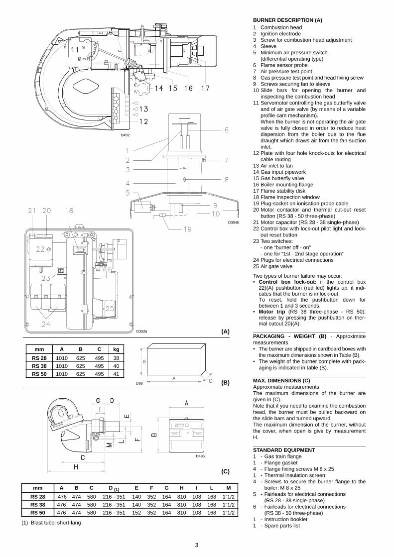
BURNER DESCRIPTION (A)
1 Combustion head2 Ignition electrode3 Screw for combustion head adjustment4 Sleeve5 Minimum air pressure switch
(differential operating type)6 Flame sensor probe7 Air pressure test point8 Gas pressure test point and head fixing screw9 Screws securing fan to sleeve10 Slide bars for opening the burner and
inspecting the combustion head11 Servomotor controlling the gas butterfly valve
and of air gate valve (by means of a variableprofile cam mechanism).When the burner is not operating the air gatevalve is fully closed in order to reduce heatdispersion from the boiler due to the fluedraught which draws air from the fan suctioninlet.
12 Plate with four hole knock-outs for electricalcable routing
13 Air inlet to fan14 Gas input pipework15 Gas butterfly valve16 Boiler mounting flange17 Flame stability disk18 Flame inspection window19 Plug-socket on ionisation probe cable20 Motor contactor and thermal cut-out reset
button (RS 38 - 50 three-phase)21 Motor capacitor (RS 28 - 38 single-phase)22 Control box with lock-out pilot light and lock-
out reset button23 Two switches:
- one “burner off - on”- one for “1st - 2nd stage operation”
24 Plugs for electrical connections25 Air gate valve
Two types of burner failure may occur:•
Control box lock-out:
if the control box22)(A) pushbutton (red led) lights up, it indi-cates that the burner is in lock-out.To reset, hold the pushbutton down forbetween 1 and 3 seconds.
•
Motor trip
(RS 38 three-phase - RS 50):release by pressing the pushbutton on ther-mal cutout 20)(A).
PACKAGING - WEIGHT (B)
- Approximatemeasurements• The burner are shipped in cardboard boxes with
the maximum dimensions shown in Table (B).• The weight of the burner complete with pack-
aging is indicated in table (B).
MAX. DIMENSIONS (C)
Approximate measurementsThe maximum dimensions of the burner aregiven in (C).Note that if you need to examine the combustionhead, the burner must be pulled backward onthe slide bars and turned upward.The maximum dimension of the burner, withoutthe cover, when open is give by measurementH.
STANDARD EQUIPMENT
1 - Gas train flange1 - Flange gasket4 - Flange fixing screws M 8 x 251 - Thermal insulation screen4 - Screws to secure the burner flange to the
boiler: M 8 x 255 - Fairleads for electrical connections
(RS 28 - 38 single-phase)6 - Fairleads for electrical connections
(RS 38 - 50 three-phase)1 - Instruction booklet1 - Spare parts list
(A)
mm A B C kg
RS 28 1010 625 495 38
RS 38 1010 625 495 40
RS 50 1010 625 495 41
(B)
(1) Blast tube: short-lang
mm A B C D (1) E F G H I L M
RS 28 476 474 580 216 - 351 140 352 164 810 108 168 1”1/2
RS 38 476 474 580 216 - 351 140 352 164 810 108 168 1”1/2
RS 50 476 474 580 216 - 351 152 352 164 810 108 168 1”1/2
(C)
D492
D88
D3045
D3026
D495
4
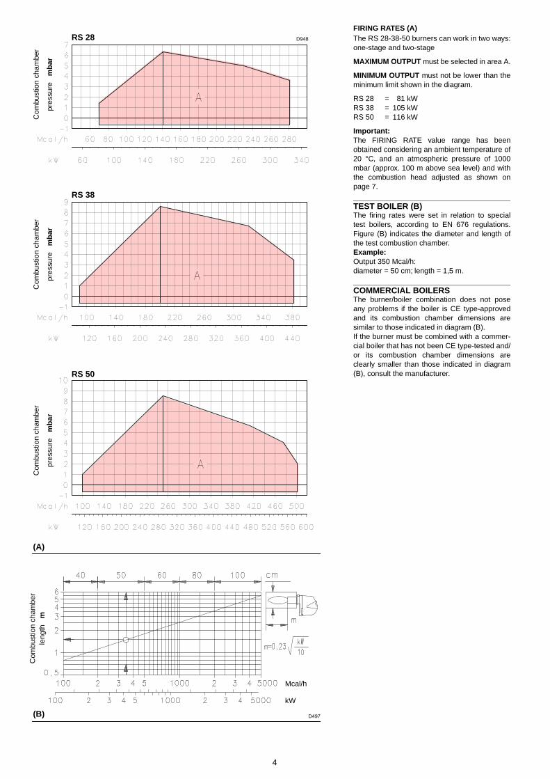
FIRING RATES (A)
The RS 28-38-50 burners can work in two ways:one-stage and two-stage
MAXIMUM OUTPUT
must be selected in area A.
MINIMUM OUTPUT
must not be lower than theminimum limit shown in the diagram.
RS 28 = 81 kWRS 38 = 105 kWRS 50 = 116 kW
Important:
The FIRING RATE value range has beenobtained considering an ambient temperature of20 °C, and an atmospheric pressure of 1000mbar (approx. 100 m above sea level) and withthe combustion head adjusted as shown onpage 7.
TEST BOILER (B)
The firing rates were set in relation to specialtest boilers, according to EN 676 regulations.Figure (B) indicates the diameter and length ofthe test combustion chamber.
Example:
Output 350 Mcal/h:diameter = 50 cm; length = 1,5 m.
COMMERCIAL BOILERS
The burner/boiler combination does not poseany problems if the boiler is CE type-approvedand its combustion chamber dimensions aresimilar to those indicated in diagram (B). If the burner must be combined with a commer-cial boiler that has not been CE type-tested and/or its combustion chamber dimensions areclearly smaller than those indicated in diagram(B), consult the manufacturer.
(A)
(B)
RS 28
RS 38
RS 50
D948
D497
Mcal/h
kW
pres
sure
m
bar
Com
bust
ion
cham
ber
pres
sure
m
bar
Com
bust
ion
cham
ber
pres
sure
m
bar
Com
bust
ion
cham
ber
Com
bust
ion
cham
ber
leng
th
m
5
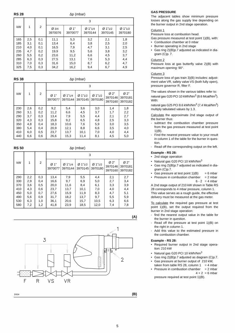
GAS PRESSURE
The adjacent tables show minimum pressurelosses along the gas supply line depending onthe burner output in 2nd stage operation.
Column 1Pressure loss at combustion head.Gas pressure measured at test point 1)(B), with:• Combustion chamber at 0 mbar• Burner operating in 2nd stage• Gas ring 2)(B)p.7 adjusted as indicated in dia-
gram (C)p. 7.
Column 2Pressure loss at gas butterfly valve 2)(B) withmaximum opening: 90°.
Column 3Pressure loss of gas train 3)(B) includes: adjust-ment valve VR, safety valve VS (both fully open),pressure governor R, filter F.
The values shown in the various tables refer to:
natural gas G20 PCI 10 kWh/Nm
3
(8.6 Mcal/Nm
3
).With:
natural gas G25 PCI 8.6 kWh/Nm
3
(7.4 Mcal/Nm
3
)multiply tabulated values by 1.3.
Calculate the approximate 2nd stage output ofthe burner thus:- subtract the combustion chamber pressure
from the gas pressure measured at test point1)(B).
- Find the nearest pressure value to your resultin column 1 of the table for the burner in ques-tion.
- Read off the corresponding output on the left.
Example - RS 28:
• 2nd stage operation
• Natural gas G20 PCI 10 kWh/Nm
3
• Gas ring 2)(B)p.7 adjusted as indicated in dia-gram (C)p.7.
• Gas pressure at test point 1)(B) = 6 mbar• Pressure in combustion chamber = 2 mbar
6 - 2 = 4 mbarA 2nd stage output of 210 kW shown in Table RS28 corresponds to 4 mbar pressure, column 1. This value serves as a rough guide, the effectivedelivery must be measured at the gas meter.
To calculate the required gas pressure at testpoint 1)(B), set the output required from theburner in 2nd stage operation:- find the nearest output value in the table for
the burner in question.- Read off the pressure at test point 1)(B) on
the right in column 1.- Add this value to the estimated pressure in
the combustion chamber.
Example - RS 28:
• Required burner output in 2nd stage opera-tion: 210 kW
• Natural gas G20 PCI 10 kWh/Nm
3
• Gas ring 2)(B)p.7 adjusted as diagram (C)p.7.• Gas pressure at burner output of 210 kW,
taken from table RS 28, column 1 = 4 mbar• Pressure in combustion chamber = 2 mbar
4 + 2 = 6 mbarpressure required at test point 1)(B).
(A)
(B)
RS 28 ∆p (mbar)
RS 38 ∆p (mbar)
RS 50 ∆p (mbar)
kW 1 2
3
Ø 3/43970076
Ø 1”3970077
Ø 1”1/43970144
Ø 1”1/23970145
Ø 1”1/23970180
165185210235260285310325
2,53,14,04,75,56,37,07,5
0,10,10,10,20,20,30,30,3
11,113,416,519,923,627,531,634,2
5,36,47,99,5
11,213,115,016,2
3,23,84,75,66,67,68,79,4
2,12,53,13,84,55,36,26,7
1,82,02,53,23,74,44,74,9
kW 1 2
3
Ø 1” 3970077
Ø 1”1/43970144
Ø 1”1/23970145
Ø 1”1/23970180
Ø 2”39701463970160
Ø 2”39701813970182
230260290320350380410440
2,63,13,74,34,85,46,06,6
0,20,20,30,30,40,40,50,6
9,211,213,415,818,320,923,726,6
5,46,67,99,2
10,612,113,715,3
3,64,55,56,57,68,8
10,111,4
3,03,74,44,85,96,67,08,1
1,41,72,12,53,03,54,04,5
1,82,22,73,33,54,04,45,0
kW 1 2
3
Ø 1” 3970077
Ø 1”1/43970144
Ø 1”1/23970145
Ø 1”1/23970180
Ø 2”39701463970160
Ø 2”39701813970182
290330370410450490530580
2,22,93,64,35,05,66,37,2
0,30,40,50,60,70,91,01,2
13,416,620,023,727,631,736,141,8
7,99,7
11,613,715,918,220,623,9
5,56,98,4
10,111,913,715,718,5
4,45,06,17,08,39,7
10,512,0
2,12,73,34,04,75,56,37,4
2,73,43,94,45,15,96,67,8
D934
6
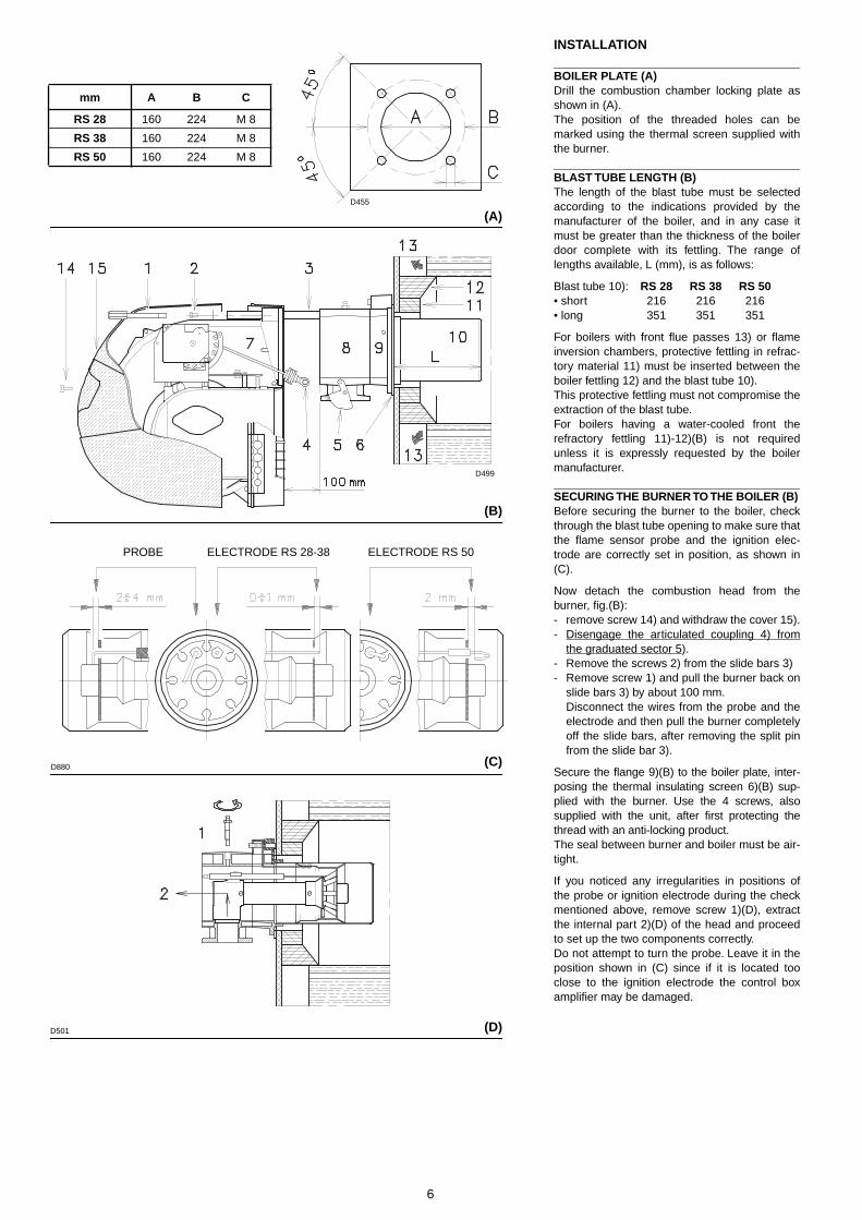
INSTALLATION
BOILER PLATE (A)
Drill the combustion chamber locking plate asshown in (A). The position of the threaded holes can bemarked using the thermal screen supplied withthe burner.
BLAST TUBE LENGTH (B)
The length of the blast tube must be selectedaccording to the indications provided by themanufacturer of the boiler, and in any case itmust be greater than the thickness of the boilerdoor complete with its fettling. The range oflengths available, L (mm), is as follows:
Blast tube 10):
RS 28 RS 38 RS 50
• short 216 216 216• long 351 351 351
For boilers with front flue passes 13) or flameinversion chambers, protective fettling in refrac-tory material 11) must be inserted between theboiler fettling 12) and the blast tube 10). This protective fettling must not compromise theextraction of the blast tube.For boilers having a water-cooled front therefractory fettling 11)-12)(B) is not requiredunless it is expressly requested by the boilermanufacturer.
SECURING THE BURNER TO THE BOILER (B)
Before securing the burner to the boiler, checkthrough the blast tube opening to make sure thatthe flame sensor probe and the ignition elec-trode are correctly set in position, as shown in(C).
Now detach the combustion head from theburner, fig.(B):- remove screw 14) and withdraw the cover 15).- Disengage the articulated coupling 4) from
the graduated sector 5).- Remove the screws 2) from the slide bars 3)- Remove screw 1) and pull the burner back on
slide bars 3) by about 100 mm.Disconnect the wires from the probe and theelectrode and then pull the burner completelyoff the slide bars, after removing the split pinfrom the slide bar 3).
Secure the flange 9)(B) to the boiler plate, inter-posing the thermal insulating screen 6)(B) sup-plied with the burner. Use the 4 screws, alsosupplied with the unit, after first protecting thethread with an anti-locking product.The seal between burner and boiler must be air-tight.
If you noticed any irregularities in positions ofthe probe or ignition electrode during the checkmentioned above, remove screw 1)(D), extractthe internal part 2)(D) of the head and proceedto set up the two components correctly. Do not attempt to turn the probe. Leave it in theposition shown in (C) since if it is located tooclose to the ignition electrode the control boxamplifier may be damaged.
(A)
(B)
mm A B C
RS 28 160 224 M 8
RS 38 160 224 M 8
RS 50 160 224 M 8
(C)
(D)
PROBE ELECTRODE RS 28-38 ELECTRODE RS 50
D455
D499
D880
D501
7
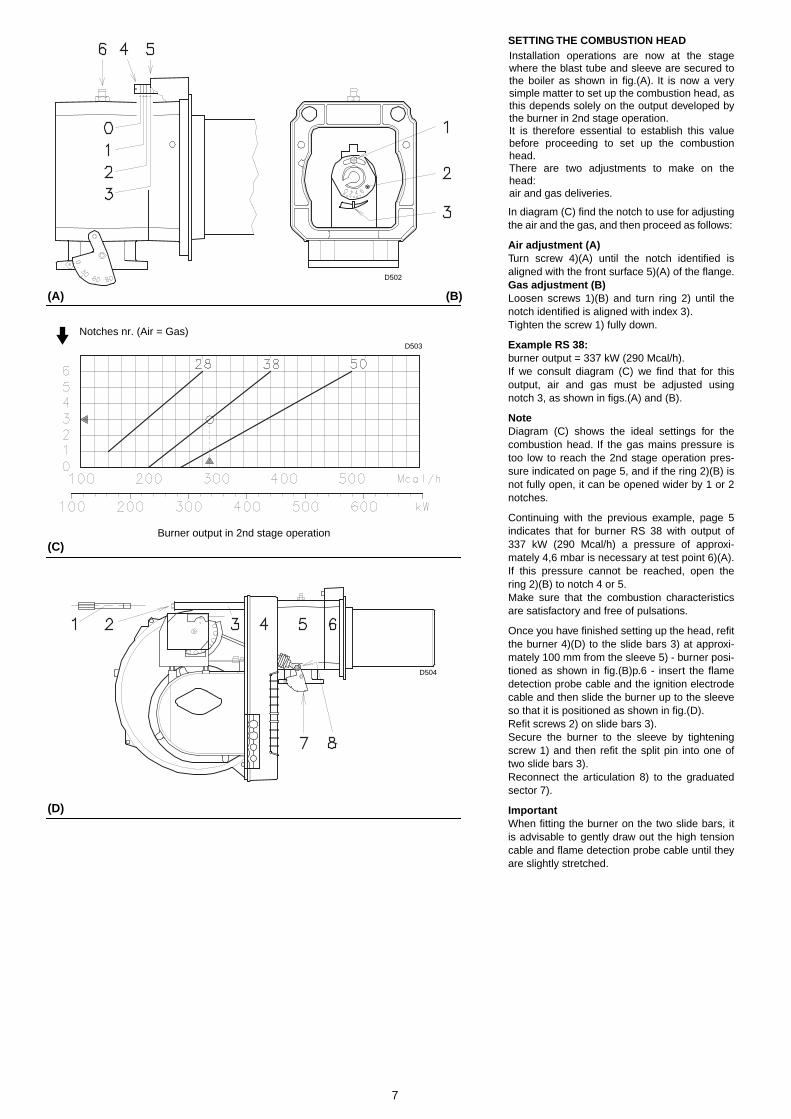
SETTING THE COMBUSTION HEAD
Installation operations are now at the stagewhere the blast tube and sleeve are secured tothe boiler as shown in fig.(A). It is now a verysimple matter to set up the combustion head, asthis depends solely on the output developed bythe burner in 2nd stage operation. It is therefore essential to establish this valuebefore proceeding to set up the combustionhead. There are two adjustments to make on thehead: air and gas deliveries.
In diagram (C) find the notch to use for adjustingthe air and the gas, and then proceed as follows:
Air adjustment (A)
Turn screw 4)(A) until the notch identified isaligned with the front surface 5)(A) of the flange.
Gas adjustment (B)
Loosen screws 1)(B) and turn ring 2) until thenotch identified is aligned with index 3). Tighten the screw 1) fully down.
Example RS 38:
burner output = 337 kW (290 Mcal/h).If we consult diagram (C) we find that for thisoutput, air and gas must be adjusted usingnotch 3, as shown in figs.(A) and (B).
Note
Diagram (C) shows the ideal settings for thecombustion head. If the gas mains pressure istoo low to reach the 2nd stage operation pres-sure indicated on page 5, and if the ring 2)(B) isnot fully open, it can be opened wider by 1 or 2notches.
Continuing with the previous example, page 5indicates that for burner RS 38 with output of337 kW (290 Mcal/h) a pressure of approxi-mately 4,6 mbar is necessary at test point 6)(A).If this pressure cannot be reached, open thering 2)(B) to notch 4 or 5. Make sure that the combustion characteristicsare satisfactory and free of pulsations.
Once you have finished setting up the head, refitthe burner 4)(D) to the slide bars 3) at approxi-mately 100 mm from the sleeve 5) - burner posi-tioned as shown in fig.(B)p.6 - insert the flamedetection probe cable and the ignition electrodecable and then slide the burner up to the sleeveso that it is positioned as shown in fig.(D). Refit screws 2) on slide bars 3). Secure the burner to the sleeve by tighteningscrew 1) and then refit the split pin into one oftwo slide bars 3). Reconnect the articulation 8) to the graduatedsector 7).
Important
When fitting the burner on the two slide bars, itis advisable to gently draw out the high tensioncable and flame detection probe cable until theyare slightly stretched.
(A)
(C)
(B)
(D)
Burner output in 2nd stage operation
Notches nr. (Air = Gas)
D502
D503
D504
8
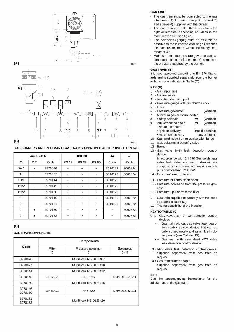
GAS LINE
• The gas train must be connected to the gasattachment 1)(A), using flange 2), gasket 3)and screws 4) supplied with the burner.
• The gas train can enter the burner from theright or left side, depending on which is themost convenient, see fig.(A).
• Gas solenoids 8)-9)(B) must be as close aspossible to the burner to ensure gas reachesthe combustion head within the safety timerange of 3 s.
• Make sure that the pressure governor calibra-tion range (colour of the spring) comprisesthe pressure required by the burner.
GAS TRAIN (B)It is type-approved according to EN 676 Stand-ards and is supplied separately from the burnerwith the code indicated in Table (C).
KEY (B)1 - Gas input pipe2 - Manual valve3 - Vibration damping joint4 - Pressure gauge with pushbutton cock5 - Filter6 - Pressure governor (vertical)7 - Minimum gas pressure switch8 - Safety solenoid VS (vertical)9 - Adjustment solenoid VR (vertical)
Two adjustments:• ignition delivery (rapid opening)• maximum delivery (slow opening)
10 - Standard issue burner gasket with flange11 - Gas adjustment butterfly valve12 - Burner13 - Gas valve 8)-9) leak detection control
device. In accordance with EN 676 Standards, gasvalve leak detection control devices arecompulsory for burners with maximum out-puts of more than 1200 kW.
14 - Gas train/burner adaptor.
P1 - Pressure at combustion head P2 - Pressure down-line from the pressure gov-
ernor P3 - Pressure up-line from the filter
L - Gas train supplied separately with the codeindicated in Table (C)
L1 - The responsibility of the installer
KEY TO TABLE (C)C.T. =Gas valves 8) - 9) leak detection control
devices:- = Gas train without gas valve leak detec-
tion control device; device that can beordered separately and assembled sub-sequently (see Column 13).
♦ = Gas train with assembled VPS valveleak detection control device.
13 =VPS valve leak detection control device.Supplied separately from gas train onrequest.
14 =Gas train/burner adaptor. Supplied separately from gas train onrequest.
NoteSee the accompanying instructions for theadjustment of the gas train.
(A)
(B)
(C)
GAS BURNERS AND RELEVANT GAS TRAINS APPROVED ACCORDING TO EN 676
Gas train L Burner 13 14
Ø C.T. Code RS 28 RS 38 RS 50 Code Code
3/4” − 3970076 • − − 3010123 3000824
1” − 3970077 • • • 3010123 3000824
1”1/4 − 3970144 • • • 3010123 −
1”1/2 − 3970145 • • • 3010123 −
1”1/2 − 3970180 • • • 3010123 −
2” − 3970146 − • • 3010123 3000822
2” − 3970181 − • • 3010123 3000822
2” ♦ 3970160 − • • − 3000822
2” ♦ 3970182 − • • − 3000822
GAS TRAIN COMPONENTS
Code
Components
Filter5
Pressure governor6
Solenoids8 - 9
3970076 Multiblock MB DLE 407
3970077 Multiblock MB DLE 410
3970144 Multiblock MB DLE 412
3970145 GF 515/1 FRS 515 DMV DLE 512/11
3970180 Multiblock MB DLE 415
39701463970160
GF 520/1 FRS 520 DMV DLE 520/11
39701813970182
Multiblock MB DLE 420
D505
D935

9
ELECTRICAL SYSTEM
ELECTRICAL SYSTEM as set up by the manu-facturer
LAYOUT (A)Burner RS 28 (single-phase)
LAYOUT (B)Burner RS 38 (single-phase)
LAYOUT (C)Burners RS 38 - 50 (three-phase)
• Models RS 38 and RS 50 leave the factorypreset for 400 V power supply.
• If 230 V power supply is used, change themotor connection from star to delta andchange the setting of the thermal cut-out aswell.
Key to Layouts (A) - (B) - (C)C - CapacitorCMV - Motor contactorF1 - Protection against radio interferenceDA - Control box (Landis RMG)I1 - Switch: burner off - onI2 - Switch: 1st - 2nd stage operationMV - Fan motorPA - Air pressure switchRT - Thermal cut-outSM - ServomotorSO - Ionisation probeSP - Plug-socketTA - Ignition transformerTB - Burner groundXP1 - Connector for STATUSXP4 - 4 pole socketXP5 - 5 pole socketXP6 - 6 pole socketXP7 - 7 pole socket
ATTENTIONIn the case of phase-phase feed, a bridgemust be fitted on the control box terminal stripbetween terminal 6 and the earth terminal.
(A)
(B)
ELECTRICAL EQUIPMENT FACTORY-SETRS 28 single-phase
ELECTRICAL EQUIPMENT FACTORY-SETRS 38 single-phase
ELECTRICAL EQUIPMENT FACTORY-SETRS 38 three-phase - RS 50
(C)
D3012
D3013
D3014
Ner
oB
ianc
oB
lu

10
ELECTRICAL CONNECTIONSUse flexible cables according to EN 60 335-1Regulations:• if in PVC sheath, use at least H05 VV-F• if in rubber sheath, use at least H05 RR-F.All the wires to connect to the burner plugs 7)(A)must enter through the supplied fairleads, whichmust be fitted into the relevant holes in the lefthand or right hand plate. To do this, first unscrewscrews 8), then split the plate into its parts 9)and 10) and remove the menbrane press-outsfrom the holes.The fairleads and hole press-outs can be in vari-ous ways; the following lists show one possiblesolution:
RS 28 und RS 38 single-phase1 - Pg 11 Single-phase power supply 2 - Pg 11 Gas valves3 - Pg 9 Remote control device TL4 - Pg 9 Remote control device TR 5 - Pg 11 Gas pressure switch or gas valve
leak detection control device
RS 38 three-phase and RS 501 - Pg 11 Three-phase power supply 2 - Pg 11 Single-phase power supply3 - Pg 9 Remote control device TL4 - Pg 9 Remote control device TR 5 - Pg 11 Gas valves6 - Pg 11 Gas pressure switch or gas valve
leak detection control device
LAYOUT (B) - The RS 28 - 38 Models electricalconnection single-phase power supply without leak detection control device.
LAYOUT (C) The RS 28 - 38 Models electricalconnection single-phase power supply with VPS leak detection control device. Gas valve leak detection control takes placeimmediately before every burner start-up.
Key to layouts (B) - (C)h1 - 1st stage hourcounterh2 - 2nd stage hourcounterIN - Burner manual stop switchXP- Plug for leak detection control deviceX4 - 4 pole plugX6 - 6 pole plugX7 - 7 pole plugPC- Gas pressure switch for leak detection con-
trol devicePG- Min. gas pressure switchS - Remote lock-out signalS1 - Remote lock-out signal of leak detection
control deviceTR- High-low mode load remote control system:
controls operating stages 1 and 2. If the burner is to be set up for single stageoperation, replace of remote control deviceTR with a jumper.
TL - Load limit remote control system: shuts down the burner when the boiler tem-perature or pressure reaches the presetvalue.
TS - Safety load control system: operates when TL is faulty
VR- Adjustment valveVS- Safety valve
(A)
(B)
RS 28 - RS 38 single-phase without leak detection control device
RS 28 - RS 38 single-phase with leak detection control device VPS
(C)
D3027
D940
D941

11
LAYOUT (A) - The RS 38 - 50 Models electrical connection three-phase power supply with-out leak detection control device
LAYOUT (B) - The RS 38 - 50 Models electri-cal connection three-phase power supplywith VPS leak detection control device.Gas valve leak detection control takes placeimmediately before every burner starting.
Key to layouts (A) - (B)h1 - 1st stage hourcounterh2 - 2nd stage hourcounterIN - Burner manual stop switchXP- Plug for leak detection control deviceX4 - 4 pole plugX5 - 5 pole plugX6 - 6 pole plugX7 - 7 pole plugPC- Gas pressure switch for leak detection con-
trol devicePG- Min. gas pressure switchS - Remote lock-out signalS1 - Remote lock-out signal of leak detection
control deviceTR- High-low mode load remote control system:
controls operating stages 1 and 2. If the burner is to be set up for single stageoperation, replace of remote control deviceTR with a jumper.
TL - Load limit remote control system: shuts down the burner when the boiler tem-perature or pressure reaches the presetvalue.
TS - Safety load control system: operates when TL is faulty
VR- Adjustment valveVS- Safety valve
LAYOUT (C)Calibration of thermal cut-out 20)(A)p.3This is required to avoid motor burn-out in theevent of a significant increase in power absorp-tion caused by a missing phase.• If the motor is star-powered, 400 V, the cursor
should be positioned to "MIN".• If the motor is delta-powered, 230 V, the cur-
sor should be positioned to "MAX".Even if the scale of the thermal cut-out does notinclude rated motor absorption at 400 V, protec-tion is still ensured in any case.
N.B.• The RS 38 and RS 50 three-phase leave the
factory preset for 400 V power supply. If 230 Vpower supply is used, change the motor con-nection from star to delta and change the set-ting of the thermal cut-out as well.
• The RS 28-38-50 burners have been type-approved for intermittent operation. Thismeans they should compulsorily be stoppedat least once every 24 hours to enable thecontrol box to check its own efficiency at start-up. Burner halts are normally provided forautomatically by the boiler load control sys-tem. If this is not the case, a time switchshould be fitted in series to IN to provide forburner shut-down at least once every 24hours.
• The RS 28-38-50 burners are factory set fortwo-stage operation and must therefore beconnected to control device TR. Alternatively,if single stage operation is required, instead ofcontrol device TR install a jumper leadbetween terminals T6 and T8 of connector X4.
WARNING: Do not invert the neutral withthe phase wire in the electricity supplyline. Inverting the wires will make theburner go into lock-out because of firingfailure.
(A)
(B)
RS 38 - RS 50 three-phase without leak detection control device
RS 38 - RS 50 three-phase without leak detection control device VPS
(C)
CALIBRATION OF THERMAL RELAYRS 38 three-phase - RS 50
D943
D944
D867
12
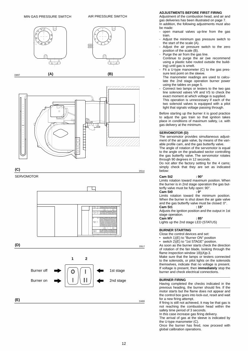
ADJUSTMENTS BEFORE FIRST FIRINGAdjustment of the combustion head, and air andgas deliveries has been illustrated on page 7.In addition, the following adjustments must alsobe made:- open manual valves up-line from the gas
train.- Adjust the minimum gas pressure switch to
the start of the scale (A).- Adjust the air pressure switch to the zero
position of the scale (B).- Purge the air from the gas line.
Continue to purge the air (we recommendusing a plastic tube routed outside the build-ing) until gas is smelt.
- Fit a U-type manometer (C) to the gas pres-sure test point on the sleeve.The manometer readings are used to calcu-late the 2nd stage operation burner powerusing the tables on page 5.
- Connect two lamps or testers to the two gasline solenoid valves VR and VS to check theexact moment at which voltage is supplied.This operation is unnecessary if each of thetwo solenoid valves is equipped with a pilotlight that signals voltage passing through.
Before starting up the burner it is good practiceto adjust the gas train so that ignition takesplace in conditions of maximum safety, i.e. withgas delivery at the minimum.
SERVOMOTOR (D)The servomotor provides simultaneous adjust-ment of the air gate valve, by means of the vari-able profile cam, and the gas butterfly valve.The angle of rotation of the servomotor is equalto the angle on the graduated sector controllingthe gas butterfly valve. The servomotor rotatesthrough 90 degrees in 12 seconds.Do not alter the factory setting for the 4 cams;simply check that they are set as indicatedbelow:
Cam St2 : 90°Limits rotation toward maximum position. Whenthe burner is in 2nd stage operation the gas but-terfly valve must be fully open: 90°.Cam St0 : 0°Limits rotation toward the minimum position.When the burner is shut down the air gate valveand the gas butterfly valve must be closed: 0°.Cam St1 : 15°Adjusts the ignition position and the output in 1ststage operation.Cam MV : 85°Lights up the 2nd stage LED (STATUS)
BURNER STARTINGClose the control devices and set:• switch 1)(E) to "Burner ON" position• switch 2)(E) to "1st STAGE" position.As soon as the burner starts check the directionof rotation of the fan blade, looking through theflame inspection window 18)(A)p.3.Make sure that the lamps or testers connectedto the solenoids, or pilot lights on the solenoidsthemselves, indicate that no voltage is present.If voltage is present, then immediately stop theburner and check electrical connections.
BURNER FIRINGHaving completed the checks indicated in theprevious heading, the burner should fire. If themotor starts but the flame does not appear andthe control box goes into lock-out, reset and waitfor a new firing attempt. If firing is still not achieved, it may be that gas isnot reaching the combustion head within thesafety time period of 3 seconds. In this case increase gas firing delivery. The arrival of gas at the sleeve is indicated bythe U-type manometer (C).Once the burner has fired, now proceed withglobal calibration operations.
(A)
(C)
MIN GAS PRESSURE SWITCH AIR PRESSURE SWITCH
SERVOMOTOR
(D)
1 2
Burner off
Burner on
1st stage
2nd stage
(E)
(B)D897
D514
D517
D469
13
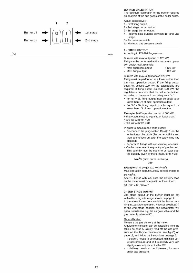
BURNER CALIBRATIONThe optimum calibration of the burner requiresan analysis of the flue gases at the boiler outlet.
Adjust successively:1 - First firing output2 - 2nd stage burner output3 - 1st stage burner output4 - Intermediate outputs between 1st and 2nd
stage5 - Air pressure switch6 - Minimum gas pressure switch
1 - FIRING OUTPUTAccording to EN 676 Regulations:
Burners with max. output up to 120 kWFiring can be performed at the maximum opera-tion output level. Example:• Max. operation output : 120 kW• Max. firing output : 120 kW
Burners with max. output above 120 kWFiring must be performed at a lower output thanthe max. operation output. If the firing outputdoes not exceed 120 kW, no calculations arerequired. If firing output exceeds 120 kW, theregulations prescribe that the value be definedaccording to the control box safety time "ts":• for "ts" = 2s, firing output must be equal to or
lower than 1/2 of max. operation output.• For "ts" = 3s, firing output must be equal to or
lower than 1/3 of max. operation output.
Example: MAX operation output of 600 kW.Firing output must be equal to or lower than:• 300 kW with "ts" = 2s• 200 kW with "ts" = 3s
In order to measure the firing output:- Disconnect the plug-socket 19)(A)p.3 on the
ionization probe cable (the burner will fire andthen go into lock-out after the safety time haselapsed).
- Perform 10 firings with consecutive lock-outs.- On the meter read the quantity of gas burned.
This quantity must be equal to or lower thanthe quantity given by the formula, for ts = 3s:
Example for G 20 gas (10 kWh/Nm3):Max. operation output: 600 kW corresponding to
60 Nm3/h.After 10 firings with lock-outs, the delivery readon the meter must be equal to or lower than:
60 : 360 = 0,166 Nm3.
2 - 2ND STAGE OUTPUT2nd stage output of the burner must be setwithin the firing rate range shown on page 4.In the above instructions we left the burner run-ning in 1st stage operation. Now set switch 2)(A)to the 2nd stage position: the servomotor willopen, simultaneously, the air gate valve and thegas butterfly valve to 90°.
Gas calibrationMeasure the gas delivery at the meter.A guideline indication can be calculated from thetables on page 5, simply read off the gas pres-sure on the U-type manometer, see fig.(C) onpage 12, and follow the instructions on page 5.- If delivery needs to be reduced, diminish out-
let gas pressure and, if it is already very low,slightly close adjustment valve VR.
- If delivery needs to be increased, increaseoutlet gas pressure.
(A)
1 2
Burner off
Burner on
1st stage
2nd stage
D469
Nm3/h (max. burner delivery )360
14
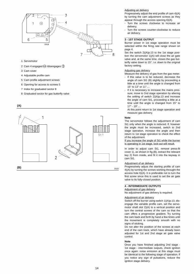
Adjusting air deliveryProgressively adjust the end profile of cam 4)(A)by turning the cam adjustment screws as theyappear through the access opening 6)(A).- Turn the screws clockwise to increase air
delivery.- Turn the screws counter-clockwise to reduce
air delivery.
3 - 1ST STAGE OUTPUTBurner power in 1st stage operation must beselected within the firing rate range shown onpage 4.Set the switch 2)(A)p.13 to the 1st stage posi-tion: the servomotor 1)(A) will close the air gatevalve and, at the same time, closes the gas but-terfly valve down to 15°, i.e. down to the originalfactory setting.
Adjusting gas deliveryMeasure the delivery of gas from the gas meter.- If this value is to be reduced, decrease the
angle of cam St1 (B) slightly by proceeding alittle at a time until the angle is changed from15° to 13° or 11°....
- If it is necessary to increase the mains pres-sure, move to 2nd stage operation by alteringthe setting of switch 2)(A)p.13 and increasethe angle of cam St1, proceeding a little at atime until the angle is changed from 15° to17° - 19°....At this point return to 1st stage operation andmeasure gas delivery.
NoteThe servomotor follows the adjustment of camSt1 only when the angle is reduced. If, howeverthe angle must be increased, switch to 2ndstage operation, increase the angle and thenreturn to 1st stage operation to check the effectof the adjustment.If you increase the angle of St1 while the burneris operating in 1st stage, lock-out will result.
In order to adjust cam St1, remove press-fitcover 1), as shown in fig.(B), extract the relevantkey 2) from inside, and fit it into the keyway incam St1.
Adjustment of air deliveryProgressively adjust the starting profile of cam4)(A) by turning the screws working throught theaccess hole 6)(A). It is preferable not to turn thefirst screw since this is used to set the air gatevalve to its fully-closed position.
4 - INTERMEDIATE OUTPUTSAdjustment of gas deliveryNo adjustment of gas delivery is required.
Adjustment of air deliverySwitch off the burner using switch 1)(A)p.13, dis-engage the variable profile cam, set the servo-motor shaft slot 2)(A) to a vertical position andturn the central screws of the cam so that thecam offers a progressive gradient. Try turningthe cam back and forth by hand a few times untilthe movement is completely smooth with nosigns of sticking.Do not alter the position of the screws at eachend of the cam track, which have already beenadjusted for 1st and 2nd stage air gate valvecontrol.
NoteOnce you have finished adjusting 2nd stage -1st stage - intermediate outputs, check ignitiononce again: noise emission at this stage mustbe identical to the following stage of operation. Ifyou notice any sign of pulsations, reduce theignition stage delivery.
(B)
(A)
1 Servomotor
2 Cam 4 engaged /disengages
3 Cam cover
4 Adjustable profile cam
5 Cam profile adjustment screws
6 Opening for access to screws 5
7 Index for graduated sector 8
8 Graduated sector for gas butterfly valve
D518
D520
15
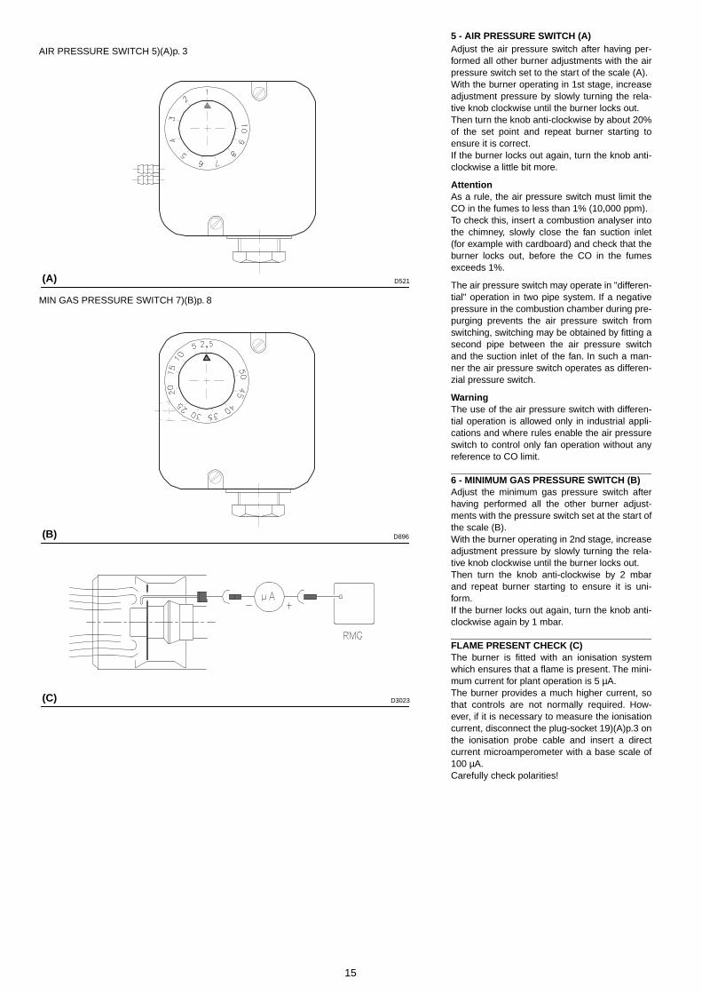
5 - AIR PRESSURE SWITCH (A)Adjust the air pressure switch after having per-formed all other burner adjustments with the airpressure switch set to the start of the scale (A).With the burner operating in 1st stage, increaseadjustment pressure by slowly turning the rela-tive knob clockwise until the burner locks out.Then turn the knob anti-clockwise by about 20%of the set point and repeat burner starting toensure it is correct.If the burner locks out again, turn the knob anti-clockwise a little bit more.
AttentionAs a rule, the air pressure switch must limit theCO in the fumes to less than 1% (10,000 ppm).To check this, insert a combustion analyser intothe chimney, slowly close the fan suction inlet(for example with cardboard) and check that theburner locks out, before the CO in the fumesexceeds 1%.
The air pressure switch may operate in "differen-tial" operation in two pipe system. If a negativepressure in the combustion chamber during pre-purging prevents the air pressure switch fromswitching, switching may be obtained by fitting asecond pipe between the air pressure switchand the suction inlet of the fan. In such a man-ner the air pressure switch operates as differen-zial pressure switch.
WarningThe use of the air pressure switch with differen-tial operation is allowed only in industrial appli-cations and where rules enable the air pressureswitch to control only fan operation without anyreference to CO limit.
6 - MINIMUM GAS PRESSURE SWITCH (B)Adjust the minimum gas pressure switch afterhaving performed all the other burner adjust-ments with the pressure switch set at the start ofthe scale (B).With the burner operating in 2nd stage, increaseadjustment pressure by slowly turning the rela-tive knob clockwise until the burner locks out.Then turn the knob anti-clockwise by 2 mbarand repeat burner starting to ensure it is uni-form.If the burner locks out again, turn the knob anti-clockwise again by 1 mbar.
FLAME PRESENT CHECK (C)The burner is fitted with an ionisation systemwhich ensures that a flame is present. The mini-mum current for plant operation is 5 µA. The burner provides a much higher current, sothat controls are not normally required. How-ever, if it is necessary to measure the ionisationcurrent, disconnect the plug-socket 19)(A)p.3 onthe ionisation probe cable and insert a directcurrent microamperometer with a base scale of100 µA. Carefully check polarities!
(A)
AIR PRESSURE SWITCH 5)(A)p. 3
MIN GAS PRESSURE SWITCH 7)(B)p. 8
(B)
(C)
D521
D896
D3023
16
BURNER OPERATION
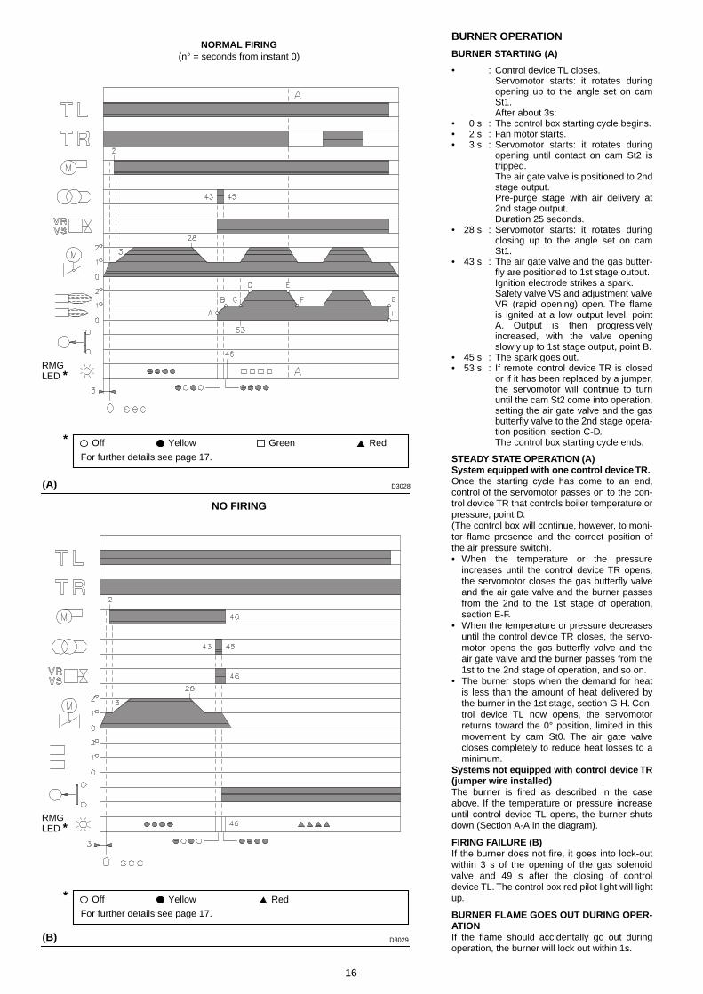
BURNER STARTING (A)
• : Control device TL closes.Servomotor starts: it rotates duringopening up to the angle set on camSt1.After about 3s:
• 0 s : The control box starting cycle begins.• 2 s : Fan motor starts.• 3 s : Servomotor starts: it rotates during
opening until contact on cam St2 istripped.The air gate valve is positioned to 2ndstage output.Pre-purge stage with air delivery at2nd stage output.Duration 25 seconds.
• 28 s : Servomotor starts: it rotates duringclosing up to the angle set on camSt1.
• 43 s : The air gate valve and the gas butter-fly are positioned to 1st stage output.Ignition electrode strikes a spark.Safety valve VS and adjustment valveVR (rapid opening) open. The flameis ignited at a low output level, pointA. Output is then progressivelyincreased, with the valve openingslowly up to 1st stage output, point B.
• 45 s : The spark goes out.• 53 s : If remote control device TR is closed
or if it has been replaced by a jumper,the servomotor will continue to turnuntil the cam St2 come into operation,setting the air gate valve and the gasbutterfly valve to the 2nd stage opera-tion position, section C-D.The control box starting cycle ends.
STEADY STATE OPERATION (A)System equipped with one control device TR.Once the starting cycle has come to an end,control of the servomotor passes on to the con-trol device TR that controls boiler temperature orpressure, point D.(The control box will continue, however, to moni-tor flame presence and the correct position ofthe air pressure switch).• When the temperature or the pressure
increases until the control device TR opens,the servomotor closes the gas butterfly valveand the air gate valve and the burner passesfrom the 2nd to the 1st stage of operation,section E-F.
• When the temperature or pressure decreasesuntil the control device TR closes, the servo-motor opens the gas butterfly valve and theair gate valve and the burner passes from the1st to the 2nd stage of operation, and so on.
• The burner stops when the demand for heatis less than the amount of heat delivered bythe burner in the 1st stage, section G-H. Con-trol device TL now opens, the servomotorreturns toward the 0° position, limited in thismovement by cam St0. The air gate valvecloses completely to reduce heat losses to aminimum.
Systems not equipped with control device TR(jumper wire installed)The burner is fired as described in the caseabove. If the temperature or pressure increaseuntil control device TL opens, the burner shutsdown (Section A-A in the diagram).
FIRING FAILURE (B)If the burner does not fire, it goes into lock-outwithin 3 s of the opening of the gas solenoidvalve and 49 s after the closing of controldevice TL. The control box red pilot light will lightup.
BURNER FLAME GOES OUT DURING OPER-ATIONIf the flame should accidentally go out duringoperation, the burner will lock out within 1s.
(A)
(B)
NORMAL FIRING(n° = seconds from instant 0)
NO FIRING
D3028
D3029
RMGLED *
Off Yellow Green Red
For further details see page 17.
*
Off Yellow Red
For further details see page 17.
*
RMGLED *
17
FINAL CHECKS (with burner running)• Disconnect one of the wires on the minimum
gas pressure switch:• Open remote control device TL:• Open remote control device TS:the burner must stop
• Disconnect the common wire P from the airpressure switch:
• Disconnect the ionisation probe lead:the burner must lock out
• Make sure that the mechanical locking sys-tems on the various adjustment devices arefully tightened.
MAINTENANCECombustionThe optimum calibration of the burner requiresan analysis of the flue gases. Significant differ-ences with respect to the previous measure-ments indicate the points where more careshould be exercised during maintenance.
Gas leaksMake sure that there are no gas leaks on thepipework between the gas meter and the burner.
Gas filterChange the gas filter when it is dirty.
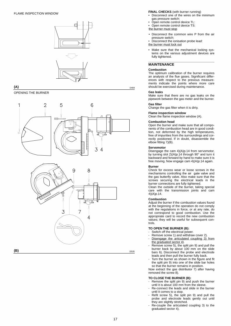
Flame inspection windowClean the flame inspection window (A).
Combustion headOpen the burner and make sure that all compo-nents of the combustion head are in good condi-tion, not deformed by the high temperatures,free of impurities from the surroundings and cor-rectly positioned. If in doubt, disassemble theelbow fitting 7)(B).
ServomotorDisengage the cam 4)(A)p.14 from servomotor,by turning slot 2)(A)p.14 through 90° and turn itbackward and forward by hand to make sure it isfree moving. Now engage cam 4)(A)p.14 again.
BurnerCheck for excess wear or loose screws in themechanisms controlling the air gate valve andthe gas butterfly valve. Also make sure that thescrews securing the electrical leads in theburner connections are fully tightened.Clean the outside of the burner, taking specialcare with the transmission joints and cam4)(A)p.14.
CombustionAdjust the burner if the combustion values foundat the beginning of the operation do not complywith the regulations in force, or at any rate, donot correspond to good combustion. Use theappropriate card to record the new combustionvalues; they will be useful for subsequent con-trols.
TO OPEN THE BURNER (B):- Switch off the electrical power.- Remove screw 1) and withdraw cover 2).- Disengage the articulated coupling 3) from
the graduated sector 4).- Remove screw 5), the split pin 9) and pull the
burner back by about 100 mm on the slidebars 6). Disconnect the probe and electrodeleads and then pull the burner fully back.
- Turn the burner as shown in the figure and fitthe split pin 9) into one of the slide bar holesso that the burner remains in position.
Now extract the gas distributor 7) after havingremoved the screw 8).
TO CLOSE THE BURNER (B):- Remove the split pin 9) and push the burner
until it is about 100 mm from the sleeve. - Re-connect the leads and slide in the burner
until it comes to a stop.- Refit screw 5), the split pin 9) and pull the
probe and electrode leads gently out untilthey are slightly stretched.
- Re-couple the articulated coupling 3) to thegraduated sector 4).
(A)
(B)
FLAME INSPECTION WINDOW
OPENING THE BURNER
D484
D535
18
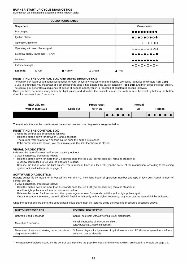
BURNER START-UP CYCLE DIAGNOSTICSDuring start-up, indication is according to the followin table:
RESETTING THE CONTROL BOX AND USING DIAGNOSTICSThe control box features a diagnostics function through which any causes of malfunctioning are easily identified (indicator: RED LED).To use this function, you must wait at least 10 seconds once it has entered the safety condition (lock-out ), and then press the reset button. The control box generates a sequence of pulses (1 second apart), which is repeated at constant 3-second intervals. Once you have seen how many times the light pulses and identified the possible cause, the system must be reset by holding the buttondown for between 1 and 3 seconds.
The methods that can be used to reset the control box and use diagnostics are given below.
RESETTING THE CONTROL BOX To reset the control box, proceed as follows:- Hold the button down for between 1 and 3 seconds.
The burner restarts after a 2-second pause once the button is released.If the burner does not restart, you must make sure the limit thermostat is closed.
VISUAL DIAGNOSTICS Indicates the type of burner malfunction causing lock-out.To view diagnostics, proceed as follows:- Hold the button down for more than 3 seconds once the red LED (burner lock-out) remains steadily lit.
A yellow light pulses to tell you the operation is done.Release the button once the light pulses. The number of times it pulses tells you the cause of the malfunction, according to the codingsystem indicated in the table on page 19.
SOFTWARE DIAGNOSTICSReports burner life by means of an optical link with the PC, indicating hours of operation, number and type of lock-outs, serial number ofcontrol box etc ...To view diagnostics, proceed as follows:- Hold the button down for more than 3 seconds once the red LED (burner lock-out) remains steadily lit.
A yellow light pulses to tell you the operation is done. Release the button for 1 second and then press again for over 3 seconds until the yellow light pulses again.Once the button is released, the red LED will flash intermittently with a higher frequency: only now can the optical link be activated.
Once the operations are done, the control box’s initial state must be restored using the resetting procedure described above.
The sequence of pulses issued by the control box identifies the possible types of malfunction, which are listed in the table on page 19.
COLOUR CODE TABLE
Sequences Colour code
Pre-purging
Ignition phase
Operation, flame ok
Operating with weak flame signal
Electrical supply lower than ~ 170V
Lock-out
Extraneous light
Legenda: Off Yellow Green Red
BUTTON PRESSED FOR CONTROL BOX STATUS
Between 1 and 3 seconds Control box reset without viewing visual diagnostics.
More than 3 secondsVisual diagnostics of lock-out condition:(LED pulses at 1-second intervals).
More than 3 seconds starting from the visualdiagnostics condition
Software diagnostics by means of optical interface and PC (hours of operation, malfunc-tions etc. can be viewed)
Press resetfor > 3s 3sPulses Pulses
RED LED onwait at least 10s
IntervalLock-out
19
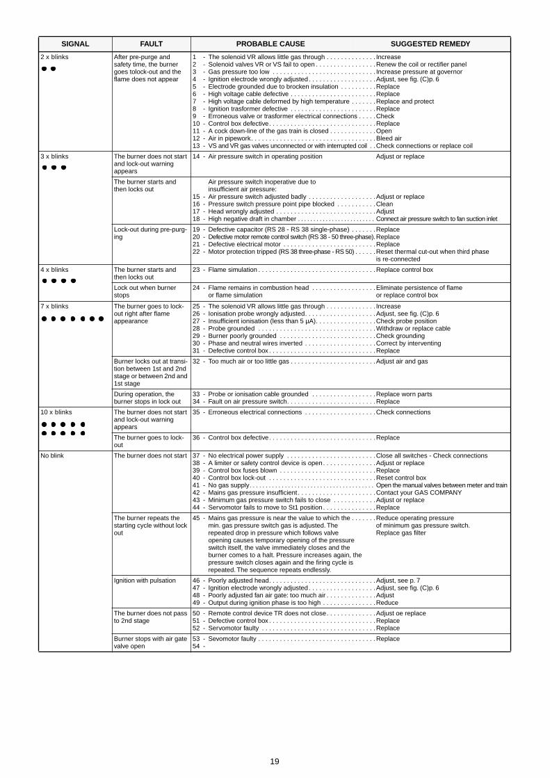
SIGNAL FAULT PROBABLE CAUSE SUGGESTED REMEDY
2 x blinks After pre-purge and safety time, the burner goes tolock-out and the flame does not appear
1 - The solenoid VR allows little gas through . . . . . . . . . . . . . . Increase2 - Solenoid valves VR or VS fail to open . . . . . . . . . . . . . . . . .Renew the coil or rectifier panel3 - Gas pressure too low . . . . . . . . . . . . . . . . . . . . . . . . . . . . . Increase pressure at governor4 - Ignition electrode wrongly adjusted. . . . . . . . . . . . . . . . . . .Adjust, see fig. (C)p. 65 - Electrode grounded due to brocken insulation . . . . . . . . . .Replace6 - High voltage cable defective . . . . . . . . . . . . . . . . . . . . . . . .Replace7 - High voltage cable deformed by high temperature . . . . . . .Replace and protect8 - Ignition trasformer defective . . . . . . . . . . . . . . . . . . . . . . . .Replace9 - Erroneous valve or trasformer electrical connections . . . . .Check10 - Control box defective. . . . . . . . . . . . . . . . . . . . . . . . . . . . . .Replace11 - A cock down-line of the gas train is closed . . . . . . . . . . . . .Open12 - Air in pipework. . . . . . . . . . . . . . . . . . . . . . . . . . . . . . . . . . .Bleed air13 - VS and VR gas valves unconnected or with interrupted coil . .Check connections or replace coil
3 x blinks The burner does not start and lock-out warning appears
14 - Air pressure switch in operating position Adjust or replace
The burner starts and then locks out
Air pressure switch inoperative due toinsufficient air pressure:
15 - Air pressure switch adjusted badly . . . . . . . . . . . . . . . . . . .Adjust or replace16 - Pressure switch pressure point pipe blocked . . . . . . . . . . .Clean17 - Head wrongly adjusted . . . . . . . . . . . . . . . . . . . . . . . . . . . .Adjust18 - High negative draft in chamber . . . . . . . . . . . . . . . . . . . . . . . . . Connect air pressure switch to fan suction inlet
Lock-out during pre-purg-ing
19 - Defective capacitor (RS 28 - RS 38 single-phase) . . . . . . .Replace20 - Defective motor remote control switch (RS 38 - 50 three-phase).Replace21 - Defective electrical motor . . . . . . . . . . . . . . . . . . . . . . . . . .Replace22 - Motor protection tripped (RS 38 three-phase - RS 50) . . . . . .Reset thermal cut-out when third phase
is re-connected
4 x blinks The burner starts and then locks out
23 - Flame simulation . . . . . . . . . . . . . . . . . . . . . . . . . . . . . . . . .Replace control box
Lock out when burner stops
24 - Flame remains in combustion head . . . . . . . . . . . . . . . . . .Eliminate persistence of flame or flame simulation or replace control box
7 x blinks The burner goes to lock-out right after flame appearance
25 - The solenoid VR allows little gas through . . . . . . . . . . . . . . Increase26 - Ionisation probe wrongly adjusted. . . . . . . . . . . . . . . . . . . .Adjust, see fig. (C)p. 627 - Insufficient ionisation (less than 5 µA). . . . . . . . . . . . . . . . .Check probe position28 - Probe grounded . . . . . . . . . . . . . . . . . . . . . . . . . . . . . . . . .Withdraw or replace cable29 - Burner poorly grounded . . . . . . . . . . . . . . . . . . . . . . . . . . .Check grounding30 - Phase and neutral wires inverted . . . . . . . . . . . . . . . . . . . .Correct by interventing31 - Defective control box . . . . . . . . . . . . . . . . . . . . . . . . . . . . . .Replace
Burner locks out at transi-tion between 1st and 2nd stage or between 2nd and 1st stage
32 - Too much air or too little gas . . . . . . . . . . . . . . . . . . . . . . . .Adjust air and gas
During operation, the burner stops in lock out
33 - Probe or ionisation cable grounded . . . . . . . . . . . . . . . . . .Replace worn parts34 - Fault on air pressure switch. . . . . . . . . . . . . . . . . . . . . . . . .Replace
10 x blinks The burner does not start and lock-out warning appears
35 - Erroneous electrical connections . . . . . . . . . . . . . . . . . . . .Check connections
The burner goes to lock-out
36 - Control box defective. . . . . . . . . . . . . . . . . . . . . . . . . . . . . .Replace
No blink The burner does not start 37 - No electrical power supply . . . . . . . . . . . . . . . . . . . . . . . . .Close all switches - Check connections38 - A limiter or safety control device is open. . . . . . . . . . . . . . .Adjust or replace39 - Control box fuses blown . . . . . . . . . . . . . . . . . . . . . . . . . . .Replace40 - Control box lock-out . . . . . . . . . . . . . . . . . . . . . . . . . . . . . .Reset control box41 - No gas supply. . . . . . . . . . . . . . . . . . . . . . . . . . . . . . . . . . . . . . . Open the manual valves between meter and train 42 - Mains gas pressure insufficient . . . . . . . . . . . . . . . . . . . . . .Contact your GAS COMPANY43 - Minimum gas pressure switch fails to close . . . . . . . . . . . .Adjust or replace44 - Servomotor fails to move to St1 position . . . . . . . . . . . . . . .Replace
The burner repeats the starting cycle without lock out
45 - Mains gas pressure is near the value to which the . . . . . . .Reduce operating pressuremin. gas pressure switch gas is adjusted. The of minimum gas pressure switch.repeated drop in pressure which follows valve Replace gas filteropening causes temporary opening of the pressure switch itself, the valve immediately closes and the burner comes to a halt. Pressure increases again, the pressure switch closes again and the firing cycle isrepeated. The sequence repeats endlessly.
Ignition with pulsation 46 - Poorly adjusted head. . . . . . . . . . . . . . . . . . . . . . . . . . . . . .Adjust, see p. 747 - Ignition electrode wrongly adjusted. . . . . . . . . . . . . . . . . . .Adjust, see fig. (C)p. 648 - Poorly adjusted fan air gate: too much air . . . . . . . . . . . . . .Adjust49 - Output during ignition phase is too high . . . . . . . . . . . . . . .Reduce
The burner does not pass to 2nd stage
50 - Remote control device TR does not close. . . . . . . . . . . . . .Adjust oe replace51 - Defective control box . . . . . . . . . . . . . . . . . . . . . . . . . . . . . .Replace52 - Servomotor faulty . . . . . . . . . . . . . . . . . . . . . . . . . . . . . . . .Replace
Burner stops with air gate valve open
53 - Sevomotor faulty . . . . . . . . . . . . . . . . . . . . . . . . . . . . . . . . .Replace54 -
20
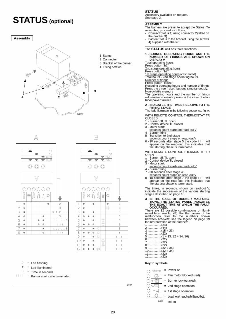
STATUSAccessory available on request. See page 2.
ASSEMBLYThe burners are preset to accept the Status. Toassemble, proceed as follows:- Connect Status 1) using connector 2) fitted on
the bracket 3).- Fasten Status to the bracket using the screws
4) supplied with the kit.
The STATUS unit has three functions:
1 - BURNER OPERATING HOURS AND THENUMBER OF FIRINGS ARE SHOWN ONDISPLAY V
Total operating hoursPress button "h1".2nd stage operating hoursPress button "h2".1st stage operating hours (calculated)Total hours - 2nd stage operating hours.Number of firingsPress button "count".Resetting operating hours and number of firingsPress the three "reset" buttons simultaneously.Non-volatile memoryThe operating hours and the number of firingswill remain in memory even in the case of elec-trical power failures.
2 - INDICATES THE TIMES RELATIVE TO THEFIRING STAGE
The leds illuminate in the following sequence, fig. A:
WITH REMOTE CONTROL THERMOSTAT TRCLOSED:1 - Burner off, TL open2 - Control device TL closed3 - Motor start:
seconds count starts on read-out V4 - Burner firing5 - Transition to 2nd stage
seconds count stops on read-out V6 - 10 seconds after stage 5 the code I I I I will
appear on the read-out: this indicates thatthe starting phase is terminated.
WITH REMOTE CONTROL THERMOSTAT TROPEN1 - Burner off, TL open2 - Control device TL closed3 - Motor start:
seconds count starts on read-out V4 - Burner firing7 - 30 seconds after stage 4:
seconds count stops on read-out V8 - 10 seconds after stage 7 the code I I I I will
appear on the read-out: this indicates thatthe starting phase is terminated.
The times, in seconds, shown on read-out V,indicate the succession of the various startingstages described on page 16.
3 - IN THE CASE OF BURNER MALFUNC-TIONS, THE STATUS PANEL INDICATESTHE EXACT TIME AT WHICH THE FAULTOCCURRED.
There are 12 possible combinations of illumi-nated leds, see fig. (B). For the causes of themalfunction refer to the numbers shownbetween brackets; see the legend on page 19for interpretation of the numbers.1 ................(24)2 ................(44)3 ................(15 ÷ 23)4 ................(22)5 ................(1 ÷ 13, 32 ÷ 34, 36)6 ................(22)7 ................(32)8 ................(22)9 ................(32 ÷ 34)10 ..............(32 ÷ 34)11 ..............(22)12 ..............(22)
Key to symbols:
= Power on
= Fan motor blocked (red)
= Burner lock-out (red)
= 2nd stage operation
= 1st stage operation
= Load level reached (Stand-by),
led: on
STATUS (optional)
Led flashing
Led illuminated
Time in secondsBurner start cycle terminated
D947
Assembly
2
1 Status2 Connector3 Bracket of the burner4 Fixing screws
1
4
3
D3057
D978

RIELLO S.p.A.
Via degli Alpini 1
I - 37045 Legnago (VR)
Tel.: +39.0442.630111 Fax: +39.0442.630375
http:// www.rielloburners.com
Subject to modifications - Sujeto a modificaciones - Sujeito a modificações