
Fusion Splicing Today's Singlemode Fibers.FINAL
16
Fusion Splicing Today’s Singlemode Fibers August, 2007 Superior Essex and OFS have combined field experience and laboratory studies to investigate the realities of fusion splicing singlemode fiber in today’s FTTH environment. This white paper discusses the results and implications of the findings, and provides practical guidelines for network planners and designers as well as splicing contractors and technicians. Superior Essex Inc. | OFS Copyright 2007, All Rights reserved
Transcript of Fusion Splicing Today's Singlemode Fibers.FINAL

8/7/2019 Fusion Splicing Today's Singlemode Fibers.FINAL
http://slidepdf.com/reader/full/fusion-splicing-todays-singlemode-fibersfinal 1/16
Fusion Splicing Today’s Singlemode Fibers
August, 2007
Superior Essex and OFS have combined field experience and laboratory studies to investigatethe realities of fusion splicing singlemode fiber in today’s FTTH environment. This white paper discusses the results and implications of the findings, and provides practical guidelines for network planners and designers as well as splicing contractors and technicians.
Superior Essex Inc. | OFS Copyright 2007, All Rights reserved

8/7/2019 Fusion Splicing Today's Singlemode Fibers.FINAL
http://slidepdf.com/reader/full/fusion-splicing-todays-singlemode-fibersfinal 2/16

8/7/2019 Fusion Splicing Today's Singlemode Fibers.FINAL
http://slidepdf.com/reader/full/fusion-splicing-todays-singlemode-fibersfinal 3/16
Fusion Splicing Today’s Singlemode Fibers
What is splicing?
Splicing is used to permanently join two optical fibers where no additional
changes are expected to be made to those fibers at that juncture. This is in
contrast to connectors, which are designed to allow quick re-configuration of fiber
links.
There are two ways to splice optical fibers: mechanical and fusion. In a
mechanical splice, the fibers are held together with ends touching inside some
type of sleeve. Mechanical splices are typically used for semi-permanent
connections, as in an emergency restoration or for testing and troubleshooting.
Mechanical splices usually exhibit greater loss and reflection than fusion splices.
In fusion splicing, the two fibers are literally welded, or fused together. This
makes for a strong joint that exhibits very low loss and virtually no reflection.
This paper focuses on fusion splicing, although much of what is discussed here
can also be applied to mechanical splicing.
Fusion Splicers
Fusion splicing is performed with a piece of equipment called a fusion splicer.
The fiber ends are prepared and cleaved, placed in alignment fixtures on the
fusion splicer, and at the press of a button the fiber ends are heated with
electrodes, brought together, and fused.
There are many models of fusion splicers available, varying in features and
capability, and of course cost. High-end units allow users to store separate
programs or recipes where factors such as splice time and temperature can be
Superior Essex Inc. | OFS Copyright 2007, All Rights Reserved 3

8/7/2019 Fusion Splicing Today's Singlemode Fibers.FINAL
http://slidepdf.com/reader/full/fusion-splicing-todays-singlemode-fibersfinal 4/16
Fusion Splicing Today’s Singlemode Fibers
highly customized. Such units magnify and visually display the splice, and use
active core alignment to line up the fibers. Light injection technology and imaging
software line up the cores so maximum light passes from one fiber to the other,
ensuring minimal splice loss. Such splicing units can also provide an estimate of
the splice loss.
More basic fusion splicers may employ clad alignment to line up the fibers for
splicing. The fibers sit in a holder or V-groove, and are lined up “physically”,
based on the outer diameter of the fiber’s cladding. These splicing units are at
the mercy of the fibers’ glass geometry characteristics and tolerances (Clad
Diameter, Clad Non-Circularity, and Core-to-Clad Concentricity). Just because
the outer diameters are aligned, doesn’t mean the cores will be perfectly aligned.
Such units typically produce higher loss splices and lack the features and
flexibility of higher end splicers.
Fusion Splice Process Capability
The fiber parameters that most affect splice loss in singlemode fiber are Mode
Field Diameter (MFD – the diameter of the light-carrying region of the fiber) and
Core-Clad Concentricity.
Estimated loss from mismatches in MFD can be calculated from the following
equation:
Loss (dB) = 20 x LOG10 [(2 x MFD1 x MFD2) / (MFD1
2
+ MFD2
2
)]
Today’s typical MFD specification for type G.652 singlemode fiber is 9.2 ± 0.4 µm
at 1310 nm. Even at the opposite extremes of this spec, losses due to MFD
mismatch should be ≤0.033 dB (Note that the ITU-T G.652 spec actually allows a
Superior Essex Inc. | OFS Copyright 2007, All Rights Reserved 4

8/7/2019 Fusion Splicing Today's Singlemode Fibers.FINAL
http://slidepdf.com/reader/full/fusion-splicing-todays-singlemode-fibersfinal 5/16
Fusion Splicing Today’s Singlemode Fibers
deviation in MFD of 7.9 to 10.2 µm, resulting in a potential splice loss of 0.3 dB.)
If unlike fibers with differing MFD’s are spliced, for example G.655 NZDF, or the
new generation of G.657 bend insensitive fibers, the splice losses will likely be
higher than when splicing like fibers. However, even these cases should be
manageable with proper system design and practical splice specifications.
Core-Clad Concentricity Error, or the amount that the core is off-center from the
cladding, can also contribute significantly to splice loss in singlemode fiber. The
following graph shows how much loss there could be for a given amount of offset
between the cores of spliced fibers.
Relationship between Splice Loss and Offset Between Cores
The typical specification for Core-Clad Concentricity in today’s G.652 singlemode
fibers is ≤ 0.5 µm. If two fibers, each with this much core offset, are spliced such
that the offset is in opposite directions (total 1 µm offset), 0.056 dB loss could be
expected.
Between MFD mismatch and core offset, maximum potential splice loss should
be ≤ 0.089 (0.033 + 0.056) dB. However, this only represents intrinsic loss due to
fiber geometry and does not account for any additional loss introduced by the
Superior Essex Inc. | OFS Copyright 2007, All Rights Reserved 5

8/7/2019 Fusion Splicing Today's Singlemode Fibers.FINAL
http://slidepdf.com/reader/full/fusion-splicing-todays-singlemode-fibersfinal 6/16
Fusion Splicing Today’s Singlemode Fibers
splice equipment, operator, or the environment. It may be rare that the extremes
of each spec are encountered in the field, but a recent splice study performed by
OFS on G.652 singlemode fiber (OFS to OFS, and OFS to competitor) did yield
some splices that had losses of 0.1 dB or higher. Average splice loss of all
samples was quite low at 0.02 dB, but there were instances where losses
exceeded 0.1 dB.
Splice Loss Study
As the graph shows, the vast majority of splices were below 0.05 dB, but there
were several above that, as well as a few above 0.10 dB.
It should also be noted that splice studies performed in a lab, like those
referenced here, are usually done in ideal and relaxed conditions with state-of-
the-art, well-maintained splicing equipment and cleavers. In reality, splicing is
often done in haste, and in less than ideal conditions (cold, windy, dusty/dirty…)with equipment that may be well used and not performing at its very best. Losses
even greater than those seen in the splice studies here can be expected in field
conditions.
Superior Essex Inc. | OFS Copyright 2007, All Rights Reserved 6
8/7/2019 Fusion Splicing Today's Singlemode Fibers.FINAL
http://slidepdf.com/reader/full/fusion-splicing-todays-singlemode-fibersfinal 7/16
Fusion Splicing Today’s Singlemode Fibers
Measuring Splice Loss
Once a splice has been made, it often needs to be measured to see how much
loss occurs at that joint. There are several techniques and approaches to doing
this. Which method, or combination of methods, is used will depend on variousfactors, including the design, purpose, and critical nature of the network, as well
as any industry specifications or standards that may govern such.
There are three basic ways to obtain a splice loss reading. The three methods
are detailed here, along with their advantages and limitations.
1) Fusion splicer estimated loss.
Immediately after completing a splice, many fusion splicers display an
estimate of the splice loss. This can give you a quick indication of the general
quality of the splice, but it is exactly that – an estimate . Caution and prudence
is urged in relying on estimated splice loss to determine whether a splice is
acceptable. There are no standards governing splice loss measurements by a
fusion splicer, and no means of calibration, so the accuracy of such
measurements can vary widely.
A fusion splicer’s estimated splice loss reading is most often used to
determine whether or not to immediately remake a splice. If the reading is
high, an immediate remake may be prudent. Where to set this re-splice
criterion depends on the splicer, the fibers, the technician, and environmental
factors (temperature & humidity, wind, dust, etc.). The most thorough method
is to perform a splicing trial where a dozen or more splices are performed and
measured by other means (as indicated below) and compared to the splicer’s
estimated readings. This provides a correlation between the splicer’s estimate
and the actual results. This trial may need to be repeated periodically,
especially if there’s a change in fiber type / manufacturer, technician, or
environment. If such a trial is not prudent, the remake criterion should at a
minimum be set at the mean splice loss specification for the job. Setting it any
Superior Essex Inc. | OFS Copyright 2007, All Rights Reserved 7

8/7/2019 Fusion Splicing Today's Singlemode Fibers.FINAL
http://slidepdf.com/reader/full/fusion-splicing-todays-singlemode-fibersfinal 8/16
Fusion Splicing Today’s Singlemode Fibers
lower will likely result in rework without really knowing if the rework is
necessary.
2) OLTS (Optical Loss Test Set, also known as a Source and Power Meter).
A traditional source and power meter can be used to estimate splice loss on a
relatively short link containing one splice. This is still somewhat of an
estimate, since an OLTS measures the loss over the entire link, which would
include the fiber as well as the splice. In a relatively short link, the loss due to
just the fiber itself should be quite small, so the power meter reading would be
close to, or just slightly higher than, the actual loss of the splice. If the
attenuation of the cable is known, it can be subtracted from the power meter
reading to get a closer estimate of the splice loss.
On longer links, more of the overall loss will be attributed to the fiber itself,
making it more difficult and less accurate to estimate the loss of a splice.
Also, keep in mind that if there are multiple splices in a link, an OLTS will only
report the total loss of all the splices. It cannot distinguish between individual
splices. Only the average loss of each splice can be determined.
OLTS’s are an economical and useful way to make sure a link meets a power
budget requirement, which of course is the number one criterion. Even if there
are splices in a link that might be considered “high” (high splice loss), it does
not matter as long as the overall link meets the link loss requirement. Splices
won’t get worse over time (assuming it was fused properly) and link budgets
usually have a safety factor built in for environmental and aging
considerations, so a high loss splice in a link that meets its loss budget should
not be of concern.
Superior Essex Inc. | OFS Copyright 2007, All Rights Reserved 8

8/7/2019 Fusion Splicing Today's Singlemode Fibers.FINAL
http://slidepdf.com/reader/full/fusion-splicing-todays-singlemode-fibersfinal 9/16
Fusion Splicing Today’s Singlemode Fibers
OTDR (Optical Time Domain Reflectometer) An OTDR is a specialized test
instrument for optical fiber. It is a very useful tool in that it provides a
representative picture of the fiber and only requires access to one end of the
fiber. An OTDR is the only means of obtaining a truly accurate splice loss
measurement. Still, a good understanding of how an OTDR works – and its
limitations – is necessary in order to avoid confusion or debate in determining
whether splice loss requirements are met, and to prevent any unnecessary
rework or delay.
An OTDR uses back-scattered, or reflected, light to measure loss over distance.
The OTDR shoots pulses of light into the fiber and measures how much light is
reflected back and how long it takes to travel back. It displays the measurements
in a graph known as a trace which is simply signal power versus distance. The
trace displays how much loss there is anywhere along the length of a fiber, or
along a link that includes connections and splices.
Typical OTDR Trace
Superior Essex Inc. | OFS Copyright 2007, All Rights Reserved 9
8/7/2019 Fusion Splicing Today's Singlemode Fibers.FINAL
http://slidepdf.com/reader/full/fusion-splicing-todays-singlemode-fibersfinal 10/16
Fusion Splicing Today’s Singlemode Fibers
Since an OTDR measures reflected light, it is actually an indirect measurement
and is therefore only an estimate of the power loss in a fiber. A direct
measurement method, such as the OLTS described above, is more accurate for total end-to-end loss measurement, but does not provide the picture and single-
end testing.
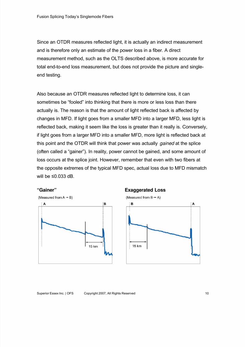
Also because an OTDR measures reflected light to determine loss, it can
sometimes be “fooled” into thinking that there is more or less loss than there
actually is. The reason is that the amount of light reflected back is affected by
changes in MFD. If light goes from a smaller MFD into a larger MFD, less light is
reflected back, making it seem like the loss is greater than it really is. Conversely,
if light goes from a larger MFD into a smaller MFD, more light is reflected back at
this point and the OTDR will think that power was actually gained at the splice
(often called a “gainer”). In reality, power cannot be gained, and some amount of
loss occurs at the splice joint. However, remember that even with two fibers at
the opposite extremes of the typical MFD spec, actual loss due to MFD mismatch
will be ≤0.033 dB. “Gainer” Exaggerated Loss
Superior Essex Inc. | OFS Copyright 2007, All Rights Reserved 10

8/7/2019 Fusion Splicing Today's Singlemode Fibers.FINAL
http://slidepdf.com/reader/full/fusion-splicing-todays-singlemode-fibersfinal 11/16
Fusion Splicing Today’s Singlemode Fibers
Mode field mismatch often happens when fibers from different manufacturers, or
different types of fibers, are spliced together. This is due to differences in MFD
among fiber types and manufacturers. However, mode field mismatch can also
occur when splicing the same fiber type from the same manufacturer. This can
happen simply due to the manufacturing tolerances of the fiber. World class fiber
manufacturers have narrowed the tolerance for MFD to ±0.4µm at 1310nm and
±0.8µm at 1550nm. However, even these microscopic differences will show up
on an OTDR if one fiber is on the upper side of the tolerance and the other is on
the lower.
The important point to remember is that the gainer is “apparent” and the loss is“exaggerated”. So how do we determine the correct splice loss?
Importance of bidirectional measurement.
The industry recognizes that the most accurate measurement of actual splice
loss is the average of a 2-way (bidirectional) test. This is documented in industry
standard ANSI/TIA/EIA-455-8-2000 Measurement of Splice or Connector Loss
and Reflectance using an OTDR .
Splice Loss = Average of measurements from both directions
For example:
Measurement 1 – CO to Field – Splice loss: 0.18 dB
Measurement 2 – Field to CO – Splice loss: -0.14 dB (gainer)
Sum: 0.04 dB
True Splice Loss Average: 0.02 dB – bidirectional average
Superior Essex Inc. | OFS Copyright 2007, All Rights Reserved 11
8/7/2019 Fusion Splicing Today's Singlemode Fibers.FINAL
http://slidepdf.com/reader/full/fusion-splicing-todays-singlemode-fibersfinal 12/16
Fusion Splicing Today’s Singlemode Fibers
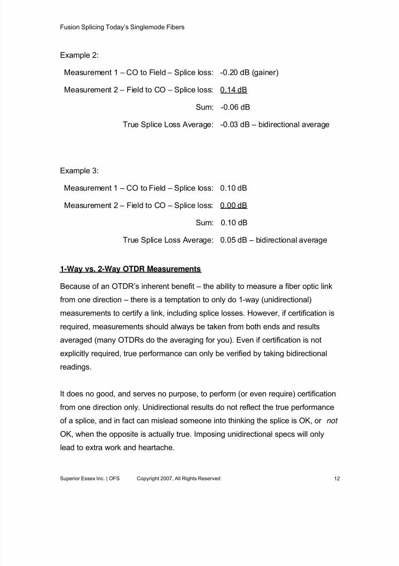
Example 2:
Measurement 1 – CO to Field – Splice loss: -0.20 dB (gainer)
Measurement 2 – Field to CO – Splice loss: 0.14 dB
Sum: -0.06 dB
True Splice Loss Average: -0.03 dB – bidirectional average
Example 3:
Measurement 1 – CO to Field – Splice loss: 0.10 dB
Measurement 2 – Field to CO – Splice loss: 0.00 dB
Sum: 0.10 dB
True Splice Loss Average: 0.05 dB – bidirectional average
1-Way vs. 2-Way OTDR Measurements
Because of an OTDR’s inherent benefit – the ability to measure a fiber optic link
from one direction – there is a temptation to only do 1-way (unidirectional)
measurements to certify a link, including splice losses. However, if certification is
required, measurements should always be taken from both ends and results
averaged (many OTDRs do the averaging for you). Even if certification is not
explicitly required, true performance can only be verified by taking bidirectional
readings.
It does no good, and serves no purpose, to perform (or even require) certificationfrom one direction only. Unidirectional results do not reflect the true performance
of a splice, and in fact can mislead someone into thinking the splice is OK, or not
OK, when the opposite is actually true. Imposing unidirectional specs will only
lead to extra work and heartache.
Superior Essex Inc. | OFS Copyright 2007, All Rights Reserved 12

8/7/2019 Fusion Splicing Today's Singlemode Fibers.FINAL
http://slidepdf.com/reader/full/fusion-splicing-todays-singlemode-fibersfinal 13/16
Fusion Splicing Today’s Singlemode Fibers
Unidirectional OTDR measurements are useful for troubleshooting, or for 1st-pass
assessment of splices in order to decide if any should be remade before going to
the other end of the link to take measurements from the other direction. As long
as a reasonable and moderate limit is put in place on unidirectional loss (see
section on Splice Loss Specifications), this can save time. The few splices that
might read high can be remade. But the majority that read fine or even “a little
high” will in all likelihood be fine when measured at the other end and
bidirectional results are averaged.
Splice Loss Specifications
Splice loss specs are intended to ensure that the overall link loss is within
budget. System performance is dependent on overall link loss, not individual
splices. For example, if the loss budget on a link is 8 dB (after safety margin),
and the attenuation in the cable only contributes 4.8 dB (e.g. 0.4 dB/km over a
link of 12 kms is 4.8 dB), then 3.2 dB is available for total splice loss. Typically,
some splices will be on the higher side, but these will be offset by splices on the
lower side. As long as they all add up to no more than 3.2 dB, there won’t be a
problem.
Imposing a stringent splice loss spec on all splices in a link may be counter-
productive. In general, a reasonable splice loss spec should be established
based on the design of the link and should be an average of all splices. Is there a
stringent power budget? Then perhaps the splice loss spec should be ≤ 0.1 dB
average. Is there plenty of power budget? Then a spec of ≤ 0.25 dB average
might be completely sufficient. If individual splice loss limits are imposed, keep in
mind that due to fiber geometry variation, equipment, environmental conditions,
technician expertise, etc., some individual splices may not meet the spec no
matter what. There should be some allowance for such. One splice that may not
quite meet the spec will certainly be offset by several other splices that are well
within the spec.
Superior Essex Inc. | OFS Copyright 2007, All Rights Reserved 13

8/7/2019 Fusion Splicing Today's Singlemode Fibers.FINAL
http://slidepdf.com/reader/full/fusion-splicing-todays-singlemode-fibersfinal 14/16
Fusion Splicing Today’s Singlemode Fibers
Avoid setting a unidirectional splice loss specification. Unidirectional
measurements are only useful as guidance and have no real bearing on the
actual performance of the splice. If unidirectional measurements are used at all, it
should be done with some knowledge of the fiber being spliced, along with the
capability of the equipment being used. If a unidirectional limit is too tight, it will
cause many unnecessary remakes.
One strategy that can be useful in the field is to set a unidirectional threshold of
0.3 dB or higher, which would trigger a remake. If after two tries, the one-way
measurement does not come down, a mode-field mismatch is very likely. The
splice should be measured from the other direction to determine its true loss
before spending more time on remakes.
Guidelines for Network Planners and Designers
Industry specifications vary somewhat in the allowable loss for splices, but agree
on two major points:
1) Splice loss is based on a bidirectional average OTDR measurement
2) Splice loss specification is based on the mean splice loss of all splices.
To ensure the end result of a high-performance network at the lowest installed
cost, Network planners and designers should:
1) Set splice loss specifications based on the overall requirements of the link
2) Set splice loss specifications based on the mean splice loss of all splices
3) Specify bidirectional average OTDR measurement for splice loss
measurement4) Avoid specifying unidirectional OTDR splice loss requirements
Superior Essex Inc. | OFS Copyright 2007, All Rights Reserved 14

8/7/2019 Fusion Splicing Today's Singlemode Fibers.FINAL
http://slidepdf.com/reader/full/fusion-splicing-todays-singlemode-fibersfinal 15/16
Fusion Splicing Today’s Singlemode Fibers
Guidelines for Splicing Contractors and Technicians
Many advances have been made in optical fiber and the equipment used to
splice it, but fusion splicing remains a technical skill that can be affected by many
different factors. To ensure quality, efficient fusion splices with minimal rework,
splicing contractors and technicians should consider the following guidelines:
In General:
1) Follow the applicable equipment manufacturer’s guidelines for setup and
maintenance of all splice equipment.
2) Maintain clean equipment and a clean splice environment, being
especially wary of windy and/or dusty conditions.
Splice Loss:
1) Use the fusion splicer’s estimated splice loss reading as an initial go/no-go
evaluation of the splice.
a. Establish the limit at the same dB value as the mean splice loss
value in the job specification.
b. If the initial splice does not fall within the limit, repeat the splice no
more than two more times without performing a bidirectional OTDR
average to validate the finding.
2) If using unidirectional OTDR testing to qualify splices:
a. Do not break and re-splice gainers. They typically will not change
significantly.
b. Set a generous threshold for remake.
c. Do not break and remake excessive losses more than once without
performing a bidirectional OTDR average to validate the finding.
Superior Essex Inc. | OFS Copyright 2007, All Rights Reserved 15
8/7/2019 Fusion Splicing Today's Singlemode Fibers.FINAL
http://slidepdf.com/reader/full/fusion-splicing-todays-singlemode-fibersfinal 16/16
Fusion Splicing Today’s Singlemode Fibers
Superior Essex Inc. | OFS Copyright 2007, All Rights Reserved 16
Conclusion
Fusion splice loss is affected by many factors, some of which can be controlled
or manipulated by splice technicians and some of which cannot. Variations in
glass geometry (MFD, core-clad concentricity) between fiber types, fiber manufacturers, and even within the tolerances of the same fiber type, can result
in true splice losses exceeding 0.1 dB, and unidirectional measurements
(gainers, or exaggerated losers) even higher.
An OTDR is the best device to use for measuring splice loss, with the true loss
being the average of bidirectional measurements. Unidirectional measurements
can be misleading, sometimes showing a gain in power (“gainers”) or
exaggerated loss. This is due to natural variations in MFD between spliced fibers
and the way the OTDR measures the backscattered light at these joints.
With the increasing amount of optical fiber being fusion spliced in today’s
broadband and access networks, it is important to have a good understanding of
the factors that affect splice loss, as well as the various measurement aspects
surrounding splice loss verification. Splice loss specifications should be set with
the total link power budget in mind and be based on average splice loss. This will
ensure that an installation has realistic splice loss requirements and that the
power budget can be met with confidence while minimizing the time and expense
associated with splice remakes.
Tim West, RCDDManager – Applications EngineeringSUPERIOR ESSEX
Communications Cable Segment6120 Powers Ferry Road, Suite 150Atlanta, GA 30339770-657-6000
Tony IrujoMgr. Customer Tech Supportofs
Optical Fiber Division50 Hall Rd.Sturbridge, MA 01566508-347-8590