Foxy R1 and Foxy R2 Fraction Collectors - - Homepage of
122
Foxy R1 and Foxy R2 Fraction Collectors Foxy R1 Foxy R2 Part #69-2133-667 of Assembly #60-2133-665 Copyright © 2008. All rights reserved, Teledyne Isco, Inc. Revision A: March 31, 2009
Transcript of Foxy R1 and Foxy R2 Fraction Collectors - - Homepage of

Foxy R1 and Foxy R2Fraction Collectors
Foxy R1
Foxy R2
Part #69-2133-667 of Assembly #60-2133-665Copyright © 2008. All rights reserved, Teledyne Isco, Inc.Revision A: March 31, 2009


Foreword
This instruction manual is designed to help you gain a thorough understanding of theoperation of the equipment. Teledyne Isco recommends that you read this manualcompletely before placing the equipment in service.
Although Teledyne Isco designs reliability into all equipment, there is always the possi-bility of a malfunction. This manual may help in diagnosing and repairing the malfunc-tion.
If the problem persists, call or e-mail the Teledyne Isco Technical Service Departmentfor assistance. Simple difficulties can often be diagnosed over the phone.
If it is necessary to return the equipment to the factory for service, please follow theshipping instructions provided by the Customer Service Department, including theuse of the Return Authorization Number specified. Be sure to include a notedescribing the malfunction. This will aid in the prompt repair and return of theequipment.
Teledyne Isco welcomes suggestions that would improve the information presented inthis manual or enhance the operation of the equipment itself.
Teledyne Isco is continually improving its products and reserves the right tochange product specifications, replacement parts, schematics, and instruc-tions without notice.
Contact Information
Customer Service
Phone: (800) 228-4373 (USA, Canada, Mexico)
(402) 464-0231 (Outside North America)
Fax: (402) 465-3022
Email: [email protected]
Technical Support
Phone: (800) 775-2965 (Analytical)
(866) 298-6174 (Samplers and Flow Meters)
Email: [email protected]
Return equipment to: 4700 Superior Street, Lincoln, NE 68504-1398
Other Correspondence
Mail to: P.O. Box 82531, Lincoln, NE 68501-2531
Email: [email protected]
Web site: www.isco.com
Revised March 17, 2009


iii
Foxy® R1 and Foxy® R2 Fraction Collectors
Table of Contents
Section 1 Introduction
1.1 Collection Schemes . . . . . . . . . . . . . . . . . . . . . . . . . . . . . . . . . . . . . . . . . . . . . . . . . . 1-21.2 Racks and Vessels . . . . . . . . . . . . . . . . . . . . . . . . . . . . . . . . . . . . . . . . . . . . . . . . . . . 1-31.3 Features . . . . . . . . . . . . . . . . . . . . . . . . . . . . . . . . . . . . . . . . . . . . . . . . . . . . . . . . . . . 1-41.4 Technical Specifications . . . . . . . . . . . . . . . . . . . . . . . . . . . . . . . . . . . . . . . . . . . . . . 1-51.5 Rear Panel Connectors . . . . . . . . . . . . . . . . . . . . . . . . . . . . . . . . . . . . . . . . . . . . . . . 1-71.6 Accessory Cable Specifications . . . . . . . . . . . . . . . . . . . . . . . . . . . . . . . . . . . . . . . . . 1-9
1.6.1 Cables for Isco Accessories . . . . . . . . . . . . . . . . . . . . . . . . . . . . . . . . . . . . . . 1-91.6.2 Cable for non-Isco Pumps . . . . . . . . . . . . . . . . . . . . . . . . . . . . . . . . . . . . . . . 1-91.6.3 Cable for non-Isco Detectors . . . . . . . . . . . . . . . . . . . . . . . . . . . . . . . . . . . . 1-10
Section 2 Preparation for Use
2.1 Preliminary Checkout . . . . . . . . . . . . . . . . . . . . . . . . . . . . . . . . . . . . . . . . . . . . . . . . 2-12.2 Fluid Connections . . . . . . . . . . . . . . . . . . . . . . . . . . . . . . . . . . . . . . . . . . . . . . . . . . . 2-5
2.2.1 Diverter Valve Connections . . . . . . . . . . . . . . . . . . . . . . . . . . . . . . . . . . . . . 2-52.2.2 Drip Tray Drain Connection . . . . . . . . . . . . . . . . . . . . . . . . . . . . . . . . . . . . . 2-7
2.3 Rack Installation . . . . . . . . . . . . . . . . . . . . . . . . . . . . . . . . . . . . . . . . . . . . . . . . . . . . 2-82.4 Diverter Valve Adjustment. . . . . . . . . . . . . . . . . . . . . . . . . . . . . . . . . . . . . . . . . . . 2-102.5 Installation Qualification Checklist . . . . . . . . . . . . . . . . . . . . . . . . . . . . . . . . . . . . 2-11
Section 3 Programming
3.1 Main Menu . . . . . . . . . . . . . . . . . . . . . . . . . . . . . . . . . . . . . . . . . . . . . . . . . . . . . . . . 3-13.2 Configuration Settings . . . . . . . . . . . . . . . . . . . . . . . . . . . . . . . . . . . . . . . . . . . . . . . 3-2
3.2.1 Rack Settings . . . . . . . . . . . . . . . . . . . . . . . . . . . . . . . . . . . . . . . . . . . . . . . . . 3-33.2.2 RS-232 Serial Settings . . . . . . . . . . . . . . . . . . . . . . . . . . . . . . . . . . . . . . . . . . 3-53.2.3 TCP/IP Settings . . . . . . . . . . . . . . . . . . . . . . . . . . . . . . . . . . . . . . . . . . . . . . . 3-53.2.4 Inject Options . . . . . . . . . . . . . . . . . . . . . . . . . . . . . . . . . . . . . . . . . . . . . . . . . 3-63.2.5 Pump Control Settings . . . . . . . . . . . . . . . . . . . . . . . . . . . . . . . . . . . . . . . . . 3-93.2.6 Analog Peak Settings . . . . . . . . . . . . . . . . . . . . . . . . . . . . . . . . . . . . . . . . . . . 3-93.2.7 Fraction Collector Information . . . . . . . . . . . . . . . . . . . . . . . . . . . . . . . . . . . 3-9
3.3 Method Settings . . . . . . . . . . . . . . . . . . . . . . . . . . . . . . . . . . . . . . . . . . . . . . . . . . . 3-103.3.1 Method Selection . . . . . . . . . . . . . . . . . . . . . . . . . . . . . . . . . . . . . . . . . . . . . 3-103.3.2 Drop Counts . . . . . . . . . . . . . . . . . . . . . . . . . . . . . . . . . . . . . . . . . . . . . . . . . 3-113.3.3 Time Intervals . . . . . . . . . . . . . . . . . . . . . . . . . . . . . . . . . . . . . . . . . . . . . . . 3-133.3.4 Volume . . . . . . . . . . . . . . . . . . . . . . . . . . . . . . . . . . . . . . . . . . . . . . . . . . . . . 3-143.3.5 Threshold Detection . . . . . . . . . . . . . . . . . . . . . . . . . . . . . . . . . . . . . . . . . . . 3-153.3.6 Peak Width Detection . . . . . . . . . . . . . . . . . . . . . . . . . . . . . . . . . . . . . . . . . 3-173.3.7 Time Window . . . . . . . . . . . . . . . . . . . . . . . . . . . . . . . . . . . . . . . . . . . . . . . . 3-20

Foxy® R1 and Foxy® R2 Fraction CollectorsTable of Contents
iv
Section 4 Serial Command Control
4.1 Introduction . . . . . . . . . . . . . . . . . . . . . . . . . . . . . . . . . . . . . . . . . . . . . . . . . . . . . . . . 4-14.2 RS-232 Communication Information . . . . . . . . . . . . . . . . . . . . . . . . . . . . . . . . . . . . 4-14.3 Ethernet Communication Information . . . . . . . . . . . . . . . . . . . . . . . . . . . . . . . . . . 4-14.4 General Command Information . . . . . . . . . . . . . . . . . . . . . . . . . . . . . . . . . . . . . . . . 4-1
4.4.1 Character Format . . . . . . . . . . . . . . . . . . . . . . . . . . . . . . . . . . . . . . . . . . . . . 4-14.4.2 Command Syntax . . . . . . . . . . . . . . . . . . . . . . . . . . . . . . . . . . . . . . . . . . . . . . 4-24.4.3 Line Syntax . . . . . . . . . . . . . . . . . . . . . . . . . . . . . . . . . . . . . . . . . . . . . . . . . . 4-24.4.4 Modes . . . . . . . . . . . . . . . . . . . . . . . . . . . . . . . . . . . . . . . . . . . . . . . . . . . . . . . 4-24.4.5 Errors . . . . . . . . . . . . . . . . . . . . . . . . . . . . . . . . . . . . . . . . . . . . . . . . . . . . . . . 4-24.4.6 Timing . . . . . . . . . . . . . . . . . . . . . . . . . . . . . . . . . . . . . . . . . . . . . . . . . . . . . . 4-2
4.5 Serial Commands . . . . . . . . . . . . . . . . . . . . . . . . . . . . . . . . . . . . . . . . . . . . . . . . . . . 4-24.5.1 Miscellaneous Commands . . . . . . . . . . . . . . . . . . . . . . . . . . . . . . . . . . . . . . . 4-24.5.2 Immediate Control Commands . . . . . . . . . . . . . . . . . . . . . . . . . . . . . . . . . . . 4-64.5.3 Programming Commands . . . . . . . . . . . . . . . . . . . . . . . . . . . . . . . . . . . . . . . 4-94.5.4 Problem Responses . . . . . . . . . . . . . . . . . . . . . . . . . . . . . . . . . . . . . . . . . . . 4-17
Section 5 Maintenance
5.1 Introduction . . . . . . . . . . . . . . . . . . . . . . . . . . . . . . . . . . . . . . . . . . . . . . . . . . . . . . . . 5-15.2 Maintenance . . . . . . . . . . . . . . . . . . . . . . . . . . . . . . . . . . . . . . . . . . . . . . . . . . . . . . . 5-1
5.2.1 Tubing Inspection . . . . . . . . . . . . . . . . . . . . . . . . . . . . . . . . . . . . . . . . . . . . . 5-15.2.2 Collection Rack and Drip Tray Cleaning . . . . . . . . . . . . . . . . . . . . . . . . . . . 5-25.2.3 Exterior Cleaning . . . . . . . . . . . . . . . . . . . . . . . . . . . . . . . . . . . . . . . . . . . . . . 5-25.2.4 Fluid Path Cleaning . . . . . . . . . . . . . . . . . . . . . . . . . . . . . . . . . . . . . . . . . . . 5-25.2.5 Drop Counter Cleaning . . . . . . . . . . . . . . . . . . . . . . . . . . . . . . . . . . . . . . . . . 5-3
5.3 Service . . . . . . . . . . . . . . . . . . . . . . . . . . . . . . . . . . . . . . . . . . . . . . . . . . . . . . . . . . . . 5-45.4 Instrument Returns . . . . . . . . . . . . . . . . . . . . . . . . . . . . . . . . . . . . . . . . . . . . . . . . . 5-4
5.4.1 How to Ship Returns . . . . . . . . . . . . . . . . . . . . . . . . . . . . . . . . . . . . . . . . . . . 5-4
Appendix A Icon Glossary and Menu Charts
A.1 Touch Screen Icon Glossary . . . . . . . . . . . . . . . . . . . . . . . . . . . . . . . . . . . . . . . . . . . A-1A.2 Touch Screen Menu Flow Charts. . . . . . . . . . . . . . . . . . . . . . . . . . . . . . . . . . . . . . . A-6
Appendix B Replacement Parts Listings

Foxy® R1 and Foxy® R2 Fraction CollectorsTable of Contents
v
List of Figures1-1 Foxy R1 (left) and Foxy R2 (right) fraction collectors . . . . . . . . . . . . . . . . . . . . . . 1-11-2 Fraction collector features . . . . . . . . . . . . . . . . . . . . . . . . . . . . . . . . . . . . . . . . . . . . 1-52-1 Adjusting the diverter valve height . . . . . . . . . . . . . . . . . . . . . . . . . . . . . . . . . . . . 2-22-2 Main menu . . . . . . . . . . . . . . . . . . . . . . . . . . . . . . . . . . . . . . . . . . . . . . . . . . . . . . . . 2-32-3 Method Select screen . . . . . . . . . . . . . . . . . . . . . . . . . . . . . . . . . . . . . . . . . . . . . . . . 2-32-4 Edit Method Settings screen . . . . . . . . . . . . . . . . . . . . . . . . . . . . . . . . . . . . . . . . . . 2-42-5 Time-based Fractions screen . . . . . . . . . . . . . . . . . . . . . . . . . . . . . . . . . . . . . . . . . . 2-42-6 Diverter valve ports. . . . . . . . . . . . . . . . . . . . . . . . . . . . . . . . . . . . . . . . . . . . . . . . . 2-52-7 Tubing preparation . . . . . . . . . . . . . . . . . . . . . . . . . . . . . . . . . . . . . . . . . . . . . . . . . 2-62-8 Connections to valve . . . . . . . . . . . . . . . . . . . . . . . . . . . . . . . . . . . . . . . . . . . . . . . . 2-72-9 Rack guide pins and bottle location ridges . . . . . . . . . . . . . . . . . . . . . . . . . . . . . . . 2-82-10 Rack installed with ground post touching guide pin . . . . . . . . . . . . . . . . . . . . . . 2-92-11 Diverter Valve adjusted with 1/2 inch or 1 cm clearance . . . . . . . . . . . . . . . . . . 2-103-1 Main Menu . . . . . . . . . . . . . . . . . . . . . . . . . . . . . . . . . . . . . . . . . . . . . . . . . . . . . . . . 3-13-2 Configuration Tools Menu . . . . . . . . . . . . . . . . . . . . . . . . . . . . . . . . . . . . . . . . . . . . 3-33-3 Rack options menu . . . . . . . . . . . . . . . . . . . . . . . . . . . . . . . . . . . . . . . . . . . . . . . . . . 3-33-4 Inject options timing diagram . . . . . . . . . . . . . . . . . . . . . . . . . . . . . . . . . . . . . . . . . 3-63-5 Timed options timing diagram . . . . . . . . . . . . . . . . . . . . . . . . . . . . . . . . . . . . . . . . 3-73-6 Overlay, Next and Skip options diagram . . . . . . . . . . . . . . . . . . . . . . . . . . . . . . . . 3-83-7 Method Settings Menu . . . . . . . . . . . . . . . . . . . . . . . . . . . . . . . . . . . . . . . . . . . . . . 3-103-8 Method Selection Menu . . . . . . . . . . . . . . . . . . . . . . . . . . . . . . . . . . . . . . . . . . . . . 3-103-9 Rename Method display . . . . . . . . . . . . . . . . . . . . . . . . . . . . . . . . . . . . . . . . . . . . . 3-113-10 Drop Counts display . . . . . . . . . . . . . . . . . . . . . . . . . . . . . . . . . . . . . . . . . . . . . . . 3-113-11 Time Intervals display . . . . . . . . . . . . . . . . . . . . . . . . . . . . . . . . . . . . . . . . . . . . . 3-133-12 Volume display . . . . . . . . . . . . . . . . . . . . . . . . . . . . . . . . . . . . . . . . . . . . . . . . . . . 3-143-13 Threshold detection cuts peaks when external peak signal
exceeds set percentage . . . . . . . . . . . . . . . . . . . . . . . . . . . . . . . . . . . . . . . . . . . . . . 3-153-14 Threshold Settings menu . . . . . . . . . . . . . . . . . . . . . . . . . . . . . . . . . . . . . . . . . . . 3-163-15 Peak Width detection cuts peaks when internal slope algorithms
indicate a peak . . . . . . . . . . . . . . . . . . . . . . . . . . . . . . . . . . . . . . . . . . . . . . . . . . . . 3-173-16 Peak Width Settings menu . . . . . . . . . . . . . . . . . . . . . . . . . . . . . . . . . . . . . . . . . 3-173-17 A Time Window limits the collection to the defined window . . . . . . . . . . . . . . . 3-203-18 Time Window Settings menu . . . . . . . . . . . . . . . . . . . . . . . . . . . . . . . . . . . . . . . . 3-205-1 Retaining ring for the drop counter’s glass sleeve . . . . . . . . . . . . . . . . . . . . . . . . . 5-3A-1 Configuration settings . . . . . . . . . . . . . . . . . . . . . . . . . . . . . . . . . . . . . . . . . . . . . . . A-6A-2 Configuration settings, continued . . . . . . . . . . . . . . . . . . . . . . . . . . . . . . . . . . . . . . A-7A-3 Programming displays for the current method . . . . . . . . . . . . . . . . . . . . . . . . . . . A-8A-4 Saved method recall and method name editing . . . . . . . . . . . . . . . . . . . . . . . . . . . A-9
List of Tables1-3 Rear Panel Connectors . . . . . . . . . . . . . . . . . . . . . . . . . . . . . . . . . . . . . . . . . . . . . . . 1-71-4 Ethernet Connector Pins . . . . . . . . . . . . . . . . . . . . . . . . . . . . . . . . . . . . . . . . . . . . . 1-71-5 Pump Connector Pins . . . . . . . . . . . . . . . . . . . . . . . . . . . . . . . . . . . . . . . . . . . . . . . . 1-81-6 Detector Connector Pins . . . . . . . . . . . . . . . . . . . . . . . . . . . . . . . . . . . . . . . . . . . . . 1-81-7 RS-232 Serial Communication Connector Pins . . . . . . . . . . . . . . . . . . . . . . . . . . . 1-91-8 Non-Isco Pump Cable, P/N 60-2134-170 . . . . . . . . . . . . . . . . . . . . . . . . . . . . . . . . 1-101-9 Non-Isco Detector Cable, P/N 60-2143-171 . . . . . . . . . . . . . . . . . . . . . . . . . . . . . . 1-105-1 Installation Qualification Checklist . . . . . . . . . . . . . . . . . . . . . . . . . . . . . . . . . . . 2-11A-1 Touch screen display icons . . . . . . . . . . . . . . . . . . . . . . . . . . . . . . . . . . . . . . . . . . . A-1

Foxy® R1 and Foxy® R2 Fraction CollectorsTable of Contents
vi

Foxy® R1 and Foxy® R2 Fraction CollectorsSafety
vii
Foxy® R1 and Foxy® R2 Fraction CollectorsSafety
General Warnings Before installing, operating, or maintaining this equipment, it isimperative that all hazards and preventive measures are fullyunderstood. While specific hazards may vary according tolocation and application, take heed of the following generalwarnings:
WARNINGLiquids associated with this instrument may be classified as carcinogenic, biohazard, flammable, or radioactive. Should these liquids be used, it is highly recommended that this application be accomplished in an isolated environment designed for these types of materials in accordance with federal, state, and local regulatory laws, and in compliance with your company’s chemical/hygiene plan in the event of a spill.
WARNINGAvoid hazardous practices! If you use this instrument in any way not specified in this manual, the protection provided by the instrument may be impaired.
WARNINGIf this system uses flammable organic solvents, Teledyne Isco recommends that you place this system in a well-ventilated environment, designed for these types of materials. This environment should be constructed in accordance with federal, state, and local regulations. It should also comply with your organization’s plan concerning chemical and hygiene mishaps. In all cases use good laboratory practices and standard safety procedures.
WARNINGFor indoor use only.
WARNINGIf you are using flammable solvents or chemicals with this system, vapor concentration levels may exceed the maximum exposure levels as recommended by OSHA Guide 1910.1000. To reduce those levels to a safe exposure, Teledyne Isco recommends that you place the system in a laboratory hood designed for the purpose of ventilation. This hood should be constructed and operated in accordance with federal state and local regulations. In the event of a solvent or chemical spill, your organization should have a plan to deal with these mishaps. In all cases, use good laboratory practices and standard safety procedures.

Foxy® R1 and Foxy® R2 Fraction CollectorsSafety
viii
Hazard Severity Levels This manual applies Hazard Severity Levels to the safety alerts,These three levels are described in the sample alerts below.
CAUTIONCautions identify a potential hazard, which if not avoided, mayresult in minor or moderate injury. This category can also warnyou of unsafe practices, or conditions that may cause propertydamage.
WARNINGWarnings identify a potentially hazardous condition, which if not avoided, could result in death or serious injury.
DANGERDANGER – limited to the most extreme situations to identify an imminent hazard, which if not avoided, will result in death or serious injury.

Foxy® R1 and Foxy® R2 Fraction CollectorsSafety
ix
Hazard Symbols The equipment and this manual use symbols used to warn ofhazards. The symbols are explained below.
Hazard Symbols
Warnings and Cautions
The exclamation point within the triangle is a warning sign alerting you of important instructions in the instrument’s technical reference manual.
The lightning flash and arrowhead within the triangle is a warning sign alert-ing you of “dangerous voltage” inside the product.
Symboles de sécurité
Ce symbole signale l’existence d’instructions importantes relatives au pro-duit dans ce manuel.
Ce symbole signale la présence d’un danger d’électocution.
Warnungen und Vorsichtshinweise
Das Ausrufezeichen in Dreieck ist ein Warnzeichen, das Sie darauf aufmerksam macht, daß wichtige Anleitungen zu diesem Handbuch gehören.
Der gepfeilte Blitz im Dreieck ist ein Warnzeichen, das Sei vor “gefährlichen Spannungen” im Inneren des Produkts warnt.
Advertencias y Precauciones
Esta señal le advierte sobre la importancia de las instrucciones del manual que acompañan a este producto.
Esta señal alerta sobre la presencia de alto voltaje en el interior del producto.

Foxy® R1 and Foxy® R2 Fraction CollectorsSafety
x

1-1
Foxy® R1 and Foxy® R2Fraction Collectors
Section 1 Introduction
The Foxy R1 and R2 fraction collectors are liquid distributioninstruments for indoor laboratory applications. The fraction col-lectors have the ability to divide the liquid into multiple col-lection vessels, switching vessels on time, drops, volume, peaks,or a combination of these parameters. Collection vessels can betest tubes, vials, mini-wells, bottles, and funnels. The symbolictouch screen display simplifies set up for a variety of collectionroutines.
The fraction collector is available in two models. The basic model,Foxy R1, holds a single collection rack and is well suited forapplications with limited collection capacities. The user can con-figure the basic fraction collector to use different types of racks.The full-featured model, Foxy R2, holds two collection racks andis well suited for applications with larger collection capacities, orwhere racks are frequently interchanged with different types.The Foxy R2 fraction collector uses Radio Frequency Identifi-cation (RFID) technology to automatically detect the rack typewithout user intervention to set collection patterns and vesselcapacities.
Figure 1-1 Foxy R1 (left) and Foxy R2 (right) fraction collectors

Foxy® R1 and Foxy® R2 Fraction CollectorsSection 1 Introduction
1-2
1.1 Collection Schemes The fraction collector supports several types of collectionschemes. Basic collection schemes collect uniform volumes.These uniform modes for tube advances include:
Drop Counting – The fraction collector counts the drops fromthe drop former. When the count reaches a user-specifiednumber of drops, the fraction collector advances to the nexttube. The fraction collector can count up to 999 drops perfraction.
Time Intervals – The fraction collector can advance to the nexttube at fixed time intervals. Tube changes can occur asrapid ly as every second, or wai t up to 99 :59 :59(HH:MM:SS).
Volume Intervals – The fraction collector can switch tubes atfixed volume intervals. This collection mode requires aninput signal from a pump that correlates its delivery vol-ume. This signal can represent actual volumetric units, ormore typically, a pump revolution counter. The fractioncollector can count up to 999 units.
The fraction collector can perform additional tube advancesbased on a variable input signal. The fraction collector reads thisinput signal from an external device to isolate peak fluids fromnon-peak fluids. Typically the input signal represents UV lightabsorbing compounds in chromatographic eluate. Signals mayalso represent other measurable liquid properties such as visiblelight absorbance, fluorescence, pH, or any parameter with ananalog output signal. Tube advances at the leading and laggingedges of the peak isolate peak fluids from non-peak fluids, com-monly called “peak cutting.”
These peak collection modes are:
Threshold Peak Detection – The fraction collector can per-form a tube advance whenever the monitored signal passesa user-specified threshold. The threshold, set as a percent-age of the input signal, typically is set high enough to elim-inate false peaks due to a noisy signal baseline.
Peak Width Detection – The fraction collector can perform atube advance when the rising or falling slope of the inputsignal indicates the leading or lagging edge of a peak. Theuser-selected peak width setting is part of a peak detectionalgorithm which differentiates true peaks from false indi-cations such as noise and shifting baselines. With the cor-rect peak width setting, this collection mode can cut closelyeluting and even overlapping peaks.
Threshold and peak width detection may be combined together.And, whether one or both peak detections modes are used, thefraction collector always combines peak detection with a uniformmode so that it does not exceed the tube capacity while a peak isactive.
The fraction collector can also limit the fraction collection to acertain duration during a collection routine. This Time windowcollection scheme is described below.

Foxy® R1 and Foxy® R2 Fraction CollectorsSection 1 Introduction
1-3
Time Window – The fraction collector can collect fluids within atime window. This collection mode allows the user to col-lect or reject fluids based on time. For example, the timewindow can start one minute into the run to divert initialwaste fluids, and then end ten minutes into the run toreject any late eluting peaks that might occur during a fiveminute column flush. In other words, fractions will only becollected for the nine minutes of the run that would deliverfractions of interest.
A time window may be combined with a uniform collection modeand with peak detection.
1.2 Racks and Vessels The fraction collector is designed to accept a variety of racks. Theracks align the collection tubes, minivials, and mini-well platesunder the drop former, and allow for quick removal andreplacement. The factory ships the Foxy R1 fraction collectorwith one rack; the Foxy R2 fraction collector ships with two.
The following racks are available:
These racks are chemically resistant, made from stainless steeland polypropylene. The racks accept standard-sized, user-sup-plied tubes, vials, and microplates of any material. When inplace, these racks are electrically grounded. This safety featuredissipates electrostatic charges when collecting organic solventsat high flow rates.
60-2137-155 One rack for 12 mm diameter tubes. Holds 144 tubes.
60-2137-150 One rack for 13 mm diameter tubes. Holds 144 tubes.
60-2137-151 One rack for 16 mm diameter tubes. Holds 100 tubes.
60-2137-152 One rack for 18 mm diameter tubes. Holds 72 tubes.
60-2137-153 One rack for 25 mm diameter tubes. Holds 36 tubes.
60-2137-156 One rack for 28 mm diameter scintillation vials. Holds 36 vials.
60-2137-154 One rack for 1.5 mL microcentrifuge tubes. Holds 60 tubes.
60-2137-157 One rack for 50 mL centrifuge tubes. Holds 36 tubes.
68-2137-046 One rack for 28 mm diameter scintillation vials. Holds 36 vials.
60-2137-159 One rack for 96-well microplates. Holds 2 microplates for a total of 192 wells.
60-2137-158 One rack for MiniVials. Holds 72 MiniVials.
60-2137-139 Foxy R2 Only - One rack for 96-well microplates. Holds 6 plates for a total of 576 wells.

Foxy® R1 and Foxy® R2 Fraction CollectorsSection 1 Introduction
1-4
For nearly unlimited collection vessel capacities, the factoryoffers funnel racks. These funnel racks direct the fluids to con-tainers of any size below the fraction collector. The constructionmaterials are listed with each type.
NoteAll racks and funnels include RFID tags for automatic detectionby the Foxy R2 fraction collector.
1.3 Features Figure 1-2 and Table 1-1 identify key features on the Foxy R1and Foxy R2 fraction collectors.
60-2137-161 Foxy Preparative Rack with 26 ECTFE funnels and 50 ft. of 3/8 inch ID Tygon tubing. (For two rack fraction collec-tors only.)
60-2137-162 Foxy Preparative Rack with 26 ECTFE funnels and 50 ft. of 3/8 inch PTFE lined tubing. (For two rack fraction col-lectors only.)
60-2137-163 Foxy Preparative Rack (36 ECTFE funnels). Includes 50 ft. of 1/4 inch ID of vinyl tubing. (For one and two rack fraction collectors.)
Table 1-1 Fraction collector features
1 The touch screen LCD displays icons for turning the fraction col-lector ON or to Standby, configuring basic settings, and program-ming the unit for operation.
2 Under program control, the diverter valve assembly either depos-its fluids into the vessel or out to a user-supplied waste container. The diverter valve assembly includes the drop former/counter.
3 The height adjustment knob allows the user to set drop former/counter outlet at safe yet minimal distance above the collec-tion tubes or funnels.
4 The fraction collector arm moves along the Y-axis to position the arm over the correct row. The arm includes electromechanical com-ponents move the diverter valve along the X-axis to position the drop former/counter over the collection vessel.
5 The drip tray catches fluid when the collection rack is mis-config-ured in the software, when collection tubes are missing, and when collection tubes are over-filled.
6 The rack guide pins ensure the racks and funnels are correctly positioned under the diverter valve assembly. Some guide pins also serve as an electrical ground to dissipate static electricity that can build up when collecting organic solvents at high flow rates.
7 The drip tray drain can route overflow fluids to a user-supplied col-lection container or drain.
8 A secondary drain routes any fluids that miss the drip tray to a common collection point.

Foxy® R1 and Foxy® R2 Fraction CollectorsSection 1 Introduction
1-5
Figure 1-2 Fraction collector features
1.4 Technical Specifications
Table 1-2 lists the fraction collector technical specifications.
Table 1-2 Specificationsa
Dimensions:(width, depth, height)
Foxy R1 (PN 68-3870-010): 12.25, 13.0, 14.0 in. (31.1, 33.0, 35.5 cm)
Foxy R2 (PN 68-2130-006): 12.25, 21.0, 14.9 in. (31.1, 53.3, 37.8 cm)
Weight: Foxy R1: 15.60 lbs. (7.1 kg)Foxy R2: 22.80 lbs. (10.3 kg) (with drip tray, no tube rack)

Foxy® R1 and Foxy® R2 Fraction CollectorsSection 1 Introduction
1-6
Available Racksb: 12 mm diameter tubes (144/rack)13 mm diameter tubes (144/rack)16 mm diameter tubes (100/rack)18 mm diameter tubes (72/rack)25 mm diameter tubes (36/rack)1.5 mL microcentrifuge tubes (60/rack)50 mL centrifuge tubes (36/rack)28 mm diameter scintillation vials (36/rack)96-well microplates (up to 6 plates total) MiniVials (72/rack)Funnel racks for fractions larger than 480 mL
Maximum Tube Height:
Foxy R1: 150 mmFoxy R2: 180 mm
Maximum Flow Rate: Foxy R1 and Foxy R2:25 mL/min with the standard diverter valve150 mL/min with optional accessory package
Foxy R2 only–1,000 mL/min with optional high flow diverter valve.
Delay Volume: Diverter valve located at drop former for µL delay volume. Compensation only required for length of tubing to the diverter valve.
Standard Diverter Valve Internal Volume:
Drop former (NC): 110 µLWaste (NO): 130 µL
Peak Detection: Threshold level, peak width (slope detection), time window
System Control: Operator: Front panel control via touch screen LCD
Integrated systems: Direct communication via Ethernet (TCP/IP) and RS-232 serial communications.
Stored Methods: Eight
Operating Voltage: 100–240 VAC, 50–60 Hz, 1 ampere maximum
Operating Temperature:
0 to 40 °C32 to 104 °F
Inputs: Pump counterc, external peakc, injectc, tube advancec, analog peak voltaged.
Outputs: Pump pausee, tube changee.
Wetted Materials: Valve: PEEK and Perfluoroelastomer (FFKM)Supplied ferrules: ETFESupplied valve tubing: PTFESupplied drain tubing: Vinyl
Typical Applications: Prep-HPLC, peptide/protein purification, soil extraction, density gradient fractionation.
a. Teledyne Isco is continually improving its products therefore specificationsare subject to change.
b. Fraction collectors may be chained together for greater fraction capacity.
c. +3.3 to 5 VDC or contact closure, active low, 30 ms minimum, 5 VDC max.
d. 0 to 1.0 V nominal, –1.2 to +1.2 V usable, –5 to +5 V max.
e. Outputs are open collector active low, 30 ms min, 5 VDC max.
Table 1-2 Specificationsa (Continued)

Foxy® R1 and Foxy® R2 Fraction CollectorsSection 1 Introduction
1-7
1.5 Rear Panel Connectors
The rear panel connectors are used to power the fraction collectorand connect it to other devices.
Table 1-3 Rear Panel Connectors
Connectors Item Number Description
1 Ethernet 1 Connector
2 Ethernet 2 Connector
3 Pump Connector
4 Detector Connector
5 RS-232 Serial Connector
6 AC Mains Power
Mains power must meet the voltage, fre-quency, and amperage requirements listed on the serial number label.
The mains power cord is the disconnect device.
Table 1-4 Ethernet Connector Pins
Connector Pin Type Description
1 Output/Input TX+ / RX+ (auto MDI/MDIX)
2 Output/Input TX– / RX– (auto MDI/MDIX)
3 Input/Output RX+ / TX+ (auto MDI/MDIX)
4 Termination
5 Termination
6 Input/Output RX– / TX– (auto MDI/MDIX)
7 Termination
8 Termination
Foxy® R1 and Foxy® R2 Fraction CollectorsSection 1 Introduction
1-8
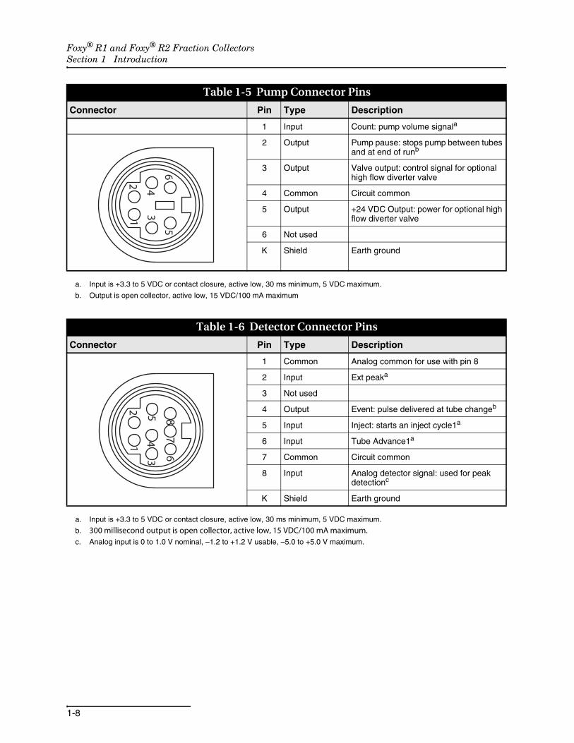
Table 1-5 Pump Connector Pins
Connector Pin Type Description
1 Input Count: pump volume signala
2 Output Pump pause: stops pump between tubes and at end of runb
3 Output Valve output: control signal for optional high flow diverter valve
4 Common Circuit common
5 Output +24 VDC Output: power for optional high flow diverter valve
6 Not used
K Shield Earth ground
a. Input is +3.3 to 5 VDC or contact closure, active low, 30 ms minimum, 5 VDC maximum.
b. Output is open collector, active low, 15 VDC/100 mA maximum
Table 1-6 Detector Connector Pins
Connector Pin Type Description
1 Common Analog common for use with pin 8
2 Input Ext peaka
3 Not used
4 Output Event: pulse delivered at tube changeb
5 Input Inject: starts an inject cycle1a
6 Input Tube Advance1a
7 Common Circuit common
8 Input Analog detector signal: used for peak detectionc
K Shield Earth ground
a. Input is +3.3 to 5 VDC or contact closure, active low, 30 ms minimum, 5 VDC maximum.
b. 300 millisecond output is open collector, active low, 15 VDC/100 mA maximum.c. Analog input is 0 to 1.0 V nominal, –1.2 to +1.2 V usable, –5.0 to +5.0 V maximum.

Foxy® R1 and Foxy® R2 Fraction CollectorsSection 1 Introduction
1-9
1.6 Accessory Cable Specifications
1.6.1 Cables for Isco Accessories
Cables are available to connect the fraction collector to Iscoequipment:
• To connect the fraction collector to a TRIS pump, order accessory cable 69-2134-172. This cable connects the Signal output from the TRIS pump to the fraction collector’s Pump connection. This cable carries the pump count and pump pause signals.
• To connect the fraction collector to an Isco UV-Vis detector such as the UA-6, order accessory cable 69-2134-173. This cable carries the analog peak detector signal, as well as the tube advance, event pulse, external peak, and inject signals.
1.6.2 Cable for non-Isco Pumps
A cable is available to connect the fraction collector to a non-Iscopump. Part number 60-2134-170 is a six-foot long cable with oneend terminated as a 6-pin mini-DIN connector. The other end isstripped and tinned for connection to the external device.
Table 1-7 RS-232 Serial Communication Connector Pins
Connector Pin Type Description
1 Not used
2 Output TxD RS-232 serial data out
3 Input RxD RS-232 serial data in
4 Reserved
5 Common Circuit common
6 Reserved
7 Not used
8 Not used
9 Not used
K Shield Earth Ground

Foxy® R1 and Foxy® R2 Fraction CollectorsSection 1 Introduction
1-10
1.6.3 Cable for non-Isco Detectors
A cable is available to connect the fraction collector to a non-Iscodetector. Part number 60-2134-171 is a six-foot long cable withone end terminated as a 8-pin mini-DIN connector. The otherend is stripped and tinned for connection to the external device.
Table 1-8 Non-Isco Pump Cable, P/N 60-2134-170
Connector Pin Color Type Description
1 BLK Input Count: pump volume signal
2 BRN Output Pump pause: stops pump between tubes and at end of run
3 RED Output Valve output: control signal for optional high flow diverter valve
4 ORN Common Circuit common
5 YEL Output +24 VDC Output: power for optional high flow diverter valve
6 GRN Not used
K N/A Shield Earth ground
Table 1-9 Non-Isco Detector Cable, P/N 60-2143-171
Connector Pin Color Type Description
1 BLK Common Analog common for use with pin 8
2 BRN Input Ext peak:
3 RED Not used
4 ORN Output Event: pulse delivered at tube change
5 YEL Input Inject: starts an inject cycle
6 GRN Input Tube Advance
7 BLU Common Circuit common
8 VIO Input Analog detector signal: used for peak detection
K N/A Shield Earth ground

2-1
Foxy® R1 and Foxy® R2 Fraction Collectors
Section 2 Preparation for Use
This section describes the setup procedures for the fraction col-lector and its optional accessories.
NoteSection 2.5 contains an Installation Qualification checklist. Ifrequired, sign off the checklist entries as you successfullycomplete the following sections.
Before attempting to assemble or operate the fraction collector,ensure that all parts listed on the packing slip are in theshipping carton(s). All items ordered, including tube racks orfunnels, are listed on the packing slip.
CAUTIONNever lift the fraction collector by the arm. Permanent damagethe arm mechanism may occur.
NoteOptional accessories ordered with the fraction collector mightbe shipped in a separate carton.
Inspect the fraction collector for damage that might haveoccurred during shipping. Notify the shipping carrier immedi-ately if you find any damage.
2.1 Preliminary Checkout Before using the fraction collector you should perform a prelim-inary checkout to ensure your unit functions properly. Thisincludes testing electrical, mechanical, and programming func-tions. To do this, enter a simple program and operate the fractioncollector.
WARNINGThe AC mains power cord is the disconnect device. Position the fraction collector so that the power cord can be unplugged, or use a power strip where the plug can quickly be removed from the outlet in the event of an emergency.

Foxy® R1 and Foxy® R2 Fraction CollectorsSection 2 Preparation for Use
2-2
WARNINGRefer to the serial number label for mains power requirements.
NoteTo perform the preliminary checkout you will need to power thefraction collector. The fraction collector is shipped with either aNorth American IEC320C13 to NEMA 5-15P power cord or aEuropean IEC320C13 to CEE7/VII power cord. If the corddoes not fit your AC mains power source, purchase a connec-tor adapter or IEC320C13 power cord from a local vendor.
CAUTIONDo not install racks, tubing, or any accessories until the prelim-inary checkout has been completed.
Should the fraction collector fail any preliminary checkout step,contact the factory or your factory-authorized representative forassistance.
1. Set the fraction collector upright on a level surface.
2. Remove any wrapping or packing materials from the frac-tion collector. The arm and diverter valve assembly should move freely.
3. Loosen the diverter valve thumb screw and raise the diverter valve to its highest position (Figure 2-1). Tighten the thumb screw to secure the diverter valve.
Figure 2-1 Adjusting the diverter valve height

Foxy® R1 and Foxy® R2 Fraction CollectorsSection 2 Preparation for Use
2-3
4. Connect the fraction collector to AC mains power using the supplied power cord. This places the fraction collector in the Standby mode. The display should be off.
5. Touch the touch screen display to turn on the fraction col-lector. The drop former will find the home position (left, rear position) and the touch screen display backlight will turn on. The display will briefly show the current rack con-figuration and then the main menu.
Figure 2-2 Main menu
NoteAppendix A contains an icon glossary for complete descrip-tions of the icons used in the preliminary checkout procedure.
6. Touch the Folder icon twice to open a list of collection meth-ods. Method A should be selected. If not, touch the up or down arrows to highlight Method A.
Figure 2-3 Method Select screen
Method AMethod B16mmTubeMethod DDefaultEDefaultFDefaultGDefaultH

Foxy® R1 and Foxy® R2 Fraction CollectorsSection 2 Preparation for Use
2-4
7. Touch the Enter icon to accept Method A and return to the screen at which you can edit the method settings.
Figure 2-4 Edit Method Settings screen
8. Touch the Time icon to display a screen at which you can modify the fraction collection based on time.
9. The fraction size option should be selected. That is, a box should appear around the tube. If not, touch the Volume Select icon to toggle between the options.
Figure 2-5 Time-based Fractions screen
10. Use the Arrow icons to set the interval to two seconds.
11. Touch the Enter icon twice to save the setting and return to the main menu.
12. Touch the Play icon to start operation. The arm and drop former will move to the first tube position and then advance to the next tube every two seconds. Allow the drop former to advance through at least 20 tubes to ensure that the arm freely moves through the X and Y axes.
13. Touch the Pause icon. The arm and drop former should stop over the current tube.
14. Touch the Stop icon. The arm and drop former will move to the home position. This completes the preliminary checkout procedure.
_2s__m__h

Foxy® R1 and Foxy® R2 Fraction CollectorsSection 2 Preparation for Use
2-5
2.2 Fluid Connections There are three points for fluid connections on the fraction col-lector. Two are on the diverter valve—In and Waste. The thirdpoint is found on the drip tray which you can route to a wastecontainer.
CAUTIONRisk of fire or explosion. Nonconductive, nonpolar liquids at lin-ear velocities greater than 40 cm/sec may develop an electro-static charge. If this applies to your application, use conductivetubing and ground the fluid path.
2.2.1 Diverter Valve Connections
NoteThe In and Waste connections use special headless fittings.The position of the ports prevent the use of standard Upchurchfittings.
The diverter valve ports are shown below.
Figure 2-6 Diverter valve ports.
To connect the fluid lines:
1. Place the unit in Standby by touching the Standby/ON icon.
2. Remove any installed racks.
3. Loosen the diverter valve thumb screw and lower the diverter valve to its lowest position (refer to Figure 2-1). This will expose the ports on the back of the diverter valve. Tighten the thumb screw to secure the diverter valve.
4. The accessory package includes a 10 ft length (3 m) of .030 inch I.D., 1/16 inch O.D. FEP tubing. Cut a length of tubing to connect between the In port and the source.
NoteCut the tubing with a tubing cutter to ensure that the end is cutcleanly and free from any deformation.
Waste(NC)
IN(Common)
Drop Former(NO)

Foxy® R1 and Foxy® R2 Fraction CollectorsSection 2 Preparation for Use
2-6
5. Prepare the tubing as shown in Figure 2-7.
Figure 2-7 Tubing preparation
6. Insert the tubing into the In port. With the tubing fully seated, thread the headless nut into the port until fin-ger-tight.
7. Unthread the headless nut and inspect the fitting. The fer-rule should be fully swaged at the end of the tubing. The following should be observed:
· the yellow ferrule should be flush and perpendicular with the end of the tubing,
· the metal lock ring should be compressed over the ferrule without any gaps,
· all pieces should be correctly aligned and free from any deformation.
If not fully swaged, reinsert the headless nut into the portand tighten further. Remove the headless nut and inspectagain using the criteria above.
8. Repeat steps 4 through 7 to prepare the tubing for the Waste port.
9. Route the headless nuts of the In and Waste fluid lines down through the tubing guide on the back of the arm. The tubing should be routed behind the metal guide pin.
10. Connect the fluid In line to the center port. Connect the other end to the liquid source with user-supplied fittings.
11. Connect the Waste line to the right-side port (when viewed from the back of the diverter valve). Route the other end to a waste collection container. The completed connections should appear as shown in Figure 2-8.
Fer
rule
Lo
ck R
ing
Hea
dle
ss N
ut
209-
0163
-24
Tapered edge of lock ring must face the yellow ferrule
209-
0163
-21
Tubing023-0502-04

Foxy® R1 and Foxy® R2 Fraction CollectorsSection 2 Preparation for Use
2-7
Figure 2-8 Connections to valve
12. Raise the diverter valve to its highest position.
13. Move the arm and diverter valve through the full range of motion. Ensure the In and Waste tubing do not obstruct the movement. If necessary, secure the tubing using the adhesive-backed clips from the accessory package.
2.2.2 Drip Tray Drain Connection
Connect the 5/16 inch I.D. clear vinyl tubing to the drip tray drainand route it to a suitable waste container.
CAUTIONConnect tubing to the drip tray drain when collecting large vol-umes, when the installed location is at risk from any overflow,or when collecting fluids that are flammable or can produceflammable vapors.
CAUTIONTo prevent fluid from pooling, drain tubing must slope down-ward from the drip tray without loops or kinks. If necessary,elevate the fraction collector by placing it on a sturdy shelf orplatform.
CAUTIONVisually inspect the drain tubing monthly to ensure that it is notobstructed. The tubing should be free of any damage, kinks,deterioration, or obstructions.

Foxy® R1 and Foxy® R2 Fraction CollectorsSection 2 Preparation for Use
2-8
2.3 Rack Installation The fraction collectors hold either one or two racks. Racks ensurethat the collection vessels are positioned correctly under the dropformer. Racks are also a convenient way to prepare the fractioncollector for operation, as well as carrying or storing collectedfluids after operation.
NoteTo prevent spills, always insert the correct vessels in the rackand verify that the rack is aligned on the guide pins.
NoteThe Foxy R2 fraction collectors will detect the installed rackusing RFID technology, and configure the operation settingsfor the detected rack and tube size.
To install a rack:
1. Select the rack and insert the collection tubes.
NoteCollection tube height must not exceed 150 mm for use withthe Foxy R1 fraction collector. Tube height must not exceed180 mm for use with the Foxy R2 fraction collector.
2. Ensure that the tops of the collection tubes are even. Tubes that do not drop fully into the rack might obstruct arm movement.
3. Grasp the rack so that tube 1 is positioned at the front left corner.
4. Align the holes on the left side of the rack with the corre-sponding guide pins (Figure 2-9) in the drip tray and gen-tly press downward. When correctly installed, both sides of the rack will sit on the ridges in the drip tray. The test tube numbers on the rack will appear upright when viewed from the front of the fraction collector.
Figure 2-9 Rack guide pins and bottle location ridges
Guide Pins
Ridges
Foxy® R1 and Foxy® R2 Fraction CollectorsSection 2 Preparation for Use
2-9
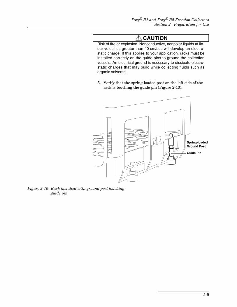
CAUTIONRisk of fire or explosion. Nonconductive, nonpolar liquids at lin-ear velocities greater than 40 cm/sec will develop an electro-static charge. If this applies to your application, racks must beinstalled correctly on the guide pins to ground the collectionvessels. An electrical ground is necessary to dissipate electro-static charges that may build while collecting fluids such asorganic solvents.
5. Verify that the spring-loaded post on the left side of the rack is touching the guide pin (Figure 2-10).
Figure 2-10 Rack installed with ground post touching guide pin
Guide Pin
Spring-loaded Ground Post

Foxy® R1 and Foxy® R2 Fraction CollectorsSection 2 Preparation for Use
2-10
2.4 Diverter Valve Adjustment
The height of the diverter valve should be adjusted to minimizethe distance above the collection tubes.
This vertical adjustment should be performed whenever differenttypes of racks or collection tubes are installed.
CAUTIONTo prevent damage to the arm, drop former, or collectiontubes, always adjust the diverter valve to its highest positionbefore installing different types of racks or tubes. After install-ing racks and tubes, lower the diverter valve to its operatingposition.
1. Ensure that the unit is in Standby. If not, touch the Standby/On icon to place the unit in Standby.
2. Move the arm and drop former to a convenient location over the installed collection rack.
3. While holding the diverter valve with one hand, loosen the thumb screw with the other. Do not remove the thumb-screw.
4. Lower the diverter valve so that the drop former is close to the top of the collection tubes (Figure 2-11). Generally, a 1/2-inch or 1 cm space between the drop former and the top of the tubes will sufficiently allow unobstructed movement of the arm.
5. Tighten the thumbscrew to secure the diverter valve posi-tion.
6. Move the diverter valve over the tubes in each corner of the rack to ensure there is clearance.
7. Turn on the fraction collector by touching the touch screen display. The arm will return to the home position. The drop former should clear the top of the tubes.
Figure 2-11 Diverter Valve adjusted with 1/2 inch or 1 cm clearance

Foxy® R1 and Foxy® R2 Fraction CollectorsSection 2 Preparation for Use
2-11
2.5 Installation Qualification Checklist
Table 5-1 Installation Qualification Checklist
Step DescriptionInstaller Initials
Operator Initials
2.1 Preliminary Checkout
2.2.1 Diverter Valve Connections
2.2.2 Drip Tray Drain Connection
2.3 Rack Installation
2.4 Diverter Valve Adjustment
Certification of Section 2 Completion
Installer Name (print):
Installer Signature:
Date:
Operator Name (print):
Operator Signature:
Date:
Comments:

Foxy® R1 and Foxy® R2 Fraction CollectorsSection 2 Preparation for Use
2-12

3-1
Foxy® R1 and Foxy® R2 Fraction Collectors
Section 3 Programming
This section contains an overview of fraction collection pro-gramming via the touch screen interface.
Programming via the touch screen supports basic collectionapplications where the fraction collector is one of several discretecomponents with or without a main controller. Control signals, ifany, are connected to the Pump or Detector connectors on theback panel.
For advanced collection applications where the fraction collectoris part of a system directed by an external controller, refer toSection 4, Serial Command Control. The fraction collector inthese applications is interfaced with an external controllingdevice through the RS-232 Serial or Ethernet connectors, as wellas the optional pump and detector inputs.
NoteThe display shows a computer icon if the system isunder remote control. Refer to Section 4 for serialcontrol programming instructions and to the docu-mentation supplied with the controlling device.
Should there be a need to control the fraction collector locally,touch the computer icon to terminate the remote control.
Additional touch screen programming resources can be found inAppendix A.
3.1 Main Menu All programming via the touch screen begins at the Main Menu(Figure 3-1).
Figure 3-1 Main Menu
Method Settings
Divert to Waste
Tube Advance
Standby
Configuration Tools
Collect in Tubes
Tube Position
Play (start method)

Foxy® R1 and Foxy® R2 Fraction CollectorsSection 3 Programming
3-2
Access the fraction collector programming by touching either theTools icon or the Folder icon:
Touch the Configuration Tools icon to view ormodify the fraction collector Configuration set-tings such as the rack type, input/output settings,
etc. The Configuration settings should be reviewed and setas required when the fraction collector is first installed,and whenever the configuration is changed thereafter.Refer to Section 3.2 for details.
Touch the Folder icon to view or modify theMethod settings. The Method settings direct theoperation of the fraction collector after you touch
the Play icon. These settings define tube change intervals,peak cutting, time windows, etc. Up to eight differentmethods can be defined, one of which is always current.For more details see Section 3.3.
The other Main Menu icons are briefly discussed below:
Touch the Diverter Valve Position icons to togglethe position of the diverter valve. When thearrow points to the tube, the valve is set to col-
lect fluids in tubes. When the arrow points to the wastecan, the valve is set to route fluids to waste.
Touch the Next Tube icon to advance the dropformer to the next tube position. The current tubeposition is reported next to this icon.
Touch the Play icon to start the current method.
Touch the Power icon to place the fraction collec-tor in the Standby state.
3.2 Configuration Settings Configuration settings define the overall fraction collector oper-ation. That is, these lower-level settings are applicableregardless of whichever collection Method is selected.
The fraction collector displays the Configuration menu (Figure3-2) when you touch the Configuration Tools icon.
When you first install the fraction collector, these settings shouldbe reviewed and set as necessary. Also, update the settingswhenever the configuration changes. Sections 3.2.1 through 3.2.7provide details for each of the Configuration Tools menu options.

Foxy® R1 and Foxy® R2 Fraction CollectorsSection 3 Programming
3-3
Figure 3-2 Configuration Tools Menu
3.2.1 Rack Settings Touch the rack icon to view the Rack options menu (Figure 3-3).From this menu you can view or change the type of rack, set thecollection pattern and speed, and calibrate the drop formerposition over the rack.
Figure 3-3 Rack options menu
Rack 1 and Rack 2Note
The two-rack Foxy R2 fraction collector uses radio frequencyidentification (RFID) technology to automatically detect therack types. The Rack options menu displays the detected racktypes.
The Rack 1 and Rack 2 options report the current Rack type. Onthe Foxy R2 fraction collector, rack types are automaticallydetected whenever the touch screen display returns to the Mainmenu. Therefore, setting the rack type for the Foxy R2 is not nec-essary.
To change the rack type (not recommended on Foxy R2 fractioncollectors):
1. Touch the Rack 1 or Rack 2 settings to open a list of sup-ported rack types.
2. Select the desired rack type from the list using the Up and Down Arrow buttons.
Rack Settings
TCP/IP Settings
Pump Control Settings
Fraction collector information
Enter
RS-232 Serial Settings
Inject Options
Analog Peak Settings
13mmx144
none
Tube Advance Speed
Rack 2 (Back) Foxy R2 Only
Calibrate
Rack 1 (Front)
Enter
Collection Pattern

Foxy® R1 and Foxy® R2 Fraction CollectorsSection 3 Programming
3-4
NoteThe selected rack type should match the installed rack. Other-wise, fluids may miss the collection tube openings.
3. Touch the Enter icon to save the selection and return to the Rack Options menu.
NoteTouching the Enter icon again will return the fraction collectorto the Configuration Tools menu. Touching it once more willdisplay the Main menu.
Tube Advance Speed The fraction collector can vary the speed of the tube advancemotion. Higher flow rate, or higher viscosity liquids may causesome liquid to miss the tube opening during tube changes. TheTube Advance Speed setting allows you to minimize this effect.
To adjust the Tube Advance Speed:
1. Touch the Tube Advance Speed (Rabbit) icon.
2. The left side of the display shows the speed setting. Increase or decrease the speed by touching the rabbit (faster) icon or the turtle (slower) icon.
3. Touch the Enter icon to save the calibration settings. Collection Pattern The collection pattern icon displays the selected pattern—either
left-to-right or serpentine. Touch the icon to toggle the selections.
Calibrate The factory calibration positions the drop former over the col-lection tubes for all available rack types. Calibration is not nec-essary for most applications and commercially-availablecollection vessels.
Some applications or collection vessels require calibration tofurther refine the drop former position. This need is evidentwhen the drops fall on or beyond the rim of the collection vessel.
NoteIf the only drops that fall on or beyond the rim are those imme-diately following a tube advance, the problem is not due to cal-ibration. Instead, lowering the drop former (section 2.4) oradjusting Tube Advance Speed might prevent this condition.Additionally, consider stopping the fluid delivery pump duringtube changes (Section 3.2.5).
Should calibration be necessary:
1. Ensure that the fraction collector is level.
2. Load the rack with the collection vessels and place the rack on the system.
3. Touch the Calibrate icon to access the calibration options.
4. Touch the First Tube icon to move the drop former over the front and left-most tube in the rack.

Foxy® R1 and Foxy® R2 Fraction CollectorsSection 3 Programming
3-5
5. Touch the Arrow buttons to incrementally position the drop former over the center of the collection vessel opening.
NoteThe white diverter valve housing has a arrow on the face toindicate the center of the drop former outlet. This can assistwith the left-to-right (X-axis) positioning.
6. When the first tube position is calibrated, touch the Last Tube icon to move the drop former over the back and right-most tube.
7. Touch the Arrow buttons to position the drop former over the center of the collection vessel opening.
8. Touch the enter icon to save the calibration settings. By calibrating the drop former position over the first and lasttubes, the fraction collector calculates the position of all othertubes in the rack.
3.2.2 RS-232 Serial Settings External devices can communicate with the fraction collector.One option is through the RS-232 Serial port. Many of the com-munication parameters are predefined by the firmware:
• Supports ASCII printable characters
• 8-bit
• No parity bit
• 1 stop bit.The user-configurable parameter is the baud rate. To set thebaud rate:
1. Touch the RS-232 Serial settings icon.
2. Select the desired baud rate from the list using the Up and Down Arrow buttons.
3. Touch the Enter icon to save the selection and return to the Configuration Tools menu.
NoteRefer to Section 4 for more information on communicationswith external devices.
3.2.3 TCP/IP Settings External devices may communicate with the fraction collectorusing TCP/IP protocol and a static IP address. To configure theTCP/IP settings:
1. Touch the TCP/IP settings icon to display the communica-tion options.
2. Review the IP and IP Mask values. To change either value:
a. Touch the value you intend to modify.
b. Touch the Up and Down Arrow icons to set the numeri-cal value at the cursor position.

Foxy® R1 and Foxy® R2 Fraction CollectorsSection 3 Programming
3-6
c. Move the cursor position by touching the Left and Right Arrow icons.
d. Touch the Enter icon to save the setting and return to the previous display.
NoteShould you need assistance with determining the correct IPand IP Mask values, contact your organization’s IT depart-ment.
NoteThe view-only MAC address is unique to each fraction collec-tor and cannot be changed.
3.2.4 Inject Options Inject options, also known as Restart options, control the oper-ation of the fraction collector when collecting fractions from mul-tiple samples.
Touching the Inject icon displays a list of options.
None If you intend to collect fractions from a single sample aftertouching the Play button, select the None option. The fractioncollector will collect fluids until the last tube, or until stopped.
Inject or timed If you intend to collect fractions from multiple samples during arun, choose an Inject or Timed option. The difference is themeans used to restart the collection of each sample.
Inject – The inject options rely on an Inject signal from anexternal device. The fraction collector receives this electricalpulse input on pin 5 of the Detector connector.
When first started (Figure 3-4, Start of Run) using one of theInject options, the fraction collector pauses so that the samplecan be injected, as indicated by the Play icon alternating with theInject icon. Touch the Play/Inject icon after the sample injectionto resume the operation.
Figure 3-4 Inject options timing diagram
S1 S2 S3
Play
Pauses for InjectSamples
Inject Signal
Play/Inject
Play/Inject
Play/Inject
Run
Restart1
Restart2
Restart3
Start of Run

Foxy® R1 and Foxy® R2 Fraction CollectorsSection 3 Programming
3-7
The fraction collector advances through collection tubes as pro-grammed by its method settings until it receives an Inject signalat pin 5 (Figure 3-4, Restart 1). The fraction collector pausesagain for the injection. When you touch the Play/Inject icon, thefraction collector moves to the tube defined by the overlay, next,or skip options. This process repeats until the end of the run.
Timed – The timed options do not rely on external signals, nordoes it pause for injections. When using one of the timed options,the fraction collector assumes that each of the multiple sampleinjections are performed at fixed time intervals.
For example, the chemist injects a sample and touches the Playicon to start the run (Figure 3-5). Thereafter, another sample isinjected at every five minute interval. Every five minutes thefraction collector automatically restarts and moves to the tubedefined by the overlay, next, or skip options. This process repeatsuntil the end of the run.
To set the time restart interval:
1. Touch the Arrow buttons to select a Timed option. A Folder icon appears at the top of the display.
2. Touch the Folder icon to open the Timed interval settings.
3. Enter the hours, minutes, and seconds for the interval. Move the cursor position by touching the Left and Right Arrow icons. Touch the Up and Down Arrow icons to set the numerical value at the cursor position.
4. Touch the Enter icon to save the setting and return to the previous display.
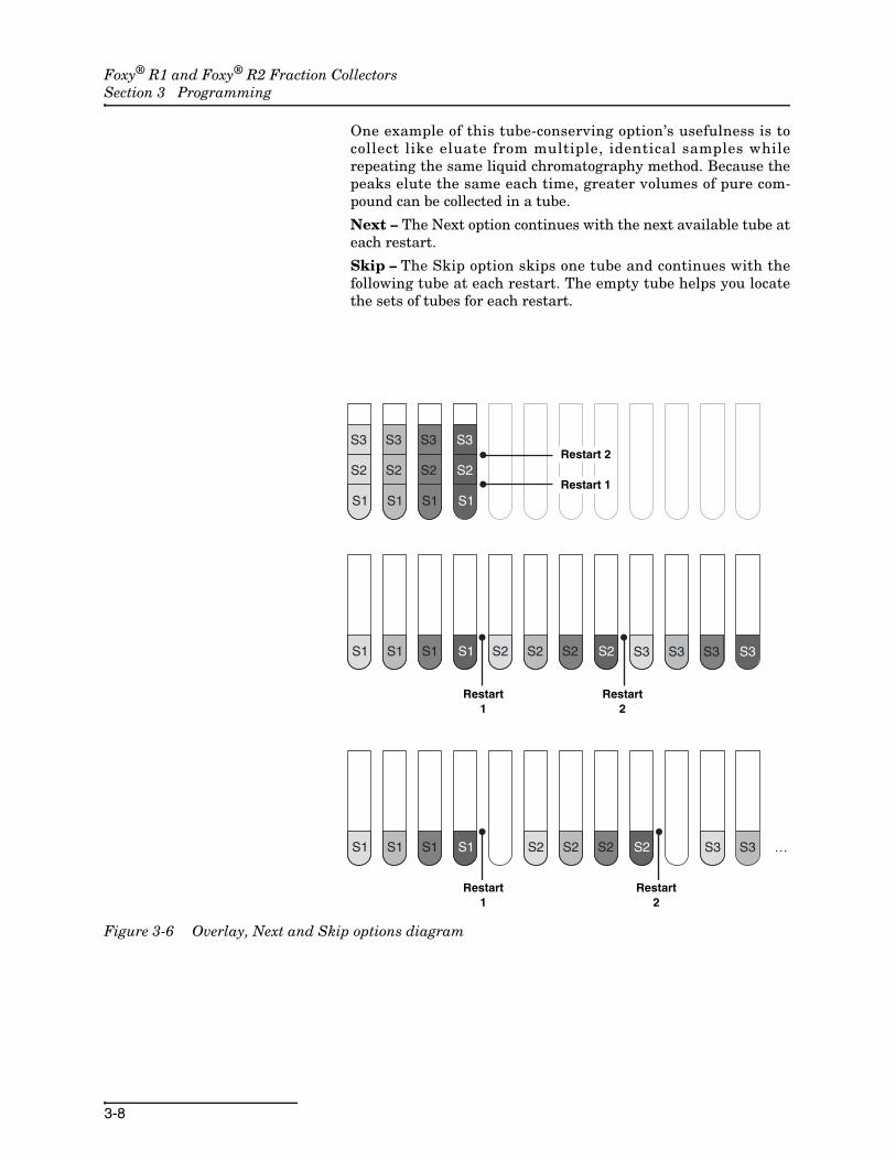
Overlay, Next, or Skip The Inject or Timed restart options are combined with a col-lection tube option: Overlay, Next, or Skip. These options areillustrated in Figure 3-6.
Overlay – If you select the overlay option, the fraction collectormoves the drop former back to the original tube position. That is,at every restart, the drop former returns to the tube positionfrom which the run was started.
Figure 3-5 Timed options timing diagram
S1 S2 S3 S4 …
Play
Samples
Run
Restart1
Start of Run
Restart2
Restart3
Restart4
Foxy® R1 and Foxy® R2 Fraction CollectorsSection 3 Programming
3-8
One example of this tube-conserving option’s usefulness is tocollect like eluate from multiple, identical samples whilerepeating the same liquid chromatography method. Because thepeaks elute the same each time, greater volumes of pure com-pound can be collected in a tube.
Next – The Next option continues with the next available tube ateach restart.
Skip – The Skip option skips one tube and continues with thefollowing tube at each restart. The empty tube helps you locatethe sets of tubes for each restart.
Figure 3-6 Overlay, Next and Skip options diagram
S1 S1 S1 S1
S1 S1 S1 S1
S1 S1 S1 S1
S2 S2 S2 S2
S2 S2 S2 S2
S2 S2 S2 S2
S3 S3 S3 S3
S3 S3 S3 S3
S3 S3 …
Restart1
Restart2
Restart1
Restart2
Restart 1
Restart 2

Foxy® R1 and Foxy® R2 Fraction CollectorsSection 3 Programming
3-9
3.2.5 Pump Control Settings The fraction collector can control an external pump from pin 2 ofthe Pump connector. This signal is used to pause the pumpduring tube changes.
Touch the Pump Control icon to view the current setting.
The icon with the “1” (left) indicates thatthe fraction collector will not send apause signal from pin 2. In this state,
the external pump will continue to operate during tubechanges. The icon with the “0” indicates that the fractioncollector will send a pause signal from pin 2. Touch theicon to toggle the state.
3.2.6 Analog Peak Settings The fraction collector can receive an analog peak signal from anexternal detector. The fraction collector receives this signal atpin 8 of the Detector connector.
When using this feature, set the analog peak voltage scale to therange of the detector signal, either 1000 mV, 100 mV, or 10 mV.Touch the Analog Peak setting icon to view and select the rangeusing the Up and Down Arrows.
Choose the voltage that corresponds to your detection device’s100% signal output. If your detector does not scale its output toone of the options, choose the option just above your highestexpected peak voltage.
If you select the External option, the fraction collector will ignorethe signal at pin 8 and monitor the TTL signal at pin 2 instead.The fraction collector begins cutting peaks when an active low ispresent.
3.2.7 Fraction Collector Information
Touch the Information icon to display Model number andhardware/firmware revisions.
Foxy® R1 and Foxy® R2 Fraction CollectorsSection 3 Programming
3-10
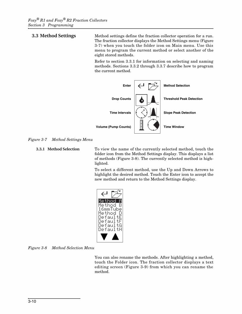
3.3 Method Settings Method settings define the fraction collector operation for a run.The fraction collector displays the Method Settings menu (Figure3-7) when you touch the folder icon on Main menu. Use thismenu to program the current method or select another of theeight stored methods.
Refer to section 3.3.1 for information on selecting and namingmethods. Sections 3.3.2 through 3.3.7 describe how to programthe current method.
Figure 3-7 Method Settings Menu
3.3.1 Method Selection To view the name of the currently selected method, touch thefolder icon from the Method Settings display. This displays a listof methods (Figure 3-8). The currently selected method is high-lighted.
To select a different method, use the Up and Down Arrows tohighlight the desired method. Touch the Enter icon to accept thenew method and return to the Method Settings display.
Figure 3-8 Method Selection Menu
You can also rename the methods. After highlighting a method,touch the Folder icon. The fraction collector displays a textediting screen (Figure 3-9) from which you can rename themethod.
Method Selection
Threshold Peak Detection
Slope Peak Detection
Time Window
Enter
Drop Counts
Time Intervals
Volume (Pump Counts)
Method A
16mmTubeMethod DDefaultEDefaultFDefaultGDefaultH
Method B

Foxy® R1 and Foxy® R2 Fraction CollectorsSection 3 Programming
3-11
Figure 3-9 Rename Method display
Use the Left and Right Arrows to move the cursor and the Upand Down Arrows to change the character or number. When com-plete, touch the Enter icon to save the name and return to theMethod Selection menu.
3.3.2 Drop Counts Drop counting creates fractions by advancing the drop former ata fixed number of drops. This option uses a photosensor devicepositioned just below the drop former.
NoteDrop counting can create relatively uniform collection tube vol-umes even when the delivered flow rate varies.
NoteThe drop count option assumes that the flow rate is slowenough to produce drops instead of a stream of liquid.
To create fractions based on drop counts:
1. Touch the Drop Count icon to open the settings display (Figure 3-10).
Figure 3-10 Drop Counts display
Method A
__1

Foxy® R1 and Foxy® R2 Fraction CollectorsSection 3 Programming
3-12
Use this display to set the fraction volume—expressed as anumber of drops, and the flow delay volume—expressed astime.
2. Ensure that the fraction volume setting is active as indi-cated by the Volume Select icon. That is, the tube should be highlighted with a border. If not, touch the icon to toggle the setting.
3. Enter the fraction volume as 1 to 999 drops using the arrow icons. The Up and Down Arrows increment or decre-ment the numbers, the Left and Right Arrows move the cursor position.
4. Touch the Volume Select icon to display the Flow Delay volume. The hourglass should be highlighted with a bor-der.
5. Enter the Flow Delay volume as hours, minutes, and sec-onds using the Arrow icons. The Up and Down Arrows increment or decrement the numbers, the Left and Right Arrows move the cursor position.
6. Touch the Enter icon to return to the Methods Settings menu.
About Flow Delays
A Flow Delay synchronizes the tube changes withsample flow to make precise peak cutting possible. Theflow delay time is the time required for a fraction totravel from your detector to the fraction collector’s dropformer. The delay depends on the flow rate and thesize of the tubing between the fraction collector and thedetector.
To calculate the flow delay time, use this formula:
T = V ⁄ Q
Where T is the delay time in seconds, V is the internalvolume of the tubing, and Q is the flow rate, (in thesame units as V) per second.
The volume of the tubing can be calculated by:
V = π ⁄ 4 × D2 × L or expressed as: V= 0.7854 × D2 × L
Where L is the tubing length and D is the insidediameter.
An easy, alternative way to find the delay time is tointroduce a bubble ahead of the detector and measurethe delay to the drop former.

Foxy® R1 and Foxy® R2 Fraction CollectorsSection 3 Programming
3-13
3.3.3 Time Intervals Time intervals create fractions by advancing the drop former at afixed time intervals. This option uses an internal clock.
NoteTime intervals can create widely varying collection tube vol-umes if the delivered flow rate is variable.
To create fractions based on time intervals:
1. Touch the Time Intervals icon to open the settings display (Figure 3-11).
Figure 3-11 Time Intervals display
Use this display to set the fraction volume and delayvolume—both expressed as hours, minutes, and seconds.
2. Ensure that the fraction volume setting is active as indi-cated by the Volume Select icon. That is, the tube should be highlighted with a border. If not, touch the icon to toggle the setting.
3. Enter the fraction volume as hours, minutes, and seconds using the arrow icons. The Up and Down Arrows incre-ment or decrement the numbers, the Left and Right Arrows move the cursor position.
4. Touch the Volume Select icon to display the Flow Delay. The hourglass should be highlighted with a border.
5. Enter the Flow Delay volume as hours, minutes, and sec-onds using the Arrow icons. The Up and Down Arrows increment or decrement the numbers, the Left and Right Arrows move the cursor position.
6. Touch the Enter icon to return to the Methods Settings menu.
__1

Foxy® R1 and Foxy® R2 Fraction CollectorsSection 3 Programming
3-14
3.3.4 Volume The Volume option creates fractions by advancing the dropformer at a fixed number of pump counts. This option relies on apump count signal delivered by an external device to pin 1 of thefraction collector’s Pump connector.
NoteThe Volume option can create relatively uniform collectiontube volumes even when the delivered flow rate varies.
Refer to the documentation provided by the pump manufacturerto determine the volume delivered for each pump count.
To create fractions based using the volume option:
1. Touch the Volume icon to open the settings display (Figure 3-12).
Figure 3-12 Volume display
Use this display to set the fraction volume and delayvolume—both expressed as pump counts.
2. Ensure that the fraction volume setting is active as indi-cated by the Volume Select icon. That is, the tube should be highlighted with a border. If not, touch the icon to toggle the setting.
3. Enter the fraction volume as 1 to 999 counts using the arrow icons. The Up and Down Arrows increment or decre-ment the numbers, the Left and Right Arrows move the cursor position. For example, if the pump delivers 2 mL each pump count and the fraction size should be 24 mL, enter 12 pump counts.
4. Touch the Volume Select icon to display the Flow Delay. The hourglass should be highlighted with a border.
__1

Foxy® R1 and Foxy® R2 Fraction CollectorsSection 3 Programming
3-15
5. Enter the Flow Delay volume as 1 to 999 counts using the arrow icons. The Up and Down Arrows increment or decre-ment the numbers, the Left and Right Arrows move the cursor position.To calculate the number of pump counts for the delay vol-ume:
Pcounts = (π ⁄ 4 × D2 × L) ⁄ Pvol, otherwise expressed as:Pcounts = (0.7854 × D2 × L) ⁄ Pvol
Where L is the tubing length and D is the inside diameter.Pvol is the volume delivered for each pump count. Round tothe nearest whole number.
NoteFor the greatest possible flow delay volume accuracy, cut thetubing so that it holds a multiple of the of the pump count vol-ume.
6. Touch the Enter icon to return to the Methods Settings menu.
3.3.5 Threshold Detection Threshold detection isolates the most concentrated portion ofpeaks. The threshold is set as a percentage of the maximuminput signal. When the input signal rises above this thresholdvalue, the fraction collector performs a tube advance to isolatethe peak.
An example of threshold peak detection and collection is shownin Figure 3-13. The peaks on the analog signal are numbered 1through 4. The fraction collector ignores the first peak because itis below the 10% threshold. It isolates peaks 2 through 4 in col-lection tubes because the peak signal exceeds the threshold.
Figure 3-13 Threshold detection cuts peaks when external peak signal exceeds set percentage
To program the fraction collector for Threshold peak detection:
1. Touch the Threshold Detection icon from the Method Set-tings menu to open the threshold menu (Figure 3-14).
Time Isolated Peaks (grey)
Per
cen
t
1
2
3
4

Foxy® R1 and Foxy® R2 Fraction CollectorsSection 3 Programming
3-16
Figure 3-14 Threshold Settings menu
2. Enter the threshold as 1 to 99 percent using the Arrow icons. The Up and Down Arrows increment or decrement the numbers, the Left and Right Arrows move the cursor.
3. The icon next to the percentage shows what the fraction collector will do with non-peak fluids. The icon that is clear below the threshold indicates that non-peak fluids will be diverted to waste. The icon that is shaded below the threshold indicates that non-peak fluids will be collected in tubes. Touch the icon to toggle the selection.
4. Threshold peak detection can be used alone or combined with slope detection. You can control these options using the icon in the upper right corner of the display.
· The None icon (left) indicates that Threshold detection is Off.
· The Intersection Venn diagram icon (middle) indicates that both Threshold and Slope detection must be true before the fraction collector isolates the peak. This is also considered a logical AND.
· The Union Venn diagram icon (right) indicates that when either Threshold or Slope detection are true fraction collector isolates the peak. This is also considered a logical OR.
Touch the icon to toggle the selection.
NoteIf you are using only threshold detection, select either theUnion (OR) or Intersection (AND) option. Ensure that the peakwidth detection is set to None.
5. Touch the Enter icon to return to the Method Settings menu.
_10%

Foxy® R1 and Foxy® R2 Fraction CollectorsSection 3 Programming
3-17
3.3.6 Peak Width Detection Peak Width detection isolates small and large magnitude peaks.The Peak Width is set as the average time duration of theexpected peaks. The fraction collector monitors the slope of theinput signal. (Peak width detection is also commonly called Slopedetection.) If the rising signal is consistent with that of a peak,the fraction collector isolates the fluid. In a similar way, thefalling slope as it transitions to the baseline indicates the end ofa peak. The internal slope detection algorithms are effective inisolating multiple “shouldered,” peaks — peaks that do notreturn to the baseline before the next peak occurs.
The peak width option is useful to eliminate false peaks that canresult from a rising or noisy baseline.
An example of Peak Width detection and collection is shown inFigure 3-15. The peaks on the analog signal are numbered 1through 4. The fraction collector isolates peaks 1 through 3 incollection tubes because of the slope of the peak signal. Peak 4 isignored because the signal does not indicate a slope within theprogrammed peak width setting.
Figure 3-15 Peak Width detection cuts peaks when internal slope algorithms indicate a peak
To program the fraction collector for Peak Width detection:
1. Touch the Peak Width Detection icon from the Method Set-tings menu to open the threshold menu (Figure 3-16).
Figure 3-16 Peak Width Settings menu
Time Isolated Peaks (grey)
Per
cen
t
1
2
3
4
0h
0s
1m
Foxy® R1 and Foxy® R2 Fraction CollectorsSection 3 Programming
3-18
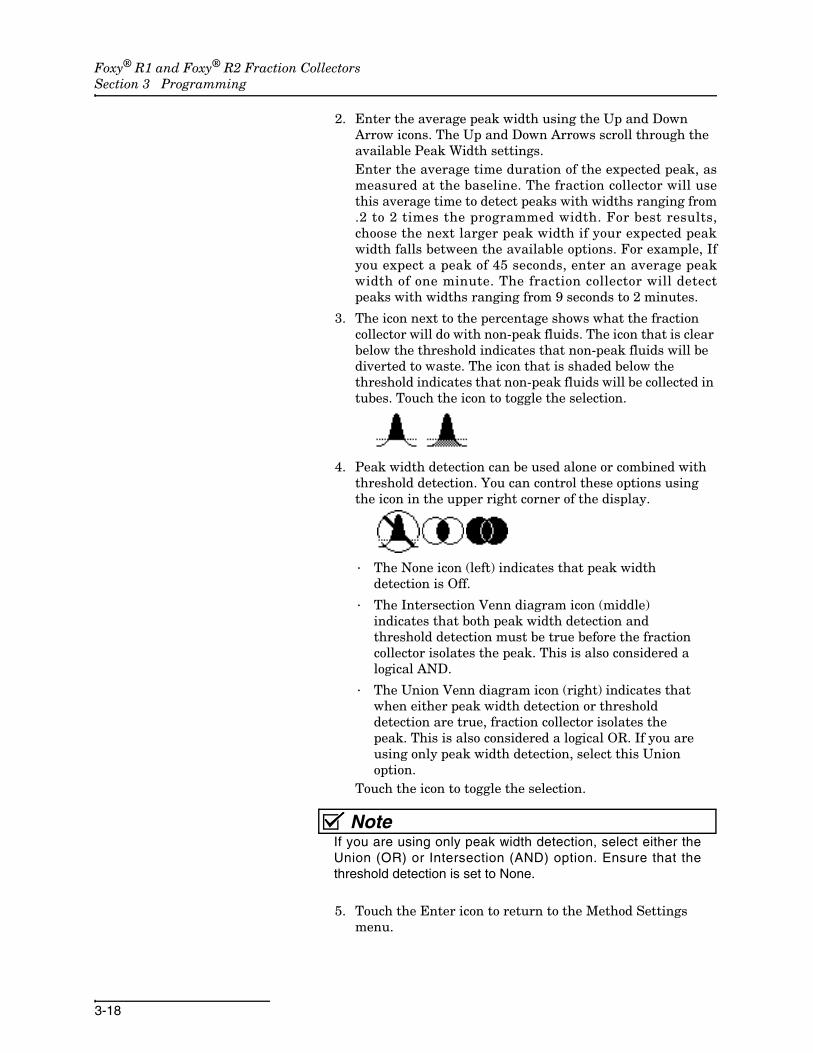
2. Enter the average peak width using the Up and Down Arrow icons. The Up and Down Arrows scroll through the available Peak Width settings.Enter the average time duration of the expected peak, asmeasured at the baseline. The fraction collector will usethis average time to detect peaks with widths ranging from.2 to 2 times the programmed width. For best results,choose the next larger peak width if your expected peakwidth falls between the available options. For example, Ifyou expect a peak of 45 seconds, enter an average peakwidth of one minute. The fraction collector will detectpeaks with widths ranging from 9 seconds to 2 minutes.
3. The icon next to the percentage shows what the fraction collector will do with non-peak fluids. The icon that is clear below the threshold indicates that non-peak fluids will be diverted to waste. The icon that is shaded below the threshold indicates that non-peak fluids will be collected in tubes. Touch the icon to toggle the selection.
4. Peak width detection can be used alone or combined with threshold detection. You can control these options using the icon in the upper right corner of the display.
· The None icon (left) indicates that peak width detection is Off.
· The Intersection Venn diagram icon (middle) indicates that both peak width detection and threshold detection must be true before the fraction collector isolates the peak. This is also considered a logical AND.
· The Union Venn diagram icon (right) indicates that when either peak width detection or threshold detection are true, fraction collector isolates the peak. This is also considered a logical OR. If you are using only peak width detection, select this Union option.
Touch the icon to toggle the selection.
NoteIf you are using only peak width detection, select either theUnion (OR) or Intersection (AND) option. Ensure that thethreshold detection is set to None.
5. Touch the Enter icon to return to the Method Settings menu.

Foxy® R1 and Foxy® R2 Fraction CollectorsSection 3 Programming
3-19
About Combining Peak Detection Options
The Union and Intersection icons allow you to combine peak detection methods. If you have programmed bothpeak detection methods this setting will determine whether both or any one of the peak conditions must be true.Refer to the diagrams below for a comparison.
Intersection (AND)The fraction collector cuts peaks 2 and 3where the input signal exceeds thethreshold value and a slope is determinedby the peak width setting.
Union (OR)The fraction collector cuts peaks 1through 4 wherever the input signalexceeds the threshold value or a slope isdetermined by the peak width setting.
Time Isolated Peaks (grey)
Per
cen
t1
2
3
4
Time Isolated Peaks (grey)
Per
cen
t
1
2
3
4

Foxy® R1 and Foxy® R2 Fraction CollectorsSection 3 Programming
3-20
3.3.7 Time Window The Time window function allows the selection of a portion of therunning time during which the fraction collector should collect. Atime window may be used for several applications: they can beused to reject peaks of no interest to you, to cut peaks to increasethe concentration of the sample, or to divert initial waste volume.
An example of this type of collection is shown in Figure 3-20. Inthis figure a time window is combined with threshold peakdetection. The fraction collector ignores peaks until the timewindow starts. It continues to collect peaks until the end of thetime window. If you are collecting only peak fluids, the fractioncollector stops the run at the end of the time window.
Figure 3-17 A Time Window limits the collection to the defined window
To program a Time Window:
1. Touch the Time Window icon from the Method Settings menu to open the menu (Figure 3-18).
Figure 3-18 Time Window Settings menu
TimeIsolated Peaks (grey)
Per
cen
t
1
2
3
4
Time WindowStart
Time WindowEnd
__h
__s
_3m

Foxy® R1 and Foxy® R2 Fraction CollectorsSection 3 Programming
3-21
2. Time Windows are either Off or combined with the selected peak detection where all conditions must be true. Touch the icon in the upper right corner to select the intersection (AND) option.
3. Enter the start time using the Arrow icons. The Up and Down Arrows increment and decrement the value; the Left Arrow moves the cursor position. The Time Window Start value is the time from the start of the run (pressing the Play icon).
4. Touch the Start/End icon to select the Time Window End setting.
5. Enter the end time. This value is the time from the start of the run.
6. Touch the Enter icon to return to the Method Settings menu.

Foxy® R1 and Foxy® R2 Fraction CollectorsSection 3 Programming
3-22
4-1
Foxy® R1 and Foxy® R2 Fraction Collectors
Section 4 Serial Command Control
4.1 Introduction The fraction collector has built-in RS-232 and Ethernet inter-faces that allow it to be remotely controlled. Remote control istypically done using a computer running a terminal program tosend commands and receive data. Software applications such asLabVIEW1 can automate the fraction collector operation.
4.2 RS-232 Communication Information
The minimum connections required for serial control are:
Available baud rates are 1200, 2400, 4800, 9600, 19200, 38400,56800, and 115200. Configure the remote device for 8 bits, noparity, 1 stop bit, and no flow control.
4.3 Ethernet Communication Information
Communication with the fraction collector can be establishedthrough either Ethernet port. These connections use a Category5 (or higher) cable. The fraction collector will automaticallydetect straight and cross-over cables and configure the communi-cation accordingly.
Refer to Section 3 to configure the TCP/IP settings of the fractioncollector.
Configure the remote device for 19,200 baud, 8 bits, no parity, 1stop bit, and no flow control. The fraction collector uses port 23for remote control and communication.
NoteAlthough the fraction collector uses port 23, commands spe-cific to TELNET protocol will be ignored.
4.4 General Command Information
4.4.1 Character Format ASCII printable characters are transmitted as 8 data bits, noparity bit, and 1 stop bit.
1. LabVIEW is a trademark of National Instruments Corporation.
Pin 2 TRANSMIT Serial data output to computer
Pin 3 RECEIVE Serial data input to computer
Pin 5 COMMON Common for all signals

Foxy® R1 and Foxy® R2 Fraction CollectorsSection 4 Serial Command Control
4-2
4.4.2 Command Syntax Commands consist of single keywords, possibly followed by anoperand separated by a “=”, for example: BAUD or TUBE=42.Commands may be abbreviated to as few as three characters.Spaces are ignored. Backspace, (ASCII character 8), may be usedto correct mistakes. Commands are not case-sensitive.
4.4.3 Line Syntax Commands are processed when a carriage return is received.Multiple commands may be sent on a line, separated by semi-colons (;), for example: NEXT;NEXT;RSVP. Total line length mustnot exceed 80 characters. Errors occurring from any command donot stop the execution of the remaining commands on line.
4.4.4 Modes The fraction collector must be in remote mode to do anythingother than read values. See REMOTE on page 4-4) for more infor-mation. Program parameters cannot be changed while a run is inprogress. Also, changes to any parameter currently being editedon the fraction collector display will not be effective.
4.4.5 Errors Errors relating to the syntax of commands result in problemmessage responses. (See Problem Responses on page 4-17)Hardware related errors (warnings and failures) are indicated bythe display and audio output of the unit, and can be detectedserially using the STATUS command.
4.4.6 Timing The fraction collector’s response time to most commands is 50milliseconds. One exception is commands that require somemechanical action such as arm movement. Mechanical actionsnormally do not exceed 4 seconds. Other exceptions are notedwhere applicable.
4.5 Serial Commands The following is a list of all fraction collector serial commands,with a brief description and example of the use for eachcommand. For some commands, no response is required orexpected from the unit. The examples show this as Response:(none).
4.5.1 Miscellaneous Commands
CLEAR This command resets the unit. It is equivalent toswitching the unit to standby and then back to operate.
CUE=n This command enables or disables the sending of a “>”prompt character when the unit is finished processing acommand line and is ready for another. This “line pacing” can beused by many terminal programs to avoid downloading com-mands faster than the unit can execute them. CUE=1 will enablethe prompt, CUE=0 will disable it. CUE=0 is set when unit isswitched to OPERATE.
Example: Command: CLEAR
Response: (none)
Foxy® R1 and Foxy® R2 Fraction CollectorsSection 4 Serial Command Control
4-3
CUE without an operand returns the current setting.
ECHO=n This command enables or disables echoing of char-acters received. Echoing can be used to verify correct reception ofcharacters. ECHO=1 will enable the echoing, ECHO=0 willdisable it. ECHO=0 is set when unit is switched to OPERATE.
ECHO without an operand returns the current setting.
HELP The unit will respond to this command with a list ofvalid command names.
Combining the HELP command with a valid command using the“$” symbol will return more information for select commands.
IDENTIFY This commands returns information identifyingthe unit.
Example: Command: CUE=1
Response: >
Example: Command: CUE
Response: CUE=1
Example: Command: ECHO=1
Response: (none)
Example: Command: ECHO
Response: ECHO=1
Example: Command: HELP
Response: CLEAR COLLECT…
Example: Command: HELP$BAUD
Response: sets & queries the serial port baud rate…
Example: Command: IDENTIFY
Response: SERIES=3870-010, FoxyR1, FRAC. COL., REV a, 01.00.00

Foxy® R1 and Foxy® R2 Fraction CollectorsSection 4 Serial Command Control
4-4
LINEFEED This command enables (LINEFEED=1) or disables(LINEFEED=0) the sending of a linefeed character each time acarriage return is sent. LINEFEED=0 is set when unit is switchedto OPERATE.
LINEFEED without an operand returns the current setting.
LOCAL This command sets the unit to local mode. In localmode, serial commands cannot affect the unit’s operation; com-mands can only obtain information. Local mode is set when theunit is switched to OPERATE. See REMOTE on page 4-4.
NOTE=text or NOTE This command and any following textare ignored by the unit. This allows annotating program files foruser reference. NOTE without a operand can provide spacing forreadability.
REMOTE This command sets the unit to remote mode. Theunit must be put into remote mode before any commands aresent that affect the unit. See also LOCAL on page 4-4.
NoteThe touch screen on the unit is still operational in remotemode. You can return the fraction collector to the Local modefrom the touch screen by touching the computer icon.
Example: Command: LINEFEED=1
Response: (none)
Example: Command: LINEFEED
Response: LINEFEED=0
Example: Command: LOCAL
Response: (none)
Example: Command: NOTE=Use with column 3 at 3 mL/min
Response: (none)
Example: Command: REMOTE
Response: (none)

Foxy® R1 and Foxy® R2 Fraction CollectorsSection 4 Serial Command Control
4-5
RSVP This command instructs the unit to indicate completionof the preceding commands that take some time to perform. Theresponse from the unit will be READY when the task is complete.For example, if you have sent RACK=1;RSVP, the unit moves thedrop former over the rack and then responds: READY.
STATUS The unit will respond to this command with the lastwarning or failure code that occurred. If an action is in progress,the unit will wait to respond, so a response of STATUS=0 meansthe preceding commands are complete and no errors occurred.For example, the command string
STATUS=0;RACK=1;TUBE=1;STATUS
will cause the unit to respond with STATUS=0 after the unit hassuccessfully moved to tube 1.
The possible status codes are:
• 0 No Failure
• 1 Failure to home inward minor axis
• 2 Failure to home inward major axis
• 3 Failure to home inward both major and minor axes
• 4 Failure to home outward minor axis
• 5 Failure to home outward major axis
• 6 Failure to home outward both major and minor axes
• 7 Failure of major axis position sensor
• 8 Failure of minor axis position sensor
• 9 Failure of major axis position correction
• 10 Failure of minor axis position correction
• 11 Failure of both major and minor axes position correction
The STATUS=0 command clears the last warning or failure codefrom memory so that future errors can be noted.
Example: Command: RSVP
Response: READY
Example: Command: STATUS
Response: STATUS=0
Example: Command: STATUS=0
Response: (none)

Foxy® R1 and Foxy® R2 Fraction CollectorsSection 4 Serial Command Control
4-6
Unsupported Miscellaneous Commands The fo l lowingserial commands are not supported by the Foxy R1 and R2fraction collector.
• DISPLAY
• KEY=keysThese commands were available for earlier fraction collectormodels. Do not use them with the Foxy R1 and R2 fraction col-lectors.
4.5.2 Immediate Control Commands
COLLECT The unit resumes collecting fractions after aDRAIN command if this command is given during a run. Oth-erwise, this command will instruct the fraction collector to movethe drop former over the tubes and open the valve. See also theDRAIN command.
DETECTOR
The unit responds to this command with the current peakdetector input value in volts.
DRAIN This command halts collecting. If executed during arun, it is the same as touching the Waste icon. The three-wayvalve diverts the flow to waste. See also the COLLECTcommand.
HOME The unit will re-home itself to verify position, even if itis already at home position.
NEXTTUBE The unit will advance the current tube numberone tube.
Example: Command: COLLECT
Response: (none)
Example: Command: DETECTOR
Response: DETECTOR=0.00014
Example: Command: DRAIN
Response: (none)
Example: Command: HOME
Response: (none)
Example: Command: NEXTTUBE
Response: (none)
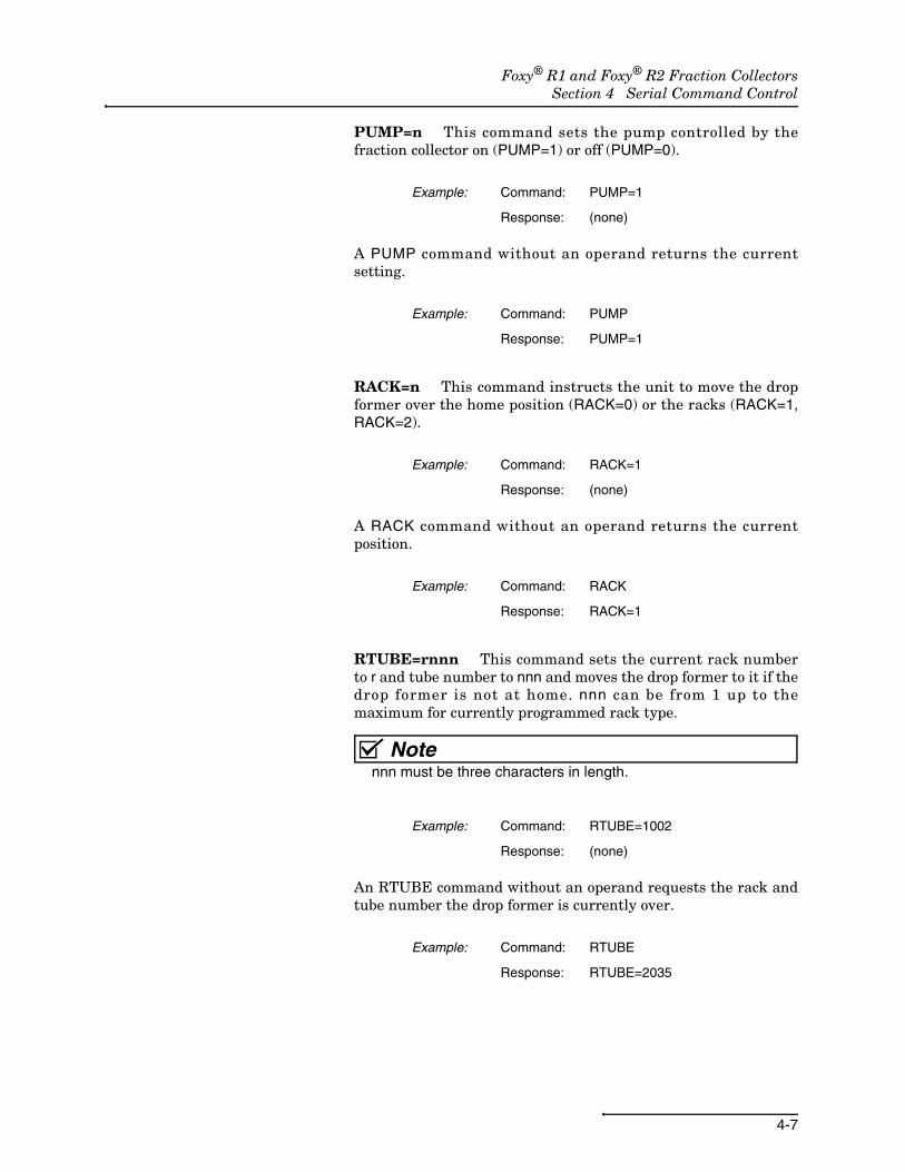
Foxy® R1 and Foxy® R2 Fraction CollectorsSection 4 Serial Command Control
4-7
PUMP=n This command sets the pump controlled by thefraction collector on (PUMP=1) or off (PUMP=0).
A PUMP command without an operand returns the currentsetting.
RACK=n This command instructs the unit to move the dropformer over the home position (RACK=0) or the racks (RACK=1,RACK=2).
A RACK command without an operand returns the currentposition.
RTUBE=rnnn This command sets the current rack numberto r and tube number to nnn and moves the drop former to it if thedrop former is not at home. nnn can be from 1 up to themaximum for currently programmed rack type.
Notennn must be three characters in length.
An RTUBE command without an operand requests the rack andtube number the drop former is currently over.
Example: Command: PUMP=1
Response: (none)
Example: Command: PUMP
Response: PUMP=1
Example: Command: RACK=1
Response: (none)
Example: Command: RACK
Response: RACK=1
Example: Command: RTUBE=1002
Response: (none)
Example: Command: RTUBE
Response: RTUBE=2035
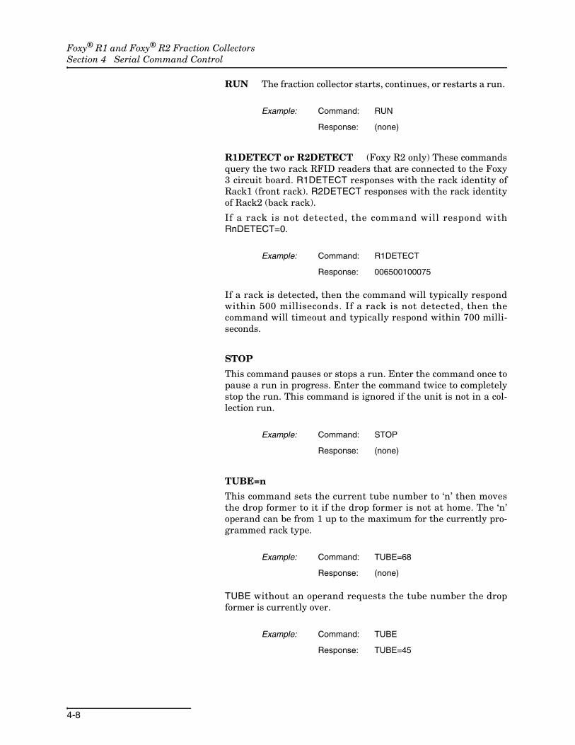
Foxy® R1 and Foxy® R2 Fraction CollectorsSection 4 Serial Command Control
4-8
RUN The fraction collector starts, continues, or restarts a run.
R1DETECT or R2DETECT (Foxy R2 only) These commandsquery the two rack RFID readers that are connected to the Foxy3 circuit board. R1DETECT responses with the rack identity ofRack1 (front rack). R2DETECT responses with the rack identityof Rack2 (back rack).
If a rack is not detected, the command will respond withRnDETECT=0.
If a rack is detected, then the command will typically respondwithin 500 milliseconds. If a rack is not detected, then thecommand will timeout and typically respond within 700 milli-seconds.
STOP
This command pauses or stops a run. Enter the command once topause a run in progress. Enter the command twice to completelystop the run. This command is ignored if the unit is not in a col-lection run.
TUBE=n
This command sets the current tube number to ‘n’ then movesthe drop former to it if the drop former is not at home. The ‘n’operand can be from 1 up to the maximum for the currently pro-grammed rack type.
TUBE without an operand requests the tube number the dropformer is currently over.
Example: Command: RUN
Response: (none)
Example: Command: R1DETECT
Response: 006500100075
Example: Command: STOP
Response: (none)
Example: Command: TUBE=68
Response: (none)
Example: Command: TUBE
Response: TUBE=45

Foxy® R1 and Foxy® R2 Fraction CollectorsSection 4 Serial Command Control
4-9
VALVE=n This command turns the valve on or off. SettingVALVE=0 will cause the flow to the drop former to be diverted towaste with a three-way valve. Setting VALVE=1 will allow flow tothe drop former.
The VALVE command without an operand returns the currentvalve state.
Unsupported Immediate Control CommandsThe following serial commands are not supported by the fractioncollector.
• GRADIENT=n
• OSTATE=n
• OUTPUT=n
• PSPEED=nThese commands were available for earlier fraction collectormodels. Do not use them with the fraction collectors.
4.5.3 Programming Commands
DEFAULT=1 This command clears the current program todefaults.
NoteTo minimize accidental clearing, the characters "=1" arerequired.
DELAY=n This command sets the flow delay of the currentprogram. If FTYPE=1 or 2 (fraction by time or drops), then n=0 to359999 seconds. If FTYPE=3 (fraction by external counts), thenn=0 to 999999 counts. For example, FTYPE=1;DELAY=102 sets aflow delay of 1 minute 42 seconds.
The DELAY command without an operand returns the currentsetting.
Example: Command: VALVE=1
Response: (none)
Example: Command: VALVE
Response: VALVE=1
Example: Command: DEFAULT=1
Response: (none)
Example: Command: DELAY=120
Response: (none)

Foxy® R1 and Foxy® R2 Fraction CollectorsSection 4 Serial Command Control
4-10
FSIZE=n This command sets the fraction size for the currentprogram. If FTYPE=1 (fraction by time), n=1 to 359999; ifFTYPE=2 or 3 (fraction by drops or external counts), n=0 to999999.
The FSIZE command without an operand returns the currentsetting.
FTYPE=n This command sets the fraction type of the currentprogram. Choices are Fraction by Time (FTYPE=1), Fraction byDrops (FTYPE=2), or Fraction by External counts (FTYPE=3).
The FTYPE command without an operand returns the currentsetting.
LAST=n This command sets the last tube of the currentprogram. Choices are n=1 to n=maximum number of tubes forprogrammed rack type.
The LAST command without an operand returns the currentsetting.
Example: Command: DELAY
Response: DELAY=120
Example: Command: FSIZE=23
Response: (none)
Example: Command: FSIZE
Response: FSIZE=23
Example: Command: FTYPE=3
Response: (none)
Example: Command: FTYPE
Response: FTYPE=3
Example: Command: LAST=10
Response: (none)
Example: Command: LAST
Response: LAST=10

Foxy® R1 and Foxy® R2 Fraction CollectorsSection 4 Serial Command Control
4-11
NONPEAK=n This command sets the non-peak/windowaction of the current program. Choices are Collect (n=1), Divert(n=2), or Drain (n=3).
The NONPEAK command without an operand returns thecurrent setting.
PATTERN=n This command sets the rack filling pattern ofthe current program. Choices are Standard (n=1) or Left-to-rightonly (n=2).
The PATTERN command without an operand returns the currentsetting.
PROGRAM=n
This command sets the current program number. Choices aren=1 to 8.
The PROGRAM command without an operand returns thecurrent setting.
Example: Command: NONPEAK=3
Response: (none)
Example: Command: NONPEAK
Response: NONPEAK=3
Example: Command: PATTERN=1
Response: (none)
Example: Command: PATTERN
Response: PATTERN=1
Example: Command: PROGRAM=8
Response: (none)
Example: Command: PROGRAM
Response: PROGRAM=8

Foxy® R1 and Foxy® R2 Fraction CollectorsSection 4 Serial Command Control
4-12
RANGE=n
This command sets the detector signal voltage range of thecurrent program. The choices are:
• n=1 1 Volt
• n=2 100 mV
• n=3 10 mV
• n=4 External detector
The RANGE command without an operand returns the currentsetting.
RESTART=n This command sets the restart action of thecurrent program.
Choices are:
• n=1 None
• n=2 Inject, Overlay
• n=3 Inject, Skip Tube
• n=4 Time, Overlay
• n=5 Time, Skip Tube
• n=6 Inject, Next Tube
• n=7 Time, Next Tube
The RESTART command without an operand returns the currentsetting.
RSTIME=n This command sets the restart time (n=0 to359999 seconds) of the current program.
Example: Command: RANGE=2
Response: (none)
Example: Command: RANGE
Response: RANGE=2
Example: Command: RESTART=5
Response: (none)
Example: Command: RESTART
Response: RESTART=5
Example: Command: RSTIME=600
Response: (none)

Foxy® R1 and Foxy® R2 Fraction CollectorsSection 4 Serial Command Control
4-13
The RSTIME command without an operand returns the currentsetting.
R1LAST=n or R2LAST=n These commands set the last tubefor Rack1 or Rack2. Choices are n=1 to n=maximum number oftubes for programmed rack type.
The R1LAST or R2LAST command without an operand returnsthe current setting.
R1TYPE=n or R2TYPE=n These commands set the racktype of the current program. Choices are:
• n=0 none
• n=1 12/13 mm tubes
• n=2 16 mm tubes
• n=3 18 mm tubes
• n=4 17 mm vials
• n=5 25/28 mm vials
• n=6 1.5 mL microcentrifuge tubes
• n=7 36 funnel prep. rack
• n=8 Bottles
• n=9 Single Beaker
• n=10 Microplates, 96 well × 2
• n=11 Microplates, 96 well × 6
• n=12 26 funnel prep. rack
The RTYPE command without an operand returns the currentsetting.
Example: Command: RSTIME
Response: RSTIME=5000
Example: Command: R2LAST=10
Response: (none)
Example: Command: R2LAST
Response: R2LAST=10
Example: Command: RTYPE=5
Response: (none)
Example: Command: RTYPE
Response: RTYPE=5

Foxy® R1 and Foxy® R2 Fraction CollectorsSection 4 Serial Command Control
4-14
THRESHOLD=n This command sets the peak threshold (n=0[none] to 100)% of the current program.
The THRESHOLD command without an operand returns thecurrent setting.
WIDTH=n This command sets the peak detection width of thecurrent program. Choices are:
• n=1 5 seconds
• n=2 15 seconds
• n=3 30 seconds
• n=4 1 minute
• n=5 2 minutes
• n=6 4 minutes
• n=7 8 minutes
• n=8 16 minutes
• n=9 32 minutes
• n=10 1 hour
• n=11 No slope detection
The WIDTH command without an operand returns the currentsetting.
WINDOW=n
The maximum number of windows is one. This command setswhich window number (n=1) will be used for the WSTART andWEND commands that follow.
Example: Command: THRESHOLD=10
Response: (none)
Example: Command: THRESHOLD
Response: THRESHOLD=10
Example: Command: WIDTH=2
Response: (none)
Example: Command: WIDTH
Response: WIDTH=2
Example: Command: WINDOW=1
Response: (none)

Foxy® R1 and Foxy® R2 Fraction CollectorsSection 4 Serial Command Control
4-15
The WINDOW command without an operand returns the currentsetting.
WSTART=n This command sets the window start time (n=0to 359999 seconds) of the currently selected window.
The WSTART command without an operand returns the currentsetting.
WEND=n This command sets the window end time (n=0 to359999 seconds) of the currently selected window.
The WEND command without an operand returns the currentsetting.
UPLOAD The unit responds to this command with thecurrent program settings, one line at a time. The UPLOADcommand must be sent for each line in the program untilNOTE=END is received from the unit. Settings are in the form ofcommands allowing them to be sent back to the unit to restore aprogram. All settings are sent, even if they are not relevant tothe way the program is currently set.
Example: Command: WINDOW
Response: WINDOW=1
Example: Command: WSTART=36000
Response: (none)
Example: Command: WSTART
Response: WSTART=240
Example: Command: WEND=60
Response: (none)
Example: Command: WEND
Response: WEND=240
Example: Command: UPLOAD
Response: PROGRAM=1
Command: UPLOAD
Response: DELAY=0

Foxy® R1 and Foxy® R2 Fraction CollectorsSection 4 Serial Command Control
4-16
UPLOAD=n This command chooses which program line (n=0to 71) is to be sent next.
UPLOAD=–1 This command responds with the commandstrings for the entire current program immediately.
Unsupported Programming CommandsThe following serial commands are not supported by the fractioncollector.
• ESTATE=n
• ETIME=n
• ETYPE=n
• EVENT=n
• LIST
• PTYPEThese commands were available for earlier fraction collectormodels. Do not use them with the Foxy R1 and R2 fraction col-lectors.
Example: Command: UPLOAD=0
Response: (none)
Example: Command: UPLOAD=–1
Response: NOTE=PROGRAM 3PTYPE=4LAST=144PATERN=1FTYPE=1FSIZE=1DELAY=0RANGE=1THRESHOLD=0WIDTH=11NONPEAK=3RESTART=2WINDOW=1; WSTART=0; WEND=60NOTE=Config: Pump off=0, Only rack=11NOTE=Pattern=3, Peak det. =5, Motor=5NOTE=Cal: 0mV=32768, 1V=58982,NOTE=100mV=58982, 10mV=35389,NOTE=Time=749, VREF=500, Bklash=0NOTE=FLLR=128, FLFB=128, FRLR=128NOTE=FRFB=128, BLLR=128, BLFB=128NOTE=END

Foxy® R1 and Foxy® R2 Fraction CollectorsSection 4 Serial Command Control
4-17
4.5.4 Problem Responses The fraction collector will respond with a PROBLEM=<type>message should the command fail. The following types may bereported.
IMPROPER MODE The program values cannot be changedwhile a run is in progress.
NoteRUN and STOP cannot be executed while in manual control.
INVALID COMMAND One of three situations could causethis response:
• An unknown command has been entered, usually a typographical error.
• An operand has been sent for a command that does not require one.
• An operand is missing for a command that requires one.
INVALID OPERAND The operand value is out of range orunsupported.
LOCAL MODE The unit must be in the remote mode to doanything other than read values.

Foxy® R1 and Foxy® R2 Fraction CollectorsSection 4 Serial Command Control
4-18

5-1
Foxy® R1 and Foxy® R2 Fraction Collectors
Section 5 Maintenance
5.1 Introduction The fraction collector is designed for years of use in typical labo-ratory applications. The recommended maintenance tasks pri-marily address the fluid path, drains, and the fraction collectorexterior. These tasks should be performed as needed to ensurethe optimum performance of items such as the diverter valve anddrop counter, as well as protect the exterior finish. Itsmechanical parts do not require periodic adjustment or lubri-cation.
The fraction collector does not contain user-serviceable parts.Should your instrument require service, refer to section 5.3 forassistance.
5.2 Maintenance Perform the following tasks as necessary:
• Tubing Inspection, section 5.2.1
• Rack and Drip Tray Cleaning, section 5.2.2
• General Cleaning, section 5.2.3
• Fluid Path Cleaning, 5.2.4
• Drop Counter Cleaning, 5.2.5
WARNINGIf collecting fluids that can produce flammable vapors, perform the Tubing Inspection (5.2.1), and the Rack and Drip Tray Cleaning (5.2.2) at least monthly.
5.2.1 Tubing Inspection
WARNINGRisk of fire or equipment damage. Faulty tubing, fittings, and drains may allow organic solvents to pool in unsafe areas, creating a potential for dangerous levels of flammable vapors. Improper draining may damage the instrument’s internal components.
If the fraction collector is used with solvents that produce flam-mable vapors, perform a tubing inspection monthly:
1. Visually inspect the diverter valve inlet and waste lines. The tubing must be free of any damage, kinks, or deterio-ration. Fittings should show no signs of leaks.
2. Visually inspect the drip tray drain tubing. The tubing should be free of any damage, kinks, deterioration, or obstructions.

Foxy® R1 and Foxy® R2 Fraction CollectorsSection 5 Maintenance
5-2
Correct any deficiencies before returning the instrument to oper-ation.
5.2.2 Collection Rack and Drip Tray Cleaning
WARNINGRisk of fire or equipment damage. Dirty collection racks and drip tray might inhibit their conductive properties. The racks and tray must be kept clean to dissipate static electricity.
Collection tube racks and drip tray should be kept clean so thatthey dissipate static electricity. Dirt, film, or coatings mightprevent their ability to dissipate static electricity. To avoidproblems that possibly result from an electrostatic discharge,clean the racks and tray monthly. Use distilled water with a milddetergent. For tougher stains, use isopropyl alcohol.
The drip tray can be removed for thorough cleaning. It is held inplace by pins. First remove the collection racks and any draintubes. Pry the corners of the drip tray loose with your fingers.After loosening all four corners, lift the drip tray up and off of theinstrument case. Clean the drip tray with mild detergent.
To replace the drip tray, place the tray on the instrument,aligning the drain with its hole. Press down on the tray firmly toseat it onto the pins.
5.2.3 Exterior Cleaning To clean the exterior surfaces, use a cleaning cloth dampenedwith a mixture of distilled water and a mild detergent. Use iso-propyl alcohol for tougher stains.
On printed areas such as labels, avoid rubbing vigorously orusing aggressive solvents like acetone. Each will ruin the printedtext.
Quickly clean up any aggressive solvents spilled on the exteriorsurfaces. The paint protects the underlying metal from corrosion.Aggressive solvents might also damage the plastic covers whichprotect internal components.
CAUTIONDo not immerse the instrument in a water bath or subject it to aliquid spray. The instrument is not watertight and these actionscould damage the internal electronics.
5.2.4 Fluid Path Cleaning Precipitates, crystals, oils, etc., can degrade the performance ofthe fluid lines, as well as the fraction collector’s diverter valveand drop counter operation. If you experience problems with thefluid path or the diverter valve outlet, flush the fluid path withmiscible solvent or buffer.
Difficult obstructions may require stronger solvents or buffers asa cleaning fluid. Consider allowing the cleaning fluid to remainin the fluid path overnight.

Foxy® R1 and Foxy® R2 Fraction CollectorsSection 5 Maintenance
5-3
If problems occur frequently, consider pumping a cleaning fluidthrough the path as final step in each collection routine.
5.2.5 Drop Counter Cleaning
The drop counter is a photosensor device at the outlet of thediverter valve. This device uses a glass sleeve to protect the elec-tronic components. If the performance of the drop counterdegrades, the glass sleeve should be cleaned.
To clean the glass sleeve:
1. Place the fraction collector in Standby and remove the AC mains power cord.
2. Remove the collection racks.
3. Carefully unscrew the black retaining ring located under the diverter valve. The glass sleeve rests inside the retain-ing ring.
Figure 5-1 Retaining ring for the drop counter’s glass sleeve
4. Clean the glass sleeve with a mixture of distilled water and a mild detergent. Use isopropyl alcohol for tougher stains. Alternatively, the tube can be placed in an ultrasonic bath.
CAUTIONUse care to avoid scratching or otherwise damaging the glasstube.
5. Place the cleaned glass sleeve back into the retaining ring and thread the ring back into the diverter valve.
6. Replace the collection racks, connect the AC mains power cord, and return the fraction collector to operation.
CAUTIONOperating the fraction collector without the glass sleeve maydamage electronic components inside the diverter valveassembly. Never operate the fraction collector without theglass sleeve.
Retaining ring
Glass sleeve
Foxy® R1 and Foxy® R2 Fraction CollectorsSection 5 Maintenance
5-4
5.3 Service
WARNINGRisk of serious personal injury or equipment damage. The fraction collector does not contain user-serviceable parts. Service panels and cover should only be removed by trained personnel.
Service problems often can be resolved by telephone or E-mail.US customers can receive support by contacting the factory Tech-nical Service department. Contact information can be found onthe Foreword and Warranty pages at the front and back of thismanual. If you contact the factory by E-mail, please include theserial number and all relevant information regarding the diffi-culty you are experiencing with the instrument.
Customers outside of the US should contact their Teledyne Iscodealer for service support. Customers can find their regionaldealer by visiting the Teledyne Isco Web site:
http://www.isco.com/quick/replookup.asp
5.4 Instrument Returns Please contact the Service Department before returning theinstrument to the factory for repair. Return instructions can befound on the Foreword and Warranty pages at the front and backof this manual.
5.4.1 How to Ship Returns Before packing the instrument, make sure all parts andhardware are in their proper places. Wrap the instrument inheavy paper or put it in a plastic bag for extra protection. If at allpossible, pack the instrument in its original shipping containerwith the original packing material. If the original shipping con-tainer is not available, place the instrument in a strong card-board box at least six inches larger in all three dimensions thanthe instrument itself. Fill the box equally around the instrumentwith a resilient packing material, such as shredded paper,bubble pack, expanded foam, etc. Seal the box with strappingtape or other suitable shipping tape and ship it to the returnaddress listed on the warranty page. The warranty pagedescribes the conditions under which Teledyne Isco will paysurface shipping costs for returns.
It is very important that the instrument be well-packaged forshipment and fully insured. Damage claims must be conductedbetween you and the carrier. Damage in shipment due to inade-quate packing can delay the repair and return of the instrumentto you.

A-1
Foxy® R1 and Foxy® R2 Fraction Collectors
Appendix A Icon Glossary and Menu Charts
A.1 Touch Screen Icon Glossary
Table A-1 describes the fraction collector display icons.
Table A-1 Touch screen display icons
Icon Description
Select the Configuration Tools icon to configure the collection racks, communication settings, and injection overlay settings.
Select the Folder icon to open a screen from which you can view or modify the current selec-tion.
Touch the Diverter Valve Position icons to control the position of the diverter valve. When the arrow points to the tube the valve is set to collect fluids in tubes. When the arrow points to the waste can the valve is set to route fluids to waste.
Touch the Next Tube icon to advance the drop former to the next tube position.
Touch the Play icon from the main menu to start operation.
Touch the Pause icon during operation to sus-pend tube advances. While paused, the Pump Pause output signal is active to disable an exter-nal pump.
Touch the Stop icon to halt operation. The drop former will return to the home position.
Touch the Standby/On icon to toggle the fraction collector between these modes.

Foxy® R1 and Foxy® R2 Fraction CollectorsAppendix A Icon Glossary and Menu Charts
A-2
Touch the Enter icon to accept the current set-tings and return to the previous screen.
Touch the Rack icon to open a screen from which you can select the rack type and collection pat-tern, and calibrate the drop former position.
The Tube Advance Speed icon allows you to access a screen from which you can set the speed of the tube advance motion. From the tube advance speed screen, touch this icon to speed up the movement.
Touch the Slow icon to slow the tube change movement.
This icon indicates the tube advance speed set-ting. The speed setting ranges from 1 (slowest) to 5 (fastest).
Touch the Calibrate icon to open a screen from which you can adjust the drop former position.
When calibrating the arm, touch the First Tube Position icon to move the drop former over the first tube. The drop former will move to the first tube position for the current rack configuration.
When calibrating the arm, touch the Last Tube Position icon to move the drop former over the last tube. The drop former will move to the last tube position for the current rack configuration. On two rack fraction collectors the last tube posi-tion is on the second rack.
The Arrow icons perform several functions. In some screens, the up and down arrows incre-ment and decrement alphanumeric values. In other screens, the arrows move the cursor posi-tion. In the calibrate mode, the arrow icons finely calibrate the drop former position.
Touch the Collection Pattern icon to toggle between left-to-right and serpentine patterns.
Touch the Serial Port icon to open a screen from which you can configure the serial communica-tion settings.
Touch the Ethernet Port icon to open a screen from which you can configure TCP/IP communi-cation settings and view the MAC address.
Table A-1 Touch screen display icons (Continued)
Icon Description

Foxy® R1 and Foxy® R2 Fraction CollectorsAppendix A Icon Glossary and Menu Charts
A-3
Touch the Inject icon to open a screen from which you can select the restart action for each injection.
Restarts can be initiated by a user-specified Time or an Inject signal from an external device. When using one of the Inject options, the fraction collec-tor waits for the first restart event before starting the method. The touch screen Play icon will alter-nate with the Inject icon while waiting. After the injection, touch the Play icon to continue with the method. Timed restarts occur without interven-tion.
When a restart occurs, the collection pattern can return to the first tube of the previous run to Over-lay multiple fractions from a repeated sample. Alternatively, a restart can start at the Next tube, or Skip a tube to separate the runs.
Touch the Pump Control icon to access the set-tings to control the output at pin 2 of the Pump connector. This signal can be used to pause the pump operation during tube advances.
The icon with the “1” (left) indicates that the frac-tion collector will not send a pause signal from pin 2. In this state, the external pump will continue to operate during tube changes. The icon with the “0” indicates that the fraction collector will send a pause signal from pin 2.
Touch the Analog Peak setting icon to view a list of voltage ranges for the peak input. When using this feature, set the analog peak voltage scale to the range of the detector signal.
Touch the Information icon to display Model num-ber and hardware/firmware revisions.
Touch the Drop icon to collect fractions based on the number of drops collected. Touching this icon opens a screen from which you can set the delay volume (as a number of drops) and the number of drops to collect before performing a tube advance. If selected, the display shows a border around this icon.
Touch the Time icon to collect fractions based on time. Touching this icon opens a screen from which you can set the delay volume (as a time interval) and the time duration of each fraction. If selected, the display shows a border around this icon.
Touch the Volume icon to collect fractions based on an external pump volume count. Touching this icon opens a screen from which you can set the fraction and delay volumes as a number of pump counts. If selected, the display shows a border around this icon.
Table A-1 Touch screen display icons (Continued)
Icon Description

Foxy® R1 and Foxy® R2 Fraction CollectorsAppendix A Icon Glossary and Menu Charts
A-4
Each touch of the Volume Select icon toggles between volume setting modes. The current selection is indicated by the surrounding border. When the hourglass (left) is selected, enter the delay volume. When the tube (right) is selected, enter the fraction size. The units for each setting reflect the selected Time, Drop, or Volume, frac-tion collection mode.
Touch the Threshold Peak Detection icon to con-figure the threshold settings. A border around this icon indicates that threshold peak detection is enabled. When editing the threshold settings you can touch the icon again to toggle between col-lection modes. The left icon indicates that only peak fluids will be collected; non-peak fluids are diverted to waste. The right icon indicates that peak and nonpeak fluids will be collected.
Threshold detection monitors the percentage of an analog input signal. The threshold condition is true when the input signal exceeds a user-set value. However, the peak state may or may not be true depending on the threshold detection options.
Touch the Threshold Detection Options icons to toggle through the detection modes. The top icon indicates that threshold peak detection is OFF. The middle Union icon indicates that threshold peak detection is enabled. If the threshold value is exceeded, the peak state will be true regard-less of any other detection mode (a logical OR). The bottom Intersection icon indicates that peak detection is enabled. If the threshold value is exceeded, the peak state is true only when other enabled detection conditions are met (a logical AND).
Touch the Peak Width Detection icon to configure the peak width settings. A border around this icon indicates that peak width detection is enabled. When editing the peak width settings you can touch the icon again to toggle between collection modes. The left icon indicates that only peak flu-ids will be collected; non-peak fluids are diverted to waste. The right icon indicates that peak and nonpeak fluids will be collected.
In this detection mode, the system uses a user-specified peak width value and an algorithm to determine a range of possible input signal slopes. A peak width condition is true when the analog input signal rises at a rate within this range. However, the peak state may or may not be true depending on the peak width detection options.
Table A-1 Touch screen display icons (Continued)
Icon Description

Foxy® R1 and Foxy® R2 Fraction CollectorsAppendix A Icon Glossary and Menu Charts
A-5
Touch the Peak Width Detection Options icons to toggle through the detection modes. The top icon indicates that peak width detection is OFF. The middle Union icon indicates that peak width detection is enabled. If the slope of the input sig-nal indicates a peak, the peak state will be true regardless of any other detection mode (a logical OR). The bottom Intersection icon indicates that peak width detection is enabled. If the slope of the input signal indicates a peak, the peak state is true only when other enabled detection condi-tions are met (a logical AND).
Touch the Time Window icon to combine peak detection with a time window. A border around this icon indicates that a time window is pro-grammed and enabled.
Touch the Time Window Options icons to toggle modes. The left icon indicates that the Time Win-dow mode is OFF. The right Intersection icon indicates that a time window is enabled. If a threshold or peak width detection condition is true, and the time window condition is true, the peak state is also true (a logical AND).
Each touch of the Time Window Start/Stop icon toggles between setting modes. When the start time (left) is selected, enter the window start time. When the stop time (right) is selected, enter the window stop time. Start and stop times are rela-tive to the time you press the Run button to start operation.
The computer icon indicates that a remote device is connected to the fraction collector. When under remote control, all run-time controls may also be accessed from the touch screen display. how-ever, programming and configuration settings cannot be modified.
Touch this icon to terminate the remote connec-tion and operate the fraction collector from the touch screen display. This will return you to the main menu from which you can also access the configuration and programming menus.
Table A-1 Touch screen display icons (Continued)
Icon Description

Foxy® R1 and Foxy® R2 Fraction CollectorsAppendix A Icon Glossary and Menu Charts
A-6
A.2 Touch Screen Menu Flow Charts
Figures A-1 through A-4 illustrate the fraction collector menus.
Figure A-1 Configuration settings
Timed &
1200240048009600
192003840057600
115200
100 mV.
external
None Inject & overlayInject & next Inject & skip
99 h59 m59 s
1000 mV.
10 mV.

Foxy® R1 and Foxy® R2 Fraction CollectorsAppendix A Icon Glossary and Menu Charts
A-7
Figure A-2 Configuration settings, continued
None 12mmx14413mmx14416mmx10018mm x72MiniVial25mm x3628mm x36
IP
1.202 192.168.
IP MASK
255. 0 255.255.
MAC
00:00:0000:17:8b
SERIES: 3870-010
REV x
FIRMWARE
n.nn.nn
13mmx144
none
IP MASK
255. 0 255.255.
IP
1.202 192.168.

Foxy® R1 and Foxy® R2 Fraction CollectorsAppendix A Icon Glossary and Menu Charts
A-8
Figure A-3 Programming displays for the current method
__1 20s__m__h
_32 __h
20s
__m
__h
_0s
20m
0h
0s
1m_10%
To Fig. A-4

Foxy® R1 and Foxy® R2 Fraction CollectorsAppendix A Icon Glossary and Menu Charts
A-9
Figure A-4 Saved method recall and method name editing
Method A
16mmTubeMethod DDefaultEDefaultFDefaultGDefaultH
Method AMethod B
From Fig. A-3

Foxy® R1 and Foxy® R2 Fraction CollectorsAppendix A Icon Glossary and Menu Charts
A-10

B-1
Foxy® R1 and Foxy® R2 Fraction Collectors
Appendix B Replacement Parts Listings
Replacement parts are called out in the following pages. Refer tothe call-out in the adjacent table to determine the part numberfor the item.
Replacement parts can be purchased by contacting TeledyneIsco’s Customer Service Department.
Teledyne Isco, Inc.Customer Service DepartmentP.O. Box 82531Lincoln, NE 68501 USA
Phone: (800) 228-4373(402) 464-0231
FAX: (402) 465-3022
E-mail: [email protected]

Foxy® R1 and Foxy® R2 Fraction CollectorsAppendix B Replacement Parts Listings
B-2

Foxy® R1 and Foxy® R2 Fraction CollectorsAppendix B Replacement Parts Listings
B-3

Foxy® R1 and Foxy® R2 Fraction CollectorsAppendix B Replacement Parts Listings
B-4

Foxy® R1 and Foxy® R2 Fraction CollectorsAppendix B Replacement Parts Listings
B-5

Foxy® R1 and Foxy® R2 Fraction CollectorsAppendix B Replacement Parts Listings
B-6

Foxy® R1 and Foxy® R2 Fraction CollectorsAppendix B Replacement Parts Listings
B-7

Foxy® R1 and Foxy® R2 Fraction CollectorsAppendix B Replacement Parts Listings
B-8

Foxy® R1 and Foxy® R2 Fraction CollectorsAppendix B Replacement Parts Listings
B-9

Foxy® R1 and Foxy® R2 Fraction CollectorsAppendix B Replacement Parts Listings
B-10

Foxy® R1 and Foxy® R2 Fraction CollectorsAppendix B Replacement Parts Listings
B-11

Foxy® R1 and Foxy® R2 Fraction CollectorsAppendix B Replacement Parts Listings
B-12

Foxy® R1 and Foxy® R2 Fraction CollectorsAppendix B Replacement Parts Listings
B-13

Foxy® R1 and Foxy® R2 Fraction CollectorsAppendix B Replacement Parts Listings
B-14

Foxy® R1 and Foxy® R2 Fraction CollectorsAppendix B Replacement Parts Listings
B-15

Foxy® R1 and Foxy® R2 Fraction CollectorsAppendix B Replacement Parts Listings
B-16

Foxy® R1 and Foxy® R2 Fraction CollectorsAppendix B Replacement Parts Listings
B-17

Foxy® R1 and Foxy® R2 Fraction CollectorsAppendix B Replacement Parts Listings
B-18

Foxy® R1 and Foxy® R2 Fraction CollectorsAppendix B Replacement Parts Listings
B-19

Foxy® R1 and Foxy® R2 Fraction CollectorsAppendix B Replacement Parts Listings
B-20

Foxy® R1 and Foxy® R2 Fraction CollectorsAppendix B Replacement Parts Listings
B-21
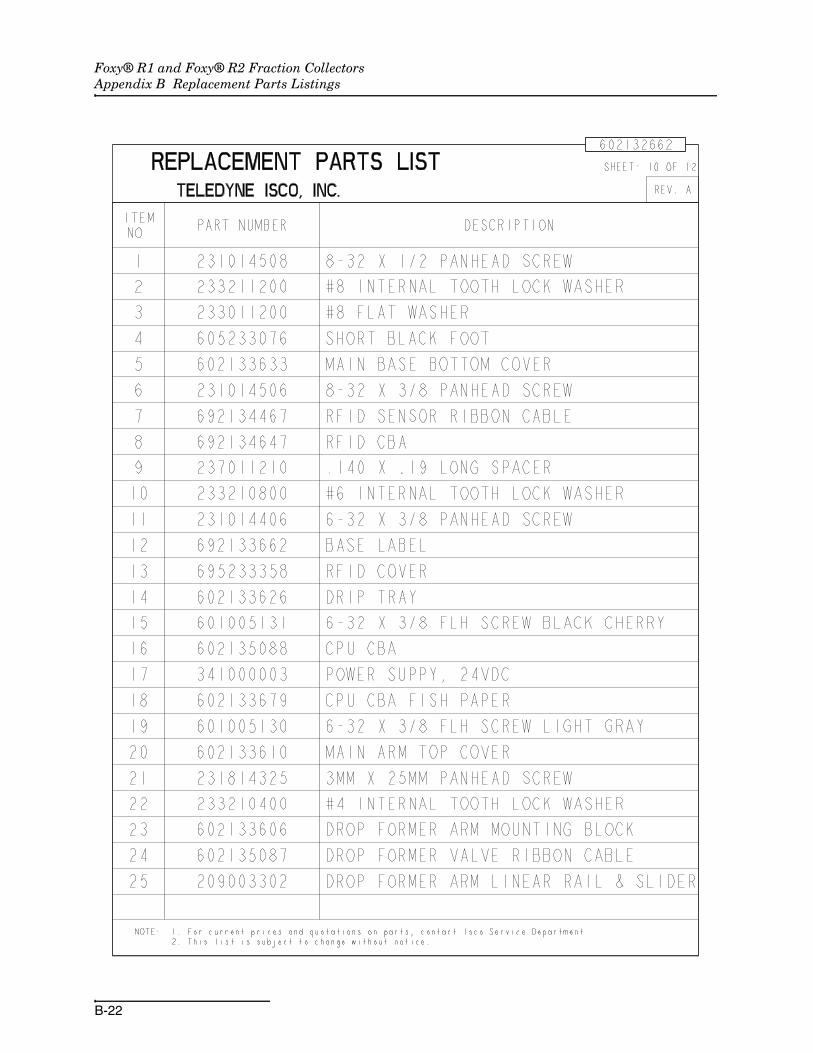
Foxy® R1 and Foxy® R2 Fraction CollectorsAppendix B Replacement Parts Listings
B-22

Foxy® R1 and Foxy® R2 Fraction CollectorsAppendix B Replacement Parts Listings
B-23

Foxy® R1 and Foxy® R2 Fraction CollectorsAppendix B Replacement Parts Listings
B-24

Index-1
Foxy® R1 and Foxy® R2 Fraction Collectors
Index
AAC power cord, 2-2addresses, IP and MAC, 3-5AND, combined peak detection, 3-16, 3-18,
3-19applications, typical, 1-6
Ccables
CAT5, 4-1Isco detector, 1-9Isco pump, 1-9non-Isco detector, 1-10non-Isco pump, 1-9
calibration, drop former position, 3-4CAT5 cable, 4-1checklist, installation qualification (IQ), 2-11claims, damage, 2-1, 5-4cleaning
drip tray and racks, 5-2drop counter, 5-3exterior, 5-2fluid path, 5-2
collection rackcleaning, 5-2grounding, 2-9installation, 2-8part numbers, 1-3
collection tube pattern, 3-4collection tube volumes
by drop counts, 3-12by pump counts, 3-14by time intervals, 3-13
commands, serialimmediate control, 4-6miscellaneous, 4-2problem responses, 4-17programming, 4-9syntax, 4-2
communicationsethernet, 4-1RS232 serial, 4-1
configuration settings, 3-2connections
diverter valve, 2-5drip tray drain tubing, 2-7electrical, 1-7 to 1-10fluid, 2-5
connectorsAC mains power, 1-7detector, 1-8ethernet, 1-7pump, 1-8rear panel diagram, 1-7serial (RS232), 1-9
Ddamage claims, 2-1, 5-4delay volume
calculating, 3-12compensation, 1-6
detector cableIsco, 1-9non-Isco, 1-10rear panel connector, 1-8
dimensions, physical, 1-5diverter valve
fluid connections, 2-5height adjustment, 2-2, 2-10
drip traycleaning, 5-2drain tubing connection, 2-7removal, 5-2
drop countercleaning, 5-3glass sleeve, 5-3
drop countinggeneral, 1-2settings, 3-11
drop former calibration, 3-4
Eerror messages, 4-17ethernet
communications, 4-1rear panel connector, 1-7settings, 3-5
external peak detection, 3-9
Ffactory service, 5-4features, 1-4ferrules, 2-6firmware version, 3-9fittings, swaged, 2-6flow delay, when using pump counts, 3-15

Foxy® R1 and Foxy® R2 Fraction CollectorsIndex
Index-2
flow delays, 3-12flow rate, maximum, 1-6fluid path cleaning, 5-2fluids, collect or divert, 3-16, 3-18funnel racks, 1-4
Gglass sleeve, 5-3
Hhardware version, 3-9
Iillustrated parts breakdown, B-1injection options, 3-6input signals
connector pins, 1-7 to 1-10peak options, 1-2peak voltage setting, 3-9specifications, 1-6
inspectionpreliminary, 2-1rack grounding, 2-9tubing, 5-1
installation qualification (IQ) checklist, 2-11intersection (Venn diagram symbol), 3-19IP address and mask, 3-5
LLabVIEW, 4-1local mode, 3-1, 4-2, 4-4logical operators (AND, OR), 3-16, 3-18, 3-19lubrication, not required, 5-1
Mmain menu, 2-3, 3-1mains power cord, 2-2materials, wetted, 1-6menus
configuration, 3-3drop counting, 3-11main, 2-3, 3-1method editing, 2-4method selection, 3-10method settings, 3-10rack settings, 3-3renaming a method, 3-11threshold peak detection, 3-16time intervals, 3-13time window, 3-20time-based fractions, 2-4volume (pump count) settings, 3-14
methodselection menu, 2-3, 3-10settings, 3-10
modecomputer icon, 3-1local, 4-4remote, 4-2, 4-4
Nnext tube option, injection or timed restarts, 3-8
OOR, combined peak detection, 3-16, 3-18, 3-19output signals
connector pins, 1-7 to 1-10pump control setting, 3-9specifications, 1-6
overlay tubes option, injection or timed restarts,3-7
Ppacking, 5-4parts, replacement, B-1pattern, collection tube, 3-4peak and waste fluids, 3-16, 3-18peak detection
combining threshold and peak width, 3-16,3-18, 3-19
external detector, 3-9peak width (slope), 3-17threshold, 3-15
peak input signalspecifications, 1-2
peak width (slope) detectiongeneral, 1-2ranges, 3-18settings, 3-17
physical dimensions, 1-5power cord, 2-2preliminary checkout, 2-1pump cable
Isco, 1-9non-Isco, 1-9rear panel connector, 1-8
pump control output settings, 3-9pump count settings, 3-14
Rrack
cleaning, 5-2configuration settings, 3-3grounding, 2-9installation, 2-8part numbers, 1-3RFID detection (Foxy R2), 2-8
remote mode, 3-1, 4-2, 4-4renaming a method, 3-11replacement parts, B-1restarts, 3-6returns, 5-4

Foxy® R1 and Foxy® R2 Fraction CollectorsIndex
Index-3
RFID, 2-8defined, 1-1racks and funnels, 1-4
RS232 serialcommunications, 4-1connector, 1-9settings, 3-5
Sserial (RS232)
communication settings, 3-5communications, 4-1connector, 1-9
serial commandsimmediate control, 4-6miscellaneous, 4-2problem responses, 4-17programming, 4-9syntax, 4-2
service, 5-4shipping, 5-4skip tube option, injection or timed restarts, 3-8slope detection - see peak width detectionspecifications, 1-5speed, tube advance, 3-4swaged fittings, 2-6syntax, serial commands, 4-2system control options, 1-6
TTCP/IP settings, 3-5telnet, 4-1temperature, operating, 1-6threshold detection
general, 1-2settings, 3-15
time intervalsgeneral, 1-2settings, 3-13
time windowgeneral, 1-2menu, 3-20settings, 3-20
timed restarts, 3-6tools, configuration, 3-2tube advance speed, 3-4tube height, maximum, 1-6tube volumes
by drop counts, 3-12by pump counts, 3-14by time intervals, 3-13
tubing inspection, 5-1
Uunion (Venn diagram symbol), 3-19unpacking, 2-1
VVenn diagrams, 3-16, 3-18, 3-19volume (pump count)
general, 1-2settings, 3-14
volumesby drop counts, 3-12by pump counts, 3-14by time intervals, 3-13
Wwarranty service, 5-4waste and peak fluids, 3-16, 3-18weight, 1-5wetted materials, 1-6window, time, 3-20

Foxy® R1 and Foxy® R2 Fraction CollectorsIndex
Index-4

CE Declaration of Conformity
DECLARATION OF CONFORMITY
Application of Council Directive: 2004/108/EC -The EMC Directive 2002/96/EC – The WEEE Directive73/23/EEC – The Low Voltage Directive
Manufacturer's Name: Teledyne Isco, Inc. Manufacturer's Address: 4700 Superior
Lincoln, Nebraska 68504-1398 USA P.O. Box 82531, Lincoln, NE 68501-2531
Equipment Type/Environment:
Phone: +1 (402) 464-0231 Facsimile: +1 (402) 465-3799
Laboratory Equipment for Light Industrial/Commercial Environments
Trade Name/Model No: Foxy R1, R2 Year of Issue: 2008
Standards to which Conformity is Declared: EN 61010-1 2nd edition Safety Requirements for Electrical Equipment for Measurement, Control, and Laboratory Use
EN 61326-1:2003 EMC Requirements for Electrical Equipment for Measurement, Control, and Laboratory Use
Standard Description Severity Applied Performance Criteria
EN61000-4-2 Electrostatic Discharge Level 2 - 4kV contact discharge Level 3 - 8kV air discharge
A
EN61000-4-3 Radiated RF Immunity 80 MHz to 1000MHz 80% AM at 1kHz Level 2 - 3V/m
A
EN61000-4-4 Electrical Fast Transient Level 2 - 1kV on AC lines A
EN61000-4-5 Surge on AC Lines Level 2 - 1kV common mode, Level 2 - 0.5KV differential mode
A
EN61000-4-6 Conducted RF on AC lines 150 kHz to 80 MHz, Level 1 - 1V rms, 80% modulated
A
EN61000-4-11 Voltage Dips/Interruptions 100% drop, 10ms A
CISPR11/ EN 55011
RF Emissions Group 1, Class A Industrial, Scientific, and Medical Equipment
The undersigned, hereby declares that the design of the equipment specified above conforms to the above Directive(s) and Standardsas of October 27, 2008.
USA Representative
William Foster Vice President of Engineering
60-2132-663

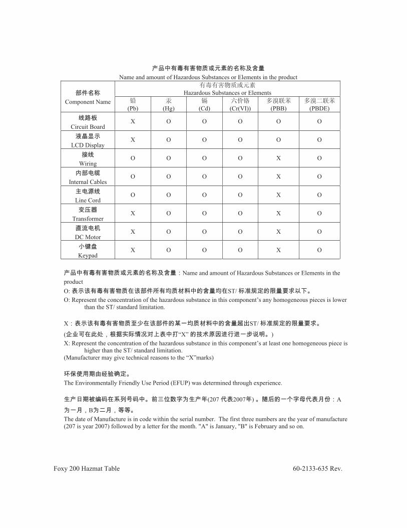
RoHS
Compliance Statements
Foxy 200 Hazmat Table 60-2133-635 Rev.
Name and amount of Hazardous Substances or Elements in the product
Hazardous Substances or Elements Component Name
(Pb) (Hg) (Cd) (Cr(VI)) (PBB) (PBDE)
Circuit Board X O O O O O
LCD Display X O O O O O
WiringO O O O X O
Internal Cables O O O O X O
Line Cord O O O O X O
Transformer X O O O X O
DC Motor X O O O X O
Keypad X O O O X O
Name and amount of Hazardous Substances or Elements in the productO: ST/O: Represent the concentration of the hazardous substance in this component’s any homogeneous pieces is lower
than the ST/ standard limitation.
X ST/
( “X” )X: Represent the concentration of the hazardous substance in this component’s at least one homogeneous piece is
higher than the ST/ standard limitation. (Manufacturer may give technical reasons to the “X”marks)
The Environmentally Friendly Use Period (EFUP) was determined through experience.
(207 2007 ) A
BThe date of Manufacture is in code within the serial number. The first three numbers are the year of manufacture (207 is year 2007) followed by a letter for the month. "A" is January, "B" is February and so on.


Warranty
Teledyne Isco One Year Limited Factory Service Warranty *
Teledyne Isco warrants covered products against failure due to faulty parts or workmanship for a period of one year (365 days) from their shipping date, or from the date of installation by an authorized Teledyne Isco Service Engineer, as may be appropriate.
This warranty does not cover loss, damage, or defects resulting from transportation between the customer’s facility and the repair facility.
Teledyne Isco specifically disclaims any warranty of merchantability or fitness for a particular purpose.During the warranty period, repairs,
replacements, and labor shall be provided at no charge. Teledyne Isco’s liability is strictly limited to repair and/or replacement, at Teledyne Isco’s sole discretion.
This warranty applies only to products sold under the Teledyne Isco trademark and is made in lieu of any other warranty, written or expressed.
Failure of expendable items (e.g., charts, ribbon, tubing, lamps, glassware, seals, filters, fittings, and wetted parts of valves), or from normal wear, accident, misuse, corrosion, or lack of proper maintenance, is not covered. Teledyne Isco assumes no liability for any consequential damages.
No items may be returned for warranty service without a return authorization number issued from Teledyne Isco.
The warrantor is Teledyne Isco, Inc. 4700 Superior, Lincoln, NE 68504, U.S.A.
* This warranty applies to the USA and countries where Teledyne Isco Inc. does not have an authorized dealer. Custo mers in countries outside the USA, where Teledyne Isco has an authorized dealer, should contact their Teledyne Is co dealer for warranty service.
In the event of instrument problems, always contact the Teledyne Isco Service Department, as problems can often be diagnosed and corrected without requiring an on-site visit. In the U.S.A., contact Teledyne Isco Service at the numbers listed below. International customers should contact their local Teledyne Isco agent or Teledyne Isco International Customer Service.
Return Authorization A return authorization number must be issued prior to shipping. Following authorization, Teledyne Isco will pay for surface transportation (excluding packing/crating) both ways for 30 days from the beginning of the warranty period. After 30 days, expense for warranty shipments will be the responsibility of the customer.
Shipping Address: Teledyne Isco, Inc. - Attention Repair Service 4700 Superior Street Lincoln NE 68504 USA
Mailing address: Teledyne Isco, Inc. PO Box 82531 Lincoln NE 68501 USA
Phone: Technical Support
(800)775-2965 (lab instruments)
(866)298-6174 (samplers & flow meters)
Sales & General Information: (800)228-4373 (USA & Canada)
Fax: (402) 465-3001 Email: [email protected] Web site: www.isco.com
March 17, 2009 P/N 60-1002-040 Rev D