
Formal Software Verification for Early Stage Design Final ... · PDF fileFormal Software...
60
NASA/TP-2015-218577 Formal Software Verification for Early Stage Design – Final Report Advanced Software Engineering Technologies Software Producibility Initiative Dr. Julia Badger, Technical Point of Contact [email protected] 281-483-2277 Fax: 281-483-1002 National Aeronautics and Space Administration Johnson Space Center Houston, Texas 77058 June 2015
Transcript of Formal Software Verification for Early Stage Design Final ... · PDF fileFormal Software...

NASA/TP-2015-218577
Formal Software Verification for Early Stage
Design – Final Report
Advanced Software Engineering Technologies Software Producibility Initiative
Dr. Julia Badger, Technical Point of Contact
281-483-2277
Fax: 281-483-1002
National Aeronautics and
Space Administration
Johnson Space Center
Houston, Texas 77058
June 2015

NASA STI Program ... in Profile
Since its founding, NASA has been dedicated
to the advancement of aeronautics and space
science. The NASA scientific and technical
information (STI) program plays a key part in
helping NASA maintain this important role.
The NASA STI program operates under the
auspices of the Agency Chief Information
Officer. It collects, organizes, provides for
archiving, and disseminates NASA’s STI. The
NASA STI program provides access to the NASA
Aeronautics and Space Database and its public
interface, the NASA Technical Report Server,
thus providing one of the largest collections of
aeronautical and space science STI in the world.
Results are published in both non-NASA channels
and by NASA in the NASA STI Report Series,
which includes the following report types:
TECHNICAL PUBLICATION. Reports of
completed research or a major significant
phase of research that present the results of
NASA Programs and include extensive data
or theoretical analysis. Includes compilations
of significant scientific and technical data and
information deemed to be of continuing
reference value. NASA counterpart of peer-
reviewed formal professional papers but has
less stringent limitations on manuscript length
and extent of graphic presentations.
TECHNICAL MEMORANDUM. Scientific
and technical findings that are preliminary or
of specialized interest, e.g., quick release
reports, working papers, and bibliographies
that contain minimal annotation. Does not
contain extensive analysis.
CONTRACTOR REPORT. Scientific and
technical findings by NASA-sponsored
contractors and grantees.
CONFERENCE PUBLICATION. Collected
papers from scientific and technical
conferences, symposia, seminars, or other
meetings sponsored or co-sponsored
by NASA.
SPECIAL PUBLICATION. Scientific,
technical, or historical information from
NASA programs, projects, and missions,
often concerned with subjects having
substantial public interest.
TECHNICAL TRANSLATION. English-
language translations of foreign scientific
and technical material pertinent to
NASA’s mission.
Specialized services also include creating
custom thesauri, building customized databases,
and organizing and publishing research results.
For more information about the NASA STI
program, see the following:
Access the NASA STI program home page
at http://www.sti.nasa.gov
E-mail your question via the Internet to
Fax your question to the NASA STI Help
Desk at 443-757-5803
Phone the NASA STI Help Desk at
443-757-5802
Write to:
NASA Center for AeroSpace Information
7115 Standard Drive
Hanover, MD 21076-1320

NASA/TP-2015-218577
Formal Software Verification for Early Stage
Design – Final Report
Advanced Software Engineering Technologies Software Producibility Initiative
Dr. Julia Badger, Technical Point of Contact
281-483-2277
Fax: 281-483-1002
National Aeronautics and
Space Administration
Johnson Space Center
Houston, Texas 77058
June 2015

Available from:
NASA Center for AeroSpace Information National Technical Information Service
7115 Standard Drive 5301 Shawnee Road
Hanover, MD 21076-1320 Alexandria, VA 22312
Available in electric form at http://ston.jsc.nasa.gov/collections/TRS

Contents
Table of Contents i
List of Figures ii
List of Tables iii
1 Introduction 1
2 Background Information 32.1 Natural Language Processing . . . . . . . . . . . . . . . . . . . . . . . . . . . . . . . . . . . . . . 32.2 Linear Hybrid Automata . . . . . . . . . . . . . . . . . . . . . . . . . . . . . . . . . . . . . . . . . 32.3 Satisfiability and Vacuity . . . . . . . . . . . . . . . . . . . . . . . . . . . . . . . . . . . . . . . . . 42.4 Model Checking . . . . . . . . . . . . . . . . . . . . . . . . . . . . . . . . . . . . . . . . . . . . . . 4
3 System Model Description 5
4 Tool Descriptions 64.1 Semantic Text Analysis Tool and Edith . . . . . . . . . . . . . . . . . . . . . . . . . . . . . . . . 64.2 Requirements Conversion Engine . . . . . . . . . . . . . . . . . . . . . . . . . . . . . . . . . . . . 94.3 Logical Consistency Checker . . . . . . . . . . . . . . . . . . . . . . . . . . . . . . . . . . . . . . . 114.4 State Based Transition Checker . . . . . . . . . . . . . . . . . . . . . . . . . . . . . . . . . . . . . 124.5 InVeriant . . . . . . . . . . . . . . . . . . . . . . . . . . . . . . . . . . . . . . . . . . . . . . . . . . . 14
5 Requirements Engineering and Early Design Process 16
6 Examples 176.1 Vending Machine . . . . . . . . . . . . . . . . . . . . . . . . . . . . . . . . . . . . . . . . . . . . . . 176.2 Simplified Aid for Extravehicular Activity Rescue Example . . . . . . . . . . . . . . . . . . . . 20
7 Conclusions and Future Work 30
8 References 31
9 Appendices 349.1 STAT Installation Guide . . . . . . . . . . . . . . . . . . . . . . . . . . . . . . . . . . . . . . . . . 349.2 VARED Installation Guide . . . . . . . . . . . . . . . . . . . . . . . . . . . . . . . . . . . . . . . . 399.3 VARED User’s Guide . . . . . . . . . . . . . . . . . . . . . . . . . . . . . . . . . . . . . . . . . . . 41
i

List of Figures
1 The VARED integrated requirements and early design tool chain. . . . . . . . . . . . . . . . . 22 Diagram of STAT. . . . . . . . . . . . . . . . . . . . . . . . . . . . . . . . . . . . . . . . . . . . . . 73 Edith extends STAT and includes an interface to the state model. . . . . . . . . . . . . . . . . 84 Requirements Conversion Engine. . . . . . . . . . . . . . . . . . . . . . . . . . . . . . . . . . . . . 105 Logical Consistency Checker. . . . . . . . . . . . . . . . . . . . . . . . . . . . . . . . . . . . . . . . 116 Hybrid automaton that does not have state-based transitions. . . . . . . . . . . . . . . . . . . . 137 Hybrid automaton that has state-based transitions. . . . . . . . . . . . . . . . . . . . . . . . . . 138 Coffee pot controllers: a) Timer Controller, b) Heating Element Controller. . . . . . . . . . . . 149 Representation of the InVeriant verification algorithm. . . . . . . . . . . . . . . . . . . . . . . . 1610 Vending Machine Controllers. a) Coin Insertion Controller, b) Display Choice Controller. . . 2011 Vending Machine Controllers. a) Coin Return Controller, b) Dispense Selection Controller. . 2112 Redesigned Display Choice Controller based on SBT Checker analysis. . . . . . . . . . . . . . 2113 Redesigned Dispense Selection Controller based on controlled constraint analysis. . . . . . . . 2214 SAFER. . . . . . . . . . . . . . . . . . . . . . . . . . . . . . . . . . . . . . . . . . . . . . . . . . . . 2315 ISS SAFER Power Controller. . . . . . . . . . . . . . . . . . . . . . . . . . . . . . . . . . . . . . . 2716 ISS SAFER Controllers. a) Mode Controller and b) AAH Controller. . . . . . . . . . . . . . . 2717 ISS SAFER Command Inputs Controller. . . . . . . . . . . . . . . . . . . . . . . . . . . . . . . . 2818 Redesigned ISS SAFER AAH Controller due to SBT Checker analysis. . . . . . . . . . . . . . 2919 Redesigned ISS SAFER AAH Controller due to InVeriant verification. . . . . . . . . . . . . . . 3020 VARED Graphical User Interface. . . . . . . . . . . . . . . . . . . . . . . . . . . . . . . . . . . . . 31
ii

List of Tables
1 Coffee Pot State Model . . . . . . . . . . . . . . . . . . . . . . . . . . . . . . . . . . . . . . . . . . 62 Coffee Pot Requirements Translation . . . . . . . . . . . . . . . . . . . . . . . . . . . . . . . . . . 93 Coffee Pot Formal Requirements in PANDA Syntax . . . . . . . . . . . . . . . . . . . . . . . . . 104 Coffee Pot Formal Requirements Vacuity Analysis . . . . . . . . . . . . . . . . . . . . . . . . . . 125 Vending Machine Requirements . . . . . . . . . . . . . . . . . . . . . . . . . . . . . . . . . . . . . 186 Vending Machine State Model . . . . . . . . . . . . . . . . . . . . . . . . . . . . . . . . . . . . . . 197 Vending Machine Formal Requirements Vacuity Analysis . . . . . . . . . . . . . . . . . . . . . . 198 ISS SAFER State Model . . . . . . . . . . . . . . . . . . . . . . . . . . . . . . . . . . . . . . . . . 24
iii

(This page intentionally left blank.)

1 Introduction
Requirements are a part of every project life cycle; everything going forward in a project depends on them.Good requirements are hard to write, there are few useful tools to test, verify, or check them, and it isdifficult to properly marry them to the subsequent design, especially if the requirements are written innatural language. In fact, the inconsistencies and errors in the requirements along with the difficulty infinding these errors contribute greatly to the cost of the testing and verification stage of flight softwareprojects.
Large projects tend to have several thousand requirements written at various levels by different groupsof people. The design process is distributed and a lack of widely accepted standards for requirements oftenresults in a product that varies widely in style and quality. A simple way to improve this would be tostandardize the design process using a set of tools and widely accepted requirements design constraints. Thedifficulty with this approach is finding the appropriate constraints and tools. Common complaints againstthe tools available include ease of use, functionality, and available features. Also, although preferable, it israre that these tools are capable of testing the quality of the requirements.
This report describes an integrated requirements and early design tool for software that attempts toformalize the requirements design process by automatically checking the requirements for quality and con-sistency. The tool, called Verification and Analysis of Requirements and Early Design (VARED), promotestraceability by using the requirements to influence the early software models in partially automated ways.It continues to tie the first two design stages together by using the requirements to formally verify the earlydesign models that can be created using the tool. By introducing testing, verification, and requirementstracing capabilities in early design stages, the resulting flight software will be more robust, more correct,and easier to test and maintain in later design stages.
The VARED tool chain has several parts, which are shown in Figure 1. The inputs to the tool arenatural language requirements that have been written to some common standards as well as a state modelof the system under control and its environment. The requirements are then automatically parsed intoa formalized requirements language using the state model and Natural Language Processing techniques.The Requirements Conversion Engine (RCE) then automatically converts the formalized requirements intoLinear Temporal Logic (LTL) statements. LTL is an appropriate form for using formal methods both on andwith the requirements. The Logical Consistency Checker (LCC) formally analyzes the LTL version of therequirements for consistency through satisfiability and vacuity checks, seamlessly incorporating automatictesting and verification of the requirements statements into the design process.
Two tools are then used to design controllers for the system and verify these controllers and the statemodel against the requirements. The State Based Transition (SBT) Checker and the state model informationhelps designers create controller models with the appropriate structure needed for the InVeriant symbolicmodel checker. InVeriant formally verifies the models against the LTL version of the requirements statements,which both incorporates automatic testing and verification for the early design stage of software development,and formally ties the requirements and early design together.
These tools were tested against requirements from several examples, including a real flight project. Thistool chain addresses a need in the early stages of software design and its use will help to reduce the number oferrors that carry over into subsequent stages of software design. This tool chain and the associated technologydevelopment will ultimately help to both reduce overall project cost and increase software robustness andreliability.
This report will describe the advances that were made in the development of this tool. Section 2 willbriefly describe concepts needed to understand the rest of the report along with some discussion of otherresearch in this field. Section 3 describes the state model, as that is core to the concepts behind the entiretool chain, which is presented in Section 4. Section 5 discusses lessons learned about the design processand systems that can be modeled using these methods, Section 6 provides some examples, and Section 7concludes the report.
1

Figure 1: The VARED integrated requirements and early design tool chain.
2

2 Background Information
2.1 Natural Language Processing
Natural Language Processing (NLP), a branch of artificial intelligence, is a form of human-to-computerinteraction where the elements of human (natural) language are formalized after extraction of meaningfulinformation. The translation of natural language (NL) requirements into formal logic has been an activearea of research. Some properties of requirements make them a good target for NL work. Requirementsare supposed to be unambiguous, and therefore are written in more stylized language. Correct requirementinterpretation and formalization depends upon common-sense knowledge and on detailed domain knowledgewhich is not explicit in any requirements document (e.g., knowing that a voltmeter is a tool). Such knowledgeis limitless and not generally available in machine-readable form. NLP of requirements has generally notattempted grand solutions. Researchers instead have focused on one domain and one problem at a time,where they can limit the amounts of common-sense and domain knowledge needed. They have formalizedsets of insights that give traction under specific circumstances, and then generalized from a sequence of smallwins. Gervasi and Zowghi [1] used a controlled vocabulary and grammar, and devised a formal frameworkfor such requirements into propositional logic formulae that was checked by a theorem-prover for consistency.Achour [2] classifies the linguistic methods as lexical, syntactic, or semantic. In semantic approaches, eitherparts of speech (substantives, verbs etc.) are analyzed or special sentence constructions are sought. In asyntactical approach, Saeki et al. [3] analyzes the parts of speech (substantives, verbs, etc.) in order toderive a formal specification in which the sentence is translated into a message transmission where verbs areanalyzed and declared to be operations (i.e., the message passed between to objects). Chen [4] producesan Entity-Relationship diagram by searching for special sentence constructions that become the basis forcertain relations.
NL tools have also been used to translate natural language statements to formal logical specifications.NL2ACTL is a specification tool that provides a prototype translator from natural language expressions toaction-based temporal logic (ACTL) formulae [5]. The NL2ACTL system aims to translate NL sentences,written to express behavioral properties of a reactive system, to statements of ACTL. It takes each sentence,parses it, and attempts to complete it by identifying any implicit interpretations that are required to producea well-formed expression in the ACTL. One issue with this approach is that it depends upon user interactionto resolve ambiguities.
2.2 Linear Hybrid Automata
The tool described in this report is based on creating linear hybrid system models of the early stage design.Linear hybrid systems are versatile instruments that can model many types of systems at a high level.Hybrid systems are prevalent and have a range of uses; therefore, there are several different ways to modelthem [6]. Two of the most common ways depend on the more interesting control interface for the system;hybrid automata are focused on the discrete mode switching whereas other hybrid systems, sometimes calledODE models, are focused on the continuous dynamics in the discrete modes. In this work, a linear hybridautomata model is used, as the continuous dynamics are restricted to be piecewise constant first derivatives.
A linear hybrid automaton H consists of the following components [7]:
1. A finite, ordered list of controlled state variables and clock timers, X = {x1, x2, ..., xn}.
2. A finite, ordered list of passive and dependent state variables, D = {d1, ..., dm}. The set of discretestates (or discrete sets of continuous states) of the state variable di ∈ D is Λi = {λ1, ..., λni}.
3. A control graph, (V,E), where V is the set of control modes or locations of the system, and E is theset of control edges or transitions between the different modes of the system.
4. The set of invariants for each location, inv(v), which are the conditions on the state variables, X ∪D,that must be true in that location.
5. The set of flow conditions, ψi ∶ X → X, for location vi ∈ V , which are the equations that dictate howcontinuous, controlled states propagate in each location.
3

6. The set of transition conditions associated with each edge, Σ.
7. The set of transition actions or reset equations associated with each edge, A.
8. The initial conditions of the state variables, init.
2.3 Satisfiability and Vacuity
For temporal (non-branching) logic, a formula is satisfiable if there is a model, or a set of state values throughtime, that makes the formula true. Satisfiability is possible to solve via model checking methodologies [8].This is checked by using a universal model, or a model that allows all traces through the same propositionalspace as the formula. The formula then is proved satisfiable if the negation of the formula cannot be satisfiedby the universal model. This approach to satisfiability checking for linear temporal logic formulas is the onechosen for this tool from a long history of satisfiability checking methodologies [9, 10, 11, 12].
Informally, an LTL formula is vacuous in an expression if that expression does not affect the value of theformula. Vacuous formulas can indicate a badly-formed expression or at least an unanticipated result froma specification. It is important to understand the effects of vacuity on a formula, particularly in the faceof satisfiability checks. There are several different types of vacuity and ways to check for it [13]. Syntacticvacuity [14], which is what this tool chain currently checks for, is suitable for detecting the effect of syntacticdifferences in a formula when an expression is present at most one time in that formula. This type of check isnot robust to changes in the semantics of the logic in which it’s expressed; for that, trace vacuity checks areneeded [15]. This check includes determining if formula can be vacuous in a subformula as well. A furthertype of vacuity check is necessary for branching logic types, bisimulation vacuity [13], but this does not applyto this tool due to the restriction of specifications in LTL.
2.4 Model Checking
Verification is a technique to prove the correctness of a system with respect to a specific property usingformal methods. Two of the most popular verification techniques are theorem proving and model checking[16]. Theorem proving involves using the formal description of the system, which defines sets of axioms andinference rules, to prove specific properties about the system. In model checking, the system is representedas a finite state machine or a set of hybrid automata and some specification, often expressed in temporallogic, is checked by efficiently searching the state space of the system. Model checking is nearly completelyautomatic, fast, and able to handle somewhat complex systems, while theorem proving is slower and generallyneeds expert guidance to complete.
Model checkers come in many varieties. The symbolic model checkers designed for systems with nocontinuous state space, such as Symbolic Model Verifier (SMV) and its variant NuSMV, which verify finitestate machines against requirements written in Computation Tree Logic (CTL) and LTL [17], and an algo-rithm for checking Mu-Calculus formulas using CTL requirements [18], all use Binary Decision Diagrams(BDDs) to symbolically represent the state space. These algorithms are capable of verifying systems withhundreds of discrete state variables. Another ω-automata based model checker, Simple Promela Interpreter(SPIN), has been demonstrated on several complex distributed systems, including spacecraft control systemrequirements [19]. Other symbolic model checkers, such as Bounded Model Checker [20] and HySat [21],have moved away from BDDs and instead use propositional satisfiability methods [22]. The LCC employsSMV for its satisfiability checking.
There is also a class of symbolic model checkers that can verify hybrid systems that have both discreteand simple continuous states. When the continuous dynamics of these systems are sufficiently simple, it ispossible to verify that the execution of the hybrid system will not fall into an unsafe regime [23]. There areseveral symbolic model checking software packages available for the analysis of different variants of hybridsystems and timed automata, including two that are particularly applicable to the systems in this report:HyTech [7] and PHAVer [24]. PHAVer is a more capable extension of HyTech that is able to exactly verifylinear hybrid systems with piecewise constant bounds on continuous state derivatives and is able to handlearbitrarily large numbers due to the use of the Parma Polyhedra Library. Unlike “pure” model checkersthat exhaustively and directly search the entire state space, symbolic model checkers are able to abstractthe state space, but they still suffer from state space explosion issues to a varying degree. Many state space
4

reduction techniques and problem abstractions have been explored to try to minimize this problem [25], andwhile some of the reduction techniques are automated [26], most of the abstractions are not. The symbolicmodel checker, InVeriant, is used for checking controllers modeled as linear hybrid automata against theformal specification statements generated from natural language requirements.
3 System Model Description
A key concept to this tool chain is the creation of a state model of the system under control and the envi-ronment. This state model concept derives from previous work on State Analysis [27] and the Mission DataSystem [28, 29], but has many important differences meant to satisfy the state-based transition requirementthat will be described in Section 4. The crux of a state model are the state variables, their associated statevalues, and if applicable, how they can be controlled.
State variables are extremely important to a system’s model and subsequent control. They tend to bewhat a designer cares about in the system and should be directly related to both the physical system andthe requirements for how it will be controlled. It is useful to define different sets of state variables based onhow they will be constrained. The types of state variables that can be defined are passive, controlled, anddependent state variables.
Definition 3.1. Passive, or uncontrolled, state variables are properties of the system that are not controlled.For example, the temperature of a device is passive if there are no heating elements or power states availableto affect the temperature. Likewise, absolute wind direction is passive because most systems have no meansof controlling it.
Definition 3.2. Controlled state variables are state variables that are controlled directly. Examples wouldbe the position of a mobile robot or the power state of a heating element.
Definition 3.3. Dependent state variables are state variables that are affected by a controlled state variable.The temperature of a device can be a dependent state variable if there are one or more heating elementsassociated with that device.
Some passive state variables can be described as stochastic if there is no model that describes the possibletransitions between their states. Other passive state variables are path-dependent when the current statevalue influences possible next values the state variable can take. Part of the model for path-dependent statevariables includes a listing of the valid transition paths between the state values. Dependent state variablesare a hybrid between passive state variables and controlled state variables. Though state changes of thesevariables cannot be directly commanded, commands to certain controlled state variables do affect their statevalues. The model description of these state variables can be complicated. For discrete dependent statevariables, transitions between values are guarded by expressions that describe the state values of affectingstate variables, both controlled and passive. For continuous dependent state variables, there could be twomodels; the first is a transition graph between the state values that the variable can take, similar to a path-dependent state variable, and the second is a model that describes the first derivative of the state variablewith respect to the state values of affecting state variables, both passive and controlled. The temperatureexample given above describes this. Temperature ranges such as “less than 50” or “over 200” have transitiongraphs based on the physical continuous nature of the state variable, however temperature rate of increase ordecrease can be affected by a nearby heating element being commanded on or off (controlled state variable),and/or the temperature of the environment (passive state variable).
Controlled state variables similarly have their own model structure. In addition to specifying any paththrough its state values, if necessary, the designer must also specify the ways that the state variable can becontrolled. For a simple heating element that can be commanded on or off, a “reset” controlled constraint,where the value of the state variable is directly assigned by the controller, would be appropriate. Continuousstate variables such as position may have “rate” constraints or other such modeled constraints. For eachcontrolled constraint type that a state variable has, an appropriate merge rule must be specified per thedesigner’s desire. For example, for the heating element example, a designer could chose that a “reset”constraint could only merge with another “reset” constraint if the values constrained (either ON or OFF)are equal. When creating merge rules across different constraint types, the result could be no constraint (a
5

Table 1: Coffee Pot State Model
Variable Name Abbreviation Type ValuesHeater Temperature HT Stochastic HIGH, LOW
Drip Switch DS Stochastic OPEN, CLOSEDPower Switch PS Stochastic OFF, ONTimer Limit TL Stochastic OVER, UNDER
Heating Element he Controlled OFF, ONTimer Value tv Controlled [0,∞)
failed merge), one of the original constraint types, or a third constraint type. Merges can also be conditional(such as the heating element example given above) or automatic (always possible or always failing).
All state variables can and should be supplemented by aliases and descriptions that will help the NLPtool identify noun phrases that refer to the state variable. These can include acronyms, nicknames, or otherknown names for the same state variable. The state model for an example coffee pot design problem isoutlined in Table 1. Note that things that the human user would affect, like the power switch and the dripswitch, are modeled as stochastic, since to the control system for a coffee pot, the state of those thingsessentially are stochastic. The timer is modeled in a special way to aid in the controller design. The timerlimit is chosen due to requirements that are not present, so it is modeled as stochastic. The timer value is acontrolled state variable that will get reset, started, or stopped based on states of the system. The heatingelement controlled state variable has one type of controlled constraint, which is a “reset” type constraint.The timer value, since it is an integer value, has three types of constraints: a “reset” constraint for settingthe timer value back to zero, a “rate” constraint for starting the timer, and a “maintenance” constraint formaintaining the current value once the timer is stopped.
The state model is constructed by the requirements engineer by deriving information from the require-ments. It should describe the important parts of the system at a high level and how those parts shouldbehave. The interaction between the state variables will be described in the early controller design, whichwill be modeled as several linear hybrid automata. The state model will be a tool for the requirementsengineer to understand if the set of requirements are complete (i.e., is the model answering questions thatare not covered in the requirements?) and will be just as likely to need updating as the requirements arewhen used in the analysis and verification of the requirements and early design. This supplemental step torequirements creation is a manual check of the quality of the requirements before use of the tool even begins.
4 Tool Descriptions
Several different tools work together to formally analyze and verify sets of natural language requirementswith respect to a state model and with respect to a model of a controller for the system. Developments onthese tools are described in the sections below. The simple coffee pot example described in the previoussection will be expanded throughout the discussions of each of the tools.
4.1 Semantic Text Analysis Tool and Edith
Requirements analysis is the very first crucial step in the software development processes. Stating the re-quirements in a clear and concise manner not only eases the steps in the rest of the process, but also reducesthe number of potential errors. The requirements document should contain precise, consistent, and com-plete descriptions of the functional and non-functional properties of the system to be built. Requirementsexpressed as natural language text are usually incomplete, inconsistent, and ambiguous. However, require-ments are supposed to be unambiguous and correct requirement interpretation and formalization dependsupon knowledge that is not explicit in the requirements document. NLP techniques can easily detect theproblem associated with requirements expressed as natural language text and suggest solutions.
STAT (Semantic Text Analysis Tool, diagramed in Figure 2) is an NLP tool that can analyze naturallanguage sentences. STAT [30] identifies words and phrases that can be classified using the hierarchicaltaxonomy in the Aerospace Ontology (AO). The AO [31] includes a wide variety of types of problems
6

Figure 2: Diagram of STAT.
described in aerospace domains, including hardware problems, human and organizational problems, processproblems, paperwork problems, and software problems. STAT identifies each problem tag by matching wordsand phrases in the text (e.g., “not listed”) to words and phrases listed in each problem category. Wordsor phrases indicating problems are classified and tagged with a problem category from the ontology. STATstems the words in the sentence (unclosed = un+close+ed.) Previous work [30, 31] has discussed how STATuses the scopes to identify negations and similar discrepancy-terms and to determine which words theymodify. The semantics of the discrepancy-terms are drawn from the AO and an auxiliary knowledge-base.This gives the capability to extract the same sense from different English phrasings of the same idea, forexample, ‘The hatch is unopened’; ‘The hatch isn’t opened’; ‘The hatch is not open.’ This project uses andextends STAT’s capability to parse and scope the natural language sentences from a set of requirements.It focuses on a translation from the compound sentences found in requirements text into formal logic. TheSTAT software is used to structure and annotate the text, which can then translate to a formal languagesuch as SALT.
The Edith extension (Figure 3) allows STAT to be used to reformulate requirement statements into astructure that can parsed by the Requirements Conversion Engine, if possible. Edith parses the sentencesstructure, which is naturally normalized by the fairly structured English language found in requirementsstatements, and replaces common words and phrases with general words associated with LTL semantics. Italso queries the state model to find the appropriate form that the subject and other noun phrases should take,so that the formal requirement statements can be used with the state model downstream in the tool chain. IfEdith encounters a sentence structure or noun phrase that it does not recognize, the requirement statementis returned to the user with an error message; otherwise, a structured English statement conforming with
7

Figure 3: Edith extends STAT and includes an interface to the state model.
the state model terminology is sent to the RCE.Edith does simple quality checks on requirements statements, such as ensuring that the statement has a
“shall” or “must” as required by most requirements standards. Edith also checks all noun phrases againstthe state model; if no matches are returned, the user is notified and the model can be supplemented orthe wording the requirement adjusted to more clearly describe the part of the system being constrained.Edith extends STAT’s capabilities in parsing the English language as well, as often times quantifiers areused in requirements statements, such as “all of” or “at least” or “any.” Negations over conjunctions anddisjunctions are handled by Edith, as well as prepositional phrases that handle duration and causation (forthe temporal operators).
For the translation into the Structured Assertion Language for Temporal Logic (SALT) syntax, Edithattempts to create expressions from parts of the sentence. It attempts to relate noun phrases that havematching state variables and state variable values in the state model with a logical connector based on theverbs present. For example, variants of “to be,” “get,” “has,” or “made” can imply equality. Other partsof the sentences give clues about how to stitch the logical expressions together. Numerical quantificationsare encoded as logical conjunctions, and durations are translated as implications. Finally, all requirementsstatements that have a “shall” or “must” require an “assert always” to be added to the SALT specification.
The translation of the coffee pot requirements to the proper SALT assertion can be found in Table 2.These requirements were run through STAT/Edith and were generated with the help of the state modelpresented in Section 3.
8

Table 2: Coffee Pot Requirements Translation
Natural Language Requirement SALT ExpressionCP1 The coffee pot shall reset assert always ((“PS=OFF”
the timer when the main until “PS=ON”)power switch is turned on. implies next “tv=0”)
CP2 The coffee pot shall turn assert alwaysoff the heating element when (“TL=OVER”the timer is over the limit. implies “he=OFF”)
CP3 The coffee pot shall turn assert alwaysoff the heating element (“HT=HIGH” implieswhen the temperature “he=OFF”)exceeds the maximum value.
CP4 The coffee pot shall turn on assert alwaysthe heating element when the ((“PS=ON” andpower switch is turned on “HT=LOW”)and the temperature is lower implies “he=ON”)than the maximum limit.
CP5 The coffee pot shall turn off assert alwaysthe heating element when (“DS=OPEN”the drip switch is open. implies “he=OFF”)
Due to the legacy and off-the-shelf open source software used by STAT, this is the only tool in theVARED toolkit that has special installation instructions (see Appendix 9.1). As such, the output of Edithis a text file containing the labeled SALT specifications from each of the natural language requirements foruse with the RCE.
4.2 Requirements Conversion Engine
The RCE consists of two parts, shown in Figure 4. The first part is a third-party open source package calledSALT that translates structured English to LTL. SALT [32] is a temporal specification language designedto create concise statements that are used in model checking and runtime verification. SALT, which is builton the concept of specification patterns [33], provides common temporal operators and a variety of differentconstructs such as exception operators, counting quantifiers, and support for simplified regular expressions.The SALT language consists of the three layers, each covering different aspects of a specification [34]:
� The propositional layer provides the atomic, Boolean propositions as well as the well-known Booleanoperators.
� The temporal layer encapsulates the main features of the SALT language for specifying temporal systemproperties. The layer is divided into a future fragment and a symmetrical past fragment.
� The timed layer adds real-time constraints to the language. It is equally divided into a future and apast fragment, similar to the temporal layer.
In VARED, only the propositional and temporal layers are currently used.SALT has a free compiler which takes the SALT specification as input and returns a temporal logic
formula. The SALT compiler supports the syntax of both the Symbolic Model Verifier (SMV) [18] andSPIN [35] model checking tools. An additional feature of SALT is that it can be automatically translatedinto LTL and can be used as a front end to existing model checking and runtime verification tools. In thecurrent configuration, SALT outputs LTL statements in LTLSPEC, which is SMV’s syntax [18].
The second part of the RCE takes the LTL output and converts it to a form that can be used by thedownstream tools. The RCE returns requirements statements written in LTL in PANDA [36] syntax, whichis used by the LCC directly and the InVeriant model checker indirectly. The coffee pot example requirementsin the Portfolio Approach to Navigate the Design of Automata (PANDA) syntax can be found in Table 3.
9

Figure 4: Requirements Conversion Engine.
Table 3: Coffee Pot Formal Requirements in PANDA Syntax
Requirement in PANDACP1 G(((PS = OFF )U(PS = ON))→ (X(tv = 0)))CP2 G((TL = OV ER)→ (he = OFF ))
CP3 G((HT =HIGH)→ (he = OFF ))
CP4 G(((PS = ON)&(HT = LOW ))→ (he = ON))
CP5 G((DS = OPEN)→ (he = OFF ))
10

Figure 5: Logical Consistency Checker.
4.3 Logical Consistency Checker
The LCC, depicted in Figure 5, provides two functionalities, satisfiability and vacuity checks for ensuringthe consistency of the formal requirement statements against the state model. First, it uses PANDA [36]to format the LTL formulas in conjunction with formalized state model properties to create an SMV inputfile. The state model information is added to each requirement in a way that restricts the value of any statevariable that is present in the original requirement to be only one of its modeled values at a time. Essentially,this means that the LCC creates an exclusive or (XOR) formula for each state variable and adds these usinga logical conjunction to all formal specifications that have that state variable present in any expression. Thisensures that requirements constraining a single state variable to be two different values at the same timewill be caught by the satisfiability checker.
After the requirements have been manipulated appropriately, PANDA selects the correct way to encodethe LTL statement based on available options to create an input file that can be checked for satisfiabilityusing SMV. This is achieved by model checking the negative of LTL statement against a universal model;if the output returned is “False,” the requirement is satisfiable against the model. Currently the LCC onlyautomatically checks single requirements at a time from the output of the RCE (in fact, in the current im-plementation, the satisfiability checker runs concurrently with the RCE), but it would be simple to manuallycombine requirements statements in order to check the satisfiability of a set of requirements concurrently.
For its second functionality, the LCC takes the requirement statements and checks them for vacuity [13].Because most of the requirement statements are constructed using implication and not bi-conditional state-ments, the satisfiability checks are often vacuously true. This reduces the effectiveness of that check. There-fore, understanding if vacuity is affecting the satisfiability check is important to judging the consistency ofthe requirements.
The vacuity checker is a syntactic vacuity checker. It works by replacing an expression in the statementby either “false” or “true” based on the original expression. This technique is limited to formulae thathave only one instance of the expression in question. Because LTL is a non-branching logic, trace vacuitygives the most accurate and complete answer to the vacuity question; it is a future work item to be ableto accommodate this instead. The LCC provides the user feedback on requirements statements that arevacuous or unsatisfiable so that the user can correct the initial requirement or the state model of the systemas necessary.
When the coffee pot requirements were run through the LCC, none of the requirements were found to
11

Table 4: Coffee Pot Formal Requirements Vacuity Analysis
Requirement Vacuousin PANDA Expressions
CP1 G(((PS = OFF )U(PS = ON))→
(X(tv = 0)))CP2 G((TL = OV ER)→ (he = OFF )) TL = OV ERCP3 G((HT =HIGH)→ (he = OFF )) HT =HIGHCP4 G(((PS = ON)&(HT = LOW ))→ PS = ON
(he = ON)) HT = LOWCP5 G((DS = OPEN)→ (he = OFF )) DS = OPEN
be unsatisfiable (as expected), but several were vacuous in certain expressions, as listed in Table 4. Thesecould be run back through the satisfiability checker replacing the vacuous expression with the value “true” or“false” that does not vacuously satisfy the overall formula to ensure that the satisfiability check was correct.
4.4 State Based Transition Checker
Once requirements are written and checked for consistency, it is important to use them effectively in sub-sequent design efforts. Proper testing and verification measures the design against the requirements, andthis is aided by tools that formally link requirements to the design. A tool that promotes requirementstraceability as well as providing design inputs from the state model is described here. Since the ultimategoal of the VARED tool chain is to verify the controller model against the requirements, it is important toprepare for this verification during the design stage. The design-for-verification approach has been shown toincrease the capacity of symbolic model checkers for systems with many states. In this case, to counteract thestate-space explosion and abstraction problems faced by many verification techniques, systems are designedto be “state-based,” as defined below.
A state-based system is defined as follows.
Definition 4.1. Let D = {d1, d2, ..., dn} be the set of passive and dependent state variables. Then, let Γ bethe passive state space, Γ = Λ1×Λ2× ...×Λn. If for each state γi ∈ Γ, there exists at least one location, vj ∈ V ,such that the passive state satisfies the invariant, vj ⊧ inv(vj), then the hybrid automaton has state-basedtransitions.
An example system that does not have state-based transitions is shown in Figure 6. In this example,D = {SH} and Λ = {GOOD,FAIR,POOR}. The invariants of the locations constrain only two of the three possiblemodeled states that the system health (SH) state variable may have. While this construction is valid, thereis no way to predict what will happen to the execution when the FAIR state occurs; however, the addition ofthe final passive constraint to the invariant of an existing or a new location would give the system state-basedtransitions. A redesigned hybrid automaton with state-based transitions is shown in Figure 7. Both of thecoffee pot controllers, shown in Figure 8, were found to have state-based transitions.
A complex system may require several dependent concurrently executed hybrid automata. However,composing these hybrid automata into one that describes the entire system can cause an explosion in thenumber of discrete locations and transitions between those locations. Even for simple systems, it can bepainstaking to check that the model is state-based by hand; therefore, the software program, SBT Checker,has been created to aid in the design process. To simplify the design process further, it has been shown thatif the individual state machines that contribute to the overall hybrid system have state-based transitionsand all controlled constraints are consistent, the overall hybrid system has state-based transitions [37].
The SBT Checker leverages this modularity to check that each hybrid automaton has state-based transi-tions. The algorithm involves comparing the passive constraints in each location’s invariant to each passivestate in the state space Γ for the passive state variables in D. The output of the SBT Checker softwarefor the hybrid automaton in Figure 6 would be SH == FAIR. The output for the redesigned automaton withstate-based transitions in Figure 7 would be False. The controlled state variable’s consistency constraintis checked upon the hybrid automata’s composition to a single hybrid system in the verification softwaredescribed in the next section.
12

Figure 6: Hybrid automaton that does not have state-based transitions.
Figure 7: Hybrid automaton that has state-based transitions.
13
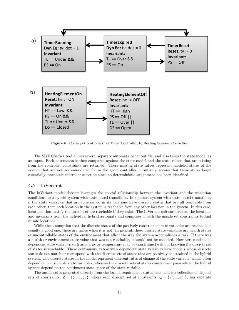
Figure 8: Coffee pot controllers: a) Timer Controller, b) Heating Element Controller.
The SBT Checker tool allows several separate automata per input file, and also takes the state model asan input. Each automaton is then compared against the state model and the state values that are missingfrom the controller constraints are returned. These missing state values represent modeled states of thesystem that are not accommodated for in the given controller; intuitively, means that these states begetessentially stochastic controller selection since no deterministic assignment has been identified.
4.5 InVeriant
The InVeriant model checker leverages the special relationship between the invariant and the transitionconditions for a hybrid system with state-based transitions. In a passive system with state-based transitions,if the state variables that are constrained in its locations have discrete states that are all reachable fromeach other, then each location in the system is reachable from any other location in the system. In this case,locations that satisfy the unsafe set are reachable if they exist. The InVeriant software creates the locationsand invariants from the individual hybrid automata and composes it with the unsafe set constraints to findunsafe locations.
While the assumption that the discrete states of the passively constrained state variables are reachable isusually a good one, there are times when it is not. In general, these passive state variables are health statesor uncontrollable states of the environment that affect the way the system accomplishes a task. If there wasa health or environment state value that was not reachable, it would not be modeled. However, continuousdependent state variables such as energy or temperature may be constrained without knowing if a discrete setof states is reachable. These continuous, rate-driven dependent state variables have models whose discretestates do not match or correspond with the discrete sets of states that are passively constrained in the hybridsystem. The discrete states in the model represent different rates of change of the state variable, which oftendepend on controllable state variables, whereas the discrete sets of states constrained passively in the hybridsystem depend on the continuous state space of the state variable.
The unsafe set is generated directly from the formal requirement statements, and is a collection of disjointsets of constraints, Z = {ζ1, ..., ζn}, where each disjoint set of constraints, ζi = {zi1, ..., z
ini
}, has separate
14

constraints on individual state variables, and each separate constraint z ∈ (Xd ∪ Xc ∪D ∪ Dc) ×Q × (R ∪Λ)
constrains a discrete controllable state variable (Xd), the rate of a continuous controllable state variable(Xc), a passive state variable, or the rate of a continuous, rate-driven dependent state variable. Q is theset of equality and inequality operators. The sets ζ of unsafe constraints are analogous to locations of thehybrid system, though the different sets in Z are not necessarily incompatible with one another; they aresimply separate unsafe conditions against which the designer wishes to verify the system.
The verification algorithm goes through the following steps to verify a system versus the unsafe set, Z.A representation of this algorithm is shown in Fig. 9.
1. Find all locations v ∈ V by composing the individual hybrid automata. Merge controlled constraintsin each location and record any inconsistent controlled constraints. If there are any, stop and reportwhich constraints are inconsistent. If not, continue.
2. For each di ∈ D, the set of discrete states constrained passively in the hybrid system is Λi. Let Mi bethe model of di, where µij ∈Mi is a discrete location in the model. For di ∈ D
d, Λi ≡Mi. However, fordi ∈ D
c, the discrete sets are not always equivalent. Set V ′ = V ; for each di ∈ Dc such that Λi ≠Mi,
V ′ = V ′ ○Mi = {vl ○ µj ∣∀vl ∈ V,∀µj ∈ Mi, vl, µj are consistent }. A composed location v′ = v ○ µis defined as having a combined invariant, inv(v′) = inv(v) ∧ inv(µ) and combined flow conditions,ψv′ = ψv ∧ ψµ.
3. For each ζ ∈ Z, find the composition of the hybrid system and the unsafe set, Yζ = V′ ○ ζ = {vj ○ ζ ∣∀vj ∈
V, vj and ζ are consistent }. Note that in this case, like the dependent case above, flow equations onthe same state variable are consistent not if they can be merged, but that they are equal. Label alllocations y ∈ Yζ as unsafe and output them.
4. Let the function cons() return the constrained value of a state variable when the function is giventhat state variable and a location (or set of constraints) as inputs. If there exists a di ∈ D
c suchthat cons(di, y) exists, then a path must be found from init(di) to cons(di, y). There exists someλij , λ
il ∈ Λi such that init(di) ∈ λij and cons(di, y) ∩ λ
il ≠ ∅, where Λi = {λi1, ..., λ
ij , ..., λ
il, ..., λ
ini
} is a
forward or backward ordered set. Let Λζi = {λij , ..., λil} be the set containing the two discrete sets
of passively constrained values that satisfy the initial and unsafe constraints and all discrete setsof states in between. Then for each λin ∈ Λζi , a location v ∈ V ′ must be found such that (λin ⊧
inv(v)) ∧ (sign(cons(di, v)) = sign(cons(di, y) − init(di))) is true. If such a path can be found, theunsafe set is reachable. This is not yet implemented in the current version of InVeriant.
This procedure is guaranteed by construction to find all locations in which unsafe conditions can occur.By leveraging the system’s structure, this method is more efficient than other symbolic model checkers suchas PHAVer and HyTech that deal with similar types of systems and it also allows some reasoning about theflow of continuous state variables. Currently, there is no automatic way to create unsafe set representationsas locations of an automaton needed for InVeriant, so manual incorporation is necessary. Due to the lackof ability to represent a disjunction between passive and controlled state variable constraints in the currentmodel framework, these are instead represented as separate unsafe locations with no loss of correctness.The formal requirement statements must also be negated for proper combination with the overall controllerautomaton. Automation of the proper incorporation of the unsafe set directly from the RCE output is afuture goal.
To complete the coffee pot example, the model and controller automata were run through InVeriantalong with the formal requirements in unsafe location form, and the model checker found that RequirementCP4 did not hold when the controller was in the combined locations “HeaterElementOff+TimerExpired”and “HeaterElementOff+TimerRunning.” This is because Requirement C4 does not take into account thetimer value, which also affects the powered state of the heating element as per CP2. Therefore, to have arequirement that dictates when the heating element is on, all such affecting state variables must be included.Updating CP4 to “The coffee pot shall turn on the heating element when the power switch is turned on, thetimer is running, and the temperature is lower than the maximum limit.” allowed the coffee pot controllersto satisfy all requirements.
15

Figure 9: Representation of the InVeriant verification algorithm.
5 Requirements Engineering and Early Design Process
During the development of the examples used to test the tool chain, a design process was developed andanalyzed with a eye towards the types of systems and requirements that would most benefit from the useof this tool. The design process, which results in three products (requirements, state model, and controllermodel), is outlined here.
Requirements engineering is the art of describing a specific need within an appropriate scope. Definingthe parameters of how the need must be addressed is the root of requirements. Requirements have differentlevels; the first level of requirements speak in general about the problem to be solved. As more levels ofrequirements are generated, the specifications become more detailed. Requirements at the subsystem levelshould fully constrain the design space in which the system is to be created; however, they should notoverconstrain it. This design process assumes a nominal requirements engineering process in which designersfollow basic best-practices when designing requirements. The requirements that work best with this tool arethose that constrain the control space of a software system. Since the process is state-based, requirementsthat indicate changes of state that affect the system are best suited for this tool chain. In general, functionalrequirements are the type that fits this definition.
The state model described in Section 3 derives from the requirements. State variables and their associatedvalues are found in the requirements; complete sets of requirements should cover all values that a statevariable can take in order to cover controller behavior in all modeled states. Controlled constraints andmerge conditions on those constraints should be derived from requirements, as well. If while generating themodel necessary for this tool chain, a designer uncovers questions unanswered by the requirements, then itis likely that the set of requirements is incomplete and that must be remedied.
The controller model is designed based on the state model and the requirements, using the SBT Checkertool. As design decisions are made that determine behavior (not just model abstraction decisions), thesemust cause updates of the requirements, the state model, or both. Controller design follows the definitionof linear hybrid automata given in Section 2.2. Both the state model and the controller model are specifiedin XML format; the requirements must have a label in square brackets proceeding each requirements, andare specified in a text file.
16

6 Examples
Two other examples were used to test and validate the VARED tool chain, and they are described in thissection.
6.1 Vending Machine
The Vending Machine example describes a simple machine that vends selected items when available andenough money has been collected. The requirements, model, and early controller design are outlined here,along with results of using the verification and analysis tool.
Table 5 lists the requirements for the vending machine example, along with their translations to SALT.A summary of the state model for the vending machine can be found in Table 6. As with the coffee potexample, the state variables that are affected by the human user are modeled as passive. The coin valuestate variable models which coins are inserted. It is path-dependent because it assumes a value of zero forany time periods during which a new coin is not entered. If another assumption made is that the rate of thecontroller is faster than it is possible for a human to enter consecutive coins, the coin value state variablewould need to visit the value of zero between each other value. The time period assumption is important tothe verification of the controller, in order to ensure that coins are not missed by the controller as they areinserted.
When the formalized requirements statements were run through the LCC, all came back as satisfiable.The vacuity check did find several expressions, however. These are listed in Table 7. No changes to therequirements were made based on this analysis.
The controller model was subsequently created, and it is made up of four separate automata, each ofwhich covers some subset of the requirements. Figures 10 and 11 illustrate these controller models. The CoinInsertion Controller depicted in Figure 10a dictates reactions to the coin value state variable and derivesfrom requirements VM1-VM3. In particular, the coin count is increased when a coin is deposited until itreaches or exceeds the default price. At that point, any coins deposited will be returned. The Display ChoiceController in Figure 10b determines what is displayed at the user prompt, and derives from requirementsVM4-VM6. The Coin Return Controller in Figure 11a determines the machine’s behavior when the coinreturn button is pressed and derives from requirement VM7. Finally, the Dispense Selection Controller inFigure 11b controls when an item is dispensed and derives from requirements VM8-VM9.
When the controller models were run through the SBT Checker design for verification tool, it wasfound that the Display Choice Controller was missing a control law for the state CA=AVAILABLE &IM=ENOUGH & SB=SELECTION. Since this state describes when the machine is vending, a new statewas added to the display choice controlled state variable (VENDING), and a new location was added to theDisplay Choice Controller, as shown in Figure 12.
Subsequently, the controllers were checked with the InVeriant model checker against the negation of therequirements (as the unsafe set). InVeriant failed to merge controlled constraints on the change state variablefor two locations, one in the Coin Insertion Controller (NotEnoughMoney) and the Coin Return Controller(CoinReturn). Both locations constrain the change state variable using a “reset” controlled constraint,and the modeled guard on allowing merges on two “reset” constraints require the constrained values to bethe same. In this case, the merger of these two locations would more aptly be modeled by summing theconstrained values of the two “reset” constraints; in order to make this change in the state model, however,the Dispense Selection Controller must be updated to guard against dispensing an item at the same time asthe coin return is pressed. Without this update, shown in Figure 13, the controller would reward a trickycustomer with a free item as it both dispensed the selection and returned its full cost.
With the merge conflict resolved, InVeriant was able to check the controller model against the unsafeset. The verification run found that two requirements could be violated by certain controller locations. Bothrequirements VM5 and VM8 would fail in locations where the appropriate invariant conditions were satisfiedand the selection was not available. For requirement VM5, the controller was written that it would defaultto the MAKEANOTHERSELECTION message if a selection was not available regardless of the amount ofmoney input. For requirement VM8, the selection would not dispense if it was unavailable. In both cases,simply adding the phrase “and the selection is available” to the requirement satisfied both the intent of therequirements and the verification of the controller model.
17

Table 5: Vending Machine Requirements
Requirement SALT TranslationVM1 The vending machine software assert always
shall add coin value to (“CV!=0” impliesthe coin count when a next “ccAdd=CV”)coin is inserted.
VM2 The vending machine software assert always (“dm=cc”)shall display current coin count.
VM3 The vending machine software assert always (“IM=ENOUGH”shall not accept coins if implies (“CV=0”enough money inserted. or “ch=CV”))
VM4 The vending machine software assert alwaysshall display a message (“SB=NOSELECTION” implies“Make a Selection” if there “dc=MAKESELECTION”)is no selection chosen.
VM5 The vending machine software assert always ((“SB=SELECTION”shall display a message “Insert & “IM=NOTENOUGH”)Money” if the selection is chosen, implies (“dc=INSERTMONEY”))but not enough money inserted.
VM6 The vending machine software assert always ((“SB=SELECTION”shall display a message “Make & “CA=UNAVAILABLE”)Another Selection” if the impliesselection is not available. (“dc=ANOTHERSELECTION”))
VM7 The vending machine software assert alwaysshall return the inserted (“CR=RETURN” impliesmoney if the coin return (“ch=cc” &button is pushed. “cc=0”))
VM8 The vending machine software assert always ((“IM=ENOUGH”shall dispense the selection, & “SB=SELECTION”) impliesif enough money inserted. (“ds=DISPENSING”))
VM9 The vending machine software assert alwaysshall calculate and dispense the (“ds=DISPENSING” implieschange, if selection dispensed. (“ccSub=100” & “cc=0”))
18

Table 6: Vending Machine State Model
Variable Name Abbrev. Type ValuesInserted Money IM Stochastic ENOUGH
NOTENOUGHCoin Return CR Stochastic COLLECT
RETURNSelection Button SB Stochastic NOSELECTION
SELECTIONChoice Available CA Stochastic AVAILABLE
UNAVAILABLECoin Value CV Path-Dependent 0, 5, 10, 25Coin Count cc Controlled [0,120] ∈ I
Change ch Controlled [0,145] ∈ IDispense Selection ds Controlled DISPENSING
NOTDISPENSINGDisplay Choice dc Controlled MAKESELECTION
INSERTMONEYANOTHERSELECTION
Display Money dm Controlled [0.0,1.20] ∈R
Table 7: Vending Machine Formal Requirements Vacuity Analysis
Requirement in PANDA Vacuous ExpressionsVM1 G((CV ≠ 0)→ (X(ccAdd = CV ))) CV ≠ 0VM2 G(dm = cc) TL = OV ERVM3 G((IM = ENOUGH)→ IM = ENOUGH
((CV = 0)∣(ch = CV )))
VM4 G((SB = NOSELECTION)→ SB = NOSELECTION(dc =MAKESELECTION))
VM5 G(((SB = SELECTION) SB = SELECTION&(IM = NOTENOUGH)) IM = NOTENOUGH→ (dc = INSERTMONEY ))
VM6 G(((SB = SELECTION) SB = SELECTION&(CA = UNAV AILABLE)) CA = UNAV AILABLE
→ (dc = ANOTHERSELECTION))
VM7 G((CR = RETURN)→ CR = RETURN((ch = cc)&(cc = 0)))
VM8 G(((IM = ENOUGH) IM = ENOUGH&(SB = SELECTION)) SB = SELECTION→ (ds =DISPENSING))
VM9 G((ds =DISPENSING)→ ds =DISPENSING((ccSub = 100)&(cc = 0)))
19

Figure 10: Vending Machine Controllers. a) Coin Insertion Controller, b) Display Choice Controller.
One final unsafe location was found, which also violated Requirement VM8. The controller location thatresults from the state when the vending machine was about to dispense a selection (that was available andfor which enough money had been entered), but the tricky customer hits the coin return button. In thiscase, the vending machine does not dispense the item, and rightfully so. The correct update for this failureis to append another phrase to this requirement stipulating the state of the coin return button.
6.2 Simplified Aid for Extravehicular Activity Rescue Example
The VARED tool was demonstrated on a real-world example, the International Space Station (ISS) SimplifiedAid for EVA Rescue (SAFER). The ISS SAFER, Figure 14, is a small, self-contained, 24-jet free-flyer thatprovides adequate propellant and control capability to allow an extravehicular activity (EVA) crew memberto maneuver near the ISS. The ISS SAFER is controlled in six degrees-of-freedom through crew personinputs from a single hand controller that is attached to the ISS SAFER. The avionics software consists offour subsystems: Activation, Motion Control, Command Interpreter, and Fault Detection and Checkout.These subsystems work together to take crew member inputs from the controller and to safely and reliablytranslate them into the appropriate thruster firings. The requirements for this software currently exist, anda subset of the software requirements were used. Requirements were mainly selected based on relevance toa type of controller, for example, the Automatic Attitude Hold (AAH) controller or controllers affected byHand Controller Module (HCM) inputs, for ease of modeling. The full list of requirements used is as follows:
IS121 The ISS SAFER avionics software shall initiate activation when the HCM Power/Test Switch is movedfrom the “OFF” position to the “ON” position.
IS133 The ISS SAFER avionics software shall initiate activation when the HCM Power/Test Switch is movedfrom the “OFF” position to the “TSTON” position.
IS065 The ISS SAFER avionics software shall initiate the AAH after seating the thrusters during activation.
IS012 The ISS SAFER avionics software shall ignore any hand controller rotation command present at the
20

Figure 11: Vending Machine Controllers. a) Coin Return Controller, b) Dispense Selection Controller.
Figure 12: Redesigned Display Choice Controller based on SBT Checker analysis.
21

Figure 13: Redesigned Dispense Selection Controller based on controlled constraint analysis.
time AAH is initiated until a return to the off condition is detected for that axis or until AAH isdisabled.
IS015 The ISS SAFER avionics software shall terminate the AAH for all three axes if valid rate sensor datais not received for more than one second.
IS067 The ISS SAFER avionics software shall determine whether the system is in the rotate or translatemode based on the control mode switch position
IS068 The ISS SAFER avionics software shall interpret the 4 axis inputs as X, pitch, yaw, and roll if thecontrol mode switch is in the rotate position.
IS069 The ISS SAFER avionics software shall interpret the 4 axis inputs as X, pitch, Y, and Z if the controlmode switch is in the translate position.
IS070 The ISS SAFER avionics software shall prioritize the pilot translational commands such that accel-eration is provided only along one translational axis with the priority being X first, Y second, and Zthird.
IS017 The ISS SAFER avionics software shall enable the AAH on all three rotational axes if an AAH buttonsingle click is indicated by the HCM.
IS076 The ISS SAFER avionics software shall perform the following actions when AAH is enabled:
(a) Enable AAH for all three axes.
(b) Set the displacement estimates of the three axes to zero.
(c) Set the AAH mode to deceleration.
(d) Light the HCM AAH light-emitting diode (LED).
IS016 The ISS SAFER avionics software shall disable the AAH on an axis if a crew member rotation commandis initiated for that axis.
IS018 The ISS SAFER avionics software shall disable the AAH on all three rotational axes if an AAH buttondouble click is indicated by the HCM .
IS077 The ISS SAFER avionics software shall perform the following actions when the AAH is disabled:
(a) Disable AAH for all three axes.
22

Figure 14: SAFER.
(b) Set the AAH mode to OFF.
(c) Turn OFF the HCM AAH LED.
IS019 The ISS SAFER avionics software shall terminate the AAH for all three axes if a Self-Test is initiated.
The ISS SAFER model is summarized in Table 8. The model is split between physical state variables(buttons on the Hand Controller Module, sensors, thruster) and software or virtual state variables. Thephysical state variables are modeled as passive state variables, and the software state variables are generallymodeled as controlled state variables. Two exceptions are the sw control activation and the sw self test statevariables. These are modeled as passive because the requirements that dictate when these state variableschange values were not included in this example. To do so would have added more complexity to an alreadylengthy example, but there are no technical reasons why these requirements could not also have been handled.
The corresponding SALT code is as follows:
IS121 assert always ((“hcm power=OFF” and next “hcm power=ON”) implies next“sw control activation=1”)
IS133 assert always ((“hcm power=OFF” and next“hcm power=TSTON”) implies next “sw control activation=1”)
IS065 assert always (“sw control activation=3” implies(“sw aah power pitch=ENABLED” and
23

Table 8: ISS SAFER State Model
Variable Name Type Valueshcm power Stochastic ON, OFF,
TSTONhcm control mode Stochastic TRANS, ROThcm aah button Path-Dependent STATIC
SINGLECLICKDOUBLECLICK
hcm aah led Controlled ON, OFFhcm input1 Path-Dependent ZERO, PLUS,
PLUSMINUS
hcm input2 Path-Dependent ZERO, PLUS,MINUS
hcm input3 Path-Dependent ZERO, PLUS,MINUS
hcm input4 Path-Dependent ZERO, PLUS,MINUS
thrusters Stochastic SEATEDNOTSEATED
rateSensor imuHealth Stochastic GOOD, FAILsw control mode Controlled TRANS, ROT
sw aah power pitch Controlled DISABLEDENABLED
sw aah power yaw Controlled DISABLEDENABLED
sw aah power roll Controlled DISABLEDENABLED
sw aah mode pitch Controlled OFF, DECELsw aah mode yaw Controlled OFF, DECELsw aah mode roll Controlled OFF, DECELsw control xdot Controlled HCM INPUT1
NOTASSIGNEDsw control ydot Controlled HCM INPUT3
NOTASSIGNEDsw control zdot Controlled HCM INPUT4
NOTASSIGNEDsw control yawdot Controlled HCM INPUT3
NOTASSIGNEDsw control pitchdot Controlled HCM INPUT2
NOTASSIGNEDsw control rolldot Controlled HCM INPUT4
NOTASSIGNEDsw control activation Path-Dependent OFF, 1, 2, 3sw control self test Stochastic IDLE, ACTIVE
24

“sw aah power yaw=ENABLED” and“sw aah power roll=ENABLED”))
IS015 assert always (“rateSensor imuHealth=FAIL” implies(“sw aah mode pitch=OFF” and “sw aah mode yaw=OFF”and “sw aah mode roll=OFF”))
IS067a assert always (“hcm control mode=TRANS” implies“sw control mode=TRANS”)
IS067b assert always (“hcm control mode=ROT” implies“sw control mode=ROT”)
IS068 assert always (“hcm control mode=ROT” implies(“sw control xdot=HCM INPUT 1” and“sw control pitchdot=HCM INPUT 2” and“sw control yawdot=HCM INPUT 3” and“sw control rolldot=HCM INPUT 4” and“sw control ydot=NOTASSIGNED” and“sw control zdot=NOTASSIGNED”))
IS069 assert always (“hcm control mode=TRANS” implies(“sw control xdot=HCM INPUT 1” and“sw control pitchdot=HCM INPUT 2” and“sw control ydot=HCM INPUT 3” and“sw control zdot=HCM INPUT 4” and“sw control yawdot=NOTASSIGNED” and“sw control rolldot=NOTASSIGNED”))
IS070a assert always ((“hcm control mode=TRANS” and(“hcm aah input1=PLUS” or “hcm aah input1=MINUS”))implies (“sw control xdot=HCM INPUT 1” and“sw control ydot=NOTASSIGNED” and“sw control zdot=NOTASSIGNED”))
IS070b assert always ((“hcm control mode=TRANS”and “hcm aah input1=ZERO” and (“hcm aah input3=PLUS” or“hcm aah input3=MINUS”)) implies(“sw control ydot=HCM INPUT 3” and“sw control zdot=NOTASSIGNED”))
IS070c assert always ((“hcm control mode=TRANS”and “hcm aah input1=ZERO” and “hcm aah input3=ZERO”and (“hcm aah input4=PLUS” or “hcm aah input4=MINUS”))implies “sw control zdot=HCM INPUT 4”)
IS017 assert always (“hcm aah button=SINGLECLICK” implies(“sw aah power pitch=ENABLED” and“sw aah power yaw=ENABLED” and“sw aah power roll=ENABLED”))
IS076 assert always (“hcm aah button=SINGLECLICK” implies(“sw aah power pitch=ENABLED” and“sw aah power yaw=ENABLED” and“sw aah power roll=ENABLED” and“sw aah mode pitch=DECEL” and“sw aah mode yaw=DECEL” and“sw aah mode roll=DECEL” and “hcm aah led=ON”))
25

IS016a assert always ((“hcm aah input2=PLUS” or“hcm aah input2=MINUS”) implies “sw aah mode pitch=OFF”)
IS016b assert always ((“hcm control mode=ROT” and(“hcm aah input3=PLUS” or “hcm aah input3=MINUS”))implies “sw aah mode yaw=OFF”)
IS016c assert always ((“hcm control mode=ROT” and(“hcm aah input4=PLUS” or “hcm aah input4=MINUS”))implies “sw aah mode roll=OFF”)
IS018 assert always (“hcm aah button=DOUBLECLICK” implies(“sw aah power pitch=DISABLED” and“sw aah power yaw=DISABLED” and“sw aah power roll=DISABLED”))
IS077 assert always (“hcm aah button=DOUBLECLICK” implies(“sw aah power pitch=DISABLED” and“sw aah power yaw=DISABLED” and“sw aah power roll=DISABLED” and “sw aah mode pitch=OFF” and“sw aah mode yaw=OFF” and “sw aah mode roll=OFF” and“hcm aah led=OFF”))
IS019 assert always (“sw control self test=ACTIVE” implies(“sw aah mode pitch=OFF” and “sw aah mode yaw=OFF” and“sw aah mode roll=OFF”))
IS012a assert always ((“sw aah mode pitch=DECEL” and“sw aah power pitch=ENABLED”) implies(“sw control pitchdot=NOTASSIGNED” until(“sw aah mode pitch=OFF” or“sw aah power pitch=DISABLED”)))
IS012b assert always ((“sw aah mode yaw=DECEL” and“sw aah power yaw=ENABLED”) implies(“sw control yawdot=NOTASSIGNED” until(“sw aah mode yaw=OFF” or “sw aah power yaw=DISABLED”)))
IS012c assert always ((“sw aah mode roll=DECEL” and“sw aah power roll=ENABLED”) implies(“sw control rolldot=NOTASSIGNED” until(“sw aah mode roll=OFF” or “sw aah power roll=DISABLED”)))
Multi-part requirements, or requirements affecting a set of state variables, are broken up into differentstatements with no loss of generality or expression.
These requirements were run through the LCC tool. All specifications were satisfiable given the model,which would be expected. Several vacuous expressions were found for the list of requirements. More workcould be explored with this rich example using combinations of requirements as well as feeding back vacuityinformation into the satisfiability checks. In particular, combinations of requirements IS012 and IS016 wouldbe interesting to analyze in this way.
Four basic controllers were designed from the requirements selected. The Power Controller, shown inFigure 15, resets state variables based on the power state of the ISS SAFER. The Mode Controller, shown inFigure 16a, assigns the software control mode and the software directional control inputs to hand controllerinputs based on the state of the hand controller’s mode switch. The AAH Controller, shown in Figure 16b,represents a separate controller for each of the three attitude axis (pitch, yaw, and roll), and commands theAAH power and mode per axis based on several inputs. Finally, the Command Inputs Controller, shown inFigure 17, assigns software directional control inputs to hand controller inputs based on both mode and the
26

Figure 15: ISS SAFER Power Controller.
Figure 16: ISS SAFER Controllers. a) Mode Controller and b) AAH Controller.
27

Figure 17: ISS SAFER Command Inputs Controller.
28

Figure 18: Redesigned ISS SAFER AAH Controller due to SBT Checker analysis.
order of operations in translational commands. For all controllers shown, the leading “sw ” was removedfrom appropriate state variables for readability.
The SBT Checker analysis found that each of the three AAH Controllers were missing controller locationsfor several states in the state space. A simple change to the invariant constraint on the hcm power statevariable from hcm power == OFF to hcm power ≠ ON in the Off location of each automata was sufficientto fix the problem. This now accounts for the hcm power state value of TSTON. The redesigned AAHControllers are shown in Figure 18.
When the controller model, the state model, and the requirements as the unsafe set were run throughInVeriant, several controlled constraint merge conflicts were uncovered. First, it was necessary to betterspecify the behavior of the hcm aah led when the AAH axes are in mixed power states. The requirementsare unclear on this; requirements IS076 and IS077 both mention the LED and both seem to pertain toactions when all axes are enabled or disabled. However, requirement IS016 clearly states that it is possibleto disable AAH per axis. Since the requirements are incomplete in this area, the choice was made to turnoff the hcm aah led whenever any AAH axis was disabled. The requirements should be updated to moreclearly specify this behavior. The second controlled constraint problem had to do with when the softwaredirectional control inputs were assigned to a hand controller input. If a location merge had constraints bothassigning and unassigning the inputs, the former constraint type was defined to reject that merge. A morecorrect behavior, based on the priorities given in requirement IS070, would be to prioritize unassignmentover assignment when merging dissimilar reset values. The model was updated to reflect that behavior.Finally, it was found that not only did the translational software directional inputs need this priority ofunassignment over assignment, but the rotational directional inputs did as well, due to requirement IS012.
Once the controlled constraint merge problems were addressed, InVeriant was able to find many reachableunsafe locations. Several requirements needed updates, such as requirements IS065, IS017 and IS076, whichneeded to include all of the conditions necessary to have the AAH enabled and in a mode. The AAHControllers had to be updated to allow the AAH to turn on when the hcm power was in the TSTONposition as well as the ON position, due to requirement IS133. This was incorrectly modified after the SBTChecker analysis, but caught by this tool. This update is shown in Figure 19.
Requirements IS068, IS069, and IS070 must specify that the hcm power state is not OFF to be entirelycorrect given the complete controller. Requirement IS069 also needs a concept of the priority betweentranslational axes found in Requirement IS070.
29

Figure 19: Redesigned ISS SAFER AAH Controller due to InVeriant verification.
7 Conclusions and Future Work
The VARED tool chain is meant to be a design process and a set of integrated tools that would bring formalmethods and analysis to the desktop of the requirements engineer. This effort was successful in many waysin achieving this, and has open work in other areas to more fully realize that vision. The VARED tool chainintegrates a state-based requirements and early design methodology for certain types of requirements withNLP and formal methods. The VARED tool has defined interfaces and a graphical user interface, shown inFigure 20, for using most of the parts of the tool chain.
The state-based design methodologies are sensical and expressive for functional software requirements.Performance-based requirements (such as “the controller shall have an overshoot less than” or “shall displaythe number to three decimal places...”) or requirements that spell out math algorithms (such as “thefilter shall be implemented using X algorithm...”), for example, are not well modeled by this methodology.Requirements that dictate control flow, like the many examples found in this report, do work well with thedesign methodology. Many times, it is this control flow that will suffer from incomplete requirements andmisunderstood behaviors more so than requirements that dictate performance requirements. Further workon the state-based design methodology would include creating more structure for choosing and modelingvariable types, particularly the dependent state variables.
The NLP integration in the VARED tool still needs a lot of work. The state model query functionalityis a good substitute for a domain-specific ontology. Sentence structures and language constructs commonlyfound in requirements are also well-handled by the new Edith extension. However, the NLP tool set remainsa tool for an expert user rather than a requirements engineer. More work is needed to bring this functionalityinto a domain common to the rest of the tools. First, many of the parts of STAT are unsupported open sourcetools that could be updated with supported open source libraries. Many of the communications betweenparts within STAT use sockets, which causes major problems when trying to port the heritage code to adifferent operating system, which is needed for closer integration with the rest of the VARED tool chain.Further efforts to make this tool more accessible to the requirement engineer’s desktop include creating moreuser prompts for using appropriate language and expanding the types of prepositional constructs and modelqueries that can be accommodated by the Edith tool.
The SBT Checker and InVeriant tools are very useful in pointing out problems with both the requirementsand the models. The LCC is not yet automated enough to be very useful, though most of the appropriate“checking” functionality is in place. An update from syntactic to trace vacuity detection is desired to handlemore complex formulas. Including automated requirement grouping and adjusting satisfiability checks basedon findings from the vacuity checks will allow more requirements problems to be caught in this stage insteadof later on during the controller model checking. This will aid designers when creating the controller models,
30

Figure 20: VARED Graphical User Interface.
as more decisions will be made explicit by the requirements.Further improvements to the InVeriant model checker would be to implement and increase the speed
of algorithms that must search along the paths of the appropriate state variables, given a set of initialconditions. It would also be beneficial to loosen the requirement that state-based transitions are basedon the passive state variables only, as less modeling abstraction would be needed in some cases. Finally,automatic insertion of requirements as the unsafe set would greatly speed up the verification process.
8 References
[1] V. Gervasi and D. Zowghi, “Reasoning about inconsistencies in natural language requirements,”ACM Trans. Softw. Eng. Methodol., vol. 14, pp. 277–330, July 2005. [Online]. Available:http://doi.acm.org/10.1145/1072997.1072999
[2] C. B. Achour, “Linguistic instruments for the integration of scenarios in requirement engineering,”in Proc. of the Third International Workshop on Requirements Engineering: Foundation for SoftwareQuality, 1997.
[3] M. Saeki, H. Horai, and H. Enomoto, “Software development process from natural languagespecification,” in Proc. of the 11th International Conference on Software Engineering. New York, NY,USA: ACM, 1989, pp. 64–73. [Online]. Available: http://doi.acm.org/10.1145/74587.74594
[4] P. P.-S. Chen, “English sentence structure and entity-relationship diagrams,” Information Sciences,vol. 29, no. 2-3, pp. 127 – 149, 1983. [Online]. Available: http://www.sciencedirect.com/science/article/pii/0020025583900142
31

[5] B.-S. Lee and B. R. Bryant, “Automated conversion from requirements documentation to an object-oriented formal specification language,” in Proc. of the 2002 ACM symposium on Applied computing.New York, NY, USA: ACM, 2002, pp. 932–936.
[6] G. Labinaz, M. M. Bayoumi, and K. Rudie, “A survey of modeling and control of hybrid systems,”Annual Reviews of Control, vol. 21, pp. 79–92, 1997.
[7] T. A. Henzinger, P.-H. Ho, and H. Wong-Toi, “HyTech: A model checker for hybrid systems,” Interna-tional Journal on Software Tools for Technology Transfer, 1997.
[8] K. Y. Rozier and M. Y. Vardi, “LTL satisfiability checking,” Int J Softw Tools Technol Transfer, 2010.
[9] P. Hansen and B. Jaumard, “Algorithms for the maximum satisfiability problem,” Computing, vol. 44,no. 4, pp. 279–303, 1990.
[10] M. X. Goemans and D. P. Williamson, “Improved approximation algorithms for maximum cut andsatisfiability problems using semidefinite programming,” Journal of the ACM (JACM), vol. 42, no. 6,pp. 1115–1145, 1995.
[11] J. P. Marques-Silva and K. A. Sakallah, “Grasp: A search algorithm for propositional satisfiability,”Computers, IEEE Transactions on, vol. 48, no. 5, pp. 506–521, 1999.
[12] M. Mezard, G. Parisi, and R. Zecchina, “Analytic and algorithmic solution of random satisfiabilityproblems,” Science, vol. 297, no. 5582, pp. 812–815, 2002.
[13] A. Gurfinkel and M. Chechik, “Robust vacuity for branching temporal logic,” ACM Transactions onComputational Logic (TOCL), vol. 13, no. 1, p. 1, 2012.
[14] I. Beer, S. Ben-David, C. Eisner, and Y. Rodeh, “Efficient detection of vacuity in temporal modelchecking,” Formal Methods in System Design, vol. 18, no. 2, pp. 141–163, 2001.
[15] R. Armoni, L. Fix, A. Flaisher, O. Grumberg, N. Piterman, A. Tiemeyer, and M. Y. Vardi, “Enhancedvacuity detection in linear temporal logic,” in Computer Aided Verification. Springer, 2003, pp. 368–380.
[16] E. M. Clarke and J. M. Wing, “Formal methods: State of the art and future directions,” ACM ComputingSurveys, vol. 28, no. 4, pp. 626–643, 1996.
[17] A. Cimatti, E. Clarke, E. Giunchiglia, F. Giunchiglia, M. Pistore, M. Roveri, R. Sebastiani, and A. Tac-chella, CAV. Springer-Verlag, 2002, vol. LNCS 2404, ch. NuSMV 2: An Open Source Tool for SymbolicModel Checking, pp. 359–364.
[18] J. Burch, E. Clarke, K. McMillan, D. Dill, and L. Hwang, “Symbolic model checking: 1020 statesand beyond,” in Proc. of the Fifth Annual IEEE Symposium on Logic in Computer Science, 1990, pp.428–439.
[19] F. Schneider, S. Easterbrook, J. Callahan, and G. Holzmann, “Validating requirements for fault tol-erant systems using model checking,” in Proc. of the Third International Conference on RequirementsEngineering, 1998, pp. 4–13.
[20] A. Biere, A. Cimatti, E. Clarke, and Y. Zhu, TACAS/ETAPS. Springer-Verlag, 1999, vol. LNCS 1579,ch. Symbolic Model Checking without BDDs, pp. 193–207.
[21] M. Franzle and C. Herde, “Hysat: An efficient proof engine for bounded model checking of hybridsystems,” Formal Methods in System Design, vol. 30, pp. 179–198, 2007, 10.1007/s10703-006-0031-0.[Online]. Available: http://dx.doi.org/10.1007/s10703-006-0031-0
[22] K. L. McMillan, CAV. Springer-Verlag, 2002, vol. LNCS 2404, ch. Applying SAT Methods in Un-bounded Symbolic Model Checking, pp. 250–264.
32

[23] R. Alur, T. Henzinger, and P.-H. Ho, “Automatic symbolic verification of embedded systems,” IEEETransactions on Software Engineering, vol. 22, no. 3, pp. 181–201, 1996.
[24] G. Frehse, “PHAVer: Algorithmic verification of hybrid systems past HyTech,” in Proc. of the Interna-tional Conference on Hybrid Systems: Computation and Control, 2005.
[25] C. Flanagan and P. Godefroid, “Dynamic partial-order reduction for model checking software,” SIG-PLAN Not., vol. 40, no. 1, pp. 110–121, 2005.
[26] R. Bordini, M. Fisher, W. Visser, and M. Wooldridge, “State-space reduction techniques in agent veri-fication,” in Proc. of the Third International Joint Conference on Autonomous Agents and MultiagentSystems, 2004, pp. 896–903.
[27] D. Dvorak, M. Indictor, M. Ingham, R. Rasmussen, and M. Stringfellow, “A unifying framework forsystems modeling, control systems design, and system operation,” in Proc. of the IEEE Conference onSystems, Man, and Cybernetics, October 2005.
[28] D. Dvorak, R. Rasmussen, and T. Starbird, “State knowledge representation in the Mission Data Sys-tem,” in Proc. of the IEEE Aerospace Conference, 2002.
[29] M. D. Ingham, R. D. Rasmussen, M. B. Bennett, and A. C. Moncada, “Generating requirements forcomplex embedded systems using State Analysis and the Mission Data System,” Acta Astronautica,vol. 58, no. 12, pp. 648–661, June 2006.
[30] J. T. Malin, C. Millward, F. Gomez, and D. R. Throop, “Semantic annotation of aerospace problemreports to support text mining,” IEEE Intelligent Systems, vol. 25, pp. 20–26, 2010.
[31] J. T. Malin and D. R. Throop, “Basic concepts and distinctions for an aerospace ontology of functions,entities and problems,” in Proc. of IEEE Aerospace Conference, March 2007.
[32] A. Bauer, M. Leucker, and J. Streit, SALT: Structured Assertion Language for Temporal Logic. SpringerBerlin / Heidelberg, 2006, vol. LNCS 4260, pp. 757–775.
[33] M. B. Dwyer, G. S. Avrunin, and J. C. Corbett, “Patterns in property specifications for finite-stateverification,” in Proc. of Int’l Conf. of Software Engineering, 1999, pp. 411–420.
[34] A. Bauer and M. Leucker, “The theory and practice of SALT,” in Proc. of 3rd NASA Formal MethodsSymposium, April 2011.
[35] G. Holzmann, The Spin Model Checker: Primer and Reference Manual. Addison-Wesley, 2004.
[36] K. Y. Rozier and M. Y. Vardi, “A multi-encoding approach for LTL symbolic satisfiability checking,”in FM 2011: Formal Methods. Springer, 2011, pp. 417–431.
[37] J. M. B. Braman, “Safety verification and failure analysis of goal-based hybrid control systems,” Ph.D.dissertation, California Institute of Technology, 2009.
33

9 Appendices
9.1 STAT Installation Guide
34

1. a. b.
2. a. b. c.
3.
4.
5.
6. a. b.
STAT Installation
RequirementsInstallationKnown Issues
RequirementsVMWare or VirtualBoxCentOS 6.5 i386 DVD1 iso file (find a mirror here: )http://isoredirect.centos.org/centos/6/isos/i386/Internet connection (for downloading packages)EdithBundle.tar.gz (obtain here: )http://tommy.jsc.nasa.gov/projects/reconciler/tarSteel Bank Common Lisp
Go here: http://sourceforge.net/projects/sbcl/files/sbcl/1.0.37Get the binary tarball: sbcl-1.0.37-x86-linux-binary.tar.bz2
InstallationInstall CentOS using the iso file with defaults
Create user named analystUse at least 2GB of RAM and 2 cores
On initial boot up, change settings (for convenience)Turn off screensaver: System > Preferences > Screensaver > uncheck "Activate ..."Turn off sleep: System > Preferences > Power Management > Display = NeverTurn off updates: System > Preferences > Software Updates > Check = Never
Switch to root user (for all remaining steps)
su -
Install software dependencies (may take a while depending on your connection)
yum -y updateyum -y install java java-devel mysql MySQL-python mysql-server httpd gd-devel gccemacs autofs yum-utils perl-XML-Parser perl-GD perl-CPAN perl-YAML expat-devel
Configure perl and libraries. Enter the command and at the cpan prompt, enter the following (enter after each line)cpan
o conf build_requires_install_policy yeso conf prerequisites_policy followo conf commitexit
Then back at the linux prompt, do:
cpan Digest::SHA Test::More YAML::XS JSON::XS JSON XML::SAX XML::Simple GD::TextExtUtils::MakeMaker GD::Graph CGI::Pretty Lingua::Treebank Data::DumperData::Dump Date::Calc Spreadsheet::ParseExcel Time::HiRes
Configure hostname (this must be done after cpan)Open the file /etc/sysconfig/networkChange the line to say: HOSTNAME=

6.
b.
c. 7.
8.
9.
10.
11.
12.
HOSTNAME=testbed1.jsc.nasa.gov
Save the file and rebootInstall Steel Bank Common Lisp. Note, you may get documentation errors, this is ok. Browse to the directory where the tarball islocated, then:
tar xjvf sbcl-1.0.37-x86-linux-binary.tar.bz2cd sbcl-1.0.37-x86-linuxsh install.sh
Extract the EdithBundle. Browse to the directory where the tarball is located, then:
mkdir /tmp/edithcp EdithBundle.tar.gz /tmp/edithcd /tmp/edithtar xvf EdithBundle.tar.gz
Unpack the main STAT Source directory
cd /usr/lib/perl5/5.10.0mkdir -p --mode 0775 STATcd STATtar xzf /tmp/edith/stat_source.tar.gzcd ..chown -R analyst:users STAT
Unpack the UCF Source directory
cd /usr/lib/perl5/5.10.0tar xzf /tmp/edith/stat_ucf.tar.gzrm -f MyConfig.pmchmod 0775 UCF_NLP-stanfordchown -R analyst:users UCF_NLP-stanfordcd UCF_NLP-stanfordrm -f data/asdf-registry/*asdmake
Unpack the public STAT Source directory
cd /var/www/htmltar --mode 775 -xzf /tmp/edith/stat_source_public.tar.gzchown -R analyst:users *
Configure mysql

12.
13.
14.
15. 16.
a.
b.
service mysqld startchkconfig --add mysqldchkconfig --level 2345 mysqld onmysql -u root < /usr/lib/perl5/5.10.0/STAT/distribution/bin/mysql_setup
Change analyst login shell to tcsh
usermod -s /bin/tcsh analyst
Create the .tcshrc file. If you're still logged in as root, type , then open a new file called and add the following:exit ~/.tcshrc
#/bin/tcshrcsetenv PATH ${HOME}/bin:$PATHsetenv PERL5LIB/usr/lib/perl5/5.10.0/STAT:/usr/lib/perl5/5.10.0/UCF_NLP-stanford/perlsetenv PERL_AUTOINSTALL '--defaultdeps'setenv SPELLCORRECTOR_DIR/usr/lib/perl5/5.10.0/UCF_NLP-stanford/perl/SpellCorrectorsetenv PENNSERVER_SOCKET /tmp/socket/lispsocketsetenv PARSER_GROUP users setenv PERL_READLINE_NOWARN 1mkdir -p /tmp/socketalias Stat 'cd /usr/lib/perl5/5.10.0/STAT'alias ucf 'cd /usr/lib/perl5/5.10.0/UCF_NLP-stanford'
Reboot the computerTest the Installation
Type at the prompt, then run:Stat
perl -w Spreadsht/loadOnly.pl
Output should show something like:
Finished spread loadonly X at ...
Open a second terminal and run:
ucfcd lisp./setupsystem.sh
Then in the first terminal, run:

16.
b.
perl -w Vared/Vared.pl SAFER_SRS --verbose
Output should look something like:
SALT code dumped to ...
If all that works then you're done!
Known IssuesThe Stanford Parser (located in ucf/java/stanford-parser) seems to hang sometimes. You can find its process id (so you can kill it) by doing
ps aux|grep java

9.2 VARED Installation Guide
39

1.
2. a.
1. 2.
3.
1.
2.
VARED InstallationThe following set of instructions will guide the user in installation of the VARED software package.
Install DependenciesGet The CodeBuild The Code
Install DependenciesApt-get will take care of most of them for you
sudo apt-get install cmake build-essential qt4-dev-tools libboost-devlibboost-regex-dev libboost-filesystem-dev libreadline-dev libxerces-c-devlibcppunit-dev lib32stdc++6 libgmp-dev openjdk-7-jdk flex bison -y
Set up environmentJava home needs to be set before the code will build. Add the following to your .bashrc or equivalent, with locations changedwhere appropriate, and re-source
export JAVA_HOME=/usr/lib/jvm/java-7-openjdk-amd64
Get The CodeCreate a base directory where you'd like the VARED code to live, then to that directorycdUse git to clone the repository (you'll need your username/password), be sure to change the url where appropriate
git clone https://bitbucket.org/insert_correct_url/vared.git
Or if you received a tarball file, extract it:
tar zxf vared.tgz
Build The CodeBuild
cd varedmake
Source the generated setup file. This will set up the remaining environment variables needed. You may want to add this to your .bashrcor equivalent
source vared.bash
Note: Two clean targets are available, clean and spotless. Clean will remove the build, bin, and lib directories. Spotless will eliminatethe dependencies which are built such as YamlCpp, Panda, Readline, and SMV and force them to rebuild.

9.3 VARED User’s Guide
41

VARED User's GuideThis document guides a user in the operation of the Verification and Analysis of Requirements and Early Designs (VARED) software suite.
AcronymsConstructs
DomainsConditions
FilesModel FilesLocations Files
ApplicationsRCEVacuity CheckerSBT CheckerInVeriant
Graphical User Interface (GUI)LayoutOperating the GUI
AcronymsThe following acronyms are used in this guide:
VARED = Verification and Analysis of Requirements and Early Designs
SALT = Smart Assertion Language for Temporal logic
PANDA = Portfolio Approach to Navigating the Design of Automata
RCE = Requirements Conversion Engine
SBT = State Based Transition
Constructs
DomainsA Domain is a construct used to separate models into logical sub models to better model large systems. The domain tag in the model files isrequired but is currently unused and reserved for future development.
ConditionsA Condition as referred to in this documentation is a construct used by the VARED software to describe logical equations in code. Becauselogical equations can be nested, they translate well to XML. Using the Condition types AND, OR, EQ, NEQ, LT, LTE, GT, GTE let us buildcomplex logical equations quite simply.
An example equation
(VarV = 0 | VarW = 1 | VarX != 2) & (VarY > 3 | VarZ <= 4)
and its XML counterpart

<condition type="and"> <condition type="or"> <condition domain="test" stateVar="VarV" type="EQ" value="0" /> <condition domain="test" stateVar="VarW" type="EQ" value="1" /> <condition domain="test" stateVar="VarX" type="NEQ" value="2" /> </condition> <condition type="or"> <condition domain="test" stateVar="VarY" type="GT" value="3" /> <condition domain="test" stateVar="VarZ" type="LTE" value="4" /> </condition></condition>
Files
Model FilesModel files in VARED are designed to model a state based system. XML is used to describe each state variable, its states, transitions, andconstraints. The following is a simple example of two state variables.
<?xml version="1.0" encoding="UTF-8"?><domainList> <domain name="vendingmachine"> <stateVar name="IM" valueType="discrete" controlType="stochastic"description="Inserted money"> <state name="ENOUGH"> <transition toState="NOTENOUGH"/> </state> <state name="NOTENOUGH"> <transition toState="ENOUGH"/> </state> </stateVar> <stateVar name="ch" valueType="integer" controlType="controlled"description="Change"> <constraint type="Reset"> <reset type="EQ" value="F1"/> <merge type="Reset" resultType="Reset"> <mergeCondition type="EQ"> <variable side="left" name="F1"/> <variable side="right" name="S1"/> </mergeCondition> <mergedConstraint name="F1"/> </merge> </constraint> </stateVar> </domain></domainList>
A few things to note (by line number above):
Line 1: The standard XML file header, which is required
Line 3: The domain tag describes a simple name for the domain the state variables reside in. Future development may allow for multiple
Sample Model File

domains to interact with each other
Line 4: A State Variable description. The attributes used are as follows:
name = The name this variable will be referred to throughout the codevalueType = The data type of the value of this variable. It can be any of: discrete, real, or integercontrolType = The type of variable. It can be any of: controlled, dependent, path_dependent, or stochasticinitialCondition = The initial state the variable takesdescription = Any text the user desires to describe the variable
Line 5: A State description. Only used in discrete state variables, and a single attribute name is a string which describes the state.
Line 6: A Transition description. Describes a transition from the state in line 5 to the toState state describe in this tag. Not required for stochasticvariables.
Line 13: A Constraint description. Describes various constraints on this variable. This helps when merging the variable with others. The typecan be any description the user desires.
Line 14: A Reset description. On a merge, describes the value the variable takes on when reset.
Line 15: A Merge description. Describes what happens when this variable is merged with another variable using this constraint and merge type. The resultType is the final output constraint's type.
Line 16: A Merge Condition description. The condition which describes whether the merge is valid. The type is a Condition Type (describedelsewhere). The variables for the merge condition are described inside this tag.
Line 17: A Merge Condition variable. The variables described are used to determine whether the merge is valid, and re-used in themergedConstraint and reset tags to help determine the finall output constraint.
Line 20: A Merged Constraint. This tag name determines which side of the mergeCondition tag ends up in the final output constraint if the mergesucceeds.
There is also a element, which describes the flow equation of the state variable. It resides in the constraint element and takes a dynEquation t and attribute tag, using the same construct as a Condition.ype value
Locations FilesLocations files in VARED are used to describe the various control states the entire system can be in at any given time. XML is used to describeeach location and its conditions and constraints. The following is a simple example of two Locations and an unsafe Location.

<?xml version="1.0" encoding="UTF-8"?><locationList> <location auto="CoinReturnControl" name="CoinReturn"> <condition domain="vendingMachine" stateVar="CR" type="EQ" value="RETURN"/> <constraint type="Reset" domain="vendingMachine" variable="ch"> <value name="F1" value="cc"/> </constraint> <constraint type="Reset" domain="vendingMachine" variable="cc"> <value name="F1" value="0"/> </constraint> <constraint type="Reset" domain="vendingMachine" variable="dm"> </constraint> </location> <location auto="DispenseSelectionControl" name="Dispensing"> <condition type="and"> <condition domain="vendingMachine" stateVar="IM" type="EQ"value="ENOUGH"/> <condition domain="vendingMachine" stateVar="SB" type="EQ"value="SELECTION"/> <condition domain="vendingMachine" stateVar="CA" type="EQ"value="AVAILABLE"/> </condition> <constraint type="Reset" domain="vendingMachine" variable="ds"> <value name="F1" value="DISPENSING"/> </constraint> <constraint type="Reset" domain="vendingMachine" variable="ch"> <value name="F1" value="100"/> </constraint> <constraint type="Reset" domain="vendingMachine" variable="cc"> <value name="F1" value="0"/> </constraint> </location> <location auto="unsafe" name="Requirement4a"> <condition domain="vendingMachine" stateVar="SB" type="EQ"value="NOSELECTION"/> <constraint type="Reset" domain="vendingMachine" variable="dc"> <value name="F1" value="VENDING"/> </constraint> </location></locationList>
A few things to note (by line number above):
Line 1: The standard XML file header, which is required
Line 2: The full Location list. All locations go in this list.
Line 3: A Location description. The auto attribute specifies which automata this location is associated with, the name attribute is how theLocation will be described in the code and output.
Line 4: A Condition description. The Condition construct as described above is put into XML here. The domain and stateVar attributes refer backto the state variable involved in that condition. The type and value are as referred to in the Condition construct above.
Line 5: A Constraint description. The constraint tag has attributes for domain and variable, as referred to in the state variable which isconstrained. The value tag on line 6 is optional, and name/value are also as referred to in the state variable.
Line 30: This Location describes an unsafe location as referred to above. It's marked by a special automata name "unsafe".
Sample Locations File

1. 2. 3. 4. 5.
ApplicationsThere are four main applications available in the VARED software suite: RCE, Vacuity Checker, SBT Checker, and InVeriant. In order to run anyof the applications via the terminal, you must first source the vared.bash setup file:
It's encouraged to add this command to your .bashrc or equivalent.
source vared.bash
RCERCE accepts a Model file and a SALT file as input, and outputs a PANDA file. It may be run from the terminal with the following syntax:
bin/rce <model file> <salt file> <output file>
Vacuity CheckerVacuity Checker accepts a PANDA file as input. It may be run from the terminal with the following syntax:
bin/vaccheck <PANDA file>
SBT CheckerSBT Checker accepts a Model file and a Locations file. It may be run from the terminal with the following syntax:
bin/sbtcheck <model file> <location file>
InVeriantInVeriant accepts a Model file and a Locations file. It may be run from the terminal with the following syntax:
bin/inv <model file> <location file>
Graphical User Interface (GUI)
LayoutThe GUI for VARED has a few parts:
The Application selection combo boxFile selection paneRun button Some applications will have a Debug checkbox along with the Run buttonNote:Status output displayMain output display

1.
2.
3.
4.
5. 6.
7. 8.
Operating the GUIThe applications available in the VARED suite are all available as terminal applications, however the GUI makes them much simpler to run. Torun an application, follow these steps:
Ensure you have sourced the setup file in the terminal window you're running. It's encouraged to add this command tovared.bashyour .bashrc or equivalent.
source vared.bash
Start the GUI by running the binary file located in the directory of the VARED project.VaredGui bin
./bin/VaredGui
Select the application you'd like to run from the Application selection combo box. This will change the file selection pane to theappropriate input file types required by the selected application.Click the browse button(s) next to each input file and use the file browser to choose the appropriate file. : An output file will beNoteoverwritten if you choose an existing file.If the application you're running has a Debug checkbox, you may click it to get the debug information output from that application.Click the Run button. Your mouse pointer should change to a busy state during the run, and any status and/or errors will be displayed tothe Status output display.Depending on the application, the output will be displayed either continuously during the run, or all at the end, in the Main output display.To close the GUI, simply click the X in the title bar or use at the terminal window where the GUI was initially run.ctrl-C
A sample InVeriant run:


REPORT DOCUMENTATION PAGE Form Approved OMB No. 0704-0188
Public reporting burden for this collection of information is estimated to average 1 hour per response, including the time for reviewing instructions, searching existing data sources, gathering and
maintaining the data needed, and completing and reviewing the collection of information. Send comments regarding this burden estimate or any other aspect of this collection of information, including
suggestions for reducing this burden, to Washington Headquarters Services, Directorate for Information Operations and Reports, 1215 Jefferson Davis Highway, Suite 1204, Arlington, VA 22202-4302,
and to the Office of Management and Budget, Paperwork Reduction Project (0704-0188), Washington, DC 20503.
1. AGENCY USE ONLY (Leave Blank) 2. REPORT DATE 3. REPORT TYPE AND DATES COVERED
June 2015 Technical Publication
4. TITLE AND SUBTITLE
5. FUNDING NUMBERS
Formal Software Verification for Early Stage Design - Final Report
6. AUTHOR(S) Julia Badger
7. PERFORMING ORGANIZATION NAME(S) AND ADDRESS(ES) 8. PERFORMING ORGANIZATION REPORT NUMBERS
Lyndon B. Johnson Space Center
Houston, Texas 77058
S-1192
9. SPONSORING/MONITORING AGENCY NAME(S) AND ADDRESS(ES) 10. SPONSORING/MONITORING
AGENCY REPORT NUMBER
National Aeronautics and Space Administration
Washington, DC 20546-0001
TP-2015-218577
11. SUPPLEMENTARY NOTES
12a. DISTRIBUTION/AVAILABILITY STATEMENT 12b. DISTRIBUTION CODE
Unclassified/Unlimited Available from the NASA Center for AeroSpace Information (CASI) 7115 Standard Hanover, MD 21076-1320 Category: 18
13. ABSTRACT (Maximum 200 words)
The Verification and Analysis for Requirements and Early Design (VARED) tool chain has been developed to put tools for formal
methods analysis and model-based engineering methodologies on the desk of the software requirements engineer. The tool chain
consists of a natural language processing tool that, once given a set of requirements and a preliminary state model of the system under
design, can formalize the requirements in Linear Temporal Logic specifications. These formalized requirements can be checked for
consistency (satisfiability and vacuity). The designer is given tools for designing an early representation of the control system
described by the requirements, and the final part of the tool chain is a symbolic model checker that can be used to verify the controller
design against the formal requirements statements. This report describes the development of the tool chain and the state-based design
methodology used in the system development. Several example systems are presented and run through the tool chain, including a real
flight system, the International Space Station (ISS) SAFER (Simplified Aid for EVA Rescue). Finally, an analysis of the applicability
and strengths and weaknesses of the VARED tool chain is presented.
14. SUBJECT TERMS 15. NUMBER OF
PAGES
16. PRICE CODE
software engineering; verification; design; natural language processing; algorithms;
requirements; VARED; methods analysis; model-based engineering 60
17. SECURITY CLASSIFICATION
OF REPORT
18. SECURITY CLASSIFICATION
OF THIS PAGE
19. SECURITY CLASSIFICATION
OF ABSTRACT
20. LIMITATION OF ABSTRACT
Unclassified Unclassified Unclassified Unlimited
Standard Form 298 (Rev Feb 89) (MS Word Mar 97) Prescribed by ANSI Std. 239-18 298-102
NSN 7540-01-280-5500