Forced draught gas burners -...
40
20050458 (4) - 03/2014 Installation, use and maintenance instructions Forced draught gas burners Progressive two stage or modulating operation Code Model 20051492 RS 160/E 20050056 RS 160/E GB
Transcript of Forced draught gas burners -...

Installation, use and maintenance instructions
Forced draught gas burners
Progressive two stage or modulating operation
Code Model
20051492 RS 160/E
20050056 RS 160/E
GB
20050458 (4) - 03/2014


Contents
1 Information and general instructions . . . . . . . . . . . . . . . . . . . . . . . . . . . . . . . . . . . . . . . . . . . . . . . . . . . . . . . . . . . . . . . . . . . . . 3
1.1 Information about the instruction manual . . . . . . . . . . . . . . . . . . . . . . . . . . . . . . . . . . . . . . . . . . . . . . . . . . . . . . . . . . . . 31.1.1 Introduction . . . . . . . . . . . . . . . . . . . . . . . . . . . . . . . . . . . . . . . . . . . . . . . . . . . . . . . . . . . . . . . . . . . . . . . . . . . . . . . . . . 31.1.2 General dangers . . . . . . . . . . . . . . . . . . . . . . . . . . . . . . . . . . . . . . . . . . . . . . . . . . . . . . . . . . . . . . . . . . . . . . . . . . . . . . 31.1.3 Safety precautions . . . . . . . . . . . . . . . . . . . . . . . . . . . . . . . . . . . . . . . . . . . . . . . . . . . . . . . . . . . . . . . . . . . . . . . . . . . . . 31.1.4 Danger: live components . . . . . . . . . . . . . . . . . . . . . . . . . . . . . . . . . . . . . . . . . . . . . . . . . . . . . . . . . . . . . . . . . . . . . . . . 3
1.2 Guarantee and responsibility . . . . . . . . . . . . . . . . . . . . . . . . . . . . . . . . . . . . . . . . . . . . . . . . . . . . . . . . . . . . . . . . . . . . . 41.2.1 Owner’s responsibility . . . . . . . . . . . . . . . . . . . . . . . . . . . . . . . . . . . . . . . . . . . . . . . . . . . . . . . . . . . . . . . . . . . . . . . . . . 4
2 Safety and prevention. . . . . . . . . . . . . . . . . . . . . . . . . . . . . . . . . . . . . . . . . . . . . . . . . . . . . . . . . . . . . . . . . . . . . . . . . . . . . . . . . . 5
2.1 Introduction . . . . . . . . . . . . . . . . . . . . . . . . . . . . . . . . . . . . . . . . . . . . . . . . . . . . . . . . . . . . . . . . . . . . . . . . . . . . . . . . . . 52.2 Personnel training . . . . . . . . . . . . . . . . . . . . . . . . . . . . . . . . . . . . . . . . . . . . . . . . . . . . . . . . . . . . . . . . . . . . . . . . . . . . . 5
3 Technical description of the burner . . . . . . . . . . . . . . . . . . . . . . . . . . . . . . . . . . . . . . . . . . . . . . . . . . . . . . . . . . . . . . . . . . . . . . 6
3.1 Technical data . . . . . . . . . . . . . . . . . . . . . . . . . . . . . . . . . . . . . . . . . . . . . . . . . . . . . . . . . . . . . . . . . . . . . . . . . . . . . . . . 6
3.2 Electrical data. . . . . . . . . . . . . . . . . . . . . . . . . . . . . . . . . . . . . . . . . . . . . . . . . . . . . . . . . . . . . . . . . . . . . . . . . . . . . . . . . 6
3.3 Burner models designation . . . . . . . . . . . . . . . . . . . . . . . . . . . . . . . . . . . . . . . . . . . . . . . . . . . . . . . . . . . . . . . . . . . . . . 73.4 Packaging - weight - Approximate measurements. . . . . . . . . . . . . . . . . . . . . . . . . . . . . . . . . . . . . . . . . . . . . . . . . . . . . 7
3.5 Burner dimensions . . . . . . . . . . . . . . . . . . . . . . . . . . . . . . . . . . . . . . . . . . . . . . . . . . . . . . . . . . . . . . . . . . . . . . . . . . . . . 7
3.6 Burner equipment. . . . . . . . . . . . . . . . . . . . . . . . . . . . . . . . . . . . . . . . . . . . . . . . . . . . . . . . . . . . . . . . . . . . . . . . . . . . . . 73.7 Burner description . . . . . . . . . . . . . . . . . . . . . . . . . . . . . . . . . . . . . . . . . . . . . . . . . . . . . . . . . . . . . . . . . . . . . . . . . . . . . 8
3.8 Firing rate . . . . . . . . . . . . . . . . . . . . . . . . . . . . . . . . . . . . . . . . . . . . . . . . . . . . . . . . . . . . . . . . . . . . . . . . . . . . . . . . . . . . 93.8.1 Procedure to refer burner operating condition in high altitude plants. . . . . . . . . . . . . . . . . . . . . . . . . . . . . . . . . . . . . . . 9
3.9 Minimum furnace dimensions . . . . . . . . . . . . . . . . . . . . . . . . . . . . . . . . . . . . . . . . . . . . . . . . . . . . . . . . . . . . . . . . . . . 11
3.10 Commercial boilers . . . . . . . . . . . . . . . . . . . . . . . . . . . . . . . . . . . . . . . . . . . . . . . . . . . . . . . . . . . . . . . . . . . . . . . . . . . 11
3.11 Control box for the air/fuel ratio (LMV37.4...) . . . . . . . . . . . . . . . . . . . . . . . . . . . . . . . . . . . . . . . . . . . . . . . . . . . . . . . . 123.12 Actuators (SQM33.5...) . . . . . . . . . . . . . . . . . . . . . . . . . . . . . . . . . . . . . . . . . . . . . . . . . . . . . . . . . . . . . . . . . . . . . . . . 15
4 Installation . . . . . . . . . . . . . . . . . . . . . . . . . . . . . . . . . . . . . . . . . . . . . . . . . . . . . . . . . . . . . . . . . . . . . . . . . . . . . . . . . . . . . . . . . . 16
4.1 Notes on safety for the installation . . . . . . . . . . . . . . . . . . . . . . . . . . . . . . . . . . . . . . . . . . . . . . . . . . . . . . . . . . . . . . . . 16
4.2 Handling . . . . . . . . . . . . . . . . . . . . . . . . . . . . . . . . . . . . . . . . . . . . . . . . . . . . . . . . . . . . . . . . . . . . . . . . . . . . . . . . . . . . 16
4.3 Preliminary checks . . . . . . . . . . . . . . . . . . . . . . . . . . . . . . . . . . . . . . . . . . . . . . . . . . . . . . . . . . . . . . . . . . . . . . . . . . . . 164.4 Operation position . . . . . . . . . . . . . . . . . . . . . . . . . . . . . . . . . . . . . . . . . . . . . . . . . . . . . . . . . . . . . . . . . . . . . . . . . . . . 16
4.5 Boiler plate . . . . . . . . . . . . . . . . . . . . . . . . . . . . . . . . . . . . . . . . . . . . . . . . . . . . . . . . . . . . . . . . . . . . . . . . . . . . . . . . . . 17
4.6 Securing the burner to the boiler . . . . . . . . . . . . . . . . . . . . . . . . . . . . . . . . . . . . . . . . . . . . . . . . . . . . . . . . . . . . . . . . . 174.7 Electrode positioning . . . . . . . . . . . . . . . . . . . . . . . . . . . . . . . . . . . . . . . . . . . . . . . . . . . . . . . . . . . . . . . . . . . . . . . . . . 18
4.8 Combustion head adjustment . . . . . . . . . . . . . . . . . . . . . . . . . . . . . . . . . . . . . . . . . . . . . . . . . . . . . . . . . . . . . . . . . . . 18
4.9 Gas supply . . . . . . . . . . . . . . . . . . . . . . . . . . . . . . . . . . . . . . . . . . . . . . . . . . . . . . . . . . . . . . . . . . . . . . . . . . . . . . . . . . 204.9.1 Gas train. . . . . . . . . . . . . . . . . . . . . . . . . . . . . . . . . . . . . . . . . . . . . . . . . . . . . . . . . . . . . . . . . . . . . . . . . . . . . . . . . . . . 204.9.2 Gas feeding line . . . . . . . . . . . . . . . . . . . . . . . . . . . . . . . . . . . . . . . . . . . . . . . . . . . . . . . . . . . . . . . . . . . . . . . . . . . . . . 20
4.10 Gas pressure . . . . . . . . . . . . . . . . . . . . . . . . . . . . . . . . . . . . . . . . . . . . . . . . . . . . . . . . . . . . . . . . . . . . . . . . . . . . . . . . 21
4.11 Electrical wiring . . . . . . . . . . . . . . . . . . . . . . . . . . . . . . . . . . . . . . . . . . . . . . . . . . . . . . . . . . . . . . . . . . . . . . . . . . . . . . 224.12 Thermal relay calibration . . . . . . . . . . . . . . . . . . . . . . . . . . . . . . . . . . . . . . . . . . . . . . . . . . . . . . . . . . . . . . . . . . . . . . . 23
4.12.1 Electro-mechanical thermal relay. . . . . . . . . . . . . . . . . . . . . . . . . . . . . . . . . . . . . . . . . . . . . . . . . . . . . . . . . . . . . . . . . 234.12.2 Electronic thermal relay . . . . . . . . . . . . . . . . . . . . . . . . . . . . . . . . . . . . . . . . . . . . . . . . . . . . . . . . . . . . . . . . . . . . . . . . 23
4.13 Motor connection at 208-230 or 460V . . . . . . . . . . . . . . . . . . . . . . . . . . . . . . . . . . . . . . . . . . . . . . . . . . . . . . . . . . . . . 244.14 Motor connection at 575V . . . . . . . . . . . . . . . . . . . . . . . . . . . . . . . . . . . . . . . . . . . . . . . . . . . . . . . . . . . . . . . . . . . . . . 24
4.15 Reversible direction . . . . . . . . . . . . . . . . . . . . . . . . . . . . . . . . . . . . . . . . . . . . . . . . . . . . . . . . . . . . . . . . . . . . . . . . . . . 24
5 Start-up, calibration and operation of the burner . . . . . . . . . . . . . . . . . . . . . . . . . . . . . . . . . . . . . . . . . . . . . . . . . . . . . . . . . . 25
5.1 Notes on safety for the first start-up. . . . . . . . . . . . . . . . . . . . . . . . . . . . . . . . . . . . . . . . . . . . . . . . . . . . . . . . . . . . . . . 25
5.2 Adjustments before first firing. . . . . . . . . . . . . . . . . . . . . . . . . . . . . . . . . . . . . . . . . . . . . . . . . . . . . . . . . . . . . . . . . . . . 255.3 Burner start-up . . . . . . . . . . . . . . . . . . . . . . . . . . . . . . . . . . . . . . . . . . . . . . . . . . . . . . . . . . . . . . . . . . . . . . . . . . . . . . . 25
5.4 Combustion air adjustment . . . . . . . . . . . . . . . . . . . . . . . . . . . . . . . . . . . . . . . . . . . . . . . . . . . . . . . . . . . . . . . . . . . . . 265.4.1 Adjusting gas/air delivery . . . . . . . . . . . . . . . . . . . . . . . . . . . . . . . . . . . . . . . . . . . . . . . . . . . . . . . . . . . . . . . . . . . . . . . 265.4.2 Air/fuel control and power modulation system . . . . . . . . . . . . . . . . . . . . . . . . . . . . . . . . . . . . . . . . . . . . . . . . . . . . . . . 26
1 20050458GB

Contents
5.5 Final calibration of the pressure switches . . . . . . . . . . . . . . . . . . . . . . . . . . . . . . . . . . . . . . . . . . . . . . . . . . . . . . . . . . 265.5.1 Air pressure switch . . . . . . . . . . . . . . . . . . . . . . . . . . . . . . . . . . . . . . . . . . . . . . . . . . . . . . . . . . . . . . . . . . . . . . . . . . . 265.5.2 Maximum gas pressure switch . . . . . . . . . . . . . . . . . . . . . . . . . . . . . . . . . . . . . . . . . . . . . . . . . . . . . . . . . . . . . . . . . . 275.5.3 Minimum gas pressure switch . . . . . . . . . . . . . . . . . . . . . . . . . . . . . . . . . . . . . . . . . . . . . . . . . . . . . . . . . . . . . . . . . . . 27
5.6 Flame signal measurement . . . . . . . . . . . . . . . . . . . . . . . . . . . . . . . . . . . . . . . . . . . . . . . . . . . . . . . . . . . . . . . . . . . . . 27
5.7 Final checks (with the burner working) . . . . . . . . . . . . . . . . . . . . . . . . . . . . . . . . . . . . . . . . . . . . . . . . . . . . . . . . . . . . 27
6 Maintenance . . . . . . . . . . . . . . . . . . . . . . . . . . . . . . . . . . . . . . . . . . . . . . . . . . . . . . . . . . . . . . . . . . . . . . . . . . . . . . . . . . . . . . . . 28
6.1 Notes on safety for the maintenance . . . . . . . . . . . . . . . . . . . . . . . . . . . . . . . . . . . . . . . . . . . . . . . . . . . . . . . . . . . . . . 28
6.2 Maintenance programme. . . . . . . . . . . . . . . . . . . . . . . . . . . . . . . . . . . . . . . . . . . . . . . . . . . . . . . . . . . . . . . . . . . . . . . 286.2.1 Maintenance frequency . . . . . . . . . . . . . . . . . . . . . . . . . . . . . . . . . . . . . . . . . . . . . . . . . . . . . . . . . . . . . . . . . . . . . . . . 286.2.2 Checking and cleaning . . . . . . . . . . . . . . . . . . . . . . . . . . . . . . . . . . . . . . . . . . . . . . . . . . . . . . . . . . . . . . . . . . . . . . . . 28
6.3 Opening the burner . . . . . . . . . . . . . . . . . . . . . . . . . . . . . . . . . . . . . . . . . . . . . . . . . . . . . . . . . . . . . . . . . . . . . . . . . . . 29
6.4 Closing the burner . . . . . . . . . . . . . . . . . . . . . . . . . . . . . . . . . . . . . . . . . . . . . . . . . . . . . . . . . . . . . . . . . . . . . . . . . . . . 29
A Appendix - Spare parts . . . . . . . . . . . . . . . . . . . . . . . . . . . . . . . . . . . . . . . . . . . . . . . . . . . . . . . . . . . . . . . . . . . . . . . . . . . . . . . 30
B Appendix - Accessories . . . . . . . . . . . . . . . . . . . . . . . . . . . . . . . . . . . . . . . . . . . . . . . . . . . . . . . . . . . . . . . . . . . . . . . . . . . . . . . 33
C Appendix - Burner start up report. . . . . . . . . . . . . . . . . . . . . . . . . . . . . . . . . . . . . . . . . . . . . . . . . . . . . . . . . . . . . . . . . . . . . . . 34
20050458 2 GB

Information and general instructions
1.1 Information about the instruction manual
1.1.1 Introduction
The instruction manual supplied with the burner: is an integral and essential part of the product and must not be
separated from it; it must therefore be kept carefully for anynecessary consultation and must accompany the burner evenif it is transferred to another owner or user, or to another sys-tem. If the manual is lost or damaged, another copy must berequested from the Technical Assistance Service of the area;
is designed for use by qualified personnel; offers important indications and instructions relating to the
installation safety, start-up, use and maintenance of theburner.
Symbols used in the manual
In some parts of the manual you will see triangular DANGERsigns. Pay great attention to these, as they indicate a situationof potential danger.
1.1.2 General dangers
The dangers can be of 3 levels, as indicated below.
1.1.3 Safety precautions
Good safety practices must be used when working on burnerequipment. The potential energy in the electrical supply, fuel andrelated equipment must be handled with extreme care to preventequipment failures, injuries and potential death.
1.1.4 Danger: live components
Other symbols
This symbol indicates a list.
Abbreviations usedCh. ChapterFig. FigurePag. PageSec. SectionTab. Table
Delivery of the system and the instruction manual
When the system is delivered, it is important that: The instruction manual is supplied to the user by the system
manufacturer, with the recommendation to keep it in the roomwhere the heat generator is to be installed.
The instruction manual shows:– the serial number of the burner;
– the address and telephone number of the nearest Assis-tance Centre;
The system supplier carefully informs the user about:– the use of the system, – any further tests that may be necessary before the system is
started up, – maintenance and the need to have the system checked at
least once a year by the manufacturer or another specialisedtechnician.To ensure a periodic check, the manufacturer recommendsthe drawing up of a Maintenance Contract.
1 Information and general instructions
DANGER
Maximum danger level! This symbol indicates operations which, if not car-ried out correctly, cause serious injury, death orlong-term health risks.
WARNING
This symbol indicates operations which, if not car-ried out correctly, may cause serious injury, deathor long-term health risks.
CAUTION
This symbol indicates operations which, if not car-ried out correctly, may cause damage to the ma-chine and/or injury to people.
WARNING
If you smell gas, open window, extinguish any openflames, stay away from electrical switches, evacu-ate the building and immediately call the gas com-pany.
If this equipment is not installed, operated, operatedand maintained in accordance with the manufactur-ers intructions, this product could expose you tosubstances in fuel or from fuel combustion whichcan cause death or serious illness.
Improper servicing of this equipment may create apotential hazard to equipment and operators.
Servicing must be done by a fully trained andqualified personnel.
DANGER
This symbol indicates operations which, if not car-ried out correctly, lead to electric shocks with lethalconsequences.
ENVIRONMENTAL PROTECTION
This symbol gives indications for the use of the ma-chine with respect for the environment.
............................................................................................
...........................................................................................
...........................................................................................
...........................................................................................
3 20050458GB

Information and general instructions
1.2 Guarantee and responsibility
The manufacturer guarantees its new products from the installa-tion date, in accordance with the regulations in force and/or thesales contract. At the moment of the first start-up, check that theburner is integral and complete.
In particular, the rights to the guarantee and the responsibilitywill no longer be valid, in the event of damage to things or injuryto people, if such damage/injury was due to any of the followingcauses: incorrect installation, start-up, use and maintenance of the
burner; improper, incorrect or unreasonable use of the burner; intervention of unqualified personnel; carrying out of non authorised modifications on the equipment; use of the burner with safety devices that are faulty, incorrectly
applied and/or not working; installation of untested supplementary components on the
burner; powering of the burner with unsuitable fuels; faults in the fuel power supply system; use of the burner even following an error and/or an irregularity; repairs and/or overhauls incorrectly carried out; modification of the combustion chamber with inserts that pre-
vent the regular development of the flame, as structurallyestablished;
insufficient and inappropriate surveillance and care of thoseburner components most subject to wear and tear;
use of non-original components, including spare parts, kits,accessories and optionals;
force majeure.
the manufacturer furthermore declines any and every re-sponsibility for the failure to observe the contents of thismanual.
1.2.1 Owner’s responsibility
Please pay attention to the Safety Warnings contained withinthis instruction manual. Keep this manual for your records andprovide it to your quali fi ed service agency for use in profession-ally setting up and maintaining your burner.
Your burner will provide years of ef fi cient operation if it is pro-fessionally installed and maintained by a qualifi ed service tech-nician. If at any time the burner does not appear to be operatingproperly, immediately contact your qualifi ed service agency forconsultation.
We recommend annual inspection/service of your gas heatingsystem by a qualifi ed service agency.
Failure to follow these instructions, misuse, or incorrect adjust-ment of the burner could lead to equipment malfunction and re-sult in asphyxiation, explosion or fire.
WARNING
Failure to observe the information given in this man-ual, operating negligence, incorrect installation andthe carrying out of non authorised modifications willresult in the annulment by the manufacturer of theguarantee that it supplies with the burner.
WARNING
If you smell gas: Do not touch any electrical items. Open all windows. Close all gas supply valves. Contact your local gas authority immediately.
• Do not store flammable or hazardous materialsin the vicinity of fuel burning appliances.
• Improper installation, adjustment, alteration,service or maintenance can cause propertydamage, personal injury or death.
• Refer to this manual for instructional or addition-al information.
• Consult a certified installer, service representa-tive or the gas supplier for further assistance.
• Burner shall be installed in accordance withmanufacturers requirements as outlined in thismanual, local codes and authorities having ju-risdiction.
20050458 4 GB

Safety and prevention
2.1 Introduction
The burners have been designed and built in compliance withcurrent regulations and directives, applying the known technicalrules of safety and envisaging all the potential danger situations.
It is necessary, however, to bear in mind that the imprudent andclumsy use of the equipment may lead to situations of death riskfor the user or third parties, as well as the damaging of the burn-er or other items. Inattention, thoughtlessness and excessiveconfidence often cause accidents; the same applies to tirednessand sleepiness.
It is a good idea to remember the following: The burner must only be used as expressly described.
Any other use should be considered improper and thereforedangerous.In particular:it can be applied to boilers operating with water, steam, dia-thermic oil, and to other users expressly named by the manu-
facturer;the type and pressure of the fuel, the voltage and frequency ofthe electrical power supply, the minimum and maximum deliv-eries for which the burner has been regulated, the pressurisa-tion of the combustion chamber, the dimensions of thecombustion chamber and the room temperature must all bewithin the values indicated in the instruction manual.
Modification of the burner to alter its performance and destina-tions is not allowed.
The burner must be used in exemplary technical safety condi-tions. Any disturbances that could compromise safety must bequickly eliminated.
Opening or tampering with the burner components is notallowed, apart from the parts requiring maintenance.
Only those parts envisaged by the manufacturer can bereplaced.
2.2 Personnel training
The user is the person, body or company that has acquired themachine and intends to use it for the specific purpose. He is re-sponsible for the machine and for the training of the peopleworking around it.
The user: Undertakes to entrust the machine exclusively to suitably
trained and qualified personnel. Must take all the measures necessary to prevent unauthorised
people gaining access to the machine. Undertakes to inform his personnel in a suitable way about the
application and observance of the safety instructions. Withthat aim, he undertakes to ensure that everyone knows theuse and safety instructions for his own duties.
Must inform the manufacturer if faults or malfunctioning of theaccident prevention systems are noticed, along with any pre-sumed danger situation.
Personnel must always use the personal protective equipmentenvisaged by legislation and follow the indications given in thismanual.
Personnel must follow all the danger and caution indicationsshown on the machine.
Personnel must not carry out, on their own initiative, opera-tions or interventions that are not within their province.
Personnel are obliged to inform their superiors of every prob-lem or dangerous situation that may arise.
The assembly of parts of other makes, or any modifications,can alter the characteristics of the machine and hence com-promise operating safety. The manufacturer thereforedeclines any and all responsibility for any damage that maybe caused by the use of non-original parts.
2 Safety and prevention
5 20050458GB

Technical description of the burner
3.1 Technical data
Tab. A
(1) Reference conditions: ambient temperature 68 °F (20 °C) - Barometric pressure 394” WC - Altitude 329 ft.
(2) Pressure at test point 21)(Fig. 3), with zero pressure in the combustion chamber, with open gas ring 2)(Fig. 21) at maximum burner output
(3) Sound pressure measured in manufacturer’s combustion laboratory, with burner operating on test boiler and at maximum rated output.* Firing rate for C-UL Canadian Listing
3.2 Electrical data
Fan motor IE1
Tab. B
Fan motor IE2/EPACT
Tab. C
3 Technical description of the burner
Model RS 160/E
Output (1)
HighkW
MBtu/hr1032 - 2065 (1847 *)3521 - 7046 (6302 *)
LowkW
MBtu/hr333
1136Fuel- Max delivery- Pressure at maximum delivery (2) natural gas
SCFH“ WC
Natural gas7046
7Operation Low - high or modulatingStandard application Boilers: water, steam, thermal oilAmbient temperature °F 32 - 104 (0 - 40 °C)Combustion air temperature °F max 140 (60 °C)Noise levels (3) dB(A) 83.1
Model RS 160/EControl circuit power supply V/Ph/Hz 120/1/60Main power supply (+/-10%) V/Ph/Hz 208-220/3/60 460/3/60 575/3/60Fan motor rpm
HPVA
34305.5
208-23015.8
34305.54609.1
34305.55756.3
Ignition transformer V1 - V2I1 - I2
120 V - 1 x 8 kV1.6 A - 20 mA
Electrical power consumption W 5200 6050 5250Electrical control circuit cons. W max 750 750 750Total electrical consumption W 5950 6800 6000Electrical protection NEMA 1
Model RS 160/EControl circuit power supply V/Ph/Hz 120/1/60Main power supply (+/-10%) V/Ph/Hz 208-220/3/60 460/3/60 575/3/60Fan motor rpm
HPVA
35405.5
208-23013.2
35405.54606.6
35405.55755.3
Ignition transformer V1 - V2I1 - I2
120 V - 1 x 8 kV1.6 A - 20 mA
Electrical power consumption W 4550 4550 4600Electrical control circuit cons. W max 750 750 750Total electrical consumption W 5300 5300 5350Electrical protection NEMA 1
20050458 6 GB

Technical description of the burner
3.3 Burner models designation
Tab. D
3.4 Packaging - weight - Approximate measurements
The packaging of the burner (Fig. 1) rests on a wooden plat-form that is particularly suitable for lift trucks. The overall dimensions of the packaging are shown in theTab. E.
The weight of the burner complete with its packaging is shownin Tab. E.
Tab. E
3.5 Burner dimensions
The dimensions of the burner are shown in Fig. 2.
Bear in mind that inspection of the combustion head requires theburner to be opened and the rear part drawn back on the slidingbars.
The dimensions of the open burner are indicated by position I.
Tab. F
3.6 Burner equipment
The burner is supplied complete with:Gas train flange . . . . . . . . . . . . . . . . . . . . . . . . . . . . . . . . . . .No. 1Flange gasket . . . . . . . . . . . . . . . . . . . . . . . . . . . . . . . . . . . . .No. 1Connector for pilot line . . . . . . . . . . . . . . . . . . . . . . . . . . . . . .No. 1Screws (M10 x 40) to fix the flange . . . . . . . . . . . . . . . . . . . .No. 4Instruction manual . . . . . . . . . . . . . . . . . . . . . . . . . . . . . . . . .No. 3
Model Code Code RBNA Main Voltage Flame safeguard
RS 160/E 20051492 tbd 208-220/3/60460/3/60 Burner mounted
RS 160/E 20050056 tbd 575/3/60 Burner mounted
Inch A B C lbs
RS 160/E 59 30 29/32 39 3/8 286D36
Fig. 1
Inch A B C D E F G H I L M N O
RS 160/E 33 55/64 16 25/32 17 3/32 23 21/32 41 17/64 14 11/16 8 11/16 17 11/64 63 15/32 8 31/32 5 29/32 10 23/64 2
D731Fig. 2
7 20050458GB

Technical description of the burner
3.7 Burner description
1 Combustion head2 Burner pilot3 Screw for combustion head adjustment4 Maximum gas pressure switch5 Burner pilot attachment6 Gas actuator7 Ignition electrode8 Fan motor contactor and thermal relay with reset button9 Lifting ring10 Terminal board for electrical wiring11 Operator panel with LCD display12 Control box for checking flame and air/fuel ratio13 Auxiliary fuse14 Signal “CALL FOR HEAT”15 UV flame sensor16 Ignition transformer17 Holes for cable grommets for electrical wiring for accesso-
ries(to be carried out by the installer) 18 Air actuator19 Air pressure switch20 Sliding bars for opening the burner and inspecting the com-
bustion head21 Gas pressure test point and head fixing screw22 Combustion head air pressure test point23 Extension sliding bars24 Switch “OFF - ON”25 Fan air inlet26 Screws to secure fan to pipe coupling27 Switch “LOCAL REMOTE”28 Gas butterfly valve29 Boiler fixing flange30 Flame stability disc31 Horn
32 Button “ALARM SILENCE”33 Signal “POWER ON”34 Signal “IGNITION ON”35 Signal “FUEL ON”36 Signal “ALARM ON”37 RWF40 modulator (with anolog output 4-20 mA)38 Hight voltage lead39 Din bar available for accessories40 Optional holes41 Din bar for fuse holder step-down transformer and OCI 412.1042 Ground terminals43 Din bar for thermal relay, fan motor contactor and available for
accessories44 Fan motor 45 “K1” relay 46 “K5” relay47 “K3” relay48 “K2” relay49 Gas train flange50 Air pressure switch test point
Two types of burner failure may occur: Flame safeguard lock-out
If the flame safeguard alarm 36)(Fig. 3) lights up, it indicatesthat the burner is in lock-out. To reset, press the reset push-button.
Fan motor triprelease by pressing the pushbutton on thermal overload8)(Fig. 3). See “Thermal relay calibration” on page 23.
1
12
6
29
11
13
9
9
18
3
25
22
215
3534 36
33
24
23
2
7 30
26
10
14
27
32
9
40
42
42
41
42
40
19 38 20
50
4
28
16 81549
44 43
45 46 47 48 31 39
17 17
37
ASeen from A
D10590
Fig. 3
20050458 8 GB

Technical description of the burner
3.8 Firing rate
The maximum output is chosen within area A of the diagram(Fig. 4).
The minimum output must not be lower than the minimum limit ofthe diagram.
3.8.1 Procedure to refer burner operating condition in high altitude plants
Find the CORRECTED BURNER CAPACITY for the plant’s alti-tude in chart 1 and the CORRECTED PRESSURE in chart 2.
Check in the firing rate graph of the burner (Fig. 4), if the workingpoint defined by the values above is within the range limits.
If not, higher burner size is needed.
Note Charts are based only on altitude variation (reference tem-
perature = 68°F, 20°C) To get the combined correction in case of different air tem-
perature, a compensation of 1000 ft each 20°F (305 m each11°C) is applicable (100 ft = 2°F).
Example
Rated capacity = 3000 MBtu/hr - Rated air pressure = 1.5” WC
Real altitude = 5000 ft - Real temperature = 108°F
= 108°F - 68°F (reference temp.) = 40°F (equivalent 2000 ft variation)40 : 2 = 20 x 100 = 2000 ft
Proceeding as descripted above and considering a “virtual altitude”of (5000 + 2000) ft:– 3000 MBtu/hr at 7000 ft, the corrected capacity is 3847 MBtu/hr– 1.5” WC at 7000 ft, the corrected burner air pressure is 1.92
Reference conditions: – Ambient temperature 68 °F (20 °C)– Barometric pressure 394” WC (1000 mbar)– Altitude 328 ft a.s.l. (100 m a.s.l.).
WARNING
The firing rate was obtained considering a roomtemperature of 68 °F and an atmospheric pressureof 394 “WC (approx. 0 ft above sea level), with thecombustion head adjusted.
Fig. 4
D2798
Pre
ssur
e in
com
bust
ion
cham
ber
- m
ba
r
Firing rate for C-ETL Canadian Listing
A
9 20050458GB

Technical description of the burner
CORRECTED BURNER CAPACITY ACCORDING TO ALTITUDE
Altitude
Rated Capacity m a.s.l. 0 100 305 610 915 1220 1525 1830 2135 2440
ft a.s.l 0 328 1000 2000 3000 4000 5000 6000 7000 8000
500 494 500 512 530 551 571 593 616 641 669
1000 987 1000 1023 1061 1101 1142 1186 1232 1282 1337
1500 1481 1500 1535 1591 1652 1713 1778 1848 1924 2006
2000 1974 2000 2046 2121 2202 2284 2371 2464 2565 2675
2500 2468 2500 2558 2652 2753 2855 2964 3079 3206 3343
3000 2962 3000 3069 3182 3303 3425 3557 3695 3847 4012
3500 3455 3500 3581 3712 3854 3996 4149 4311 4488 4680
4000 3949 4000 4092 4243 4404 4567 4742 4927 5130 5349
4500 4442 4500 4604 4773 4955 5138 5335 5543 5771 6018
5000 4936 5000 5116 5303 5505 5709 5928 6159 6412 6686
5500 5429 5500 5627 5834 6056 6280 6520 6775 7053 7355
6000 5923 6000 6139 6364 6606 6851 7113 7391 7694 8024
6500 6417 6500 6650 6894 7157 7422 7706 8006 8335 8692
7000 6910 7000 7162 7425 7708 7993 8299 8622 8977 9361
7500 7404 7500 7673 7955 8258 8564 8892 9238 9618 10029
8000 7897 8000 8185 8485 8809 9135 9484 9854 10259 10698
8500 8391 8500 8697 9016 9359 9705 10077 10470 10900 11367
9000 8885 9000 9208 9546 9910 10276 10670 11086 11541 12035
9500 9378 9500 9720 10076 10460 10847 11263 11702 12183 12704
10000 9872 10000 10231 10607 11011 11418 11855 12318 12824 13373
Average barometric pressure (20°C) mbar 1013 1000 977.4 942.8 908.2 875.8 843.5 811.85 779.8 747.8
Average barometric pressure (68°F) "w.c. 399 394 385 371 358 345 332 320 307 294
CORRECTED BURNER AIR PRESSURE ACCORDING TO ALTITUDE
Altitude
Rated Pressurem a.s.l. 0 100 305 610 915 1220 1525 1830 2135 2440
ft a.s.l 0 328 1000 2000 3000 4000 5000 6000 7000 8000
0.50 0.49 0.50 0.51 0.53 0.55 0.57 0.59 0.62 0.64 0.67
1.00 0.99 1.00 1.02 1.06 1.10 1.14 1.19 1.23 1.28 1.34
1.50 1.48 1.50 1.53 1.59 1.65 1.71 1.78 1.85 1.92 2.01
2.00 1.97 2.00 2.05 2.12 2.20 2.28 2.37 2.46 2.56 2.67
2.50 2.47 2.50 2.56 2.65 2.75 2.85 2.96 3.08 3.21 3.34
3.00 2.96 3.00 3.07 3.18 3.30 3.43 3.56 3.70 3.85 4.01
3.50 3.46 3.50 3.58 3.71 3.85 4.00 4.15 4.31 4.49 4.68
4.00 3.95 4.00 4.09 4.24 4.40 4.57 4.74 4.93 5.13 5.35
4.50 4.44 4.50 4.60 4.77 4.95 5.14 5.33 5.54 5.77 6.02
5.00 4.94 5.00 5.12 5.30 5.51 5.71 5.93 6.16 6.41 6.69
5.50 5.43 5.50 5.63 5.83 6.06 6.28 6.52 6.77 7.05 7.35
6.00 5.92 6.00 6.14 6.36 6.61 6.85 7.11 7.39 7.69 8.02
6.50 6.42 6.50 6.65 6.89 7.16 7.42 7.71 8.01 8.34 8.69
7.00 6.91 7.00 7.16 7.42 7.71 7.99 8.30 8.62 8.98 9.36
7.50 7.40 7.50 7.67 7.96 8.26 8.56 8.89 9.24 9.62 10.03
8.00 7.90 8.00 8.18 8.49 8.81 9.13 9.48 9.85 10.26 10.70
8.50 8.39 8.50 8.70 9.02 9.36 9.71 10.08 10.47 10.90 11.37
9.00 8.88 9.00 9.21 9.55 9.91 10.28 10.67 11.09 11.54 12.04
9.50 9.38 9.50 9.72 10.08 10.46 10.85 11.26 11.70 12.18 12.70
10.00 9.87 10.00 10.23 10.61 11.01 11.42 11.86 12.32 12.82 13.37
Average barometricpressure (20°C) mbar 1013 1000 977.4 942.8 908.2 875.8 843.5 811.85 779.8 747.8
Average barometricpressure (68°F) "w.c. 399 394 385 371 358 345 332 320 307 294
1
2
20050458 10 GB

Technical description of the burner
3.9 Minimum furnace dimensions
The firing rate was obtained in special test boilers.Fig. 5 indicates the diameter and length of the test combustionchamber.
Example: output 6400 Mbtu/hr - diameter 31.5 inch - length 10.4 ft.
3.10 Commercial boilers
(*) For flame inversion boilers, a kit is available to reduce COemissions if required.The kit includes 5 gas pipes, identical to the other 5 already fit-ted to the burner head. In standard conditions, the burner head is fitted with a secondgroup of pipes, with gas outlet in a different direction with re-spect to the others. With this Kit, the second group of pipes is replaced, so that allthe pipes are the same. After fitting the kit, ensure they work correctly by measuring theCO and flue gases emissions.
Fig. 5
Leng
th o
f com
bust
ion
cham
ber -
ftD9086
WARNING
The burner is suitable for operation on either flame-inversion boilers* or boilers with combustion cham-bers featuring flow from the base (three flue pass-es) on which the best results are obtained in termsof low NOx emissions.
The maximum thickness of the boiler’s front doormust not exceed 10” (see Fig. 6).
Fig. 6
10” max
11 20050458GB

Technical description of the burner
3.11 Control box for the air/fuel ratio (LMV37.4...)
Warning notes
All activities (mounting, installation and service work, etc.)must be performed by qualified staff.
Before making any wiring changes in the connection area,completely isolate the plant from mains supply (all-polar dis-connection). Ensure that the plant cannot be inadvertentlyswitched on again and that it is indeed dead. If not observed,there is a risk of electric shock hazard.
Ensure protection against electric shock hazard by providingadequate protection for the burner control’s connection termi-nals.
Each time work has been carried out (mounting, installation,service work, etc.), check to ensure that wiring and parame-ters is in an orderly state.
Fall or shock can adversely affect the safety functions. Suchunits must not be put into operation, even if they do not exhibitany damage.
IntroductionThe control box for the air/fuel ratio (Fig. 7), (hereafter referred tosimply as the control box), that equips the burners, carries out a se-ries of integrated functions in order to optimise burner functioning,both for single operation and together with other units (e.g. doublefurnace boiler or more than one generator at the same time).
The basic functions carried out by the control box relate to: flame control; the dosage of air and fuel via the positioning (with direct servo-
control) of the relative valves, excluding the possible play inthe mechanical cam calibration systems;
the modulation of burner output, on the basis of the loadrequested by the system, maintaining the pressure or tem-perature of the boiler at the working values set;
the safety diagnostic of the air and fuel circuits, via which it ispossible to easily identify any causes of malfunctioning.
Mechanical design
The following system components are integrated in the LMV37.4...basic unit: • Burner control with gas valve proving system • Electronic air / fuel ratio control • Control frequency converter air fan • Modbus interface
Installation notes
• Always run high-voltage ignition cables separately while ob-serving the greatest possible distance to the unit and to othercables.
• Do not mix up live and neutral conductors (fire hazard, danger-ous failures, loss of protection against electric shock hazard,etc.).
• Do not lay the connecting cable from the LMV37.4... to theAZL2… together with other cables.
Electrical connection of the flame detectors
It is important to achieve practically disturbance- and loss-free sig-nal transmission:
• Never run the detector cable together with other cables.– Line capacitance reduces the magnitude of the flame signal.– Use a separate cable.
• Observe the maximum permissible detector cable lengths.
• The ionization probe is not protected against electric shockhazard. It is mainspowered and must be protected against ac-cidental contact.
• Locate the ignition electrode and the ionization probe such thatthe ignition spark cannot arc over to the ionization probe (riskof electrical overloads).
WARNING
To avoid injury to persons, damage to propertyor the environment, the following warning notesmust be observed!
The LMV37.4... is a safety device! Do not open, interfere with or modify the unit.
Riello S.p.A. will not assume responsibility forany damage resulting from unauthorized inter-ference!
WARNING
The first start-up, like every further operation forthe internal settings of the control box, requiresaccess by means of a password and is only tobe carried out by personnel of the Technical As-sistance Service who have been specificallytrained in the internal programming of the tool.
Fig. 7
D9300
20050458 12 GB

Technical description of the burner
Technical data
LMV37.4... basic unit Mains voltage AC 120 V -15 % / +10 %
Mains frequency 50 / 60 Hz ±6 %
Power consumption < 30 W (typically)
Safety class I, with parts according to II and III to DIN EN 60730-1
Terminal loading‘Inputs’
Unit fuse F1 (internally) 6.3 AT
Perm. mains primary fuse (externally) Max. 16 AT
Undervoltage• Safety shutdown from operating position
at mains voltage• Restart on rise in mains voltage
Approx. AC 93 V
Approx. AC 96 V
Terminal loading‘Outputs’
Total contact loading:• Nominal voltage• Unit input current (safety loop) from:
- Fan motor contactor- Ignition transformer- Valves- Oil pump / magnetic clutch
AC 120 V, 50 / 60 HzMax. 5 A
Individual contact loading:Fan motor contactor• Nominal voltage• Nominal current• Power factor
AC 120 V, 50 / 60 Hz1.6 A pilot duty load declaration to UL372 cos > 0.4
Alarm output• Nominal voltage• Nominal current• Power factor
AC 120 V, 50 / 60 Hz1 Acos > 0.4
Ignition transformer• Nominal voltage• Nominal current
• Power factor
AC 120 V, 50 / 60 Hz1.6 A pilot duty load declaration to UL372 or 250 VA ignition load declaration to UL372 cos > 0.2
Fuel valves• Nominal voltage• Nominal current• Power factor
AC 120 V, 50 / 60 Hz1.6 A pilot duty load declaration to UL372 cos > 0.4
Operation display• Nominal voltage• Nominal current• Power factor
AC 120 V, 50 / 60 Hz0.5 Acos > 0.4
Cable lengths Mains lineDisplay, BCI
External lockout reset button
Max. 100 m (100 pF/m)For used outside the burner cover or the control panel:Max. 3 m (100 pF/m)Max. 20 m (100 pF/m)
Environmentalconditions
OperationClimatic conditionsMechanical conditionsTemperature rangeHumidity
DIN EN 60721-3-3Class 3K3Class 3M3-20...+60 °C< 95 % r.h.
13 20050458GB

Technical description of the burner
Operation sequence of the burner
Legend to the sequence diagrams:
Valve proving takes place depending on the parameter:2) Only with valve proving on startup3) Parameter: with/without alarm in the event of start prevention4) In the event of an erroneous signal on startup, followed by
phase 10, otherwise phase 700° Position as supplied (0°)90° Actuator fully open (90°)
Assignment of times:t1 Prepurge timeTSA1 Safety time 1 gas / oilTSA2 Safety time 2 gas / oil
00 02 12 22 24 30 36 38 40 42 44 50 52 60 62 70 72 74 81 82 8380
3)
4)
2)
TSA1 TSA2t1
90
pa
T
P
P
T
P
10
ShutdownOperationStartup Valve proving
OU
TPU
TSIN
PUTS
Phase number
Fuel
Act
uato
r 2A
irAc
tuat
or 1
Actu
ator
s
Safety limit thermostat (STB)
Control thermostat or pressurestat (R)
Flame signal (FS)
Air pressure switch (LP)
Pressure switch-min (Pmin)
Pressure switch-max (Pmax)
Valve proving / leakage test (P LT)
POC (alternative to Pmax)
No-load position
Ignition loadPostpurge position
Nominal load
Low-fire
90°
0°
VS
D
Motor (M)
Ignition transformer (Z)
Alarm (AL)
Safety valve (SV)
Fuel valve 1 (V1)
Fuel valve 2 (V2)
Pilot valve (PV)
No-load position
Ignition loadPostpurge position
Nominal load
Low-fire
90°
0°
No-load position
Ignition loadPostpurge position
Nominal load
Low-fire
90°
0°
Fig. 8D9288
Signal ON
Signal OFF
Any signal is allowed
In standby: after referencing, the actuator is driven to theno-load position
20050458 14 GB

Technical description of the burner
3.12 Actuators (SQM33.5...)
Warning notes
All activities (mounting, installation and service work, etc.)must be performed by qualified staff.
Before making any wiring changes in the connection area ofthe units, completely isolate the equipment from mains supply(all-polar disconnection). If not observed, there is a risk ofelectric shock hazard.
Ensure protection against electric shock hazard by providingadequate protection for the connection terminals and bysecuring the housing cover.
After any kind of activity (mounting, installation and servicework, etc.), check wiring. Also ensure that the parameters are correctly set.
Fall or shock can adversely affect the safety functions. Suchunits must not be put into operation, even if they do not exhibitany damage.
Use
The actuators (Fig. 9) are used to drive and position the air damperand the gas butterfly valve, without mechanical leverages but viathe interposition of an elastic coupling.
They are commanded by the control box, which constantly checkstheir position by means of a return signal from the optic sensor in-side the actuator.
The position (in degrees) of the actuators can be seen on the dis-play of the Operator Panel. Index “0” for fuel actuator, index “1” for air actuator.
Installation notes
• Always run the high-voltage ignition cables separate from theunit and other cables while observing the greatest possible dis-tance.
• The holding torque is reduced when the actuator is disconnect-ed from power.
Technical data
Tab. G
WARNING
To avoid injury to persons, damage to propertyor the environment, the following warning notesshould be observed!
Do not open, interfere with or modify the actua-tors!
WARNING
The actuator’s housing must not be opened. The actuator contains an optical feedback sys-tem.
WARNING
When servicing or replacing the actuators, takecare not to invert the connectors.
Operating voltage AC / DC 24 V ±20 %(load on interface)
Safety class 2 to EN 60 730 part 1 and parts 2…14
Power consumption max. 10 W
Degree of protection IP54 to EN 60 529-1
Opening time 0 - 90° min: 5s, max.: 120s (depending on the type of control box)
Firing rate 0 - 90°
Cable connection RAST2,5 connectors
Direction of rotation Clockwise/anticlockwise(can be selected from the control box)
Nominal output torque 3 Nm
Holding torque(when live)
3 Nm
Holding torque(when dead)
2.6 Nm
Weight approx. 1 kg
Environmental conditions:
OperationClimatic conditionsMechanical conditionsTemperature rangeHumidity
DIN EN 60 721-3-3class 3K5class 3M4-20...+60 ×C< 95 % r.h.
D8271
Fig. 9
15 20050458GB

Installation
4.1 Notes on safety for the installation
After carefully cleaning all around the area where the burner will beinstalled, and arranging the correct lighting of the environment, pro-ceed with the installation operations.
4.2 Handling
The packaging of the burner includes a wooden platform, so it ispossible to move the burner (still packaged) with a transpallet truckor fork lift truck.
4.3 Preliminary checks
Checking the consignment
4.4 Operation position
The burner is designed to operate only in the positions 1, 2, 3 and4 (Fig. 10).
Installation 1 is preferable, as it is the only one that allows the main-tenance operations as described in this manual.
Installations 2, 3 and 4 permit operation but make maintenanceand inspection of the combustion head more difficult.
4 Installation
DANGER
All the installation, maintenance and disassemblyoperations must be carried out with the electricitysupply disconnected.
WARNING
The installation of the burner must be carried out byqualified personnel, as indicated in this manual andin compliance with the standards and regulations ofthe laws in force.
WARNING
The handling operations for the burner can be high-ly dangerous if not carried out with the greatest at-tention: keep any unauthorised people at adistance; check the integrity and suitableness of theavailable means of handling.
Check also that the area in which you are workingis empty and that there is an adequate escape area(i.e. a free, safe area to which you can quickly moveif the burner should fall).
During the handling, keep the load at not more than20-25 cm from the ground.
CAUTION
After positioning the burner near the installationpoint, correctly dispose of all residual packaging,separating the various types of material.
Before proceeding with the installation operations,carefully clean all around the area where the burnerwill be installed.
CAUTION
After removing all the packaging, check the integ-rity of the contents. In the event of doubt, do notuse the burner; contact the supplier.
The packaging elements (wooden cage or card-board box, nails, clips, plastic bags, etc.) must notbe abandoned as they are potential sources ofdanger and pollution; they should be collected anddisposed of in the appropriate places.
WARNING
The output of the burner must be within the boil-er’s firing rate.
WARNING
A burner label that has been tampered with, re-moved or is missing, along with anything else thatprevents the definite identification of the burnermakes any installation or maintenance work diffi-cult.
WARNING
Any other position could compromise the correctoperation of the appliance.
Installation 5 is prohibited for safety reasons.
2 3 4 51
D7739
Fig. 10
20050458 16 GB
Installation
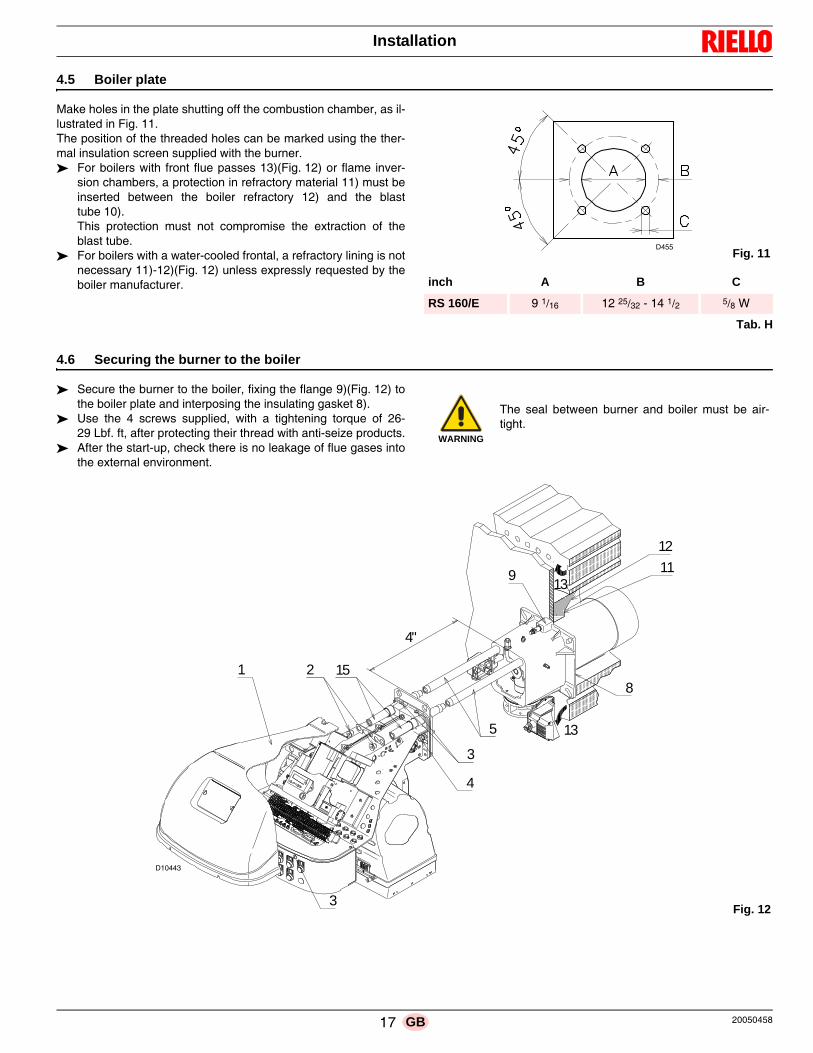
4.5 Boiler plate
Make holes in the plate shutting off the combustion chamber, as il-lustrated in Fig. 11. The position of the threaded holes can be marked using the ther-mal insulation screen supplied with the burner. For boilers with front flue passes 13)(Fig. 12) or flame inver-
sion chambers, a protection in refractory material 11) must beinserted between the boiler refractory 12) and the blasttube 10).This protection must not compromise the extraction of theblast tube.
For boilers with a water-cooled frontal, a refractory lining is notnecessary 11)-12)(Fig. 12) unless expressly requested by theboiler manufacturer.
Tab. H
4.6 Securing the burner to the boiler
Secure the burner to the boiler, fixing the flange 9)(Fig. 12) tothe boiler plate and interposing the insulating gasket 8).
Use the 4 screws supplied, with a tightening torque of 26-29 Lbf. ft, after protecting their thread with anti-seize products.
After the start-up, check there is no leakage of flue gases intothe external environment.
inch A B C
RS 160/E 9 1/16 12 25/32 - 14 1/2 5/8 W
Fig. 11D455
WARNING
The seal between burner and boiler must be air-tight.
4"
913
13
8
12
11
1521
4
3
5
3Fig. 12
D10443
17 20050458GB

Installation
4.7 Electrode positioning
To verify the correct position of the ignition electrode (Fig. 14), youneed to separate the combustion head from the rest of the burner.
Proceed as follows: loosen the 4 screws 3)(Fig. 12) and remove the cover 1); remove the screws 2) from the two sliding bars 5); install the extensions 15) and re-screw the screws 2); remove the two screws 4). Pull back the burner on the sliding bars 5) of about 4”; disconnect the electrode lead, then unthread the burner com-
pletely from the sliding bars; remove the screw 1)(Fig. 13) and extract the inner part 2) of
the head. Check the correct position of ignition electrode, as shown in
Fig. 14. Re-install all components with reverse procedure.
4.8 Combustion head adjustment
Installation operations are now at the stage where the blast tubeand sleeve are secured to the boiler as shown in Fig. 15.
It is now a very simple matter to set up the combustion head, as thisdepends solely on the maximum output developed by the burner.
It is therefore essential to establish this value before proceeding toset up the combustion head.
There are two adjustments to make on the head:– outside air R1 – central air R2
WARNING
Measures must be respected.
1
2
Fig. 13
D10444
1/8"
1"
1/20"Fig. 14
D11020
Fig. 15
D1707
OUTSIDE AIRADJUSTMENT (R1)
CENTRAL AIRADJUSTMENT (R2)
20050458 18 GB

Installation
In diagram (Fig. 16) find the notch for:
Outside air adjustment - R1– Turn screw 4)(Fig. 15) until the notch identified is aligned with
the front surface 5) of the connector.
Central air adjustment - R2– Loosen the 3 screws 1)(Fig. 15) and turn ring 2) until the notch
identified is aligned with index 3). – Tighten the 3 screws 1) fully down.
Example:
Max. burner output = 5681 MBtu/hrIf we consult diagram (Fig. 16) we find that for this output the ad-justments are:– outside air: R1 = notch 8.6;– central air: R2 = notch 0.
NOTE:R2 adjustment (Fig. 16) is an indication only. If possible, always keep the ring nut closed (notch 0); if air recoveryis required the nut may be opened following the indications in dia-gram. Make sure that the combustion characteristics are satisfac-tory and free of pulsations.
Once the combustion head adjustment is completed: push the burner on the sliding bars 3) at approximately 4” from
the pipe coupling 4) - burner in the position shown in Fig. 17; insert the electrode cable, then slide the burner as far as the
pipe coupling - burner in the position shown in Fig. 18; unscrew the 2 screws 2) from the extension 5) and reposition
them as previously Fig. 18. refit the screws 2) on the sliding bars 3); fix the burner to the pipe coupling with the screws 1).
Key Fig. 17 and Fig. 181 Screw2 Screw3 Sliding bars4 Pipe coupling5 Extension sliding bars6 Lifting rings
WARNING
In order to facilitate adjustment, loosen screw6)(Fig. 15), adjust and then tighten.
WARNING
When fitting the burner on the two sliding bars, it isadvisable to gently draw out the high voltage cableuntil it is slightly taut.
Fig. 16
D2801
Not
ch
Burner output
4"
2 5
3
1
4
Fig. 17
D10445
6
5
5
6
6
Fig. 18
D10446
19 20050458GB

Installation
4.9 Gas supply
4.9.1 Gas train
The gas train is type-approved according to standard UL 795 andis supplied separately from the burner.
The gas train can enter the burner from the right or left side, de-pending on which is the most convenient. The gas train must be connected to the gas attachment 1)
(Fig. 19) with the flange 2), the gasket 3) and the screws 4)supplied with the burner.
The gas solenoids must be as close as possible to the burner,to ensure that the gas reaches the combustion head within thesafety time of 3s.
Ensure that the maximum pressure necessary for the burner isincluded in the calibration field of the pressure regulator(colour of the spring).
4.9.2 Gas feeding line
It must be type-approved according to required standards and issupplied separately from the burner.
Key (Fig. 20)1 Gas input pipe2 Manual valve3 Pressure regulator4 Minimum gas pressure switch5 1st safety shut off valve6 2nd safety shut off valve7 Standard issue burner with flange gasket8 Gas adjustment butterfly valve (on the burner)9 Burner10 Maximum gas pressure switch (on the burner)
WARNING
See the accompanying instructions for theadjustment of the gas train.
D722
Fig. 19
Fig. 20
D2438
GAS PILOT LINE
MAIN GAS LINE
20050458 20 GB

Installation
4.10 Gas pressure
The Tab. I shows minimum load losses at combustion head (p1)and gas butterfly valve (p2) depending on the maximum burneroutput operation with natural gas and LPG.
p1 - Gas pressure is measured at the test point 1)(Fig. 21), with:– combustion chamber at 0 mbar– burner working at maximum output– combustion head adjustment as indicated in Fig. 16, page 19.
p2 - Load loss at gas butterfly valve 2)(Fig. 21) with maximumopening: 90°.
NOTETo know the approximate output at which the burner is operating atits maximum:– subtract the combustion chamber pressure from the gas pres-
sure measured at test point 1)(Fig. 21);– find, in the Tab. I the pressure value closest to the result you
want;– read the corresponding output on the left.
Example with natural gas:– Maximum output operation– Gas pressure at test point 1)(Fig. 21) = 4.09“ WC– Pressure in combustion chamber = 1.14“ WC
4.09 - 1.14 = 2.95“ WC
A maximum output of 4166 MBtu/hr shown in Tab. I corresponds to2.95” WC pressure.
This value serves as a rough guide, the effective delivery must bemeasured at the gas meter.
Tab. I
Mbtu/hrp1 ("WC) p1 ("WC) p2 ("WC) p2 ("WC)
Natural Gas LPG Natural Gas LPG
3522 2.20 0.82 0.39 0.15
3787 2.52 0.93 0.43 0.16
4166 2.95 1.09 0.51 0.19
4545 3.39 1.25 0.63 0.23
4924 3.82 1.41 0.75 0.28
5302 4.25 1.57 0.87 0.32
5681 4.69 1.73 0.98 0.36
6060 5.12 1.89 1.10 0.41
6438 5.75 2.13 1.26 0.47
6817 6.50 2.40 1.42 0.52
7044 6.97 2.58 1.50 0.55
Fig. 21
1
2
D2441
21 20050458GB

Installation
4.11 Electrical wiring
Notes on safety for the electrical wiring
Before carrying out any maintenance, cleaning or checking opera-tions:
If the cover is still present, remove it and proceed with the electricalwiring.
All the cables to be connected to the burner are fed through thegrommets. The use of the cable grommets can take various forms.
By way of example we indicate the following mode (according toUL795):1 Three phase power supply with 3/4 inch cable grommet.2 Available: single phase power supply and other devices with
1/2 inch cable grommet.3 Horn4 Available: consents/safety, minimum gas pressure switch, gas
valves and other devices with 3/8 inch cable grommet.5 Anchor plate for installation of step down transformer.6 Available for ground terminals
The electrical wiring must be carried out with the electrical supply disconnected. Electrical wiring must be carried out by qualified personnel and in compliance with the regulations currently in force in
the country of destination. Refer to the electrical layouts. The manufacturer declines all responsibility for modifications or connections different from those shown in the electri-
cal layouts. Check that the electrical supply of the burner corresponds to that shown on the identification label and in this manual. Do not invert the neutral with the phase in the electrical supply line.
Any inversion would cause a lockout due to firing failure. The electrical safety of the device is obtained only when it is correctly connected to an efficient earthing system,
made according to current standards. It is necessary to check this fundamental safety requirement. In the event of doubt, have the electrical systemchecked by qualified personnel. Do not use the gas tubes as an earthing system for electrical devices.
The electrical system must be suitable for the maximum input power of the device,as indicated on the label and in themanual, checking in particular that the section of the cables is suitable for the input power of the device.
For the main power supply of the device from the electricity mains: - do not use adapters, multiple sockets or extensions; - use an omnipolar switch with an opening of at least 1/8 inch (overvoltage category) between the contacts, as indi-
cated by the current safety standards. Do not touch the device with wet or damp body parts and/or in bare feet. Do not pull the electric cables.
DANGER
disconnect the electrical supply from the burner bymeans of the main system switch;
DANGER
close the fuel interception tap;
DANGER
avoid condensate, ice and water leaks from form-ing.
WARNING
The control panel is in compliance with UL508A.
1
2
3
6
6
4
5
6
Fig. 22D10475
20050458 22 GB

Installation
4.12 Thermal relay calibration
Depending on the burner type, there are two different thermal re-lays: – Electro-mechanical termal relay (used for single phase motors)– Electronic thermal relay (used for three phase motors)
4.12.1 Electro-mechanical thermal relay
The electro-mechanical termal relay (Fig. 23) is used to avoid dam-age to the motor owing to a strong increase in absorption or thelack of a phase.
For the calibration, refer to the table given in electrical layout. If theminimum value of the scale of the thermal relay is greater than therating absorption of the motor, protection is still ensured.
This arises when the power supply of the motor is a nominal value. To reset, in the case of an intervention of the thermal relay,
press the button “RESET” (Fig. 23). The button “STOP” (Fig. 23) opens the NC (95-96) contact
and stops the motor.
To test the thermal relay, insert a screwdriver in the window“TEST” (Fig. 24) and move it in the sense of the arrow(towards right).
4.12.2 Electronic thermal relay To reset, in the case of an intervention of the thermal relay,
press the button “RESET” (Fig. 25).
There are two different solution to test the electronic thermal relay: Device test (Fig. 26)
Push slowly the button in the window with a little screwdriver.
Contact test NC (95-96) and NO (97-98)(Fig. 27)Insert in the window a little screwdriver and move it in thesense of the arrow.
WARNING
Automatic resetting can be dangerous.
This action is not provided for the burner oper-ation.
Fig. 23D9273
Fig. 24D9274
Fig. 25
S8109
Fig. 26
S8111
S8111
Fig. 27
S8110
23 20050458GB

Installation
4.13 Motor connection at 208-230 or 460V
WARNING:the motors, manufactured for 208-230/460 IE2/Epact voltage, have a different connection than IE1 motors, no more star/delta but star/double star. Please, pay attention to the indications in case of modification of voltage, maintenance, or substitution.
4.14 Motor connection at 575V
WARNING:the motors, manufactured for 575V IE2/Epact voltage, have the same control box base of the IE1 motors. Please pay attention to the indications in case of maintenance or substitution.
4.15 Reversible direction
WARNING:If it is necessary to reverse the direction then reverse the two main supply phases. For example: L1 with L2, there is not difference between IE1 and IE2/Epact.
D3686IE1 IE2/Epact
U2 V2 W2
U3 V3 W3
U1 V1 W1
S8379
U2 V2 W2
U3 V3 W3
U1 V1 W1
S8380
~ ~ ~ ~ ~ ~460V 208-230V
~ ~ ~ ~ ~ ~460V 208-230V
Fig. 28
S8382
~ ~ ~575V Fig. 29
�� �� ��
�� �� ��
���S8381
L1 L2
Fig. 30
20050458 24 GB
Start-up, calibration and operation of the burner
5.1 Notes on safety for the first start-up
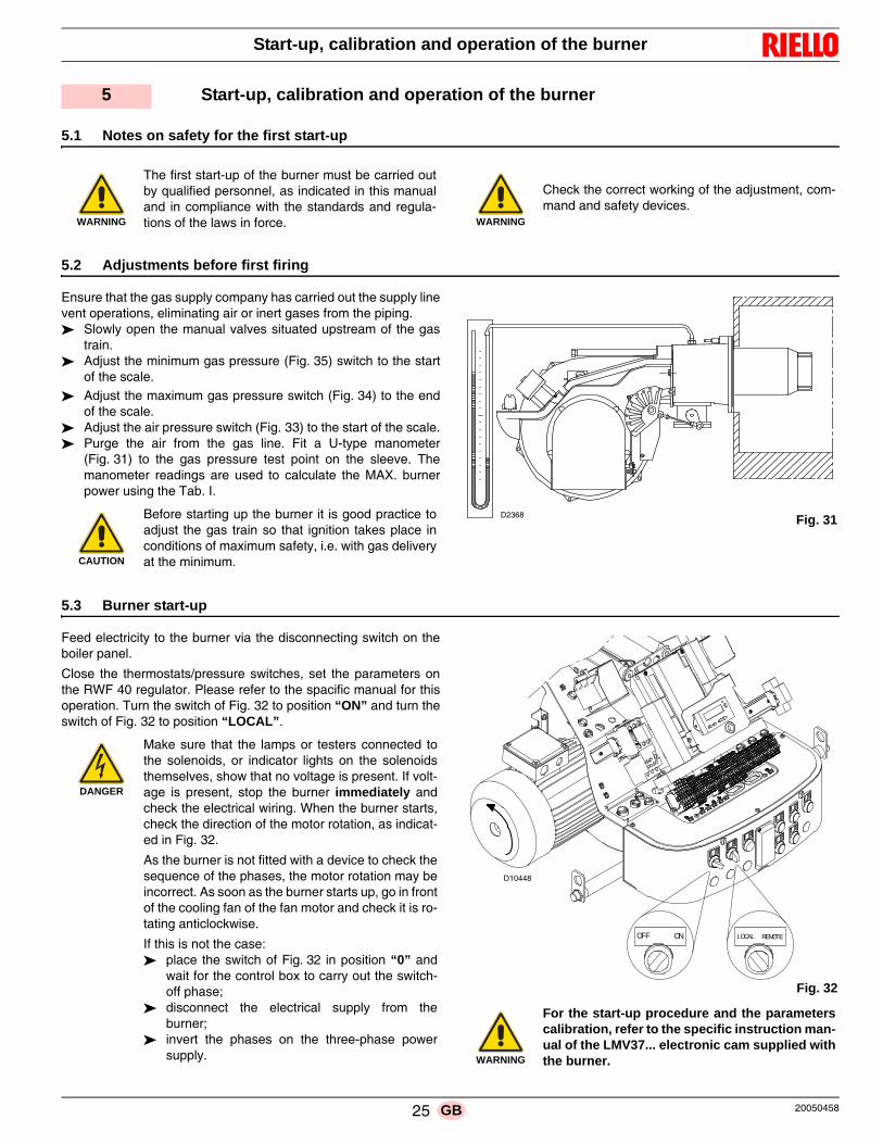
5.2 Adjustments before first firing
Ensure that the gas supply company has carried out the supply linevent operations, eliminating air or inert gases from the piping. Slowly open the manual valves situated upstream of the gas
train. Adjust the minimum gas pressure (Fig. 35) switch to the start
of the scale.
Adjust the maximum gas pressure switch (Fig. 34) to the endof the scale.
Adjust the air pressure switch (Fig. 33) to the start of the scale. Purge the air from the gas line. Fit a U-type manometer
(Fig. 31) to the gas pressure test point on the sleeve. Themanometer readings are used to calculate the MAX. burnerpower using the Tab. I.
5.3 Burner start-up
Feed electricity to the burner via the disconnecting switch on theboiler panel.
Close the thermostats/pressure switches, set the parameters onthe RWF 40 regulator. Please refer to the spacific manual for thisoperation. Turn the switch of Fig. 32 to position “ON” and turn theswitch of Fig. 32 to position “LOCAL”.
5 Start-up, calibration and operation of the burner
WARNING
The first start-up of the burner must be carried outby qualified personnel, as indicated in this manualand in compliance with the standards and regula-tions of the laws in force. WARNING
Check the correct working of the adjustment, com-mand and safety devices.
CAUTION
Before starting up the burner it is good practice toadjust the gas train so that ignition takes place inconditions of maximum safety, i.e. with gas deliveryat the minimum.
Fig. 31D2368
DANGER
Make sure that the lamps or testers connected tothe solenoids, or indicator lights on the solenoidsthemselves, show that no voltage is present. If volt-age is present, stop the burner immediately andcheck the electrical wiring. When the burner starts,check the direction of the motor rotation, as indicat-ed in Fig. 32.
As the burner is not fitted with a device to check thesequence of the phases, the motor rotation may beincorrect. As soon as the burner starts up, go in frontof the cooling fan of the fan motor and check it is ro-tating anticlockwise.
If this is not the case: place the switch of Fig. 32 in position “0” and
wait for the control box to carry out the switch-off phase;
disconnect the electrical supply from theburner;
invert the phases on the three-phase powersupply. WARNING
For the start-up procedure and the parameterscalibration, refer to the specific instruction man-ual of the LMV37... electronic cam supplied withthe burner.
REMOTELOCALONOFF
Fig. 32
D10448
25 20050458GB

Start-up, calibration and operation of the burner
5.4 Combustion air adjustment
Fuel/combustion air must be synchronized with the relevant servo-motors (air and gas) by storing a setting curve by means of theelectronic cam.
To reduce pressure loss and to have a wider adjustment range, itis best to set the servomotor to the maximum output used, as nearto maximum opening (90°) as possible.
On the gas butterfly valve, the fuel’s partial setting adjustmentbased on required output, with the servomotor fully open, is madeby using the pressure stabilizer on the gas train.
With O2 control via the relative kit, follow the instructions aboutcommissioning in the specific handbook for the LMV36.5... instru-ment provided at the Technical Service Training.
5.4.1 Adjusting gas/air delivery Move slowly towards the maximum output (butterfly gas valve
completely open); adjust the required maximum output with the gas pressure sta-
bilizer; adjust the combustion parameters with the air servomotor and
store the maximum combustion point; complete the procedure slowly, synchronizing the combustion
with the two servomotors and storing the different settingpoints.
5.4.2 Air/fuel control and power modulation system
The air/fuel and power modulation system installed on RS burnerseries provides, a set of integrated functions ensuring top level en-ergy and operational performance from the burner, both for singleand grouped burners (e.g. boiler with a double combustion cham-ber or several generators in parallel).
The system includes the following basic functions: air and fuels are supplied in correct quantities by positioning
the valves by direct servo-control, thus avoiding the possibilityof play typical of systems used for traditional modulating burn-ers, in which settings are obtained by levers and a mechanicalcam;
burner power is modulated according to the load required bythe system, while boiler pressure or temperature is maintainedat set operating values;
fine, continuous correction of the airflow according to the anal-ysis of the flue gases at the stack (O2); this function is associ-ated with the O2 kit containing the PLL module and the QGO2sensor;
measurement of the combustion efficiency; this function isassociated with the O2 kit;
a sequence (cascade control) of several boilers by suitablyconnecting different units.
Further interfaces and computer communication functions for re-mote control or integration in centrally supervised systems areavailable according to the system’s configuration.
NOTE
The first start-up and all further operations concerning internal set-tings of the control system or expansion of basic functions, are ac-cessed with a password and are reserved for technical servicepersonnel specifically trained for internal programming of the in-strument and for the specific application obtained with this burner.
The first start-up and curve synchronization manual is supplied withthe burner.
The complete manual for checking and setting all parameters willbe provided on application.
5.5 Final calibration of the pressure switches
5.5.1 Air pressure switch
The air pressure switch is connected in differential (see Fig. 33)and is activated by both the negative pressure of the air intake andthe air pressure from the fan.
Adjust the air pressure switch after having performed all other burn-er adjustments with the air pressure switch set to the min. of thescale.
With the burner operating at low fire, adjust the pressure switch byslowly turning the relative knob clockwise until the burner locks out.
Then turn the knob counter-clockwise about 20% of the set pointand start-up the burner again to ensure the set point is correct.
If the burner locks out again, turn the knob counter-clockwise a littlebit more.
Fig. 3320048352
20050458 26 GB

Start-up, calibration and operation of the burner
5.5.2 Maximum gas pressure switch
Adjust the maximum gas pressure switch (Fig. 34) after having per-formed all other burner adjustments with the maximum gas pres-sure switch set to the end of the scale.
With the burner operating at MAX output, reduce the adjustmentpressure by slowly turning the adjustment dial anticlockwise untilthe burner locks out.
Then turn the dial clockwise by 0.8” WC and repeat burner firing.
If the burner locks out again, turn the dial again clockwise by0.4” WC.
5.5.3 Minimum gas pressure switch
Adjust the minimum gas pressure switch (Fig. 35) after having per-formed all the other burner adjustments with the pressure switchset at the start of the scale.
With the burner operating at MAX output, increase adjustmentpressure by slowly turning the relative dial clockwise until the burn-er locks out.
Then turn the dial anti-clockwise by 0.8” WC and repeat burnerstarting to ensure it is uniform.
If the burner locks out again, turn the dial anti-clockwise again by0.4” WC.
5.6 Flame signal measurement
Check the flame signal through the parameter 954, as indicated inFig. 36. The displayed value is expressed in percentage.
The value during the operation must be higher than 24%. If at theburner start-up the value is higher or equal of 18%, the burner locksout due to the extraneous light.
For further and specific information, please refer to the specificinstruction manual. The display (Fig. 36) shows parameter 954:flashing on the left.
On the right, the flame’s intensity is displayed as a percentage. Example: 954: 0.0
5.7 Final checks (with the burner working)
Fig. 34D9272
Fig. 35D9290
S8171
P
V h min s %
Fig. 36
Open the control limit operation Open the high limit operation The burner must stop
Rotate the maximum gas pressure switch knob to the mini-mum end-of-scale position
Rotate the air pressure switch knob to the maximum end ofscale position
The burner must stop in lockout
Switch off the burner and disconnect the voltage Disconnect the minimum gas pressure switch The burner must not start
Cover the UV flame sensorThe burner must stop in lockout due to firing failure
WARNING
Make sure that the mechanical locking systems onthe different adjustment devices are fully tightened.
27 20050458GB

Maintenance
6.1 Notes on safety for the maintenance
The periodic maintenance is essential for the good operation, safe-ty, yield and duration of the burner.
It allows you to reduce consumption and polluting emissions and tokeep the product in a reliable state over time.
Before carrying out any maintenance, cleaning or checking opera-tions:
6.2 Maintenance programme
6.2.1 Maintenance frequency
The combustion system should be checked at least once a yearby a representative of the manufacturer or another specialisedtechnician.
6.2.2 Checking and cleaning
CombustionThe optimum calibration of the burner requires an analysis of theflue gases. Significant differences with respect to the previousmeasurements indicate the points where more care should be ex-ercised during maintenance.
Combustion headOpen the burner and make sure that all components of the com-bustion head are in good condition, not deformed by the hightemperatures, free of impurities from the surroundings and cor-rectly positioned.
FanCheck to make sure that no dust has accumulated inside the fan oron its blades, as this condition will cause a reduction in the air flowrate and provoke polluting combustion.
BurnerClean the outside of the burner.Clean and grease the cam variable profile.
BoilerClean the boiler as indicated in its accompanying instructions in or-der to maintain all the original combustion characteristics intact, es-pecially the flue gas temperature and combustion chamberpressure.
Gas leaksMake sure that there are no gas leaks on the pipework between thegas meter and the burner.
Gas filterChange the gas filter when it is dirty.
UV scanner
In order to reach the UV scanner (Fig. 37), proceed as follows: extract the UV scanner 2); clean the glass cover from any dust that may have accumu-
lated.
CombustionIn case the combustion values found at the beginning of the inter-vention do not respect the standards in force or, in any case, do notcorrespond to a proper combustion, contact the Technical Assis-tant and have him carry out the necessary adjustments.
6 Maintenance
DANGER
The maintenance interventions and the calibrationof the burner must only be carried out by qualified,authorised personnel, in accordance with the con-tents of this manual and in compliance with thestandards and regulations of current laws.
DANGER
Disconnect the electricity supply from the burner bymeans of the main switch of the system.
DANGER
Close the fuel interception tap.
WARNING
Be extremely careful while troubleshooting thedetector; line voltage is present on some of theterminals when power is on.
Open the master switch to disconnect powerbefore removing or installing the detector.
2
Fig. 37D10628
20050458 28 GB
Maintenance
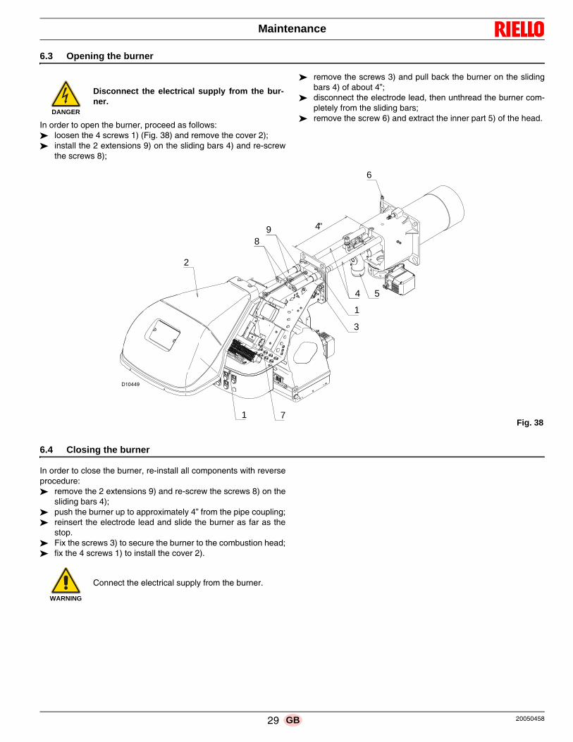
6.3 Opening the burner
In order to open the burner, proceed as follows: loosen the 4 screws 1) (Fig. 38) and remove the cover 2); install the 2 extensions 9) on the sliding bars 4) and re-screw
the screws 8);
remove the screws 3) and pull back the burner on the slidingbars 4) of about 4”;
disconnect the electrode lead, then unthread the burner com-pletely from the sliding bars;
remove the screw 6) and extract the inner part 5) of the head.
6.4 Closing the burner
In order to close the burner, re-install all components with reverseprocedure: remove the 2 extensions 9) and re-screw the screws 8) on the
sliding bars 4); push the burner up to approximately 4” from the pipe coupling; reinsert the electrode lead and slide the burner as far as the
stop. Fix the screws 3) to secure the burner to the combustion head; fix the 4 screws 1) to install the cover 2).
DANGER
Disconnect the electrical supply from the bur-ner.
2
89
4
1
3
5
6
1
4"
7Fig. 38
D10449
WARNING
Connect the electrical supply from the burner.
29 20050458GB

Appendix - Spare parts
A Appendix - Spare parts
20050458 30 GB

Appendix - Spare parts
N. CODE
460V
575V DESCRIPTION BURNER SERIAL NUMBER
1 3014083 • • AIR DAMPER ASSEMBLY 02413xxxxxx
1 20073258 • • AIR DAMPER ASSEMBLY 02423xxxxxx
2 3013683 • • GRID
3 3013682 • • SOUND DAMPING C
4 3003763 • • INSPECTION WINDOW
5 3013686 • • BAR EXTENSIONS
6 3012976 • • FAN C
7 20037259 • • COVER
8 20026784 • • INSPECTION WINDOW
9 20014366 • • FUSE HOLDER C
10 3013093 • • SUPPORT
11 20031413 • • HORN C
12 20027018 • • RED SIGNAL LIGHT C
13 20027020 • • YELLOW SIGNAL LIGHT C
14 20027021 • • COMMUTATOR C
15 3012971 • • FLANGE AND ELBOW
16 3005482 • • SEAL C
17 20010967 • • AZL DISPLAY B
18 20010968 • • ELECTRONIC CAM C
19 20031411 • • RWF 40 POWER REGULATOR C
20 3013940 • • CONNECTORS ASSEMBLY C
21 20031014 • MOTOR C
21 20028330 • MOTOR C
22 3006211 • • FUSE 6.3A A
23 20027013 • • GREEN SIGNAL LIGHT C
24 20013973 • CONTACTOR C
24 20028310 • CONTACTOR C
25 20027014 • • WHITE SIGNAL LIGHT C
26 3013681 • • SCREW C
27 3014081 • • BRACKET
28 3014079 • • SPACER
29 20027917 • OVERLOAD TERMAL RELAY C
29 20028312 • OVERLOAD TERMAL RELAY C
30 3012393 • • ELECTRODE CONNECTION A
31 3013091 • • ELECTRODE A
32 20008601 • • SERVOMOTOR B
33 3012631 • • TUBE
34 3012633 • • DISTRIBUTOR
35 3013939 • • INDEX
36 3012634 • • INTERIOR TUBE
37 3013090 • • GAS PILOT
38 3013094 • • EXTERIOR TUBE
39 3012637 • • ELBOW
40 20027422 • • COMMUTATOR C
41 3012088 • • CONNECTOR C
42 3003891 • • CONNECTOR
*
31 20050458GB
Appendix - Spare parts
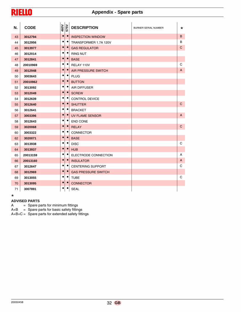
*ADVISED PARTSA = Spare parts for minimum fittingsA+B = Spare parts for basic safety fittingsA+B+C = Spare parts for extended safety fittings
43 3012794 • • INSPECTION WINDOW B
44 3012956 • • TRANSFORMER 1.7A 120V B
45 3013977 • • GAS REGULATOR C
46 3012014 • • RING NUT
47 3012841 • • BASE
48 20010969 • • RELAY 110V C
49 3012948 • • AIR PRESSURE SWITCH A
50 3003643 • • PLUG
51 20010962 • • BUTTON
52 3013092 • • AIR DIFFUSER
53 3012049 • • SCREW
54 3012639 • • CONTROL DEVICE
55 3012640 • • SHUTTER C
56 3012641 • • BRACKET
57 3003396 • • UV FLAME SENSOR A
58 3012643 • • END CONE
59 3020068 • • RELAY C
60 3003322 • • CONNECTOR
62 3020071 • • BASE
63 3013938 • • DISC C
64 3013937 • • HUB
65 20013159 • • ELECTRODE CONNECTION A
66 20013160 • • INSULATOR A
67 3012647 • • CENTERING SUPPORT C
68 3012969 • • GAS PRESSURE SWITCH
69 3013055 • • TUBE C
70 3013095 • • CONNECTOR
71 3007891 • • SEAL
N. CODE
460V
575V DESCRIPTION BURNER SERIAL NUMBER *
20050458 32 GB

Appendix - Accessories
Gas train according to UL Standards
B Appendix - Accessories
WARNING
The installer is responsible for the supply and instal-lation of any required safety device(s) not indicatedin this manual.
33 20050458GB

Appendix - Burner start up report
C Appendix - Burner start up report
Model number: Serial number:Project name: Start-up date:
Installing contractor: Phone number:
Model number: Serial number:
Project name: Start-up date:
Installing contractor: Phone number:
GAS OPERATION
Gas Supply Pressure: CO2: Low Fire High Fire
Main Power Supply: O2: Low Fire High Fire
Control Power Supply: CO: Low Fire High Fire
Burner Firing Rate: NOX: Low Fire High Fire
Manifold Pressure: Net Stack Temp - Low Fire: High Fire
Pilot Flame Signal: Comb. Efficiency - Low Fire: High Fire
Low Fire Flame Signal: Overfire Draft:
High Fire Flame Signal:
CONTROL SETTINGS
Operating Setpoint: Low Oil Pressure:
High Limit Setpoint: High Oil Pressure:
Low Gas Pressure:Flame Safeguard Model Number:
High Gas Pressure: Modulating Signal Type:
NOTES
20050458 34 GB


Subject to modifications
RIELLO BURNERS NORTH AMERICA
35 Pond Park Road 1-800-4-RIELLO 2165 Meadowpine Blvd
Hingham, Massachusetts, 1-800-474-3556 Mississauga, Ontario
U.S.A. 02043 Canada L5N 6H6
http://www.riello.ca
RIELLO S.p.A.
I-37045 Legnago (VR)
Tel.: +39.0442.630111
http:// www.riello.it
http:// www.riello.com


![[XLS] · Web viewHeating boilers - Test code for heating boilers for atomizing oil burners Heating boilers - Part 2: Heating boilers with forced draught burners - Special requirements](https://static.fdocuments.net/doc/165x107/5aa92e707f8b9a72188c8d49/xls-viewheating-boilers-test-code-for-heating-boilers-for-atomizing-oil-burners.jpg)