
Force Measurement Solutions - NOSHOK · Force Measurement Solutions Mechanical Hydraulic Load Cells...
44
Force Measurement Solutions Mechanical Hydraulic Load Cells Electronic Tension & Compression Transducers S-Type Tension & Compression Transducers Custom Force Sensors Test Kits
-
Upload
nguyenkhanh -
Category
Documents
-
view
219 -
download
0
Transcript of Force Measurement Solutions - NOSHOK · Force Measurement Solutions Mechanical Hydraulic Load Cells...
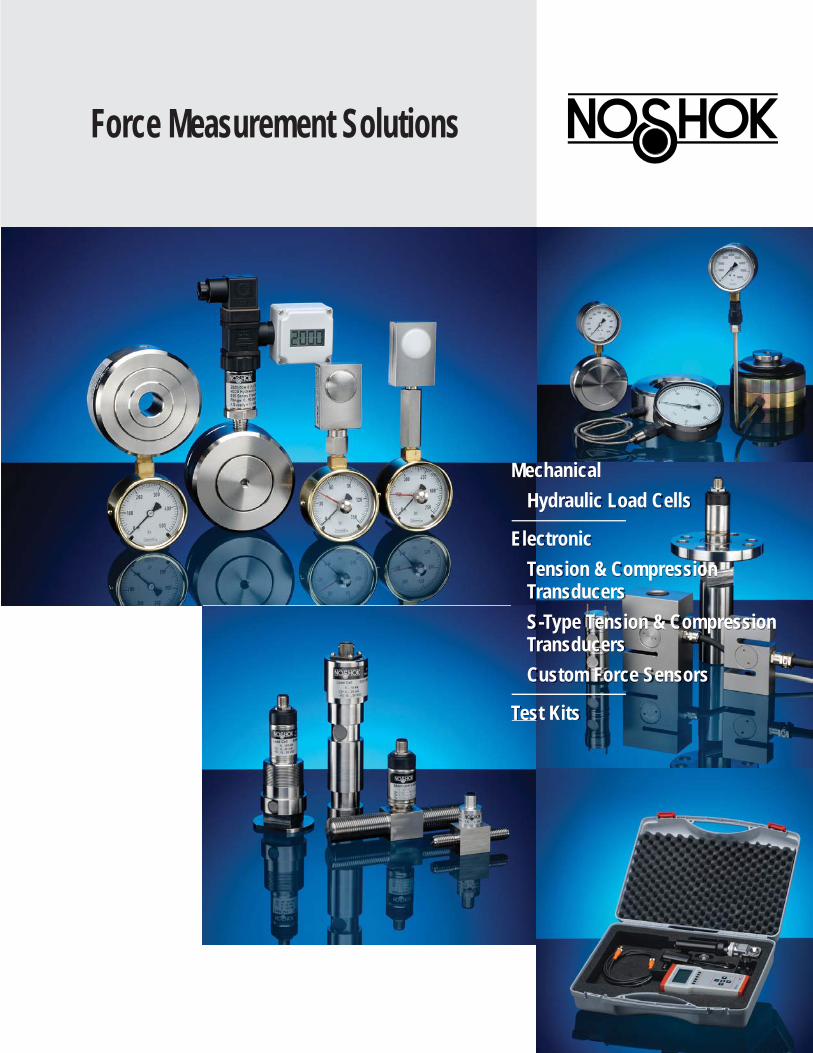
Force Measurement Solutions
Mechanical Hydraulic Load Cells
Electronic Tension & Compression Transducers S-Type Tension & Compression Transducers Custom Force Sensors
Test Kits

NOSHOK is an ISO 9001:2015 registered company.
NOSHOK is a member and actively supports:
At NOSHOK, we pride ourselves on being innovators in the industry by continually offering the latest technology and measurement solutions, and providing the best customer support in the marketplace.
Established in 1967, NOSHOK was one of the fi rst companies to offer liquid fi lled pressure gauges. We also took a bold step by backing our quality gauges with an extended 3-year warranty. That unwavering standard of quality has endured for 50+ years, and as we have expanded our product offering we continue to provide industry-leading warranties. NOSHOK also leads the industry as one of the fi rst companies to offer corrosion-resistant zinc nickel plating standard on our carbon steel valves.
We have the capacity to put together special requirements which are so often hard to fi nd. If you do not fi nd what you need in this catalog, chances are we can still put a solution together.
NOSHOK is committed to providing excellence on every level. Thank you for choosing NOSHOK products.
Jeff N. ScottPresident
NOSHOK Corporate HeadquartersYour Single Source Instrumentation Company

3
WARRANTY INFORMATIONNOSHOK’s One Year Warranty applies to all NOSHOK force measurement products, and all options & accessories listed in this catalog.
NOSHOK guarantees all products to be free from defects in material and workmanship and to operate within the catalogued performance specifi cations. These products must be operated within the cataloged environmental and application parameters. Determination of failure will be made by NOSHOK, Inc.’s equipment and personnel or a certifi ed test facility specializing in this type of evaluation. Instrument failures determined to be caused by over-range, incompatibility with environment or product media and abuse will not be considered under this warranty. NOSHOK, Inc. will, at its discretion, repair or replace the working parts of the damaged gauge without cost to the customer.
T A B L E O F C O N T E N T S
6 cm2 Nominal Diameter Hydraulic Load Cell: 1000 SERIES .............................................................................................................................................................................................. 4-7
20 cm2 Nominal Diameter Hydraulic Load Cell: 2000 SERIES ............................................................................................................................................................................................ 8-11
80 cm2 Nominal Diameter Hydraulic Load Cell: 3000 SERIES ...........................................................................................................................................................................................12-15
10 cm2, 40 cm2, 100 cm2, 250 cm2 Nominal Diameter Hydraulic Load Cell: 4000 SERIES .......................................................................................................................................................................................... 16-19
40 cm2, 60 cm2, 90 cm2, 160 cm2, 240 cm2, 410 cm2 Nominal Diameter Hydraulic Load Cell: 5000 SERIES ..........................................................................................................................................................................................20-23
Tension & Compression Force Transducer: 3540 SERIES ......................................................................................................................................................................................... 24-27
S-Type Tension & Compression Force Transducer: 2351 SERIES ........................................................................................................................................................................................... 28-29
Custom Force Sensors .........................................................................................................................................................................30-31
Chain Hoist:3010 SERIES .......................................................................................................................................................................................... 32-33
Weld Force:3020 SERIES ..........................................................................................................................................................................................34-35
Reference Information ......................................................................................................................................................................................36-41
MECHANICAL FORCE MEASUREMENT
ELECTRONIC FORCE MEASUREMENT
In keeping with and for purpose of product and/or manufacturing process improvements, NOSHOK, Inc. reserves the right to make design changes without prior notice.
TEST KITS

4
• Compact fl at body design for compression force measurement• Ranges from 150 lbf to 7,000 lbf• Accuracy levels range from ±0.125% full scale (BFSL) to ±1.5% full scale, depending on the measuring instrument• Durable stainless steel housing and piston provide exceptional corrosion resistance and durability• A high quality NOSHOK 300 Series pressure gauge or 100, 200 or 615 Series transducer is directly mounted to the load cell for precise measurement indication• Operates without an external power supply when using a pressure gauge for indication• Provides an extremely high degree of accuracy because the load cell is vacuum fi lled and sealed, eliminating the error that can be caused by entrapped air • Steel jacketed fl exible tubing and capillary systems are offered to accommodate applications that require remote mounting of the gauge or transducer• An optional liquid fi lled gauge dampens the effects of pulsation, vibration and shock, and lubricates the gauge internals for extended service life• Various output signals available in transducer models that are CE compliant
M e c h a n i c a l F o r c e M e a s u r e m e n t
6 cm2 Nominal Diameter Hydraulic Load Cell
SPECIFICATIONSNominal diameter ND 6Load cell housing Stainless steel Piston 6 cm2 Stainless steel
Optional plastic for welding brackets Max piston stroke 0.02” (0.5 mm)Connecting type Connecting spacer, 50 mm - standard
Connecting spacer, 100 mm - optionalFlexible tubing with spiral steel jacket - optional (Max. length 1 m)
Gauge ll uid GlycerinOthers available upon request
Load cell ll SiliconeOperating temperature 14 °F to 122 °F (-10 °C to 50 °C) Ambient temperature -4 °F to 140 °F (-20 °C to 60 °C)
Spot welding Control the forces of the stamp on printing machines Control the forces between rollers on printing equipment Measure and control the forces between welding tongs on spot welding machines Control systems Robotic equipment Production lines Testing equipment
APPLICATIONS
SERIES
5
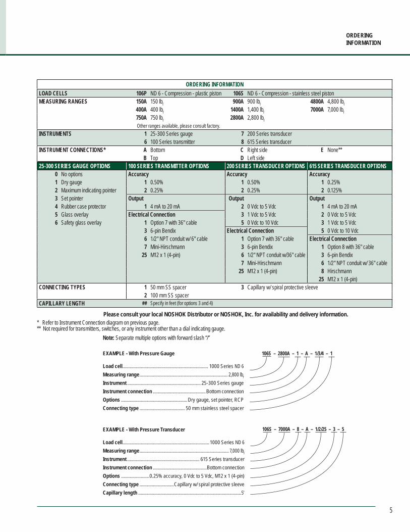
ORDERING INFORMATIONLOAD CELLS 106P ND 6 - Compression - plastic piston 106S ND 6 - Compression - stainless steel piston MEASURING RANGES 150A 150 lbf 900A 900 lbf 4800A 4,800 lbf
400A 400 lbf 1400A 1,400 lbf 7000A 7,000 lbf750A 750 lbf 2800A 2,800 lbfOther ranges available, please consult factory.
INSTRUMENTS 1 25-300 Series gauge 7 200 Series transducer6 100 Series transmitter 8 615 Series transducer
INSTRUMENT CONNECTIONS* A Bottom C Right side E None**B Top D Left side
25-300 SERIES GAUGE OPTIONS 100 SERIES TRANSMITTER OPTIONS 200 SERIES TRANSDUCER OPTIONS 615 SERIES TRANSDUCER OPTIONS0 No options Accuracy Accuracy Accuracy1 Dry gauge 1 0.50% 1 0.50% 1 0.25%2 Maximum indicating pointer 2 0.25% 2 0.25% 2 0.125%3 Set pointer Output Output Output4 Rubber case protector 1 4 mA to 20 mA 2 0 Vdc to 5 Vdc 1 4 mA to 20 mA5 Glass overlay Electrical Connection 3 1 Vdc to 5 Vdc 2 0 Vdc to 5 Vdc6 Safety glass overlay 1 Option 7 with 36" cable 5 0 Vdc to 10 Vdc 3 1 Vdc to 5 Vdc
3 6-pin Bendix Electrical Connection 5 0 Vdc to 10 Vdc6 1/2" NPT conduit w/ 6" cable 1 Option 7 with 36" cable Electrical Connection7 Mini-Hirschmann 3 6-pin Bendix 1 Option 8 with 36" cable
25 M12 x 1 (4-pin) 6 1/2" NPT conduit w/36" cable 3 6-pin Bendix7 Mini-Hirschmann 6 1/2" NPT conduit w/ 36" cable
25 M12 x 1 (4-pin) 8 Hirschmann 25 M12 x 1 (4-pin)
CONNECTING TYPES 1 50 mm SS spacer 3 Capillary w/ spiral protective sleeve2 100 mm SS spacer
CAPILLARY LENGTH ## Specify in feet (for options 3 and 4)
Please consult your local NOSHOK Distributor or NOSHOK, Inc. for availability and delivery information.
Note: Separate multiple options with forward slash “/”
EXAMPLE - With Pressure Gauge
Load cell ...................................................................... 1000 Series ND 6Measuring range ........................................................................ 2,800 lbf
Instrument ............................................................ 25-300 Series gaugeInstrument connection ...........................................Bottom connectionOptions ...................................................... Dry gauge, set pointer, RCPConnecting type ..................................... 50 mm stainless steel spacer
106S – 2800A – 1 – A – 1/3/4 – 1
EXAMPLE - With Pressure Transducer
Load cell ....................................................................... 1000 Series ND 6Measuring range ......................................................................... 7,000 lbf
Instrument ........................................................... 615 Series transducerInstrument connection ............................................Bottom connectionOptions .......................0.25% accuracy, 0 Vdc to 5 Vdc, M12 x 1 (4-pin)Connecting type ............................Capillary w/ spiral protective sleeveCapillary length ....................................................................................5′
106S – 7000A – 8 – A – 1/2/25 – 3 – 5
ORDERINGINFORMATION
* Refer to Instrument Connection diagram on previous page.** Not required for transmitters, switches, or any instrument other than a dial indicating gauge.

6
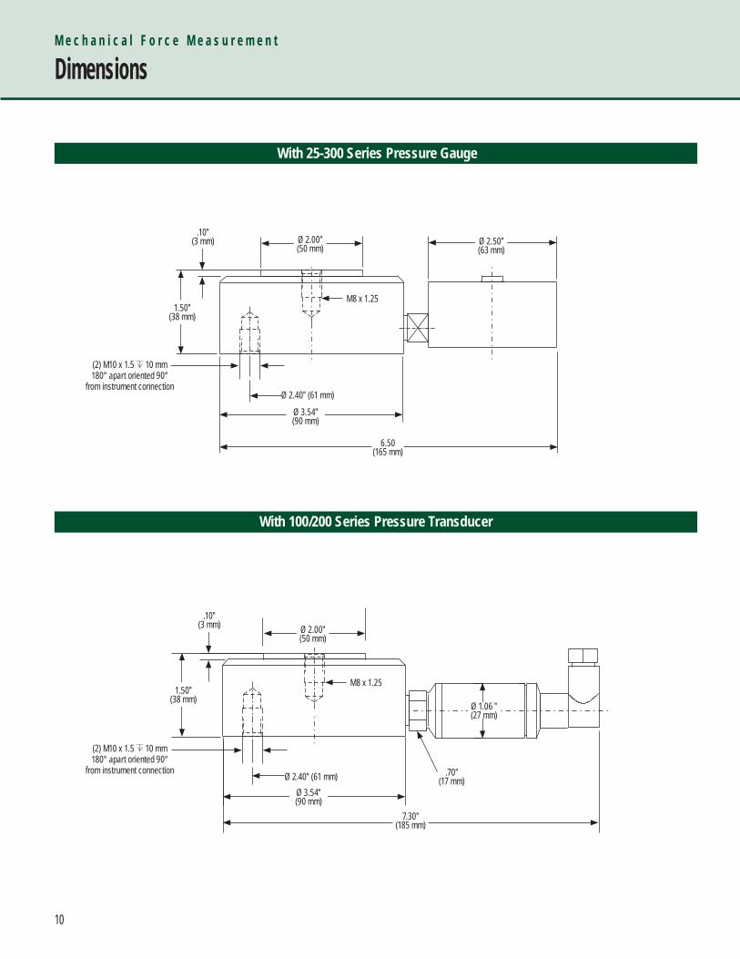
M e c h a n i c a l F o r c e M e a s u r e m e n t
Dimensions
With 25-300 Series Pressure Gauge
Ø 2.50″(63 mm)
.10″ (3 mm)
2.20″(56 mm)
.80″(21 mm)
7.00″(178 mm)
REF
1.40″(36 mm)
Ø 1.00″(25 mm)Piston
50 mm Spacer
7
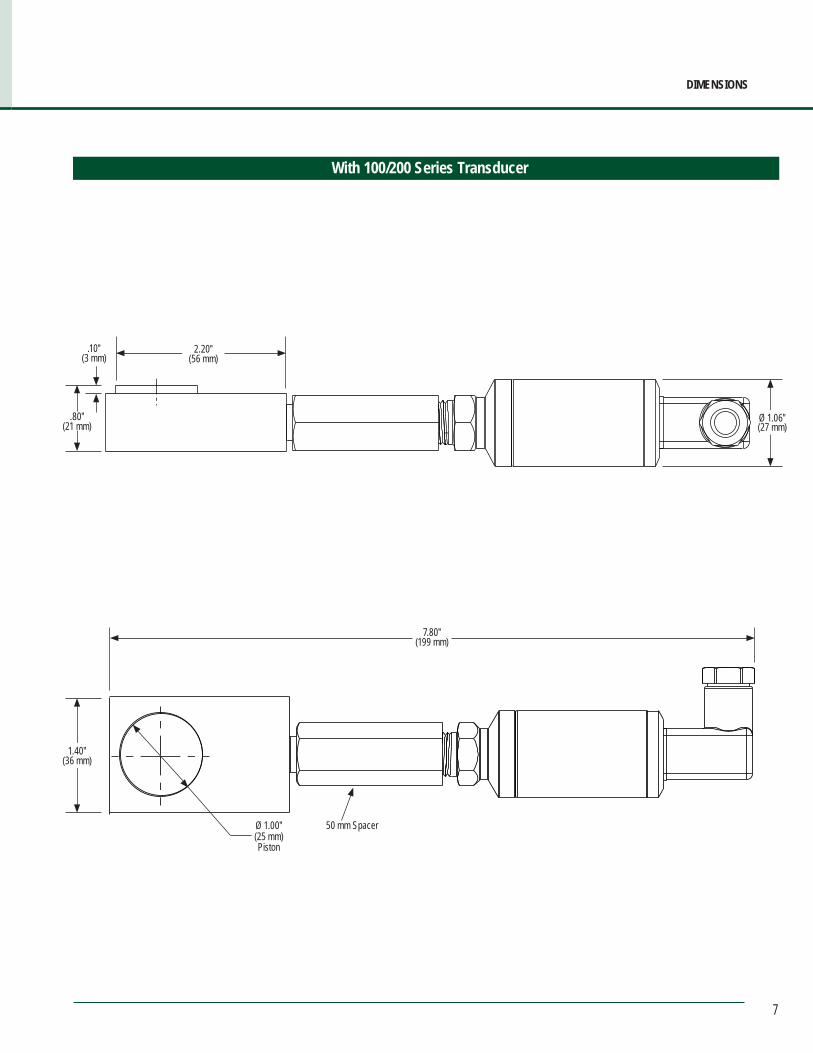
DIMENSIONS
With 100/200 Series Transducer
.10″(3 mm)
7.80″(199 mm)
.80″ (21 mm)
50 mm Spacer
2.20″(56 mm)
Ø 1.06″ (27 mm)
Ø 1.00″(25 mm)Piston
1.40″ (36 mm)

8
• Designed for measuring axial loads and bearing forces• Standard or ring design fi ts most applications• Ranges from 90 lbf to 22,000 lbf• Accuracy levels range from ±0.125% full scale (BFSL) to ±1.5% full scale, depending on the measuring instrument• Durable stainless steel housing and piston provide exceptional corrosion resistance and durability• A high quality NOSHOK 300 or 901 Series pressure gauge or 100, 200 or 615 Series transducer is directly mounted to the load cell for precise measurement indication• Operates without an external power supply when using a pressure gauge for indication• Provides an extremely high degree of accuracy because the load cell is vacuum fi lled and sealed, eliminating the error that can be caused by entrapped air • Steel jacketed fl exible tubing and capillary systems are offered to accommodate applications that require remote mounting of the gauge or transducer• An optional liquid fi lled gauge dampens the effects of pulsation, vibration and shock,and lubricates the gauge internals for extended service life• Various output signals available in transducer models that are CE compliant
M e c h a n i c a l F o r c e M e a s u r e m e n t
20 cm2 Nominal Diameter Hydraulic Load Cell
SPECIFICATIONSNominal diameter ND 20Load cell housing Stainless steel Piston 20 cm2 stainless steel Max piston stroke 0.02" (0.5 mm)Connecting type Direct (standard)
Flexible tubing with spiral steel jacket - optional (max. length 2 m)Capillary restrictor (optional)
Gauge ll uid GlycerinOthers available upon request
Load cell ll SiliconeOperating temperature -4 °F to 140 °F (-20 °C to 60 °C) Ambient temperature -4 °F to 140 °F (-20 °C to 60 °C)
Turning and drilling machines Extruders Measuring and test equipment Production lines Overload protection Vices Control systems and machine tools
APPLICATIONS
SERIES
9
ORDERINGINFORMATION
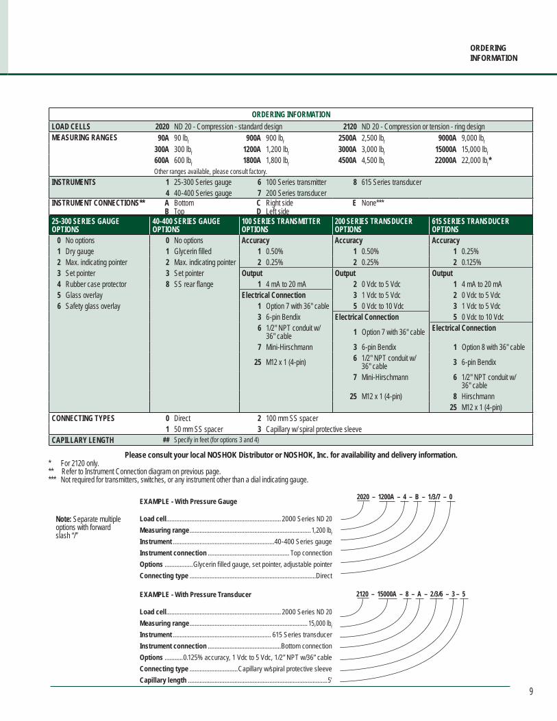
ORDERING INFORMATIONLOAD CELLS 2020 ND 20 - Compression - standard design 2120 ND 20 - Compression or tension - ring design MEASURING RANGES 90A 90 lbf 900A 900 lbf 2500A 2,500 lbf 9000A 9,000 lbf
300A 300 lbf 1200A 1,200 lbf 3000A 3,000 lbf 15000A 15,000 lbf600A 600 lbf 1800A 1,800 lbf 4500A 4,500 lbf 22000A 22,000 lbf*Other ranges available, please consult factory.
INSTRUMENTS 1 25-300 Series gauge 6 100 Series transmitter 8 615 Series transducer4 40-400 Series gauge 7 200 Series transducer
INSTRUMENT CONNECTIONS** A Bottom C Right side E None***B Top D Left side
25-300 SERIES GAUGE OPTIONS
40-400 SERIES GAUGE OPTIONS
100 SERIES TRANSMITTEROPTIONS
200 SERIES TRANSDUCEROPTIONS
615 SERIES TRANSDUCEROPTIONS
0 No options 0 No options Accuracy Accuracy Accuracy1 Dry gauge 1 Glycerin filled 1 0.50% 1 0.50% 1 0.25%2 Max. indicating pointer 2 Max. indicating pointer 2 0.25% 2 0.25% 2 0.125%3 Set pointer 3 Set pointer Output Output Output4 Rubber case protector 8 SS rear flange 1 4 mA to 20 mA 2 0 Vdc to 5 Vdc 1 4 mA to 20 mA5 Glass overlay Electrical Connection 3 1 Vdc to 5 Vdc 2 0 Vdc to 5 Vdc6 Safety glass overlay 1 Option 7 with 36" cable 5 0 Vdc to 10 Vdc 3 1 Vdc to 5 Vdc
3 6-pin Bendix Electrical Connection 5 0 Vdc to 10 Vdc6 1/2" NPT conduit w/
36" cable 1 Option 7 with 36" cable Electrical Connection
7 Mini-Hirschmann 3 6-pin Bendix 1 Option 8 with 36" cable
25 M12 x 1 (4-pin) 6 1/2" NPT conduit w/ 36" cable 3 6-pin Bendix
7 Mini-Hirschmann 6 1/2" NPT conduit w/ 36" cable
25 M12 x 1 (4-pin) 8 Hirschmann 25 M12 x 1 (4-pin)
CONNECTING TYPES 0 Direct 2 100 mm SS spacer1 50 mm SS spacer 3 Capillary w/ spiral protective sleeve
CAPILLARY LENGTH ## Specify in feet (for options 3 and 4)
Please consult your local NOSHOK Distributor or NOSHOK, Inc. for availability and delivery information.
Note: Separate multiple options with forward slash “/”
EXAMPLE - With Pressure Gauge
Load cell ..................................................................... 2000 Series ND 20Measuring range .........................................................................1,200 lbf
Instrument .............................................................40-400 Series gaugeInstrument connection ................................................. Top connectionOptions .................Glycerin filled gauge, set pointer, adjustable pointerConnecting type ............................................................................Direct
2020 – 1200A – 4 – B – 1/3/7 – 0
EXAMPLE - With Pressure Transducer
Load cell ..................................................................... 2000 Series ND 20Measuring range ....................................................................... 15,000 lbf
Instrument ........................................................... 615 Series transducerInstrument connection ............................................Bottom connectionOptions ...........0.125% accuracy, 1 Vdc to 5 Vdc, 1/2” NPT w/36” cableConnecting type .............................Capillary w/spiral protective sleeveCapillary length ....................................................................................5′
2120 – 15000A – 8 – A – 2/3/6 – 3 – 5
* For 2120 only.** Refer to Instrument Connection diagram on previous page.*** Not required for transmitters, switches, or any instrument other than a dial indicating gauge.
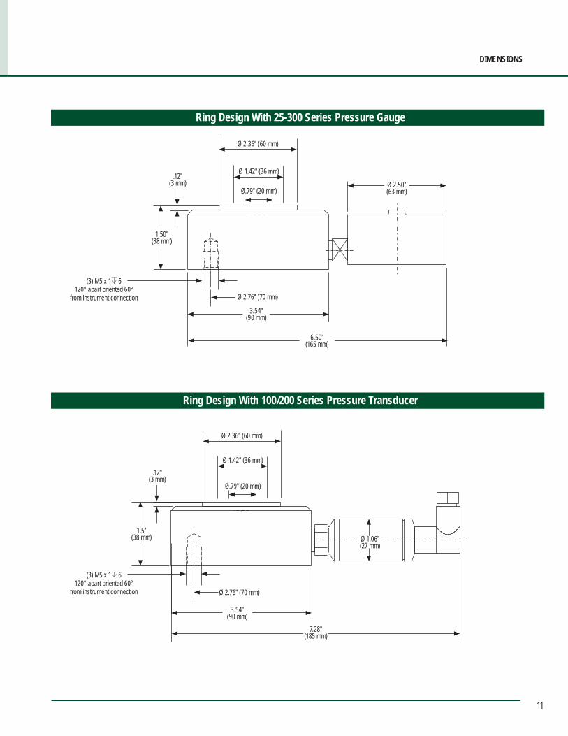
10
M e c h a n i c a l F o r c e M e a s u r e m e n t
Dimensions
With 100/200 Series Pressure Transducer
With 25-300 Series Pressure Gauge
2″50 mmØ 2.00″(50 mm)
Ø 2.50″(63 mm)
.10″(3 mm)
1.50″(38 mm)
M8 x 1.25
Ø 2.40″ (61 mm)
Ø 3.54″(90 mm)
6.50(165 mm)
2″50 mmØ 2.00″(50 mm)
7.30″(185 mm)
1.50″(38 mm)
M8 x 1.25
Ø 2.40″ (61 mm)Ø 3.54″(90 mm)
Ø 1.06 ″(27 mm)
.70″(17 mm)
.10″(3 mm)
(2) M10 x 1.5 10 mm 180° apart oriented 90°
from instrument connection
(2) M10 x 1.5 10 mm 180° apart oriented 90°
from instrument connection
11
DIMENSIONS
Ring Design With 25-300 Series Pressure Gauge
Ring Design With 100/200 Series Pressure Transducer
Ø 2.76″ (70 mm)
3.54″ (90 mm)
6.50″ (165 mm)
.12″(3 mm)
1.50″(38 mm)
Ø 2.50″ (63 mm)
Ø 2.36″ (60 mm)
Ø 1.42″ (36 mm)
Ø.79″ (20 mm)
Ø 2.76″ (70 mm)
3.54″(90 mm)
.12″(3 mm)
1.5″(38 mm)
7.28″(185 mm)
Ø 1.06″(27 mm)
Ø 2.36″ (60 mm)
Ø 1.42″ (36 mm)
Ø.79″ (20 mm)
(3) M5 x 1 6 120° apart oriented 60°
from instrument connection
(3) M5 x 1 6 120° apart oriented 60°
from instrument connection
12
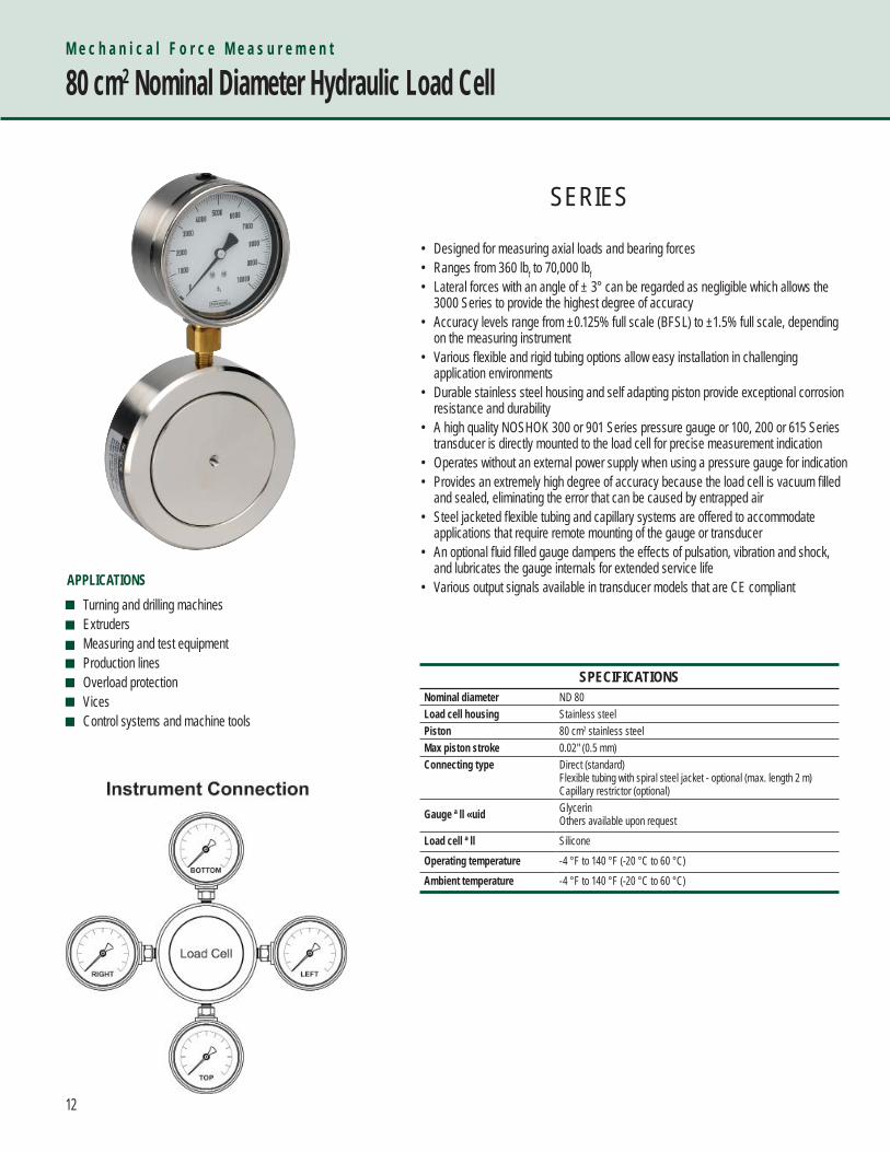
• Designed for measuring axial loads and bearing forces• Ranges from 360 lbf to 70,000 lbf• Lateral forces with an angle of ± 3° can be regarded as negligible which allows the 3000 Series to provide the highest degree of accuracy• Accuracy levels range from ±0.125% full scale (BFSL) to ±1.5% full scale, depending on the measuring instrument• Various fl exible and rigid tubing options allow easy installation in challenging application environments• Durable stainless steel housing and self adapting piston provide exceptional corrosion resistance and durability• A high quality NOSHOK 300 or 901 Series pressure gauge or 100, 200 or 615 Series transducer is directly mounted to the load cell for precise measurement indication• Operates without an external power supply when using a pressure gauge for indication• Provides an extremely high degree of accuracy because the load cell is vacuum fi lled and sealed, eliminating the error that can be caused by entrapped air • Steel jacketed fl exible tubing and capillary systems are offered to accommodate applications that require remote mounting of the gauge or transducer• An optional fl uid fi lled gauge dampens the effects of pulsation, vibration and shock, and lubricates the gauge internals for extended service life• Various output signals available in transducer models that are CE compliant
M e c h a n i c a l F o r c e M e a s u r e m e n t
80 cm2 Nominal Diameter Hydraulic Load Cell
SPECIFICATIONSNominal diameter ND 80Load cell housing Stainless steel Piston 80 cm2 stainless steel Max piston stroke 0.02" (0.5 mm)Connecting type Direct (standard)
Flexible tubing with spiral steel jacket - optional (max. length 2 m)Capillary restrictor (optional)
Gauge ll uid GlycerinOthers available upon request
Load cell ll SiliconeOperating temperature -4 °F to 140 °F (-20 °C to 60 °C) Ambient temperature -4 °F to 140 °F (-20 °C to 60 °C)
Turning and drilling machines Extruders Measuring and test equipment Production lines Overload protection Vices Control systems and machine tools
APPLICATIONS
SERIES
13
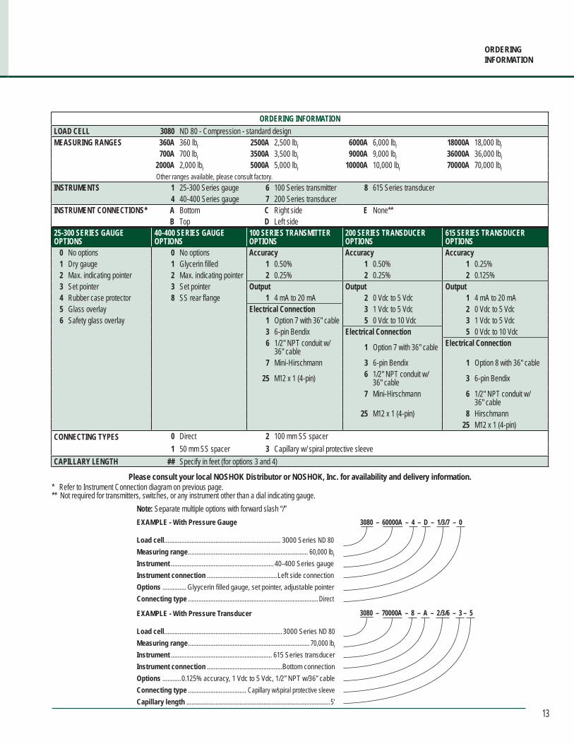
ORDERINGINFORMATION
ORDERING INFORMATIONLOAD CELL 3080 ND 80 - Compression - standard design MEASURING RANGES 360A 360 lbf 2500A 2,500 lbf 6000A 6,000 lbf 18000A 18,000 lbf
700A 700 lbf 3500A 3,500 lbf 9000A 9,000 lbf 36000A 36,000 lbf2000A 2,000 lbf 5000A 5,000 lbf 10000A 10,000 lbf 70000A 70,000 lbfOther ranges available, please consult factory.
INSTRUMENTS 1 25-300 Series gauge 6 100 Series transmitter 8 615 Series transducer4 40-400 Series gauge 7 200 Series transducer
INSTRUMENT CONNECTIONS* A Bottom C Right side E None**B Top D Left side
25-300 SERIES GAUGE OPTIONS
40-400 SERIES GAUGE OPTIONS
100 SERIES TRANSMITTEROPTIONS
200 SERIES TRANSDUCEROPTIONS
615 SERIES TRANSDUCEROPTIONS
0 No options 0 No options Accuracy Accuracy Accuracy1 Dry gauge 1 Glycerin filled 1 0.50% 1 0.50% 1 0.25%2 Max. indicating pointer 2 Max. indicating pointer 2 0.25% 2 0.25% 2 0.125%3 Set pointer 3 Set pointer Output Output Output4 Rubber case protector 8 SS rear flange 1 4 mA to 20 mA 2 0 Vdc to 5 Vdc 1 4 mA to 20 mA5 Glass overlay Electrical Connection 3 1 Vdc to 5 Vdc 2 0 Vdc to 5 Vdc6 Safety glass overlay 1 Option 7 with 36" cable 5 0 Vdc to 10 Vdc 3 1 Vdc to 5 Vdc
3 6-pin Bendix Electrical Connection 5 0 Vdc to 10 Vdc6 1/2" NPT conduit w/
36" cable 1 Option 7 with 36" cable Electrical Connection
7 Mini-Hirschmann 3 6-pin Bendix 1 Option 8 with 36" cable
25 M12 x 1 (4-pin) 6 1/2" NPT conduit w/ 36" cable 3 6-pin Bendix
7 Mini-Hirschmann 6 1/2" NPT conduit w/ 36" cable
25 M12 x 1 (4-pin) 8 Hirschmann 25 M12 x 1 (4-pin)
CONNECTING TYPES 0 Direct 2 100 mm SS spacer1 50 mm SS spacer 3 Capillary w/ spiral protective sleeve
CAPILLARY LENGTH ## Specify in feet (for options 3 and 4)
Please consult your local NOSHOK Distributor or NOSHOK, Inc. for availability and delivery information.
Note: Separate multiple options with forward slash “/” EXAMPLE - With Pressure Gauge
Load cell .................................................................... 3000 Series ND 80Measuring range ...................................................................... 60,000 lbf
Instrument ............................................................ 40-400 Series gaugeInstrument connection .........................................Left side connectionOptions .............. Glyycerin filled gauge, set pointer, adjustable pointerConnecting type ............................................................................Direct
3080 – 60000A – 4 – D – 1/3/7 – 0
EXAMPLE - With Pressure Transducer
Load cell .....................................................................3000 Series ND 80Measuring range ....................................................................... 70,000 lbf
Instrument ........................................................... 615 Series transducerInstrument connection ............................................Bottom connectionOptions ...........0.125% accuracy, 1 Vdc to 5 Vdc, 1/2” NPT w/36” cableConnecting type .................................. Capillary w/spiral protective sleeveCapillary length ....................................................................................5′
3080 – 70000A – 8 – A – 2/3/6 – 3 – 5
* Refer to Instrument Connection diagram on previous page.** Not required for transmitters, switches, or any instrument other than a dial indicating gauge.
14
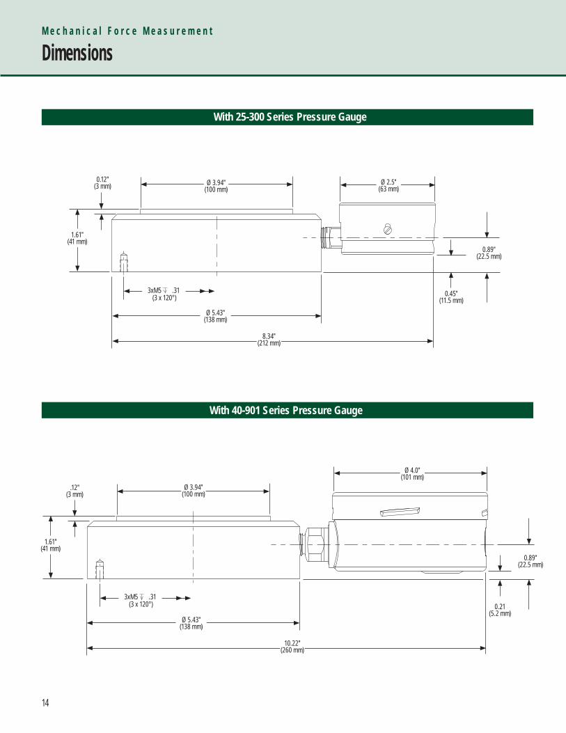
M e c h a n i c a l F o r c e M e a s u r e m e n t
Dimensions
With 25-300 Series Pressure Gauge
Ø 3.94″(100 mm)
0.12″(3 mm)
1.61″(41 mm)
Ø 5.43″(138 mm)
8.34″(212 mm)
Ø 2.5″(63 mm)
With 40-901 Series Pressure Gauge
0.45″(11.5 mm)
0.89″(22.5 mm)
Ø 3.94″(100 mm)
.12″(3 mm)
1.61″(41 mm)
Ø 5.43″(138 mm)
10.22″(260 mm)
Ø 4.0″(101 mm)
0.21(5.2 mm)
0.89″(22.5 mm)
3xM5 .31 (3 x 120°)
3xM5 .31 (3 x 120°)
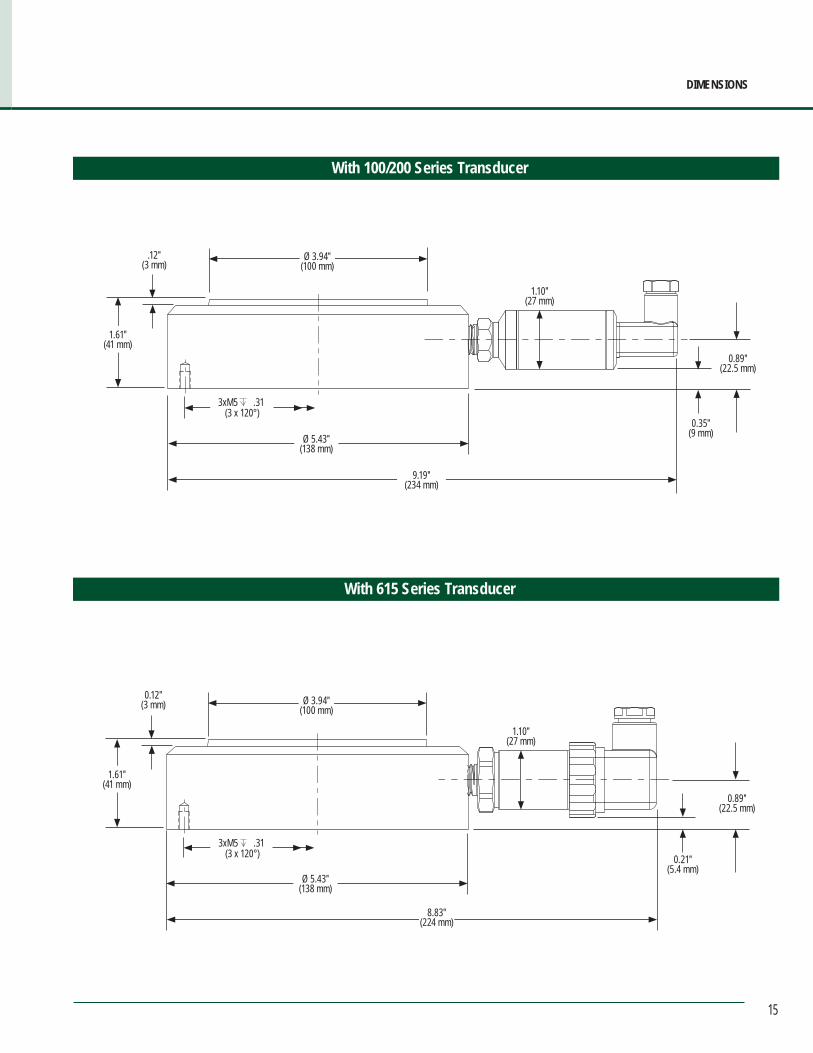
15
DIMENSIONS
With 100/200 Series Transducer
With 615 Series Transducer
Ø 3.94″(100 mm)
0.12″(3 mm)
1.61″(41 mm)
Ø 5.43″(138 mm)
8.83″(224 mm)
0.21″(5.4 mm)
0.89″(22.5 mm)
1.10″(27 mm)
3xM5 .31 (3 x 120°)
Ø 3.94″(100 mm)
.12″(3 mm)
1.61″(41 mm)
Ø 5.43″(138 mm)
9.19″(234 mm)
0.35″(9 mm)
0.89″(22.5 mm)
1.10″(27 mm)
3xM5 .31 (3 x 120°)
16
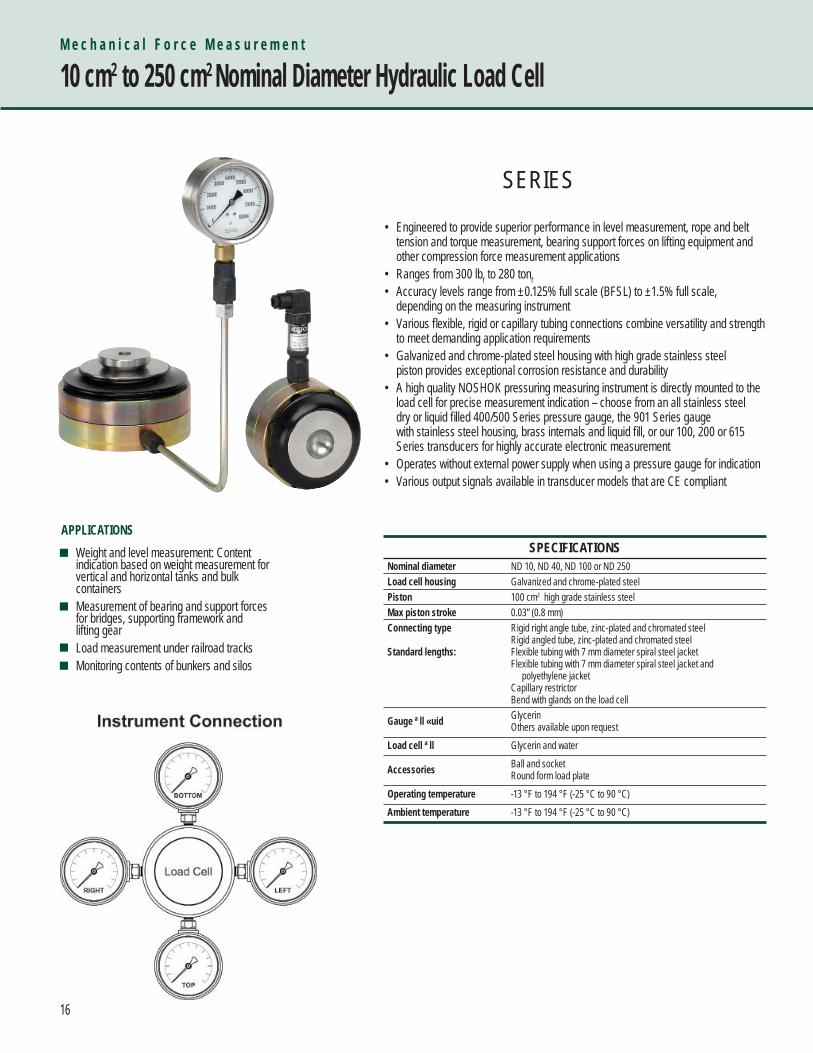
• Engineered to provide superior performance in level measurement, rope and belt tension and torque measurement, bearing support forces on lifting equipment and other compression force measurement applications• Ranges from 300 lbf to 280 tonf• Accuracy levels range from ±0.125% full scale (BFSL) to ±1.5% full scale, depending on the measuring instrument• Various fl exible, rigid or capillary tubing connections combine versatility and strength to meet demanding application requirements • Galvanized and chrome-plated steel housing with high grade stainless steel piston provides exceptional corrosion resistance and durability• A high quality NOSHOK pressuring measuring instrument is directly mounted to the load cell for precise measurement indication – choose from an all stainless steel dry or liquid fi lled 400/500 Series pressure gauge, the 901 Series gauge with stainless steel housing, brass internals and liquid fi ll, or our 100, 200 or 615 Series transducers for highly accurate electronic measurement• Operates without external power supply when using a pressure gauge for indication• Various output signals available in transducer models that are CE compliant
M e c h a n i c a l F o r c e M e a s u r e m e n t
10 cm2 to 250 cm2 Nominal Diameter Hydraulic Load Cell
SPECIFICATIONSNominal diameter ND 10, ND 40, ND 100 or ND 250Load cell housing Galvanized and chrome-plated steel Piston 100 cm2 high grade stainless steel Max piston stroke 0.03” (0.8 mm)Connecting type
Standard lengths:
Rigid right angle tube, zinc-plated and chromated steelRigid angled tube, zinc-plated and chromated steelFlexible tubing with 7 mm diameter spiral steel jacketFlexible tubing with 7 mm diameter spiral steel jacket and polyethylene jacketCapillary restrictorBend with glands on the load cell
Gauge ll uid GlycerinOthers available upon request
Load cell ll Glycerin and water
Accessories Ball and socketRound form load plate
Operating temperature -13 °F to 194 °F (-25 °C to 90 °C) Ambient temperature -13 °F to 194 °F (-25 °C to 90 °C)
Weight and level measurement: Content indication based on weight measurement for vertical and horizontal tanks and bulk containers Measurement of bearing and support forces for bridges, supporting framework and lifting gear Load measurement under railroad tracks Monitoring contents of bunkers and silos
APPLICATIONS
SERIES
17
ORDERINGINFORMATION
ORDERING INFORMATIONLOAD CELLS 4010 ND 10 - Compression - standard design 4100 ND 100 - Compression - standard design
4040 ND 40 - Compression - standard design 4250 ND 250 - Compression - standard design MEASURING RANGES 4010 - ND 10 4040 - ND 40 4100 - ND 100 4250 - ND 250
300A 300 lbf 5000A 5,000 lbf 90000A 90,000 lbf 115F 115 tonf600A 600 lbf 6000A 6,000 lbf 57F 57 tonf 140F 140 tonf900A 900 lbf 9000A 9,000 lbf 75F 75 tonf 200F 200 tonf
1200A 1,200 lbf 18000A 18,000 lbf 110F 110 tonf 280F 280 tonf1500A 1,500 lbf 30000A 30,000 lbf3000A 3,000 lbf 45000A 45,000 lbf4500A 4,500 lbf 60000A 60,000 lbf Other ranges available, please consult factory.
INSTRUMENTS 3 40-400 Series gauge 6 100 Series transmitter 8 615 Series transducer5 60-400 Series gauge 7 200 Series transducer
INSTRUMENT CONNECTIONS* A Bottom C Right side E None**B Top D Left side
40-400 SERIES GAUGE OPTIONS
60-400 SERIES GAUGE OPTIONS
100 SERIES TRANSMITTEROPTIONS
200 SERIES TRANSDUCEROPTIONS
615 SERIES TRANSDUCEROPTIONS
0 No options 0 No options Accuracy Accuracy Accuracy1 Glycerin filled 1 Glycerin filled 1 0.50% 1 0.50% 1 0.25%2 Max. indicating pointer 2 Max. indicating pointer 2 0.25% 2 0.25% 2 0.125%3 Set pointer 3 Set pointer Output Output Output4 Rubber case protector 8 SS rear flange 1 4 mA to 20 mA 2 0 Vdc to 5 Vdc 1 4 mA to 20 mA6 Safety glass overlay Electrical Connection 3 1 Vdc to 5 Vdc 2 0 Vdc to 5 Vdc7 Adjustable pointer 1 Option 7 with 36" cable 5 0 Vdc to 10 Vdc 3 1 Vdc to 5 Vdc8 SS rear flange 3 6-pin Bendix Electrical Connection 5 0 Vdc to 10 Vdc
6 1/2" NPT conduit w/ 36" cable 1 Option 7 with 36" cable Electrical Connection
7 Mini-Hirschmann 3 6-pin Bendix 1 Option 8 with 36" cable
25 M12 x 1 (4-pin) 6 1/2" NPT conduit w/ 36" cable 3 6-pin Bendix
7 Mini-Hirschmann 6 1/2" NPT conduit w/ 36" cable
25 M12 x 1 (4-pin) 8 Hirschmann 25 M12 x 1 (4-pin)
CONNECTING TYPES 0 Direct 2 100 mm SS spacer1 50 mm SS spacer 3 Capillary w/ spiral protective sleeve
CAPILLARY LENGTH ## Specify in feet (for options 3 and 4)
Please consult your local NOSHOK Distributor or NOSHOK, Inc. for availability and delivery information.
Note: Separate multiple options with forward slash “/”
EXAMPLE - With Pressure Gauge
Load cell ......................................4000 Series ND 100Measuring range .......................................... 110 tonf
Instrument .............................60-400 Series gaugeInstrument connection ............Bottom connectionOptions ......................... Set pointer, SS rear flangeConnecting type ...Capillary w/spiral protective sleeveCapillary length .................................................. 10′
4100 – 110F – 5 – A – 3/8 – 3 – 10 EXAMPLE - With Pressure Transducer
Load cell ..................................... 4000 Series ND 100Measuring range ......................................... 90,000 lbf
Instrument ..............................615 Series transducerInstrument connection ..............Bottom connectionOptions .................0.125% accuracy, 1 Vdc to 5 Vdc, .................................. 1/2” NPT conduit with 36” cableConnecting type .....Capillary w/spiral protective sleeveCapillary length ...................................................... 5′
4100 – 90000A – 8 – A – 2/3/6 – 3 – 5
* Refer to Instrument Connection diagram on previous page.** Not required for transmitters, switches, or any instrument other than a dial indicating gauge.

18
M e c h a n i c a l F o r c e M e a s u r e m e n t
Dimensions
10 mm Load Cell
40 mm Load Cell
Ø 1.77″ (45 mm)
Ø 1.38″(35 mm)
0.67″(17 mm)
2.24″(57 mm)
* Ball and ball socket for diameters 10 mm and 40 mm** Round form load plate for diameters 100 mm and 250 mm
* Ball socket* Ball
Piston
All fittings shrink wrapped.
0.63″(16 mm)
0.39″ (10 mm)
0.10″ (2.5 mm)
Ø 3.46″ (88 mm)
3.90″ (99 mm)
2.20″ (56 mm)
3.11″ (79 mm)
0.63″ (16 mm)
.71″ (18 mm)
Position of the boring in the flange Position of the threaded boring in the base of the casing
Ø 3.54″ (90 mm)
Ø 2.68″(68 mm)
0.75″(19 mm)
3.23″(82 mm)
* Ball and ball socket for diameters 10 mm and 40 mm** Round form load plate for diameters 100 mm and 250 mm
* Ball socket* Ball
Piston
All fittings shrink wrapped.
0.67″(17 mm)
0.79″ (20 mm)
0.16″ (4 mm)
Ø 5.43″ (138 mm)
4.94″ (125.5 mm)
2.48″ (63 mm)
3.37″ (85.5 mm)
0.71″ (18 mm)
0.79″ (20 mm)
Position of the boring in the flange Position of the threaded boring in the base of the casing
60°120°
4 X Ø 0.55″ (14 mm)
4.13″ (105 mm)
3.15″ (80 mm)
3.15″ (80 mm)
4.13″ (105 mm)
Ø 2.76″ (70 mm)
4 X M8EQ SPACED
45°5.91″ (150 mm)
4.72″ (120 mm)
4.72″ (120 mm)
5.91″ (150 mm)
Ø 4.72″ (120 mm)
8 X M10EQ SPACED
90°
4 X Ø 0.55″ (14 mm)
19
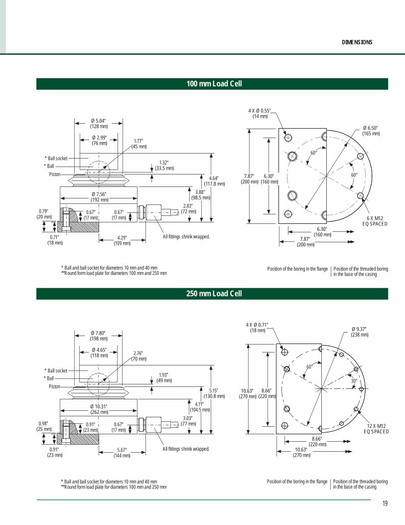
DIMENSIONS
100 mm Load Cell
250 mm Load Cell
Position of the boring in the flange Position of the threaded boring in the base of the casing
Ø 5.04″ (128 mm)
Ø 2.99″(76 mm)
0.67″(17 mm)
4.29″(109 mm)
* Ball and ball socket for diameters 10 mm and 40 mm** Round form load plate for diameters 100 mm and 250 mm
* Ball socket* Ball
Piston
All fittings shrink wrapped.
0.67″(17 mm)
1.77″ (45 mm)
1.32″ (33.5 mm)
Ø 7.56″ (192 mm)
4.64″ (117.8 mm)
3.88″ (98.5 mm)
0.71″ (18 mm)
0.79″ (20 mm)
2.83″ (72 mm)
Position of the boring in the flange Position of the threaded boring in the base of the casing
Ø 7.80″ (198 mm)
Ø 4.65″(118 mm)
0.91″(23 mm)
5.67″(144 mm)
* Ball and ball socket for diameters 10 mm and 40 mm** Round form load plate for diameters 100 mm and 250 mm
* Ball socket* Ball
Piston
All fittings shrink wrapped.
0.67″(17 mm)
2.76″ (70 mm)
1.93″ (49 mm)
Ø 10.31″ (262 mm)
4.11″ (104.5 mm)
0.91″ (23 mm)
0.98″ (25 mm)
3.03″ (77 mm)
5.15″ (130.8 mm)
60°7.87″ (200 mm)
6.30″ (160 mm)
7.87″ (200 mm)
Ø 6.50″ (165 mm)
6 X M12EQ SPACED
60°
4 X Ø 0.55″ (14 mm)
30°
10.63″ (270 mm)
8.66″ (220 mm)
8.66″ (220 mm)
10.63″ (270 mm)
Ø 9.37″ (238 mm)
12 X M12EQ SPACED
60°
4 X Ø 0.71″ (18 mm)
6.30″ (160 mm)

20
• Designed in a distinctive ring shape to provide superior performance in compression or tension force measurement applications• Ranges from 900 lbf to 315 tonf• Accuracy levels range from ±0.125% full scale (BFSL) to ±1.5% full scale, depending on the measuring instrument• Various fl exible, rigid or capillary tubing connections combine versatility and strength to meet demanding application requirements • High grade stainless steel housing and piston provide exceptional corrosion resistance and durability• A high quality NOSHOK pressuring measuring instrument is directly mounted to the load cell for precise measurement indication – choose from an all stainless steel dry or liquid fi lled 400/500 Series pressure gauge, the 901 Series gauge with stainless steel housing, brass internals and liquid fi ll, or our 100, 200 or 615 Series transducers for highly accurate electronic measurement• Operates without external power supply when using a pressure gauge for indication• Various output signals available in transducer models that are CE compliant
M e c h a n i c a l F o r c e M e a s u r e m e n t
40 cm2 to 410 cm2 Nominal Diameter Hydraulic Load Cell
SPECIFICATIONSNominal diameter ND 40, ND 60, ND 90, ND 160, ND 240 or ND 410Load cell housing 160 cm2 high grade stainless steel Piston High grade stainless steel Max piston stroke 0.03” (0.8 mm)Connecting type
Standard lengths:
Rigid right angle tube, zinc-plated and chromated steelRigid angled tube, zinc-plated and chromated steelFlexible tubing with 7 mm diameter spiral steel jacketFlexible tubing with 7 mm diameter spiral steel jacket and polyethylene jacketCapillary restrictorBend with glands on the load cell
Gauge ll uid GlycerinOthers available upon request
Load cell ll Glycerin and water
Accessories Ball and socketRound form load plate
Operating temperature -13 °F to 194 °F (-25 °C to 90 °C) Ambient temperature -13 °F to 194 °F (-25 °C to 90 °C)
Injection molding machine screws, tailstock spindles, propeller shafts, rope and torque measurement Material handling and hoisting technology; measurement of tension force in cables and ropes on coal excavators and supervision of steel rope tension on cable railways Adjustment and monitoring of compression forces at rolling frames; mounted underneath the screw-down gear of the roller bearing Adjustment and monitoring at turning, milling and deep-hole boring machines; forward feed force measurement and overload detection (i.e. at tool breakage) Rock thrust measurement in fore poles in mines and tunnel construction
APPLICATIONS
SERIES
21
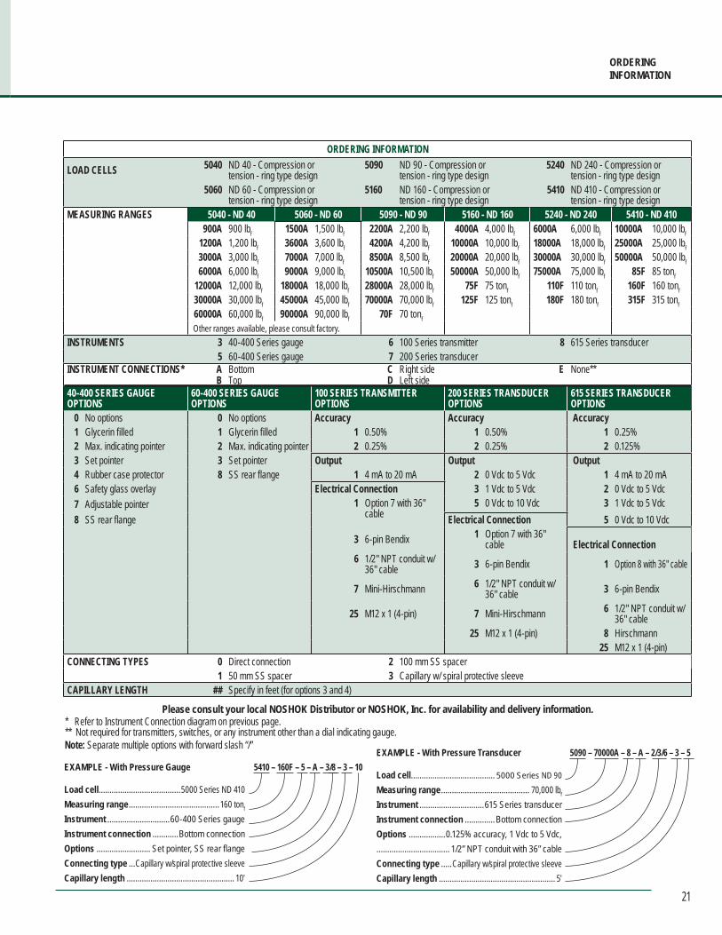
ORDERINGINFORMATION
ORDERING INFORMATION
LOAD CELLS 5040 ND 40 - Compression or tension - ring type design
5090 ND 90 - Compression or tension - ring type design
5240 ND 240 - Compression or tension - ring type design
5060 ND 60 - Compression or tension - ring type design
5160 ND 160 - Compression or tension - ring type design
5410 ND 410 - Compression or tension - ring type design
MEASURING RANGES 5040 - ND 40 5060 - ND 60 5090 - ND 90 5160 - ND 160 5240 - ND 240 5410 - ND 410900A 900 lbf 1500A 1,500 lbf 2200A 2,200 lbf 4000A 4,000 lbf 6000A 6,000 lbf 10000A 10,000 lbf
1200A 1,200 lbf 3600A 3,600 lbf 4200A 4,200 lbf 10000A 10,000 lbf 18000A 18,000 lbf 25000A 25,000 lbf3000A 3,000 lbf 7000A 7,000 lbf 8500A 8,500 lbf 20000A 20,000 lbf 30000A 30,000 lbf 50000A 50,000 lbf6000A 6,000 lbf 9000A 9,000 lbf 10500A 10,500 lbf 50000A 50,000 lbf 75000A 75,000 lbf 85F 85 tonf
12000A 12,000 lbf 18000A 18,000 lbf 28000A 28,000 lbf 75F 75 tonf 110F 110 tonf 160F 160 tonf30000A 30,000 lbf 45000A 45,000 lbf 70000A 70,000 lbf 125F 125 tonf 180F 180 tonf 315F 315 tonf60000A 60,000 lbf 90000A 90,000 lbf 70F 70 tonfOther ranges available, please consult factory.
INSTRUMENTS 3 40-400 Series gauge 6 100 Series transmitter 8 615 Series transducer5 60-400 Series gauge 7 200 Series transducer
INSTRUMENT CONNECTIONS* A Bottom C Right side E None**B Top D Left side
40-400 SERIES GAUGE OPTIONS
60-400 SERIES GAUGE OPTIONS
100 SERIES TRANSMITTEROPTIONS
200 SERIES TRANSDUCEROPTIONS
615 SERIES TRANSDUCEROPTIONS
0 No options 0 No options Accuracy Accuracy Accuracy1 Glycerin filled 1 Glycerin filled 1 0.50% 1 0.50% 1 0.25%2 Max. indicating pointer 2 Max. indicating pointer 2 0.25% 2 0.25% 2 0.125%3 Set pointer 3 Set pointer Output Output Output4 Rubber case protector 8 SS rear flange 1 4 mA to 20 mA 2 0 Vdc to 5 Vdc 1 4 mA to 20 mA6 Safety glass overlay Electrical Connection 3 1 Vdc to 5 Vdc 2 0 Vdc to 5 Vdc7 Adjustable pointer 1 Option 7 with 36"
cable5 0 Vdc to 10 Vdc 3 1 Vdc to 5 Vdc
8 SS rear flange Electrical Connection 5 0 Vdc to 10 Vdc
3 6-pin Bendix 1 Option 7 with 36" cable Electrical Connection
6 1/2" NPT conduit w/ 36" cable 3 6-pin Bendix 1 Option 8 with 36" cable
7 Mini-Hirschmann 6 1/2" NPT conduit w/ 36" cable 3 6-pin Bendix
25 M12 x 1 (4-pin) 7 Mini-Hirschmann 6 1/2" NPT conduit w/ 36" cable
25 M12 x 1 (4-pin) 8 Hirschmann 25 M12 x 1 (4-pin)
CONNECTING TYPES 0 Direct connection 2 100 mm SS spacer1 50 mm SS spacer 3 Capillary w/ spiral protective sleeve
CAPILLARY LENGTH ## Specify in feet (for options 3 and 4)
Please consult your local NOSHOK Distributor or NOSHOK, Inc. for availability and delivery information.
Note: Separate multiple options with forward slash “/”
EXAMPLE - With Pressure Gauge
Load cell ......................................5000 Series ND 410Measuring range ..........................................160 tonf
Instrument .............................60-400 Series gaugeInstrument connection ............Bottom connectionOptions ......................... Set pointer, SS rear flangeConnecting type ...Capillary w/spiral protective sleeveCapillary length .................................................. 10′
5410 – 160F – 5 – A – 3/8 – 3 – 10 EXAMPLE - With Pressure Transducer
Load cell ....................................... 5000 Series ND 90Measuring range ......................................... 70,000 lbf
Instrument ..............................615 Series transducerInstrument connection ..............Bottom connectionOptions .................0.125% accuracy, 1 Vdc to 5 Vdc, .................................. 1/2” NPT conduit with 36” cableConnecting type .....Capillary w/spiral protective sleeveCapillary length ...................................................... 5′
5090 – 70000A – 8 – A – 2/3/6 – 3 – 5
* Refer to Instrument Connection diagram on previous page.** Not required for transmitters, switches, or any instrument other than a dial indicating gauge.

22
M e c h a n i c a l F o r c e M e a s u r e m e n t
Dimensions
ND 40 Load Cell
Ø 3.27″ (83 mm)
Ø 1.50″ (38 mm)
Ø 0.98″ (25 mm)
2.28″ (58 mm)
0.12″ (3 mm)
4x M 8
Ø 3.94″ (100 mm)
0.89″ (22.5 mm)Ø 2.76″
(70 mm)
Pressure instrument connection
ND 60 Load Cell
ND 90 Load Cell ND 160 Load Cell
Ø 3.94″ (100 mm)
Ø 2.20″ (56 mm)
Ø 1.57″ (40 mm)
2.44″ (62 mm)
0.20″ (5 mm)
4x M 8
Ø 4.72″ (120 mm)
0.89″ ( 22.5 mm)Ø 3.54″
(90 mm)
Pressure gauge connection
Ø 5.12″ (130 mm)
Ø 3.15″ (80 mm)
Ø 2.36″ (60 mm)
2.68″ (68 mm)
0.20″ ( 5 mm)
4x M 10
Ø 6.69″ (170 mm)
0.89″ ( 22.5 mm)
Ø 4.72″ (120 mm)
Ø 7.09″ (180 mm)
Ø 4.72″ (120 mm)
Ø 3.94″ (100 mm)
2.76″ (70 mm)
0.20″ (5 mm)
4x M 10
Ø 8.27″ (210 mm)
0.89″ (22.5 mm)
Ø 6.69″ (170 mm)
Pressure gauge connection
Pressure instrument connection
23
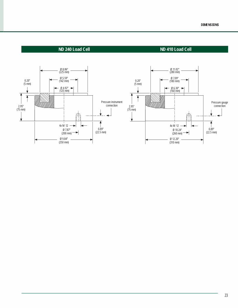
ND 240 Load Cell ND 410 Load Cell
Ø 8.86″ (225 mm)
Ø 5.59″ (142 mm)
Ø 4.92″ (125 mm)
2.95″ (75 mm)
0.20″ (5 mm)
4x M 12
Ø 9.84″ (250 mm)
0.89″ (22.5 mm)
Ø 7.87″ (200 mm)
Ø 11.02″ (280 mm)
Ø 7.09″ (180 mm)
Ø 6.30″ (160 mm)
2.95″ (75 mm)
0.20″ (5 mm)
4x M 12
Ø 12.20″ (310 mm)
0.89″ (22.5 mm)
Ø 10.24″ (260 mm)
Pressure gauge connection
DIMENSIONS
Pressure instrument connection
24
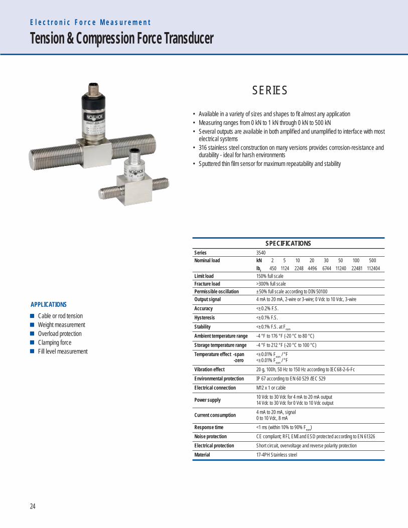
• Available in a variety of sizes and shapes to fi t almost any application• Measuring ranges from 0 kN to 1 kN through 0 kN to 500 kN• Several outputs are available in both amplifi ed and unamplifi ed to interface with most electrical systems• 316 stainless steel construction on many versions provides corrosion-resistance and durability - ideal for harsh environments• Sputtered thin fi lm sensor for maximum repeatability and stability
E l e c t r o n i c F o r c e M e a s u r e m e n t
Tension & Compression Force Transducer
SPECIFICATIONSSeries 3540Nominal load kN 2 5 10 20 30 50 100 500
lbf 450 1124 2248 4496 6744 11240 22481 112404Limit load 150% full scaleFracture load >300% full scalePermissible oscillation ±50% full scale according to DIN 50100Output signal 4 mA to 20 mA, 2-wire or 3-wire; 0 Vdc to 10 Vdc, 3-wireAccuracy <±0.2% F.S.Hysteresis <±0.1% F.S.Stability <±0.1% F.S. at Fnom
Ambient temperature range -4 °F to 176 °F (-20 °C to 80 °C)Storage temperature range -4 °F to 212 °F (-20 °C to 100 °C)Temperature effect -span -zero
<±0.01% Fnom / °F<±0.01% Fnom / °F
Vibration effect 20 g, 100h, 50 Hz to 150 Hz according to IEC68-2-6-FcEnvironmental protection IP 67 according to EN 60 529 /IEC 529Electrical connection M12 x 1 or cable
Power supply 10 Vdc to 30 Vdc for 4 mA to 20 mA output14 Vdc to 30 Vdc for 0 Vdc to 10 Vdc output
Current consumption 4 mA to 20 mA, signal0 to 10 Vdc, 8 mA
Response time <1 ms (within 10% to 90% Fnom)Noise protection CE compliant; RFI, EMI and ESD protected according to EN 61326Electrical protection Short circuit, overvoltage and reverse polarity protectionMaterial 17-4PH Stainless steel
Cable or rod tension Weight measurement Overload protection Clamping force Fill level measurement
APPLICATIONS
SERIES
25
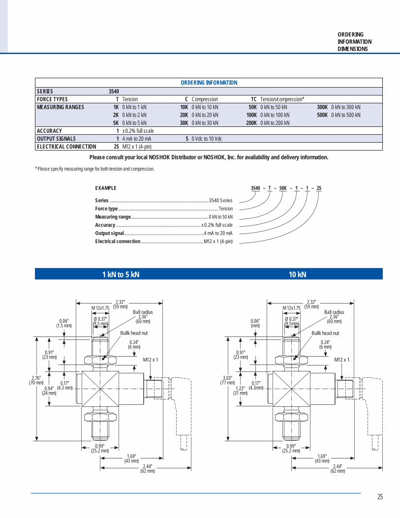
ORDERINGINFORMATIONDIMENSIONS
ORDERING INFORMATIONSERIES 3540FORCE TYPES T Tension C Compression TC Tension/compression*MEASURING RANGES 1K 0 kN to 1 kN 10K 0 kN to 10 kN 50K 0 kN to 50 kN 300K 0 kN to 300 kN
2K 0 kN to 2 kN 20K 0 kN to 20 kN 100K 0 kN to 100 kN 500K 0 kN to 500 kN5K 0 kN to 5 kN 30K 0 kN to 30 kN 200K 0 kN to 200 kN
ACCURACY 1 ±0.2% full scaleOUTPUT SIGNALS 1 4 mA to 20 mA 5 0 Vdc to 10 VdcELECTRICAL CONNECTION 25 M12 x 1 (4-pin)
Please consult your local NOSHOK Distributor or NOSHOK, Inc. for availability and delivery information.
* Please specify measuring range for both tension and compression.
1 kN to 5 kN
EXAMPLE
Series ...................................................................................3540 SeriesForce type .................................................................................... TensionMeasuring range .................................................................0 kN to 50 kNAccuracy ....................................................................... ±0.2% full scaleOutput signal ...................................................................4 mA to 20 mAElectrical connection .....................................................M12 x 1 (4-pin)
3540 – T – 50K – 1 – 1 – 25
10 kN
0.94″ (24 mm)
0.91″ (23 mm)
0.06″ (1.5 mm)
0.17″ (4.3 mm)
0.99″ (25.2 mm)
2.44″ (62 mm)
1.69″ (43 mm)
0.24″ (6 mm)
M 12x1.75
Ø 0.37″ (9.5 mm)
2.32″ (59 mm)
M12 x 1
Ball radius2.36″
(60 mm)
Bullk head nut
2.76″ (70 mm)
1.22″ (31 mm)
0.91″ (23 mm)
0.06″ (mm)
0.17″ (4.3mm)
0.99″ (25.2 mm)
0.24″ (6 mm)
M 12x1.75
Ø 0.37″ (9.5mm)
2.32″ (59 mm)
M12 x 1
Ball radius2.36″
(60 mm)
Bullk head nut
3.03″ (77 mm)
2.44″ (62 mm)
1.69″ (43 mm)
26
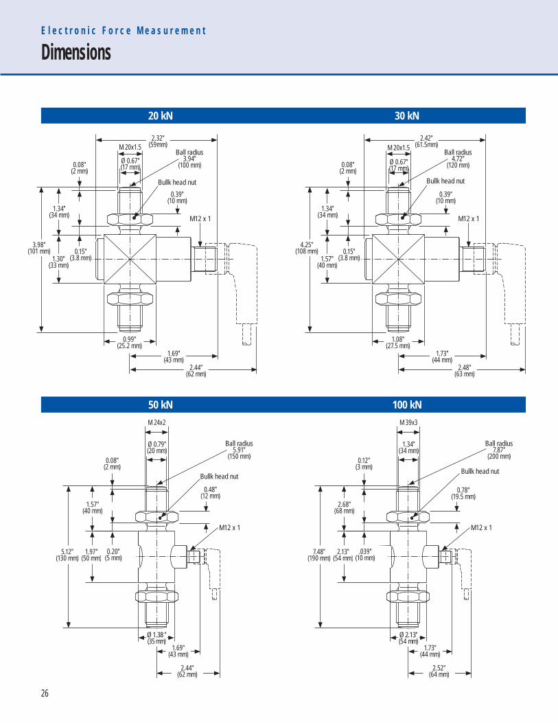
E l e c t r o n i c F o r c e M e a s u r e m e n t
Dimensions
M12 x 1
Ball radius7.87″
(200 mm)
Bullk head nut
M 39x3
1.34″ (34 mm)
2.52″ (64 mm)
1.73″ (44 mm)
7.48″ (190 mm)
2.13″ (54 mm)
2.68″ (68 mm)
0.12″ (3 mm)
.039″ (10 mm)
Ø 2.13″(54 mm)
M12 x 1
Ball radius5.91″
(150 mm)
Bullk head nut
Ø 1.38 ″(35 mm)
M 24x2
Ø 0.79″ (20 mm)
2.44″ (62 mm)
1.69″ (43 mm)
5.12″ (130 mm)
1.97″ (50 mm)
1.57″ (40 mm)
0.08″ (2 mm)
0.20″ (5 mm)
20 kN 30 kN
50 kN 100 kN
1.30″ (33 mm)
1.34″ (34 mm)
0.08″ (2 mm)
0.15″ (3.8 mm)
0.99″ (25.2 mm)
2.44″ (62 mm)
1.69″ (43 mm)
0.39″ (10 mm)
M 20x1.5
Ø 0.67″ (17 mm)
2.32″ (59mm)
M12 x 1
Ball radius3.94″
(100 mm)
Bullk head nut
3.98″ (101 mm)
1.57″ (40 mm)
1.34″ (34 mm)
0.08″ (2 mm)
0.15″ (3.8 mm)
1.08″ (27.5 mm)
2.48″ (63 mm)
1.73″ (44 mm)
0.39″ (10 mm)
M 20x1.5
Ø 0.67″ (17 mm)
2.42″ (61.5mm)
M12 x 1
Ball radius4.72″
(120 mm)
Bullk head nut
4.25″ (108 mm)
0.48″ (12 mm)
0.78″ (19.5 mm)
27
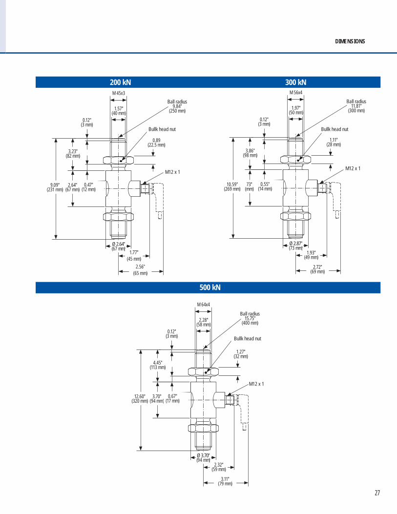
DIMENSIONS
500 kN
M12 x 1
Ball radius11.81″
(300 mm)
Bullk head nut
Ø 2.87″(73 mm)
M 56x4
1.97″ (50 mm)
2.72″ (69 mm)
1.93″ (49 mm)
10.59″ (269 mm)
73″ (mm)
3.86″ (98 mm)
0.12″ (3 mm)
0.55″ (14 mm)
M12 x 1
Ball radius9.84″
(250 mm)
Bullk head nut
Ø 2.64″(67 mm)
M 45x3
1.57″ (40 mm)
2.56″ (65 mm)
1.77″ (45 mm)
9.09″ (231 mm)
2.64″ (67 mm)
3.23″ (82 mm)
0.12″ (3 mm)
0.47″ (12 mm)
M12 x 1
Ball radius15.75″
(400 mm)
Bullk head nut
Ø 3.70″(94 mm)
M 64x4
2.28″ (58 mm)
3.11″ (79 mm)
2.32″ (59 mm)
12.60″ (320 mm)
3.70″ (94 mm)
4.45″ (113 mm)
0.12″ (3 mm)
0.67″ (17 mm)
200 kN 300 kN
0.89 (22.5 mm)
1.11″ (28 mm)
1.27″ (32 mm)

28
• Conventional design features internal threads which allow force to be easily introduced via suitable swivel heads• Calibrations in the tension or compression direction only are available at no extra charge• Features thin fi lm sensors and an integrated amplifi er• High shock and vibration resistance• Minimal temperature drift• For dynamic or static requirements• Overload protection is rated for 150% of the maximum nominal load• Protection Class IP 65 or IP 67• Accuracy up to 0.1% of full scale value
E l e c t r o n i c F o r c e M e a s u r e m e n t
S-Type Force Transducer
SPECIFICATIONSMeasuring ranges 0 to 20 N - 0 kN to 50 kNMaximum dynamic load ±70% Fnom according to DIN 50100Nominal de ection <0.15 mmAccuracy ±0.2% full scale (±0.1% full scale optional)Output signal 2 mV/VOperating temperature -30 °F to 85 °F (-34 °C to 29 °C)Temperature effect -span -zero
<±0.12% of full scale/10K (<±0.08% of full scale/10K optional)<±0.04% of full scale/10K (<±0.025% of full scale/10K optional)
Electrical protection Short circuit, overvoltage and reverse polarity protection
Plant engineering Production lines Measurement and monitoring facilities Special equipment and machinery construction Test benches and production lines
APPLICATIONS
SERIES
29
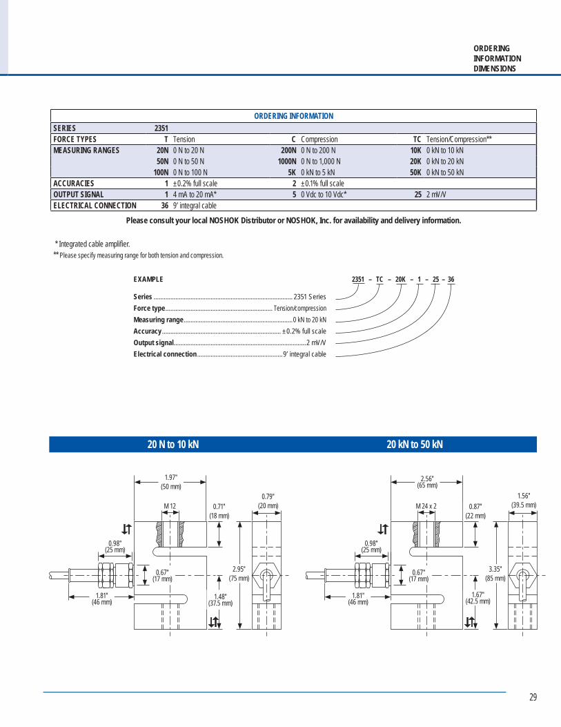
ORDERINGINFORMATIONDIMENSIONS
ORDERING INFORMATIONSERIES 2351FORCE TYPES T Tension C Compression TC Tension/Compression**MEASURING RANGES 20N 0 N to 20 N 200N 0 N to 200 N 10K 0 kN to 10 kN
50N 0 N to 50 N 1000N 0 N to 1,000 N 20K 0 kN to 20 kN100N 0 N to 100 N 5K 0 kN to 5 kN 50K 0 kN to 50 kN
ACCURACIES 1 ±0.2% full scale 2 ±0.1% full scaleOUTPUT SIGNAL 1 4 mA to 20 mA* 5 0 Vdc to 10 Vdc* 25 2 mV/VELECTRICAL CONNECTION 36 9’ integral cable
Please consult your local NOSHOK Distributor or NOSHOK, Inc. for availability and delivery information.
20 N to 10 kN
EXAMPLE
Series ................................................................................... 2351 SeriesForce type ................................................................ Tension/compressionMeasuring range .................................................................0 kN to 20 kNAccuracy ....................................................................... ±0.2% full scaleOutput signal ...............................................................................2 mV/VElectrical connection ...................................................9’ integral cable
2351 – TC – 20K – 1 – 25 – 36
20 kN to 50 kN
M 24 x 2
2.56″ (65 mm)
0.98″ (25 mm)
1.56″ (39.5 mm)
3.35″ (85 mm)
1.67″ (42.5 mm)
0.87″ (22 mm)
0.67″ (17 mm)
1.81″ (46 mm)
M 12
1.97″ (50 mm)
0.98″ (25 mm)
0.79″ (20 mm)
2.95″ (75 mm)
1.48″ (37.5 mm)
0.71″ (18 mm)
0.67″ (17 mm)
1.81″ (46 mm)
* Integrated cable amplifier.** Please specify measuring range for both tension and compression.
30
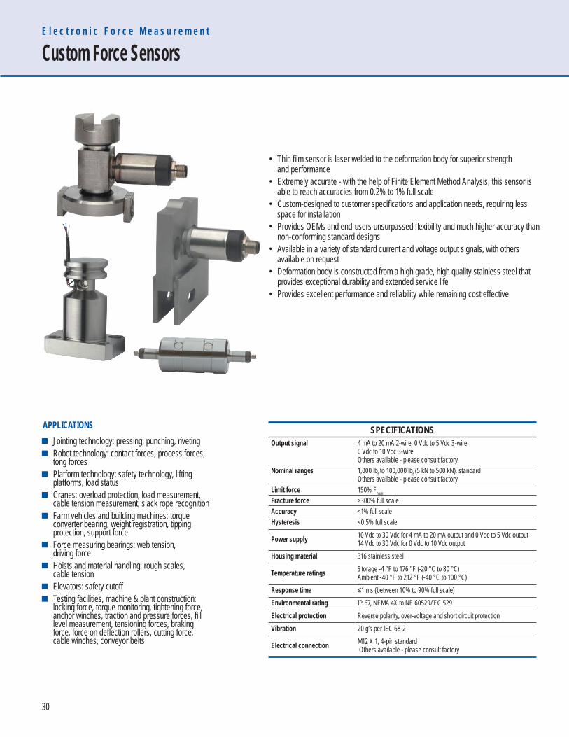
• Thin fi lm sensor is laser welded to the deformation body for superior strength and performance• Extremely accurate - with the help of Finite Element Method Analysis, this sensor is able to reach accuracies from 0.2% to 1% full scale• Custom-designed to customer specifi cations and application needs, requiring less space for installation• Provides OEMs and end-users unsurpassed fl exibility and much higher accuracy than non-conforming standard designs• Available in a variety of standard current and voltage output signals, with others available on request• Deformation body is constructed from a high grade, high quality stainless steel that provides exceptional durability and extended service life• Provides excellent performance and reliability while remaining cost effective
E l e c t r o n i c F o r c e M e a s u r e m e n t
Custom Force Sensors
SPECIFICATIONSOutput signal 4 mA to 20 mA 2-wire, 0 Vdc to 5 Vdc 3-wire
0 Vdc to 10 Vdc 3-wireOthers available - please consult factory
Nominal ranges 1,000 lbf to 100,000 lbf (5 kN to 500 kN), standardOthers available - please consult factory
Limit force 150% Fnom
Fracture force >300% full scaleAccuracy <1% full scaleHysteresis <0.5% full scale
Power supply 10 Vdc to 30 Vdc for 4 mA to 20 mA output and 0 Vdc to 5 Vdc output14 Vdc to 30 Vdc for 0 Vdc to 10 Vdc output
Housing material 316 stainless steel
Temperature ratings Storage -4 °F to 176 °F (-20 °C to 80 °C)Ambient -40 °F to 212 °F (-40 °C to 100 °C)
Response time ≤1 ms (between 10% to 90% full scale)Environmental rating IP 67, NEMA 4X to NE 60529/IEC 529Electrical protection Reverse polarity, over-voltage and short circuit protectionVibration 20 g’s per IEC 68-2
Electrical connection M12 X 1, 4-pin standard Others available - please consult factory
Jointing technology: pressing, punching, riveting Robot technology: contact forces, process forces, tong forces Platform technology: safety technology, lifting platforms, load status Cranes: overload protection, load measurement, cable tension measurement, slack rope recognition Farm vehicles and building machines: torque converter bearing, weight registration, tipping protection, support force Force measuring bearings: web tension, driving force Hoists and material handling: rough scales, cable tension Elevators: safety cutoff Testing facilities, machine & plant construction: locking force, torque monitoring, tightening force, anchor winches, traction and pressure forces, fill level measurement, tensioning forces, braking force, force on deflection rollers, cutting force, cable winches, conveyor belts
APPLICATIONS
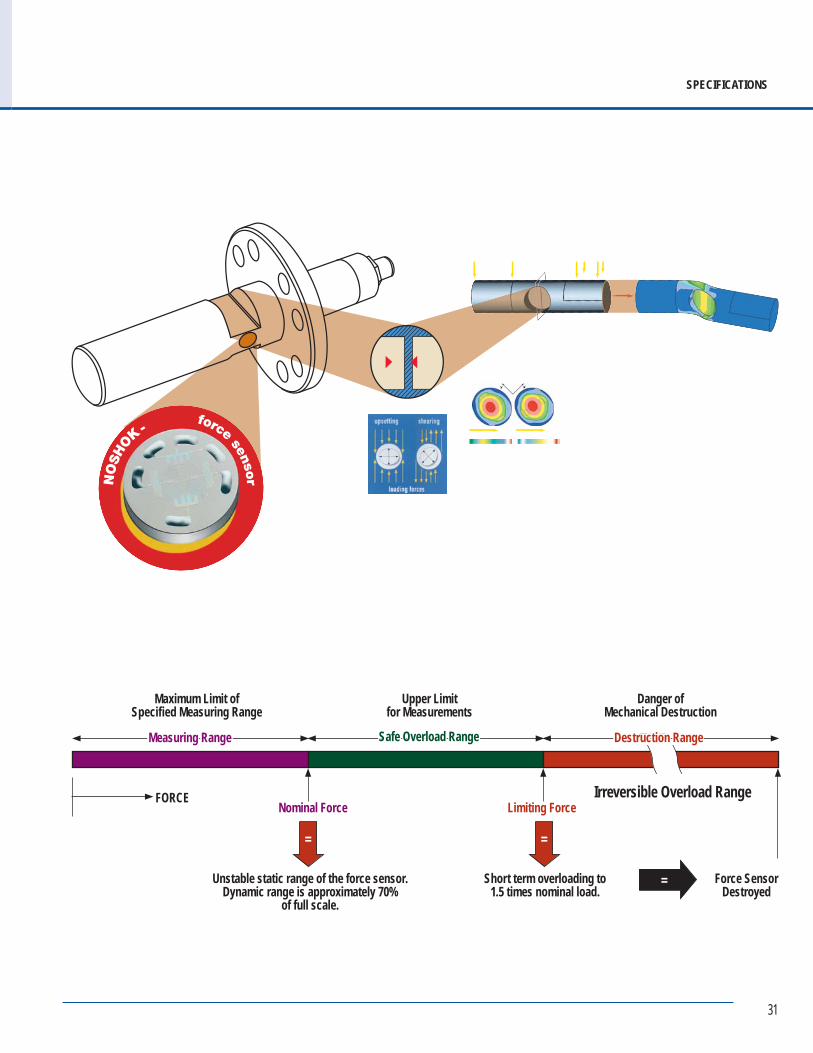
31
Measuring Range Safe Overload Range Destruction Range
Maximum Limit of Specified Measuring Range
Upper Limit for Measurements
Danger ofMechanical Destruction
FORCENominal Force Limiting Force
= =
Unstable static range of the force sensor. Dynamic range is approximately 70%
of full scale.
Short term overloading to 1.5 times nominal load.
=
Irreversible Overload Range
Force Sensor Destroyed
SPECIFICATIONS

32
• For friction clutch testing on chain hoists• Rugged design, light weight• The force transducer is inserted into the chain, travels upwards with it against the base of the chain hoist and thereby blocks the chain• An easy to use, precise, durable and dependable tester for slip couplings on chain hoists• Wide range of measurement from 90 to 7,700 lb (other ranges available)• High accuracy of < 2.2 lb• Display unit allows you to read the load at which the friction clutch stalls• Kit includes force transducer with integrated handle and a display unit• Two chain adapters and three centering sleeves also included for use with most types of chain hoists in the specifi ed load range• Large, easy-to-read illuminated graphic display• 99 different data sets can be optionally stored and transferred via an infrared interface to a PC• Single sensor concept for the entire load range
T e s t K i t s
Chain Hoist
SPECIFICATIONSLoad range 90 to 7,700 lb (Additional measuring ranges available)Accuracy <2.2 lbHand-held indicator LCD - display, 5-digit, illuminated
Optional infrared interface for data evaluation via PCStorage function (optional) 99 data sets (Serial number with 12 digits)Additional display functions MIN, MAX, HOLD, AVG, TARE, LGTBattery life 8 hours (rechargeable battery)Chain adapter 2 pieces, for chain size from 3 x 9 up to 11 x 31 mm (EN 818-2)Chain center sleeve 3 piecesTemperature application area -4 °F to 140 °FEnvironmental protection Force transducer IP67, hand-held indicator IP40
CalibrationForce transducer and hand-held indicator are calibrated together as a measuring unit. A certifi ed calibration is recommended every 12 months.
Case dimensions 17.5″ x 6.5″ x 13.8″
Weight Approximately 15 lb.
Friction clutch testing on chain hoists Chain hoist users Service and maintenance
APPLICATIONS
SERIES
Chain Hoist Test Kit includes:• ViSens display device• Signal cable, 10 meter• Charging device 110-240 V• EU adapter• Force transducer• Chain centering shell 3 (4-5 mm)• Chain centering shell 2 (6-7 mm)• Chain centering shell 1 (8-11 mm)• Chain adapter B (4-6 mm)• Chain adapter A (7-22 mm)• Aluminum carrying case
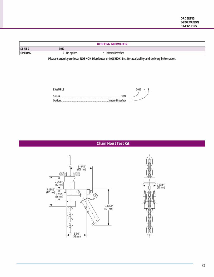
33
ORDERINGINFORMATIONDIMENSIONS
ORDERING INFORMATIONSERIES 3010OPTIONS 0 No options 1 Infrared interface
Please consult your local NOSHOK Distributor or NOSHOK, Inc. for availability and delivery information.
EXAMPLE
Series ...............................................................................................3010Option ...........................................................................Infrared interface
3010 – 1
Chain Hoist Test Kit
5-23/32″ (145 mm) 2-7/32″
(56 mm)
2-29/64″ (62 mm)
4-19/64″ (109 mm)
3-3/4″ (95 mm)
6-47/64″ (171 mm)
2-29/64″ (62 mm)
34
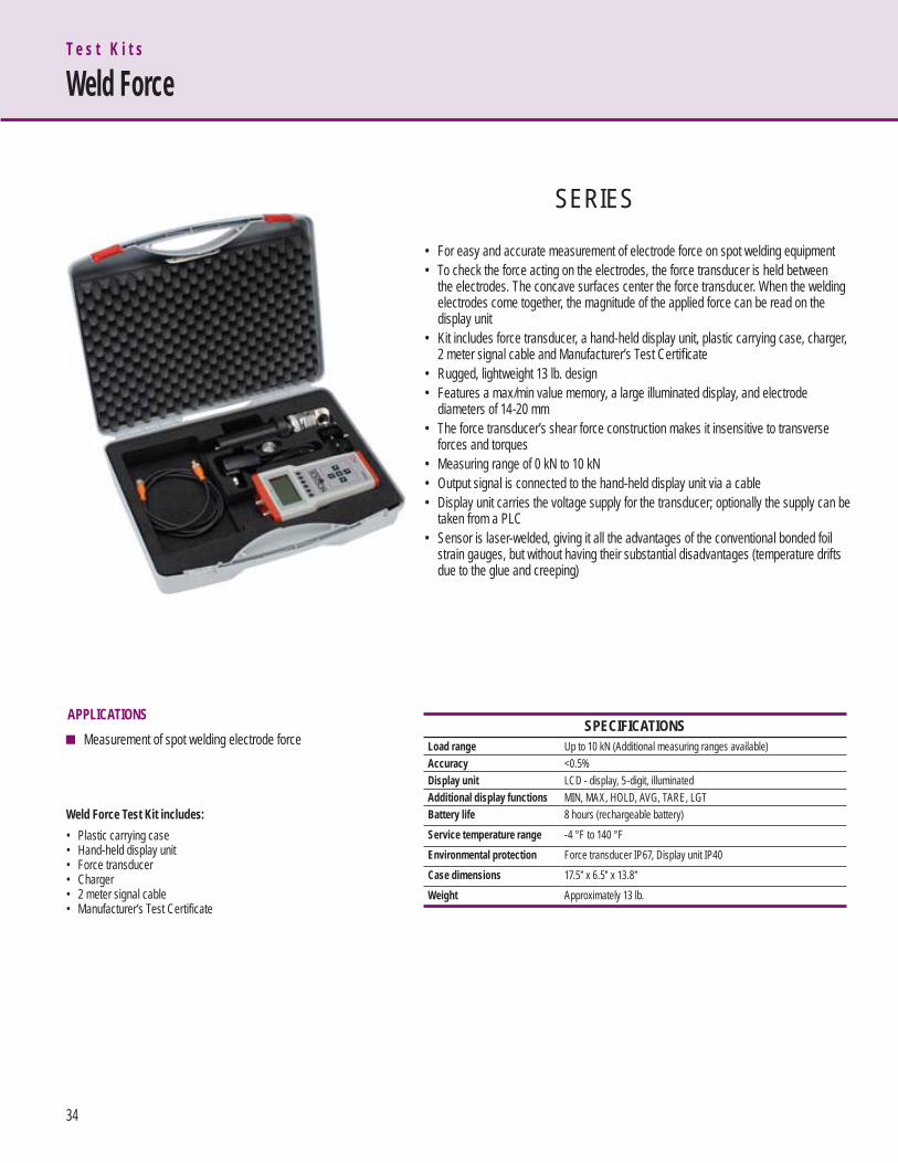
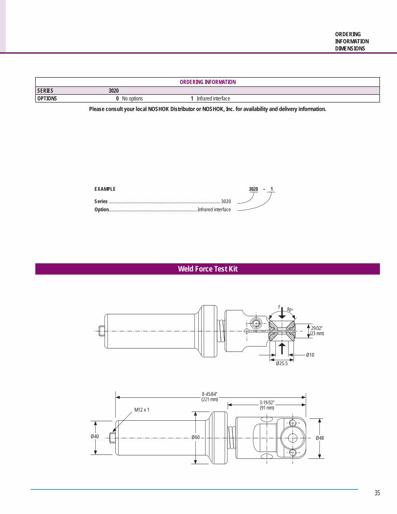
• For easy and accurate measurement of electrode force on spot welding equipment• To check the force acting on the electrodes, the force transducer is held between the electrodes. The concave surfaces center the force transducer. When the welding electrodes come together, the magnitude of the applied force can be read on the display unit• Kit includes force transducer, a hand-held display unit, plastic carrying case, charger, 2 meter signal cable and Manufacturer’s Test Certifi cate• Rugged, lightweight 13 lb. design• Features a max/min value memory, a large illuminated display, and electrode diameters of 14-20 mm• The force transducer’s shear force construction makes it insensitive to transverse forces and torques• Measuring range of 0 kN to 10 kN• Output signal is connected to the hand-held display unit via a cable• Display unit carries the voltage supply for the transducer; optionally the supply can be taken from a PLC• Sensor is laser-welded, giving it all the advantages of the conventional bonded foil strain gauges, but without having their substantial disadvantages (temperature drifts due to the glue and creeping)
T e s t K i t s
Weld Force
SPECIFICATIONSLoad range Up to 10 kN (Additional measuring ranges available)Accuracy <0.5%Display unit LCD - display, 5-digit, illuminatedAdditional display functions MIN, MAX, HOLD, AVG, TARE, LGTBattery life 8 hours (rechargeable battery)Service temperature range -4 °F to 140 °FEnvironmental protection Force transducer IP67, Display unit IP40Case dimensions 17.5″ x 6.5″ x 13.8″Weight Approximately 13 lb.
Measurement of spot welding electrode forceAPPLICATIONS
SERIES
Weld Force Test Kit includes:• Plastic carrying case• Hand-held display unit• Force transducer• Charger• 2 meter signal cable• Manufacturer’s Test Certificate
35
ORDERINGINFORMATIONDIMENSIONS
ORDERING INFORMATIONSERIES 3020OPTIONS 0 No options 1 Infrared interface
Please consult your local NOSHOK Distributor or NOSHOK, Inc. for availability and delivery information.
EXAMPLE
Series .............................................................................................. 3020Option ...........................................................................Infrared interface
3020 – 1
Weld Force Test Kit
F 90°
29/32″(23 mm)
Ø10Ø25.5
3-19/32″(91 mm)
8-45/64″(221 mm)
Ø40 Ø48
M12 x 1
Ø60
36
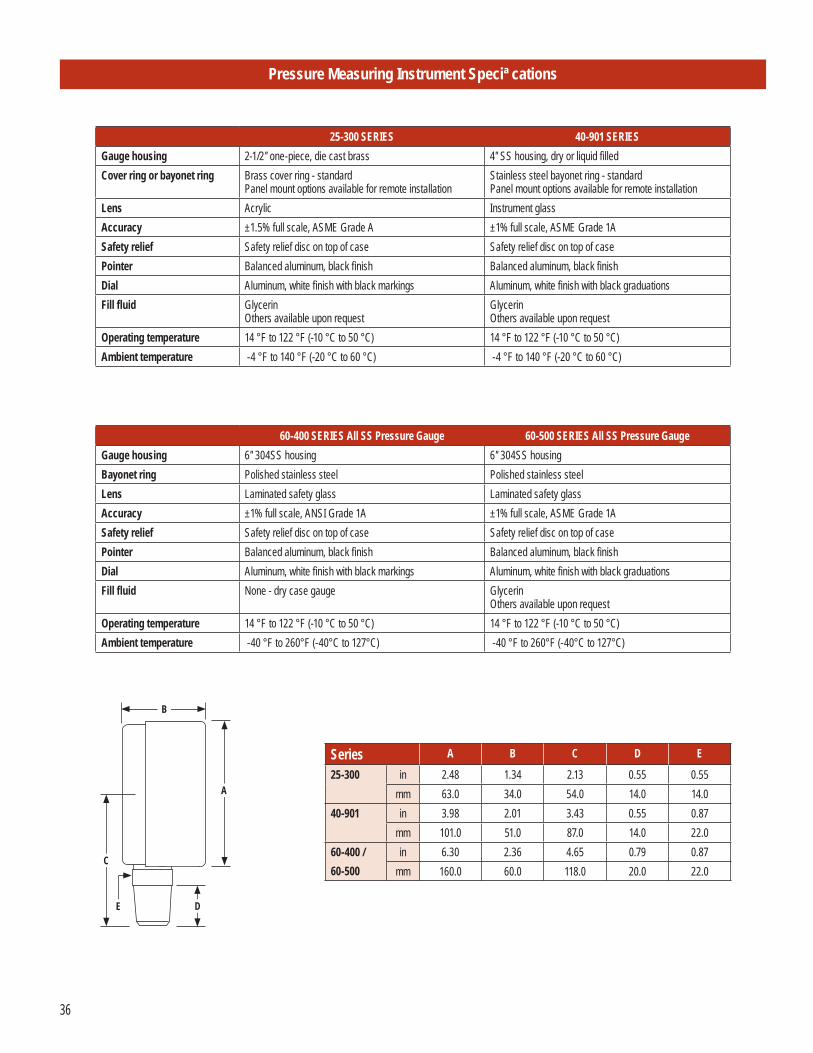
Pressure Measuring Instrument Speci cations
25-300 SERIES 40-901 SERIESGauge housing 2-1/2″ one-piece, die cast brass 4″ SS housing, dry or liquid filledCover ring or bayonet ring Brass cover ring - standard
Panel mount options available for remote installationStainless steel bayonet ring - standardPanel mount options available for remote installation
Lens Acrylic Instrument glassAccuracy ±1.5% full scale, ASME Grade A ±1% full scale, ASME Grade 1ASafety relief Safety relief disc on top of case Safety relief disc on top of casePointer Balanced aluminum, black finish Balanced aluminum, black finishDial Aluminum, white finish with black markings Aluminum, white finish with black graduationsFill fluid Glycerin
Others available upon requestGlycerinOthers available upon request
Operating temperature 14 °F to 122 °F (-10 °C to 50 °C) 14 °F to 122 °F (-10 °C to 50 °C)Ambient temperature -4 °F to 140 °F (-20 °C to 60 °C) -4 °F to 140 °F (-20 °C to 60 °C)
60-400 SERIES All SS Pressure Gauge 60-500 SERIES All SS Pressure GaugeGauge housing 6″ 304SS housing 6″ 304SS housingBayonet ring Polished stainless steel Polished stainless steelLens Laminated safety glass Laminated safety glassAccuracy ±1% full scale, ANSI Grade 1A ±1% full scale, ASME Grade 1ASafety relief Safety relief disc on top of case Safety relief disc on top of casePointer Balanced aluminum, black finish Balanced aluminum, black finishDial Aluminum, white finish with black markings Aluminum, white finish with black graduationsFill fluid None - dry case gauge Glycerin
Others available upon requestOperating temperature 14 °F to 122 °F (-10 °C to 50 °C) 14 °F to 122 °F (-10 °C to 50 °C) Ambient temperature -40 °F to 260°F (-40°C to 127°C) -40 °F to 260°F (-40°C to 127°C)
Series A B C D E
25-300 in 2.48 1.34 2.13 0.55 0.55mm 63.0 34.0 54.0 14.0 14.0
40-901 in 3.98 2.01 3.43 0.55 0.87mm 101.0 51.0 87.0 14.0 22.0
60-400 / 60-500
in 6.30 2.36 4.65 0.79 0.87mm 160.0 60.0 118.0 20.0 22.0
A
B
C
DE
37
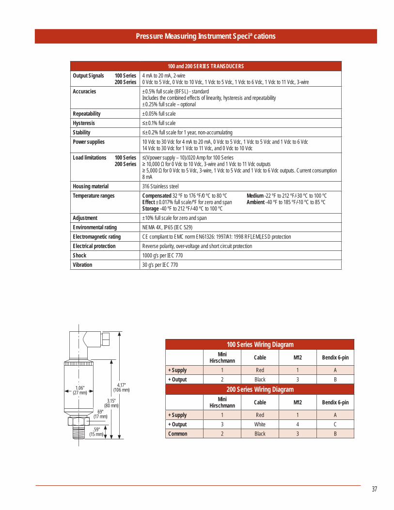
Pressure Measuring Instrument Speci cations
100 and 200 SERIES TRANSDUCERSOutput Signals 100 Series 200 Series
4 mA to 20 mA, 2-wire0 Vdc to 5 Vdc, 0 Vdc to 10 Vdc, 1 Vdc to 5 Vdc, 1 Vdc to 6 Vdc, 1 Vdc to 11 Vdc, 3-wire
Accuracies ±0.5% full scale (BFSL) - standardIncludes the combined effects of linearity, hysteresis and repeatability±0.25% full scale – optional
Repeatability ±0.05% full scale Hysteresis ≤±0.1% full scaleStability ≤±0.2% full scale for 1 year, non-accumulatingPower supplies 10 Vdc to 30 Vdc for 4 mA to 20 mA, 0 Vdc to 5 Vdc, 1 Vdc to 5 Vdc and 1 Vdc to 6 Vdc
14 Vdc to 30 Vdc for 1 Vdc to 11 Vdc, and 0 Vdc to 10 VdcLoad limitations 100 Series 200 Series
≤(Vpower supply – 10)/.020 Amp for 100 Series≥ 10,000 Ω for 0 Vdc to 10 Vdc, 3-wire and 1 Vdc to 11 Vdc outputs≥ 5,000 Ω for 0 Vdc to 5 Vdc, 3-wire, 1 Vdc to 5 Vdc and 1 Vdc to 6 Vdc outputs. Current consumption 8 mA
Housing material 316 Stainless steelTemperature ranges Compensated 32 ºF to 176 ºF/0 ºC to 80 ºC Medium -22 ºF to 212 ºF/-30 ºC to 100 ºC
Effect ±0.017% full scale/ºF for zero and span Ambient -40 ºF to 185 ºF/-10 ºC to 85 ºCStorage -40 ºF to 212 ºF/-40 ºC to 100 ºC
Adjustment ±10% full scale for zero and spanEnvironmental rating NEMA 4X, IP65 (IEC 529)Electromagnetic rating CE compliant to EMC norm EN61326: 1997/A1: 1998 RFI,EMI,ESD protectionElectrical protection Reverse polarity, over-voltage and short circuit protectionShock 1000 g’s per IEC 770Vibration 30 g’s per IEC 770
100 Series Wiring DiagramMini
Hirschmann Cable M12 Bendix 6-pin
+ Supply 1 Red 1 A+ Output 2 Black 3 B
200 Series Wiring DiagramMini
Hirschmann Cable M12 Bendix 6-pin
+ Supply 1 Red 1 A+ Output 3 White 4 CCommon 2 Black 3 B
1.06″(27 mm)
4.17″(106 mm)
69″(17 mm)
.59″(15 mm)
3.15″(80 mm)
38
Pressure Measuring Instrument Speci cations
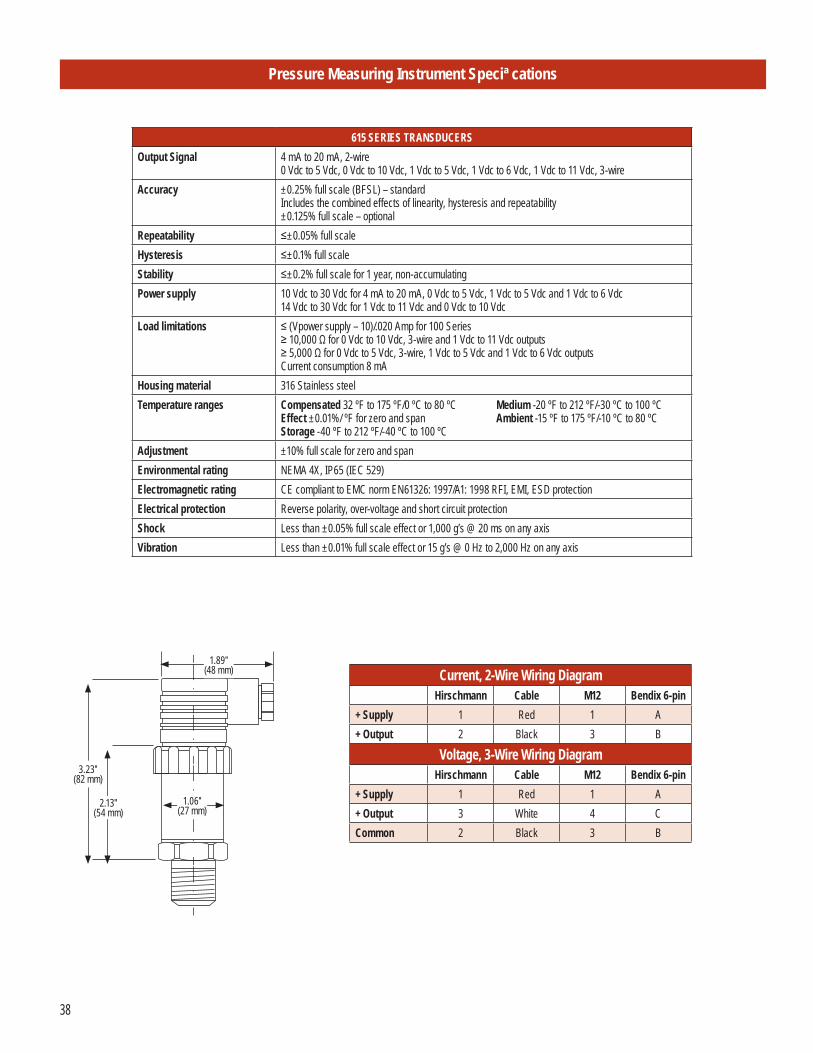
615 SERIES TRANSDUCERSOutput Signal 4 mA to 20 mA, 2-wire
0 Vdc to 5 Vdc, 0 Vdc to 10 Vdc, 1 Vdc to 5 Vdc, 1 Vdc to 6 Vdc, 1 Vdc to 11 Vdc, 3-wireAccuracy ±0.25% full scale (BFSL) – standard
Includes the combined effects of linearity, hysteresis and repeatability±0.125% full scale – optional
Repeatability ≤±0.05% full scaleHysteresis ≤±0.1% full scaleStability ≤±0.2% full scale for 1 year, non-accumulatingPower supply 10 Vdc to 30 Vdc for 4 mA to 20 mA, 0 Vdc to 5 Vdc, 1 Vdc to 5 Vdc and 1 Vdc to 6 Vdc
14 Vdc to 30 Vdc for 1 Vdc to 11 Vdc and 0 Vdc to 10 VdcLoad limitations ≤ (Vpower supply – 10)/.020 Amp for 100 Series
≥ 10,000 Ω for 0 Vdc to 10 Vdc, 3-wire and 1 Vdc to 11 Vdc outputs≥ 5,000 Ω for 0 Vdc to 5 Vdc, 3-wire, 1 Vdc to 5 Vdc and 1 Vdc to 6 Vdc outputsCurrent consumption 8 mA
Housing material 316 Stainless steelTemperature ranges Compensated 32 ºF to 175 ºF/0 ºC to 80 ºC Medium -20 ºF to 212 ºF/-30 ºC to 100 ºC
Effect ±0.01%/ ºF for zero and span Ambient -15 ºF to 175 ºF/-10 ºC to 80 ºC Storage -40 ºF to 212 ºF/-40 ºC to 100 ºC
Adjustment ±10% full scale for zero and spanEnvironmental rating NEMA 4X, IP65 (IEC 529)Electromagnetic rating CE compliant to EMC norm EN61326: 1997/A1: 1998 RFI, EMI, ESD protectionElectrical protection Reverse polarity, over-voltage and short circuit protectionShock Less than ±0.05% full scale effect or 1,000 g’s @ 20 ms on any axisVibration Less than ±0.01% full scale effect or 15 g’s @ 0 Hz to 2,000 Hz on any axis
1.89″(48 mm)
3.23″(82 mm)
2.13″(54 mm)
1.06″(27 mm)
Current, 2-Wire Wiring DiagramHirschmann Cable M12 Bendix 6-pin
+ Supply 1 Red 1 A+ Output 2 Black 3 B
Voltage, 3-Wire Wiring DiagramHirschmann Cable M12 Bendix 6-pin
+ Supply 1 Red 1 A+ Output 3 White 4 CCommon 2 Black 3 B
39
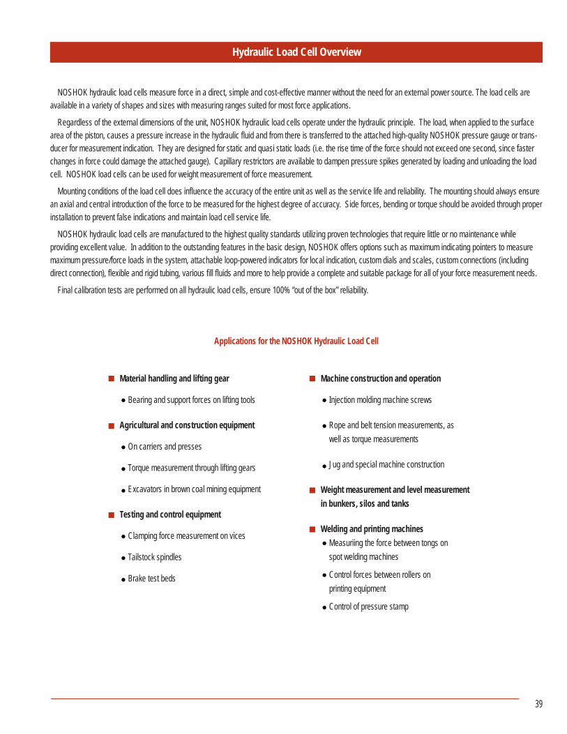
Hydraulic Load Cell Overview
NOSHOK hydraulic load cells measure force in a direct, simple and cost-effective manner without the need for an external power source. The load cells are available in a variety of shapes and sizes with measuring ranges suited for most force applications.
Regardless of the external dimensions of the unit, NOSHOK hydraulic load cells operate under the hydraulic principle. The load, when applied to the surface area of the piston, causes a pressure increase in the hydraulic fluid and from there is transferred to the attached high-quality NOSHOK pressure gauge or trans-ducer for measurement indication. They are designed for static and quasi static loads (i.e. the rise time of the force should not exceed one second, since faster changes in force could damage the attached gauge). Capillary restrictors are available to dampen pressure spikes generated by loading and unloading the load cell. NOSHOK load cells can be used for weight measurement of force measurement.
Mounting conditions of the load cell does influence the accuracy of the entire unit as well as the service life and reliability. The mounting should always ensure an axial and central introduction of the force to be measured for the highest degree of accuracy. Side forces, bending or torque should be avoided through proper installation to prevent false indications and maintain load cell service life.
NOSHOK hydraulic load cells are manufactured to the highest quality standards utilizing proven technologies that require little or no maintenance while providing excellent value. In addition to the outstanding features in the basic design, NOSHOK offers options such as maximum indicating pointers to measure maximum pressure/force loads in the system, attachable loop-powered indicators for local indication, custom dials and scales, custom connections (including direct connection), flexible and rigid tubing, various fill fluids and more to help provide a complete and suitable package for all of your force measurement needs.
Final calibration tests are performed on all hydraulic load cells, ensure 100% “out of the box” reliability.
Applications for the NOSHOK Hydraulic Load Cell
Material handling and lifting gear
Bearing and support forces on lifting tools
Agricultural and construction equipment
On carriers and presses
Torque measurement through lifting gears
Excavators in brown coal mining equipment
Testing and control equipment
Clamping force measurement on vices
Tailstock spindles
Brake test beds
Machine construction and operation
Injection molding machine screws
Rope and belt tension measurements, as well as torque measurements
Jug and special machine construction
Weight measurement and level measurement in bunkers, silos and tanks
Welding and printing machines Measuriing the force between tongs on spot welding machines
Control forces between rollers on printing equipment
Control of pressure stamp
40
Information Required for Level Measurement
Level Measurement: Standing/hanging container: (hanging container up to 60 ton total weight).The measuring unit is applicable for evenly distributed amounts (liquids).The dimensions in the distance have to be equal to each other and equal to the center.
• 3 point seating, shape of container; symmetric 1 force measuring unit, 2 fixed bearings 1/3 is measured
The indicated value is 3 times the measured value • 3 point seating, shape of container; symmetric 3 force measuring units
Values are measured under each container foot • 4 point seating, shape of container; symmetric 4 measuring units
Values are measured under each container foot
Weight of Container: Nominal capacity, nominal load:
Filling material: Weight density:
Lying containers:The measuring unit is applicable for evenly distributed amounts (liquids)Important: the containers must have a symmetric shape
• 3 point seating, shape of container; symmetric 1 force measuring unit, 2 fixed bearing 1/2 is measured
The load is distributed 50/50 • 4 point seating, shape of container; symmetric 4 force measuring units Values are measured under each container foot
Weight of Container: Nominal capacity, nominal load:
Filling material: Weight density:
Standing/lying containers for bulk material:The value indicated is calculated using 3 or 4 measuring values without a fixed bearing. The measuring values are transferredto a processing unit with tara/zero suppression. All load cells are linked to an indicator with the output corresponding to thesum of all measuring values and being displayed.
• 3 point seating Container with 3 force measuring units Values are measured under each container foot • 4 point seating Container with 4 force measuring units Values are measured under each container foot
Weight of Container: Nominal capacity, nominal load:
Filling material: Weight density:
Additional features required:
41
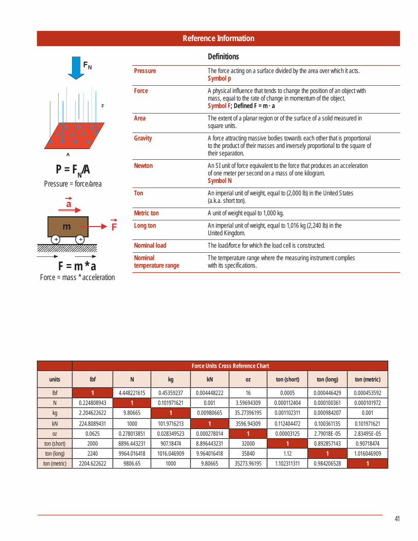
Reference Information
P = FN/APressure = force/area
F = m * aForce = mass * acceleration
Pressure The force acting on a surface divided by the area over which it acts. Symbol p
Force A physical influence that tends to change the position of an object with mass, equal to the rate of change in momentum of the object.
Symbol F; Defined F = m · a
Area The extent of a planar region or of the surface of a solid measured in square units.
Gravity A force attracting massive bodies towards each other that is proportional to the product of their masses and inversely proportional to the square of their separation.
Newton An SI unit of force equivalent to the force that produces an acceleration of one meter per second on a mass of one kilogram.
Symbol N
Ton An imperial unit of weight, equal to (2,000 lb) in the United States (a.k.a. short ton).
Metric ton A unit of weight equal to 1,000 kg.
Long ton An imperial unit of weight, equal to 1,016 kg (2,240 lb) in the United Kingdom.
Nominal load The load/force for which the load cell is constructed.
Nominal The temperature range where the measuring instrument compliestemperature range with its specifications.
Definitions
Force Units Cross Reference Chart
units lbf N kg kN oz ton (short) ton (long) ton (metric)
lbf 1 4.448221615 0.45359237 0.004448222 16 0.0005 0.000446429 0.000453592N 0.224808943 1 0.101971621 0.001 3.59694309 0.000112404 0.000100361 0.000101972kg 2.204622622 9.80665 1 0.00980665 35.27396195 0.001102311 0.000984207 0.001
kN 224.8089431 1000 101.9716213 1 3596.94309 0.112404472 0.100361135 0.101971621oz 0.0625 0.278013851 0.028349523 0.000278014 1 0.00003125 2.79018E-05 2.83495E-05
ton (short) 2000 8896.443231 907.18474 8.896443231 32000 1 0.892857143 0.90718474ton (long) 2240 9964.016418 1016.046909 9.964016418 35840 1.12 1 1.016046909
ton (metric) 2204.622622 9806.65 1000 9.80665 35273.96195 1.102311311 0.984206528 1

42
NOTES____________________________________________________________________________________
____________________________________________________________________________________
____________________________________________________________________________________
____________________________________________________________________________________
____________________________________________________________________________________
____________________________________________________________________________________
____________________________________________________________________________________
____________________________________________________________________________________
____________________________________________________________________________________
____________________________________________________________________________________
____________________________________________________________________________________
____________________________________________________________________________________
____________________________________________________________________________________
____________________________________________________________________________________
____________________________________________________________________________________
____________________________________________________________________________________
____________________________________________________________________________________
____________________________________________________________________________________
____________________________________________________________________________________
____________________________________________________________________________________
____________________________________________________________________________________

TO DOWNLOAD OR ORDER CATALOGS,VISIT WWW.NOSHOK.COM
NOSHOK is committed to providing
a high degree of value and continually improving processes to improve customer
satisfaction by focusing on customer requirements for the design, manufacture and
distribution of pressure, temperature, and force measurement instruments along with
needle and manifold valves including custom manifold systems for
industrial applications.

All from world class technology.
Combined with real-world stamina.
The highest value with the industry’s best warranty.
And all from a company with a 50+ year record of customer satisfaction.
All from your Single Source Instrumentation Company.
Catalog NK12FMS-1
Corporate Headquarters1010 West Bagley RoadBerea, Ohio 44017Ph: 440.243.0888Fax: 440.243.3472E-mail: [email protected]: www.noshok.com