for Mangaluru Integrated Gas...
61
Pre-Feasibility Report for Mangaluru Integrated Gas Project Submitted to: Ministry of Environment, Forests, and Climate Change (MoEF&CC) Submitted by: H-Energy Private Limited March, 2018
Transcript of for Mangaluru Integrated Gas...

Pre-Feasibility Report
for
Mangaluru Integrated Gas Project
Submitted to: Ministry of Environment, Forests, and Climate Change (MoEF&CC)
Submitted by:
H-Energy Private Limited
March, 2018

ii
Table of Contents Chapter 1 Executive Summary ............................................................................................................... 1
Chapter 2 Introduction and Project Background ..................................................................................... 2
2.1 Project Identification ...................................................................................................................... 2
2.1.1 Project Proponent ................................................................................................................... 2
2.2 Brief Description of the Nature of the Project ................................................................................ 3
2.3 Need for the Project and its Importance to the Region ................................................................. 6
2.4 Demand – Supply Economics ....................................................................................................... 7
2.4.1 Demand for Natural Gas ......................................................................................................... 8
2.4.2 Supply of Natural Gas ............................................................................................................. 8
2.4.3 Demand Supply Gap .............................................................................................................. 8
2.4.4 Local Scenario ........................................................................................................................ 9
2.5 Imports v/s Indigenous Production ................................................................................................ 9
2.6 Export Possibility ......................................................................................................................... 10
2.7 Domestic / Export Markets .......................................................................................................... 10
2.8 Employment Generation (Direct and Indirect) Due to the Project ............................................... 10
Chapter 3 Project Description ............................................................................................................... 11
3.1 Type of Project ............................................................................................................................ 11
3.2 Project Location ........................................................................................................................... 11
3.3 Details of Alternative Sites Considered ....................................................................................... 12
3.3.1 Concept Selection: Analysis of Alternatives ......................................................................... 13
3.4 Magnitude of Operation ............................................................................................................... 17
3.5 Process Schematics .................................................................................................................... 17
3.5.1 Unloading Operations ........................................................................................................... 17
3.5.2 Jetty ...................................................................................................................................... 18
3.5.3 LNG Re-gasification .............................................................................................................. 18
3.5.4 R-LNG Dispatch .................................................................................................................... 20
3.6 Raw Material Requirement .......................................................................................................... 20
3.7 Resource Optimisation ................................................................................................................ 21
3.8 Availability of Utilities ................................................................................................................... 21
3.8.1 Water Requirement ............................................................................................................... 21
3.8.2 Power Requirement .............................................................................................................. 21
3.9 Waste Management .................................................................................................................... 22
3.9.1 Solid and Liquid Waste Generation ...................................................................................... 22
3.9.2 Noise Emissions ................................................................................................................... 23
3.9.3 Emissions into the Atmosphere ............................................................................................ 23
3.10 Schematic Representation ........................................................................................................ 25
Chapter 4 Site Analysis ......................................................................................................................... 26
4.1 Connectivity ................................................................................................................................. 26
4.2 Land Form and Ownership .......................................................................................................... 27
4.3 Topography ................................................................................................................................. 28

iii
4.4 Existing Land Use Pattern ........................................................................................................... 30
4.5 Existing Infrastructure .................................................................................................................. 31
4.6 Soil Classification ........................................................................................................................ 31
4.7 Climatic Data from Secondary Sources ...................................................................................... 32
4.7.1 Draft Availability at Site ......................................................................................................... 32
4.7.2 Climatic Condition ................................................................................................................. 32
4.7.3 Rainfall .................................................................................................................................. 33
4.7.4 Wind Data ............................................................................................................................. 33
4.7.5 Wave ..................................................................................................................................... 34
4.7.6 Current .................................................................................................................................. 35
4.7.7 Sea Surface Temperature .................................................................................................... 35
4.7.8 pH ......................................................................................................................................... 35
4.7.9 Salinity .................................................................................................................................. 35
4.8 Social Infrastructure Available ..................................................................................................... 35
Chapter 5 Planning Brief ....................................................................................................................... 37
5.1 Planning Concept ........................................................................................................................ 37
5.2 Population Projection................................................................................................................... 38
5.3 Land Use Planning ...................................................................................................................... 39
5.4 Assessment of Infrastructure Demand ........................................................................................ 39
5.5 Amenities / Facilities .................................................................................................................... 39
Chapter 6 Proposed Infrastructure ........................................................................................................ 41
6.1 Industrial Area ............................................................................................................................. 41
6.2 Residential Area .......................................................................................................................... 41
6.3 Green Belt ................................................................................................................................... 41
6.4 Social Infrastructure ..................................................................................................................... 41
6.5 Connectivity ................................................................................................................................. 42
6.6 Drinking Water Management ....................................................................................................... 42
6.7 Fire Water Storage System Management ................................................................................... 43
6.8 Sewerage System ....................................................................................................................... 43
6.9 Industrial & Solid Waste Management ........................................................................................ 44
6.10 Power Requirement & Supply / Source ..................................................................................... 44
Chapter 7 Rehabilitation and Resettlement Plan (R & R) Plan ............................................................. 45
Chapter 8 Project Schedule and Cost Estimates .................................................................................. 46
8.1 Schedule ...................................................................................................................................... 46
8.2 Project Cost ................................................................................................................................. 46
Chapter 9 Analysis of Proposal ............................................................................................................. 48
Chapter 10 Applicable Codes and Standards ....................................................................................... 52
10.1 Codes and Standards Applicable to FSRU ............................................................................... 52
10.1 Codes and Standards Applicable to Pipeline ............................................................................ 54

iv
List of Figures
Figure 1: Proposed Mooring Arrangement of FSRU and LNG Carrier at Jetty # 9 ................................ 4 Figure 2: Route of Proposed Pipeline from Jetty # 9 to New Mangalore Port ........................................ 5 Figure 3: Demand Supply Balance of Natural Gas from 2012-13 to 2029-30 ........................................ 8 Figure 4: Satellite Image of Project Location ........................................................................................ 11 Figure 5: General Layout Drawing of New Mangalore Port .................................................................. 12 Figure 6: Satellite Image of Proposed R-LNG Pipeline ........................................................................ 12 Figure 7: Satellite Imagery of Sites Considered for Primary Evaluation ............................................... 14 Figure 8: Site Layout 1 - Lee Side of Southern Breakwater ................................................................. 14 Figure 9: Site Layout 2 - Outer Harbour Beyond Southern Breakwater ............................................... 15 Figure 10: Site Layout 3 - FSRU and Shuttle Vessel at Jetty # 9 ......................................................... 16 Figure 11: General Project Arrangement .............................................................................................. 17 Figure 12: Typical Process Flow Schematics ....................................................................................... 20 Figure 13: Schematic Representation of Regasification Process ......................................................... 25 Figure 14: Project Location ................................................................................................................... 26 Figure 15: Area within 10 km Radius of Project Site ............................................................................ 27 Figure 16: Topography Sheet ............................................................................................................... 28 Figure 17: Recent Site Photographs ..................................................................................................... 30 Figure 18: Soil Characterisation in Karnataka State ............................................................................. 32 Figure 19: Annual Windrose Diagram ................................................................................................... 34 Figure 20: Core Project Influence Area (5km Radius) .......................................................................... 37
List of Tables
Table 1: Typical Vessel Dimensions of an FSRU ................................................................................... 5 Table 2: Typical Vessel Dimensions of an LNG Shuttle Vessel ............................................................. 6 Table 3: Demand Supply Gap of Natural Gas (2012-13 to 2029-30) ..................................................... 9 Table 4: Industrial Demand for Natural Gas in Mangaluru ..................................................................... 9 Table 5: Project Location ...................................................................................................................... 11 Table 6: Details of Sites Evaluated ....................................................................................................... 13 Table 7: Vaporizing Systems in Major LNG Terminals in India ............................................................ 19 Table 8: Route of Proposed Pipeline .................................................................................................... 28 Table 9: Conditions at location of the proposed LNG jetties in the sea ................................................ 28 Table 10: Existing Land Use Pattern .................................................................................................... 30 Table 11: Rainfall in Mangaluru ............................................................................................................ 33 Table 12: Wind Data for Mangaluru ...................................................................................................... 34 Table 13: Project Cost Estimate ........................................................................................................... 47

v
Glossary
AAV Ambient Air Vaporizer
BOG Boil Off Gas
CAGR Compounded Annual Growth Rate
CGD City Gas Distribution
EIA & RA Environmental Impact Assessment & Risk Assessment
FSRU Floating Storage Regasification Unit
GHG Green House Gasses
HEGPL H-Energy Gateway Private Limited
HEPL H-Energy Private Limited
IFV Intermediate Fluid Vaporizer
JMPL Jaigarh Mangalore Natural Gas Pipeline
KIOCL Kudremukh Iron Ore Company Limited
KG D6 Krishna – Godavari Basin Field Dhirubhai 6
LNG Liquefied Natural Gas
MIGP Mangalore Integrated Gas Project
MCFL Mangalore Chemicals and Fertilisers Limited
MMSCMD Million Metric Standard Cubic Meter Gas per Day
MMTPA Million Metric Tonnes per Annum
MRPL Mangalore Refineries and Petrochemicals Limited
MSEZ Mangalore Special Economic Zone
MSEZL Mangalore Special Economic Zone Limited
NMP New Mangalore Port
NMPT New Mangalore Port Trust
OLV Open Loop Vaporizer
OMPL ONGC Mangalore Petrochemicals Limited
ORV Open Rack Vaporizer
PFR Pre – Feasibility Report
PNGRB Petroleum and Natural Gas Regulatory Board
RCC Reinforced Concrete Cement
R-LNG Re-gasified Liquefied Natural Gas
SCV Submerged Combustion Vaporizer

vi
SEZ Special Economic Zone
STS Ship to Ship (Transfer)

1
______________________________________________________________________________________ Pre-Feasibility Report for Mangaluru Integrated Gas Project
Chapter 1 Executive Summary H-Energy Private Limited (HEPL), a Hiranandani Group Company, proposes to set up a Floating
Storage and Regasification Unit (FSRU) based LNG handling facility at New Mangalore Port. The
terminal will have an initial capacity of 1.5 million tonnes per annum (MMTPA), which can be
expanded to 3 MTPA. The New Mangalore Port Trust (NMPT) has extended their permission to H-
Energy to carry out feasibility and Environmental Impact Assessment Studies for the setting up of this
project.
This study indicates that Mangalore port is an existing port without ecologically critical habitats in the
vicinity. At the same time, it is a highly industrialized area and has been rated as the most polluted
location within the state of Karnataka. A moratorium on expansion / addition of industries in
Mangalore was lifted in 2012, after an action plan to improve environmental quality by the local
industries was submitted to the regulatory authorities. The proposed project will reduce existing
pollution in Mangalore with the availability of clean fuel to the existing industries.
As per this study, there are no environmental regulations that prohibit this activity and a detailed EIA
study indicating minimal impacts could lead to environmental clearance. Social acceptance of the
project is required, as environmental awareness is strong amongst the local population, especially the
fishing industry.
The proposed marine facilities, storage facilities, re-gasification facilities and other supporting facilities
been reviewed for establishing the environmental aspects. Three locations were considered for siting
the LNG berth in the Detailed Feasibility Report and Jetty # 9 located within New Mangalore Port, an
existing Jetty, currently handling LPG, Edible Oils and POLs has been determined to be the most
suitable location to set up this project and is expected to have minimum impact on the environment.
The Regasified LNG is proposed to be evacuated from the FSRU through an R-LNG Pipeline which
shall be laid from Jetty # 9 within New Mangalore Port and shall traverse along the existing elevated
pipe rack which is owned and operated by the Mangalore Special Economic Zone Ltd. (MSEZL). The
proposed pipeline shall be ~ 15 km long and shall deliver R-LNG to various industrial customers up to
the Mangalore Special Economic Zone.
This PFR is submitted in support of HEPL’s submission of Form I in accordance to EIA notification,
2006 and provides detailed information regarding the establishment of an LNG handling facility at
New Mangalore Port and its associated facilities.

2
______________________________________________________________________________________ Pre-Feasibility Report for Mangaluru Integrated Gas Project
Chapter 2 Introduction and Project Background
2.1 Project Identification
H-Energy Private Limited (HEPL), a company established with a vision to contribute to the economic
growth of the country by offering world class, environmentally safe and sustainable energy solutions,
intends to develop Liquefied Natural Gas (LNG) Handling Facilities at New Mangalore Port (NMP).
HEPL has been authorised by the Petroleum and Natural Gas Regulatory Board (PNGRB) to lay,
build, operate, and expand a 635 km long Natural Gas Pipeline from Jaigarh Port in Maharashtra to
Mangaluru in Karnataka vide Authorization Letter No. Infra/PL/NGPL/BID/JMPL/01/2016 dated
28.06.2016 thereby enabling the supply of eco-friendly Natural Gas to customers located in coastal
Maharashtra, Goa, and Karnataka. This project operates by the name of Jaigarh Mangalore Natural
Gas Pipeline (JMPL).
Keeping in mind the imminent demand for Natural Gas in Mangaluru, HEPL has conceptualised the
Mangaluru Integrated Gas Project (MIGP) and proposes to set up an FSRU based LNG Storage and
Regasification terminal of ~ 3.0 MMTPA capacity at Jetty # 9 within NMP. The MIGP proposes to
receive LNG via LNG Shuttle Vessels and re-gasify it into R-LNG on board the FSRU moored at
NMP. The R-LNG shall then be evacuated to various potential customers up to the Mangalore Special
Economic Zone (MSEZ) via an ~ 15 km long Natural Gas pipeline (hereinafter referred to as the
“Project”).
The envisaged project is strategic in nature and when implemented, will benefit not only the various
gas consuming industries in Mangaluru but will also benefit the common man by giving access to a
cleaner burning fuel for domestic consumption in the future.
The objective of this PFR is to furnish detailed information regarding HEPL’s envisaged project in
order to obtain an Environmental Clearance (EC) from the Ministry of Environment, Forests, and
Climate Change (MoEF&CC).
2.1.1 Project Proponent
HEPL is a part of the Hiranandani Group, a fast growing, well diversified organisation, with presence
in real estate, education, healthcare, hospitality, entertainment and retail. The Hiranandani Group is
best known for the activities of its flagship business – Real Estate Construction. Some of the group’s
marquee projects include Hiranandani Gardens, Powai, Hiranandani Meadows and Hiranandani
Estate, Thane, Hiranandani Business Park Powai & Thane, Hiranandani Upscale Chennai and
Bangalore, Hiranandani Upscale SEZ and Residential, Hyderabad, Hiranandani Palace Gardens,
Chennai, and 23 Marina, Dubai

Introduction and Project Background 3
______________________________________________________________________________________ Pre-Feasibility Report for Mangaluru Integrated Gas Project
H-Energy Gateway Private Limited (HEGPL), an affiliate of HEPL, is currently developing an LNG
FSRU based LNG terminal at Jaigarh Port in Maharashtra and a cross-country pipeline required to
connect the source to the National Gas Grid.
Other affiliates of HEPL are involved in the business of providing natural gas solutions including LNG
Sourcing, re-gasification facilities, downstream deliveries based on customer preference. H-Energy
and its various affiliates endeavour to build world-class LNG infrastructure projects, which will ensure
a regular and sustainable supply of clean, environment-friendly natural gas fuel at strategic locations
in India.
2.2 Brief Description of the Nature of the Project
The proposed Project forms a part of an integrated gas project envisaged in Mangaluru. The minimum
facilities anticipated for the realization of LNG handling facilities, but not limited to shall be following:
i. Marine Facilities:
a. Unloading and mooring facilities
b. Modification of existing Jetty, trestle and associated facilities
ii. LNG Carrier Vessels:
a. Shuttle Vessel with appropriate storage tanks for of transport of LNG from a suitable
terminal to NMP
b. FSRU with re-gasification facilities viz. Vaporizers, Pumps, Electrical,
Instrumentation, Control & Monitoring system and other equipment / facilities.
iii. Utilities:
a. Power System
b. Nitrogen System
c. Instrument / Plant Air System
d. Fire, Gas & Spill system
e. Fire Water System
iv. Associated Civil Works:
a. Jetty Strengthening (if needed)
b. Equipment Foundations
c. Roads
v. Construction of R-LNG Evacuation Pipeline:
The Project essentially plans to:
1. Berth an FSRU of up to 50,000 m3 capacity at Jetty # 9 within NMP with a maximum re-
gasification capacity of 3 MMTPA.

Introduction and Project Background 4
______________________________________________________________________________________ Pre-Feasibility Report for Mangaluru Integrated Gas Project
2. A Shuttle Vessel of up to 50,000 m3 capacity transporting LNG will be berthed alongside the
FSRU.
Figure 1: Proposed Mooring Arrangement of FSRU and LNG Carrier at Jetty # 9
3. LNG from the Shuttle Vessel shall be transferred to the FSRU via Ship to Ship Transfer (STS)
operations.
4. LNG will be re-gasified using vaporisers installed on board the FSRU.
5. This RLNG will be offloaded from the FSRU using Gas Unloading Arms installed onshore at
Jetty # 9.
6. Additionally provision for a Liquid Unloading Arm capable of evacuating LNG shall also be
created for future use.

Introduction and Project Background 5
______________________________________________________________________________________ Pre-Feasibility Report for Mangaluru Integrated Gas Project
Figure 2: Route of Proposed Pipeline from Jetty # 9 to New Mangalore Port
7. From the interface point of the Unloading Arm on shore, R-LNG shall be supplied to end
users in Mangalore and its vicinity through an ~ 18” OD x ~ 15 km long Natural Gas pipeline.
8. The R-LNG Pipeline will originate at its take-off point on Jetty # 9 and shall extend ~ 2 km
with NMP territory.
9. The pipeline shall then enter an existing Pipe Rack which is owned and operated by
Mangalore Special Economic Zone Limited (MSEZL) near Gate # 2 of NMP.
10. The pipeline shall then traverse ~ 15 km along the MSEZL’s Elevated Pipe Rack which is in a
designated pipeline corridor (for which EC has previously been granted by MoEF&CC) and
shall deliver Natural Gas to customers up to the MSEZ.
Typical vessel dimensions of the FSRU have been summarised in Table 1 below:
Table 1: Typical Vessel Dimensions of an FSRU
Parameter Value Units
Overall Length 195.3 m
Length between Perpendiculars
184.8 M
Depth (Moulded) 20 M
No. of On board Storage Tanks
3 Nos.
Storage Tank Dimensions ~ 50,000 M3
Type of Vaporisers Closed Loop System
Vaporiser Capacity 0.5 – 4 MMTPA
Typical vessel dimensions of the LNG Shuttle Vessel have been summarised in Table 2 below:

Introduction and Project Background 6
______________________________________________________________________________________ Pre-Feasibility Report for Mangaluru Integrated Gas Project
Table 2: Typical Vessel Dimensions of an LNG Shuttle Vessel
Parameter Value Units
Overall Length 195.3 m
Length between Perpendiculars
184.8 M
Depth (Moulded) 20 M
No. of On board Storage Tanks
3 Nos.
Storage Tank Dimensions ~ 50,000 M3
The proposed target date for commissioning of this project is 2020. NMP is well equipped to handle
bulk, liquid chemicals, hazardous cargoes, crude and POL products, heavy lifts, machinery and
containers. Currently, Jetty # 9 is handling LPG / Edible Oil / POL products. If an LNG Terminal is set
up at this location, existing traffic would be re-routed to Jetty # 12, Jetty # 13 which also handles the
same products.
2.3 Need for the Project and its Importance to the Region
Energy usage across the world is constantly changing. With the world's growing population, energy
supply is increasingly playing a vital role in improving standards of living. Since a little over the last
century, mankind has had an increased dependence on fossil fuels - especially on imported coal, oil
and natural gas in many parts of the world.
Natural gas supplies 22% of the energy used worldwide, and makes up nearly a quarter of electricity
generation, as well as playing a crucial role as a feedstock for industry. Natural gas is also a versatile
fuel and its growth is linked in part to its environmental benefits relative to other fossil fuels,
particularly for air quality as well as greenhouse gas emissions.
Currently, the role of Natural Gas in India’s energy basket is limited: comprising only 6% in 2016.
However, the Government of India has declared its vision to transition India into a gas-based
economy and raise the share of natural gas in the energy mix to 15% by 2022.
Mangalore has a unique position vis-à-vis the future demand and supply matrix of LNG. Mangalore is
a fast-growing industrial hub with presence of MRPL, OMPL and MSEZL housing various industries
and petrochemical complexes.
Additionally, Mangalore hosts an iron ore industry - KIOCL, fertilizer industry - MCFL and their
ancillary industrial units. Currently, these industries use heavy liquid sources like fuel oil and naphtha
for their energy and feedstock needs. Considering the growing demand of energy coupled with
increasing focus on environment, there is a strong case for environment-friendly LNG replacing these
polluting fuels.

Introduction and Project Background 7
______________________________________________________________________________________ Pre-Feasibility Report for Mangaluru Integrated Gas Project
As such, the Mangalore region rides on a virgin LNG demand of ~ 3 MMTPA. The demand for Gas
and LNG is sustainable, expected to grow significantly with the expansion plans of industries. Once
the gas pipeline infrastructure is in place, Mangalore region will get connected to all neighbouring
states. The coastal location of Mangalore also has a strategic advantage of readily available all-
season operating port with favourable marine conditions and proximity to existing and upcoming
global supply sources of LNG.
Local industries in Mangaluru viz. MCFL, MRPL, OMPL have been seeking access to Natural Gas to
be used as a cleaner alternative feedstock for their operations. Furthermore, a lack of access to
Natural Gas results in a continued use of heavier hydrocarbons viz. Naphtha, Fuel Oil, Diesel for its
operations resulting in high levels of GHG emissions.
The key factors influencing the need of exploring the possibility of LNG regasification terminal in the
Mangalore catchment are several, including:
Mangalore houses some of the key Bulk industries of the region viz. MRPL, MCFL, OMPL
etc.
The expanding MSEZ is believed to bring in tremendous industrial growth in the region. The
fuel requirements of the region are foreseen to be growing significantly in near future as a
result of the industrial growth.
Furthermore, the upcoming pipeline networks in Karnataka are likely to integrate the bulk
industries in the state to the national gas grid, thereby creating several opportunities for gas
trading.
Mangalore region is a lucrative gas market not only because of the size of demand but also
due to the character of the demand. The demand in the region is largely driven by the
Refining / Petrochemical & Industrial segments, which are most suited RLNG customers due
to their higher price affordability.
PNGRB is coming up with a list of several CGDs in the across various cities in India including
Karnataka. CGD segment has higher affordability of gas price and hence is a potential
segment for LNG demand.
An LNG handling facility at Mangalore can also act as a hub for supplying LNG (through LNG
Tankers) as bunker fuel for marine applications or to L-CNG stations to supply fuel for
vehicles along National Highways.
With the GoI’s target to implement Euro VI norms by 2020, LNG emerges as a cleaner and
economically more viable option for transportation applications.
2.4 Demand – Supply Economics
The consumption of Natural Gas in India is majorly driven by five sectors:

Introduction and Project Background 8
______________________________________________________________________________________ Pre-Feasibility Report for Mangaluru Integrated Gas Project
a) Fertilizer (34% of total gas demand in fiscal year 2015-16),
b) Electric power (23%),
c) Refining (11%),
d) City gas distribution, including transport (11%),
e) Petrochemical (8%) industries
2.4.1 Demand for Natural Gas
According to the PNGRB’s Vision for Natural Gas 2030, in recent years the demand for natural gas in
India has increased significantly due to its higher availability, development of transmission and
distribution infrastructure, the savings from the usage of natural gas in place of alternate fuels, the
environment friendly characteristics of natural gas as a fuel and the overall favourable economics of
supplying gas at reasonable prices to end consumers. In future, the natural gas demand is all set to
grow significantly at a CAGR of 6.8% from 242.6 MMSCMD in 2012-13 to 746 MMSCMD in 2029-30.
2.4.2 Supply of Natural Gas
The same report states that the supply of natural gas is likely to increase in future with the help of
increase in domestic gas production and imported LNG. However, the expected increase in domestic
production at present is significantly lower than earlier projections due to a steady reduction in gas
output from the KG D6 field. The total supply of natural gas is expected to grow at a CAGR of 7.2%
from 2012 to 2030 reaching 400 MMSCMD by 2021-22 and 474 MMSCMD by 2029-30.
2.4.3 Demand Supply Gap
Figure 3: Demand Supply Balance of Natural Gas from 2012-13 to 2029-30

Introduction and Project Background 9
______________________________________________________________________________________ Pre-Feasibility Report for Mangaluru Integrated Gas Project
The country faces a widening gap between indigenous gas production and demand. Due to the
unavailability of domestic sources of Natural Gas, it can be determined that this gap is met by
imported LNG. The Demand – Supply Gap can be observed in Figure 3 above. This has also been
summarised in Table 3 below:
Table 3: Demand Supply Gap of Natural Gas (2012-13 to 2029-30)
2012-13 2016-17 2021-22 2026-27 2029-30
(in MMSCMD)
Domestic Sources 101.1 156.7 182 211 230
LNG Imports 44.6 143 188 214 214
Gas Imports (Cross border pipelines) 0 0 30.0 30.0 30.0
Total Supply 145.7 299.7 400 454 474
Total Demand 242.6 378.06 516.97 654.55 746
Demand Supply Gap (-) 96.9 (-) 78.36 (-) 116.97 (-) 200.55 (-) 272
As seen above, the demand-supply gap justifies the need for additional infrastructure. Demand for
Natural Gas is increasing as it is a clean-burning fuel and with the expanding network of pipelines,
fuel is available with minimal transportation costs. NG can be connected to the National Grid and can
be supplied across Karnataka, Goa and Maharashtra. Considering this growing demand of Natural
Gas in the markets along the Western Coast of India and to facilitate the supply, HEPL has decided to
pursue the opportunity of setting up an FSRU in the NMP.
2.4.4 Local Scenario
Table 4 below shows a summary of the local industrial demand at Mangaluru:
Table 4: Industrial Demand for Natural Gas in Mangaluru
S. No. Potential Customer Demand (in MMSCMD) Current Supply
1 MCFL 1.00 -
2 MRPL 3.83 -
3 OMPL 0.42 -
Total 5.25 -
Mangaluru has an immediate industrial demand of 5.25 MMSCMD (~ 1.5 MMTPA) of Natural Gas.
The local demand has the potential to increase upwards given that the availability of Natural Gas in
the region will incentivise industrial development. Furthermore, availability of Natural Gas would also
pave the way for CGD in the region in the future. It is therefore evident that developing India’s Natural
Gas transmission infrastructure is imperative to narrow the demand-supply gap of this commodity.
2.5 Imports v/s Indigenous Production

Introduction and Project Background 10
______________________________________________________________________________________ Pre-Feasibility Report for Mangaluru Integrated Gas Project
The Project envisages coastal cargo shipments of LNG arriving at NMP from Jaigarh in Maharashtra.
The regasification of LNG is expected to be done within the Port as envisaged in this project and shall
be supplied via the Natural Gas pipeline directly to customers.
As this project is expected to create the infrastructure that enables Natural Gas availability in the
region, indigenous production is beyond the scope of this project.
2.6 Export Possibility
The Project is intended to develop local Natural Gas distribution infrastructure. Export of Natural Gas
requires the creation of specialised facilities which have not been envisaged at this stage of the
project.
2.7 Domestic / Export Markets
The Project is envisaged to enable transmission of Natural Gas within Karnataka and neighbouring
states viz. Goa and Maharashtra. The Project is essentially intended to cater to local / domestic
demand and does not envisage exports.
2.8 Employment Generation (Direct and Indirect) Due to the Project
With globalization, Indian industries are now opening to the world, resulting in growing demand for
world-class quality workmanship and deployment of latest technologies to enhance technical skill and
productivity. Intense training to workforce and equipping them with required knowledge and skill will
ensure quality and higher level of productivity of men and machines. Keeping this objective in view
HEPL can provide vocational training for enhancement in skills to the unemployed youths in the study
area in order to develop their skills, knowledge and appropriate qualifications which will lead the way
to decent employment.
The proposed development would have beneficial impacts through provision of additional direct and
indirect employment opportunities. At the time of construction and operational phases, there would be
increase in skilled, semi-skilled and unskilled work force. It is imperative that local people would be
employed based on their skills and educational qualifications.
The Project is expected to generate employment for roughly 50 – 200 people directly and indirectly.
Further, natural gas, being a cleaner fuel, will replace some of FO, Naphtha and Diesel requirements
as a fuel source. Industries dependent on LNG will develop in Western India generating addition
employment in the future.

11
______________________________________________________________________________________ Pre-Feasibility Report for Mangaluru Integrated Gas Project
Chapter 3 Project Description
3.1 Type of Project The proposed Project falls under Category ‘A’, Schedule 6(a) “Oil & gas transportation pipe line
(crude and refinery/ petrochemical products), passing through national parks / sanctuaries / coral
reefs / ecologically sensitive areas including LNG Terminals” as per EIA Notification dated September
14th 2006 and its amendments.
3.2 Project Location The Project envisages an FSRU, permanently moored at Jetty # 9 of NMP. The FSRU shall be double
banked with a Shuttle Vessel which shall offload LNG to the FSRU. R-LNG shall be evacuated from
the vessel using unloading arms installed on the Jetty. The co-ordinates of the project location have
been provided in the table below.
Table 5: Project Location
S. No. Location Latitude Longitude
1 FSRU and LNG Shuttle Vessel Mooring Location: Jetty# 9 (New Jetty # 13) 12°55'23.50"N 74°48'36.31"E
2 Take Off Point of R-LNG Pipeline at Jetty # 9, NMP
3 Termination Point of R-LNG Pipeline at MSEZ 13°0'2.02"N 74°51'33.38"E
A Satellite Image of the selected site for mooring the FSRU, LNG Shuttle Vessel and the proposed
location for the truck loading gantry is shown in Figure 4 below.
Figure 4: Satellite Image of Project Location
A General Layout of the New Mangalore Port is shown in Figure 5 below.

Project Description 12
______________________________________________________________________________________ Pre-Feasibility Report for Mangaluru Integrated Gas Project
Figure 5: General Layout Drawing of New Mangalore Port
A Satellite Image indicating the route of the proposed R-LNG pipeline from Jetty # 9 within NMP up to
MSEZ is shown in Figure 6 below:
Figure 6: Satellite Image of Proposed R-LNG Pipeline
3.3 Details of Alternative Sites Considered In order to identify the best technical solution, a preliminary concept selection and feasibility study has
been carried out. Different alternatives have been analysed, both in terms of technical solutions to be
adopted, and of potential locations of the FSRU. The analysis of the alternatives has been focused on
the identification of the best solution(s) to:
Guarantee high operability, according to local conditions;

Project Description 13
______________________________________________________________________________________ Pre-Feasibility Report for Mangaluru Integrated Gas Project
Guarantee relevant technical performances;
Minimize potential impacts on the environment;
Minimize associated costs.
It has to be highlighted that the realization of an offshore LNG Terminal (FSRU) involves the following
main advantages:
a) Realization of an offshore LNG Terminal (FSRU), if compared to an onshore one, minimizes
potential environmental impacts;
b) Realization of an offshore LNG Terminal (FSRU), if compared to an onshore one, involves
safety risk minimization, due to the absence of areas potentially affected by human presence
in the proximity of the FSRU itself;
c) Installation of an FSRU (if compared to fixed offshore LNG Terminals) involves less
criticalities during the decommissioning. In fact, decommissioning of the regasification unit
only consists on its removal from the location and its transfer to a dedicated shipyard, with
decommissioning activities and associated environmental impacts minimization.
3.3.1 Concept Selection: Analysis of Alternatives
In order to define the best FSRU location, the following topics have been taken into consideration:
Meteo-marine conditions (to guarantee high operability of the system);
Absence of physical and environmental constraints;
Safety Risks and impacts on the environment and population
On this basis, three locations were preliminarily investigated. These included:
Table 6: Details of Sites Evaluated
S. No. Site Considered Latitude Longitude
1. Lee side of the Southern Breakwater 12°55'17.30"N 74°48'10.00"E
2. Outer harbour beyond Southern Breakwater
12°55'7.03"N 74°48'21.08"E
3. Jetty # 9 12°55'23.50"N 74°48'36.31"E
Satellite imagery of the sites considered for primary evaluation of prospective project locations are
shown in Figure 6 below:

Project Description 14
______________________________________________________________________________________ Pre-Feasibility Report for Mangaluru Integrated Gas Project
Figure 7: Satellite Imagery of Sites Considered for Primary Evaluation
1. Lee Side of Southern Breakwater
This layout comprises double banking of FSRU and the Shuttle Vessel in the lee side of the
Southern Breakwater.
Figure 8: Site Layout 1 - Lee Side of Southern Breakwater

Project Description 15
______________________________________________________________________________________ Pre-Feasibility Report for Mangaluru Integrated Gas Project
This option has been discarded as a potential location for setting up of this project as:
a) Existing tankages on the backup land of Jetty # 9 are close to the LNG unloading
operations. Detailed studies would need to be carried out to ascertain the level of risk
and possible mitigation measures like removal of tank farms, providing water curtains
to reduce the exclusion zone distance etc.
b) There may be a requirement for construction of an additional turning basin for the
FSRU berthing and un-berthing.
c) Capital dredging will be required for the additional turning and berthing basin which is
estimated at about 2.5 million m3.
d) As the Shuttle Vessel and FSRU would be berthed in the area where the effect of
waves, current and passing vessels will be greater than the berths inside the harbour,
dredging depths will be deeper than the options inside the harbour and have been
estimated to -15.4m CD to maintain the design depths of the existing channel.
e) Tranquillity has been studied for the FSRU and may need extension of existing
breakwaters for the same.
f) As the dredging needs to be undertaken very close to breakwater, the stability of the
sea wall and breakwater also needs to be assessed in greater detail.
2. Outer Harbour beyond Southern Breakwater
The location of this layout is in the outer harbour of New Mangalore Port.
Figure 9: Site Layout 2 - Outer Harbour Beyond Southern Breakwater
Project Description 16
______________________________________________________________________________________ Pre-Feasibility Report for Mangaluru Integrated Gas Project
This option has been discarded as a potential location for setting up of this project as:
a) This layout is located outside the port’s breakwater. An additional breakwater of ~ 2
km length would be required to be constructed on the southern side of the port area
to create a separate protected harbour for LNG operations.
b) An approach channel of appropriate width would be needed to access the terminal
area.
c) An adequate turning circle of would also be required for turning the ship inside the
harbour area.
d) Since this will be a green field development, intensive capital dredging, reclamation
and breakwater construction would be required.
e) The dredged depth has been calculated up to -15.4m CD and the total volume of
dredging in this option is estimated at about 9 Million m3.
f) The estimated reclamation quantity is about 1 million m3.
g) Due to extensive dredging and new breakwater construction this is the least preferred
option from environmental impact point of view.
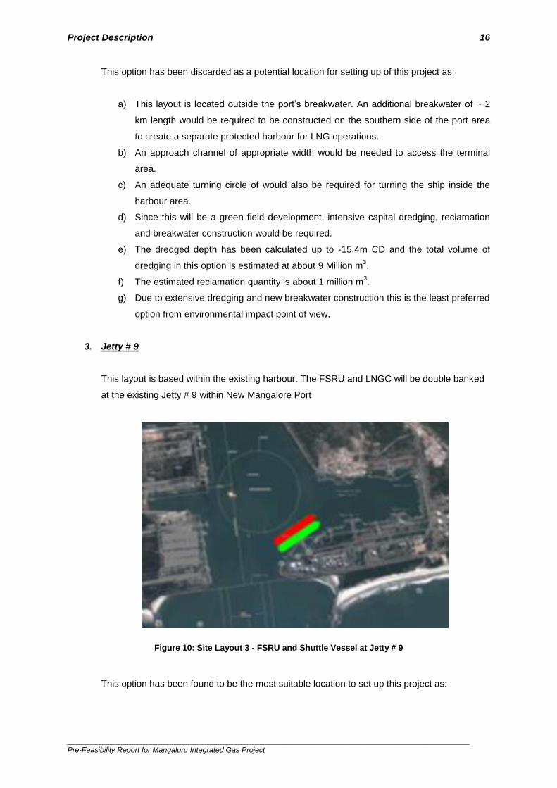
3. Jetty # 9
This layout is based within the existing harbour. The FSRU and LNGC will be double banked
at the existing Jetty # 9 within New Mangalore Port
Figure 10: Site Layout 3 - FSRU and Shuttle Vessel at Jetty # 9
This option has been found to be the most suitable location to set up this project as:
Project Description 17
______________________________________________________________________________________ Pre-Feasibility Report for Mangaluru Integrated Gas Project
a) The Centre to Centre of existing Jetty # 9 and Jetty # 10 is about 390 m thereby
satisfying the minimum safety distance prescribed by OISD Standard 194 for LNG
unloading operations.
b) Jetty # 9 is about 160 m from the turning circle. Therefore even in case of double
banking of the FSRU and the Shuttle Vessel, there will remain sufficient clear
distance between the vessels and the turning circle.
c) The edge of the proposed vessel will be about 140m from the transit channel
d) The available dredged depth in front of jetty no 9 is – 12.5m CD. As a result, no
additional dredging is envisaged for berthing the vessels.
No alternative routes have been considered for the envisaged ~ 15 km R-LNG pipeline as it is
proposed to be laid along the existing elevated pipe rack belonging to MSEZL for which EC has
already been obtained. The laying of HEPL’s R-LNG pipeline on this pipe rack does not envisage any
modifications to the existing structure or any impact to the surrounding environment and ecology.
3.4 Magnitude of Operation HEPL’s proposed project at NMP can essentially be classified as a small scale LNG (SSLNG) project.
It is envisaged that initially, the terminal shall handle 0.5 – 1.5 MMTPA of R-LNG during the first 2
years of operation. The LNG Shuttle Vessels are expected to deliver their cargoes to the FSRU on a
weekly basis. It is also envisaged that additional Natural Gas transmission infrastructure shall develop
during this initial phase thereby increasing the demand for R-LNG. After establishing its operations,
the terminal capacity may then be ramped up to 3.0 MMTPA based on the expansion plans of
industries in the catchment area of the Project.
3.5 Process Schematics
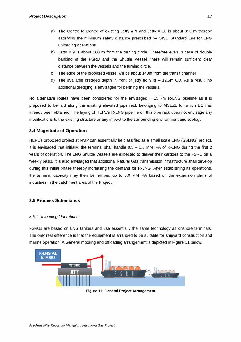
3.5.1 Unloading Operations
FSRUs are based on LNG tankers and use essentially the same technology as onshore terminals.
The only real difference is that the equipment is arranged to be suitable for shipyard construction and
marine operation. A General mooring and offloading arrangement is depicted in Figure 11 below.
Figure 11: General Project Arrangement
R-LNG P/L to MSEZ

Project Description 18
______________________________________________________________________________________ Pre-Feasibility Report for Mangaluru Integrated Gas Project
As the Shuttle Vessel arrives at the port and berths at the jetty or along the FSRU, the LNG transfer
lines as well as vapour return line are connected to the LNGC and the unloading process is initiated.
LNG unloading and transfer to the FSRU is done in a “closed” circle. While the LNG is transferred by
the Shuttle Vessel’s in-tank pumps, the vapours in the FSRU tanks are transferred to the carrier
tanks. The vapour return line balances the pressure across the transferring tanks and avoids vapour
locks or back pressure in the tanks. If the pressure in the tanks cannot be maintained within
acceptable limits, then compressors are used to transfer the vapour, or unloading rates must be
reduced. The LNG receiving process is designed such that it remains independent with respect to the
continuous re-gasification process of the FSRU. The Shuttle Vessels and FSRU expected to berth at
the terminal are expected to have a maximum storage capacity of 50,000 m3.
3.5.2 Jetty
The jetty comprises of an unloading platform of size ~ 66 m x ~ 13 m. A total of 2 breasting dolphins
are assumed to be required for berthing of FSRU or LNG carrier. This maximum size of FSRU and
Shuttle Vessels are assumed to be 50,000m3 each. As the ship range is small, a maximum of four
mooring dolphins are envisaged for mooring the vessels. Marine equipment such as Fenders, quick
release mooring hooks, berthing aid system, environment management system, fire monitors etc. are
assumed to be installed on the jetty.
3.5.3 LNG Re-gasification
The re-gasification process of the FSRU comprises of multiple re-gasification trains which operate in
parallel. Typically these trains are sized with inbuilt redundancy such that they operate in N-working-
1-standby configuration. The FSRU in-tank pumps transfer the LNG stored in the FSRU tanks to the
suction drum, from where the high-pressure booster pumps boost the pressure and feed it to the
vaporizers. The high pressure pumps raise the pressure of the LNG from typically 5 bar g to the
export pressure required by the customer (e.g. typically 50 bar g for a power generation plant or 100
bar g for a gas network). The vaporizers could use sea-water heat to vaporize the LNG into NG. This
high-pressure NG is then metered and dispatched into the shore based NG pipeline via high pressure
NG unloading arm.
There are many methods available to convert re-gasify LNG to R-LNG.
a) OLVs at sea terminals utilize the thermal energy in seawater to vaporize LNG. The primary
environmental question associated with the use of OLV technology is the potential impact of
seawater intakes on marine life.
b) AAVs are used to vaporize LNG into natural gas by using the thermal energy in the ambient
air.

Project Description 19
______________________________________________________________________________________ Pre-Feasibility Report for Mangaluru Integrated Gas Project
Traditionally, base load regasification terminals have used two types of vaporizers:
a) 70% uses the ORV
b) 25% uses the SCV
c) The remaining 5% uses the IFV
An OLV can be selected depending on the availability of clean seawater and an environmentally
suitable location for disposal of the cold water. For an open loop type, the FSRU typically will also
have a supplementary steam based heating facility. If variations in gas dispatch are envisaged,
variable speed booster pumps are considered for matching the variations.
The vaporizing systems currently in use in India are shown in Table 7 below.
Table 7: Vaporizing Systems in Major LNG Terminals in India
LNG Terminal Capacity Vaporising System
RGPPL LNG Terminal, Maharashtra
5 MMTPA Main: Glycol – Water IFV [heating sources are Air (inlet of GTG)]
Petronet LNG, Dahej, Gujarat 10 MMTPA
Main: Glycol – Water IFV [heating sources are Air & GTG exhaust] Backup: SCV [heating source is fired Gas]
ShellHazira Terminal, Hazira, Gujarat
3.6 MMTPA
Main: ORV [heating source is Seawater] Backup: SCV [heating source is fired Gas] Proposed: Glycol – Water IFV [heating sources are Air & GTG exhaust]
Petronet LNG, Kochi, Kerala
5 MMTPA
Main: Glycol – Water IFV [heating sources are Air & GTG exhaust] Backup: SCV [heating source is fired Gas]
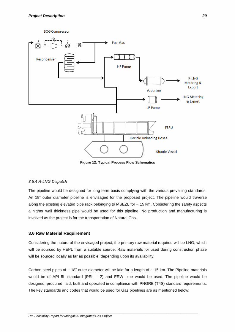
Other facilities such as skid metering system for pipeline regulation shall be included at the jetty.
Figure 12 below depicts the typical process flow of a FSRU based regasification plant.
Project Description 20
______________________________________________________________________________________ Pre-Feasibility Report for Mangaluru Integrated Gas Project
Figure 12: Typical Process Flow Schematics
3.5.4 R-LNG Dispatch The pipeline would be designed for long term basis complying with the various prevailing standards.
An 18” outer diameter pipeline is envisaged for the proposed project. The pipeline would traverse
along the existing elevated pipe rack belonging to MSEZL for ~ 15 km. Considering the safety aspects
a higher wall thickness pipe would be used for this pipeline. No production and manufacturing is
involved as the project is for the transportation of Natural Gas.
3.6 Raw Material Requirement Considering the nature of the envisaged project, the primary raw material required will be LNG, which
will be sourced by HEPL from a suitable source. Raw materials for used during construction phase
will be sourced locally as far as possible, depending upon its availability.
Carbon steel pipes of ~ 18” outer diameter will be laid for a length of ~ 15 km. The Pipeline materials
would be of API 5L standard (PSL – 2) and ERW pipe would be used. The pipeline would be
designed, procured, laid, built and operated in compliance with PNGRB (T4S) standard requirements.
The key standards and codes that would be used for Gas pipelines are as mentioned below:

Project Description 21
______________________________________________________________________________________ Pre-Feasibility Report for Mangaluru Integrated Gas Project
ASME B 31.8
OISD -141
API 5L
3.7 Resource Optimisation HEPL has charted out a comprehensive roadmap, which shall be meticulously followed in order to
obtain the desired project progress. To this regard, HEPL has plans to expand its available resources
(Human, Machinery and Financial) to achieve Resource Optimization. During the construction phase
for the envisaged pipeline, reuse and recycling is envisaged in the following manner:
a) All construction and testing equipment used in the project would be put to use in other similar
project once the proposed pipeline is completed
b) Water used for hydrostatic testing of pipes during commissioning will be stored and and
disposed of properly as per norms
3.8 Availability of Utilities
3.8.1 Water Requirement
The major source of water around the area is Gurupur River and Netravati River. Moreover, the
Mangalore City and industrial area has municipal corporation water supply which lifts water from
pumping station near Thumbe. This project does not envisage use of freshwater for the processes.
Water consumption of ~ 2.5 KL / day is envisaged during construction period and the water would be
sourced through road tankers locally. During operation stage of the FSRU it is envisaged that a
maximum of 50 people will be deployed at the terminal. About 70 litres of water is consumed per
person per day; as such a total of only about 3.5 KLD is being used for domestic consumption.
Remaining water will be used for ship supply and miscellaneous use.
3.8.2 Power Requirement
The power requirement of the proposed FSRU at the Jetty will primarily be met by the BOG generated
out of cargo tanks of the FSRU. Typically, for achieving ~ 1 MMTPA throughput, approximately 2.5 –
3.0 MW power would be required.
Required power for Intermediate Pigging station, Dispatch and receiving Terminal shall be drawn from
the nearly local sources of the respective State Electricity Boards. Power supply shall be taken from 4
pole structure. Emergency power by DG sets, UPS supply for instrumentation, Telecom & SCADA

Project Description 22
______________________________________________________________________________________ Pre-Feasibility Report for Mangaluru Integrated Gas Project
also to be considered at dispatch & receipt stations. Any additional power / energy requirement for the
FSRU operations will be met / arranged locally.
3.9 Waste Management
Quantity of waste generated during pipeline construction would be ~ 0.5 - 1 kg / per capita / day
during construction phase. On completion of construction works, all temporary structures, surplus
materials and wastes would be removed to avoid future land use incompatibility and steps would be
taken to reinstate the land to its near original state.
The development of the FSRU project considers potential impact on the environment, due to:
1. Solid and Liquid Waste Generation
2. Noise Emissions
3. Emissions into the atmosphere
3.9.1 Solid and Liquid Waste Generation
The cargo to be handled at proposed FSRU will be LNG and is only handled / transported through
pipelines. As such, cargo operations are not envisaged to generate solid waste. Use of the facilities at
the berth may however lead to small amounts of solid waste generation. The total solid waste
generated is envisaged to be a maximum of 20 kg/day. Adequate facilities for collection and
conveyance of municipal wastes will be provided.
The solid waste collected from the ships berthing at FSRU terminal will be collected appropriately and
transported by small boats to land side regularly and disposed from the docks to appropriate locations
identified by the local Municipal Corporation in Mangaluru.
The quantity of sewage generation envisaged is very less. Sewage disposal at the FSRU will be
managed through septic tanks (or its equivalent) to be provided at the FSRU terminal. The FSRU will
be provided with a sewage treatment plant meeting the MARPOL requirements. The sewage will
collect:
Grey water;
Black water.
Black water will be treated; sludge content will be held on-board for transfer to shore reception
facilities. Concentration of pollutants and chemicals at the discharge shall not exceed limits indicated
by the “International Convention for the Prevention of Pollution from Ships” (Maritime Pollution –
MARPOL).
Project Description 23
______________________________________________________________________________________ Pre-Feasibility Report for Mangaluru Integrated Gas Project
3.9.2 Noise Emissions
For the proposed FSRU, the main emission sources for Noise include the following:
Sea water process pumps;
Sea water cooling pumps;
Hypochlorite dosing system;
Generation system;
Sanitary discharge pumps;
Booster pumps;
Cooling water unit and Compressors
Diesel Gensets
Gas Gensets / Engines
Fire water Pumps (motor based / Engine based)
Sound pressure levels (at 1 m from the source) can be preliminarily assumed between 75 and 95
dB(A) each. This will be confirmed at a later stage of the project. If necessary, noise reduction
measures will be provided.
3.9.3 Emissions into the Atmosphere
The FSRU operation will involve the following emissions to atmosphere:
a) “Conveyed” emissions due to gas combustion for FSRU power generation;
b) “Conveyed” emissions from unit incinerator;
c) “Fugitive” emissions of Total Organic Compounds (TOC) from FSRU:
d) Joints and valves (due to LNG receiving system),
e) Joints, pumps and compressors (due to LNG regasification and send-out),
f) Joints and oil storage tanks (due to energy production)
During normal operating conditions, the FSRU will be fed by boil-off gas. Exhausts of the combustion
will be represented by NOx and CO emissions. In case dual fuel engines are used, potential
additional emissions of sulphur oxides and particulate might occur. Emissions will be conveyed
through a stack positioned in the aft part of the FSRU. The FSRU unit shall respect emission limits
presented in Annex VI of the “International Convention for the Prevention of Pollution from Ships”
(Maritime Pollution – MARPOL). With reference to nitrogen oxides, MARPOL only presents the
following maximum NOx emission rates at the stack for diesel engines:
14.4 g/kWh when rated engine speed n is less than 130 rpm;
44.0 * n (-0.23) g/kWh when rated engine speed n is 130 or more but less than 2,000 rpm;

Project Description 24
______________________________________________________________________________________ Pre-Feasibility Report for Mangaluru Integrated Gas Project
7.7 g/kWh when rated engine speed n is more than 2,000 rpm.
With reference to Sulphur oxides and particulate matter emissions, MARPOL states that these
emissions on ships will in general be controlled by setting a limit on the Sulphur content of marine fuel
oils as follows. The Sulphur content of any fuel oil used on board shall not exceed the following limits:
4.50% m/m prior to 1 January 2012;
3.50% m/m on and after 1 January 2012;
0.50% m/m on and after 1 January 2020.
Incinerators installed on board a unit after 1st January 2000 shall meet the requirements contained in
Appendix IV of Annex VI of the MARPOL, presented below:
Percentage of CO2 in combustion chamber: 6-12%;
CO in flue gas maximum average: 200 mg/MJ;
Soot number maximum average: Bacharach 3 or Ringelman 1 (20% opacity);
Unburned components in ash residues: maximum 10% by weight;
Combustion chamber flue gas outlet temperature range: 850 - 1,200 °C.
Additional limits that are restrictive might be requested by national and local Authorities during the
permitting phase. With reference to fugitive emissions, on the basis of available information from
similar FSRUs, it is possible to estimate a yearly overall TOC emission equal to 1 ton per year.
Maximum NOx concentration for a new gas turbine having a capacity less than 100 MW is equal to
100 ppm (as per Environmental Protection Rules).
The FSRU shall meet the relevant MARPOL and applicable flag requirements. In detail, the FSRU will
respect environmental limits indicated in the “International Convention for the Prevention of Pollution
from Ships” (MARPOL). MARPOL is one of the most important international marine environmental
conventions. It was designed to minimize pollution of the seas, including dumping, oil and exhaust
pollution. Its stated object is to preserve the marine environment through the complete elimination of
pollution by oil and other harmful substances and the minimization of accidental discharge of such
substances.
The original MARPOL Convention was signed on 17 February 1973, but did not come into force. The
current Convention is a combination of 1973 Convention and the 1978 Protocol. It came into force on
2 October 1983. As of 31 December 2005, 136 countries (including India), representing 98% of the
world's shipping tonnage, are parties to the Convention. Following is an overview on main emission
data associated with the project:

Project Description 25
______________________________________________________________________________________ Pre-Feasibility Report for Mangaluru Integrated Gas Project
3.10 Schematic Representation A schematic representation of the envisaged facilities is given in Figure 13 below.
Figure 13: Schematic Representation of Regasification Process

26
______________________________________________________________________________________ Pre-Feasibility Report for Mangaluru Integrated Gas Project
Chapter 4 Site Analysis
4.1 Connectivity A reconnaissance survey was conducted for the port and the Mangalore Special Economic Zone.
Environmental aspects such as current land use pattern at the project site, activities within the vicinity
of the proposed project site and also within the 10 km radius of the project site have been identified
under the reconnaissance survey.
Location of the project site in Karnataka state is shown in Figure 14 below.
Figure 14: Project Location
The proposed area for the LNG handling facility is located at 5 km North of Mangalore City in Dakshin
Kannada district of Karnataka on west coast. The New Mangalore Port is a deep-water, modern, all-
weather port situated at Panambur, Mangalore, in the Karnataka State of India. The port is located
170 nautical miles South of Mormugao Port and 191 nautical miles North of Cochin Port. The port has
the deepest inner harbour on the West Coast of India. Mangaluru is the largest city and administrative
headquarters of the Dakshina Kannada district. It is the chief port city of the Indian state of Karnataka
and is located around 352 km from the state capital Bengaluru, and situated between the Arabian Sea
and the Western Ghats mountain range. Mangalore Port already host jetties for bulk cargo, cement,
coal, liquid Ammonia and oil berths.
The MSEZL is a notified sector-specific petrochemical SEZ in Mangaluru. The MSEZL operates an ~
15 km direct pipeline-cum-road corridor connecting the MSEZ units to the New Mangalore Port. This
elevated pipe rack is setup to make way for smooth movement of goods between the NMP and the
MSEZ and is aimed at bringing down pressure on public infrastructure.

Site Analysis 27
______________________________________________________________________________________ Pre-Feasibility Report for Mangaluru Integrated Gas Project
The MSEZ is modelled on a cluster approach because of which it had advantages of proximity to the
port and feedstock, shared infrastructure, cost optimisation by leveraging scale, reduced area
requirement, and improved environment management.
The National Highway, NH-66 passes right outside the port. The nearest railway station is Surathkal
(~ 7km), which is on Konkan Railway route. Mangalore International Airport is located in Bajape at a
distance of ~ 12 km from New Mangalore Port.
4.2 Land Form and Ownership The proposed project site is at Jetty # 9 located inside New Mangalore Port. This is an existing jetty
having all mooring and bollard facilities. Other than a berthing facility at Jetty # 9, no other land /
space requirement has been envisaged by HEPL for this Project.
Figure 15: Area within 10 km Radius of Project Site
A Google map image depicting the 10 km radius of the project site is presented in Figure 15 above.
The proposed pipeline associated with the project shall be laid along MSEZL’s existing elevated
MSEZ

Site Analysis 28
______________________________________________________________________________________ Pre-Feasibility Report for Mangaluru Integrated Gas Project
pipeline corridor. Environmental Clearances for this pipe rack have already been obtained. The
proposed pipeline shall traverse along the pipe rack in the following manner:
Table 8: Route of Proposed Pipeline
Corridor Section Extent Distance RoU
Within NMP Jetty # 9 up to NMP Silver Gate (Gate # 2)
~ 1.55 km On existing sleepers within NMP
Reach – I NMP Silver Gate up to NH Crossing
~ 1.6 km On elevated pipe rack
NH Over Bridge NH Crossing ~ 0.14 km On elevated pipe rack
Reach – II Parallel to Gurupura River
~ 1.7 km On elevated pipe rack
Reach – III Parallel to Total Gas Terminal
~ 1.9 km On elevated pipe rack
Reach – IV Up to MSEZ ~ 6.55 km On existing sleepers
4.3 Topography
The environmentally critical habitants and conditions related to the project are presented in, Table 8
below.
Table 9: Conditions at location of the proposed LNG jetties in the sea
Sl.No. Parameters Status
1 Corals and ecologically sensitive areas at proposed Jetty site Not Applicable
2 Whether located in nesting and breeding site Not Applicable
3 Any mangroves or sand dunes present at proposed Jetty site Not Applicable
The proposed location of the envisaged Project is shown in the Topographic Map depicted by Figure
16 below.
Figure 16: Topography Sheet

Site Analysis 29
______________________________________________________________________________________ Pre-Feasibility Report for Mangaluru Integrated Gas Project
Recent Site Photographs and satellite imagery of vicinity map showing the area within 5 km radius of
the project site is shown in Figure 17 and Figure 18 respectively.
New Mangalore Port
Panambur Beach Near New Mangalore Port
New Mangalore Port Main Gate
HT Lines Near New Mangalore Port
Storage Tanks belonging to MCFL
National Highway Outside the Port

Site Analysis 30
______________________________________________________________________________________ Pre-Feasibility Report for Mangaluru Integrated Gas Project
MSEZL Elevated Pipe Rack NH Crossing
MSEZL Elevated Pipe Rack
Figure 17: Recent Site Photographs
4.4 Existing Land Use Pattern The process site falls completely within New Mangalore Port and is under the jurisdiction of NMPT.
Major land use patterns of study area covers industrial area, human settlements, agricultural land and
water bodies.
Table 10: Existing Land Use Pattern
Sr. No. Parameters Status
1 Type of land use, any settlements Barren land, no settlements on
proposed site
2 Plantation Sparse vegetation of Zizipus zuzuba
and Azadiracta Indica
3 Sensitive or endangered species
found Not Applicable
4 Any village roads or other access
roads passing None at site, but surrounded by NMPT
road
5 Any transmission lines or pipelines None at site, but HT lines present 200
m away in southeast direction
6 Any water bodies and streams are
flowing Gurupur River flowing 150 m away from Jetty 9 in southeast direction
7 Any solid waste dump sites located Not Applicable
8 Whether the project site was used as
industrial application earlier None at site, but the site is surrounded
by other industries
10 Forest land Not Applicable
11 Crop land None at site, but coconut and paddy
fields are present 400 m away towards the east
12 Any canal passing through site Not Applicable

Site Analysis 31
______________________________________________________________________________________ Pre-Feasibility Report for Mangaluru Integrated Gas Project
The pipeline originating at Jetty # 9 within New Mangalore Port shall traverse on the existing elevated
pipe rack belonging to MSEZL. A ~ 1.7 km section of this pipe rack passes parallel to the Gurupur
River. EC for this pipe rack has already been granted by MoEF&CC.
Bajpe village has a petroleum refinery complex by the MRPL, which is the largest refinery complex in
the Karnataka State. Near the MRPL refinery complex, there are other industries like a OMPL (ONGC
Mangalore Petrochemicals Limited), HPCL and Petronet MHB Ltd. MCFL (Mangalore Chemicals and
Fertilizers Ltd.) is in close vicinity of New Mangalore Port.
Mangalore City is the largest settlement in vicinity of project site. Other prominent settlements are
Thokur, Baikampady, Bondel, Bajala, Suratkhal and Ullal. The project site is free of any settlement
and no roads, tracks or transmission lines pass through site. However, Kudremukh Iron Ore plant is
situated in the Mangalore port premises. The site does not have any perennial water body or stream.
However, River Gurupur flows in close proximity in southeast direction.
4.5 Existing Infrastructure
The proposed site at Jetty # 9 is an existing Jetty with a berth length of 330m and available draft of
10.5m with a maximum allowable deadweight of 45,000 MT. They Jetty has existing Power systems,
Instrument/plant air system, Fire, Gas & Spill system, Fire water system etc. These systems are
proposed to be upgraded (if necessary) for the successful commissioning of the envisaged Project.
The Jetty is currently handling LPG, Edible Oil and POLs. LPG is unloaded from vessels using
unloading arms and associated pipelines installed on the Jetty. It is proposed that if LNG handling
facility is created at Jetty # 9, then these pipelines may be replaced with R-LNG and LNG unloading
arms and associated facilities such as metering stations, pressure reduction station and emergency
shut off valves. The R-LNG pipeline shall pass on the existing elevated pipe rack for ~ 15 km from the
Silver Gate of NMP up to the MSEZ.
4.6 Soil Classification The soil in the district is mostly lateritic type and is found distributed in the Pediplain area. The soil is
characterized by high iron and aluminium content. Lateritic soil is mostly red in color and yellow
loamy, pale to bright red colours are also seen. Lateritic soil is suitable for Paddy, Sugarcane,
Arecanut and Plantation crops, viz. crops like Cardamom & plantains. Loamy red soils are distributed
in the lower reaches of valleys. Red lateritic soil is the most dominant soil type in the area.
The texture of the soil varies from fine to coarse. The soil in valleys and intermediate slopes is rich in
loam whereas in upper slopes it is much coarse in nature. The soil responds well to irrigation and
other soil - management practices. Silty and loamy soils are of transported origin and are found
mostly along river banks and in valley plains. They have good infiltration capacity and are well-suited

Site Analysis 32
______________________________________________________________________________________ Pre-Feasibility Report for Mangaluru Integrated Gas Project
for agriculture due to their fertility. The soil characterization in Karnataka State is shown in Figure 17
below.
Figure 18: Soil Characterisation in Karnataka State
4.7 Climatic Data from Secondary Sources
4.7.1 Draft Availability at Site
Jetty # 9 has an available water draft level of 10.5 m and a mean dredged depth of 12.9 m in front of
the jetty. This will be sufficient to bring in a ~ 50,000 cu. m. FSRU and Shuttle Vessel of ~ 50,000 cu.
m. capacity for the project.
4.7.2 Climatic Condition
The climate of the region is tropical and is characterized by the annually recurring seasons of South
West monsoon, post monsoon winter and summer. The main season with their principal
characteristics are as follows:
The cool season (December to March), when winds are NE and the weather is dry with little
cold except in the southern area.

Site Analysis 33
______________________________________________________________________________________ Pre-Feasibility Report for Mangaluru Integrated Gas Project
The hot season (April to May), winds are light and variable with sea breezes on the land.
Tropical cyclonic storms (cyclones) may cross the Arabian Sea in this season.
The SW monsoon or rainy season (June to September). The wind over the sea is between
SW and W, but mainly W to NW along the coast.
The interim period (October and November) is marked by light winds with land and sea
breezes. Occasional tropical cyclones occur in the Arabian Sea in this period.
In much of the Mangalore area, most rainfall occurs during the SW monsoon. While the average
frequency of cyclonic storms in the Arabian Sea is about one per year, there have been years in
which two or three cyclones have occurred and also periods of one or two years without one, based
on the meteorological records of the past 30 years.
4.7.3 Rainfall
Table 10 below depicts the average Rainfall conditions at Mangaluru
Table 11: Rainfall in Mangaluru
Description Detail
Average Rain Fall per year 3467 mm
Maximum Rain Fall 1102.7 mm/month 270 mm/day
Average number of rainy days
122.7 days
4.7.4 Wind Data
Climatological Tables of Observatories in India (1951-1980), published by the India Meteorological
Department, were used to obtain historical data for the region (Annexure 3).Mangalore (Panambur) is
the nearest meteorological observatory to the project site established in the year 1953. Temperature
varied in the range of 20.7 0C to 33.9 0C. The average annual rainfall is 3965.4 mm. The annual
average of number rainy days in a year is 120.5.
The annual average wind speed is 6.7 km/h. The wind directions are predominantly from South West,
West and North West directions during monsoon season. During non-monsoon season, wind
directions are from North, North East and East during daytime and from South West, West and North
West during night time. The annual windrose diagram for the Mangalore (Panambur) area is
presented in Figure 18 below.

Site Analysis 34
______________________________________________________________________________________ Pre-Feasibility Report for Mangaluru Integrated Gas Project
Figure 19: Annual Windrose Diagram
The winds in the monsoon months of June, July and August are predominantly from SW to W with a
maximum intensity of 2.1 – 3.6 m/s. The winds in the remaining months of the year are predominantly
from NW and the maximum intensity during this period is also 2.1 – 3.6 m/s. The maximum wind
speed so far recorded has not exceeded 62 km per hour (16.9 m/s), except once during a storm in
1965 when the maximum speed recorded was 97 km per hour (26.9 m/s).
Table 12: Wind Data for Mangaluru
Description Detail
Predominant wind speed along with its Direction
8.4 km/hour, NW
100 years maximum wind speed
97 km/hour
4.7.5 Wave
In general, waves are predominately from west (W) and south-southwest (SSW) at NMP. Occurrence
of 0 – 1m wave height is around 65%, 1 – 2m wave height is around 16% and 2 – 3m of wave height
occurs around 17% of the time.

Site Analysis 35
______________________________________________________________________________________ Pre-Feasibility Report for Mangaluru Integrated Gas Project
4.7.6 Current
The current along the coast during the SW monsoon (from February to September) is generally
towards the South (from 160° to 200°) with a velocity of 0.22 to 0.80 knots. During the NE monsoon
(from November to January), the current is generally towards the North (from 0° to 40° and 320° to
360° bearing) with a velocity of 0.22 to 0.60 knots. In the Port entrance channel protected by
breakwater, the current direction lags 6° to 8° behind the coastal current. The current in the lagoon
area further lags behind the approach channel on an average by 10° to 15°. The magnitude of the
current outside the lagoon area during the monsoon as experienced by pilots is about 1 to 1.5 knots.
4.7.7 Sea Surface Temperature
Seawater temperature varies from 30.9˚C offshore to 30.7˚C towards the coast.
4.7.8 pH
The range of variation in pH of water in the estuary is generally between 7.69 and 7.83 during the
year.
4.7.9 Salinity
The surface salinity measured off Mangalore exhibited a variation from 34.92 PSU to 36.42 PSU.
4.8 Social Infrastructure Available The proposed area for the LNG terminal is located in New Mangalore Port, Mangalore, Dakshina
Kannada, Karnataka. Although the proposed project doesn’t displace any human settlement, for the
purpose of the establishing the background socioeconomic conditions of the study area, the human
settlements that are falling within the buffer zone of 10 km radius from the project site have been
considered for mapping the socioeconomic aspects. The study area falls in the district of Dakshina
Kannada, which is bordered by Udupi District to the North, Chikkamagaluru district to the northeast,
Hassan District to the east, Kodagu to the southeast, and Kasaragod District in Kerala to the south.
Mangalore is the headquarters of the district. According to the Census Directory 2001, the study area
is includes three urban agglomeration namely Mangalore (M Corp.), Mangalore (M Corp+OG) and
Bajpe (CT).
The New Mangalore Port is India's ninth largest port and chief port of Karnataka. Mangalore's port
handles 75 per cent of India's coffee exports and the bulk of the nation's cashew export.Some of the
major industrial players are Mangalore Chemicals and Fertilizers Ltd. (MCF), Kudremukh Iron Ore
Company Ltd. (KIOCL), Mangalore Refinery and Petrochemicals Ltd. (MRPL), BASF, Bharati
Site Analysis 36
______________________________________________________________________________________ Pre-Feasibility Report for Mangaluru Integrated Gas Project
Shipyard Limited, Total Oil India Limited (ELF Gas), etc. Mangalore’s economy is dominated by the
agricultural processing and port-related activities and the Mangalore is seen as the next destination of
IT and IT Enabled Services (ITES) companies.
Dakshina Kannada district is the largest producer of Marine Fish in the state. The Volume of fish
catch in the district during the year 2011-12 was about 138506.84 tons. And the district holds the
number of infrastructure facilities supporting fishing industry. There are about 60 ice plants having a
capacity of 1020 metric tons per day and 11 Cold storage facilities holding capacity of 387 metric tons
per day. With respect to the fishermen population involved in fishing were 2458 full time fishermen
and 1409 part time fishermen.
According to Census 2001, the total population involved in employment is about 42% which is less
than the districts rate of 50%. And only about 1.25% of the total working population is involved in
Agricultural activities. 14.97% of the total working population is involved in ‘Household Industries’ and
83.78% of the working population is involved in ‘Other Industries’.
With respect to the medical facilities, Mangalore holds number of health care facilities which includes
number of Government Hospitals and Private clinics. The major Government hospitals in the city are
Lady Goshen Hospital Govt. Maternity hospital, Wenlock Govt. Hospital Hampankatta, ESI
Dispensary Govt. hospital and Rural Matenity and Child Welfare Centre. And major private clinics
were City Hospital Kadri, Chethan Hospital, G.V.Pai Memorial Hospital and Highland Hospital
Highlands. The health Indicators such as the institutional birth rates are 96% which is higher than the
Karnataka state level of 65.1%. 89.5% of the district population have availed full immunization
program, which is less than that of state’s level of 76.7%. In district nearly 88.4% of people have
access to toilet facilities.
Major drinking water facility in the study area was through public distribution system by Mangalore
City Corporation. About 81.61% of the total populations in the study area are literates. In district
85.6% of the children (aged 7plus) are literate and 100% of the girl children (aged 6 to 11) attend
school. Major education facilities are available within the study area. The medium of instruction in the
schools were Tamil and Kannada in schools and English in the colleges. There are number of
Government schools are present in the study area and in addition to these number of private run
schools such as Holy Angels Higher Primary School, Sacred Heart High, St Lawrence Higher Primary
School, Besant National Girls High School, Sri Ramakrishna High School, Anandashram High School,
St Agnes Girls High School, etc. he city is well connected with public transport facilities.

37
______________________________________________________________________________________ Pre-Feasibility Report for Mangaluru Integrated Gas Project
Chapter 5 Planning Brief
5.1 Planning Concept
HEPL, through this proposed project, intends to supply Re-gasified LNG to various Industries in the
Mangalore through an R-LNG Pipeline. These industries include, but are not limited to Fertilizers
sector, Petrochemicals and CGDs. Site has already been identified as Jetty # 9 inside the NMP for
stationing the FSRU and Shuttle Vessel. The proposed evacuation pipeline shall be using the existing
elevated pipe rack belonging to MSEZL.
The Project Influence Area is determined as an area within 10 km radius from project location at Jetty
# 9 within NMP and has been earmarked for EIA&RA studies. The site for proposed development of
the FSRU based LNG handling facility falls within notified Port Limits of NMP. The FSRU will be
located at latitude 12°55'23.5"N & 74°48'31"E at NMP, Mangaluru, Karnataka State. The core area of
5.0 km radius falls predominantly within the sea water spread area. Land area falling within 5 km
radius is about 50% The Google image of the Core Project Influence Area is shown in Figure 19
below.
Figure 20: Core Project Influence Area (5km Radius)

Planning Brief 38
______________________________________________________________________________________ Pre-Feasibility Report for Mangaluru Integrated Gas Project
As a result, Baseline data generation for EIA study covering One (01) non monsoon season is
proposed to be carried out as per the following plan:
a) Marine Environment:
The baseline Marine environmental surveys near coastal / offshore areas of the project site
shall be carried out through field surveys by covering 5 km radius towards seaside. One time
sampling for marine environmental surveys shall be carried out during the period of June
2018 (prior to onset of monsoon).
b) Terrestrial Environment:
The core area of 5 km radius of the proposed project falls predominantly in marine waters. As
such, this study can ideally be considered as a Marine EIA Study. Accordingly, limited primary
data collection for terrestrial components has been proposed for this study and available /
appropriate secondary data shall be collected, reviewed and presented in this study. Existing /
valid secondary data available at New Mangalore Port shall be collected to study / understand
the baseline environmental conditions at the project location.
c) Ecology:
Primary survey to understand the ecology (Flora and Fauna) of the project area shall be
carried out as part of this EIA study.
The Project components have also been clearly identified, and their requirements in lieu of the
timelines have also been fixed. The Project Schedule shall be prepared keeping in mind various
factors like timelines for completion of project, project milestones etc. HEPL also has a system in
place for slippage monitoring. Slippages shall be meticulously monitored and suitable corrective
actions shall be performed by HEPL ensuring that the project timelines are being strictly adhered to.
5.2 Population Projection Cumulative population in the study area is ~ 8,23,860 which is about 43.41% of the district’s
population with ~ 4,13,569 males and ~ 4,10,291 females. The population of children below 6 years
was found to be 84,003 which are of about 10.19% of the total population in the study area.
Population density is 3,586.5 per sq. km. as compared to district’s 390. The decadal population
growth rate of the district was about 9.8 % (2001-2011). The sex ratio was found at 992 females per
thousand males, with that of district’s ratio of 1022 and the children sex ratio was about 960.
Vulnerable population generally indicates population of Scheduled Caste (SC) and Scheduled Tribes
(ST) Largest Scheduled Castes found in the district were Moger, Holaya and Adi Dravida while largest
STs were Marati, Naikda and Malaikudi. The rate of SC and ST population in the study area was

Planning Brief 39
______________________________________________________________________________________ Pre-Feasibility Report for Mangaluru Integrated Gas Project
about 4.06% and 0.9% when the same was compared with the district it was 6.91% and 3.31%
respectively. Tulu, Konkani, Kannada, Beary Bashe are the common languages spoken.
5.3 Land Use Planning
The proposed project site is at Jetty # 9 located inside New Mangalore Port. This is an existing jetty
having all mooring and bollard facilities. Other than a berthing facility at Jetty # 9, no other land /
space requirement has been envisaged within the Port by HEPL for this Project. A small land parcel
suitable for Terminal Station for the proposed pipeline shall be sought directly from the customers
within MSEZ.
5.4 Assessment of Infrastructure Demand
A detailed assessment of infrastructure demand shall be prepared during the FEED stage. The
minimum infrastructure required has been assessed and has been explained in the Project
Description section of this report.
5.5 Amenities / Facilities
HEPL intends to set up a fully-fledged and independent Floating LNG Storage and regasification
terminal at NMP along with an R-LNG evacuation pipeline directly connecting customers. On the
FSRU, in order to face operative conditions, a number of people shall be housed on board the vessel
as per the DG Shipping guidelines, inclusive of technical personnel dedicated to typical terminal
operations (actual value will be defined in the later stage of the project).
Based on the actual number of people, accommodations may include the following:
1. Public spaces:
Officers' dining room, officers' lounge, crew mess, crew lounge, duty mess,
hospital/dispensary, gymnasium
2. Service spaces:
Galley, officer and crew pantries, pantry at cargo control room, officer, FSRU and crew
laundries, storage lockers, linen (clean, dirty) lockers, incinerator room, waste handling room;
3. Sanitary spaces:
Public toilets, officer and crew changing rooms;
4. Operational spaces:
Combined wheelhouse with chart and radio room, engine control room, cargo control room
with related meeting room, conference room, main administration office, one (1) office each
Planning Brief 40
______________________________________________________________________________________ Pre-Feasibility Report for Mangaluru Integrated Gas Project
for Captain, C/Engineer and Senior Officers, document store, central fire control station, fire
equipment rooms;
5. Provisions stores:
Dry provision (18°C), meat (-25 °C), fish (-25°C), vegetable (2°C), lobby (4°C), bonded store.

41
______________________________________________________________________________________ Pre-Feasibility Report for Mangaluru Integrated Gas Project
Chapter 6 Proposed Infrastructure
6.1 Industrial Area
The proposed area of operations is the existing Jetty # 9 currently handling LPG and POL products.
Before commencement of the project, HEPL shall suitable modify the existing equipment on the jetty
for handling LNG product. Once the jetty modification is completed, HEPL shall also lay an R-LNG
pipeline from Jetty # 9 to MSEZ in order to supply gas to its customers.
6.2 Residential Area
The FSRU will have experienced crew on board (as per DGS Manning requirements).
Accommodation for the crew shall be provided on board the FSRU during the operational period. As
the area of project activities is within the limits of NMP, no other residential areas are affected by this
project.
6.3 Green Belt
Currently no on land facilities are envisaged for the development of green belt around the facility area.
Development will be finalized based on CCoE approval of layout and considering the safety aspects &
PESO regulations.
6.4 Social Infrastructure
The prime concern for a developing country like India is power security which is presently deficient in
supply in comparison to the demand. To cater to the growing demand- supply gap of gases, import of
LNG is the most viable option. Supply of cleaner fuel will help in reducing environmental pollution
impacts on a long term basis. This objective can be achieved by setting up an LNG FSRU which will
also supplement energy security needs of the state / country. India has already established a few
LNG import and re-gasification terminals which are operating successfully. The share of natural gas in
the overall energy sector in the country will continue to increase.
Apart from fulfilling the immediate need of cleaner fuel (supplement) for power generation, the LNG
supply will also contribute indirectly to food security of the region, state / nation through enhancing
fertilizer manufacture with a cleaner feed stock.
The proposed development is a channel through which LNG handling will take place at NMP. This will
help indirectly to promote opportunities for further industrial growth in the region. It will indirectly assist

Proposed Infrastructure 42
______________________________________________________________________________________ Pre-Feasibility Report for Mangaluru Integrated Gas Project
in the creation more employment to the local population. This is in turn will lead to employment
generation and meeting the occupational requirements of the local population.
As per its Corporate Social Responsibility plan, HEPL shall undertake necessary interactions to
understand the community infrastructure needs of the area and shall thereafter finalise its social
infrastructure development plan.
The project will have overall positive impact on the socio-economic conditions of the region.
Handling/transfer operations of LNG will lead to additional employment opportunities and avenues for
income generation. Proposed development will also create several indirect employment opportunities.
People will have higher earning and buying capacities and their standard of living will increase.
The quality of life in the region is likely to improve due to the creation of limited direct but more indirect
jobs for the local people. This will result in more than one earning member in the family and reduce
the dependency on a single earner and enable them with better economic freedom.
HEPL, as a responsible corporate citizen will support either directly or through the district
administration – development of social infrastructure for the local communities. The impact of the
support will be reviewed periodically, monitored, and assessed.
The existing Social Infrastructure in Mangaluru has been described in Section 4.8 of this report.
6.5 Connectivity
The identified project site at Jetty # 9 inside New Mangalore Port, lies in the Panambur, Dakshina
Kannada district of Karnataka and is well connected to the nearest Industrial hubs through roads and
railways.
The site is very well connected to National Highway 17 (Approximately at 1.5 km) and Mumbai –
Mangalore Railway Line. Nearest railway station is Surathkal which is 7 km towards Northeast
direction. Private railway line of NMPT is situated at1.6km towards North direction of project site.
6.6 Drinking Water Management
The project is located in Southern region of Karnataka which is known for heavy rainfall. The annual
rainfall in the Mangalore region is 3965.4 mm with 120.5 rainy days (Climatological Tables 1951 –
1980 published by Indian Meteorological Department attached as Annexure 3).Mangalore lies on the
backwaters of the Netravati and Gurupur rivers. These rivers effectively encircle Mangalore city, with
the River Gurupur flowing around the north and the Netravti flowing around the south of the city.

Proposed Infrastructure 43
______________________________________________________________________________________ Pre-Feasibility Report for Mangaluru Integrated Gas Project
The rivers form an estuary at ullal in the south-western region of the city and subsequently flow into
the Arabian Sea. The coastline of the city is dotted with several beaches, such
as Mukka, Panambur, Tannirbavi, Suratkal, and Someshwara. Major source of drinking water of
Mangalore City is Thumbe dam located in upstream region of Netravati River.
The industrial area has municipal corporation water supply which lifts water from pumping station near
Thumbe. Most of the villages have public dug wells and hand pumps.
The FSRU has inbuilt provision for drinking water management system. HEPL will ensure the supply
of drinking water for the crew from a nearby source / facility at the site.
6.7 Fire Water Storage System Management
Main components of fire water system include fire water storage, fire water pumps and firewater spray
system (deluge). FSRU has inbuilt fire detection, fire protection and firefighting facilities onboard.
In order to detect any leakage and anticipate potential fire, a fire and gas detection system will be
provided to cover the facility.
The fire and gas detection system will be connected to the ESD system and will activate both visible /
audible alarms and initiate the required activities, including isolation of inventories.
Furthermore, the FSRU will be provided with active means of fire fighting including deluge system and
hydrant system. According to applicable codes, all hydrocarbon containing vessels on board the
floating terminal will be protected with a suitable fire fighting system to provide cool-down effect in
case of fire at nearby equipment(s). Moreover, the following items will be protected (IGC Code):
Exposed cargo tank parts;
Cargo manifolds;
Manned structures;
Cargo compressors;
Pump room;
A fire fighting system will be provided on the FSRU to allow fire-fighting using seawater.
6.8 Sewerage System
The FSRU will have a sewage treatment system to treat and discharge waste and meet the MARPOL
standards.

Proposed Infrastructure 44
______________________________________________________________________________________ Pre-Feasibility Report for Mangaluru Integrated Gas Project
Construction activities like civil works that require water for curing of cement concrete and cement
plasters, washing of construction equipment would generate wastewater. The quantity of wastewater
generated would be negligible and hence the expected impact would also be negligible.
Around 70 to 100 persons will be employed for construction activity. Sewage generated by work force
will be treated in septic tank and soak-away pits. Hence there would be negligible impact on water
environment.
6.9 Industrial & Solid Waste Management
Various kinds of solid and industrial wastes that will be generated at the FSRU, will be either safely
incinerated or safely brought to site location and disposed in onshore waste facilities available at site.
Food wastes generated on board the vessel where all plastic materials have been removed will be
ground to a particle size capable of passing through a screen with openings of 25mm and then
discharged.
Construction activities involve Pre-Cast Concrete, Construction Materials Storage & Handling,
Welding, Painting, Fabrication, Labour movement and are expected to generate the following wastes:
a) Rejected concrete due to poor workmanship
b) Hydrated Cements or clinkered cements
c) Left-off welding buds
d) Metal scraps/burrs
e) Contaminated soil due to spillage of chemicals
f) Soil contaminated with welding dust
g) Rejected paints and thinner sludge
h) Empty paint drums and chemical containers
i) Used oil generated from construction equipment and machineries
j) Used batteries
k) Canteen waste
l) Packaging material
6.10 Power Requirement & Supply / Source
Power requirements of FSRU and the facilities at terminal will be met by the boil off gas generated out
of cargo tanks of the FSRU. Any power requirements during construction phase shall be met by
connection from nearest power grid. Power required for pipeline operations shall also be sourced from
the nearest power grid.

45
______________________________________________________________________________________ Pre-Feasibility Report for Mangaluru Integrated Gas Project
Chapter 7 Rehabilitation and Resettlement Plan (R & R) Plan The proposed project had considered many options, of which the location chosen to berth the FSRU
and Shuttle Vessel is Jetty # 9, located within New Mangalore Port. Opposition from the local people
to this project is not expected to be significant as the project location is within the Port territory and is
beyond the limits of the existing fishing harbour entrance. The fishermen hamlets are located at a
distance of 1.5 km. The proposed pipeline traverses entirely on the existing elevated pipe rack
belonging to MSEZ. No displacement of people and homestead is envisaged as a part of this project.
Hence, the Rehabilitation and Resettlement policy will not be attracted under the National
Rehabilitation and Resettlement Policy 2007.

46
______________________________________________________________________________________ Pre-Feasibility Report for Mangaluru Integrated Gas Project
Chapter 8 Project Schedule and Cost Estimates
8.1 Schedule
Project Schedule for commissioning the project is majorly divided in to following milestones as
follows:
1. Conduct major studies and surveys
2. Required clearances and permissions for the site and the project
3. Chartering / conversion of FSRU / LNGC
4. Agreement with MSEZ for use of its Pipeline Corridor for the proposed R-LNG pipeline
5. FEED and Detailed engineering for Jetty Refurbishment and R-LNG Pipeline
6. Procurement of long lead items and other materials
7. Refurbishment of Jetty # 9 and Construction of R-LNG pipeline including civil works,
electrical, mechanical, instrumentation, control room, SCADA, communication and customer
installation readiness
8. Pre-commissioning of project facilities
9. Commissioning of the project
The project can consider two options for the proposed FSRU to produce Natural Gas at the rate of 3
MTPA.
a) Chartering and operating the FSRU by third party
b) Custom building new FSRU
Chartering option reduces the time line by at least 5 years as the custom design, building the hull and
topsides may take considerable time. However, this option may have the flexibility of operating the
FSRU at different gas requirements.
Considering all the above activities, project shall be implemented within shortest possible time once
all the permissions and clearance from state and central statutory bodies are obtained. It is estimated
that from the start of construction work it will take 24 months to commission the project. Project is
expected to be commissioned by 2020.
8.2 Project Cost
The preliminary cost estimate is based on the following assumptions:

Project Schedule and Cost Estimates 47
______________________________________________________________________________________ Pre-Feasibility Report for Mangaluru Integrated Gas Project
a) The cost estimate is approximate based on preliminary sizing of berth and shall be subjected
to a variation of ±20%
b) Unit rates for concrete, steel and pipeline installation is taken from in-house data of previous
projects.
c) Cost of fenders and bollards is taken from previous projects.
d) Cost escalation due to price increase is not included in this estimate
The estimation is divided in following groups:
a) Berth Structure
b) Civil and outfitting works
c) Mechanical Piping and Equipment
d) Engineering and Management
The estimated cost does not account for FSRU chartering. Estimated cost of the project is
summarised in Table 12 below:
Table 13: Project Cost Estimate
S. No. Component Unit Total
(INR Crore)
A Preliminaries
Survey / Studies Lumpsum 5.00
B Berth Facilities
Jetty Strengthening Lumpsum 25.00
Mooring Dolphins Upgrade 30.00
Breasting Dolphins Upgrade 30.00
Fender Upgrades 10.00
Navigational Aids and Shore
approach facility 10.00
C Mechanical and
Electrical Facilities
Mechanical / Equipment Lumpsum 40.00
Fire Fighting facilities Lumpsum 55.00
Piping (Material Supply and
Installation) Lumpsum
25.00
Pipeline Construction Lumpsum 25.00
Cables and installation Lumpsum 15.00
Supports and Installation Lumpsum 20.00
D Miscellaneous
Engineering & management 25.00
Contingencies 25.00
E Total Project Cost
(Inclusive of IDC and Contingencies)
340

48
______________________________________________________________________________________ Pre-Feasibility Report for Mangaluru Integrated Gas Project
Chapter 9 Analysis of Proposal
New Mangalore port is an existing port without any ecologically critical habitants in the vicinity. As per
this preliminary environmental study, there are no environmental regulations that prohibit the
envisaged activities associated with this project. It is proposed that a detailed EIA study would be
carried out in order to obtain environmental clearance.
The benefit to reduction of existing pollution with a clean fuel needs to be highlighted. However, the
existing pollution levels in NMPT are a source of concern. Compliance to the pollution control board
recent recommendations will be a key factor in environmental clearance. As per Ministry of
Environment and forests, Govt of India vide office Memorandum No.J11013/52010-1 A.II (I) dated
13.01.2010 the Baikampady Industrial Cluster, Mangalore in Karnataka State was declared as a
critically polluted area with a CEPI(Critically Environmental Pollution Index) score of 73.68.
Subsequently Karnataka State Pollution Control Board has prepared an Action Plan and submitted to
MoEF&CC for lifting Moratorium of the Balkampady Industrial Cluster. MoEF lifted the moratorium
vide their Memorandum No. J11013/52010-1 A.II (I) dated 23rd May 2011 for Baikampady Industrial
Area. In the action plan submitted by KSPCB, New Mangalore Port Trust has submitted an action
plan as short term measures to mitigate water and air pollution and committed to achieve in the
stipulate date along with the budget. Two years have been completed after lifting of moratorium by
MoEF&CC. Therefore, it is assumed that the action plan is being implemented satisfactorily by all
industries and regularly monitored been monitored by KSPCB.
The proposed marine facilities, re-gasification facilities, evacuation facilities and other supporting
facilities been reviewed for establishing the environmental aspects. Multiple options have been
considered for siting the LNG berth in this Pre-Feasibility Report. All locations lie within the same
region and thus the major environmental issues of the region will apply to all options, with similar
emissions, wastewater discharge and environmental impacts.
However, each of these options also has some distinct characteristics. These are summarized below:
a) Location 1: Lee side of the Southern Breakwater
b) Location 2: Outer Harbour, South of the Southern Breakwater
c) Location 3: Existing Jetty # 9
Location 1 requires extension of the existing breakwater and Location 2 requires the construction of a
new breakwater and a harbour just outside the existing port which is considered to have a significant
environmental impact. This may result in significant concern on shoreline changes and capital dredge
spoil disposal.

Analysis of Proposal 49
______________________________________________________________________________________ Pre-Feasibility Report for Mangaluru Integrated Gas Project
Maintenance dredging at New Mangalore Port is presently approximately 6 - 7 Mm3 per annum.
Location 3 is unlikely to increase maintenance dredging significantly, while Location 1 and 2 are likely
to increase maintenance dredging quantities relative to the existing quantities. While the quantity
needs to be established through detailed modelling, any increase will require a thorough study for
disposal of dredge spoils.
After consideration of all the above factors, Location 1 and 2 will have the largest environmental
impact due to the construction of breakwaters, capital and maintenance dredging and potential for
shoreline change. Based on the highest environment impact, it is recommended that Location 1 and 2
should be excluded from the further assessment.
On the basis of the Location 3 being well within the port with minimal interference to existing users
external to the port, lower maintenance dredging requirement, better wave tranquillity and separation
from existing activities, it is found that Jetty # 9 is considered for implementation of this project.
As part of the proposed project development, following employment and goods/service sourcing
requirements can be locally met:
Unskilled / semi-skilled workers required as part of construction of onshore pipeline – for short
term
Land transport and local accommodation requirements for both construction and operational
personnel
Security and patrolling requirements during operation of terminal and onshore pipeline
Health, Safety, and Environment and Community
The Project development will give highest consideration to the preservation of human life, the
minimization of environmental impacts and the mitigation of adverse effects on community. The main
risk for safety and environment are related to the handling of liquefied natural gas (LNG) and
pressurized natural gas (NG).
LNG is natural gas that has been refrigerated into a cryogenic liquid so that it can be shipped long
distances in dedicated carriers. Once an LNG carrier reaches a receiving terminal, the LNG is
unloaded and stored in FSRU until it is regasified and has been sent to customers through an R-LNG
pipeline. LNG is a hazardous liquid, because of its cryogenic properties and combustibility (as natural
gas). LNG hazards result from three of its properties: cryogenic temperatures, dispersion
characteristics, and flammability characteristics. The extremely cold LNG (about -163°C) can directly
cause injury or damage (brittle fracture). The natural gas generated by the LNG vaporization is a
flammable gas mostly made up of methane. The hazard related to NG releases is due to its high
flammability and the potential formation of jet fires or flammable vapour clouds.

Analysis of Proposal 50
______________________________________________________________________________________ Pre-Feasibility Report for Mangaluru Integrated Gas Project
In order to cope with these risks, International Maritime Organization (IMO) issues the International
Code for the Construction and Equipment of Ships Carrying Liquefied Gases in Bulk (normally
referred as IGC Code). The IGC Code is an international mandatory code that defines all the safety
provisions to be foreseen and made available on board LNG Carrier as well as regasification units.
The IGC Code defines the minimum safety requirements for the ships handling liquefied gases with
particular reference to:
Ship survival capabilities;
Ship arrangement;
Cargo containment, pressure and temperature control and venting;
Process pressure vessels and piping;
Material selection;
Electrical installations;
Fire protection / fire extinction;
Personnel protection; etc.
In addition to IGC Code, Class Rules are applied providing additional safety features related to
structure design, testing, fabrication and ship survivability.
As far as the pollution risks are concerned, the facility at Jetty # 9 shall comply with the Intervention
Convention for the Prevention of Pollution from Ships (MARPOL). The MARPOL Convention was
adopted in 1973 and covers the pollution of the sea by oil, noxious substances carried by ships,
sewage and garbage produced on board. In particular, MARPOL requires the preparation and
implementation of a Shipboard Marine Pollution Emergency Plan (SMPEP) that consist of a
management and response plan in case of any spill into the seawater.
The first step to ensure safety is the application of recognized engineering standards that allow
developing a design that has safety consideration built in. Since engineering standards cannot cover
and deal with all potential risks, the design will pass through a risk assessment process that will aim
to:
Identify hazards;
Identify potential incidental scenarios;
Evaluate their potential likelihood;
Assess consequences for each scenario;
Calculate the resulting risk.

Analysis of Proposal 51
______________________________________________________________________________________ Pre-Feasibility Report for Mangaluru Integrated Gas Project
For those risks that result higher than the acceptable level, additional actions shall be undertaken
including:
Assessment of risk reduction measures to lower the risk level both acting on the probability of
occurrence (prevention) or acting on the expected consequences (mitigation);
Defining an inspection and monitoring program;
Inform personnel on the risk identified and train personnel to manage it.

52
______________________________________________________________________________________ Pre-Feasibility Report for Mangaluru Integrated Gas Project
Chapter 10 Applicable Codes and Standards
10.1 Codes and Standards Applicable to FSRU
The FSRU will be designed and realized according to main maritime rules and regulations, including
the following:
1. The International Convention for the Safety of Life at Sea SOLAS (Consolidated Edition,
2009) and SOLAS Amendments 2010 - 2011;
2. The International Code for Construction and Equipment of Ships carrying Liquefied Gases in
Bulk "IGC Code" 1993 Edition and following Amendments up to Contract signing;
3. International Convention on Load lines 1966, as amended by IMO Resolutions A513
4. (XIII) and A514 (XIII), inclusive of Protocol of 1988 Relating to the International Load Lines, as
modified by the 2003 Amendments and 2004 Amendments including MSC.172(79) resolution
(2005 Edition);
5. IMO International Ship and Port Facility Security Code ISPS (2012 edition) and following
Amendments up to Contract signing;
6. International Telecommunication Convention (Malaga - Torremolinos 1973) with Annex and
Revisions (Geneva, 1974 and Nairobi 1982) and following;
7. International Convention for the Prevention of Pollution of seas from ships 1973 as modified
by the Protocol of 1978 relating thereto (MARPOL 73/78) Consolidated Edition 2011;
8. International Conference on Tonnage measurement of Ships, 1969 as amended by IMO
Resolutions A493 (XII) and A494 (XII);
9. International Convention for the Prevention of Collision at Sea (COLREG), 1972, as amended
by IMO Resolution A464 (XIII) and following (consolidated Edition 2003);
10. International Maritime Dangerous Goods Code (IMDG Code), 2012 Edition;
11. International Code for Application of Fire Test Procedures, FTP Code (2012 Edition)
12. ILO Maritime Labour Convention, MLC 2006 (2006 Edition);
13. Suez Canal Authority: Tonnage Measurements and Navigating Rules;
14. IMO Anti-Fouling Convention, 2005;
15. IMO Code on Alerts and Indicators, 1999 (2010 Edition) and following Amendments up to
Contract signing;
16. IMO Code on Intact Stability, 2008 (2009 Edition);
17. IMO Noise Levels on Board Ship ( 1982 Edition);
18. IMO Resolution A343 (IX) Recommendation on Method of Measuring Noise Levels at
Listening Posts;
19. IMO Resolution A468 (XII) Code Noise Levels on board Ships;
20. IMO Resolution A 708 Navigation Bridge Visibility and Function;
21. International Life-Saving Appliance Code LSA Code (2010 Edition);
22. IMO Publication No.978 - Performance Standards for Navigational Equipment (1988 Edition);

Appendix 53
______________________________________________________________________________________ Pre-Feasibility Report for Mangaluru Integrated Gas Project
23. IMO Recommendations of Equipment for the towing of disabled tankers (1981 Edition);
24. IMO Recommendations Concerning Regulations for Machinery and Electrical Installations in
Passenger and Cargo Ships (Resolution A. 325 (IX) - 1976 Edition );
25. IMO Graphical Symbols for Fire Control Plans (2006 Edition);
26. IMO Guidelines for the Provisional Assessment of Liquids Transported In Bulk (2006 edition);
27. IMO Navtex Manual (2005 Edition);
28. Ballast Water Management Convention (2004 Edition);
29. IMO Ballast Water Management Convention and the Guidelines for its implementation (2009
Edition);
30. International Aeronautical And Maritime Search and Rescue Manual (IAMSAR Manual) 2010
Edition;
31. Global Maritime Distress and Safety System Manual, GMDSS Manual (2010 Edition);
32. NACE Standard for Shipbuilding;
33. IACS REC No.47 Part A Shipbuilding and Repair Quality Standard for New Construction (To
be kept as minimum reference);
34. ILO Codes of Practice n.152, Safety and Health in Dockwork, 1977 as amended 1979 and
following (1996 Edition);
35. Equipment and fittings required by O.I.L. rules 147, Minimum Standard Criteria for Merchant
Ships (1997 Edition);
36. ISO Standards – All the applicable ones;
37. ISO 6954 (1984) Guidelines for the overall evaluation of vibration in merchant ships;
38. ISO 8468 = 1990 (E) - Ship Bridge layout and associated - Requirements and Guidelines
(1990-11-01);
39. ISO 6578 - Refrigerated Light Hydrocarbon Fluids - Static Measurement - Calculation
procedure;
40. ISO 8311 - Refrigerated Light Hydrocarbon Fluids - Calibration of membrane tanks and
independent prismatic tank in ships - Physical measurement;
41. ISO 8309 - Refrigerated Light Hydrocarbon Fluids - Measurement of liquid levels in tanks
containing Liquefied gases - Electrical Capacitance Gauges;
42. ISO 8310 - Refrigerated Light Hydrocarbon Fluids - Measurement of temperature in tanks
containing Liquefied gases - Resistance Thermometers and Thermocouples;
43. ISO 10574 - Refrigerated Light Hydrocarbon Fluids - Measurement of liquid levels in tanks
containing Liquefied gases - Float Type Level Gauges;
44. ISO 13398 - Refrigerated Light Hydrocarbon Fluids - Liquefied Natural Gas - Procedure of
Custody Transfer System;
45. G.I.I.G.N.L. - LNG Custody Transfer Handbook 3rd Edition 2011;
46. I.E.C. Publication No.92 (electric part);
47. ISGOTT - International Safety Guide for Oil Tankers and Terminal (5th Edition, 2006);
48. ICS Bridge Procedures Guide (4th Edition);
49. ICS Tankers Safety Guide (Liquefied Gas) (2nd Edition, 1996);

Appendix 54
______________________________________________________________________________________ Pre-Feasibility Report for Mangaluru Integrated Gas Project
50. ICS Guide to Helicopter/Ship Operations (4th Edition);
51. ICS Safety in Liquefied Gas Carrier (1980);
52. ICS/OCIMF/SIGTTO LNG Ship to ship Transfer guide (Edition, 2011);
53. OCIMF/SIGTTO Manifolds Recommendation Liquefied Natural Gas Carriers (LNG) (Edition
2011);
54. OCIMF Mooring Equipment Guidelines (3rd Edition, 2011)
55. OCIMF Effective Mooring (3rd Edition 2008);
56. OCIMF Recommendations on Equipment for the Towing of Disabled Tankers (2nd Edition,
1996);
57. OCIMF Safety Guide for Terminals Handling Ships Carrying Liquefied Gases in Bulk (2nd
Edition, 1993);
58. OCIMF Prediction of Wind and Current Loads on VLCC’s (2nd Edition, 1995);
59. OCIMF Recommendations for the Tagging/Labelling, Testing and Maintenance,
Documentation/Certification for Ships’ Lifting Equipment (2005);
60. OCIMF/SIGTTO Prediction of Wind Loads on Large Liquefied Gas Carrier (1985);
61. SIGTTO Liquefied Gas Handling Principles on Ships and in Terminals (3rd Edition, 1999);
62. SIGTTO Cargo fire-fighting on liquefied gas carrier (2nd Edition, 1996);
63. SIGTTO Guidelines for the alleviation of excessive surge pressure on ESD - 1987.
64. SIGTTO Recommendation for the Installation of Cargo Strainers on LNG Carriers - January
1984;
65. SIGTTO Recommendation and Guidelines for Linked Ship/Shore Emergency Shut-Down of
Liquefied Gas Cargo Transfer - July 1987;
66. SIGTTO Introduction to the Design and Maintenance of Cargo System Pressure Relief Valves
on Board Gas Carrier, 2nd Edition (1998);
67. SIGTTO Guidelines for Automatic Cargo Tank Overfill Protection Aboard Gas Carrier (1993);
68. SIGTTO Guidelines for Ship to Shore Access for Gas Carrier;
69. SIGTTO Information Paper No5: Ship/Shore Interface Communications (2nd Edition 1997);
70. OCIMF/SIGTTO Inspection Guidelines for Ships Carrying Liquefied Gases in Bulk (3rd Edition
2005);
71. I.M.P.A. Shipmaster’s guide to Pilot Transfer by Helicopter (1990);
72. I.M.P.A. (International Maritime Pilot’s Associations) Pilot Ladders;
73. SNAME T&R No.3-39 “Guide for Shop and Installation Test”, 1985;
74. SNAME T&R No.3-47 “Guide for Sea Trials”, 1989;
75. SNAME T&R 5-2 “Gas Trials Guide for LNG Vessels”.
10.1 Codes and Standards Applicable to Pipeline
The Pipeline shall be designed and realized according to the following standards and regulations:
1. ASME B 31.8 Gas Transmission and Distribution Systems
2. API 5L Specification for Line Pipe
Appendix 55
______________________________________________________________________________________ Pre-Feasibility Report for Mangaluru Integrated Gas Project
3. OISD 194 Standard for Storage and Handling of LNG
4. PNGRB T4S Technical Standards and Specifications including Safety Standards for City or
Local Natural Gas Distribution Network
5. PNGRB Technical Standards and Specifications including Safety Standards for LNG Facilities