FLIGHT AIR W O R THINESS SUPPOR T TECHNOLOGY AIRB US ... · 4/1/2000 · FLIGHT AIR W O R THINESS...
33
F L I G H T A I R W O R T H I N E S S S U P P O R T T E C H N O L O G Y A I R B U S T E C H N I C A L D I G E S T N U M B E R 2 5 D E C 1 9 9 9 25 AIRBUS INDUSTRIE
Transcript of FLIGHT AIR W O R THINESS SUPPOR T TECHNOLOGY AIRB US ... · 4/1/2000 · FLIGHT AIR W O R THINESS...
FL
IG
HT
A
IR
WO
RT
HI
NE
SS
S
UP
PO
RT
T
EC
HN
OL
OG
YA I R B U S T E C H N I C A L D I G E S T
N U M B E R 2 5 D E C 1 9 9 9
25
AIRBUS INDUSTRIE
Cover / backcover 4/01/2000 11:21 Page 2

1
This issue of FAST has been printed on paperproduced without using chlorine, to reduce wasteand help conserve natural resources.Every little helps.
Customer Services Events
Maintenance cost analysisIATA/Airbus activities and resultsJean-Paul Genottin
New features in Illustrated Parts Catalogincluding conditional interchangeability dataAlain Nouvel
QSR-WEBA new format for the Quarterly ServiceReportCatherine Simonne-Jondot
A320 Main Landing GearServicing the 2nd stage shock absorberTrevor Evans
Airbus Industrie Drawing AccessOn-line access to Airbus engineering drawingsAndreas SchuetzeDanièle KirkJean-Louis Lamotte
Worldwide Airbus Customer Services
Technology in the year 2000
2
3
7
14
16
23
30
32
© AIRBUS INDUSTRIE G.I.E. 1999The articles herein may be reprinted without permission except
where copyright source is indicated, but with acknowledgement to Airbus Industrie. Articles which may be subject to ongoing review must
have their accuracy verified prior to reprint. The statements made hereindo not constitute an offer. They are based on the assumptions shown and
are expressed in good faith. Where the supporting grounds for these statements are not shown, the Company will
be pleased to explain the basis thereof.
Editor: Denis Dempster, Product MarketingGraphic design: Agnès Lacombe, Customer Services Marketing
Telephone: +33 (0)5 61 93 39 29E-mail: [email protected]
Telex: AIRBU 530526FTelefax: +33 (0)5 61 93 27 67
Photo-engraving: Passion GraphicPrinter: Escourbiac
FAST may be read on Internet http://www.airbus.com
FAST / NUMBER 25
D E C E M B E R 1 9 9 9
A I R B U S T E C H N I C A L D I G E S T
fast 25 P1/P15 4/01/2000 11:28 Page 1

The next A330/A340 TechnicalSymposium will be held in Cairo fromthe 23rd to the 26th of May 2000. Anoperator information telex (OIT) hasalready been sent and individual invita-tions are on the way with the prelimi-nary programme.
The symposium will start with areception on the evening of Monday22nd of May hosted by Airbus Industrie.The following three and a half days willbe devoted to providing operators with aclear view of the technical status of theA330/A340 aircraft in service.
The format for the symposium will beto arrange a mix of formal presentationsand Questions and Answers sessions inthe main auditorium with more spe-cialised subjects being addressed in par-allel. Airlines are encouraged to ensure asuitable level of participation.
Representatives from key vendorswill also be invited.
FAST / NUMBER 252
A330/A340 TECHNICAL SYMPOSIUMMay 23rd to 26th, 2000 in Cairo
Preparation for the 5th AirbusTraining Symposium in Toulouse is inprogress. This event will give operatorsthe unique opportunity to be briefed onthe status of all Airbus Training pro-grammes, facilities and means for train-ing Flight Crews, Maintenance staff andCabin attendants.
This is also an excellent occasion forall participants to share their experienceby meeting with other training special-ists, representatives from theAirworthiness Authorities and the spe-cialised staff from Airbus Industrie.
There will be common sessions for allparticipants, specialised presentationsand workshops. In addition, there willbe an exhibition of new training devicesand software.
A questionnaire will be sent to all cus-tomers to ensure that their topics ofinterest are covered.
AIRBUS TRAINING SYMPOSIUMMay 22nd to 26th, 2000 in Toulouse
fast 25 P1/P15 4/01/2000 11:29 Page 2

MAINTENANCE COST ANALYSISIATA/Airbus activities and results
by Jean-Paul GenottinBusiness Operations, Maintenance Economics Analysis Manager, Airbus Industrie
FAST / NUMBER 25 3
fast 25 P1/P15 4/01/2000 11:31 Page 3

FAST / NUMBER 254
Maintenance cost data published inthe press usually shows huge variations,not favorable to meaningful compar-isons. Therefore, before launching anybenchmarking exercise, maintenancecosts must be properly collected, using aprecise set of definitions. In addition,these costs must be adjusted to balancethe effects of major influencing factors.The result of these adjustments is areduced scatter of reported maintenancecosts, allowing proper comparisons.
Both Airbus and IATA PPM use suit-able maintenance cost adjustments toaddress the following major effects: ● Fleet ageMaintenance costs rise over the first 5years to reach the mature level whichlasts roughly from the 5th to the 15thyear. Beyond this, the aircraft enters theageing period resulting in a regularincrease of maintenance cost.Comparisons are performed betweenmature levels after adjustment.● Labour rate and staff efficiencyThey have a tremendous effect onlabour cost. Depending on the analysisperformed, airlines may prefer to com-pare man-hours (effect of difference ofstaff efficiency) or to compare actualcosts (associated with individual air-lineÕs labour rate).● Average sector lengthAs an industry standard, maintenancecosts are expressed in US$ per flighthour. However, some maintenance costsare directly related to take-offs andlandings, for example those caused bywheels, brakes and tyres. For such com-ponents, flight sector length has a majorinfluence: an airline flying a sector ofthree flight hours will experience onethird of the cost per flight hour of an air-line flying three sectors, each of one
flight hour. An appropriate adjustment istherefore required.● Subcontracted costs In-house andsubcontracted costs canÕt be directlycompared due to the level of the sub-contractorsÕ overheads and profits. Formeaningful comparisons, these over-heads and profits are removed from thesubcontractorsÕ costs.
Once the reported maintenance costshave been properly adjusted, fair com-parison can be performed.
IATA PPM ACTIVITIES
IATA PPM is the only internationalmaintenance cost databank; its activitieshave been running for many years. It hasdifferent objectives, the major onesbeing to standardise maintenance costdefinitions and to provide means toevaluate efficiency, identify cost driversand plan budgets. The method is tobenchmark costs with the aim to indi-cate the effectiveness of the airlinesÕmaintenance divisions. Maintenancecost comparisons are performed withinthe same operator in different periodsand between operators in the same peri-od of time. Much has been done inrecent years by both airlines and manu-facturers to attract new members and toprovide improved data and analyses.
DMCs reported by IATA PPM airlinesare standardised, using precise cost def-initions, and adjusted using commonparameters as described above. TheIATA PPM reported and adjusted DMCsare contained in a MANUFACTURERS
REPORT available to IATA PPM mem-bers on a CD-ROM.
Data are accessible through selectionof aircraft types, airlines and enginetypes.
Direct maintenance cost (DMC) is defined in the ATA Common
Support Data Dictionary as thosemaintenance labour and material
costs directly expended inperforming maintenance on
an item or aircraft. It is to be noted that DMC does
not include those indirectmaintenance labour and material
expenditures which contribute to the overall maintenance
operations, line station servicing,administration, record keeping,
supervision, tooling, testequipment, facilities, etc…
These indirect costs are called Indirect Maintenance Cost (IMC)
or Overheads.
Typically, the total maintenancecost (DMC + IMC)
of a single-aisle aircraft representsabout 15% of the airlines’
Direct Operating Costs (DOC).
Components (or off-aircraft) andairframe (or on-aircraft)
maintenance costs each accountfor roughly 30% of the DMC.
The remaining 40% is generatedby the power plants.
fast 25 P1/P15 4/01/2000 11:39 Page 4
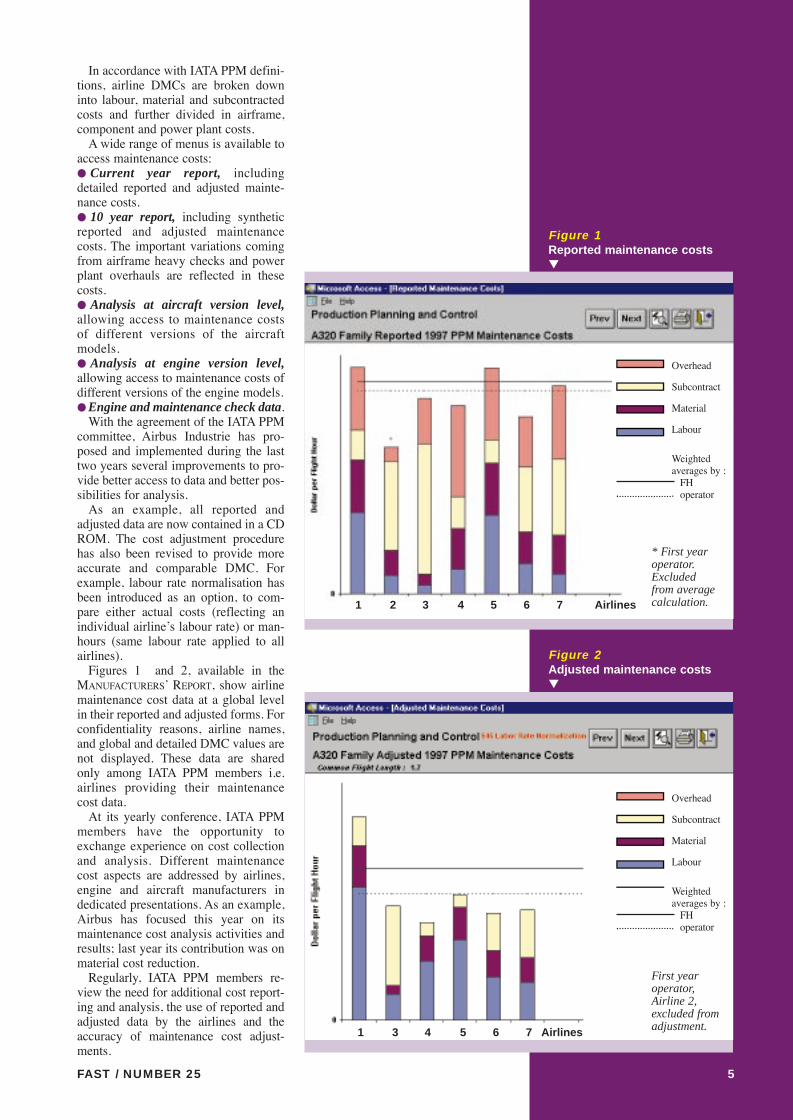
In accordance with IATA PPM defini-tions, airline DMCs are broken downinto labour, material and subcontractedcosts and further divided in airframe,component and power plant costs.
A wide range of menus is available toaccess maintenance costs:● Current year report, includingdetailed reported and adjusted mainte-nance costs.● 10 year report, including syntheticreported and adjusted maintenancecosts. The important variations comingfrom airframe heavy checks and powerplant overhauls are reflected in thesecosts.● Analysis at aircraft version level,allowing access to maintenance costsof different versions of the aircraftmodels.● Analysis at engine version level,allowing access to maintenance costs ofdifferent versions of the engine models.● Engine and maintenance check data.
With the agreement of the IATA PPMcommittee, Airbus Industrie has pro-posed and implemented during the lasttwo years several improvements to pro-vide better access to data and better pos-sibilities for analysis.
As an example, all reported andadjusted data are now contained in a CDROM. The cost adjustment procedurehas also been revised to provide moreaccurate and comparable DMC. Forexample, labour rate normalisation hasbeen introduced as an option, to com-pare either actual costs (reflecting anindividual airlineÕs labour rate) or man-hours (same labour rate applied to allairlines).
Figures 1 and 2, available in theMANUFACTURERSÕ REPORT, show airlinemaintenance cost data at a global levelin their reported and adjusted forms. Forconfidentiality reasons, airline names,and global and detailed DMC values arenot displayed. These data are sharedonly among IATA PPM members i.e.airlines providing their maintenancecost data.
At its yearly conference, IATA PPMmembers have the opportunity toexchange experience on cost collectionand analysis. Different maintenancecost aspects are addressed by airlines,engine and aircraft manufacturers indedicated presentations. As an example,Airbus has focused this year on itsmaintenance cost analysis activities andresults; last year its contribution was onmaterial cost reduction.
Regularly, IATA PPM members re-view the need for additional cost report-ing and analysis, the use of reported andadjusted data by the airlines and theaccuracy of maintenance cost adjust-ments.
FAST / NUMBER 25 5
Figure 1Reported maintenance costs▼
Figure 2Adjusted maintenance costs▼
* First yearoperator.Excluded from averagecalculation.
First yearoperator,Airline 2,excluded fromadjustment.1 3 4 5 6 7 Airlines
1 2 3 4 5 6 7 Airlines
Overhead
Subcontract
Material
Labour
Weighted averages by :
FHoperator
Overhead
Subcontract
Material
Labour
Weighted averages by :
FHoperator
fast 25 P1/P15 4/01/2000 11:40 Page 5

FAST / NUMBER 256
AIRBUS MAINTENANCE COST ANALYSES
CONCLUSION
Controlling maintenance costs is a crucial issue for airlines. Accurate cost reporting and proper cost adjustments are essen-tial to have fair comparisons and analyses. Airbus operators benefit from the considerable ability available within AirbusIndustrie to analyse and predict maintenance cost. Airlines also have the advantage of exchanging data and experience direct-ly with Airbus Industrie and through IATA PPM activities. ■
Figure 3A320 heavy check
man hours▼
Airbus Industrie has for many years per-formed its own maintenance cost analy-ses. They are based on data originatingfrom various sources, mainly reportsdirectly from airlines, but also fromIATA PPM, repair stations, equipmentsuppliers and engine shops.
Airbus Industrie pursues two ambi-tious objectives: ● To ensure through customised rec-ommendations that airlines get thecomplete benefit of its low maintenancecost design. This is achieved throughanalysis of airlinesÕ data, feedback oncost reduction opportunities and alsothrough accurate maintenance cost pro-jections for existing and potential cus-tomers.● To continually lower maintenancecosts and improve competitiveness ofexisting and future Airbus aircraft.This is achieved through actions with allconcerned parties to reduce mainte-nance costs for existing aircraft and alsoto set up objectives for future projects soas to achieve the lowest possible main-tenance and operating costs.
Some years ago Airbus Industriedeveloped a method placing emphasison the quality of reported data and onthe level of detail of the analyses.
● To ensure accuracy and consistencyof airlinesÕ data, reported DMCs are val-idated by the airline and Airbus togeth-er. ● Airbus Industrie performs cost com-parisons following a Òtop downÓapproach starting from maintenancecost at aircraft level. The analysis goesinto much detail, down to maintenancechecks, as shown in Figure 3, individualcomponents and expendable parts. Atpart number level, Airbus Industrie canprovide accurate technical and commer-cial recommendations to address themost costly items.● Airbus Industrie also provides a com-parison of the evolution of the reportedDMC with the customised Airbus DMCprojection. ● Finally, a dedicated feedback, high-lighting candidates for maintenance costreduction and associated recommenda-tions, is presented to the airline.
As an example, significant savingshave been achieved following compar-isons of airlinesÕ subcontracted costswith the market level. Results andamount of potential savings obviouslydiffer from one airline to the other.
Airbus Industrie supplies this serviceand data to contributing airlines.
Airlines A B C D E F G H
fast 25 P1/P15 4/01/2000 11:41 Page 6
FAST / NUMBER 25 7
by Alain NouvelSpares & Engineering Documentation
Department ManagerEngineering & Technical Support
Airbus Industrie Customer Services
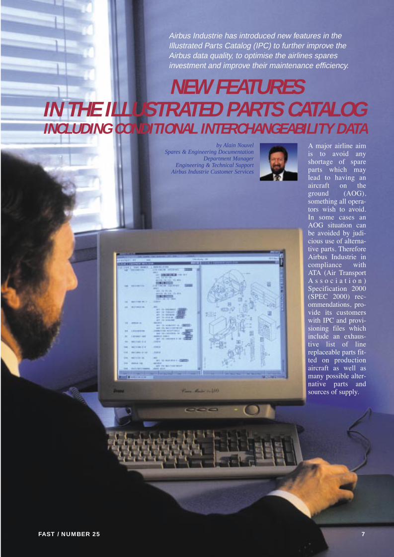
NEW FEATURESIN THE ILLUSTRATED PARTS CATALOGINCLUDING CONDITIONAL INTERCHANGEABILITY DATA
Airbus Industrie has introduced new features in theIllustrated Parts Catalog (IPC) to further improve theAirbus data quality, to optimise the airlines sparesinvestment and improve their maintenance efficiency.
A major airline aimis to avoid anyshortage of spareparts which maylead to having anaircraft on theground (AOG),something all opera-tors wish to avoid.In some cases anAOG situation canbe avoided by judi-cious use of alterna-tive parts. ThereforeAirbus Industrie incompliance withATA (Air TransportA s s o c i a t i o n )Specification 2000(SPEC 2000) rec-ommendations, pro-vide its customerswith IPC and provi-sioning files whichinclude an exhaus-tive list of linereplaceable parts fit-ted on productionaircraft as well asmany possible alter-native parts andsources of supply.
fast 25 P1/P15 4/01/2000 11:41 Page 7
IPC part number change data alreadyincludes all parts which are Òone wayÓ(coded INC1) or Òtwo wayÓ (codedINC2) interchangeable as well asoptional part numbers, preferred partnumbers and associated possiblesources of supply from optional vendorsor distributors.
In addition to this information the IPCwill indicate possible alternative partnumbers which could be installed undercertain conditions.
For those familiar with ATA SPEC2000, this particular information is cod-ified as Interchangeability codes (INC),for example INC4 defines parts “inter-changeable as a set” and INC5 repre-sents parts with “qualified interchange-
ability”. Basically these two definitionsrequire some additional concrete infor-mation in order to be analysed bymechanics and engineers.
To cover this particular relationship,the related part numbers in the IPC,provisioning files (S and V file) andRecommended Spare Parts Lists(RSPL) will be identified.
The introduction dates are as follows:¥ July 1999 for the A330 and the A340,¥ August 1999 for the A319, the A320and the A321,¥ December 1999 for the A300-600¥ and March 2000 for the A300.
ANNOUNCING PART NUMBER CHANGES
Previous IPC versions(Paper / film (cartridge)
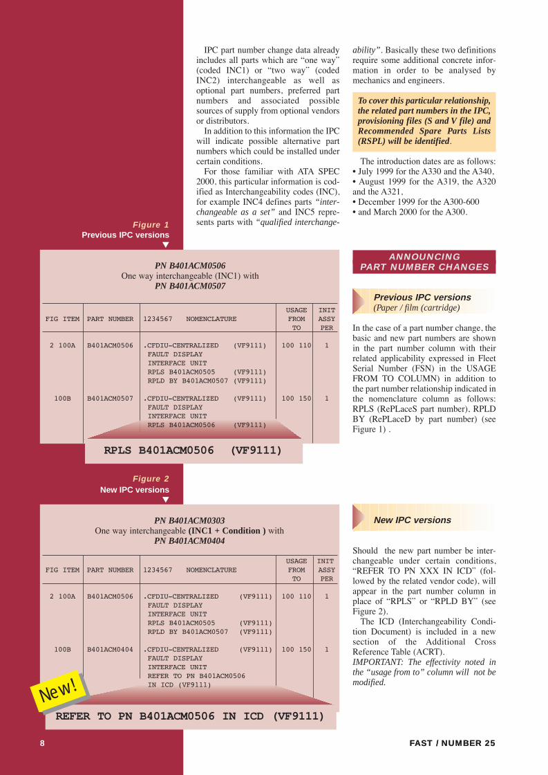
In the case of a part number change, thebasic and new part numbers are shownin the part number column with theirrelated applicability expressed in FleetSerial Number (FSN) in the USAGEFROM TO COLUMN) in addition tothe part number relationship indicated inthe nomenclature column as follows:RPLS (RePLaceS part number), RPLDBY (RePLaceD by part number) (seeFigure 1) .
New IPC versions
Should the new part number be inter-changeable under certain conditions,ÒREFER TO PN XXX IN ICDÓ (fol-lowed by the related vendor code), willappear in the part number column inplace of ÒRPLSÓ or ÒRPLD BYÓ (seeFigure 2).
The ICD (Interchangeability Condi-tion Document) is included in a newsection of the Additional CrossReference Table (ACRT).IMPORTANT: The effectivity noted inthe “usage from to” column will not bemodified.
FAST / NUMBER 25FAST / NUMBER 258
Figure 2New IPC versions
▼
PN B401ACM0303One way interchangeable (INC1 + Condition ) with
PN B401ACM0404
REFER TO PN B401ACM0506 IN ICD (VF9111)
USAGE INITFIG ITEM PART NUMBER 1234567 NOMENCLATURE FROM ASSY
TO PER
2 100A B401ACM0506 .CFDIU-CENTRALIZED (VF9111) 100 110 1FAULT DISPLAYINTERFACE UNITRPLS B401ACM0505 (VF9111)RPLD BY B401ACM0507 (VF9111)
100B B401ACM0404 .CFDIU-CENTRALIZED (VF9111) 100 150 1FAULT DISPLAYINTERFACE UNITREFER TO PN B401ACM0506 IN ICD (VF9111)
New!
PN B401ACM0506One way interchangeable (INC1) with
PN B401ACM0507
RPLS B401ACM0506 (VF9111)
USAGE INITFIG ITEM PART NUMBER 1234567 NOMENCLATURE FROM ASSY
TO PER
2 100A B401ACM0506 .CFDIU-CENTRALIZED (VF9111) 100 110 1FAULT DISPLAYINTERFACE UNITRPLS B401ACM0505 (VF9111)RPLD BY B401ACM0507 (VF9111)
100B B401ACM0507 .CFDIU-CENTRALIZED (VF9111) 100 150 1FAULT DISPLAYINTERFACE UNITRPLS B401ACM0506 (VF9111)
Figure 1▼Previous IPC versions
▼
fast 25 P1/P15 4/01/2000 11:42 Page 8

FAST / NUMBER 25 9
Figure 3 Example of InterchangeabilityCondition Document (ICD)▼
THE NEW IPC FEATURES ARE INCLUDEDIN THE FOLLOWING DOCUMENTS
In the Additional Cross Reference Table
The ACRT which supplements the IPC is supplied with each revision of the IPC. All ACRT information is valid for a given aircraft model (e.g. A319/A320 /A321,A330 or A340).
The ACRT contains:● The standard cross reference table (of non international standards)● The list of Functional Item Numbers (FIN)● Local manufacture cross reference table (X file)● Identification of lamps and fuses on A319/A320/A321, A330 and A340 film only● and, in addition, the new section called “Interchangeability Condition
Document” (ICD).This ICD contains (Figure 3) the following information:
● The basic part number and its associated CAGE code indicating the part numberthat the operator wants to replace.
● The related Functional Identification Numbers (FIN).● The IPC Catalog Sequence Numbers (CSN) including IPC figure and item
numbers.● The conditions/actions/information to be considered for installation of the
replacing part number.● The replacing part number and its associated CAGE code indicates the part
number which can be installed under the mentioned conditions, instead of the previous part number. .
FAST / NUMBER 25 99
fast 25 P1/P15 4/01/2000 11:42 Page 9

FAST / NUMBER 25
In the provisioning files (S, V, T,)
In compliance with the ATA SPEC 2000, conditional interchangeability betweentwo part numbers will be codified in the ÒSÓ file with the related Explanation Code(EC 06 or 07) and in the ÒVÓ file with the related Interchangeability Code (INC 4 or5).
The ÒSÓ and ÒVÓ file users have to refer to the IPC data to get theInterchangeability Condition Text (ICT).
The ICT has proven too complex to manage electronically within the scope of theSPEC 2000 provisioning files.
No conditional interchangeability codes will be managed for ÒTÓ File compo-nents.
In the Recommended Spare Parts List (RSPL)
Conditional interchangeability will be processed in the RSPL . The conditionsallowing the replacement of one or a set of components by another will be docu-mented in the ICD that will be part of the Line Replaceable Units (LRU) RSPL fold-er. Airbus Industrie will not modify the math model logic to process these particularconditions.
The recommendations will be processed with the basic interchangeability codes(INC 1 or 3) without taking the conditions into consideration.
The airlines will then be able to organize their inventory according to the optionsavailable.
In IPC SGML format
The SGML (Standard Generalized Mark-up Language) format (governed by theATA specification 2100), is used for the interchange of IPC textual information.
The conditions will also be provided in IPC SGML format to our customers usingthis particular data retrieval facility.
In the Component Evolution List (CEL)
The CEL part three Ò PART NUMBER CHANGE DATA Ò will also make refer-ence to the ICD.
In CD-ROM IPC (ADRES)
ADRES (Aircraft Documentation Retrieval System on CD-ROM) allows theretrieval of the Aircraft Maintenance Manual (AMM) and the IPC on a PC/Windowsenvironment.
Airbus Industrie is offering its customers the CD-ROM for the whole Airbus newgeneration family of Òfly-by-wireÓ aircraft, A319/A320/A321/A330/A340. Whenan alternative part number exists, ÒSEE PN CHANGEÓ appears in the nomenclaturecolumn. Double-clicking on this gives access to the following interchangeabilitydata (see examples in figure 4):● The basic part number and its associated CAGE code● The Interchangeability code Ò1Ó for ONE WAY, Ò2Ó for TWO WAY, Ò3Ó for NOT INTERCHANGEABLE● The replacing part number and its associated CAGE code. If a Conditional Interchangeability exists, the Interchangeability codewill be highlighted in grey. Double-clicking on this will give access to the relatedconditions or ICT .
Another major advantage of this new information is the possibility to clearly showdifferent interchangeability data depending on the location in the aircraft. As anexample, a part with the same part number installed in the cabin and near the enginemay be fully interchangeable in the cabin, but not interchangeable near the enginearea (perhaps due to high temperature).
The ICT is only related to a given aircraft model applicability: ❍ A310 or❍ A300-600 or❍ A319/A320/A321 or❍ A330 or A340.
FAST / NUMBER 2510
fast 25 P1/P15 4/01/2000 11:43 Page 10

11FAST / NUMBER 25 11
1
SEE PN CHANGE
BASIC PN INC REPLACING PN
SEE PN CHANGE
BASIC PN INC
3
XXX
XXX
REPLACING PN
Figure 4 ▼
fast 25 P1/P15 4/01/2000 11:43 Page 11

FAST / NUMBER 25FAST / NUMBER 2512
PRACTICAL EXAMPLE FOR LINE MAINTENANCE
To illustrate the advantage of these new IPC features, let us take a practicalexample for line maintenance mechanics:
You must replace a piece of equipment from the cockpit
STEP 1
✔ Locate this equipment and find the related part number by using the ACRT(Additional Cross Reference Table)
FIN 3XX1==> PN A1 IPC CSN 34-21-10 FIG 01 ITEM 120
To identify the reference of the part which was removed, you have two solutions:1. Either to note the part number (PN A1) from the removed unit 2. Or note the Functional Identification Number (FIN 3XX1) Ðlabel stuck close tothe equipment.
Using the IPC alpha numerical index in the first case, or the Additional CrossReference Table (ACRT) FIN to part number in the second case, you will be able todetermine the part number and the Catalog Sequence Number (CSN 34-21-10including the figure FIG 01 and item number ( ITEM 120) of the removedequipment.
STEP 2
✔ Select in ADRES the CSN 34-21-19-01-120 from your customized IPC
With this information you will be able to consult all related data in this particularfigure, and more particularly to check the spares availability with regards to thealternative parts mentioned in the IPC.
FAST / NUMBER 25
FIN:3XX1
ACRT Additional Cross Reference TableCAGE Commercial And Governmental EntityFSCM Federal Supplier Code of the ManufacturerICD Interchangeability Condition DocumentICT Interchangeability Condition Text
INC Interchangeability CodeIPC Illustrated Parts CatalogRSPL Recommended Spare Parts ListS/V& T files Provisioning files including spares parts
recommendation in compliance with ATA requirements
L I S T O F A B B R E V I A T I O N S
fast 25 P1/P15 4/01/2000 11:44 Page 12

✔ Check the Spares availability
● Spares availability check list:1. The removed part number (same PN)2. The optional part numbers (OPT TO PN -Fully interchangeable-)3. The preferred part number (Ò BUY PNÓ)
● In IPC on film:4. The replacing part numbers
(RPLD BY stands for Replaced By Ð one way interchangeable5. The replacing part numbers
(I/W stands for Interchangeable With ÐFully interchangeable6. Should you find the mention ÒSEE ICD FOR PNxxxxÓ denotes that
interchangeable parts under certain condition exists.7. Refer to the Additional Cross reference Table ICD (Interchangeability
Condition document ) section and check with your Engineering department whether the replacing PN proposed by Airbus Industrie can be acceptable for your particular aircraft.
● Using ADRES:8. The mention Ò SEE PN CHANGEÓ denotes that interchangeable
Part Numbers (One way or two way) are proposed9. The highlighted INC (interchangeability code) indicates that conditions
are linked to this particular PN change.10. In this case check with your Engineering department whether the
replacing part number proposed by Airbus Industrie can be acceptable for your particular aircraft.
FAST / NUMBER 25 13
STEP 3
FAST / NUMBER 25 13
Basic PN INC Replacing PNPN A1 2 PN C1PNC1 3 PNC2
Basic PN A1
Opt PN A2
Buy PN B3
Yes
No
Yes
Yes
No
YesNo
Spares on hand?
Install the PN A1
Install the PN A2
Install the PN B3
Install the PN C1
Action
CONDITIONPN C1 can be replaced by PN C2.
However, MMR function will be lost.
SEE PN CHANGE
CHECK THE CONDITION
IPC data
In this particular case:PN C1 and PN C2 are notinterchangeable. However assuming that only C2 isavailable and your engineering department acceptsthe condition, you can install for spares purposes thePN C2 instead of A1.
CONCLUSION
Through the dialogue with the engineering department, the line maintenance mechanic will have a wider choice of alterna-tive spares for his maintenance activity. Furthermore, with the incorporation of conditional interchangeability data in thespares documentation and in the provisioning files Airbus Industrie helps airlines to optimise the spares selection while main-taining and even improving their aircraft dispatch reliability. ■
OR
fast 25 P1/P15 4/01/2000 11:45 Page 13
FAST / NUMBER 2516
AA332200 FFAAMMIILLYYMMAAIINN LLAANNDDIINNGG GGEEAARR
SSeerrvviicciinngg tthhee ttwwoo--ssttaaggee sshhoocckk aabbssoorrbbeerr
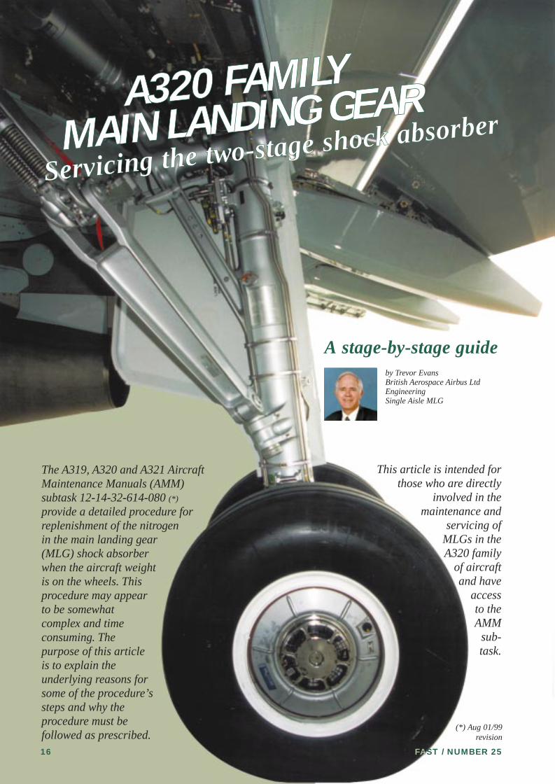
A stage-by-stage guideby Trevor EvansBritish Aerospace Airbus LtdEngineeringSingle Aisle MLG
This article is intended forthose who are directly
involved in themaintenance and
servicing ofMLGs in theA320 family
of aircraftand have
accessto theAMM
sub-task.
The A319, A320 and A321 AircraftMaintenance Manuals (AMM)subtask 12-14-32-614-080 (*)
provide a detailed procedure forreplenishment of the nitrogenin the main landing gear(MLG) shock absorberwhen the aircraft weightis on the wheels. Thisprocedure may appearto be somewhatcomplex and timeconsuming. Thepurpose of this articleis to explain theunderlying reasons forsome of the procedure’ssteps and why theprocedure must befollowed as prescribed.
(*) Aug 01/99revision
fast 25 P16/P32 4/01/2000 13:52 Page 16

FAST / NUMBER 25 17
Top charging valve - 1st stage
Oil level
Floatingpiston
1st stage chamber
2nd stage chamber
ÒHÓ
dim
ensi
on
2nd stagecylinder
Bottom charging valve - 2nd stage
The A319, A320 andA321 Main LandingGears all have two stageshock absorbers, whichwere chosen very earlyin the life of the A320following commentsfrom the operatorsregarding what theyperceived as over-firmlandings.
The procedure forservicing the mainlanding gears of eachaircraft is identical, withthe exception of thenitrogen pressures.These pressures varydepending upon theaircraft (A319/A320 andA321) to which theMLGs are fitted, creatinga shock absorber springcurve characteristic thatis best suited to thataircraft.
The two-stage shockabsorber comprises twonitrogen chambers,whose charging valvesare referred to in the AMM as the “topcharging valve” and the“bottom chargingvalve”.
In this article the upperchamber will be referredto as the 1st stage andthe lower chamber as the2nd stage.
fast 25 P16/P32 4/01/2000 13:55 Page 17

FAST / NUMBER 2518
The 1st stage is separated from the2nd stage by a floating piston containedin the 2nd stage cylinder as shown infigure 1.
Typically with a MLG temperature of20¡C and with no load on the shockabsorber the 1st stage is inflated to 7.6bar (110 psi) and the 2nd stage is inflat-ed to 78 bar (1132 psi) (A320-200 pres-sures). Initially, as the load on the shockabsorber is applied, it is only the nitro-gen pressure in the 1st stage thatincreases. With increasing load the 1ststage pressure will reach a value equalto the initial charge pressure of the 2ndstage (78 bar). Further increase in shockabsorber load, from this point onwards,causes the floating piston to start mov-ing down the 2nd stage cylinder and thepressures in both to equalize and remainequal for all further compression of theshock absorber. Figure 1 illustrates this
sequence and a typical pressure vsshock absorber closure curve is shownin figure 2. The portion of the curve A-B represents the 1st stage compressionand the portion of the curve B-C repre-sents the combined compression of the1st and 2nd stages. A set of curves likethis are presented in the AMM for main-tenance at different MLG temperatures.In the AMM these curves are calledDIAGRAM 1 and are shown in figure 3.
The first part of the procedure in theAMM provides a check to establishwhether the shock absorber closure(compression) is within acceptable lim-its for the measured temperature and 1ststage pressure. (Shock absorber closureis referred to in the AMM as the ÔHÕdimension). For any combination ofMLG temperature and 1st stage nitrogenpressure the corresponding ÔHÕ dimen-sion is given a tolerance of ±15mm. The±15mm tolerance on the ÔHÕ dimensionapplies only at this stage in the checkprocedure. When adding or removingnitrogen, during the procedure to correctthe ÔHÕ dimension, the required ÔHÕdimension is to be achieved within a tol-erance of ±2mm.
Before launching into the explana-tion of the servicing procedure it isworth defining what is meant by“MLG temperature”, “measuredtemperature”, etc. The AMM statesthat the temperature at the ‘topcharging valve’ is to be measured.Therefore the temperature should bemeasured using a thermometerwhose sensing element can be placedin contact with the top chargingvalve, such as a probe type digitalthermometer. This will provide a suf-ficiently accurate temperature to usein conjunction with the diagrams inthe AMM. It is important to under-stand that it is not the ambient airtemperature that is to be measured.
C D
B
A
ABCnormal spring curve
ABDSpring curve with extra pressurein 2nd stage for correction of the1st stage.
BDApplicable only duringreplenishment of 1st stage
First stage
nitrogenpressure
ÔHÕ dimension Shock absorber extendedShock absorber compressed
No load,weight off
wheels
78bars 78bars 90bars 115bars
7.6bars 50bars 90bars 115bars
Increasing aircraft weight
Floatingpiston
▲
Figure 1Shock absorber load versus
closure sequence
Figure 2Typical shock absorber
▼
fast 25 P16/P32 4/01/2000 13:57 Page 18

FAST / NUMBER 25 19
Figure 3AMM DIAGRAM 1It is important to bear inmind that the pressurerelates to the 1st stage(upper chamber) pressure
▼
Pressure in bars
ÔHÕ dimension in mm
Practical tipTape the temperatureprobe to leg at the startof the chargingoperation and allowtemperature tostabilise.
Digital thermometer with probe
fast 25 P16/P32 4/01/2000 13:58 Page 19

FAST / NUMBER 2520
When the ÔHÕ dimension is found tobe outside the ±15mm tolerance, replen-ishment of the nitrogen is required. Thereplenishment procedure is not as sim-ple as just adding or removing nitrogenfrom one nitrogen chamber or the other.
If this were to be done it would changethe ÔHÕ dimension to give the appear-ance of a correctly charged shockabsorber but with no certainty that thiswas the case. In fact all that may havebeen achieved is a new spring curvecharacteristic that has just one pressure/ÔHÕ dimension co-ordinate that lies onthe true spring curve.
When a shock absorber requiresreplenishment, and it is not convenientto jack the aircraft, what must be done?
The answer is that each nitrogenchamber must be serviced independent-ly. The procedure in the AMM is struc-tured accordingly: Subtask 12-14-32-614-080 para B (9) through para (26)deals with the correction of the 1st stageand para (27) through para (36) dealswith the correction of the 2nd stage.Both parts of the procedure MUST be
completed. There are no short cuts.The 1st stage nitrogen chamber is ser-
viced first. But before this can be donethe 2nd stage must be isolated and madeinactive. The 2nd stage is made inactiveby adding nitrogen at the bottom charg-ing valve to move the floating piston tothe top of the 2nd stage cylinder. Thiscondition is achieved when sufficientnitrogen has been added to make thepressure in the 2nd stage cylinder 18 bar(260 psi) greater than the 1st stage nitro-gen pressure (para (17)). This effective-ly converts the leg into a single-stageshock absorber whose spring curve isshown in figure 3 by the curve A-B-D,which is simply an extrapolation of thecurve A-B. A set of curves like this arepresented in the AMM for maintenanceat different MLG temperatures. In theAMM these curves are referred to asDIAGRAM 2 and are shown in figure 4.
Subtask para (18) starts the part of theprocedure that corrects the nitrogen vol-ume in the 1st stage chamber.
At this point in the procedure it isworth explaining that the pressure in the1st stage chamber is directly related toaircraft weight (i.e. the load on the shockabsorber). Adding or removing nitrogenfrom the 1st stage chamber is not intend-ed to change this pressure; rather it is tochange the volume of nitrogen. Forinstance, adding nitrogen will increasethe ÔHÕ dimension which increases thevolume in the 1st stage chamber whilstkeeping the pressure constant and con-sistent with the aircraft weight.
There is, however, just to makethings a little more complicated, anexception. This exception ariseswhen nitrogen is initially added orremoved. The initial addition orremoval of nitrogen will change thepressure because the friction forcesthat exist in the shock absorbersliding components will inhibit animmediate change in ‘H’ dimension.This is why the procedure states thatthe initial addition or removal ofnitrogen must stop immediately theshock absorber starts to move. Atthis point the force generated by thechange in nitrogen pressure is inbalance with the friction force.
The new nitrogen pressure thus gener-ated is the pressure that must be used inconjunction with AMM DIAGRAM 2.This determines the correct ÔHÕ dimen-sion to be achieved when the addition orremoval of nitrogen is recommenced.When the addition or removal of nitro-gen is recommenced the ÔHÕ dimensionwill smoothly change at constant 1st
Figure 4AMM DIAGRAM 2
▼
ÔHÕ dimension in mm
fast 25 P16/P32 4/01/2000 13:59 Page 20

stage pressure. The reason why the fric-tion forces and the nitrogen pressuregenerated forces need to be balanced isfurther explained in figure 5.
This first part of the procedure, to cor-rect the 1st stage nitrogen volume, isinterspersed with check readings ofpressure, temperature and ÔHÕ dimen-sion. These checks are to ensure that
previously achieved conditions haveremained unchanged and that a suffi-ciently-high pressure-differential bet-ween the 1st and 2nd stage pressures hasbeen maintained. This will ensure thatthe floating piston is still at the top ofthe cylinder, i.e the pressure in the 1ststage is at least 11 bars lower than thepressure in the 2nd stage.
▲
Figure 5• H1 - Measured ‘H’ dimension at
the pressure P1 showing an error in ‘H’ equal to (H2-H1).
• H3 - ‘H’ dimension to be achieved obtained from curve AFTER measuring new pressure P2.
FAST / NUMBER 25 21
1st
stag
e pr
essu
re
P2
P1
H1 H3 H2
1.1st stage pressure (P1)and H dimension (H1)
measured and found notto lie on curve at P1/H2.
2.Nitrogen added.
Shock absorber does notmove. Pressure increases
from P1 to P2.
3.Point at which shock
absorber starts to move.Stop adding nitrogen.
Measure new pressure P2.
4.This is whereyou want to be...
5.... but you willfinish at thispoint if the newpressure (P2) isnot measured toobtain the newdimension (H3).
1
3 4 5
2
ÔHÕ dimension
The ‘H’ dimension
‘H’
fast 25 P16/P32 4/01/2000 14:00 Page 21

FAST / NUMBER 2522
On completion of subtask para (25)the 1st stage nitrogen volume is correct.BUT remember that the 2nd stage mustnow be corrected.
The next part of the procedure is tocorrect the 2nd stage. How this isachieved is dependent on the weight ofthe aircraft, because at the end of the2nd stage charging procedure it is possi-ble for one of two conditions to exist:● Condition (a)The weight of the aircraft is such thatthe shock absorber will be operating onthe 1st stage of the spring curve Ð some-where along the curve A-B of figure 2.The floating piston is still at the top ofthe 2nd stage cylinder. (The aircraft isrelatively light)● Condition (b)The weight of the aircraft is such thatthe shock absorber will be operating onthe 2nd stage of the spring curve Ðsomewhere along the curve curve B-Cof figure 2. The floating piston is atsome intermediate position within the2nd stage cylinder. (The aircraft is rela-tively heavy)
The AMM deals with these conditionsseparately. Subtask para (27) is the pro-cedure for condition (a) and subtaskpara (28) is the procedure for condition(b). It is not necessary to know the actu-al aircraft weight because the procedurethat is used is determined by the
1st stage pressure and its position rela-tive to the line on ÔDIAGRAM 3Õ in theAMM. It is shown in figure 6 and showsthe relationship between the 2nd stagepressure and temperature when thefloating piston is at the top of the cylin-der.
If the 1st stage pressure is such that itis below the line on diagram 3 it meansthat the aircraft weight has generated a1st stage pressure that is not greatenough to cause the floating piston tomove down from its position at the topof the cylinder. Therefore all that needsto be done in this case, is to removenitrogen from the 2nd stage cylinder tomake the pressure agree with the line onDIAGRAM 3. It is important that thisfinal step is performed even thoughthere will be no change in the ÔHÕdimension. If it is not done the 2nd stagewill remain over pressurised. For condi-tion (a) the procedure is now complete.
If the 1st stage pressure is such that itis above the line on DIAGRAM 3, itmeans that the aircraft weight has gen-erated a sufficiently high 1st stage pres-sure to overcome the initial charge pres-sure of the 2nd stage cylinder and hasmoved the floating piston away from itsstop at the top of the cylinder. In thiscase it is necessary to adjust the volumeof nitrogen in the 2nd stage to obtain thefinal correct ÔHÕ dimension. As theshock absorber will be operating on the2nd stage of the spring curve refer nowto DIAGRAM 1 in the AMM to deter-mine the ÔHÕ dimension that is to beachieved to complete the procedure.Nitrogen is removed from the 2nd stagecylinder by following the same proce-dure for removing nitrogen from the 1ststage. In this case nitrogen is removedfrom the 2nd stage cylinder until theshock absorber just starts to move.When this occurs, stop removing nitro-gen and re-measure the 1st stage nitro-gen pressure. Use this pressure to deter-mine the correct ÔHÕ dimension fromDIAGRAM 1. Re-commence removingnitrogen from the 2nd stage cylinderuntil the desired ÔHÕ dimension isachieved. For condition (b) the proce-dure is now complete.
CONCLUSION
The two-stage shock absorber is necessary to give the desired passenger comfortlevels when landing the aircraft and it is equally necessary that the chargingsequence described in the AMM be adhered to. It is important to remember dur-ing the nitrogen replenishment sequence, that an over-pressurised, or under-pres-surised shock absorber has the potential for causing internal damage to shockabsorber components and of course discomfort to the aircraftÕs occupants! Theinformation provided in this article will help to ensure that main landing gearsand passengers will always have happy landings. ■
90
80
70
60
-40 40 50 60-30 30-20 20-10 100
INFL
ATIO
N PR
ESSU
RE b
ar
TEMPERATURE °C
Figure 6AMM DIAGRAM 3
Relationshipbetween the 2nd
stage pressure andtemperature (the
piston is at the topof the cylinder).
▼
fast 25 P16/P32 4/01/2000 14:01 Page 22
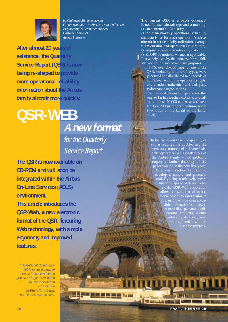
The current QSR is a paper documentissued for each aircraft type and containing:❍ each aircraftÕs life history,❍ the main monthly operational reliabilitycharacteristics for each operator (such asaircraft in service, daily utilisation, averageflight duration and operational reliability*)❍ engine removal and reliability data❍ ETOPS operations, whenever applicable.It is widely used by the industry for reliabil-ity monitoring and benchmark purposes.
In 1998, over 20,000 paper copies of theQSR, including all aircraft types, wereproduced and distributed to hundreds ofaddressees within the operators, suppli-ers, aviation authorities and 3rd partymaintenance organisations. The required amount of paper for thisyear so far has reached 6.5 tons, and pil-ing up those 20,000 copies would haveled to a 200 meter-high column, abouttwo thirds of the height of the Eiffeltower.
In the last seven years the quantity ofcopies required has doubled and theincreasing number of delivered air-craft, operators, and aircraft types ofthe Airbus family would probablyrequire a further doubling of thepaper volume in the next five years.There was therefore the need todevelop a simple and practicaltool. By using a relatively recent
but wide spread Web technolo-gy, the QSR-Web application
allows consultation of opera-tional reliability information ata glance. By providing acces-sible Mircosoft¨ Excelsource files, personal appli-cations requiring Airbusreliability data may nowbe updated without
need for retyping.
14
by Catherine Simonne-JondotGroup Manager - In-Service Data CollectionEngineering & Technical SupportCustomer ServicesAirbus Industrie
After almost 20 years ofexistence, the QuarterlyService Report (QSR) is nowbeing re-shaped to providemore operational reliabilityinformation about the Airbusfamily aircraft more quickly.
The QSR is now available onCD-ROM and will soon beintegrated within the AirbusOn-Line Services (AOLS)environment. This article introduces theQSR-Web, a new electronicformat of the QSR, featuringWeb technology, with simpleergonomy and improvedfeatures.
*Operational Reliability=100% minus the rate of
revenue flights involving aground or flight interruption
(Delay/Cancellation or Diversion/
In-Flight Turn Back), per 100 revenue take-offs.
QSR-WEB A new format for the Quarterly Service Report
FAST / NUMBER 25
fast 25 P1/P15 4/01/2000 11:46 Page 14

FAST / NUMBER 25 23
The aviation industry has onlyrecently started to fully recognize the valueof digital technical data but Airbus Industriehas been working on the necessaryfoundations for today’s digital data productsand services since the beginning of the1990s.
Airbus Industrie delivered the firstAircraft Maintenance Manual and IllustratedParts Catalog in SGML (StandardGeneralized Markup Language) to airlines inJuly 1993. In July 1994 it launched digitaldata consultation tools using the CD-ROMtechnology with ADRES (AircraftDocumentation Retrieval System) containingthe Maintenance Manual and Illustrated PartsCatalog. One year later CAATS (ComputerAssisted Aircraft Trouble Shooting) a specifictrouble shooting tool became available.Since then, Airbus Industrie has developed awide range of digital technical data productsto support the consultation and processingof technical data by the airlines. Until now, allthese products were delivered off-line oncomputer tapes, floppy disks or CD-ROMs.
With the availability and growinginfluence of Internet and Web technology,Airbus Industrie has decided to put in placethe necessary means to support on-lineaccess to its Technical Data in a secure andreliable system environment.
AIRBUS INDUSTRIEDRAWINGACCESS
On-line access to AirbusEngineering Drawings
Dr. Andreas Schuetze, Group Manager
Digital Technical Data SupportTechnical Data & Documentation
Airbus Industrie Customer Services
Danièle KirkManager of Technical Library
Technical Data & DocumentationAirbus Industrie Customer Services
Jean-Louis LamotteInformation Systems Manager
AIDA Project LeaderAirbus Industrie Customer Services
fast 25 P16/P32 4/01/2000 14:03 Page 23
AIRBUS ON-LINE SERVICES
All future on-line access to Airbusservices will be provided as far
as possible through one single interfacecalled Airbus On-Line Services(AOLS). The general AOLS architec-ture is characterised by:● utilisation of standard hardware (PCPentium)● use of standard software tools (Webbrowser, Acrobat Reader and otherplug-ins)● on-line access via TCP/IP network ● information access through a com-mon user interface● specific access rights for each cus-tomer● user authentication through the use ofcertificates (standard X.509 V3)● data integrity during transfer throughthe use of the Secure Socket Layer(SSL) protocol● upload and download functions forTechnical Data● availability 24 hours per day, 365days per year.
Customers who want to connect toAOLS are not required to use a particu-lar network connection but Airbus rec-ommends the use of SITA AeroNet.AeroNet represents a worldwide avail-able private network, dedicated to theaerospace industry that is based onInternet standards. It is secure and reli-able and it guarantees the capacity of thenetwork connection.
This article focuses on AIDA. It isfully ÒAOLS compliantÓ in terms ofhardware and software architecture, net-work connection, security and userinterface. It is undergoing its pilot phasewith ten airline customers.
AIDA represents a new way of dis-tributing drawings, which will replacedrawings supplied on microfilm aper-ture cards and film cartridges for associ-ated data. Up to now each new operatorreceived with its first aircraft a packageof between 80,000 and 120,000 drawingaperture cards with a set of associateddata on film. These aperture cards andfilms were subject to updates to coverpossible configuration changes of addi-tional aircraft.
Depending on the size of the operatorand its fleet, some airlines have to facethe management of several collectionsreaching to some 1.8 million drawingaperture cards. Sometimes AirbusIndustrie was asked to supply severalsets of engineering drawings, requiredby the airline for maintenance, overhaulor repair at different locations.
With engineering drawings on-line,the airline will be relieved of the heavytask of keeping up-to-date the huge col-lections of drawing aperture cards. The
current possibility of the misplacing anaperture card is removed. Also the timespent in searching for drawings andinformation will be drastically reduced.
AIDA provides the airlines with on-line access to mechanical drawings forall major aircraft assemblies, sub-assemblies and installations, for thewhole fleet of Airbus aircraft. Access todrawings of detail parts is the subject ofcontract negotiation.
The drawings available in the AIDAservice reflect the latest productiondrawing evolution (last issue). As withthe aperture cards, drawings of non-Airbus proprietary parts are not includ-ed in the service. AIDA gives on-lineaccess to the technical drawing set ofairframe structure, payload and mechan-ical systems.
A drawing consists of three separatedocuments: ● the Drawing Picture (graphical part)● the Parts List (also called Bill ofMaterials or Schedule)● the Parts Usage, which provides thenext higher assembly (NHA) with corre-sponding aircraft effectivities.
All three documents bear the samenumber. This is the number that the userwill enter in the Reference box on thequery screen, before selecting whichone of the three documents, DrawingPictures (Picture Sheet), Parts List, orParts Usage to be displayed.
With AIDA it is possible for the userto view and print either the informationon the screen or the complete drawingset in a few seconds. It is also possibleto zoom and rotate within a specific areaof the drawing and to obtain an enlargedsection of the drawing.
The Parts List and the Parts Usageenable the navigation within the draw-ing hierarchy from the aircraft generalassembly down to detail parts, and theinverse.
The Parts List calls up all parts, sub-assemblies and items that are shown onthe Drawing Picture sheet (detail parts,components and standard parts). On thepicture, detail parts are indicated with aballoon, which provides a cross-refer-ence between the Parts List and theDrawing Picture.
All drawn parts bear a part numberderived from its drawing number byadding three additional digits. Theinquiry by the part number will displaythe Parts List information related to thispart.
To obtain the next higher assembly ofa part, the user will select the PartsUsage. The Parts Usage displays thepart variants (3-digit suffix) with theirassociated next higher assemblies andeffectivities expressed in customer ver-sion/rank.
FAST / NUMBER 2524
The first stage of AOLS,following intensive pilot testingduring 1999, will gradually bemade available to all customers.It will offer access to thefollowing services:
● AIDA (Airbus IndustrieDrawing Access) Service ● Engineering Technical DataService (access to SB, TFU, MID,SIL, AOT, FOT, OIT, AD/CN)● FCOM (Flight Crew OperatingManual) Service.
The Airbus objective is to startthe industrial phase for thesethree services in the first quarterof year 2000.
Shortly afterwards, the BFEMS(Buyer Furnished EquipmentManagement System) service,followed by the Spare PartsService (today this is a separateInternet application) and otherservices will be integrated intoAOLS.
fast 25 P16/P32 4/01/2000 14:05 Page 24
PUTTING AIDA TO TESTWITH AIRBUS ENGINEERS
Currently the Airbus Technical Librarymanages more than one million aperturecards. In order to reduce that manage-ment two AIDA consultation stationswith a dedicated high-resolution printer
capable of printing pages in A3 formathave been installed. The system is usedon a self-service basis and perceived asvery user-friendly by the CustomerSupport engineers dealing with draw-ings. Assuming that the user alreadyworks in a Windows environment, min-imum guidance is required.
FAST / NUMBER 25 25
The main functions of AIDA
DIRECT ACCESS TO A DRAWING
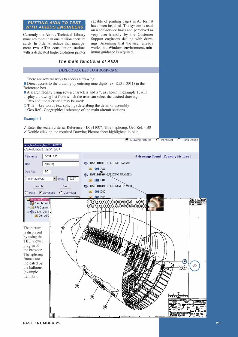
There are several ways to access a drawing:● Direct access to the drawing by entering nine digits (ex: D53110011) in theReference box ● A search facility using seven characters and a *, as shown in example 1, willdisplay a drawing list from which the user can select the desired drawing.
Two additional criteria may be used:❍ Title - key words (ex: splicing) describing the detail or assembly ❍ Geo Ref - Geographical reference of the main aircraft sections.
Example 1
✓ Enter the search criteria: Reference - D531100*, Title - splicing, Geo Ref. - B0✓ Double click on the required Drawing Picture sheet highlighted in blue.
The pictureis displayedby using theTIFF viewerplug-in ofthe browser.The splicingframes areindicated bythe balloons(exampleitem 35).
35
fast 25 P16/P32 4/01/2000 14:05 Page 25

TOP-DOWN NAVIGATION IN THE DRAWING HIERARCHYUSING THE PARTS LIST
This can be accomplished, for example by selecting the Parts List option in the con-textual area (command bar) above the Drawing Picture, and the Parts List will bedisplayed. Clicking on one of the blue-highlighted part numbers allows navigationto the next-lower assembly.
Example 2
Looking for the drawing of item 35 (see example 1):✓ Click on the blue-highlighted part number reference within the Parts List:
FAST / NUMBER 2526
Then AIDA both updates
● the hierarchical navigation tree,
● and displays the Parts List of this drawing.
✓ Clicking on the Sheet link displays the Picture Sheet of the part.
Starting with a givendrawing, it is possible to
navigate downwards or upwards through the
drawing hierarchy.
fast 25 P16/P32 4/01/2000 14:06 Page 26
✓ Then click on one of its blue-highlighted next-higher assemblies:
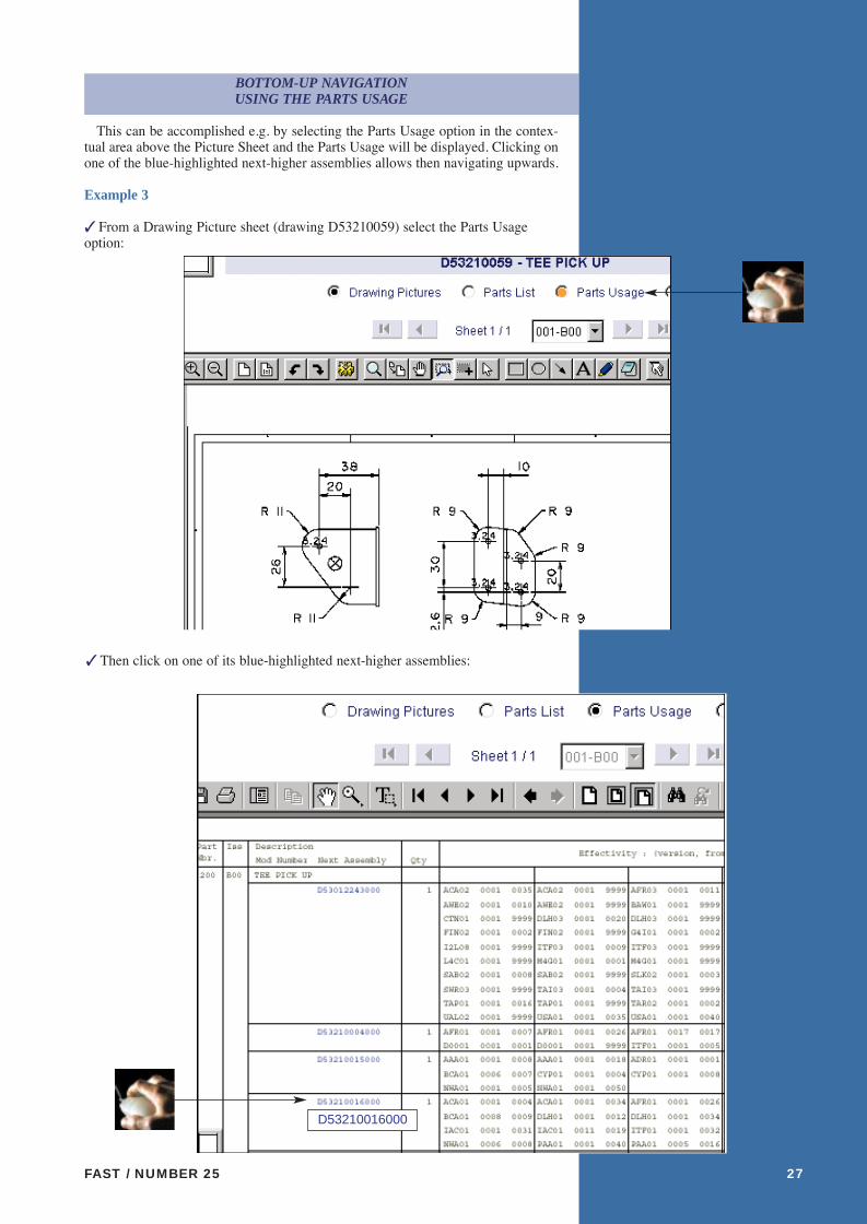
BOTTOM-UP NAVIGATION USING THE PARTS USAGE
This can be accomplished e.g. by selecting the Parts Usage option in the contex-tual area above the Picture Sheet and the Parts Usage will be displayed. Clicking onone of the blue-highlighted next-higher assemblies allows then navigating upwards.
Example 3
✓ From a Drawing Picture sheet (drawing D53210059) select the Parts Usageoption:
FAST / NUMBER 25 27
D53210016000
fast 25 P16/P32 4/01/2000 14:06 Page 27
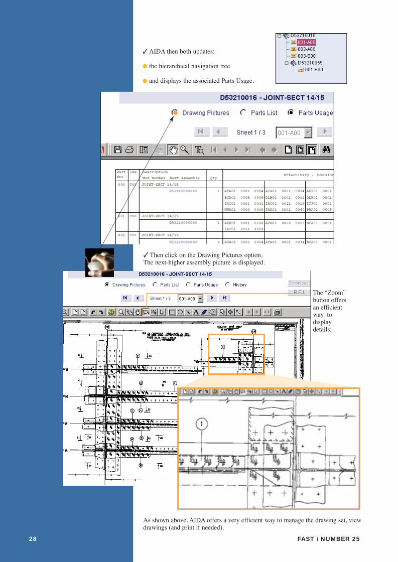
✓ AIDA then both updates:
● the hierarchical navigation tree
● and displays the associated Parts Usage.
FAST / NUMBER 2528
The ÒZoomÓbutton offersan efficientway todisplaydetails:
As shown above, AIDA offers a very efficient way to manage the drawing set, viewdrawings (and print if needed).
✓ Then click on the Drawing Pictures option.The next-higher assembly picture is displayed.
fast 25 P16/P32 4/01/2000 14:07 Page 28

HARDWARE AND SOFTWARE REQUIREMENTS
The following prerequisites are required in terms of network connection, hardwareand software in order to be able to connect to AIDA:¥ TCP/IP network connection - Airbus recommends a minimum bandwidth of 256kbit/s and will support: AeroNet, Internet, ISDN, PSTN, direct lines¥ Pentium 166 MHz with 64 MB RAM¥ 17ÔÕ screen (1024 x 768), but 20ÕÕ screen is recommended¥ 1 GByte hard drive¥ Windows 95, 98, NT4¥ 300 dpi A3/A4Laser Printer, Adobe compliant. (A3 is necessary to be able to readthe majority of drawings).Netscape Navigator 4.51 or (from year 2000 onwards) Internet Explorer 5.0 forsecurity reasons¥ Browser plug-ins:- TIFF plug-in recommendations (ViewDirector Prizm 2.3 or CSView 150)- PDF plug-in: Acrobat Reader 3.01 or higher
Access to AOLS and AIDA will be the subject of a commercial agreementbetween Airbus Industrie and the user.
Airbus Industrie is investigating the possibility of including additional drawingfamilies in the service such as tool drawings and electrical drawings. ■
FAST / NUMBER 25 29
Should you need more information on AOLS and AIDA, please contact:Dr. Andreas Schuetze, Group Manager Digital Technical Data SupportTechnical Data & DocumentationAirbus Industrie Customer Services DirectorateTel: +33 (0) 5 61 93 41 66Fax: +33 (0) 5 61 93 28 06E-mail: [email protected]
L I S T O F A B B R E V I A T I O N S
AD Airworthiness DirectiveADRES Aircraft Documentation REtrieval SystemAIDA Airbus Industrie Drawing AccessAOLS Airbus On-Line ServicesAOT All Operators TelexBFEMS Buyer Furnished Equipment Management SystemCAATS Computer Assisted Aircraft Trouble ShootingCD-ROM Compact Disk - Read Only MemoryCN Consigne de NavigabilitéFCOM Flight Crew Operating ManualFOT Flight Operations TelexISDN Integrated Services Data NetworkMID Modification Information DocumentOIT Operators Information TelexPDF Portable Document FormatPSTN Public Switch Telephone NetworkSB Service BulletinSGML Standard Generalized Mark-up LanguageSIL Service Information LetterTCP/IP Transmission Control Protocol/Internet ProtocolTFU Technical Follow-UpTIFF Tagged Information File Format
fast 25 P16/P32 4/01/2000 14:07 Page 29

FAST / NUMBER 25 15
The QSR-Web application can be runwith either MSIE5 on a Macintosh com-puter, or Netscape¨ 4.51 browser ver-sions on a PC. The minimum pre-requi-sites are delivered with the QSR-WebCD-ROM, which also includes adetailed userguide to provide you withnecessary information to install (ifrequired) the Web browsers, start theapplication, use the button bar and evensome troubleshooting advice.
After launching the application, thelegal terms of use precede the main pre-sentation screen “Airbus QuarterlyService Report”, the layout of which issimilar to the AOLS environment. Thisis followed by access to a navigationtree allowing selection of the requiredaircraft type. For each aircraft type, animage appears with a colored shade sim-ilar to the cover of the correspondingpaper version of the QSR.
The sections available for access aresimilar to those available in the paperbooklets. When selecting the “airlinedata” section, it is easy to switch fromthe data table for a given operator to theassociated graphs by clicking on thelink: “Show Graph”.
The new CD-ROM version of the QSRpresents a range of improvements such as:● improved ergonomy, with a 50g CD-ROM instead of two kilogrammes ofpaper copies for the existing eight air-craft types● earlier availability (2 to 3 weeksreduction in the QSR productionprocess)● simultaneous information on allAirbus aircraft types● access to the Excel source files toavoid the retyping of reliability data● sharing possibilities by installing theapplication on a network● a user friendly but also Òenvironmen-tally friendlyÓ product with its recy-clable cardboard cover; which savestrees as well as time.
Very soon, access to QSR-WEB willbe possible via AOLS.
A simplified paper version of the QSRwill be maintained until the end of theyear so that all the QSR readers get theirEDP equipment upgraded to processCD-ROMs or access AOLS. Howeverall the benefits of the QSR-Web men-tioned above justify the discontinuationof a paper service by 2000.
FAST / NUMBER 25 15
Home Back Forward Full screen Print Source Help
Command buttons allow for an easy navigation and use of the documents:
To make or modify a subscription,to simply get any information on thefree of charge quota of CD-ROMsgranted, or to provide feedback on theQSR Web product, please contact:AIRBUS INDUSTRIE AI/SE-M11 ReliabilityIn-Service Data Collection GroupTel : 33(0)5 61 93 29 41Fax : 33(0) 5 61 93 28 72Email: [email protected]
The QSR-WEB on a CD-ROM benefits the user by providing more information,more quickly, in a user-friendly Microsoft ¨ Excel format, allowing updating ofthe userÕs personal files without need for typing. Also the weight of a set of infor-mation on the whole Airbus fleet is reduced by 97,5% with the associated reduc-tion in storage volume. New technology for the benefit of all. ■
Operational Interruptions
Show graph
fast 25 P1/P15 4/01/2000 11:47 Page 15
FAST / NUMBER 2532
Technology in the year
2000
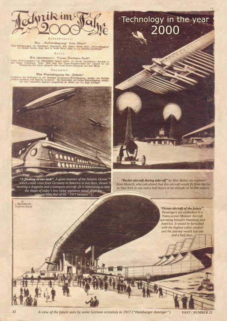
A view of the future seen by some German scientists in 1917 (“Hamburger Anzeiger”).
“Rocket aircraft during take-off” by Max Balier, an engineer from Munich, who calculated that this aircraft would fly from Berlinto New York in one and a half hours at an altitude of 50,000 meters.
“A floating ocean tank”. A giant monster of the Atlantic Oceanwhich could cross from Germany to America in two days, shown
meeting a Zeppelin and a transport aircraft. (It is interesting to notethe shape of today’s low radar signature naval ships are
approaching that of the “1917 monster”.)
“Ocean aircraft of the future”.Passengers are embarked in aTrans-ocean Monster Aircraft
operating between Hamburg andAmerica. It would be furnishedwith the highest cabin comfortand the journey would last one
and a half days.
fast 25 P16/P32 4/01/2000 14:10 Page 32

FL
IG
HT
A
IR
WO
RT
HI
NE
SS
S
UP
PO
RT
T
EC
HN
OL
OG
Y
As an airline operator, your number one priority is to optimise the performance and profitability of your fleet.
At Airbus, we constantly track our aircraft , monitoring everything from flight cycles and hours to
efficiency and reliability. By sharing this experience with all our operators, we ensure that
your aircraft are fully utilised and help you avoid any potential problems by keeping you
one step ahead. Airbus Customer Services. Dedicated to meet your requirements.
ht tp://www.a i rbus.com
OU R ENG I N EER I NG SU PPORT CAN MAKE YOU RS A N U M B ER ON E A I R L I N E .
SETTING THE STANDARDS
AIRBUS
Cover / backcover 4/01/2000 11:19 Page 1

FAST / NUMBER 25 FAST / NUMBER 2530 31
RCSM LOCATION COUNTRY ABU DHABI United Arab Emirates AMMAN Jordan ATHENS Greece ATLANTA USABOMBAY IndiaBANGKOK Thailand BEIJING People’s Republic of ChinaBEIRUT LebanonBERLIN GermanyBIRMINGHAM EnglandBOGOTA ColumbiaBRUSSELS BelgiumBUENOS AIRES Argentina CAIRO Egypt CHARLOTTE USA (North Carolina) CHENGDU People’s Republic of ChinaCINCINNATI USA (Ohio)COLOMBO Sri Lanka COPENHAGEN DenmarkDAKAR Senegal DHAKA BangladeshDAMASCUS Syria DELHI India DERBY England
C U S T O M E R S U P P O R T
USA / CANADAThierry van der Heyden, Vice President Customer ServicesTelephone: +1 703 834 3484 / Telefax:+1 703 834 3464
CHINAEmmanuel Peraud, Director Customer ServicesTelephone: +86 10 6456 7720 / Telefax: +86 10 6456 76942 /3 /4
REST OF THE WORLDMohamed El-Borai, Vice President Customer Support Services DivisionTelephone: +33 (0) 5 61 93 35 04 / Telefax:+33 (0) 5 61 93 41 01
RESIDENT CUSTOMER SUPPORT ADMINISTRATIONPhilippe Bordes, Director of Resident Customer Representation Administration Telephone: +33 (0) 5 61 93 31 02 / Telefax:+33 (0) 5 61 93 49 64
T E C H N I C A L , S P A R E S , T R A I N I N G
Airbus Industrie has its main spares store in Hamburg, Germany, and subsidiary stores at Frankfurt, Germany, Washington D.C., Beijing, China, and Singapore.Airbus Industrie operates 24 hours a day every day.
AOG technical and spares calls in North America should be addressed to:Telephone +(1) 703 729 9000Fax +(1) 703 729 4373
AOG technical and spares calls outside North America should be addressed to:Telephone +(49) 40 50 76 3001 / 3002 / 3003Fax +(49) 40 50 76 3011 / 3012 / 3013
Airbus Industrie's main training centre is locatedat Toulouse, France.Telephone +33 (0) 5 61 93 33 33Fax +33 (0) 5 61 93 46 65
It has major training subsidiaries located at Miami, FloridaTelephone +1 305 871 36 55Fax +1 305 871 46 49
and Beijing, ChinaTelephone +86 10 64 57 33 40Fax +86 10 64 57 09 64
RCSM LOCATION COUNTRY MEXICO CITY Mexico MIAMI USA (Florida) MINNEAPOLIS USA (Minnesota) MONASTIR TunisiaMONTREAL Canada MOSCOW Russia MUMBAI India NAIROBI Kenya NANCHANG People’s Republic of ChinaNANJING People’s Republic of ChinaNEW YORK USA (New York) NUREMBERG GermanyPARIS (CDG) France PARIS (ORY) France PHILADELPHIA USA (Pennsylvania)PHOENIX USA (Arizona) PITTSBURG USA (Pennsylvania)PUSAN South Korea QUINDAO People’s Republic of ChinaRALEIGH USA (North Carolina)ROME Italy SAN’A YemenSAN FRANCISCO USA (California) SAN JOSE Costa Rica SAN SALVADOR El SalvadorSAO PAULO BrazilSEOUL South Korea SHANGHAI People’s Republic of ChinaSHANNON Ireland SHENYANG People’s Republic of ChinaSHENZHEN People’s Republic of ChinaSINGAPORE Singapore TAIPEI Taiwan TAMPA USA (Florida)TASHKENT Uzbekistan TEHRAN Iran TOKYO (HND) Japan TORONTO Canada TULSA USA (Oklahoma) TUNIS Tunisia VANCOUVER Canada VIENNA AustriaWINNIPEG Canada XIAN People’s Republic of ChinaZAGREB CroatiaZURICH Switzerland
RCSM LOCATION COUNTRY DETROIT USA (Michigan)DOHA QatarDUBAI United Arab Emirates DUBLIN Ireland DULUTH USA (Minnesota)DUSSELDORF Germany FRANKFURT Germany GUANGZHOU People’s Republic of ChinaHANGHZOU People’s Republic of ChinaHANOI VietnamHELSINKI FinlandHONG KONG People’s Republic of ChinaINDIANAPOLIS USA (Indiana)ISTANBUL Turkey JAKARTA Indonesia JOHANNESBURG South Africa KARACHI Pakistan KINGSTON JamaicaKUALA LUMPUR Malaysia KUWAIT KuwaitLANZHOU People’s Republic of ChinaLARNACA Cyprus LISBON Portugal LONDON England LUTON England MACAO MacaoMADRID Spain MANCHESTER England MANILA Philippines MAURITIUS Mauritius MEDELIN ColumbiaMELBOURNE Australia MEMPHIS USA (Tennessee)
fast 25 P16/P32 4/01/2000 14:08 Page 30