FIRESTOP SUBMITTAL PACKAGE -...
87
FIRESTOP SUBMITTAL PACKAGE Curtain Wall 200 Evans Way • Somerville, NJ 08876 • (800) 992-1180 • (908) 526-8000 • Fax (908) 526-9623 www.stifirestop.com
-
Upload
hoanghuong -
Category
Documents
-
view
226 -
download
2
Transcript of FIRESTOP SUBMITTAL PACKAGE -...
FIRESTOP SUBMITTAL PACKAGECurtain Wall
200 Evans Way • Somerville, NJ 08876 • (800) 992-1180 • (908) 526-8000 • Fax (908) 526-9623
www.stifirestop.com
Curtain WallSteel Framed/Gypsum Sheathing
SYSTEM DESCRIPTION PRODUCT(S)CW-S-1002 Gypsum sheathing/steel studs with mineral wool insulation with various exterior surfaces optional. AS SprayCW-S-1003 Gypsum sheathing/steel studs with fiberglass insulation with various exterior surfaces optional. AS SprayCW-S-1006 Gypsum sheathing/steel studs with mineral wool insulation with various exterior surfaces optional. AS Spray
Brick Veneer WallSYSTEM DESCRIPTION PRODUCT(S)
CW-S-1002 Brick veneer with mineral wool insulation. AS Spray CW-S-1003 Brick veneer with fiberglass insulation. AS Spray CW-S-1006 Brick veneer with mineral wool insulation. AS Spray
Aluminum Box Mullion/Glass SpandrelsSYSTEM DESCRIPTION PRODUCT(S)
CW-S-2003 2-in. 8 pcf CW insulation, max. 8-in. wide safing slot. AS Spray CW-S-2009 2-in. 8 pcf CW insulation, max. 8-in. wide safing slot. AS Spray CW-S-2034 4-in. 4 pcf CW insulation, max. 8-in. wide safing slot. AS Spray CW-S-2039 2-in. 8 pcf CW insulation, max. 8-in. wide safing slot. AS Spray CW-S-2044 2-in. 8 pcf CW insulation, max. 8-in. wide safing slot. AS Spray CW-S-2050 2-in. 8 pcf CW insulation, max. 8-in. wide safing slot. AS Spray CW-D-2008 2-in. 8 pcf CW insulation, max. 8-in. wide safing slot. 5% vertical shear. AS Spray CW-D-2011 4-in. 4 pcf CW insulation, max. 8-in. wide safing slot. 5% vertical shear. AS Spray CW-D-2022 2-in. 8 pcf CW insulation, max. 8-in. wide safing slot. 5% vertical shear. AS Spray
Aluminum Box Mullion/Aluminum SpandrelsSYSTEM DESCRIPTION PRODUCT(S)
CW-S-2006 2-in. 8 pcf CW insulation, max. 8-in. wide safing slot. AS Spray CW-S-2010 2-in. 8 pcf CW insulation, max. 8-in. wide safing slot. AS Spray CW-S-2035 4-in. 4 pcf CW insulation, max. 8-in. wide safing slot. AS Spray CW-S-2040 2-in. 8 pcf CW insulation, max. 8-in. wide safing slot. AS Spray CW-S-2045 2-in. 8 pcf CW insulation, max. 8-in. wide safing slot. AS Spray CW-S-2051 2-in. 8 pcf CW insulation, max. 8-in. wide safing slot. AS Spray CW-D-2009 2-in. 8 pcf CW insulation, max. 8-in. wide safing slot. 5% vertical shear. AS Spray CW-D-2012 4-in. 4 pcf CW insulation, max. 8-in. wide safing slot. 5% vertical shear. AS Spray CW-D-2023 2-in. 8 pcf CW insulation, max. 8-in. wide safing slot. 5% vertical shear. AS Spray
Aluminum Box Mullion/Stone SpandrelsSYSTEM DESCRIPTION PRODUCT(S)
CW-S-2008 2-in. 8 pcf CW insulation, max. 8-in. wide safing slot. AS Spray CW-S-2011 2-in. 8 pcf CW insulation, max. 8-in. wide safing slot. AS Spray CW-S-2036 4-in. 4 pcf CW insulation, max. 8-in. wide safing slot. AS Spray CW-S-2041 2-in. 8 pcf CW insulation, max. 8-in. wide safing slot. AS Spray CW-S-2046 2-in. 8 pcf CW insulation, max. 8-in. wide safing slot. AS Spray CW-S-2052 2-in. 8 pcf CW insulation, max. 8-in. wide safing slot. AS Spray CW-D-2010 2-in. 8 pcf CW insulation, max. 8-in. wide safing slot. 5% vertical shear. AS Spray CW-D-2013 4-in. 4 pcf CW insulation, max. 8-in. wide safing slot. 5% vertical shear. AS Spray CW-D-2024 2-in. 8 pcf CW insulation, max. 8-in. wide safing slot. 5% vertical shear. AS Spray
Aluminum I-Mullion/Glass SpandrelsSYSTEM DESCRIPTION PRODUCT(S)
CW-S-2021 4-in. 4 pcf CW insulation, max. 10-in. wide safing slot. AS Spray CW-S-2049 3-in. 8 pcf CW insulation, max. 4-in. wide safing slot. AS Spray CW-D-2001 4-in. 4 pcf CW insulation, max. 10-in. wide safing slot. 5% vertical shear. AS Spray
Aluminum I-Mullion/Aluminum SpandrelsSYSTEM DESCRIPTION PRODUCT(S)
CW-S-2022 4-in. 4 pcf CW insulation, max. 10-in. wide safing slot. AS Spray CW-D-2002 4-in. 4 pcf CW insulation, max. 10-in. wide safing slot. 5% vertical shear. AS Spray
www.stifirestop.com
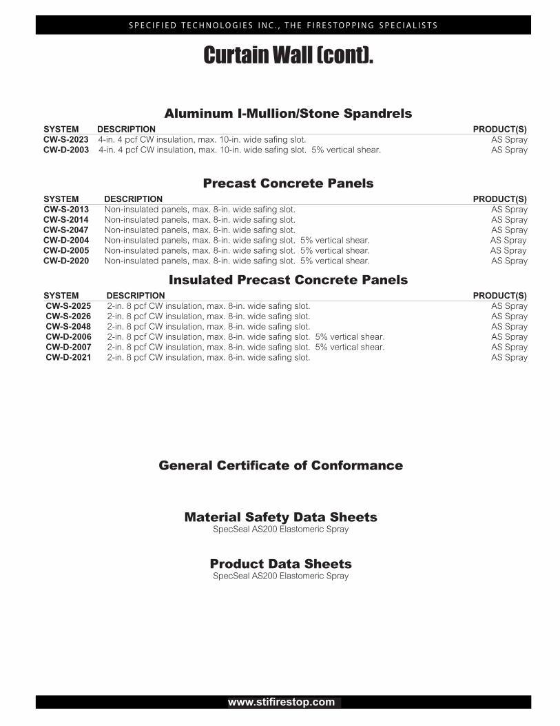
Curtain Wall (cont).
Aluminum I-Mullion/Stone SpandrelsSYSTEM DESCRIPTION PRODUCT(S)
CW-S-2023 4-in. 4 pcf CW insulation, max. 10-in. wide safing slot. AS Spray CW-D-2003 4-in. 4 pcf CW insulation, max. 10-in. wide safing slot. 5% vertical shear. AS Spray
Precast Concrete PanelsSYSTEM DESCRIPTION PRODUCT(S)
CW-S-2013 Non-insulated panels, max. 8-in. wide safing slot. AS Spray CW-S-2014 Non-insulated panels, max. 8-in. wide safing slot. AS Spray CW-S-2047 Non-insulated panels, max. 8-in. wide safing slot. AS Spray CW-D-2004 Non-insulated panels, max. 8-in. wide safing slot. 5% vertical shear. AS Spray CW-D-2005 Non-insulated panels, max. 8-in. wide safing slot. 5% vertical shear. AS Spray CW-D-2020 Non-insulated panels, max. 8-in. wide safing slot. 5% vertical shear. AS Spray
Insulated Precast Concrete PanelsSYSTEM DESCRIPTION PRODUCT(S)
CW-S-2025 2-in. 8 pcf CW insulation, max. 8-in. wide safing slot. AS Spray CW-S-2026 2-in. 8 pcf CW insulation, max. 8-in. wide safing slot. AS Spray CW-S-2048 2-in. 8 pcf CW insulation, max. 8-in. wide safing slot. AS Spray CW-D-2006 2-in. 8 pcf CW insulation, max. 8-in. wide safing slot. 5% vertical shear. AS Spray CW-D-2007 2-in. 8 pcf CW insulation, max. 8-in. wide safing slot. 5% vertical shear. AS Spray CW-D-2021 2-in. 8 pcf CW insulation, max. 8-in. wide safing slot. AS Spray
www.stifirestop.com
General Certificate of Conformance
Material Safety Data SheetsSpecSeal AS200 Elastomeric Spray
Product Data SheetsSpecSeal AS200 Elastomeric Spray
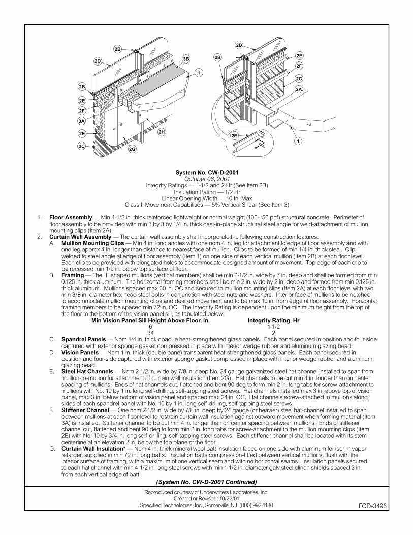
System No. CW-D-2001October 08, 2001
Integrity Ratings — 1-1/2 and 2 Hr (See Item 2B)Insulation Rating — 1/2 Hr
Linear Opening Width — 10 In. MaxClass II Movement Capabilities — 5% Vertical Shear (See Item 3)
1. Floor Assembly — Min 4-1/2 in. thick reinforced lightweight or normal weight (100-150 pcf) structural concrete. Perimeter of fl oor assembly to be provided with min 3 by 3 by 1/4 in. thick cast-in-place structural steel angle for weld-attachment of mullion mounting clips (Item 2A).
2. Curtain Wall Assembly — The curtain wall assembly shall incorporate the following construction features:A. Mullion Mounting Clips — Min 4 in. long angles with one nom 4 in. leg for attachment to edge of fl oor assembly and with
one leg approx 4 in. longer than distance to nearest face of mullion. Clips to be formed of min 1/4 in. thick steel. Clip welded to steel angle at edge of fl oor assembly (Item 1) on one side of each vertical mullion (Item 2B) at each fl oor level. Each clip to be provided with elongated holes to accommodate designed amount of movement. Top edge of each clip to be recessed min 1/2 in. below top surface of fl oor.
B. Framing — The “I” shaped mullions (vertical members) shall be min 2-1/2 in. wide by 7 in. deep and shall be formed from min 0.125 in. thick aluminum. The horizontal framing members shall be min 2 in. wide by 2 in. deep and formed from min 0.125 in. thick aluminum. Mullions spaced max 60 in. OC and secured to mullion mounting clips (Item 2A) at each fl oor level with two min 3/8 in. diameter hex head steel bolts in conjunction with steel nuts and washers. Interior face of mullions to be notched to accommodate mullion mounting clips and desired movement and to be max 10 in. from edge of fl oor assembly. Horizontal framing members to be spaced min 72 in. OC. The Integrity Rating is dependent upon the minimum height from the top of the fl oor to the bottom of the vision panel sill, as tabulated below:
Min Vision Panel Sill Height Above Floor, in. Integrity Rating, Hr 6 1-1/2 34 2
C. Spandrel Panels — Nom 1/4 in. thick opaque heat-strengthened glass panels. Each panel secured in position and four-side captured with exterior sponge gasket compressed in place with interior wedge rubber and aluminum glazing bead.
D. Vision Panels — Nom 1 in. thick (double pane) transparent heat-strengthened glass panels. Each panel secured in position and four-side captured with exterior sponge gasket compressed in place with interior wedge rubber and aluminum glazing bead.
E. Steel Hat Channels — Nom 2-1/2 in. wide by 7/8 in. deep No. 24 gauge galvanized steel hat channel installed to span from mullion-to-mullion for attachment of curtain wall insulation (Item 2G). Hat channels to be cut min 4 in. longer than on center spacing of mullions. Ends of hat channels cut, fl attened and bent 90 deg to form min 2 in. long tabs for screw-attachment to mullions with No. 10 by 1 in. long self-drilling, self-tapping steel screws. Hat channels installed max 3 in. above top of vision panel, max 3 in. below bottom of vision panel and spaced max 24 in. OC. Hat channels screw-attached to mullions along sides of each spandrel panel with No. 10 by 1 in. long self-drilling, self-tapping steel screws.
F. Stiffener Channel — One nom 2-1/2 in. wide by 7/8 in. deep by 24 gauge (or heavier) steel hat-channel installed to span between mullions at each fl oor level to restrain curtain wall insulation against outward movement when forming material (Item 3A) is installed. Stiffener channel to be cut min 4 in. longer than on center spacing between mullions. Ends of stiffener channel cut, fl attened and bent 90 deg to form min 2 in. long tabs for screw-attachment to the mullion mounting clips (Item 2E) with No. 10 by 3/4 in. long self-drilling, self-tapping steel screws. Each stiffener channel shall be located with its stem centerline at an elevation 2 in. below the top plane of the fl oor.
G. Curtain Wall Insulation* — Nom 4 in. thick mineral wool batt insulation faced on one side with aluminum foil/scrim vapor retarder, supplied in min 72 in. long batts. Insulation batts compression-fi tted between vertical mullions, fl ush with the interior surface of framing, with a maximum of one vertical seam and with no horizontal seams. Insulation panels secured to each hat channel with min 4-1/2 in. long steel screws with min 1-1/2 in. diameter galv steel clinch shields spaced 3 in. from each vertical edge of batt.
(System No. CW-D-2001 Continued)
Reproduced courtesy of Underwriters Laboratories, Inc.Created or Revised: 10/22/01
Specifi ed Technologies, Inc., Somerville, NJ (800) 992-1180 FOD-3496
THERMAFIBER LLC — FIRESPAN SS InsulationH. Mullion Insulation — Curtain Wall Insulation* — Min 8 in. wide strips cut from min 1 in. thick mineral wool batt insulation.
Framing covers to be centered over mullions and secured to the steel hat channels with min 5-1/2 in. long steel screws. Framing covers on mullions to abut the mineral wool batt safi ng material (Item 3A) above and below fl oor.
THERMAFIBER LLC — FIRESPAN Insulation3. Safi ng System — Max separation between edge of fl oor assembly and face of framing members (at time of installation) is 10 in.
The safi ng system is designed to accommodate vertical shear movement up to a max of 5 percent of its installed width. The safi ng system shall incorporate the following construction features:A. Forming Material* — Nom 4 pcf density mineral wool batt insulation. Batt sections cut to a 4 in. width and stacked to
a thickness which is min 20 percent greater than the width of the linear gap between the curtain wall insulation and the edge of the concrete fl oor slab. The forming material is compressed and inserted cut-edge-fi rst into linear gap such that its top surface is fl ush with the top surface of the fl oor assembly. A max of one tightly-butted seam is permitted between mullions. Additional piece of forming material to be friction-fi t into gap between batt sections above mullion mounting clip at each mullion location.
THERMAFIBER LLC — SAFB. Fill, Void or Cavity Material* — Min 1/8 in. wet thickness (min 1/16 in. dry thickness) of fi ll material spray-applied over
top of forming material and lapping min 1/2 in. onto the top surface of the fl oor and onto the curtain wall insulation and mullion covers.
SPECIFIED TECHNOLOGIES INC — SpecSeal AS200 Elastomeric Spray*Bearing the UL Classifi cation Marking
(System No. CW-D-2001 Continued)
Reproduced courtesy of Underwriters Laboratories, Inc.Created or Revised: 10/22/01
Specifi ed Technologies, Inc., Somerville, NJ (800) 992-1180 FOD-3496

System No. CW-D-2002October 08, 2001
Integrity Ratings — 1 1/2 and 2 Hr (See Item 2B) Insulation Rating — 1/2 Hr
Linear Opening Width — 10 In. MaxClass II Movement Capabilities — 5% Vertical Shear (See Item 3)
1. Floor Assembly — Min 4-1/2 in. thick reinforced lightweight or normal weight (100-150 pcf) structural concrete. Perimeter of fl oor assembly to be provided with min 3 by 3 by 1/4 in. thick cast-in-place structural steel angle for weld-attachment of mullion mounting clips (Item 2A).
2. Curtain Wall Assembly — The curtain wall assembly shall incorporate the following construction features:A. Mullion Mounting Clips — Min 4 in. long angles with one nom 4 in. leg for attachment to edge of fl oor assembly and with
one leg approx 4 in. longer than distance to nearest face of mullion. Clips to be formed of min 1/4 in. thick steel. Clip welded to steel angle at edge of fl oor assembly (Item 1) on one side of each vertical mullion (Item 2B) at each fl oor level. Each clip to be provided with elongated holes to accommodate designed amount of movement. Top edge of each clip to be recessed min 1/2 in. below top surface of fl oor.
B. Framing — The “I” shaped mullions (vertical members) shall be min 2-1/2 in. wide by 7 in. deep and shall be formed from min 0.125 in. thick aluminum. The horizontal framing members shall be min 2 in. wide by 2 in. deep and formed from min 0.125 in. thick aluminum. Mullions spaced max 60 in. OC and secured to mullion mounting clips (Item 2A) at each fl oor level with two min 3/8 in. diameter hex head steel bolts in conjunction with steel nuts and washers. Interior face of mullions to be notched to accommodate mullion mounting clips and desired movement and to be max 10 in. from edge of fl oor assembly. Horizontal framing members to be spaced min 72 in. OC. The Integrity Rating is dependent upon the minimum height from the top of the fl oor to the bottom of the vision panel sill, as tabulated below:
Min Vision Panel Sill Height Above Floor, in. Integrity Rating, Hr 6 1-1/2 34 2
C. Spandrel Panels — Nom 1/8 in. thick aluminum panels with 1/4 in. thick edges. Each panel secured in position and four-side captured with exterior sponge gasket compressed in place with interior wedge rubber and aluminum glazing bead.
D. Vision Panels — Nom 1 in. thick (double pane) transparent heat-strengthened glass panels. Each panel secured in position and four-side captured with exterior sponge gasket compressed in place with interior wedge rubber and aluminum glazing bead.
E. Steel Hat Channels — Nom 2-1/2 in. wide by 7/8 in. deep No. 24 gauge galvanized steel hat channel installed to span from mullion-to-mullion for attachment of curtain wall insulation (Item 2G). Hat channels to be cut min 4 in. longer than on center spacing of mullions. Ends of hat channels cut, fl attened and bent 90 deg to form min 2 in. long tabs for screw-attachment to mullions with No. 10 by 1 in. long self-drilling, self-tapping steel screws. Hat channels installed max 3 in. above top of vision panel, max 3 in. below bottom of vision panel and spaced max 24 in. OC. Hat channels screw-attached to mullions along sides of each spandrel panel with No. 10 by 1 in. long self-drilling, self-tapping steel screws.
F. Stiffener Channel — One nom 2-1/2 in. wide by 7/8 in. deep by 24 gauge (or heavier) steel hat-channel installed to span between mullions at each fl oor level to restrain curtain wall insulation against outward movement when forming material (Item 3A) is installed. Stiffener channel to be cut min 4 in. longer than on center spacing between mullions. Ends of stiffener channel cut, fl attened and bent 90 deg to form min 2 in. long tabs for screw-attachment to the mullion mounting clips (Item 2E) with No. 10 by 3/4 in. long self-drilling, self-tapping steel screws. Each stiffener channel shall be located with its stem centerline at an elevation 2 in. below the top plane of the fl oor.
G. Curtain Wall Insulation* — Nom 4 in. thick mineral wool batt insulation faced on one side with aluminum foil/scrim vapor retarder, supplied in min 72 in. long batts. Insulation batts compression-fi tted between vertical mullions, fl ush with the interior surface of framing, with a maximum of one vertical seam and with no horizontal seams. Insulation panels secured to each hat channel with min 4-1/2 in. long steel screws with min 1-1/2 in. diameter galv steel clinch shields spaced 3 in. from each vertical edge of batt.
(System No. CW-D-2002 Continued)
Reproduced courtesy of Underwriters Laboratories, Inc.Created or Revised: 10/22/01
Specifi ed Technologies, Inc., Somerville, NJ (800) 992-1180 FOD-3497

THERMAFIBER LLC — FIRESPAN SS InsulationH. Mullion Insulation — Curtain Wall Insulation* — Min 8 in. wide strips cut from min 1 in. thick mineral wool batt insulation.
Framing covers to be centered over mullions and secured to the steel hat channels with min 5-1/2 in. long steel screws. Framing covers on mullions to abut the mineral wool batt safi ng material (Item 3A) above and below fl oor.
THERMAFIBER LLC — FIRESPAN Insulation3. Safi ng System — Max separation between edge of fl oor assembly and face of framing members (at time of installation) is 10 in.
The safi ng system is designed to accommodate vertical shear movement up to a max of 5 percent of its installed width. The safi ng system shall incorporate the following construction features:A. Forming Material* — Nom 4 pcf density mineral wool batt insulation. Batt sections cut to a 4 in. width and stacked to
a thickness which is min 20 percent greater than the width of the linear gap between the curtain wall insulation and the edge of the concrete fl oor slab. The forming material is compressed and inserted cut-edge-fi rst into linear gap such that its top surface is fl ush with the top surface of the fl oor assembly. A max of one tightly-butted seam is permitted between mullions. Additional piece of forming material to be friction-fi t into gap between batt sections above mullion mounting clip at each mullion location.
THERMAFIBER LLC — SAFB. Fill, Void or Cavity Material* — Min 1/8 in. wet thickness (min 1/16 in. dry thickness) of fi ll material spray-applied over
top of forming material and lapping min 1/2 in. onto the top surface of the fl oor and onto the curtain wall insulation and mullion covers.
SPECIFIED TECHNOLOGIES INC — SpecSeal AS200 Elastomeric Spray*Bearing the UL Classifi cation Marking
(System No. CW-D-2002 Continued)
Reproduced courtesy of Underwriters Laboratories, Inc.Created or Revised: 10/22/01
Specifi ed Technologies, Inc., Somerville, NJ (800) 992-1180 FOD-3497
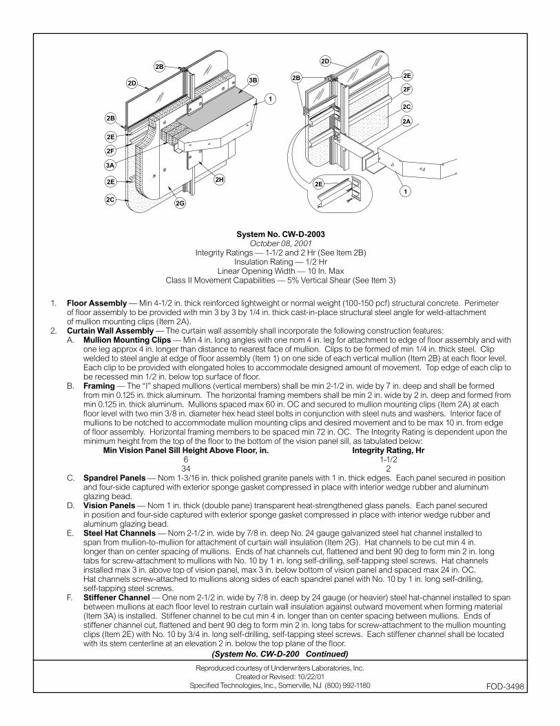
System No. CW-D-2003October 08, 2001
Integrity Ratings — 1-1/2 and 2 Hr (See Item 2B)Insulation Rating — 1/2 Hr
Linear Opening Width — 10 In. MaxClass II Movement Capabilities — 5% Vertical Shear (See Item 3)
1. Floor Assembly — Min 4-1/2 in. thick reinforced lightweight or normal weight (100-150 pcf) structural concrete. Perimeter of fl oor assembly to be provided with min 3 by 3 by 1/4 in. thick cast-in-place structural steel angle for weld-attachment of mullion mounting clips (Item 2A).
2. Curtain Wall Assembly — The curtain wall assembly shall incorporate the following construction features:A. Mullion Mounting Clips — Min 4 in. long angles with one nom 4 in. leg for attachment to edge of fl oor assembly and with
one leg approx 4 in. longer than distance to nearest face of mullion. Clips to be formed of min 1/4 in. thick steel. Clip welded to steel angle at edge of fl oor assembly (Item 1) on one side of each vertical mullion (Item 2B) at each fl oor level. Each clip to be provided with elongated holes to accommodate designed amount of movement. Top edge of each clip to be recessed min 1/2 in. below top surface of fl oor.
B. Framing — The “I” shaped mullions (vertical members) shall be min 2-1/2 in. wide by 7 in. deep and shall be formed from min 0.125 in. thick aluminum. The horizontal framing members shall be min 2 in. wide by 2 in. deep and formed from min 0.125 in. thick aluminum. Mullions spaced max 60 in. OC and secured to mullion mounting clips (Item 2A) at each fl oor level with two min 3/8 in. diameter hex head steel bolts in conjunction with steel nuts and washers. Interior face of mullions to be notched to accommodate mullion mounting clips and desired movement and to be max 10 in. from edge of fl oor assembly. Horizontal framing members to be spaced min 72 in. OC. The Integrity Rating is dependent upon the minimum height from the top of the fl oor to the bottom of the vision panel sill, as tabulated below:
Min Vision Panel Sill Height Above Floor, in. Integrity Rating, Hr 6 1-1/2 34 2
C. Spandrel Panels — Nom 1-3/16 in. thick polished granite panels with 1 in. thick edges. Each panel secured in position and four-side captured with exterior sponge gasket compressed in place with interior wedge rubber and aluminum glazing bead.
D. Vision Panels — Nom 1 in. thick (double pane) transparent heat-strengthened glass panels. Each panel secured in position and four-side captured with exterior sponge gasket compressed in place with interior wedge rubber and aluminum glazing bead.
E. Steel Hat Channels — Nom 2-1/2 in. wide by 7/8 in. deep No. 24 gauge galvanized steel hat channel installed to span from mullion-to-mullion for attachment of curtain wall insulation (Item 2G). Hat channels to be cut min 4 in. longer than on center spacing of mullions. Ends of hat channels cut, fl attened and bent 90 deg to form min 2 in. long tabs for screw-attachment to mullions with No. 10 by 1 in. long self-drilling, self-tapping steel screws. Hat channels installed max 3 in. above top of vision panel, max 3 in. below bottom of vision panel and spaced max 24 in. OC. Hat channels screw-attached to mullions along sides of each spandrel panel with No. 10 by 1 in. long self-drilling, self-tapping steel screws.
F. Stiffener Channel — One nom 2-1/2 in. wide by 7/8 in. deep by 24 gauge (or heavier) steel hat-channel installed to span between mullions at each fl oor level to restrain curtain wall insulation against outward movement when forming material (Item 3A) is installed. Stiffener channel to be cut min 4 in. longer than on center spacing between mullions. Ends of stiffener channel cut, fl attened and bent 90 deg to form min 2 in. long tabs for screw-attachment to the mullion mounting clips (Item 2E) with No. 10 by 3/4 in. long self-drilling, self-tapping steel screws. Each stiffener channel shall be located with its stem centerline at an elevation 2 in. below the top plane of the fl oor.
(System No. CW-D-2003 Continued)
Reproduced courtesy of Underwriters Laboratories, Inc.Created or Revised: 10/22/01
Specifi ed Technologies, Inc., Somerville, NJ (800) 992-1180 FOD-3498
G. Curtain Wall Insulation* — Nom 4 in. thick mineral wool batt insulation faced on one side with aluminum foil/scrim vapor retarder, supplied in min 72 in. long batts. Insulation batts compression-fi tted between vertical mullions, fl ush with the interior surface of framing, with a maximum of one vertical seam and with no horizontal seams. Insulation panels secured to each hat channel with min 4-1/2 in. long steel screws with min 1-1/2 in. diameter galv steel clinch shields spaced 3 in. from each vertical edge of batt.
THERMAFIBER LLC — FIRESPAN SS InsulationH. Mullion Insulation — Curtain Wall Insulation* — Min 8 in. wide strips cut from min 1 in. thick mineral wool batt
insulation. Framing covers to be centered over mullions and secured to the steel hat channels with min 5-1/2 in. long steel screws. Framing covers on mullions to abut the mineral wool batt safi ng material (Item 3A) above and below fl oor.
THERMAFIBER LLC — FIRESPAN Insulation3. Safi ng System — Max separation between edge of fl oor assembly and face of framing members (at time of installation) is
10 in. The safi ng system is designed to accommodate vertical shear movement up to a max of 5 percent of its installed width. The safi ng system shall incorporate the following construction features:A. Forming Material* — Nom 4 pcf density mineral wool batt insulation. Batt sections cut to a 4 in. width and stacked
to a thickness which is min 20 percent greater than the width of the linear gap between the curtain wall insulation and the edge of the concrete fl oor slab. The forming material is compressed and inserted cut-edge-fi rst into linear gap such that its top surface is fl ush with the top surface of the fl oor assembly. A max of one tightly-butted seam is permitted between mullions. Additional piece of forming material to be friction-fi t into gap between batt sections above mullion mounting clip at each mullion location.
THERMAFIBER LLC — SAFB. Fill, Void or Cavity Material* — Min 1/8 in. wet thickness (min 1/16 in. dry thickness) of fi ll material spray-applied over
top of forming material and lapping min 1/2 in. onto the top surface of the fl oor and onto the curtain wall insulation and mullion covers.
SPECIFIED TECHNOLOGIES INC — SpecSeal AS200 Elastomeric Spray*Bearing the UL Classifi cation Marking
(System No. CW-D-2003 Continued)
Reproduced courtesy of Underwriters Laboratories, Inc.Created or Revised: 10/22/01
Specifi ed Technologies, Inc., Somerville, NJ (800) 992-1180 FOD-3498

System No. CW-D-2004July 27, 2001
Integrity Rating — 2 HrInsulation Rating — 1/4 Hr
Linear Opening Width — 8 in. MaxClass II Movement Capabilities — 5% Vertical Shear (See Item 3)
1. Floor Assembly — Min 4-1/2 in. thick steel-reinforced lightweight or normal weight (100-150 pcf) structural concrete. Floor assembly to be supported at perimeter edges by spandrel beams having a Restrained or Unrestrained Beam Rating of 2 hr.
2. Curtain Wall Assembly — The curtain wall assembly shall incorporate the following construction features:A. Spandrel Panels — Min 72 in. high by min 4 in. thick steel-reinforced lightweight or normal weight (100-150 pcf) structural
concrete spandrel panels. Wall may also consist of min 4 in. thick steel-reinforced lightweight or normal weight concrete tilt-up panels with a min 72 in. vertical separation between window openings. Panels provided with steel dead load anchors welded to steel reinforcing bars embedded in the concrete for attachment to the steel columns and spandrel beams. Panels also provided with steel lateral anchors or braces. The dead load anchors which are located in the linear gap between the concrete fl oor slab and the spandrel panel or tilt-up panel are to be spaced max 72 in. OC. The top of the dead load anchor is to be recessed min 1/2 in. from top surface of fl oor.
B. Joint System — (Not Shown) — Vertical joints between spandrel panels or tilt-up panels to be protected using Joint System No. WW-S-0038.
C. Framed Window — Metal framed window with nom 1/4 in. thick heat-strengthened glass. Sill of window to be min 34 in. above top of fl oor.
3. Safi ng System — Max separation between edge of fl oor assembly and concrete spandrel or tilt-up panel is 8 in. The safi ng system is designed to accommodate vertical shear movement between dead load anchors up to a max of 5 percent of its installed width. The safi ng system shall incorporate the following construction features:A. Forming Material* — Nom 4 in. thick mineral wool batt safi ng material to be installed between the concrete spandrel or tilt-up
panel and the edge of the concrete fl oor slab. Safi ng material to be cut to a min 4-1/2 in. width and stacked to a thickness which is at least 25 percent greater than the width of the linear gap between the concrete spandrel or tilt-up panel and the edge of the concrete fl oor slab. The safi ng material is compressed and inserted cut-edge-fi rst into the linear gap such that its top surface is fl ush with the top surface of the fl oor assembly. A max of one tightly-butted seam is permitted between dead load anchors. An additional min 1/2 in. thick piece of mineral wool batt safi ng material to be installed to cover top surface of each dead load anchor.
ROXUL INC — SAFEB. Fill, Void or Cavity Material* — Min 1/8 in. wet thickness of fi ll material spray-applied over top of forming material and lapping
min 1/2 in. onto the top surface of the concrete fl oor and onto the concrete spandrel panel or tilt-up panel.SPECIFIED TECHNOLOGIES INC — SpecSeal AS200 Elastomeric Spray
*Bearing the UL Classifi cation Mark
Reproduced courtesy of Underwriters Laboratories, Inc.Created or Revised: 10/22/01
Specifi ed Technologies, Inc., Somerville, NJ (800) 992-1180 FOD-3495
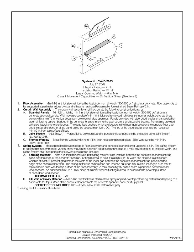
System No. CW-D-2005July 27, 2001
Integrity Rating — 2 HrInsulation Rating — 1/4 Hr
Linear Opening Width — 8 in. MaxClass II Movement Capabilities — 5% Vertical Shear (See Item 3)
1. Floor Assembly — Min 4-1/2 in. thick steel-reinforced lightweight or normal weight (100-150 pcf) structural concrete. Floor assembly to be supported at perimeter edges by spandrel beams having a Restrained or Unrestrained Beam Rating of 2 hr.
2. Curtain Wall Assembly — The curtain wall assembly shall incorporate the following construction features:A. Spandrel Panels — Min 72 in. high by min 4 in. thick steel-reinforced lightweight or normal weight (100-150 pcf) structural
concrete spandrel panels. Wall may also consist of min 4 in. thick steel-reinforced lightweight or normal weight concrete tilt-up panels with a min 72 in. vertical separation between window openings. Panels provided with steel dead load anchors welded to steel reinforcing bars embedded in the concrete for attachment to the steel columns and spandrel beams. Panels also provided with steel lateral anchors or braces. The dead load anchors which are located in the linear gap between the concrete fl oor slab and the spandrel panel or tilt-up panel are to be spaced max 72 in. OC. The top of the dead load anchor is to be recessed min 1/2 in. from top surface of fl oor.
B. Joint System — (Not Shown) — Vertical joints between spandrel panels or tilt-up panels to be protected using Joint System No. WW-S-0038.
C. Framed Window — Metal framed window with nom 1/4 in. thick heat-strengthened glass. Sill of window to be min 34 in. above top of fl oor.
3. Safi ng System — Max separation between edge of fl oor assembly and concrete spandrel or tilt-up panel is 8 in. The safi ng system is designed to accommodate vertical shear movement between dead load anchors up to a max of 5 percent of its installed width. The safi ng system shall incorporate the following construction features:A. Forming Material* — Nom 4 in. thick mineral wool batt safi ng material to be installed between the concrete spandrel or tilt-up
panel and the edge of the concrete fl oor slab. Safi ng material to be cut to a min 4-1/2 in. width and stacked to a thickness which is at least 25 percent greater than the width of the linear gap between the concrete spandrel or tilt-up panel and the edge of the concrete fl oor slab. The safi ng material is compressed and inserted cut-edge-fi rst into the linear gap such that its top surface is fl ush with the top surface of the fl oor assembly. A max of one tightly-butted seam is permitted between dead load anchors. An additional min 1/2 in. thick piece of mineral wool batt safi ng material to be installed to cover top surface of each dead load anchor.
THERMAFIBER LLC — SAFB. Fill, Void or Cavity Material* — Min 1/8 in. wet thickness of fi ll material spray-applied over top of forming material and lapping min
1/2 in. onto the top surface of the concrete fl oor and onto the concrete spandrel panel or tilt-up panel.SPECIFIED TECHNOLOGIES INC — SpecSeal AS200 Elastomeric Spray
*Bearing the UL Classifi cation Mark
Reproduced courtesy of Underwriters Laboratories, Inc.Created or Revised: 10/22/01
Specifi ed Technologies, Inc., Somerville, NJ (800) 992-1180 FOD-3494
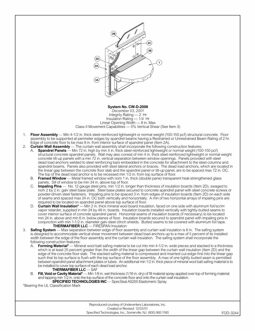
System No. CW-D-2006December 03, 2001
Integrity Rating — 2 HrInsulation Rating — 1/4 Hr
Linear Opening Width — 8 in. MaxClass II Movement Capabilities — 5% Vertical Shear (See Item 3)
1. Floor Assembly — Min 4-1/2 in. thick steel-reinforced lightweight or normal weight (100-150 pcf) structural concrete. Floor assembly to be supported at perimeter edges by spandrel beams having a Restrained or Unrestrained Beam Rating of 2 hr. Edge of concrete fl oor to be max 8 in. from interior surface of spandrel panel (Item 2A).
2. Curtain Wall Assembly — The curtain wall assembly shall incorporate the following construction features:A. Spandrel Panels — Min 72 in. high by min 4 in. thick steel-reinforced lightweight or normal weight (100-150 pcf)
structural concrete spandrel panels. Wall may also consist of min 4 in. thick steel-reinforced lightweight or normal weight concrete tilt-up panels with a min 72 in. vertical separation between window openings. Panels provided with steel dead load anchors welded to steel reinforcing bars embedded in the concrete for attachment to the steel columns and spandrel beams. Panels also provided with steel lateral anchors or braces. The dead load anchors, which are located in the linear gap between the concrete fl oor slab and the spandrel panel or tilt-up panel, are to be spaced max 72 in. OC. The top of the dead load anchor is to be recessed min 1/2 in. from top surface of fl oor.
B. Framed Window — Metal framed window with nom 1 in. thick (double pane) transparent heat-strengthened glass panels. Sill of window to be min 34 in. above top of fl oor.
C. Impaling Pins — No. 12 gauge steel pins, min 1/2 in. longer than thickness of insulation boards (Item 2D), swaged to nom 2 by 2 in. galv steel base plate. Steel base plates secured to concrete spandrel panel with steel concrete screws or powder-driven steel fasteners. Impaling pins to be spaced 3 in. from edges of insulation boards (Item 2D) on each side of seams and spaced max 24 in. OC both vertically and horizontally. A min of two horizontal arrays of impaling pins are required to be located on spandrel panel above top surface of fl oor.
D. Curtain Wall Insulation* — Min 2 in. thick mineral wool board insulation, faced on one side with aluminum foil/scrim vapor retarder, supplied in min 24 by 48 in. boards. Insulation boards installed vertically with tightly-butted seams to cover interior surface of concrete spandrel panel. Horizontal seams of insulation boards (if necessary) to be located min 24 in. above and min 6 in. below planes of fl oor. Insulation boards secured to spandrel panel with impaling pins in conjunction with min 1-1/2 in. diameter galv steel clinch shields. Butted seams to be covered with aluminum foil tape.
THERMAFIBER LLC — FIRESPAN Insulation3. Safi ng System — Max separation between edge of fl oor assembly and curtain wall insulation is 6 in. The safi ng system
is designed to accommodate vertical shear movement between dead load anchors up to a max of 5 percent of its installed width between the edge of the fl oor assembly and the curtain wall insulation. The safi ng system shall incorporate the following construction features:A. Forming Material* — Mineral wool batt safi ng material to be cut into min 4-1/2 in. wide pieces and stacked to a thickness
which is at least 25 percent greater than the width of the linear gap between the curtain wall insulation (Item 2D) and the edge of the concrete fl oor slab. The stacked safi ng material is compressed and inserted cut-edge-fi rst into the linear gap such that its top surface is fl ush with the top surface of the fl oor assembly. A max of one tightly butted seam is permitted between spandrel panel attachment plates or tubes. An additional min 1/2 in. thick piece of mineral wool batt safi ng material is to be installed to cover top surface of each dead load anchor.
THERMAFIBER LLC — SAFB. Fill, Void or Cavity Material* — Min 1/8 in. wet thickness (1/16 in. dry) of fi ll material spray-applied over top of forming material
and lapping min 1/2 in. onto the top surface of the concrete fl oor and onto the curtain wall insulation. SPECIFIED TECHNOLOGIES INC — SpecSeal AS200 Elastomeric Spray
*Bearing the UL Classifi cation Mark
Reproduced courtesy of Underwriters Laboratories, Inc.Created or Revised: 12/03/01
Specifi ed Technologies, Inc., Somerville, NJ (800) 992-1180 FOD-3244
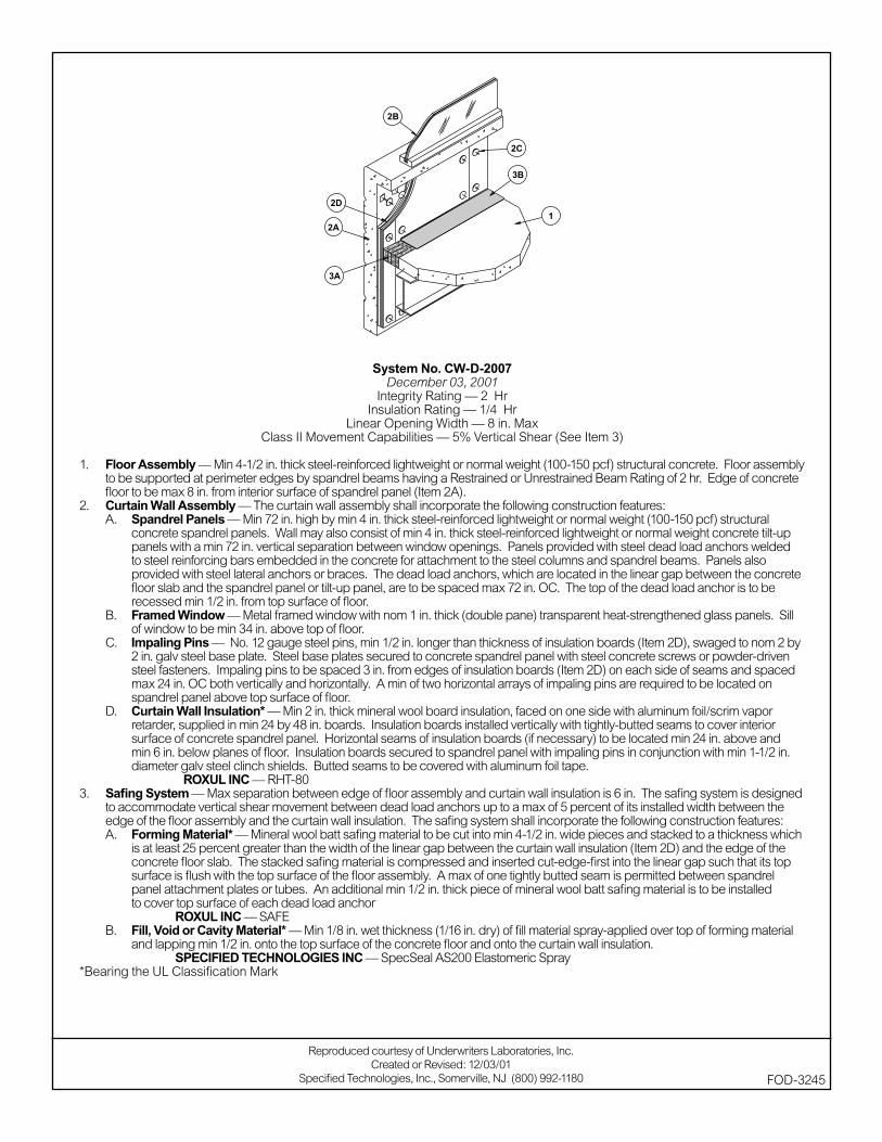
System No. CW-D-2007December 03, 2001
Integrity Rating — 2 HrInsulation Rating — 1/4 Hr
Linear Opening Width — 8 in. MaxClass II Movement Capabilities — 5% Vertical Shear (See Item 3)
1. Floor Assembly — Min 4-1/2 in. thick steel-reinforced lightweight or normal weight (100-150 pcf) structural concrete. Floor assembly to be supported at perimeter edges by spandrel beams having a Restrained or Unrestrained Beam Rating of 2 hr. Edge of concrete fl oor to be max 8 in. from interior surface of spandrel panel (Item 2A).
2. Curtain Wall Assembly — The curtain wall assembly shall incorporate the following construction features:A. Spandrel Panels — Min 72 in. high by min 4 in. thick steel-reinforced lightweight or normal weight (100-150 pcf) structural
concrete spandrel panels. Wall may also consist of min 4 in. thick steel-reinforced lightweight or normal weight concrete tilt-up panels with a min 72 in. vertical separation between window openings. Panels provided with steel dead load anchors welded to steel reinforcing bars embedded in the concrete for attachment to the steel columns and spandrel beams. Panels also provided with steel lateral anchors or braces. The dead load anchors, which are located in the linear gap between the concrete fl oor slab and the spandrel panel or tilt-up panel, are to be spaced max 72 in. OC. The top of the dead load anchor is to be recessed min 1/2 in. from top surface of fl oor.
B. Framed Window — Metal framed window with nom 1 in. thick (double pane) transparent heat-strengthened glass panels. Sill of window to be min 34 in. above top of fl oor.
C. Impaling Pins — No. 12 gauge steel pins, min 1/2 in. longer than thickness of insulation boards (Item 2D), swaged to nom 2 by 2 in. galv steel base plate. Steel base plates secured to concrete spandrel panel with steel concrete screws or powder-driven steel fasteners. Impaling pins to be spaced 3 in. from edges of insulation boards (Item 2D) on each side of seams and spaced max 24 in. OC both vertically and horizontally. A min of two horizontal arrays of impaling pins are required to be located on spandrel panel above top surface of fl oor.
D. Curtain Wall Insulation* — Min 2 in. thick mineral wool board insulation, faced on one side with aluminum foil/scrim vapor retarder, supplied in min 24 by 48 in. boards. Insulation boards installed vertically with tightly-butted seams to cover interior surface of concrete spandrel panel. Horizontal seams of insulation boards (if necessary) to be located min 24 in. above and min 6 in. below planes of fl oor. Insulation boards secured to spandrel panel with impaling pins in conjunction with min 1-1/2 in. diameter galv steel clinch shields. Butted seams to be covered with aluminum foil tape.
ROXUL INC — RHT-803. Safi ng System — Max separation between edge of fl oor assembly and curtain wall insulation is 6 in. The safi ng system is designed
to accommodate vertical shear movement between dead load anchors up to a max of 5 percent of its installed width between the edge of the fl oor assembly and the curtain wall insulation. The safi ng system shall incorporate the following construction features:A. Forming Material* — Mineral wool batt safi ng material to be cut into min 4-1/2 in. wide pieces and stacked to a thickness which
is at least 25 percent greater than the width of the linear gap between the curtain wall insulation (Item 2D) and the edge of the concrete fl oor slab. The stacked safi ng material is compressed and inserted cut-edge-fi rst into the linear gap such that its top surface is fl ush with the top surface of the fl oor assembly. A max of one tightly butted seam is permitted between spandrel panel attachment plates or tubes. An additional min 1/2 in. thick piece of mineral wool batt safi ng material is to be installed to cover top surface of each dead load anchor
ROXUL INC — SAFEB. Fill, Void or Cavity Material* — Min 1/8 in. wet thickness (1/16 in. dry) of fi ll material spray-applied over top of forming material
and lapping min 1/2 in. onto the top surface of the concrete fl oor and onto the curtain wall insulation. SPECIFIED TECHNOLOGIES INC — SpecSeal AS200 Elastomeric Spray
*Bearing the UL Classifi cation Mark
Reproduced courtesy of Underwriters Laboratories, Inc.Created or Revised: 12/03/01
Specifi ed Technologies, Inc., Somerville, NJ (800) 992-1180 FOD-3245
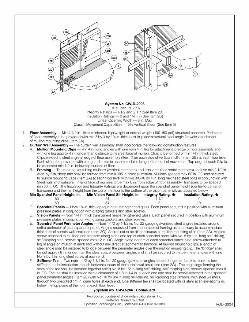
System No. CW-D-2008November 30, 2001
Integrity Ratings — 1-1/2 and 2 Hr (See Item 2B)Insulation Ratings — 0 and 1/4 Hr (See Item 2B)
Linear Opening Width — 8 in. MaxClass II Movement Capabilities — 5% Vertical Shear (See Item 3)
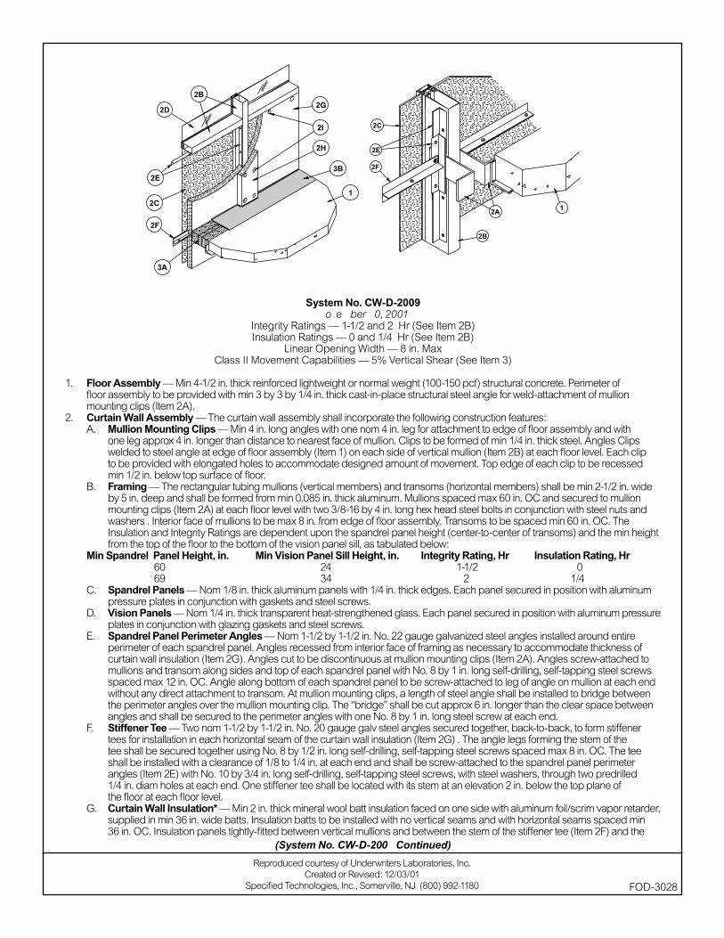
1. Floor Assembly — Min 4-1/2 in . thick reinforced lightweight or normal weight (100-150 pcf) structural concrete. Perimeter of fl oor assembly to be provided with min 3 by 3 by 1/4 in. thick cast-in-place structural steel angle for weld-attachment of mullion mounting clips (Item 2A).
2. Curtain Wall Assembly — The curtain wall assembly shall incorporate the following construction features:A. Mullion Mounting Clips — Min 4 in. long angles with one nom 4 in. leg for attachment to edge of fl oor assembly and
with one leg approx 4 in. longer than distance to nearest face of mullion. Clips to be formed of min 1/4 in. thick steel. Clips welded to steel angle at edge of fl oor assembly (Item 1) on each side of vertical mullion (Item 2B) at each fl oor level. Each clip to be provided with elongated holes to accommodate designed amount of movement. Top edge of each Clip to be recessed min 1/2 in. below top surface of fl oor.
B. Framing — The rectangular tubing mullions (vertical members) and transoms (horizontal members) shall be min 2-1/2 in. wide by 5 in. deep and shall be formed from min 0.085 in. thick aluminum. Mullions spaced max 60 in. OC and secured to mullion mounting Clips (Item 2A) at each fl oor level with two 3/8-16 by 4 in. long hex head steel bolts in conjunction with Steel nuts and wahsers . Interior face of mullions to be max 8 in. from edge of fl oor assembly. Transoms to be spaced min 60 in. OC. The Insulation and Integrity Ratings are dependent upon the spandrel panel height (center-to-center of transoms) and the min height from the top of the fl oor to the bottom of the vision panel sill, as tabulated below
Min Spandrel Panel Height, in. Min Vision Panel Sill Height, in. Integrity Rating, Hr Insulation Rating, Hr 60 24 1-1/2 0 69 34 2 1/4C. Spandrel Panels — Nom 1/4 in. thick opaque heat-strengthened glass. Each panel secured in position with aluminum
pressure plates in conjunction with glazing gaskets and steel screws.D. Vision Panels — Nom 1/4 in. thick transparent heat-strengthened glass. Each panel secured in position with aluminum
pressure plates in conjunction with glazing gaskets and steel screws.E. Spandrel Panel Perimeter Angles — Nom 1-1/2 by 1-1/2 in. No. 22 gauge galvanized steel angles installed around
entire perimeter of each spandrel panel. Angles recessed from interior face of framing as necessary to accommodate thickness of curtain wall insulation (Item 2G). Angles cut to be discontinuous at mullion mounting clips (Item 2A). Angles screw-attached to mullions and transom along sides and top of each spandrel panel with No. 8 by 1 in. long self-drilling, self-tapping steel screws spaced max 12 in. OC. Angle along bottom of each spandrel panel to be screw-attached to leg of angle on mullion at each end without any direct attachment to transom. At mullion mounting clips, a length of steel angle shall be installed to bridge between the perimeter angles over the mullion mounting clip. The “bridge” shall be cut approx 6 in. longer than the clear space between angles and shall be secured to the perimeter angles with one No. 8 by 1 in. long steel screw at each end.
F. Stiffener Tee — Two nom 1-1/2 by 1-1/2 in. No. 20 gauge galv steel angles secured together, back-to-back, to form stiffener tee for installation in each horizontal seam of the curtain wall insulation (Item 2G) . The angle legs forming the stem of the tee shall be secured together using No. 8 by 1/2 in. long self-drilling, self-tapping steel screws spaced max 8 in. OC. The tee shall be installed with a clearance of 1/8 to 1/4 in. at each end and shall be screw-attached to the spandrel panel perimeter angles (Item 2E) with No. 10 by 3/4 in. long self-drilling, self-tapping steel screws, with steel washers, through two predrilled 1/4 in. diam holes at each end. One stiffener tee shall be located with its stem at an elevation 2 in. below the top plane of the fl oor at each fl oor level.
Reproduced courtesy of Underwriters Laboratories, Inc.Created or Revised: 12/03/01
Specifi ed Technologies, Inc., Somerville, NJ (800) 992-1180 FOD-3004
(System No. CW-D-2008 Continued)
G. Curtain Wall Insulation* — Min 2 in. thick mineral wool batt insulation faced on one side with aluminum foil/scrim vapor retarder, supplied in min 36 in. wide batts. Insulation batts to be installed with no vertical seams and with horizontal seams spaced min 36 in. OC. Insulation panels tightly-fi tted between vertical mullions and between the stem of the stiffener tee (Item 2F) and the transom, fl ush with the interior surface of framing. Insulation panels secured to spandrel panel perimeter angles and to each stiffener tee with cup head weld pins (Item 2I) spaced max 12 in. OC. The horizontal seam between insulation panels shall be located 2 in. below the top plane of the fl oor at each fl oor level.
THERMAFIBER LLC — FIRESPAN Insulation H. Framing Covers — Curtain Wall Insulation* Min 8 in. wide strips cut from the same min 2 in. thick mineral wool batt
insulation used for the curtain wall insulation (Item 2G). Framing covers to be centered over mullions and secured to the spandrel panel perimeter angles with cup head weld pins (Item 2I) spaced max 12 in. OC. Where more than one spandrel panel occurs between vertically separated vision panels, the horizontal transom between spandrel panels shall also be covered with an 8 in. wide framing cover in the same manner as on the vertical mullions. Framing covers on mullions to abut the mineral wool batt safi ng material (Item 3A) above and below fl oor.
THERMAFIBER LLC — FIRESPAN Insulation I. Weld Pin — No. 12 gauge galv steel weld pin with nom 1-3/16 in. diam galv steel cup head. Cup head weld pins
provided in two lengths. One length to be equal to thickness of curtain wall insulation (Item 2G) and second length to be equal to thickness of curtain wall insulation plus thickness of framing cover (Item 2H). Cup head weld pins inserted through curtain wall insulation and mullion covers and welded to spandrel panel perimeter angles max 12 in. OC.
3. Safi ng System — Max separation between edge of fl oor assembly and face of framing members (at time of installation) is 8 in. The safi ng system is designed to accommodate vertical shear movement up to a max of 5 percent of its installed width. The safi ng system shall incorporate the following construction features:A. Forming Material* — Nom 4 pcf density mineral wool batt insulation. Batt sections cut to a min 4-1/2 in. width and
stacked to a thickness which is min 20 percent greater than the width of linear gap between the curtain wall insulation and the edge of the concrete fl oor slab. The forming material is compressed and inserted cut-edge-fi rst into linear gap such that its top surface is fl ush with the top surface of the fl oor assembly. A max of one tightly-butted seam is permitted between mullions. Additional pieces of forming material to be friction-fi t into spaces between mullion mounting clips at each mullion location.
THERMAFIBER LLC — SAFB. Fill, Void or Cavity Material* — Min 1/8 in. wet thickness (min 1/16 in. dry thickness) of fi ll material spray-applied over
top of forming material and lapping min 1/2 in. onto the top surface of the fl oor and onto the curtain wall insulation and framing covers.
SPECIFIED TECHNOLOGIES INC — SpecSeal AS200 Elastomeric Spray*Bearing the UL Classifi cation Mark
(System No. CW-D-2008 Continued)
FOD-3004
Reproduced courtesy of Underwriters Laboratories, Inc.Created or Revised: 12/03/01
Specifi ed Technologies, Inc., Somerville, NJ (800) 992-1180
System No. CW-D-2009November 30, 2001
Integrity Ratings — 1-1/2 and 2 Hr (See Item 2B)Insulation Ratings — 0 and 1/4 Hr (See Item 2B)
Linear Opening Width — 8 in. MaxClass II Movement Capabilities — 5% Vertical Shear (See Item 3)
1. Floor Assembly — Min 4-1/2 in. thick reinforced lightweight or normal weight (100-150 pcf) structural concrete. Perimeter of fl oor assembly to be provided with min 3 by 3 by 1/4 in. thick cast-in-place structural steel angle for weld-attachment of mullion mounting clips (Item 2A).
2. Curtain Wall Assembly — The curtain wall assembly shall incorporate the following construction features:A. Mullion Mounting Clips — Min 4 in. long angles with one nom 4 in. leg for attachment to edge of fl oor assembly and with
one leg approx 4 in. longer than distance to nearest face of mullion. Clips to be formed of min 1/4 in. thick steel. Angles Clips welded to steel angle at edge of fl oor assembly (Item 1) on each side of vertical mullion (Item 2B) at each fl oor level. Each clip to be provided with elongated holes to accommodate designed amount of movement. Top edge of each clip to be recessed min 1/2 in. below top surface of fl oor.
B. Framing — The rectangular tubing mullions (vertical members) and transoms (horizontal members) shall be min 2-1/2 in. wide by 5 in. deep and shall be formed from min 0.085 in. thick aluminum. Mullions spaced max 60 in. OC and secured to mullion mounting clips (Item 2A) at each fl oor level with two 3/8-16 by 4 in. long hex head steel bolts in conjunction with steel nuts and washers . Interior face of mullions to be max 8 in. from edge of fl oor assembly. Transoms to be spaced min 60 in. OC. The Insulation and Integrity Ratings are dependent upon the spandrel panel height (center-to-center of transoms) and the min height from the top of the fl oor to the bottom of the vision panel sill, as tabulated below:
Min Spandrel Panel Height, in. Min Vision Panel Sill Height, in. Integrity Rating, Hr Insulation Rating, Hr 60 24 1-1/2 0 69 34 2 1/4C. Spandrel Panels — Nom 1/8 in. thick aluminum panels with 1/4 in. thick edges. Each panel secured in position with aluminum
pressure plates in conjunction with gaskets and steel screws.D. Vision Panels — Nom 1/4 in. thick transparent heat-strengthened glass. Each panel secured in position with aluminum pressure
plates in conjunction with glazing gaskets and steel screws.E. Spandrel Panel Perimeter Angles — Nom 1-1/2 by 1-1/2 in. No. 22 gauge galvanized steel angles installed around entire
perimeter of each spandrel panel. Angles recessed from interior face of framing as necessary to accommodate thickness of curtain wall insulation (Item 2G). Angles cut to be discontinuous at mullion mounting clips (Item 2A). Angles screw-attached to mullions and transom along sides and top of each spandrel panel with No. 8 by 1 in. long self-drilling, self-tapping steel screws spaced max 12 in. OC. Angle along bottom of each spandrel panel to be screw-attached to leg of angle on mullion at each end without any direct attachment to transom. At mullion mounting clips, a length of steel angle shall be installed to bridge between the perimeter angles over the mullion mounting clip. The “bridge” shall be cut approx 6 in. longer than the clear space between angles and shall be secured to the perimeter angles with one No. 8 by 1 in. long steel screw at each end.
F. Stiffener Tee — Two nom 1-1/2 by 1-1/2 in. No. 20 gauge galv steel angles secured together, back-to-back, to form stiffener tees for installation in each horizontal seam of the curtain wall insulation (Item 2G) . The angle legs forming the stem of the tee shall be secured together using No. 8 by 1/2 in. long self-drilling, self-tapping steel screws spaced max 8 in. OC. The tee shall be installed with a clearance of 1/8 to 1/4 in. at each end and shall be screw-attached to the spandrel panel perimeter angles (Item 2E) with No. 10 by 3/4 in. long self-drilling, self-tapping steel screws, with steel washers, through two predrilled 1/4 in. diam holes at each end. One stiffener tee shall be located with its stem at an elevation 2 in. below the top plane of the fl oor at each fl oor level.
G. Curtain Wall Insulation* — Min 2 in. thick mineral wool batt insulation faced on one side with aluminum foil/scrim vapor retarder, supplied in min 36 in. wide batts. Insulation batts to be installed with no vertical seams and with horizontal seams spaced min 36 in. OC. Insulation panels tightly-fi tted between vertical mullions and between the stem of the stiffener tee (Item 2F) and the
Reproduced courtesy of Underwriters Laboratories, Inc.Created or Revised: 12/03/01
Specifi ed Technologies, Inc., Somerville, NJ (800) 992-1180 FOD-3028
(System No. CW-D-2009 Continued)
transom, fl ush with the interior surface of framing. Insulation panels secured to spandrel panel perimeter angles and to each stiffener tee with cup head weld pins (Item 2I) spaced max 12 in OC. The horizontal seam between insulation panels shall be located 2 in. below the top plane of the fl oor at each fl oor level.
THERMAFIBER LLC — FIRESPAN InsulationH. Framing Covers — Curtain Wall Insulation* Min 8 in. wide strips cut from the same min 2 in. thick mineral wool batt insulation
used for the curtain wall insulation (Item 2G ). Framing covers to be centered over mullions and secured to the spandrel panel perimeter angles with cup head weld pins (Item 2I) spaced max 12 in. OC. Where more than one spandrel panel occurs between vertically separated vision panels, the horizontal transom between spandrel panels shall also be covered with an 8 in. wide framing cover in the same manner as on the vertical mullions. Framing covers on mullions to abut the mineral wool batt safi ng material (Item 3A) above and below fl oor.
THERMAFIBER LLC — FIRESPAN InsulationI. Weld Pin — No. 12 gauge galv steel weld pin with nom 1-3/16 in. diam galv steel cup head. Cup head weld pins provided in
two lengths. One length to be equal to thickness of curtain wall insulation (Item 2G) and second length to be equal to thickness of curtain wall insulation plus thickness of framing cover (Item 2H). Cup head weld pins inserted through curtain wall insulation and mullion covers and welded to spandrel panel perimeter angles max 12 in. OC.
3. Safi ng System — Max separation between edge of fl oor assembly and face of framing members (at time of installation) is 8 in. The safi ng system is designed to accommodate vertical shear movement up to a max of 5 percent of its installed width. The safi ng system shall incorporate the following construction features:A. Forming Material* — Nom 4 pcf density mineral wool batt insulation. Batt sections cut to a min 4-1/2 in. width and stacked to
a thickness which is min 20 percent greater than the width of linear gap between the curtain wall insulation and the edge of the concrete fl oor slab. The forming material is compressed and inserted cut-edge-fi rst into linear gap such that its top surface is fl ush with the top surface of the fl oor assembly. A max of one tightly-butted seam is permitted between mullions. Additional pieces of forming material to be friction-fi t into spaces between mullion mounting clips at each mullion location.
THERMAFIBER LLC — SAFB. Fill, Void or Cavity Material* — Min 1/8 in. wet thickness (min 1/16 in. dry thickness) of fi ll material spray- applied over
top of forming material and lapping min 1/2 in. onto the top surface of the fl oor and onto the curtain wall insulation and framing covers.
SPECIFIED TECHNOLOGIES INC — SpecSeal AS200 Elastomeric Spray.*Bearing the UL Classifi cation Mark
(System No. CW-D-2009 Continued)
FOD-3028
Reproduced courtesy of Underwriters Laboratories, Inc.Created or Revised: 12/03/01
Specifi ed Technologies, Inc., Somerville, NJ (800) 992-1180
System No. CW-D-2010November 30, 2001
Integrity Ratings — 1-1/2 and 2 Hr (See Item 2B)Insulation Ratings — 0 and 1/4 Hr (See Item 2B)
Linear Opening Width — 8 in. MaxClass II Movement Capabilities — 5% Vertical Shear (See Item 3)
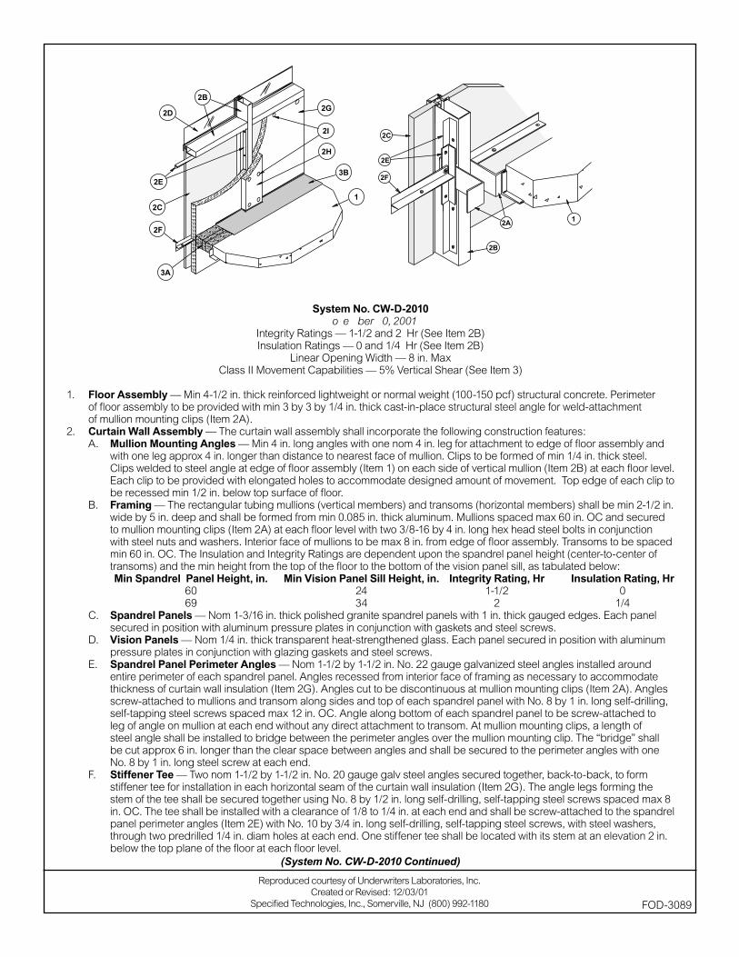
1. Floor Assembly — Min 4-1/2 in. thick reinforced lightweight or normal weight (100-150 pcf) structural concrete. Perimeter of fl oor assembly to be provided with min 3 by 3 by 1/4 in. thick cast-in-place structural steel angle for weld-attachment of mullion mounting clips (Item 2A).
2. Curtain Wall Assembly — The curtain wall assembly shall incorporate the following construction features:A. Mullion Mounting Angles — Min 4 in. long angles with one nom 4 in. leg for attachment to edge of fl oor assembly and
with one leg approx 4 in. longer than distance to nearest face of mullion. Clips to be formed of min 1/4 in. thick steel. Clips welded to steel angle at edge of fl oor assembly (Item 1) on each side of vertical mullion (Item 2B) at each fl oor level. Each clip to be provided with elongated holes to accommodate designed amount of movement. Top edge of each clip to be recessed min 1/2 in. below top surface of fl oor.
B. Framing — The rectangular tubing mullions (vertical members) and transoms (horizontal members) shall be min 2-1/2 in. wide by 5 in. deep and shall be formed from min 0.085 in. thick aluminum. Mullions spaced max 60 in. OC and secured to mullion mounting clips (Item 2A) at each fl oor level with two 3/8-16 by 4 in. long hex head steel bolts in conjunction with steel nuts and washers. Interior face of mullions to be max 8 in. from edge of fl oor assembly. Transoms to be spaced min 60 in. OC. The Insulation and Integrity Ratings are dependent upon the spandrel panel height (center-to-center of transoms) and the min height from the top of the fl oor to the bottom of the vision panel sill, as tabulated below:
Min Spandrel Panel Height, in. Min Vision Panel Sill Height, in. Integrity Rating, Hr Insulation Rating, Hr 60 24 1-1/2 0 69 34 2 1/4C. Spandrel Panels — Nom 1-3/16 in. thick polished granite spandrel panels with 1 in. thick gauged edges. Each panel
secured in position with aluminum pressure plates in conjunction with gaskets and steel screws.D. Vision Panels — Nom 1/4 in. thick transparent heat-strengthened glass. Each panel secured in position with aluminum
pressure plates in conjunction with glazing gaskets and steel screws.E. Spandrel Panel Perimeter Angles — Nom 1-1/2 by 1-1/2 in. No. 22 gauge galvanized steel angles installed around
entire perimeter of each spandrel panel. Angles recessed from interior face of framing as necessary to accommodate thickness of curtain wall insulation (Item 2G). Angles cut to be discontinuous at mullion mounting clips (Item 2A). Angles screw-attached to mullions and transom along sides and top of each spandrel panel with No. 8 by 1 in. long self-drilling, self-tapping steel screws spaced max 12 in. OC. Angle along bottom of each spandrel panel to be screw-attached to leg of angle on mullion at each end without any direct attachment to transom. At mullion mounting clips, a length of steel angle shall be installed to bridge between the perimeter angles over the mullion mounting clip. The “bridge” shall be cut approx 6 in. longer than the clear space between angles and shall be secured to the perimeter angles with one No. 8 by 1 in. long steel screw at each end.
F. Stiffener Tee — Two nom 1-1/2 by 1-1/2 in. No. 20 gauge galv steel angles secured together, back-to-back, to form stiffener tee for installation in each horizontal seam of the curtain wall insulation (Item 2G). The angle legs forming the stem of the tee shall be secured together using No. 8 by 1/2 in. long self-drilling, self-tapping steel screws spaced max 8 in. OC. The tee shall be installed with a clearance of 1/8 to 1/4 in. at each end and shall be screw-attached to the spandrel panel perimeter angles (Item 2E) with No. 10 by 3/4 in. long self-drilling, self-tapping steel screws, with steel washers, through two predrilled 1/4 in. diam holes at each end. One stiffener tee shall be located with its stem at an elevation 2 in. below the top plane of the fl oor at each fl oor level.
Reproduced courtesy of Underwriters Laboratories, Inc.Created or Revised: 12/03/01
Specifi ed Technologies, Inc., Somerville, NJ (800) 992-1180 FOD-3089
(System No. CW-D-2010 Continued)

G. Curtain Wall Insulation* — Min 2 in. thick mineral wool batt insulation faced on one side with aluminum foil/scrim vapor retarder, supplied in min 36 in. wide batts. Insulation batts to be installed with no vertical seams and with horizontal seams spaced min 36 in. OC. Insulation panels tightly-fi tted between vertical mullions and between the stem of the stiffener tee (Item 2F) and the transom, fl ush with the interior surface of framing. Insulation panels secured to spandrel panel perimeter angles and to each stiffener tee with cup head weld pins (Item 2I) spaced max 12 in OC. The horizontal seam between insulation panels shall be located 2 in. below the top plane of the fl oor at each fl oor level.
THERMAFIBER LLC — FIRESPAN InsulationH. Framing Covers — Curtain Wall Insulation* Min 8 in. wide strips cut from the same min 2 in. thick mineral wool batt
insulation used for the curtain wall insulation (Item 2G). Framing covers to be centered over mullions and secured to the spandrel panel perimeter angles with cup head weld pins (Item 2I) spaced max 12 in. OC. Where more than one spandrel panel occurs between vertically separated vision panels, the horizontal transom between spandrel panels shall also be covered with an 8 in. wide framing cover in the same manner as on the vertical mullions. Framing covers on mullions to abut the mineral wool batt safi ng material (Item 3A) above and below fl oor.
THERMAFIBER LLC — FIRESPAN InsulationI. Weld Pin — No. 12 gauge galv steel weld pin with nom 1-3/16 in. diam galv steel cup head. Cup head weld pins
provided in two lengths. One length to be equal to thickness of curtain wall insulation (Item 2G) and second length to be equal to thickness of curtain wall insulation plus thickness of framing cover (Item 2H). Cup head weld pins inserted through curtain wall insulation and mullion covers and welded to spandrel panel perimeter angles max 12 in. OC.
3. Safi ng System — Max separation between edge of fl oor assembly and face of framing members (at time of installation) is 8 in. The safi ng system is designed to accommodate vertical shear movement up to a max of 5 percent of its installed width. The safi ng system shall incorporate the following construction features:A. Forming Material* — Nom 4 pcf density mineral wool batt insulation. Batt sections cut to a min 4-1/2 in. width and
stacked to a thickness which is min 20 percent greater than the width of linear gap between the curtain wall insulation and the edge of the concrete fl oor slab. The forming material is compressed and inserted cut-edge-fi rst into linear gap such that its top surface is fl ush with the top surface of the fl oor assembly. A max of one tightly-butted seam is permitted between mullions. Additional pieces of forming material to be friction-fi t into spaces between mullion mounting clips at each mullion location.
THERMAFIBER LLC — SAFB. Fill, Void or Cavity Material* — Min 1/8 in. wet thickness (min 1/16 in. dry thickness) of fi ll material spray-applied over
top of forming material and lapping min 1/2 in. onto the top surface of the fl oor and onto the curtain wall insulation and framing covers.
SPECIFIED TECHNOLOGIES INC — SpecSeal AS200 Elastomeric Spray.*Bearing the UL Classifi cation Mark
(System No. CW-D-2010 Continued)
FOD-3089
Reproduced courtesy of Underwriters Laboratories, Inc.Created or Revised: 12/03/01
Specifi ed Technologies, Inc., Somerville, NJ (800) 992-1180
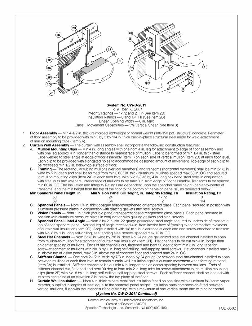
System No. CW-D-2011November 30, 2001
Integrity Ratings — 1-1/2 and 2 Hr (See Item 2B)Insulation Ratings — 0 and 1/4 Hr (See Item 2B)
Linear Opening Width — 8 in. MaxClass II Movement Capabilities — 5% Vertical Shear (See Item 3)
1. Floor Assembly — Min 4-1/2 in. thick reinforced lightweight or normal weight (100-150 pcf) structural concrete. Perimeter of fl oor assembly to be provided with min 3 by 3 by 1/4 in. thick cast-in-place structural steel angle for weld-attachment of mullion mounting clips (Item 2A).
2. Curtain Wall Assembly — The curtain wall assembly shall incorporate the following construction features:A. Mullion Mounting Clips — Min 4 in. long angles with one nom 4 in. leg for attachment to edge of fl oor assembly and
with one leg approx 4 in. longer than distance to nearest face of mullion. Clips to be formed of min 1/4 in. thick steel. Clips welded to steel angle at edge of fl oor assembly (Item 1) on each side of vertical mullion (Item 2B) at each fl oor level. Each clip to be provided with elongated holes to accommodate designed amount of movement. Top edge of each clip to be recessed min 1/2 in. below top surface of fl oor.
B. Framing — The rectangular tubing mullions (vertical members) and transoms (horizontal members) shall be min 2-1/2 in. wide by 5 in. deep and shall be formed from min 0.085 in. thick aluminum. Mullions spaced max 60 in. OC and secured to mullion mounting clips (Item 2A) at each fl oor level with two 3/8-16 by 4 in. long hex head steel bolts in conjunction with steel nuts and washers. Interior face of mullions to be max 8 in. from edge of fl oor assembly. Transoms to be spaced min 60 in. OC. The Insulation and Integrity Ratings are dependent upon the spandrel panel height (center-to-center of transoms) and the min height from the top of the fl oor to the bottom of the vision panel sill, as tabulated below:
Min Spandrel Panel Height, in. Min Vision Panel Sill Height, in. Integrity Rating, Hr Insulation Rating, Hr 60 24 1-1/2 0 69 34 2 1/4C. Spandrel Panels — Nom 1/4 in. thick opaque heat-strengthened or tempered glass. Each panel secured in position with
aluminum pressure plates in conjunction with glazing gaskets and steel screws.D. Vision Panels — Nom 1 in. thick (double pane) transparent heat-strengthened glass panels. Each panel secured in
position with aluminum pressure plates in conjunction with glazing gaskets and steel screws.E. Spandrel Panel Lintel Angle — Nom 2 by 2 in. No. 22 gauge galvanized steel angle secured to underside of transom at
top of each spandrel panel. Vertical leg of angle recessed 4 in. from interior face of framing to accommodate thickness of curtain wall insulation (Item 2G). Angle installed with 1/8 to 1 in. clearance at each end and screw-attached to transom with No. 8 by 1 in. long self-drilling, self-tapping steel screws spaced max 12 in. OC.
F. Steel Hat Channels — Nom 2-1/2 in. wide by 7/8 in. deep No. 24 gauge galvanized steel hat channel installed to span from mullion-to-mullion for attachment of curtain wall insulation (Item 2H). Hat channels to be cut min 4 in. longer than on center spacing of mullions. Ends of hat channels cut, fl attened and bent 90 deg to form min 2 in. long tabs for screw-attachment to mullions with No. 8 by 1 in. long self-drilling, self-tapping steel screws. Hat channels installed max 3 in. above top of vision panel, max 3 in. above top of concrete fl oor and spaced max 24 in. OC.
G. Stiffener Channel — One nom 2-1/2 in. wide by 7/8 in. deep by 24 gauge (or heavier) steel hat-channel installed to span between mullions at each fl oor level to restrain curtain wall insulation against outward movement when forming material (Item 3A) is installed. Stiffener channel to be cut min 4 in. longer than on center spacing between mullions. Ends of stiffener channel cut, fl attened and bent 90 deg to form min 2 in. long tabs for screw-attachment to the mullion mounting clips (Item 2E) with No. 8 by 1 in. long self-drilling, self-tapping steel screws. Each stiffener channel shall be located with its stem centerline at an elevation 2 in. below the top plane of the fl oor.
H. Curtain Wall Insulation* — Nom 4 in. thick mineral wool batt insulation faced on one side with aluminum foil/scrim vapor retarder, supplied in lengths at least equal to the spandrel panel height. Insulation batts compression-fi tted between vertical mullions, fl ush with the interior surface of framing, with a maximum of one vertical seam and with no horizontal
Reproduced courtesy of Underwriters Laboratories, Inc.Created or Revised: 12/03/01
Specifi ed Technologies, Inc., Somerville, NJ (800) 992-1180 FOD-3502
(System No. CW-D-2011 Continued)
seams. Insulation panels secured to the spandrel panel lintel angle and to each hat channel with min 4-1/2 in. long steel screws with min 1-1/2 in. diameter galv steel clinch shields spaced 3 in. from each vertical edge of batt and spaced max 24 in. OC between vertical edges of batt.
THERMAFIBER LLC — FIRESPAN SS InsulationJ. Framing Covers — Curtain Wall Insulation* — Min 8 in. wide strips cut from min 2 in. thick mineral wool batt insulation.
Framing covers to be centered over mullions and secured to the spandrel panel lintel angle and steel hat channels with min 6-1/2 in. long steel screws. Framing covers on mullions to abut the mineral wool batt safi ng material (Item 3A) above and below fl oor. Where more than one spandrel panel occurs between vertically separated vision panels, the horizontal transom between spandrel panels shall also be covered with an 8 in. wide framing cover in the same manner as on the vertical mullions.
THERMAFIBER LLC — FIRESPAN Insulation3. Safi ng System — Max separation between edge of fl oor assembly and face of framing members (at time of installation) is
8 in. The safi ng system is designed to accommodate vertical shear movement up to a max of 5 percent of its installed width. The safi ng system shall incorporate the following construction features:A. Forming Material* — Nom 4 pcf density mineral wool batt insulation. Batt sections cut to a min 4-1/2 in. width and stacked to
a thickness which is min 20 percent greater than the width of linear gap between the curtain wall insulation and the edge of the concrete fl oor slab. The forming material is compressed and inserted cut-edge-fi rst into linear gap such that its top surface is fl ush with the top surface of the fl oor assembly. A max of one tightly-butted seam is permitted between mullions. Additional pieces of forming material to be friction-fi t into spaces between mullion mounting clips at each mullion location.
THERMAFIBER LLC — SAFB. Fill, Void or Cavity Material* — Min 1/8 in. wet thickness (min 1/16 in. dry thickness) of fi ll material spray-applied over
top of forming material and lapping min 1/2 in. onto the top surface of the fl oor and onto the curtain wall insulation and framing covers.
SPECIFIED TECHNOLOGIES INC — SpecSeal AS200 Elastomeric Spray*Bearing the UL Classifi cation Marking
(System No. CW-D-2011 Continued)
FOD-3502
Reproduced courtesy of Underwriters Laboratories, Inc.Created or Revised: 12/03/01
Specifi ed Technologies, Inc., Somerville, NJ (800) 992-1180
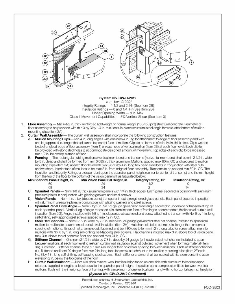
System No. CW-D-2012November 30, 2001
Integrity Ratings — 1-1/2 and 2 Hr (See Item 2B)Insulation Ratings — 0 and 1/4 Hr (See Item 2B)
Linear Opening Width — 8 in. MaxClass II Movement Capabilities — 5% Vertical Shear (See Item 3)
1. Floor Assembly — Min 4-1/2 in. thick reinforced lightweight or normal weight (100-150 pcf) structural concrete. Perimeter of fl oor assembly to be provided with min 3 by 3 by 1/4 in. thick cast-in-place structural steel angle for weld-attachment of mullion mounting clips (Item 2A).
2. Curtain Wall Assembly — The curtain wall assembly shall incorporate the following construction features:A. Mullion Mounting Clips— Min 4 in. long angles with one nom 4 in. leg for attachment to edge of fl oor assembly and with
one leg approx 4 in. longer than distance to nearest face of mullion. Clips to be formed of min 1/4 in. thick steel. Clips welded to steel angle at edge of fl oor assembly (Item 1) on each side of vertical mullion (Item 2B) at each fl oor level. Each clip to be provided with elongated holes to accommodate designed amount of movement. Top edge of each clip to be recessed min 1/2 in. below top surface of fl oor.
B. Framing — The rectangular tubing mullions (vertical members) and transoms (horizontal members) shall be min 2-1/2 in. wide by 5 in. deep and shall be formed from min 0.085 in. thick aluminum. Mullions spaced max 60 in. OC and secured to mullion mounting clips (Item 2A) at each fl oor level with two 3/8-16 by 4 in. long hex head steel bolts in conjunction with steel nuts and washers. Interior face of mullions to be max 8 in. from edge of fl oor assembly. Transoms to be spaced min 60 in. OC. The Insulation and Integrity Ratings are dependent upon the spandrel panel height (center-to-center of transoms) and the min height from the top of the fl oor to the bottom of the vision panel sill, as tabulated below:
Min Spandrel Panel Height, in. Min Vision Panel Sill Height, in. Integrity Rating, Hr Insulation Rating, Hr 60 24 1-1/2 0 69 34 2 1/4C. Spandrel Panels — Nom 1/8 in. thick aluminum panels with 1/4 in. thick edges. Each panel secured in position with aluminum
pressure plates in conjunction with glazing gaskets and steel screws.D. Vision Panels — Nom 1 in. thick (double pane) transparent heat-strengthened glass panels. Each panel secured in position
with aluminum pressure plates in conjunction with glazing gaskets and steel screws.E. Spandrel Panel Lintel Angle — Nom 2 by 2 in. No. 22 gauge galvanized steel angle secured to underside of transom at top of
each spandrel panel. Vertical leg of angle recessed 4 in. from interior face of framing to accommodate thickness of curtain wall insulation (Item 2G). Angle installed with 1/8 to 1 in. clearance at each end and screw-attached to transom with No. 8 by 1 in. long self-drilling, self-tapping steel screws spaced max 12 in. OC.
F. Steel Hat Channels — Nom 2-1/2 in. wide by 7/8 in. deep No. 24 gauge galvanized steel hat channel installed to span from mullion-to-mullion for attachment of curtain wall insulation (Item 2H). Hat channels to be cut min 4 in. longer than on center spacing of mullions. Ends of hat channels cut, fl attened and bent 90 deg to form min 2 in. long tabs for screw-attachment to mullions with No. 8 by 1 in. long self-drilling, self-tapping steel screws. Hat channels installed max 3 in. above top of vision panel, max 3 in. above top of concrete fl oor and spaced max 24 in. OC.
G. Stiffener Channel — One nom 2-1/2 in. wide by 7/8 in. deep by 24 gauge (or heavier) steel hat-channel installed to span between mullions at each fl oor level to restrain curtain wall insulation against outward movement when forming material (Item 3A) is installed. Stiffener channel to be cut min 4 in. longer than on center spacing between mullions. Ends of stiffener channel cut, fl attened and bent 90 deg to form min 2 in. long tabs for screw-attachment to the mullion mounting clips (Item 2E) with No. 8 by 1 in. long self-drilling, self-tapping steel screws. Each stiffener channel shall be located with its stem centerline at an elevation 2 in. below the top plane of the fl oor.
H. Curtain Wall Insulation* — Nom 4 in. thick mineral wool batt insulation faced on one side with aluminum foil/scrim vapor retarder, supplied in lengths at least equal to the spandrel panel height. Insulation batts compression-fi tted between vertical mullions, fl ush with the interior surface of framing, with a maximum of one vertical seam and with no horizontal seams. Insulation
Reproduced courtesy of Underwriters Laboratories, Inc.Created or Revised: 12/03/01
Specifi ed Technologies, Inc., Somerville, NJ (800) 992-1180 FOD-3503
(System No. CW-D-2012 Continued)
panels secured to the spandrel panel lintel angle and to each hat channel with min 4-1/2 in. long steel screws with min 1-1/2 in. diameter galv steel clinch shields spaced 3 in. from each vertical edge of batt and spaced max 24 in. OC between vertical edges of batt.
THERMAFIBER LLC — FIRESPAN SS InsulationJ. Framing Covers — Curtain Wall Insulation* — Min 8 in. wide strips cut from min 2 in. thick mineral wool batt insulation.
Framing covers to be centered over mullions and secured to the spandrel panel lintel angle and steel hat channels with min 6-1/2 in. long steel screws. Framing covers on mullions to abut the mineral wool batt safi ng material (Item 3A) above and below fl oor. Where more than one spandrel panel occurs between vertically separated vision panels, the horizontal transom between spandrel panels shall also be covered with an 8 in. wide framing cover in the same manner as on the vertical mullions.
THERMAFIBER LLC — FIRESPAN Insulation3. Safi ng System — Max separation between edge of fl oor assembly and face of framing members (at time of installation) is 8
in. The safi ng system is designed to accommodate vertical shear movement up to a max of 5 percent of its installed width. The safi ng system shall incorporate the following construction features:A. Forming Material* — Nom 4 pcf density mineral wool batt insulation. Batt sections cut to a min 4-1/2 in. width and stacked to
a thickness which is min 20 percent greater than the width of linear gap between the curtain wall insulation and the edge of the concrete fl oor slab. The forming material is compressed and inserted cut-edge-fi rst into linear gap such that its top surface is fl ush with the top surface of the fl oor assembly. A max of one tightly-butted seam is permitted between mullions. Additional pieces of forming material to be friction-fi t into spaces between mullion mounting clips at each mullion location.
THERMAFIBER LLC — SAFB. Fill, Void or Cavity Material* — Min 1/8 in. wet thickness (min 1/16 in. dry thickness) of fi ll material spray-applied over
top of forming material and lapping min 1/2 in. onto the top surface of the fl oor and onto the curtain wall insulation and framing covers.
SPECIFIED TECHNOLOGIES INC — SpecSeal AS200 Elastomeric Spray*Bearing the UL Classifi cation Marking
(System No. CW-D-2012 Continued)
FOD-3503
Reproduced courtesy of Underwriters Laboratories, Inc.Created or Revised: 12/03/01
Specifi ed Technologies, Inc., Somerville, NJ (800) 992-1180
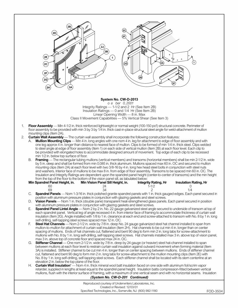
System No. CW-D-2013November 30, 2001
Integrity Ratings — 1-1/2 and 2 Hr (See Item 2B)Insulation Ratings — 0 and 1/4 Hr (See Item 2B)
Linear Opening Width — 8 in. MaxClass II Movement Capabilities — 5% Vertical Shear (See Item 3)
1. Floor Assembly — Min 4-1/2 in. thick reinforced lightweight or normal weight (100-150 pcf) structural concrete. Perimeter of fl oor assembly to be provided with min 3 by 3 by 1/4 in. thick cast-in-place structural steel angle for weld-attachment of mullion mounting clips (Item 2A).
2. Curtain Wall Assembly — The curtain wall assembly shall incorporate the following construction features:A. Mullion Mounting Clips — Min 4 in. long angles with one nom 4 in. leg for attachment to edge of fl oor assembly and with
one leg approx 4 in. longer than distance to nearest face of mullion. Clips to be formed of min 1/4 in. thick steel. Clips welded to steel angle at edge of fl oor assembly (Item 1) on each side of vertical mullion (Item 2B) at each fl oor level. Each clip to be provided with elongated holes to accommodate designed amount of movement. Top edge of each clip to be recessed min 1/2 in. below top surface of fl oor.
B. Framing — The rectangular tubing mullions (vertical members) and transoms (horizontal members) shall be min 2-1/2 in. wide by 5 in. deep and shall be formed from min 0.085 in. thick aluminum. Mullions spaced max 60 in. OC and secured to mullion mounting clips (Item 2A) at each fl oor level with two 3/8-16 by 4 in. long hex head steel bolts in conjunction with steel nuts and washers. Interior face of mullions to be max 8 in. from edge of fl oor assembly. Transoms to be spaced min 60 in. OC. The Insulation and Integrity Ratings are dependent upon the spandrel panel height (center-to-center of transoms) and the min height from the top of the fl oor to the bottom of the vision panel sill, as tabulated below:
Min Spandrel Panel Height, in. Min Vision Panel Sill Height, in. Integrity Rating, Hr Insulation Rating, Hr 60 24 1-1/2 0 69 34 2 1/4C. Spandrel Panels — Nom 1-3/16 in. thick polished granite spandrel panels with 1 in. thick gauged edges. Each panel secured in
position with aluminum pressure plates in conjunction with glazing gaskets and steel screws.D. Vision Panels — Nom 1 in. thick (double pane) transparent heat-strengthened glass panels. Each panel secured in position
with aluminum pressure plates in conjunction with glazing gaskets and steel screws.E. Spandrel Panel Lintel Angle — Nom 2 by 2 in. No. 22 gauge galvanized steel angle secured to underside of transom at top of
each spandrel panel. Vertical leg of angle recessed 4 in. from interior face of framing to accommodate thickness of curtain wall insulation (Item 2G). Angle installed with 1/8 to 1 in. clearance at each end and screw-attached to transom with No. 8 by 1 in. long self-drilling, self-tapping steel screws spaced max 12 in. OC.
F. Steel Hat Channels — Nom 2-1/2 in. wide by 7/8 in. deep No. 24 gauge galvanized steel hat channel installed to span from mullion-to-mullion for attachment of curtain wall insulation (Item 2H). Hat channels to be cut min 4 in. longer than on center spacing of mullions. Ends of hat channels cut, fl attened and bent 90 deg to form min 2 in. long tabs for screw-attachment to mullions with No. 8 by 1 in. long self-drilling, self-tapping steel screws. Hat channels installed max 3 in. above top of vision panel, max 3 in. above top of concrete fl oor and spaced max 24 in. OC.
G. Stiffener Channel — One nom 2-1/2 in. wide by 7/8 in. deep by 24 gauge (or heavier) steel hat-channel installed to span between mullions at each fl oor level to restrain curtain wall insulation against outward movement when forming material (Item 3A) is installed. Stiffener channel to be cut min 4 in. longer than on center spacing between mullions. Ends of stiffener channel cut, fl attened and bent 90 deg to form min 2 in. long tabs for screw-attachment to the mullion mounting clips (Item 2E) with No. 8 by 1 in. long self-drilling, self-tapping steel screws. Each stiffener channel shall be located with its stem centerline at an elevation 2 in. below the top plane of the fl oor.
H. Curtain Wall Insulation* — Nom 4 in. thick mineral wool batt insulation faced on one side with aluminum foil/scrim vapor retarder, supplied in lengths at least equal to the spandrel panel height. Insulation batts compression-fi tted between vertical mullions, fl ush with the interior surface of framing, with a maximum of one vertical seam and with no horizontal seams. Insulation
Reproduced courtesy of Underwriters Laboratories, Inc.Created or Revised: 12/03/01
Specifi ed Technologies, Inc., Somerville, NJ (800) 992-1180 FOD-3504
(System No. CW-D-2013 Continued)

panels secured to the spandrel panel lintel angle and to each hat channel with min 4-1/2 in. long steel screws with min 1-1/2 in. diameter galv steel clinch shields spaced 3 in. from each vertical edge of batt and spaced max 24 in. OC between vertical edges of batt.
THERMAFIBER LLC — FIRESPAN SS InsulationJ. Framing Covers — Curtain Wall Insulation* — Min 8 in. wide strips cut from min 2 in. thick mineral wool batt insulation.
Framing covers to be centered over mullions and secured to the spandrel panel lintel angle and steel hat channels with min 6-1/2 in. long steel screws. Framing covers on mullions to abut the mineral wool batt safi ng material (Item 3A) above and below fl oor. Where more than one spandrel panel occurs between vertically separated vision panels, the horizontal transom between spandrel panels shall also be covered with an 8 in. wide framing cover in the same manner as on the vertical mullions.
THERMAFIBER LLC — FIRESPAN Insulation3. Safi ng System — Max separation between edge of fl oor assembly and face of framing members (at time of installation) is 8
in. The safi ng system is designed to accommodate vertical shear movement up to a max of 5 percent of its installed width. The safi ng system shall incorporate the following construction features:A. Forming Material* — Nom 4 pcf density mineral wool batt insulation. Batt sections cut to a min 4-1/2 in. width and stacked to
a thickness which is min 20 percent greater than the width of linear gap between the curtain wall insulation and the edge of the concrete fl oor slab. The forming material is compressed and inserted cut-edge-fi rst into linear gap such that its top surface is fl ush with the top surface of the fl oor assembly. A max of one tightly-butted seam is permitted between mullions. Additional pieces of forming material to be friction-fi t into spaces between mullion mounting clips at each mullion location.
THERMAFIBER LLC — SAFB. Fill, Void or Cavity Material* — Min 1/8 in. wet thickness (min 1/16 in. dry thickness) of fi ll material spray-applied over
top of forming material and lapping min 1/2 in. onto the top surface of the fl oor and onto the curtain wall insulation and framing covers.
SPECIFIED TECHNOLOGIES INC — SpecSeal AS200 Elastomeric Spray*Bearing the UL Classifi cation Marking
(System No. CW-D-2013 Continued)
FOD-3504
Reproduced courtesy of Underwriters Laboratories, Inc.Created or Revised: 12/03/01
Specifi ed Technologies, Inc., Somerville, NJ (800) 992-1180
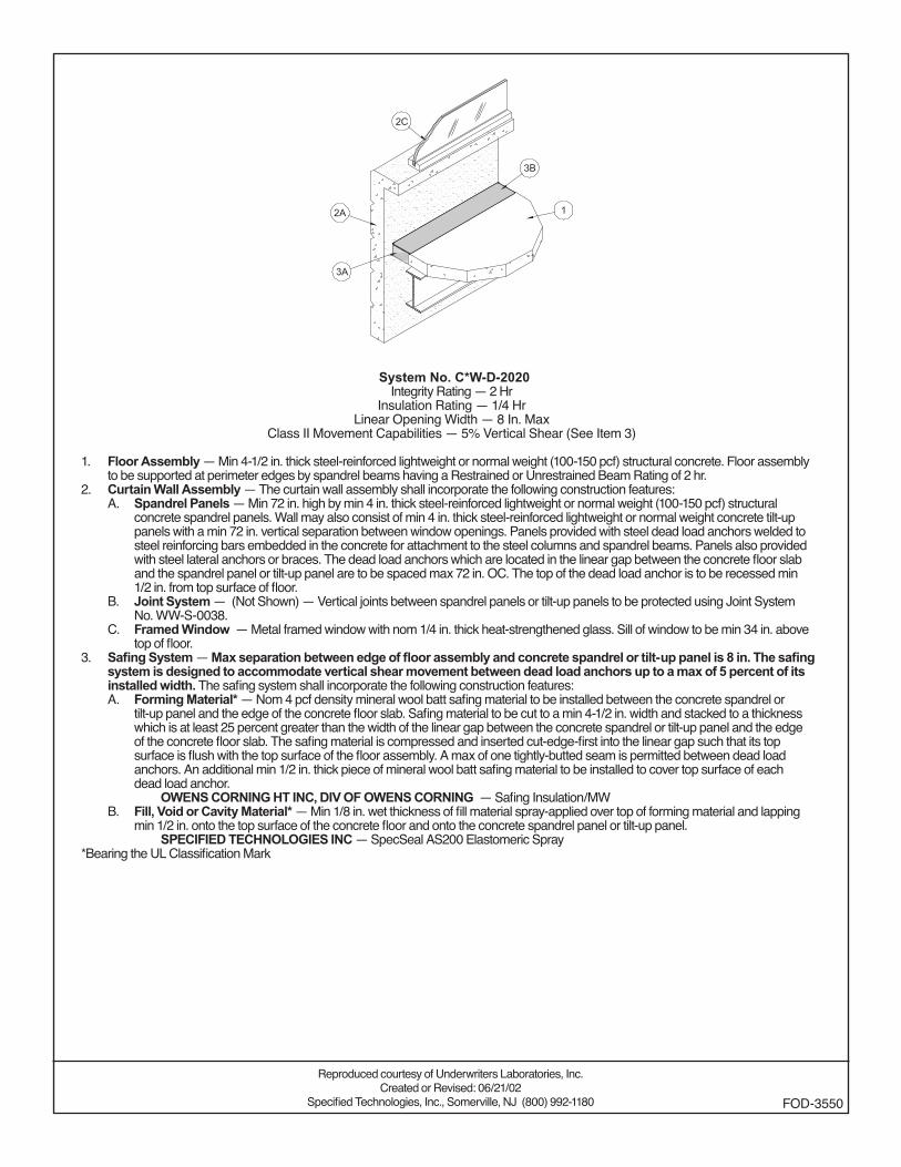
System No. CW-D-2020Integrity Rating — 2 Hr
Insulation Rating — 1/4 HrLinear Opening Width — 8 In. Max
Class II Movement Capabilities — 5% Vertical Shear (See Item 3)
1. Floor Assembly — Min 4-1/2 in. thick steel-reinforced lightweight or normal weight (100-150 pcf) structural concrete. Floor assembly to be supported at perimeter edges by spandrel beams having a Restrained or Unrestrained Beam Rating of 2 hr.
2. Curtain Wall Assembly — The curtain wall assembly shall incorporate the following construction features:A. Spandrel Panels — Min 72 in. high by min 4 in. thick steel-reinforced lightweight or normal weight (100-150 pcf) structural
concrete spandrel panels. Wall may also consist of min 4 in. thick steel-reinforced lightweight or normal weight concrete tilt-up panels with a min 72 in. vertical separation between window openings. Panels provided with steel dead load anchors welded to steel reinforcing bars embedded in the concrete for attachment to the steel columns and spandrel beams. Panels also provided with steel lateral anchors or braces. The dead load anchors which are located in the linear gap between the concrete floor slab and the spandrel panel or tilt-up panel are to be spaced max 72 in. OC. The top of the dead load anchor is to be recessed min 1/2 in. from top surface of floor.
B. Joint System — (Not Shown) — Vertical joints between spandrel panels or tilt-up panels to be protected using Joint System No. WW-S-0038.
C. Framed Window — Metal framed window with nom 1/4 in. thick heat-strengthened glass. Sill of window to be min 34 in. above top of floor.
3. Safing System — Max separation between edge of floor assembly and concrete spandrel or tilt-up panel is 8 in. The safing system is designed to accommodate vertical shear movement between dead load anchors up to a max of 5 percent of its installed width. The safing system shall incorporate the following construction features:A. Forming Material* — Nom 4 pcf density mineral wool batt safing material to be installed between the concrete spandrel or
tilt-up panel and the edge of the concrete floor slab. Safing material to be cut to a min 4-1/2 in. width and stacked to a thickness which is at least 25 percent greater than the width of the linear gap between the concrete spandrel or tilt-up panel and the edge of the concrete floor slab. The safing material is compressed and inserted cut-edge-first into the linear gap such that its top surface is flush with the top surface of the floor assembly. A max of one tightly-butted seam is permitted between dead load anchors. An additional min 1/2 in. thick piece of mineral wool batt safing material to be installed to cover top surface of each dead load anchor.
OWENS CORNING HT INC, DIV OF OWENS CORNING — Safing Insulation/MWB. Fill, Void or Cavity Material* — Min 1/8 in. wet thickness of fill material spray-applied over top of forming material and lapping
min 1/2 in. onto the top surface of the concrete floor and onto the concrete spandrel panel or tilt-up panel. SPECIFIED TECHNOLOGIES INC — SpecSeal AS200 Elastomeric Spray
*Bearing the UL Classification Mark
Reproduced courtesy of Underwriters Laboratories, Inc.Created or Revised: 06/21/02
Specified Technologies, Inc., Somerville, NJ (800) 992-1180 FOD-3550
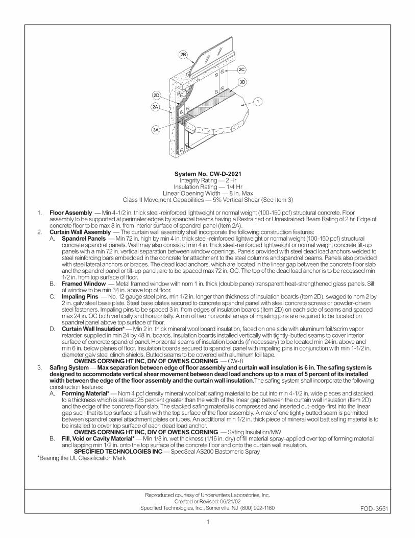
1
System No. CW-D-2021Integrity Rating — 2 Hr
Insulation Rating — 1/4 HrLinear Opening Width — 8 in. Max
Class II Movement Capabilities — 5% Vertical Shear (See Item 3)
1. Floor Assembly — Min 4-1/2 in. thick steel-reinforced lightweight or normal weight (100-150 pcf) structural concrete. Floor assembly to be supported at perimeter edges by spandrel beams having a Restrained or Unrestrained Beam Rating of 2 hr. Edge of concrete floor to be max 8 in. from interior surface of spandrel panel (Item 2A).
2. Curtain Wall Assembly — The curtain wall assembly shall incorporate the following construction features:A. Spandrel Panels — Min 72 in. high by min 4 in. thick steel-reinforced lightweight or normal weight (100-150 pcf) structural
concrete spandrel panels. Wall may also consist of min 4 in. thick steel-reinforced lightweight or normal weight concrete tilt-up panels with a min 72 in. vertical separation between window openings. Panels provided with steel dead load anchors welded to steel reinforcing bars embedded in the concrete for attachment to the steel columns and spandrel beams. Panels also provided with steel lateral anchors or braces. The dead load anchors, which are located in the linear gap between the concrete floor slab and the spandrel panel or tilt-up panel, are to be spaced max 72 in. OC. The top of the dead load anchor is to be recessed min 1/2 in. from top surface of floor.
B. Framed Window — Metal framed window with nom 1 in. thick (double pane) transparent heat-strengthened glass panels. Sill of window to be min 34 in. above top of floor.
C. Impaling Pins — No. 12 gauge steel pins, min 1/2 in. longer than thickness of insulation boards (Item 2D), swaged to nom 2 by 2 in. galv steel base plate. Steel base plates secured to concrete spandrel panel with steel concrete screws or powder-driven steel fasteners. Impaling pins to be spaced 3 in. from edges of insulation boards (Item 2D) on each side of seams and spaced max 24 in. OC both vertically and horizontally. A min of two horizontal arrays of impaling pins are required to be located on spandrel panel above top surface of floor.
D. Curtain Wall Insulation* — Min 2 in. thick mineral wool board insulation, faced on one side with aluminum foil/scrim vapor retarder, supplied in min 24 by 48 in. boards. Insulation boards installed vertically with tightly-butted seams to cover interior surface of concrete spandrel panel. Horizontal seams of insulation boards (if necessary) to be located min 24 in. above and min 6 in. below planes of floor. Insulation boards secured to spandrel panel with impaling pins in conjunction with min 1-1/2 in. diameter galv steel clinch shields. Butted seams to be covered with aluminum foil tape.
OWENS CORNING HT INC, DIV OF OWENS CORNING — CW-83. Safing System — Max separation between edge of floor assembly and curtain wall insulation is 6 in. The safing system is
designed to accommodate vertical shear movement between dead load anchors up to a max of 5 percent of its installed width between the edge of the floor assembly and the curtain wall insulation. The safing system shall incorporate the following construction features:A. Forming Material* — Nom 4 pcf density mineral wool batt safing material to be cut into min 4-1/2 in. wide pieces and stacked
to a thickness which is at least 25 percent greater than the width of the linear gap between the curtain wall insulation (Item 2D) and the edge of the concrete floor slab. The stacked safing material is compressed and inserted cut-edge-first into the linear gap such that its top surface is flush with the top surface of the floor assembly. A max of one tightly butted seam is permitted between spandrel panel attachment plates or tubes. An additional min 1/2 in. thick piece of mineral wool batt safing material is to be installed to cover top surface of each dead load anchor.
OWENS CORNING HT INC, DIV OF OWENS CORNING — Safing Insulation/MWB. Fill, Void or Cavity Material* — Min 1/8 in. wet thickness (1/16 in. dry) of fill material spray-applied over top of forming material
and lapping min 1/2 in. onto the top surface of the concrete floor and onto the curtain wall insulation. SPECIFIED TECHNOLOGIES INC — SpecSeal AS200 Elastomeric Spray
*Bearing the UL Classification Mark
Reproduced courtesy of Underwriters Laboratories, Inc.Created or Revised: 06/21/02
Specified Technologies, Inc., Somerville, NJ (800) 992-1180 FOD-3551
3B
3A
2B
2A1
2C
2D
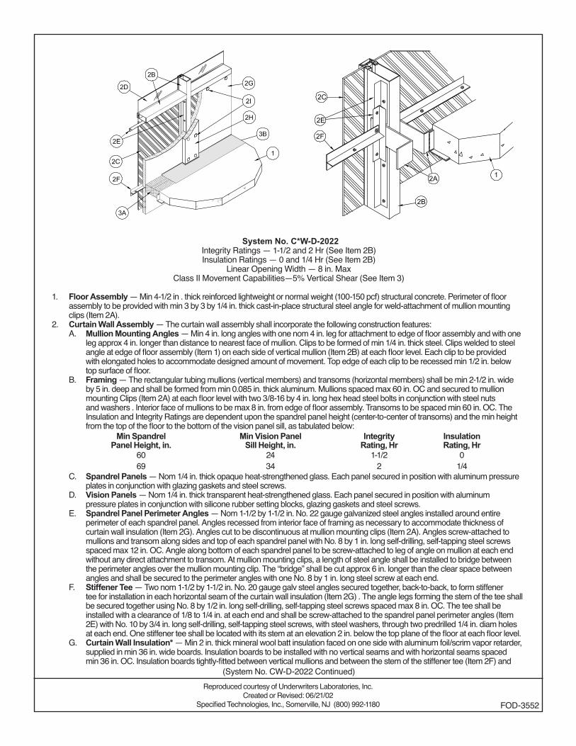
System No. CW-D-2022Integrity Ratings — 1-1/2 and 2 Hr (See Item 2B)Insulation Ratings — 0 and 1/4 Hr (See Item 2B)
Linear Opening Width — 8 in. MaxClass II Movement Capabilities—5% Vertical Shear (See Item 3)
1. Floor Assembly — Min 4-1/2 in . thick reinforced lightweight or normal weight (100-150 pcf) structural concrete. Perimeter of floor assembly to be provided with min 3 by 3 by 1/4 in. thick cast-in-place structural steel angle for weld-attachment of mullion mounting clips (Item 2A).
2. Curtain Wall Assembly — The curtain wall assembly shall incorporate the following construction features:A. Mullion Mounting Angles — Min 4 in. long angles with one nom 4 in. leg for attachment to edge of floor assembly and with one
leg approx 4 in. longer than distance to nearest face of mullion. Clips to be formed of min 1/4 in. thick steel. Clips welded to steel angle at edge of floor assembly (Item 1) on each side of vertical mullion (Item 2B) at each floor level. Each clip to be provided with elongated holes to accommodate designed amount of movement. Top edge of each clip to be recessed min 1/2 in. below top surface of floor.
B. Framing — The rectangular tubing mullions (vertical members) and transoms (horizontal members) shall be min 2-1/2 in. wide by 5 in. deep and shall be formed from min 0.085 in. thick aluminum. Mullions spaced max 60 in. OC and secured to mullion mounting Clips (Item 2A) at each floor level with two 3/8-16 by 4 in. long hex head steel bolts in conjunction with steel nuts and washers . Interior face of mullions to be max 8 in. from edge of floor assembly. Transoms to be spaced min 60 in. OC. The Insulation and Integrity Ratings are dependent upon the spandrel panel height (center-to-center of transoms) and the min height from the top of the floor to the bottom of the vision panel sill, as tabulated below:
Min Spandrel Panel Height, in.
Min Vision PanelSill Height, in.
IntegrityRating, Hr
InsulationRating, Hr
60 24 1-1/2 069 34 2 1/4
C. Spandrel Panels — Nom 1/4 in. thick opaque heat-strengthened glass. Each panel secured in position with aluminum pressure plates in conjunction with glazing gaskets and steel screws.
D. Vision Panels — Nom 1/4 in. thick transparent heat-strengthened glass. Each panel secured in position with aluminum pressure plates in conjunction with silicone rubber setting blocks, glazing gaskets and steel screws.
E. Spandrel Panel Perimeter Angles — Nom 1-1/2 by 1-1/2 in. No. 22 gauge galvanized steel angles installed around entire perimeter of each spandrel panel. Angles recessed from interior face of framing as necessary to accommodate thickness of curtain wall insulation (Item 2G). Angles cut to be discontinuous at mullion mounting clips (Item 2A). Angles screw-attached to mullions and transom along sides and top of each spandrel panel with No. 8 by 1 in. long self-drilling, self-tapping steel screws spaced max 12 in. OC. Angle along bottom of each spandrel panel to be screw-attached to leg of angle on mullion at each end without any direct attachment to transom. At mullion mounting clips, a length of steel angle shall be installed to bridge between the perimeter angles over the mullion mounting clip. The “bridge” shall be cut approx 6 in. longer than the clear space between angles and shall be secured to the perimeter angles with one No. 8 by 1 in. long steel screw at each end.
F. Stiffener Tee — Two nom 1-1/2 by 1-1/2 in. No. 20 gauge galv steel angles secured together, back-to-back, to form stiffener tee for installation in each horizontal seam of the curtain wall insulation (Item 2G) . The angle legs forming the stem of the tee shall be secured together using No. 8 by 1/2 in. long self-drilling, self-tapping steel screws spaced max 8 in. OC. The tee shall be installed with a clearance of 1/8 to 1/4 in. at each end and shall be screw-attached to the spandrel panel perimeter angles (Item 2E) with No. 10 by 3/4 in. long self-drilling, self-tapping steel screws, with steel washers, through two predrilled 1/4 in. diam holes at each end. One stiffener tee shall be located with its stem at an elevation 2 in. below the top plane of the floor at each floor level.
G. Curtain Wall Insulation* — Min 2 in. thick mineral wool batt insulation faced on one side with aluminum foil/scrim vapor retarder, supplied in min 36 in. wide boards. Insulation boards to be installed with no vertical seams and with horizontal seams spaced min 36 in. OC. Insulation boards tightly-fitted between vertical mullions and between the stem of the stiffener tee (Item 2F) and
Reproduced courtesy of Underwriters Laboratories, Inc.Created or Revised: 06/21/02
Specified Technologies, Inc., Somerville, NJ (800) 992-1180 FOD-3552
(System No. CW-D-2022 Continued)
the transom, flush with the interior surface of framing. Insulation boards secured to spandrel panel perimeter angles and to each stiffener tee with cup head weld pins (Item 2I) spaced max 12 in. OC. The horizontal seam between insulation boards shall be located 2 in. below the top plane of the floor at each floor level.
OWENS CORNING HT INC, DIV OF OWENS CORNING — CW-8H. Framing Covers — Curtain Wall Insulation* — Min 1 in. thick mineral wool batt insulation faced on one side with aluminum
foil/scrim vapor retarder, supplied in min 24 by 48 in. boards. Nom 8 in. wide strips to be centered over mullions and secured to the spandrel panel perimeter angles with cup head weld pins (Item 2I) spaced max 12 in. OC. Where more than one spandrel panel occurs between vertically separated vision panels, the horizontal transom between spandrel panels shall also be covered with an 8 in. wide framing cover in the same manner as on the vertical mullions. Framing covers on mullions to abut the mineral wool batt safing material (Item 3A) above and below floor.
OWENS CORNING HT INC, DIV OF OWENS CORNING — CW-8I. Weld Pin — No. 12 gauge galv steel weld pin with nom 1-3/16 in. diam galv steel cup head. Cup head weld pins provided in
two lengths. One length to be equal to thickness of curtain wall insulation (Item 2G) and second length to be equal to thickness of curtain wall insulation plus thickness of framing cover (Item 2H). Cup head weld pins inserted through curtain wall insulation and mullion covers and welded to spandrel panel perimeter angles max 12 in. OC.
J. Steel Screw And Clinch Shield — (Not Shown) — As an alternate to the weld pins (Item 2I), self-drilling, self-tapping steel screws with min 1-1/2 in. diam galv steel clinch shields may be used to secure the curtain wall insulation and framing covers. Steel screws provided in two lengths. One length to be 1/2 in. greater than thickness of curtain wall insulation (Item 2G) and second length to be 1/2 in. greater than thickness of curtain wall insulation plus thickness of framing cover (Item 2H). Screws secured to spandrel panel perimeter angles, through curtain wall insulation and mullion covers, and spaced max 12 in. OC.
3. Safing System — Max separation between edge of floor assembly and face of framing members (at time of installation) is 8 in. The safing system is designed to accommodate vertical shear movement up to a max of 5 percent of its installed width. The safing system shall incorporate the following construction features:A. Forming Material* — Nom 4 pcf density mineral wool batt insulation. Batt sections cut to a min 4-1/2 in. width and stacked to
a thickness which is min 20 percent greater than the width of linear gap between the curtain wall insulation and the edge of the concrete floor slab. The forming material is compressed and inserted cut-edge-first into linear gap such that its top surface is flush with the top surface of the floor assembly. A max of one tightly-butted seam is permitted between mullions. Additional pieces of forming material to be friction-fit into spaces between mullion mounting clips at each mullion location.
OWENS CORNING HT INC, DIV OF OWENS CORNING — Safing Insulation/MWB. Fill, Void or Cavity Material* — Min 1/8 in. wet thickness (min 1/16 in. dry thickness) of fill material spray-applied over top of
forming material and lapping min 1/2 in. onto the top surface of the floor and onto the curtain wall insulation and framing covers. SPECIFIED TECHNOLOGIES INC — SpecSeal AS200 Elastomeric Spray
*Bearing the UL Classification Mark
(System No. CW-D-2022 Continued)
Reproduced courtesy of Underwriters Laboratories, Inc.Created or Revised: 06/21/02
Specified Technologies, Inc., Somerville, NJ (800) 992-1180 FOD-3552
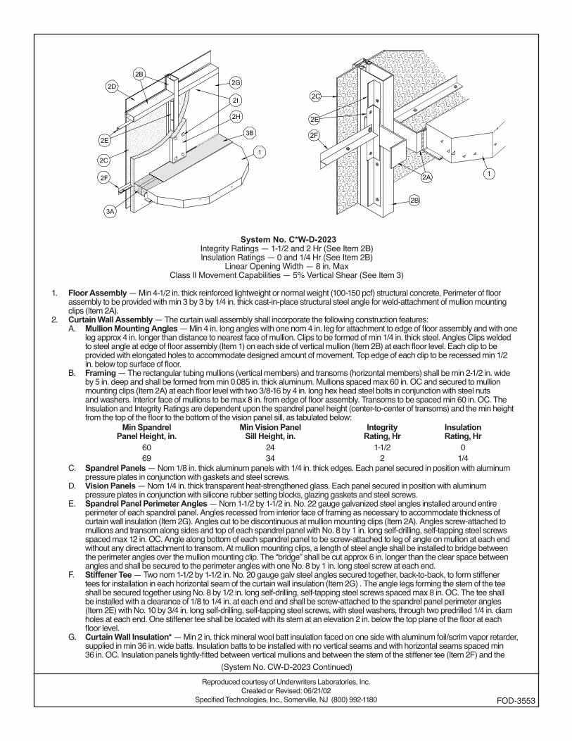
System No. CW-D-2023Integrity Ratings — 1-1/2 and 2 Hr (See Item 2B)Insulation Ratings — 0 and 1/4 Hr (See Item 2B)
Linear Opening Width — 8 in. MaxClass II Movement Capabilities — 5% Vertical Shear (See Item 3)
1. Floor Assembly — Min 4-1/2 in. thick reinforced lightweight or normal weight (100-150 pcf) structural concrete. Perimeter of floor assembly to be provided with min 3 by 3 by 1/4 in. thick cast-in-place structural steel angle for weld-attachment of mullion mounting clips (Item 2A).
2. Curtain Wall Assembly — The curtain wall assembly shall incorporate the following construction features:A. Mullion Mounting Angles — Min 4 in. long angles with one nom 4 in. leg for attachment to edge of floor assembly and with one
leg approx 4 in. longer than distance to nearest face of mullion. Clips to be formed of min 1/4 in. thick steel. Angles Clips welded to steel angle at edge of floor assembly (Item 1) on each side of vertical mullion (Item 2B) at each floor level. Each clip to be provided with elongated holes to accommodate designed amount of movement. Top edge of each clip to be recessed min 1/2 in. below top surface of floor.
B. Framing — The rectangular tubing mullions (vertical members) and transoms (horizontal members) shall be min 2-1/2 in. wide by 5 in. deep and shall be formed from min 0.085 in. thick aluminum. Mullions spaced max 60 in. OC and secured to mullion mounting clips (Item 2A) at each floor level with two 3/8-16 by 4 in. long hex head steel bolts in conjunction with steel nuts and washers. Interior face of mullions to be max 8 in. from edge of floor assembly. Transoms to be spaced min 60 in. OC. The Insulation and Integrity Ratings are dependent upon the spandrel panel height (center-to-center of transoms) and the min height from the top of the floor to the bottom of the vision panel sill, as tabulated below:
Min SpandrelPanel Height, in.
Min Vision PanelSill Height, in.
IntegrityRating, Hr
InsulationRating, Hr
60 24 1-1/2 069 34 2 1/4
C. Spandrel Panels — Nom 1/8 in. thick aluminum panels with 1/4 in. thick edges. Each panel secured in position with aluminum pressure plates in conjunction with gaskets and steel screws.
D. Vision Panels — Nom 1/4 in. thick transparent heat-strengthened glass. Each panel secured in position with aluminum pressure plates in conjunction with silicone rubber setting blocks, glazing gaskets and steel screws.
E. Spandrel Panel Perimeter Angles — Nom 1-1/2 by 1-1/2 in. No. 22 gauge galvanized steel angles installed around entire perimeter of each spandrel panel. Angles recessed from interior face of framing as necessary to accommodate thickness of curtain wall insulation (Item 2G). Angles cut to be discontinuous at mullion mounting clips (Item 2A). Angles screw-attached to mullions and transom along sides and top of each spandrel panel with No. 8 by 1 in. long self-drilling, self-tapping steel screws spaced max 12 in. OC. Angle along bottom of each spandrel panel to be screw-attached to leg of angle on mullion at each end without any direct attachment to transom. At mullion mounting clips, a length of steel angle shall be installed to bridge between the perimeter angles over the mullion mounting clip. The “bridge” shall be cut approx 6 in. longer than the clear space between angles and shall be secured to the perimeter angles with one No. 8 by 1 in. long steel screw at each end.
F. Stiffener Tee — Two nom 1-1/2 by 1-1/2 in. No. 20 gauge galv steel angles secured together, back-to-back, to form stiffener tees for installation in each horizontal seam of the curtain wall insulation (Item 2G) . The angle legs forming the stem of the tee shall be secured together using No. 8 by 1/2 in. long self-drilling, self-tapping steel screws spaced max 8 in. OC. The tee shall be installed with a clearance of 1/8 to 1/4 in. at each end and shall be screw-attached to the spandrel panel perimeter angles (Item 2E) with No. 10 by 3/4 in. long self-drilling, self-tapping steel screws, with steel washers, through two predrilled 1/4 in. diam holes at each end. One stiffener tee shall be located with its stem at an elevation 2 in. below the top plane of the floor at each floor level.
G. Curtain Wall Insulation* — Min 2 in. thick mineral wool batt insulation faced on one side with aluminum foil/scrim vapor retarder, supplied in min 36 in. wide batts. Insulation batts to be installed with no vertical seams and with horizontal seams spaced min 36 in. OC. Insulation panels tightly-fitted between vertical mullions and between the stem of the stiffener tee (Item 2F) and the
Reproduced courtesy of Underwriters Laboratories, Inc.Created or Revised: 06/21/02
Specified Technologies, Inc., Somerville, NJ (800) 992-1180 FOD-3553
(System No. CW-D-2023 Continued)
transom, flush with the interior surface of framing. Insulation panels secured to spandrel panel perimeter angles and to each stiffener tee with cup head weld pins (Item 2I) spaced max 12 in OC. The horizontal seam between insulation panels shall be located 2 in. below the top plane of the floor at each floor level.
OWENS CORNING HT INC, DIV OF OWENS CORNING — CW-8H. Framing Covers — Curtain Wall Insulation* Min 1 in. thick mineral wool batt insulation faced on one side with aluminum foil/
scrim vapor retarder, supplied in min 24 by 48 in. boards. Nom 8 in. wide strips to be centered over mullions and secured to the spandrel panel perimeter angles with cup head weld pins (Item 2I) spaced max 12 in. OC. Where more than one spandrel panel occurs between vertically separated vision panels, the horizontal transom between spandrel panels shall also be covered with an 8 in. wide framing cover in the same manner as on the vertical mullions. Framing covers on mullions to abut the mineral wool batt safing material (Item 3A) above and below floor.
OWENS CORNING HT INC, DIV OF OWENS CORNING — CW-8I. Weld Pin — No. 12 gauge galv steel weld pin with nom 1-3/16 in. diam galv steel cup head. Cup head weld pins provided in
two lengths. One length to be equal to thickness of curtain wall insulation (Item 2G) and second length to be equal to thickness of curtain wall insulation plus thickness of framing cover (Item 2H). Cup head weld pins inserted through curtain wall insulation and mullion covers and welded to spandrel panel perimeter angles max 12 in. OC.
J. Steel Screw And Clinch Shield — (Not Shown) — As an alternate to the weld pins (Item 2I), self-drilling, self-tapping steel screws with min 1-1/2 in. diam galv steel clinch shields may be used to secure the curtain wall insulation and framing covers. Steel screws provided in two lengths. One length to be 1/2 in. greater than thickness of curtain wall insulation (Item 2G) and second length to be 1/2 in. greater than thickness of curtain wall insulation plus thickness of framing cover (Item 2H). Screws secured to spandrel panel perimeter angles, through curtain wall insulation and mullion covers, and spaced max 12 in. OC.
3. Safing System — Max separation between edge of floor assembly and face of framing members (at time of installation) is 8 in. The safing system is designed to accommodate vertical shear movement up to a max of 5 percent of its installed width. The safing system shall incorporate the following construction features:A. Forming Material* — Nom 4 pcf density mineral wool batt insulation. Batt sections cut to a min 4-1/2 in. width and stacked to
a thickness which is min 20 percent greater than the width of linear gap between the curtain wall insulation and the edge of the concrete floor slab. The forming material is compressed and inserted cut-edge-first into linear gap such that its top surface is flush with the top surface of the floor assembly. A max of one tightly-butted seam is permitted between mullions. Additional pieces of forming material to be friction-fit into spaces between mullion mounting clips at each mullion location.
OWENS CORNING HT INC, DIV OF OWENS CORNING — Safing Insulation/MWB. Fill, Void or Cavity Material* — Min 1/8 in. wet thickness (min 1/16 in. dry thickness) of fill material spray- applied over top of
forming material and lapping min 1/2 in. onto the top surface of the floor and onto the curtain wall insulation and framing covers. SPECIFIED TECHNOLOGIES INC — SpecSeal AS200 Elastomeric Spray
*Bearing the UL Classification Mark
(System No. CW-D-2023 Continued)
Reproduced courtesy of Underwriters Laboratories, Inc.Created or Revised: 06/21/02
Specified Technologies, Inc., Somerville, NJ (800) 992-1180 FOD-3553
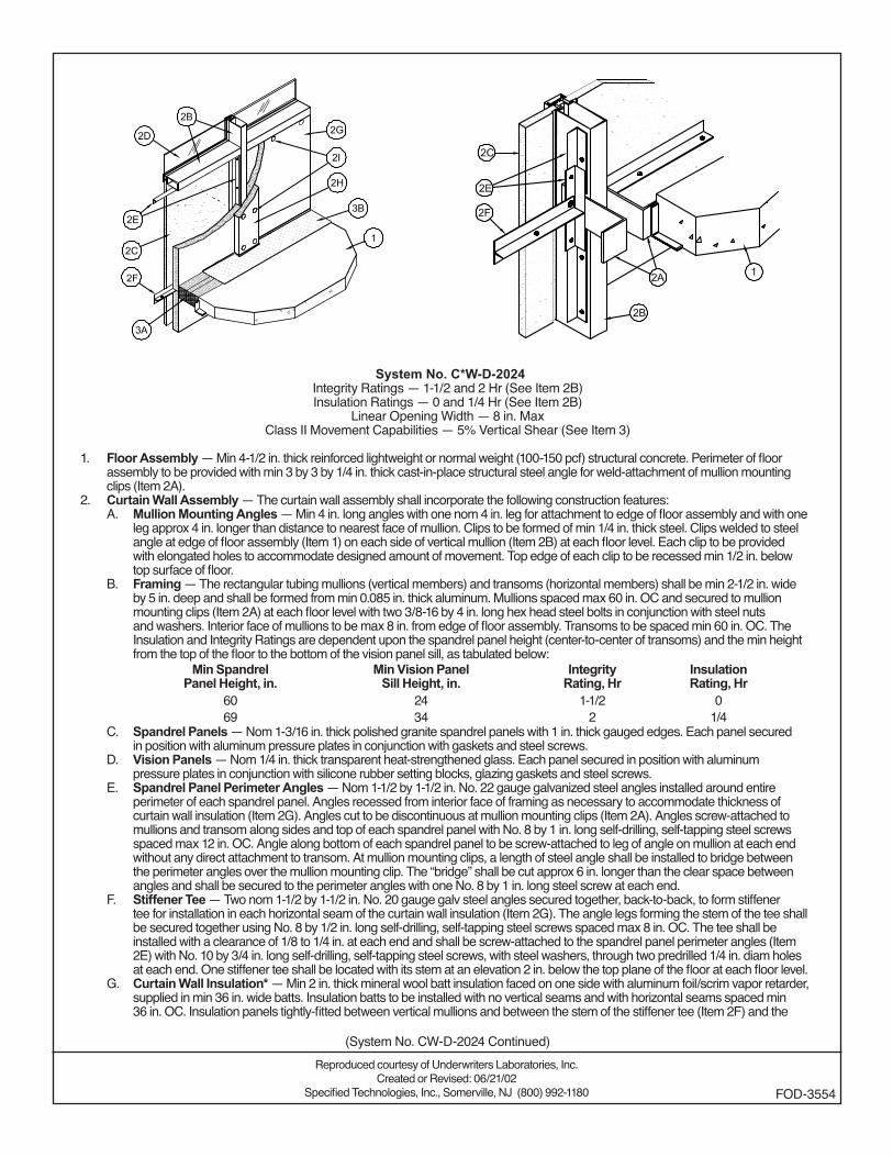
System No. CW-D-2024Integrity Ratings — 1-1/2 and 2 Hr (See Item 2B)Insulation Ratings — 0 and 1/4 Hr (See Item 2B)
Linear Opening Width — 8 in. MaxClass II Movement Capabilities — 5% Vertical Shear (See Item 3)
1. Floor Assembly — Min 4-1/2 in. thick reinforced lightweight or normal weight (100-150 pcf) structural concrete. Perimeter of floor assembly to be provided with min 3 by 3 by 1/4 in. thick cast-in-place structural steel angle for weld-attachment of mullion mounting clips (Item 2A).
2. Curtain Wall Assembly — The curtain wall assembly shall incorporate the following construction features:A. Mullion Mounting Angles — Min 4 in. long angles with one nom 4 in. leg for attachment to edge of floor assembly and with one
leg approx 4 in. longer than distance to nearest face of mullion. Clips to be formed of min 1/4 in. thick steel. Clips welded to steel angle at edge of floor assembly (Item 1) on each side of vertical mullion (Item 2B) at each floor level. Each clip to be provided with elongated holes to accommodate designed amount of movement. Top edge of each clip to be recessed min 1/2 in. below top surface of floor.
B. Framing — The rectangular tubing mullions (vertical members) and transoms (horizontal members) shall be min 2-1/2 in. wide by 5 in. deep and shall be formed from min 0.085 in. thick aluminum. Mullions spaced max 60 in. OC and secured to mullion mounting clips (Item 2A) at each floor level with two 3/8-16 by 4 in. long hex head steel bolts in conjunction with steel nuts and washers. Interior face of mullions to be max 8 in. from edge of floor assembly. Transoms to be spaced min 60 in. OC. The Insulation and Integrity Ratings are dependent upon the spandrel panel height (center-to-center of transoms) and the min height from the top of the floor to the bottom of the vision panel sill, as tabulated below:
Min SpandrelPanel Height, in.
Min Vision PanelSill Height, in.
IntegrityRating, Hr
InsulationRating, Hr
60 24 1-1/2 069 34 2 1/4
C. Spandrel Panels — Nom 1-3/16 in. thick polished granite spandrel panels with 1 in. thick gauged edges. Each panel secured in position with aluminum pressure plates in conjunction with gaskets and steel screws.
D. Vision Panels — Nom 1/4 in. thick transparent heat-strengthened glass. Each panel secured in position with aluminum pressure plates in conjunction with silicone rubber setting blocks, glazing gaskets and steel screws.
E. Spandrel Panel Perimeter Angles — Nom 1-1/2 by 1-1/2 in. No. 22 gauge galvanized steel angles installed around entire perimeter of each spandrel panel. Angles recessed from interior face of framing as necessary to accommodate thickness of curtain wall insulation (Item 2G). Angles cut to be discontinuous at mullion mounting clips (Item 2A). Angles screw-attached to mullions and transom along sides and top of each spandrel panel with No. 8 by 1 in. long self-drilling, self-tapping steel screws spaced max 12 in. OC. Angle along bottom of each spandrel panel to be screw-attached to leg of angle on mullion at each end without any direct attachment to transom. At mullion mounting clips, a length of steel angle shall be installed to bridge between the perimeter angles over the mullion mounting clip. The “bridge” shall be cut approx 6 in. longer than the clear space between angles and shall be secured to the perimeter angles with one No. 8 by 1 in. long steel screw at each end.
F. Stiffener Tee — Two nom 1-1/2 by 1-1/2 in. No. 20 gauge galv steel angles secured together, back-to-back, to form stiffener tee for installation in each horizontal seam of the curtain wall insulation (Item 2G). The angle legs forming the stem of the tee shall be secured together using No. 8 by 1/2 in. long self-drilling, self-tapping steel screws spaced max 8 in. OC. The tee shall be installed with a clearance of 1/8 to 1/4 in. at each end and shall be screw-attached to the spandrel panel perimeter angles (Item 2E) with No. 10 by 3/4 in. long self-drilling, self-tapping steel screws, with steel washers, through two predrilled 1/4 in. diam holes at each end. One stiffener tee shall be located with its stem at an elevation 2 in. below the top plane of the floor at each floor level.
G. Curtain Wall Insulation* — Min 2 in. thick mineral wool batt insulation faced on one side with aluminum foil/scrim vapor retarder, supplied in min 36 in. wide batts. Insulation batts to be installed with no vertical seams and with horizontal seams spaced min 36 in. OC. Insulation panels tightly-fitted between vertical mullions and between the stem of the stiffener tee (Item 2F) and the
Reproduced courtesy of Underwriters Laboratories, Inc.Created or Revised: 06/21/02
Specified Technologies, Inc., Somerville, NJ (800) 992-1180 FOD-3554
(System No. CW-D-2024 Continued)

transom, flush with the interior surface of framing. Insulation panels secured to spandrel panel perimeter angles and to each stiffener tee with cup head weld pins (Item 2I) spaced max 12 in OC. The horizontal seam between insulation panels shall be located 2 in. below the top plane of the floor at each floor level.
OWENS CORNING HT INC, DIV OF OWENS CORNING — CW-8H. Framing Covers — Curtain Wall Insulation* — Min 1 in. thick mineral wool batt insulation faced on one side with aluminum
foil/scrim vapor retarder, supplied in min 24 by 48 in. boards. Nom 8 in. wide strips to be centered over mullions and secured to the spandrel panel perimeter angles with cup head weld pins (Item 2I) spaced max 12 in. OC. Where more than one spandrel panel occurs between vertically separated vision panels, the horizontal transom between spandrel panels shall also be covered with an 8 in. wide framing cover in the same manner as on the vertical mullions. Framing covers on mullions to abut the mineral wool batt safing material (Item 3A) above and below floor.
OWENS CORNING HT INC, DIV OF OWENS CORNING — CW-8I. Weld Pin — No. 12 gauge galv steel weld pin with nom 1-3/16 in. diam galv steel cup head. Cup head weld pins provided in
two lengths. One length to be equal to thickness of curtain wall insulation (Item 2G) and second length to be equal to thickness of curtain wall insulation plus thickness of framing cover (Item 2H). Cup head weld pins inserted through curtain wall insulation and mullion covers and welded to spandrel panel perimeter angles max 12 in. OC.
J. Steel Screw And Clinch Shield — (Not Shown) — As an alternate to the weld pins (Item 2I), self-drilling, self-tapping steel screws with min 1-1/2 in. diam galv steel clinch shields may be used to secure the curtain wall insulation and framing covers. Steel screws provided in two lengths. One length to be 1/2 in. greater than thickness of curtain wall insulation (Item 2G) and second length to be 1/2 in. greater than thickness of curtain wall insulation plus thickness of framing cover (Item 2H). Screws secured to spandrel panel perimeter angles, through curtain wall insulation and mullion covers, and spaced max 12 in. OC.
3. Safing System — Max separation between edge of floor assembly and face of framing members (at time of installation) is 8 in. The safing system is designed to accommodate vertical shear movement up to a max of 5 percent of its installed width. The safing system shall incorporate the following construction features:A. Forming Material* — Nom 4 pcf density mineral wool batt insulation. Batt sections cut to a min 4-1/2 in. width and stacked to
a thickness which is min 20 percent greater than the width of linear gap between the curtain wall insulation and the edge of the concrete floor slab. The forming material is compressed and inserted cut-edge-first into linear gap such that its top surface is flush with the top surface of the floor assembly. A max of one tightly-butted seam is permitted between mullions. Additional pieces of forming material to be friction-fit into spaces between mullion mounting clips at each mullion location.
OWENS CORNING HT INC, DIV OF OWENS CORNING — Safing Insulation/MWB. Fill, Void or Cavity Material* — Min 1/8 in. wet thickness (min 1/16 in. dry thickness) of fill material spray-applied over top of
forming material and lapping min 1/2 in. onto the top surface of the floor and onto the curtain wall insulation and framing covers. SPECIFIED TECHNOLOGIES INC — SpecSeal AS200 Elastomeric Spray
*Bearing the UL Classification Mark
(System No. CW-D-2024 Continued)
Reproduced courtesy of Underwriters Laboratories, Inc.Created or Revised: 06/21/02
Specified Technologies, Inc., Somerville, NJ (800) 992-1180 FOD-3554
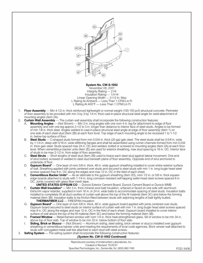
System No. CW-S-1002November 08, 2001
Integrity Rating — 2 HrInsulation Rating — 1/4 Hr
Linear Opening Width — 2-1/2 In. MaxL Rating At Ambient — Less Than 1 CFM/Lin FtL Rating At 400°F — Less Than 1 CFM/Lin Ft
1. Floor Assembly — Min 4-1/2 in. thick reinforced lightweight or normal weight (100-150 pcf) structural concrete. Perimeter of fl oor assembly to be provided with min 3 by 3 by 1/4 in. thick cast-in-place structural steel angle for weld-attachment of mounting angles (Item 2A).
2. Curtain Wall Assembly — The curtain wall assembly shall incorporate the following construction features:A. Mounting Angles — (Not Shown) — Min 3 in. long angles with one nom 4 in. leg for attachment to edge of fl oor
assembly and with one leg approx 2-1/2 to 3 in. longer than distance to interior face of steel studs. Angles to be formed of min 1/8 in. thick steel. Angles welded to cast-in-place structural steel angle at edge of fl oor assembly (Item 1) on one side of each steel stud (Item 2B) at each fl oor level. Top edge of each mounting angle to be recessed 1 to 1-1/2 in. below top surface of fl oor.
B. Steel Studs — C-shaped studs formed from min 0.034 in. thick (20 ga) galv steel. The steel studs shall be 3-5/8 in. wide by 1-1/4 in. deep with 5/16 in. wide stiffening fl anges and shall be assembled using runner channels formed from min 0.034 in. thick galv steel. Studs spaced max 24 in. OC and welded, bolted or screwed to mounting angles (Item 2A) at each fl oor level. When cementitious backer units (Item 2E) are used for exterior sheathing, max stud spacing is 16 in. OC. Interior face of studs to be max 2-1/2 in. from edge of fl oor assembly.
C. Steel Struts — Short lengths of steel stud (Item 2B) used to brace each steel stud against lateral movement. One end of strut bolted, screwed or welded to steel stud beneath plane of fl oor assembly. Opposite end of strut anchored to underside of fl oor.
D. Gypsum Board* — One layer of nom 5/8 in. thick, 48 in. wide gypsum sheathing installed to cover entire exterior surface of wall. Sheathing applied with joints centered over studs and secured to steel studs with min 1 in. long bugle head steel screws spaced max 8 in. OC along the edges and max 12 in. OC in the fi eld of each sheet.
E. Cementitious Backer Units* — As an alternate to the gypsum sheathing (Item 2D), nom 1/2 in. or 5/8 in. thick square-edge boards attached to studs with 1-1/4 in. long corrosion resistant self-tapping wafer-head steel screws spaced 6 in OC. Joints covered with glass fi ber mesh tape.
UNITED STATES GYPSUM CO — Durock Exterior Cement Board, Durock Cement Board or Durock WMBF. Curtain Wall Insulation* — Min 3 in. thick mineral wool batt insulation, unfaced or faced on one side with aluminum
foil/scrim vapor retarder, supplied in nom 16 in. or 24 in. wide batts to accommodate spacing of steel studs. Insulation batts installed to completely fi ll all stud cavities of curtain wall above the top of the fi ll material (Item 3C) and below the forming material (Item 3B). Insulation batts to be friction-fi tted between studs with adjoining lengths of batt tightly butted.
THERMAFIBER LLC — FIRESPAN InsulationG. Gypsum Board* — One layer of nom 5/8 in. thick, 48 in. wide gypsum board applied with joints centered over studs.
Gypsum board secured to steel studs on interior surface of curtain wall with min 1 in. long bugle head steel screws spaced max 8 in. OC along the edges and max 12 in. OC in the fi eld of each sheet. Gypsum board installed to cover interior surface of wall above the top of the fi ll material (Item 3C) and below the forming material (Item 3B).
H. Framed Window — Metal-framed window with nom 1/4 in. thick heat-strengthened glass. Sill of window to be min 34 in. above top of fl oor slab. Top of window to be min 33 in. below bottom of fl oor slab.
I. Siding, Brick or Stucco — (Not Shown) — Aluminum siding, steel siding, brick veneer or stucco installed over gypsum sheathing or cementitious backer units and meeting the requirements of local code agencies. Brick veneer wall attached to studs with corrugated metal wall ties attached to each stud with steel screws.
3. Safi ng System — The safi ng system shall incorporate the following construction features:
Reproduced courtesy of Underwriters Laboratories, Inc.Created or Revised: 10/25/01
Specifi ed Technologies, Inc., Somerville, NJ (800) 992-1180 FOD-3406
(System No. CW-S-1002 Continued)
A. Forming Material* — Nom 4 pcf density mineral wool batt insulation. Batt sections to be cut to a min 4-1/2 in. width. and stacked to a thickness which is 20 percent greater than the width of linear gap between the gypsum sheathing and the edge of the concrete fl oor. The forming material is compressed and inserted cut-edge-fi rst into linear gap between edge of fl oor slab and sheathing material such that its top surface is fl ush with the top surface of the fl oor assembly. Length of batt to be equal to on-center spacing of steel studs such that it is friction-fi tted between studs and mounting angles without seams. Additional pieces of mineral wool batt to be stuffed inside the channel of each steel stud throughout the thickness of the forming material.
THERMAFIBER LLC — SAFB. Fill, Void or Cavity Material* — Min 1/8 in. wet thickness (min 1/16 in. dry) of fi ll material spray-applied over top of forming
material and lapping min 1/2 in. onto the top surface of the fl oor and onto the gypsum sheathing and steel studs. SPECIFIED TECHNOLOGIES INC — SpecSeal AS200 Elastomeric Spray
*Bearing the UL Classifi cation Mark
(System No. CW-S-1002 Continued)
Reproduced courtesy of Underwriters Laboratories, Inc.Created or Revised: 10/25/01
Specifi ed Technologies, Inc., Somerville, NJ (800) 992-1180 FOD-3406

System No. CW-S-1003November 08, 2001
Integrity Rating — 2 HrInsulation Rating — 1/4 Hr
Linear Opening Width — 2-1/2 In. MaxL Rating At Ambient — Less Than 1 CFM/Lin Ft
L Rating At 400 F — Less Than 1 CFM/Lin Ft
1. Floor Assembly — Min 4-1/2 in. thick reinforced lightweight or normal weight (100-150 pcf) structural concrete. Perimeter of fl oor assembly to be provided with min 3 by 3 by 1/4 in. thick cast-in-place structural steel angle for weld-attachment of mounting angles (Item 2A).
2. Curtain Wall Assembly — The curtain wall assembly shall incorporate the following construction features:A. Mounting Angles — (Not Shown) — Min 3 in. long angles with one nom 4 in. leg for attachment to edge of fl oor
assembly and with one leg approx 2-1/2 to 3 in. longer than distance to interior face of steel studs. Angles to be formed of min 1/8 in. thick steel. Angles welded to cast-in-place structural steel angle at edge of fl oor assembly (Item 1) on one side of each steel stud (Item 2B) at each fl oor level. Top edge of each mounting angle to be recessed 1 to 1-1/2 in. below top surface of fl oor.
B. Steel Studs — C-shaped studs formed from min 0.034 in. thick (20 ga) galv steel. The steel studs shall be 3-5/8 in. wide by 1-1/4 in. deep with 5/16 in. wide stiffening fl anges and shall be assembled using runner channels formed from min 0.034 in. thick galv steel. Studs spaced max 24 in. OC and welded, bolted or screwed to mounting angles (Item 2A) at each fl oor level. When cementitious backer units (Item 2E) are used for exterior sheathing, max stud spacing is 16 in. OC. Interior face of studs to be max 2-1/2 in. from edge of fl oor assembly.
C. Steel Struts — Short lengths of steel stud (Item 2B) used to brace each steel stud against lateral movement. One end of strut bolted, screwed or welded to steel stud beneath plane of fl oor assembly. Opposite end of strut anchored to underside of fl oor.
D. Gypsum Board* — One layer of nom 5/8 in. thick, 48 in. wide gypsum sheathing installed to cover entire exterior surface of wall. Sheathing applied with joints centered over studs and secured to steel studs with min 1 in. long bugle head steel screws spaced max 8 in. OC along the edges and max 12 in. OC in the fi eld of each sheet.
E. Cementitious Backer Units* — As an alternate to the gypsum sheathing (Item 2D), nom 1/2 in. or 5/8 in. thick square-edge boards attached to studs with 1-1/4 in. long corrosion resistant self-tapping wafer-head steel screws spaced 6 in OC. Joints covered with glass fi ber mesh tape.
UNITED STATES GYPSUM CO — Durock Exterior Cement Board, Durock Cement Board or Durock WMBF. Batts and Blankets* — Any glass fi ber insulation bearing the UL Classifi cation Marking as to fi re resistance or surface
burning characteristics, of a thickness to completely fi ll stud cavity. Insulation batts friction fi t to completely fi ll all stud cavities of curtain wall above the top of the fi ll material (Item B) and below the forming material (Item 3A).
See Batts and Blankets (BZJZ) category for names of manufacturers.G. Gypsum Board* — One layer of nom 5/8 in. thick, 48 in. wide gypsum board applied with joints centered over studs.
Gypsum board secured to steel studs on interior surface of curtain wall with min 1 in. long bugle head steel screws spaced max 8 in. OC along the edges and max 12 in. OC in the fi eld of each sheet. Gypsum board installed to cover interior surface of wall above the top of the fi ll material (Item 3C) and below the forming material (Item 3B).
H. Framed Window — Metal-framed window with nom 1/4 in. thick heat-strengthened glass. Sill of window to be min 34 in. above top of fl oor slab. Top of window to be min 33 in. below bottom of fl oor slab.
I. Siding, Brick or Stucco — (Not Shown) — Aluminum siding, steel siding, brick veneer or stucco installed over gypsum sheathing or cementitious backer units and meeting the requirements of local code agencies. Brick veneer wall attached to studs with corrugated metal wall ties attached to each stud with steel screws.
3. Safi ng System — The safi ng system shall incorporate the following construction features:
Reproduced courtesy of Underwriters Laboratories, Inc.Created or Revised: 12/03/01
Specifi ed Technologies, Inc., Somerville, NJ (800) 992-1180 FOD-3228
(System No. CW-S-1003 Continued)
A. Forming Material* — Nom 4 pcf density mineral wool batt insulation. Batt sections to be cut to a min width of 4 in. and stacked to a thickness which is 20 percent greater than the width of linear gap between the gypsum sheathing and the edge of the concrete fl oor. The forming material is compressed and inserted cut-edge-fi rst into linear gap between edge of fl oor slab and sheathing material such that its top surface is fl ush with the top surface of the fl oor assembly. Length of batt to be equal to on-center spacing of steel studs such that it is friction-fi tted between studs and mounting angles without seams. Additional pieces of mineral wool batt to be stuffed inside the channel of each steel stud throughout the thickness of the forming material.
THERMAFIBER LLC — SAFB. Fill, Void or Cavity Material* — Min 1/8 in. wet thickness (min 1/16 in. dry) of fi ll material spray-applied over top of forming
material and lapping min 1/2 in. onto the top surface of the fl oor and onto the gypsum sheathing and steel studs. SPECIFIED TECHNOLOGIES INC — SpecSeal AS200 Elastomeric Spray
*Bearing the UL Classifi cation Mark
(System No. CW-S-1003 Continued)
FOD-3228
Reproduced courtesy of Underwriters Laboratories, Inc.Created or Revised: 12/03/01
Specifi ed Technologies, Inc., Somerville, NJ (800) 992-1180
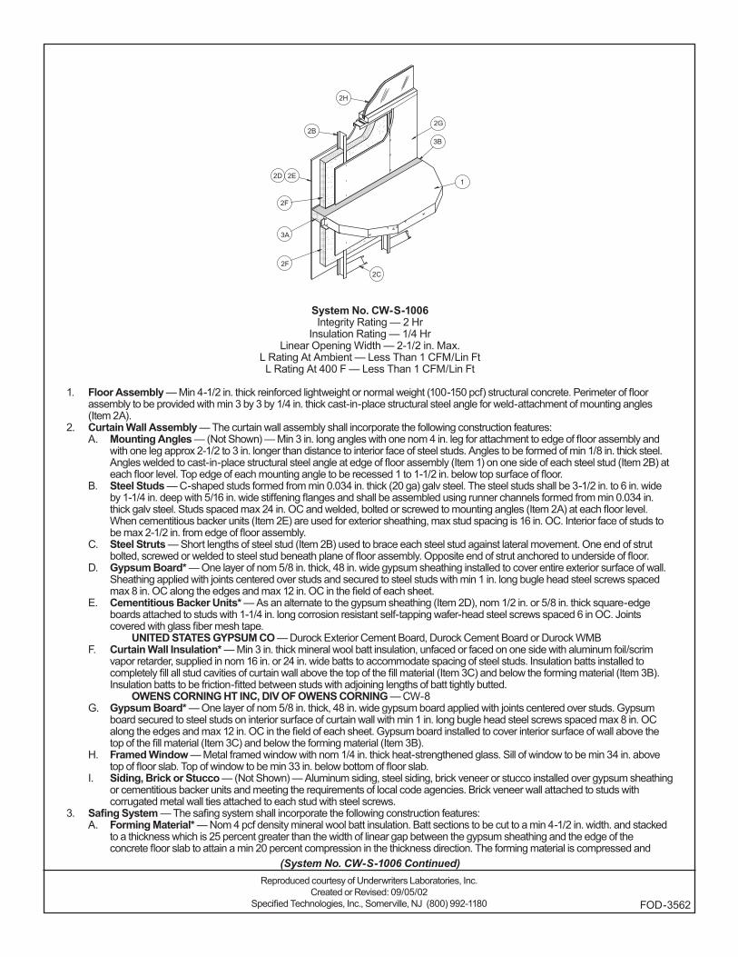
System No. CW-S-1006Integrity Rating — 2 Hr
Insulation Rating — 1/4 HrLinear Opening Width — 2-1/2 in. Max.
L Rating At Ambient — Less Than 1 CFM/Lin FtL Rating At 400 F — Less Than 1 CFM/Lin Ft
1. Floor Assembly — Min 4-1/2 in. thick reinforced lightweight or normal weight (100-150 pcf) structural concrete. Perimeter of floor assembly to be provided with min 3 by 3 by 1/4 in. thick cast-in-place structural steel angle for weld-attachment of mounting angles (Item 2A).
2. Curtain Wall Assembly — The curtain wall assembly shall incorporate the following construction features: A. Mounting Angles — (Not Shown) — Min 3 in. long angles with one nom 4 in. leg for attachment to edge of floor assembly and
with one leg approx 2-1/2 to 3 in. longer than distance to interior face of steel studs. Angles to be formed of min 1/8 in. thick steel. Angles welded to cast-in-place structural steel angle at edge of floor assembly (Item 1) on one side of each steel stud (Item 2B) at each floor level. Top edge of each mounting angle to be recessed 1 to 1-1/2 in. below top surface of floor.
B. Steel Studs — C-shaped studs formed from min 0.034 in. thick (20 ga) galv steel. The steel studs shall be 3-1/2 in. to 6 in. wide by 1-1/4 in. deep with 5/16 in. wide stiffening flanges and shall be assembled using runner channels formed from min 0.034 in. thick galv steel. Studs spaced max 24 in. OC and welded, bolted or screwed to mounting angles (Item 2A) at each floor level. When cementitious backer units (Item 2E) are used for exterior sheathing, max stud spacing is 16 in. OC. Interior face of studs to be max 2-1/2 in. from edge of floor assembly.
C. Steel Struts — Short lengths of steel stud (Item 2B) used to brace each steel stud against lateral movement. One end of strut bolted, screwed or welded to steel stud beneath plane of floor assembly. Opposite end of strut anchored to underside of floor.
D. Gypsum Board* — One layer of nom 5/8 in. thick, 48 in. wide gypsum sheathing installed to cover entire exterior surface of wall. Sheathing applied with joints centered over studs and secured to steel studs with min 1 in. long bugle head steel screws spaced max 8 in. OC along the edges and max 12 in. OC in the field of each sheet.
E. Cementitious Backer Units* — As an alternate to the gypsum sheathing (Item 2D), nom 1/2 in. or 5/8 in. thick square-edge boards attached to studs with 1-1/4 in. long corrosion resistant self-tapping wafer-head steel screws spaced 6 in OC. Joints covered with glass fiber mesh tape.
UNITED STATES GYPSUM CO — Durock Exterior Cement Board, Durock Cement Board or Durock WMBF. Curtain Wall Insulation* — Min 3 in. thick mineral wool batt insulation, unfaced or faced on one side with aluminum foil/scrim
vapor retarder, supplied in nom 16 in. or 24 in. wide batts to accommodate spacing of steel studs. Insulation batts installed to completely fill all stud cavities of curtain wall above the top of the fill material (Item 3C) and below the forming material (Item 3B). Insulation batts to be friction-fitted between studs with adjoining lengths of batt tightly butted.
OWENS CORNING HT INC, DIV OF OWENS CORNING — CW-8G. Gypsum Board* — One layer of nom 5/8 in. thick, 48 in. wide gypsum board applied with joints centered over studs. Gypsum
board secured to steel studs on interior surface of curtain wall with min 1 in. long bugle head steel screws spaced max 8 in. OC along the edges and max 12 in. OC in the field of each sheet. Gypsum board installed to cover interior surface of wall above the top of the fill material (Item 3C) and below the forming material (Item 3B).
H. Framed Window — Metal framed window with nom 1/4 in. thick heat-strengthened glass. Sill of window to be min 34 in. above top of floor slab. Top of window to be min 33 in. below bottom of floor slab.
I. Siding, Brick or Stucco — (Not Shown) — Aluminum siding, steel siding, brick veneer or stucco installed over gypsum sheathing or cementitious backer units and meeting the requirements of local code agencies. Brick veneer wall attached to studs with corrugated metal wall ties attached to each stud with steel screws.
3. Safing System — The safing system shall incorporate the following construction features: A. Forming Material* — Nom 4 pcf density mineral wool batt insulation. Batt sections to be cut to a min 4-1/2 in. width. and stacked
to a thickness which is 25 percent greater than the width of linear gap between the gypsum sheathing and the edge of the concrete floor slab to attain a min 20 percent compression in the thickness direction. The forming material is compressed and
Reproduced courtesy of Underwriters Laboratories, Inc.Created or Revised: 09/05/02
Specified Technologies, Inc., Somerville, NJ (800) 992-1180 FOD-3562
(System No. CW-S-1006 Continued)
inserted cut-edge-first into linear gap between edge of floor slab and sheathing material such that its top surface is flush with the top surface of the floor assembly. Length of batt to be equal to on-center spacing of steel studs such that it is friction-fitted between studs and mounting angles without seams. Additional pieces of mineral wool batt to be stuffed inside the channel of each steel stud throughout the thickness of the forming material.
OWENS CORNING HT INC, DIV OF OWENS CORNING — Safing Insulation/MWB. Fill, Void or Cavity Material* — Min 1/8 in. wet thickness (min 1/16 in. dry) of fill material spray-applied over top of forming
material and lapping min 1/2 in. onto the top surface of the floor and onto the gypsum sheathing and steel studs. SPECIFIED TECHNOLOGIES INC — SpecSeal AS200 Elastomeric Spray
*Bearing the UL Classification Mark
(System No. CW-S-1006 Continued)
FOD-3562
Reproduced courtesy of Underwriters Laboratories, Inc.Created or Revised: 09/05/02
Specified Technologies, Inc., Somerville, NJ (800) 992-1180
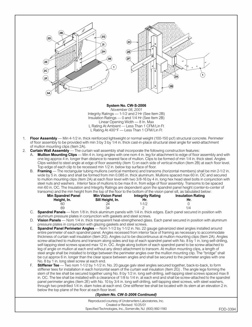
System No. CW-S-2006November 08, 2001
Integrity Ratings — 1-1/2 and 2 Hr (See Item 2B) Insulation Ratings — 0 and 1/4 Hr (See Item 2B)
Linear Opening Width — 8 In. MaxL Rating At Ambient — Less Than 1 CFM/Lin FtL Rating At 400°F — Less Than 1 CFM/Lin Ft
1. Floor Assembly — Min 4-1/2 in. thick reinforced lightweight or normal weight (100-150 pcf) structural concrete. Perimeter of fl oor assembly to be provided with min 3 by 3 by 1/4 in. thick cast-in-place structural steel angle for weld-attachment of mullion mounting clips (Item 2A).
2. Curtain Wall Assembly — The curtain wall assembly shall incorporate the following construction features:A. Mullion Mounting Clips — Min 4 in. long angles with one nom 4 in. leg for attachment to edge of fl oor assembly and with
one leg approx 4 in. longer than distance to nearest face of mullion. Clips to be formed of min 1/4 in. thick steel. Angles Clips welded to steel angle at edge of fl oor assembly (Item 1) on each side of vertical mullion (Item 2B) at each fl oor level. Top edge of each clip to be recessed min 1/2 in. below top surface of fl oor.
B. Framing — The rectangular tubing mullions (vertical members) and transoms (horizontal members) shall be min 2-1/2 in. wide by 5 in. deep and shall be formed from min 0.085 in. thick aluminum. Mullions spaced max 60 in. OC and secured to mullion mounting clips (Item 2A) at each fl oor level with two 3/8-16 by 4 in. long hex head steel bolts in conjunction with steel nuts and washers . Interior face of mullions to be max 8 in. from edge of fl oor assembly. Transoms to be spaced min 60 in. OC. The Insulation and Integrity Ratings are dependent upon the spandrel panel height (center-to-center of transoms) and the min height from the top of the fl oor to the bottom of the vision panel sill, as tabulated below:
Min Spandrel Panel Min Vision Panel Integrity Rating Insulation Rating Height, In. Sill Height, In. Hr. Hr. 60 24 1-1/2 0 69 34 2 1/4C. Spandrel Panels — Nom 1/8 in. thick aluminum panels with 1/4 in. thick edges. Each panel secured in position with
aluminum pressure plates in conjunction with gaskets and steel screws.D. Vision Panels — Nom 1/4 in. thick transparent heat-strengthened glass. Each panel secured in position with aluminum
pressure plates in conjunction with glazing gaskets and steel screws.E. Spandrel Panel Perimeter Angles — Nom 1-1/2 by 1-1/2 in. No. 22 gauge galvanized steel angles installed around
entire perimeter of each spandrel panel. Angles recessed from interior face of framing as necessary to accommodate thickness of curtain wall insulation (Item 2G). Angles cut to be discontinuous at mullion mounting clips (Item 2A). Angles screw-attached to mullions and transom along sides and top of each spandrel panel with No. 8 by 1 in. long self-drilling, self-tapping steel screws spaced max 12 in. OC. Angle along bottom of each spandrel panel to be screw-attached to leg of angle on mullion at each end without any direct attachment to transom. At mullion mounting clips, a length of steel angle shall be installed to bridge between the perimeter angles over the mullion mounting clip. The “bridge” shall be cut approx 6 in. longer than the clear space between angles and shall be secured to the perimeter angles with one No. 8 by 1 in. long steel screw at each end.
F. Stiffener Tee — Two nom 1-1/2 by 1-1/2 in. No. 20 gauge galv steel angles secured together, back-to-back, to form stiffener tees for installation in each horizontal seam of the curtain wall insulation (Item 2G) . The angle legs forming the stem of the tee shall be secured together using No. 8 by 1/2 in. long self-drilling, self-tapping steel screws spaced max 8 in. OC. The tee shall be installed with a clearance of 1/8 to 1/4 in. at each end and shall be screw-attached to the spandrel panel perimeter angles (Item 2E) with No. 10 by 3/4 in. long self-drilling, self-tapping steel screws, with steel washers, through two predrilled 1/4 in. diam holes at each end. One stiffener tee shall be located with its stem at an elevation 2 in. below the top plane of the fl oor at each fl oor level.
(System No. CW-S-2006 Continued)
Reproduced courtesy of Underwriters Laboratories, Inc.Created or Revised: 10/25/01
Specifi ed Technologies, Inc., Somerville, NJ (800) 992-1180 FOD-3394
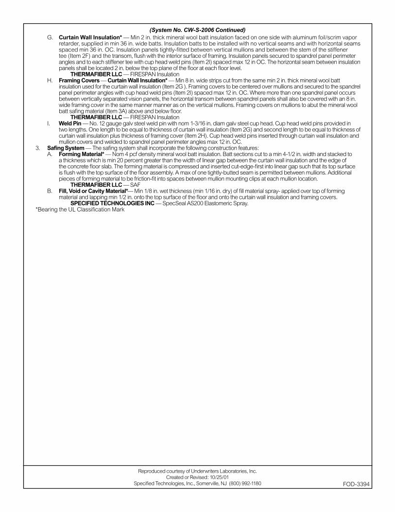
G. Curtain Wall Insulation* — Min 2 in. thick mineral wool batt insulation faced on one side with aluminum foil/scrim vapor retarder, supplied in min 36 in. wide batts. Insulation batts to be installed with no vertical seams and with horizontal seams spaced min 36 in. OC. Insulation panels tightly-fi tted between vertical mullions and between the stem of the stiffener tee (Item 2F) and the transom, fl ush with the interior surface of framing. Insulation panels secured to spandrel panel perimeter angles and to each stiffener tee with cup head weld pins (Item 2I) spaced max 12 in OC. The horizontal seam between insulation panels shall be located 2 in. below the top plane of the fl oor at each fl oor level.
THERMAFIBER LLC — FIRESPAN InsulationH. Framing Covers — Curtain Wall Insulation* — Min 8 in. wide strips cut from the same min 2 in. thick mineral wool batt
insulation used for the curtain wall insulation (Item 2G ). Framing covers to be centered over mullions and secured to the spandrel panel perimeter angles with cup head weld pins (Item 2I) spaced max 12 in. OC. Where more than one spandrel panel occurs between vertically separated vision panels, the horizontal transom between spandrel panels shall also be covered with an 8 in. wide framing cover in the same manner manner as on the vertical mullions. Framing covers on mullions to abut the mineral wool batt safi ng material (Item 3A) above and below fl oor.
THERMAFIBER LLC — FIRESPAN InsulationI. Weld Pin — No. 12 gauge galv steel weld pin with nom 1-3/16 in. diam galv steel cup head. Cup head weld pins provided in
two lengths. One length to be equal to thickness of curtain wall insulation (Item 2G) and second length to be equal to thickness of curtain wall insulation plus thickness of framing cover (Item 2H). Cup head weld pins inserted through curtain wall insulation and mullion covers and welded to spandrel panel perimeter angles max 12 in. OC.
3. Safi ng System — The safi ng system shall incorporate the following construction features:A. Forming Material* — Nom 4 pcf density mineral wool batt insulation. Batt sections cut to a min 4-1/2 in. width and stacked to
a thickness which is min 20 percent greater than the width of linear gap between the curtain wall insulation and the edge of the concrete fl oor slab. The forming material is compressed and inserted cut-edge-fi rst into linear gap such that its top surface is fl ush with the top surface of the fl oor assembly. A max of one tightly-butted seam is permitted between mullions. Additional pieces of forming material to be friction-fi t into spaces between mullion mounting clips at each mullion location.
THERMAFIBER LLC — SAFB. Fill, Void or Cavity Material*— Min 1/8 in. wet thickness (min 1/16 in. dry) of fi ll material spray- applied over top of forming
material and lapping min 1/2 in. onto the top surface of the fl oor and onto the curtain wall insulation and framing covers. SPECIFIED TECHNOLOGIES INC — SpecSeal AS200 Elastomeric Spray.
*Bearing the UL Classifi cation Mark
(System No. CW-S-2006 Continued)
Reproduced courtesy of Underwriters Laboratories, Inc.Created or Revised: 10/25/01
Specifi ed Technologies, Inc., Somerville, NJ (800) 992-1180 FOD-3394
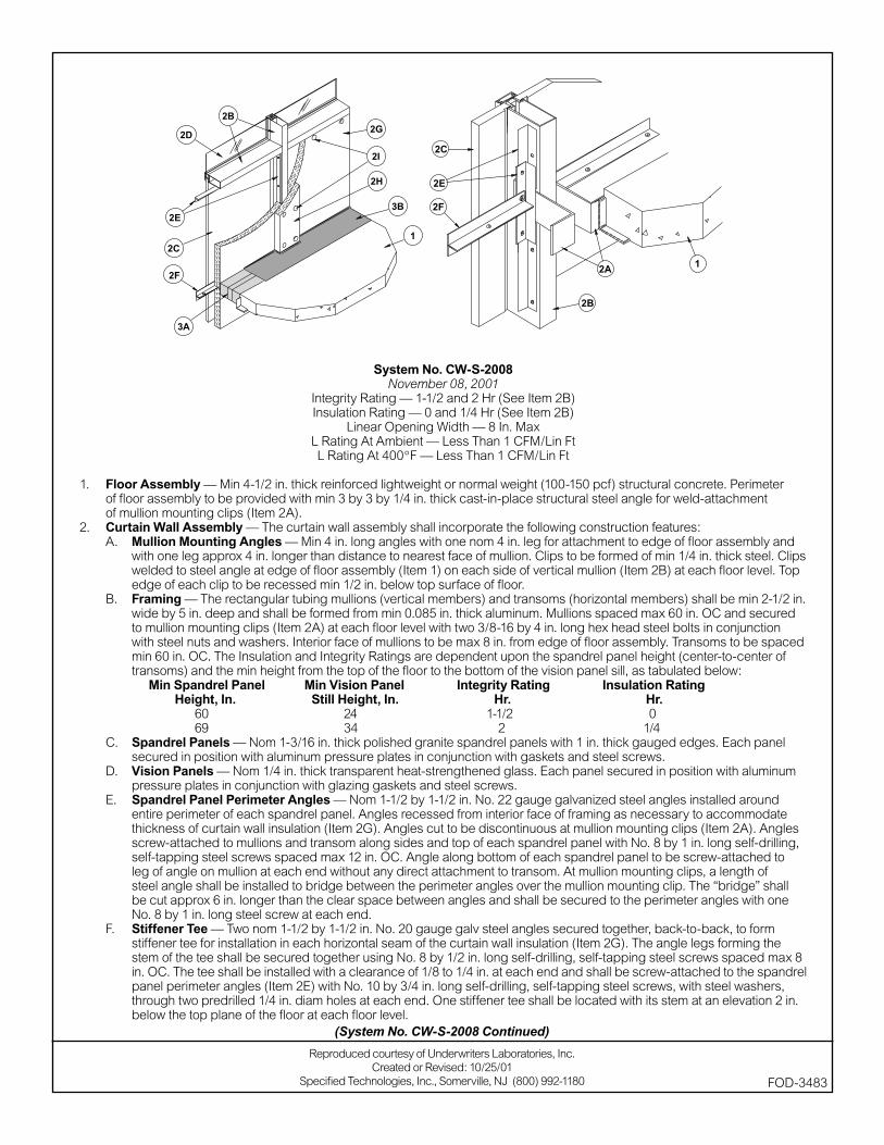
System No. CW-S-2008November 08, 2001
Integrity Rating — 1-1/2 and 2 Hr (See Item 2B)Insulation Rating — 0 and 1/4 Hr (See Item 2B)
Linear Opening Width — 8 In. MaxL Rating At Ambient — Less Than 1 CFM/Lin FtL Rating At 400°F — Less Than 1 CFM/Lin Ft
1. Floor Assembly — Min 4-1/2 in. thick reinforced lightweight or normal weight (100-150 pcf) structural concrete. Perimeter of fl oor assembly to be provided with min 3 by 3 by 1/4 in. thick cast-in-place structural steel angle for weld-attachment of mullion mounting clips (Item 2A).
2. Curtain Wall Assembly — The curtain wall assembly shall incorporate the following construction features:A. Mullion Mounting Angles — Min 4 in. long angles with one nom 4 in. leg for attachment to edge of fl oor assembly and
with one leg approx 4 in. longer than distance to nearest face of mullion. Clips to be formed of min 1/4 in. thick steel. Clips welded to steel angle at edge of fl oor assembly (Item 1) on each side of vertical mullion (Item 2B) at each fl oor level. Top edge of each clip to be recessed min 1/2 in. below top surface of fl oor.
B. Framing — The rectangular tubing mullions (vertical members) and transoms (horizontal members) shall be min 2-1/2 in. wide by 5 in. deep and shall be formed from min 0.085 in. thick aluminum. Mullions spaced max 60 in. OC and secured to mullion mounting clips (Item 2A) at each fl oor level with two 3/8-16 by 4 in. long hex head steel bolts in conjunction with steel nuts and washers. Interior face of mullions to be max 8 in. from edge of fl oor assembly. Transoms to be spaced min 60 in. OC. The Insulation and Integrity Ratings are dependent upon the spandrel panel height (center-to-center of transoms) and the min height from the top of the fl oor to the bottom of the vision panel sill, as tabulated below:
Min Spandrel Panel Min Vision Panel Integrity Rating Insulation Rating Height, In. Still Height, In. Hr. Hr. 60 24 1-1/2 0 69 34 2 1/4C. Spandrel Panels — Nom 1-3/16 in. thick polished granite spandrel panels with 1 in. thick gauged edges. Each panel
secured in position with aluminum pressure plates in conjunction with gaskets and steel screws.D. Vision Panels — Nom 1/4 in. thick transparent heat-strengthened glass. Each panel secured in position with aluminum
pressure plates in conjunction with glazing gaskets and steel screws.E. Spandrel Panel Perimeter Angles — Nom 1-1/2 by 1-1/2 in. No. 22 gauge galvanized steel angles installed around
entire perimeter of each spandrel panel. Angles recessed from interior face of framing as necessary to accommodate thickness of curtain wall insulation (Item 2G). Angles cut to be discontinuous at mullion mounting clips (Item 2A). Angles screw-attached to mullions and transom along sides and top of each spandrel panel with No. 8 by 1 in. long self-drilling, self-tapping steel screws spaced max 12 in. OC. Angle along bottom of each spandrel panel to be screw-attached to leg of angle on mullion at each end without any direct attachment to transom. At mullion mounting clips, a length of steel angle shall be installed to bridge between the perimeter angles over the mullion mounting clip. The “bridge” shall be cut approx 6 in. longer than the clear space between angles and shall be secured to the perimeter angles with one No. 8 by 1 in. long steel screw at each end.
F. Stiffener Tee — Two nom 1-1/2 by 1-1/2 in. No. 20 gauge galv steel angles secured together, back-to-back, to form stiffener tee for installation in each horizontal seam of the curtain wall insulation (Item 2G). The angle legs forming the stem of the tee shall be secured together using No. 8 by 1/2 in. long self-drilling, self-tapping steel screws spaced max 8 in. OC. The tee shall be installed with a clearance of 1/8 to 1/4 in. at each end and shall be screw-attached to the spandrel panel perimeter angles (Item 2E) with No. 10 by 3/4 in. long self-drilling, self-tapping steel screws, with steel washers, through two predrilled 1/4 in. diam holes at each end. One stiffener tee shall be located with its stem at an elevation 2 in. below the top plane of the fl oor at each fl oor level.
(System No. CW-S-2008 Continued)
Reproduced courtesy of Underwriters Laboratories, Inc.Created or Revised: 10/25/01
Specifi ed Technologies, Inc., Somerville, NJ (800) 992-1180 FOD-3483
G. Curtain Wall Insulation* — Min 2 in. thick mineral wool batt insulation faced on one side with aluminum foil/scrim vapor retarder, supplied in min 36 in. wide batts. Insulation batts to be installed with no vertical seams and with horizontal seams spaced min 36 in. OC. Insulation panels tightly-fi tted between vertical mullions and between the stem of the stiffener tee (Item 2F) and the transom, fl ush with the interior surface of framing. Insulation panels secured to spandrel panel perimeter angles and to each stiffener tee with cup head weld pins (Item 2I) spaced max 12 in OC. The horizontal seam between insulation panels shall be located 2 in. below the top plane of the fl oor at each fl oor level.
THERMAFIBER LLC — FIRESPAN InsulationH. Framing Covers — Curtain Wall Insulation* — Min 8 in. wide strips cut from the same min 2 in. thick mineral wool batt
insulation used for the curtain wall insulation (Item 2G). Framing covers to be centered over mullions and secured to the spandrel panel perimeter angles with cup head weld pins (Item 2I) spaced max 12 in. OC. Where more than one spandrel panel occurs between vertically separated vision panels, the horizontal transom between spandrel panels shall also be covered with an 8 in. wide framing cover in the same manner as on the vertical mullions. Framing covers on mullions to abut the mineral wool batt safi ng material (Item 3A) above and below fl oor.
THERMAFIBER LLC — FIRESPAN InsulationI. Weld Pin — No. 12 gauge galv steel weld pin with nom 1-3/16 in. diam galv steel cup head. Cup head weld pins provided in
two lengths. One length to be equal to thickness of curtain wall insulation (Item 2G) and second length to be equal to thickness of curtain wall insulation plus thickness of framing cover (Item 2H). Cup head weld pins inserted through curtain wall insulation and mullion covers and welded to spandrel panel perimeter angles max 12 in. OC.
3. Safi ng System — The safi ng system shall incorporate the following construction features:A. Forming Material* — Nom 4 pcf density mineral wool batt insulation. Batt sections cut to a min 4-1/2 in. width and stacked to
a thickness which is min 20 percent greater than the width of linear gap between the curtain wall insulation and the edge of the concrete fl oor slab. The forming material is compressed and inserted cut-edge-fi rst into linear gap such that its top surface is fl ush with the top surface of the fl oor assembly. A max of one tightly-butted seam is permitted between mullions. Additional pieces of forming material to be friction-fi t into spaces between mullion mounting clips at each mullion location.
THERMAFIBER LLC — SAFB. Fill, Void or Cavity Material* — Min 1/8 in. wet thickness (min 1/16 in. dry) of fi ll material spray- applied over top of forming
material and lapping min 1/2 in. onto the top surface of the fl oor and onto the curtain wall insulation and framing covers. SPECIFIED TECHNOLOGIES INC — SpecSeal AS200 Elastomeric Spray.
*Bearing the UL Classifi cation Mark
Reproduced courtesy of Underwriters Laboratories, Inc.Created or Revised: 10/25/01
Specifi ed Technologies, Inc., Somerville, NJ (800) 992-1180 FOD-3483
(System No. CW-S-2008 Continued)
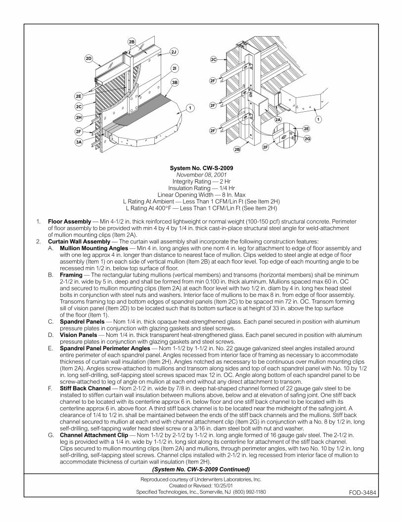
System No. CW-S-2009November 08, 2001
Integrity Rating — 2 HrInsulation Rating — 1/4 Hr
Linear Opening Width — 8 In. MaxL Rating At Ambient — Less Than 1 CFM/Lin Ft (See Item 2H)L Rating At 400°F — Less Than 1 CFM/Lin Ft (See Item 2H)
1. Floor Assembly — Min 4-1/2 in. thick reinforced lightweight or normal weight (100-150 pcf) structural concrete. Perimeter of fl oor assembly to be provided with min 4 by 4 by 1/4 in. thick cast-in-place structural steel angle for weld-attachment of mullion mounting clips (Item 2A).
2. Curtain Wall Assembly — The curtain wall assembly shall incorporate the following construction features:A. Mullion Mounting Angles — Min 4 in. long angles with one nom 4 in. leg for attachment to edge of fl oor assembly and
with one leg approx 4 in. longer than distance to nearest face of mullion. Clips welded to steel angle at edge of fl oor assembly (Item 1) on each side of vertical mullion (Item 2B) at each fl oor level. Top edge of each mounting angle to be recessed min 1/2 in. below top surface of fl oor.
B. Framing — The rectangular tubing mullions (vertical members) and transoms (horizontal members) shall be minimum 2-1/2 in. wide by 5 in. deep and shall be formed from min 0.100 in. thick aluminum. Mullions spaced max 60 in. OC and secured to mullion mounting clips (Item 2A) at each fl oor level with two 1/2 in. diam by 4 in. long hex head steel bolts in conjunction with steel nuts and washers. Interior face of mullions to be max 8 in. from edge of fl oor assembly. Transoms framing top and bottom edges of spandrel panels (Item 2C) to be spaced min 72 in. OC. Transom forming sill of vision panel (Item 2D) to be located such that its bottom surface is at height of 33 in. above the top surface of the fl oor (Item 1).
C. Spandrel Panels — Nom 1/4 in. thick opaque heat-strengthened glass. Each panel secured in position with aluminum pressure plates in conjunction with glazing gaskets and steel screws.
D. Vision Panels — Nom 1/4 in. thick transparent heat-strengthened glass. Each panel secured in position with aluminum pressure plates in conjunction with glazing gaskets and steel screws.
E. Spandrel Panel Perimeter Angles — Nom 1-1/2 by 1-1/2 in. No. 22 gauge galvanized steel angles installed around entire perimeter of each spandrel panel. Angles recessed from interior face of framing as necessary to accommodate thickness of curtain wall insulation (Item 2H). Angles notched as necessary to be continuous over mullion mounting clips (Item 2A). Angles screw-attached to mullions and transom along sides and top of each spandrel panel with No. 10 by 1/2 in. long self-drilling, self-tapping steel screws spaced max 12 in. OC. Angle along bottom of each spandrel panel to be screw-attached to leg of angle on mullion at each end without any direct attachment to transom.
F. Stiff Back Channel — Nom 2-1/2 in. wide by 7/8 in. deep hat-shaped channel formed of 22 gauge galv steel to be installed to stiffen curtain wall insulation between mullions above, below and at elevation of safi ng joint. One stiff back channel to be located with its centerline approx 6 in. below fl oor and one stiff back channel to be located with its centerline approx 6 in. above fl oor. A third stiff back channel is to be located near the midheight of the safi ng joint. A clearance of 1/4 to 1/2 in. shall be maintained between the ends of the stiff back channels and the mullions. Stiff back channel secured to mullion at each end with channel attachment clip (Item 2G) in conjunction with a No. 8 by 1/2 in. long self-drilling, self-tapping wafer head steel screw or a 3/16 in. diam steel bolt with nut and washer.
G. Channel Attachment Clip — Nom 1-1/2 by 2-1/2 by 1-1/2 in. long angle formed of 16 gauge galv steel. The 2-1/2 in. leg is provided with a 1/4 in. wide by 1-1/2 in. long slot along its centerline for attachment of the stiff back channel. Clips secured to mullion mounting clips (Item 2A) and mullions, through perimeter angles, with two No. 10 by 1/2 in. long self-drilling, self-tapping steel screws. Channel clips installed with 2-1/2 in. leg recessed from interior face of mullion to accommodate thickness of curtain wall insulation (Item 2H).
(System No. CW-S-2009 Continued)
Reproduced courtesy of Underwriters Laboratories, Inc.Created or Revised: 10/25/01
Specifi ed Technologies, Inc., Somerville, NJ (800) 992-1180 FOD-3484
H. Curtain Wall Insulation* — Min 2 in. thick mineral wool board insulation, unfaced or faced on one side with aluminum foil/scrim vapor retarder, supplied in min 36 in. wide boards. Insulation boards to be installed with no vertical seams. A full-width board shall be centered at the midheight of fl oor and tightly-fi tted between vertical mullions, fl ush with interior surface of framing. The centered board shall be secured to the stiff back channels (Item 2F) located approx 6 in. above and below the fl oor with cup head weld pins (Item 2J) spaced max 10 in. OC along each channel. The remainder of the spandrel panel framing above and below the centered full-width board shall be fi lled in with additional lengths of board cut to fi t tightly between mullions and with the horizontal seams between board sections tightly butted. The boards shall be secured to the spandrel panel perimeter angles with cup head weld pins at each corner of each board and spaced max 10 in. OC. When faced boards are used, butted seams to be covered with min 4 in. wide aluminum foil tape. When unfaced boards are used, L Ratings do not apply.
ROXUL INC — RHT-80I. Framing Covers — Curtain Wall Insulation* — Min 8 in. wide strips cut from the same min 2 in. thick mineral wool batt
insulation used for the curtain wall insulation (Item 2H). Framing covers to be centered over mullions and secured to the spandrel panel perimeter angles (Item 2E) with cup head weld pins (Item 2J) spaced max 12 in. OC. Where more than one spandrel panel occurs between vertically separated vision panels, the horizontal transom between spandrel panels shall also be covered with an 8 in. wide framing cover in the same manner as on the vertical mullions. Framing covers on mullions to abut the mineral wool batt safi ng material (Item 3A) above and below fl oor.
ROXUL INC — RHT-80J. Weld Pin — No. 12 gauge galv steel weld pin with nom 1-3/16 in. diam galv steel cup head. Cup head weld pins
provided in two lengths. One length to be equal to thickness of curtain wall insulation (Item 2H) and second length to be equal to thickness of curtain wall insulation plus thickness of framing cover (Item 2I). Cup head weld pins inserted through curtain wall insulation and mullion covers and welded to spandrel panel perimeter angles at max OC spacings referenced in Items 2H and 2I.
3. Perimeter Fire Containment System — The perimeter fi re containment system shall incorporated the following construction features:A. Forming Material* — Nom 4 in. thick mineral wool batt safi ng material to be installed in continuous pieces between mullion
clips. Safi ng material to be cut to a min 4-1/2 in. width and stacked to a thickness which is at least 25 percent greater than the width of the linear gap between the curtain wall and the edge of the concrete fl oor slab. The safi ng material is compressed and inserted cut-edge-fi rst into the linear gap such that its top surface is fl ush with the top surface of the fl oor assembly and such that it is friction-fi t between mullion mounting angles. Additional pieces of safi ng material to be friction-fi t into space between mullion mounting clips at each mullion location with top edges of mullion clips covered with a min 1/2 in. thickness of compressed safi ng material.
ROXUL INC — SAFEB. Fill, Void or Cavity Material*— Min 1/8 in. wet thickness (min 1/16 in. dry) of fi ll material spray-applied over top of forming
material and lapping min 1 in. onto the top surface of the concrete fl oor and onto the curtain wall insulation and framing covers. SPECIFIED TECHNOLOGIES INC — SpecSeal AS200 Elastomeric Spray
*Bearing the UL Classifi cation Mark
Reproduced courtesy of Underwriters Laboratories, Inc.Created or Revised: 10/25/01
Specifi ed Technologies, Inc., Somerville, NJ (800) 992-1180 FOD-3484
(System No. CW-S-2009 Continued)

System No. CW-S-2010November 08, 2001
Integrity Rating — 2 HrInsulation Rating — 1/4 Hr
Linear Opening Width — 8 In. MaxL Rating At Ambient — Less Than 1 CFM/Lin Ft (See Item 2H)L Rating At 400°F — Less Than 1 CFM/Lin Ft (See Item 2H)
1. Floor Assembly — Min 4-1/2 in. thick reinforced lightweight or normal weight (100-150 pcf) structural concrete. Perimeter of fl oor assembly to be provided with min 4 by 4 by 1/4 in. thick cast-in-place structural steel angle for weld-attachment of mullion mounting clips (Item 2A).
2. Curtain Wall Assembly — The curtain wall assembly shall incorporate the following construction features:A. Mullion Mounting Angles — Min 4 in. long angles with one nom 4 in. leg for attachment to edge of fl oor assembly and
with one leg approx 4 in. longer than distance to nearest face of mullion. Clips welded to steel angle at edge of fl oor assembly (Item 1) on each side of vertical mullion (Item 2B) at each fl oor level. Top edge of each mounting angle to be recessed min 1/2 in. below top surface of fl oor.
B. Framing — The rectangular tubing mullions (vertical members) and transoms (horizontal members) shall be minimum 2-1/2 in. wide by 5 in. deep and shall be formed from min 0.100 in. thick aluminum. Mullions spaced max 60 in. OC and secured to mullion mounting clips (Item 2A) at each fl oor level with two 1/2 in. diam by 4 in. long hex head steel bolts in conjunction with steel nuts and washers. Interior face of mullions to be max 8 in. from edge of fl oor assembly. Transoms framing top and bottom edges of spandrel panels (Item 2C) to be spaced min 72 in. OC. Transom forming sill of vision panel (Item 2D) to be located such that its bottom surface is at height of 33 in. above the top surface of the fl oor (Item 1).
C. Spandrel Panels — Nom 1/8 in. thick aluminum panels with 1/4 in. thick edges. Each panel secured in position with aluminum pressure plates in conjunction with gaskets and steel screws.
D. Vision Panels — Nom 1/4 in. thick transparent heat-strengthened glass. Each panel secured in position with aluminum pressure plates in conjunction with glazing gaskets and steel screws.
E. Spandrel Panel Perimeter Angles — Nom 1-1/2 by 1-1/2 in. No. 22 gauge galvanized steel angles installed around entire perimeter of each spandrel panel. Angles recessed from interior face of framing as necessary to accommodate thickness of curtain wall insulation (Item 2H). Angles notched as necessary to be continuous over mullion mounting clips (Item 2A). Angles screw-attached to mullions and transom along sides and top of each spandrel panel with No. 10 by 1/2 in. long self-drilling, self-tapping steel screws spaced max 12 in. OC. Angle along bottom of each spandrel panel to be screw-attached to leg of angle on mullion at each end without any direct attachment to transom.
F. Stiff Back Channel — Nom 2-1/2 in. wide by 7/8 in. deep hat-shaped channel formed of 22 gauge galv steel to be installed to stiffen curtain wall insulation between mullions above, below and at elevation of safi ng joint. One stiff back channel to be located with its centerline approx 6 in. below fl oor and one stiff back channel to be located with its centerline approx 6 in. above fl oor. A third stiff back channel is to be located near the midheight of the safi ng joint. A clearance of 1/4 to 1/2 in. shall be maintained between the ends of the stiff back channels and the mullions. Stiff back channel secured to mullion at each end with channel attachment clip (Item 2G) in conjunction with a No. 8 by 1/2 in. long self-drilling, self-tapping wafer head steel screw or a 3/16 in. diam steel bolt with nut and washer.
G. Channel Attachment Clips — Nom 1-1/2 by 2-1/2 by 1-1/2 in. long angle formed of 16 gauge galv steel. The 2-1/2 in. leg is provided with a 1/4 in. wide by 1-1/2 in. long slot along its centerline for attachment of the stiff back channel. Clips secured to mullion mounting clips (Item 2A) and mullions, through perimeter angles, with two No. 10 by 1/2 in. long self-drilling, self-tapping steel screws. Channel clips installed with 2-1/2 in. leg recessed from interior face of mullion to accommodate thickness of curtain wall insulation (Item 2H).
(System No. CW-S-2010 Continued)
Reproduced courtesy of Underwriters Laboratories, Inc.Created or Revised: 10/25/01
Specifi ed Technologies, Inc., Somerville, NJ (800) 992-1180 FOD-3485

H. Curtain Wall Insulation* — Min 2 in. thick mineral wool board insulation, unfaced or faced on one side with aluminum foil/scrim vapor retarder, supplied in min 36 in. wide boards. Insulation boards to be installed with no vertical seams. A full-width board shall be centered at the midheight of fl oor and tightly-fi tted between vertical mullions, fl ush with interior surface of framing. The centered board shall be secured to the stiff back channels (Item 2F) located approx 6 in. above and below the fl oor with cup head weld pins (Item 2J) spaced max 10 in. OC along each channel. The remainder of the spandrel panel framing above and below the centered full-width board shall be fi lled in with additional lengths of board cut to fi t tightly between mullions and with the horizontal seams between board sections tightly butted. The boards shall be secured to the spandrel panel perimeter angles with cup head weld pins at each corner of each board and spaced max 10 in. OC. When faced boards are used, butted seams to be covered with min 4 in. wide aluminum foil tape. When unfaced boards are used, L Ratings do not apply.
ROXUL INC — RHT-80I. Framing Covers — Curtain Wall Insulation* — Min 8 in. wide strips cut from the same min 2 in. thick mineral wool batt
insulation used for the curtain wall insulation (Item 2H). Framing covers to be centered over mullions and secured to the spandrel panel perimeter angles (Item 2E) with cup head weld pins (Item 2J) spaced max 12 in. OC. Where more than one spandrel panel occurs between vertically separated vision panels, the horizontal transom between spandrel panels shall also be covered with an 8 in. wide framing cover in the same manner as on the vertical mullions. Framing covers on mullions to abut the mineral wool batt safi ng material (Item 3A) above and below fl oor.
ROXUL INC — RHT-80 J. Weld Pin — No. 12 gauge galv steel weld pin with nom 1-3/16 in. diam galv steel cup head. Cup head weld pins
provided in two lengths. One length to be equal to thickness of curtain wall insulation (Item 2H) and second length to be equal to thickness of curtain wall insulation plus thickness of framing cover (Item 2I). Cup head weld pins inserted through curtain wall insulation and mullion covers and welded to spandrel panel perimeter angles at max OC spacings referenced in Items 2H and 2I.
3. Perimeter Fire Containment System — The perimeter fi re containment system shall incorporated the following construction features:A. Forming Material* — Nom 4 in. thick mineral wool batt safi ng material to be installed in continuous pieces between mullion
clips. Safi ng material to be cut to a min 4-1/2 in. width and stacked to a thickness which is at least 25 percent greater than the width of the linear gap between the curtain wall and the edge of the concrete fl oor slab. The safi ng material is compressed and inserted cut-edge-fi rst into the linear gap such that its top surface is fl ush with the top surface of the fl oor assembly and such that it is friction-fi t between mullion mounting angles. Additional pieces of safi ng material to be friction-fi t into space between mullion mounting clips at each mullion location with top edges of mullion clips covered with a min 1/2 in. thickness of compressed safi ng material.
ROXUL INC — SAFEB. Fill, Void or Cavity Material* — Min 1/8 in. wet thickness (min 1/16 in. dry) of fi ll material spray-applied over top of forming
material and lapping min 1 in. onto the top surface of the concrete fl oor and onto the curtain wall insulation and framing covers. SPECIFIED TECHNOLOGIES INC — SpecSeal AS200 Elastomeric Spray
*Bearing the UL Classifi cation Mark
Reproduced courtesy of Underwriters Laboratories, Inc.Created or Revised: 10/25/01
Specifi ed Technologies, Inc., Somerville, NJ (800) 992-1180 FOD-3485
(System No. CW-S-2010 Continued)
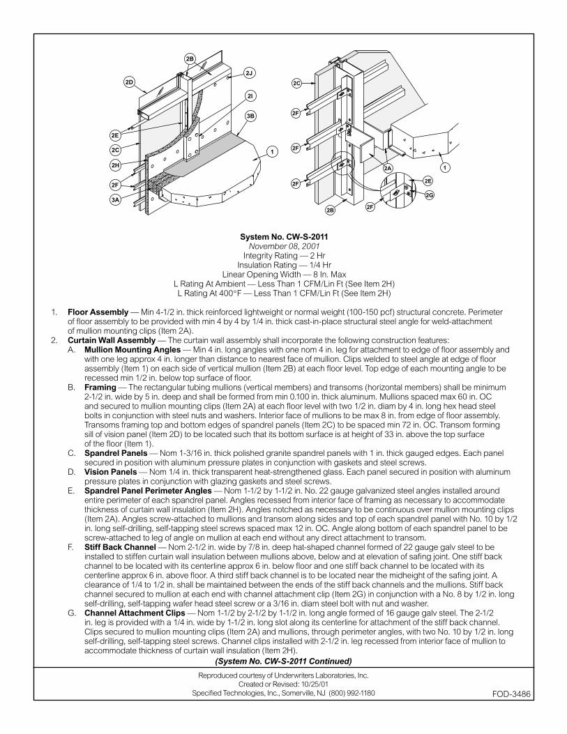
System No. CW-S-2011November 08, 2001
Integrity Rating — 2 HrInsulation Rating — 1/4 Hr
Linear Opening Width — 8 In. MaxL Rating At Ambient — Less Than 1 CFM/Lin Ft (See Item 2H)L Rating At 400°F — Less Than 1 CFM/Lin Ft (See Item 2H)
1. Floor Assembly — Min 4-1/2 in. thick reinforced lightweight or normal weight (100-150 pcf) structural concrete. Perimeter of fl oor assembly to be provided with min 4 by 4 by 1/4 in. thick cast-in-place structural steel angle for weld-attachment of mullion mounting clips (Item 2A).
2. Curtain Wall Assembly — The curtain wall assembly shall incorporate the following construction features:A. Mullion Mounting Angles — Min 4 in. long angles with one nom 4 in. leg for attachment to edge of fl oor assembly and
with one leg approx 4 in. longer than distance to nearest face of mullion. Clips welded to steel angle at edge of fl oor assembly (Item 1) on each side of vertical mullion (Item 2B) at each fl oor level. Top edge of each mounting angle to be recessed min 1/2 in. below top surface of fl oor.
B. Framing — The rectangular tubing mullions (vertical members) and transoms (horizontal members) shall be minimum 2-1/2 in. wide by 5 in. deep and shall be formed from min 0.100 in. thick aluminum. Mullions spaced max 60 in. OC and secured to mullion mounting clips (Item 2A) at each fl oor level with two 1/2 in. diam by 4 in. long hex head steel bolts in conjunction with steel nuts and washers. Interior face of mullions to be max 8 in. from edge of fl oor assembly. Transoms framing top and bottom edges of spandrel panels (Item 2C) to be spaced min 72 in. OC. Transom forming sill of vision panel (Item 2D) to be located such that its bottom surface is at height of 33 in. above the top surface of the fl oor (Item 1).
C. Spandrel Panels — Nom 1-3/16 in. thick polished granite spandrel panels with 1 in. thick gauged edges. Each panel secured in position with aluminum pressure plates in conjunction with gaskets and steel screws.
D. Vision Panels — Nom 1/4 in. thick transparent heat-strengthened glass. Each panel secured in position with aluminum pressure plates in conjunction with glazing gaskets and steel screws.
E. Spandrel Panel Perimeter Angles — Nom 1-1/2 by 1-1/2 in. No. 22 gauge galvanized steel angles installed around entire perimeter of each spandrel panel. Angles recessed from interior face of framing as necessary to accommodate thickness of curtain wall insulation (Item 2H). Angles notched as necessary to be continuous over mullion mounting clips (Item 2A). Angles screw-attached to mullions and transom along sides and top of each spandrel panel with No. 10 by 1/2 in. long self-drilling, self-tapping steel screws spaced max 12 in. OC. Angle along bottom of each spandrel panel to be screw-attached to leg of angle on mullion at each end without any direct attachment to transom.
F. Stiff Back Channel — Nom 2-1/2 in. wide by 7/8 in. deep hat-shaped channel formed of 22 gauge galv steel to be installed to stiffen curtain wall insulation between mullions above, below and at elevation of safi ng joint. One stiff back channel to be located with its centerline approx 6 in. below fl oor and one stiff back channel to be located with its centerline approx 6 in. above fl oor. A third stiff back channel is to be located near the midheight of the safi ng joint. A clearance of 1/4 to 1/2 in. shall be maintained between the ends of the stiff back channels and the mullions. Stiff back channel secured to mullion at each end with channel attachment clip (Item 2G) in conjunction with a No. 8 by 1/2 in. long self-drilling, self-tapping wafer head steel screw or a 3/16 in. diam steel bolt with nut and washer.
G. Channel Attachment Clips — Nom 1-1/2 by 2-1/2 by 1-1/2 in. long angle formed of 16 gauge galv steel. The 2-1/2 in. leg is provided with a 1/4 in. wide by 1-1/2 in. long slot along its centerline for attachment of the stiff back channel. Clips secured to mullion mounting clips (Item 2A) and mullions, through perimeter angles, with two No. 10 by 1/2 in. long self-drilling, self-tapping steel screws. Channel clips installed with 2-1/2 in. leg recessed from interior face of mullion to accommodate thickness of curtain wall insulation (Item 2H).
(System No. CW-S-2011 Continued)
Reproduced courtesy of Underwriters Laboratories, Inc.Created or Revised: 10/25/01
Specifi ed Technologies, Inc., Somerville, NJ (800) 992-1180 FOD-3486
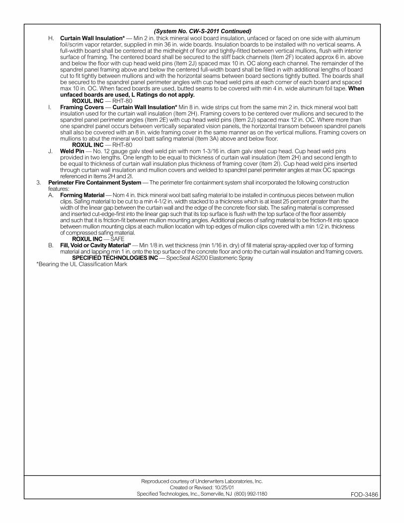
H. Curtain Wall Insulation* — Min 2 in. thick mineral wool board insulation, unfaced or faced on one side with aluminum foil/scrim vapor retarder, supplied in min 36 in. wide boards. Insulation boards to be installed with no vertical seams. A full-width board shall be centered at the midheight of fl oor and tightly-fi tted between vertical mullions, fl ush with interior surface of framing. The centered board shall be secured to the stiff back channels (Item 2F) located approx 6 in. above and below the fl oor with cup head weld pins (Item 2J) spaced max 10 in. OC along each channel. The remainder of the spandrel panel framing above and below the centered full-width board shall be fi lled in with additional lengths of board cut to fi t tightly between mullions and with the horizontal seams between board sections tightly butted. The boards shall be secured to the spandrel panel perimeter angles with cup head weld pins at each corner of each board and spaced max 10 in. OC. When faced boards are used, butted seams to be covered with min 4 in. wide aluminum foil tape. When unfaced boards are used, L Ratings do not apply.
ROXUL INC — RHT-80I. Framing Covers — Curtain Wall Insulation* Min 8 in. wide strips cut from the same min 2 in. thick mineral wool batt
insulation used for the curtain wall insulation (Item 2H). Framing covers to be centered over mullions and secured to the spandrel panel perimeter angles (Item 2E) with cup head weld pins (Item 2J) spaced max 12 in. OC. Where more than one spandrel panel occurs between vertically separated vision panels, the horizontal transom between spandrel panels shall also be covered with an 8 in. wide framing cover in the same manner as on the vertical mullions. Framing covers on mullions to abut the mineral wool batt safi ng material (Item 3A) above and below fl oor.
ROXUL INC — RHT-80 J. Weld Pin — No. 12 gauge galv steel weld pin with nom 1-3/16 in. diam galv steel cup head. Cup head weld pins
provided in two lengths. One length to be equal to thickness of curtain wall insulation (Item 2H) and second length to be equal to thickness of curtain wall insulation plus thickness of framing cover (Item 2I). Cup head weld pins inserted through curtain wall insulation and mullion covers and welded to spandrel panel perimeter angles at max OC spacings referenced in Items 2H and 2I.
3. Perimeter Fire Containment System — The perimeter fi re containment system shall incorporated the following construction features:A. Forming Material — Nom 4 in. thick mineral wool batt safi ng material to be installed in continuous pieces between mullion
clips. Safi ng material to be cut to a min 4-1/2 in. width stacked to a thickness which is at least 25 percent greater than the width of the linear gap between the curtain wall and the edge of the concrete fl oor slab. The safi ng material is compressed and inserted cut-edge-fi rst into the linear gap such that its top surface is fl ush with the top surface of the fl oor assembly and such that it is friction-fi t between mullion mounting angles. Additional pieces of safi ng material to be friction-fi t into space between mullion mounting clips at each mullion location with top edges of mullion clips covered with a min 1/2 in. thickness of compressed safi ng material.
ROXUL INC — SAFEB. Fill, Void or Cavity Material* — Min 1/8 in. wet thickness (min 1/16 in. dry) of fi ll material spray-applied over top of forming
material and lapping min 1 in. onto the top surface of the concrete fl oor and onto the curtain wall insulation and framing covers. SPECIFIED TECHNOLOGIES INC — SpecSeal AS200 Elastomeric Spray
*Bearing the UL Classifi cation Mark
Reproduced courtesy of Underwriters Laboratories, Inc.Created or Revised: 10/25/01
Specifi ed Technologies, Inc., Somerville, NJ (800) 992-1180 FOD-3486
(System No. CW-S-2011 Continued)
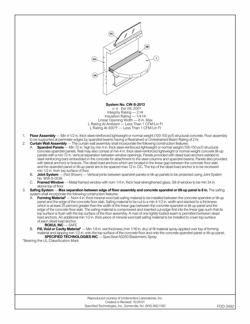
System No. CW-S-2013November 08, 2001
Integrity Rating — 2 HrInsulation Rating — 1/4 Hr
Linear Opening Width — 8 in. MaxL Rating At Ambient — Less Than 1 CFM/Lin FtL Rating At 400°F — Less Than 1 CFM/Lin Ft
1. Floor Assembly — Min 4-1/2 in. thick steel-reinforced lightweight or normal weight (100-150 pcf) structural concrete. Floor assembly to be supported at perimeter edges by spandrel beams having a Restrained or Unrestrained Beam Rating of 2 hr.
2. Curtain Wall Assembly — The curtain wall assembly shall incorporate the following construction features:A. Spandrel Panels — Min 72 in. high by min 4 in. thick steel-reinforced lightweight or normal weight (100-150 pcf) structural
concrete spandrel panels. Wall may also consist of min 4 in. thick steel-reinforced lightweight or normal weight concrete tilt-up panels with a min 72 in. vertical separation between window openings. Panels provided with dead load anchors welded to steel reinforcing bars embedded in the concrete for attachment to the steel columns and spandrel beams. Panels also provided with lateral anchors or braces. The dead load anchors which are located in the linear gap between the concrete fl oor slab and the spandrel panel or tilt-up panel are to be spaced max 72 in. OC. The top of the dead load anchor is to be recessed min 1/2 in. from top surface of fl oor.
B. Joint System — (Not Shown) — Vertical joints between spandrel panels or tilt-up panels to be protected using Joint System No. WW-S-0038.
C. Framed Window — Metal framed window with nom 1/4 in. thick heat-strengthened glass. Sill of window to be min 34 in. above top of fl oor.
3. Safi ng System — Max separation between edge of fl oor assembly and concrete spandrel or tilt-up panel is 8 in. The safi ng system shall incorporate the following construction features:A. Forming Material* — Nom 4 in. thick mineral wool batt safi ng material to be installed between the concrete spandrel or tilt-up
panel and the edge of the concrete fl oor slab. Safi ng material to be cut to a min 4-1/2 in. width and stacked to a thickness which is at least 25 percent greater than the width of the linear gap between the concrete spandrel or tilt-up panel and the edge of the concrete fl oor slab. The safi ng material is compressed and inserted cut-edge-fi rst into the linear gap such that its top surface is fl ush with the top surface of the fl oor assembly. A max of one tightly-butted seam is permitted between dead load anchors. An additional min 1/2 in. thick piece of mineral wool batt safi ng material to be installed to cover top surface of each dead load anchor.
ROXUL INC — SAFEB. Fill, Void or Cavity Material* — Min 1/8 in. wet thickness (min 1/16 in. dry) of fi ll material spray-applied over top of forming
material and lapping min 1/2 in. onto the top surface of the concrete fl oor and onto the concrete spandrel panel or tilt-up panel. SPECIFIED TECHNOLOGIES INC — SpecSeal AS200 Elastomeric Spray
*Bearing the UL Classifi cation Mark
Reproduced courtesy of Underwriters Laboratories, Inc.Created or Revised: 10/25/01
Specifi ed Technologies, Inc., Somerville, NJ (800) 992-1180 FOD-3492
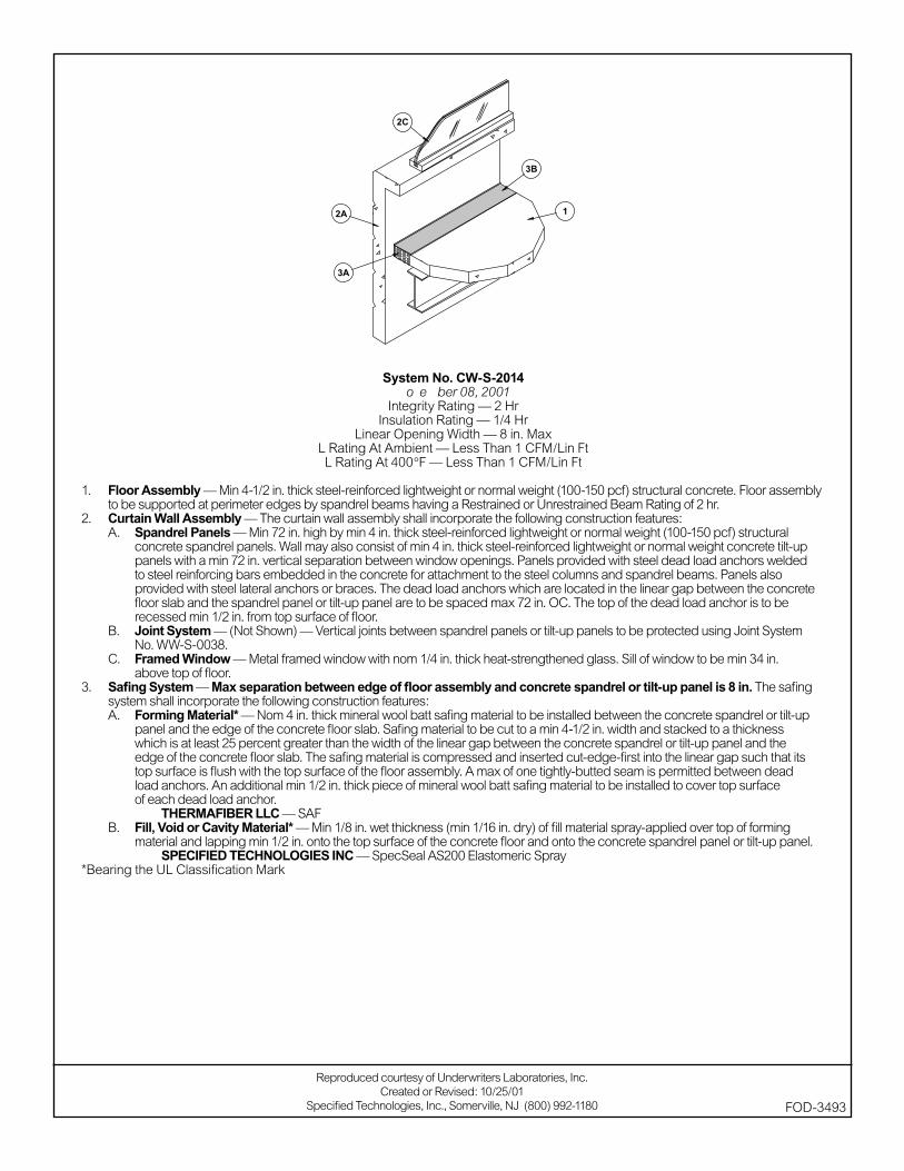
System No. CW-S-2014November 08, 2001
Integrity Rating — 2 HrInsulation Rating — 1/4 Hr
Linear Opening Width — 8 in. MaxL Rating At Ambient — Less Than 1 CFM/Lin FtL Rating At 400°F — Less Than 1 CFM/Lin Ft
1. Floor Assembly — Min 4-1/2 in. thick steel-reinforced lightweight or normal weight (100-150 pcf) structural concrete. Floor assembly to be supported at perimeter edges by spandrel beams having a Restrained or Unrestrained Beam Rating of 2 hr.
2. Curtain Wall Assembly — The curtain wall assembly shall incorporate the following construction features:A. Spandrel Panels — Min 72 in. high by min 4 in. thick steel-reinforced lightweight or normal weight (100-150 pcf) structural
concrete spandrel panels. Wall may also consist of min 4 in. thick steel-reinforced lightweight or normal weight concrete tilt-up panels with a min 72 in. vertical separation between window openings. Panels provided with steel dead load anchors welded to steel reinforcing bars embedded in the concrete for attachment to the steel columns and spandrel beams. Panels also provided with steel lateral anchors or braces. The dead load anchors which are located in the linear gap between the concrete fl oor slab and the spandrel panel or tilt-up panel are to be spaced max 72 in. OC. The top of the dead load anchor is to be recessed min 1/2 in. from top surface of fl oor.
B. Joint System — (Not Shown) — Vertical joints between spandrel panels or tilt-up panels to be protected using Joint System No. WW-S-0038.
C. Framed Window — Metal framed window with nom 1/4 in. thick heat-strengthened glass. Sill of window to be min 34 in. above top of fl oor.
3. Safi ng System — Max separation between edge of fl oor assembly and concrete spandrel or tilt-up panel is 8 in. The safi ng system shall incorporate the following construction features:A. Forming Material* — Nom 4 in. thick mineral wool batt safi ng material to be installed between the concrete spandrel or tilt-up
panel and the edge of the concrete fl oor slab. Safi ng material to be cut to a min 4-1/2 in. width and stacked to a thickness which is at least 25 percent greater than the width of the linear gap between the concrete spandrel or tilt-up panel and the edge of the concrete fl oor slab. The safi ng material is compressed and inserted cut-edge-fi rst into the linear gap such that its top surface is fl ush with the top surface of the fl oor assembly. A max of one tightly-butted seam is permitted between dead load anchors. An additional min 1/2 in. thick piece of mineral wool batt safi ng material to be installed to cover top surface of each dead load anchor.
THERMAFIBER LLC — SAFB. Fill, Void or Cavity Material* — Min 1/8 in. wet thickness (min 1/16 in. dry) of fi ll material spray-applied over top of forming
material and lapping min 1/2 in. onto the top surface of the concrete fl oor and onto the concrete spandrel panel or tilt-up panel. SPECIFIED TECHNOLOGIES INC — SpecSeal AS200 Elastomeric Spray
*Bearing the UL Classifi cation Mark
Reproduced courtesy of Underwriters Laboratories, Inc.Created or Revised: 10/25/01
Specifi ed Technologies, Inc., Somerville, NJ (800) 992-1180 FOD-3493
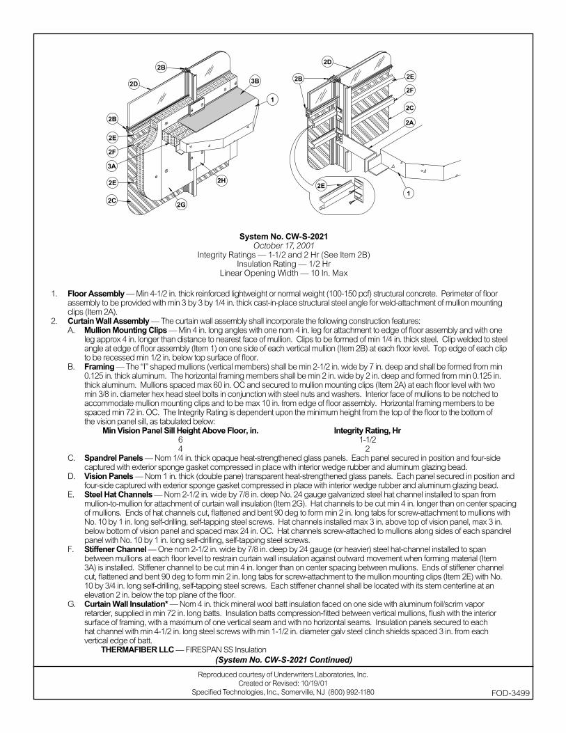
System No. CW-S-2021October 17, 2001
Integrity Ratings — 1-1/2 and 2 Hr (See Item 2B)Insulation Rating — 1/2 Hr
Linear Opening Width — 10 In. Max
1. Floor Assembly — Min 4-1/2 in. thick reinforced lightweight or normal weight (100-150 pcf) structural concrete. Perimeter of fl oor assembly to be provided with min 3 by 3 by 1/4 in. thick cast-in-place structural steel angle for weld-attachment of mullion mounting clips (Item 2A).
2. Curtain Wall Assembly — The curtain wall assembly shall incorporate the following construction features:A. Mullion Mounting Clips — Min 4 in. long angles with one nom 4 in. leg for attachment to edge of fl oor assembly and with one
leg approx 4 in. longer than distance to nearest face of mullion. Clips to be formed of min 1/4 in. thick steel. Clip welded to steel angle at edge of fl oor assembly (Item 1) on one side of each vertical mullion (Item 2B) at each fl oor level. Top edge of each clip to be recessed min 1/2 in. below top surface of fl oor.
B. Framing — The “I” shaped mullions (vertical members) shall be min 2-1/2 in. wide by 7 in. deep and shall be formed from min 0.125 in. thick aluminum. The horizontal framing members shall be min 2 in. wide by 2 in. deep and formed from min 0.125 in. thick aluminum. Mullions spaced max 60 in. OC and secured to mullion mounting clips (Item 2A) at each fl oor level with two min 3/8 in. diameter hex head steel bolts in conjunction with steel nuts and washers. Interior face of mullions to be notched to accommodate mullion mounting clips and to be max 10 in. from edge of fl oor assembly. Horizontal framing members to be spaced min 72 in. OC. The Integrity Rating is dependent upon the minimum height from the top of the fl oor to the bottom of the vision panel sill, as tabulated below:
Min Vision Panel Sill Height Above Floor, in. Integrity Rating, Hr 6 1-1/2 4 2
C. Spandrel Panels — Nom 1/4 in. thick opaque heat-strengthened glass panels. Each panel secured in position and four-side captured with exterior sponge gasket compressed in place with interior wedge rubber and aluminum glazing bead.
D. Vision Panels — Nom 1 in. thick (double pane) transparent heat-strengthened glass panels. Each panel secured in position and four-side captured with exterior sponge gasket compressed in place with interior wedge rubber and aluminum glazing bead.
E. Steel Hat Channels — Nom 2-1/2 in. wide by 7/8 in. deep No. 24 gauge galvanized steel hat channel installed to span from mullion-to-mullion for attachment of curtain wall insulation (Item 2G). Hat channels to be cut min 4 in. longer than on center spacing of mullions. Ends of hat channels cut, fl attened and bent 90 deg to form min 2 in. long tabs for screw-attachment to mullions with No. 10 by 1 in. long self-drilling, self-tapping steel screws. Hat channels installed max 3 in. above top of vision panel, max 3 in. below bottom of vision panel and spaced max 24 in. OC. Hat channels screw-attached to mullions along sides of each spandrel panel with No. 10 by 1 in. long self-drilling, self-tapping steel screws.
F. Stiffener Channel — One nom 2-1/2 in. wide by 7/8 in. deep by 24 gauge (or heavier) steel hat-channel installed to span between mullions at each fl oor level to restrain curtain wall insulation against outward movement when forming material (Item 3A) is installed. Stiffener channel to be cut min 4 in. longer than on center spacing between mullions. Ends of stiffener channel cut, fl attened and bent 90 deg to form min 2 in. long tabs for screw-attachment to the mullion mounting clips (Item 2E) with No. 10 by 3/4 in. long self-drilling, self-tapping steel screws. Each stiffener channel shall be located with its stem centerline at an elevation 2 in. below the top plane of the fl oor.
G. Curtain Wall Insulation* — Nom 4 in. thick mineral wool batt insulation faced on one side with aluminum foil/scrim vapor retarder, supplied in min 72 in. long batts. Insulation batts compression-fi tted between vertical mullions, fl ush with the interior surface of framing, with a maximum of one vertical seam and with no horizontal seams. Insulation panels secured to each hat channel with min 4-1/2 in. long steel screws with min 1-1/2 in. diameter galv steel clinch shields spaced 3 in. from each vertical edge of batt.
THERMAFIBER LLC — FIRESPAN SS Insulation
Reproduced courtesy of Underwriters Laboratories, Inc.Created or Revised: 10/19/01
Specifi ed Technologies, Inc., Somerville, NJ (800) 992-1180 FOD-3499
(System No. CW-S-2021 Continued)
H. Mullion Insulation — Curtain Wall Insulation* — Min 8 in. wide strips cut from min 1 in. thick mineral wool batt insulation. Framing covers to be centered over mullions and secured to the steel hat channels with min 5-1/2 in. long steel screws. Framing covers on mullions to abut the mineral wool batt safi ng material (Item 3A) above and below fl oor.
THERMAFIBER LLC — FIRESPAN Insulation3. Safi ng System — The safi ng system shall incorporate the following construction features:
A. Forming Material* — Nom 4 pcf density mineral wool batt insulation. Batt sections cut to a 4 in. width and stacked to a thickness which is min 20 percent greater than the width of the linear gap between the curtain wall insulation and the edge of the concrete fl oor slab. The forming material is compressed and inserted cut-edge-fi rst into linear gap such that its top surface is fl ush with the top surface of the fl oor assembly. A max of one tightly-butted seam is permitted between mullions. Additional piece of forming material to be friction-fi t into gap between batt sections above mullion mounting clip at each mullion location.
THERMAFIBER LLC — SAFB. Fill, Void or Cavity Material* — Min 1/8 in. wet thickness (min 1/16 in. dry thickness) of fi ll material spray-applied over top of
forming material and lapping min 1/2 in. onto the top surface of the fl oor and onto the curtain wall insulation and mullion covers.SPECIFIED TECHNOLOGIES INC — SpecSeal AS200 Elastomeric Spray
*Bearing the UL Classifi cation Marking
(System No. CW-S-2021 Continued)
FOD-3499
Reproduced courtesy of Underwriters Laboratories, Inc.Created or Revised: 10/19/01
Specifi ed Technologies, Inc., Somerville, NJ (800) 992-1180

System No. CW-S-2021October 17, 2001
Integrity Ratings — 1-1/2 and 2 Hr (See Item 2B)Insulation Rating — 1/2 Hr
Linear Opening Width — 10 In. Max
1. Floor Assembly — Min 4-1/2 in. thick reinforced lightweight or normal weight (100-150 pcf) structural concrete. Perimeter of fl oor assembly to be provided with min 3 by 3 by 1/4 in. thick cast-in-place structural steel angle for weld-attachment of mullion mounting clips (Item 2A).
2. Curtain Wall Assembly — The curtain wall assembly shall incorporate the following construction features:A. Mullion Mounting Clips — Min 4 in. long angles with one nom 4 in. leg for attachment to edge of fl oor assembly and with one
leg approx 4 in. longer than distance to nearest face of mullion. Clips to be formed of min 1/4 in. thick steel. Clip welded to steel angle at edge of fl oor assembly (Item 1) on one side of each vertical mullion (Item 2B) at each fl oor level. Top edge of each clip to be recessed min 1/2 in. below top surface of fl oor.
B. Framing — The “I” shaped mullions (vertical members) shall be min 2-1/2 in. wide by 7 in. deep and shall be formed from min 0.125 in. thick aluminum. The horizontal framing members shall be min 2 in. wide by 2 in. deep and formed from min 0.125 in. thick aluminum. Mullions spaced max 60 in. OC and secured to mullion mounting clips (Item 2A) at each fl oor level with two min 3/8 in. diameter hex head steel bolts in conjunction with steel nuts and washers. Interior face of mullions to be notched to accommodate mullion mounting clips and to be max 10 in. from edge of fl oor assembly. Horizontal framing members to be spaced min 72 in. OC. The Integrity Rating is dependent upon the minimum height from the top of the fl oor to the bottom of the vision panel sill, as tabulated below:
Min Vision Panel Sill Height Above Floor, in. Integrity Rating, Hr 6 1-1/2 4 2
C. Spandrel Panels — Nom 1/4 in. thick opaque heat-strengthened glass panels. Each panel secured in position and four-side captured with exterior sponge gasket compressed in place with interior wedge rubber and aluminum glazing bead.
D. Vision Panels — Nom 1 in. thick (double pane) transparent heat-strengthened glass panels. Each panel secured in position and four-side captured with exterior sponge gasket compressed in place with interior wedge rubber and aluminum glazing bead.
E. Steel Hat Channels — Nom 2-1/2 in. wide by 7/8 in. deep No. 24 gauge galvanized steel hat channel installed to span from mullion-to-mullion for attachment of curtain wall insulation (Item 2G). Hat channels to be cut min 4 in. longer than on center spacing of mullions. Ends of hat channels cut, fl attened and bent 90 deg to form min 2 in. long tabs for screw-attachment to mullions with No. 10 by 1 in. long self-drilling, self-tapping steel screws. Hat channels installed max 3 in. above top of vision panel, max 3 in. below bottom of vision panel and spaced max 24 in. OC. Hat channels screw-attached to mullions along sides of each spandrel panel with No. 10 by 1 in. long self-drilling, self-tapping steel screws.
F. Stiffener Channel — One nom 2-1/2 in. wide by 7/8 in. deep by 24 gauge (or heavier) steel hat-channel installed to span between mullions at each fl oor level to restrain curtain wall insulation against outward movement when forming material (Item 3A) is installed. Stiffener channel to be cut min 4 in. longer than on center spacing between mullions. Ends of stiffener channel cut, fl attened and bent 90 deg to form min 2 in. long tabs for screw-attachment to the mullion mounting clips (Item 2E) with No. 10 by 3/4 in. long self-drilling, self-tapping steel screws. Each stiffener channel shall be located with its stem centerline at an elevation 2 in. below the top plane of the fl oor.
G. Curtain Wall Insulation* — Nom 4 in. thick mineral wool batt insulation faced on one side with aluminum foil/scrim vapor retarder, supplied in min 72 in. long batts. Insulation batts compression-fi tted between vertical mullions, fl ush with the interior surface of framing, with a maximum of one vertical seam and with no horizontal seams. Insulation panels secured to each hat channel with min 4-1/2 in. long steel screws with min 1-1/2 in. diameter galv steel clinch shields spaced 3 in. from each vertical edge of batt.
THERMAFIBER LLC — FIRESPAN SS Insulation
Reproduced courtesy of Underwriters Laboratories, Inc.Created or Revised: 10/19/01
Specifi ed Technologies, Inc., Somerville, NJ (800) 992-1180 FOD-3499
(System No. CW-S-2021 Continued)

H. Mullion Insulation — Curtain Wall Insulation* — Min 8 in. wide strips cut from min 1 in. thick mineral wool batt insulation. Framing covers to be centered over mullions and secured to the steel hat channels with min 5-1/2 in. long steel screws. Framing covers on mullions to abut the mineral wool batt safi ng material (Item 3A) above and below fl oor.
THERMAFIBER LLC — FIRESPAN Insulation3. Safi ng System — The safi ng system shall incorporate the following construction features:
A. Forming Material* — Nom 4 pcf density mineral wool batt insulation. Batt sections cut to a 4 in. width and stacked to a thickness which is min 20 percent greater than the width of the linear gap between the curtain wall insulation and the edge of the concrete fl oor slab. The forming material is compressed and inserted cut-edge-fi rst into linear gap such that its top surface is fl ush with the top surface of the fl oor assembly. A max of one tightly-butted seam is permitted between mullions. Additional piece of forming material to be friction-fi t into gap between batt sections above mullion mounting clip at each mullion location.
THERMAFIBER LLC — SAFB. Fill, Void or Cavity Material* — Min 1/8 in. wet thickness (min 1/16 in. dry thickness) of fi ll material spray-applied over top of
forming material and lapping min 1/2 in. onto the top surface of the fl oor and onto the curtain wall insulation and mullion covers.SPECIFIED TECHNOLOGIES INC — SpecSeal AS200 Elastomeric Spray
*Bearing the UL Classifi cation Marking
(System No. CW-S-2021 Continued)
FOD-3499
Reproduced courtesy of Underwriters Laboratories, Inc.Created or Revised: 10/19/01
Specifi ed Technologies, Inc., Somerville, NJ (800) 992-1180
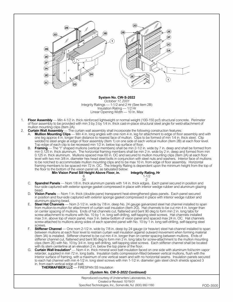
System No. CW-S-2022October 17, 2001
Integrity Ratings — 1-1/2 and 2 Hr (See Item 2B)Insulation Rating — 1/2 Hr
Linear Opening Width — 10 In. Max
1. Floor Assembly — Min 4-1/2 in. thick reinforced lightweight or normal weight (100-150 pcf) structural concrete. Perimeter of fl oor assembly to be provided with min 3 by 3 by 1/4 in. thick cast-in-place structural steel angle for weld-attachment of mullion mounting clips (Item 2A).
2. Curtain Wall Assembly — The curtain wall assembly shall incorporate the following construction features:A. Mullion Mounting Clips — Min 4 in. long angles with one nom 4 in. leg for attachment to edge of fl oor assembly and with
one leg approx 4 in. longer than distance to nearest face of mullion. Clips to be formed of min 1/4 in. thick steel. Clip welded to steel angle at edge of fl oor assembly (Item 1) on one side of each vertical mullion (Item 2B) at each fl oor level. Top edge of each clip to be recessed min 1/2 in. below top surface of fl oor.
B. Framing — The “I” shaped mullions (vertical members) shall be min 2-1/2 in. wide by 7 in. deep and shall be formed from min 0.125 in. thick aluminum. The horizontal framing members shall be min 2 in. wide by 2 in. deep and formed from min 0.125 in. thick aluminum. Mullions spaced max 60 in. OC and secured to mullion mounting clips (Item 2A) at each fl oor level with two min 3/8 in. diameter hex head steel bolts in conjunction with steel nuts and washers. Interior face of mullions to be notched to accommodate mullion mounting clips and to be max 10 in. from edge of fl oor assembly. Horizontal framing members to be spaced min 72 in. OC. The Integrity Rating is dependent upon the minimum height from the top of the fl oor to the bottom of the vision panel sill, as tabulated below:
Min Vision Panel Sill Height Above Floor, in. Integrity Rating, Hr 6 1-1/2 34 2
C. Spandrel Panels — Nom 1/8 in. thick aluminum panels with 1/4 in. thick edges. Each panel secured in position and four-side captured with exterior sponge gasket compressed in place with interior wedge rubber and aluminum glazing bead.
D. Vision Panels — Nom 1 in. thick (double pane) transparent heat-strengthened glass panels. Each panel secured in position and four-side captured with exterior sponge gasket compressed in place with interior wedge rubber and aluminum glazing bead.
E. Steel Hat Channels — Nom 2-1/2 in. wide by 7/8 in. deep No. 24 gauge galvanized steel hat channel installed to span from mullion-to-mullion for attachment of curtain wall insulation (Item 2G). Hat channels to be cut min 4 in. longer than on center spacing of mullions. Ends of hat channels cut, fl attened and bent 90 deg to form min 2 in. long tabs for screw-attachment to mullions with No. 10 by 1 in. long self-drilling, self-tapping steel screws. Hat channels installed max 3 in. above top of vision panel, max 3 in. below bottom of vision panel and spaced max 24 in. OC. Hat channels screw-attached to mullions along sides of each spandrel panel with No. 10 by 1 in. long self-drilling, self-tapping steel screws.
F. Stiffener Channel — One nom 2-1/2 in. wide by 7/8 in. deep by 24 gauge (or heavier) steel hat-channel installed to span between mullions at each fl oor level to restrain curtain wall insulation against outward movement when forming material (Item 3A) is installed. Stiffener channel to be cut min 4 in. longer than on center spacing between mullions. Ends of stiffener channel cut, fl attened and bent 90 deg to form min 2 in. long tabs for screw-attachment to the mullion mounting clips (Item 2E) with No. 10 by 3/4 in. long self-drilling, self-tapping steel screws. Each stiffener channel shall be located with its stem centerline at an elevation 2 in. below the top plane of the fl oor.
G. Curtain Wall Insulation* — Nom 4 in. thick mineral wool batt insulation faced on one side with aluminum foil/scrim vapor retarder, supplied in min 72 in. long batts. Insulation batts compression-fi tted between vertical mullions, fl ush with the interior surface of framing, with a maximum of one vertical seam and with no horizontal seams. Insulation panels secured to each hat channel with min 4-1/2 in. long steel screws with min 1-1/2 in. diameter galv steel clinch shields spaced 3 in. from each vertical edge of batt.
THERMAFIBER LLC — FIRESPAN SS Insulation
Reproduced courtesy of Underwriters Laboratories, Inc.Created or Revised: 10/19/01
Specifi ed Technologies, Inc., Somerville, NJ (800) 992-1180 FOD-3500
(System No. CW-S-2022 Continued)
H. Mullion Insulation — Curtain Wall Insulation* — Min 8 in. wide strips cut from min 1 in. thick mineral wool batt insulation. Framing covers to be centered over mullions and secured to the steel hat channels with min 5-1/2 in. long steel screws. Framing covers on mullions to abut the mineral wool batt safi ng material (Item 3A) above and below fl oor.
THERMAFIBER LLC — FIRESPAN Insulation3. Safi ng System — The safi ng system shall incorporate the following construction features:
A. Forming Material* — Nom 4 pcf density mineral wool batt insulation. Batt sections cut to a 4 in. width and stacked to a thickness which is min 20 percent greater than the width of the linear gap between the curtain wall insulation and the edge of the concrete fl oor slab. The forming material is compressed and inserted cut-edge-fi rst into linear gap such that its top surface is fl ush with the top surface of the fl oor assembly. A max of one tightly-butted seam is permitted between mullions. Additional piece of forming material to be friction-fi t into gap between batt sections above mullion mounting clip at each mullion location.
THERMAFIBER LLC — SAFB. Fill, Void or Cavity Material* — Min 1/8 in. wet thickness (min 1/16 in. dry thickness) of fi ll material spray-applied over top of
forming material and lapping min 1/2 in. onto the top surface of the fl oor and onto the curtain wall insulation and mullion covers.SPECIFIED TECHNOLOGIES INC — SpecSeal AS200 Elastomeric Spray
*Bearing the UL Classifi cation Marking
(System No. CW-S-2022 Continued)
FOD-3500
Reproduced courtesy of Underwriters Laboratories, Inc.Created or Revised: 10/19/01
Specifi ed Technologies, Inc., Somerville, NJ (800) 992-1180
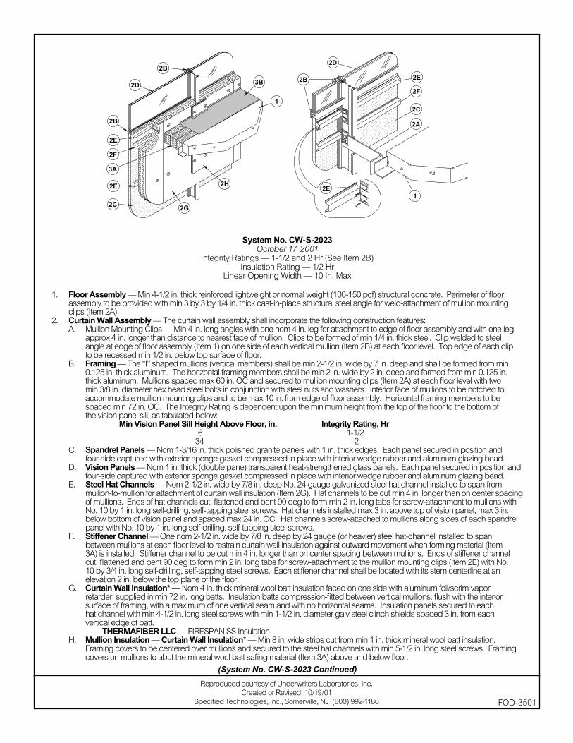
System No. CW-S-2023October 17, 2001
Integrity Ratings — 1-1/2 and 2 Hr (See Item 2B)Insulation Rating — 1/2 Hr
Linear Opening Width — 10 In. Max
1. Floor Assembly — Min 4-1/2 in. thick reinforced lightweight or normal weight (100-150 pcf) structural concrete. Perimeter of fl oor assembly to be provided with min 3 by 3 by 1/4 in. thick cast-in-place structural steel angle for weld-attachment of mullion mounting clips (Item 2A).
2. Curtain Wall Assembly — The curtain wall assembly shall incorporate the following construction features:A. Mullion Mounting Clips — Min 4 in. long angles with one nom 4 in. leg for attachment to edge of fl oor assembly and with one leg
approx 4 in. longer than distance to nearest face of mullion. Clips to be formed of min 1/4 in. thick steel. Clip welded to steel angle at edge of fl oor assembly (Item 1) on one side of each vertical mullion (Item 2B) at each fl oor level. Top edge of each clip to be recessed min 1/2 in. below top surface of fl oor.
B. Framing — The “I” shaped mullions (vertical members) shall be min 2-1/2 in. wide by 7 in. deep and shall be formed from min 0.125 in. thick aluminum. The horizontal framing members shall be min 2 in. wide by 2 in. deep and formed from min 0.125 in. thick aluminum. Mullions spaced max 60 in. OC and secured to mullion mounting clips (Item 2A) at each fl oor level with two min 3/8 in. diameter hex head steel bolts in conjunction with steel nuts and washers. Interior face of mullions to be notched to accommodate mullion mounting clips and to be max 10 in. from edge of fl oor assembly. Horizontal framing members to be spaced min 72 in. OC. The Integrity Rating is dependent upon the minimum height from the top of the fl oor to the bottom of the vision panel sill, as tabulated below:
Min Vision Panel Sill Height Above Floor, in. Integrity Rating, Hr 6 1-1/2 34 2
C. Spandrel Panels — Nom 1-3/16 in. thick polished granite panels with 1 in. thick edges. Each panel secured in position and four-side captured with exterior sponge gasket compressed in place with interior wedge rubber and aluminum glazing bead.
D. Vision Panels — Nom 1 in. thick (double pane) transparent heat-strengthened glass panels. Each panel secured in position and four-side captured with exterior sponge gasket compressed in place with interior wedge rubber and aluminum glazing bead.
E. Steel Hat Channels — Nom 2-1/2 in. wide by 7/8 in. deep No. 24 gauge galvanized steel hat channel installed to span from mullion-to-mullion for attachment of curtain wall insulation (Item 2G). Hat channels to be cut min 4 in. longer than on center spacing of mullions. Ends of hat channels cut, fl attened and bent 90 deg to form min 2 in. long tabs for screw-attachment to mullions with No. 10 by 1 in. long self-drilling, self-tapping steel screws. Hat channels installed max 3 in. above top of vision panel, max 3 in. below bottom of vision panel and spaced max 24 in. OC. Hat channels screw-attached to mullions along sides of each spandrel panel with No. 10 by 1 in. long self-drilling, self-tapping steel screws.
F. Stiffener Channel — One nom 2-1/2 in. wide by 7/8 in. deep by 24 gauge (or heavier) steel hat-channel installed to span between mullions at each fl oor level to restrain curtain wall insulation against outward movement when forming material (Item 3A) is installed. Stiffener channel to be cut min 4 in. longer than on center spacing between mullions. Ends of stiffener channel cut, fl attened and bent 90 deg to form min 2 in. long tabs for screw-attachment to the mullion mounting clips (Item 2E) with No. 10 by 3/4 in. long self-drilling, self-tapping steel screws. Each stiffener channel shall be located with its stem centerline at an elevation 2 in. below the top plane of the fl oor.
G. Curtain Wall Insulation* — Nom 4 in. thick mineral wool batt insulation faced on one side with aluminum foil/scrim vapor retarder, supplied in min 72 in. long batts. Insulation batts compression-fi tted between vertical mullions, fl ush with the interior surface of framing, with a maximum of one vertical seam and with no horizontal seams. Insulation panels secured to each hat channel with min 4-1/2 in. long steel screws with min 1-1/2 in. diameter galv steel clinch shields spaced 3 in. from each vertical edge of batt.
THERMAFIBER LLC — FIRESPAN SS InsulationH. Mullion Insulation — Curtain Wall Insulation* — Min 8 in. wide strips cut from min 1 in. thick mineral wool batt insulation.
Framing covers to be centered over mullions and secured to the steel hat channels with min 5-1/2 in. long steel screws. Framing covers on mullions to abut the mineral wool batt safi ng material (Item 3A) above and below fl oor.
Reproduced courtesy of Underwriters Laboratories, Inc.Created or Revised: 10/19/01
Specifi ed Technologies, Inc., Somerville, NJ (800) 992-1180 FOD-3501
(System No. CW-S-2023 Continued)
THERMAFIBER LLC — FIRESPAN Insulation3. Safi ng System — The safi ng system shall incorporate the following construction features:
A. Forming Material* — Nom 4 pcf density mineral wool batt insulation. Batt sections cut to a 4 in. width and stacked to a thickness which is min 20 percent greater than the width of the linear gap between the curtain wall insulation and the edge of the concrete fl oor slab. The forming material is compressed and inserted cut-edge-fi rst into linear gap such that its top surface is fl ush with the top surface of the fl oor assembly. A max of one tightly-butted seam is permitted between mullions. Additional piece of forming material to be friction-fi t into gap between batt sections above mullion mounting clip at each mullion location.
THERMAFIBER LLC — SAFB. Fill, Void or Cavity Material* — Min 1/8 in. wet thickness (min 1/16 in. dry thickness) of fi ll material spray-applied over top of
forming material and lapping min 1/2 in. onto the top surface of the fl oor and onto the curtain wall insulation and mullion covers.SPECIFIED TECHNOLOGIES INC — SpecSeal AS200 Elastomeric Spray
*Bearing the UL Classifi cation Marking
(System No. CW-S-2023 Continued)
FOD-3501
Reproduced courtesy of Underwriters Laboratories, Inc.Created or Revised: 10/19/01
Specifi ed Technologies, Inc., Somerville, NJ (800) 992-1180
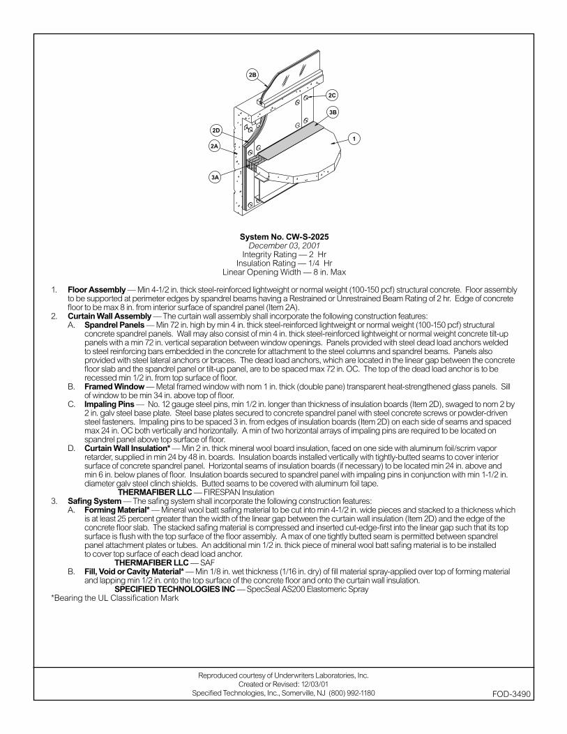
System No. CW-S-2025December 03, 2001
Integrity Rating — 2 HrInsulation Rating — 1/4 Hr
Linear Opening Width — 8 in. Max
1. Floor Assembly — Min 4-1/2 in. thick steel-reinforced lightweight or normal weight (100-150 pcf) structural concrete. Floor assembly to be supported at perimeter edges by spandrel beams having a Restrained or Unrestrained Beam Rating of 2 hr. Edge of concrete fl oor to be max 8 in. from interior surface of spandrel panel (Item 2A).
2. Curtain Wall Assembly — The curtain wall assembly shall incorporate the following construction features:A. Spandrel Panels — Min 72 in. high by min 4 in. thick steel-reinforced lightweight or normal weight (100-150 pcf) structural
concrete spandrel panels. Wall may also consist of min 4 in. thick steel-reinforced lightweight or normal weight concrete tilt-up panels with a min 72 in. vertical separation between window openings. Panels provided with steel dead load anchors welded to steel reinforcing bars embedded in the concrete for attachment to the steel columns and spandrel beams. Panels also provided with steel lateral anchors or braces. The dead load anchors, which are located in the linear gap between the concrete fl oor slab and the spandrel panel or tilt-up panel, are to be spaced max 72 in. OC. The top of the dead load anchor is to be recessed min 1/2 in. from top surface of fl oor.
B. Framed Window — Metal framed window with nom 1 in. thick (double pane) transparent heat-strengthened glass panels. Sill of window to be min 34 in. above top of fl oor.
C. Impaling Pins — No. 12 gauge steel pins, min 1/2 in. longer than thickness of insulation boards (Item 2D), swaged to nom 2 by 2 in. galv steel base plate. Steel base plates secured to concrete spandrel panel with steel concrete screws or powder-driven steel fasteners. Impaling pins to be spaced 3 in. from edges of insulation boards (Item 2D) on each side of seams and spaced max 24 in. OC both vertically and horizontally. A min of two horizontal arrays of impaling pins are required to be located on spandrel panel above top surface of fl oor.
D. Curtain Wall Insulation* — Min 2 in. thick mineral wool board insulation, faced on one side with aluminum foil/scrim vapor retarder, supplied in min 24 by 48 in. boards. Insulation boards installed vertically with tightly-butted seams to cover interior surface of concrete spandrel panel. Horizontal seams of insulation boards (if necessary) to be located min 24 in. above and min 6 in. below planes of fl oor. Insulation boards secured to spandrel panel with impaling pins in conjunction with min 1-1/2 in. diameter galv steel clinch shields. Butted seams to be covered with aluminum foil tape.
THERMAFIBER LLC — FIRESPAN Insulation3. Safi ng System — The safi ng system shall incorporate the following construction features:
A. Forming Material* — Mineral wool batt safi ng material to be cut into min 4-1/2 in. wide pieces and stacked to a thickness which is at least 25 percent greater than the width of the linear gap between the curtain wall insulation (Item 2D) and the edge of the concrete fl oor slab. The stacked safi ng material is compressed and inserted cut-edge-fi rst into the linear gap such that its top surface is fl ush with the top surface of the fl oor assembly. A max of one tightly butted seam is permitted between spandrel panel attachment plates or tubes. An additional min 1/2 in. thick piece of mineral wool batt safi ng material is to be installed to cover top surface of each dead load anchor.
THERMAFIBER LLC — SAFB. Fill, Void or Cavity Material* — Min 1/8 in. wet thickness (1/16 in. dry) of fi ll material spray-applied over top of forming material
and lapping min 1/2 in. onto the top surface of the concrete fl oor and onto the curtain wall insulation. SPECIFIED TECHNOLOGIES INC — SpecSeal AS200 Elastomeric Spray
*Bearing the UL Classifi cation Mark
Reproduced courtesy of Underwriters Laboratories, Inc.Created or Revised: 12/03/01
Specifi ed Technologies, Inc., Somerville, NJ (800) 992-1180 FOD-3490
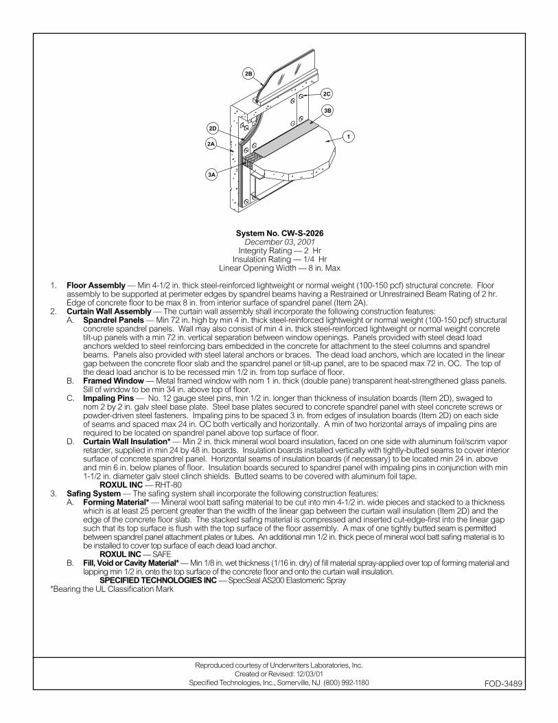
System No. CW-S-2026December 03, 2001
Integrity Rating — 2 HrInsulation Rating — 1/4 Hr
Linear Opening Width — 8 in. Max
1. Floor Assembly — Min 4-1/2 in. thick steel-reinforced lightweight or normal weight (100-150 pcf) structural concrete. Floor assembly to be supported at perimeter edges by spandrel beams having a Restrained or Unrestrained Beam Rating of 2 hr. Edge of concrete fl oor to be max 8 in. from interior surface of spandrel panel (Item 2A).
2. Curtain Wall Assembly — The curtain wall assembly shall incorporate the following construction features:A. Spandrel Panels — Min 72 in. high by min 4 in. thick steel-reinforced lightweight or normal weight (100-150 pcf) structural
concrete spandrel panels. Wall may also consist of min 4 in. thick steel-reinforced lightweight or normal weight concrete tilt-up panels with a min 72 in. vertical separation between window openings. Panels provided with steel dead load anchors welded to steel reinforcing bars embedded in the concrete for attachment to the steel columns and spandrel beams. Panels also provided with steel lateral anchors or braces. The dead load anchors, which are located in the linear gap between the concrete fl oor slab and the spandrel panel or tilt-up panel, are to be spaced max 72 in. OC. The top of the dead load anchor is to be recessed min 1/2 in. from top surface of fl oor.
B. Framed Window — Metal framed window with nom 1 in. thick (double pane) transparent heat-strengthened glass panels. Sill of window to be min 34 in. above top of fl oor.
C. Impaling Pins — No. 12 gauge steel pins, min 1/2 in. longer than thickness of insulation boards (Item 2D), swaged to nom 2 by 2 in. galv steel base plate. Steel base plates secured to concrete spandrel panel with steel concrete screws or powder-driven steel fasteners. Impaling pins to be spaced 3 in. from edges of insulation boards (Item 2D) on each side of seams and spaced max 24 in. OC both vertically and horizontally. A min of two horizontal arrays of impaling pins are required to be located on spandrel panel above top surface of fl oor.
D. Curtain Wall Insulation* — Min 2 in. thick mineral wool board insulation, faced on one side with aluminum foil/scrim vapor retarder, supplied in min 24 by 48 in. boards. Insulation boards installed vertically with tightly-butted seams to cover interior surface of concrete spandrel panel. Horizontal seams of insulation boards (if necessary) to be located min 24 in. above and min 6 in. below planes of fl oor. Insulation boards secured to spandrel panel with impaling pins in conjunction with min 1-1/2 in. diameter galv steel clinch shields. Butted seams to be covered with aluminum foil tape.
ROXUL INC — RHT-803. Safi ng System — The safi ng system shall incorporate the following construction features:
A. Forming Material* — Mineral wool batt safi ng material to be cut into min 4-1/2 in. wide pieces and stacked to a thickness which is at least 25 percent greater than the width of the linear gap between the curtain wall insulation (Item 2D) and the edge of the concrete fl oor slab. The stacked safi ng material is compressed and inserted cut-edge-fi rst into the linear gap such that its top surface is fl ush with the top surface of the fl oor assembly. A max of one tightly butted seam is permitted between spandrel panel attachment plates or tubes. An additional min 1/2 in. thick piece of mineral wool batt safi ng material is to be installed to cover top surface of each dead load anchor.
ROXUL INC — SAFEB. Fill, Void or Cavity Material* — Min 1/8 in. wet thickness (1/16 in. dry) of fi ll material spray-applied over top of forming material and
lapping min 1/2 in. onto the top surface of the concrete fl oor and onto the curtain wall insulation.SPECIFIED TECHNOLOGIES INC — SpecSeal AS200 Elastomeric Spray
*Bearing the UL Classifi cation Mark
Reproduced courtesy of Underwriters Laboratories, Inc.Created or Revised: 12/03/01
Specifi ed Technologies, Inc., Somerville, NJ (800) 992-1180 FOD-3489
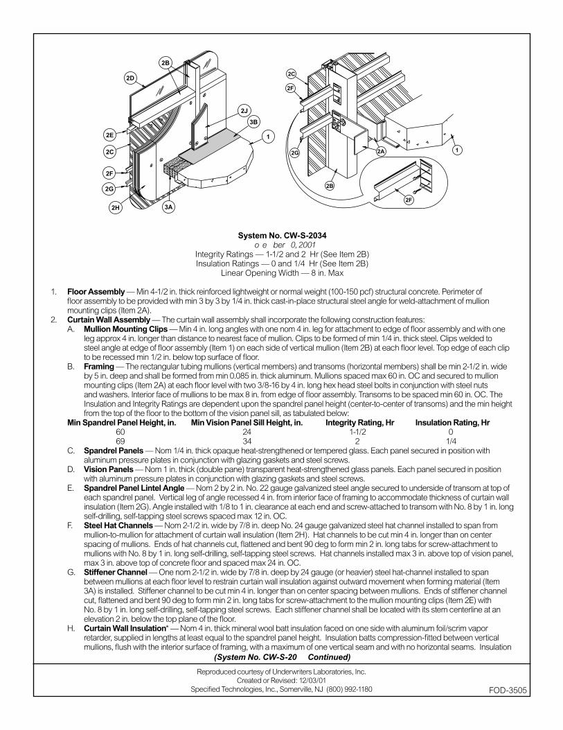
System No. CW-S-2034November 30, 2001
Integrity Ratings — 1-1/2 and 2 Hr (See Item 2B)Insulation Ratings — 0 and 1/4 Hr (See Item 2B)
Linear Opening Width — 8 in. Max
1. Floor Assembly — Min 4-1/2 in. thick reinforced lightweight or normal weight (100-150 pcf) structural concrete. Perimeter of fl oor assembly to be provided with min 3 by 3 by 1/4 in. thick cast-in-place structural steel angle for weld-attachment of mullion mounting clips (Item 2A).
2. Curtain Wall Assembly — The curtain wall assembly shall incorporate the following construction features:A. Mullion Mounting Clips — Min 4 in. long angles with one nom 4 in. leg for attachment to edge of fl oor assembly and with one
leg approx 4 in. longer than distance to nearest face of mullion. Clips to be formed of min 1/4 in. thick steel. Clips welded to steel angle at edge of fl oor assembly (Item 1) on each side of vertical mullion (Item 2B) at each fl oor level. Top edge of each clip to be recessed min 1/2 in. below top surface of fl oor.
B. Framing — The rectangular tubing mullions (vertical members) and transoms (horizontal members) shall be min 2-1/2 in. wide by 5 in. deep and shall be formed from min 0.085 in. thick aluminum. Mullions spaced max 60 in. OC and secured to mullion mounting clips (Item 2A) at each fl oor level with two 3/8-16 by 4 in. long hex head steel bolts in conjunction with steel nuts and washers. Interior face of mullions to be max 8 in. from edge of fl oor assembly. Transoms to be spaced min 60 in. OC. The Insulation and Integrity Ratings are dependent upon the spandrel panel height (center-to-center of transoms) and the min height from the top of the fl oor to the bottom of the vision panel sill, as tabulated below:
Min Spandrel Panel Height, in. Min Vision Panel Sill Height, in. Integrity Rating, Hr Insulation Rating, Hr 60 24 1-1/2 0 69 34 2 1/4C. Spandrel Panels — Nom 1/4 in. thick opaque heat-strengthened or tempered glass. Each panel secured in position with
aluminum pressure plates in conjunction with glazing gaskets and steel screws.D. Vision Panels — Nom 1 in. thick (double pane) transparent heat-strengthened glass panels. Each panel secured in position
with aluminum pressure plates in conjunction with glazing gaskets and steel screws.E. Spandrel Panel Lintel Angle — Nom 2 by 2 in. No. 22 gauge galvanized steel angle secured to underside of transom at top of
each spandrel panel. Vertical leg of angle recessed 4 in. from interior face of framing to accommodate thickness of curtain wall insulation (Item 2G). Angle installed with 1/8 to 1 in. clearance at each end and screw-attached to transom with No. 8 by 1 in. long self-drilling, self-tapping steel screws spaced max 12 in. OC.
F. Steel Hat Channels — Nom 2-1/2 in. wide by 7/8 in. deep No. 24 gauge galvanized steel hat channel installed to span from mullion-to-mullion for attachment of curtain wall insulation (Item 2H). Hat channels to be cut min 4 in. longer than on center spacing of mullions. Ends of hat channels cut, fl attened and bent 90 deg to form min 2 in. long tabs for screw-attachment to mullions with No. 8 by 1 in. long self-drilling, self-tapping steel screws. Hat channels installed max 3 in. above top of vision panel, max 3 in. above top of concrete fl oor and spaced max 24 in. OC.
G. Stiffener Channel — One nom 2-1/2 in. wide by 7/8 in. deep by 24 gauge (or heavier) steel hat-channel installed to span between mullions at each fl oor level to restrain curtain wall insulation against outward movement when forming material (Item 3A) is installed. Stiffener channel to be cut min 4 in. longer than on center spacing between mullions. Ends of stiffener channel cut, fl attened and bent 90 deg to form min 2 in. long tabs for screw-attachment to the mullion mounting clips (Item 2E) with No. 8 by 1 in. long self-drilling, self-tapping steel screws. Each stiffener channel shall be located with its stem centerline at an elevation 2 in. below the top plane of the fl oor.
H. Curtain Wall Insulation* — Nom 4 in. thick mineral wool batt insulation faced on one side with aluminum foil/scrim vapor retarder, supplied in lengths at least equal to the spandrel panel height. Insulation batts compression-fi tted between vertical mullions, fl ush with the interior surface of framing, with a maximum of one vertical seam and with no horizontal seams. Insulation
Reproduced courtesy of Underwriters Laboratories, Inc.Created or Revised: 12/03/01
Specifi ed Technologies, Inc., Somerville, NJ (800) 992-1180 FOD-3505
(System No. CW-S-2034 Continued)
panels secured to the spandrel panel lintel angle and to each hat channel with min 4-1/2 in. long steel screws with min 1-1/2 in. diameter galv steel clinch shields spaced 3 in. from each vertical edge of batt and spaced max 24 in. OC between vertical edges of batt.
THERMAFIBER LLC — FIRESPAN SS InsulationJ. Framing Covers — Curtain Wall Insulation* Min 8 in. wide strips cut from min 2 in. thick mineral wool batt insulation. Framing
covers to be centered over mullions and secured to the spandrel panel lintel angle and steel hat channels with min 6-1/2 in. long steel screws. Framing covers on mullions to abut the mineral wool batt safi ng material (Item 3A) above and below fl oor. Where more than one spandrel panel occurs between vertically separated vision panels, the horizontal transom between spandrel panels shall also be covered with an 8 in. wide framing cover in the same manner as on the vertical mullions.
THERMAFIBER LLC — FIRESPAN Insulation3. Safi ng System — The safi ng system shall incorporate the following construction features:
A. Forming Material* — Nom 4 pcf density mineral wool batt insulation. Batt sections cut to a min 4-1/2 in. width and stacked to a thickness which is min 20 percent greater than the width of linear gap between the curtain wall insulation and the edge of the concrete fl oor slab. The forming material is compressed and inserted cut-edge-fi rst into linear gap such that its top surface is fl ush with the top surface of the fl oor assembly. A max of one tightly-butted seam is permitted between mullions. Additional pieces of forming material to be friction-fi t into spaces between mullion mounting clips at each mullion location.
THERMAFIBER LLC — SAFB. Fill, Void or Cavity Material* — Min 1/8 in. wet thickness (min 1/16 in. dry thickness) of fi ll material spray-applied over
top of forming material and lapping min 1/2 in. onto the top surface of the fl oor and onto the curtain wall insulation and framing covers.
SPECIFIED TECHNOLOGIES INC — SpecSeal AS200 Elastomeric Spray*Bearing the UL Classifi cation Marking
(System No. CW-S-2034 Continued)
FOD-3505
Reproduced courtesy of Underwriters Laboratories, Inc.Created or Revised: 12/03/01
Specifi ed Technologies, Inc., Somerville, NJ (800) 992-1180

System No. CW-S-2035November 30, 2001
Integrity Ratings — 1-1/2 and 2 Hr (See Item 2B)Insulation Ratings — 0 and 1/4 Hr (See Item 2B)
Linear Opening Width — 8 in. Max
1. Floor Assembly — Min 4-1/2 in. thick reinforced lightweight or normal weight (100-150 pcf) structural concrete. Perimeter of fl oor assembly to be provided with min 3 by 3 by 1/4 in. thick cast-in-place structural steel angle for weld-attachment of mullion mounting clips (Item 2A).
2. Curtain Wall Assembly — The curtain wall assembly shall incorporate the following construction features:A. Mullion Mounting Clips — Min 4 in. long angles with one nom 4 in. leg for attachment to edge of fl oor assembly and with one
leg approx 4 in. longer than distance to nearest face of mullion. Clips to be formed of min 1/4 in. thick steel. Clips welded to steel angle at edge of fl oor assembly (Item 1) on each side of vertical mullion (Item 2B) at each fl oor level. Top edge of each clip to be recessed min 1/2 in. below top surface of fl oor.
B. Framing — The rectangular tubing mullions (vertical members) and transoms (horizontal members) shall be min 2-1/2 in. wide by 5 in. deep and shall be formed from min 0.085 in. thick aluminum. Mullions spaced max 60 in. OC and secured to mullion mounting clips (Item 2A) at each fl oor level with two 3/8-16 by 4 in. long hex head steel bolts in conjunction with steel nuts and washers. Interior face of mullions to be max 8 in. from edge of fl oor assembly. Transoms to be spaced min 60 in. OC. The Insulation and Integrity Ratings are dependent upon the spandrel panel height (center-to-center of transoms) and the min height from the top of the fl oor to the bottom of the vision panel sill, as tabulated below:
Min Spandrel Panel Height, in. Min Vision Panel Sill Height, in. Integrity Rating, Hr Insulation Rating, Hr 60 24 1-1/2 0 69 34 2 1/4C. Spandrel Panels — Nom 1/8 in. thick aluminum panels with 1/4 in. thick edges. Each panel secured in position with aluminum
pressure plates in conjunction with glazing gaskets and steel screws.D. Vision Panels — Nom 1 in. thick (double pane) transparent heat-strengthened glass panels. Each panel secured in position
with aluminum pressure plates in conjunction with glazing gaskets and steel screws.E. Spandrel Panel Lintel Angle — Nom 2 by 2 in. No. 22 gauge galvanized steel angle secured to underside of transom at top of
each spandrel panel. Vertical leg of angle recessed 4 in. from interior face of framing to accommodate thickness of curtain wall insulation (Item 2G). Angle installed with 1/8 to 1 in. clearance at each end and screw-attached to transom with No. 8 by 1 in. long self-drilling, self-tapping steel screws spaced max 12 in. OC.
F. Steel Hat Channels — Nom 2-1/2 in. wide by 7/8 in. deep No. 24 gauge galvanized steel hat channel installed to span from mullion-to-mullion for attachment of curtain wall insulation (Item 2H). Hat channels to be cut min 4 in. longer than on center spacing of mullions. Ends of hat channels cut, fl attened and bent 90 deg to form min 2 in. long tabs for screw-attachment to mullions with No. 8 by 1 in. long self-drilling, self-tapping steel screws. Hat channels installed max 3 in. above top of vision panel, max 3 in. above top of concrete fl oor and spaced max 24 in. OC.
G. Stiffener Channel — One nom 2-1/2 in. wide by 7/8 in. deep by 24 gauge (or heavier) steel hat-channel installed to span between mullions at each fl oor level to restrain curtain wall insulation against outward movement when forming material (Item 3A) is installed. Stiffener channel to be cut min 4 in. longer than on center spacing between mullions. Ends of stiffener channel cut, fl attened and bent 90 deg to form min 2 in. long tabs for screw-attachment to the mullion mounting clips (Item 2E) with No. 8 by 1 in. long self-drilling, self-tapping steel screws. Each stiffener channel shall be located with its stem centerline at an elevation 2 in. below the top plane of the fl oor.
H. Curtain Wall Insulation* — Nom 4 in. thick mineral wool batt insulation faced on one side with aluminum foil/scrim vapor retarder, supplied in lengths at least equal to the spandrel panel height. Insulation batts compression-fi tted between vertical mullions, fl ush with the interior surface of framing, with a maximum of one vertical seam and with no horizontal seams. Insulation
Reproduced courtesy of Underwriters Laboratories, Inc.Created or Revised: 12/03/01
Specifi ed Technologies, Inc., Somerville, NJ (800) 992-1180 FOD-3506
(System No. CW-S-2035 Continued)

panels secured to the spandrel panel lintel angle and to each hat channel with min 4-1/2 in. long steel screws with min 1-1/2 in. diameter galv steel clinch shields spaced 3 in. from each vertical edge of batt and spaced max 24 in. OC between vertical edges of batt.
THERMAFIBER LLC — FIRESPAN SS InsulationJ. Framing Covers — Curtain Wall Insulation* Min 8 in. wide strips cut from min 2 in. thick mineral wool batt insulation. Framing
covers to be centered over mullions and secured to the spandrel panel lintel angle and steel hat channels with min 6-1/2 in. long steel screws. Framing covers on mullions to abut the mineral wool batt safi ng material (Item 3A) above and below fl oor. Where more than one spandrel panel occurs between vertically separated vision panels, the horizontal transom between spandrel panels shall also be covered with an 8 in. wide framing cover in the same manner as on the vertical mullions.
THERMAFIBER LLC — FIRESPAN Insulation3. Safi ng System — The safi ng system shall incorporate the following construction features:
A. Forming Material* — Nom 4 pcf density mineral wool batt insulation. Batt sections cut to a min 4-1/2 in. width and stacked to a thickness which is min 20 percent greater than the width of linear gap between the curtain wall insulation and the edge of the concrete fl oor slab. The forming material is compressed and inserted cut-edge-fi rst into linear gap such that its top surface is fl ush with the top surface of the fl oor assembly. A max of one tightly-butted seam is permitted between mullions. Additional pieces of forming material to be friction-fi t into spaces between mullion mounting clips at each mullion location.
THERMAFIBER LLC — SAFB. Fill, Void or Cavity Material* — Min 1/8 in. wet thickness (min 1/16 in. dry thickness) of fi ll material spray-applied over
top of forming material and lapping min 1/2 in. onto the top surface of the fl oor and onto the curtain wall insulation and framing covers.
SPECIFIED TECHNOLOGIES INC — SpecSeal AS200 Elastomeric Spray*Bearing the UL Classifi cation Marking
(System No. CW-S-2035 Continued)
FOD-3506
Reproduced courtesy of Underwriters Laboratories, Inc.Created or Revised: 12/03/01
Specifi ed Technologies, Inc., Somerville, NJ (800) 992-1180
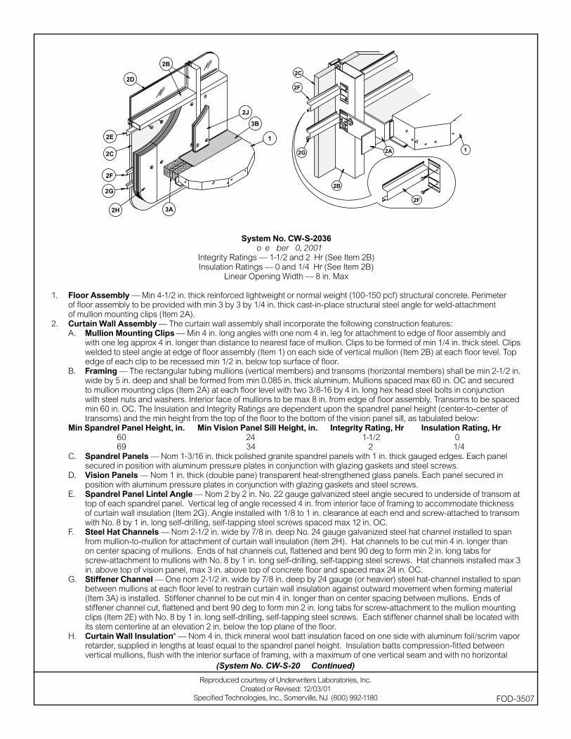
System No. CW-S-2036November 30, 2001
Integrity Ratings — 1-1/2 and 2 Hr (See Item 2B)Insulation Ratings — 0 and 1/4 Hr (See Item 2B)
Linear Opening Width — 8 in. Max
1. Floor Assembly — Min 4-1/2 in. thick reinforced lightweight or normal weight (100-150 pcf) structural concrete. Perimeter of fl oor assembly to be provided with min 3 by 3 by 1/4 in. thick cast-in-place structural steel angle for weld-attachment of mullion mounting clips (Item 2A).
2. Curtain Wall Assembly — The curtain wall assembly shall incorporate the following construction features:A. Mullion Mounting Clips — Min 4 in. long angles with one nom 4 in. leg for attachment to edge of fl oor assembly and
with one leg approx 4 in. longer than distance to nearest face of mullion. Clips to be formed of min 1/4 in. thick steel. Clips welded to steel angle at edge of fl oor assembly (Item 1) on each side of vertical mullion (Item 2B) at each fl oor level. Top edge of each clip to be recessed min 1/2 in. below top surface of fl oor.
B. Framing — The rectangular tubing mullions (vertical members) and transoms (horizontal members) shall be min 2-1/2 in. wide by 5 in. deep and shall be formed from min 0.085 in. thick aluminum. Mullions spaced max 60 in. OC and secured to mullion mounting clips (Item 2A) at each fl oor level with two 3/8-16 by 4 in. long hex head steel bolts in conjunction with steel nuts and washers. Interior face of mullions to be max 8 in. from edge of fl oor assembly. Transoms to be spaced min 60 in. OC. The Insulation and Integrity Ratings are dependent upon the spandrel panel height (center-to-center of transoms) and the min height from the top of the fl oor to the bottom of the vision panel sill, as tabulated below:
Min Spandrel Panel Height, in. Min Vision Panel Sill Height, in. Integrity Rating, Hr Insulation Rating, Hr 60 24 1-1/2 0 69 34 2 1/4C. Spandrel Panels — Nom 1-3/16 in. thick polished granite spandrel panels with 1 in. thick gauged edges. Each panel
secured in position with aluminum pressure plates in conjunction with glazing gaskets and steel screws.D. Vision Panels — Nom 1 in. thick (double pane) transparent heat-strengthened glass panels. Each panel secured in
position with aluminum pressure plates in conjunction with glazing gaskets and steel screws.E. Spandrel Panel Lintel Angle — Nom 2 by 2 in. No. 22 gauge galvanized steel angle secured to underside of transom at
top of each spandrel panel. Vertical leg of angle recessed 4 in. from interior face of framing to accommodate thickness of curtain wall insulation (Item 2G). Angle installed with 1/8 to 1 in. clearance at each end and screw-attached to transom with No. 8 by 1 in. long self-drilling, self-tapping steel screws spaced max 12 in. OC.
F. Steel Hat Channels — Nom 2-1/2 in. wide by 7/8 in. deep No. 24 gauge galvanized steel hat channel installed to span from mullion-to-mullion for attachment of curtain wall insulation (Item 2H). Hat channels to be cut min 4 in. longer than on center spacing of mullions. Ends of hat channels cut, fl attened and bent 90 deg to form min 2 in. long tabs for screw-attachment to mullions with No. 8 by 1 in. long self-drilling, self-tapping steel screws. Hat channels installed max 3 in. above top of vision panel, max 3 in. above top of concrete fl oor and spaced max 24 in. OC.
G. Stiffener Channel — One nom 2-1/2 in. wide by 7/8 in. deep by 24 gauge (or heavier) steel hat-channel installed to span between mullions at each fl oor level to restrain curtain wall insulation against outward movement when forming material (Item 3A) is installed. Stiffener channel to be cut min 4 in. longer than on center spacing between mullions. Ends of stiffener channel cut, fl attened and bent 90 deg to form min 2 in. long tabs for screw-attachment to the mullion mounting clips (Item 2E) with No. 8 by 1 in. long self-drilling, self-tapping steel screws. Each stiffener channel shall be located with its stem centerline at an elevation 2 in. below the top plane of the fl oor.
H. Curtain Wall Insulation* — Nom 4 in. thick mineral wool batt insulation faced on one side with aluminum foil/scrim vapor retarder, supplied in lengths at least equal to the spandrel panel height. Insulation batts compression-fi tted between vertical mullions, fl ush with the interior surface of framing, with a maximum of one vertical seam and with no horizontal
Reproduced courtesy of Underwriters Laboratories, Inc.Created or Revised: 12/03/01
Specifi ed Technologies, Inc., Somerville, NJ (800) 992-1180 FOD-3507
(System No. CW-S-2036 Continued)

seams. Insulation panels secured to the spandrel panel lintel angle and to each hat channel with min 4-1/2 in. long steel screws with min 1-1/2 in. diameter galv steel clinch shields spaced 3 in. from each vertical edge of batt and spaced max 24 in. OC between vertical edges of batt.
THERMAFIBER LLC — FIRESPAN SS InsulationJ. Framing Covers — Curtain Wall Insulation* — Min 8 in. wide strips cut from min 2 in. thick mineral wool batt insulation.
Framing covers to be centered over mullions and secured to the spandrel panel lintel angle and steel hat channels with min 6-1/2 in. long steel screws. Framing covers on mullions to abut the mineral wool batt safi ng material (Item 3A) above and below fl oor. Where more than one spandrel panel occurs between vertically separated vision panels, the horizontal transom between spandrel panels shall also be covered with an 8 in. wide framing cover in the same manner as on the vertical mullions.
THERMAFIBER LLC — FIRESPAN Insulation3. Safi ng System — The safi ng system shall incorporate the following construction features:
A. Forming Material* — Nom 4 pcf density mineral wool batt insulation. Batt sections cut to a min 4-1/2 in. width and stacked to a thickness which is min 20 percent greater than the width of linear gap between the curtain wall insulation and the edge of the concrete fl oor slab. The forming material is compressed and inserted cut-edge-fi rst into linear gap such that its top surface is fl ush with the top surface of the fl oor assembly. A max of one tightly-butted seam is permitted between mullions. Additional pieces of forming material to be friction-fi t into spaces between mullion mounting clips at each mullion location.
THERMAFIBER LLC — SAFB. Fill, Void or Cavity Material* — Min 1/8 in. wet thickness (min 1/16 in. dry thickness) of fi ll material spray-applied over
top of forming material and lapping min 1/2 in. onto the top surface of the fl oor and onto the curtain wall insulation and framing covers.
SPECIFIED TECHNOLOGIES INC — SpecSeal AS200 Elastomeric Spray*Bearing the UL Classifi cation Marking
(System No. CW-S-2036 Continued)
FOD-3507
Reproduced courtesy of Underwriters Laboratories, Inc.Created or Revised: 12/03/01
Specifi ed Technologies, Inc., Somerville, NJ (800) 992-1180
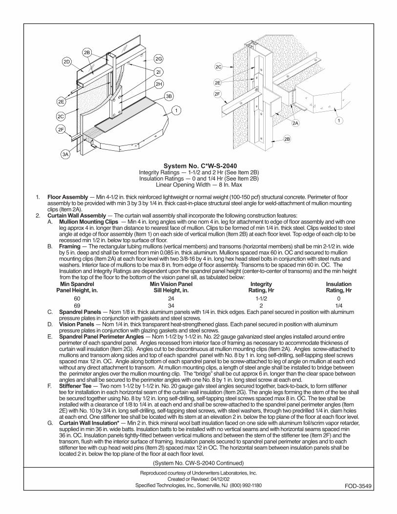
System No. CW-S-2040Integrity Ratings — 1-1/2 and 2 Hr (See Item 2B)Insulation Ratings — 0 and 1/4 Hr (See Item 2B)
Linear Opening Width — 8 In. Max
1. Floor Assembly — Min 4-1/2 in. thick reinforced lightweight or normal weight (100-150 pcf) structural concrete. Perimeter of floor assembly to be provided with min 3 by 3 by 1/4 in. thick cast-in-place structural steel angle for weld-attachment of mullion mounting clips (Item 2A).
2. Curtain Wall Assembly — The curtain wall assembly shall incorporate the following construction features:A. Mullion Mounting Clips — Min 4 in. long angles with one nom 4 in. leg for attachment to edge of floor assembly and with one
leg approx 4 in. longer than distance to nearest face of mullion. Clips to be formed of min 1/4 in. thick steel. Clips welded to steel angle at edge of floor assembly (Item 1) on each side of vertical mullion (Item 2B) at each floor level. Top edge of each clip to be recessed min 1/2 in. below top surface of floor.
B. Framing — The rectangular tubing mullions (vertical members) and transoms (horizontal members) shall be min 2-1/2 in. wide by 5 in. deep and shall be formed from min 0.085 in. thick aluminum. Mullions spaced max 60 in. OC and secured to mullion mounting clips (Item 2A) at each floor level with two 3/8-16 by 4 in. long hex head steel bolts in conjunction with steel nuts and washers. Interior face of mullions to be max 8 in. from edge of floor assembly. Transoms to be spaced min 60 in. OC. The Insulation and Integrity Ratings are dependent upon the spandrel panel height (center-to-center of transoms) and the min height
from the top of the floor to the bottom of the vision panel sill, as tabulated below:Min Spandrel
Panel Height, in.Min Vision Panel
Sill Height, in.Integrity
Rating, HrInsulationRating, Hr
60 24 1-1/2 069 34 2 1/4
C. Spandrel Panels — Nom 1/8 in. thick aluminum panels with 1/4 in. thick edges. Each panel secured in position with aluminum pressure plates in conjunction with gaskets and steel screws.
D. Vision Panels — Nom 1/4 in. thick transparent heat-strengthened glass. Each panel secured in position with aluminum pressure plates in conjunction with glazing gaskets and steel screws.
E. Spandrel Panel Perimeter Angles — Nom 1-1/2 by 1-1/2 in. No. 22 gauge galvanized steel angles installed around entire perimeter of each spandrel panel. Angles recessed from interior face of framing as necessary to accommodate thickness of curtain wall insulation (Item 2G). Angles cut to be discontinuous at mullion mounting clips (Item 2A). Angles screw-attached to mullions and transom along sides and top of each spandrel panel with No. 8 by 1 in. long self-drilling, self-tapping steel screws spaced max 12 in. OC. Angle along bottom of each spandrel panel to be screw-attached to leg of angle on mullion at each end without any direct attachment to transom. At mullion mounting clips, a length of steel angle shall be installed to bridge between the perimeter angles over the mullion mounting clip. The “bridge” shall be cut approx 6 in. longer than the clear space between angles and shall be secured to the perimeter angles with one No. 8 by 1 in. long steel screw at each end.
F. Stiffener Tee — Two nom 1-1/2 by 1-1/2 in. No. 20 gauge galv steel angles secured together, back-to-back, to form stiffener tee for installation in each horizontal seam of the curtain wall insulation (Item 2G). The angle legs forming the stem of the tee shall be secured together using No. 8 by 1/2 in. long self-drilling, self-tapping steel screws spaced max 8 in. OC. The tee shall be installed with a clearance of 1/8 to 1/4 in. at each end and shall be screw-attached to the spandrel panel perimeter angles (Item 2E) with No. 10 by 3/4 in. long self-drilling, self-tapping steel screws, with steel washers, through two predrilled 1/4 in. diam holes at each end. One stiffener tee shall be located with its stem at an elevation 2 in. below the top plane of the floor at each floor level.
G. Curtain Wall Insulation* — Min 2 in. thick mineral wool batt insulation faced on one side with aluminum foil/scrim vapor retarder, supplied in min 36 in. wide batts. Insulation batts to be installed with no vertical seams and with horizontal seams spaced min 36 in. OC. Insulation panels tightly-fitted between vertical mullions and between the stem of the stiffener tee (Item 2F) and the transom, flush with the interior surface of framing. Insulation panels secured to spandrel panel perimeter angles and to each stiffener tee with cup head weld pins (Item 2I) spaced max 12 in OC. The horizontal seam between insulation panels shall be located 2 in. below the top plane of the floor at each floor level.
Reproduced courtesy of Underwriters Laboratories, Inc.Created or Revised: 04/12/02
Specified Technologies, Inc., Somerville, NJ (800) 992-1180 FOD-3549
(System No. CW-S-2040 Continued)
FIBREX INSULATIONS INC — FBX CW90 Curtain Wall InsulationH. Framing Covers — Curtain Wall Insulation* — Min 8 in. wide strips cut from the same min 2 in. thick mineral wool batt
insulation used for the curtain wall insulation (Item 2G). Framing covers to be centered over mullions and secured to the spandrel panel perimeter angles with cup head weld pins (Item 2I) spaced max 12 in. OC. Where more than one spandrel panel occurs between vertically separated vision panels, the horizontal transom between spandrel panels shall also be covered with an 8 in. wide framing cover in the same manner as on the vertical mullions. Framing covers on mullions to abut the mineral wool batt safing material (Item 3A) above and below floor.
FIBREX INSULATIONS INC — FBX CW90 Curtain Wall InsulationI. Weld Pin — No. 12 gauge galv steel weld pin with nom 1-3/16 in. diam galv steel cup head. Cup head weld pins provided
in two lengths. One length to be equal to thickness of curtain wall insulation (Item 2G) and second length to be equal to thickness of curtain wall insulation plus thickness of framing cover (Item 2H). Cup head weld pins inserted through curtain wall insulation and mullion covers and welded to spandrel panel perimeter angles max 12 in. OC.
3. Safing System — The safing system shall incorporate the following construction features:A. Forming Material* — Nom 4 pcf density mineral wool batt insulation. Batt sections cut to a width equal to the thickness of the
floor and stacked to a thickness which is min 20 percent greater than the width of linear gap between the curtain wall insulation and the edge of the concrete floor slab. The forming material is compressed and inserted cut-edge-first into linear gap such that its top and bottom surfaces are flush with the surfaces of the floor assembly. A max of one tightly-butted seam is permitted between mullions. Additional pieces of forming material to be friction-fit into spaces between mullion mounting clips at each mullion location.
FIBREX INSULATIONS INC — FBX Safing InsulationB. Fill, Void or Cavity Material* — Min 1/8 in. wet thickness of fill material spray- applied over top of forming material and lapping
min 1/2 in. onto the top surface of the floor and onto the curtain wall insulation and framing covers. SPECIFIED TECHNOLOGIES INC — SpecSeal AS200 Elastomeric Spray.
*Bearing the UL Classification Marking
(System No. CW-S-2040 Continued)
FOD-3549
Reproduced courtesy of Underwriters Laboratories, Inc.Created or Revised: 04/12/02
Specified Technologies, Inc., Somerville, NJ (800) 992-1180
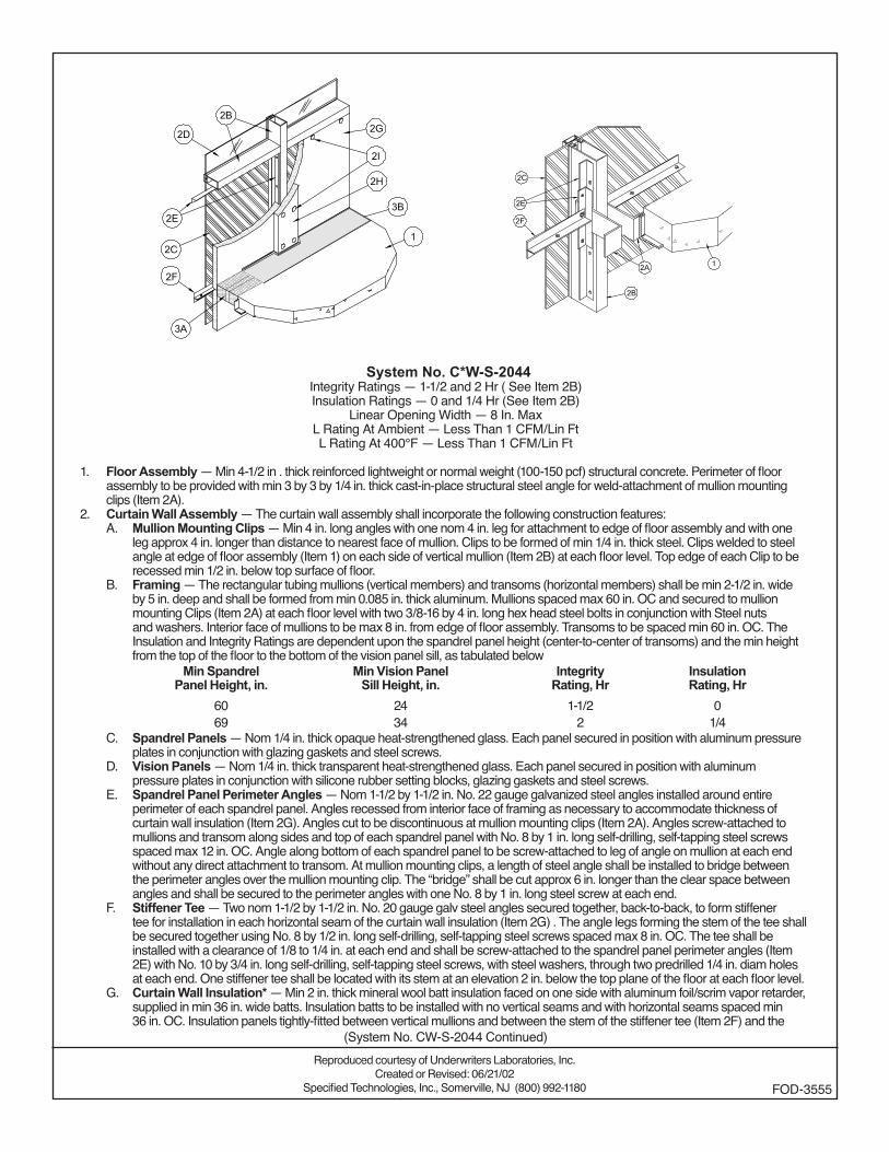
System No. CW-S-2044Integrity Ratings — 1-1/2 and 2 Hr ( See Item 2B) Insulation Ratings — 0 and 1/4 Hr (See Item 2B)
Linear Opening Width — 8 In. MaxL Rating At Ambient — Less Than 1 CFM/Lin FtL Rating At 400°F — Less Than 1 CFM/Lin Ft
1. Floor Assembly — Min 4-1/2 in . thick reinforced lightweight or normal weight (100-150 pcf) structural concrete. Perimeter of floor assembly to be provided with min 3 by 3 by 1/4 in. thick cast-in-place structural steel angle for weld-attachment of mullion mounting clips (Item 2A).
2. Curtain Wall Assembly — The curtain wall assembly shall incorporate the following construction features:A. Mullion Mounting Clips — Min 4 in. long angles with one nom 4 in. leg for attachment to edge of floor assembly and with one
leg approx 4 in. longer than distance to nearest face of mullion. Clips to be formed of min 1/4 in. thick steel. Clips welded to steel angle at edge of floor assembly (Item 1) on each side of vertical mullion (Item 2B) at each floor level. Top edge of each Clip to be recessed min 1/2 in. below top surface of floor.
B. Framing — The rectangular tubing mullions (vertical members) and transoms (horizontal members) shall be min 2-1/2 in. wide by 5 in. deep and shall be formed from min 0.085 in. thick aluminum. Mullions spaced max 60 in. OC and secured to mullion mounting Clips (Item 2A) at each floor level with two 3/8-16 by 4 in. long hex head steel bolts in conjunction with Steel nuts and washers. Interior face of mullions to be max 8 in. from edge of floor assembly. Transoms to be spaced min 60 in. OC. The Insulation and Integrity Ratings are dependent upon the spandrel panel height (center-to-center of transoms) and the min height from the top of the floor to the bottom of the vision panel sill, as tabulated below
Min SpandrelPanel Height, in.
Min Vision PanelSill Height, in.
IntegrityRating, Hr
InsulationRating, Hr
60 24 1-1/2 069 34 2 1/4
C. Spandrel Panels — Nom 1/4 in. thick opaque heat-strengthened glass. Each panel secured in position with aluminum pressure plates in conjunction with glazing gaskets and steel screws.
D. Vision Panels — Nom 1/4 in. thick transparent heat-strengthened glass. Each panel secured in position with aluminum pressure plates in conjunction with silicone rubber setting blocks, glazing gaskets and steel screws.
E. Spandrel Panel Perimeter Angles — Nom 1-1/2 by 1-1/2 in. No. 22 gauge galvanized steel angles installed around entire perimeter of each spandrel panel. Angles recessed from interior face of framing as necessary to accommodate thickness of curtain wall insulation (Item 2G). Angles cut to be discontinuous at mullion mounting clips (Item 2A). Angles screw-attached to mullions and transom along sides and top of each spandrel panel with No. 8 by 1 in. long self-drilling, self-tapping steel screws spaced max 12 in. OC. Angle along bottom of each spandrel panel to be screw-attached to leg of angle on mullion at each end without any direct attachment to transom. At mullion mounting clips, a length of steel angle shall be installed to bridge between the perimeter angles over the mullion mounting clip. The “bridge” shall be cut approx 6 in. longer than the clear space between angles and shall be secured to the perimeter angles with one No. 8 by 1 in. long steel screw at each end.
F. Stiffener Tee — Two nom 1-1/2 by 1-1/2 in. No. 20 gauge galv steel angles secured together, back-to-back, to form stiffener tee for installation in each horizontal seam of the curtain wall insulation (Item 2G) . The angle legs forming the stem of the tee shall be secured together using No. 8 by 1/2 in. long self-drilling, self-tapping steel screws spaced max 8 in. OC. The tee shall be installed with a clearance of 1/8 to 1/4 in. at each end and shall be screw-attached to the spandrel panel perimeter angles (Item 2E) with No. 10 by 3/4 in. long self-drilling, self-tapping steel screws, with steel washers, through two predrilled 1/4 in. diam holes at each end. One stiffener tee shall be located with its stem at an elevation 2 in. below the top plane of the floor at each floor level.
G. Curtain Wall Insulation* — Min 2 in. thick mineral wool batt insulation faced on one side with aluminum foil/scrim vapor retarder, supplied in min 36 in. wide batts. Insulation batts to be installed with no vertical seams and with horizontal seams spaced min 36 in. OC. Insulation panels tightly-fitted between vertical mullions and between the stem of the stiffener tee (Item 2F) and the
Reproduced courtesy of Underwriters Laboratories, Inc.Created or Revised: 06/21/02
Specified Technologies, Inc., Somerville, NJ (800) 992-1180 FOD-3555
(System No. CW-S-2044 Continued)
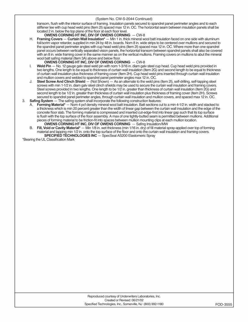
transom, flush with the interior surface of framing. Insulation panels secured to spandrel panel perimeter angles and to each stiffener tee with cup head weld pins (Item 2I) spaced max 12 in. OC. The horizontal seam between insulation panels shall be located 2 in. below the top plane of the floor at each floor level.
OWENS CORNING HT INC, DIV OF OWENS CORNING — CW-8H. Framing Covers — Curtain Wall Insulation* — Min 1 in. thick mineral wool batt insulation faced on one side with aluminum
foil/scrim vapor retarder, supplied in min 24 by 48 in. boards. Nom 8 in. wide strips to be centered over mullions and secured to the spandrel panel perimeter angles with cup head weld pins (Item 2I) spaced max 12 in. OC. Where more than one spandrel panel occurs between vertically separated vision panels, the horizontal transom between spandrel panels shall also be covered with an 8 in. wide framing cover in the same manner as on the vertical mullions. Framing covers on mullions to abut the mineral wool batt safing material (Item 3A) above and below floor.
OWENS CORNING HT INC, DIV OF OWENS CORNING — CW-8I. Weld Pin — No. 12 gauge galv steel weld pin with nom 1-3/16 in. diam galv steel cup head. Cup head weld pins provided in
two lengths. One length to be equal to thickness of curtain wall insulation (Item 2G) and second length to be equal to thickness of curtain wall insulation plus thickness of framing cover (Item 2H). Cup head weld pins inserted through curtain wall insulation and mullion covers and welded to spandrel panel perimeter angles max 12 in. OC.
J. Steel Screw And Clinch Shield — (Not Shown) — As an alternate to the weld pins (Item 2I), self-drilling, self-tapping steel screws with min 1-1/2 in. diam galv steel clinch shields may be used to secure the curtain wall insulation and framing covers. Steel screws provided in two lengths. One length to be 1/2 in. greater than thickness of curtain wall insulation (Item 2G) and second length to be 1/2 in. greater than thickness of curtain wall insulation plus thickness of framing cover (Item 2H). Screws secured to spandrel panel perimeter angles, through curtain wall insulation and mullion covers, and spaced max 12 in. OC.
3. Safing System — The safing system shall incorporate the following construction features:A. Forming Material* — Nom 4 pcf density mineral wool batt insulation. Batt sections cut to a min 4-1/2 in. width and stacked to
a thickness which is min 20 percent greater than the width of linear gap between the curtain wall insulation and the edge of the concrete floor slab. The forming material is compressed and inserted cut-edge-first into linear gap such that its top surface is flush with the top surface of the floor assembly. A max of one tightly-butted seam is permitted between mullions. Additional pieces of forming material to be friction-fit into spaces between mullion mounting clips at each mullion location.
OWENS CORNING HT INC, DIV OF OWENS CORNING — Safing Insulation/MWB. Fill, Void or Cavity Material* — Min 1/8 in. wet thickness (min 1/16 in. dry) of fill material spray-applied over top of forming
material and lapping min 1/2 in. onto the top surface of the floor and onto the curtain wall insulation and framing covers. SPECIFIED TECHNOLOGIES INC — SpecSeal AS200 Elastomeric Spray
*Bearing the UL Classification Mark
(System No. CW-S-2044 Continued)
Reproduced courtesy of Underwriters Laboratories, Inc.Created or Revised: 06/21/02
Specified Technologies, Inc., Somerville, NJ (800) 992-1180 FOD-3555
System No. CW-S-2045Integrity Ratings — 1-1/2 and 2 Hr (See Item 2B) Insulation Ratings — 0 and 1/4 Hr (See Item 2B)
Linear Opening Width — 8 In. MaxL Rating At Ambient — Less Than 1 CFM/Lin FtL Rating At 400°F — Less Than 1 CFM/Lin Ft
1. Floor Assembly — Min 4-1/2 in. thick reinforced lightweight or normal weight (100-150 pcf) structural concrete. Perimeter of floor assembly to be provided with min 3 by 3 by 1/4 in. thick cast-in-place structural steel angle for weld-attachment of mullion mounting clips (Item 2A).
2. Curtain Wall Assembly — The curtain wall assembly shall incorporate the following construction features:A. Mullion Mounting Clips — Min 4 in. long angles with one nom 4 in. leg for attachment to edge of floor assembly and with one
leg approx 4 in. longer than distance to nearest face of mullion. Clips to be formed of min 1/4 in. thick steel. Angles Clips welded to steel angle at edge of floor assembly (Item 1) on each side of vertical mullion (Item 2B) at each floor level. Top edge of each clip to be recessed min 1/2 in. below top surface of floor.
B. Framing — The rectangular tubing mullions (vertical members) and transoms (horizontal members) shall be min 2-1/2 in. wide by 5 in. deep and shall be formed from min 0.085 in. thick aluminum. Mullions spaced max 60 in. OC and secured to mullion mounting clips (Item 2A) at each floor level with two 3/8-16 by 4 in. long hex head steel bolts in conjunction with steel nuts and washers . Interior face of mullions to be max 8 in. from edge of floor assembly. Transoms to be spaced min 60 in. OC. The Insulation and Integrity Ratings are dependent upon the spandrel panel height (center-to-center of transoms) and the min height from the top of the floor to the bottom of the vision panel sill, as tabulated below:
Min Spandrel Panel Height, in.
Min Vision PanelSill Height, in.
IntegrityRating, Hr
InsulationRating, Hr
60 24 1-1/2 069 34 2 1/4
C. Spandrel Panels — Nom 1/8 in. thick aluminum panels with 1/4 in. thick edges. Each panel secured in position with aluminum pressure plates in conjunction with gaskets and steel screws.
D. Vision Panels — Nom 1/4 in. thick transparent heat-strengthened glass. Each panel secured in position with aluminum pressure plates in conjunction with silicone rubber setting blocks, glazing gaskets and steel screws.
E. Spandrel Panel Perimeter Angles — Nom 1-1/2 by 1-1/2 in. No. 22 gauge galvanized steel angles installed around entire perimeter of each spandrel panel. Angles recessed from interior face of framing as necessary to accommodate thickness of curtain wall insulation (Item 2G). Angles cut to be discontinuous at mullion mounting clips (Item 2A). Angles screw-attached to mullions and transom along sides and top of each spandrel panel with No. 8 by 1 in. long self-drilling, self-tapping steel screws spaced max 12 in. OC. Angle along bottom of each spandrel panel to be screw-attached to leg of angle on mullion at each end without any direct attachment to transom. At mullion mounting clips, a length of steel angle shall be installed to bridge between the perimeter angles over the mullion mounting clip. The “bridge” shall be cut approx 6 in. longer than the clear space between angles and shall be secured to the perimeter angles with one No. 8 by 1 in. long steel screw at each end.
F. Stiffener Tee — Two nom 1-1/2 by 1-1/2 in. No. 20 gauge galv steel angles secured together, back-to-back, to form stiffener tees for installation in each horizontal seam of the curtain wall insulation (Item 2G) . The angle legs forming the stem of the tee shall be secured together using No. 8 by 1/2 in. long self-drilling, self-tapping steel screws spaced max 8 in. OC. The tee shall be installed with a clearance of 1/8 to 1/4 in. at each end and shall be screw-attached to the spandrel panel perimeter angles (Item 2E) with No. 10 by 3/4 in. long self-drilling, self-tapping steel screws, with steel washers, through two predrilled 1/4 in. diam holes at each end. One stiffener tee shall be located with its stem at an elevation 2 in. below the top plane of the floor at each floor level.
G. Curtain Wall Insulation* — Min 2 in. thick mineral wool batt insulation faced on one side with aluminum foil/scrim vapor retarder, supplied in min 36 in. wide batts. Insulation batts to be installed with no vertical seams and with horizontal seams spaced min 36 in. OC. Insulation panels tightly-fitted between vertical mullions and between the stem of the stiffener tee (Item 2F) and the
Reproduced courtesy of Underwriters Laboratories, Inc.Created or Revised: 06/21/02
Specified Technologies, Inc., Somerville, NJ (800) 992-1180 FOD-3556
(System No. CW-S-2045 Continued)
System No. CW-S-2050Integrity Rating — 3 Hr
Insulation Rating — 1/4 HrLinear Opening Width — 8 In. Max
L Rating At Ambient — Less Than 1 CFM/Lin FtL Rating At 400°F — Less Than 1 CFM/Lin Ft
1. Floor Assembly — Min 4-1/2 in. thick reinforced lightweight or normal weight (100-150 pcf) structural concrete. Perimeter of floor assembly to be provided with min 3 by 3 by 1/4 in. thick cast-in-place structural steel angle for weld-attachment of mullion mounting clips (Item 2A).
2. Curtain Wall Assembly — The curtain wall assembly shall incorporate the following construction features: A. Mullion Mounting Clips — Nom 4 in. long angles with one nom 4 in. leg for attachment to edge of floor assembly and with one
leg approx 4 in. longer than the distance from the floor edge to the mullion. Clips to be formed of min 1/4 in. thick steel. Clips welded to steel angle at edge of floor assembly (Item 1) on each side of vertical mullion (Item 2B) at each floor level. Top edge of each clip to be recessed min 1/2 in. below top surface of floor.
B. Framing — The rectangular tubing mullions (vertical members) and transoms (horizontal members) shall be min 2-1/2 in. wide by 5 in. deep and shall be formed from min 0.100 in. thick aluminum. Mullions spaced max 60 in. OC and secured to mullion mounting clips (Item 2A) at each floor level with two 3/8-16 by 4 in. long hex head steel bolts in conjunction with steel nuts and washers. Interior face of mullions to be max 8 in. from edge of floor assembly. Transoms to be spaced min 66 in. OC. The minimum height from the top of the floor to the bottom of the vision panel sill is 33 in.
C. Spandrel Panels — Nom 1/4 in. thick or nom 1 in. thick (double pane) heat-strengthened glass panels. Each panel installed on silicone rubber setting blocks and secured in position with aluminum pressure plates in conjunction with glazing gaskets and steel screws.
D. Vision Panels — Nom 1 in. thick insulated glass units with two layers of nom 1/4 in. thick transparent heat-strengthened glass separated by a 1/2 in. air space. Each panel installed on silicone rubber setting blocks and secured in position with aluminum pressure plates in conjunction with glazing gaskets and steel screws.
E. Stiffener Tee Attachment Angles — Nom 1-1/2 by 1-1/2 by 4 in. long No. 22 gauge galvanized steel angles. Each angle secured to steel mullion mounting clip (Item 2A) with two No. 10 by min 1/2 in. long self-tapping steel screws. Angle recessed from interior face of framing as necessary to accommodate the thickness of curtain wall insulation (Item 2H).
F. Stiffener Tee — Two nom 1-1/2 by 1-1/2 in. No. 22 gauge galv steel angles secured together, back-to-back, to form stiffener tee for installation between mullions at each floor level to restrain curtain wall insulation (Item 2H) against outward movement when forming material (Item 3A) is installed. The angle legs forming the stem of the tee shall be secured together using No. 8 by 1/2 in. long self-drilling, self-tapping steel screws spaced max 8 in. OC. The tee shall be installed with a clearance of 1/8 to 1/4 in. at each end and shall be screw-attached to the stiffener tee attachment angles (Item 2E) with No. 10 by min 1/2 in. long self-drilling, self-tapping steel screws, with steel washers, through two predrilled 1/4 in. diam holes at each end. Each stiffener tee shall be located with its stem at an elevation 3 in. below the top plane of the floor.
G. Insulation Hangers — Min 4-1/2 in. long No. 12 gauge steel pins swaged to nom 2 by 2 by 2 in. long No. 28 gauge galvanized steel angles. Insulation hangers screw-attached to mullions and transoms with two No. 10 by min 1/2 in. long self-drilling, self-tapping steel screws per hanger. Insulation hangers to be located in each corner of spandrel panel and spaced max 12 in. OC along sides and top of each spandrel panel. No insulation hangers to be used on the transom at the head (lintel) of a vision panel.
H. Curtain Wall Insulation* — Min 2 in. thick mineral wool batt insulation faced on one side with aluminum foil/scrim vapor retarder, supplied in min 36 in. wide batts. Insulation batts to be installed with no vertical seams and with horizontal seams spaced min 36 in. OC. Insulation panels tightly-fitted between vertical mullions and between the stem of the stiffener tee (Item 2F) and the transom, flush with the interior surface of framing. Insulation panels impaled on steel pins (Item 2G) and secured in place with nom 1-1/2 in. diam steel self-locking washers (“clinch shields”). The horizontal seam between insulation panels shall be located 3 in. below the top plane of the floor at each floor level.
OWENS CORNING HT INC, DIV OF OWENS CORNING — CW-8
Reproduced courtesy of Underwriters Laboratories, Inc.Created or Revised: 09/16/02
Specified Technologies, Inc., Somerville, NJ (800) 992-1180 FOD-3569
2G
2F
2E
2C
2A
2B
1
1
2B
2C
2D
2F
2J
3A
3B
2G
2H
(System No. CW-S-2050 Continued)

(System No. CW-S-2050 Continued)
Reproduced courtesy of Underwriters Laboratories, Inc.Created or Revised: 09/16/02
Specified Technologies, Inc., Somerville, NJ (800) 992-1180 FOD-3569
J. Framing Covers — Curtain Wall Insulation* — Min 1 in. thick mineral wool batt insulation faced on one side with aluminum foil/scrim vapor retarder, supplied in min 24 by 48 in. boards. Nom 8 in. wide strips to be centered over mullions and impaled on the same pins (Item 2G) and secured in place with nom 1-1/2 in. diam steel self-locking washers (“clinch shields”). Where more than one spandrel panel occurs between vertically separated vision panels, the horizontal transom between spandrel panels shall also be covered with an 8 in. wide framing cover in the same manner as on the vertical mullions. Framing covers on mullions to abut the mineral wool batt safing material (Item 3A) above and below floor.
OWENS CORNING HT INC, DIV OF OWENS CORNING — CW-83. Safing System — The safing system shall incorporate the following construction features:
A. Forming Material* — Nom 4 pcf density mineral wool batt insulation. Batt sections cut to a min 4-1/2 in. width and stacked to a thickness, which is min 25 percent greater than the width of linear gap between the curtain wall insulation and the edge of the concrete floor slab to attain a min 20 percent compression in the thickness direction. The forming material is compressed and inserted cut-edge-first into linear gap such that its top surface is flush with the top surface of the floor assembly. A max of one tightly-butted seam is permitted between mullions. Additional pieces of forming material to be friction-fit into spaces between mullion mounting clips at each mullion location.
OWENS CORNING HT INC, DIV OF OWENS CORNING — Safing InsulationB. Fill, Void or Cavity Material* — Min 1/8 in. wet thickness (min 1/16 in. dry thickness) of fill material spray-applied over top of
forming material and lapping min 1/2 in. onto the top surface of the floor and onto the curtain wall insulation and framing covers. SPECIFIED TECHNOLOGIES INC — SpecSeal AS200 Elastomeric Spray
*Bearing the UL Classification Mark
transom, flush with the interior surface of framing. Insulation panels secured to spandrel panel perimeter angles and to each stiffener tee with cup head weld pins (Item 2I) spaced max 12 in OC. The horizontal seam between insulation panels shall be located 2 in. below the top plane of the floor at each floor level.
OWENS CORNING HT INC, DIV OF OWENS CORNING — CW-8H. Framing Covers — Curtain Wall Insulation* — Min 1 in. thick mineral wool batt insulation faced on one side with aluminum
foil/scrim vapor retarder, supplied in min 24 by 48 in. boards. Nom 8 in. wide strips to be centered over mullions and secured to the spandrel panel perimeter angles with cup head weld pins (Item 2I) spaced max 12 in. OC. Where more than one spandrel panel occurs between vertically separated vision panels, the horizontal transom between spandrel panels shall also be covered with an 8 in. wide framing cover in the same manner as on the vertical mullions. Framing covers on mullions to abut the mineral wool batt safing material (Item 3A) above and below floor.
OWENS CORNING HT INC, DIV OF OWENS CORNING — Safing Insulation/MWI. Weld Pin — No. 12 gauge galv steel weld pin with nom 1-3/16 in. diam galv steel cup head. Cup head weld pins provided in
two lengths. One length to be equal to thickness of curtain wall insulation (Item 2G) and second length to be equal to thickness of curtain wall insulation plus thickness of framing cover (Item 2H). Cup head weld pins inserted through curtain wall insulation and mullion covers and welded to spandrel panel perimeter angles max 12 in. OC.
J. Steel Screw And Clinch Shield — (Not Shown) — As an alternate to the weld pins (Item 2I), self-drilling, self-tapping steel screws with min 1-1/2 in. diam galv steel clinch shields may be used to secure the curtain wall insulation and framing covers. Steel screws provided in two lengths. One length to be 1/2 in. greater than thickness of curtain wall insulation (Item 2G) and second length to be 1/2 in. greater than thickness of curtain wall insulation plus thickness of framing cover (Item 2H). Screws secured to spandrel panel perimeter angles, through curtain wall insulation and mullion covers, and spaced max 12 in. OC.
3. Safing System — The safing system shall incorporate the following construction features:A. Forming Material* — Nom 4 pcf density mineral wool batt insulation. Batt sections cut to a min 4-1/2 in. width and stacked to
a thickness which is min 20 percent greater than the width of linear gap between the curtain wall insulation and the edge of the concrete floor slab. The forming material is compressed and inserted cut-edge-first into linear gap such that its top surface is flush with the top surface of the floor assembly. A max of one tightly-butted seam is permitted between mullions. Additional pieces of forming material to be friction-fit into spaces between mullion mounting clips at each mullion location.
OWENS CORNING HT INC, DIV OF OWENS CORNING — Safing Insulation/MWB. Fill, Void or Cavity Material* — Min 1/8 in. wet thickness (min 1/16 in. dry) of fill material spray- applied over top of forming
material and lapping min 1/2 in. onto the top surface of the floor and onto the curtain wall insulation and framing covers. SPECIFIED TECHNOLOGIES INC — SpecSeal AS200 Elastomeric Spray.
*Bearing the UL Classification Mark
(System No. CW-S-2045 Continued)
Reproduced courtesy of Underwriters Laboratories, Inc.Created or Revised: 06/21/02
Specified Technologies, Inc., Somerville, NJ (800) 992-1180 FOD-3556
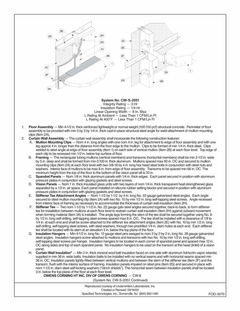
System No. CW-S-2051Integrity Rating — 3 Hr
Insulation Rating — 1/4 HrLinear Opening Width — 8 In. Max
L Rating At Ambient — Less Than 1 CFM/Lin FtL Rating At 400°F — Less Than 1 CFM/Lin Ft
1. Floor Assembly — Min 4-1/2 in. thick reinforced lightweight or normal weight (100-150 pcf) structural concrete. Perimeter of floor assembly to be provided with min 3 by 3 by 1/4 in. thick cast-in-place structural steel angle for weld-attachment of mullion mounting clips (Item 2A).
2. Curtain Wall Assembly — The curtain wall assembly shall incorporate the following construction features: A. Mullion Mounting Clips — Nom 4 in. long angles with one nom 4 in. leg for attachment to edge of floor assembly and with one
leg approx 4 in. longer than the distance from the floor edge to the mullion. Clips to be formed of min 1/4 in. thick steel. Clips welded to steel angle at edge of floor assembly (Item 1) on each side of vertical mullion (Item 2B) at each floor level. Top edge of each clip to be recessed min 1/2 in. below top surface of floor.
B. Framing — The rectangular tubing mullions (vertical members) and transoms (horizontal members) shall be min 2-1/2 in. wide by 5 in. deep and shall be formed from min 0.100 in. thick aluminum. Mullions spaced max 60 in. OC and secured to mullion mounting clips (Item 2A) at each floor level with two 3/8-16 by 4 in. long hex head steel bolts in conjunction with steel nuts and washers. Interior face of mullions to be max 8 in. from edge of floor assembly. Transoms to be spaced min 66 in. OC. The minimum height from the top of the floor to the bottom of the vision panel sill is 33 in.
C. Spandrel Panels — Nom 1/8 in. thick aluminum panels with 1/4 in. thick edges. Each panel secured in position with aluminum pressure plates in conjunction with glazing gaskets and steel screws.
D. Vision Panels — Nom 1 in. thick insulated glass units with two layers of nom 1/4 in. thick transparent heat-strengthened glass separated by a 1/2 in. air space. Each panel installed on silicone rubber setting blocks and secured in position with aluminum pressure plates in conjunction with glazing gaskets and steel screws.
E. Stiffener Tee Attachment Angles — Nom 1-1/2 by 1-1/2 by 4 in. long No. 22 gauge galvanized steel angles. Each angle secured to steel mullion mounting clip (Item 2A) with two No. 10 by min 1/2 in. long self-tapping steel screws. Angle recessed from interior face of framing as necessary to accommodate the thickness of curtain wall insulation (Item 2H).
F. Stiffener Tee — Two nom 1-1/2 by 1-1/2 in. No. 22 gauge galv steel angles secured together, back-to-back, to form stiffener tee for installation between mullions at each floor level to restrain curtain wall insulation (Item 2H) against outward movement when forming material (Item 3A) is installed. The angle legs forming the stem of the tee shall be secured together using No. 8 by 1/2 in. long self-drilling, self-tapping steel screws spaced max 8 in. OC. The tee shall be installed with a clearance of 1/8 to 1/4 in. at each end and shall be screw-attached to the stiffener tee attachment angles (Item 2E) with No. 10 by min 1/2 in. long self-drilling, self-tapping steel screws, with steel washers, through two predrilled 1/4 in. diam holes at each end. Each stiffener tee shall be located with its stem at an elevation 3 in. below the top plane of the floor.
G. Insulation Hangers — Min 4-1/2 in. long No. 12 gauge steel pins swaged to nom 2 by 2 by 2 in. long No. 28 gauge galvanized steel angles. Insulation hangers screw-attached to mullions and transoms with two No. 10 by min 1/2 in. long self-drilling, self-tapping steel screws per hanger. Insulation hangers to be located in each corner of spandrel panel and spaced max 12 in. OC along sides and top of each spandrel panel. No insulation hangers to be used on the transom at the head (lintel) of a vision panel.
H. Curtain Wall Insulation* — Min 2 in. thick mineral wool batt insulation faced on one side with aluminum foil/scrim vapor retarder, supplied in min 36 in. wide batts. Insulation batts to be installed with no vertical seams and with horizontal seams spaced min 36 in. OC. Insulation panels tightly-fitted between vertical mullions and between the stem of the stiffener tee (Item 2F) and the transom, flush with the interior surface of framing. Insulation panels impaled on steel pins (Item 2G) and secured in place with nom 1-1/2 in. diam steel self-locking washers (“clinch shields”). The horizontal seam between insulation panels shall be located 3 in. below the top plane of the floor at each floor level.
OWENS CORNING HT INC, DIV OF OWENS CORNING — CW-8
Reproduced courtesy of Underwriters Laboratories, Inc.Created or Revised: 09/16/02
Specified Technologies, Inc., Somerville, NJ (800) 992-1180 FOD-3570
(System No. CW-S-2051 Continued)
(System No. CW-S-2051 Continued)
Reproduced courtesy of Underwriters Laboratories, Inc.Created or Revised: 09/16/02
Specified Technologies, Inc., Somerville, NJ (800) 992-1180 FOD-3570
J. Framing Covers — Curtain Wall Insulation* — Min 1 in. thick mineral wool batt insulation faced on one side with aluminum foil/scrim vapor retarder, supplied in min 24 by 48 in. boards. Nom 8 in. wide strips to be centered over mullions and impaled on the same pins (Item 2G) and secured in place with nom 1-1/2 in. diam steel self-locking washers (“clinch shields”). Where more than one spandrel panel occurs between vertically separated vision panels, the horizontal transom between spandrel panels shall also be covered with an 8 in. wide framing cover in the same manner as on the vertical mullions. Framing covers on mullions to abut the mineral wool batt safing material (Item 3A) above and below floor.
OWENS CORNING HT INC, DIV OF OWENS CORNING — CW-83. Safing System — The safing system shall incorporate the following construction features:
A. Forming Material* — Nom 4 pcf density mineral wool batt insulation. Batt sections cut to a min 4-1/2 in. width and stacked to a thickness, which is min 25 percent greater than the width of linear gap between the curtain wall insulation and the edge of the concrete floor slab to attain a min 20 percent compression in the thickness direction. The forming material is compressed and inserted cut-edge-first into linear gap such that its top surface is flush with the top surface of the floor assembly. A max of one tightly-butted seam is permitted between mullions. Additional pieces of forming material to be friction-fit into spaces between mullion mounting clips at each mullion location.
OWENS CORNING HT INC, DIV OF OWENS CORNING — Safing InsulationB. Fill, Void or Cavity Material* — Min 1/8 in. wet thickness (min 1/16 in. dry thickness) of fill material spray-applied over top of
forming material and lapping min 1/2 in. onto the top surface of the floor and onto the curtain wall insulation and framing covers. SPECIFIED TECHNOLOGIES INC — SpecSeal AS200 Elastomeric Spray
*Bearing the UL Classification Mark
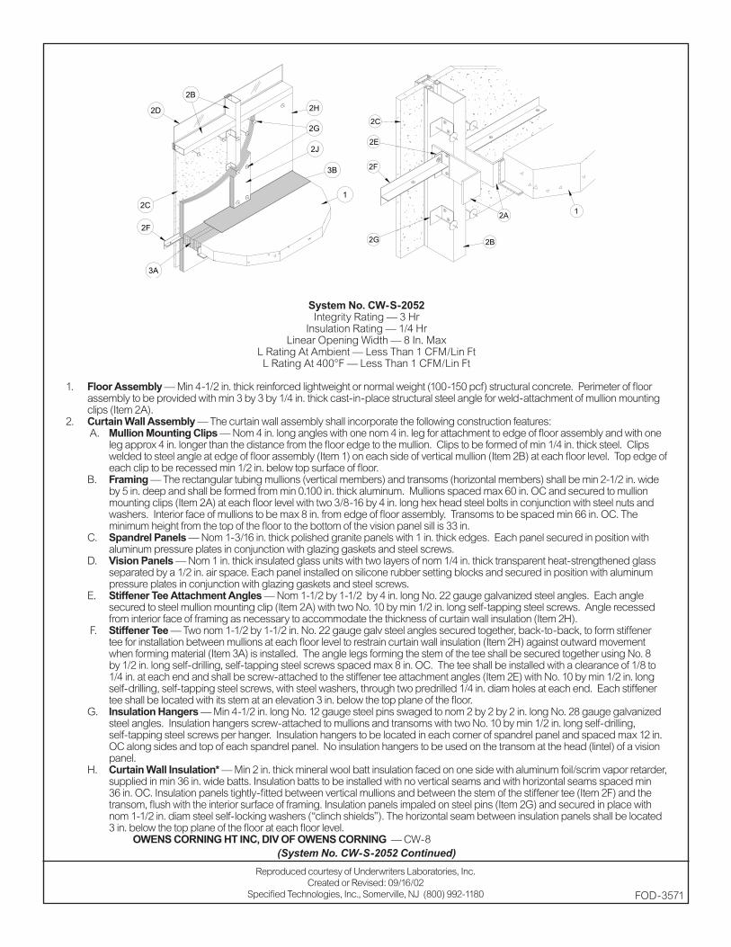
System No. CW-S-2052Integrity Rating — 3 Hr
Insulation Rating — 1/4 HrLinear Opening Width — 8 In. Max
L Rating At Ambient — Less Than 1 CFM/Lin FtL Rating At 400°F — Less Than 1 CFM/Lin Ft
1. Floor Assembly — Min 4-1/2 in. thick reinforced lightweight or normal weight (100-150 pcf) structural concrete. Perimeter of floor assembly to be provided with min 3 by 3 by 1/4 in. thick cast-in-place structural steel angle for weld-attachment of mullion mounting clips (Item 2A).
2. Curtain Wall Assembly — The curtain wall assembly shall incorporate the following construction features: A. Mullion Mounting Clips — Nom 4 in. long angles with one nom 4 in. leg for attachment to edge of floor assembly and with one
leg approx 4 in. longer than the distance from the floor edge to the mullion. Clips to be formed of min 1/4 in. thick steel. Clips welded to steel angle at edge of floor assembly (Item 1) on each side of vertical mullion (Item 2B) at each floor level. Top edge of each clip to be recessed min 1/2 in. below top surface of floor.
B. Framing — The rectangular tubing mullions (vertical members) and transoms (horizontal members) shall be min 2-1/2 in. wide by 5 in. deep and shall be formed from min 0.100 in. thick aluminum. Mullions spaced max 60 in. OC and secured to mullion mounting clips (Item 2A) at each floor level with two 3/8-16 by 4 in. long hex head steel bolts in conjunction with steel nuts and washers. Interior face of mullions to be max 8 in. from edge of floor assembly. Transoms to be spaced min 66 in. OC. The minimum height from the top of the floor to the bottom of the vision panel sill is 33 in.
C. Spandrel Panels — Nom 1-3/16 in. thick polished granite panels with 1 in. thick edges. Each panel secured in position with aluminum pressure plates in conjunction with glazing gaskets and steel screws.
D. Vision Panels — Nom 1 in. thick insulated glass units with two layers of nom 1/4 in. thick transparent heat-strengthened glass separated by a 1/2 in. air space. Each panel installed on silicone rubber setting blocks and secured in position with aluminum pressure plates in conjunction with glazing gaskets and steel screws.
E. Stiffener Tee Attachment Angles — Nom 1-1/2 by 1-1/2 by 4 in. long No. 22 gauge galvanized steel angles. Each angle secured to steel mullion mounting clip (Item 2A) with two No. 10 by min 1/2 in. long self-tapping steel screws. Angle recessed from interior face of framing as necessary to accommodate the thickness of curtain wall insulation (Item 2H).
F. Stiffener Tee — Two nom 1-1/2 by 1-1/2 in. No. 22 gauge galv steel angles secured together, back-to-back, to form stiffener tee for installation between mullions at each floor level to restrain curtain wall insulation (Item 2H) against outward movement when forming material (Item 3A) is installed. The angle legs forming the stem of the tee shall be secured together using No. 8 by 1/2 in. long self-drilling, self-tapping steel screws spaced max 8 in. OC. The tee shall be installed with a clearance of 1/8 to 1/4 in. at each end and shall be screw-attached to the stiffener tee attachment angles (Item 2E) with No. 10 by min 1/2 in. long self-drilling, self-tapping steel screws, with steel washers, through two predrilled 1/4 in. diam holes at each end. Each stiffener tee shall be located with its stem at an elevation 3 in. below the top plane of the floor.
G. Insulation Hangers — Min 4-1/2 in. long No. 12 gauge steel pins swaged to nom 2 by 2 by 2 in. long No. 28 gauge galvanized steel angles. Insulation hangers screw-attached to mullions and transoms with two No. 10 by min 1/2 in. long self-drilling, self-tapping steel screws per hanger. Insulation hangers to be located in each corner of spandrel panel and spaced max 12 in. OC along sides and top of each spandrel panel. No insulation hangers to be used on the transom at the head (lintel) of a vision panel.
H. Curtain Wall Insulation* — Min 2 in. thick mineral wool batt insulation faced on one side with aluminum foil/scrim vapor retarder, supplied in min 36 in. wide batts. Insulation batts to be installed with no vertical seams and with horizontal seams spaced min 36 in. OC. Insulation panels tightly-fitted between vertical mullions and between the stem of the stiffener tee (Item 2F) and the transom, flush with the interior surface of framing. Insulation panels impaled on steel pins (Item 2G) and secured in place with nom 1-1/2 in. diam steel self-locking washers (“clinch shields”). The horizontal seam between insulation panels shall be located 3 in. below the top plane of the floor at each floor level.
OWENS CORNING HT INC, DIV OF OWENS CORNING — CW-8
Reproduced courtesy of Underwriters Laboratories, Inc.Created or Revised: 09/16/02
Specified Technologies, Inc., Somerville, NJ (800) 992-1180 FOD-3571
2G
2F
2E
2C
2A
2B
1
1
2B
2C
2F
2J
3A
3B
2G
2H2D
(System No. CW-S-2052 Continued)
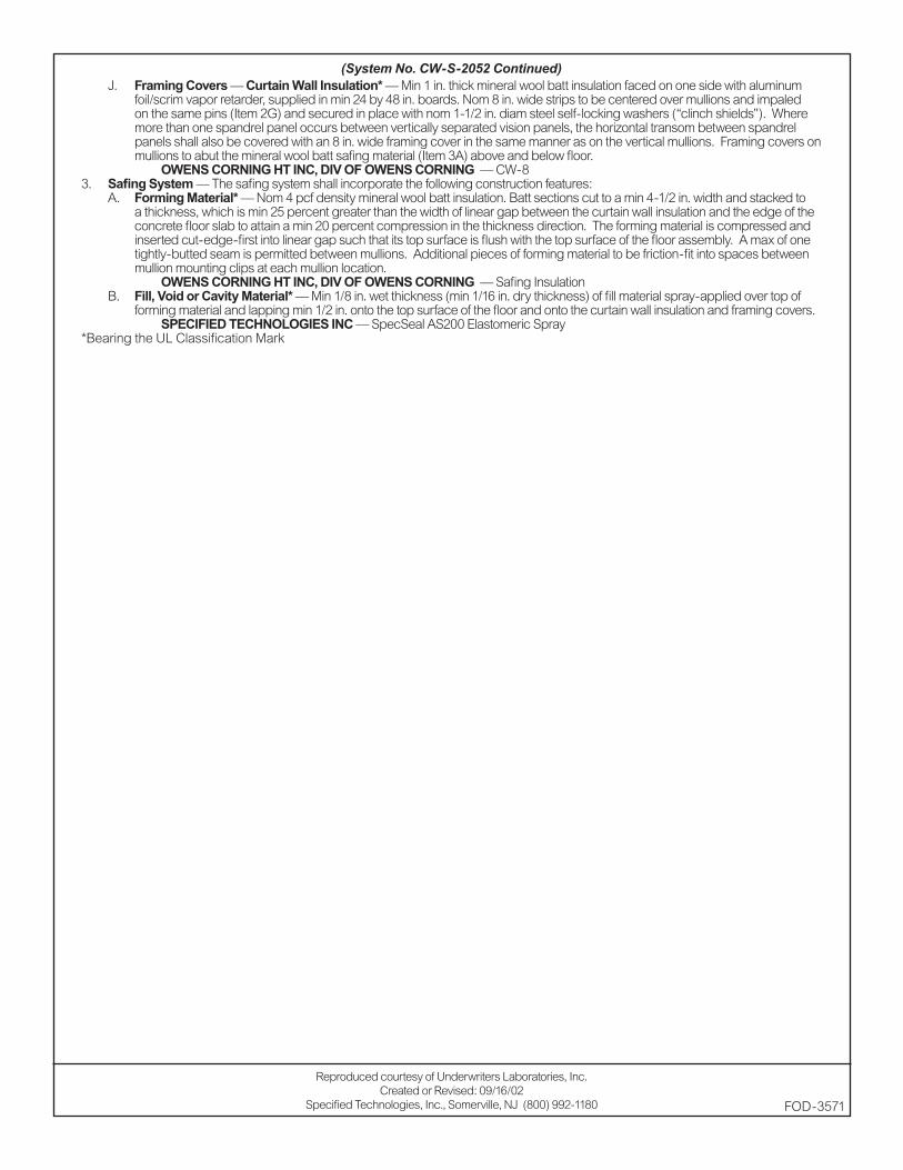
(System No. CW-S-2052 Continued)
Reproduced courtesy of Underwriters Laboratories, Inc.Created or Revised: 09/16/02
Specified Technologies, Inc., Somerville, NJ (800) 992-1180 FOD-3571
J. Framing Covers — Curtain Wall Insulation* — Min 1 in. thick mineral wool batt insulation faced on one side with aluminum foil/scrim vapor retarder, supplied in min 24 by 48 in. boards. Nom 8 in. wide strips to be centered over mullions and impaled on the same pins (Item 2G) and secured in place with nom 1-1/2 in. diam steel self-locking washers (“clinch shields”). Where more than one spandrel panel occurs between vertically separated vision panels, the horizontal transom between spandrel panels shall also be covered with an 8 in. wide framing cover in the same manner as on the vertical mullions. Framing covers on mullions to abut the mineral wool batt safing material (Item 3A) above and below floor.
OWENS CORNING HT INC, DIV OF OWENS CORNING — CW-83. Safing System — The safing system shall incorporate the following construction features:
A. Forming Material* — Nom 4 pcf density mineral wool batt insulation. Batt sections cut to a min 4-1/2 in. width and stacked to a thickness, which is min 25 percent greater than the width of linear gap between the curtain wall insulation and the edge of the concrete floor slab to attain a min 20 percent compression in the thickness direction. The forming material is compressed and inserted cut-edge-first into linear gap such that its top surface is flush with the top surface of the floor assembly. A max of one tightly-butted seam is permitted between mullions. Additional pieces of forming material to be friction-fit into spaces between mullion mounting clips at each mullion location.
OWENS CORNING HT INC, DIV OF OWENS CORNING — Safing InsulationB. Fill, Void or Cavity Material* — Min 1/8 in. wet thickness (min 1/16 in. dry thickness) of fill material spray-applied over top of
forming material and lapping min 1/2 in. onto the top surface of the floor and onto the curtain wall insulation and framing covers. SPECIFIED TECHNOLOGIES INC — SpecSeal AS200 Elastomeric Spray
*Bearing the UL Classification Mark
These products are tested to the following standards where applicable:
ASTM STANDARD:
E 814 Fire Tests of Through-Penetration Fire Stops E 119 Fire Tests of Building Construction and MaterialsE 1966 Fire-Resistive Joint SystemsE 84 Surface Burning Characteristics of Building MaterialsE 1399 Cyclic Movement and Measuring the Minimum and Maximum Joint Widths
of Architectural Joint Systems
UL STANDARD
1479 Fire Tests of Through-Penetration Firestops263 Fire Tests of Building Construction and Materials2079 Tests for Fire-Resistance of Building Joint Systems723 Tests for Surface Burning Characteristics of Building Materials
Chemical Content Statements:
No asbestos, PCB’s or water-soluble intumescent ingredients are used or contained in these products.
_________________________ February1, 2002
James P. Stahl, Jr. DateTechnical Manager
GENERAL CERTIFICATE of CONFORMANCE
Description: SpecSeal Firestop Products
Included Products:
Specifi edTechnologiesInc.
200 Evans Way, Suite 2Somerville, N .J. 08876Phone: (908) 526-8000
Fax: (908) 526-9623Toll Free: (800) 992-1180
Series SSS Intumescent Sealant Series LCI Intumescent SealantSeries LC Latex Endothermic SealantSeries SSP Intumescent Putty Series EP Power Shield™ Box InsertSeries SSWRED Intumescent Wrap StripsSeries SSWBLU Intumescent Wrap StripsSeries SSC Intumescent Firestop CollarsSeries LCC Intumescent Firestop Collars
Series SSB Intumescent Firestop PillowsSeries AS100 Elastomeric SpraySeries AS200 Elastomeric SpraySeries ES100 Elastomeric SealantSeries SSM Firestop MortarPensil Series PEN200 Silicone Foam Pensil Series PEN300 Silicone SealantPensil Series PEN300SL Silicone Sealant
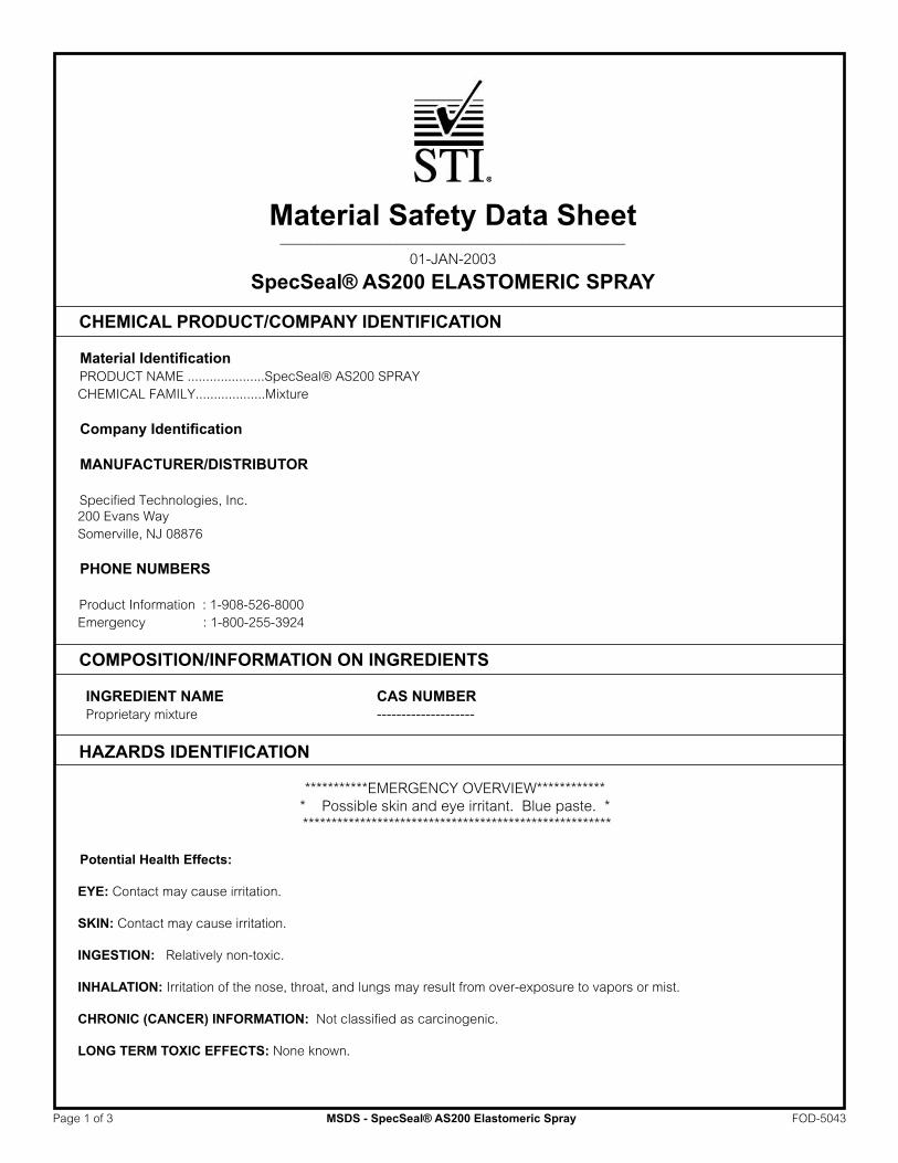
Material Safety Data Sheet _______________________________________________
01-JAN-2003
SpecSeal® AS200 ELASTOMERIC SPRAY
CHEMICAL PRODUCT/COMPANY IDENTIFICATION
Material Identification PRODUCT NAME .....................SpecSeal® AS200 SPRAY CHEMICAL FAMILY...................Mixture
Company Identification
MANUFACTURER/DISTRIBUTOR Specified Technologies, Inc. 200 Evans Way Somerville, NJ 08876
PHONE NUMBERS Product Information : 1-908-526-8000 Emergency : 1-800-255-3924
COMPOSITION/INFORMATION ON INGREDIENTS
INGREDIENT NAME CAS NUMBER Proprietary mixture --------------------
HAZARDS IDENTIFICATION
***********EMERGENCY OVERVIEW************ * Possible skin and eye irritant. Blue paste. * ******************************************************
Potential Health Effects:
EYE: Contact may cause irritation. SKIN: Contact may cause irritation.
INGESTION: Relatively non-toxic.
INHALATION: Irritation of the nose, throat, and lungs may result from over-exposure to vapors or mist.
CHRONIC (CANCER) INFORMATION: Not classified as carcinogenic.
LONG TERM TOXIC EFFECTS: None known.
Page 1 of 3 MSDS - SpecSeal® AS200 Elastomeric Spray FOD-5043
FIRST AID MEASURES First Aid
INHALATION: Remove to fresh air. SKIN CONTACT: Wash thoroughly. EYE CONTACT: Irrigate eyes with running water for at least 15 minutes. Get medical attention if irritation develops. INGESTION: None applicable.
FIRE FIGHTING MEASURES
Not a fire hazard. EXTINGUISHING MEDIA.............................................Dry Chemical; Carbon Dioxide; Foam; Water spray for large fires. SPECIAL FIRE FIGHTING PROCEDURES: .................As for surrounding fire.
ACCIDENTAL RELEASE MEASURES
Safeguards (Personnel) NOTE: Review FIRE FIGHTING MEASURES and HANDLING (PERSONNEL) sections before proceeding with clean-up. Use appropriate PERSONAL PROTECTIVE EQUIPMENT during clean-up.
HANDLING AND STORAGE
Store under ambient conditions. No special handling required.
EXPOSURE CONTROLS/PERSONAL PROTECTION
EYE PROTECTION REQUIREMENTS:.....................Safety glasses/goggles.SKIN PROTECTION REQUIREMENTS:...................Gloves.RESPIRATOR REQUIREMENTS:.............................None.VENTILATION REQUIREMENTS:.............................If needed, use local exhaust ventilation to keep airborne concentrations below the TLV.
Exposure Guidelines Exposure Limits
PEL(OSHA) : Particulates (Not Otherwise Classified) 15 mg/m3, 8 Hr. TWA, total dust 5 mg/m3, 8 Hr. TWA, respirable dust TLV(ACGIH): None Established
PHYSICAL AND CHEMICAL PROPERTIES
PHYSICAL FORM .................................................... Blue paste SPECIFIC GRAVITY................................................. 1.1 PERCENT VOLATILES............................................. 22+/-2 EVAPORATION RATE.............................................. >1 BOILING POINT ...................................................... 100 deg. C SOLUBILITY IN WATER........................................... Infinitely dilutable
STABILITY AND REACTIVITY
STABILITY: .............................................................. This is a stable material. CONDITIONS TO AVOID......................................... Storage >55 deg. C HAZARDOUS POLYMERIZATION:.......................... Will not occur. INCOMPATIBILITIES:……………………………........None special.
TOXICOLOGICAL INFORMATION
Mixture not tested but based on components:
May be irritating to skin and eyes and may produce symptoms of nausea in poorly ventilated areas.
None of the components are listed as carcinogens.
Page 2 of 3 MSDS - SpecSeal® AS200 Elastomeric Spray FOD-5043
ECOLOGICAL INFORMATION
No data.
DISPOSAL CONSIDERATIONS
Waste Disposal: Treatment, storage, transportation, and disposal must be in accordance with applicable Federal, State/Provincial, and Local
regulations.
TRANSPORTATION INFORMATION
DOT – not regulated.
REGULATORY INFORMATION
U.S. Federal Regulations
TSCA Inventory Status : Reported/Included. Section 313 Supplier Notifications. This product contains no toxic chemicals subject to the reporting requirements of Section 313 of the Emergency Planning and
Community Right-To-Know Act of 1986 and of 40 CFR 372:
OTHER INFORMATION
NPCA-HMIS Rating Health : 1 Flammability : 0 Reactivity : 0
Personal Protection rating to be supplied by user depending on use conditions.
STATE RIGHT-TO-KNOW LAWS
No substances on the state hazardous substances list, for the states indicated below, are used in the manufacture of products on this Material Safety Data Sheet, with the exceptions indicated. While we do not specifically analyze these products, or the raw materials used in their manufacture, for substances on various state hazardous substances lists, to the best of our knowledge the products on this Material Safety Data Sheet contain no such substances except for those specifically listed below:
SUBSTANCES ON THE NEW JERSEY WORKPLACE HAZARDOUS SUBSTANCE LIST PRESENT AT A CONCENTRATION OF 1% OR MORE (0.1% FOR SUBSTANCES IDENTIFIED AS CARCINOGENS, MUTAGENS OR TERATOGENS): NJTSRN-AS200 WARNING: SUBSTANCES KNOWN TO THE STATE OF CALIFORNIA TO CAUSE CANCER: None known. WARNING: SUBSTANCES KNOWN TO THE STATE OF CALIFORNIA TO CAUSE BIRTH DEFECTS OR OTHER REPRODUCTIVE HARM: None known.
------------------------------------------------------------------
This information relates to the specific material designated and may not be valid for such material used in combination with any other materials or in any process. Such information is to the best of our knowledge and belief accurate and reliable as of the data compiled. However, no representation, warranty, or guarantee is made as to its accuracy, reliability or completeness. It is the user’s responsibility to satisfy himself as to the suitability and completeness of such information for his own particular use. We do not accept liability for any loss or damage that may occur form the use of this information.
Responsibility for MSDS :
Specified Technologies, Inc.200 Evans WaySomerville, NJ 08876
Page 3 of 3 MSDS - SpecSeal® AS200 Elastomeric Spray FOD-5043
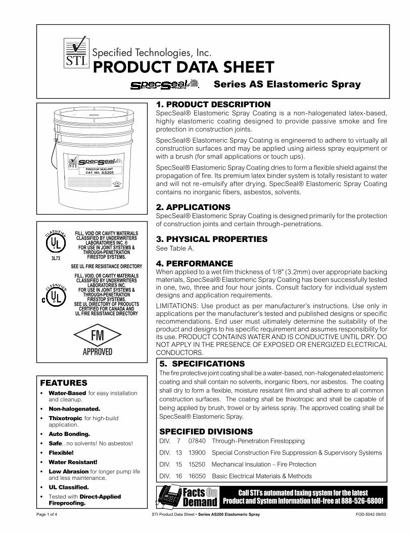
Page 1 of 4 STI Product Data Sheet • Series AS200 Elastomeric Spray FOD-5042 09/03
1. PRODUCT DESCRIPTIONSpecSeal® Elastomeric Spray Coating is a non-halogenated latex-based, highly elastomeric coating designed to provide passive smoke and fi re protection in construction joints.
SpecSeal® Elastomeric Spray Coating is engineered to adhere to virtually all construction surfaces and may be applied using airless spray equipment or with a brush (for small applications or touch ups).
SpecSeal® Elastomeric Spray Coating dries to form a fl exible shield against the propagation of fi re. Its premium latex binder system is totally resistant to water and will not re-emulsify after drying. SpecSeal® Elastomeric Spray Coating contains no inorganic fi bers, asbestos, solvents.
2. APPLICATIONSSpecSeal® Elastomeric Spray Coating is designed primarily for the protection of construction joints and certain through-penetrations.
3. PHYSICAL PROPERTIESSee Table A.
4. PERFORMANCEWhen applied to a wet fi lm thickness of 1/8" (3.2mm) over appropriate backing materials, SpecSeal® Elastomeric Spray Coating has been successfully tested in one, two, three and four hour joints. Consult factory for individual system designs and application requirements.
LIMITATIONS: Use product as per manufacturer’s instructions. Use only in applications per the manufacturer’s tested and published designs or specifi c recommendations. End user must ultimately determine the suitability of the product and designs to his specifi c requirement and assumes responsibility for its use. PRODUCT CONTAINS WATER AND IS CONDUCTIVE UNTIL DRY. DO NOT APPLY IN THE PRESENCE OF EXPOSED OR ENERGIZED ELECTRICAL CONDUCTORS.
5. SPECIFICATIONSThe fi re protective joint coating shall be a water-based, non-halogenated elastomeric coating and shall contain no solvents, in or gan ic fi bers, nor asbestos. The coating shall dry to form a fl exible, moisture re sis tant fi lm and shall adhere to all common construction surfaces. The coating shall be thixotropic and shall be capable of being applied by brush, trowel or by airless spray. The approved coating shall be SpecSeal® Elastomeric Spray.
SPECIFIED DIVISIONSDIV. 7 07840 Through-Penetration Firestopping
DIV. 13 13900 Special Construction Fire Sup pres sion & Supervisory Systems
DIV. 15 15250 Mechanical Insulation – Fire Protection
DIV. 16 16050 Basic Electrical Materials & Methods
FILL, VOID OR CAVITY MATERIALS CLASSIFIED BY UNDERWRITERS
LABORATORIES INC. ® FOR USE IN JOINT SYSTEMS &
THROUGH-PENETRATION FIRESTOP SYSTEMS.
SEE UL FIRE RESISTANCE DIRECTORY
FILL, VOID, OR CAVITY MATERIALS CLASSIFIED BY UNDERWRITERS
LABORATORIES INC. FOR USE IN JOINT SYSTEMS &
THROUGH-PENETRATION FIRESTOP SYSTEMS.
SEE UL DIRECTORY OF PRODUCTS CERTIFIED FOR CANADA AND
UL FIRE RESISTANCE DIRECTORY
3L73
FEATURES• Water-Based for easy installation
and cleanup.
• Non-halogenated.
• Thixotropic for high-build application.
• Auto Bonding. • Safe...no solvents! No asbestos!
• Flexible! • Water Resistant!
• Low Abrasion for longer pump life and less maintenance.
• UL Classifi ed.
• Tested with Direct-Applied Fireproofi ng.
Call STI’s automated faxing system for the latest Product and System Information toll-free at 888-526-6800!
Series AS Elastomeric Spray
PRODUCT DATA SHEET
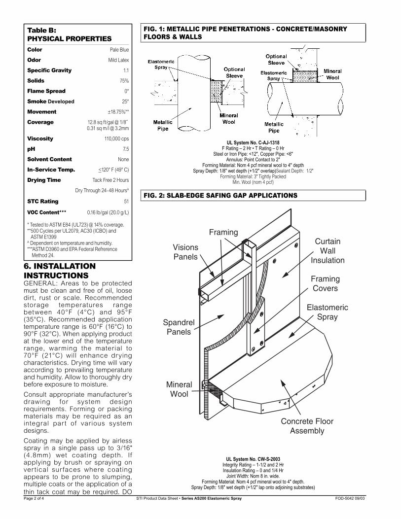
Page 2 of 4 STI Product Data Sheet • Series AS200 Elastomeric Spray FOD-5042 09/03
6. INSTALLATION
INSTRUCTIONSGENERAL: Areas to be protected must be clean and free of oil, loose dirt, rust or scale. Recommended storage temperatures range between 40°F (4°C) and 95°F (35°C). Recommended application temperature range is 60°F (16°C) to 90°F (32°C). When applying product at the lower end of the temperature range, warming the material to 70°F (21°C) will enhance drying characteristics. Drying time will vary according to prevailing temperature and humidity. Allow to thoroughly dry before exposure to moisture.
Consult appropriate manufacturer’s drawing for system design requirements. Forming or packing materials may be required as an integral par t of various system designs.
Coating may be applied by airless spray in a single pass up to 3/16" (4.8mm) wet coating depth. If applying by brush or spraying on ver tical sur faces where coating appears to be prone to slumping, multiple coats or the application of a thin tack coat may be required. DO
Table B: PHYSICAL PROPERTIESColor Pale Blue
Odor Mild Latex
Specifi c Gravity 1.1
Solids 75%
Flame Spread 0*
Smoke Developed 25*
Movement ±18.75%**
Coverage 12.8 sq ft/gal @ 1/8˝ 0.31 sq m/l @ 3.2mm
Viscosity 110,000 cps
pH 7.5
Solvent Content None
In-Service Temp. <120° F (49° C)
Drying Time Tack Free 2 Hours
Dry Through 24-48 HoursA
STC Rating 51
VOC Content*** 0.16 lb/gal (20.0 g/L)
* Tested to ASTM E84 (UL723) @ 14% coverage.**500 Cycles per UL2079, AC30 (ICBO) and ASTM E1399A Dependent on temperature and humidity.***ASTM D3960 and EPA Federal Refrerence
Method 24.
FIG. 1: METALLIC PIPE PENETRATIONS - CONCRETE/MASONRY
FLOORS & WALLS
UL System No. C-AJ-1318F Rating – 2 Hr • T Rating – 0 Hr
Steel or Iron Pipe: <12", Copper Pipe: <6"Annulus: Point Contact to 2"
Forming Material: Nom 4 pcf mineral wool to 4" depthSpray Depth: 1/8" wet depth (+1/2" overlap)Sealant Depth: 1/2"
Forming Material: 3" Tightly Packed Min. Wool (nom 4 pcf)
FIG. 2: SLAB-EDGE SAFING GAP APPLICATIONS
ElastomericSpray
MineralWool
FramingCovers
CurtainWall
Insulation
VisionsPanels
SpandrelPanels
Framing
Concrete FloorAssembly
UL System No. CW-S-2003Integrity Rating – 1-1/2 and 2 HrInsulation Rating – 0 and 1/4 Hr
Joint Width: Nom 8 in. wide.Forming Material: Nom 4 pcf mineral wool to 4" depth.
Spray Depth: 1/8" wet depth (+1/2" lap onto adjoining substrates)
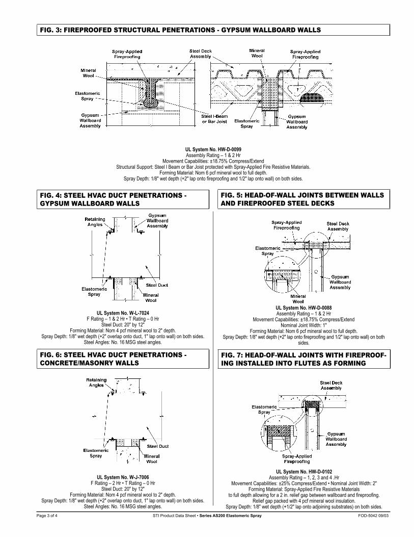
Page 3 of 4 STI Product Data Sheet • Series AS200 Elastomeric Spray FOD-5042 09/03
FIG. 3: FIREPROOFED STRUCTURAL PENETRATIONS - GYPSUM WALLBOARD WALLS
UL System No. HW-D-0099Assembly Rating – 1 & 2 Hr
Movement Capabilities: ±18.75% Compress/ExtendStructural Support: Steel I Beam or Bar Joist protected with Spray-Applied Fire Resistive Materials.
Forming Material: Nom 6 pcf mineral wool to full depth.Spray Depth: 1/8" wet depth (+2" lap onto fi reproofi ng and 1/2" lap onto wall) on both sides.
FIG. 4: STEEL HVAC DUCT PENETRATIONS -
GYPSUM WALLBOARD WALLS
UL System No. W-L-7024F Rating – 1 & 2 Hr • T Rating – 0 Hr
Steel Duct: 20" by 12"Forming Material: Nom 4 pcf mineral wool to 2" depth.
Spray Depth: 1/8" wet depth (+2" overlap onto duct, 1" lap onto wall) on both sides.Steel Angles: No. 16 MSG steel angles.
FIG. 5: HEAD-OF-WALL JOINTS BETWEEN WALLS
AND FIREPROOFED STEEL DECKS
UL System No. HW-D-0088Assembly Rating – 1 & 2 Hr
Movement Capabilities: ±18.75% Compress/ExtendNominal Joint Width: 1"
Forming Material: Nom 6 pcf mineral wool to full depth.Spray Depth: 1/8" wet depth (+2" lap onto fi reproofi ng and 1/2" lap onto wall) on both
sides.
FIG. 6: STEEL HVAC DUCT PENETRATIONS -
CONCRETE/MASONRY WALLS
UL System No. W-J-7006F Rating – 2 Hr • T Rating – 0 Hr
Steel Duct: 20" by 12"Forming Material: Nom 4 pcf mineral wool to 2" depth.
Spray Depth: 1/8" wet depth (+2" overlap onto duct, 1" lap onto wall) on both sides.Steel Angles: No. 16 MSG steel angles.
FIG. 7: HEAD-OF-WALL JOINTS WITH FIREPROOF-
ING INSTALLED INTO FLUTES AS FORMING
UL System No. HW-D-0102Assembly Rating – 1, 2, 3 and 4 .Hr
Movement Capabilities: ±25% Compress/Extend • Nominal Joint Width: 2"Forming Material: Spray-Applied Fire Resistive Materials
to full depth allowing for a 2 in. relief gap between wallboard and fi reproofi ng. Relief gap packed with 4 pcf mineral wool insulation.
Spray Depth: 1/8" wet depth (+1/2" lap onto adjoining substrates) on both sides.
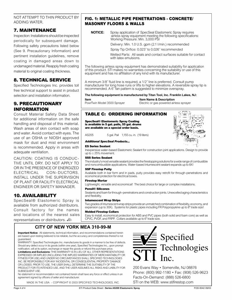
Page 4 of 4 STI Product Data Sheet • Series AS200 Elastomeric Spray FOD-5042 09/03
TABLE C: ORDERING INFORMATION
SpecSeal® Elastomeric Spray Coating is available in 5 gal. pails, 55 gal. drums are available on a special order basis.
AS205 5 gal. Pail 1,155 cu. in. (19 liters)
Additional SpecSeal Products...
ES Series Sealant Inexpensive water-based Elastomeric Sealant for construction joint applications. Design to provide up to ± 25% movement.
SSS Series Sealant The industry's most versatile sealant provides the fi restopping so lu tions for a wide range of com bus ti ble and noncombustible ap pli ca tions. Water-based intumescent sealant expands up to 8X!
SSP Firestop Putty
Available both in bar form and in pads, putty provides easy retrofi t for through-penetrations and eco nom i cal pro tec tion for electrical boxes.
Firestop Mortar Light weight, versatile and economical! The best choice for large or complex installations.
Pensil® Silicones
Sealants and foam for through-penetrations and construction joints. Unexcelled aging characteristics and fl exibility.
Intumescent Wrap Strips
Two grades of intumescent wrap strips provide an unmatched combination of fl exibility, economy, and expansion (up to 30X). Systems for plastic pipes including FR Polypropylene up to 8" trade size!
Molded Firestop Collars
Easy to install, economical protection for ABS and PVC pipes (both solid and foam core) as well as CPVC, PVDF, and FRPP. Collars available up to 6" trade size.
NOT ATTEMPT TO THIN PRODUCT BY ADDING WATER.
7. MAINTENANCE
Inspection: Installations should be inspected periodically for subsequent damage. Following safety precautions listed below (See 9. Precautionary Information) and pertinent installation guidelines, remove coating in damaged areas down to undamaged material. Reapply fresh coating
material to original coating thickness.
8. TECHNICAL SERVICE
Specifi ed Technologies Inc. provides toll free technical support to assist in product selection and installation information.
9. PRECAUTIONARY
INFORMATION
Consult Material Safety Data Sheet for additional information on the safe handling and disposal of this material. Wash areas of skin contact with soap and water. Avoid contact with eyes. The use of an OSHA or NIOSH approved mask for dust and mist environment is recommended. Apply in areas with adequate ventilation.
CAUTION: COATING IS CONDUC-TIVE UNTIL DRY. DO NOT APPLY TO OR IN THE PRESENCE OF EN ER GIZED ELECTRICAL CON - DUCTORS. INSTALL UNDER THE SU PER VI SION OF PLANT OR FA CIL I TY ELECTRICAL ENGINEER OR SAFETY MANAGER.
10. AVAILABILITY
SpecSeal® Elastomeric Spray is available from authorized dis trib u tors. Consult factory for the names and lo ca tions of the nearest sales rep re sen ta tives or distributors.
FIG. 1: METALLIC PIPE PENETRATIONS - CONCRETE/
MASONRY FLOORS & WALLS
NOTICE: Spray application of SpecSeal Elastomeric Spray requires airless spray equipment meeting the following specifi cations:
Working Pressure: Min. 3,000 PSI
Delivery: Min. 1.0 U.S. gpm (2.1 l/min.) recommended
Spray Tip Orifi ce: 0.023˝ to 0.026˝ recommended
Wetted Parts: All seals and contact surfaces suitable for contact with latex emulsions.
The following airless spray equipment has demonstrated suitability for application of this product. STI makes no warranties concerning the suitability or use of this equipment and has no affi liation of any kind with its manufacturer.
A minimum 3/8˝ fl uid line is required, a 1/2˝ line is preferred. Consult pump manufacturer for long hose runs or lifts to higher elevations. A reversible spray tip is recommended. A 6˝ fan pattern is suggested to minimize overspray.
The following equipment is manufactured by Titan Tool, Inc. Franklin Lakes, NJ:
Item Item Name & DescriptionPowrTwin Model 3500 Sprayer Electric or gas powered airless sprayer
CITY OF NEW YORK MEA 310-99-M
Specifi ed Technologies Inc.
Important Notice: All statements, technical information, and recommendations contained herein are based upon testing believed to be reliable, but the accuracy and completeness thereof is not guaranteed.WARRANTY: Specifi ed Technologies Inc. manufactures its goods in a manner to be free of defects. Should any defect occur in its goods (within one year), Specifi ed Technologies Inc., upon prompt notifi cation, will at its option, exchange or repair the goods or refund the purchase price.Limitations and Exclusions: THIS WARRANTY IS IN LIEU OF ALL OTHER REPRESENTATIONS EXPRESSED OR IMPLIED (INCLUDING THE IMPLIED WARRANTIES OF MERCHANTABILITY OR FITNESS FOR USE) AND UNDER NO CIRCUMSTANCES SHALL SPECIFIED TECHNOLOGIES INC. BE RESPONSIBLE FOR ANY INCIDENTAL OR CONSEQUENTIAL PROPERTY DAMAGE OR LOSSES. PRIOR TO USE, THE USER SHALL DETERMINE THE SUITABILITY OF THE PRODUCT FOR ITS INTENDED USE, AND THE USER ASSUMES ALL RISKS AND LIABILITY FOR SUBSEQUENT USE.No statement or recommendation not contained herein shall have any force or effect unless in an agreement signed by offi cers of seller and manufacturer.
200 Evans Way • Somerville, NJ 08876Phone: (800) 992-1180 • Fax: (908) 526-9623Facts-On-Demand: (888) 526-6800STI on the WEB: www.stifi restop.comMADE IN THE USA – COPYRIGHT © 2003 SPECIFIED TECHNOLOGIES, INC.