Submittal Package FTA1100J
12
Publication SBP1100J-60 Rev. B (DRAWINGS INCLUDED IN THIS PACKAGE ARE FOR STANDARD CONTROLLERS. ACTUAL “AS BUILT” DRAWINGS MAY DIFFER FROM THOSE SEEN HERE). Submittal Package MARK III Diesel Engine Fire Pump Controllers FTA1100J While every precaution has been taken to ensure accuracy and completeness herein, Firetrol, Inc. assumes no responsibility, and disclaims all liability, for damages resulting from use of this information or for any errors or omissions. Specifications and drawings are subject to change without notice. ©2019 Firetrol, Inc., All Rights Reserved. 3412 Apex Peakway Apex, North Carolina 27502 P 919 460 5200 F 919 460 5250 www.firetrol.com Project Information
Transcript of Submittal Package FTA1100J
Publication SBP1100J-60 Rev. B
(DRAWINGS INCLUDED IN THIS PACKAGE ARE FOR STANDARDCONTROLLERS. ACTUAL “AS BUILT” DRAWINGS MAY DIFFER
FROM THOSE SEEN HERE).
Submittal Package
MARKIII Diesel Engine Fire Pump Controllers
FTA1100J
While every precaution has been taken to ensure accuracy and completeness herein, Firetrol, Inc. assumes no responsibility, and disclaims all liability, for damages resulting from use of this information or for any errors or omissions. Specifications and drawings are subject to change without notice. ©2019 Firetrol, Inc., All Rights Reserved.
3412 Apex PeakwayApex, North Carolina 27502P 919 460 5200F 919 460 5250www.firetrol.com
Project Information

Firetrol MarkIII Diesel Engine Fire Pump ControllerFTA1100J - 12 or 24 VoltSpecifications
1.0 Main Fire Pump ControllerThe main fire pump controller shall be a factory assembled, wired and tested unit. The controller shall be of the combined manual and automatic type de-signed for diesel engine operation of the fire pump.
1.1 Standards, Listings & ApprovalsThe controller shall conform to all the requirements of the latest editions of:· NFPA 20· UL (UL218 and CSA C22.2 No. 14)· FM Global (Class 1321/1323)· City of New York for fire pump service
1.2 EnclosureThe controller components shall be housed in a NEMA Type 2 (IEC IP22) drip-proof, wall mounted enclosure with bottom entry gland plate.
1.3 Operator Interface (HMI) 7.0” LCD color touch screen (HMI technology) operator interface powered by an
embedded microcomputer with software PLC logic. Included shall be keypad type push-buttons for Crank from Battery #1, Crank from Battery #2, Stop and run test.
The screen shall include menus for: Home · Alarms · Configuration · History · Ser-vice · Manuals · Language.
The HMI shall graphically display the following: AC Power Present · Charger #1 &
#2 Charging Mode · Battery #1 & #2 Voltage and Amperage · System Pressure · Cut In and Cut Out Pressure Settings · Starter #1 and #2 Cranking or Resting · Engine Running · Starting Cause · Fuel Valve Energized · Timers Operation · H-O-A Switch Position · Actuation Mode · Controller Type · Shutdown Mode · Time & Date · Pump Room Temperature · System Pressure
System pressure shall be capable of being displayed as: PSI, kPa, Bar, Feet of Head or Meters of Water.
The HMI shall allow programming and display of: Cut In & Cut Out Pressure Set-tings · Minimum Run Timer · Sequential Start Timer · Periodic Test Timer
The HMI allows the user to select the language of the system and download the manual or view the manual on screen.

1.4 State and Alarm Visual IndicationThe digital display shall visually indicate and color code by criticalness the fol-lowing:AC Fail · DC Fail · Battery 1/2 Fail · Charger 1/2 Fail · Engine Trouble · Pump Room Trouble · Controller Trouble · Service Required · Battery 1/2 Weak · Loss of Con-tinuity with Starting Contactor 1/2 · Weekly Test Start Pressure Not Reached · Weekly Test Check Solenoid Valve · Faulty Pressure Transducer · Low Raw Water Flow · Engine Fail When Running · Engine Fail To Start · Engine Overspeed · Low Ambient Temp. · Pump On Demand · Invalid Cut-In · Overpressure · Underpres-sure · Battery 1/2 Overvoltage · Water Reservoir Low · Fuel Tank Leak · Low Fuel Level · High Fuel Level · Engine ECM In Alternate Position · Engine Fuel Injection Malfunction · Engine High Temperature · Engine Low Temperature · Engine ECM Warning · Engine ECM Fault · Engine Low Oil Pressure · High Raw Water Temper-ature · Low Suction Pressure · Engine Run · Main Switch In Auto · Pump Room Temperature · Periodic Test · Main Switch in Hand · Cranking Cycle · Main Switch In Off · AC Power Available
1.5 Pressure and Event RecordingThe system shall be capable of logging pressure data and operational events with time/date stamp. The system shall display operational events for the life-time of the controller and display the pressure data in text or graphical form. The controller shall log the Date/Time of the first start-up and the controller total power on time from that date. The controller shall log first and last statistics for: First Setup · On Time · Engine On Time · Engine Start Count · Engine Last Start Time · Min/Max/Average System Pressure · Min/Max/Average Pump Room Temp · Jockey Pump On Time · Jockey Pump Start Count · Jockey Pump Last Start Time
1.6 USB Host ControllerA USB port capable of accepting a USB Flash Memory Disk shall be provided for downloading pressure and event logs.
1.7 Serial CommunicationsThe controller shall feature Modbus with TCP/IP frame format and a shielded fe-male RJ45 connector.
1.8 Pressure Sensing / Wet PartsThe controller shall be supplied with a solid state pressure transducer with a range of 0-500 psi calibrated for 0-300 psi (0-20.7 bar) and a run test solenoid valve. The wet parts shall be externally mounted and include a protective cover. The pressure sensing line connection to the transducer shall be 1/2-inch FNPT. Provisions for a redundant pressure transducer shall be provided.
1.9 Seismic CertificationThe controller shall be certified to meet or exceed the requirements of the 2015 International Building Code, the 2016 California Building Code and OSHPD Special Seismic Certification Preapproval - OSP. The controller test criteria shall be per ICC-ES AC156 and the Seismic Parameters per ASCE 7-10 Chapter 13.

2.0 Controller OperationOn a call to start, the controller will crank from battery 1 for 15 seconds then rest for 15 seconds before cranking on battery 2. This cranking cycle shall repeat 3 times. If a running signal is not received from the engine, the controller will alarm “Fail To Start”.The controller shall have the capability to schedule service reminders. The con-troller also provides for inputting of pump flow test data, generating and dis-playing the pump curve and permanently storing this data in memory.Provisions shall be available for connection of external devices for Manual Re-mote Start, Automatic Remote Start and Deluge Valve Start.DPDT dry contacts rated 8A - 250VAC shall be provided for remote indication of: Engine Run · Main Switch in Hand or Off · Controller Trouble (common) · Engine Trouble (common) · Pump Room Trouble (common)An audible alarm device shall be provided on the controller.
2.1 ManufacturerThe controller shall be a Firetrol brand.
Publication SP1100-60
3412 Apex PeakwayApex, North Carolina 27502P +1 919 460 5200F +1 919 460 5250www.firetrol.comWhile every precaution has been taken to ensure accuracy and completeness herein, Firetrol, Inc. assumes no responsibility, and disclaims all liability, for damages result-ing from use of this information or for any errors or omissions. Specifications and drawings are subject to change without notice. ©2019 Firetrol, Inc., All Rights Reserved.
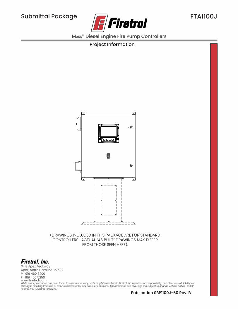
Description – Firetrol® combined automatic and manual MarkIII based diesel engine fire pump controllers are intended for starting and monitor-ing fire pump diesel engines. They are suitable for use with both mechanical and electronic type engines. The controller is available for 12 or 24 volt negative ground systems, using lead acid or Nickel-Cadmium batteries. The controller monitors, displays and records fire pump system information.Approvals – Firetrol fire pump controllers are listed by Underwriters’ Laboratories, Inc., in ac-cordance with UL218, Standard for Fire Pump Controllers, CSA, Standard for Industrial Control Equipment (cUL), and approved by Factory Mutual. They are built to meet or exceed the requirements of the approving authorities as well as NEMA and the latest editions of NFPA 20, Installation of Centrifugal Fire Pumps, and NFPA 70, National Electrical Code.Standard Features – The following are included as standard with each controller:• NEMA Type 2 (IP22) Enclosure with Bottom En-
try Gland Plate, Lifting Lugs and Locking Door Handle
• AC Line & Battery circuit breakers• Two independent battery chargers, 10A continuous
charge - 500mA Trickle Charge• 7.0” LCD color touch screen (HMI technology)
software upgradeable operator interface powered by an embedded microcomputer with software PLC logic.
• Push-buttons for Crank from Battery #1, Crank from Battery #2, Stop and Run Test
• 500 PSI Pressure Transducer (calibrated for 300 PSI (20.7 Bar) and Test Solenoid for fresh water applications, externally mounted with protective cover
• Audible Alarm Bell• Pressure and Event Recording with Date Stamp
to System Memory Accessible VIA The User In-terface and Downloadable to a USB Flash Drive
• Visual Indication for: Engine Run • Main Switch Position • Periodic Test • Cranking Cycle • AC Power Available • Pump Room Temperature
• Visual Alarm Indication for: Pump Room Trouble • Pump On Demand • AC Power Failure • Char-ger 1-2 Failure • Battery 1-2 Weak • Battery 1-2 Overvoltage • Loss of Continuity on Starter 1-2 • High Fuel Level • Fuel Tank Leak • PLD Low Suction Pressure • High Raw Water Temp. • Low Pump Room Temp. • High Pump Room Temp. • ECM Warning • Weekly Test Cut-In Pressure Not Reached • Check Weekly Test Solenoid • Pres-sure Transducer Fault • Invalid Cut-In Pressure • Service Required
• Audible and Visible Alarm Indication for: En-gine Trouble • Controller Trouble • Engine Low Oil Pressure • Engine High Temp. • Engine Low Temp. • Engine Overspeed • DC Failure • Battery 1-2 Failure • Engine Fail To Start • Low Fuel Level • ECM Fault • ECM SS In Alternate Position • Fuel Injection Malfunction
• DPDT 8A 250V Remote Alarm Contacts Are Provided For:
• Engine Run • Common Controller Trouble (Charger Failure, Pressure Transducer Fault) • Common Engine Trouble (High Engine
Temp., Fail To Start, Fuel Injection Malfunction, ECM Selector Switch in Alternate Position, Battery 1-2 Failure, DC Failure, Loss of Continuity to Starter 1-2, Engine Overspeed, Fail When Running, Low Oil Pressure, PLD Low Suction Pressure) • Common Pump Room Trouble (Low Fuel Level, High Fuel Level, Fuel Tank Leak, Low / High Pump Room Temperature, AC Power Failure, H-O-A Selector Switch in OFF or HAND)• Modbus Communications with TCP/IP frame
format and a shielded female RJ45 connector.• Input Terminals for Connection to External De-
vices: • Low Fuel Level • Remote AUTOMATIC Start • Deluge Valve Start (re-assignable) • Fuel Tank Leak (re-assignable) • High Fuel Level (re-assignable)• Pump Room Ambient Temperature Switch, Dis-
play and Alarms• Seismic Certification per IBC 2015, CBC 2016
MarkIII Diesel Engine Fire Pump Controller
Product Description
FTA1100J
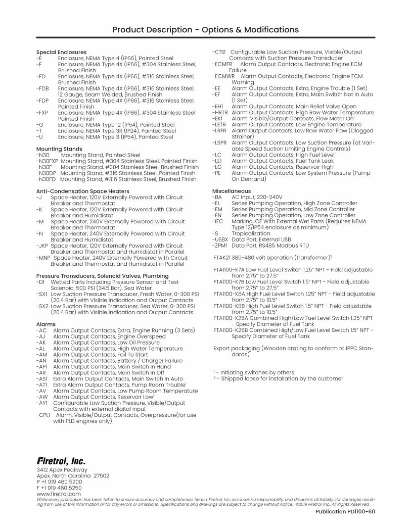
Special Enclosures-E Enclosure, NEMA Type 4 (IP66), Painted Steel-F Enclosure, NEMA Type 4X (IP66), #304 Stainless Steel, Brushed Finish-FD Enclosure, NEMA Type 4X (IP66), #316 Stainless Steel, Brushed Finish-FDB Enclosure, NEMA Type 4X (IP66), #316 Stainless Steel, 12 Gauge, Seam Welded, Brushed Finish-FDP Enclosure, NEMA Type 4X (IP66), #316 Stainless Steel, Painted Finish-FXP Enclosure, NEMA Type 4X (IP66), #304 Stainless Steel Painted Finish-G Enclosure, NEMA Type 12 (IP54), Painted Steel-T Enclosure, NEMA Type 3R (IP24), Painted Steel-U Enclosure, NEMA Type 3 (IP54), Painted Steel
Mounting Stands-N30 Mounting Stand, Painted Steel-N30FXP Mounting Stand, #304 Stainless Steel, Painted Finish-N30F Mounting Stand, #304 Stainless Steel, Brushed Finish-N30DP Mounting Stand, #316 Stainless Steel, Painted Finish-N30FD Mounting Stand, #316 Stainless Steel, Brushed Finish
Anti-Condensation Space Heaters-J Space Heater, 120V Externally Powered with Circuit
Breaker and Thermostat-K Space Heater, 120V Externally Powered with Circuit
Breaker and Humidistat-M Space Heater, 240V Externally Powered with Circuit
Breaker and Thermostat-N Space Heater, 240V Externally Powered with Circuit
Breaker and Humidistat-JKP Space Heater, 120V Externally Powered with Circuit
Breaker and Thermostat and Humidistat in Parallel-MNP Space Heater, 240V Externally Powered with Circuit
Breaker and Thermostat and Humidistat in Parallel
Pressure Transducers, Solenoid Valves, Plumbing-D1 Wetted Parts Including Pressure Sensor and Test Solenoid, 500 PSI (34.5 Bar), Sea Water-SX1 Low Suction Pressure Transducer, Fresh Water, 0-300 PSI
(20.4 Bar) with Visible Indication and Output Contacts-SX2 Low Suction Pressure Transducer, Sea Water, 0-300 PSI
(20.4 Bar) with Visible Indication and Output Contacts
Alarms-AC Alarm Output Contacts, Extra, Engine Running (3 Sets)-AJ Alarm Output Contacts, Engine Overspeed-AK Alarm Output Contacts, Low Oil Pressure-AL Alarm Output Contacts, High Water Temperature-AM Alarm Output Contacts, Fail To Start-AN Alarm Output Contacts, Battery / Charger Failure-AP1 Alarm Output Contacts, Main Switch In Hand-AR Alarm Output Contacts, Main Switch In Off-AS1 Extra Alarm Output Contacts, Main Switch In Auto-AT1 Extra Alarm Output Contacts, Pump Room Trouble1
-AV Alarm Output Contacts, Low Pump Room Temperature -AW Alarm Output Contacts, Reservoir Low1 -AY1 Configurable Low Suction Pressure, Visible/Output
Contacts with external digital input-CPL1 Alarm, Visible/Output Contacts, Overpressure(for use
with PLD engines only)
-CTS1 Configurable Low Suction Pressure, Visible/Output Contacts with Suction Pressure Transducer
-ECMFR Alarm Output Contacts, Electronic Engine ECM Failure
-ECMWR Alarm Output Contacts, Electronic Engine ECM Warning
-EE Alarm Output Contacts, Extra, Engine Trouble (1 Set)-EF Alarm Output Contacts, Extra, Main Switch Not In Auto
(1 Set)-EH1 Alarm Output Contacts, Main Relief Valve Open-HRTR Alarm Output Contacts, High Raw Water Temperature-EK1 Alarm, Visible/Output Contacts, Flow Meter On1
-LETR Alarm Output Contacts, Low Engine Temperature-LRFR Alarm Output Contacts, Low Raw Water Flow (Clogged
Strainer)-LSPR Alarm Output Contacts, Low Suction Pressure (at Vari-
able Speed Suction Limiting Engine Controls)-LC Alarm Output Contacts, High Fuel Level1 -LE1 Alarm Output Contacts, Fuel Tank Leak-LG Alarm Output Contacts, Reservoir High1 -PE Alarm Output Contacts, Low System Pressure (Pump
On Demand)
Miscellaneous-BA AC Input, 220-240V-EL Series Pumping Operation, High Zone Controller-EM Series Pumping Operation, Mid Zone Controller-EN Series Pumping Operation, Low Zone Controller-IEC Marking, CE With External Wet Parts (Requires NEMA
Type 12/IP54 enclosure as minimum)-S Tropicalization-USBX Data Port, External USB-ZPM1 Data Port, RS485 Modbus RTU
FTAK21 380-480 volt operation (transformer)2
FTA1100-K7A Low Fuel Level Switch 1.25” NPT - Field adjustable from 2.75” to 27.5”
FTA1100-K7B Low Fuel Level Switch 1.5” NPT - Field adjustable from 2.75” to 27.5”
FTA1100-K8A High Fuel Level Switch 1.25” NPT - Field adjustable from 2.75” to 10.5”
FTA1100-K8B High Fuel Level Switch 1.5” NPT - Field adjustable from 2.75” to 10.5”
FTA1100-K26A Combined High/Low Fuel Level Switch 1.25” NPT - Specify Diameter of Fuel Tank
FTA1100-K26B Combined High/Low Fuel Level Switch 1.5” NPT - Specify Diameter of Fuel Tank
Export packaging (Wooden crating to conform to IPPC Stan-dards)
1 - Initiating switches by others2 - Shipped loose for installation by the customer
Product Description - Options & Modifications
Publication PD1100-60
3412 Apex PeakwayApex, North Carolina 27502P +1 919 460 5200F +1 919 460 5250www.firetrol.comWhile every precaution has been taken to ensure accuracy and completeness herein, Firetrol, Inc. assumes no responsibility, and disclaims all liability, for damages result-ing from use of this information or for any errors or omissions. Specifications and drawings are subject to change without notice. ©2019 Firetrol, Inc., All Rights Reserved.

FTA1100-J _ __ N- __ (Example: FTA1100-JL24N-G-AM)
Controller Type J - MarkIII
Battery Type L - Lead Acid N - Ni-Cad
Battery Voltage 12 - 12 Volt DC 24 - 24 Volt DC System Ground N - Negative Ground
Special Enclosures-E Enclosure, NEMA Type 4 (IP66), Painted Steel-F Enclosure, NEMA Type 4X (IP66), #304 Stainless
Steel, Brushed Finish-FD Enclosure, NEMA Type 4X (IP66), #316 Stainless
Steel, Brushed Finish-FDB Enclosure, NEMA Type 4X (IP66), #316 Stainless
Steel, 12 Gauge, Seam Welded, Brushed Finish-FDP Enclosure, NEMA Type 4X (IP66), #316 Stainless
Steel, Painted Finish-FXP Enclosure, NEMA Type 4X (IP66), #304 Stainless
Steel, Painted Finish-G Enclosure, NEMA Type 12 (IP54), Painted Steel-T Enclosure, NEMA Type 3R (IP24), Painted Steel-U Enclosure, NEMA Type 3 (IP54), Painted Steel
Mounting Stands-N30 Mounting Stand, Painted Steel-N30FXP Mounting Stand, #304 Stainless Steel, Painted
Finish-N30F Mounting Stand, #304 Stainless Steel, Brushed
Finish-N30DP Mounting Stand, #316 Stainless Steel, Painted
Finish-N30FD Mounting Stand, #316 Stainless Steel, Brushed
Finish
Options and Modifications
Anti-Condensation Space Heaters-J Space Heater, 120V Externally Powered with
Circuit Breaker and Thermostat-K Space Heater, 120V Externally Powered with
Circuit Breaker and Humidistat-M Space Heater, 240V Externally Powered with
Circuit Breaker and Thermostat-N Space Heater, 240V Externally Powered with
Circuit Breaker and Humidistat-JKP Space Heater, 120V Externally Powered with
Circuit Breaker and Thermostat and Humidistat in Parallel
-MNP Space Heater, 240V Externally Powered with Circuit Breaker and Thermostat and Humidistat in Parallel
Pressure Transducers, Solenoid Valves, Plumbing
-D1 Wetted Parts Including Pressure Sensor and Test Solenoid, 500 PSI (34.5 Bar), Sea Water
-SX1 Low Suction Pressure Transducer, Fresh Water, 0-300 PSI (20.4 Bar) with Visible Indication and Output Contacts
-SX2 Low Suction Pressure Transducer, Sea Water, 0-300 PSI (20.4 Bar) with Visible Indication and Output Contacts
Continued on other side
MarkIII Diesel Engine Fire Pump Controller
Model NumberSelection Guide
FTA1100J
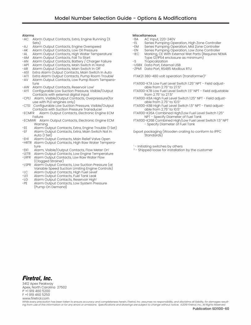
Alarms-AC Alarm Output Contacts, Extra, Engine Running (3
Sets)-AJ Alarm Output Contacts, Engine Overspeed-AK Alarm Output Contacts, Low Oil Pressure-AL Alarm Output Contacts, High Water Temperature-AM Alarm Output Contacts, Fail To Start-AN Alarm Output Contacts, Battery / Charger Failure-AP1 Alarm Output Contacts, Main Switch In Hand-AR Alarm Output Contacts, Main Switch In Off-AS1 Extra Alarm Output Contacts, Main Switch In Auto-AT1 Extra Alarm Output Contacts, Pump Room Trouble1
-AV Alarm Output Contacts, Low Pump Room Tempera-ture
-AW Alarm Output Contacts, Reservoir Low1 -AY1 Configurable Low Suction Pressure, Visible/Output
Contacts with external digital input-CPL1 Alarm, Visible/Output Contacts, Overpressure(for
use with PLD engines only)-CTS1 Configurable Low Suction Pressure, Visible/Output
Contacts with Suction Pressure Transducer-ECMFR Alarm Output Contacts, Electronic Engine ECM
Failure-ECMWR Alarm Output Contacts, Electronic Engine ECM
Warning-EE Alarm Output Contacts, Extra, Engine Trouble (1 Set)-EF Alarm Output Contacts, Extra, Main Switch Not In
Auto (1 Set)-EH1 Alarm Output Contacts, Main Relief Valve Open-HRTR Alarm Output Contacts, High Raw Water Tempera-
ture-EK1 Alarm, Visible/Output Contacts, Flow Meter On1
-LETR Alarm Output Contacts, Low Engine Temperature-LRFR Alarm Output Contacts, Low Raw Water Flow
(Clogged Strainer)-LSPR Alarm Output Contacts, Low Suction Pressure (at
Variable Speed Suction Limiting Engine Controls)-LC Alarm Output Contacts, High Fuel Level1 -LE1 Alarm Output Contacts, Fuel Tank Leak-LG Alarm Output Contacts, Reservoir High1 -PE Alarm Output Contacts, Low System Pressure
(Pump On Demand)
Miscellaneous-BA AC Input, 220-240V-EL Series Pumping Operation, High Zone Controller-EM Series Pumping Operation, Mid Zone Controller-EN Series Pumping Operation, Low Zone Controller-IEC Marking, CE With External Wet Parts (Requires NEMA
Type 12/IP54 enclosure as minimum)-S Tropicalization-USBX Data Port, External USB-ZPM1 Data Port, RS485 Modbus RTU
FTAK21 380-480 volt operation (transformer)2
FTA1100-K7A Low Fuel Level Switch 1.25” NPT - Field adjust-able from 2.75” to 27.5”
FTA1100-K7B Low Fuel Level Switch 1.5” NPT - Field adjustable from 2.75” to 27.5”
FTA1100-K8A High Fuel Level Switch 1.25” NPT - Field adjust-able from 2.75” to 10.5”
FTA1100-K8B High Fuel Level Switch 1.5” NPT - Field adjust-able from 2.75” to 10.5”
FTA1100-K26A Combined High/Low Fuel Level Switch 1.25” NPT - Specify Diameter of Fuel Tank
FTA1100-K26B Combined High/Low Fuel Level Switch 1.5” NPT - Specify Diameter of Fuel Tank
Export packaging (Wooden crating to conform to IPPC Standards)
1 - Initiating switches by others2 - Shipped loose for installation by the customer
Model Number Selection Guide - Options & Modifications
Publication SD1100-60
3412 Apex PeakwayApex, North Carolina 27502P +1 919 460 5200F +1 919 460 5250www.firetrol.comWhile every precaution has been taken to ensure accuracy and completeness herein, Firetrol, Inc. assumes no responsibility, and disclaims all liability, for damages result-ing from use of this information or for any errors or omissions. Specifications and drawings are subject to change without notice. ©2019 Firetrol, Inc., All Rights Reserved.

Dimensions andShipping Weight
MARKIII Diesel Engine Fire Pump Controller
FTA1100J
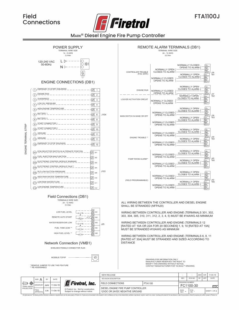
FieldConnections
MARKIII Diesel Engine Fire Pump Controller
FTA1100J

FieldConnections
MARKIII Diesel Engine Fire Pump Controller
FTA1100J

WiringSchematic
MARKIII Diesel Engine Fire Pump Controller
FTA1100J