FINAL OPGW PRESENT1 - Supreme & Co Pvt. Ltd. · PDF file5 IMPORTANT CONSIDERATIONS FOR...
30
1
Transcript of FINAL OPGW PRESENT1 - Supreme & Co Pvt. Ltd. · PDF file5 IMPORTANT CONSIDERATIONS FOR...

1

2
OPTICAL FIBERS
An optical fiber is a glass or plastic fiber that carries light along its length without much attenuation or loss.
The glass used to make Optical Fibers is pure.
The repeater distances on long haul routes for optical fibers varies from 50 to 150 km.

3
Why Optical Fibers ?
In today’s world where the spectrum of signals being communicated (viz. voice data, graphics, video, images etc.) is increasing continuously as also the fact that communication need is getting more & more real-time, bandwidth of the communication medium is becoming more and more critical.
Earlier copper wires were used for telephonic and telegraphic communication. But soon demand increased, beyond the capacity and capability of copper wires as the data transport got added to voice communication. Then came coaxial copper cables, VHF and UHF Radios, Satellite but demand still outstripped the supply.
Then optical Fibers enables large amount of communication bandwidth economically and easily available to everyone.
For example 50,000 voice / data circuit copper cable is massive in size and very expensive, while a single Optical Fiber, the diameter of human hair, can carry 5,00,000 circuits of voice and data. This capacity is increasing day by day as supporting electronics is developing. In itself the capacity of Optical Fibers is limitless.

4
IMPORTANT CONSIDERATIONS FOR RETROFITTING OF OPGW & ADSS ON POWER LINE
• Where durability is very important consideration, OPGW is the most common type of overhead fiber optic cable as it has the longest life expectancy of any fibre optic type cable
• The proportion of aluminum alloy and aluminium clad wires are designed to achieve required tensile strength and sag characteristics as well as conduction of fault currents and lightning currents without damage.
• ADSS is more commonly used to retrofit communication capability to a line where de-energisation of power line is not feasible.
• However, ease of live line installation of ADSS is to be balanced by two important considerations as –
• Possibility of ADSS cable sheath damage due to exposure to electric field
• Lower life expectancy of ADSS vis-a-vis OPGW
• Maximum voltage for optical wires in phase conductors should be limited to 132 kV. In this type of cable, a critical design aspect is transition from line voltage to ground these cables are susceptible to failure due to uncontrolled electrical field gradient and dry band arcing resulting from build-up of particulate pollution.
• Fiber optic cable sag should co-ordinated with the phase conductor sag to prevent mid span flash-over.
• Maximum rated design tension should ensure that zero strain limit of optical fibres in not exceeded.
• Suitable vibration damping to damp aeolin vibrations and to reduce galloping motion so that motions are kept within acceptable limits.

5
IMPORTANT CONSIDERATIONS FOR RETROFITTING OF OPGW & ADSS ON POWER LINE
• Optical fibers are vulnerable to attenuation due to mechanical strain and moisture. Design of the cable has to factor in the required safeguards to avoid mechanical strain and moisture.
• Environmental consideration like corrosion sensivity of a location; wind and ice loads on cable are factors to be considered in design.
• Factors that may influence the interaction of the hardware with cable interface are as follows:
• Excessive contact pressure by clamping hardware may cause the maximum acceptable crushing limits of the cable to be exceeded.
• Contact between dissimilar materials may cause excessive corrosion in some environments. It is therefore recommended that hardware and other accessories connected electrically and mechanically to the cable are compatible for the cable being used.
• Corona from the tips of armor rods can erode that sheath of ADSS. If the ends of the armor rods are not aligned so that they all terminate at the same location along the cable length, then the sheath can be burnt by corona at protruding armor rod tips.

6
IMPORTANT CONSIDERATIONS FOR RETROFITTING OF OPGW & ADSS ON POWER LINE
• Wind loading on long spans may cause tension augmentattion in OPGW and ADSS beyond acceptable limits. It is advisable to have special cable for long span application to ensure
that cable is able withstand higher tensile stresses as also ensure zero optical fiber strain.
• While retrofitting OPGW, to ensure electrical and mechanical matching of ground wire and OPGW
should have similar diameters and aluminum to steel ratios.
• Pole strength should be checked while retrofitting ADSS to ensure that poles have adequate strength to meet additional loads.

7
WORKING OF OPTICAL FIBERS
Fiber optic cable functions as a "light guide," guiding the light introduced at one end of the cable through to the other end. The light source can either be a light-emitting diode (LED)) or a laser. The light source is pulsed on and off at the transmitting (TX) end, and a light-sensitive receiver (Rx) on the other end of the cable converts the pulses back into the digital ones and zeros of the original signal.
Basic Transmission System
OPTICAL FIBER CABLE

8
ADVANTAGES OF OPTICAL FIBERS
Very High Data Transmission Capability.Low Attenuation (Levels<0.2 Db/Km)Small In Diameter And Light WeightLow Cost As Compared To Copper Greater Safety And Immunity From Emi & Rfi, Moisture & CorrosionFlexible And Easy To Install In Tight Conduits & DuctsZERO RESALE VALUE (So Theft Is Less)It Is Dielectric In Nature So Can Be Laid In Electrically Sensitive SurroundingsDifficult To Tap Fibers, So SecureNo Cross Talk And Disturbances

9
LIMITATION IN USING OF OPTICAL FIBERS…
Fiber optic cable connectors and the equipment needed to install and test them are still more expensive than their copper counterparts.Optical Fiber require a careful handling.Communication is not totally in optical domain, so electrical to light energy conversion and vice versa device is needed.Tapping is not easy. Specialized equipment is needed to tap a fiber.Optical fiber splicing is a specialized technique and needs expertly trained manpower.

10
Characteristics ofOptical Fiber
Advantage of Optical Fiber
Thin Diameter
Light Weight
Easy Bending
Noise Immunity
Low Loss
Wide Bandwidth
Space Use
Easy Multi-Fiber Cabling
Easy Installation
Interference
Long Repeatless Range
Large Capacity Transmission Line

11
APPLICATIONS OF OPTICAL FIBERS…
LONG DISTANCE COMMUNICATION BACKBONE
INTER-EXCHANGE JUNCTIONS
VIDEO TRANSMISSION
BROADBAND SERVICES
COMPUTER DATA COMMUNICATION (LAN, WAN, MAN etc.)
HIGH EMI AREAS
MILITARY APPLICATION
NON-COMMUNICATION APPLICATIONS (sensors, fiber lasers etc.)
PROTECTION OF PHASE CONDUCTORS FROM LIGHTNING STRIKES AND TO LIMIT FAULT CURRENT
COMMUNICATION MEDIUM FOR SCADA NETWORKS

12
COMPARISON WITH OTHER MEDIA / TECHNOLOGIES
40-45 kms1/3rd GlobeAbout 40 Kms4km for L/T 2km for S/T
Repeater Spacing for wide band system
9
Not requiredNot required Not requiredMaximum protection arrangement have to be made
Effect of Electro magnetic and electrostatic induction
8
Easier than that of coaxial cables
Least Lesser More time consuming specially in difficult terrain
Time for completion 7
Cheapest for higher no of channels
Costlier than CXL system
CheaperVery CostlyCost6
one pair can be marked for this purpose
Wide coverageLimited use to droop/ insert sub-base band facilities
Very easily possible to drop/ insert channels on main system or use interstice system
Links for wayside stations
5
BER* (Bit error ratio) is very satisfactory (upto10)
Same as for M/WNoise/ km is higher Upto less than 1 PW/ kmNoise performance 4
On the pair system of 1 GB/s system feasible now (About 20,000 channel)
1332 Channels/ transponder
Maximum of 1800 channels in analogue version and 1920 channels digital version per RF channel possible
Upto 10,800 channels (60MHz) per pare of cable core
Capacity3
Most reliableStringent maintenance for reliability
Frequent maintenance requirement
Highly reliableReliability of data Network
2
SimpleDetailDetailSimpleEngg. system required1
Optical FiberSatellite MicrowaveCoaxialParticularSl.No.
*BER (Bit Error Ratio) : It is the ratio of the number of bits, elements, characters or blocks incorrectly received to the total no of bits, elements, characters or blocks sent during the specified time internal.

13
VARIOUS TYPES OF OPTICAL FIBER CABLES
OPGW Cable
ADSS type Optical Fiber Cable
Self-Support AERIAL Cable
OFPC : OPTICAL FIBRE PHASE CABLE
LASHED type Optical Fiber Cable
UNDERGROUND / BURIED type of Cables
DUCT Type Optical Fiber Cable

14
Type of Aerial Fiber Optics

15
WHAT ? Optical fiber ground wire
WHERE?1.On transmission lines at the top of the towers2. On new transmission lines or existing lines
FUNCTIONS :-OPGW can perform both the function of ground wire and telecommunication.
PROPERTIES :-1. It can be designed to achieve the desired tensile strength and sag characteristics.2. It can also be used for conducting fault currents and lightning
currents without damage.
OPGW

16
Optical fiber parameter andperformance

17
Specimen specification of OPGW & OPUG
BlackPE sheath, color:
-200C to 800CRated temperature:
……….Layer-stranded:
<3.5 ps /nm x km at 1310 nm<18 ps /nm x km at 1550 nm
Parameter of dispersion:
<0.35 dB/km at 1310 nm<0.25 dB/km at 1550 nm
Attenuation coefficient
1250 nm, following ITU-T G.652Cut-off wavelength:
Less than 2%Cladding non-circularity:
Less than 6%Mode field non-circularity:
Less than 0.7 µmConcentricity error:
125 µm, ±2Sheath( cladding ) diameter:
8 to 9.5 µm at 1310 nm9 to 11.5 µm at 1550 nm
Mode field diameter:
18
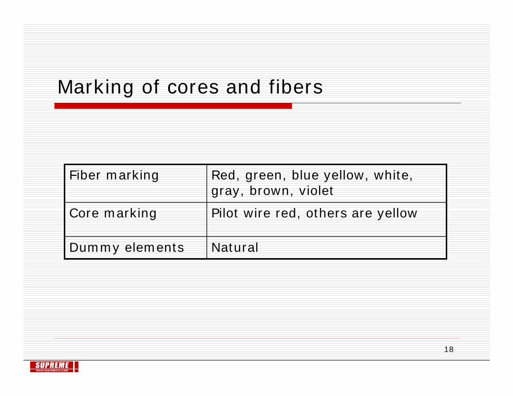
Marking of cores and fibers
NaturalDummy elements
Pilot wire red, others are yellowCore marking
Red, green, blue yellow, white, gray, brown, violet
Fiber marking

19
Fiber coatingThe optical fiber are coated with tight outer UV-hardened acrylate (type of polymer) protective coating; diameter 250µm + 15µm.
Coatings are mechanically easily removable over a length up to 50 mm for the purpose of cleaning.To reduce losses optical fibers are not to generate H2 gas.All coatings/colors are compatible with fusion splicers utilizing the light inject detect (LID).
Acrylate : an acrylate is a type of polymer which could be refined as plastics generally, they are used for their transparency and resistance to breakage and elasticity

20
Color coding of optical fibers
Each fiber color coded in order to identify as specify in IEC 60304.Color coding are not degrade the optical cladding/core either mechanically or optically.It also helps to identify all optical fibers within each coded loose tube.The colors are permanent.

21
Aerial Fiber Optic Cables : Accessories required for different cable type & application
Wedge dead ends and articulated suspensions.Helical Deadends and suspension.
ADSS cables (dielectric)Distribution line
Helical dead ends and suspension sets, vibration damper, Downlead clamps for towers.
ADSS cables (dielectric)Transmission line
Helical dead ends and suspension sets, vibration damper, OPGW Downlead clamps for towers.
OPGWTransmission line
ProductsCable TypeApplication

22
OPGW INSTALLATION

23
Overhead OPGW installation
This Image is received courtesy TG Group and any further reproduction may only be done with permission

24
DIFFERENT OPGW CONSTRUCTIONS
This Image is received courtesy TG Group and any further reproduction may only be done with permission
Optical Fibre & Gel
FRP
Loose Tube
Thermal Barrier
Al-tube
As Wire (23% IACS)

25
Mechanical Suspensions - Single & Double

26
Sheath Stripper:
The Fiber Optic Sheath Stripper is designed to longitudinally score the tight structure fiber units within certain OPGW designs. A simple pull of the Sheath Stripper along the fiber unit ensures correct score depth allowing for easy removal of the overall unit sheath and access to the enclosed fibers.

27
Splice Enclosure1. OPGW splice enclosure installs quickly and easily, without tapes or adhesives.2. It provides protection for spliced fibers.

28
OPGW

29
With Helical Wires
Helical wire arrangement shown below is the preferred option and recommended to customers by Supreme. This arrangement results in low unit compression stresses as total compression stress are distributed over long length. This system is ideal to prevent damage to sensitive fibers. In case of bolted type clamps, fiber may get damaged by concentrated clamping stresses.
With Multi Bolts Clamp
DEAD-ENDING OF OPGW

30
• Can be dismantled• Easy and quick installation• Possible visual control of installation• Savings on cables and jointing boxes• Long experience on this technology• Process and testing technology• No special training tools required• This option is being offered by Supreme at present
• Can be dismantled• Easy and quick installation
• Limited mechanical withstand• High production investment
• Guaranteed mechanical withstand • Cannot be dismantled• Long installation time• Critical installation method• Specific tooling required (group-jack)• Highly qualified staff
• Can be dismantled• Easy and quick installation
• Strain on the external layer wire• High production investment• Specific tooling required(dynamometric spanner)• Visual control is not possible after installation
Advantages DrawbacksDead-end Technology
DEAD-ENDING OF OPGW