Supply Chain-Target vs Kmart- Final 4.15-Final Final Final Final
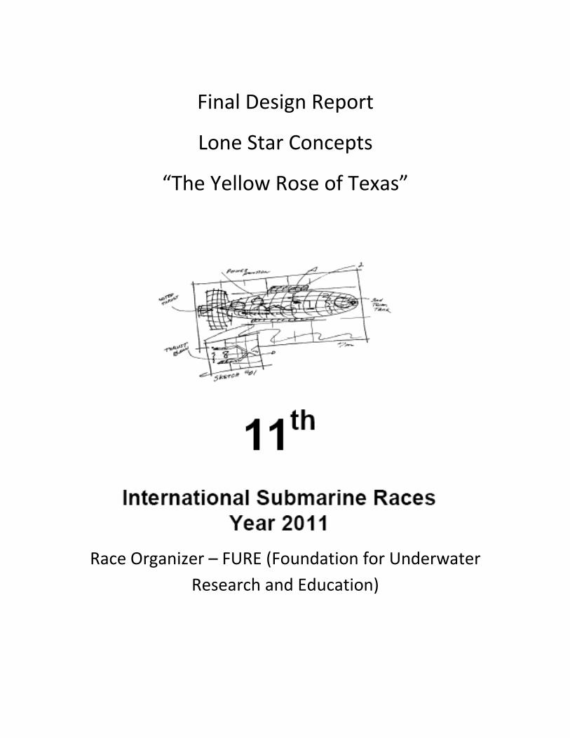
Final Design Report
Lone Star Concepts
“The Yellow Rose of Texas”
Race Organizer – FURE (Foundation for Underwater
Research and Education)
2
Introduction:
Four guys from Waller TX decided to build a human powered vehicle, Keith, Daniel, Michael and
Joe, to compete in the International Submarine Races, ISR 11. We intended this to be a
Research and Design challenge and a chance to have an out of the ordinary fun experience.
Design Philosophy:
Question everything: This was the overriding design criteria in our design and build
efforts.
This is a human powered vehicle race not a submarine race. It just happens to be the
fluid media water.
We evaluated all of the submarines from previous years and looked for the best
features and ideas from each.
Research each design feature to try to validate prior to inclusion in our design.
We began with no preconceived ideas in creating our submarine design.
Design Assumptions:
The pilot’s physical position within the vehicle directly impacts the amount of power
that can be extracted and utilized.
Low available pilot power output requires efficiently applying this power to the
propulsion system.
The efficiency of the power transmission systems affects the torque that is available at
the propeller.
The weight of the vehicle components does not matter since the vehicle is neutrally
buoyant.
The vehicle volume is critical: the more displacement the vehicle has, the more difficult
it will be to accelerate.
The use of a tubular or cigar submarine shape as the primary structural feature severely
limits the optimal placement, maintenance and utilization of all systems.
The use of Commercial Off The Shelf (COTS) components simplifies the engineering
requirements since the manufacturers have qualified component specifications.
The ability to maintain, replace components and service the vehicle adds flexibility to
adjust capabilities as needed.
3
Utilizing the KISS (Keep It Simple Stupid) design philosophy will allow the vehicle to be
less costly and more reliable.
The use of solid modeling software will allow us to go from “art to part” with limited
team resources.
All safety requirements of ISR #11 will be designed in and installed.
Design Results:
The use of a recumbent pilot position utilizing the arms, legs and back for power. (Fig 1)
The use of an internally developed “Linear Drive” system. (Fig 2)
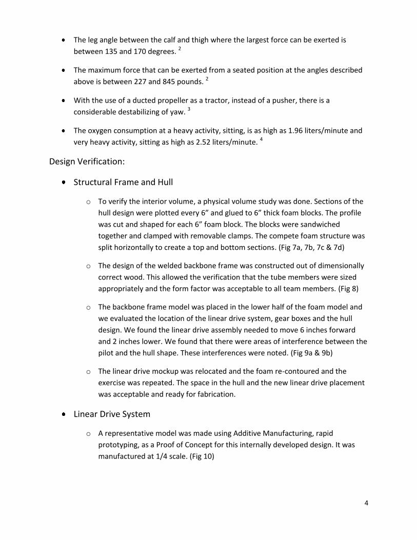
The use of a welded frame with all propulsion and control systems attached. The hull is
an attachment and not a constricting element to the design. (Fig 3)
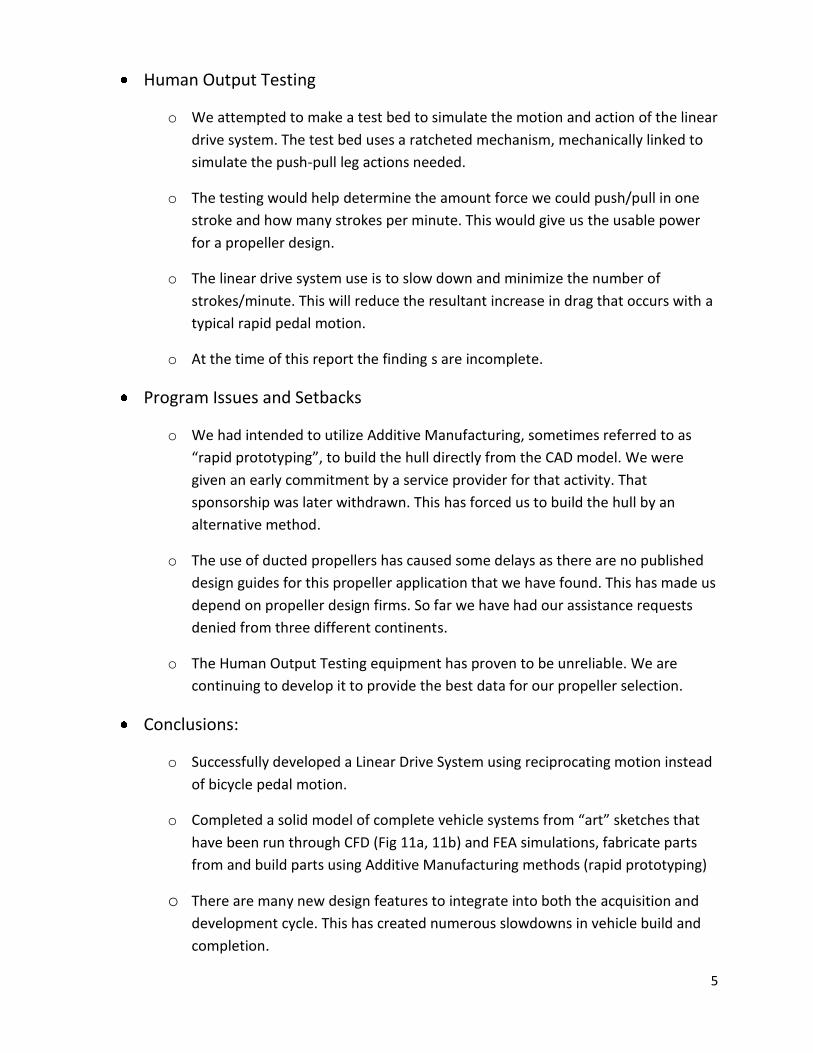
The use of commercially available drive train assemblies. (Fig 4)
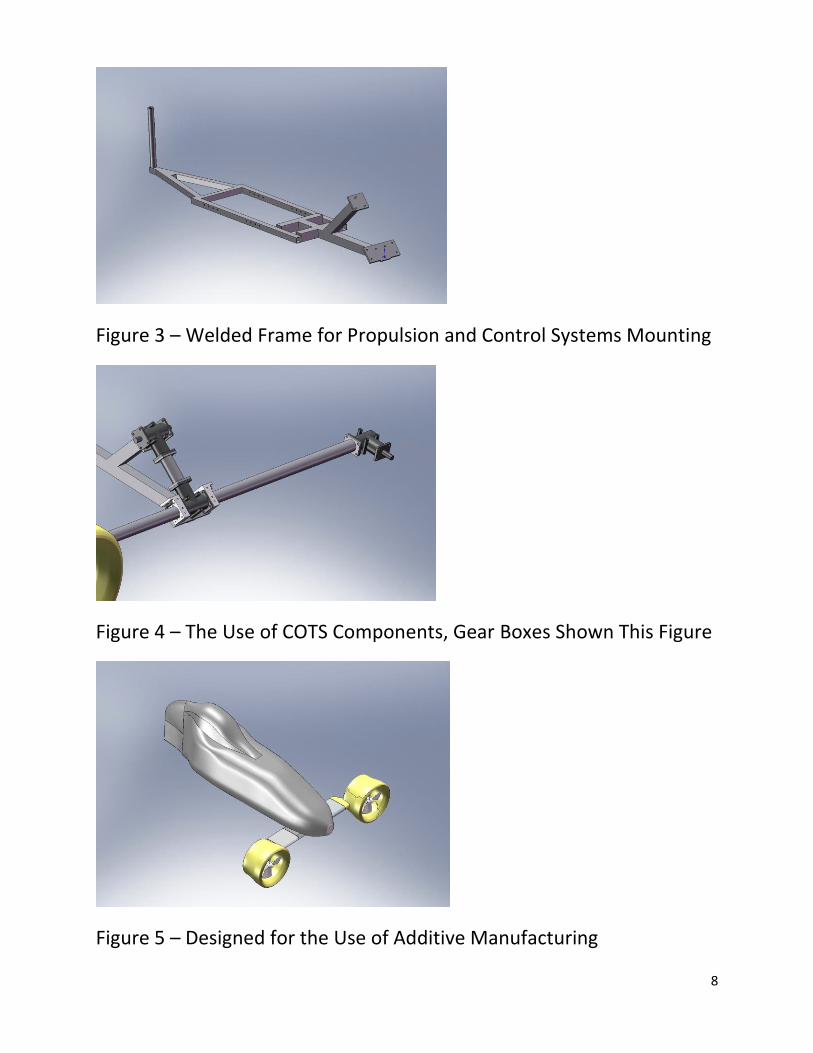
Minimizing displacement, even at the loss of hydrodynamic form. This will allow for
quicker acceleration and top speed. (Fig 5)
The use of additive manufacturing to create the hull surfaces, control surfaces and
propeller nozzles. (Fig 5)
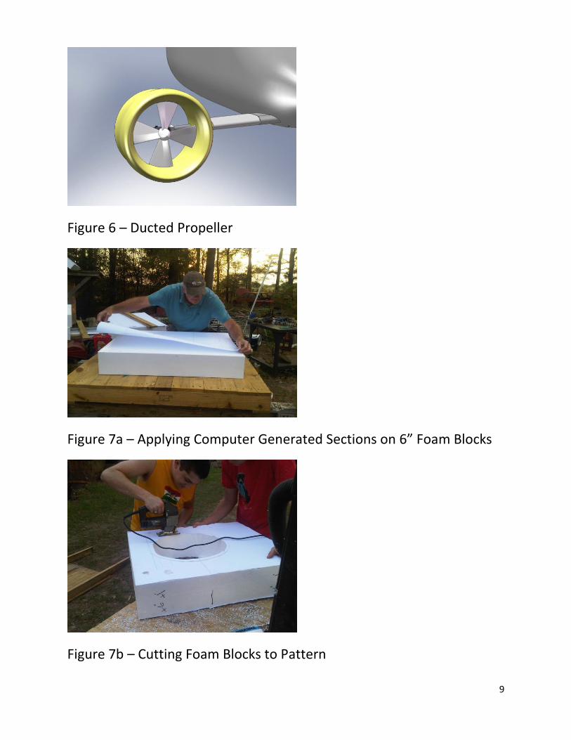
The utilization of dual, counter-rotating ducted propeller assemblies. (Fig 6)
Design Research Validation:
Research into propeller efficiency indicated that a shrouded propeller, over an open
propeller, will have a higher bollard pull capacity of around 20%. Some sources quoted
as high as a 50% improvement. Shrouded propellers are effective up to 12-14 knots.
(multiple published sources)
Research showed that the highest speed obtained by a Human Powered vehicle
operating in the fluid air is a recumbent bicycle at 83 mph / 133 kph. (multiple published
sources)
The most common placement of propellers in vehicles that operate with air as their fluid
media is an airplane with forward placed propellers. This places them in the calm air and
allows for pulling the craft, rather than pushing.
The effect of the pilot’s foot velocity had a significant increase in drag force, but minimal
on drag coefficient values. 1
4
The leg angle between the calf and thigh where the largest force can be exerted is
between 135 and 170 degrees. 2
The maximum force that can be exerted from a seated position at the angles described
above is between 227 and 845 pounds. 2
With the use of a ducted propeller as a tractor, instead of a pusher, there is a
considerable destabilizing of yaw. 3
The oxygen consumption at a heavy activity, sitting, is as high as 1.96 liters/minute and
very heavy activity, sitting as high as 2.52 liters/minute. 4
Design Verification:
Structural Frame and Hull
o To verify the interior volume, a physical volume study was done. Sections of the
hull design were plotted every 6” and glued to 6” thick foam blocks. The profile
was cut and shaped for each 6” foam block. The blocks were sandwiched
together and clamped with removable clamps. The compete foam structure was
split horizontally to create a top and bottom sections. (Fig 7a, 7b, 7c & 7d)
o The design of the welded backbone frame was constructed out of dimensionally
correct wood. This allowed the verification that the tube members were sized
appropriately and the form factor was acceptable to all team members. (Fig 8)
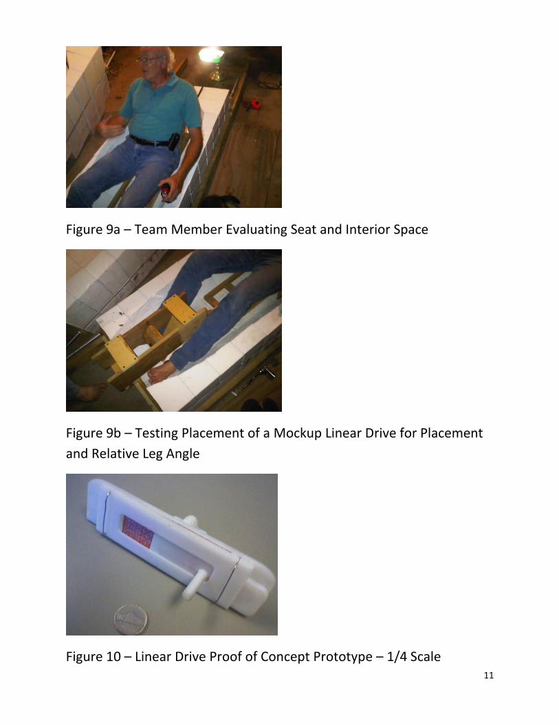
o The backbone frame model was placed in the lower half of the foam model and
we evaluated the location of the linear drive system, gear boxes and the hull
design. We found the linear drive assembly needed to move 6 inches forward
and 2 inches lower. We found that there were areas of interference between the
pilot and the hull shape. These interferences were noted. (Fig 9a & 9b)
o The linear drive mockup was relocated and the foam re-contoured and the
exercise was repeated. The space in the hull and the new linear drive placement
was acceptable and ready for fabrication.
Linear Drive System
o A representative model was made using Additive Manufacturing, rapid
prototyping, as a Proof of Concept for this internally developed design. It was
manufactured at 1/4 scale. (Fig 10)
5
Human Output Testing
o We attempted to make a test bed to simulate the motion and action of the linear
drive system. The test bed uses a ratcheted mechanism, mechanically linked to
simulate the push-pull leg actions needed.
o The testing would help determine the amount force we could push/pull in one
stroke and how many strokes per minute. This would give us the usable power
for a propeller design.
o The linear drive system use is to slow down and minimize the number of
strokes/minute. This will reduce the resultant increase in drag that occurs with a
typical rapid pedal motion.
o At the time of this report the finding s are incomplete.
Program Issues and Setbacks
o We had intended to utilize Additive Manufacturing, sometimes referred to as
“rapid prototyping”, to build the hull directly from the CAD model. We were
given an early commitment by a service provider for that activity. That
sponsorship was later withdrawn. This has forced us to build the hull by an
alternative method.
o The use of ducted propellers has caused some delays as there are no published
design guides for this propeller application that we have found. This has made us
depend on propeller design firms. So far we have had our assistance requests
denied from three different continents.
o The Human Output Testing equipment has proven to be unreliable. We are
continuing to develop it to provide the best data for our propeller selection.
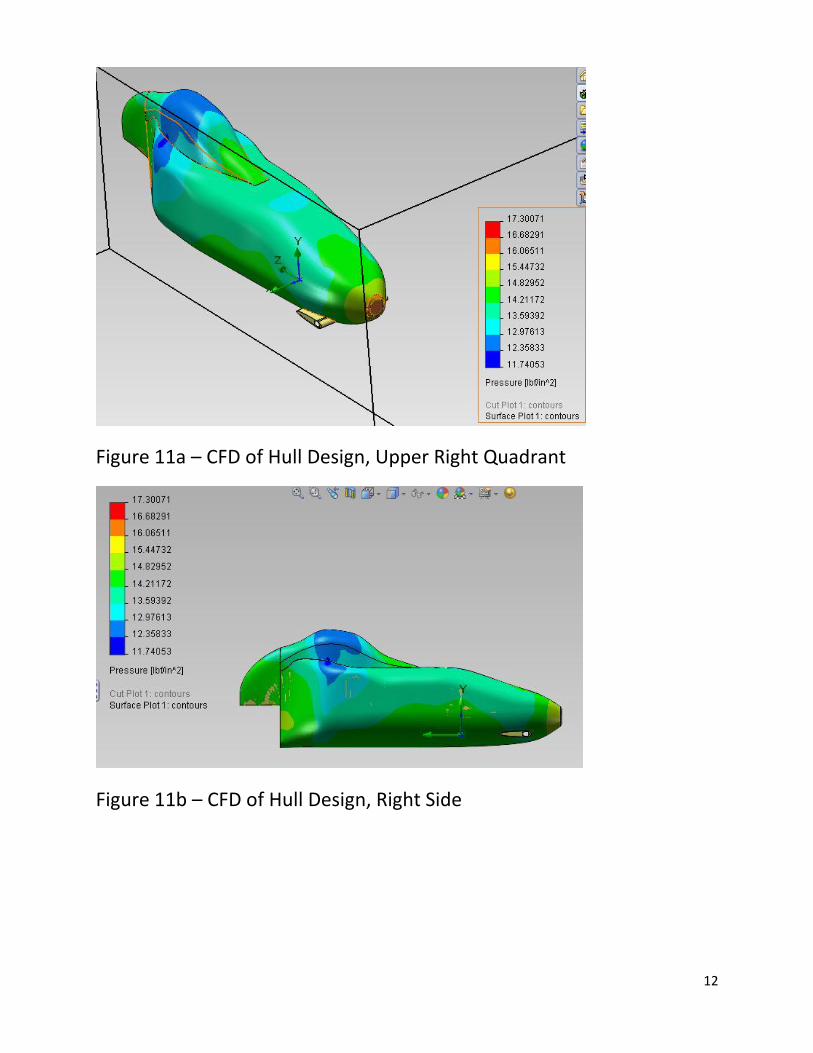
Conclusions:
o Successfully developed a Linear Drive System using reciprocating motion instead
of bicycle pedal motion.
o Completed a solid model of complete vehicle systems from “art” sketches that
have been run through CFD (Fig 11a, 11b) and FEA simulations, fabricate parts
from and build parts using Additive Manufacturing methods (rapid prototyping)
o There are many new design features to integrate into both the acquisition and
development cycle. This has created numerous slowdowns in vehicle build and
completion.

6
Current Sponsor Participation
o DiveTech of Houston, TX provided SCUBA training for all 4 team members. They
also are providing rental for equipment for the competition.
o AnglGear, a group of Andantex, provided the miter gear boxes.
o GoEngineer has provided SolidWorks design software and design analysis, CFD
and FEA.
o VersaBar has committed to providing travel expense funds and propeller
acquisition.
o Artech Manufacturing is providing machining and fabrication services.
o Vision Manufacturing is providing manufacturing services.
o R&M Energy Services-Tomball facility has provided engineering services.
Citations for Research Data:
1. Determination of hydrodynamic drag forces and drag coeffients on human
leg/foot model during knee exercise: Poyhonen, T, Keskinen KL, Hautala A,
Malkia E, Department of Health Sciences, University of Jyvaskyla, Jyvaskyla,
Finland
2. Pedal force-Limits Expectations: CT Morgan et al, “Human Engineering Guide to
Equipment Design”, McGraw-Hill Book Company, New York, a963, pp 569, 570
3. The ducted Propeller for STOL Airplanes, August Raspet, Aerophysics Depatment,
Mississippi State University, State College, Miss., ASME, 1960, Studies conducted
under the office on Naval Research Contract.
4. Work, Heat and Oxygen Costs: P Webb, Bioastronautics Data Book (2nd ed,
National Aeronautics and Space Administration), 1973

7
Figure 1 – Recumbent Pilot Position
Figure 2a – Linear Drive System Showing Drive Rack
Figure 2b – Linear Drive System Showing Complete Assembly Design
8
Figure 3 – Welded Frame for Propulsion and Control Systems Mounting
Figure 4 – The Use of COTS Components, Gear Boxes Shown This Figure
Figure 5 – Designed for the Use of Additive Manufacturing
9
Figure 6 – Ducted Propeller
Figure 7a – Applying Computer Generated Sections on 6” Foam Blocks
Figure 7b – Cutting Foam Blocks to Pattern

10
Figure 7c – Fully Assembled Vehicle Interior Study
Figure 7d – Hull Split Horizontally Ready for Interior Space Study
Figure 8 – Structural Frame & Seat Mockup Placed Inside Foam Interior
Study
11
Figure 9a – Team Member Evaluating Seat and Interior Space
Figure 9b – Testing Placement of a Mockup Linear Drive for Placement
and Relative Leg Angle
Figure 10 – Linear Drive Proof of Concept Prototype – 1/4 Scale
12
Figure 11a – CFD of Hull Design, Upper Right Quadrant
Figure 11b – CFD of Hull Design, Right Side