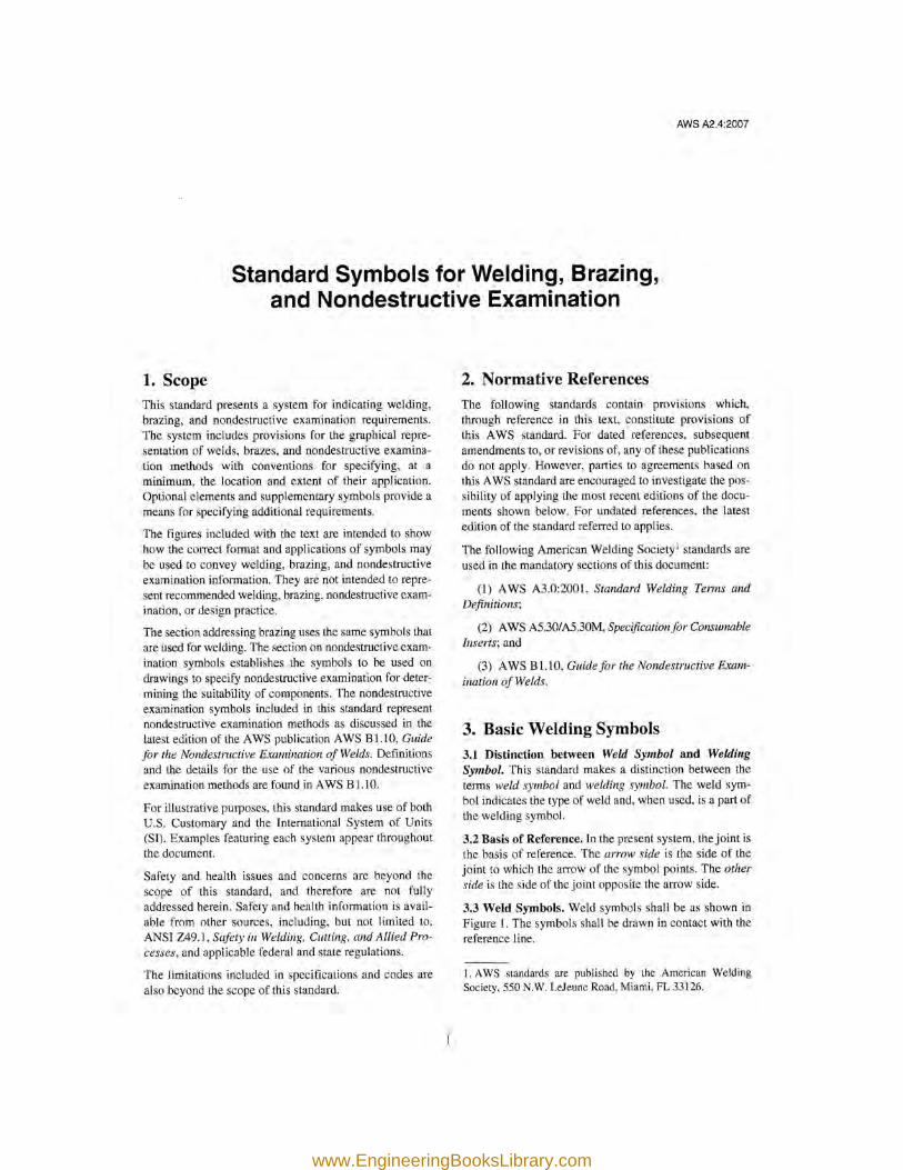
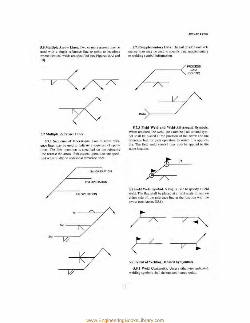
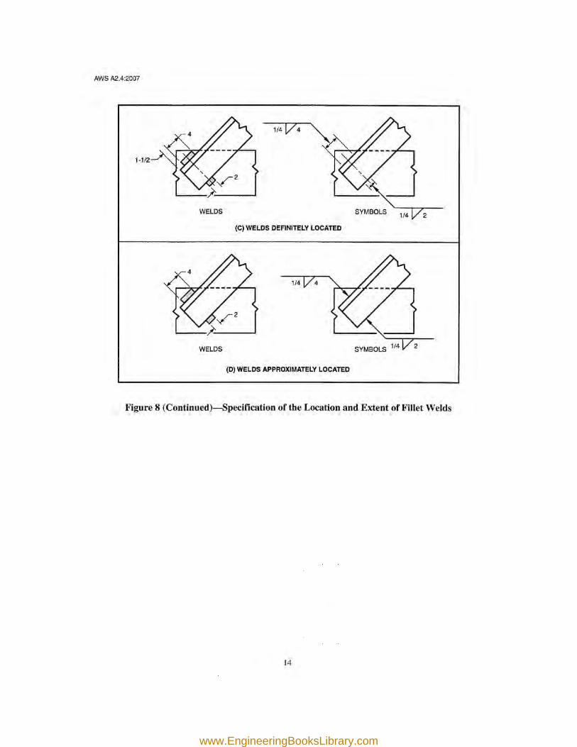
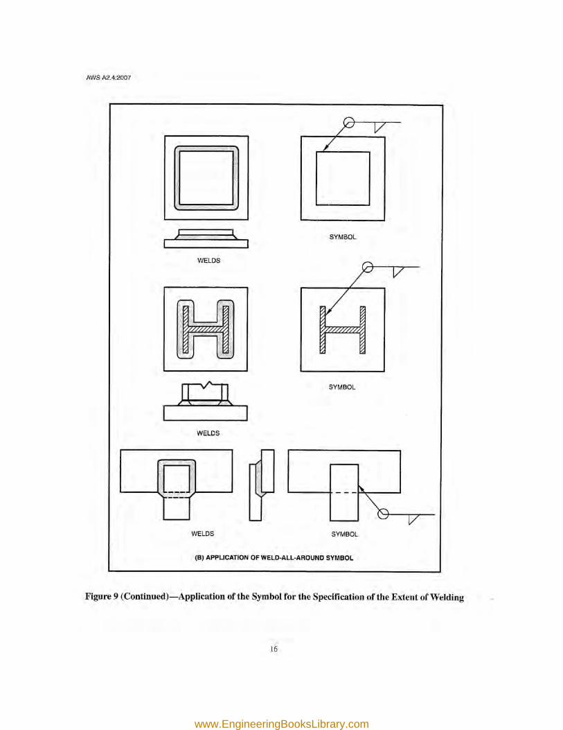
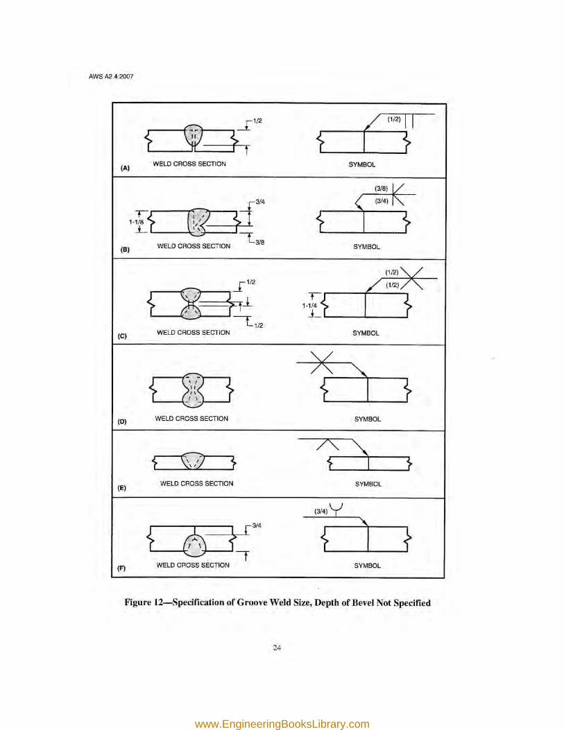

FIELD WELDING PROCEDURES - dl.otvet.gov.et
156
BUILDING NORTH CAROLINA’S FUTURE (Steel Section) FIELD WELDING PROCEDURES Sunset Beach, NC Cleveland, NC www.EngineeringBooksLibrary.com
Transcript of FIELD WELDING PROCEDURES - dl.otvet.gov.et
BUILDING NORTH CAROLINA’S FUTURE
(Steel Section)
FIELD WELDING PROCEDURES
Sunset Beach, NC
Cleveland, NC
www.EngineeringBooksLibrary.com
(Steel Section)
FIELD
WELDING
PROCEDURES
4th Edition-June 2011
www.EngineeringBooksLibrary.com
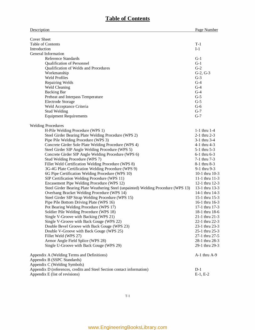
Table of Contents
Description Page Number Cover Sheet Table of Contents T-1 Introduction I-1 General Information Reference Standards G-1 Qualification of Personnel G-1 Qualification of Welds and Procedures G-2 Workmanship G-2, G-3 Weld Profiles G-3 Repairing Welds G-4 Weld Cleaning G-4 Backing Bar G-4 Preheat and Interpass Temperature G-5 Electrode Storage G-5 Weld Acceptance Criteria G-6 Stud Welding G-7 Equipment Requirements G-7 Welding Procedures H-Pile Welding Procedure (WPS 1) 1-1 thru 1-4 Steel Girder Bearing Plate Welding Procedure (WPS 2) 2-1 thru 2-3 Pipe Pile Welding Procedure (WPS 3) 3-1 thru 3-4 Concrete Girder Sole Plate Welding Procedure (WPS 4) 4-1 thru 4-3 Steel Girder SIP Angle Welding Procedure (WPS 5) 5-1 thru 5-3 Concrete Girder SIP Angle Welding Procedure (WPS 6) 6-1 thru 6-3 Stud Welding Procedure (WPS 7) 7-1 thru 7-3 Fillet Weld Certification Welding Procedure (WPS 8) 8-1 thru 8-3 3G-4G Plate Certification Welding Procedure (WPS 9) 9-1 thru 9-3 6G Pipe Certification Welding Procedure (WPS 10) 10-1 thru 10-3 SIP Certification Welding Procedure (WPS 11) 11-1 thru 11-3 Encasement Pipe Welding Procedure (WPS 12) 12-1 thru 12-3 Steel Girder Bearing Plate Weathering Steel (unpainted) Welding Procedure (WPS 13) 13-1 thru 13-3 Overhang Bracket Welding Procedure (WPS 14) 14-1 thru 14-3 Steel Girder SIP Strap Welding Procedure (WPS 15) 15-1 thru 15-3 Pipe Pile Bottom Driving Plate (WPS 16) 16-1 thru 16-3 Pot Bearing Welding Procedure (WPS 17) 17-1 thru 17-3 Soldier Pile Welding Procedure (WPS 18) 18-1 thru 18-6 Single V-Groove with Backing (WPS 21) 21-1 thru 21-3 Single V-Groove with Back Gouge (WPS 22) 22-1 thru 22-3 Double Bevel Groove with Back Gouge (WPS 23) 23-1 thru 23-3 Double V-Groove with Back Gouge (WPS 25) 25-1 thru 25-3 Fillet Weld (WPS 27) 27-1 thru 27-5 Armor Angle Field Splice (WPS 28) 28-1 thru 28-3 Single U-Groove with Back Gouge (WPS 29) 29-1 thru 29-3 Appendix A (Welding Terms and Definitions) A-1 thru A-9 Appendix B (SSPC Standards) Appendix C (Welding Symbols) Appendix D (references, credits and Steel Section contact information) D-1 Appendix E (list of revisions) E-1, E-2
T-1
www.EngineeringBooksLibrary.com
Introduction
The information contained within this book of Approved Welding Procedures is intended to assist the NCDOT Construction Inspector and guide the Welding Contractor with acceptable procedures and practices for the application of weld in a field environment on NCDOT bridge projects. Additional information and procedures have been included to assist Bridge Maintenance Personnel with "Repair of Existing Structures". The information is in no way considered to be complete or all encompassing but instead offers aid to some of the most common applications to field welding that are found on NCDOT bridge construction projects. A Welding Procedure Specification (WPS) may be generated by an authorized person (i. e. CWI) and then submitted to the NCDOT Materials & Tests Unit (Steel Section) at 770A Park Centre Drive in Kernersville, NC 27284 (phone: 336-993-2300) for approval in the event that the contractor does not want to utilize the material provided. These approved welding procedures may also be found at the following web address: http://www.ncdot.org/doh/operations/materials/structural/appr_proc.html This manual may also be found at the following web address: http://www.ncdot.org/doh/operations/materials/pdf/fwp.pdf Previous editions of this manual include: 1st Edition-October 2008 2nd Edition-April 2009 3rd Edition-May 2010
I-1
www.EngineeringBooksLibrary.com
General Information
Reference Standards As stated by the NCDOT “Standard Specifications For Roads and Bridges JULY 2006” page 4-55 section 440-7: “Perform field welding only when called for on the plans and in accordance with 1072-20.” “Remove paint or galvanizing at the location of field welds by blast cleaning (SSPC SP-6 finish), or hand (SSPC SP-2 finish) or power tool cleaning (SSPC SP-3 finish) just prior to welding. Clean sufficiently to prevent contamination of the weld by the paint.” note: Refer to Appendix B for SSPC standards. The NCDOT “Standard Specifications For Roads and Bridges JULY 2006” page 10-141 section 1072-20 makes reference to the ANSI/AWS/AASHTO Bridge Welding Code D-1.5 and states in section 1072-20 (B) General “Weld all structural steel in the shop or in the field for bridges, whether permanent or temporary, and perform all other work related to structural welding including, but not limited to, testing and inspection of welds, preparation of material, oxygen cutting, electrodes, shielding, and shear studs, meeting the requirements of the Bridge Welding Code. Weld other steel items in accordance with the requirements of the applicable AWS Welding Code.” "Weld only where shown on the plans or where called for in the Specifications unless requesting and receiving written approval for additional welding." Additional governing information pertaining to field welding can be found on contract documents such as NCDOT approved plans and special provisions.
Qualification of Personnel For the purpose of field welding on NCDOT construction projects, all personnel must be tested and approved by the NCDOT Materials & Tests Unit (Steel Section). Prior to performing any welding activities, the qualified person must present the Welder ID card that was issued by the M & T Unit along with another photo ID, such as a driver’s license, to the NCDOT representative (i. e. Construction Inspector). Currently there are three levels of NCDOT field welder certification.
SIP Welder- This certification qualifies a welder to weld stay in place deck forms to girders. Bridge Welder- This certification qualifies a welder to weld anything on a project except pipe less than 24 inches in diameter. Pipe Welder: This certification qualifies a welder to weld anything on a project.
Additional information about welder certification can found at the following web address: http://www.ncdot.org/doh/operations/materials/pdf/fwcprocedure.pdf
G-1
www.EngineeringBooksLibrary.com
Qualification of Welds and Procedures
(7-21-09) SP10 R43 Page 10-143, Subarticle 1072-20(D) Qualification of Welds and Procedures, replace the third sentence of the first paragraph with the following: For all prequalified field welds, submit Welding Procedure Specifications (WPS) for each joint configuration for approval at least 30 days prior to performing any welding. In lieu of this, use the WPS provided and pre-approved by the Department. These pre-approved WPSs are available from the Materials and Tests Unit or at: http://www.ncdot.org/doh/operations/materials/structural/appr_proc.html Use non-prequalified welds only if approved by the Engineer. Submit WPS for all non-prequalified welds to the Engineer for approval. At no cost to the Department, demonstrate their adequacy in accordance with the requirements of the Bridge Welding Code.
Application AWS D-1.5 Section 1.1.1 This code covers welding fabrication requirements applicable to welded highway bridges. The code is applicable to both shop and field fabrication of steel bridges and bridge components,
Workmanship AWS D-1.5 Section 3.1.3 Welding shall not be done when the ambient temperature is lower than 0° F, when surfaces are wet or exposed to rain, snow, or high wind velocities, nor when welders are exposed to inclement conditions. AWS D-1.5 Section 3.2.1 Surfaces and edges to be welded shall be smooth, uniform, and free from fins, tears, cracks, and other discontinuities which would adversely affect the quality or strength of the weld. Surfaces to be welded and surfaces adjacent to a weld shall also be free from loose or thick scale, slag, rust, moisture, grease, and other foreign material that would prevent proper welding or produce objectionable fumes. Mill scale that can withstand vigorous wire brushing, a thin rust-inhibitive coating, or antispatter compound may remain… AWS D-1.5 Section 3.2.2 In all thermal cutting, the cutting flame shall be so adjusted and manipulated as to avoid cutting beyond (inside) the prescribed lines. The roughness of thermal cut surfaces shall be no greater than that defined by the American National Standards Institute, ANSI B46.1, Surface Texture. For material up to 100mm [4 in] thick, the maximum surface roughness value shall be 25 µm (1000 µin). Steel and weld metal may be thermally cut, provided a smooth and regular surface free from cracks and notches is secured, and provided that an accurate profile is secured by the use of a mechanical guide. Free-hand thermal cutting shall be done only where approved by the Engineer.
G-2
www.EngineeringBooksLibrary.com
Workmanship (cont.)
AWS D-1.5 Section 3.2.4 Reentrant corners of base-metal cut edges shall be formed to provide a smooth transition with a radius of not less than 25mm [1 in] that meets the adjacent edges without offset or cutting past the point of tangency. The reentrant corners must be formed by thermal cutting, followed by grinding to meet the surface requirements of 3.2.2. AWS D-1.5 Section 3.3.1 The parts to be joined by fillet welds shall be brought into as close contact as practical. The root opening shall not exceed 3/16” except in cases involving either shapes or plates 3” or greater in thickness if, after straightening and in assembly, the root opening cannot be closed sufficiently to meet this tolerance. … If the root opening is greater than 1/16”, the leg of the fillet weld shall be increased by the amount of the root opening or the Contractor shall demonstrate that the required weld size has been obtained.
AWS D-1.5 Section 3.3.1.2 The use of filler plates shall be prohibited except as specified on the drawings or as specially approved by the Engineer…
AWS D-1.5 Section 3.3.3 Parts to be joined by groove welds shall be carefully aligned. Where the parts are effectively restrained against bending due to eccentricity in alignment, the offset from theoretical alignment shall not exceed 10% of the thickness of the thinner part joined, but in no case shall be more than 1/8”. AWS D-1.5 Section 3.3.7 Tack welds shall be subject to the same quality requirements as the final welds. AWS D-1.5 Section 3.3.8 Temporary welds shall be subject to the same WPS requirements as final welds. They shall be removed unless otherwise allowed by the Engineer. When they are removed, the surface shall be made flush with the original surface. There shall be no temporary welds in tension zones…
Weld Profiles
AWS D-1.5 Section 3.6.1.1 (in reference to fillet weld profiles) The convexity of a weld or individual surface bead shall not exceed 0.07 times the actual face width of the weld or individual bead, respectively, plus 1.5mm [0.06 in]. AWS D-1.5 Section 3.6.2 (in reference to groove weld profiles) Groove welds shall preferably be made with slight or minimum face reinforcement except as may be otherwise provided. In the case of butt and corner joints, the face reinforcement shall not exceed 3mm [1/8 in] in height and shall have gradual transition to the plane of the base surface... They shall be free of the discontinuities shown for butt joints... AWS D-1.5 Section 3.6.5 Welds shall be free from overlap.
G-3
www.EngineeringBooksLibrary.com
Repairing Welds
AWS D-1.5 Section 3.7.2 The Contractor has the option of either repairing an unacceptable weld, or removing and replacing the entire weld... If the Contractor elects to repair the weld, it shall be corrected as follows:
AWS D-1.5 Section 3.7.2.1 Overlap or Excessive Convexity. Excess weld metal shall be removed. AWS D-1.5 Section 3.7.2.2 Excessive Concavity of Weld or Crater, Undersize Welds, Undercutting. Surfaces shall be prepared (see 3.11) and additional weld metal deposited. AWS D-1.5 Section 3.7.2.3 Excessive Weld Porosity, Excessive Slag Inclusions, Incomplete Fusion. Unacceptable portions shall be removed and re-welded. AWS D-1.5 Section 3.7.2.4 Cracks in Weld or Base Metal. The extent of the crack shall be ascertained by use of MT, PT, or other equally positive means; the metal shall be removed for the full length of the crack plus 500mm [2 in] beyond each end of the crack, and re-welded.
Weld Cleaning
AWS D-1.5 Section 3.11.1 In-Process Cleaning. Before welding over previously deposited metal, all slag shall be removed and the weld and adjacent base metal shall be brushed clean. This requirement shall apply not only to successive layers but also to successive beads and to the crater area when welding is resumed after an interruption... AWS D-1.5 Section 3.11.2 Cleaning of Completed Welds. Slag shall be removed from all completed welds, and the weld and adjacent base metal shall be cleaned by brushing or other suitable means. Tightly adherent spatter remaining after the cleaning operation shall be acceptable unless its removal shall be required for the purpose of NDT or painting. Welded joints shall not be painted until after welding has been completed and the weld has been accepted.
Backing Bar AWS D-1.5 Section 3.13.5 Steel backing shall be placed and held in intimate contact with the base metal. The maximum gap between steel backing and the base metal at the weld root shall be 2 mm (1/16 in).
G-4
www.EngineeringBooksLibrary.com
Preheat and Interpass Temperature
Unless stated otherwise on the approved welding procedure, all preheat temperatures on NCDOT projects shall be 100° F. AWS D-1.5 Section 4.2.7 When the base metal is below the temperature listed for the welding process being used and the thickness of material being welded, it shall be preheated (except as otherwise provided) in such a manner that the steel on which weld metal is being deposited is at or above the specified minimum temperature for a distance equal to the thickness of the part being welded, but not less than 75mm [3 in] in all directions from the point of welding. AWS D-1.5 Section 4.2.8 Preheat and Interpass Temperature Requirements When the base metal temperature is below 0° C [32° F], the base metal shall be heated to at least 20° C [70° F], and this minimum temperature shall be maintained during welding.
Electrode Storage AWS D-1.5 Section 4.5.2 All electrodes having low hydrogen coverings conforming to AWS 5.1/A5.1M shall be purchased in hermetically sealed containers… Immediately after opening the hermetically sealed container or removal of the electrodes from drying ovens, electrodes shall be stored in ovens held at a temperature of at least 120°C [250°F]. After the opening of hermetically sealed containers or removal from drying or storage ovens, electrode exposure to the atmosphere shall not exceed the requirements of 4.5.2.1.
AWS D-1.5 Section 4.5.2.1 Electrodes exposed to the atmosphere upon removal from drying or storage ovens or hermetically sealed containers shall be used within the time limit shown in Table 4.7… AWS D-1.5 Section 4.5.2.2 Electrodes exposed to the atmosphere for periods less than those allowed by Table 4.7 may be returned to a holding oven maintained at 250° F minimum and after a minimum period of four hours at that temperature may be reissued. The Provisions of 4.5.4 shall apply.
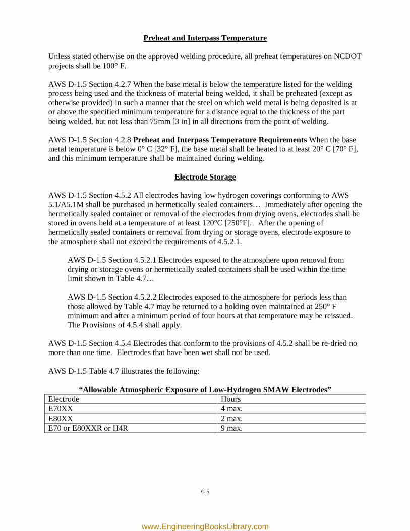
AWS D-1.5 Section 4.5.4 Electrodes that conform to the provisions of 4.5.2 shall be re-dried no more than one time. Electrodes that have been wet shall not be used. AWS D-1.5 Table 4.7 illustrates the following:
“Allowable Atmospheric Exposure of Low-Hydrogen SMAW Electrodes” Electrode Hours E70XX 4 max. E80XX 2 max. E70 or E80XXR or H4R 9 max.
G-5
www.EngineeringBooksLibrary.com
Weld Acceptance Criteria
AWS D-1.5 Section 6.26.1 All welds shall be visually inspected. A weld shall be acceptable by visual inspection if it conforms to the following requirements:
AWS D-1.5 Section 6.26.1.1 The weld shall have no cracks. AWS D-1.5 Section 6.26.1.2 Thorough fusion shall exist between adjacent layers of weld metal and between weld metal and base metal. AWS D-1.5 Section 6.26.1.3 All craters are to be filled to the full cross section of the weld... AWS D-1.5 Section 6.26.1.4 Weld profiles shall be in conformance with 3.6. AWS D-1.5 Section 6.26.1.5 In primary members, undercut shall be no more than 0.25mm [0.01 in] deep when the weld is transverse to tensile stress under any design loading condition. Undercut shall be no more than 1mm [1/32 in] deep for all other cases. Porosity limitation guidelines (AWS D-1.5 Section 6.26.1.6) are too complex to be presented in this manual. Contact the M&T Unit (Steel Section) for technical assistance regarding discontinuities of this type. AWS D-1.5 Section 6.26.1.7 A fillet weld in any single continuous weld may under run the nominal fillet weld size specified by 2mm [1/16 in] without correction, provided that the undersize portion of the weld does not exceed 10% of the length of the weld.
AWS D-1.5 C-6.26.1 Visual Inspection. All welds are required to be visually inspected. Visual inspection is performed before welding, during welding, and after welding, as necessary to ensure that the requirements of the Contract Documents are met and that all welds conform to the visual requirements of this sub-clause. The Inspector is not required to inspect each weld pass, but periodically observe welding with sufficient frequency to verify the skills of the welder, proper joint preparation, WPS variables, and the visual quality of typical root, intermediate, and final weld passes. In addition to inspection before and during welding, the Inspector is expected to visually inspect every completed weld to verify conformance to these requirements. See C6.5. AWS D-1.5 C-6.5 Each welder, welding operator and tack welder should be a visual inspector of his or her own work. Welding personnel should know when welds display visual discontinuities not acceptable under the Code. Because each weld pass of every weld is to be inspected by the welder, and the inspector monitors welding in progress and makes a detailed inspection of completed welds, major weld defects or gross nonconformance to the Code should be detected.
G-6
www.EngineeringBooksLibrary.com
Stud Welding
Contact the NCDOT M&T Unit (Steel Section) when "automatically timed stud welding equipment" is being used. AWS D-1.5 Section 7.4.1 At the time of welding, the studs shall be free from rust, rust pits, scale, oil, moisture, and other deleterious matter that would adversely affect the welding operations. AWS D-1.5 Section 7.4.2 The stud base shall not be painted, galvanized, nor cadmium-plated prior to welding. AWS D-1.5 Section 7.5.5 At the option of the Contractor, studs may be fillet welded by the SMAW, provided the following requirements are met:
AWS D-1.5 Section 7.5.5.3 The stud base shall be prepared so that the base of the stud fits against the base metal. AWS D-1.5 Section 7.5.5.4 All rust and mill scale at the location of the stud shall be removed from the base metal by grinding. The end of the stud shall also be clean.
Equipment Requirements Any qualified person intending to perform welding on an NCDOT project shall arrive at the job site with all of the appropriate equipment which includes but is not limited to a welding machine that has an adequate power range to produce the amperage necessary to satisfy the WPS requirements, an electrode storage oven to stay within the guidelines of the exposure limits of the welding consumables, a grinder that is suitable for preparing the base metal in the area that is to be welded, a torch or other preheating device that can satisfactorily raise the temperature of the base metal in the area to be welded to the range that is specified in the WPS, approved low hydrogen electrodes that are in a hermetically sealed container or in an active electrode storage oven, clamps or other equipment that is necessary to properly cut, fit and assemble the material to be welded and clean the completed weld. Failure to produce this or other equipment that is needed to complete the work within specifications could result in the Welding Contractor not being permitted to start welding.
G-7
www.EngineeringBooksLibrary.com
1-1
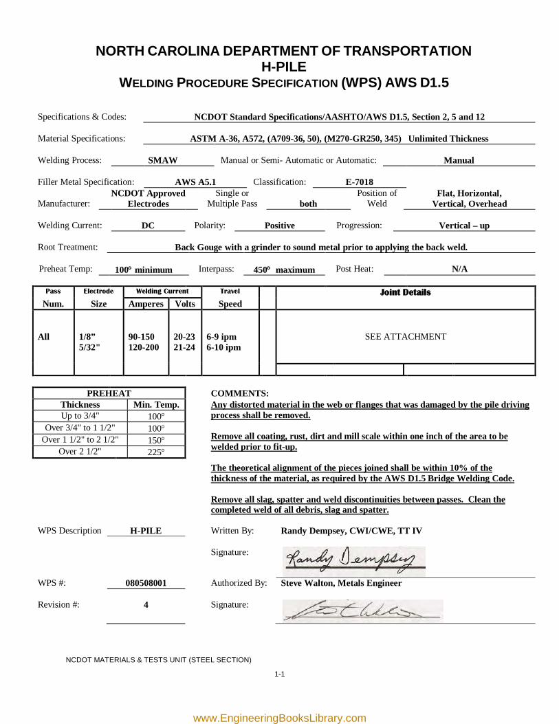
NORTH CAROLINA DEPARTMENT OF TRANSPORTATION H-PILE
WELDING PROCEDURE SPECIFICATION (WPS) AWS D1.5
Specifications & Codes:
NCDOT Standard Specifications/AASHTO/AWS D1.5, Section 2, 5 and 12
Material Specifications:
ASTM A-36, A572, (A709-36, 50), (M270-GR250, 345) Unlimited Thickness
Welding Process:
SMAW
Manual or Semi- Automatic or Automatic:
Manual
Filler Metal Specification:
AWS A5.1
Classification:
E-7018
Manufacturer:
NCDOT Approved Electrodes
Single or Multiple Pass
both
Position of Weld
Flat, Horizontal, Vertical, Overhead
Welding Current:
DC
Polarity:
Positive
Progression:
Vertical – up
Root Treatment:
Back Gouge with a grinder to sound metal prior to applying the back weld.
Preheat Temp:
100° minimum
Interpass:
450° maximum
Post Heat:
N/A
Pass Electrode Welding Current Travel Joint Details
Num. Size Amperes Volts Speed All
1/8” 5/32"
90-150 120-200
20-23 21-24
6-9 ipm 6-10 ipm
SEE ATTACHMENT
PREHEAT COMMENTS: Thickness Min. Temp. Any distorted material in the web or flanges that was damaged by the pile driving
process shall be removed. Remove all coating, rust, dirt and mill scale within one inch of the area to be welded prior to fit-up. The theoretical alignment of the pieces joined shall be within 10% of the thickness of the material, as required by the AWS D1.5 Bridge Welding Code. Remove all slag, spatter and weld discontinuities between passes. Clean the completed weld of all debris, slag and spatter.
Up to 3/4" 100° Over 3/4" to 1 1/2" 100°
Over 1 1/2" to 2 1/2" 150° Over 2 1/2" 225°
WPS Description H-PILE Written By: Randy Dempsey, CWI/CWE, TT IV
Signature:
WPS #: 080508001 Authorized By: Steve Walton, Metals Engineer Revision #:
4
Signature:
NCDOT MATERIALS & TESTS UNIT (STEEL SECTION)
www.EngineeringBooksLibrary.com
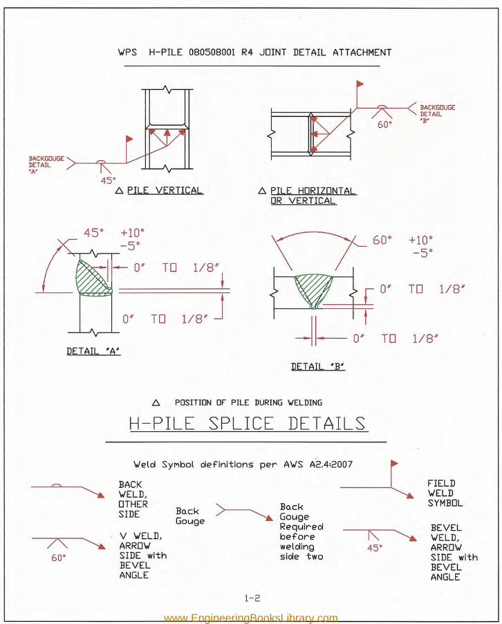
BACK GOUGEDETAIL'A'
45°c: PILE VERTICAL ~ PILE HORIZONTAL
OR VERTICAL
45~ +10~ 60~ +10~-5~ -5~0/1 TO 1/8/1
L 0/1 TO 1/8/1
1/8' J0/1 TO~~O. TO 1/8/1
DETAIL "A"
DETAIL "B'
BACKGOUGEDETAIL'B'
'WPS H-PILE 080508001 R4 JOINT DETAIL ATTACHMENT
c: POSITION OF PILE DURING YIELDING
H-PILE SPLICE DET AILS
'Weld Symbol definitions per A'WS A'2'4'20~
= BACK FIELD~ 'WELD, 'WELD
OTHER~
BQck SYMBOLSIDE BQck
GougeGougeRequired BEVEL
7'\ ~V 'WELD, before r\ ~ 'WELD,ARRo'W welding 45° ARRo'W
60° SIDE with side two SIDE withBEVEL BEVELANGLE ANGLE
1-2
www.EngineeringBooksLibrary.com
1-3
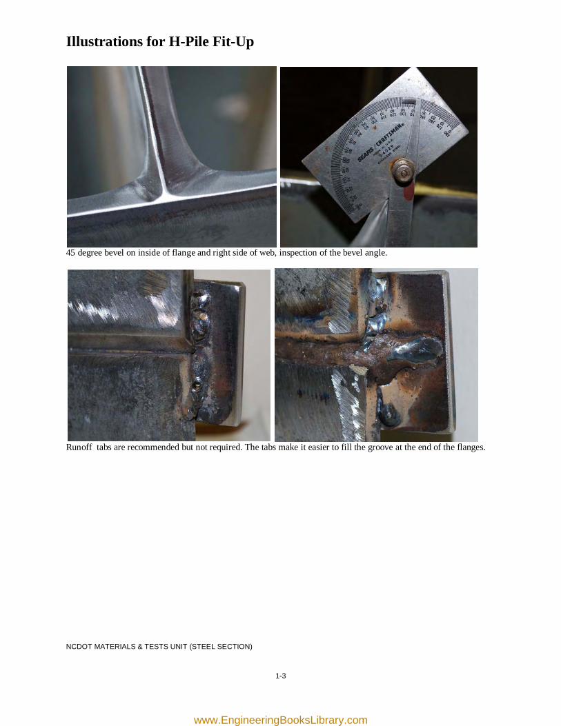
Illustrations for H-Pile Fit-Up
45 degree bevel on inside of flange and right side of web, inspection of the bevel angle.
Runoff tabs are recommended but not required. The tabs make it easier to fill the groove at the end of the flanges. NCDOT MATERIALS & TESTS UNIT (STEEL SECTION)
www.EngineeringBooksLibrary.com
1-4
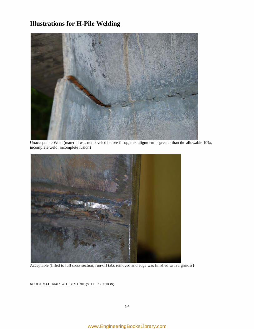
Illustrations for H-Pile Welding
Unacceptable Weld (material was not beveled before fit-up, mis-alignment is greater than the allowable 10%, incomplete weld, incomplete fusion)
Acceptable (filled to full cross section, run-off tabs removed and edge was finished with a grinder) NCDOT MATERIALS & TESTS UNIT (STEEL SECTION)
www.EngineeringBooksLibrary.com
2-1
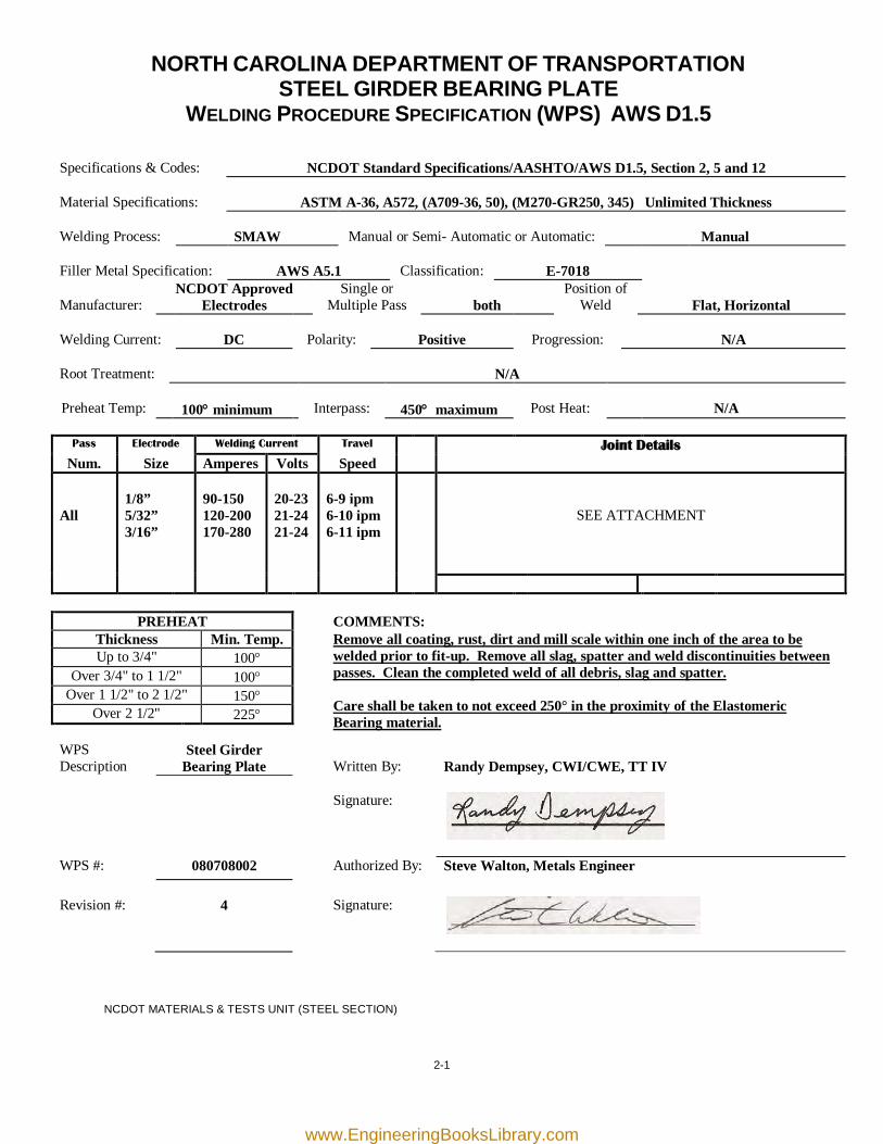
NORTH CAROLINA DEPARTMENT OF TRANSPORTATION STEEL GIRDER BEARING PLATE
WELDING PROCEDURE SPECIFICATION (WPS) AWS D1.5
Specifications & Codes:
NCDOT Standard Specifications/AASHTO/AWS D1.5, Section 2, 5 and 12
Material Specifications:
ASTM A-36, A572, (A709-36, 50), (M270-GR250, 345) Unlimited Thickness
Welding Process:
SMAW
Manual or Semi- Automatic or Automatic:
Manual
Filler Metal Specification:
AWS A5.1
Classification:
E-7018
Manufacturer:
NCDOT Approved Electrodes
Single or Multiple Pass
both
Position of Weld
Flat, Horizontal
Welding Current:
DC
Polarity:
Positive
Progression:
N/A
Root Treatment:
N/A
Preheat Temp:
100° minimum
Interpass:
450° maximum
Post Heat:
N/A
Pass Electrode Welding Current Travel Joint Details
Num. Size Amperes Volts Speed All
1/8” 5/32” 3/16”
90-150 120-200 170-280
20-23 21-24 21-24
6-9 ipm 6-10 ipm 6-11 ipm
SEE ATTACHMENT
PREHEAT COMMENTS: Thickness Min. Temp.
Remove all coating, rust, dirt and mill scale within one inch of the area to be welded prior to fit-up. Remove all slag, spatter and weld discontinuities between passes. Clean the completed weld of all debris, slag and spatter.
Care shall be taken to not exceed 250° in the proximity of the Elastomeric Bearing material.
Up to 3/4" 100° Over 3/4" to 1 1/2" 100°
Over 1 1/2" to 2 1/2" 150° Over 2 1/2" 225°
WPS Description
Steel Girder Bearing Plate
Written By:
Randy Dempsey, CWI/CWE, TT IV
Signature:
WPS #: 080708002 Authorized By: Steve Walton, Metals Engineer Revision #:
4
Signature:
NCDOT MATERIALS & TESTS UNIT (STEEL SECTION)
www.EngineeringBooksLibrary.com
5/16"
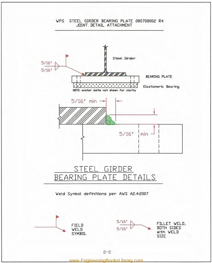
~PS STEEL GIRDER BEARING PLATE 080708002 R4JOINT DETAIL ATTACHMENT
Steel Girder
5/16*
BEARING PLATE
ElQstol'lerlc Beo.rlngNOTE. o.nchor bolts not shown for clo.rlty
__ L
I ,Il""lln
II
STEEL GIRDERBEARING PLATE DETAILS~elcl Synoot cleflnitlons per A~S A2.412007
--lFIELD~ELDSYMBOL
5~5~-V-~ FILLET ~ELDJ
BOTH SIDESwith ~ELDSIZE
2-2
www.EngineeringBooksLibrary.com
2-3
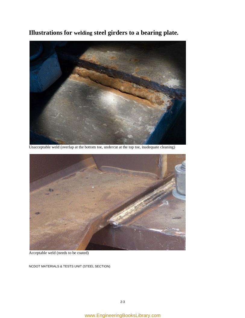
Illustrations for welding steel girders to a bearing plate.
Unacceptable weld (overlap at the bottom toe, undercut at the top toe, inadequate cleaning)
Acceptable weld (needs to be coated) NCDOT MATERIALS & TESTS UNIT (STEEL SECTION)
www.EngineeringBooksLibrary.com

[this page was intentionally left blank]
www.EngineeringBooksLibrary.com
3-1
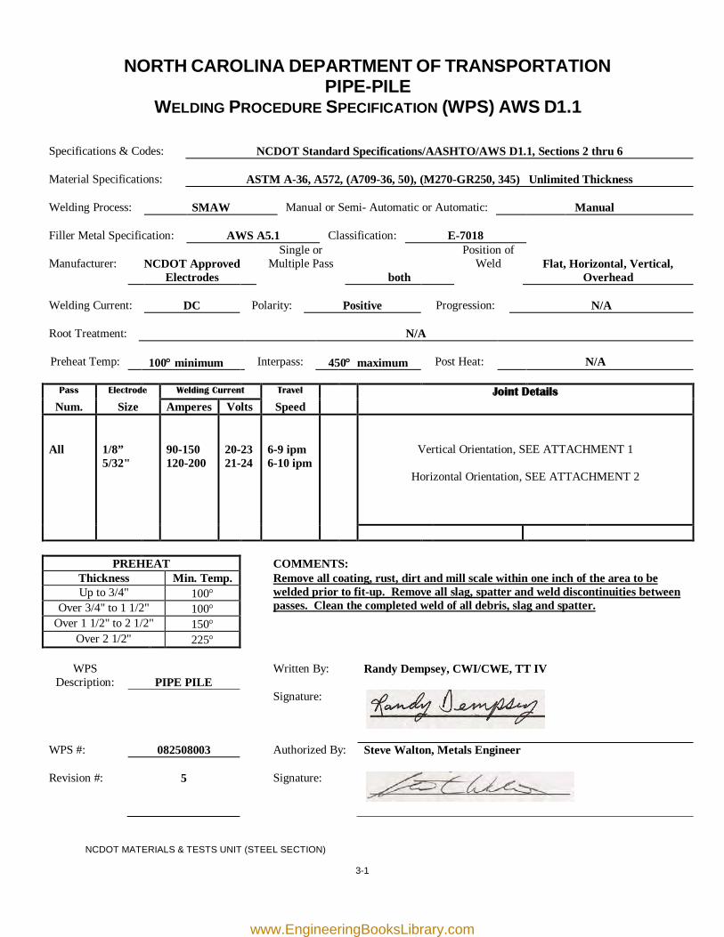
NORTH CAROLINA DEPARTMENT OF TRANSPORTATION PIPE-PILE
WELDING PROCEDURE SPECIFICATION (WPS) AWS D1.1
Specifications & Codes:
NCDOT Standard Specifications/AASHTO/AWS D1.1, Sections 2 thru 6
Material Specifications:
ASTM A-36, A572, (A709-36, 50), (M270-GR250, 345) Unlimited Thickness
Welding Process:
SMAW
Manual or Semi- Automatic or Automatic:
Manual
Filler Metal Specification:
AWS A5.1
Classification:
E-7018
Manufacturer:
NCDOT Approved
Electrodes
Single or Multiple Pass
both
Position of Weld
Flat, Horizontal, Vertical,
Overhead Welding Current:
DC
Polarity:
Positive
Progression:
N/A
Root Treatment:
N/A
Preheat Temp:
100° minimum
Interpass:
450° maximum
Post Heat:
N/A
Pass Electrode Welding Current Travel Joint Details
Num. Size Amperes Volts Speed All
1/8” 5/32"
90-150 120-200
20-23 21-24
6-9 ipm 6-10 ipm
Vertical Orientation, SEE ATTACHMENT 1
Horizontal Orientation, SEE ATTACHMENT 2
PREHEAT COMMENTS: Thickness Min. Temp. Remove all coating, rust, dirt and mill scale within one inch of the area to be
welded prior to fit-up. Remove all slag, spatter and weld discontinuities between passes. Clean the completed weld of all debris, slag and spatter.
Up to 3/4" 100° Over 3/4" to 1 1/2" 100°
Over 1 1/2" to 2 1/2" 150° Over 2 1/2" 225°
WPS
Description:
PIPE PILE Written By: Randy Dempsey, CWI/CWE, TT IV
Signature:
WPS #: 082508003 Authorized By: Steve Walton, Metals Engineer Revision #:
5
Signature:
NCDOT MATERIALS & TESTS UNIT (STEEL SECTION)
www.EngineeringBooksLibrary.com
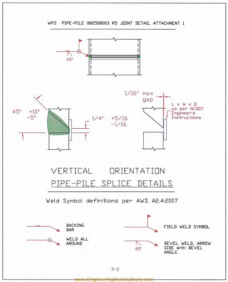
K:45<>
BEVEL W'ELD, ARROW'SIDE with BEVELANGLE
W'PS PIPE-PILE 082508003 R5 JOINT DETAIL ATTACHMENT 1
A
~ I V I
I II I
''''' -------- --45<> r- -- -1
I II A I
V
-, 1/16/1 Mo.Xgo.p
LxW'xD45<> o.s per NCDOT+10<> Engineer's
-5<> 1/4/1 +5/16 Instructions[ -1/16
0\ r
VERTICAL ORIENT ATIONPIPE ~PILE SPLICE DET AILS
\Jeld SYMbol definitions per A\JS A2.4:2007
,......., BACKINGBARW'ELD ALLAROUND
~ . FIELD 'JELD SYMBOL
3-2www.EngineeringBooksLibrary.com
Lx 'vi x Dus per NCDOTEngineer'sInstructions
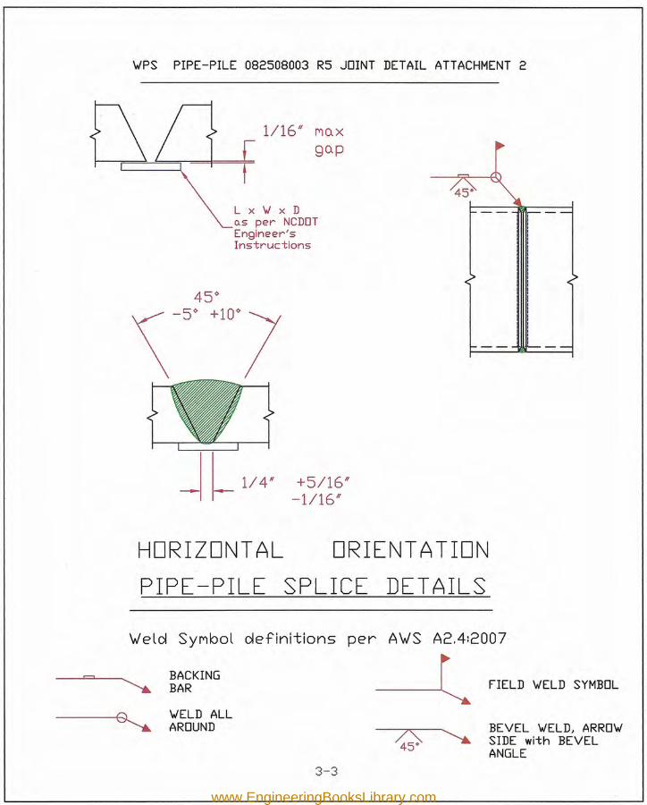
~PS PIPE-PILE 082508003 R5 JOINT DETAIL ATTACHMENT 2
G~ 1/16" Mo.Xgo.p
+5/16"-1/16"
HORIZONTAL ORIENTATIONPIPE -PILE SPLICE DET AILS
W'eld Synbol definitions per AW'S A2.4:2007
r=='1~
BACKING ---lBAR FIELD ~ELD SYMBOL
~~ELD ALLAROUND ;:;;; BEVEL ~ELD, ARRO~
~ SIDE with BEVELANGLE
3-3www.EngineeringBooksLibrary.com
3-4
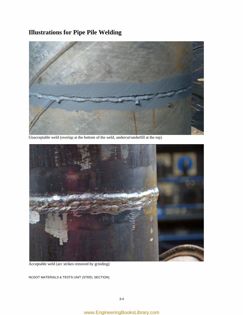
Illustrations for Pipe Pile Welding
Unacceptable weld (overlap at the bottom of the weld, undercut/underfill at the top)
Acceptable weld (arc strikes removed by grinding) NCDOT MATERIALS & TESTS UNIT (STEEL SECTION)
www.EngineeringBooksLibrary.com
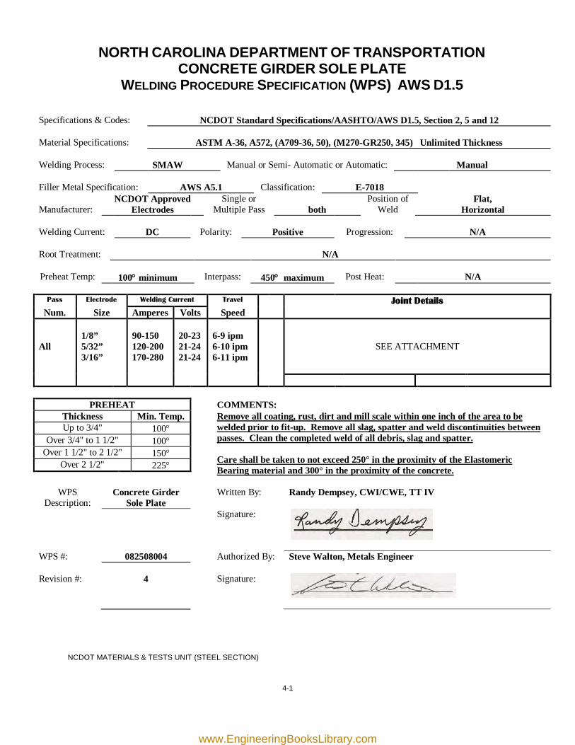
4-1
NORTH CAROLINA DEPARTMENT OF TRANSPORTATION CONCRETE GIRDER SOLE PLATE
WELDING PROCEDURE SPECIFICATION (WPS) AWS D1.5
Specifications & Codes:
NCDOT Standard Specifications/AASHTO/AWS D1.5, Section 2, 5 and 12
Material Specifications:
ASTM A-36, A572, (A709-36, 50), (M270-GR250, 345) Unlimited Thickness
Welding Process:
SMAW
Manual or Semi- Automatic or Automatic:
Manual
Filler Metal Specification:
AWS A5.1
Classification:
E-7018
Manufacturer:
NCDOT Approved Electrodes
Single or Multiple Pass
both
Position of Weld
Flat, Horizontal
Welding Current:
DC
Polarity:
Positive
Progression:
N/A
Root Treatment:
N/A
Preheat Temp:
100° minimum
Interpass:
450° maximum
Post Heat:
N/A
Pass Electrode Welding Current Travel Joint Details
Num. Size Amperes Volts Speed All
1/8” 5/32” 3/16”
90-150 120-200 170-280
20-23 21-24 21-24
6-9 ipm 6-10 ipm 6-11 ipm
SEE ATTACHMENT
PREHEAT COMMENTS: Thickness Min. Temp. Remove all coating, rust, dirt and mill scale within one inch of the area to be
welded prior to fit-up. Remove all slag, spatter and weld discontinuities between passes. Clean the completed weld of all debris, slag and spatter. Care shall be taken to not exceed 250° in the proximity of the Elastomeric Bearing material and 300° in the proximity of the concrete.
Up to 3/4" 100° Over 3/4" to 1 1/2" 100°
Over 1 1/2" to 2 1/2" 150° Over 2 1/2" 225°
WPS
Description: Concrete Girder
Sole Plate Written By: Randy Dempsey, CWI/CWE, TT IV
Signature:
WPS #: 082508004 Authorized By: Steve Walton, Metals Engineer Revision #:
4
Signature:
NCDOT MATERIALS & TESTS UNIT (STEEL SECTION)
www.EngineeringBooksLibrary.com
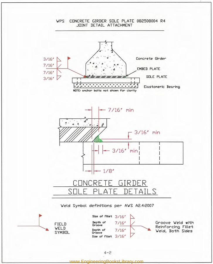
~PS CONCRETE GIRDER SOLE PLATE 082508004 R4JOINT DETAIL ATTACHMENT
Concrete Girder3/16"
7/16"
7/16#
3/16"
EMBED PLATE. 4' . SOLE PLATE
Elos+oner-lc BeorlngNOTE. o.nchor bolts not shown for clo.rlty
7/16" nln
•... [ 3/16"
I- 3/16" Min:I
1/8/1
CONCRETE GIRDERSOLE PLATE DETAILS
~elol SYMbol oIefinitions per A'WS A2.412007
-l Size of Fillet 3/16#
FIELD Depth of 7/16# Groove ~elol withGroove
~ELD Depth of 7/16#Reinforcing Fillet
SYMBOL Groove ~elol, Both Slde sSize of Fillet 3/16'
4-2
www.EngineeringBooksLibrary.com
4-3
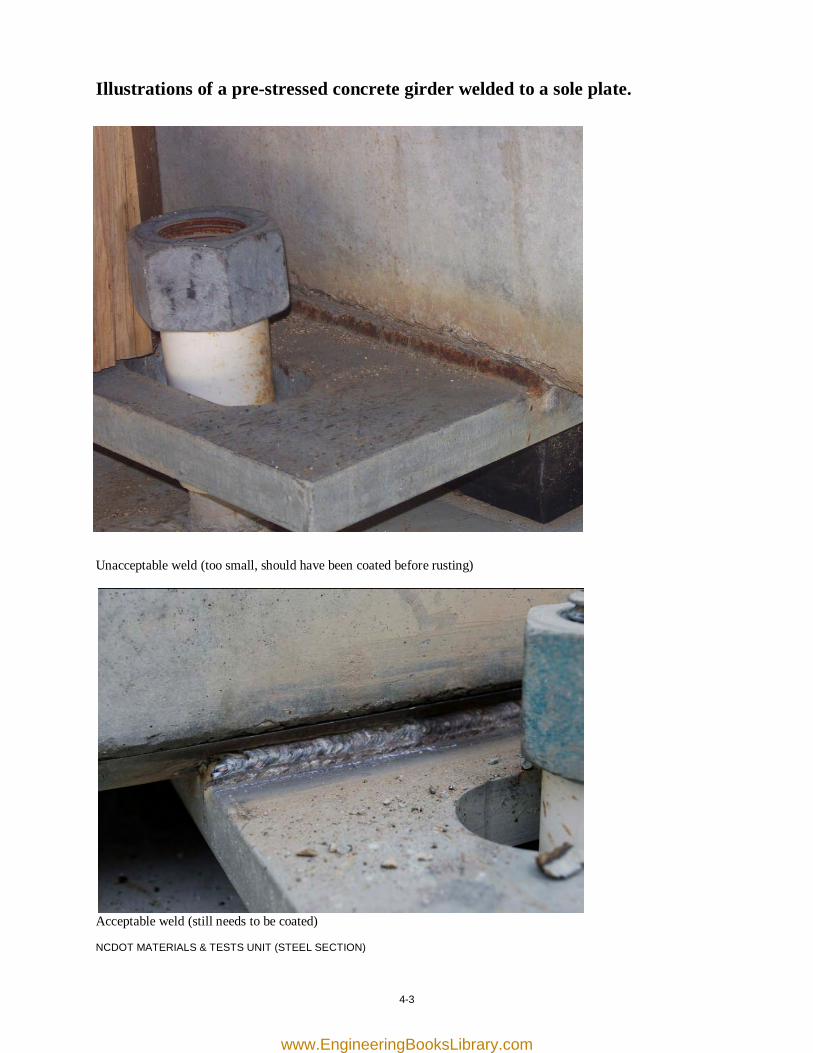
Illustrations of a pre-stressed concrete girder welded to a sole plate.
Unacceptable weld (too small, should have been coated before rusting)
Acceptable weld (still needs to be coated) NCDOT MATERIALS & TESTS UNIT (STEEL SECTION)
www.EngineeringBooksLibrary.com

[this page was intentionally left blank]
www.EngineeringBooksLibrary.com
5-1
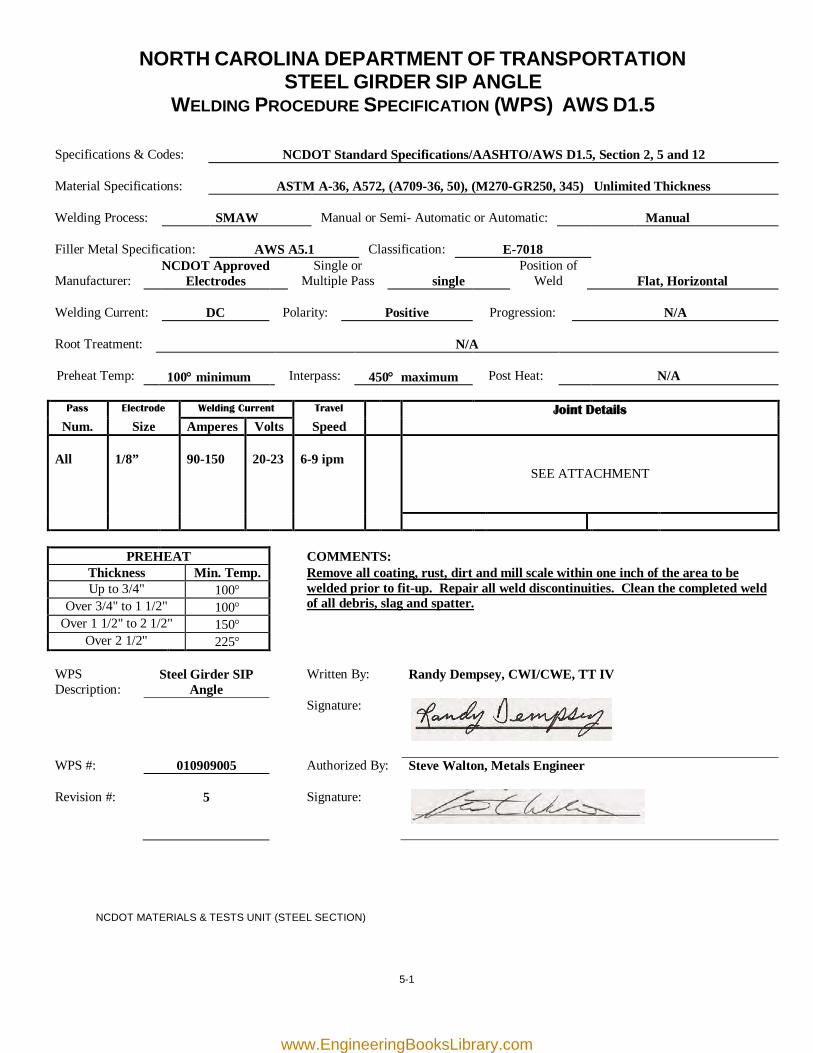
NORTH CAROLINA DEPARTMENT OF TRANSPORTATION STEEL GIRDER SIP ANGLE
WELDING PROCEDURE SPECIFICATION (WPS) AWS D1.5
Specifications & Codes:
NCDOT Standard Specifications/AASHTO/AWS D1.5, Section 2, 5 and 12
Material Specifications:
ASTM A-36, A572, (A709-36, 50), (M270-GR250, 345) Unlimited Thickness
Welding Process:
SMAW
Manual or Semi- Automatic or Automatic:
Manual
Filler Metal Specification:
AWS A5.1
Classification:
E-7018
Manufacturer:
NCDOT Approved Electrodes
Single or Multiple Pass
single
Position of Weld
Flat, Horizontal
Welding Current:
DC
Polarity:
Positive
Progression:
N/A
Root Treatment:
N/A
Preheat Temp:
100° minimum
Interpass:
450° maximum
Post Heat:
N/A
Pass Electrode Welding Current Travel Joint Details
Num. Size Amperes Volts Speed All
1/8”
90-150
20-23
6-9 ipm
SEE ATTACHMENT
PREHEAT COMMENTS: Thickness Min. Temp.
Remove all coating, rust, dirt and mill scale within one inch of the area to be welded prior to fit-up. Repair all weld discontinuities. Clean the completed weld of all debris, slag and spatter.
Up to 3/4" 100° Over 3/4" to 1 1/2" 100°
Over 1 1/2" to 2 1/2" 150° Over 2 1/2" 225°
WPS Description:
Steel Girder SIP Angle
Written By: Randy Dempsey, CWI/CWE, TT IV
Signature:
WPS #: 010909005 Authorized By: Steve Walton, Metals Engineer Revision #:
5
Signature:
NCDOT MATERIALS & TESTS UNIT (STEEL SECTION)
www.EngineeringBooksLibrary.com
o.s oIirecteoiby the plo.ns
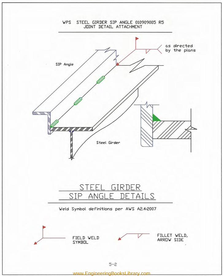
'WPS STEEL GIRDER SIP ANGLE 010909005 R5JOINT DETAIL ATTACHMENT
SIP Angle
Steel Girder
STEEL GIRDERSIP ANGLE DETAILS
'Welol SYMbol oIefinitions per A'WS A2.4:2007
v FILLET 'WELD,ARRO'W SIDEFIELD 'WELD
SYMBOL
5-2
www.EngineeringBooksLibrary.com
5-3
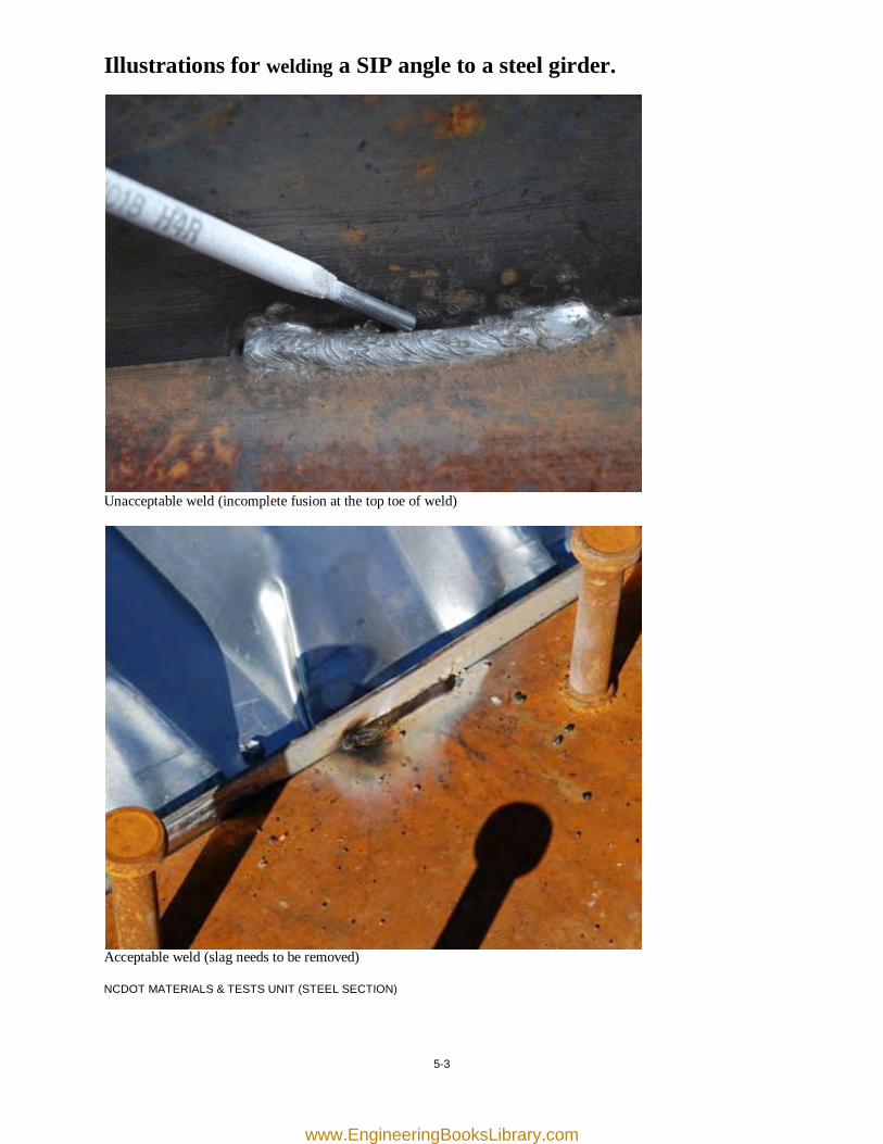
Illustrations for welding a SIP angle to a steel girder.
Unacceptable weld (incomplete fusion at the top toe of weld)
Acceptable weld (slag needs to be removed) NCDOT MATERIALS & TESTS UNIT (STEEL SECTION)
www.EngineeringBooksLibrary.com

[this page was intentionally left blank]
www.EngineeringBooksLibrary.com
6-1
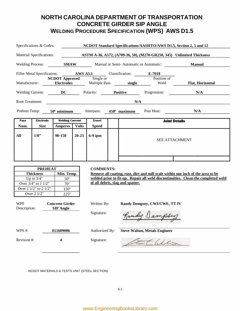
NORTH CAROLINA DEPARTMENT OF TRANSPORTATION CONCRETE GIRDER SIP ANGLE
WELDING PROCEDURE SPECIFICATION (WPS) AWS D1.5
Specifications & Codes:
NCDOT Standard Specifications/AASHTO/AWS D1.5, Section 2, 5 and 12
Material Specifications:
ASTM A-36, A572, (A709-36, 50), (M270-GR250, 345) Unlimited Thickness
Welding Process:
SMAW
Manual or Semi- Automatic or Automatic:
Manual
Filler Metal Specification:
AWS A5.1
Classification:
E-7018
Manufacturer:
NCDOT Approved Electrodes
Single or Multiple Pass
single
Position of Weld
Flat, Horizontal
Welding Current:
DC
Polarity:
Positive
Progression:
N/A
Root Treatment:
N/A
Preheat Temp:
50° minimum
Interpass:
450° maximum
Post Heat:
N/A
Pass Electrode Welding Current Travel Joint Details
Num. Size Amperes Volts Speed All
1/8”
90-150
20-23
6-9 ipm
SEE ATTACHMENT
PREHEAT COMMENTS: Thickness Min. Temp.
Remove all coating, rust, dirt and mill scale within one inch of the area to be welded prior to fit-up. Repair all weld discontinuities. Clean the completed weld of all debris, slag and spatter.
Up to 3/4" 50° Over 3/4" to 1 1/2" 70°
Over 1 1/2" to 2 1/2" 150° Over 2 1/2" 225°
WPS Description:
Concrete Girder SIP Angle
Written By: Randy Dempsey, CWI/CWE, TT IV
Signature:
WPS #: 011609006 Authorized By: Steve Walton, Metals Engineer Revision #:
4
Signature:
NCDOT MATERIALS & TESTS UNIT (STEEL SECTION)
www.EngineeringBooksLibrary.com
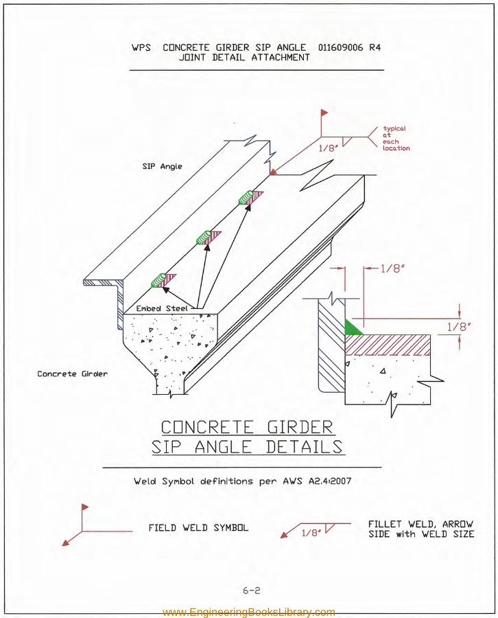
Concrete Girder
typlco.lo.teo.chloco.tlon
WlPS CONCRETE GIRDER SIP ANGLE 011609006 R4JOINT DETAIL ATTACHMENT
SIP Angle
CONCRETE GIRDERSIP ANGLE DETAILS
Wlelol SYMbol oIefinltions per AWlS A2.412007
~ FIELD WELD SYMBOL /118# V FILLET WIELD, ARROWISIDE with WIELD SIZE
6-2
www.EngineeringBooksLibrary.com
6-3
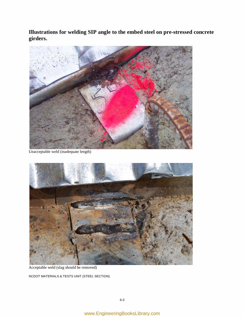
Illustrations for welding SIP angle to the embed steel on pre-stressed concrete girders.
Unacceptable weld (inadequate length)
Acceptable weld (slag should be removed) NCDOT MATERIALS & TESTS UNIT (STEEL SECTION)
www.EngineeringBooksLibrary.com

[this page was intentionally left blank]
www.EngineeringBooksLibrary.com
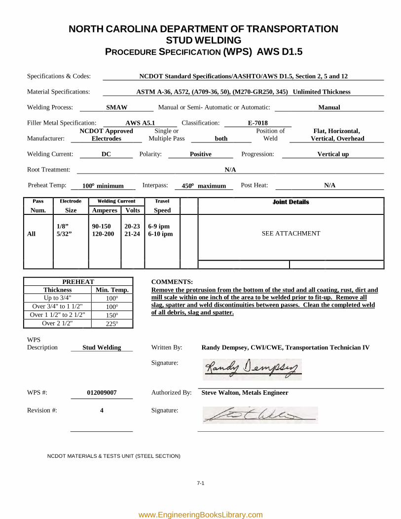
7-1
NORTH CAROLINA DEPARTMENT OF TRANSPORTATION STUD WELDING
PROCEDURE SPECIFICATION (WPS) AWS D1.5
Specifications & Codes:
NCDOT Standard Specifications/AASHTO/AWS D1.5, Section 2, 5 and 12
Material Specifications:
ASTM A-36, A572, (A709-36, 50), (M270-GR250, 345) Unlimited Thickness
Welding Process:
SMAW
Manual or Semi- Automatic or Automatic:
Manual
Filler Metal Specification:
AWS A5.1
Classification:
E-7018
Manufacturer:
NCDOT Approved Electrodes
Single or Multiple Pass
both
Position of Weld
Flat, Horizontal, Vertical, Overhead
Welding Current:
DC
Polarity:
Positive
Progression:
Vertical up
Root Treatment:
N/A
Preheat Temp:
100° minimum
Interpass:
450° maximum
Post Heat:
N/A
Pass Electrode Welding Current Travel Joint Details
Num. Size Amperes Volts Speed All
1/8” 5/32”
90-150 120-200
20-23 21-24
6-9 ipm 6-10 ipm
SEE ATTACHMENT
PREHEAT COMMENTS: Thickness Min. Temp. Remove the protrusion from the bottom of the stud and all coating, rust, dirt and
mill scale within one inch of the area to be welded prior to fit-up. Remove all slag, spatter and weld discontinuities between passes. Clean the completed weld of all debris, slag and spatter.
Up to 3/4" 100° Over 3/4" to 1 1/2" 100°
Over 1 1/2" to 2 1/2" 150° Over 2 1/2" 225°
WPS Description
Stud Welding
Written By:
Randy Dempsey, CWI/CWE, Transportation Technician IV
Signature:
WPS #: 012009007 Authorized By: Steve Walton, Metals Engineer Revision #:
4
Signature:
NCDOT MATERIALS & TESTS UNIT (STEEL SECTION)
www.EngineeringBooksLibrary.com
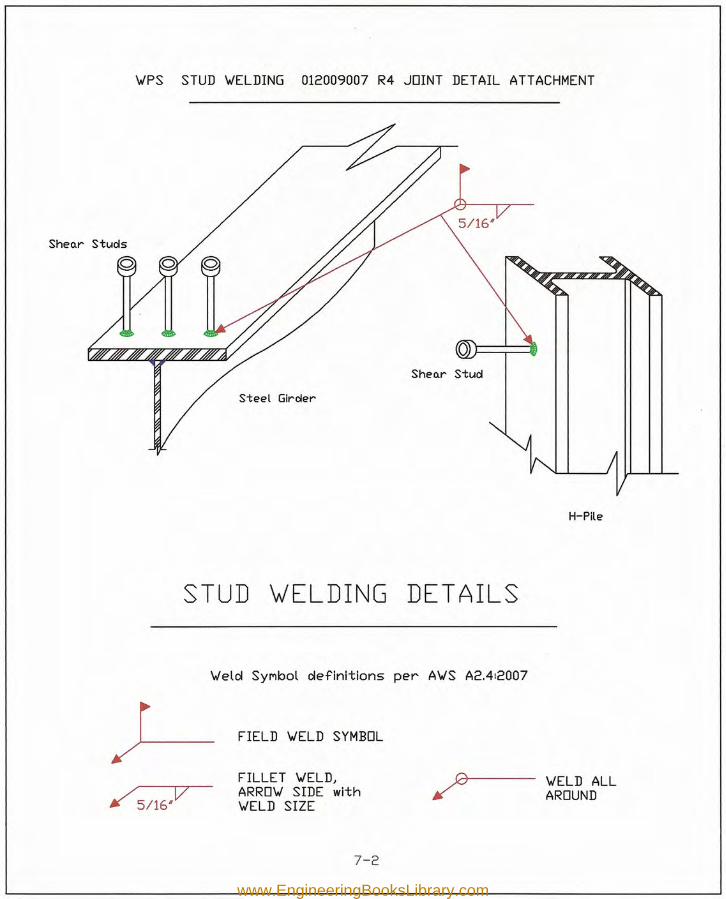
'WPS STUD 'WELDING 012009007 R4 JOINT DETAIL ATT ACHMENT
Sheo.r Stud
Steel Girder
H-Pile
STUD W'ELDING DETAILS
'Welol SYMbol oIefinitions per A'WS A2.412007
~ FIELD VELD SYMBOL
FILLET 'WELD,ARRO'W SIDE with'WELD SIZE
'WELD ALLAROUND
7-2
www.EngineeringBooksLibrary.com
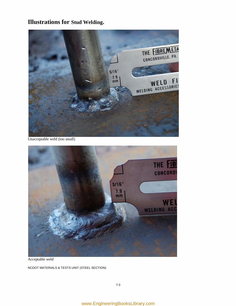
7-3
Illustrations for Stud Welding.
Unacceptable weld (too small)
Acceptable weld NCDOT MATERIALS & TESTS UNIT (STEEL SECTION)
www.EngineeringBooksLibrary.com

[this page was intentionally left blank]
www.EngineeringBooksLibrary.com
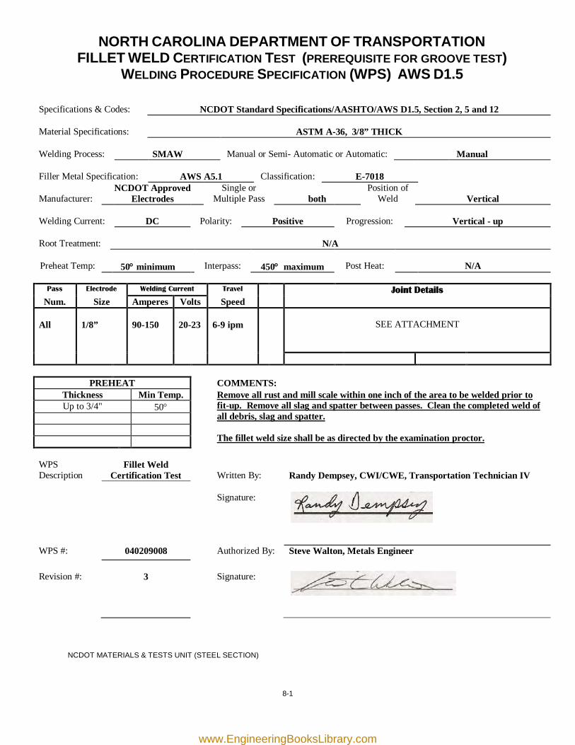
8-1
NORTH CAROLINA DEPARTMENT OF TRANSPORTATION FILLET WELD CERTIFICATION TEST (PREREQUISITE FOR GROOVE TEST)
WELDING PROCEDURE SPECIFICATION (WPS) AWS D1.5
Specifications & Codes:
NCDOT Standard Specifications/AASHTO/AWS D1.5, Section 2, 5 and 12
Material Specifications:
ASTM A-36, 3/8” THICK
Welding Process:
SMAW
Manual or Semi- Automatic or Automatic:
Manual
Filler Metal Specification:
AWS A5.1
Classification:
E-7018
Manufacturer:
NCDOT Approved Electrodes
Single or Multiple Pass
both
Position of Weld
Vertical
Welding Current:
DC
Polarity:
Positive
Progression:
Vertical - up
Root Treatment:
N/A
Preheat Temp:
50° minimum
Interpass:
450° maximum
Post Heat:
N/A
Pass Electrode Welding Current Travel Joint Details
Num. Size Amperes Volts Speed All
1/8”
90-150
20-23
6-9 ipm
SEE ATTACHMENT
PREHEAT COMMENTS: Thickness Min Temp. Remove all rust and mill scale within one inch of the area to be welded prior to
fit-up. Remove all slag and spatter between passes. Clean the completed weld of all debris, slag and spatter. The fillet weld size shall be as directed by the examination proctor.
Up to 3/4" 50°
WPS Description
Fillet Weld Certification Test
Written By:
Randy Dempsey, CWI/CWE, Transportation Technician IV
Signature:
WPS #: 040209008 Authorized By: Steve Walton, Metals Engineer Revision #:
3
Signature:
NCDOT MATERIALS & TESTS UNIT (STEEL SECTION)
www.EngineeringBooksLibrary.com
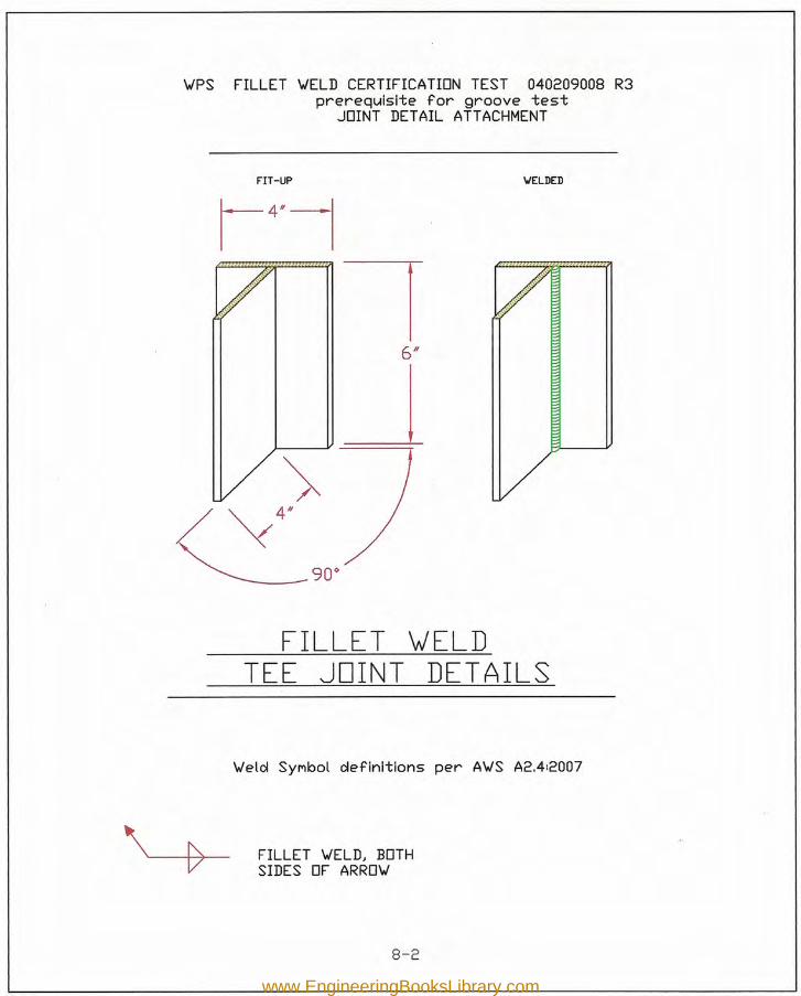
FIT-UP WELDED
\.JPS FILLET \.JELD CERTIFICATION TEST 040209008 R3pr-er-equlsl'te for groove test
JOINT DETAIL ATTACHMENT
90"---FILLET wELD
TEE JOINT DETAILS
\.Jelcl SYMbol clefinitions per A\.JS A2.4:2007
FILLET \.JELD, BOTHSIDES OF ARRO\.J
8-2
www.EngineeringBooksLibrary.com
8-3
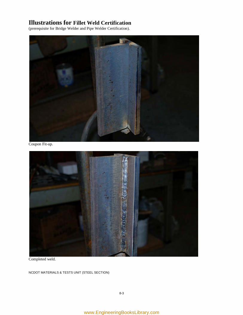
Illustrations for Fillet Weld Certification (prerequisite for Bridge Welder and Pipe Welder Certification).
Coupon Fit-up.
Completed weld. NCDOT MATERIALS & TESTS UNIT (STEEL SECTION)
www.EngineeringBooksLibrary.com

[this page was intentionally left blank]
www.EngineeringBooksLibrary.com
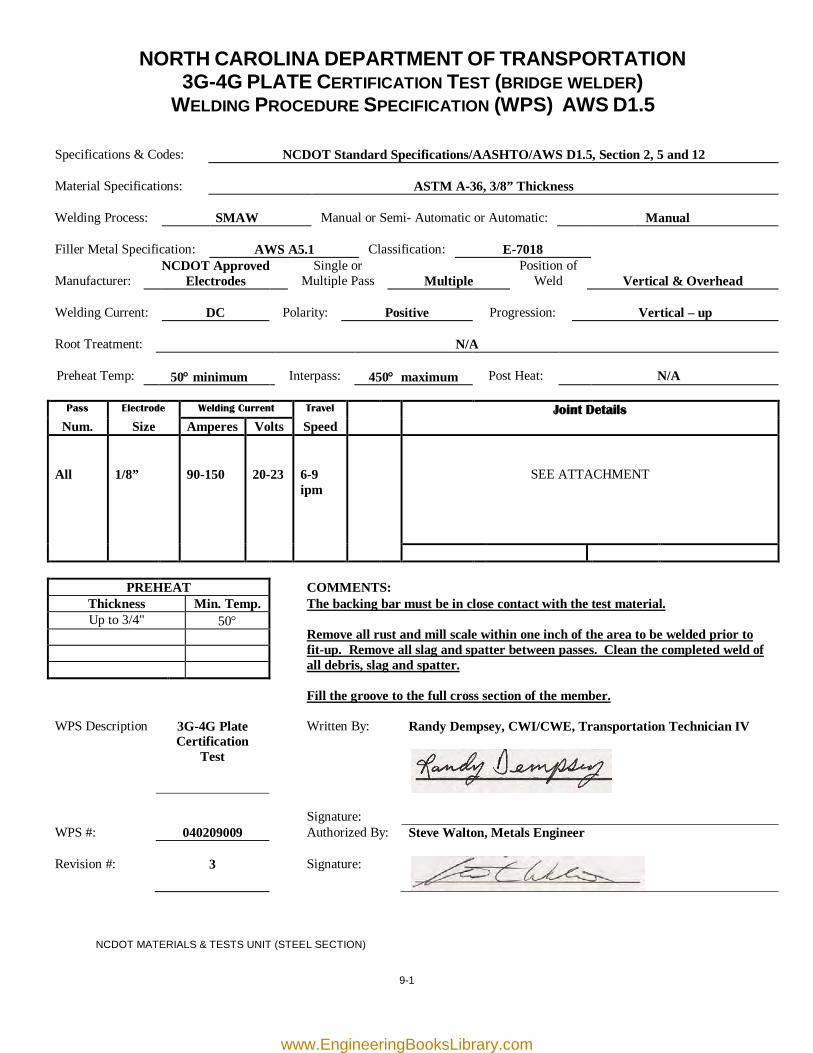
9-1
NORTH CAROLINA DEPARTMENT OF TRANSPORTATION 3G-4G PLATE CERTIFICATION TEST (BRIDGE WELDER)
WELDING PROCEDURE SPECIFICATION (WPS) AWS D1.5
Specifications & Codes:
NCDOT Standard Specifications/AASHTO/AWS D1.5, Section 2, 5 and 12
Material Specifications:
ASTM A-36, 3/8” Thickness
Welding Process:
SMAW
Manual or Semi- Automatic or Automatic:
Manual
Filler Metal Specification:
AWS A5.1
Classification:
E-7018
Manufacturer:
NCDOT Approved Electrodes
Single or Multiple Pass
Multiple
Position of Weld
Vertical & Overhead
Welding Current:
DC
Polarity:
Positive
Progression:
Vertical – up
Root Treatment:
N/A
Preheat Temp:
50° minimum
Interpass:
450° maximum
Post Heat:
N/A
Pass Electrode Welding Current Travel Joint Details
Num. Size Amperes Volts Speed All
1/8”
90-150
20-23
6-9 ipm
SEE ATTACHMENT
PREHEAT COMMENTS: Thickness Min. Temp. The backing bar must be in close contact with the test material.
Remove all rust and mill scale within one inch of the area to be welded prior to fit-up. Remove all slag and spatter between passes. Clean the completed weld of all debris, slag and spatter. Fill the groove to the full cross section of the member.
Up to 3/4" 50°
WPS Description 3G-4G Plate Certification
Test
Written By: Randy Dempsey, CWI/CWE, Transportation Technician IV
Signature:
WPS #: 040209009 Authorized By: Steve Walton, Metals Engineer Revision #:
3
Signature:
NCDOT MATERIALS & TESTS UNIT (STEEL SECTION)
www.EngineeringBooksLibrary.com

~PS 3G-4G PLATE CERTIFICATION TEST 040209009 R3JOINT DETAIL ATTACHMENT
4G Position
Equal
rtop &--r-1----- bot
f
3G Position
3G-4G GROOVE wELDJOINT DETAILS
~eld Synbol definitions per A~S A2.4:2007
BEVEL ~ELDJ ARRO~SIDE with BEVEL ANGLE8c ROOT OPENING
BACKINGBAR
9-2
www.EngineeringBooksLibrary.com
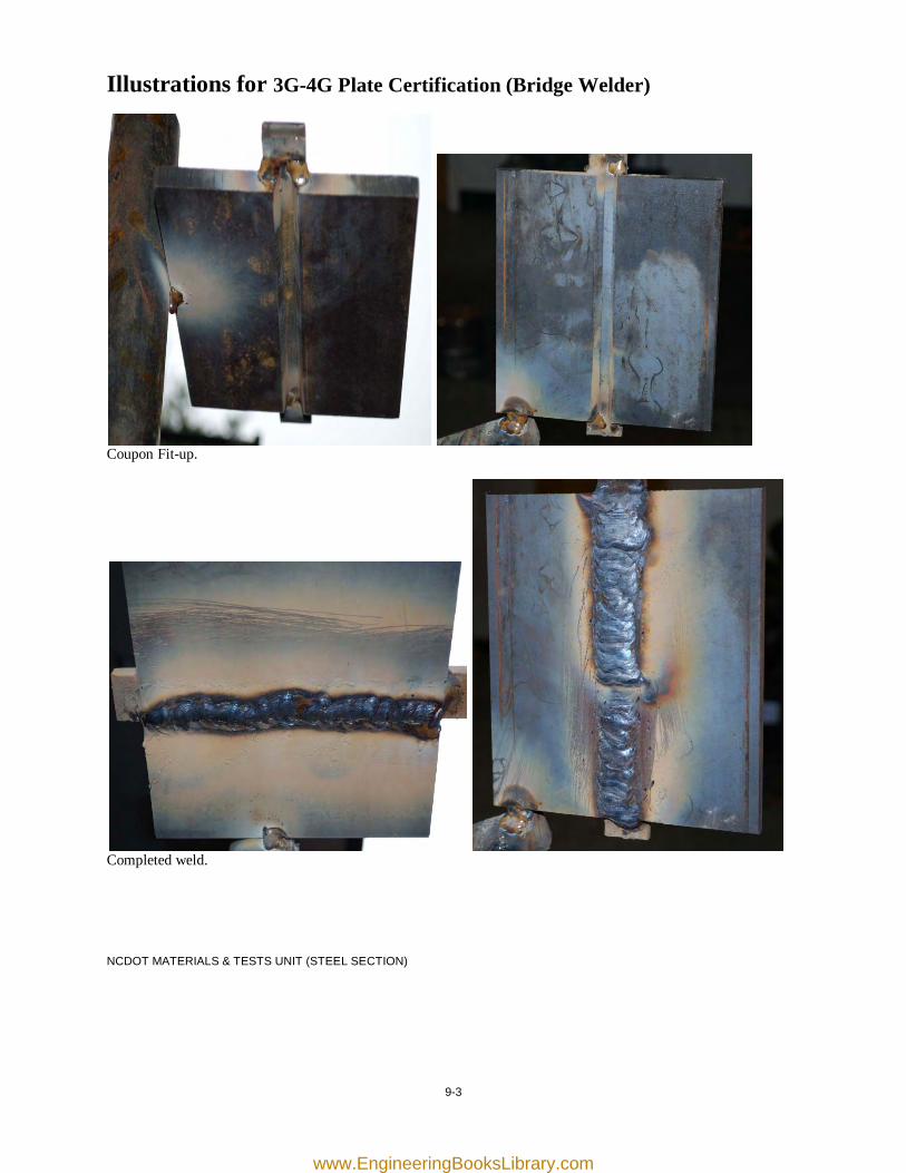
9-3
Illustrations for 3G-4G Plate Certification (Bridge Welder)
Coupon Fit-up.
Completed weld. NCDOT MATERIALS & TESTS UNIT (STEEL SECTION)
www.EngineeringBooksLibrary.com

[this page was intentionally left blank]
www.EngineeringBooksLibrary.com
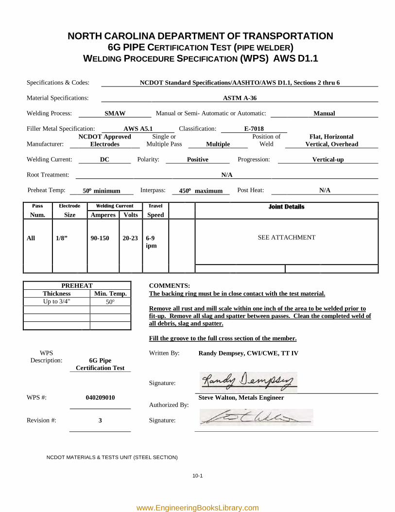
10-1
NORTH CAROLINA DEPARTMENT OF TRANSPORTATION 6G PIPE CERTIFICATION TEST (PIPE WELDER)
WELDING PROCEDURE SPECIFICATION (WPS) AWS D1.1
Specifications & Codes:
NCDOT Standard Specifications/AASHTO/AWS D1.1, Sections 2 thru 6
Material Specifications:
ASTM A-36
Welding Process:
SMAW
Manual or Semi- Automatic or Automatic:
Manual
Filler Metal Specification:
AWS A5.1
Classification:
E-7018
Manufacturer:
NCDOT Approved Electrodes
Single or Multiple Pass
Multiple
Position of Weld
Flat, Horizontal Vertical, Overhead
Welding Current:
DC
Polarity:
Positive
Progression:
Vertical-up
Root Treatment:
N/A
Preheat Temp:
50° minimum
Interpass:
450° maximum
Post Heat:
N/A
Pass Electrode Welding Current Travel Joint Details
Num. Size Amperes Volts Speed All
1/8”
90-150
20-23
6-9 ipm
SEE ATTACHMENT
PREHEAT COMMENTS: Thickness Min. Temp. The backing ring must be in close contact with the test material.
Remove all rust and mill scale within one inch of the area to be welded prior to fit-up. Remove all slag and spatter between passes. Clean the completed weld of all debris, slag and spatter. Fill the groove to the full cross section of the member.
Up to 3/4" 50°
WPS Description:
6G Pipe
Certification Test
Written By: Randy Dempsey, CWI/CWE, TT IV
Signature:
WPS #: 040209010
Authorized By: Steve Walton, Metals Engineer
Revision #:
3
Signature:
NCDOT MATERIALS & TESTS UNIT (STEEL SECTION)
www.EngineeringBooksLibrary.com
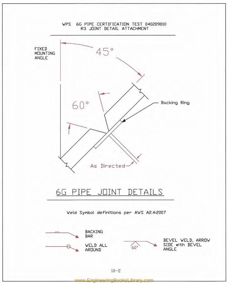
'w'PS 6G PIPE CERTIFICATION TEST 040209010R3 JOINT DETAIL ATTACHMENT
FIXED 45<>MOUNTINGANGLE
As Directeol
6G PIPE JOINT DET AILS
Bo.cking Ring
'w'eld SYMbol definitions per A'w'S A2.4:2007
BACKINGBAR
'w'ELD ALLAROUND
10-2
BEVEL 'w'ELD, ARRO'w'SIDE with BEVELANGLE
www.EngineeringBooksLibrary.com
10-3
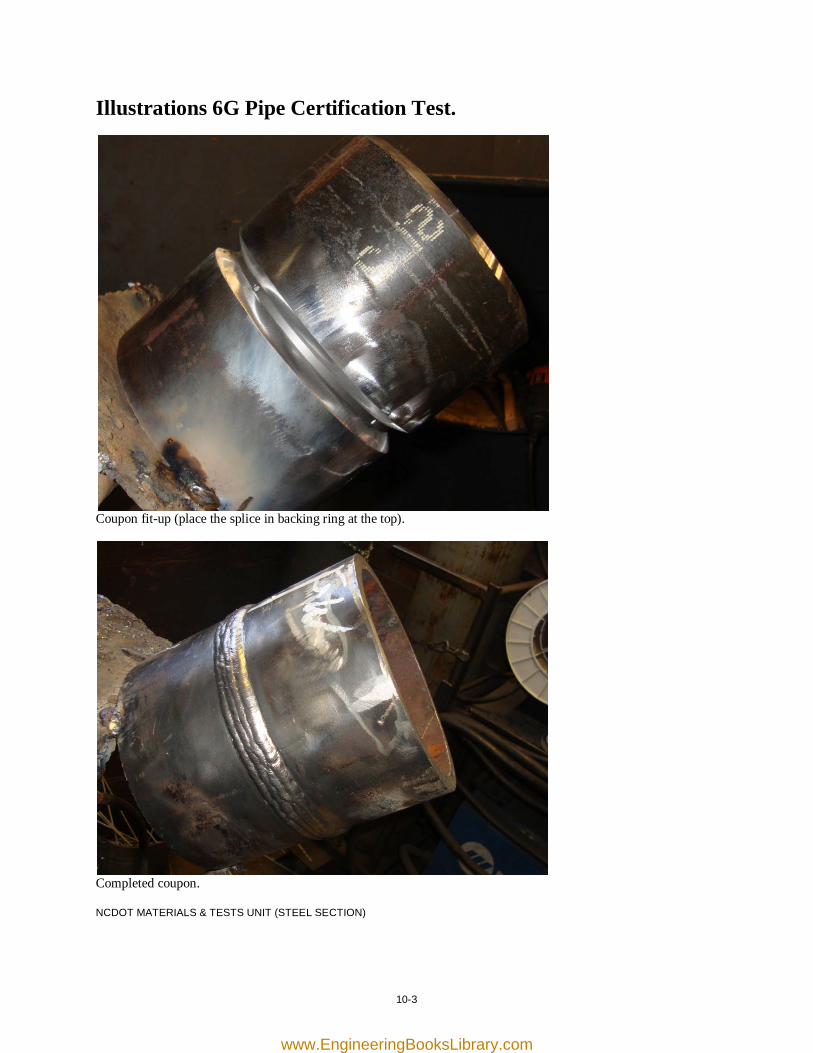
Illustrations 6G Pipe Certification Test.
Coupon fit-up (place the splice in backing ring at the top).
Completed coupon. NCDOT MATERIALS & TESTS UNIT (STEEL SECTION)
www.EngineeringBooksLibrary.com

[this page was intentionally left blank]
www.EngineeringBooksLibrary.com
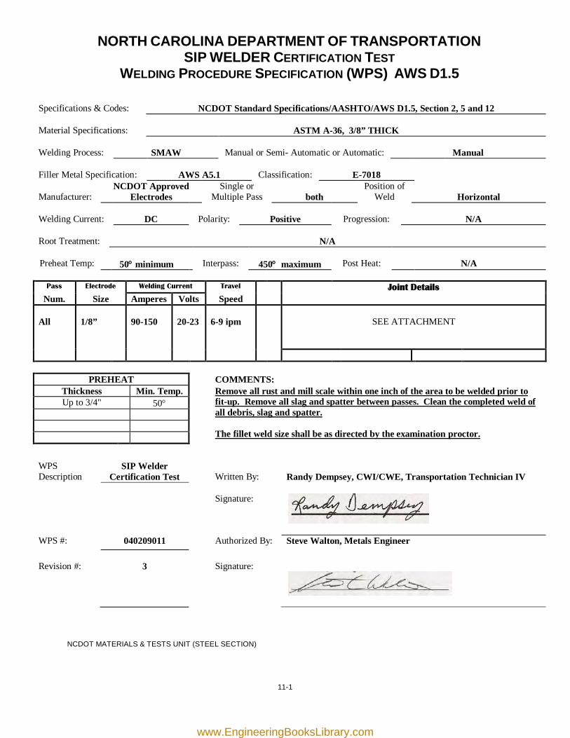
11-1
NORTH CAROLINA DEPARTMENT OF TRANSPORTATION SIP WELDER CERTIFICATION TEST
WELDING PROCEDURE SPECIFICATION (WPS) AWS D1.5
Specifications & Codes:
NCDOT Standard Specifications/AASHTO/AWS D1.5, Section 2, 5 and 12
Material Specifications:
ASTM A-36, 3/8” THICK
Welding Process:
SMAW
Manual or Semi- Automatic or Automatic:
Manual
Filler Metal Specification:
AWS A5.1
Classification:
E-7018
Manufacturer:
NCDOT Approved Electrodes
Single or Multiple Pass
both
Position of Weld
Horizontal
Welding Current:
DC
Polarity:
Positive
Progression:
N/A
Root Treatment:
N/A
Preheat Temp:
50° minimum
Interpass:
450° maximum
Post Heat:
N/A
Pass Electrode Welding Current Travel Joint Details
Num. Size Amperes Volts Speed All
1/8”
90-150
20-23
6-9 ipm
SEE ATTACHMENT
PREHEAT COMMENTS: Thickness Min. Temp. Remove all rust and mill scale within one inch of the area to be welded prior to
fit-up. Remove all slag and spatter between passes. Clean the completed weld of all debris, slag and spatter. The fillet weld size shall be as directed by the examination proctor.
Up to 3/4" 50°
WPS Description
SIP Welder Certification Test
Written By:
Randy Dempsey, CWI/CWE, Transportation Technician IV
Signature:
WPS #: 040209011 Authorized By: Steve Walton, Metals Engineer Revision #:
3
Signature:
NCDOT MATERIALS & TESTS UNIT (STEEL SECTION)
www.EngineeringBooksLibrary.com
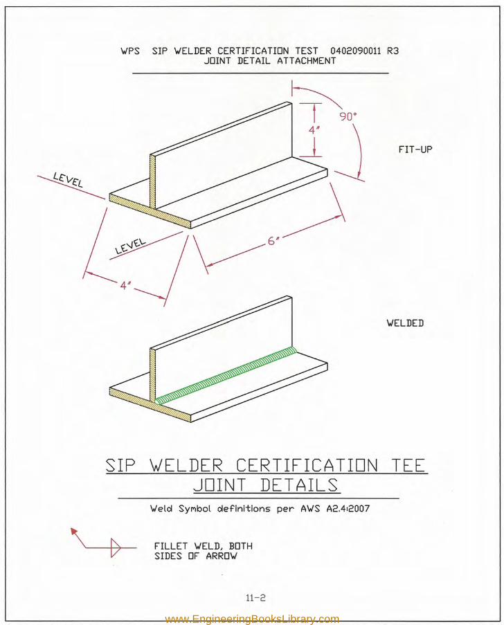
SIP \JELDER CERTIFICATION TEEJOINT DET AILS
'WPS SIP 'WELDER CERTIFICA TION TEST 0402090011 R3JOINT DETAIL ATTACHMENT
'Weld SYMbol definitions per A'WS A2.4:2007
FILLET 'WELD, BOTHSIDES OF ARRO'W
11-2
FIT-UP
'WELDED
www.EngineeringBooksLibrary.com
11-3
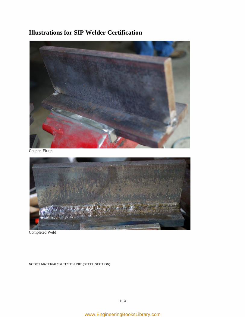
Illustrations for SIP Welder Certification
Coupon Fit-up
Completed Weld NCDOT MATERIALS & TESTS UNIT (STEEL SECTION)
www.EngineeringBooksLibrary.com

[this page was intentionally left blank]
www.EngineeringBooksLibrary.com

12-1
NORTH CAROLINA DEPARTMENT OF TRANSPORTATION ENCASEMENT PIPE
WELDING PROCEDURE SPECIFICATION (WPS) AWS D1.1
Specifications & Codes:
NCDOT Standard Specifications/AASHTO/AWS D1.1, Sections 2 thru 6
Material Specifications:
ASTM A-36, A572, (A709-36, 50), (M270-GR250, 345) Unlimited Thickness
Welding Process:
SMAW
Manual or Semi- Automatic or Automatic:
Manual
Filler Metal Specification:
AWS A5.1
Classification:
E-7018
Manufacturer:
NCDOT Approved Electrodes
Single or Multiple Pass
both
Position of Weld
Flat, Horizontal, Vertical, Overhead
Welding Current:
DC
Polarity:
Positive
Progression:
N/A
Root Treatment:
N/A
Preheat Temp:
100° minimum
Interpass:
450° maximum
Post Heat:
N/A
Pass Electrode Welding Current Travel Joint Details
Num. Size Amperes Volts Speed All
1/8” 5/32"
90-150 120-200
20-23 21-24
6-9 ipm 6-10 ipm
SEE ATTACHMENT
PREHEAT COMMENTS: Thickness Min. Temp. Remove all coating, rust, dirt and mill scale within one inch of the area to be
welded prior to fit-up. Remove all slag, spatter and weld discontinuities between passes. Clean the completed weld of all debris, slag and spatter.
Up to 3/4" 100° Over 3/4" to 1 1/2" 100°
Over 1 1/2" to 2 1/2" 150° Over 2 1/2" 225°
WPS
Description:
Encasement-Pipe Written By: Randy Dempsey, CWI/CWE, TT IV
Signature:
WPS #: 081109012 Authorized By: Steve Walton, Metals Engineer Revision #:
3
Signature:
NCDOT MATERIALS & TESTS UNIT (STEEL SECTION)
www.EngineeringBooksLibrary.com
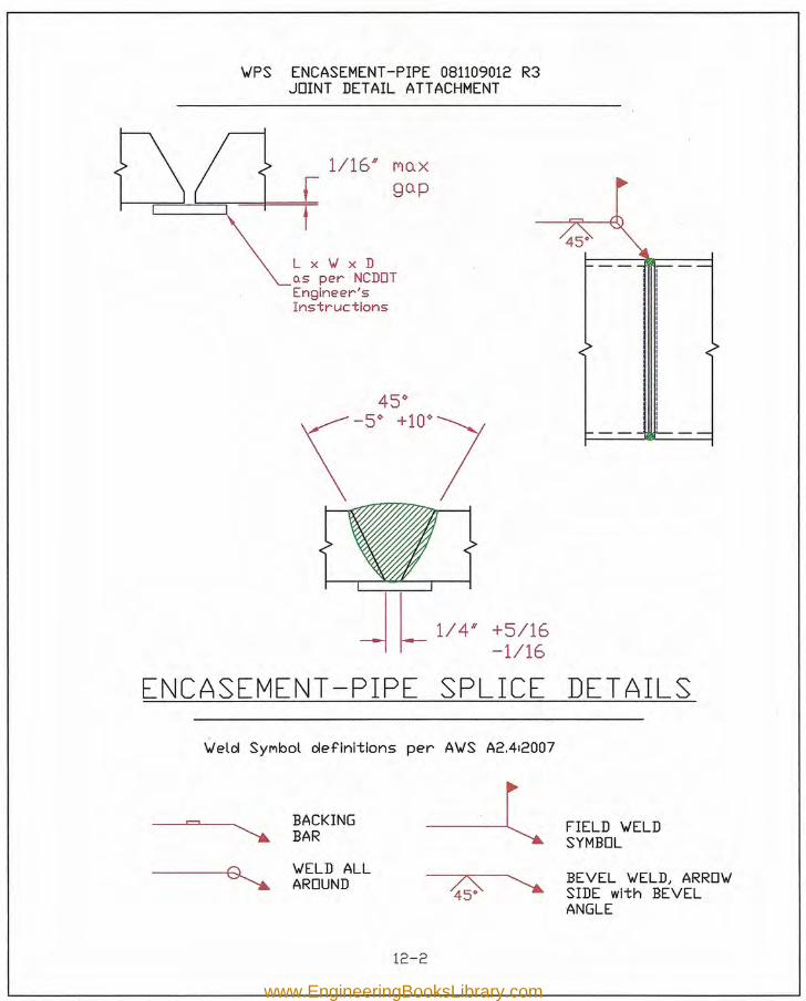
\vPS ENCASEMENT -PIPE 081109012 R3JOINT DETAIL ATTACHMENT
I I 1/4" +5/16-11- -1/16
ENCASEMENT-PIPE SPLICE DETAILS\Velcl Synbol clefinitions per A\vS A2.4:2007
1/16" I"'lo.xgo.p
Lx\JxDo.s per NCDOTEngineer'sInstructions
BACKINGBAR
\VELD ALLAROUND
12-2
FIELD \VELDSYMBOL
BEVEL \VELD, ARRO\vSIDE with BEVELANGLE
www.EngineeringBooksLibrary.com
12-3
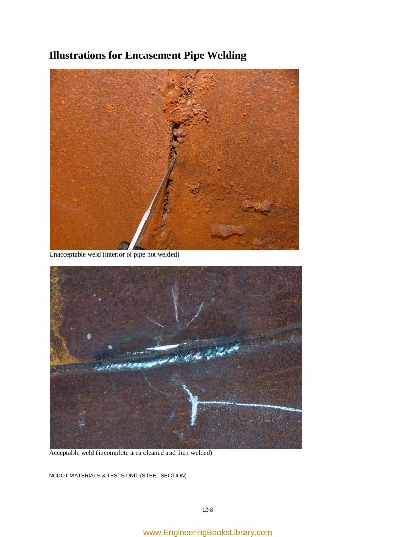
Illustrations for Encasement Pipe Welding
Unacceptable weld (interior of pipe not welded)
Acceptable weld (incomplete area cleaned and then welded) NCDOT MATERIALS & TESTS UNIT (STEEL SECTION)
www.EngineeringBooksLibrary.com

[this page was intentionally left blank]
www.EngineeringBooksLibrary.com
13-1
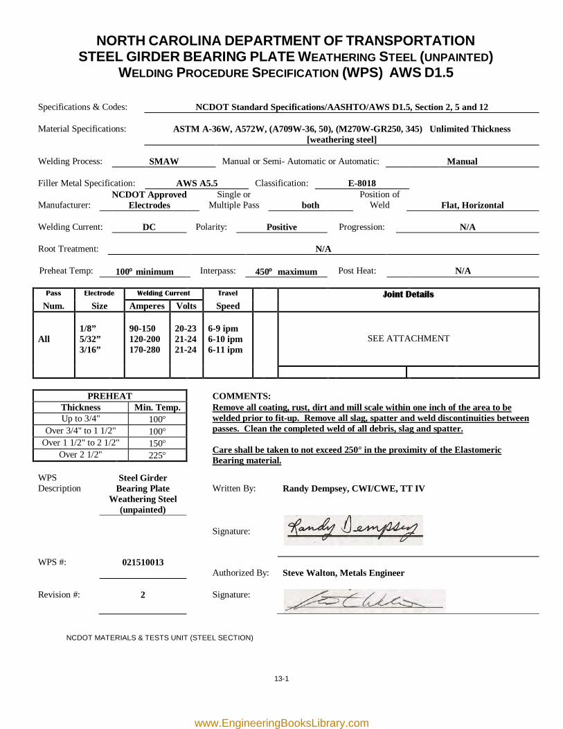
NORTH CAROLINA DEPARTMENT OF TRANSPORTATION STEEL GIRDER BEARING PLATE WEATHERING STEEL (UNPAINTED)
WELDING PROCEDURE SPECIFICATION (WPS) AWS D1.5
Specifications & Codes:
NCDOT Standard Specifications/AASHTO/AWS D1.5, Section 2, 5 and 12
Material Specifications:
ASTM A-36W, A572W, (A709W-36, 50), (M270W-GR250, 345) Unlimited Thickness
[weathering steel] Welding Process:
SMAW
Manual or Semi- Automatic or Automatic:
Manual
Filler Metal Specification:
AWS A5.5
Classification:
E-8018
Manufacturer:
NCDOT Approved Electrodes
Single or Multiple Pass
both
Position of Weld
Flat, Horizontal
Welding Current:
DC
Polarity:
Positive
Progression:
N/A
Root Treatment:
N/A
Preheat Temp:
100° minimum
Interpass:
450° maximum
Post Heat:
N/A
Pass Electrode Welding Current Travel Joint Details
Num. Size Amperes Volts Speed All
1/8” 5/32” 3/16”
90-150 120-200 170-280
20-23 21-24 21-24
6-9 ipm 6-10 ipm 6-11 ipm
SEE ATTACHMENT
PREHEAT COMMENTS: Thickness Min. Temp. Remove all coating, rust, dirt and mill scale within one inch of the area to be
welded prior to fit-up. Remove all slag, spatter and weld discontinuities between passes. Clean the completed weld of all debris, slag and spatter. Care shall be taken to not exceed 250° in the proximity of the Elastomeric Bearing material.
Up to 3/4" 100° Over 3/4" to 1 1/2" 100°
Over 1 1/2" to 2 1/2" 150° Over 2 1/2" 225°
WPS Description
Steel Girder Bearing Plate
Weathering Steel (unpainted)
Written By:
Randy Dempsey, CWI/CWE, TT IV
Signature:
WPS #: 021510013 Authorized By:
Steve Walton, Metals Engineer
Revision #:
2
Signature:
NCDOT MATERIALS & TESTS UNIT (STEEL SECTION)
www.EngineeringBooksLibrary.com
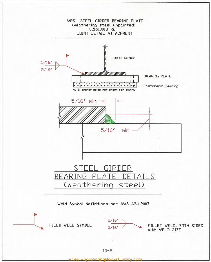
~PS .STEEL GIRDER BEARING PLATE(wen thering steel-unpnintecD
021510013 R2JOINT DETAIL ATTACHMENT
5/16'
5/16*
Steel Girder
BEARING PLATE
ElastoMerlc BearingNOTE.nnc:hor bolts not shown for c:lnrlty
5/16" Min
STEEL GIRDERBEARING PLATE DETAILS
(wenthering steel)
~eld SYMbol definitions per A~S A2.4:2007
FIELD ~ELD SYMBOL5~5/16' V ~ FILLET ~ELDJ BOTH SIDES
with ~ELD SIZE
13-2
www.EngineeringBooksLibrary.com
13-3
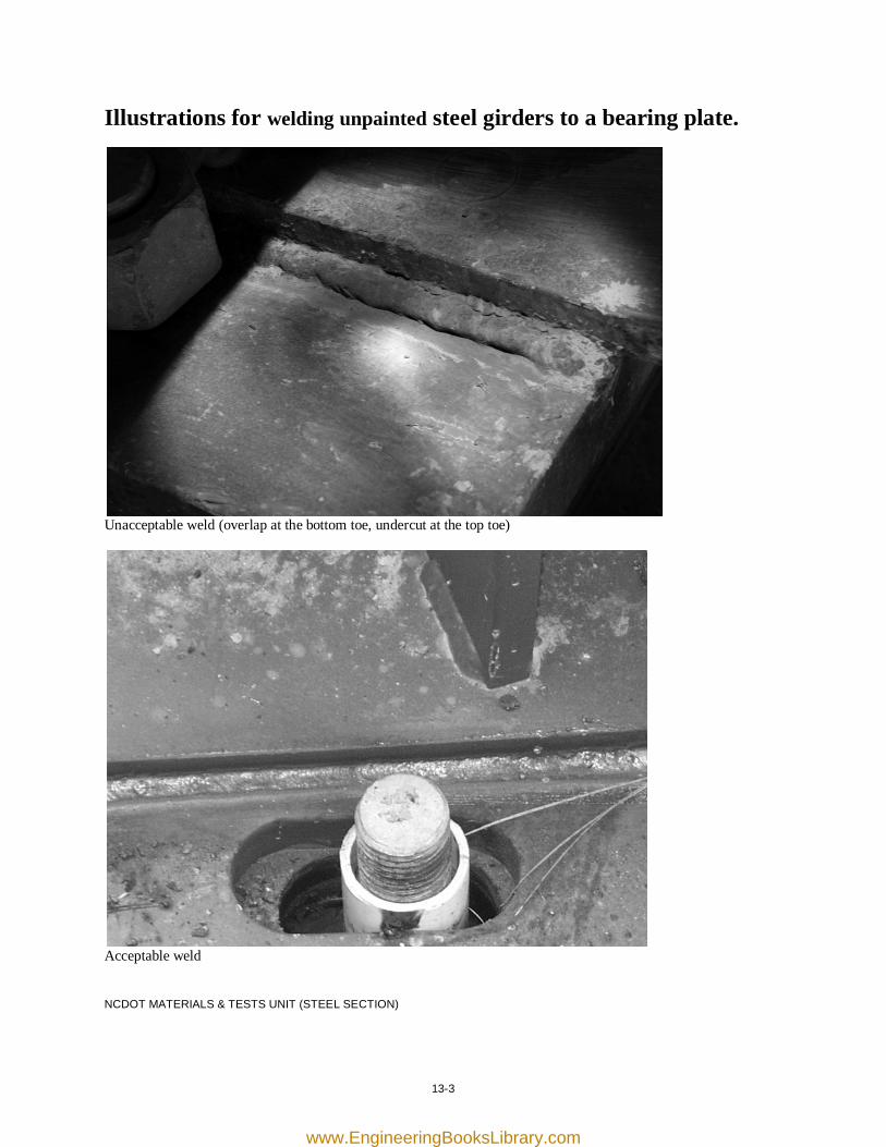
Illustrations for welding unpainted steel girders to a bearing plate.
Unacceptable weld (overlap at the bottom toe, undercut at the top toe)
Acceptable weld NCDOT MATERIALS & TESTS UNIT (STEEL SECTION)
www.EngineeringBooksLibrary.com

[this page was intentionally left blank]
www.EngineeringBooksLibrary.com
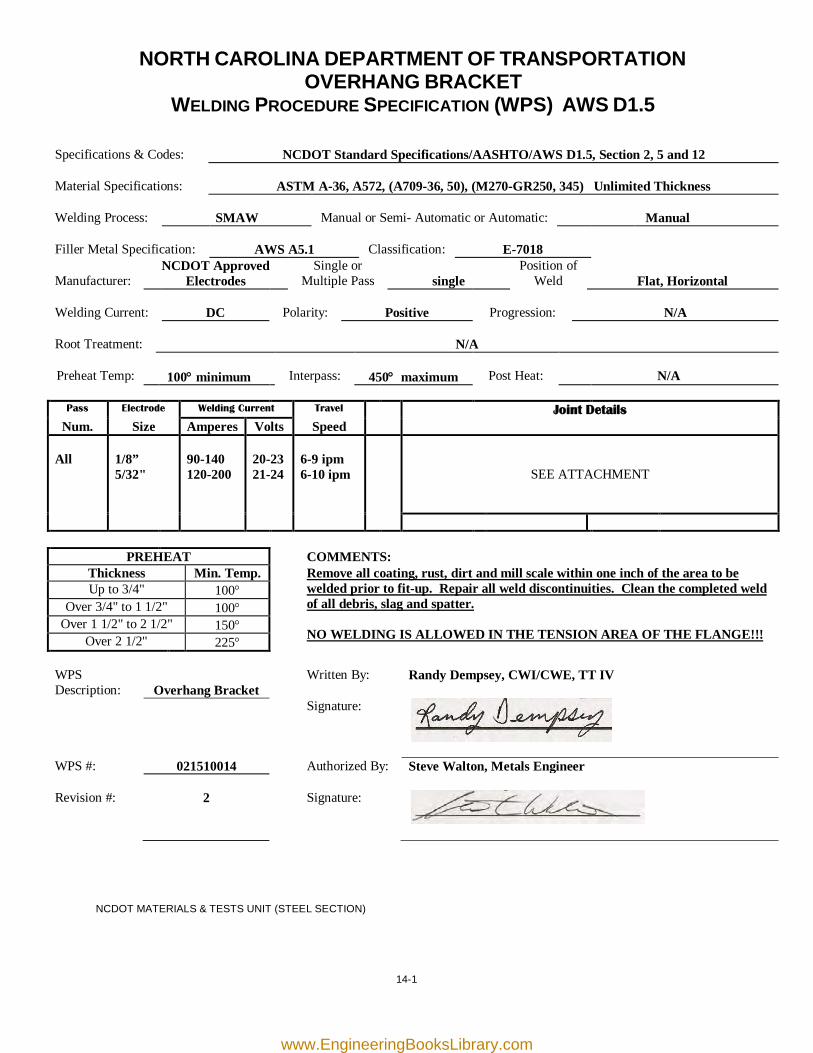
14-1
NORTH CAROLINA DEPARTMENT OF TRANSPORTATION OVERHANG BRACKET
WELDING PROCEDURE SPECIFICATION (WPS) AWS D1.5
Specifications & Codes:
NCDOT Standard Specifications/AASHTO/AWS D1.5, Section 2, 5 and 12
Material Specifications:
ASTM A-36, A572, (A709-36, 50), (M270-GR250, 345) Unlimited Thickness
Welding Process:
SMAW
Manual or Semi- Automatic or Automatic:
Manual
Filler Metal Specification:
AWS A5.1
Classification:
E-7018
Manufacturer:
NCDOT Approved Electrodes
Single or Multiple Pass
single
Position of Weld
Flat, Horizontal
Welding Current:
DC
Polarity:
Positive
Progression:
N/A
Root Treatment:
N/A
Preheat Temp:
100° minimum
Interpass:
450° maximum
Post Heat:
N/A
Pass Electrode Welding Current Travel Joint Details
Num. Size Amperes Volts Speed All
1/8” 5/32"
90-140 120-200
20-23 21-24
6-9 ipm 6-10 ipm
SEE ATTACHMENT
PREHEAT COMMENTS: Thickness Min. Temp.
Remove all coating, rust, dirt and mill scale within one inch of the area to be welded prior to fit-up. Repair all weld discontinuities. Clean the completed weld of all debris, slag and spatter.
NO WELDING IS ALLOWED IN THE TENSION AREA OF THE FLANGE!!!
Up to 3/4" 100° Over 3/4" to 1 1/2" 100°
Over 1 1/2" to 2 1/2" 150° Over 2 1/2" 225°
WPS Description:
Overhang Bracket
Written By: Randy Dempsey, CWI/CWE, TT IV
Signature:
WPS #: 021510014 Authorized By: Steve Walton, Metals Engineer Revision #:
2
Signature:
NCDOT MATERIALS & TESTS UNIT (STEEL SECTION)
www.EngineeringBooksLibrary.com
1114>
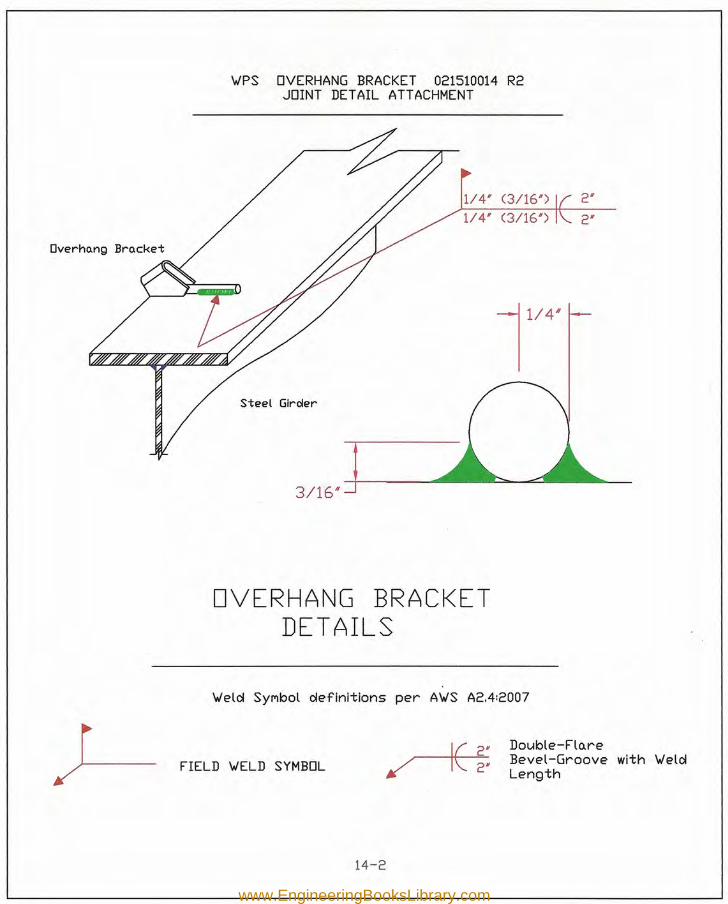
\.IPS OVERHANG BRACKET 021510014 R2JOINT DETAIL ATTACHMENT
114' (3/161) 2'
114' (3/161) 2'
Steel Glrc/er
3/16'"
OVERHANG BRACKETDETAILS
\.Ielcl SYMbol clefinitions per A\.IS A2.4:2007
FIELD \.IELD SYMBOL~/ I\.. 2'
Double-Fla.reBevel-Groove with \.IelclLength
14-2
www.EngineeringBooksLibrary.com
14-3
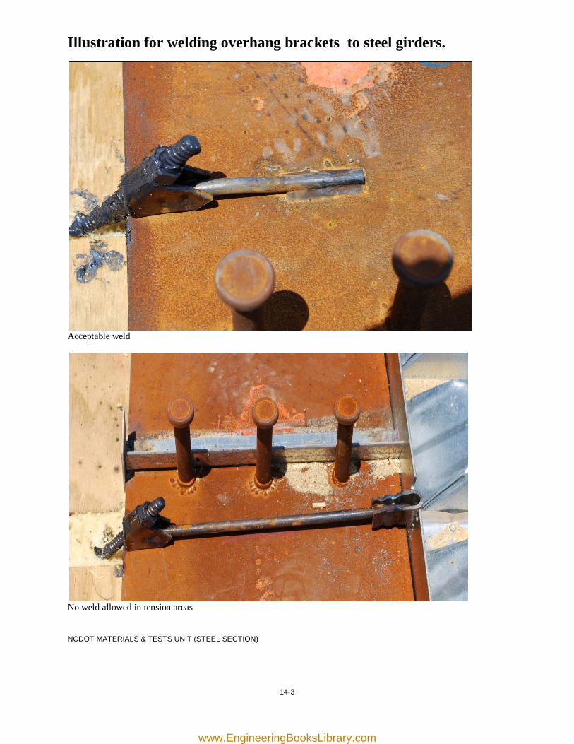
Illustration for welding overhang brackets to steel girders.
Acceptable weld
No weld allowed in tension areas NCDOT MATERIALS & TESTS UNIT (STEEL SECTION)
www.EngineeringBooksLibrary.com

[this page was intentionally left blank]
www.EngineeringBooksLibrary.com
15-1
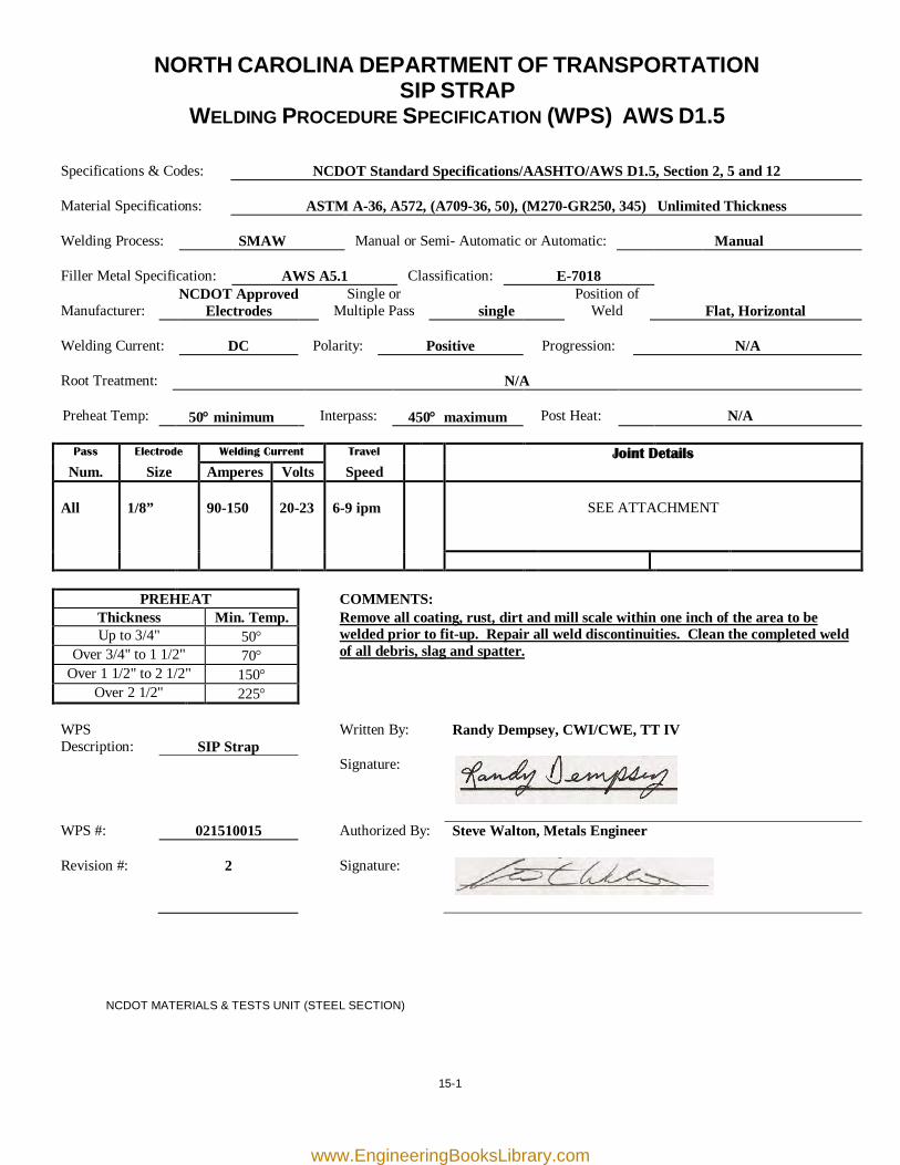
NORTH CAROLINA DEPARTMENT OF TRANSPORTATION SIP STRAP
WELDING PROCEDURE SPECIFICATION (WPS) AWS D1.5
Specifications & Codes:
NCDOT Standard Specifications/AASHTO/AWS D1.5, Section 2, 5 and 12
Material Specifications:
ASTM A-36, A572, (A709-36, 50), (M270-GR250, 345) Unlimited Thickness
Welding Process:
SMAW
Manual or Semi- Automatic or Automatic:
Manual
Filler Metal Specification:
AWS A5.1
Classification:
E-7018
Manufacturer:
NCDOT Approved Electrodes
Single or Multiple Pass
single
Position of Weld
Flat, Horizontal
Welding Current:
DC
Polarity:
Positive
Progression:
N/A
Root Treatment:
N/A
Preheat Temp:
50° minimum
Interpass:
450° maximum
Post Heat:
N/A
Pass Electrode Welding Current Travel Joint Details
Num. Size Amperes Volts Speed All
1/8”
90-150
20-23
6-9 ipm
SEE ATTACHMENT
PREHEAT COMMENTS: Thickness Min. Temp.
Remove all coating, rust, dirt and mill scale within one inch of the area to be welded prior to fit-up. Repair all weld discontinuities. Clean the completed weld of all debris, slag and spatter.
Up to 3/4" 50° Over 3/4" to 1 1/2" 70°
Over 1 1/2" to 2 1/2" 150° Over 2 1/2" 225°
WPS Description:
SIP Strap
Written By: Randy Dempsey, CWI/CWE, TT IV
Signature:
WPS #: 021510015 Authorized By: Steve Walton, Metals Engineer Revision #:
2
Signature:
NCDOT MATERIALS & TESTS UNIT (STEEL SECTION)
www.EngineeringBooksLibrary.com
o.s oIlrecteolby the plo.ns
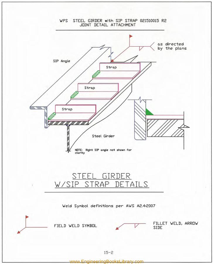
v=s STEEL GIRDER with SIP STRAP 021510015 R2JOINT DETAIL ATTACHMENT
SIP Angle
Steel Gircler
NOTEI Right SIP o.ngle not shown fordo.rlty
STEEL GIRDERVI /SIP STRAP DETAILS
'vielol SYMbol oIefinitions per A'vIS A2.4:2007
J-- FIELD IJELD SYMBOL v FILLET 'vIELD, ARRO'vlSIDE
15-2
www.EngineeringBooksLibrary.com
15-3
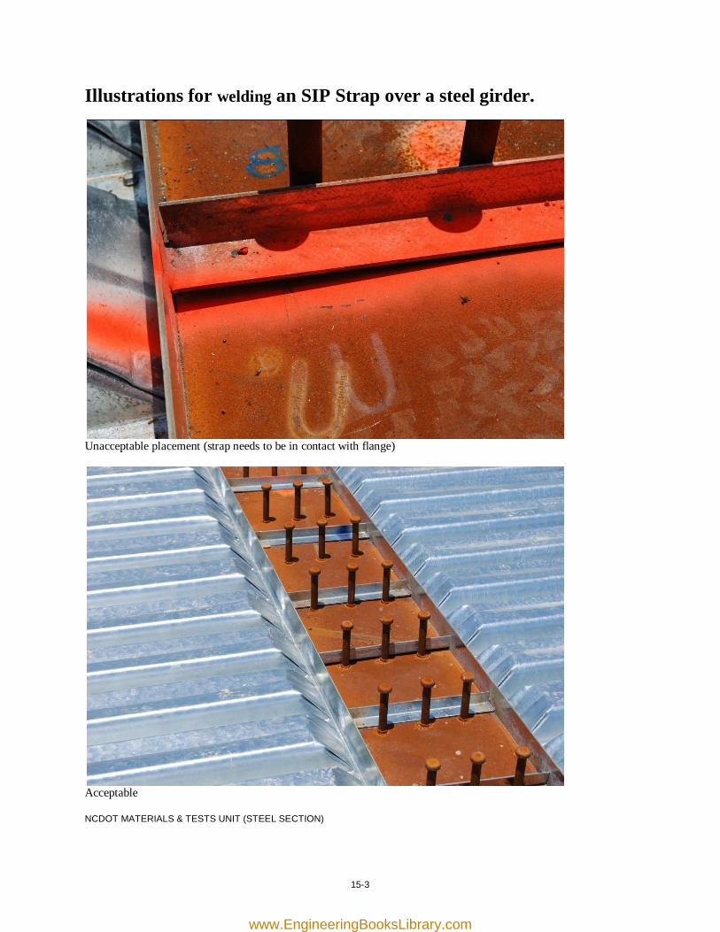
Illustrations for welding an SIP Strap over a steel girder.
Unacceptable placement (strap needs to be in contact with flange)
Acceptable NCDOT MATERIALS & TESTS UNIT (STEEL SECTION)
www.EngineeringBooksLibrary.com

[this page was intentionally left blank]
www.EngineeringBooksLibrary.com
16-1
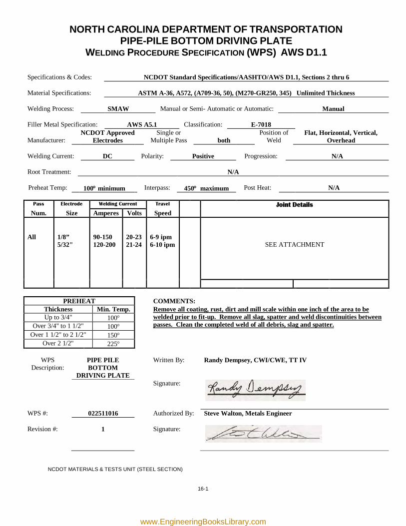
NORTH CAROLINA DEPARTMENT OF TRANSPORTATION PIPE-PILE BOTTOM DRIVING PLATE
WELDING PROCEDURE SPECIFICATION (WPS) AWS D1.1
Specifications & Codes:
NCDOT Standard Specifications/AASHTO/AWS D1.1, Sections 2 thru 6
Material Specifications:
ASTM A-36, A572, (A709-36, 50), (M270-GR250, 345) Unlimited Thickness
Welding Process:
SMAW
Manual or Semi- Automatic or Automatic:
Manual
Filler Metal Specification:
AWS A5.1
Classification:
E-7018
Manufacturer:
NCDOT Approved Electrodes
Single or Multiple Pass
both
Position of Weld
Flat, Horizontal, Vertical, Overhead
Welding Current:
DC
Polarity:
Positive
Progression:
N/A
Root Treatment:
N/A
Preheat Temp:
100° minimum
Interpass:
450° maximum
Post Heat:
N/A
Pass Electrode Welding Current Travel Joint Details
Num. Size Amperes Volts Speed All
1/8” 5/32"
90-150 120-200
20-23 21-24
6-9 ipm 6-10 ipm
SEE ATTACHMENT
PREHEAT COMMENTS: Thickness Min. Temp. Remove all coating, rust, dirt and mill scale within one inch of the area to be
welded prior to fit-up. Remove all slag, spatter and weld discontinuities between passes. Clean the completed weld of all debris, slag and spatter.
Up to 3/4" 100° Over 3/4" to 1 1/2" 100°
Over 1 1/2" to 2 1/2" 150° Over 2 1/2" 225°
WPS
Description: PIPE PILE BOTTOM
DRIVING PLATE
Written By: Randy Dempsey, CWI/CWE, TT IV
Signature:
WPS #: 022511016 Authorized By: Steve Walton, Metals Engineer Revision #:
1
Signature:
NCDOT MATERIALS & TESTS UNIT (STEEL SECTION)
www.EngineeringBooksLibrary.com
BEVEL \VELD, ARRO\vSIDE with BEVELANGLE
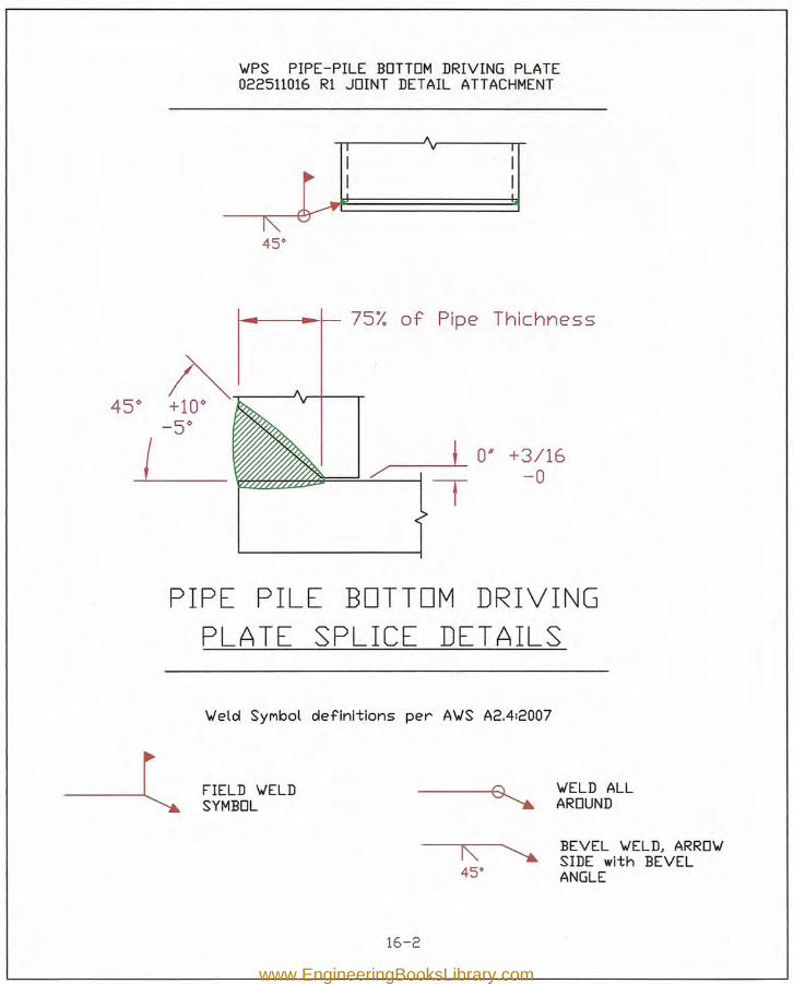
\vPS PIPE-PILE BOTTOM DRIVING PLATE022511016 R1 JOINT DETAIL ATTACHMENT
AI V I
I I~ I I-I~ oJ
45"
f-II-----+__ 75% of Pipe Thichness
/ ____-L 0" +3/16/' ! -0
PIPE PILE BOTTOM DRIVINGPLATE SPLICE DETAILS
\Veld SYMbol definitions per A'WS A2.412007
FIELD \VELDSYMBOL
\VELD ALLAROUND
16-2
www.EngineeringBooksLibrary.com
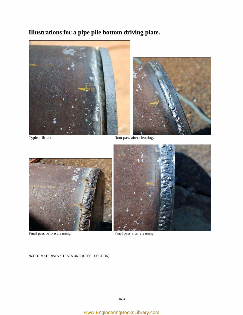
16-3
Illustrations for a pipe pile bottom driving plate.
Typical fit-up. Root pass after cleaning.
Final pass before cleaning. Final pass after cleaning NCDOT MATERIALS & TESTS UNIT (STEEL SECTION)
www.EngineeringBooksLibrary.com

[this page was intentionally left blank]
www.EngineeringBooksLibrary.com
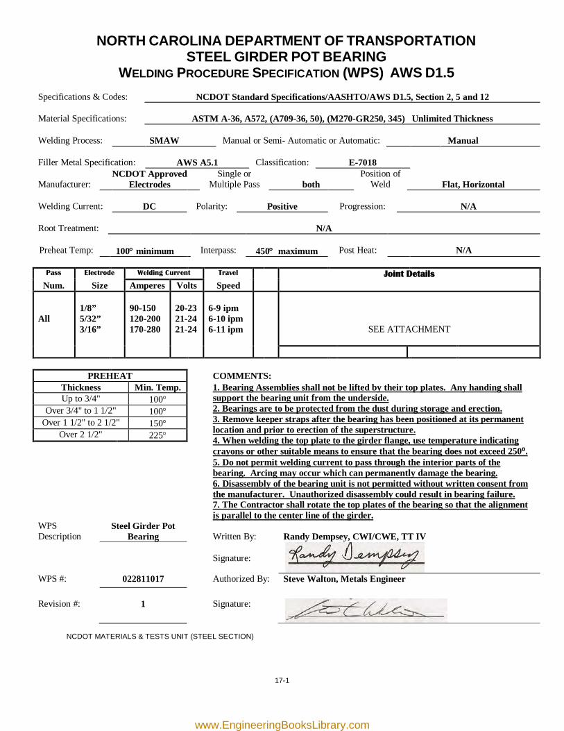
17-1
NORTH CAROLINA DEPARTMENT OF TRANSPORTATION STEEL GIRDER POT BEARING
WELDING PROCEDURE SPECIFICATION (WPS) AWS D1.5 Specifications & Codes:
NCDOT Standard Specifications/AASHTO/AWS D1.5, Section 2, 5 and 12
Material Specifications:
ASTM A-36, A572, (A709-36, 50), (M270-GR250, 345) Unlimited Thickness
Welding Process:
SMAW
Manual or Semi- Automatic or Automatic:
Manual
Filler Metal Specification:
AWS A5.1
Classification:
E-7018
Manufacturer:
NCDOT Approved Electrodes
Single or Multiple Pass
both
Position of Weld
Flat, Horizontal
Welding Current:
DC
Polarity:
Positive
Progression:
N/A
Root Treatment:
N/A
Preheat Temp:
100° minimum
Interpass:
450° maximum
Post Heat:
N/A
Pass Electrode Welding Current Travel Joint Details
Num. Size Amperes Volts Speed All
1/8” 5/32” 3/16”
90-150 120-200 170-280
20-23 21-24 21-24
6-9 ipm 6-10 ipm 6-11 ipm
SEE ATTACHMENT
PREHEAT COMMENTS: Thickness Min. Temp. 1. Bearing Assemblies shall not be lifted by their top plates. Any handing shall
support the bearing unit from the underside. 2. Bearings are to be protected from the dust during storage and erection. 3. Remove keeper straps after the bearing has been positioned at its permanent location and prior to erection of the superstructure. 4. When welding the top plate to the girder flange, use temperature indicating crayons or other suitable means to ensure that the bearing does not exceed 250⁰. 5. Do not permit welding current to pass through the interior parts of the bearing. Arcing may occur which can permanently damage the bearing. 6. Disassembly of the bearing unit is not permitted without written consent from the manufacturer. Unauthorized disassembly could result in bearing failure. 7. The Contractor shall rotate the top plates of the bearing so that the alignment is parallel to the center line of the girder.
Up to 3/4" 100° Over 3/4" to 1 1/2" 100°
Over 1 1/2" to 2 1/2" 150° Over 2 1/2" 225°
WPS Description
Steel Girder Pot Bearing
Written By:
Randy Dempsey, CWI/CWE, TT IV
Signature:
WPS #: 022811017 Authorized By: Steve Walton, Metals Engineer Revision #:
1
Signature:
NCDOT MATERIALS & TESTS UNIT (STEEL SECTION)
www.EngineeringBooksLibrary.com
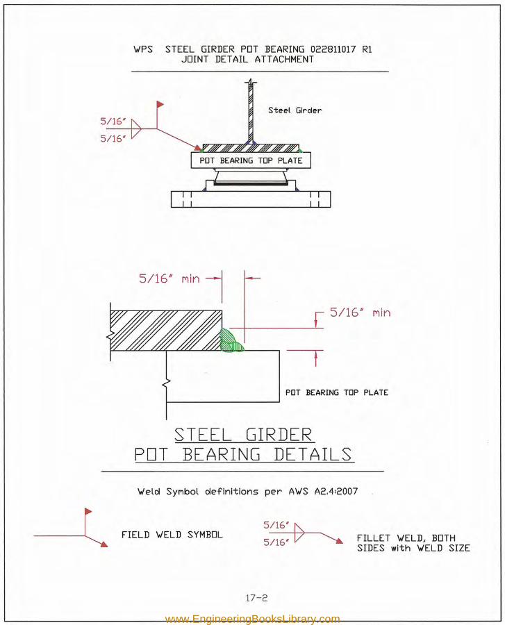
FIELD VELD SYMBOL5~
5/16' V ~ FILLET VELD, BOTHSIDES with VELD SIZE
VPS STEEL GIRDER POT BEARING 022811017 RlJOINT DETAIL ATTACHMENT
Steel Girder5/16#
5/16#
5/16' nln15/16/1 nln
rPDT BEARING TOP PLATE
STEEL GIRDERPOT BEARING DETAILSVeld SYMbol definitions per AVS A2.4:2007
17-2
www.EngineeringBooksLibrary.com
17-3
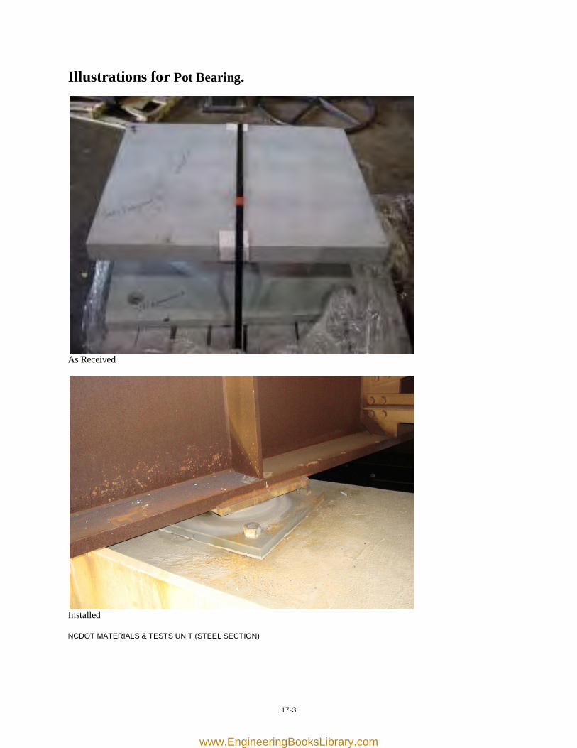
Illustrations for Pot Bearing.
As Received
Installed NCDOT MATERIALS & TESTS UNIT (STEEL SECTION)
www.EngineeringBooksLibrary.com

[this page was intentionally left blank]
www.EngineeringBooksLibrary.com
18-1
NORTH CAROLINA DEPARTMENT OF TRANSPORTATION SOLDIER-PILE
WELDING PROCEDURE SPECIFICATION (WPS) AWS D1.5
Specifications & Codes:
NCDOT Standard Specifications/AASHTO/AWS D1.5, Section 2, 5 and 12
Material Specifications:
ASTM A-36, A572, (A709-36, 50), (M270-GR250, 345) Unlimited Thickness
Welding Process:
SMAW
Manual or Semi- Automatic or Automatic:
Manual
Filler Metal Specification:
AWS A5.1
Classification:
E-7018
Manufacturer:
NCDOT Approved Electrodes
Single or Multiple Pass
both
Position of Weld
Flat, Horizontal, Vertical, Overhead
Welding Current:
DC
Polarity:
Positive
Progression:
Vertical – up
Root Treatment:
N/A
Preheat Temp:
100° minimum
Interpass:
450° maximum
Post Heat:
N/A
Pass Electrode Welding Current Travel Joint Details
Num. Size Amperes Volts Speed All
1/8” 5/32"
90-150 120-200
20-23 21-24
6-9 ipm 6-10 ipm
SEE ATTACHMENT
PREHEAT COMMENTS: Thickness Min. Temp. Remove all coating, rust, dirt and mill scale within one inch of the area to be
welded prior to fit-up. Remove all slag, spatter and weld discontinuities between passes. Clean the completed weld of all debris, slag and spatter.
Up to 3/4" 100° Over 3/4" to 1 1/2" 100°
Over 1 1/2" to 2 1/2" 150° Over 2 1/2" 225°
WPS Description SOLDIER-PILE Written By: Randy Dempsey, CWI/CWE, TT IV
Signature:
WPS #: 030811018 Authorized By: Steve Walton, Metals Engineer Revision #:
1
Signature:
NCDOT MATERIALS & TESTS UNIT (STEEL SECTION)
www.EngineeringBooksLibrary.com
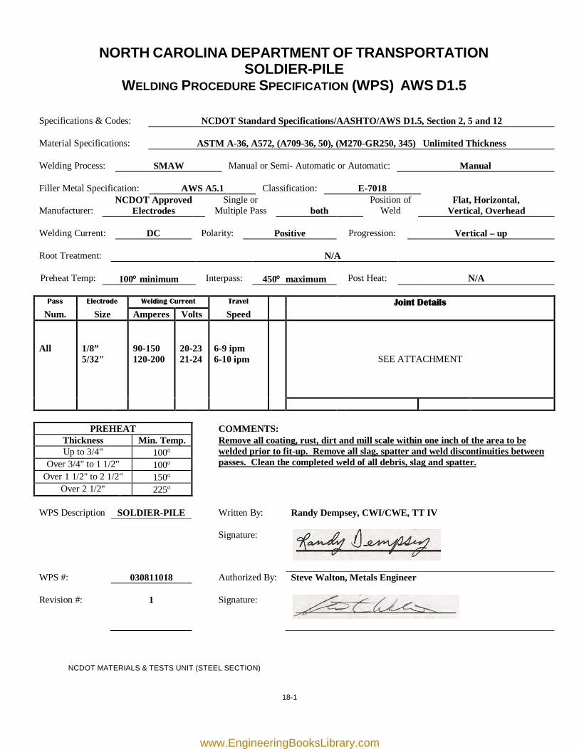
'YIPS SOLDIER-PILE 030811018 R1 JOINT DETAIL ATTACHMENT 1,.(cut holes in flOonge o.nd r-emove web MOoteriOoD
SOLDIER-PILE wEB DETAILS
'YIeld SYMbol definitions per A'YIS A2.412007
--lFIELD 'YIELD SYMBOL
114 V
III·II, -0IIIIII. 1-
.e-: Vv---ll
18-2
FILLET 'YIELD, ARRO'YISIDE with 'YIELD SIZE
www.EngineeringBooksLibrary.com
~ FIELD 'JELD SYMBOL114 V
FILLET 'WELD) ARRO'WSIDE with 'WELD SIZE
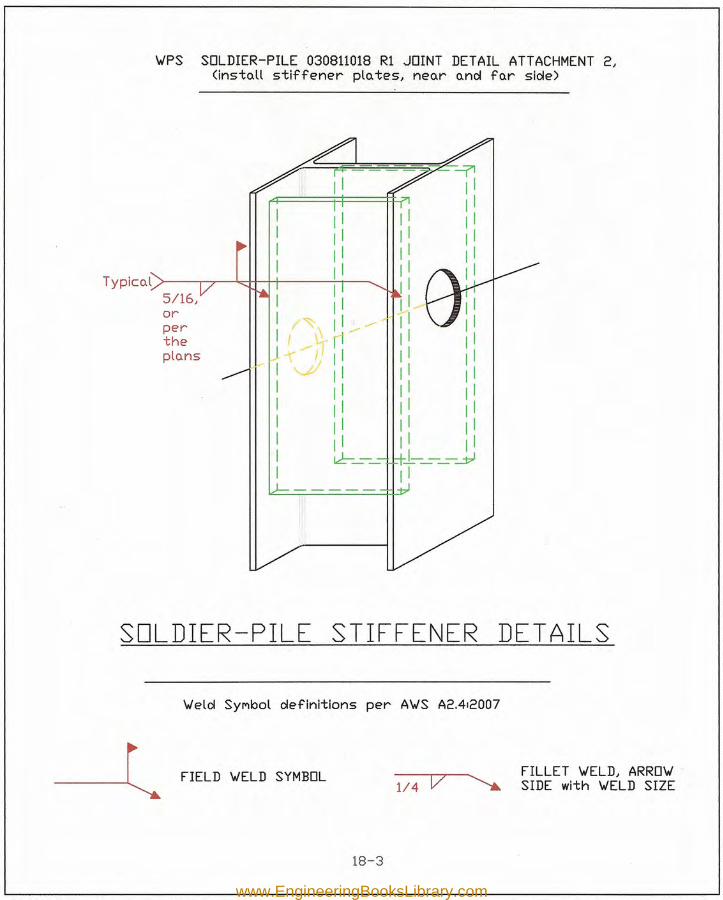
'WPS SOLDIER-PILE 030811018 Rl JOINT DETAIL ATTACHMENT 2)<install stiffener plates) near and far side)
Typical >-----,~~-H-+-+-----'-t--___.
SOLDIER-PILE STIFFENER DET AILS
'Weld SYMbol definitions per A'WS A2.412007
18-3
www.EngineeringBooksLibrary.com
FIELD VlELD SYMBOL114 V
FILLET VlELD, ARROVISIDE with VlELD SIZE
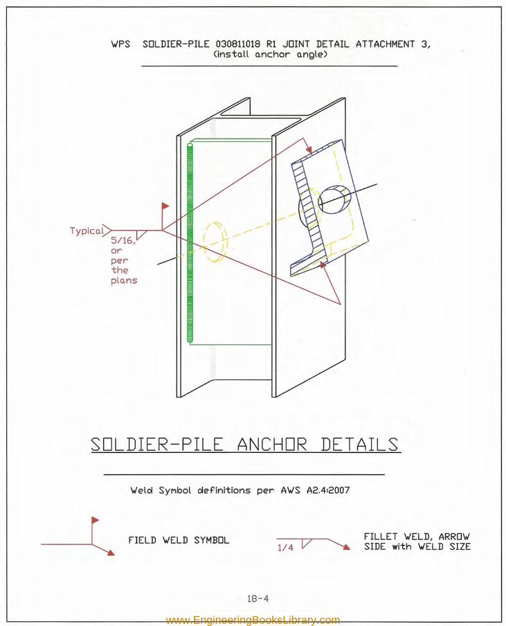
VIPS SOLDIER-PILE 030811018 Rl JOINT DETAIL ATTACHMENT 3,<insto.ll o.nchor o.ngle)
5/16,orpertheplo.ns
/~\ »>\ ----.Typlco.l >-----r-r-~
SOLDIER-PILE ANCHOR DETAILSVlelcl SYMbol clefinltions per AVIS A2.412007
18-4
www.EngineeringBooksLibrary.com
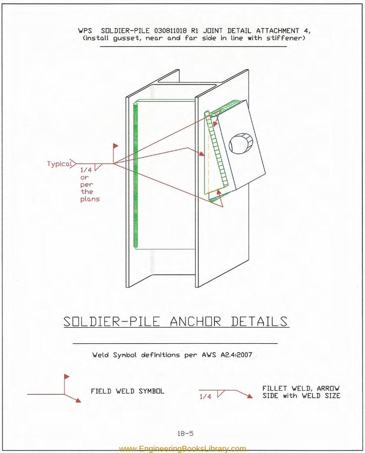
FIELD 'WELD SYMBOL114 V
FILLET 'WELD, ARRO'WSIDE with 'WELD SIZE
'WPS SOLDIER-PILE 030811018 R1 JOINT DETAIL ATTACHMENT 4,<insto.ll gusset, neo.r o.nd fo.r side in line with stiffener)
Typico.l >---r-r-----'<:::-114orpertheplo.ns
SOLDIER-PILE ANCHOR DETAILS'Weld SYMbol definitions per A'WS A2.412007 .
18-5
www.EngineeringBooksLibrary.com
18-6
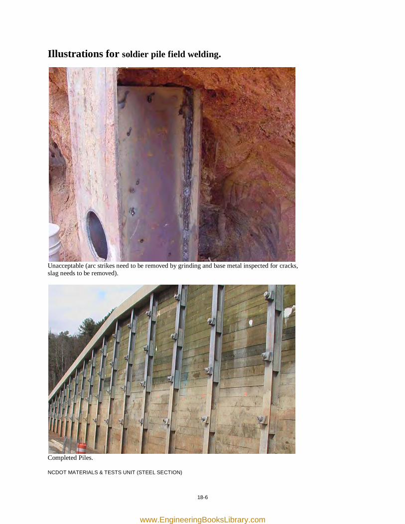
Illustrations for soldier pile field welding.
Unacceptable (arc strikes need to be removed by grinding and base metal inspected for cracks, slag needs to be removed).
Completed Piles. NCDOT MATERIALS & TESTS UNIT (STEEL SECTION)
www.EngineeringBooksLibrary.com
21-1
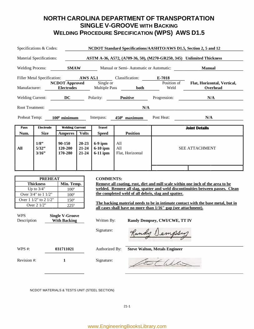
NORTH CAROLINA DEPARTMENT OF TRANSPORTATION SINGLE V-GROOVE WITH BACKING
WELDING PROCEDURE SPECIFICATION (WPS) AWS D1.5
Specifications & Codes:
NCDOT Standard Specifications/AASHTO/AWS D1.5, Section 2, 5 and 12
Material Specifications:
ASTM A-36, A572, (A709-36, 50), (M270-GR250, 345) Unlimited Thickness
Welding Process:
SMAW
Manual or Semi- Automatic or Automatic:
Manual
Filler Metal Specification:
AWS A5.1
Classification:
E-7018
Manufacturer:
NCDOT Approved Electrodes
Single or Multiple Pass
both
Position of Weld
Flat, Horizontal, Vertical, Overhead
Welding Current:
DC
Polarity:
Positive
Progression:
N/A
Root Treatment:
N/A
Preheat Temp:
100° minimum
Interpass:
450° maximum
Post Heat:
N/A
Pass Electrode Welding Current Travel Joint Details
Num. Size Amperes Volts Speed Position All
1/8” 5/32” 3/16”
90-150 120-200 170-280
20-23 21-24 21-24
6-9 ipm 6-10 ipm 6-11 ipm
All All Flat, Horizontal
SEE ATTACHMENT
PREHEAT COMMENTS: Thickness Min. Temp.
Remove all coating, rust, dirt and mill scale within one inch of the area to be welded. Remove all slag, spatter and weld discontinuities between passes. Clean the completed weld of all debris, slag and spatter.
The backing material needs to be in intimate contact with the base metal, but in all cases shall have no more than 1/16" gap (see attachment).
Up to 3/4" 100° Over 3/4" to 1 1/2" 100°
Over 1 1/2" to 2 1/2" 150° Over 2 1/2" 225°
WPS Description
Single V-Groove With Backing
Written By:
Randy Dempsey, CWI/CWE, TT IV
Signature:
WPS #: 031711021 Authorized By: Steve Walton, Metals Engineer Revision #:
1
Signature:
NCDOT MATERIALS & TESTS UNIT (STEEL SECTION)
www.EngineeringBooksLibrary.com
UnliMited
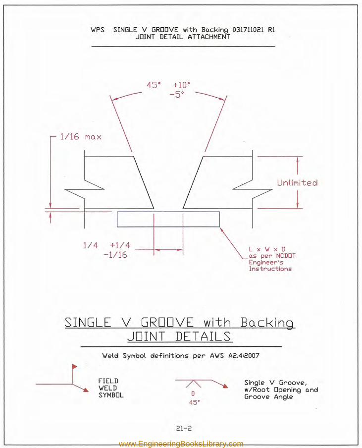
VIPS SINGLE V GROOVE with Bo.cklnq 031711021 RlJOINT DETAIL ATTACHMENT
1/16 MUX
1/4 +1/4 ---1-----<-1-1/16
Lx'vlxDns per NCDOTEngineer'sInstructions
SINGLE V GROOVE with BQckingJOINT DET AILS
Viele! Synbot e!efinitions per AVIS A2.4:2007
FIELDVlELDSYMBOL
Single V Groove I
w/Root Opening andGroove Angle
21-2
www.EngineeringBooksLibrary.com
21-3
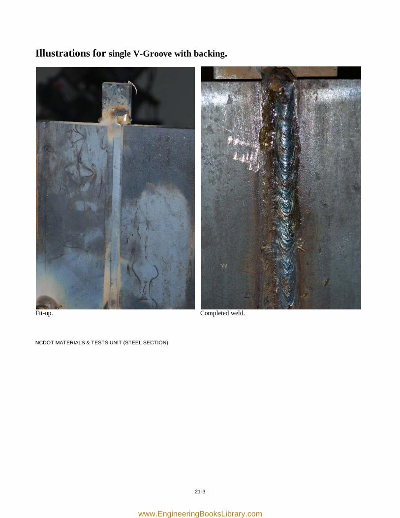
Illustrations for single V-Groove with backing.
Fit-up. Completed weld. NCDOT MATERIALS & TESTS UNIT (STEEL SECTION)
www.EngineeringBooksLibrary.com

[this page was intentionally left blank]
www.EngineeringBooksLibrary.com
22-1
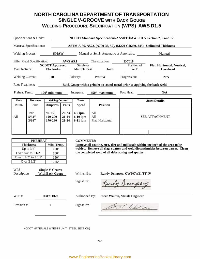
NORTH CAROLINA DEPARTMENT OF TRANSPORTATION SINGLE V-GROOVE WITH BACK GOUGE
WELDING PROCEDURE SPECIFICATION (WPS) AWS D1.5
Specifications & Codes:
NCDOT Standard Specifications/AASHTO/AWS D1.5, Section 2, 5 and 12
Material Specifications:
ASTM A-36, A572, (A709-36, 50), (M270-GR250, 345) Unlimited Thickness
Welding Process:
SMAW
Manual or Semi- Automatic or Automatic:
Manual
Filler Metal Specification:
AWS A5.1
Classification:
E-7018
Manufacturer:
NCDOT Approved Electrodes
Single or Multiple Pass
both
Position of Weld
Flat, Horizontal, Vertical, Overhead
Welding Current:
DC
Polarity:
Positive
Progression:
N/A
Root Treatment:
Back Gouge with a grinder to sound metal prior to applying the back weld.
Preheat Temp:
100° minimum
Interpass:
450° maximum
Post Heat:
N/A
Pass Electrode Welding Current Travel Joint Details
Num. Size Amperes Volts Speed Position All
1/8” 5/32” 3/16”
90-150 120-200 170-280
20-23 21-24 21-24
6-9 ipm 6-10 ipm 6-11 ipm
All All Flat, Horizontal
SEE ATTACHMENT
PREHEAT COMMENTS: Thickness Min. Temp.
Remove all coating, rust, dirt and mill scale within one inch of the area to be welded. Remove all slag, spatter and weld discontinuities between passes. Clean the completed weld of all debris, slag and spatter.
Up to 3/4" 100° Over 3/4" to 1 1/2" 100°
Over 1 1/2" to 2 1/2" 150° Over 2 1/2" 225°
WPS Description
Single V-Groove With Back Gouge
Written By:
Randy Dempsey, CWI/CWE, TT IV
Signature:
WPS #: 031711022 Authorized By: Steve Walton, Metals Engineer Revision #:
1
Signature:
NCDOT MATERIALS & TESTS UNIT (STEEL SECTION)
www.EngineeringBooksLibrary.com
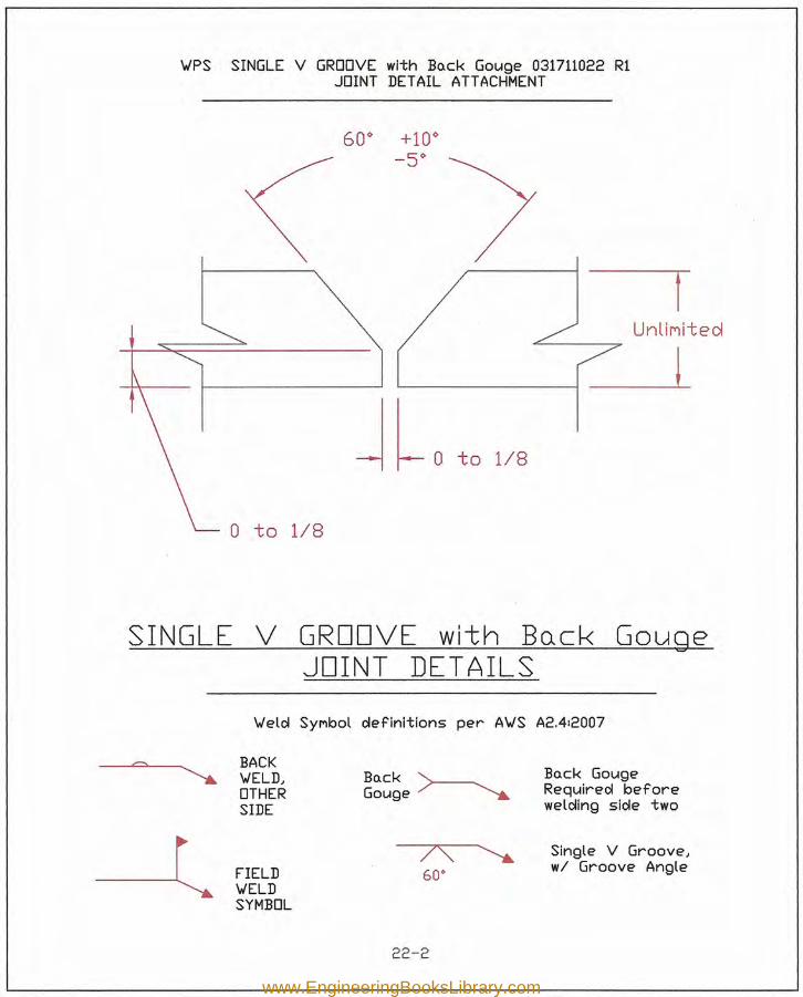
WPS SINGLE V GROOVE with Ba.ck Gouge 031711022 R1JOINT DETAIL ATTACHMENT
rUnllnt t ed
'-------1 _LJ lo to 1/8
o to 1/8
SINGLE V GROOVE with Bo.cl-< GougeJOINT DETAILS
Weld SYMbol definitions per AWS A2.412007
BACKWELD,OTHERSIDE
Ba.ck GougeRequired beforewelding side two
Ba.ck '>---.Gouge /' ~
7'\60"
Single V Groove,wi Groove AngleFIELD
WELDSYMBOL
22-2
www.EngineeringBooksLibrary.com
22-3
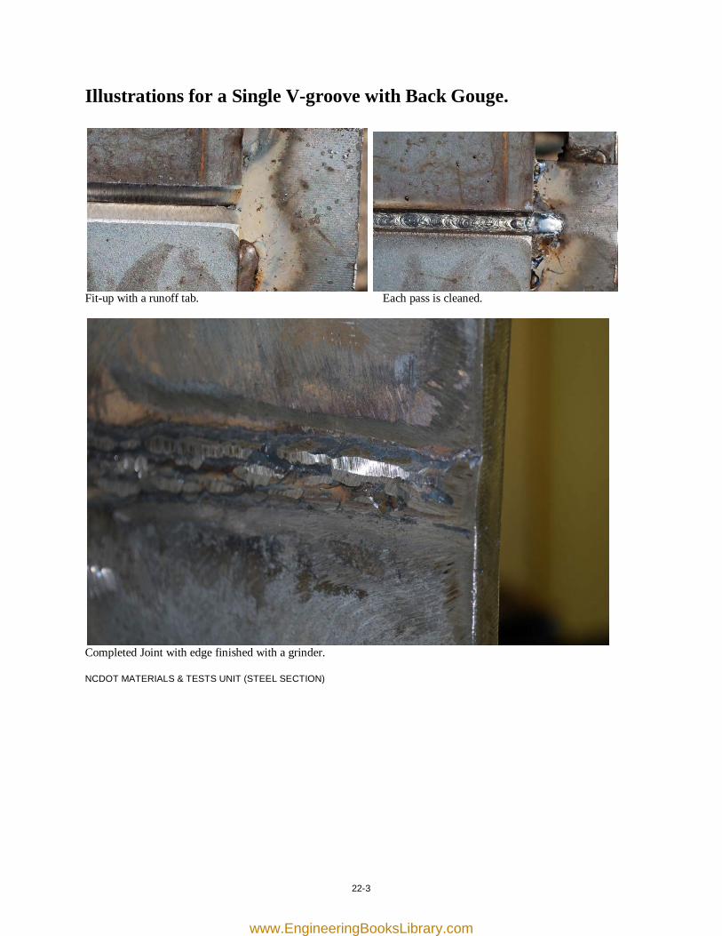
Illustrations for a Single V-groove with Back Gouge.
Fit-up with a runoff tab. Each pass is cleaned.
Completed Joint with edge finished with a grinder. NCDOT MATERIALS & TESTS UNIT (STEEL SECTION)
www.EngineeringBooksLibrary.com

[this page was intentionally left blank]
www.EngineeringBooksLibrary.com
23-1
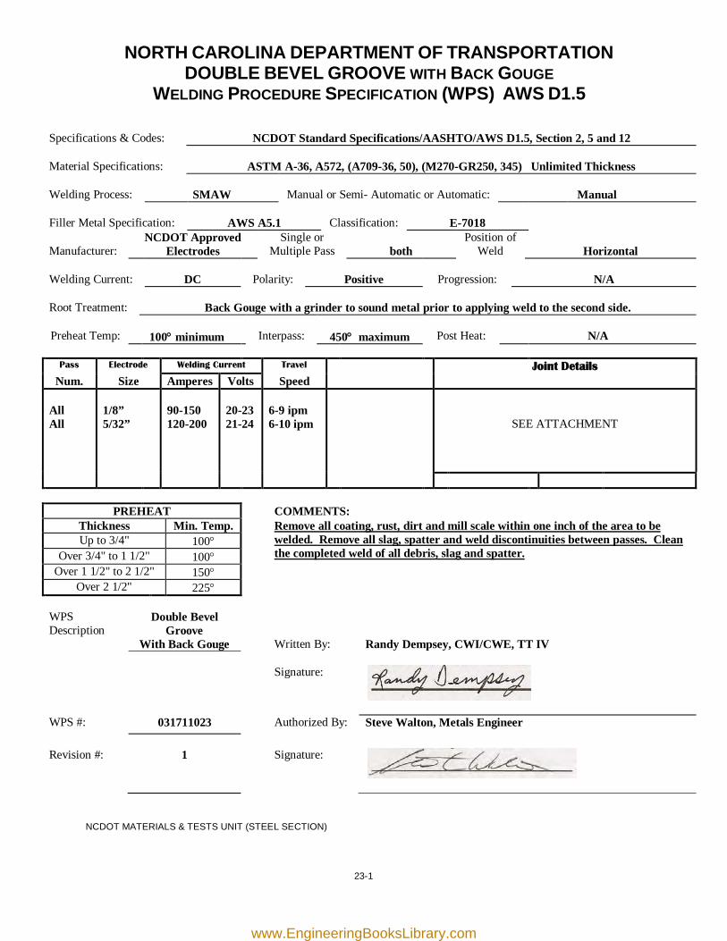
NORTH CAROLINA DEPARTMENT OF TRANSPORTATION DOUBLE BEVEL GROOVE WITH BACK GOUGE
WELDING PROCEDURE SPECIFICATION (WPS) AWS D1.5
Specifications & Codes:
NCDOT Standard Specifications/AASHTO/AWS D1.5, Section 2, 5 and 12
Material Specifications:
ASTM A-36, A572, (A709-36, 50), (M270-GR250, 345) Unlimited Thickness
Welding Process:
SMAW
Manual or Semi- Automatic or Automatic:
Manual
Filler Metal Specification:
AWS A5.1
Classification:
E-7018
Manufacturer:
NCDOT Approved Electrodes
Single or Multiple Pass
both
Position of Weld
Horizontal
Welding Current:
DC
Polarity:
Positive
Progression:
N/A
Root Treatment:
Back Gouge with a grinder to sound metal prior to applying weld to the second side.
Preheat Temp:
100° minimum
Interpass:
450° maximum
Post Heat:
N/A
Pass Electrode Welding Current Travel Joint Details
Num. Size Amperes Volts Speed All All
1/8” 5/32”
90-150 120-200
20-23 21-24
6-9 ipm 6-10 ipm
SEE ATTACHMENT
PREHEAT COMMENTS: Thickness Min. Temp. Remove all coating, rust, dirt and mill scale within one inch of the area to be
welded. Remove all slag, spatter and weld discontinuities between passes. Clean the completed weld of all debris, slag and spatter.
Up to 3/4" 100° Over 3/4" to 1 1/2" 100°
Over 1 1/2" to 2 1/2" 150° Over 2 1/2" 225°
WPS Description
Double Bevel Groove
With Back Gouge
Written By:
Randy Dempsey, CWI/CWE, TT IV
Signature:
WPS #: 031711023 Authorized By: Steve Walton, Metals Engineer Revision #:
1
Signature:
NCDOT MATERIALS & TESTS UNIT (STEEL SECTION)
www.EngineeringBooksLibrary.com
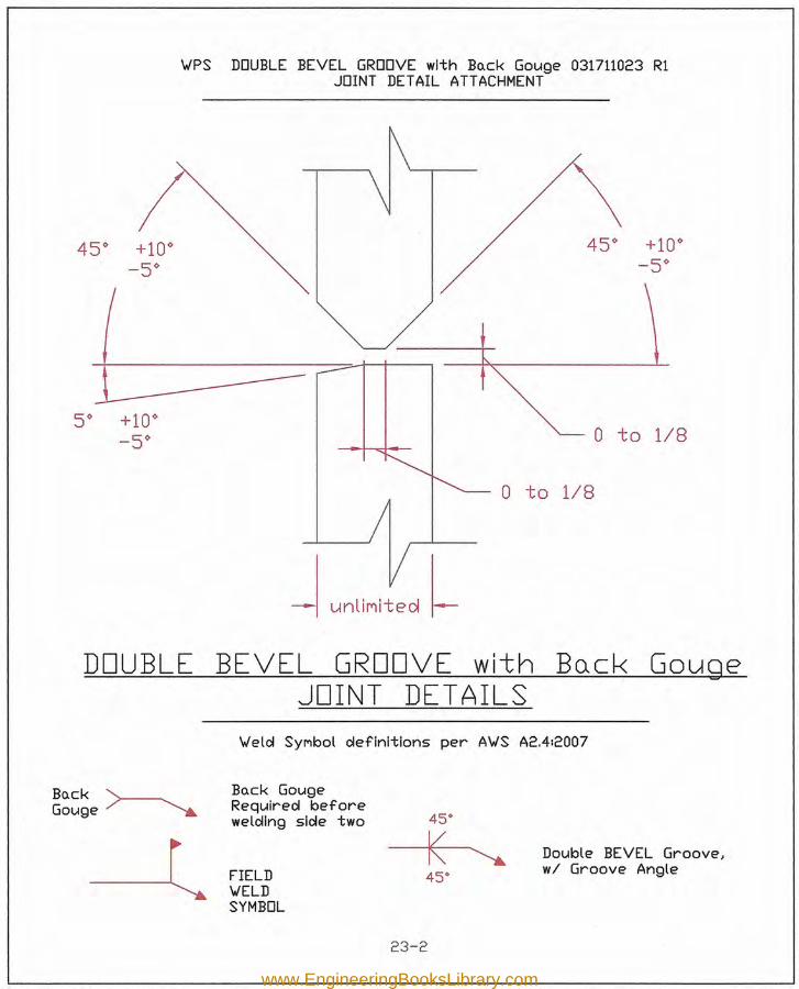
v=s DOUBLE BEVEL GROOVE with BOock Gouge 031711023 R1JOINT DETAIL ATTACHMENT
o to 1/8
o to 1/8
~ unliMited '.
DOUBLE BEVEL GROOVE with BQCK GougeJOINT DETAILS
'vIelcl SYMbol clefinitions per A'vIS A2.4:2007
BOock >-----.Gouqe :" ~
BOock GougeRequir-ed beforewelcllng slcle two-l FIELD'vIELDSYMBOL
Double BEVEL Groove I
wi Groove Angle
23-2
www.EngineeringBooksLibrary.com
23-3
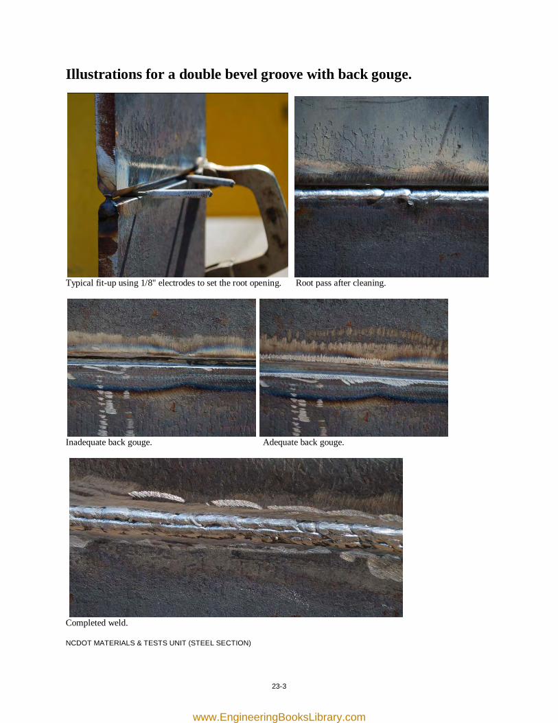
Illustrations for a double bevel groove with back gouge.
Typical fit-up using 1/8" electrodes to set the root opening. Root pass after cleaning.
Inadequate back gouge. Adequate back gouge.
Completed weld. NCDOT MATERIALS & TESTS UNIT (STEEL SECTION)
www.EngineeringBooksLibrary.com

[this page was intentionally left blank]
www.EngineeringBooksLibrary.com
25-1
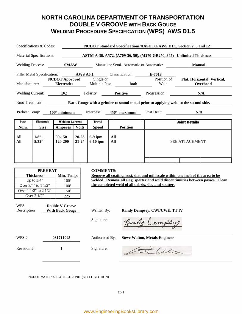
NORTH CAROLINA DEPARTMENT OF TRANSPORTATION DOUBLE V GROOVE WITH BACK GOUGE
WELDING PROCEDURE SPECIFICATION (WPS) AWS D1.5
Specifications & Codes:
NCDOT Standard Specifications/AASHTO/AWS D1.5, Section 2, 5 and 12
Material Specifications:
ASTM A-36, A572, (A709-36, 50), (M270-GR250, 345) Unlimited Thickness
Welding Process:
SMAW
Manual or Semi- Automatic or Automatic:
Manual
Filler Metal Specification:
AWS A5.1
Classification:
E-7018
Manufacturer:
NCDOT Approved Electrodes
Single or Multiple Pass
both
Position of Weld
Flat, Horizontal, Vertical, Overhead
Welding Current:
DC
Polarity:
Positive
Progression:
N/A
Root Treatment:
Back Gouge with a grinder to sound metal prior to applying weld to the second side.
Preheat Temp:
100° minimum
Interpass:
450° maximum
Post Heat:
N/A
Pass Electrode Welding Current Travel Joint Details
Num. Size Amperes Volts Speed Position All All
1/8” 5/32”
90-150 120-200
20-23 21-24
6-9 ipm 6-10 ipm
All All
SEE ATTACHMENT
PREHEAT COMMENTS: Thickness Min. Temp.
Remove all coating, rust, dirt and mill scale within one inch of the area to be welded. Remove all slag, spatter and weld discontinuities between passes. Clean the completed weld of all debris, slag and spatter.
Up to 3/4" 100° Over 3/4" to 1 1/2" 100°
Over 1 1/2" to 2 1/2" 150° Over 2 1/2" 225°
WPS Description
Double V Groove With Back Gouge
Written By:
Randy Dempsey, CWI/CWE, TT IV
Signature:
WPS #: 031711025 Authorized By: Steve Walton, Metals Engineer Revision #:
1
Signature:
NCDOT MATERIALS & TESTS UNIT (STEEL SECTION)
www.EngineeringBooksLibrary.com
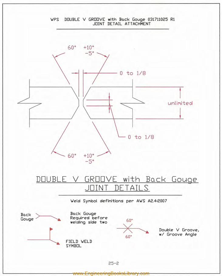
VPS DOUBLE V GROOVE with Bo.ck Gouge 031711025 R1JOINT DETAIL ATTACHMENT
1----1---- 0 to 1/8
unliMited
,---------\-----f __ Lo to 1/8
DOUBLE V GROOVE with Bo.ck GougeJOINT DETAILS
Veld SYMbol definitions per AVS A2.412007
Bo.ck '>----....Gouge ", .•......•.
BQck GougeRequired beforewelding side two-l
FIELD VELDSYMBOL
60"
>< Double V Groove J
wi Groove Angle60"
25-2
www.EngineeringBooksLibrary.com
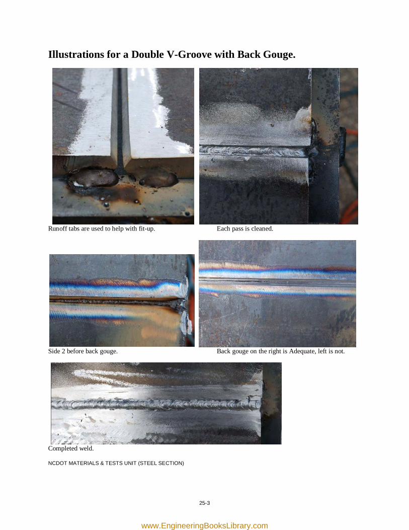
25-3
Illustrations for a Double V-Groove with Back Gouge.
Runoff tabs are used to help with fit-up. Each pass is cleaned.
Side 2 before back gouge. Back gouge on the right is Adequate, left is not.
Completed weld. NCDOT MATERIALS & TESTS UNIT (STEEL SECTION)
www.EngineeringBooksLibrary.com

[this page was intentionally left blank]
www.EngineeringBooksLibrary.com
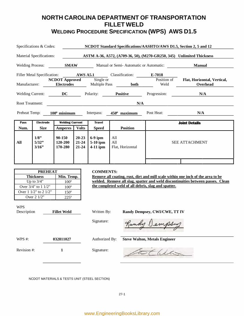
27-1
NORTH CAROLINA DEPARTMENT OF TRANSPORTATION FILLET WELD
WELDING PROCEDURE SPECIFICATION (WPS) AWS D1.5
Specifications & Codes:
NCDOT Standard Specifications/AASHTO/AWS D1.5, Section 2, 5 and 12
Material Specifications:
ASTM A-36, A572, (A709-36, 50), (M270-GR250, 345) Unlimited Thickness
Welding Process:
SMAW
Manual or Semi- Automatic or Automatic:
Manual
Filler Metal Specification:
AWS A5.1
Classification:
E-7018
Manufacturer:
NCDOT Approved Electrodes
Single or Multiple Pass
both
Position of Weld
Flat, Horizontal, Vertical, Overhead
Welding Current:
DC
Polarity:
Positive
Progression:
N/A
Root Treatment:
N/A
Preheat Temp:
100° minimum
Interpass:
450° maximum
Post Heat:
N/A
Pass Electrode Welding Current Travel Joint Details
Num. Size Amperes Volts Speed Position All
1/8” 5/32” 3/16”
90-150 120-200 170-280
20-23 21-24 21-24
6-9 ipm 5-10 ipm 4-11 ipm
All All Flat, Horizontal
SEE ATTACHMENT
PREHEAT COMMENTS: Thickness Min. Temp. Remove all coating, rust, dirt and mill scale within one inch of the area to be
welded. Remove all slag, spatter and weld discontinuities between passes. Clean the completed weld of all debris, slag and spatter.
Up to 3/4" 100° Over 3/4" to 1 1/2" 100°
Over 1 1/2" to 2 1/2" 150° Over 2 1/2" 225°
WPS Description
Fillet Weld
Written By:
Randy Dempsey, CWI/CWE, TT IV
Signature:
WPS #: 032811027 Authorized By: Steve Walton, Metals Engineer Revision #:
1
Signature:
NCDOT MATERIALS & TESTS UNIT (STEEL SECTION)
www.EngineeringBooksLibrary.com
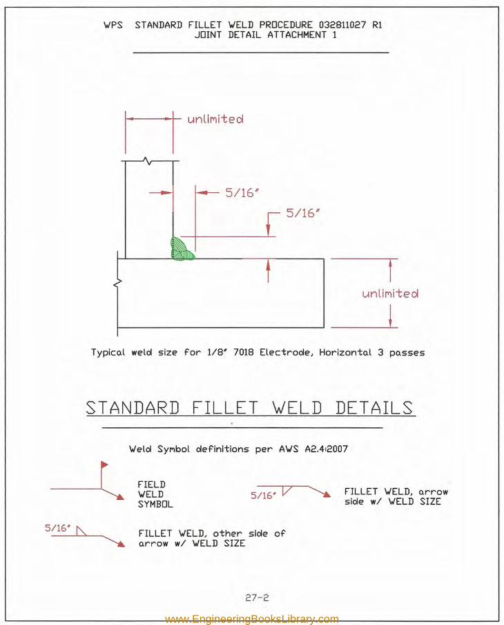
'WPS STANDARD FILLET 'WELD PROCEDURE 032811027 R1JOINT DETAIL ATTACHMENT 1
M untlnl t ed
5/16/1
5/16"
unllnrt e d
1-------- _LTypical weld size for 1/8' 7018 Electrode, Horizontal 3 passes
STANDARD FILLET ~ELD DETAILS
5/161 t\,
\Jeld SYMbol definitions per A'WS A2.412007
FIELD'WELDSYMBOL
5/161 V FILLET 'WELD, arrowside wi 'WELD SIZE
FILLET 'WELD, other side ofarrow wi 'WELD SIZE
27-2
www.EngineeringBooksLibrary.com
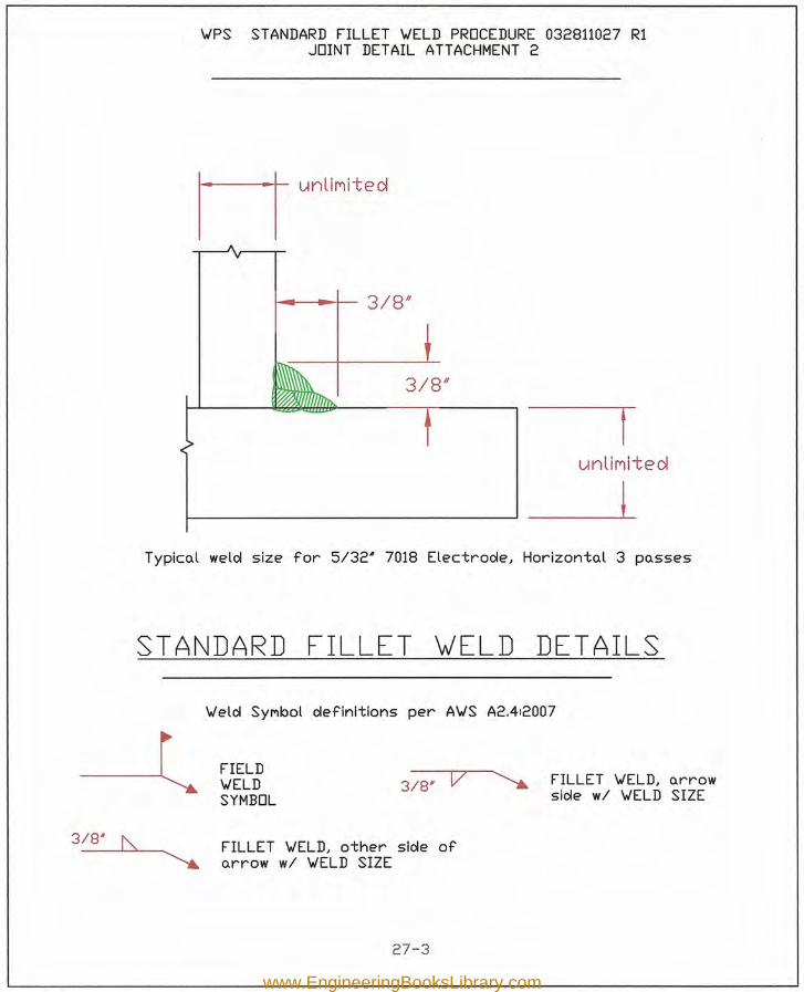
v=s STANDARD FILLET 'vIELD PROCEDURE 032811027 R1JOINT DETAIL ATTACHMENT 2
MunliMited
I--------L
~--t-+-- 3/8/1
3/8/1
runllnl+e d
Typico.l welol size for 5/32' 7018 Electroole, Horizonto.l 3 po.sses
STANDARD FILLET ~ELD DETAILS
3/8' f\,
'vIeloi SYMbol oIeflnltlons per A'vIS A2.412007
FIELD'vIELDSYMBOL
3/8' V FILLET 'vIELD, o.rrowslole wi 'vIELD SIZE
FILLET 'vIELD, other slole ofo.rrow wi 'vIELD SIZE
27-3
www.EngineeringBooksLibrary.com
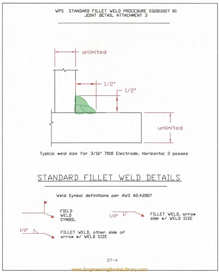
\-IPS STANDARD FILLET \-IELD PROCEDURE032811027 R1JOINT DETAIL ATTACHMENT 3
Munllnl t ed
1---------' _L
~---+- 1/2"1/2"
unllnlt.e d
Typicol weld size for 3/16' 7018 Electrode, Horizontol 3 posses
STANDARD FILLET ~ELD DETAILS
-l112' I\.
\-Ield SYMbol definitions per A\-IS A2.412007
FIELD\-IELDSYMBOL
112' V FILLET \-IELD, orrowside wi \-IELD SIZE
FILLET \-IELD, other side oforrow wi \-IELD SIZE
27-4
www.EngineeringBooksLibrary.com
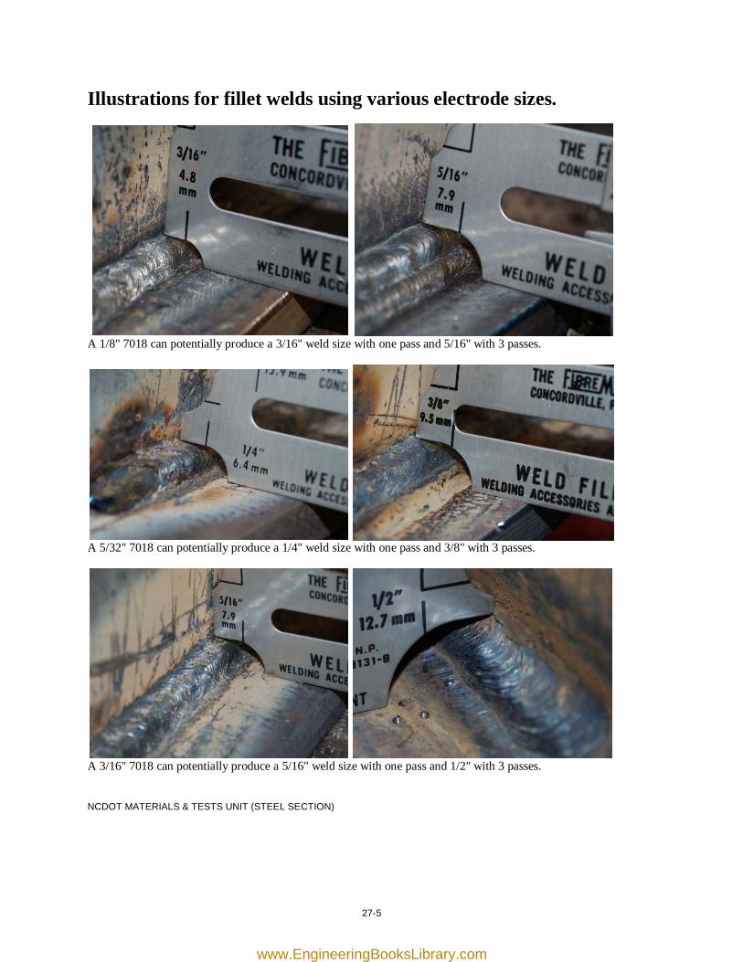
27-5
Illustrations for fillet welds using various electrode sizes.
A 1/8" 7018 can potentially produce a 3/16" weld size with one pass and 5/16" with 3 passes.
A 5/32" 7018 can potentially produce a 1/4" weld size with one pass and 3/8" with 3 passes.
A 3/16" 7018 can potentially produce a 5/16" weld size with one pass and 1/2" with 3 passes. NCDOT MATERIALS & TESTS UNIT (STEEL SECTION)
www.EngineeringBooksLibrary.com

[this page was intentionally left blank]
www.EngineeringBooksLibrary.com
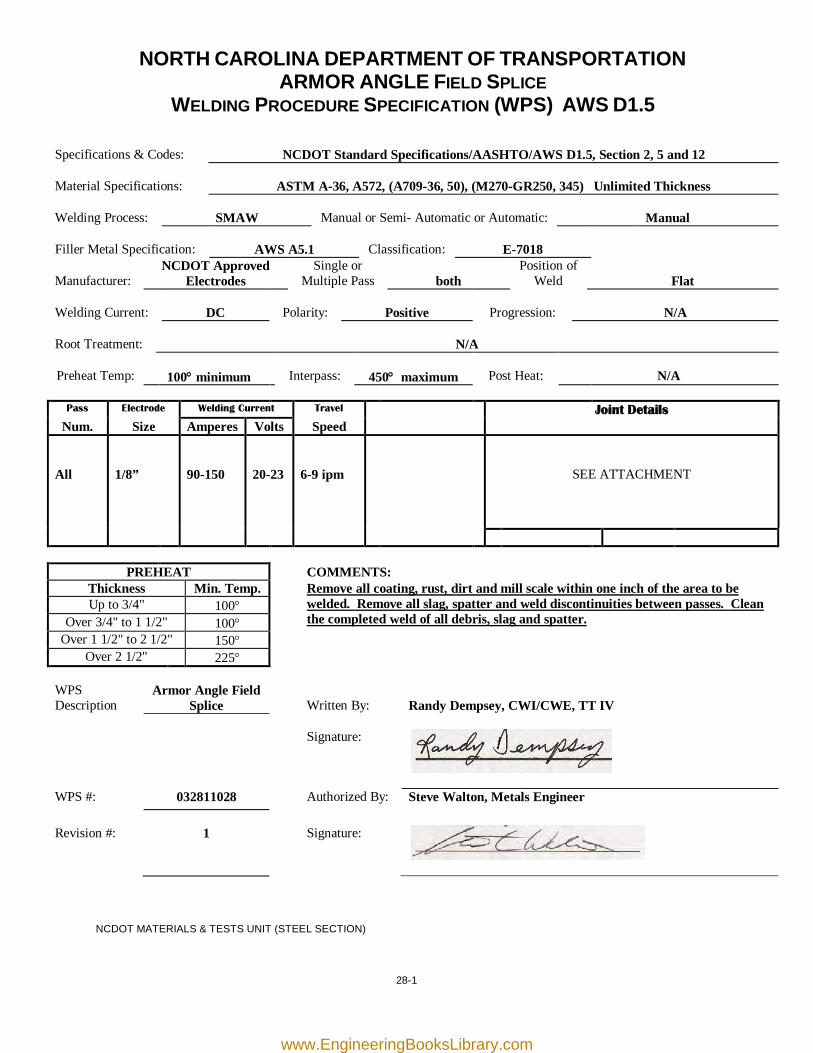
28-1
NORTH CAROLINA DEPARTMENT OF TRANSPORTATION ARMOR ANGLE FIELD SPLICE
WELDING PROCEDURE SPECIFICATION (WPS) AWS D1.5
Specifications & Codes:
NCDOT Standard Specifications/AASHTO/AWS D1.5, Section 2, 5 and 12
Material Specifications:
ASTM A-36, A572, (A709-36, 50), (M270-GR250, 345) Unlimited Thickness
Welding Process:
SMAW
Manual or Semi- Automatic or Automatic:
Manual
Filler Metal Specification:
AWS A5.1
Classification:
E-7018
Manufacturer:
NCDOT Approved Electrodes
Single or Multiple Pass
both
Position of Weld
Flat
Welding Current:
DC
Polarity:
Positive
Progression:
N/A
Root Treatment:
N/A
Preheat Temp:
100° minimum
Interpass:
450° maximum
Post Heat:
N/A
Pass Electrode Welding Current Travel Joint Details
Num. Size Amperes Volts Speed All
1/8”
90-150
20-23
6-9 ipm
SEE ATTACHMENT
PREHEAT COMMENTS: Thickness Min. Temp. Remove all coating, rust, dirt and mill scale within one inch of the area to be
welded. Remove all slag, spatter and weld discontinuities between passes. Clean the completed weld of all debris, slag and spatter.
Up to 3/4" 100° Over 3/4" to 1 1/2" 100°
Over 1 1/2" to 2 1/2" 150° Over 2 1/2" 225°
WPS Description
Armor Angle Field Splice
Written By:
Randy Dempsey, CWI/CWE, TT IV
Signature:
WPS #: 032811028 Authorized By: Steve Walton, Metals Engineer Revision #:
1
Signature:
NCDOT MATERIALS & TESTS UNIT (STEEL SECTION)
www.EngineeringBooksLibrary.com
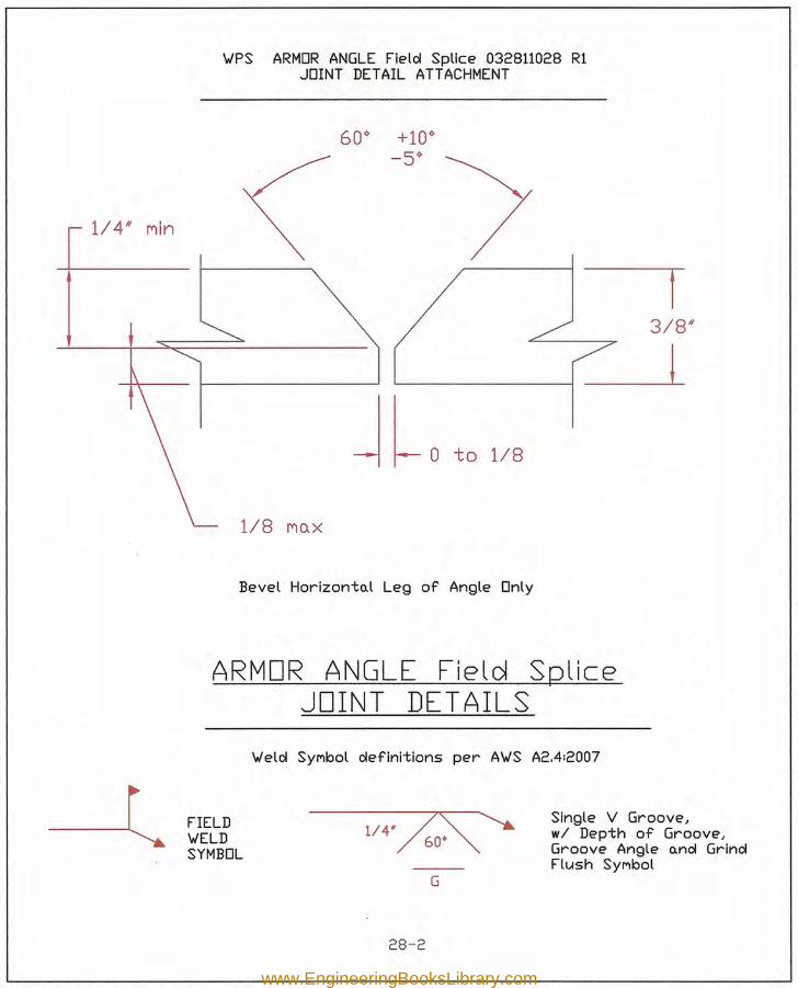
3/8/1
'WPS ARMOR ANGLE Fiele! Splice 032811028 RlJOINT DETAIL ATTACHMENT
1/4/1 nln
J l., to 1/8
1/8 MQ.X
Bevel Horizonto.l Leg of Angle Only
ARMORJOINT
ANGLE Field SpliceDETAILS
'Wele! SYMbol e!efinitions per A'WS A2.4:2007
FIELD'WELDSYMBOL
Single V Groove,wi Depth of Groove,Groove Angle o.ne! Grine!Flush SYMbol
G
28-2
www.EngineeringBooksLibrary.com
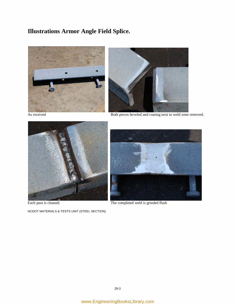
28-3
Illustrations Armor Angle Field Splice.
As received Both pieces beveled and coating next to weld zone removed.
Each pass is cleaned. The completed weld is grinded flush NCDOT MATERIALS & TESTS UNIT (STEEL SECTION)
www.EngineeringBooksLibrary.com

[this page was intentionally left blank]
www.EngineeringBooksLibrary.com
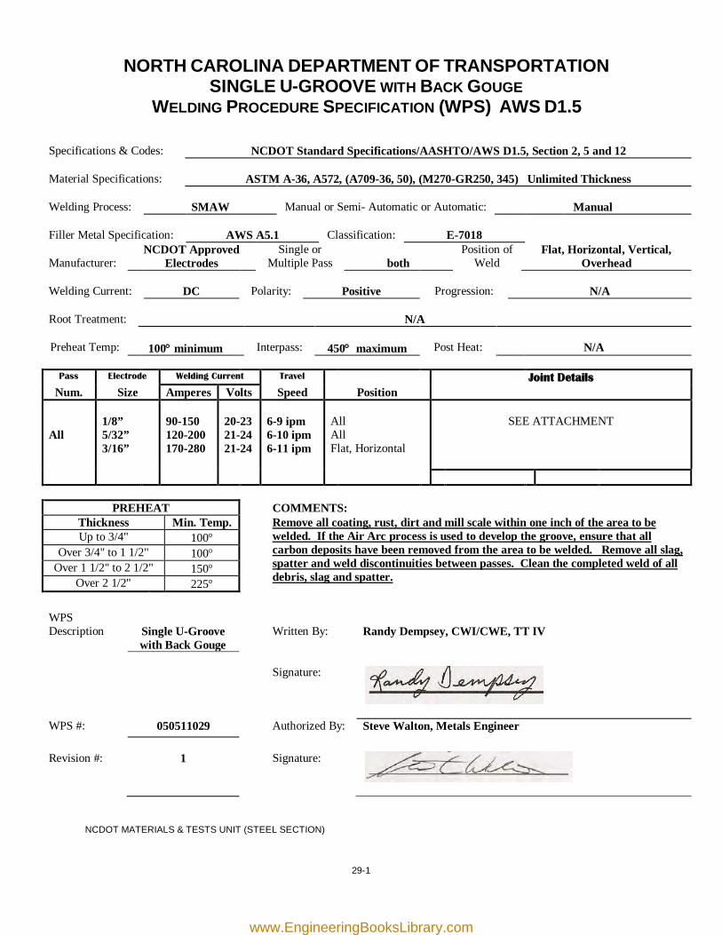
29-1
NORTH CAROLINA DEPARTMENT OF TRANSPORTATION SINGLE U-GROOVE WITH BACK GOUGE
WELDING PROCEDURE SPECIFICATION (WPS) AWS D1.5
Specifications & Codes:
NCDOT Standard Specifications/AASHTO/AWS D1.5, Section 2, 5 and 12
Material Specifications:
ASTM A-36, A572, (A709-36, 50), (M270-GR250, 345) Unlimited Thickness
Welding Process:
SMAW
Manual or Semi- Automatic or Automatic:
Manual
Filler Metal Specification:
AWS A5.1
Classification:
E-7018
Manufacturer:
NCDOT Approved Electrodes
Single or Multiple Pass
both
Position of Weld
Flat, Horizontal, Vertical, Overhead
Welding Current:
DC
Polarity:
Positive
Progression:
N/A
Root Treatment:
N/A
Preheat Temp:
100° minimum
Interpass:
450° maximum
Post Heat:
N/A
Pass Electrode Welding Current Travel Joint Details
Num. Size Amperes Volts Speed Position All
1/8” 5/32” 3/16”
90-150 120-200 170-280
20-23 21-24 21-24
6-9 ipm 6-10 ipm 6-11 ipm
All All Flat, Horizontal
SEE ATTACHMENT
PREHEAT COMMENTS: Thickness Min. Temp. Remove all coating, rust, dirt and mill scale within one inch of the area to be
welded. If the Air Arc process is used to develop the groove, ensure that all carbon deposits have been removed from the area to be welded. Remove all slag, spatter and weld discontinuities between passes. Clean the completed weld of all debris, slag and spatter.
Up to 3/4" 100° Over 3/4" to 1 1/2" 100°
Over 1 1/2" to 2 1/2" 150° Over 2 1/2" 225°
WPS Description
Single U-Groove with Back Gouge
Written By:
Randy Dempsey, CWI/CWE, TT IV
Signature:
WPS #: 050511029 Authorized By: Steve Walton, Metals Engineer Revision #:
1
Signature:
NCDOT MATERIALS & TESTS UNIT (STEEL SECTION)
www.EngineeringBooksLibrary.com
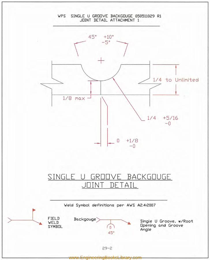
\JPS SINGLE U GROOVE BACKGOUGE 050511029 RlJOINT DETAIL ATTACHMENT 1
rUnlit")ited
I------I----'---~--j __ L1/8 t")Q.X
1/4 +5/16-0
+1/8-0
SINGLE U GROOVE BACKGDUGEJOINT DET AIL
\Jelol Synbot oIeflnltlons per A\JS A2.412007
FIELD\JELDSYMBOL
Single U Groove, w/RootOpening o.nol GrooveAngle
29-2
www.EngineeringBooksLibrary.com
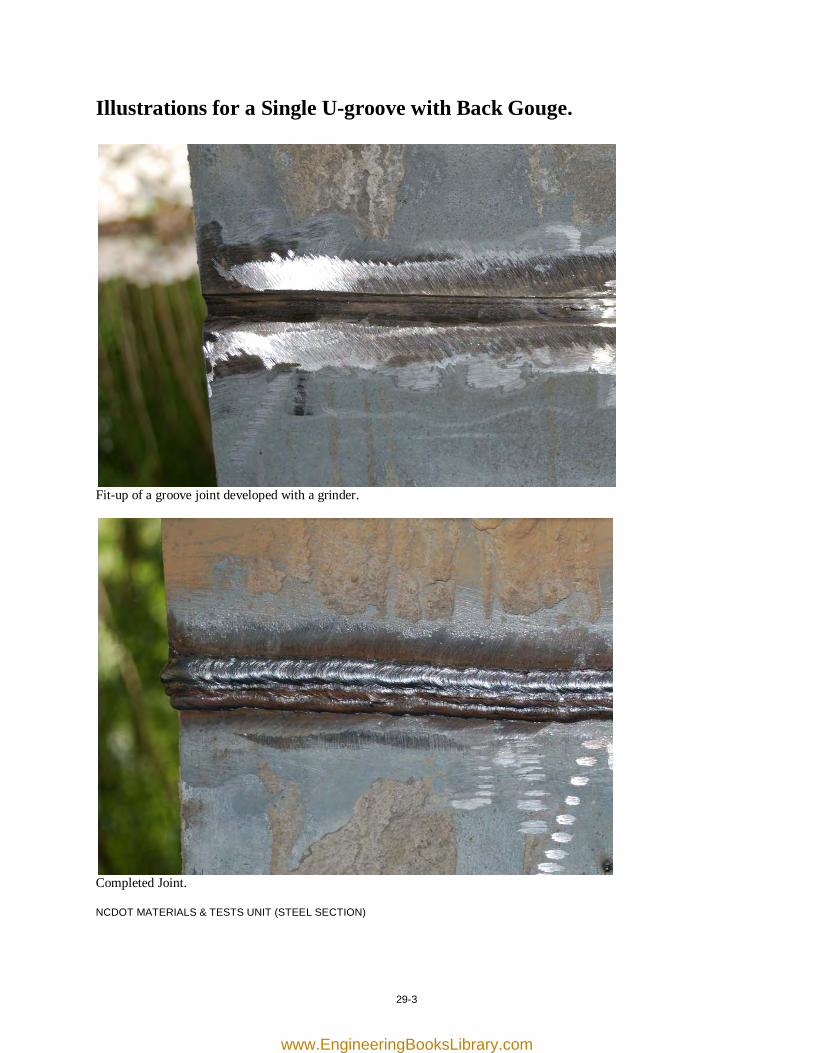
29-3
Illustrations for a Single U-groove with Back Gouge.
Fit-up of a groove joint developed with a grinder.
Completed Joint. NCDOT MATERIALS & TESTS UNIT (STEEL SECTION)
www.EngineeringBooksLibrary.com

[this page was intentionally left blank]
www.EngineeringBooksLibrary.com
Appendix A WELDING TERMS AND DEFINITIONS
A
acceptable weld A weld that meets the applicable requirements. aligned porosity A localized array of porosity oriented in a line. arc blow The deflection of an arc from its normal path due to magnetic forces. arc strike A discontinuity resulting from an arc, consisting of any localized re-melted metal, heat-affected metal, or change in the surface profile of any metal object.
B
backgouging The removal of weld metal and base metal from the weld root side of a welded joint to facilitate complete fusion and complete joint penetration upon subsequent welding from that side. backing A material placed against the back side of the joint adjacent to the joint root to support and shield molten weld metal. backing ring Backing in the form of a ring, generally used in pipe welding (also referred to as a chill ring). backing weld Backing in the form of a weld (applied prior to the single groove weld which then requires backgouging to be performed from the groove side). Not permitted unless used with an approved WPS. back weld A weld made at the back of a single groove weld. base material The material that is welded, brazed, soldered or cut (also referred to as base metal). bevel angle The angle between the bevel of a joint member and a plane perpendicular to the surface of the member. bevel face The prepared surface of a bevel edge shape.
A-1
www.EngineeringBooksLibrary.com
Appendix A WELDING TERMS AND DEFINITIONS buildup A surfacing variation in which surfacing material is deposited to achieve the required dimensions. See also buttering. buttering A surfacing variation that deposits surfacing metal [weld metal] on one or more surfaces to provide compatible material for the subsequent completion of the weld. butt joint A joint between two members aligned approximately in the same plane.
C carbon arc cutting An arc cutting process that uses a carbon electrode. carbon electrode A non-filler metal electrode used in arc welding and cutting, consisting of a carbon or graphic rod, which may be coated with copper or other materials. caulking Plastic deformation of weld and adjacent base metal surfaces by mechanical means to seal or obscure discontinuities. chain intermittent weld An intermittent weld on both sides of a joint in which the weld increments on one side are approximately opposite those on the other side. chill ring A nonstandard term when used for backing ring. cluster porosity A localized array of porosity having a random geometric distribution. cold lap A nonstandard term when used for incomplete fusion or overlap. complete joint penetration (CJP) A groove weld condition in which weld metal extends through the joint thickness. continuous weld A weld that extends continuously from one end of a joint to the other. Where the joint is essentially circular, it extends completely around the joint.
A-2
www.EngineeringBooksLibrary.com
Appendix A WELDING TERMS AND DEFINITIONS convexity The maximum distance from the face of a convex fillet weld perpendicular to a line joining the weld toes. crater A depression in the weld face at the termination of a weld bead.
D defect A discontinuity or discontinuities that by nature or accumulated effect render a part or product unable to meet applicable acceptance standards or specifications. The term designates rejectability. deposited metal Filler metal that has been added during welding. discontinuity An interruption of the typical structure of a material, such as a lack of homogeneity in its mechanical, metallurgical, or physical characteristics. A discontinuity is not necessarily a defect.
E effective throat The minimum distance from the fillet weld face, minus any convexity, and the weld root. electrode holder A device used for mechanically holding and conducting current to an electrode during welding or cutting. elongated porosity A form of porosity having a length greater than its width that lies approximately parallel to the weld axis.
F faying surface the mating surface of a member that is in contact with or in close proximity to another member to which it is to be joined. field weld A weld made at a location other than a shop or the place ot the initial construction.
A-3
www.EngineeringBooksLibrary.com
Appendix A WELDING TERMS AND DEFINITIONS filler material or filler metal The material or metal to be added in making a weld. fillet weld A weld of approximately triangular cross section joining two surfaces approximately at right angles to each other in a lap joint, T-joint, or corner joint. fillet weld leg The distance from the root to the toe of the fillet weld. fillet weld size For equal leg fillet welds, the leg lengths of the largest isosceles right triangle that can be inscribed within the fillet weld cross section. For unequal leg fillet welds, the leg lengths of the largest right triangle that can be inscribed within the fillet weld cross section. flux A material used to hinder or prevent the formation of oxides and other undesirable substances in molten metal and on solid metal surfaces. fusion The melting together of filler metal and base metal, or of base metal only, to produce a weld.
G groove angle The included angle between the groove faces of a weld groove. groove face Any surface in a weld groove prior to welding. groove weld A weld in a weld groove on a work piece surface, between work piece edges and surrounding surfaces.
H heat affected zone The portion of base metal whose mechanical properties or microstructure have been altered by the heat of the welding. hermetically sealed container A container that has been closed in a manner that provides a non-permeable barrier to the passage of air or gas in either direction.
A-4
www.EngineeringBooksLibrary.com
Appendix A WELDING TERMS AND DEFINITIONS
I inclusion Entrapped foreign solid material, such as slag, flux, tungsten, or oxide. incomplete fusion A weld discontinuity in which fusion did not occur between weld metal and fusion faces or adjoining weld beads. incomplete joint penetration A joint root condition in a groove weld in which weld metal does not extend through the joint thickness. interpass temperature In a multi pass weld, the temperature of the weld area between weld passes.
J joint design The shape, dimensions, and configuration of the joint. joint geometry The shape, dimensions and configuration of a joint prior to welding. joint penetration The distance the weld metal extends from the weld face into a joint, exclusive of weld reinforcement.
K kerf The gap produced by a cutting process.
L lamination A type of discontinuity with separation or weakness generally aligned parallel to the worked surface of a metal. longitudinal crack A crack with its major axis orientation approximately parallel to the weld axis.
A-5
www.EngineeringBooksLibrary.com
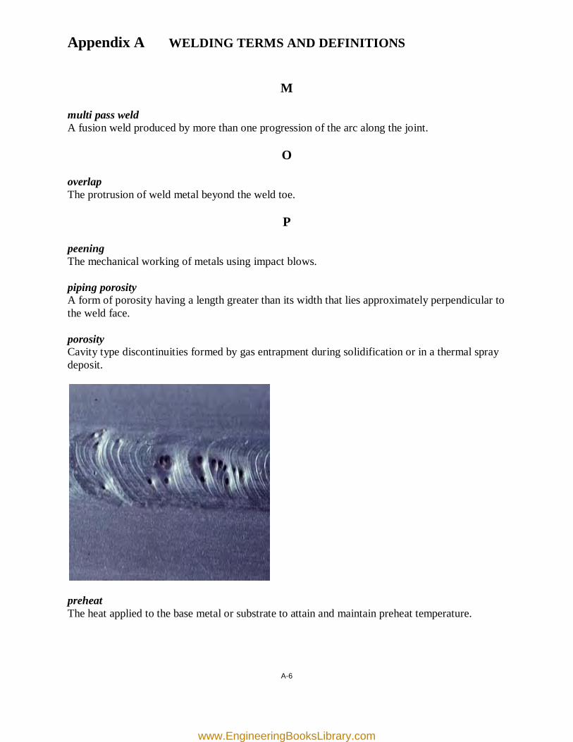
Appendix A WELDING TERMS AND DEFINITIONS
M multi pass weld A fusion weld produced by more than one progression of the arc along the joint.
O overlap The protrusion of weld metal beyond the weld toe.
P peening The mechanical working of metals using impact blows. piping porosity A form of porosity having a length greater than its width that lies approximately perpendicular to the weld face. porosity Cavity type discontinuities formed by gas entrapment during solidification or in a thermal spray deposit.
preheat The heat applied to the base metal or substrate to attain and maintain preheat temperature.
A-6
www.EngineeringBooksLibrary.com
Appendix A WELDING TERMS AND DEFINITIONS
R residual stress Stress present in a joint member or material that is free of external forces or thermal gradients. root face That portion of the groove face within the joint root. root opening A separation at the joint root between the work pieces. runoff weld tab Additional material that extends beyond the end of the joint, on which the weld is started and terminated.
S shielded metal arc welding (SMAW) An arc welding process with an arc between a covered electrode and the weld pool. slag inclusion A discontinuity consisting of slag entrapped in weld metal or at the weld interface. slugging The unauthorized addition of metal, such as a length of rod, to a joint before welding or between passes, often resulting in a weld with incomplete fusion. surface preparation The operations necessary to produce a desired or specified surface condition.
T theoretical throat The distance from the beginning of the joint root perpendicular to the hypotenuse of the largest right triangle that can be inscribed within the cross section of the fillet weld. transverse crack A crack with its major axis oriented approximately perpendicular to the weld axis.
A-7
www.EngineeringBooksLibrary.com
Appendix A WELDING TERMS AND DEFINITIONS
U undercut A groove melted into the base metal adjacent to the weld toe or weld root and left unfilled by the weld metal. underfill A groove weld condition in which the weld face or root surface is below the adjacent surface of the base metal.
W weld A localized coalescence of metals or nonmetals produced either by heating the materials to the welding temperature, with or without the application of pressure, or by the application of pressure alone and with or without the use of filler material. weld face The exposed surface of a weld on the side from which welding was done. weld interface The interface between weld metal and base metal in a fusion weld. weld reinforcement Weld metal in excess of the quantity required to fill a weld groove. weld root The points, shown in cross section, at which the weld metal intersects the base metal and extends furthest into the weld joint. welding A joining process that produces coalescence of materials by heating them to the welding temperature, with or without the application of pressure, or by the application of pressure alone and with or without the use of filler material. weldment An assembly whose component parts are joined by welding. weld toe The junction of the weld face and the base metal.
A-8
www.EngineeringBooksLibrary.com
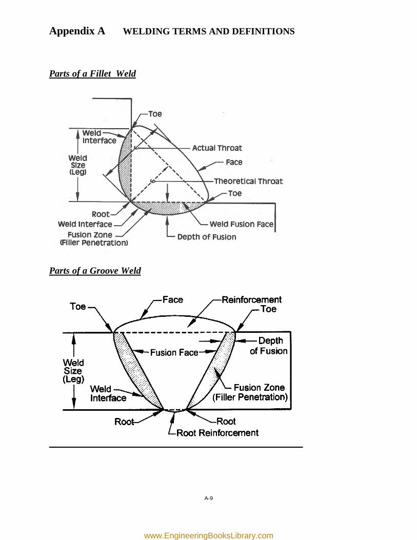
Appendix A WELDING TERMS AND DEFINITIONS
Parts of a Fillet Weld
Parts of a Groove Weld
A-9
www.EngineeringBooksLibrary.com
sssc-s= 1November 1, 1982
Editorial Changes September 1, 2000
SSPC: The Society for Protective Coatings
SURFACE PREPARATION SPECIFICATION NO.1Solvent Cleaning
1. Scope
1.1 This specification covers the requirements for thesolvent cleaning of steel surfaces.
2. Definition
2.1 Solvent cleaning is a method for removing all visibleoil, grease, soil, drawing and cutting compounds, and othersoluble contaminants from steel surfaces.
2.2 It is intended that solvent cleaning be used prior tothe application of paint and in conjunction with surfacepreparation methods specified for the removal of rust, millscale, or paint.
3. Surface Preparation Before and After Sol-vent Cleaning
3.1 Prior to solvent cleaning, remove foreign matter(other than grease and oil) by one or a combination of thefollowing: brush with stiff fiber or wire brushes, abrade,scrape, or clean with solutions of appropriate cleaners,provided such cleaners are followed by a fresh water rinse.
3.2 After solvent cleaning, remove dirt, dust, and othercontaminants from the surface prior to paint application.Acceptable methods include brushing, blow off with clean,dry air, or vacuum cleaning.
4. Methods of Solvent Cleaning
4.1 Remove heavy oil or grease first by scraper. Thenremove the remaining oil or grease by any of the followingmethods:
4.1.1 Wipe or scrub the surface with rags or brusheswetted with solvent. Use clean solvent and clean rags orbrushes for the final wiping.
4.1.2 Spray the surface with solvent. Use clean solventfor the final spraying.
4.1.3 Vapor degrease using stabilized chlorinated hy-drocarbon solvents.
4.1.4 Immerse completely in a tank or tanks of solvent.For the last immersion, use solvent which does not containdetrimental amounts of contaminant.
4.1.5 Emulsion or alkaline cleaners may be used inplace of the methods described. After treatment, wash thesurface with fresh water or steam to remove detrimentalresidues.
4.1.6 Steam clean, using detergents or cleaners andfollow by steam or fresh water wash to remove detrimentalresidues.
5. Inspection
5.1 All work and materials supplied under this specifi-cation shall be subject to timely inspection by the purchaseror his authorized representative. The contractor shall cor-rect such work or replace such material as is found defec-tive under this specification. In case of dispute the arbitra-tion or settlement procedure established in the procure-ment documents, if any, shall be followed. If no arbitrationor settlement procedure is established, the procedure speci-fied by the American Arbitration Association shall be used.
5.2 The procurement documents covering work orpurchase should establish the responsibility for testing andfor any required affidavit certifying full compliance with thespecification.
6. Safety
6.1 All safety requirements stated in this specificationand its component parts apply in addition to any applicablefederal, state, and local rules and requirements. They alsoshall be in accord with instructions and requirements ofinsurance underwriters.
7. Notes*
7.1 While every precaution is taken to ensure that allinformation furnished in SSPC standards and specifica-tions is as accurate, complete, and useful as possible,SSPC cannot assume responsibility nor incur any obliga-tion resulting from the use of any materials, coatings, ormethods specified herein, or of the standard itself.
7.2 A Commentary Section is available and containsadditional information and data relative to this specification.The Surface Preparation Commentary, SSPC-SP COM, isnot part of this specification. The table below lists thesubjects discussed relevant to solvent cleaning and appro-priate Commentary Section.
49
www.EngineeringBooksLibrary.com
SSPC-SP 1November 1, 1982Editorial Changes September 1, 2000
Subject sSPC-SP COM Section
Solvents and Cleaners 5.1.1 through 5.1.3Steam Cleaning 5.1.4Threshold Limit Values 5.1.5Film Thickness 10
"Notes are not requirements of this specification.
50
www.EngineeringBooksLibrary.com
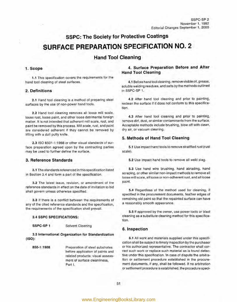
SSPc-SP 2November 1, 1982
Editorial Changes September 1, 2000
SSPC: The Society for Protective Coatings
SURFACE PREPARATION SPECIFICATION NO.2Hand Tool Cleaning
1. Scope
1.1 This specification covers the requirements for thehand tool cleaning of steel surfaces.
2. Definitions
2.1 Hand tool cleaning is a method of preparing steelsurfaces by the use of non-power hand tools.
2.2 Hand tool cleaning removes all loose mill scale,loose rust, loose paint, and other loose detrimental foreignmatter. It is not intended that adherent mill scale, rust, andpaint be removed by this process. Mill scale, rust, and paintare considered adherent if they cannot be removed bylifting with a dull putty knife.
2.3 ISO 8501-1 :1988 or other visual standards of sur-face preparation agreed upon by the contracting partiesmay be used to further define the surface.
3. Reference Standards
3.1 The standards referenced in this specification listedin Section 3.4 and form a part of the specification.
3.2 The latest issue, revision, or amendment of thereference standards in effect on the date of invitation to bidshall govern unless otherwise specified.
3.3 If there is a conflict between the requirements ofany of the cited reference standards and the specification,the requirements of the specification shall prevail.
3.4 SSPC SPECIFICATIONS:
SSPC-SP 1 Solvent Cleaning
3.5 International Organization for Standardization(ISO):
850-1 :1988 Preparation of steel substratesbefore application of paints andrelated products: visual assess-ment of surface cleanliness,Part I.
4. Surface Preparation Before and AfterHand Tool Cleaning
4.1 Before hand tool cleaning, remove visible oil, grease,soluble welding residues, and salts by the methods outlinedin SSPC-SP 1.
4.2 After hand tool cleaning and prior to painting,reclean the surface if it does not conform to this specifica-tion.
4.3 After hand tool cleaning and prior to painting,remove dirt, dust, or similar contaminants from the surface.Acceptable methods include brushing, blow off with clean,dry air, or vacuum cleaning.
5. Methods of Hand Tool Cleaning
5.1 Use impact hand tools to remove stratified rust (rustscale).
5.2 Use impact hand tools to remove all weld slag.
5.3 Use hand wire brushing, hand abrading, handscraping, or other similar non-impact methods to remove allloose mill scale, all loose or non-adherent rust, and all loosepaint.
5.4 Regardless of the method used for cleaning, ifspecified in the procurement documents, feather edges ofremaining old paint so that the repainted surface can havea reasonably smooth appearance.
5.5 If approved by the owner, use power tools or blastcleaning as a substitute cleaning method for this specifica-tion.
6. Inspection
6.1 All work and materials supplied under this specifi-cation shall be subject to timely inspection by the purchaseror his authorized representative. The contractor shall cor-rect such work or replace such material as is found defec-tive under this specification. In case of dispute the arbitra-tion or settlement procedure established in the procure-ment documents, if any, shall be followed. If no arbitrationor settlement procedure is established, the procedure speci-
51
www.EngineeringBooksLibrary.com
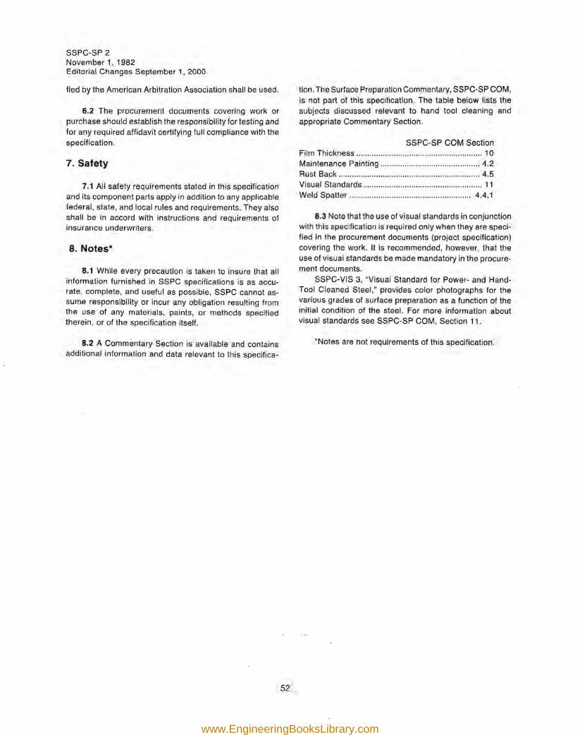
SSPC-SP 2November 1, 1982Editorial Changes September 1, 2000
fied by the American Arbitration Association shall be used.
6.2 The procurement documents covering work orpurchase should establish the responsibility for testing andfor any required affidavit certifying full compliance with thespecification.
7. Safety
7.1 All safety requirements stated in this specificationand its component parts apply in addition to any applicablefederal, state, and local rules and requirements. They alsoshall be in accord with instructions and requirements ofinsurance underwriters.
8. Notes·
8.1 While every precaution is taken to insure that allinformation furnished in SSPC specifications is as accu-rate, complete, and useful as possible, SSPC cannot as-sume responsibility or incur any obligation resulting fromthe use of any materials, paints, or methods specifiedtherein, or of the specification itself.
8.2 A Commentary Section is available and containsadditional information and data relevant to this specifica-
tion. The Surface Preparation Commentary, SSPC-SP COM,is not part of this specification. The table below lists thesubjects discussed relevant to hand tool cleaning andappropriate Commentary Section.
SSPC-SP COM SectionFilm Thickness 10Maintenance Painting 4.2Rust Back 4.5Visual Standards 11Weld Spatter 4.4.1
8.3 Note that the use of visual standards in conjunctionwith this specification is required only when they are speci-fied in the procurement documents (project specification)covering the work. It is recommended, however, that theuse of visual standards be made mandatory in the procure-ment documents.
SSPC-VIS 3, "Visual Standard for Power- and Hand-Tool Cleaned Steel," provides color photographs for thevarious grades of surface preparation as a function of theinitial condition of the steel. For more information aboutvisual standards see SSPC-SP COM, Section 11.
'Notes are not requirements of this specification.
52
www.EngineeringBooksLibrary.com
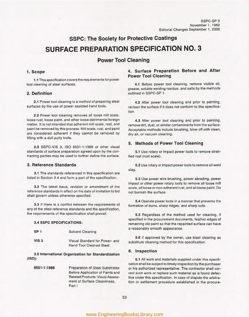
SSPC-SP 3November 1, 1982
, Editorial Changes September 1, 2000
SSPC: The Society for Protective Coatings
SURFACE PREPARATION SPECIFICATION NO.3Power Tool Cleaning
1. Scope
1.1 This specification covers the requirements for powertool cleaning of steel surfaces.
2. Definition
2.1 Power tool cleaning is a method of preparing steelsurfaces by the use of power assisted hand tools.
2.2 Power tool cleaning removes all loose mill scale,loose rust, loose paint, and other loose detrimental foreignmatter. It is not intended that adherent mill scale, rust, andpaint be removed by this process. Mill scale, rust, and paintare considered adherent if they cannot be removed bylifting with a dull putty knife.
2.3 SSPC-VIS 3, ISO 8501-1 :1988 or other visualstandards of surface preparation agreed upon by the con-tracting parties may be used to further define the surface.
3. Reference Standards
3.1 The standards referenced in this specification arelisted in Section 3.4 and form a part of the specification.
3.2 The latest issue, revision or amendment of thereference standards in effect on the date of invitation to bidshall govern unless otherwise specified.
3.3 If there is a conflict between the requirements ofany of the cited reference standards and the specification,the requirements of the specification shall prevail.
3.4 SSPC SPECIFICATIONS:
SP 1 Solvent Cleaning
VIS 3 Visual Standard for Power- andHand Tool Cleaned Steel
3.5 International Organization for Standardization(ISO):
8501·1 :1988 Preparation of Steel SubstratesBefore Application of Paints andRelated Products: Visual Assess-ment of Surface Cleanliness,Part I
4. Surface Preparation Before and AfterPower Tool Cleaning
4.1 Before power tool cleaning, remove visible oil,grease, soluble welding residue, and salts by the methodsoutlined in SSPC-SP 1.
4.2 After power tool cleaning and prior to painting,reclean the surface if it does not conform to this specifica-tion.
4.3 After power tool cleaning and prior to painting,remove dirt, dust, or similar contaminants from the surface.Acceptable methods include brushing, blow off with clean,dry air, or vacuum cleaning.
5. Methods of Power Tool Cleaning
5.1 Use rotary or impact power tools to remove strati-fied rust (rust scale).
5.2 Use rotary or impact power tools to remove all weldslag.
5.3 Use power wire brushing, power abrading, powerimpact or other power rotary tools to remove all loose millscale, all loose or non-adherent rust, and all loose paint. Donot burnish the surface.
5.4 Operate power tools in a manner that prevents theformation of burrs, sharp ridges, and sharp cuts.
5.5 Regardless of the method used for cleaning, ifspecified in the procurement documents, feather edges ofremaining old paint so that the repainted surface can havea reasonably smooth appearance.
5.6 if approved by the owner, use blast cleaning assubstitute cleaning method for this specification.
6. Inspection
6.1 All work and materials supplied under this specifi-cation shall be subject to timely inspection by the purchaseror his authorized representative. The contractor shall cor-rect such work or replace such material as is found defec-tive under this specification. In case of dispute the arbitra-tion or settlement procedure established in the procure-
53
www.EngineeringBooksLibrary.com
SSPC-SP 3November 1, 1982Editorial Changes September 1, 2000
ment documents, if any, shall be followed. If no arbitrationor settlement procedure is established, the procedure speci-fied by the American Arbitration Association shall be used.
6.2 The procurement documents covering work orpurchase should establish the responsibility for testing andfor any required affidavit certifying full compliance with thespecification.
7. Safety
7.1 All safety requirements stated in this specificationand its component parts apply in addition to any applicablefederal, state, and local rules and requirements. They alsoshall be in accord with instructions and requirements ofinsurance underwriters.
8. Notes*
8.1 While every precaution is taken to insure that allinformation furnished in SSPC specifications is as accu-rate, complete, and useful as possible, SSPC cannot as-sume responsibility or incur any obligation resulting fromthe use of any materials, paints, or methods specifiedtherein, or of the specification itself.
8.2 A Commentary Section is available and containsadditional information and data relevant to this specifica-tion.
The Surface Preparation Commentary, SSPC-SP COM,is not part of this specification. The table below lists thesubjects discussed relevant to power tool cleaning andappropriate Commentary Section.
SSPC-SP COM SectionFilm Thickness 10Rust Back 4.5Visual Standards 11Weld Spatter : 4.4.1
8.3 Note that the use of visual standards in conjunctionwith this specification is required only when they are speci-fied in the procurement documents (project specification)covering the work. It is recommended, however, that theuse of visual standards be made mandatory in the procure-ment documents.
SSPC-VIS 3, "Visual Standard for Power- and Hand-Tool Cleaned Steel," provides color photographs for thevarious grades of surface preparation as a function of theinitial condition of the steel. For more information aboutvisual standards, see SSPC-SP COM, Section 11.
'Notes are not requirements of this specification.
54
www.EngineeringBooksLibrary.com
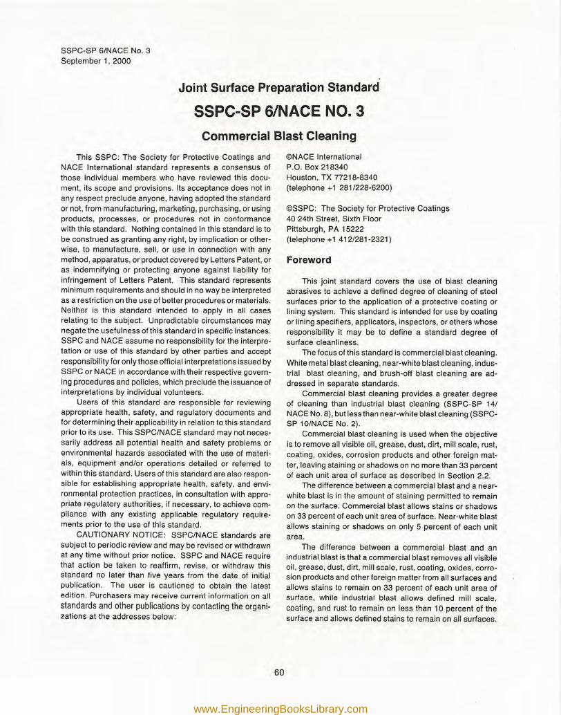
SSPC-SP 6/NACE No.3September 1, 2000
Joint Surface Preparation Standard
ssec-s= 6INACE NO.3Commercial Blast Cleaning
This SSPC: The Society for Protective Coatings andNACE International standard represents a consensus ofthose individual members who have reviewed this docu-ment, its scope and provisions. Its acceptance does not inany respect preclude anyone, having adopted the standardor not, from manufacturing, marketing, purchasing, or usingproducts, processes, or procedures not in conformancewith this standard. Nothing contained in this standard is tobe construed as granting any right, by implication or other-wise, to manufacture, sell, or use in connection with anymethod, apparatus, or product covered by Letters Patent, oras indemnifying or protecting anyone against liability forinfringement of Letters Patent. This standard representsminimum requirements and should in no way be interpretedas a restriction on the use of better procedures or materials.Neither is this standard intended to apply in all casesrelating to the subject. Unpredictable circumstances maynegate the usefulness of this standard in specific instances.SSPC and NACE assume no responsibility for the interpre-tation or use of this standard by other parties and acceptresponsibility for only those official interpretations issued bySSPC or NACE in accordance with their respective govern-ing procedures and policies, which preclude the issuance ofinterpretations by individual volunteers.
Users of this standard are responsible for reviewingappropriate health, safety, and regulatory documents andfor determining their applicability in relation to this standardprior to its use. This SSPC/NACE standard may not neces-sarily address all potential health and safety problems orenvironmental hazards associated with the use of materi-als, equipment and/or operations detailed or referred towithin this standard. Users of this standard are also respon-sible for establishing appropriate health, safety, and envi-ronmental protection practices, in consultation with appro-priate regulatory authorities, if necessary, to achieve com-pliance with any existing applicable regUlatory require-ments prior to the use of this standard.
CAUTIONARY NOTICE: SSPC/NACE standards aresubject to periodic review and may be revised or withdrawnat any time without prior notice. SSPC and NACE requirethat action be taken to reaffirm, revise, or withdraw thisstandard no later than five years from the date of initialpublication. The user is cautioned to obtain the latestedition. Purchasers may receive current information on allstandards and other publications by contacting the organi-zations at the addresses below:
©NACE InternationalP.O. Box 218340Houston, TX 77218-8340(telephone +1 281/228-6200)
©SSPC: The Society for Protective Coatings40 24th Street, Sixth FloorPittsburgh, PA 15222(telephone +1 412/281-2321)
Foreword
This joint standard covers the use of blast cleaningabrasives to achieve a defined degree of cleaning of steelsurfaces prior to the application of a protective coating orlining system. This standard is intended for use by coatingor lining specifiers, applicators, inspectors, or others whoseresponsibility it may be to define a standard degree ofsurface cleanliness.
The focus of this standard is commercial blast cleaning.White metal blast cleaning, near-white blast cleaning, indus-trial blast cleaning, and brush-off blast cleaning are ad-dressed in separate standards.
Commercial blast cleaning provides a greater degreeof cleaning than industrial blast cleaning (SSPC-SP 14/NACE No.8), but less than near-white blast cleaning (SSPC-SP 10/NACE No.2).
Commercial blast cleaning is used when the objectiveis to remove all visible oil, grease, dust, dirt, mill scale, rust,coating, oxides, corrosion products and other foreign mat-ter, leaving staining or shadows on no more than 33 percentof each unit area of surface as described in Section 2.2.
The difference between a commercial blast and a near-white blast is in the amount of staining permitted to remainon the surface. Commercial blast allows stains or shadowson 33 percent of each unit area of surface. Near-white blastallows staining or shadows on only 5 percent of each unitarea.
The difference between a commercial blast and anindustrial blast is that a commercial blast removes all visibleoil, grease, dust, dirt, mill scale, rust, coating, oxides, corro-sion products and other foreign matter from all surfaces andallows stains to remain on 33 percent of each unit area ofsurface, while industrial blast allows defined mill scale.coating, and rust to remain on less than 10 percent of thesurface and allows defined stains to remain on all surfaces.
60
www.EngineeringBooksLibrary.com
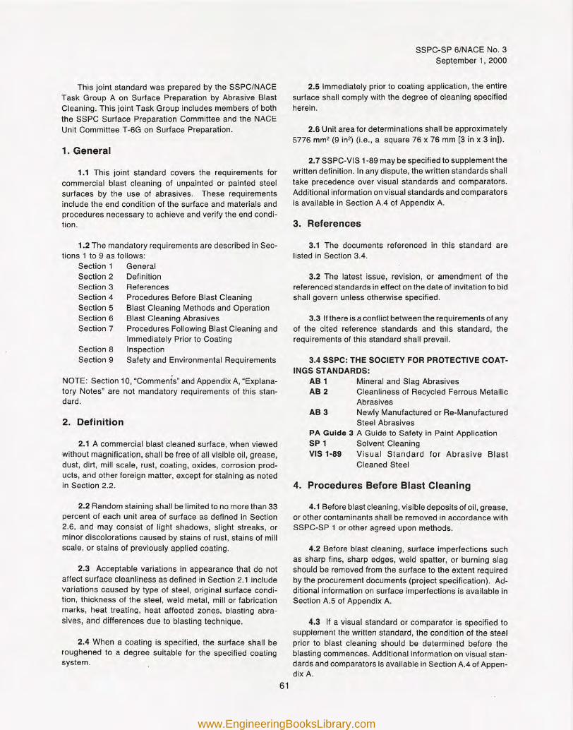
This joint standard was prepared by the SSPC/NACETask Group A on Surface Preparation by Abrasive BlastCleaning. This joint Task Group includes members of boththe SSPC Surface Preparation Committee and the NACEUnit Committee T-6G on Surface Preparation.
1. General
1.1 This joint standard covers the requirements forcommercial blast cleaning of unpainted or painted steelsurfaces by the use of abrasives. These requirementsinclude the end condition of the surface and materials andprocedures necessary to achieve and verify the end condi-tion.
1.2 The mandatory requirements are described in Sec-tions 1 to 9 as follows:
Section 1 GeneralSection 2 DefinitionSection 3 ReferencesSection 4 Procedures Before Blast CleaningSection 5 Blast Cleaning Methods and OperationSection 6 Blast Cleaning AbrasivesSection 7 Procedures Following Blast Cleaning and
Immediately Prior to CoatingSection 8 InspectionSection 9 Safety and Environmental Requirements
NOTE: Section 10, "Comments" and Appendix A, "Explana-tory Notes" are not mandatory requirements of this stan-dard.
2. Definition
2.1 A commercial blast cleaned surface, when viewedwithout magnification, shall be free of all visible oil, grease,dust, dirt, mill scale, rust, coating, oxides, corrosion prod-ucts, and other foreign matter, except for staining as notedin Section 2.2.
2.2 Random staining shall be limited to no more than 33percent of each unit area of surface as defined in Section2.6, and may consist of light shadows, slight streaks, orminor discolorations caused by stains of rust, stains of millscale, or stains of previously applied coating.
2.3 Acceptable variations in appearance that do notaffect surface cleanliness as defined in Section 2.1 includevariations caused by type of steel, original surface condi-tion, thickness of the steel, weld metal, mill or fabricationmarks, heat treating, heat affected zones. blasting abra-sives, and differences due to blasting technique.
2.4 When a coating is specified, the surface shall beroughened to a degree suitable for the specified coatingsystem.
sSPC-SP 6/NACE NO.3September 1, 2000
2.5 Immediately prior to coating application, the entiresurface shall comply with the degree of cleaning specifiedherein.
2.6 Unit area for determinations shall be approximately5776 rnrn" (9 in2) (i.e., a square 76 x 76 mm [3 in x 3 in]).
2.7 SSPC-VIS 1-89 may be specified to supplement thewritten definition. In any dispute, the written standards shalltake precedence over visual standards and comparators.Additional information on visual standards and comparatorsis available in Section AA of Appendix A.
3. References
3.1 The documents referenced in this standard arelisted in Section 304.
3.2 The latest issue, revisron, or amendment of thereferenced standards in effect on the date of invitation to bidshall govern unless otherwise specified.
3.3 If there is a conflict between the requirements of anyof the cited reference standards and this standard, therequirements of this standard shall prevail.
3.4 SSPC: THE SOCIETY FOR PROTECTIVE COAT-INGS STANDARDS:
AB 1 Mineral and Slag AbrasivesAB 2 Cleanliness of Recycled Ferrous Metallic
AbrasivesAB 3 Newly Manufactured or Re-Manufactured
Steel AbrasivesPA Guide 3 A Guide to Safety in Paint ApplicationSP 1 Solvent CleaningVIS 1-89 Visual Standard for Abrasive Blast
Cleaned Steel
4. Procedures Before Blast Cleaning
4.1 Before blast cleaning, visible deposits of oil, grease,or other contaminants shall be removed in accordance withSSPC-SP 1 or other agreed upon methods.
4.2 Before blast cleaning, surface imperfections suchas sharp fins, sharp edges, weld spatter, or burning slagshould be removed from the surface to the extent requiredby the procurement documents (project specification). Ad-ditional information on surface imperfections is available inSection A.5 of Appendix A.
4.3 If a visual standard or comparator is specified tosupplement the written standard, the condition of the steelprior to blast cleaning should be determined before theblasting commences. Additional information on visual stan-dards and comparators is available in Section AA of Appen-dix A.
61
www.EngineeringBooksLibrary.com
ssrc-sr 6/NACE NO.3September 1, 2000
5. Blast Cleaning Methods and Operation
5.1 Clean, dry compressed air shall be used for nozzleblasting. Moisture separators, oil separators, traps, or otherequipment may be necessary to achieve this requirement.
5.2 Any of the following methods of surface preparationmay be used to achieve a commercial blast cleaned surface:
5.2.1 Dry abrasive blasting using compressed air, blastnozzles, and abrasive.
5.2.2 Dry abrasive blasting using a closed-cycle, recir-culating abrasive system with compressed air, blast nozzle,and abrasive, with or without vacuum for dust and abrasiverecovery.
5.2.3 Dry abrasive blasting using a closed cycle, recir-culating abrasive system with centrifugal wheels and abra-sive.
5.3 Other methods of surface preparation (such as wetabrasive blasting) may be used to achieve a commercialblast cleaned surface by mutual agreement between thoseresponsible for performing the work and those responsiblefor establishing the requirements. NOTE: Information onthe use of inhibitors to prevent the formation of rust imme-diately after wet blast cleaning is contained in Section A.9 ofAppendix A.
6. Blast Cleaning Abrasives
6.1 The selection of abrasive size and type shall bebased on the type, grade, and surface condition of the steelto be cleaned, type of blast cleaning system employed, thefinished surface to be produced (cleanliness and rough-ness), and whether the abrasive will be recycled.
6.2 The cleanliness and size of recycled abrasives shallbe maintained to ensure compliance with this specification.
6.3 The blast cleaning abrasive shall be dry and free ofoil, grease, and other contaminants as determined by thetest methods found in SSPC-AS 1, AS 2 and AS 3.
6.4 Any limitations on the use of specific abrasives, thequantity of contaminants, or the degree of allowable embed-ment shall be included in the procurement documents (projectspecification) covering the work, because abrasive embed-ment and abrasives containing contaminants may not beacceptable for some service requirements. NOTE: Addi-tional information on abrasive selection is given in SectionA.2 of Appendix A.
7. Procedures Following Blast Cleaning andImmediately Prior to Coating
7.1 Visible deposits of oil, grease, or other contami-nants shall be removed according to SSPC-SP 1 or anothermethod agreed upon by those parties responsible for estab-lishing the requirements and those responsible for perform-ing the work.
7.2 Dust and loose residues shall be removed fromprepared surfaces by brushing, blowing off with clean, dryair, vacuum cleaning, or other methods agreed upon bythose responsible for establishing the requirements andthose responsible for performing the work. NOTE: Thepresence of toxic metals in the abrasives or paint beingremoved may place restrictions on the methods of cleaningpermitted. Comply with all applicable regulations. Moistureseparators, oil separators, traps, or other equipment may benecessary to achieve clean, dry air.
7.3 After blast cleaning, surface imperfections thatremain (e.g., sharp fins, sharp edges, weld spatter, burningslag, scabs, slivers, etc.) shall be removed to the extentrequired in the procurement documents (project specifica-tion). Any damage to the surface profile resulting from theremoval of surface imperfections shall be corrected to meetthe requirements of Section 2.4. NOTE: Additional informa-tion on surface imperfections is contained in Section A.5 ofAppendix A.
7.4 Any visible rust that forms on the surface of the steelafter blast cleaning shall be removed by recleaning therusted areas to meet the requirements of this standardbefore coating. NOTE: Information on rust-back (re-rust-ing) and surface condensation is contained in Sections A.6,A.7 and A.8 of Appendix A.
8. Inspection
8.1 Work and materials supplied under this standardare subject to inspection by a representative of those re-sponsible for establishing the requirements. Materials andwork areas shall be accessible to the inspector. The proce-dures and times of inspection shall be as agreed upon bythose responsible for establishing the requirements andthose responsible for performing the work.
8.2 Conditions not complying with this standard shall becorrected. In the case of a dispute, an arbitration or settle-ment procedure established in the procurement documents(project specification) shall be followed. If no arbitration orsettlement procedure is established, then a procedure mu-tually agreeable to purchaser and supplier shall be used.
62
www.EngineeringBooksLibrary.com
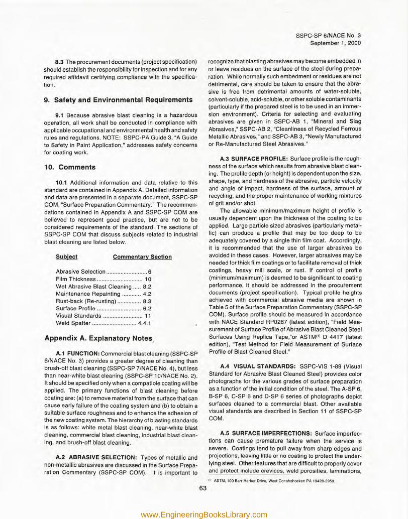
8.3 The procurement documents (project specification)should establish the responsibility for inspection and for anyrequired affidavit certifying compliance with the specifica-tion.
9. Safety and Environmental Requirements
9.1 Because abrasive blast cleaning is a hazardousoperation, all work shall be conducted in compliance withapplicable occupational and environmental health and safetyrules and regulations. NOTE: SSPC-PA Guide 3, "A Guideto Safety in Paint Application," addresses safety concernsfor coating work.
10. Comments
10.1 Additional information and data relative to thisstandard are contained in Appendix A. Detailed informationand data are presented in a separate document, SSPC-SPCOM, "Surface Preparation Commentary." The recommen-dations contained in Appendix A and SSPC-SP COM arebelieved to represent good practice, but are not to beconsidered requirements of the standard. The sections ofSSPC-SP COM that discuss subjects related to industrialblast cleaning are listed below.
Subject Commentary Section
Abrasive Selection 6Film Thickness 10Wet Abrasive Blast Cleaning 8.2Maintenance Repainting 4.2Rust-back (Re-rusting) 8.3Surface Profile 6.2Visual Standards 11Weld Spatter 4.4.1
Appendix A. Explanatory Notes/
A.1 FUNCTION: Commercial blast cleaning (SSPC-SP6/NACE No.3) provides a greater degree of cleaning thanbrush-off blast cleaning (SSPC-SP 7/NACE No.4), but lessthan near-white blast cleaning (SSPC-SP 10/NACE No.2).It should be specified only when a compatible coating will beapplied. The primary functions of blast cleaning beforecoating are: (a) to remove material from the surface that cancause early failure of the coating system and (b) to obtain asuitable surface roughness and to enhance the adhesion ofthe new coating system. The hierarchy of blasting standardsis as follows: white metal blast cleaning, near-white blastcleaning, commercial blast cleaning, industrial blast clean-ing, and brush-off blast cleaning.
A.2 ABRASIVE SELECTION: Types of metallic andnon-metallic abrasives are discussed in the Surface Prepa-ration Commentary (SSPC-SP COM) .. It is important to
SSPC-SP 6/NACE No.3September 1, 2000
recognize that blasting abrasives may become embedded inor leave residues on the surface of the steel during prepa-ration. While normally such embedment or residues are notdetrimental, care should be taken to ensure that the abra-sive is free from detrimental amounts of water-soluble,solvent-soluble, acid-soluble, or other soluble contaminants(particularly if the prepared steel is to be used in an immer-sion environment). Criteria for selecting and evaluatingabrasives are given in SSPC-AB 1, "Mineral and SlagAbrasives," SSPC-AB 2, "Cleanliness of Recycled FerrousMetallic Abrasives," and SSPC-AB 3, "Newly Manufacturedor Re-Manufactured Steel Abrasives."
A.3 SURFACE PROFILE: Surface profile is the rough-ness of the surface which results from abrasive blast clean-ing. The profile depth (or height) is dependent upon the size,shape, type, and hardness of the abrasive, particle velocityand angle of impact, hardness of the surface, amount ofrecycling, and the proper maintenance of working mixturesof grit and/or shot.
The allowable minimum/maximum height of profile isusually dependent upon the thickness of the coating to beapplied. Large particle sized abrasives (particularly metal-lic) can produce a profile that may be too deep to beadequately covered by a single thin film coat. Accordingly,it is recommended that the use of larger abrasives beavoided in these cases. However, larger abrasives may beneeded for thick film coatings or to facilitate removal of thickcoatings, heavy mill scale, or rust. If control of profile(minimum/maximum) is deemed to be significant to coatingperformance, it should be addressed in the procurementdocuments (project specification). Typical profile heightsachieved with commercial abrasive media are shown inTable 5 of the Surface Preparation Commentary (SSPC-SPCOM). Surface profile should be measured in accordancewith NACE Standard RP0287 (latest edition), "Field Mea-surement of Surface Profile of Abrasive Blast Cleaned SteelSurfaces Using Replica Tape,"or ASTM(1) D 4417 (latestedition), 'Test Method for Field Measurement of SurfaceProfile of Blast Cleaned Steel."
A.4 VISUAL STANDARDS: SSPC-VIS 1-89 (VisualStandard for Abrasive Blast Cleaned Steel) provides colorphotographs for the various grades of surface preparationas a function of the initial condition of the steel. The A-SP 6,B-SP 6, C-SP 6 and D-SP 6 series of photographs depictsurfaces cleaned to a commercial blast. Other availablevisual standards are described in Section 11 of SSPC-SPCOM.
A.S SURFACE IMPERFECTIONS: Surface imperfec-tions can cause premature failure when the service issevere. Coatings tend to pull away from sharp edges andprojections, leaving little or no coating to protect the under-lying steel. Other features that are difficult to properly coverand protect include crevices, weld porosities, laminations,
'" ASTM, 100 Sarr Harbor Drive, West Conshohocken PA 19428-2959.
63
www.EngineeringBooksLibrary.com
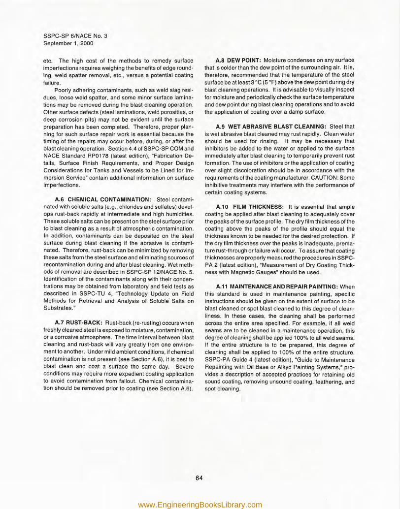
ssr-c-s= 6/NACE NO.3September 1, 2000
etc. The high cost of the methods to remedy surfaceimperfections requires weighing the benefits of edge round-ing, weld spatter removal, etc., versus a potential coatingfailure.
Poorly adhering contaminants, such as weld slag resi-dues, loose weld spatter, and some minor surface lamina-tions may be removed during the blast cleaning operation.Other surface defects (steel laminations, weld porosities, ordeep corrosion pits) may not be evident until the surfacepreparation has been completed. Therefore, proper plan-ning for such surface repair work is essential because thetiming of the repairs may occur before, during, or after theblast cleaning operation. Section 4.4 of SSPC-SP COM andNACE Standard RP0178 (latest edition), "Fabrication De-tails, Surface Finish Requirements, and Proper DesignConsiderations for Tanks and Vessels to be Lined for Im-mersion Service" contain additional information on surfaceimperfections.
A.6 CHEMICAL CONTAMINATION: Steel contami-nated with soluble salts (e.g., chlorides and sulfates) devel-ops rust-back rapidly at intermediate and high humidities.These soluble salts can be present on the steel surface priorto blast cleaning as a result of atmospheric contamination.In addition, contaminants can be deposited on the steelsurface during blast cleaning if the abrasive is contami-nated. Therefore, rust-back can be minimized by removingthese salts from the steel surface and eliminating sources ofrecontamination during and after blast cleaning. Wet meth-ods of removal are described in SSPC-SP 12/NACE NO.5.Identification of the contaminants along with their concen-trations may be obtained from laboratory and field tests asdescribed in SSPC-TU 4, "Technology Update on FieldMethods for Retrieval and Analysis of Soluble' Salts onSubstrates."
A.7 RUST-BACK: Rust-back (re-rusting) occurs whenfreshly cleaned steel is exposed to moisture, contamination,or a corrosive atmosphere. The time interval between blastcleaning and rust-back will vary greatly from one environ-ment to another. Under mild ambient conditions, if chemicalcontamination is not present (see Section A.6), it is best toblast clean and coat a surface the same day. Severeconditions may require more expedient coating applicationto avoid contamination from fallout. Chemical contamina-tion should be removed prior to coating (see Section A.6).
A.S DEW POINT: Moisture condenses on any surfacethat is colder than the dew point of the surrounding air. It is,therefore, recommended that the temperature of the steelsurface be at least 3 DC (5 OF)above the dew point during dryblast cleaning operations. It is advisable to visually inspectfor moisture and periodically check the surface temperatureand dew point during blast cleaning operations and to avoidthe application of coating over a damp surface.
A.9 WET ABRASIVE BLAST CLEANING: Steel thatis wet abrasive blast cleaned may rust rapidly. Clean watershould be used for rinsing. It may be necessary thatinhibitors be added to the water or applied to the surfaceimmediately after blast cleaning to temporarily prevent rustformation. The use of inhibitors or the application of coatingover slight discoloration should be in accordance with therequirements of the coating manufacturer. CAUTION: Someinhibitive treatments may interfere with the performance ofcertain coating systems.
A.10 FILM THICKNESS: It is essential that amplecoating be applied after blast cleaning to adequately coverthe peaks of the surface profile. The dry film thickness of thecoating above the peaks of the profile should equal thethickness known to be needed for the desired protection. Ifthe dry film thickness over the peaks is inadequate, prema-ture rust-through or failure will occur. To assure that coatingthicknesses are properly measured the procedures in SSPC-PA 2 (latest edition), "Measurement of Dry Coating Thick-ness with Magnetic Gauges" should be used.
A.11 MAINTENANCE AND REPAIR PAINTING: Whenthis standard is used in maintenance painting, specificinstructions should be given on the extent of surface to beblast cleaned or spot blast cleaned to this degree of clean-
. liness. In these cases, the cleaning shall be performedacross the entire area specified. For example, if all weldseams are to be cleaned in a maintenance operation, thisdegree of cleaning shall be applied 100% to all weld seams.If the entire structure is to be prepared, this degree ofcleaning shall be applied to 100% of the entire structure.SSPC-PA Guide 4 (latest edition), "Guide to MaintenanceRepainting with Oil Base or Alkyd Painting Systems," pro-vides a description of accepted practices for retaining oldsound coating, removing unsound coating, feathering, andspot cleaning.
64
www.EngineeringBooksLibrary.com
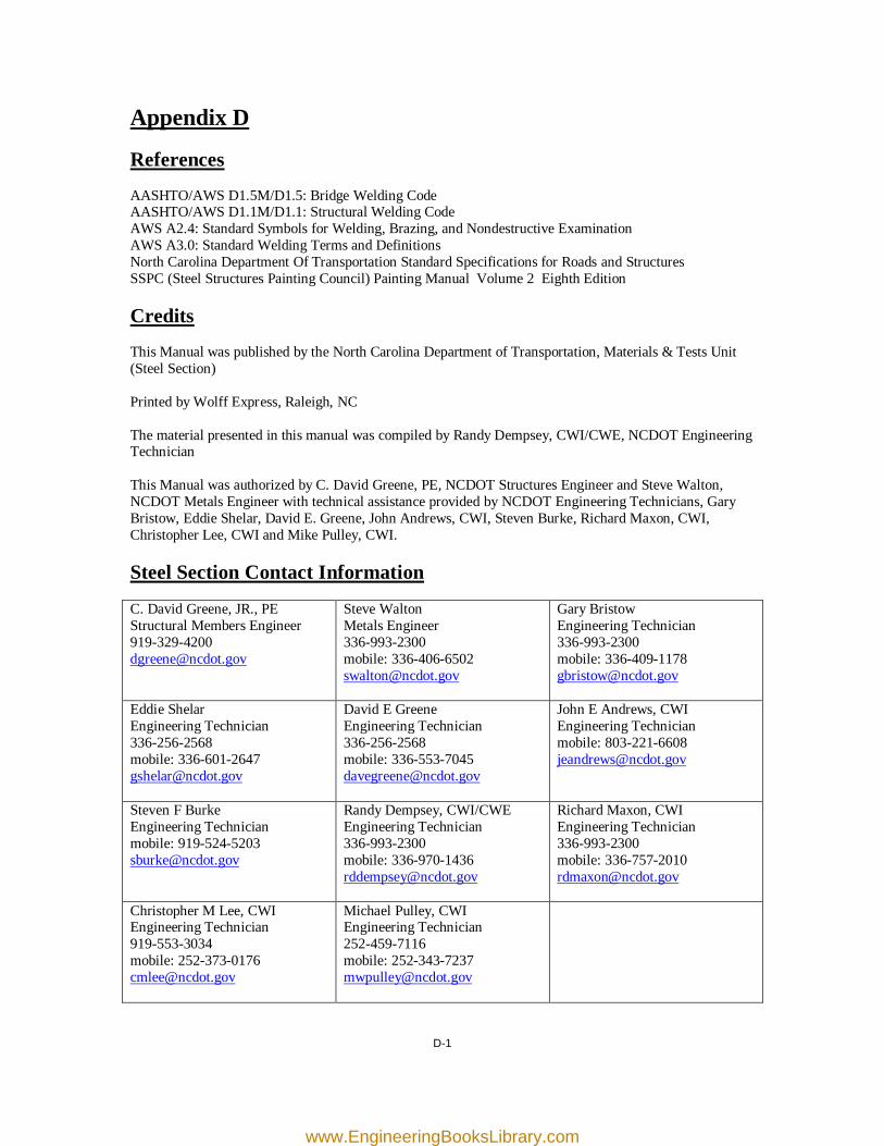
Appendix D
References
AASHTO/AWS D1.5M/D1.5: Bridge Welding Code AASHTO/AWS D1.1M/D1.1: Structural Welding Code AWS A2.4: Standard Symbols for Welding, Brazing, and Nondestructive Examination AWS A3.0: Standard Welding Terms and Definitions North Carolina Department Of Transportation Standard Specifications for Roads and Structures SSPC (Steel Structures Painting Council) Painting Manual Volume 2 Eighth Edition
Credits
This Manual was published by the North Carolina Department of Transportation, Materials & Tests Unit (Steel Section) Printed by Wolff Express, Raleigh, NC The material presented in this manual was compiled by Randy Dempsey, CWI/CWE, NCDOT Engineering Technician This Manual was authorized by C. David Greene, PE, NCDOT Structures Engineer and Steve Walton, NCDOT Metals Engineer with technical assistance provided by NCDOT Engineering Technicians, Gary Bristow, Eddie Shelar, David E. Greene, John Andrews, CWI, Steven Burke, Richard Maxon, CWI, Christopher Lee, CWI and Mike Pulley, CWI.
Steel Section Contact Information
C. David Greene, JR., PE Structural Members Engineer 919-329-4200 [email protected]
Steve Walton Metals Engineer 336-993-2300 mobile: 336-406-6502 [email protected]
Gary Bristow Engineering Technician 336-993-2300 mobile: 336-409-1178 [email protected]
Eddie Shelar Engineering Technician 336-256-2568 mobile: 336-601-2647 [email protected]
David E Greene Engineering Technician 336-256-2568 mobile: 336-553-7045 [email protected]
John E Andrews, CWI Engineering Technician mobile: 803-221-6608 [email protected]
Steven F Burke Engineering Technician mobile: 919-524-5203 [email protected]
Randy Dempsey, CWI/CWE Engineering Technician 336-993-2300 mobile: 336-970-1436 [email protected]
Richard Maxon, CWI Engineering Technician 336-993-2300 mobile: 336-757-2010 [email protected]
Christopher M Lee, CWI Engineering Technician 919-553-3034 mobile: 252-373-0176 [email protected]
Michael Pulley, CWI Engineering Technician 252-459-7116 mobile: 252-343-7237 [email protected]
D-1
www.EngineeringBooksLibrary.com
Appendix E
List of Revisions
The revisions from the May 2010 edition to the 2011 edition of the NCDOT Field Welding Procedures Manual are as follows:
1. Front Cover-Change all photos. 2. Cover Sheet-Change the edition date from "May 2010" to "4th Edition-June 2011". 3. Table of Contents-Change the line spacing and indentation. Add: "Cover Sheet", "Table of Contents", the topics that are presented in the General Information, welding procedures 16 thru 28 (procedures 19 and 20 are only on S drive under Structural Members), Appendix E. 4. Introduction-Add: " Additional information and procedures have been included to assist Bridge Maintenance Personnel with "Repair of Existing Structures". Add information about previous editions. 5. General Information- Reference Standards (note)-Change the letter from "A" to "B" for the appendix reference . Added: AWS D-1.5 Sections 1.1.1 3.2.2, 3.2.4, 3.6.1.1, 3.6.2, 3.6.5, 3.7.2, 3.7.2.1, 3.7.2.2, 33.7.2.3, 3.7.2.4, 3.11.1, 3.11.2, 3.13.5, 4.2.7, 4.5.2 (second portion of the paragraph), 6.26.1, 6.26.1.1, 6.26.1.2, 6.26.1.3, 6.26.1.4, 6.26.1.5, comment about 6.26.1.6, 6.26.1.7, C-6.26.1, C-6.5, a comment about stud welding using automatic equipment, 7.4.1, 7.4.2, 7.5.5, 7.5.5.3, 7.5.5.4. 6. WPS 001-Add the parameters for a 5/32" electrode, changed the interpass maximum to 450⁰, changed the revision number to 4, changed the bevel angle tolerance from -0⁰ to -5⁰. 7. WPS 002-Change the interpass maximum to 450⁰, change the revision number to 4. 8. WPS 003- Change the interpass maximum to 450⁰, change the revision number to 5, add the parameters for a 5/32" electrode, changed the bevel angle tolerance from -0⁰ to -5⁰, omit the root face dimension, change the root opening to 1/4" +5/16" -1/16", change the bevel angle on the horizontal detail to 45⁰. 9. WPS 004-Change the interpass maximum to 450⁰, change the revision number to 4. 10. WPS 005-Change the interpass maximum to 450⁰, change the revision number to 5. 11. WPS 006-Change the interpass maximum to 450⁰, change the revision number to 4. 12. WPS 007-Change the interpass maximum to 450⁰, change the revision number to 4, add the statement in the comments "Remove the protrusion from the bottom of the stud". 13. WPS 008- Change the interpass maximum to 450⁰, change the revision number to 3. 14. WPS 009- Change the interpass maximum to 450⁰, change the revision number to 3, omit the tolerance for the bevel angle. 15. WPS 010- Change the interpass maximum to 450⁰, change the revision number to 3, Change the bevel angle to 60⁰. 16. WPS 011- Change the interpass maximum to 450⁰, change the revision number to 3. 17. WPS 012- Change the interpass maximum to 450⁰, change the revision number to 3, add the parameters for a 5/32" electrode, changed the bevel angle tolerance from -0⁰ to -5⁰, omit the root face dimension, change the root opening to 1/4" +5/16" -1/16", change the bevel angle to 45⁰. 18. WPS 013- Change the interpass maximum to 450⁰, change the revision number to 2. 19. WPS 014- Change the interpass maximum to 450⁰, change the revision number to 2. 20. WPS 015- Change the interpass maximum to 450⁰, change the revision number to 2.
E-1
www.EngineeringBooksLibrary.com
Appendix E
E-2
List of Revisions (cont.) 21. Add welding procedures 016 through 029. 22. Appendix A-Add the following terms and definitions: convexity, porosity, weld, welding. Add a photo for porosity and the figures for "Parts of a Weld". 23. Appendix D-Add D1.1 reference, a paragraph for credits and a table for steel section contact information. 24. Add appendix E, list of revisions. 25. Change all welding parameters from Hobart recommendations to Lincoln recommendations. 26. Add page numbering to the TOC, Introduction, General Information, Welding Procedures, Appendix A and D. 27. Make numerous changes to fonts, spacing, etc. to improve the consistency of the manual. 28. Add photographic illustrations to the welder certification procedures. 29. Add fit-up photographic illustrations for the H-Pile Welding Procedure. 30. A contractor version has been generated that does not include the photo cover, welding procedure photographic illustrations or, due to copy write issues, sspc standards (Appendix B).
www.EngineeringBooksLibrary.com


![Pipe Welding Procedures[1]](https://static.fdocuments.net/doc/165x107/55cf9a13550346d033a05770/pipe-welding-procedures1.jpg)