Fiber Management Systems - West1...
90
FiberGuide ® Fiber Management Systems
Transcript of Fiber Management Systems - West1...

FiberGuide®
Fiber Management Systems

w w w . a d c . c o m • + 1 - 9 5 2 - 9 3 8 - 8 0 8 0 • 1 - 8 0 0 - 3 6 6 - 3 8 9 1
5/
05
•
1
00
56
9Fi
ber
Gu
ide®
Syst
ems
Table of Contents
Introduction . . . . . . . . . . . . . . . . . . . . . . . . . . . . . . . . . . . . . . . . . . . . . . . . . . . . . . . . . . . . . . . . . . . . . . 1Features and Benefits . . . . . . . . . . . . . . . . . . . . . . . . . . . . . . . . . . . . . . . . . . . . . . . . . . . . . . . . . . . . . . 2New Products . . . . . . . . . . . . . . . . . . . . . . . . . . . . . . . . . . . . . . . . . . . . . . . . . . . . . . . . . . . . . . . . . . . . . 3System Description . . . . . . . . . . . . . . . . . . . . . . . . . . . . . . . . . . . . . . . . . . . . . . . . . . . . . . . . . . . . . . . . . 4Patch Cord Densities . . . . . . . . . . . . . . . . . . . . . . . . . . . . . . . . . . . . . . . . . . . . . . . . . . . . . . . . . . . . . . . . 5Applications
Combining System Parts . . . . . . . . . . . . . . . . . . . . . . . . . . . . . . . . . . . . . . . . . . . . . . . . . . . . . . . . . . . 6Downspout Drop Options . . . . . . . . . . . . . . . . . . . . . . . . . . . . . . . . . . . . . . . . . . . . . . . . . . . . . . . . . . 7Express Exit™ Drop Options . . . . . . . . . . . . . . . . . . . . . . . . . . . . . . . . . . . . . . . . . . . . . . . . . . . . . . . . . 8Trumpet Flare Options. . . . . . . . . . . . . . . . . . . . . . . . . . . . . . . . . . . . . . . . . . . . . . . . . . . . . . . . . . . . . 9Raceway Reconfigurations . . . . . . . . . . . . . . . . . . . . . . . . . . . . . . . . . . . . . . . . . . . . . . . . . . . . . . 10-114x12 Island T Feeding Next Generation Frame . . . . . . . . . . . . . . . . . . . . . . . . . . . . . . . . . . . . . . . . . 12Supporting Overhead Systems . . . . . . . . . . . . . . . . . . . . . . . . . . . . . . . . . . . . . . . . . . . . . . . . . . 13-14
2x2 SystemFittings . . . . . . . . . . . . . . . . . . . . . . . . . . . . . . . . . . . . . . . . . . . . . . . . . . . . . . . . . . . . . . . . . . . . . . . 15Downspouts and Attachments . . . . . . . . . . . . . . . . . . . . . . . . . . . . . . . . . . . . . . . . . . . . . . . . . . . . . 16Straight Section and Junction . . . . . . . . . . . . . . . . . . . . . . . . . . . . . . . . . . . . . . . . . . . . . . . . . . . . . . 17
2x6 SystemFittings and Downspouts . . . . . . . . . . . . . . . . . . . . . . . . . . . . . . . . . . . . . . . . . . . . . . . . . . . . . . . 18-19Straight Section and Junction . . . . . . . . . . . . . . . . . . . . . . . . . . . . . . . . . . . . . . . . . . . . . . . . . . . 20-21
4x4 SystemFittings . . . . . . . . . . . . . . . . . . . . . . . . . . . . . . . . . . . . . . . . . . . . . . . . . . . . . . . . . . . . . . . . . . . . . 22-23Downspouts and Attachments . . . . . . . . . . . . . . . . . . . . . . . . . . . . . . . . . . . . . . . . . . . . . . . . . . 24-25Straight Section and Snap-Fit Junction. . . . . . . . . . . . . . . . . . . . . . . . . . . . . . . . . . . . . . . . . . . . . 26-27
4x6 SystemFittings . . . . . . . . . . . . . . . . . . . . . . . . . . . . . . . . . . . . . . . . . . . . . . . . . . . . . . . . . . . . . . . . . . . . . 28-29Downspouts and Attachments . . . . . . . . . . . . . . . . . . . . . . . . . . . . . . . . . . . . . . . . . . . . . . . . . . 30-31Straight Section and Snap-Fit Junction. . . . . . . . . . . . . . . . . . . . . . . . . . . . . . . . . . . . . . . . . . . . . 32-33
4x12 SystemFittings . . . . . . . . . . . . . . . . . . . . . . . . . . . . . . . . . . . . . . . . . . . . . . . . . . . . . . . . . . . . . . . . . . . . . 34-35Downspouts and Attachments . . . . . . . . . . . . . . . . . . . . . . . . . . . . . . . . . . . . . . . . . . . . . . . . . . 36-37Straight Section and Snap-Fit Junction. . . . . . . . . . . . . . . . . . . . . . . . . . . . . . . . . . . . . . . . . . . . . 38-39
Express Exit™ Family . . . . . . . . . . . . . . . . . . . . . . . . . . . . . . . . . . . . . . . . . . . . . . . . . . . . . . . . . . . 40-41Vertical Slotted Duct Systems
1"x 2" and 2"x 2" . . . . . . . . . . . . . . . . . . . . . . . . . . . . . . . . . . . . . . . . . . . . . . . . . . . . . . . . . . . . . . 422"x 4" and 4"x 4" . . . . . . . . . . . . . . . . . . . . . . . . . . . . . . . . . . . . . . . . . . . . . . . . . . . . . . . . . . . . . . 43
Support Kits2x2 System . . . . . . . . . . . . . . . . . . . . . . . . . . . . . . . . . . . . . . . . . . . . . . . . . . . . . . . . . . . . . . . . . 44-452x6, 4x4, 4x6 Systems. . . . . . . . . . . . . . . . . . . . . . . . . . . . . . . . . . . . . . . . . . . . . . . . . . . . . . . . . . . . 464x12 System . . . . . . . . . . . . . . . . . . . . . . . . . . . . . . . . . . . . . . . . . . . . . . . . . . . . . . . . . . . . . . . . . . . 47
Accessories . . . . . . . . . . . . . . . . . . . . . . . . . . . . . . . . . . . . . . . . . . . . . . . . . . . . . . . . . . . . . . . . . . . . 48-50

5/
05
•
1
00
56
9Fi
ber
Gu
ide®
Syst
ems
w w w . a d c . c o m • + 1 - 9 5 2 - 9 3 8 - 8 0 8 0 • 1 - 8 0 0 - 3 6 6 - 3 8 9 1
Dimensional Drawings2x2 System . . . . . . . . . . . . . . . . . . . . . . . . . . . . . . . . . . . . . . . . . . . . . . . . . . . . . . . . . . . . . . . . . 51-522x6 System . . . . . . . . . . . . . . . . . . . . . . . . . . . . . . . . . . . . . . . . . . . . . . . . . . . . . . . . . . . . . . . . . 53-544x4 System . . . . . . . . . . . . . . . . . . . . . . . . . . . . . . . . . . . . . . . . . . . . . . . . . . . . . . . . . . . . . . . . . 55-574x6 System . . . . . . . . . . . . . . . . . . . . . . . . . . . . . . . . . . . . . . . . . . . . . . . . . . . . . . . . . . . . . . . . . 58-594x12 System . . . . . . . . . . . . . . . . . . . . . . . . . . . . . . . . . . . . . . . . . . . . . . . . . . . . . . . . . . . . . . . . 60-62Express Exit Family. . . . . . . . . . . . . . . . . . . . . . . . . . . . . . . . . . . . . . . . . . . . . . . . . . . . . . . . . . . . . . . 63Support Kits. . . . . . . . . . . . . . . . . . . . . . . . . . . . . . . . . . . . . . . . . . . . . . . . . . . . . . . . . . . . . . . . . 64-67
Plenum FiberGuide® SystemSystem Description. . . . . . . . . . . . . . . . . . . . . . . . . . . . . . . . . . . . . . . . . . . . . . . . . . . . . . . . . . . . 68-69Plenum Express Exit Family . . . . . . . . . . . . . . . . . . . . . . . . . . . . . . . . . . . . . . . . . . . . . . . . . . . . . . . . 70Typical Installations . . . . . . . . . . . . . . . . . . . . . . . . . . . . . . . . . . . . . . . . . . . . . . . . . . . . . . . . . . . . . . 71Patch Cord Densities . . . . . . . . . . . . . . . . . . . . . . . . . . . . . . . . . . . . . . . . . . . . . . . . . . . . . . . . . . . . . 722x2 System . . . . . . . . . . . . . . . . . . . . . . . . . . . . . . . . . . . . . . . . . . . . . . . . . . . . . . . . . . . . . . . . . 73-744x6 System . . . . . . . . . . . . . . . . . . . . . . . . . . . . . . . . . . . . . . . . . . . . . . . . . . . . . . . . . . . . . . . . . 75-774x12 System . . . . . . . . . . . . . . . . . . . . . . . . . . . . . . . . . . . . . . . . . . . . . . . . . . . . . . . . . . . . . . . . 78-79Accessories . . . . . . . . . . . . . . . . . . . . . . . . . . . . . . . . . . . . . . . . . . . . . . . . . . . . . . . . . . . . . . . . . 80-81
Index . . . . . . . . . . . . . . . . . . . . . . . . . . . . . . . . . . . . . . . . . . . . . . . . . . . . . . . . . . . . . . . . . . . . . . . . 82-87
Table of Contents

1w w w . a d c . c o m • + 1 - 9 5 2 - 9 3 8 - 8 0 8 0 • 1 - 8 0 0 - 3 6 6 - 3 8 9 1
5/
05
•
1
00
56
9Fi
ber
Gu
ide®
Syst
ems
The Industry’s Most Comprehensive Optical Raceway System
ADC’s FiberGuide® Fiber Management Systems offer the greatest breadth of optical raceway products in theindustry. In response to customer requirements, ADC continues to innovate and improve FiberGuideSystems, adding greater flexibility and driving down installation time to ensure a smooth deployment.
FiberGuide is a raceway system designed to protect and route fiber optic patch cords, multi-fiber cableassemblies and intrafacility fiber cable (IFC) to and from fiber splice enclosures, fiber distribution frames andfiber optic terminal devices. FiberGuide ensures a two-inch minimum bend radius is maintained throughoutthe system. And new tool-less, SnapFit™ junctions, cover options and Plenum Express Exit™ dropssignificantly reduce the amount of time required for installation.
The FiberGuide system is a complete set of products designed and manufactured to ensure total off-frameprotection and ease of use. Basic components include horizontal and vertical straight sections, horizontaland vertical elbows, downspouts, junctions and numerous support hardware and flex-tube kits.
Available in a variety of sizes:
FiberGuide® Fiber Management SystemsIntroduction
2x2 — Ideal for smaller installations or for vertical routing of amaximum of four hundred 2 mm fiberoptic patch cords. All 2x2FiberGuide products are shipped with covers.
2x6 — Designed for height-restricted environments, this robustsystem provides the same support and system flexibility of thetraditional 4-inch-high system while saving 2 inches of overheadspace. It features a maximum capacity of 1,200, 2 mm patch cords.
4x4 — Features the maximum capacity to support 1,600, 2 mmpatch cords. It has been engineered to allow straight sections to beself-supporting over a span of up to 6 feet (1.83 m).
4x6 — Features the same benefits of the 4-inch system and amaximum trough capacity of 2,400, 2 mm patch cords.
4x12 — The largest system in the FiberGuide family, this 12-inch-wide trough has a maximum capacity to support nearly 5,000, 2 mmpatch cords. Perfect for runs over fiber frame lineups and perimeterroutes.
See page 5 for patch cord density tables.

5/
05
•
1
00
56
9Fi
ber
Gu
ide®
Syst
ems
2w w w . a d c . c o m • + 1 - 9 5 2 - 9 3 8 - 8 0 8 0 • 1 - 8 0 0 - 3 6 6 - 3 8 9 1
FiberGuide® Fiber Management SystemsFeatures and Benefits
Features and Benefits
Speed of Installation
FiberGuide® systems feature a variety of products that allow for quick and easy installation. ExpressExit™ drops as well as tool-less products including Snap-Fit™ junctions, snap-on covers and new hingedcover options save valuable time for installers.
Speed of Deployment
The Express Exit system enables new drops to be added or removed quickly and easily. A drop can beadded into a fully loaded raceway in seconds — without cutting.
Raceway Flexibility
FiberGuide features 38 support structures, over 75 fittings, multiple drop options and several othercomponents to suit any application you create.
Fiber Protection
ADC’s broadband expertise translates into maximum protection for your network. Two-inch minimumbend radius is maintained throughout the system regardless of the raceway size.
Strength and Durability
100% raceway reliability — stands up to any challenge.

5/
05
•
1
00
56
9Fi
ber
Gu
ide®
Syst
ems
3w w w . a d c . c o m • + 1 - 9 5 2 - 9 3 8 - 8 0 8 0 • 1 - 8 0 0 - 3 6 6 - 3 8 9 1
FiberGuide® Fiber Management SystemsNew Products
ADC continues to add innovative products to FiberGuide® FiberManagement Systems to ensure they remains the mostcomprehensive solutions for all optical raceway requirements andapplications. These new products increase functionality and flexibilityand are compatible with existing raceway components.
Snap-Fit™ and Hinged Cover Options
To drive down valuable installation time, ADC introduces tool-lessSnap-Fit™ and hinged cover options. Featuring simple, durable plastichardware, these covers install in minutes and require no tools. Thehinged cover option provides easy access, enabling installers andtechnicians to deploy the product quickly and easily. In addition, thecovers do not need to be fully opened for maintenance. (See pages20, 26, 32 & 38.)
Snap-Fit Junction
ADC’s Snap-Fit Junction is the industry’s first completely tool-lessjunction. No additional tools are needed for installation or removal.Quick and easy to install, the FiberGuide Snap-Fit Junction savesvaluable time and money. (See Pages 27, 33 & 39.)
Express Exits™
ADC features a number of innovative Express Exit™ options: Lowprofile, 2-inch and 4-inch options round out this innovative productline, designed to meet your most demanding network requirements.And now Plenum Express Exit systems are also available. By simplysecuring an Express Exit to the sidewall of a Plenum FiberGuidestraight section, jumpers can be permanently or temporarily routed tothe fiber optic terminal (FOT) equipment or fiber frames. No cutting isrequired. Positioning a drop with a member of the Express Exit familygreatly simplifies installation, protects the integrity of existing fibersand increases the overall flexibility of the raceway system (See pages40-41.)
2x6 FiberGuide System
The 2x6 FiberGuide system provides another option to securely routeand protect patch cords. Designed for height-restricted environments,this robust system provides the same support and system flexibility ofthe traditional 4x6 system while saving two inches of overheadspace. A complete set of fittings, straight sections, junction and anExpress Exit are available along with adapters to both the 4x4 and4x6 systems. (See pages 18-21.)
Raceway Reconfiguration Solutions
ADC offers two products to facilitate easy on-site racewayreconfigurations. Available for the 4x4, 4x6 and 4x12 systems, thecut-in “T” (see pages 22, 28 & 34) and the expandable straightsection (see pages 26, 32 & 38) offer the required flexibility tooptimize raceway systems in retrofit applications without jeopardizingthe integrity of existing cables.
Express Exit Family
NEW Hinged Cover System
2x6 FiberGuide System
Cut-in T

5/
05
•
1
00
56
9Fi
ber
Gu
ide®
Syst
ems
4w w w . a d c . c o m • + 1 - 9 5 2 - 9 3 8 - 8 0 8 0 • 1 - 8 0 0 - 3 6 6 - 3 8 9 1
FiberGuide® Fiber Management SystemsSystem Description
FiberGuide® Materials Product StatementThe FiberGuide fiber management system is a UL-listed (E151158) general purpose fiber optic racewaysystem. All FiberGuide products are manufactured from flame-retardant materials. No FiberGuide systemparts contain PVC. The table summarizes the fire-resistant properties of FiberGuide straight sections, moldedparts and flex tube.
Raw Material MeetsUL Requirement
Flame rated: UL94V-0
Flame rated: UL94V-0
Flame rated: UL94V-0
Flame rated: UL94V-0
Flame rated: UL94V-2
Finished Product MeetsUL Requirement
UL94V-0 & UL2024
UL94V-0 & UL2024
UL2024
UL2024
UL2024
FiberGuide Straight Sections(All FiberGuide Systems)
FiberGuide Molded Fittings(All FiberGuide Systems)
FiberGuide Flex Tube (2")
FiberGuide Flex Tube (1")
FiberGuide Flex Tube (7/8")
Note: FiberGuide flex tube complies with the National Electrical Code (NEC) Article 770-51 and Underwriters Laboratory UL2024 requirements for General PurposeFiberOptic Raceways.

5/
05
•
1
00
56
9Fi
ber
Gu
ide®
Syst
ems
5w w w . a d c . c o m • + 1 - 9 5 2 - 9 3 8 - 8 0 8 0 • 1 - 8 0 0 - 3 6 6 - 3 8 9 1
FiberGuide® Fiber Management SystemsPatch Cord Densities
2.0 mm Patch Cords
102
3.0 mm Patch Cords
44
1.7 mm Patch Cords
Recommended capacity takes into consideration random jumper placement into the FiberGuide® system.Maximum density refers to the maximum number of fiber jumpers in a given cross-section of a FiberGuideinstallation. The TracerLight™ Connector Identification System is ADC's newest patch cord solution. It featuresslightly different dimensions than standard patch cords.
RecommendedPatch CordDensity (per in2)
2.0 mm Patch Cords
90
3.0 mm Patch Cords
40
2 inch3 inch4 inch
Trough Pileup
108016202160
480720960
72010801440
320480640
2x2FiberGuide System
360--
160--
3.0 mm
2.0 mm
4x4FiberGuide System
4x6FiberGuide System
MaximumPatch CordDensity (per in2)
142
ADC Recommended Density
Maximum Density
1.7 mm Patch Cords
120
480--
1.7 mm
3.0 mm
2.0 mm
96014401920
1.7 mm
3.0 mm
2.0 mm
144021602880
1.7 mm
4x12FiberGuide System
216032404320
96014401920
3.0 mm
2.0 mm
288043205760
1.7 mm
2 inch3 inch4 inch
Trough Pileup
122418362448
5287921056
81612241632
352528704
408--
176--
3.0 mm
2.0 mm
4x4FiberGuide System
4x6FiberGuide System
568--
3.0 mm
2.0 mm
113617042272
1.7 mm
3.0 mm
2.0 mm
170425563408
1.7 mm
4x12FiberGuide System
244836724896
105615842112
3.0 mm
2.0 mm
340851126816
1.7 mm
2x6FiberGuide System
1080--
480--
3.0 mm
2.0 mm
1440--
1.7 mm
2x2FiberGuide System
1.7 mm
1224--
528--
3.0 mm
2.0 mm
1704--
2x6FiberGuide System
1.7 mm
2 inch 260 780 520 780 15603 inch – – 780 1170 23404 inch – – 1040 1560 3120
Trough Pileup
4x4FiberGuide System
4x6FiberGuide System
4x12FiberGuide System
2x2FiberGuide System
2x6FiberGuide System
TracerLight™ Patch Cords – 65 Patch Cords per in2
5/
05
•
1
00
56
9Fi
ber
Gu
ide®
Syst
ems
6w w w . a d c . c o m • + 1 - 9 5 2 - 9 3 8 - 8 0 8 0 • 1 - 8 0 0 - 3 6 6 - 3 8 9 1
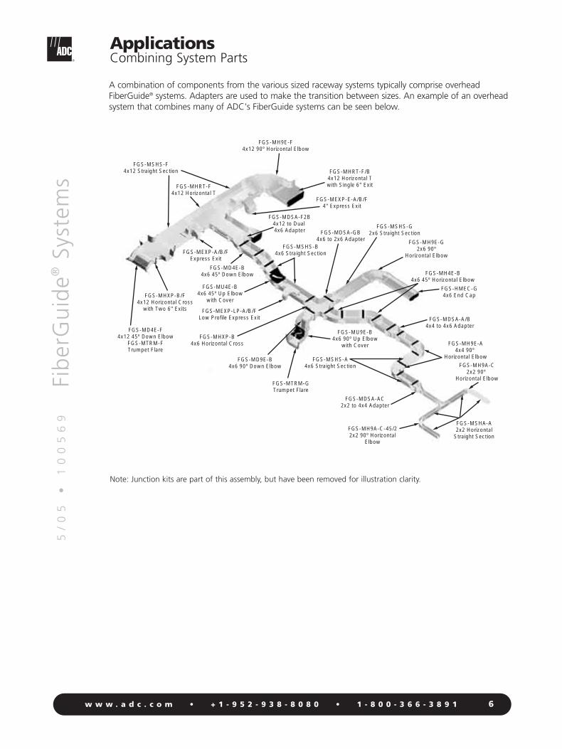
ApplicationsCombining System Parts
A combination of components from the various sized raceway systems typically comprise overheadFiberGuide® systems. Adapters are used to make the transition between sizes. An example of an overheadsystem that combines many of ADC's FiberGuide systems can be seen below.
FGS-MSHA-A2x2 Horizontal
Straight SectionFGS-MH9A-C-45/22x2 90º Horizontal
Elbow
FGS-MDSA-AC2x2 to 4x4 Adapter
FGS-MSHS-A4x6 Straight Section
FGS-MTRM-GTrumpet Flare
FGS-MD9E-B4x6 90º Down Elbow
FGS-MHXP-B4x6 Horizontal Cross
FGS-MEXP-LP-A/B/FLow Profile Express Exit
FGS-MU4E-B4x6 45º Up Elbow
with Cover
FGS-MD4E-B4x6 45º Down Elbow
FGS-MEXP-A/B/FExpress Exit
FGS-MHXP-B/F4x12 Horizontal Cross
with Two 6" Exits
FGS-MD4E-F4x12 45º Down Elbow
FGS-MTRM-FTrumpet Flare
FGS-MSHS-F4x12 Straight Section
FGS-MH9E-F4x12 90º Horizontal Elbow
FGS-MHRT-F/B4x12 Horizontal Twith Single 6" Exit
FGS-MEXP-E-A/B/F4" Express Exit
FGS-MDSA-F2B4x12 to Dual 4x6 Adapter
FGS-MSHS-B4x6 Straight Section
FGS-MDSA-GB4x6 to 2x6 Adapter
FGS-MSHS-G2x6 Straight Section
FGS-MH9E-G2x6 90º
Horizontal Elbow
FGS-MH4E-B4x6 45º Horizontal Elbow
FGS-HMEC-G4x6 End Cap
FGS-MDSA-A/B4x4 to 4x6 Adapter
FGS-MH9E-A4x4 90º
Horizontal Elbow
FGS-MH9A-C2x2 90º
Horizontal Elbow
FGS-MHRT-F4x12 Horizontal T
FGS-MU9E-B4x6 90º Up Elbow
with Cover
Note: Junction kits are part of this assembly, but have been removed for illustration clarity.

5/
05
•
1
00
56
9Fi
ber
Gu
ide®
Syst
ems
7w w w . a d c . c o m • + 1 - 9 5 2 - 9 3 8 - 8 0 8 0 • 1 - 8 0 0 - 3 6 6 - 3 8 9 1
The rigid 2-inch drop option and 2-inch flex tube option are two methods for directing fibers out ofoverhead FiberGuide® downspouts and into optical equipment bays. The rigid system is recommendedbecause it offers excellent bend radius control and ensures a quality fiber backbone installation.
2"x 2" Rigid Drop Option
FGS-MDSP-B4x6 Downspout
FGS-MSHS-B4x6 Straight Section
FGS-MFAW-B4x6 Snap-Fit Junction
FGS-MJWR-C2x2 Junction Kit
FGS-KTW1-C*2x2 Vertical Slotted Duct Kit
FGS-MU4A-C*2x2 45 Up Elbow
FGS-MD4A-C*2x2 45 Down Elbow
FGS-HDSI-AB4x4/4x6 Downspout Insert
FGS-HMEC-B4x6 End Cap Kit
FGS-MDSP-B4x6 Downspout
FGS-MSHS-B4x6 Straight Section
FGS-MFAW-B4x6 Snap-Fit Junction
FGS-HMEC-B4x6 End Cap Kit
FGS-MCDS-ABCover for 4x6 Downspout
FGS-KT03-A14x4 End Cap with one 2" Flex Tube, 5' long
FGS-KTW1-C2x2 Vertical Slotted Duct Kit
*Shown without cover
ApplicationsDownspout Drop Options
2" Flex Tube Drop Option

5/
05
•
1
00
56
9Fi
ber
Gu
ide®
Syst
ems
8w w w . a d c . c o m • + 1 - 9 5 2 - 9 3 8 - 8 0 8 0 • 1 - 8 0 0 - 3 6 6 - 3 8 9 1
The rigid 2-inch drop option and 2-inch flex tube drop option are two methods for delivering patch cordsout of overhead FiberGuide® straight sections and into optical equipment bays. The Express Exit™ allows avertical transition virtually anywhere along FiberGuide straight sections.
FGS-MSHS-B4x6 Straight Section
FGS-MEXP-A/B/F*Express Exit 2x2
FGS-MJWR-C2x2 Junction Kit (4)
FGS-MSHA-C*2x2 Horizontal Solid Straight Section
FGS-KTW1-C*2"x 2" Vertical Slotted Duct Kit
* Shown without Cover
FGS-MD4A-C2x2 45 Down Elbow
FGS-MSHS-B4x6 Straight Section
FGS-MEX1-C-5F2" Flex Tube Attachmentwith 5' of Flex Tube
FGS-MEXP-A/B/F*Express Exit 2x2
FGS-KTW1-C2"x 2" Vertical Slotted Duct Kit
* Shown without Cover
ApplicationsExpress Exit™ Drop Options
2"x 2" Rigid Drop Option 2" Flex Tube Drop Option

5/
05
•
1
00
56
9Fi
ber
Gu
ide®
Syst
ems
9w w w . a d c . c o m • + 1 - 9 5 2 - 9 3 8 - 8 0 8 0 • 1 - 8 0 0 - 3 6 6 - 3 8 9 1
The trumpet flare is recommended at the bottom of a downspout when directing fibers into a fiberdistribution bay. Trumpet flares provide bend radius protection and allow for a large number of fiber patch cords to transition into a fiber bay. A 4x4 trumpet flare is used for the 4x4 and 4x6 downspouts and a 4x6 trumpet flare is used for the 4x12 downspout.
FGS-MHRT-F/B4x12 Horizontal T with single 6" Exit
FGS-MFAW-F4x12 Snap-Fit Junction (2)
FGS-HNTR-F-5/8New Threaded Rod Bracket Kit
FGS-MSHS-F4x12 Horizontal Straight Section
FGS-MTRM-B4x6 Trumpet Flare Kit
FGS-MSHS-B4x6 Straight Section
FGS-MDSP-B4x6 Downspout
FGS-MFAW-B4x6 Snap-Fit Junction (2)
FGS-MTRM-A4x4 Trumpet Flare Kit
Horizontal T and Trumpet Flare Downspout with Trumpet Flare
ApplicationsTrumpet Flare Options
When attaching a straight section or fitting to the exit of a 4x4 or 4x6 downspout, the FGS-MJWR-Ajunction must be used. This junction is only required to connect the vertical part, the FGS-MFAW-Xjunction can be used to connect the horizontal parts.
Shown Assembled
FGS-MFAW-X
FGS-MJWR-A
Exploded View

5/
05
•
1
00
56
9Fi
ber
Gu
ide®
Syst
ems
10w w w . a d c . c o m • + 1 - 9 5 2 - 9 3 8 - 8 0 8 0 • 1 - 8 0 0 - 3 6 6 - 3 8 9 1
Fixture attached to sidewall of raceway Fixture protects cables during cutting of sidewall
Fitting fills gap left by removed sidewall Supplied hardware secures fitting to raceway and completes installation
ADC’s innovative Cut-in T Fitting and Fixture enable on-site raceway modifications without jeopardizing the integrity of installed fibers. Available in 4-, 6-, and 12-inch widths, the cut-in T fitting can be retrofittedto any installed 4-, 6-, and 12-inch straight section using the cut-in T fixture and the hardware suppliedwith the fitting. No special tools are required.
Applications with Raceway ReconfigurationsCut-in T and Fitting

5/
05
•
1
00
56
9Fi
ber
Gu
ide®
Syst
ems
11w w w . a d c . c o m • + 1 - 9 5 2 - 9 3 8 - 8 0 8 0 • 1 - 8 0 0 - 3 6 6 - 3 8 9 1
Applications with Raceway ReconfigurationsExpandable Straight Sections
Raceway system with gap between opposing runs
Completed installation
Expandable straight section extends to connect runs
ADC’s Expandable Straight Section simplifies installation and enhances the overall flexibility of the racewaysystem. The innovative straight section also provides an access point for future reconfigurations. Available in 4-, 6-, and 12-inch widths, the expandable straight section reduces the installation time necessary toconnect opposing runs and provides continuous support for patch cords.

5/
05
•
1
00
56
9Fi
ber
Gu
ide®
Syst
ems
12w w w . a d c . c o m • + 1 - 9 5 2 - 9 3 8 - 8 0 8 0 • 1 - 8 0 0 - 3 6 6 - 3 8 9 1
The 4x12 Island T is designed to be used over the Next Generation Frame (NGF) or FOT storage bay. The4x12 Island T, a horizontal T with spool and factory-installed trumpet flare, channels fiber directly into thevertical cableways below.
4x12 Island T shown installed over an FOT storage bay
Applications4x12 Island T
ADC also offers a 12-inch Island T with recessed spool (see page 33). Designed to be used over theNGF or FOT storage bay, it is used in applications where the drop is positioned high above the frameand protection is required for exiting cables. The part is shipped as a T with a factory-installed, recessedspool. A junction and fitting can then be attached to manage the exiting cables.

5/
05
•
1
00
56
9Fi
ber
Gu
ide®
Syst
ems
13w w w . a d c . c o m • + 1 - 9 5 2 - 9 3 8 - 8 0 8 0 • 1 - 8 0 0 - 3 6 6 - 3 8 9 1
A variety of support kits are available for each FiberGuide® system. Whenever possible, FiberGuide supportkits should be attached to existing hardware (cable racks, digital cableways, existing threaded rods orequipment racks).
2x6, 4x4, 4x6 Systems
4x12 System
Ladder Rack SupportUnistrut SupportAuxiliary Framing Support
New Threaded Rod Bracket Kit
Threaded Rod
Auxiliary Framing Support Kit
Unistrut Nut Kit
Threaded Rod
New Threaded Rod Bracket Kit
Threaded Rod
Threaded Rod
Top SupportC-Bracket
Top of Rack/Cabinet Support
Threaded Rod
Center Support Bracket Kit
New Threaded Rod Bracket Kit
Ladder Rack Bracket Kit
Trapeze Bracket Kit Top of Rack/Cabinet Support Anchor Support
Top Support LowProfile C-Bracket
Threaded Rod
Unistrut Nut Kit
TrapezeBracket Kit
Threaded RodThreaded Rod
Center Support Bracket Kit
ApplicationsSupporting Overhead Systems

5/
05
•
1
00
56
9Fi
ber
Gu
ide®
Syst
ems
14w w w . a d c . c o m • + 1 - 9 5 2 - 9 3 8 - 8 0 8 0 • 1 - 8 0 0 - 3 6 6 - 3 8 9 1
The straight sections on the 4x12 FiberGuide® System are exceptionally strong, making frequent placementof supports beneath them unnecessary. Whenever possible the supports on the 4x12 system should beplaced under the fittings using the mounting bosses as shown (photos 1 and 2). This placement providesthe strongest system and requires the least amount of support hardware to be used. Occasionally it is notpossible to attach the support bracket to the mounting bosses on the fittings; in those instances thevariable fitting support locator can be installed on the bottom of the fitting, allowing the support to beattached anywhere along the fitting bottom (photos 3, 4 and 5). When combining several 4x12 straightsections, it is recommended that support brackets are installed on both sides of each junction.
Variable Fitting Support Locator
Typical 4x12 system installation over a Next Generation Frame Line-up
3
1 2
54
ApplicationsSupporting 4x12 Systems
Note: see page 34 for 4x12 system fittings

5/
05
•
1
00
56
9Fi
ber
Gu
ide®
Syst
ems
15w w w . a d c . c o m • + 1 - 9 5 2 - 9 3 8 - 8 0 8 0 • 1 - 8 0 0 - 3 6 6 - 3 8 9 1
2x2 System Fittings2" H x 2" W
2x2 horizontal Tcover included
2x2 horizontal crosscover included – two 2x2 junctions included; two additional 2x2 junctions required (see p. 17)
2x2 45° horizontal elbow cover included
2x2 90° horizontal elbowcover included
2x2 90° extended horizontal elbowcover included;similar to two 45° horizontal elbows joined
2x2 45° up elbow cover included
2x2 90° up elbow cover included
2x2 45° down elbow cover included
2x2 90° down elbow cover included
2x2 to 4x4 straight adapter cover included
2x2 end cap includes 2x2 junction
Yellow SystemCatalog Number
Orange SystemCatalog Number
Number ofJunctionsDescription
O r d e r i n g I n f o r m a t i o n
FGS-MHTA-C
FGS-MHXP-C
FGS-MH4A-C
FGS-MH9A-C
FGS-MH9A-C-45/2
FGS-MU4A-C
FGS-MU9A-C
FGS-MD4A-C
FGS-MD9A-C
FGS-MDSA-AC
FGS-HMEC-C
FGSO-MHTA-C
FGSO-MHXP-C
FGSO-MH4A-C
FGSO-MH9A-C
FGSO-MH9A-C-45/2
FGSO-MU4A-C
FGSO-MU9A-C
FGSO-MD4A-C
FGSO-MD9A-C
FGSO-MDSA-AC
FGSO-HMEC-C
3
2+2
2
2
2
2
2
2
2
(1) 2x2, (1) 4x4
––
2x2 Horizontal CrossFGS-MHXP-C
2x2 End CapFGS-HMEC-C
2x2 Horizontal T FGS-MHTA-C
2x2 90° ExtendedHorizontal Elbow
FGS-MH9A-C-45/2
2x2 45°Horizontal Elbow
FGS-MH4A-C
2x2 90°Horizontal Elbow
FGS-MH9A-C
2x2 45° Up ElbowFGS-MU4A-C
2x2 45° Down ElbowFGS-MD4A-C
2x2 to 4x4 Straight AdapterFGS-MDSA-AC

5/
05
•
1
00
56
9Fi
ber
Gu
ide®
Syst
ems
16w w w . a d c . c o m • + 1 - 9 5 2 - 9 3 8 - 8 0 8 0 • 1 - 8 0 0 - 3 6 6 - 3 8 9 1
2x2 System Downspouts and Attachments2" H x 2" W
Description
2x2 standard downspout cover included
2x2 extended downspoutcover included
2x2 extended downspout, kit with 2" flex tube
cover included, with 2" flex tube, 2' long
2x2 trumpet flare – includes 2x2 junction
Flex tube clamp kit of 10 attaches 7/8" flex tube to rack
2x2 flex tube attachmentincludes 2" flex tube and a 2x2 junction
5' length10' length15' length
Dual 7/8" flex tube attachmentincludes two lengths of 7/8" flex tube and a 2x2 junction
(2) 5' length(2) 10' length(2) 15' length
Yellow SystemCatalog Number
FGS-MSDS-C
FGS-MDSP-C
FGS-KDH2-C
FGS-MTRM-C
FGS-HSHC-10
FGS-MEX1-C-5FFGS-MEX1-C-10FFGS-MEX1-C-15F
FGS-KT03-CFGS-KT03-C-10FFGS-KT03-C-15F
Orange SystemCatalog Number
FGSO-MSDS-C
FGSO-MDSP-C
FGSO-KDH2-C
FGSO-MTRM-C
FGS-HSHC-10
FGSO-MEX1-C-5FFGSO-MEX1-C-10FFGSO-MEX1-C-15F
FGSO-KT03-CFGSO-KT03-C-10FFGSO-KT03-C-15F
Number ofJunctions
2
1
1
–
–
–––
–––
O r d e r i n g I n f o r m a t i o n
2x2 Standard Downspout FGS-MSDS-C
2x2 Extended Downspout FGS-MDSP-C
FGS-KDH2-CShown Attached to
2x2 FiberGuide System
Dual 7/8" Flex TubeAttachmentFGS-KT03-C
FGS-KT03-C ShownAttached to Downspout
2x2 Trumpet FlareFGS-MTRM-C

5/
05
•
1
00
56
9Fi
ber
Gu
ide®
Syst
ems
17w w w . a d c . c o m • + 1 - 9 5 2 - 9 3 8 - 8 0 8 0 • 1 - 8 0 0 - 3 6 6 - 3 8 9 1
2x2 System Straight Section and Junction2" H x 2" W
Description
2x2 horizontal straight section
6' long, cover included
Orange SystemCatalog Number
FGSO-MSHA-C
Yellow SystemCatalog Number
FGS-MSHA-C
2x2 Horizontal Straight SectionFGS-MSHA-C
Straight Section
O r d e r i n g I n f o r m a t i o n
The 2x2 straight section is a U-shaped trough that provides aprotective raceway for optical fibers. Available in 6-foot lengths, the straight section carries fibers horizontally throughout the system.It can also be installed vertically when routing around obstructions. A warning label is included with each junction kit.
Description
2x2 junction
Orange SystemCatalog Number
FGSO-MJWR-C
Yellow SystemCatalog Number
FGS-MJWR-C2x2 JunctionFGS-MJWR-C
Junction
O r d e r i n g I n f o r m a t i o n
The 2x2 junction is used for mechanically joining FiberGuide® sections.No tools are required for assembly.

5/
05
•
1
00
56
9Fi
ber
Gu
ide®
Syst
ems
18w w w . a d c . c o m • + 1 - 9 5 2 - 9 3 8 - 8 0 8 0 • 1 - 8 0 0 - 3 6 6 - 3 8 9 1
2x6 System Fittings and Downspouts2" H x 6" W
Description
2x6 to 2x2 downspout
2x6 horizontal T
2x6 horizontal cross
2x6 90° horizontal elbow
2x6 90° down elbow
2x6 45° horizontal elbow
2x6 45° up elbow, metal cover included
2x6 45° down elbow
2x6 to 4x4 adapter
2x6 to 4x6 adapter
2x6 trumpet flare
2x6 end cap
2x6 dual 2" flex tube attachment
Number ofJunctions
2
3
4
2
2
2
2
2
(1) 2x6, (1) 4x4
(1) 2x6, (1) 4x6
–
–
–
Yellow SystemCatalog Number
FGS-MDSP-G
FGS-MHRT-G
FGS-MHXP-G
FGS-MH9E-G
FGS-MD9E-G
FGS-MH4E-G
FGS-MU4E-G
FGS-MD4E-G
FGS-MDSA-GA
FGS-MDSA-GB
FGS-MTRM-G
FGS-HMEC-G
FGS-KT03-G-5F
O r d e r i n g I n f o r m a t i o n
Description
Express Exit™ for 2x6 systemincludes base, cover, mounting hardware, and support bracket
Yellow SystemCatalog Number
FGS-MEXP-LP-G
Express Exit 2x6FGS-MEXP-LP-G
Express Exit™
O r d e r i n g I n f o r m a t i o n
Designed for low-ceiling or height-restricted environments, theExpress Exit™ for the 2x6 FiberGuide® system extends only two inchesabove the straight section sidewall. The Express Exit accommodatesup to 150 (3 mm) patch cords, includes removable rear cable guidesfor additional cable management, and features a 2x2 exit opening.It is designed specifically for the 2x6 FiberGuide system and shouldnot be used on any other FiberGuide system.

5/
05
•
1
00
56
9Fi
ber
Gu
ide®
Syst
ems
19w w w . a d c . c o m • + 1 - 9 5 2 - 9 3 8 - 8 0 8 0 • 1 - 8 0 0 - 3 6 6 - 3 8 9 1
2x6 System Fittings and Downspouts2" H x 6" W
2x6 to 2x2 DownspoutFGS-MDSP-G
2x6 Horizontal TFGS-MHRT-G
2x6 Horizontal CrossFGS-MHXP-G
2x6 90° Horizontal ElbowFGS-MH9E-G
2x6 90° Down ElbowFGS-MD9E-G
2x6 45° Horizontal ElbowFGS-MH4E-G
2x6 45° Up ElbowFGS-MU4E-G
Metal Cover Included
2x6 45° Down ElbowFGS-MD4E-G
2x6 to 4x4 AdapterFGS-MDSA-GA
2x6 to 4x6 AdapterFGS-MDSA-GB
2x6 Trumpet FlareFGS-MTRM-G

5/
05
•
1
00
56
9Fi
ber
Gu
ide®
Syst
ems
20w w w . a d c . c o m • + 1 - 9 5 2 - 9 3 8 - 8 0 8 0 • 1 - 8 0 0 - 3 6 6 - 3 8 9 1
2x6 System Straight Section2" H x 6" W
Description
2x6 horizontal straight section, 6' long
New 2x6 hinged cover kit for horizontal straight section
includes three mounting hinges and three clips
6 Inch snap-on cover kit for horizontal straight section
includes six capture clips with mounting clasps
Kit-10 Black Capture Clips*
Yellow SystemCatalog Number
FGS-MSHS-G
FGS-MSNC-B/G
FGS-MSSC-B/G
FGS-DHCP
2x6 Straight SectionFGS-MSHS-G
6 inch snap-on coverFGS-MSSC-B/G
O r d e r i n g I n f o r m a t i o n
The unique four-channel design of the 2x6 FiberGuide® straightsection allows the standard system to be attached to the supportstructure without the need to cut or drill any holes within the trough.This ensures that the patch cords will not come in contact with anyscrew heads or bolts.
NEW Hinged Cover Kit forHorizontal Straight Section
FGS-MSNC-B/G
*see drawings on page 54 for more detail on how capture clips andhinges are used
21
5/
05
•
1
00
56
9Fi
ber
Gu
ide®
Syst
ems
w w w . a d c . c o m • + 1 - 9 5 2 - 9 3 8 - 8 0 8 0 • 1 - 8 0 0 - 3 6 6 - 3 8 9 1
2x6 System Junction2" H x 6" W
Description
2x6 junction
Yellow SystemCatalog Number
FGS-JUNC-G
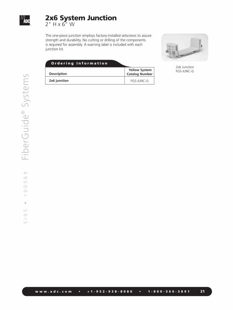
2x6 JunctionFGS-JUNC-G
O r d e r i n g I n f o r m a t i o n
The one-piece junction employs factory-installed setscrews to assurestrength and durability. No cutting or drilling of the components is required for assembly. A warning label is included with eachjunction kit.

5/
05
•
1
00
56
9Fi
ber
Gu
ide®
Syst
ems
22w w w . a d c . c o m • + 1 - 9 5 2 - 9 3 8 - 8 0 8 0 • 1 - 8 0 0 - 3 6 6 - 3 8 9 1
Yellow System Orange System FixedYellow System Snap-on Cover Orange System Snap-on Cover Metal Cover Number of
Description Catalog Number Catalog Number Catalog Number Catalog Number Catalog Number Junctions
4x4 horizontal T FGS-MHRT-A FGS-SHRT-A FGSO-MHRT-A FGSO-SHRT-A FGS-CHRT-A 3
4x4 horizontal cross FGS-MHXP-A FGS-SHXP-A FGSO-MHXP-A FGSO-SHXP-A FGS-CHXP-A 4
4x4 90°horizontal elbow FGS-MH9E-A FGS-SH9E-A FGSO-MH9E-A FGSO-SH9E-A FGS-CH9E-A 2
4x4 90° up elbow FGS-MU9E-A FGS-SU9E-A FGSO-MU9E-A FGSO-SU9E-A 2metal cover included
4x4 90° down elbow FGS-MD9E-A FGS-SD9E-A FGSO-MD9E-A FGSO-SD9E-A FGS-CD9E-A 2
4x4 45°horizontal elbow FGS-MH4E-A FGS-SH4E-A FGSO-MH4E-A FGSO-SH4E-A FGS-CH4E-A 2
4x4 45° up elbow FGS-MU4E-A FGS-SU4E-A FGSO-MU4E-A FGSO-SU4E-A 2metal cover included
4x4 45° down elbow FGS-MD4E-A FGS-SD4E-A FGSO-MD4E-A FGSO-SD4E-A FGS-CD4E-A 2
4x4 to 4x6 straight FGS-MDSA-AB FGS-SDSA-AB FGSO-MDSA-AB FGSO-SDSA-AB FGS-CDSA-AB (1)4x4,(1)4x6adapter
4x4 expandable FGS-MVAR-A FGSO-MVAR-A 2straight section
4x4 cut-in T FGS-MHIS-A FGSO-MHIS-Aassembly hardwareincluded
Cut-in T fixture FGS-MHIS-JIG-A/B/F FGS-MHIS-JIG-A/B/F
4x4 end cap FGS-HMEC-A FGS-HMEC-A
4x4 System Fittings4" H x 4" W
O r d e r i n g I n f o r m a t i o n

5/
05
•
1
00
56
9Fi
ber
Gu
ide®
Syst
ems
23w w w . a d c . c o m • + 1 - 9 5 2 - 9 3 8 - 8 0 8 0 • 1 - 8 0 0 - 3 6 6 - 3 8 9 1
4x4 System Fittings4" H x 4" W
4x4 Horizontal TFGS-MHRT-A
4x4 Horizontal CrossFGS-MHXP-A
4x4 90° Horizontal ElbowFGS-MH9E-A
4x4 45° Horizontal ElbowFGS-MH4E-A
4x4 90° Up ElbowFGS-MU9E-A
Metal Cover Included
4x4 90° Down ElbowFGS-MD9E-A
4x4 45° Up ElbowFGS-MU4E-A
Metal Cover Included
4x4 45° Down ElbowFGS-MD4E-A
4x4 to 4x6 Straight AdapterFGS-MDSA-AB
Cut-in T FixtureFGS-MHIS-JIG-A/B/F
(Shown on straight section)
4x4 Cut-in TFGS-MHIS-A
4x4 Expandable Straight SectionFGS-MVAR-A
Snap-on Plastic Cover(Shown attached to 45° horizontal
elbow with junctions)FGS-SH4E-A
4x4 End CapFGS-HMEC-A

5/
05
•
1
00
56
9Fi
ber
Gu
ide®
Syst
ems
24w w w . a d c . c o m • + 1 - 9 5 2 - 9 3 8 - 8 0 8 0 • 1 - 8 0 0 - 3 6 6 - 3 8 9 1
4x4 System Downspouts and Attachments
Yellow System Orange System Number ofDescription Catalog Number Catalog Number Junctions
4x4 downspout FGS-MDSP-A FGSO-MDSP-A 2*
Cover for 4x4 downspout FGS-MCDS-AB FGSO-MCDS-AB –
4x4 extended downspout FGS-MDSP-EX-A FGSO-MDSP-EX-A 2
Cover for 4x4 extended downspout FGS-MCDS-EX-AB FGSO-MCDS-EX-AB –
4x4 insertable downspout FGS-MDSP-A/I FGSO-MDSP-A/I –
4x4 trumpet flare used on both FGS-MTRM-A FGSO-MTRM-A –4x4 and 4x6 downspouts – no 4" junction kit required
4x4 downspout exit junction kit FGS-MJWR-A FGSO-MJWR-A –
4x4/4x6 downspout insert FGS-HDSI-AB FGS-HDSI-AB –converts bottom of downspout to 2"x 2" without using 2" to 4"adapter, saving vertical space
4" square to 2" round adapter with flex tube – one 4x4 junction kit(FGS-MJWR-A) required to attachto a downspout drop
5' length FGS-ASRI-5F FGSO-ASRI-5F 110' length FGS-ASRI-10F FGSO-ASRI-10F 115' length FGS-ASRI-15F FGSO-ASRI-15F 1
4x4 dual 2" flex tube attachmentno 4x4 junction kit required
(2) 5' length FGS-KT03-A FGSO-KT03-A –(2) 10' length FGS-KT03-A10F FGSO-KT03-A10F –(2) 15' length FGS-KT03-A15F FGSO-KT03-A15F –
4x4 single 2" flex tube attachmentno 4x4 junction kit required
5' length FGS-KT03-A1 FGSO-KT03-A1 –10' length FGS-KT03-A1-10F FGSO-KT03-A1-10F –15' length FGS-KT03-A1-15F FGSO-KT03-A1-15F –
4x4 quad 2" flex tube attachmentno 4x4 junction kit required
(4) 5' length FGS-KT03-A4-5F FGSO-KT03-A4-5F –(4) 10' length FGS-KT03-A4-10F FGSO-KT03-A4-10F –(4) 15' length FGS-KT03-A4-15F FGSO-KT03-A4-15F –
4x4 quad 7/8" flex tube attachmentno 4x4 junction kit required
(4) 5' length FGS-KT07-A4-5F FGSO-KT07-A4-5F –(4) 10' length FGS-KT07-A4-10F FGSO-KT07-A4-10F –(4) 15' length FGS-KT07-A4-15F FGSO-KT07-A4-15F –
*A third junction is needed if drop is to a fitting or straight section. This drop junction must be ajunction type FGS-MJWR-A.
O r d e r i n g I n f o r m a t i o n
An array of 4x4 downspout options are available to feed fiber from overhead straight sectionsinto fiber optic equipment below.

5/
05
•
1
00
56
9Fi
ber
Gu
ide®
Syst
ems
4x4 System Downspouts and Attachments
4x4 Extended DownspoutFGS-MDSP-EX-A
(Shown with and without cover)
4x4 DownspoutFGS-MDSP-A
Cover for 4x4 DownspoutFGS-MCDS-AB
4x4 Downspout Exit Junction Kit
FGS-MJWR-A
4x4 Trumpet FlareFGS-MTRM-A
4x4 Insertable DownspoutFGS-MDSP-A/I
4" Square to 2" RoundAdapter with Flex Tube
FGS-ASRIRequires FGS-MJWR-A
Junction Kit
4x4/4x6 Downspout Insert FGS-HDSI-AB
4x4 Dual 2" Flex Tube Attachment
FGS-KT03-A
4x4 Single 2" Flex Tube Attachment
FGS-KT03-A1
2" Quad Flex Tube Attachment
FGS-KT03-A4
25w w w . a d c . c o m • + 1 - 9 5 2 - 9 3 8 - 8 0 8 0 • 1 - 8 0 0 - 3 6 6 - 3 8 9 1

5/
05
•
1
00
56
9Fi
ber
Gu
ide®
Syst
ems
26w w w . a d c . c o m • + 1 - 9 5 2 - 9 3 8 - 8 0 8 0 • 1 - 8 0 0 - 3 6 6 - 3 8 9 1
4x4 System Straight Section4" H x 4" W
Description
4x4 horizontal straight section6' long
4x4 expandable straight section
NEW 4x4 hinged cover kit for horizontal straight section – includes three mounting hinges and three clips
4x4 snap-on cover kit for horizontal straight section –includes six capture clips with mounting clasps
Vertical spring hinges, kit of 3
Kit - 10 Black Capture Clips*
Kit - 10 Black Capture Clips and 10 Hinges*
4x4 Horizontal Straight Section
FGS-MSHS-A
4x4 Expandable Straight SectionFGS-MVAR-A
The unique four-channel design of the 4x4 FiberGuide® straight section allows the standard system to beattached to the support structure without the need to cut or drill any holes within the trough. This ensuresthat the patch cords will not come in contact with any screw heads or bolts, an important consideration in 4x4 systems where higher cable counts apply increased pressure on patch cords at the bottom of the trough.
NEW 4x4 Hinged Cover forHorizontal Straight Section
FGS-MSNC-A
4x4 Snap-OnCover for Horizontal
Straight SectionFGS-MSSC-A
O r d e r i n g I n f o r m a t i o n
Yellow SystemCatalog Number
FGS-MSHS-A
FGS-MVAR-A
FGS-MSNC-A
FGS-MSSC-A
FGS-HVHG
FGS-DHCP
FGS-DHHC(Yellow Hinge)
Orange SystemCatalog Number
FGSO-MSHS-A
FGSO-MVAR-A
FGSO-MSNC-A
FGSO-MSSC-A
FGS-HVHG
FGS-DHCP
FGSO-DHHC(Orange Hinge)
*see drawings on page 57 for more detail on how capture clips and hinges are used

27
Description
4x4 Snap-Fit Junction
5/
05
•
1
00
56
9Fi
ber
Gu
ide®
Syst
ems
w w w . a d c . c o m • + 1 - 9 5 2 - 9 3 8 - 8 0 8 0 • 1 - 8 0 0 - 3 6 6 - 3 8 9 1
4x4 Snap-Fit Junction4" H x 4" W
The Snap-Fit Junction assembly is available for the 4-inch FiberGuide®
System. The Snap-Fit Junction is a completely tool-less junction. Noadditional tools are required for installation or removal. The junctionexhibits superior holding force and accommodates support brackets. A warning label is included with each junction kit.
4x4 Snap-Fit JunctionFGS-MFAW-A
O r d e r i n g I n f o r m a t i o n
Yellow SystemCatalog Number
FGS-MFAW-A
Orange SystemCatalog Number
FGSO-MFAW-A

5/
05
•
1
00
56
9Fi
ber
Gu
ide®
Syst
ems
28w w w . a d c . c o m • + 1 - 9 5 2 - 9 3 8 - 8 0 8 0 • 1 - 8 0 0 - 3 6 6 - 3 8 9 1
4x6 System Fittings4" H x 6" W
Yellow System Orange System FixedYellow System Snap-on Cover Orange System Snap-on Cover Metal Cover Number of
Description Catalog Number Catalog Number Catalog Number Catalog Number Catalog Number Junctions
4x6 horizontal T FGS-MHRT-B FGS-SHRT-B FGSO-MHRT-B FGSO-SHRT-B FGS-CHRT-B 3
4x6 horizontal cross FGS-MHXP-B FGS-SHXP-B FGSO-MHXP-B FGSO-SHXP-B FGS-CHXP-B 4
4x6 90°horizontal elbow FGS-MH9E-B FGS-SH9E-B FGSO-MH9E-B FGSO-SH9E-B FGS-CH9E-B 2
4x6 90° up elbow FGS-MU9E-B FGSO-MU9E-B 2metal cover included
4x6 90° down elbow FGS-MD9E-B FGS-SD9E-B FGSO-MD9E-B FGSO-SD9E-B FGS-CD9E-B 2
4x6 45°horizontal elbow FGS-MH4E-B FGS-SH4E-B FGSO-MH4E-B FGSO-SH4E-B FGS-CH4E-B 2
4x6 45° up elbow FGS-MU4E-B FGS-SU4E-B FGSO-MU4E-B FGSO-SU4E-B 2metal cover included
4x6 45° down elbow FGS-MD4E-B FGS-SD4E-B FGSO-MD4E-B FGSO-SD4E-B FGS-CD4E-B 2
4x4 to 4x6 straight FGS-MDSA-AB FGS-SDSA-AB FGSO-MDSA-AB FGSO-SDSA-AB FGS-CDSA-AB (1)4x4,(1)4x6adapter
4x12 to single FGS-MDSA-FB FGS-SDSA-FB FGSO-MDSA-FB FGSO-SDSA-FB4x6 adapter
4x6 expandable FGS-MVAR-B FGSO-MVAR-B 2straight section
4x6 cut-in T FGS-MHIS-B FGSO-MHIS-Bassembly hardwareincluded
Cut-in T fixture FGS-MHIS-JIG-A/B/F FGS-MHIS-JIG-A/B/F
4x6 end cap FGS-HMEC-B FGS-HMEC-B
O r d e r i n g I n f o r m a t i o n

5/
05
•
1
00
56
9Fi
ber
Gu
ide®
Syst
ems
29w w w . a d c . c o m • + 1 - 9 5 2 - 9 3 8 - 8 0 8 0 • 1 - 8 0 0 - 3 6 6 - 3 8 9 1
4x6 System Fittings4" H x 6" W
4x6 90° Down ElbowFGS-MD9E-B
4x6 Horizontal TFGS-MHRT-B
4x6 Horizontal CrossFGS-MHXP-B
4x6 90° Horizontal ElbowFGS-MH9E-B
4x6 45° Horizontal ElbowFGS-MH4E-B
4x6 45° Up ElbowFGS-MU4E-B
Cover Included
4x6 45° Down ElbowFGS-MD4E-B
4x6 End CapFGS-HMEC-B
4x6 90° Up ElbowFGS-MU9E-B
Cover Included
4x6 Expandable Straight Section
FGS-MVAR-B
4x6 Cut-in TFGS-MHIS-B
Cut-in T FixtureFGS-MHIS-JIG-A/B/F
(Shown on a straight section)
Snap-on Plastic Cover(Shown attached to 45° horizontal
elbow with junctions)FGS-SH4E-B
4x4 to 4x6 Straight AdapterFGS-MDSA-AB
4x12 to Single 4x6 AdapterFGS-MDSA-FB
Cover: FGS-SDSA-FB

5/
05
•
1
00
56
9Fi
ber
Gu
ide®
Syst
ems
30w w w . a d c . c o m • + 1 - 9 5 2 - 9 3 8 - 8 0 8 0 • 1 - 8 0 0 - 3 6 6 - 3 8 9 1
4x6 System Downspouts and Attachments
Description
4x6 downspoutNote: If a trumpet flare is required use a 4x4 flare(FGS-MTRM-A or FGSO-MTRM-A)
Cover for 4x6 downspout and dual downspout
4x6 extended downspout
Cover for 4x6 extended downspout
4x6 insertable downspout
4x6 dual drop downspout
Trumpet flare for dual drop downspout (kit of 2)
4x6 dual drop downspout with divider
Trumpet flare for dual drop downspout with divider (kit of 2)
4x4 downspout exit junction
4x4/4x6 downspout insert – converts bottom of downspout to 2"x 2" without using 2" to 4" adapter, saving vertical space
4x4 trumpet flare used on both 4x4 and 4x6downspouts — no 4" junction kit required
4x4 square to 2" round adapter with flex tube – one 4x4 junction kit (FGS-MJWR-A)required to attach to a downspout drop
5' length10' length15' length
4x4 dual 2" flex tube attachmentno 4x4 junction kit required
(2) 5' length(2) 10' length(2) 15' length
4x4 single 2" flex tube attachmentno 4x4 junction kit required
5' length10' length15' length
4x4 quad 2" flex tube attachmentno 4x4 junction kit required
(4) 5' length(4) 10' length(4) 15' length
4x4 quad 7/8" flex tube attachmentno 4x4 junction kit required
(4) 5' length(4) 10' length(4) 15' length
Number ofjunction kits
2*
–
2
–
–
2*
–
2
–
–
–
–
111
–––
–––
–––
–––
O r d e r i n g I n f o r m a t i o n
Yellow SystemCatalog Number
FGS-MDSP-B
FGS-MCDS-AB**
FGS-MDSP-EX-B
FGS-MCDS-EX-AB
FGS-MDSP-B/I
FGS-MDSP-2B
FGS-MTRM-2B
FGS-MDSP-2B-IMP
FGS-MTRM-2B-IMP
FGS-MJWR-A
FGS-HDSI-AB
FGS-MTRM-A
FGS-ASRI-5FFGS-ASRI-10FFGS-ASRI-15F
FGS-KT03-AFGS-KT03-A10FFGS-KT03-A15F
FGS-KT03-A1FGS-KT03-A1-10FFGS-KT03-A1-15F
FGS-KT03-A4-5FFGS-KT03-A4-10FFGS-KT03-A4-15F
FGS-KT07-A4-5FFGS-KT07-A4-10FFGS-KT07-A4-15F
Orange SystemCatalog Number
FGSO-MDSP-B
FGSO-MCDS-AB**
FGSO-MDSP-EX-B
FGSO-MCDS-EX-AB
FGSO-MDSP-B/I
FGSO-MDSP-2B
FGSO-MTRM-2B
FGSO-MDSP-2B-IMP
FGSO-MTRM-2B-IMP
FGSO-MJWR-A
FGS-HDSI-AB
FGSO-MTRM-A
FGSO-ASRI-5FFGSO-ASRI-10FFGSO-ASRI-15F
FGSO-KT03-AFGSO-KT03-A10FFGSO-KT03-A15F
FGSO-KT03-A1FGSO-KT03-A1-10FFGSO-KT03-A1-15F
FGSO-KT03-A4-5FFGSO-KT03-A4-10FFGSO-KT03-A4-15F
FGSO-KT07-A4-5FFGSO-KT07-A4-10FFGSO-KT07-A4-15F
An array of 4x6 downspouts and attachments are available to feed fiber from overhead straightsections into fiber optic equipment below. All 4x6 downspouts feature 4-inch exits and attach to the 4-inch exit attachments listed below.
*A 4x4 junction is needed to drop to a fitting or a straight section. This drop junction must be a junction type FGS-MJWR-A.**Dual downspout requires two covers.

5/
05
•
1
00
56
9Fi
ber
Gu
ide®
Syst
ems
31w w w . a d c . c o m • + 1 - 9 5 2 - 9 3 8 - 8 0 8 0 • 1 - 8 0 0 - 3 6 6 - 3 8 9 1
4x6 Dual DownspoutFGS-MDSP-2B
Downspout Exit Junction KitFGS-MJWR-A
4x6 Dual Downspout with Divider
FGS-MDSP-2B-IMP
Trumpet Flare Kit for 4x6 Dual DownspoutFGS-MTRM-2B
Trumpet Flare Kit for DualDownspout with Divider
FGS-MTRM-2B-IMP
4x6 DownspoutFGS-MDSP-B
Cover for 4x6 DownspoutFGS-MCDS-AB
4x6 Extended DownspoutFGS-MDSP-EX-B(Shown with and
without cover)
4x6 Insertable DownspoutFGS-MDSP-B/I
4x4 Trumpet Flare KitFGS-MTRM-A
4x6 System Downspouts and Attachments
4" Square to 2" RoundAdapter with Flex Tube
FGS-ASRIRequires FGS-MJWR-A
Junction Kit
4x4/4x6 Downspout Insert FGS-HDSI-AB
4x4 Dual 2" Flex Tube Attachment
FGS-KT03-A
4x4 Single 2"Flex Tube Attachment
FGS-KT03-A1
2" Quad Flex Flex Tube Attachment
FGS-KT03-A4

5/
05
•
1
00
56
9Fi
ber
Gu
ide®
Syst
ems
32w w w . a d c . c o m • + 1 - 9 5 2 - 9 3 8 - 8 0 8 0 • 1 - 8 0 0 - 3 6 6 - 3 8 9 1
4x6 System Straight Section and Junction4" H x 6" W
Description
4x6 horizontal straight section, 6' long
4x6 expandable straight section
4x6 slack storage straight section
NEW 4x6 hinged cover kit for horizontal straight section – includes three mounting hinges and three clips
6" snap-on cover kit for horizontal straight section –includes six quick knobs with mounting clasps
Vertical spring hinges
Kit-10 Black Capture Clips
Kit-10 Black Capture Clips and 10 Hinges
Orange SystemCatalog Number
FGSO-MSHS-B
FGSO-MVAR-B
FGSO-MSHS-STOR-B
FGSO-MSNC-B/G
FGSO-MSSC-B/G
FGS-HVHG
FGS-DHCP
FGSO-DHHC(orange hinge)
Yellow SystemCatalog Number
FGS-MSHS-B
FGS-MVAR-B
FGS-MSHS-STOR-B
FGS-MSNC-B/G
FGS-MSSC-B/G
FGS-HVHG
FGS-DHCP
FGS-DHHC(yellow hinge)
4x6 HorizontalStraight Section
FGS-MSHS-B
NEW Hinged Cover Kit for HorizontalStraight SectionFGS-MSNC-B/G
The unique four-channel design of the 4x6 FiberGuide® straight sections allows the standard system to beattached to the support structure without the need to cut or drill any holes within the trough. This ensuresthat the patch cords will not come in contact with any screw heads or bolts, an important consideration in 4x6systems where higher cable counts apply increased pressure on patch cords at the bottom of the trough.
4x6 ExpandableStraight Section
FGS-MVAR-B
6" Snap-on Coverfor Horizontal
Straight SectionFGS-MSSC-B/G
O r d e r i n g I n f o r m a t i o n
Straight Section
*see drawings on page 59 for more detail on how capture clips and hinges are used

33
5/
05
•
1
00
56
9Fi
ber
Gu
ide®
Syst
ems
w w w . a d c . c o m • + 1 - 9 5 2 - 9 3 8 - 8 0 8 0 • 1 - 8 0 0 - 3 6 6 - 3 8 9 1
4x6 Snap-Fit Junction4" H x 6" W
The Snap-Fit Junction assembly is available for the 6-inch FiberGuide®
system. The new junction is a completely tool-less junction. No additionaltools are required for installation or removal. The Snap-Fit Junctionexhibits superior holding force and accommodates support brackets.A warning label is included with each junction kit.
Description
4x6 Snap-Fit Junction
Orange SystemCatalog Number
FGSO-MFAW-B
Yellow SystemCatalog Number
FGS-MFAW-B
4x6 Snap-Fit JunctionFGS-MFAW-B
O r d e r i n g I n f o r m a t i o n

5/
05
•
1
00
56
9Fi
ber
Gu
ide®
Syst
ems
34w w w . a d c . c o m • + 1 - 9 5 2 - 9 3 8 - 8 0 8 0 • 1 - 8 0 0 - 3 6 6 - 3 8 9 1 34
4x12 System Fittings4" H x 12" W
Description
4x12 horizontal T
4x12 horizontal cross
4x12 90° horizontal elbow
4x12 90° down elbow
4x12 45° horizontal elbow
4x12 45° up elbow
4x12 45° down elbow
4x12 horizontal T with single6" exit
4x12 horizontal cross withtwo 6" exits
4x12 to dual 4x6 adapter
4x12 to single 4x6 adapter
4x12 to 4x6 right adapterincludes fastening hardware
Fixed metal cover for right adapter
4x12 to 4x6 left adapterincludes fastening hardware
Fixed metal cover for left adapter
4x12 end cap
4x12 expandable straight section
4x12 cut-in T
Cut-in T fixture
Variable support locator kitsEach kit contains all necessary mounting hardware.
Fitting sold separatelyKit for:FGS-MDSP-FFGS-MHRT-FFGS-MHXP-FFGS-MH9E-FFGS-MHRT-F/BFGS-MHXP-B/F
Yellow SystemCatalog Number
FGS-MHRT-F
FGS-MHXP-F
FGS-MH9E-F
FGS-MD9E-F
FGS-MH4E-F
FGS-MU4E-F
FGS-MD4E-F
FGS-MHRT-F/B
FGS-MHXP-B/F
FGS-MDSA-F2B
FGS-MDSA-FB
FGS-MDSA-FB-R
FGS-VDSA-FB-R
FGS-MDSA-FB-L
FGS-VDSA-FB-L
FGS-HMEC-F
FGS-MVAR-F
FGS-MHIS-F
FGS-MHIS-JIG-A/B/F
FGS-MDSP-F-VSFGS-MHRT-F-VSFGS-MHXP-F-VSFGS-MH9E-F-VSFGS-MHRT-F/B-VSFGS-MHXP-B/F-VS
Number ofJunctions
3
4
2
2
2
2
2
(2) 4x12,(1)4x6
(2)4x12, (2)4x6
(1)4x12,(2)4x6
(1)4x12, (1)4x6
–
–
–
–
–
2
–
–
Yellow SystemSnap-on CoverCatalog Number
FGS-SHRT-F
FGS-SHXP-F
FGS-SH9E-F
FGS-SD9E-F
FGS-SH4E-F
FGS-SU4E-F
FGS-SD4E-F
FGS-SHRT-F/B
FGS-SHXP-B/F
FGS-SDSA-F2B
FGS-SDSA-FB
Orange SystemSnap-on CoverCatalog System
FGSO-SHRT-F
FGSO-SHXP-F
FGSO-SH9E-F
FGSO-SD9E-F
FGSO-SH4E-F
FGSO-SU4E-F
FGSO-SD4E-F
FGSO-SHRT-F/B
FGSO-SHXP-B/F
FGSO-SDSA-F2B
FGSO-SDSA-FB
Snap-on cover installation
O r d e r i n g I n f o r m a t i o n
Orange SystemCatalog Number
FGSO-MHRT-F
FGSO-MHXP-F
FGSO-MH9E-F
FGSO-MD9E-F
FGSO-MH4E-F
FGSO-MU4E-F
FGSO-MD4E-F
FGSO-MHRT-F/B
FGSO-MHXP-B/F
FGSO-MDSA-F2B
FGSO-MDSA-F
FGS-MDSA-FB-R
FGS-VDSA-FB-R
FGS-MDSA-FB-L
FGS-VDSA-FB-L
FGS-HMEC-F
FGSO-MVAR-F
FGSO-MHIS-F
FGS-MHIS-JIG-A/B/F
FGS-MDSP-F-VSFGS-MHRT-F-VSFGS-MHXP-F-VSFGS-MH9E-F-VSFGS-MHRT-F/B-VSFGS-MHXP-B/F-VS

4x12 to 4x6 Adapter – RightFGS-MDSA-FB-R
5/
05
•
1
00
56
9Fi
ber
Gu
ide®
Syst
ems
35w w w . a d c . c o m • + 1 - 9 5 2 - 9 3 8 - 8 0 8 0 • 1 - 8 0 0 - 3 6 6 - 3 8 9 1 35
4x12 System Fittings4" H x 12" W
4x12 Horizontal TFGS-MHRT-F
4x12 Horizontal Cross FGS-MHXP-F
4x12 90° Horizontal ElbowFGS-MH9E-F
4x12 90° Down ElbowFGS-MD9E-F
4x12 45° Horizontal ElbowFGS-MH4E-F
4x12 45° Up ElbowFGS-MU4E-F
4x12 45° Down ElbowFGS-MD4E-F
4x12 Horizontal T with Single 6" ExitFGS-MHRT-F/B
4x12 Horizontal Crosswith Two 6" Exits
FGS-MHXP-B/F
4x12 End CapFGS-HMEC-F
4x12 to Dual 4x6 AdapterFGS-MDSA-F2B
4x12 to Single 4x6 AdapterFGS-MDSA-FB
4x12 Cut-in TFGS-MHIS-F
4x12 to 4x6 Adapter – LeftFGS-MDSA-FB-L
4x12 Expandable Straight Section
FGS-MVAR-F
Cut-in T FixtureFGS-MHIS-JIG-A/B/F
(Shown on a straight section)

Description
4x12 downspout
4X12 Insertable downspout
Cover for 4x12 downspout
4x12 trumpet flare
4x12 downspout with rear T
4x12 Island T with spool and factory –installed trumpet flare designed for use over ADC Next Generation Frame Storage Bay
4x12 Island T with trumpet and dividing spool –designed for use over ADC 600 mm wide Next Generation Frame – Variable Support Locator Kit included
4x12 Island T with recessed dividing spool4x6 dual 2" flex tube attachment
5' length10' length15' length
4x6 trumpet flare kitused on 4x12 downspouts
4x12 to 4x4 downspout converterconverts downspout openingto accept 4x4 slotted duct
4x12 to 2x2 downspout converter
Number ofJunction Kits
2*
–
–
3*
2
2
3
–––
–
–
–
Yellow SystemCatalog Number
FGS-MDSP-F
FGS-MDSP-F/I
FGS-SDSP-F
FGS-MTRM-F
FGS-MDRT-F
FGS-ISLAND-F
FGS-ISLAND-F-513
FGS-ISLAND3-F
FGS-KT03-BFGS-KT03-B-10FFGS-KT03-B-15F
FGS-MTRM-B
FGS-HDSI-F/D
FGS-HDSI-F/C
Orange SystemCatalog Number
FGSO-MDSP-F
FGSO-MDSP-F/I
FGSO-SDSP-F
FGSO-MTRM-F
FGSO-MDRT-F
FGSO-ISLAND-F
FGSO-ISLAND-F-513
FGSO-ISLAND3-F
FGSO-KT03-BFGSO-KT03-B-10FFGSO-KT03-B-15F
FGSO-MTRM-B
FGS-HDSI-F/D
FGS-HDSI-F/C
5/
05
•
1
00
56
9Fi
ber
Gu
ide®
Syst
ems
36w w w . a d c . c o m • + 1 - 9 5 2 - 9 3 8 - 8 0 8 0 • 1 - 8 0 0 - 3 6 6 - 3 8 9 1
An array of 4x12 downspouts and attachments are available to feed fiber from overhead straight sectionsinto fiber optic equipment below. The 4x12 downspout features a 4x6 exit and accepts the 4x6 exitattachments listed below.
*An additional junction is needed if drop is to fitting or straight section. This 4x6 junction must be ajunction type FGS-MFAW-B.
4x12 System Downspouts and Attachments
O r d e r i n g I n f o r m a t i o n

5/
05
•
1
00
56
9Fi
ber
Gu
ide®
Syst
ems
37w w w . a d c . c o m • + 1 - 9 5 2 - 9 3 8 - 8 0 8 0 • 1 - 8 0 0 - 3 6 6 - 3 8 9 1
4x6 Dual 2" Flex Tube Attachment
FGS-KT03-B
4x6 Trumpet Flare Kit ShownAlone and Attached to
4x12 DownspoutFGS-MTRM-B
4x12 to 4x4 Downspout Converter
FGS-HDSI-F/D
The FGS-HSDI-F/D Attached to Both the 4x12 Downspout and the 4x4 Slotted Duct without the Use of Hardware
4x12 DownspoutFGS-MDSP-F
Cover for 4x12 DownspoutFGS-SDSP-F
4x12 Trumpet FlareFGS-MTRM-F
4x12 Island T with RecessedDividing SpoolFGS-ISLAND3-F
(Shown with 12" Junction,90º Down Elbow and
Trumpet Flare)
4x12 Downspout with Rear TFGS-MDRT-F
4x12 Island TFGS-ISLAND-F
4x12 System Downspouts and Attachments

5/
05
•
1
00
56
9Fi
ber
Gu
ide®
Syst
ems
38w w w . a d c . c o m • + 1 - 9 5 2 - 9 3 8 - 8 0 8 0 • 1 - 8 0 0 - 3 6 6 - 3 8 9 1
4x12 System Straight Section4" H x 12" W
The unique nine-channel design of the 4x12 FiberGuide® straight sections provides unmatched strength andallows the attachment of support structure without the need to cut or drill holes within the raceway. Thisensures that the patch cords will not come in contact with any screw heads or bolts, an importantconsideration in 4x4, 4x6, and 4x12 systems where higher cable counts apply increased pressure on thepatch cords at the bottom of the raceway.
The 4x12 system covers feature a snap-on design. This allows the cover to be used in environments withlimited headroom. Two 3-foot cover sections come with each order, making it easy for one person toremove the covers. Each cover kit includes a tether kit. The straight section covers are designed to be placedover the 4x12 downspouts, speeding installation time by reducing the number of measurements and cutsthat need to be made.
4x12 Horizontal Straight SectionFGS-MSHS-F
4x12 Horizontal Straight SectionCover (includes two 3' Lengths
and Tethering Hardware)FGS-MSSC-F
4x12 Straight Section Cover inTethered Position
4x12 Straight Section CoverAttached to Straight Section
Yellow System Orange System
Description Catalog Number Catalog Number
4x12 horizontal straight section, 6' long FGS-MSHS-F FGSO-MSHS-F
4x12 expandable straight section FGS-MVAR-F FGSO-MVAR-F
4x12 slack storage straight section FGS-MSHS-STOR-F FGSO-MSHS-STOR-F
New 4x12 hinged cover kit FGS-MSNC-F FGSO-MSNC-Ffor horizontal straight section, includes five mounting hinges and three clips
Kit-10 black capture clips* FGS-DHCP FGSO-DHCP
4x12 snap-on cover kit* FGS-MSSC-F FGSO-MSSC-Ffor horizontal straight section includes two 3' covers, optional tethering kit
O r d e r i n g I n f o r m a t i o n
4x12 Expandable Straight Section
FGS-MVAR-F
*see drawings on page 62 for more detail on how capture clips and hinges are used
New 12” Hinged Cover forHorizontal Straight Section
FGS-MSNC-F

5/
05
•
1
00
56
9Fi
ber
Gu
ide®
Syst
ems
39w w w . a d c . c o m • + 1 - 9 5 2 - 9 3 8 - 8 0 8 0 • 1 - 8 0 0 - 3 6 6 - 3 8 9 1
The new Snap-Fit™ Junction is available for the 12-inch (30-48 cm)FiberGuide® system. The Snap-Fit Junction is a completely tool-lessjunction. No additional tools are required for installation or removal.The Snap-Fit Junction exhibits superior holding force andaccommodates support brackets.
Description
4x12 Snap-Fit Junction FGSO-MFAW-FFGS-MFAW-F
Yellow SystemCatalog Number
Orange SystemCatalog Number
O r d e r i n g I n f o r m a t i o n
4x12 Snap-Fit Junction4" H x 12" W
4x12 Snap-Fit JunctionFGS-MFAW-F

5/
05
•
1
00
56
9Fi
ber
Gu
ide®
Syst
ems
40w w w . a d c . c o m • + 1 - 9 5 2 - 9 3 8 - 8 0 8 0 • 1 - 8 0 0 - 3 6 6 - 3 8 9 1
Express Exit™ FamilyFor 4x4, 4x6, and 4x12 Systems
Express Exit Family
ADC’s patented* Express Exit™ family accommodates various racewayenvironments and applications. By simply securing an Express Exit tothe sidewall of any 4x4, 4x6, or 4x12 FiberGuide® straight section,jumpers can be permanently or temporarily routed to fiber opticterminal (FOT) equipment below. No cutting of the FiberGuide systemis required. Positioning a drop with a member of the Express Exit familygreatly simplifies installation, protects the integrity of fibers alreadypresent in the raceway, and increases overall flexibility of the racewaysystem. All Express Exits guarantee 2-inch bend radius protection.
Express Height Above Exit 3 mm Patch 2 mm Patch Hinged Exit FinExit Style Sidewall Opening Cord Capacity Cord Capacity Rear Cover Inserts
2-Inch Express Exit 4" 2" x 2"1 150 350 No No
Low-Profile Express Exit 2" 2" x 2"1 150 350 No No
4-Inch Express Exit 4" 4" x 4"2 300 700 Yes Yes
1Accepts all standard 2"x 2" attachments.2Accepts all standard 4"x 4" attachments.
*Other patents pending
Description
4-Inch Express Exit includes base, base cover, mounting hardware, support bracket, and exit inserts
4-Inch Express Exit rear hinged cover kitone 4x4, 4x6, 4x12 rear hinged cover
4-Inch Express Exit rear hinged cover for 4x4 raceway
4-Inch Express Exit rear hinged cover for 4x6 raceway
4-Inch Express Exit rear hinged cover for 4x12 raceway
Orange SystemCatalog Number
FGSO-MEXP-E-A/B/F
FGSO-MEXC-E-A/B/F
FGSO-MEXC-E-A
FGSO-MEXC-E-B
FGSO-MEXC-E-F
Yellow SystemCatalog Number
FGS-MEXP-E-A/B/F
FGS-MEXC-E-A/B/F
FGS-MEXC-E-A
FGS-MEXC-E-B
FGS-MEXC-E-F
4-Inch Express Exit™
O r d e r i n g I n f o r m a t i o n
The 4-Inch Express Exit is designed to distribute and manage mediumcable counts to FOT or FDF equipment. It features a 4-inch by 4-inchexit opening to accept all standard 4x4 downspout attachments andincludes insertable exit fins and removable rear cable guides foradditional cable management.
See page 24 for 4-Inch Express Exit downspout attachments. 4-Inch Express Exit

5/
05
•
1
00
56
9Fi
ber
Gu
ide®
Syst
ems
41w w w . a d c . c o m • + 1 - 9 5 2 - 9 3 8 - 8 0 8 0 • 1 - 8 0 0 - 3 6 6 - 3 8 9 1
Description
2x2 trumpet flareincludes junction
Single 2" flex tube attachmentincludes 2" flex tube and a 2x2 junction to attach to Express Exit unit
5' length10' length15' length
Dual 7/8" flex tube attachmentincludes two lengths of 7/8" flex tube and a 2" junction to attach to Express Exit unit
(2) 5' lengths(2) 10' lengths(3) 15' lengths
Orange SystemCatalog Number
FGSO-MTRM-C
FGSO-MEX1-C-5FFGSO-MEX1-C-10FFGSO-MEX1-C-15F
FGSO-KT03-CFGSO-KT03-C-10FFGSO-KT03-C-15F
Yellow SystemCatalog Number
FGS-MTRM-C
FGS-MEX1-C-5FFGS-MEX1-C-10FFGS-MEX1-C-15F
FGS-KT03-CFGS-KT03-C-10FFGS-KT03-C-15F
Attachments for 2-Inch Express Exit™ and Low-Profile Express Exit™
O r d e r i n g I n f o r m a t i o n
Description
2-Inch Express Exit includes base, base cover, mounting hardware, and support bracket
Orange SystemCatalog Number
FGSO-MEXP-A/B/F
Yellow SystemCatalog Number
FGS-MEXP-A/B/F
2-Inch Express Exit™
O r d e r i n g I n f o r m a t i o n
The 2-Inch Express Exit, ADC’s initial offering in the Express Exitproduct family, accommodates up to 350, 2 mm patch cords. Thepatch cords are routed from a 4x4, 4x6, or 4x12 straight section toFOT equipment below the raceway.
2-Inch Express Exit
Description
Low-Profile Express Exitincludes base, base cover, mounting hardware, and support bracket
Orange SystemCatalog Number
FGSO-MEXP-LP-A/B/F
Yellow SystemCatalog Number
FGS-MEXP-LP-A/B/F
Low-Profile Express Exit™
O r d e r i n g I n f o r m a t i o n
Designed for low-ceiling or height-restricted environments, the Low-Profile Express Exit features a front-removable cover and extends only 2 inches above the FiberGuide® straight section sidewall. It also includesremovable rear cable guides for additional cable management.
Low-Profile Express Exit
Express Exit™ FamilyFor 4x4, 4x6, and 4x12 Systems
5/
05
•
1
00
56
9Fi
ber
Gu
ide®
Syst
ems
42w w w . a d c . c o m • + 1 - 9 5 2 - 9 3 8 - 8 0 8 0 • 1 - 8 0 0 - 3 6 6 - 3 8 9 1
2"x 2" Vertical Slotted Duct Kit 1.5" Slot Spacing
FGS-KTW1-CA
Vertical Slotted Duct Systems1"x 2" and 2"x 2"
Description
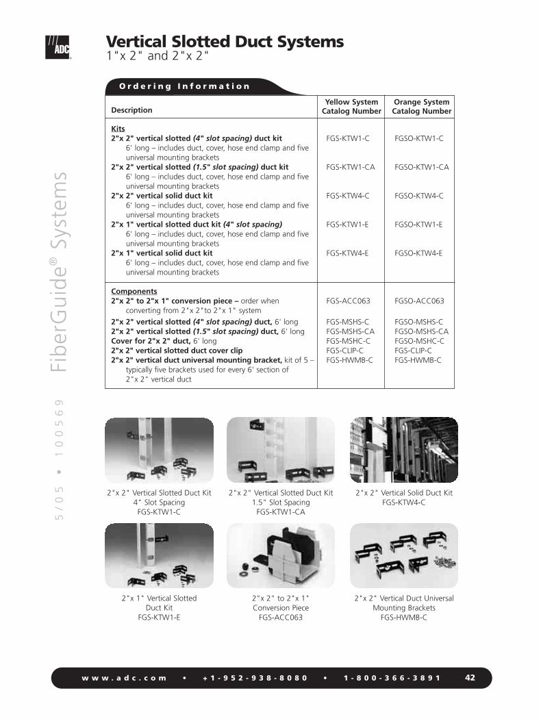
Kits2"x 2" vertical slotted (4" slot spacing) duct kit
6' long – includes duct, cover, hose end clamp and fiveuniversal mounting brackets
2"x 2" vertical slotted (1.5" slot spacing) duct kit6' long – includes duct, cover, hose end clamp and fiveuniversal mounting brackets
2"x 2" vertical solid duct kit6' long – includes duct, cover, hose end clamp and five universal mounting brackets
2"x 1" vertical slotted duct kit (4" slot spacing)6' long – includes duct, cover, hose end clamp and five universal mounting brackets
2"x 1" vertical solid duct kit6' long – includes duct, cover, hose end clamp and five universal mounting brackets
Components2"x 2" to 2"x 1" conversion piece – order when
converting from 2"x 2"to 2"x 1" system
2"x 2" vertical slotted (4" slot spacing) duct, 6' long2"x 2" vertical slotted (1.5" slot spacing) duct, 6' longCover for 2"x 2" duct, 6' long2"x 2" vertical slotted duct cover clip 2"x 2" vertical duct universal mounting bracket, kit of 5 –
typically five brackets used for every 6' section of 2"x 2" vertical duct
Orange SystemCatalog Number
FGSO-KTW1-C
FGSO-KTW1-CA
FGSO-KTW4-C
FGSO-KTW1-E
FGSO-KTW4-E
FGSO-ACC063
FGSO-MSHS-CFGSO-MSHS-CAFGSO-MSHC-CFGS-CLIP-CFGS-HWMB-C
2"x 2" Vertical Slotted Duct Kit 4" Slot SpacingFGS-KTW1-C
2"x 2" Vertical Solid Duct Kit FGS-KTW4-C
2"x 1" Vertical Slotted Duct Kit
FGS-KTW1-E
2"x 2" to 2"x 1"Conversion Piece
FGS-ACC063
Yellow SystemCatalog Number
FGS-KTW1-C
FGS-KTW1-CA
FGS-KTW4-C
FGS-KTW1-E
FGS-KTW4-E
FGS-ACC063
FGS-MSHS-CFGS-MSHS-CAFGS-MSHC-CFGS-CLIP-CFGS-HWMB-C
2"x 2" Vertical Duct UniversalMounting Brackets
FGS-HWMB-C
O r d e r i n g I n f o r m a t i o n

5/
05
•
1
00
56
9Fi
ber
Gu
ide®
Syst
ems
43w w w . a d c . c o m • + 1 - 9 5 2 - 9 3 8 - 8 0 8 0 • 1 - 8 0 0 - 3 6 6 - 3 8 9 1
Vertical Slotted Duct Systems2"x 4" and 4"x 4"
4"x 4" Vertical Slotted Duct Kit
FGS-KTW2-D
4"x 4" Vertical SlottedAdapter Junction Kit
FGS-MJWR-D
4"x 4" Vertical DuctMounting Bracket
FGS-HWMB-D
Description
Kits4"x 4" vertical slotted, (4" slot spacing) duct kit
6' long – includes duct, cover and three mounting brackets
2"x 4" vertical slotted, (1.5" slot spacing) duct kit6' long – includes duct, cover and three mounting brackets
4"x 4" vertical slotted adapter junction kit – used to join 4"x 4" vertical duct to standard 4x4 FiberGuide® profile
Components4"x 4" vertical slotted duct, 6' longCover for 2"x 4" and 4"x 4"vertical slotted duct, 6' long4"x 4" vertical slotted duct mounting bracket –
typically three brackets used for every 6' section of 4"x 4" vertical duct
2"x 4" vertical slotted duct mounting bracket – kit of 102"x 4" vertical slotted duct cap2"x 4" vertical slotted duct cover clip4"x 4" vertical slotted duct cover clip
Orange SystemCatalog Number
FGSO-KTW2-D
FGSO-KTW2-E
FGSO-MJWR-D
FGSO-MSHS-DFGSO-MSHC-DFGS-HWMB-D
FGS-HKWZ-EFGS-HMEC-EFGS-CLIP-EFGS-CLIP-D
Yellow SystemCatalog Number
FGS-KTW2-D
FGS-KTW2-E
FGS-MJWR-D
FGS-MSHS-DFGS-MSHC-DFGS-HWMB-D
FGS-HKW2-EFGS-HMEC-EFGS-CLIP-EFGS-CLIP-D
2"x 4" Vertical Slotted Duct Kit
FGS-KTW2-E
O r d e r i n g I n f o r m a t i o n

5/
05
•
1
00
56
9Fi
ber
Gu
ide®
Syst
ems
44w w w . a d c . c o m • + 1 - 9 5 2 - 9 3 8 - 8 0 8 0 • 1 - 8 0 0 - 3 6 6 - 3 8 9 1
2x2 System Support KitsFor Yellow and Orange Systems
Direct Support Kits
Description
2x2 ladder rack support kit – for use with 3.5" (maximum) ladder rack2x2 bay top support short L bracket kit 2x2 bay top support long L bracket kit 2x2 digital cableway support kit2x2 under floor support kit – can be secured to .62" to 1.2" round or square post
Catalog Number
FGS-HLR2-CFGS-BTBS-CFGS-BTBL-CFGS-HDCB-CFGS-HUFB-C
2x2 Ladder Rack Support KitShown Alone and Attached to
Ladder Rack: FGS-HLR2-C
2x2 Bay Top Support Short LBracket Kit: FGS-BTBS-C
2x2 Bay Top Support Long LBracket Kit: FGS-BTBL-C
2x2 Digital CablewaySupport Kit: FGS-HDCB-C
2x2 Under Floor Support KitShown Alone and Attached to.62 Round Pipe: FGS-HUFB-C
Note: Recommended spacing of direct support kits is every 2' to 3'.Custom brackets are available, please contact ADC.
O r d e r i n g I n f o r m a t i o n

5/
05
•
1
00
56
9Fi
ber
Gu
ide®
Syst
ems
45w w w . a d c . c o m • + 1 - 9 5 2 - 9 3 8 - 8 0 8 0 • 1 - 8 0 0 - 3 6 6 - 3 8 9 1
2x2 System Support KitsFor Yellow and Orange Systems
Aluminum Track Support KitFGS-HASK-C
2" New Threaded Rod BracketKit Shown Alone and Attached
to Aluminum Track SupportFGS-HTR2-XX
Description
Aluminum track support kit, 6' long, includes track connecting bar kit –aluminum track is self-supporting for spans up to 6'
2x2 new threaded rod bracket kit, 5/8" – used to support aluminum track kit
2x2 new threaded rod bracket kit, 1/2" – used to support aluminum track kit
2x2 existing thread rod bracket kit for up to two 2x2 FiberGuide® Systems
Track connecting bar kit – used to join two aluminum track kits; order only if extras are needed
2" new threaded rod bracket kit, 12 mm
Catalog Number
FGS-HASK-C
FGS-HTR2-5/8
FGS-HTR2-1/2
FGS-HTR2-2-5/8
FGS-HAEJ-C
FGS-HTR2-12MM
Note: Recommended spacing of track support kits is every 5' to 6'.Custom brackets are available, please contact ADC.
2" Existing Threaded RodBracket Kit
FGS-HTR2-2-5/8
O r d e r i n g I n f o r m a t i o n
Track Support Kits

5/
05
•
1
00
56
9Fi
ber
Gu
ide®
Syst
ems
46w w w . a d c . c o m • + 1 - 9 5 2 - 9 3 8 - 8 0 8 0 • 1 - 8 0 0 - 3 6 6 - 3 8 9 1
2x6, 4x4, 4x6 Systems Support KitsFor Yellow and Orange Systems
Description
Ladder rack cantilever support bracket kit
L bay support bracket kit
New threaded rod bracket kit (XX = size: 1/2", 5/8", 12 mm, 14 mm, 16 mm, 18 mm)
Existing threaded rod bracket kit (XX = size: 1/2", 5/8", 12 mm, 14 mm, 16 mm)
Modified new threaded rod bracket kit, 5/8"
Top support low-profile C-bracket kit (XX = size: 1/2", 5/8", 12 mm, 14 mm, 16 mm)
Top support C-bracket kit (XX = size: 1/2", 5/8", 12 mm, 14 mm, 16 mm)
Modified existing threaded rod bracket kit, 5/8"
Center support bracket kit (XX = size: 1/2", 5/8", 12 mm, 14 mm, 16 mm, 20 mm)
Digital cableway bracket kit, 12"
Digital cableway bracket kit, 15"
Ladder rack center support bracket kit
OMX frame center support bracket kit, 16 mm
Under floor support bracket kit
Catalog Number
FGS-HDLB-4
FGS-HLBK
FGS-HNTR-XX
FGS-HETR-XX
FGS-HNTR-5/8-A
FGS-HNTS-XX-LP
FGS-HNTS-XX
FGS-HETR-5/8-A
FGS-HTUB-XX
FGS-HCBL-12
FGS-HCBL-15
FGS-HNLR-AB
FGS-HOMX-16MM
FGS-HUFB-A
New Threaded Rod BracketKit Shown Alone and
Attached to Threaded RodFGS-HNTR-XX
Existing Threaded Rod BracketKit Shown Alone and
Attached to Threaded RodFGS-HETR-XX
Custom brackets are available, please contact ADC.
Top Support C-BracketFGS-HNTS-XX
Ladder Rack Cantilever Support Bracket Kit
FGS-HDLB-4
L Bay Support BracketShown Alone and
Attached to 4x4 FiberGuideFGS-HLBK
Modified New Threaded RodBracket Kit Shown Alone and
Attached to Threaded RodFGS-HNTR-5/8-A
Top Support C-Bracket Low Profile
FGS-HNTS-XX-LP
Modified Existing Threaded RodBracket Kit Shown Alone and
Attached to Threaded RodFGS-HETR-5/8-A
Center Support BracketFGS-HTUB-XX
O r d e r i n g I n f o r m a t i o n

5/
05
•
1
00
56
9Fi
ber
Gu
ide®
Syst
ems
47w w w . a d c . c o m • + 1 - 9 5 2 - 9 3 8 - 8 0 8 0 • 1 - 8 0 0 - 3 6 6 - 3 8 9 1
4x12 System Support KitsFor Yellow and Orange Systems
Description
New ladder rack center support bracket kitExisting ladder rack center support bracket kit
(XX = size: 1/2", 5/8", 12 mm, 14 mm, 16 mm)Trapeze bracket kit
(XX = size: 1/2", 5/8", 12 mm, 14 mm, 16 mm)Center support threaded rod bracket kit
(XX = size: 1/2", 5/8", 12 mm, 14 mm, 16 mm, 20 mm)Top support low-profile threaded rod bracket kit
(XX = size: 1/2", 5/8", 12 mm, 14 mm, 16 mm)Top support threaded rod bracket kit
(XX = size: 1/2", 5/8", 12 mm, 14 mm, 16 mm)New threaded rod bracket kit
(XX = size: 5/8", 14 mm, 16 mm, 18 mm)Existing threaded rod bracket kit
(XX = size: 5/8", 14 mm, 16 mm)
Catalog Number
FGS-HNLR-FFGS-HETP-F-XX
FGS-HNTP-F-XX
FGS-HTUB-F-XX
FGS-HNTS-F-XX-LP
FGS-HNTS-F-XX
FGS-HNTR-F-XX
FGS-HETR-F-XX
Existing Ladder Rack CenterSupport Bracket Kit
FGS-HETP-F-XX
Trapeze Bracket KitFGS-HNTP-F-XX
Top Support Threaded RodBracket Kit
FGS-HNTS-F-XX
New Threaded Rod Bracket Kit FGS-HNTR-F-XX
Existing Threaded Rod Bracket Kit
FGS-HETR-F-XX
Top Support Low-Profile KitShown Alone and Attached to
Threaded RodFGS-HNTS-F-XX-LP
Center Support Bracket KitShown Alone and Attached to
Threaded RodFGS-HTUB-F-XX
Custom brackets are available, please contact ADC.
O r d e r i n g I n f o r m a t i o n

5/
05
•
1
00
56
9Fi
ber
Gu
ide®
Syst
ems
48w w w . a d c . c o m • + 1 - 9 5 2 - 9 3 8 - 8 0 8 0 • 1 - 8 0 0 - 3 6 6 - 3 8 9 1 48
Accessories
Trough cover clip kit
2" outer diameter slotted flex tube(X = length: 5, 10, 15, 20, 25, 50, 75, 100, 125,150, 200, 250)
1" outer diameter slotted flex tube(X = length: 5, 10, 15, 20, 25, 50, 75, 100, 125,150, 200, 250)
7/8" outer diameter slotted flex tube(X = length: 5, 10, 15, 20, 25, 50, 75, 100, 125,150, 200, 250)
2" outer diameter solid flex tube(X = length: 5, 10, 15, 20, 25, 50, 75, 100, 125,150, 200, 250)
Single hinges for 4x4 and 4x6 covers
Vertical spring hinges, kit of 3
Retainer rings, kit of 10 – used to retain fibers in 2" flex tube
Flex tube clamp, kit of 10 – used to secure 2" flex tube to 2" vertical ducts
Storage spools for dark fiber jumpers – kit of 2
Mitre box with saw – used to cut 2x2, 4x4, 4x6, and 4x12 FiberGuide® straight sections to size
Mitre box with saw – used to cut 2x2, 4x4, and 4x6 FiberGuide straight sections to size
IFC tie downfor 4x4 systemfor 4x6 systemfor 4x12 system
Quick knobs with T-bolt
Reverse junction adapter kit for 4x4, 4x6, and4x12 systems – used to connect two parts rotated 180°
Retrofit fin, kit of 10
Description
O r d e r i n g I n f o r m a t i o n
Yellow SystemCatalog Number
Orange SystemCatalog Number
FGS-KT09
FGS-MIDY-XF
FGS-MLDY-XF
FGS-MFTY-XF
FGS-MISY-XF
FGS-HHGK
FGS-HVHG
FGS-HFRR-10
FGS-HHEC-10
FGS-MSTOR-A/B/F
FGS-MKIT-ABF
FGS-MKIT
FGS-HIFC-AFGS-HIFC-BFGS-HIFC-F
FGS-KQKB
FGS-HRJA-A/B/F
FGS-MFIN-10
FGS-KT09
FGSO-MIDY-XF
FGSO-MLDY-XF
FGSO-MFTY-XF
FGSO-MISY-XF
FGS-HHGK
FGS-HVHG
FGS-HFRR-10
FGS-HHEC-10
FGS-MSTOR-A/B/F
FGS-MKIT-ABF
FGS-MKIT
FGS-HIFC-AFGS-HIFC-BFGS-HIFC-F
FGS-KQKB
FGS-HRJA-A/B/F
FGS-MFIN-10

Storage SpoolsFGS-MSTOR-A/B/F
5/
05
•
1
00
56
9Fi
ber
Gu
ide®
Syst
ems
49w w w . a d c . c o m • + 1 - 9 5 2 - 9 3 8 - 8 0 8 0 • 1 - 8 0 0 - 3 6 6 - 3 8 9 1
Accessories
Single Hinges for 4" and 6" Covers
FGS-HHGK
Retainer RingsFGS-HFRR-10
2" Outer Diameter Slotted Flex Tube
FGS-MIDY
7/8" Outer Diameter Slotted Flex Tube
FGS-MFTY
Mitre Box and SawFGS-MKIT-ABF
Flex Tube ClampFGS-HHEC-10
Retrofit Fin – Set of 10FGS-MFIN-10
Quick Knobs - Kit of 10FGS-KQKB
FGS-MSTOR-A/B/F(Shown Installed)

5/
05
•
1
00
56
9Fi
ber
Gu
ide®
Syst
ems
50w w w . a d c . c o m • + 1 - 9 5 2 - 9 3 8 - 8 0 8 0 • 1 - 8 0 0 - 3 6 6 - 3 8 9 1
Support Kit AccessoriesFor Yellow and Orange Systems
Description
Threaded rod 5/8" - 11 x 12"5/8" - 11 x 30"5/8" - 11 x 72"1/2" - 13 x 12"1/2" - 13 x 30"1/2" - 13 x 72"
Threaded rod; (XX = size: 12 mm, 14 mm, 16 mm)(NN = length: 30 cm, 75 cm, 180 cm)
Auxiliary framing kit2" x 9/16" x 3/16" for 5/8" rod2" x 9/16" x 3/16" for 1/2" rod
Adjustable angle support brackets with 5/8" threaded rod11 x 36" rod11 x 48" rod
Adjustable angle support brackets with 1/2" threaded rod 13 x 36" rod13 x 48" rod
Ladder rack bracket kit for radiused ladder racking
Ladder rack bracket kit, 1/2", 5/8", 12 mm, 14 mm, 16 mm
Unistrut nut kit, 5/8"
Frame mounting hardware kit (XX = size: 1/2", 5/8", 12 mm, 14 mm, 16 mm)
Threaded RodFGS-HTHR
Auxiliary Framing KitFGS-HFCK
Adjustable Angle Support Brackets
FGS-HASB
Catalog Number
FGS-HTHR-5/8-12FGS-HTHR-5/8-30FGS-HTHR-5/8-72FGS-HTHR-1/2-12FGS-HTHR-1/2-30FGS-HTHR-1/2-72
FGS-HTHR-XX-NN
FGS-HFCK-5/8FGS-HFCK-1/2
FGS-HASB-5/8-36FGS-HASB-5/8-48
FGS-HASB-1/2-36FGS-HASB-1/2-48
FGS-HLDR-A
FGS-HLDR-XX
FGS-HDGR
FGS-HKFM-XX
Ladder Rack Bracket KitShown Alone and
Attached to Ladder RackFGS-HLDR
Unistrut Nut KitFGS-HDGR
O r d e r i n g I n f o r m a t i o n

5/
05
•
1
00
56
9Fi
ber
Gu
ide®
Syst
ems
51w w w . a d c . c o m • + 1 - 9 5 2 - 9 3 8 - 8 0 8 0 • 1 - 8 0 0 - 3 6 6 - 3 8 9 1
2.0"(5.08 cm)
2x2 System Parts
2x2 Horizontal TFGS-MHTA-C
2x2 90° Horizontal ElbowFGS-MH9A-C
2x2 Horizontal CrossFGS-MHXP-C
8.03"(20.39 cm)
2.22"(5.64 cm)5.13"
(13.03 cm) Top
2.08"(5.28 cm)
2.0" (5.1 cm)
End
Top
Front2.06"
(5.23 cm)
10.1"(25.65 cm)
2.0"(5.08 cm)
7.97"(20.24 cm)
2.0"(5.08 cm)
2.0"(5.08 cm)
Front
2x2 90° Horizontal ElbowFGS-MH9A-C-45/2
End 2.08"(5.28 cm)
2.0"(5.1 cm)
Top
2.22"(5.64 cm)
6.75"(17.1 cm)
6.75"(17.1 cm)
2.00"(5.08 cm)
2.08"(5.28 cm)
4.59"(11.66 cm)
2x2 45° Horizontal ElbowFGS-MH4A-C
2x2 45° Up ElbowFGS-MU4A-C
4.59"(11.66 cm)
Side
2.22"(5.64 cm)
3.42"(8.68 cm)
2.0"(5.1 cm)
End
2.08"(5.28 cm)

5/
05
•
1
00
56
9Fi
ber
Gu
ide®
Syst
ems
52w w w . a d c . c o m • + 1 - 9 5 2 - 9 3 8 - 8 0 8 0 • 1 - 8 0 0 - 3 6 6 - 3 8 9 1
2x2 System Parts
2x2 to 4x4 Straight AdapterFGS-MDSA-AC
2x2 45° Down ElbowFGS-MD4A-C
2x2 Horizontal Straight Section FGS-MSHA-C
2x2 90º Down ElbowFGS-MD9A-C
2x2 90º Up Elbow FGS-MU9A-C
2.22"(5.64 cm)
2.0"(5.1 cm)
End
4.54"(11.53 cm)
Side
2.08"(5.28 cm)
3.32"(8.43 cm)
2.0"(5.1 cm)
0.5" (1.3 cm)0.5" (1.3 cm)
5" (1.3 cm)
4.0" (10.2 cm)72" (182.9 cm)
SideEnd
Bottom
2.0" (5.1 cm)
2.0" (5.1 cm)
Front
4.42"(11.2 cm)
4.0"(10.16 cm)
2.0"(5.08 cm)
5.67"(14.4 cm)
6.56"(16.7 cm)
Top
2x2 Extended DownspoutFGS-KDH2-C
5.0"(12.7 cm)
2.32"(5.89 cm)
5.43"(13.89 cm)
SideEnd2.0"
(5.1 cm)
2x2 Standard DownspoutFGS-MSDS-C
12.96"(32.92 cm)
Top
3.5"(9.04 cm)
2.08"(5.28 cm)
5.02"(12.75 cm)
Front
2.0"(5.08 cm)
2.0"(5.08 cm)
1.85"(4.7 cm)
1.85"(4.7 cm)
2.08"(5.28 cm)
4.91"(12.47 cm)
1.85"(4.7 cm)
1.85"(4.7 cm)
2.0"(5.08 cm)
2.0"(5.08 cm)
2.08"(5.28 cm)
5.07"(12.88 cm)

5/
05
•
1
00
56
9Fi
ber
Gu
ide®
Syst
ems
53w w w . a d c . c o m • + 1 - 9 5 2 - 9 3 8 - 8 0 8 0 • 1 - 8 0 0 - 3 6 6 - 3 8 9 1
14.0"(35.56 cm)
7.67"(19.48 c
2.0"(5.08 cm)
2x6 System Parts
1.125"(2.86 cm)
14.0"(35.56 cm)
2x6 to 2x2 DownspoutFGS-MDSP-G
13.5"(34.29 cm)
6.0"(15.24 cm)
1.75"(4.45 cm)
10.6"(26.92 cm)
2x6 Horizontal TFGS-MHRT-G
1.75"(4.45 cm)
6.0"(15.24 cm)
10.6"(26.92 cm)
10.6"(26.92 cm)
1.4"(3.56 cm)
1.4"(3.56 cm)
2x6 90º Horizontal ElbowFGS-MH9E-G
6.0"(15.24 cm)
1.75"(4.45 cm)
5.7"(14.48 cm)
1.4"(3.56 cm)
1.4"(3.56 cm)
7.7"(19.56 cm)
2x6 90º Down ElbowFGS-MD9E-G
1.4"(3.56 cm)
45°
9.1"(23.11 cm)
8.9"(22.61 cm)
6.0"(15.24 cm)
1.75"(4.45 cm)
1
7.7"(19.56 cm)
2x6 45º Horizontal ElbowFGS-MH4E-G
6.0"(15.24 cm)
1.75"(4.45 cm)
7.7"(19.56 cm)
2x6 45º Up ElbowFGS-MU4E-G
13.5"
(34.29 cm)
13.5"(34.29 cm)
6.0"(15.24 cm)
1.75"(4.45 cm)
2x6 Horizontal CrossFGS-MHXP-G
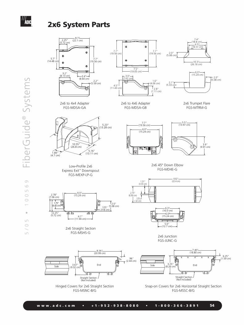
5/
05
•
1
00
56
9Fi
ber
Gu
ide®
Syst
ems
54w w w . a d c . c o m • + 1 - 9 5 2 - 9 3 8 - 8 0 8 0 • 1 - 8 0 0 - 3 6 6 - 3 8 9 1
8.82"(22.4 cm)1.31"
(3.33 cm)
.125(.32 cm)
2.75"(6.99 cm)
2x6 System Parts
5.5"(13.97 cm)
6.0"(15.24 cm)
3.9"(9.91 cm)
7.7"(19.56 cm)
2x6 45º Down ElbowFGS-MD4E-G
2.8"(7.11 cm)
4.5"(11.43 cm)
7.5"(19.05 cm)
1.6"(4.06 cm)
3.0"(7.62 cm)
7.7"(19.56 cm)
7.7"(19.56 cm)
5.16"(13.11 cm)
10.55"(26.8 cm)
1.85"(4.7 cm)
5.23"(13.28 cm)
Low-Profile 2x6 Express Exit™ Downspout
FGS-MEXP-LP-G
2.25"(5.72 cm)
2.78"(7.06 cm)
6.0"(15.24 cm)
1.75"(4.45 cm)
.125"(.318 cm)
2.0"(5.08 cm)
4.7"(11.94 cm)
6.25"(1.59 cm)
7.40"(18.80 cm)
3.25"(8.26 cm) EndSide
Straight Section(Not Included)
2x6 Straight SectionFGS-MSHS-G
6.0"(15.24 cm)
6.3"(16.0 cm)
5.0"(12.7 cm)
2x6 JunctionFGS-JUNC-G
7.4"(18.8 cm)
2.0"(5.08 cm)
6.0"(15.24 cm)
2.1"(5.33 cm)
10.3"(26.16 cm)
2.0"(5.08 cm)
6.5"(16.51 cm)
2x6 Trumpet FlareFGS-MTRM-G
3.2"(8.13 cm)
2.2"(5.59 cm)
8.7"(22.1 cm)
7.7"(19.56 cm)
5.7"(14.48 cm)
3.4"(8.64 cm)
2.25"(5.72 cm)
2x6 to 4x4 AdapterFGS-MDSA-GA
2x6 to 4x6 AdapterFGS-MDSA-GB
Hinged Covers for 2x6 Straight SectionFGS-MSNC-B/G
Snap-on Covers for 2x6 Horizontal Straight SectionFGS-MSSC-B/G
.96"(2.44 cm)
8.26"(20.99 cm)
3.67"(9.32 cm)
EndSide
Straight Section(Not Included)

5/
05
•
1
00
56
9Fi
ber
Gu
ide®
Syst
ems
55w w w . a d c . c o m • + 1 - 9 5 2 - 9 3 8 - 8 0 8 0 • 1 - 8 0 0 - 3 6 6 - 3 8 9 1
4x4 System Parts
4x4 45° Horizontal ElbowFGS-MH4E-A
4x4 90° Up ElbowFGS-MU9E-A
4x4 90° Down ElbowFGS-MD9E-A
Top8.79"
(22.3 cm)
7.65"(19.4 cm)
4.0" (10.2 cm)
End
4.42" (11.2 cm)
End
10.22"(26.0 cm)
6.48"(16.5 cm)
10.22"(26.0 cm)4.73"
(12.0 cm)
8.60"(21.8 cm)
8.60"(21.8 cm)
Side
Junction Detail(Not Included)
R 2.0"(5.08 cm)
Side 8.19"(20.8 cm)
8.19"(20.8 cm)
4.0"(10.2 cm)
End
5.67"(14.4 cm)
4.42"(11.2 cm)
4x4 Horizontal TFGS-MHRT-A
Top
4.0"(10.2 cm)
12.99"(33.0 cm)
9.33"(23.7 cm)
Front
4.42"(11.2 cm)
4x4 Horizontal CrossFGS-MHXP-A
4x4 90° Horizontal ElbowFGS-MH9E-A
Top
4.0" (10.2 cm)
9.33" (23.7 cm)
9.33"(23.7 cm)
End
4.42" (11.2 cm)
4.0"(10.2 cm)
12.99"(33.0 cm)
12.99"(33.0 cm)
4.42"(11.2 cm)Front
Top

5/
05
•
1
00
56
9Fi
ber
Gu
ide®
Syst
ems
56w w w . a d c . c o m • + 1 - 9 5 2 - 9 3 8 - 8 0 8 0 • 1 - 8 0 0 - 3 6 6 - 3 8 9 1
4x4 System Parts
4x4 45° Up ElbowFGS-MU4E-A
R 2.0"(5.08 cm)
Side8.0"
(20.3 cm)
4.9" (12.4 cm)
6.55" (16.6 cm)
8.27" (21.0 cm)
Top
9.9"(25.1 cm)
6.4"(16.3 cm)
Junction Detail(Not Included)
4x4 45° Down ElbowFGS-MD4E-A
Side
45°
7.98"(20.27 cm)
4.85"(12.3 cm)
4.42"(11.2 cm)
6.43" (16.3 cm)
5.67"(14.4 cm)
4.0" (10.2 cm)
End
4x4 to 4x6 Straight AdapterFGS-MDSA-AB
Front4.42" (11.2 cm)
4.0" (10.16 cm)
7.67"(19.5 cm)
5.67"(14.4 cm)
7.31"(18.6 cm)
Top
4x4 Cut-in TFGS-MHIS-A
4x4 Expandable Straight SectionFGS-MVAR-A
14.0"(35.56 cm)
22.0"(55.88 cm)
Retracted Straight Section
Expanded Straight Section
13.59"(34.52 cm) 10.0"
(25.4 cm)
12.99"(32.99 cm)
4.0"(10.16 cm)
12.0"(30.48 cm)
6.25"(15.88 cm)
4x4 DownspoutFGS-MDSP-A
Top
4.0 "(10.2 cm)
1.75"(4.4 cm)
5.67"(14.4 cm)
12.96" (32.9 cm) Front
4.42"(11.2 cm)
6.31"(16.0 cm)5.67"
(14.4 cm)
4x4 Extended DownspoutFGS-MDSP-EX-A
13.0"(33.02 cm)
11.0"(27.94 cm)
4.0"(10.16 cm)
8.31"(21.11 cm)
5.67"(14.4 cm)
5.25"(13.34 cm)
5.40"(13.72 cm)
.625"(Not Included)
EndSide
Snap-On Cover for 4" Straight SectionFGS-MSSC-A

5/
05
•
1
00
56
9Fi
ber
Gu
ide®
Syst
ems
57w w w . a d c . c o m • + 1 - 9 5 2 - 9 3 8 - 8 0 8 0 • 1 - 8 0 0 - 3 6 6 - 3 8 9 1
4x4 System Parts
4" Square to 2" Round Adapter with Flex Tube
FGS-ASRI
4.55"(11.6 cm)
4.62"(11.7 cm)
5.67"(14.4 cm)
X
Dimension X5' (1.52 m)10' (3.05 m)15' (3.57 m)
4x4/4x6 Downspout InsertFGS-HDSI-AB
8.40"(21.34 cm)
4.04"(10.26 cm)
4.09"(10.39 cm)
4x4 Horizontal Straight SectionFGS-MSHS-A
Hinged Cover for 4" Horizontal Straight SectionFGS-MSNC-A
4x4 Trumpet Flare KitFGS-MTRM-A
Side
72.0" (182.9 cm)
4.55" (11.6 cm)
End
4.0"(10.2 cm)
5.67"(14.4 cm)
4.0"(10.2 cm)
5.42"(13.77 cm)
6.26"(15.91 cm)
.96"(2.44 cm)
EndSide
Straight Section(Not Included)
CLO
SE
OPEN
2.0" (5.1 cm)
R 2.0" (5.1 cm)
Top
8.3" (21.1 cm)
3.0"(7.6 cm)
End6.25" (15.9 cm)
6.8"(17.3 cm)
4.25"(10.8 cm)
4x4 Snap-Fit Junction AssemblyFGS-MFAW-A
7.04
5.63
4.0

5/
05
•
1
00
56
9Fi
ber
Gu
ide®
Syst
ems
58w w w . a d c . c o m • + 1 - 9 5 2 - 9 3 8 - 8 0 8 0 • 1 - 8 0 0 - 3 6 6 - 3 8 9 1
4x6 System Parts
4x6 45° Up ElbowFGS-MU4E-B
4x6 45° Down ElbowFGS-MD4E-B
7.67"(19.5 cm)
6.42" (16.3 cm)
6.00" (15.2 cm)
End
45°
Side
4.42"(11.2 cm)
7.98" (20.3 cm)
4.85"(12.3 cm)
4x6 90° Down ElbowFGS-MD9E-B
4x6 Horizontal TFGS-MHRT-B
4x6 Horizontal CrossFGS-MHXP-B
4x6 90° Horizontal ElbowFGS-MH9E-B
Top
14.99" (38.1 cm)
11.33"(28.8 cm)
Front
4.42"(11.2 cm)
6.0" (15.2 cm)
14.99"(38.1 cm)
14.99"(38.1 cm)
4.42"(11.2 cm)
Front
Top
6.0"(15.2 cm)
Top
11.33"(28.8 cm)
11.33"(28.8 cm)
End
4.42"(11.2 cm)
6.0"(15.2 cm)
8.0"(20.3 cm)
4.9" (12.4 cm)
6.55"(16.6 cm)
8.27"(21.0 cm)
9.9" (25.1 cm)
8.4"(21.3 cm)
Junction Detail(Not Included)
Top
Side
R 2.0"(5.1 cm)
Side
4.42"(11.2 cm)
8.19"(20.8 cm)
8.19"(20.8 cm)
6.0"(15.2 cm)
End
7.67"(19.5 cm)
4x6 90º Up ElbowFGS-MU9E-B
8.6'
4.25"(10.8 cm)
4.25"(10.8 cm)
4.5"(11.43 cm)
7.7"(19.56 cm)
7.2"(18.29 cm)3.4"
(8.64 cm) .50"(1.27 cm)
4x6 45° Horizontal ElbowFGS-MH4E-B
10.20"(25.9 cm)
9.65"(24.5 cm)
End
Top
4.42"(11.2 cm)
6.0"(15.2 cm)

5/
05
•
1
00
56
9Fi
ber
Gu
ide®
Syst
ems
59w w w . a d c . c o m • + 1 - 9 5 2 - 9 3 8 - 8 0 8 0 • 1 - 8 0 0 - 3 6 6 - 3 8 9 1
4x6 System Parts
4x6 DownspoutFGS-MDSP-B
Top
4.0"(10.2 cm)
1.75" (4.4 cm)
7.67"(19.5 cm)
12.96" (32.9 cm)
Front4.42"
(11.2 cm)
6.31"(16.0 cm)
5.67"(14.4 cm)
4x6 Expandable Straight SectionFGS-MVAR-B
4x6 Cut-in TFGS-MHIS-B
14.0"(35.56 cm)
22.0"(55.88 cm)
Retracted Straight Section
Expanded Straight Section
15.0"(38.1 cm)
6.25"(15.88 cm)
6.0"(15.24 cm)
14.0"(35.56 cm)
12.0"(30.48 cm)
15.59"(39.6 cm)
4x6 Extended DownspoutFGS-MDSP-EX-B
6" Trumpet FlareFGS-MTRM-B
CLO
SE
OPEN
2.0"(5.1 cm)
R 2.0"(5.1 cm)
Top10.35 "
(26.29 cm)3.0"
(7.6 cm)
End6.25"(15.9 cm)
6" Straight SectionFGS-MSHS-B
Snap-On Cover for 6" Straight SectionFGS-MSSC-B/G
Side
72.0"(182.9 cm)
4.55"(11.6 cm)
End
6.0"(15.2 cm)
7.67" (19.5 cm)
4.0"(10.2 cm) 5.25"
(13.34 cm)
7.40"(18.80 cm)
.625"(1.59 cm)
EndSide
Straight Section(Not Included)
6" Snap-Fit Junction AssemblyFGS-MFAW-B
Hinged Cover for 6" Straight SectionFGS-MSNC-B/G
6" Slack Storage Straight SectionFGS-MSHS-STOR-B
8.8"(22.35 cm)
4.25"(10.8 cm)
12.0"(30.48 cm)
3.5" (8.89 cm)diameter
1.25"(3.18 cm)
12.96"(32.92 cm)
13.0"(33.02 cm)
8.31"(21.11 cm)
4.0"(10.16 cm)
5.67"(14.4 cm)
9.04
5.63
6.0
5.42"13.77 cm)
8.26"(20.99 cm)
.96"(2.44 cm
EndSide
Straight Section(Not Included)

5/
05
•
1
00
56
9Fi
ber
Gu
ide®
Syst
ems
60w w w . a d c . c o m • + 1 - 9 5 2 - 9 3 8 - 8 0 8 0 • 1 - 8 0 0 - 3 6 6 - 3 8 9 1
4x12 System Parts
4x12 45° Up ElbowFGS-MU4E-F
4x12 90° Down ElbowFGS-MD9E-F
4x12 45° Horizontal ElbowFGS-MH4E-F
4x12 45° Down ElbowFGS-MD4E-F
4x12 Horizontal TFGS-MHRT-F
4x12 Horizontal CrossFGS-MHXP-F
4x12 90° Horizontal ElbowFGS-MH9E-F
17.33"
20.99"
4.42" 13.67"
13.62"
(53.31 cm)
(34.72 cm)
(44.02 cm)
Top
(34.72 cm)(11.23 cm)
12"(30.48 cm)
20.99"
4.42"
20.99"(53.31 cm)
(53.31 cm)
13.67"(34.72 cm)
(11.23 cm)
12"(30.48 cm)
Top
4.42"
17.33"
17.33"
12"(30.48 cm) (11.23 cm)
(44.02 cm)
Top
(44.02 cm)
13.67"(34.72 cm)
13.67"8.19"
4.42"
(34.72 cm)
12"(30.48 cm)
Side
(20.80 cm)
(11.23 cm)
8.19"(20.80 cm)
4.42"
13.67"
14.44"(11.23 cm)
12"(30.48 cm)
(34.72 cm)15.65"
(39.75 cm)Top
13.67"(34.72 cm)
12"(30.48 cm)
13.4"(34.04 cm)
.98"(2.49 cm)
4.42"13.67"(34.72 cm)
Side
(11.23 cm)
12"(30.48 cm)
6.43"(16.33 cm)
4x12 Horizontal T with (one) 6" ExitFGS-MHRT-F/B
4.42"
14.99"
13.67"
7.67"
(38.07 cm)
(34.72 cm)
(19.48 cm)
Top
17.33"(44.01 cm)
12"(30.48 cm)
(11.23 cm)6"
(15.24 cm)

5/
05
•
1
00
56
9Fi
ber
Gu
ide®
Syst
ems
61w w w . a d c . c o m • + 1 - 9 5 2 - 9 3 8 - 8 0 8 0 • 1 - 8 0 0 - 3 6 6 - 3 8 9 1
20.0"(50.8 cm)
21.0"(53.34 cm)
21.59"(54.84 cm)18.0"
(45.72 cm)
6.25"(15.88 cm)
12.0"(30.48 cm)
4x12 System Parts
4x12 Trumpet KitFGS-MTRM-F
4x12 End CapFGS-HMEC-F
4x12 Horizontal Cross with (two) 6" ExitsFGS-MHXP-F/B
4x12 to 4x6 Dual AdapterFGS-MDSA-F2B
4x12 to 4x6 AdapterFGS-MDSA-FB
4.42"
14.99"
20.99"Top
(38.07 cm)
13.67"(34.72 cm)
(53.31 cm)
7.67"(19.48 cm)
12"(30.48 cm)
6"(15.24 cm)
(11.23 cm)
4.42"
18.29"
7.67"
10.99"
Top
(19.48 cm)
(46.46 cm)
(27.91 cm)
(11.23 cm)
13.67"(34.72 cm)
12"(30.48 cm)
6"(15.24 cm)
13.67"
7.67"
12"(30.48 cm)
10"(25.40 cm)
(19.48 cm)
(34.72 cm)
6"(15.24 cm)
4.42"(11.23 cm)
Top
2.50"
16.31"
12.33"3.50"
2.00"2.50"
(31.32 cm)
(6.35 cm)
(6.35 cm)
(41.43 cm)
(8.89 cm)(5.08 cm)
13.51"
4.44"
(34.32 cm)
(11.28 cm)
14.0"(35.56 cm)
22.0"(55.88 cm)
Retracted Straight Section
Expanded Straight Section
4x12 Expandable Straight SectionFGS-MVAR-F
4x12 Cut-in TFGS-MHIS-F
4x12 Exit DownspoutFGS-MDSP-F
(38.1 cm)
(34.72 cm)
4.42"
(15.24 cm)
15.00"
6"
13.67"
12"(30.48 cm)
8.312"(21.11 cm)
(11.23 cm)Top

5/
05
•
1
00
56
9Fi
ber
Gu
ide®
Syst
ems
62w w w . a d c . c o m • + 1 - 9 5 2 - 9 3 8 - 8 0 8 0 • 1 - 8 0 0 - 3 6 6 - 3 8 9 1
4x12 System Parts
4x12 Snap-Fit JunctionFGS-MFAW-F
21.0"(53.34 cm)
10.0"(25.4 cm)
11.0"(27.94 cm)
5.0"(12.7 cm)2.9"
(7.37 cm)
16.6"(42.16 cm)
17.3"(43.94 cm)5.0"
(12.7 cm)
4x12 Downspout with Rear TFGS-MDRT-F
19.3"(49.02 cm)
10.5"(26.67 cm)
12.5"(31.75 cm)
8.0"(20.32 cm)
6.3"(16.0 cm)
.16"(.41 cm)
4x12 T with Recessed Dividing SpoolFGS-ISLAND3-F
17.3"(43.94 cm)
10.5"(26.67 cm)
4.0"(10.16 cm)
6.8"(17.27 cm)
4x12 Island TFGS-ISLAND-F
4.0"(10.16 cm)
10.7"(27.18 cm)
11.0"(27.94 cm)
5.7"(14.48 cm)
3.7"(9.4 cm)
1.5"(3.81 cm)
3.5"(8.89 cm)
4x12 Straight SectionFGS-MSHS-F
4x12 Slack Storage Straight SectionFGS-MSHS-STOR-F
12.0"(30.48 cm) 3.5" (8.89 cm)
diameter 4.25"(10.8 cm)
4.25”
12.0”
5.22”
15.04”
Hinged Cover for 12 Horizontal Straight Secion FGS-MSNC-F
.96"(2.44 cm)
14.43"(36.65 cm)
3.67"(9.32 cm)
EndSide
Straight Section(Not Included)

5/
05
•
1
00
56
9Fi
ber
Gu
ide®
Syst
ems
63w w w . a d c . c o m • + 1 - 9 5 2 - 9 3 8 - 8 0 8 0 • 1 - 8 0 0 - 3 6 6 - 3 8 9 1
Express Exit Family
2 Inch Express Exit(Shown Attached to 4x6 Straight Section)
FGS-MEXP-A/B/F
3.75"(9.53 cm)
2.0"(5.08 cm) Express Exit
4.91"(12.47 cm)
5.8"(14.73 cm)
10.0"(25.4 cm)
Bracket, Express Exit
Low Profile Express Exit(Shown Attached to 4x4 Straight Section)
FGS-MEXP-LP-A/B/F
1.99"(5.05 cm)
Low Profile Express Exit
5.2"(13.21 cm)
5.1"(12.95 cm)
10.25"(26.04 cm)
4 Inch Express Exit(Shown Attached to 4x4 Straight Section)
FGS-MEXP-E-A/B/F
16.0"(40.64 cm)
4.07"(10.34 cm)
7.89"(20.04 cm)
7.73"(19.63 cm)
Express Exit 2x4
Bracket,Express Exit 2x4

5/
05
•
1
00
56
9Fi
ber
Gu
ide®
Syst
ems
64w w w . a d c . c o m • + 1 - 9 5 2 - 9 3 8 - 8 0 8 0 • 1 - 8 0 0 - 3 6 6 - 3 8 9 1
2x2 System Support Kits
2" Digital Cable Way Support Kit
FGS-HDCB-C
2" Ladder Rack Support Kit (Shown Alone and Attached to Ladder Rack)
FGS-HLR2-C
2" Bay Top Support Short L Bracket Kit
FGS-BTBS-C, FGS-BTBL-C
2.68" (6.81 cm)
Top
3.31" (8.41 cm)
2.26"(5.74 cm)
2.01"(5.11 cm)
End
Existing Ladder Rack
SupportBracket
.25"(.64 cm)
Straight Section (Not Included)
Support Bracket
3.0" (7.62 cm)
5.34 or 15.45"(13.6 or 39.2 cm)
3.64"(9.2 cm)
1.75"(4.4 cm)
End
Top
1.500"(3.81 cm)
Top
Side
Support BracketStraight Section (Not Included)
DigitalCableway
(Not Included)9.075 to 10.075"
(23.05 to 25.59 cm)
4.540"(11.53 cm)
2" Under Floor Support Kit (Shown Attached to .62x2 Round Pipe)
FGS-HUFB-C
2.99"(7.59 cm)
Side End
Straight Section(Not Included)
3.03"(7.69 cm)
Support Bracket
Post
2" New Threaded Rod Bracket Kit (Shown Attached to Aluminum Track Support)
FGS-HTR2
Support Bracket
2.36"(5.99 cm)
2.89"(7.34 cm)
End
Threaded Rod (Not Included)
Straight Section(Not Included)
Aluminum Extrusion (Not Included)
Side
Aluminum Track Support KitFGS-HASK-C
Cap Screw
Lock Washer
Cap Screw
Lock Washer
Connector Bar
Connector Bar
AluminumExtrusion
End-to-End Assembly Method
AluminumExtrusion

5/
05
•
1
00
56
9Fi
ber
Gu
ide®
Syst
ems
65w w w . a d c . c o m • + 1 - 9 5 2 - 9 3 8 - 8 0 8 0 • 1 - 8 0 0 - 3 6 6 - 3 8 9 1
1.0"(2.54 cm)
10.54"(26.77 cm)
2.0"(5.08 cm)
1.86"(4.72 cm)3.71"
(9.42 cm) 5.57"(14.15 cm)
0.28"(0.71 cm)
2.06"(5.23 cm)
1.5"(3.81 cm)
2.06"(5.23 cm)
1.96"(4.98 cm)
Open-End BracketThreaded Rod Clip
1.75"(4.45 cm)
2.16"(5.49 cm)
0.61"(1.55 cm)
2.5"(6.35 cm)
2.5"(6.35 cm)
0.5"(1.27 cm)
0.25"(0.64 cm)
1.5"(3.81 cm)
0.28"(0.71 cm)
0.4"(1.02 cm)
0.86"(2.18 cm)
A A
6.14" (15.6 cm) for 4x4 8.14"
(20.7 cm)For 6x4
1/2-13 OR 5/8-11Threaded Rod(Not Supplied)
4.79"(12.2 cm)
6.81"(17.3 cm)
1.0"(2.54 cm)
5.35"(13.6 cm)
A A
6.14"(15.6 cm)for 4x48.14"
(20.7 cm)for 6x4
Existing1/2-13 or 5/8-11
Threaded Rod
4.79"(12.2 cm)
6.81"(17.3 cm)
1.73"(4.4 cm)
5.42"(13.8 cm)
2x6, 4x4, and 4x6 Systems Support Kits
Modified Existing Threaded Rod Bracket Kit Shown Aloneand Attached to Threaded Rod
FGS-HETR-XX-A
New Threaded Rod Bracket Kit Shown Alone and Attached to Threaded Rod
FGS-HNTR
Existing Threaded Rod Bracket Kit Shown Aloneand Attached to Threaded Rod
FGS-HETR
Ladder Rack CenterSupport Bracket Kit
FGS-HNLR-AB
2.67" (6.78 cm)
1.88"(4.78 cm)
4" FiberGuide Shown
ForReference
10.79" (27.41 cm)
4.79"(12.17 cm)
1.5"(5.72 cm)
Existing 1/2-13 or 5/8-11 Threaded Rod
3.36"(8.53 cm) 5.21"
(13.23 cm)7.07"
(17.96 cm)
Open-End Bracket 0.28"(0.71 cm)
2.0"(5.08 cm)
2.06"(5.23 cm)
1.96"(4.98 cm)
Threaded Rod Clip
5.0"(12.7 cm)
2.4"(6.1 cm)
1.5"(3.81 cm)
0.38"(0.97 cm)
OMX Frame CenterSupport Bracket KitFGS-HOMX-16MM
Under Floor SupportBracket Kit
FGS-HUFB-A
1.0"(2.54 cm)1.0"
(2.54 cm)
9.8"(24.89 cm)
Closed-End Bracket
2.0"(5.08 cm)
1.86"(4.72 cm)
3.71"(9.42 cm)
5.57"(14.15 cm)
0.28"(0.71 cm)
1.5"(3.81 cm)
4.6"(11.68 cm)
5.0"(12.7 cm)
14.2"(36.07 cm)

5/
05
•
1
00
56
9Fi
ber
Gu
ide®
Syst
ems
66w w w . a d c . c o m • + 1 - 9 5 2 - 9 3 8 - 8 0 8 0 • 1 - 8 0 0 - 3 6 6 - 3 8 9 1
2x6, 4x4, and 4x6 Systems Support Kits
Support Bracket Shown Alone and Attachedto 4" FiberGuide
FGS-HLBK
Digital Cableway Bracket Kit Shown Alone andAttached to 4" FiberGuide®
FGS-HCBL
Unistrut Nut KitFGS-HDGR
Equipment Rack
12-24 x 3/8Pan Head Screw
6.75"(17.1 cm)
1.5"(3.8 cm)
4.0" (10.2 cm)
16.0 – 19.0" (40.6 – 48.3 cm)
16.0 – 19.0" (40.6 – 48.3 cm)
.50"(1.3 cm)
3/8-16
2.0"(5.1 cm)
4.8"(12.2 cm)
Cableway Shown for Reference 5.1"
(13.0 cm)
Center Support BracketFGS-HTUB
PNT0PNT0
4.6"(11.68 cm)
2.5"(6.35 cm)
Lock Washer (2)
2.5"(6.35 cm)
Ladder Rack CantileverSupport Bracket Kit
FGS-HDLB-4
5/8-11 Threaded Rod Shown for Reference
1.53" (3.9 cm)
3.16"(8.0 cm)
New Threaded Rod Bracket Kit
Shown for Reference
Top Support Low-Profile C-BracketFGS-HNTS-LP
Top Support C-BracketFGS-HNTS
7.3"(18.54 cm)
8.7"(22.1 cm)
6" Trough with Cover
12.0"(30.48 cm)
Threaded Rod
Quick Knob Assembly
8.0"(20.32 cm)
8.0"(20.32 cm)
7.75"(19.69 cm)
1.0"(2.54 cm)
6" Trough

5/
05
•
1
00
56
9Fi
ber
Gu
ide®
Syst
ems
67w w w . a d c . c o m • + 1 - 9 5 2 - 9 3 8 - 8 0 8 0 • 1 - 8 0 0 - 3 6 6 - 3 8 9 1
11.25"(28.58 cm)
0.38"(0.97 cm)
1.5"(3.81 cm)
2.4"(6.1 cm)
4x12 System Support Kits
Center Support Threaded Rod Bracket Kit (Shown Attached to 4x12 Straight Section)
FGS-HTUB-F-XX
Ladder Rack Center Support Bracket
FGS-HNLR-F
12" FiberGuide
4.54"
T-Bolt Assembly
Threaded Rod11.25"
MountingNut
LockWasher
(28.58 cm)
(11.53 cm)
2.50"(6.35 cm)
8.5"(21.59 cm)
6"(15.24 cm)
8"(20.32 cm)
12" Trough
15"(38.10 cm)
Top Support Low Profile Threaded Rod C-Bracket Kit (Shown Attached to 4x12 Straight Section)
FGS-HNTS-F-XX-LP
Top Support Threaded Rod C-Bracket Kit (Shown Attached to 4x12 Straight Section)
FGS-HNTS-F-XX
New Threaded Rod Bracket Kit(Shown Alone and Attached to Threaded Rod)
FGS-HNTR-F-XX
2"(5.08 cm)
1.25"(3.18 cm)16.50"
(41.91 cm)
1.25"(3.18 cm)
8.5"(21.59 cm)
12" Trough
10"(25.4 cm)
12"(30.48 cm)
15"(38.10 cm)
Existing Threaded Rod Bracket KitFGS-HETR-F-XX
Split NutBracket Clip
Bottom Bracket
ThreadedRod Ref
CantileverBracket
T-Bolt
12" FiberGuide
1.25"
16.50"
(3.18 cm)
(41.91 cm)
Trapeze BracketFGS-HNTP-F
16.0"(40.64 cm)
18.0"(45.72 cm)
2.0"(5.08 cm)

5/
05
•
1
00
56
9Fi
ber
Gu
ide®
Syst
ems
68w w w . a d c . c o m • + 1 - 9 5 2 - 9 3 8 - 8 0 8 0 • 1 - 8 0 0 - 3 6 6 - 3 8 9 1
Plenum FiberGuide® SystemSystem Description
ADC’s Plenum FiberGuide® System is a fiber cableraceway system that protects optical fibers, routedbeneath raised computer room floors and abovesuspended ceilings. These physical areas, used totransport environment air, are typically categorizedas plenum air spaces by National Electric Code(NEC) Standards. In general, materials used in thesespaces must be non-flammable and must not emitappreciable amounts of smoke or toxic gases whenexposed to heat or flame.
Made from sturdy aluminum, ADC’s PlenumFiberGuide System protects optical fibers byphysically separating them from coppercommunications cable, power cable, groundcables, heating/ventilating ducts, water pipes andmany other obstructions commonly encountered inplenum air spaces.
New Plenum FiberGuide Express Exits™ allowjumpers to be permanently or temporarily routedto the fiber optic terminal (FOT) equipment or fiberframes. No cutting is required because knockoutsections can be punched out as necessary.
As seen in Figure 1, the Plenum FiberGuideSystem can be used above a dropped ceiling aswell as below a raised computer floor.
Figure 2 details a layout below a computer floor.This illustration shows a plenum FiberGuide Systemfeaturing new Express Exits.
DroppedCeiling
Raised Floor
FiberDistribution
Devices
FiberOptic
Equipment
Figure 1
Figure 2
All plenum components, includingmounting hardware for mounting theFiberGuide to the raised floor struts, areavailable in the Plenum FiberGuideproduct line.

5/
05
•
1
00
56
9Fi
ber
Gu
ide®
Syst
ems
69w w w . a d c . c o m • + 1 - 9 5 2 - 9 3 8 - 8 0 8 0 • 1 - 8 0 0 - 3 6 6 - 3 8 9 1
Plenum FiberGuide® SystemSystem Description
2x2 Horizontal Straight Section 4x6 Horizontal Straight Section 4x12 Horizontal Straight Section
2x2, 4x6, and 4x12 Junction Kits4x6 Horizontal Straight Section with Express Exit Cutouts
Straight sections: U-shaped troughs that provide a protective pathway for optical fibers. Straight sectionsare usually installed horizontally but may also be installed vertically when a system is mounted on multiplelevels. Straight sections are six feet in length, and covers are also available. The covers snap into place butcan be easily removed for fiber installation.
New Express Exits™: The Plenum FiberGuide® Express Exit system allows jumpers to be routed in and outof the system with ease. Express Exits are secured to the sidewall of a FiberGuide straight section whereneeded. No cutting is required because knockout sections allow for quick and easy deployment.
Fittings: Elbows, tees, crosses, trumpet flares and conversions. The fittings are used for changing direction,converting from one size system to another, adding branch segments and routing the fibers in and out ofthe system. Like the straight sections, snap-on covers are also available for the fittings.
Junction kits: Used for aligning and connecting straight sections and fittings. Two components are joinedby inserting them into a junction and pushing them together.
Support kits: Used to support the FiberGuide system. The short, long, span and diagonal bracket kits areused for supporting straight sections from round or square tubing.
Flexible tubing: Used in Plenum FiberGuide systems when the exact layout of the equipment droplocations is unknown or when frequent equipment relocations are expected. The flexible tubing is twoinches in diameter and attaches to the end of a straight section with an adapter. When the equipmentconfiguration is known, the flexible tubing is routed to the exact drop location. Other flexible tubingcomponents include splicing couplers, finishing couplers, mounting straps and additional lengths of tubing.
Both patch cords and IFC cables may be installed in the Plenum FiberGuide System. The required two-inchbend radius for patch cords is maintained at all points within the system. IFC cables require the use of tie-down brackets to maintain the required cable bend radius specified by the cable manufacturer at thevarious fittings.

5/
05
•
1
00
56
9Fi
ber
Gu
ide®
Syst
ems
70w w w . a d c . c o m • + 1 - 9 5 2 - 9 3 8 - 8 0 8 0 • 1 - 8 0 0 - 3 6 6 - 3 8 9 1
Plenum FiberGuide® SystemTypical Installations
Overhead Installation
Under Floor Installation
Optional Coversfor Straight Sections
and Fittings
4x6 Horizontal T
2x2 to 4x6Conversion
2x2 3-Sided Trumpet Flare
2x2StraightSection
2x2 90°Down Elbow
4x6 90°Horizontal
Elbow4x6 45°DownElbow
4x6 45°Up Elbow
4x6 StraightSection
Optional Coversfor Straight Sections
and Fittings
4x6Horizontal T
2x2 to 4x6Conversion
2x24-Sided
Trumpet Flare
2x2 StraightSection
4x6 90°HorizontalElbow
4x6 45°DownElbow
4x6 45°Up Elbow
4x6StraightSection2x2 90°
Up Elbow
In addition to providing physical separation and protection, the Plenum FiberGuide® system also providessmooth edges and 2-inch (5.08 cm) minimum bend radius protection.
The Plenum FiberGuide system can be assembled and installed using common hand tools. Push togetherassembly simplifies installation in confined areas and also permits system expansion when additionalcapacity is required. A variety of fittings allow adjustments in routing to avoid obstructions. The varioussizes provide flexibility when considering the capacity required versus the space available.

5/
05
•
1
00
56
9Fi
ber
Gu
ide®
Syst
ems
71w w w . a d c . c o m • + 1 - 9 5 2 - 9 3 8 - 8 0 8 0 • 1 - 8 0 0 - 3 6 6 - 3 8 9 1
Plenum FiberGuide® SystemRecommended Patch Cord Densities
Recommended capacity takes into consideration random jumper placement into the FiberGuide® system.Trough capacity refers to the maximum number of fiber jumpers in a given cross-section of a FiberGuide installation.
Using Lab Manual Set-upsPile-up beyond 2 inches is not recommended
1.7 mm 2.0 mm 3.0 mm
Recommended Patch Cord 120 90 40Density (per in2)
Trough Pile-up
2 inch3 inch4 inch
2x2 FiberGuideSystem
1.7 mm 2.0 mm 3.0 mm
480 360 160- - -- - -
4x6 FiberGuideSystem
1.7 mm 2.0 mm 3.0 mm
1440 1080 480- 1620 720- 2160 960
4x12 FiberGuideSystem
1.7 mm 2.0 mm 3.0 mm
2880 2160 9604320 3240 14405760 4320 1920
1.7 mm 2.0 mm 3.0 mmPatch Cords Patch Cords Patch Cords
Maximum Patch Cord 142 102 44Density (per in2)
Using GR-449-CORE Bellcore Formula
Single Patch Cords
Trough Pile-up
2 inch3 inch4 inch
2x2 FiberGuideSystem
1.7 mm 2.0 mm 3.0 mm
568 408 176- - -- - -
4x6 FiberGuideSystem
1.7 mm 2.0 mm 3.0 mm
1704 1224 5282556 1836 7923408 2448 1056
4x12 FiberGuideSystem
1.7 mm 2.0 mm 3.0 mm
3408 2448 10565112 3672 15846862 4896 2112
Recommended Density
Maximum Density

Plenum FiberGuide Express Exit Straight SectionPFGF-PSHS-KT
5/
05
•
1
00
56
9Fi
ber
Gu
ide®
Syst
ems
72w w w . a d c . c o m • + 1 - 9 5 2 - 9 3 8 - 8 0 8 0 • 1 - 8 0 0 - 3 6 6 - 3 8 9 1
Plenum FiberGuide® SystemPlenum Express Exit™ System
O r d e r i n g I n f o r m a t i o n
Description Catalog Number
6-Inch Plenum Express Exit Straight SectionWith Express Exit cutouts placed every 24" PFGF-PSHS-KT
Plenum Express Exit 2" Square PFGF-PSEE-B/CFor rigid drops — 90° Up Elbow and Trumpet Flare are NOT included. See page 73 for more information on these accessories.
12-Inch Plenum Express Exit - Straight Section PFGF-PSHS-KT-F
Plenum Blank Cover PFGF-PSEE-BLK
ADC introduces its new Plenum FiberGuide® Express Exit™ System, which accommodates a wide range ofraceway environments and applications, ensuring greater speed of deployment. Knockout areas are placedevery 24" on straight sections. By simply punching out one of these areas, the Express Exit can be secureddirectly to the sidewall — allowing drops to be inserted quickly and easily. No cutting is required.
Positioning a drop with the Plenum Express Exit family greatly simplifies installation, protecting the integrityof fibers already present in the raceway, and increases the flexibility of the entire plenum raceway system.All Plenum Express Exits guarantee two-inch minimum bend radius protection.
Plenum FiberGuide Express Exit 2" SquarePFGF-PSEE-B/C
Plenum FiberGuide Blank CoverPFGF-PSEE-BLK

5/
05
•
1
00
56
9Fi
ber
Gu
ide®
Syst
ems
73w w w . a d c . c o m • + 1 - 9 5 2 - 9 3 8 - 8 0 8 0 • 1 - 8 0 0 - 3 6 6 - 3 8 9 1
Plenum FiberGuide® SystemExpress Exit Family 4x6 System (4" H x 6" W)
10.25"(26.0cm)
24.00"(60.96cm)
1.25"(3.18cm)
2.28"(5.79cm)
6.5"(16.51cm)
6.00"(15.24cm)
6-Inch Plenum Express Exit Straight SectionPFGF-PSHS-KT
12.0"(30.48cm)
3.50"(8.89cm)
1.99"(5.05cm)
6.8"(15.0cm)
1.6"(4.12cm)
12.0"(30.48cm)
3.50"(8.89cm)
Plenum Express Exit — 2" SquarePFGF-PSEE-B/C
Plenum Blank CoverPFGF-PSEE-BLK

5/
05
•
1
00
56
9Fi
ber
Gu
ide®
Syst
ems
74w w w . a d c . c o m • + 1 - 9 5 2 - 9 3 8 - 8 0 8 0 • 1 - 8 0 0 - 3 6 6 - 3 8 9 1
Plenum FiberGuide® System2x2 System (2" H x 2" W)
The 2x2 Plenum FiberGuide® system interfaces with ADC’s standard 2x2 FiberGuide System and requires nospecial conversion piece.
Straight Section2x2 straight section - length: 6'
Fittings2x2 horizontal T2x2 horizontal cross2x2 90 degree horizontal elbow2x2 45 degree horizontal elbow2x2 90 degree up elbow2x2 90 degree down elbow2x2 45 degree up elbow2x2 45 degree down elbow
Trumpet Flares2x2 trumpet flare –3 sided2x2 trumpet flare –4 sided
Conversions2x2 plenum to 4x6 plenum conversion2x2 plenum to 4x12 plenum conversion
Junctions2x2 junction2x2 end cap – Includes 2x2 junction
PFGF-PSHS-C PFGC-PSHS-C –
PFGF-PHRT-C PFGC-PHRT-C 3PFGF-PHXP-C PFGC-PHXP-C 4PFGF-PH9E-C PFGC-PH9E-C 2PFGF-PH4E-C PFGC-PH4E-C 2PFGF-PUPE-C PFGC-PUPE-C 2PFGF-PDNE-C PFGC-PDNE-C 2PFGF-PU4E-C PFGC-PU4E-C 2PFGF-PD4E-C PFGC-PD4E-C 2
PFGF-PTRM-C – –PFGF-PFPT-C – –
PFGF-PDSA-C/B PFGC-PDSA-C/B (1) 2x2 (1) 4x6PFGF-PDSA-C/F PFGC-PDSA-C/F (1) 2x2 (1) 4x12
PFGF-PJWR-C – –PFGF-PMEC-C – –
Catalog Number
Number Description Fitting Snap-on Cover of Junctions
O r d e r i n g I n f o r m a t i o n
2.0"(5.08 cm)
2.0"(5.08 cm)
8.87"(22.53 cm)
5.44"(13.82 cm)
2.0"(5.08 cm)
2.0"(5.08 cm)
8.88"(22.56 cm)
8.88"(22.56 cm)
2.0"(5.08 cm)
2.0"(5.08 cm)
72.0"(182.88 cm)
2x2 Horizontal TPFGF-PHRT-C
Cover: PFGC-PHRT-C
2x2 Horizontal CrossPFGF-PHXP-C
Cover: PFGC-PHXP-C
2x2 Straight sectionPFGF-PSHS-C
Cover: PFGC-PSHS-C

5/
05
•
1
00
56
9Fi
ber
Gu
ide®
Syst
ems
75w w w . a d c . c o m • + 1 - 9 5 2 - 9 3 8 - 8 0 8 0 • 1 - 8 0 0 - 3 6 6 - 3 8 9 1
Plenum FiberGuide® System2x2 System (2" H x 2" W)
2.0"(5.08 cm)
2.0"(5.08 cm)
3.8"(9.65 cm)
5.4"(13.72 cm)
3.6"(9.14 cm)
7.36"(18.69 cm)
4.61"(11.71 cm)
2.5"(6.35 cm)
2.08"(5.28 cm)
2.2"(5.59 cm)
2.0"(5.08 cm)
2.0"(5.08 cm)
5.75"(14.61 cm)
3.63"(9.22 cm)
3.6"(9.14 cm)
7.36"(18.69 cm)
7.36"(18.69 cm)
2.0"(5.08 cm)
2.0"(5.08 cm)
4.0"(10.16 cm)
6.46"(16.41 cm)
6.0"(15.24 cm)
2.0"(5.08 cm)
2.0"(5.08 cm)
5.47"(13.89 cm)
5.47"(13.89 cm)
1.24"(3.15 cm)
2.11"(5.36 cm)
2.22"(5.64 cm)
2.0"(5.08 cm)
2.0"(5.08 cm)
4.0"(10.16 cm)
7.0"(17.78 cm)
12.0"(30.48 cm)
2x2 90° Down ElbowPFGF-PDNE-C
Cover: PFGC-PDNE-C
2x2 45° Up ElbowPFGF-PU4E-C
Cover: PFGC-PU4E-C
2x2 45° Down ElbowPFGF-PD4E-C
Cover: PFGC-PD4E-C
2x2 3 Sided Trumpet FlarePFGF-PTRM-C
2x2 4 Sided Trumpet FlarePFGF-PFPT-C
2x2 Junction PFGF-PJWR-C
2x2 End CapPFGF-PMEC-C
2x2 to 4x6 ConversionPFGF-PDSA-C/B
Cover: PFGC-PDSA-C/B
2x2 to 4x12 ConversionPFGF-PDSA-C/F
Cover: PFGC-PDSA-C/F
2.0"(5.08 cm)3.63"
(9.22 cm)
5.35"(13.59 cm)
2.0"(5.08 cm)
2.0"(5.08 cm)
5.5"(13.97 cm)
5.5"(13.97 cm)
5.5"(13.97 cm)
5.5"(13.97 cm)
2.0"(5.08 cm)
2.0"(5.08 cm)
2x2 90° Horizontal ElbowPFGF-PH9E-C
Cover: PFGC-PH9E-C
2x2 45° Horizontal ElbowPFGF-PH4E-C
Cover: PFGC-PH4E-C
2x2 90° Up ElbowPFGF-PUPE-C
Cover: PFGC-PUPE-C

5/
05
•
1
00
56
9Fi
ber
Gu
ide®
Syst
ems
76w w w . a d c . c o m • + 1 - 9 5 2 - 9 3 8 - 8 0 8 0 • 1 - 8 0 0 - 3 6 6 - 3 8 9 1
Catalog Number
Number Description Fitting Snap-on Cover of Junctions
Plenum FiberGuide® System4x6 System (4" H x 6" W)
Straight Section4x6 straight section – 6' long
Fittings4x6 horizontal T4x6 horizontal cross4x6 90º horizontal elbow4x6 45º horizontal elbow4x6 90º up elbow4x6 90º down elbow4x6 45º up elbow4x6 45º down elbow
Trumpet Flares4x6 trumpet flare – 3 sided4x6 trumpet flare– 4 sided
Conversions4x6 plenum to 4x6 standard conversion* One 4x6 plenum junction kit
required; 4x6 standard junction is not required
4x6 plenum to 12" plenum conversion
Junctions4x6 junction 4x6 end cap – includes 4x6 junction
PFGF-PSHS-B PFGC-PSHS-B –
PFGF-PHRT-B PFGC-PHRT-B 3PFGF-PHXP-B PFGC-PHXP-B 4PFGF-PH9E-B PFGC-PH9E-B 2PFGF-PH4E-B PFGC-PH4E-B 2PFGF-PUPE-B PFGC-PUPE-B 2PFGF-PDNE-B PFGC-PDNE-B 2PFGF-PU4E-B PFGC-PU4E-B 2PFGF-PD4E-B PFGC-PD4E-B 2
PFGF-PTRM-B – –PFGF-PFPT-B – –
PFGF-PPSC-B – 1*
PFGF-PDSA-B/F PFGC-PDSA-B/F (1) 4x6, (1) 4x12
PFGF-PJWR-B – –PFGF-PMEC-B – –
O r d e r i n g I n f o r m a t i o n
9.44"(23.98 cm)
12.88"(32.72 cm)
6.0"(15.24 cm)
4.0"(10.16 cm)
12.88"(32.72 cm)
12.88"(32.72 cm)
6.0"(15.24 cm)
6.0"(15.24 cm)
4.0"(10.16 cm)72.0"
(182.88 cm)6.0"
(15.24 cm)
4.0"(10.16 cm)
4x6 Horizontal TPFGF-PHRT-B
Cover : PFGC-PHRT-B
4x6 Horizontal CrossPFGF-PHXP-B
Cover : PFGC-PHXP-B
4x6 Straight SectionPFGF-PSHS-B
Cover : PFGC-PSHS-B
Note: For more information on Express Exits, see page 70

5/
05
•
1
00
56
9Fi
ber
Gu
ide®
Syst
ems
77w w w . a d c . c o m • + 1 - 9 5 2 - 9 3 8 - 8 0 8 0 • 1 - 8 0 0 - 3 6 6 - 3 8 9 1
4.0"(10.16 cm)
7.63"(19.38 cm)
6.0"(15.24 cm)
8.17"(20.75 cm)
Plenum FiberGuide® System4x6 System (4" H x 6" W)
6.0"(15.24 cm)
4.0"(10.16 cm)
5.8"(14.73 cm)
7.01"(17.81 cm)
11.36"(28.85 cm)
3.6"(9.14 cm)
6.65"(16.89 cm)
1.24"(3.15 cm)
4.11"(10.44 cm)
6.22"(15.8 cm)
6.0"(15.24 cm)
7.46"(18.95 cm)
7.46"(18.95 cm)
4.0"(10.16 cm)
6.0"(15.24 cm)
6.93"(17.6 cm)
5.63"(14.3 cm)
4.0"(10.16 cm)
11.4"(28.96 cm)3.6"
(9.14 cm)
9.4"(23.88 cm)
6.0"(15.24 cm)
1.75"(4.45 cm)
4.0"(10.16 cm)
9.5"(25.13 cm)
9.5"(25.13 cm)
4.0"(10.16 cm)
7.44"(18.9 cm) 7.44"
(18.9 cm)
6.0"(15.24 cm)
4.0"(10.16 cm)
4.12"(10.46 cm)
6.51"(16.54 cm) 2.2"
(5.59 cm)
6.0"(15.24 cm)
4.0"(10.16 cm)
12.0"(30.48 cm)
6.87"(17.45 cm)
4x6 90° Horizontal ElbowPFGF-PH9E-B
Cover : PFGC-PH9E-B
4x6 45° Horizontal ElbowPFGF-PH4E-B
Cover : PFGC-PH4E-B
4x6 90° Up ElbowPFGF-PUPE-B
Cover : PFGC-PUPE-B
4x6 90° Down ElbowPFGF-PDNE-B
Cover : PFGC-PDNE-B
4x6 45° Up ElbowPFGF-PU4E-B
Cover : PFGC-PU4E-B
4x6 45° Down ElbowPFGF-PD4E-B
Cover : PFGC-PD4E-B
4x6 3 Sided Trumpet FlarePFGF-PTRM-B
4x6 Sided Trumpet FlarePFGF-PFPT-B
4x6 JunctionPFGF-PJWR-B
4x6 End CapPFGF-PMEC-B
4x6 Plenum to 4x6 StandardConversion: PFGF-PPSC-B
No Cover
4x6 to 4x12 ConversionPFGF-PDSA-B/F
Cover : PFGC-PDSA-B/F

5/
05
•
1
00
56
9Fi
ber
Gu
ide®
Syst
ems
78w w w . a d c . c o m • + 1 - 9 5 2 - 9 3 8 - 8 0 8 0 • 1 - 8 0 0 - 3 6 6 - 3 8 9 1
Catalog Number
Number Description Fitting Snap-on Cover of Junctions
Plenum FiberGuide® System4x12 System (4" H x 12" W)
Straight Section4x12 straight section – 6' long
Fittings4x12 horizontal T4x12 horizontal cross4x12/4x6 horizontal T4x12 90º horizontal elbow4x12 45º horizontal elbow4x12 90º up elbow4x12 90º down elbow4x12 45º up elbow4x12 45º down elbow
Trumpet Flares4x12 trumpet flare –3 sided4x12 trumpet flare – 4 sided
Junctions4x12 junction 4x12 end cap – includes 4x12 junction
PFGF-PSHS-F PFGC-PSHS-F –
PFGF-PHRT-F PFGC-PHRT-F 3PFGF-PHXP-F PFGC-PHXP-F 4PFGF-PHRT-F/B PFGC-PHRT-F/B 2PFGF-PH9E-F PFGC-PH9E-F 2PFGF-PH4E-F PFGC-PH4E-F 2PFGF-PUPE-F PFGC-PUPE-F 2PFGF-PDNE-F PFGC-PDNE-F 2PFGF-PU4E-F PFGC-PU4E-F 2PFGF-PD4E-F PFGC-PD4E-F 2
PFGF-PTRM-F – –PFGF-PFPT-F – –
PFGF-PJWR-F – –PFGF-PMEC-F – –
O r d e r i n g I n f o r m a t i o n
12.0"(30.48 cm)
18.88"(47.96 cm)
4.0"(10.16 cm)
15.44"(38.22 cm)
12.0"(30.48 cm)
72.0"(182.88 cm)
4.0"(10.16 cm)
12.0"(30.48 cm)
12.0"(30.48 cm)
18.88"(47.96 cm)
18.88"(47.96 cm)
4.0"(10.16 cm)
4x12 Horizontal TPFGF-PHRT-F
Cover: PFGC-PHRT-F
4x12 Horizontal CrossPFGF-PHXP-F
Cover: PFGC-PHXP-F
4x12 Straight SectionPFGF-PSHS-F
Cover: PFGC-PSHS-F
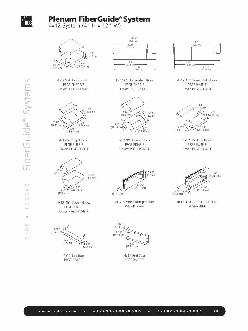
5/
05
•
1
00
56
9Fi
ber
Gu
ide®
Syst
ems
79w w w . a d c . c o m • + 1 - 9 5 2 - 9 3 8 - 8 0 8 0 • 1 - 8 0 0 - 3 6 6 - 3 8 9 1
Plenum FiberGuide® System4x12 System (4" H x 12" W)
4.0"(10.16 cm) 12.0"
(30.48 cm)
7.44"(18.9 cm)
7.44"(18.9 cm)
12.51"(31.78 cm) 2.2"
(5.59 cm)
4.12"(10.46 cm)
13.63"(34.62 cm)
12.0"(30.48 cm)
14.13"(35.89 cm)
12.0"(30.48 cm)
4.0"(10.16 cm)
7.01"(17.81 cm)
5.8"(14.73 cm)
17.36"(44.1 cm)
3.6"(9.14 cm)
6.65"(16.9 cm)
1.24"(3.15 cm)
4.11"(10.44 cm)
12.22"(31.04 cm)
12.0"(30.48 cm)
4.0"(10.16 cm)
7.46"(18.95 cm)
7.46"(18.95 cm)
5.63"(14.3 cm)
12.0"(30.48 cm)
4.0"(10.16 cm)6.93"
(17.6 cm)
17.36"(44.09 cm)3.6"
(9.14 cm)
9.4"(23.88 cm)
4x12/4x6 Horizontal TPFGF-PHRT-F/B
Cover: PFGC-PHRT-F/B
12" 90° Horizontal ElbowPFGF-PH9E-F
Cover: PFGC-PH9E-F
4x12 45° Horizontal ElbowPFGF-PH4E-F
Cover: PFGC-PH4E-F
4x12 90° Up ElbowPFGF-PUPE-F
Cover: PFGC-PUPE-F
4x12 90° Down ElbowPFGF-PDNE-F
Cover: PFGC-PDNE-F
4x12 45° Up ElbowPFGF-PU4E-F
Cover: PFGC-PU4E-F
4x12 45° Down ElbowPFGF-PD4E-F
Cover: PFGC-PD4E-F
4x12 3 Sided Trumpet FlarePFGF-PTRM-F
4x12 4 Sided Trumpet FlarePFGF-PFPT-F
4x12 Junction PFGF-PJWR-F
4x12 End CapPFGF-PMEC-F
15.44"(39.22 cm)
12.87"(32.69 cm)
4.0"(10.16 cm)
15.44"(39.22 cm)
12.0"(30.48 cm)
12.56"(31.9 cm)
15.95"(40.51 cm)

5/
05
•
1
00
56
9Fi
ber
Gu
ide®
Syst
ems
80w w w . a d c . c o m • + 1 - 9 5 2 - 9 3 8 - 8 0 8 0 • 1 - 8 0 0 - 3 6 6 - 3 8 9 1
8.21"(20.85 cm)
2.31"(5.87 cm)
2.31"(5.87 cm)
36.07"(91.62 cm)
2.31"(5.87 cm)
2.31"(5.87 cm)
18.84"(47.85 cm)
2.31"(5.87 cm)
2.31"(5.87 cm)
Short bracket kitfor use with 2x2 and 4x6 sizes; 8.21" overall length
Short bracket kit with square U-bolt for easy access mounting
Long bracket kitfor use with 2x2, 4x6, and 4x12 sizes; 18.84" overall length
Long bracket kit with square U-bolt for easy access mounting
Span bracket kitfor use with 2x2, 4x6, and 4x12 sizes; spans 24" center to center floor struts
Span bracket kit with square U-bolt for easy access mounting
Diagonal span bracket kitfor use with 2x2, 4x6, and 4x12 sizes; spans diagonally up to 34" between struts
Diagonal span bracket kit with square U-bolt for easy access mounting
PFGF-SSPT-C/B
PFGF-EASSPT-C/B
PFGF-LSPT-C/B/F
PFGF-EALSPT-C/B/F
PFGF-ESPT-C/B/F
PFGF-EAESPT-C/B/F
PFGF-DSPT-C/B/F
PFGF-EADSPT-C/B/F
Description Catalog Number
O r d e r i n g I n f o r m a t i o n
Plenum FiberGuide® SystemAccessories (Support Bracket Kits)
18.84"(47.85 cm)
2.31"(5.87 cm)
2.31"(5.87 cm) 26.13"
(66.37 cm)
2.31"(5.87 cm)
2.31"(5.87 cm)
8.21"(20.85 cm)
2.31"(5.87 cm)
2.31"(5.87 cm)
36.07"(91.62 cm)
2.31"(5.87 cm)
2.31"(5.87 cm)
26.13"(66.37 cm)
All support bracket kits fit round support pedestals sizes .5" to 1.125".
Short Bracket Kit withSquare U-bolt
PFGF-EASSPT-C/B
Long Bracket Kit withSquare U-bolt
PFGF-EALSPT-C/B/F
Span Bracket Kit withSquare U-bolt
PFGF-EAESPT-C/B/F
Diagonal Span Bracket Kitwith Square U-boltPFGF-EADSPT-C/B/F
Short Bracket KitPFGF-SSPT-C/B
Long Bracket KitPFGF-LSPT-C/B/F
Span Bracket KitPFGF-ESPT-C/B/F
Diagonal Span Bracket KitPFGF-DSPT-C/B/F

5/
05
•
1
00
56
9Fi
ber
Gu
ide®
Syst
ems
81w w w . a d c . c o m • + 1 - 9 5 2 - 9 3 8 - 8 0 8 0 • 1 - 8 0 0 - 3 6 6 - 3 8 9 1
Plenum FiberGuide® SystemAccessories (Flexible Tubing)
Plenum metallic 2-inch (5.08 cm) inner diameter flexible tubing is available for use in under floorapplications where the exact layout of drop locations has not yet been defined, or where frequent changesin equipment location are expected. In future growth applications, the flexible tubing can be installed upfront, and coiled under the floor until the exact configuration of equipment is established. The flexibletubing can then be routed to the drop location and fed through the flooring to the final location.
Flexible tubing options include a two-hose adapter that can be attached to 6-inch (15.24 cm) standardfitting or straight section. The two-hose adapter comes complete with two 5-foot-long (1.53 m) flexiblehoses, and two end finishing couplers. When longer flexible tube requirements exist, multiple 5-foot-longextension tubes can be spliced into the two hose adapter to reach any length. The extension tubes are 5feet (1.53 m) long, and come with a splice coupler. Additional finishing couplers, mounting straps andsplice couplers can be purchased separately.
Extension TubePFGF-HEXT
Finishing CouplerPFGF-HFIN
Splicing CouplerPFGF-HSPL
Two Hose AdapterPFGF-KT03-B
One Hose AdapterPFGF-KT03-C
Mounting StrapPFGF-HMST
One hose adapter, with 5' (1.53 m) hoses and finishing couplersFor use with 2x2 openings
Two hose adapter, with 5' (1.53 m) hoses and finishing couplersFor use with 4x6 openings
Extension tube, 5' (1.53 m) long with splice coupler
Finishing coupler
Mounting strap
Splicing coupler
Flexible tubing, 2" (5.08 cm) inner diameter(X = length in feet: 5, 15, 35, 75, 110, 150)
PFGF-KT03-C
PFGF-KT03-B
PFGF-HEXT
PFGF-HFIN
PFGF-HMST
PFGF-HSPL
PFGF-MIDY-XF
Description Catalog Number
O r d e r i n g I n f o r m a t i o n

Index
82w w w . a d c . c o m • + 1 - 9 5 2 - 9 3 8 - 8 0 8 0
5/
05
•
1
00
56
9Fi
ber
Gu
ide®
Syst
ems
FGS-ACC063 ............................42
FGS-ASRI ......................25, 31, 57
FGS-ASRI-10F ......................24, 30
FGS-ASRI-15F ......................24, 30
FGS-ASRI-5F ........................24, 30
FGS-BTBL-C ........................44, 64
FGS-BTBS-C ........................44, 64
FGS-CD4E-A ..............................22
FGS-CD4E-B ..............................28
FGS-CD9E-A ..............................22
FGS-CD9E-B ..............................28
FGS-CDSA-AB......................22, 28
FGS-CH4E-A ..............................22
FGS-CH4E-B ..............................28
FGS-CH9E-A ..............................22
FGS-CH9E-B ..............................28
FGS-CHRT-A ..............................22
FGS-CHRT-B ..............................28
FGS-CHXP-A ..............................22
FGS-CHXP-B ..............................28
FGS-CLIP-D ................................43
FGS-CLIP-E ................................43
FGS-DHCP ..........................20, 32
FGS-DHHC ................................26
FGS-HAEJ-C ..............................45
FGS-HASB ..................................50
FGS-HASB-1/2-36 ......................50
FGS-HASB-1/2-48 ......................50
FGS-HASB-5/8-36 ......................50
FGS-HASB-5/8-48 ......................50
FGS-HASK-C ........................45, 64
FGS-HCBL ..................................66
FGS-HCBL-12 ............................46
FGS-HCBL-15 ............................46
FGS-HDCB-C........................44, 64
FGS-HDGR ..........................50, 66
FGS-HDLB-4 ........................46, 66
FGS-HDSI-AB ....24, 25, 30, 31, 57
FGS-HDSI-F/C ............................36
FGS-HDSI-F/D ......................36, 37
FGS-HETP-F-XX ..........................47
FGS-HETR ..................................65
FGS-HETR-5/8-A ........................46
FGS-HETR-F-XX....................47, 67
FGS-HETR-XX ............................46
FGS-HETR-XX-A ........................65
FGS-HFCK ..................................50
FGS-HFCK-1/2............................50
FGS-HFCK-5/8............................50
FGS-HFRR-10 ......................48, 49
FGS-HHEC-10 ......................48, 49
FGS-HHGK ..........................48, 49
FGS-HIFC-A................................48
FGS-HIFC-B ................................48
FGS-HIFC-F ................................48
FGS-HKFM-XX............................50
FGS-HKW2-E..............................43
FGS-HLBK ............................46, 66
FGS-HLDR ..................................50
FGS-HLDR-A ..............................50
FGS-HLDR-XX ............................50
FGS-HLR2-C ........................44, 64
FGS-HMEC-A ......................22, 23
FGS-HMEC-B ......................28, 29
FGS-HMEC-C ............................15
FGS-HMEC-E..............................43
FGS-HMEC-F..................34, 35, 61
FGS-HMEC-G ............................18
FGS-HNLR-AB ......................46, 65
FGS-HNLR-F ........................47, 67
FGS-HNTP-F ..............................67
FGS-HNTP-F-XX..........................47
FGS-HNTR ..................................65
FGS-HNTR-5/8-A ........................46
FGS-HNTR-F-XX ..................47, 67
FGS-HNTR-XX ............................46
FGS-HNTS ..................................66
FGS-HNTS-F-XX....................47, 67
FGS-HNTS-F-XX-LP ..............47, 67
FGS-HNTS-LP..............................66
FGS-HNTS-XX ............................46
FGS-HNTS-XX-LP........................46
FGS-HOMX-16MM ..............46, 65
FGS-HRJA-A/B/F ........................48
FGS-HSDI-F/D ............................37
FGS-HSHC-10 ............................16
FGS-HTHR ..................................50
FGS-HTHR-1/2-12 ......................50
FGS-HTHR-1/2-30 ......................50
FGS-HTHR-1/2-72 ......................50
FGS-HTHR-5/8-12 ......................50
FGS-HTHR-5/8-30 ......................50
FGS-HTHR-5/8-72 ......................50
FGS-HTHR-XX-NN ......................50
FGS-HTR2 ..................................64
FGS-HTR2-1/2 ............................45
FGS-HTR2-12MM ......................45
FGS-HTR2-2-5/8 ........................45
FGS-HTR2-5/8 ............................45
FGS-HTR2-XX ............................45
FGS-HTUB ..................................66
FGS-HTUB-F-XX ..................47, 67
FGS-HTUB-XX ............................46
FGS-HUFB-A ........................46, 65
FGS-HUFB-C ........................44, 64
FGS-HVHG ....................26, 32, 48
FGS-HWMB-C............................42
FGS-HWMB-D............................43
FGS-ISLAND-F ................36, 37, 62
FGS-ISLAND-F-513 ....................36
FGS-ISLAND3-F ..............36, 37, 62
FGS-JUNC ....................................9
FGS-JUNC-A ..............................27
FGS-JUNC-B ........................33, 39
FGS-JUNC-F ..............................39
FGS-JUNC-G ........................21, 54
FGS-KDH2-C........................16, 52
FGS-KQKB ..............26, 32, 48, 49
FGS-KT03-A ............24, 25, 30, 31
FGS-KT03-A1 ..........24, 25, 30, 31
Note: Numbers in italics and gray represent engineering line drawing

Index
83w w w . a d c . c o m • + 1 - 9 5 2 - 9 3 8 - 8 0 8 0
5/
05
•
1
00
56
9Fi
ber
Gu
ide®
Syst
ems
FGS-KT03-A1-10F................24, 30
FGS-KT03-A1-15F................24, 30
FGS-KT03-A10F ..................24, 30
FGS-KT03-A15F ..................24, 30
FGS-KT03-A4 ......................25, 31
FGS-KT03-A4-10F................24, 30
FGS-KT03-A4-15F................24, 30
FGS-KT03-A4-5F..................24, 30
FGS-KT03-B ........................36, 37
FGS-KT03-B-10F ........................36
FGS-KT03-B-15F ........................36
FGS-KT03-C ........................16, 41
FGS-KT03-C-10F..................16, 41
FGS-KT03-C-15F..................16, 41
FGS-KT03-G-SF ..........................18
FGS-KT07-A4-10F................24, 30
FGS-KT07-A4-15F................24, 30
FGS-KT07-A4-5F..................24, 30
FGS-KT09 ..................................48
FGS-KTW1-C..............................42
FGS-KTW1-CA ..........................42
FGS-KTW1-E ..............................42
FGS-KTW2-D..............................43
FGS-KTW2-E ..............................43
FGS-KTW4-C..............................42
FGS-KTW4-E ..............................42
FGS-MCDS-AB ........24, 25, 30, 31
FGS-MCDS-EX-AB................24, 30
FGS-MD4A-C ......................15, 52
FGS-MD4E-A ................22, 23, 56
FGS-MD4E-B..................28, 29, 58
FGS-MD4E-F ..................34, 35, 60
FGS-MD4E-G ................18, 19, 54
FGS-MD9A-C ......................15, 52
FGS-MD9E-A ................22, 23, 55
FGS-MD9E-B..................28, 29, 58
FGS-MD9E-F ..................34, 35, 60
FGS-MD9E-G ................18, 19, 53
FGS-MDRT-F ..................36, 37, 62
FGS-MDSA-AB ..22, 23, 28, 29, 56
FGS-MDSA-AC ....................15, 52
FGS-MDSA-F2B..............34, 35, 61
FGS-MDSA-FB ..28, 29, 34, 35, 61
FGS-MDSA-FB-L ..................34, 35
FGS-MDSA-FB-R ..................34, 35
FGS-MDSA-GA ..............18, 19, 54
FGS-MDSA-GB ..............18, 19, 54
FGS-MDSP-2B......................30, 31
FGS-MDSP-2B-IMP ..............30, 31
FGS-MDSP-A ................24, 25, 56
FGS-MDSP-A/I......................24, 25
FGS-MDSP-B..................30, 31, 59
FGS-MDSP-B/I ......................30, 31
FGS-MDSP-C..............................16
FGS-MDSP-EX-A ............24, 25, 56
FGS-MDSP-EX-B ............30, 31, 59
FGS-MDSP-F ............34, 36, 37, 61
FGS-MDSP-F-VS ........................34
FGS-MDSP-F/I ............................36
FGS-MDSP-G ................18, 19, 53
FGS-MEX1-C-10F ................16, 41
FGS-MEX1-C-15F ................16, 41
FGS-MEX1-C-5F ..................16, 41
FGS-MEXC-E-A ..........................40
FGS-MEXC-E-A/B/F ....................40
FGS-MEXC-E-B ..........................40
FGS-MEXC-E-F ..........................40
FGS-MEXP-A/B/F ..................41, 63
FGS-MEXP-E-A/B/F ..............40, 63
FGS-MEXP-LP-A/B/F ............41, 63
FGS-MEXP-LP-G ..................18, 54
FGS-MFAW-A ............................57
FGS-MFAW-B ............................59
FGS-MFAW-F ............................62
FGS-MFAW-X ..............................9
FGS-MFIN-10 ......................48, 49
FGS-MFTY..................................49
FGS-MFTY-XF ............................48
FGS-MH4A-C ......................15, 51
FGS-MH4E-A ................22, 23, 55
FGS-MH4E-B..................28, 29, 58
FGS-MH4E-F ..................34, 35, 60
FGS-MH4E-G ................18, 19, 53
FGS-MH9A-C ......................15, 51
FGS-MH9A-C-45/2 ..............15, 51
FGS-MH9E-A ................22, 23, 55
FGS-MH9E-B..................28, 29, 58
FGS-MH9E-F ..................34, 35, 60
FGS-MH9E-F-VS ........................34
FGS-MH9E-G ................18, 19, 53
FGS-MHIS-A ..................22, 23, 56
FGS-MHIS-B ..................28, 29, 59
FGS-MHIS-F ..................34, 35, 61
FGS-MHIS-JIG-A/B/F22, 23, 28, 29,34, 35
FGS-MHRT-A..................22, 23, 55
FGS-MHRT-B ..................28, 29, 58
FGS-MHRT-F ..................34, 35, 60
FGS-MHRT-F-VS..........................34
FGS-MHRT-F/B ..............34, 35, 60
FGS-MHRT-F/B-VS ......................34
FGS-MHRT-G ................18, 19, 53
FGS-MHTA-C ......................15, 51
FGS-MHXP-A ................22, 23, 55
FGS-MHXP-B ................28, 29, 58
FGS-MHXP-B/F ....................34, 35
FGS-MHXP-B/F-VS......................34
FGS-MHXP-C ......................15, 51
FGS-MHXP-F..................34, 35, 60
FGS-MHXP-F-VS ........................34
FGS-MHXP-F/B ..........................61
FGS-MHXP-G ................18, 19, 53
FGS-MIDY ..................................49
FGS-MIDY-XF ............................48
FGS-MISY-XF ..............................48
FGS-MJWR-A ......9, 24, 25, 30, 31
FGS-MJWR-C ............................17
FGS-MJWR-D ............................43
FGS-MKIT ..................................48
FGS-MKIT-ABF......................48, 49
Note: Numbers in italics and gray represent engineering line drawing

Index
84w w w . a d c . c o m • + 1 - 9 5 2 - 9 3 8 - 8 0 8 0
5/
05
•
1
00
56
9Fi
ber
Gu
ide®
Syst
ems
FGS-MLDY-XF ............................48
FGS-MSCS-A..............................56
FGS-MSDS-C........................16, 52
FGS-MSHA-C ......................17, 52
FGS-MSHC-B..............................32
FGS-MSHC-C ............................42
FGS-MSHC-D ............................43
FGS-MSHS-A........................26, 57
FGS-MSHS-B ........................32, 59
FGS-MSHS-C..............................42
FGS-MSHS-CA ..........................42
FGS-MSHS-D..............................43
FGS-MSHS-F ........................38, 62
FGS-MSHS-G ......................20, 54
FGS-MSHS-STOR-B ..............32, 59
FGS-MSHS-STOR-F ..............38, 62
FGS-MSNC-A ......................26, 57
FGS-MSNC-B/G ......20, 32, 54, 59
FGS-MSNC-F........................38, 62
FGS-MSSC-A........................26, 56
FGS-MSSC-B/G........20, 32, 54, 59
FGS-MSSC-F ..............................38
FGS-MSTOR-A/B/F................48, 49
FGS-MTRM ................................37
FGS-MTRM-2B ....................30, 31
FGS-MTRM-2B-IMP..............30, 31
FGS-MTRM-A....24, 25, 30, 31, 57
FGS-MTRM-B ................36, 37, 59
FGS-MTRM-C ......................16, 41
FGS-MTRM-F ................36, 37, 61
FGS-MTRM-G ................18, 19, 54
FGS-MU4A-C ......................15, 51
FGS-MU4E-A ................22, 23, 56
FGS-MU4E-B..................28, 29, 58
FGS-MU4E-F ..................34, 35, 60
FGS-MU4E-G ................18, 19, 53
FGS-MU9A-C ......................15, 52
FGS-MU9E-A ................22, 23, 55
FGS-MU9E-B..................28, 29, 58
FGS-MVAR-A ..........22, 23, 26, 56
FGS-MVAR-B ..........28, 29, 32, 59
FGS-MVAR-F............34, 35, 38, 61
FGS-OHHC ................................26
FGS-SD4E-A ..............................22
FGS-SD4E-B ..............................28
FGS-SD4E-F................................34
FGS-SD9E-A ..............................22
FGS-SD9E-B ..............................28
FGS-SD9E-F................................34
FGS-SDSA-AB ......................22, 28
FGS-SDSA-F2B ..........................34
FGS-SDSA-FB ................28, 29, 34
FGS-SDSP-F..........................36, 37
FGS-SH4E-A ........................22, 23
FGS-SH4E-B ..............................28
FGS-SH4E-F................................34
FGS-SH9E-A ..............................22
FGS-SH9E-B ..............................28
FGS-SH9E-F................................34
FGS-SHRT-A................................22
FGS-SHRT-B................................28
FGS-SHRT-F ................................34
FGS-SHRT-F/B ............................34
FGS-SHXP-A ..................22, 73, 74
FGS-SHXP-B ..............................28
FGS-SHXP-B/F ............................34
FGS-SHXP-F................................34
FGS-SU4E-A ..............................22
FGS-SU4E-B ..............................28
FGS-SU4E-F................................34
FGS-SU9E-A ..............................22
FGS-VDSA-FB-L ..........................34
FGS-VDSA-FB-R..........................34
FGSO-ACC063 ..........................42
FGSO-ASRI-10F ....................24, 30
FGSO-ASRI-15F ....................24, 30
FGSO-ASRI-5F ......................24, 30
FGSO-DHHC ..............................32
FGSO-HMEC-C ..........................15
FGSO-ISLAND-F..........................36
FGSO-ISLAND-F-513 ..................36
FGSO-ISLAND3-F........................36
FGSO-JUNC-A............................27
FGSO-JUNC-B ............................33
FGSO-JUNC-F ............................39
FGSO-KDH2-C ..........................16
FGSO-KT03-A ......................24, 30
FGSO-KT03-A1 ....................24, 30
FGSO-KT03-A1-10F ............24, 30
FGSO-KT03-A1-15F ............24, 30
FGSO-KT03-A10F ................24, 30
FGSO-KT03-A15F ................24, 30
FGSO-KT03-A4-10F ............24, 30
FGSO-KT03-A4-15F ............24, 30
FGSO-KT03-A4-5F ..............24, 30
FGSO-KT03-B ............................36
FGSO-KT03-B-10F......................36
FGSO-KT03-B-15F......................36
FGSO-KT03-C ......................16, 41
FGSO-KT03-C-10F ..............16, 41
FGSO-KT03-C-15F ..............16, 41
FGSO-KT07-A4-10F ............24, 30
FGSO-KT07-A4-15F ............24, 30
FGSO-KT07-A4-5F ..............24, 30
FGSO-KTW1-C ..........................42
FGSO-KTW1-CA ........................42
FGSO-KTW1-E............................42
FGSO-KTW2-D ..........................43
FGSO-KTW2-E............................43
FGSO-KTW4-C ..........................42
FGSO-KTW4-E............................42
FGSO-MCDS-AB ..................24, 30
FGSO-MCDS-EX-AB ............24, 30
FGSO-MD4A-C ..........................15
FGSO-MD4E-A ..........................22
FGSO-MD4E-B ..........................28
FGSO-MD4E-F............................34
FGSO-MD9A-C ..........................15
FGSO-MD9E-A ..........................22
FGSO-MD9E-B ..........................28
Note: Numbers in italics and gray represent engineering line drawing

Index
85w w w . a d c . c o m • + 1 - 9 5 2 - 9 3 8 - 8 0 8 0
5/
05
•
1
00
56
9Fi
ber
Gu
ide®
Syst
ems
FGSO-MD9E-F............................34
FGSO-MDRT-F ............................36
FGSO-MDSA-AB ..................22, 28
FGSO-MDSA-AC........................15
FGSO-MDSA-F ..........................34
FGSO-MDSA-F2B ......................34
FGSO-MDSA-FB ........................28
FGSO-MDSP-2B..........................30
FGSO-MDSP-2B-IMP ..................30
FGSO-MDSP-A ..........................24
FGSO-MDSP-A/I ........................24
FGSO-MDSP-B............................30
FGSO-MDSP-B/I..........................30
FGSO-MDSP-C ..........................16
FGSO-MDSP-EX-A......................24
FGSO-MDSP-EX-B ......................30
FGSO-MDSP-F ............................36
FGSO-MDSP-F/I ..........................36
FGSO-MEX1-C-10F ..............16, 41
FGSO-MEX1-C-15F ..............16, 41
FGSO-MEX1-C-5F ................16, 41
FGSO-MEXC-E-A........................40
FGSO-MEXC-E-A/B/F ..................40
FGSO-MEXC-E-B ........................40
FGSO-MEXC-E-F ........................40
FGSO-MEXP-A/B/F......................41
FGSO-MEXP-E-A/B/F ..................40
FGSO-MEXP-LP-A/B/F ................41
FGSO-MFTY-XF ..........................48
FGSO-MH4A-C ..........................15
FGSO-MH4E-A ..........................22
FGSO-MH4E-B ..........................28
FGSO-MH4E-F............................34
FGSO-MH9A-C ..........................15
FGSO-MH9A-C-45/2..................15
FGSO-MH9E-A ..........................22
FGSO-MH9E-B ..........................28
FGSO-MH9E-F............................34
FGSO-MHIS-A ............................22
FGSO-MHIS-B ............................28
FGSO-MHIS-F ............................34
FGSO-MHRT-A ..........................22
FGSO-MHRT-B............................28
FGSO-MHRT-F ............................34
FGSO-MHRT-F/B ........................34
FGSO-MHTA-C ..........................15
FGSO-MHXP-A ..........................22
FGSO-MHXP-B ..........................28
FGSO-MHXP-B/F ........................34
FGSO-MHXP-C ..........................15
FGSO-MHXP-F............................34
FGSO-MIDY-XF ..........................48
FGSO-MISY-XF ..........................48
FGSO-MJWR-A ....................24, 30
FGSO-MJWR-C ..........................17
FGSO-MJWR-D ..........................43
FGSO-MLDY-XF..........................48
FGSO-MSDS-C ..........................16
FGSO-MSHA-C ..........................17
FGSO-MSHC-A ..........................26
FGSO-MSHC-B ..........................32
FGSO-MSHC-C ..........................42
FGSO-MSHC-D ..........................43
FGSO-MSHS-A ..........................26
FGSO-MSHS-B............................32
FGSO-MSHS-C ..........................42
FGSO-MSHS-CA ........................42
FGSO-MSHS-D ..........................43
FGSO-MSHS-F ............................38
FGSO-MSHS-STOR-B..................32
FGSO-MSHS-STOR-F ..................38
FGSO-MSNC-A ..........................26
FGSO-MSNC-B/G ......................32
FGSO-MSNH-F ..........................38
FGSO-MSSC-A ..........................26
FGSO-MSSC-B/G........................32
FGSO-MSSC-F ............................38
FGSO-MTRM-2B ........................30
FGSO-MTRM-2B-IMP ................30
FGSO-MTRM-A....................24, 30
FGSO-MTRM-B ..........................36
FGSO-MTRM-C....................16, 41
FGSO-MTRM-F ..........................36
FGSO-MU4A-C ..........................15
FGSO-MU4E-A ..........................22
FGSO-MU4E-B ..........................28
FGSO-MU4E-F............................34
FGSO-MU9A-C ..........................15
FGSO-MU9E-A ..........................22
FGSO-MU9E-B ..........................28
FGSO-MVAR-A ....................22, 26
FGSO-MVAR-B ....................28, 32
FGSO-MVAR-F ....................34, 38
FGSO-SD4E-A ............................22
FGSO-SD4E-B ............................28
FGSO-SD4E-F ............................34
FGSO-SD9E-A ............................22
FGSO-SD9E-B ............................28
FGSO-SD9E-F ............................34
FGSO-SDSA-AB....................22, 28
FGSO-SDSA-F2B ........................34
FGSO-SDSA-FB ....................28, 34
FGSO-SDSP-F ............................36
FGSO-SH4E-A ............................22
FGSO-SH4E-B ............................28
FGSO-SH4E-F ............................34
FGSO-SH9E-A ............................22
FGSO-SH9E-B ............................28
FGSO-SH9E-F ............................34
FGSO-SHRT-A ............................22
FGSO-SHRT-B ............................28
FGSO-SHRT-F..............................34
FGSO-SHRT-F/B ..........................34
FGSO-SHXP-A ............................22
FGSO-SHXP-B ............................28
FGSO-SHXP-B/F ..........................34
FGSO-SHXP-F ............................34
FGSO-SU4E-A ............................22
FGSO-SU4E-B ............................28
FGSO-SU4E-F ............................34
Note: Numbers in italics and gray represent engineering line drawing

Index
86w w w . a d c . c o m • + 1 - 9 5 2 - 9 3 8 - 8 0 8 0
5/
05
•
1
00
56
9Fi
ber
Gu
ide®
Syst
ems
FGSO-SU9E-A ............................22
PFGC-PD4E-B ......................76, 77
PFGC-PD4E-C ......................74, 75
PFGC-PD4E-F ......................78, 79
PFGC-PDNE-B ......................76, 76
PFGC-PDNE-C......................74, 75
PFGC-PDNE-F ......................78, 79
PFGC-PDSA-B/F....................76, 77
PFGC-PDSA-C/B ..................74, 75
PFGC-PDSA-C/F ..................74, 75
PFGC-PH4E-B ......................76, 77
PFGC-PH4E-C ......................73, 74
PFGC-PH4E-F ......................78, 79
PFGC-PH9E-B ......................76, 77
PFGC-PH9E-C ......................74, 75
PFGC-PH9E-F ......................78, 79
PFGC-PHRT-B ......................76, 76
PFGC-PHRT-C ......................74, 74
PFGC-PHRT-F........................78, 78
PFGC-PHRT-F/B ....................78, 79
PFGC-PHXP-B ......................76, 76
PFGC-PHXP-C ......................74, 74
PFGC-PHXP-F ......................78, 78
PFGC-PSHS-B ......................76, 76
PFGC-PSHS-C ......................74, 74
PFGC-PSHS-F ......................78, 78
PFGC-PU4E-B ......................76, 77
PFGC-PU4E-C ......................74, 75
PFGC-PU4E-F ......................78, 79
PFGC-PUPE-B ......................76, 77
PFGC-PUPE-C ......................74, 75
PFGC-PUPE-F ......................78, 79
PFGF-DSPT-C/B/F ..................80, 80
PFGF-EADSPT-C/B/F ..............80, 80
PFGF-EAESPT-C/B/F ..............80, 80
PFGF-EALSPT-C/B/F ..............80, 80
PFGF-EASSPT-C/B ................80, 80
PFGF-ESPT-C/B/F ..................80, 80
PFGF-HEXT ................................81
PFGF-HFIN..................................81
PFGF-HMST................................81
PFGF-HSPL..................................81
PFGF-KT03-B..............................81
PFGF-KT03-C ............................81
PFGF-LSPT-C/B/F ..................80, 80
PFGF-MIDY-XF............................81
PFGF-PD4E-B........................76, 77
PFGF-PD4E-C ......................74, 75
PFGF-PD4E-F ........................78, 79
PFGF-PDNE-B ......................76, 77
PFGF-PDNE-C ......................74, 75
PFGF-PDNE-F........................78, 79
PFGF-PDSA-B/F ....................76, 77
PFGF-PDSA-C/B....................74, 75
PFGF-PDSA-C/F ....................74, 75
PFGF-PFPT-B ........................76, 77
PFGF-PFPT-C ........................74, 75
PFGF-PFPT-F..........................78, 79
PFGF-PH4E-B........................76, 77
PFGF-PH4E-C ......................74, 75
PFGF-PH4E-F ........................78, 79
PFGF-PH9E-B........................76, 77
PFGF-PH9E-C ......................74, 75
PFGF-PH9E-F ........................78, 79
PFGF-PHRT-B ........................76, 76
PFGF-PHRT-C........................74, 74
PFGF-PHRT-F ........................78, 78
PFGF-PHRT-F/B ....................78, 79
PFGF-PHXP-B ......................76, 76
PFGF-PHXP-C ......................74, 74
PFGF-PHXP-F........................78, 78
PFGF-PJWR-B ......................76, 77
PFGF-PJWR-C ......................74, 75
PFGF-PJWR-F........................78, 79
PFGF-PMEC-B ......................76, 77
PFGF-PMEC-F ......................78, 79
PFGF-PPSC-B........................76, 77
PFGF-PSEE-B/C ....................72, 73
PFGF-PSEE-BLK ....................72, 73
PFGF-PSHS-B........................76, 77
PFGF-PSHS-C ......................74, 74
PFGF-PSHS-F ........................78, 78
PFGF-PSHS-KT......................72, 73
PFGF-PSHS-KT-F ..................72, 73
PFGF-PTRM-B ......................74, 75
PFGF-PTRM-C ......................74, 75
PFGF-PTRM-F ......................78, 79
PFGF-PU4E-B........................76, 77
PFGF-PU4E-C ......................74, 75
PFGF-PU4E-F ........................78, 79
PFGF-PUPE-B........................76, 77
PFGF-PUPE-C ......................74, 75
PFGF-PUPE-F ........................78, 79
PFGF-SSPT-C/B......................80, 80
Note: Numbers in italics and gray represent engineering line drawing

ADC Telecommunications, Inc., P.O. Box 1101, Minneapolis, Minnesota USA 55440-1101Specifications published here are current as of the date of publication of this document. Because we are continuouslyimproving our products, ADC reserves the right to change specifications without prior notice. At any time, youmay verify product specifications by contacting our headquarters office in Minneapolis. ADC Telecommunications,Inc. views its patent portfolio as an important corporate asset and vigorously enforces its patents. Products orfeatures contained herein may be covered by one or more U.S. or foreign patents. An Equal Opportunity Employer
100569 5/05 Revision © 1995, 1997, 1998, 2000, 2001, 2002, 2003, 2004, 2005 ADC Telecommunications, Inc. All Rights Reserved
Web Site: www.adc.comFrom North America, Call Toll Free: 1-800-366-3891 • Outside of North America: +1-952-938-8080 Fax: +1-952-917-3237 • For a listing of ADC’s global sales office locations, please refer to our web site.
Fib
erG
uid
e®Sy
stem
s