FF Cable Specs 13-2009-ffieuc-leoni-alexander_weiss.pdf
27
1 © 2009 Fieldbus Foundation Dr. Alexander Weiss Business Unit Industrial Projects LEONI Kerpen GmbH Foundation Fieldbus Cable Specification FF-844 Status & Outlook
-
Upload
kantilal-malwania -
Category
Documents
-
view
12 -
download
0
Transcript of FF Cable Specs 13-2009-ffieuc-leoni-alexander_weiss.pdf

1© 2009 Fieldbus Foundation
Dr. Alexander Weiss
Business Unit Industrial Projects
LEONI Kerpen GmbH
Foundation FieldbusCable Specification FF-844
Status & Outlook

2 © 2009 Fieldbus FoundationDr. Weiss, LEONI Kerpen GmbH
�Introduction�Standards for Fieldbus Cables�Intrinsic Safety Concept�Requirements for Foundation Fieldbus�Cable Design and Materials�Fire Behaviour �Installation�Product Overview ICON�Bus for Foundation Fieldbus
�Conclusion & Outlook
Overview

3 © 2009 Fieldbus FoundationDr. Weiss, LEONI Kerpen GmbH
�Foundation Fieldbus�Cables based on one common standard
– defined cable design parameters– defined electrical properties
to�cover different Fieldbus applications�guarantee high quality level of product�enable users to easily select the right cable for their
application
Introduction

4 © 2009 Fieldbus FoundationDr. Weiss, LEONI Kerpen GmbH
�Standards for Foundation Fieldbus cables�Cable specification Foundation Fieldbus FF-844 H1 �Cable design based on EN 50288-7 or UL 13 / UL 2250
– no listing for EN type products– UL type products may be UL listed
�Electrical properties: FF-844 H1 and IEC 61158-2, type A– IEC 61158-2, type A
� has the most severe requirements,� restricted to singlepairs, whereas FF-844 H1 specifies multipairs, too� IEC 61158-2 types B to D should not be referred to for fieldbus cables
– FF-844 H1� electrical properties of each pair in multipair cables shall be according
to IEC 61558-2, type A
Standards

5 © 2009 Fieldbus FoundationDr. Weiss, LEONI Kerpen GmbH
�Standards for Foundation Fieldbus cables�Demands on intrinsically safe cables and installations
– IEC 600079-14, Intrinsically Safe Cables– IEC 600079-27, Field Intrinsically Safe COncept (FISCO)
Standards

6 © 2009 Fieldbus FoundationDr. Weiss, LEONI Kerpen GmbH
�The Basic Principle of Ignition Protection Intrinsically Safe “i”�For the ignition of a potentially explosive atmosphere a
specific energy is necessary.�The ignition protection intrinsically safe makes sure that
the “existing” energy can not ignite the explosive atmosphere.
�An intrinsically safe electric circuit may not be the reason for an ignition. This applies for normal operating conditions and in case of faults (e.g. short circuits).
Intrinsic Safety

7 © 2009 Fieldbus FoundationDr. Weiss, LEONI Kerpen GmbH
�Classification of hazardous areas (“zones”) according to IEC 60079-14�Classification depending on risk of ignition
– Zones 0, 1 & 2classify explosive atmosphere of air / flammable gas, vapour or mist
– Zones 20, 21 & 22classify explosive atmosphere of air / cloud of combustible dust
�Zones 0 & 20: permanent risk�Zones 1 & 21: occasional risk�Zones 2 & 22: risk not likely; when occurring, will persist
only for short period
Intrinsic Safety

8 © 2009 Fieldbus FoundationDr. Weiss, LEONI Kerpen GmbH
�Device category ia and ib, according to standard IEC 60079-11�Category ia suitable for Zone O:
– In case of 2 independent faults it is not allowed to have an ignition.
� Category ib suitable for Zone 1 and 2:– In case of 1 fault it is not allowed to have an ignition.
Intrinsic Safety

9 © 2009 Fieldbus FoundationDr. Weiss, LEONI Kerpen GmbH
�Demands on Intrinsically Safe Cables according to IEC 60079-14�Flame retardant according to IEC 60332-1
(unless the cables are laid in earth, in sand-filled trenches/ducts or otherwise protected against flame propagation)
�Mutual capacitance: max. 200 pF/m�Inductance: max. 1 μH/m or L/R-Ratio: max. 30 μH/Ohm
(L: loop inductance / R: Loop resistance) �Radial thickness of insulation: min. 0.2 mm�Test Voltage Ueff: min. 500 V�Diameter of conductor: min. 0.1 mm, has to be applied for
single strands of e.g. multistranded conductor too
Intrinsic Safety

10 © 2009 Fieldbus FoundationDr. Weiss, LEONI Kerpen GmbH
�Standard IEC 60079-27, FISCO and FNICO�Field Non-Incendive COncept (FNICO)�Field Intrinsically Safe COncept (FISCO)
– Demands on ignition protection intrinsically safe IS– All participants in the bus (devices) must be “FISCO”-approved– Every field device takes up a constant basic current of at least 10mA– Only one supply source per fieldbus segment– Ignition protection type ia (Zone O), maximum cable length 1000 m
and with ignition protection ib (Zone 1 and Zone 2) 1900 m– Maximum length of each spur cable: 60 m for device groups IIC, IIB– Maximum length of each trunk cable, including all spur cables 1 km
for device group IIC and 5 km for device group II
Intrinsic Safety

11 © 2009 Fieldbus FoundationDr. Weiss, LEONI Kerpen GmbH
�Standard IEC 60079-27, FISCO and FNICO�Parameter for the fieldbus-IS
– loop resistance R = 15...150 �/km– loop inductance L = 0.4...1 mH/km– mutual capacitance C = 45...200 nF/km
Intrinsic Safety

12 © 2009 Fieldbus FoundationDr. Weiss, LEONI Kerpen GmbH
�General requirements for Foundation Fieldbuscables, FF-844 H1, revision 1.2, January 26, 2009
property requirementcharacteristic impedance 100 � ± 20%attenuation < 3 dB/kmcapacitive unbalance to shield � 4 nF/km
ICON� Bus � 2 nF/km(The higher the value the higher is the interference susceptibility)
temperature range -30°C to +90°Cconductor tinned, annealed copper
FF-844 H1

13 © 2009 Fieldbus FoundationDr. Weiss, LEONI Kerpen GmbH
�Conductor materials for fieldbus cables�Plain, annealed copper
– suitable for most applications, most common conductor material– excluding high temperatures >130°C
�Tinned copper (FF-844 H1 cable specification)– temperatures up to 180°C
�Silver plated copper– temperatures up to 200°C
�Nickel plated copper– temperatures up to 260°C
Restriction to tinned conductors means�abandonment of the most common conductor material�exclusion of all high temperatures applications
Cable Design

14 © 2009 Fieldbus FoundationDr. Weiss, LEONI Kerpen GmbH
�Conductor dimensions�FF-844 H1 refers to different standards
– FF-844 H1 specifies min. AWG 18 (approx. 0.9 mm²)
�Common conductor makeups aresolid, 7-stranded, flexible stranded (i.e. 19 stranded)
standard specified unit dimensionFF-844 H1 AWG 18 (min.)EN 50288-7 mm² 0.5 / 0.75 / 1.0 / 1.5 / 2.5UL 13 / UL 2250 AWG 22 (min.)
solid 7-stranded 19-stranded
Cable Design

15 © 2009 Fieldbus FoundationDr. Weiss, LEONI Kerpen GmbH
�Commonly used insulation materials�foam skin polyethylene (02YS)�solid polyethylene (2Y)�crosslinked polyethylene (2X)�perfluoro alkoxyalkane (PFA) for temperatures >150°C
�Comparison of some properties of insulation materialsproperty foam skin PE solid PE XPE FEP PFAsignal velocity [% of co] 77 66 66 69 71max. temperature 70°C 70°C 90°C 200°C 260°C
Restriction to min. 90°C in FF-844 H1 means�exclusion of the best material in terms of signal velocity
Cable Design
16 © 2009 Fieldbus FoundationDr. Weiss, LEONI Kerpen GmbH
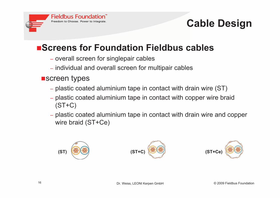
�Screens for Foundation Fieldbus cables– overall screen for singlepair cables– individual and overall screen for multipair cables
�screen types– plastic coated aluminium tape in contact with drain wire (ST)– plastic coated aluminium tape in contact with copper wire braid
(ST+C)– plastic coated aluminium tape in contact with drain wire and copper
wire braid (ST+Ce)
(ST) (ST+C) (ST+Ce)
Cable Design

17 © 2009 Fieldbus FoundationDr. Weiss, LEONI Kerpen GmbH
�Armour types�copolymer coated, corrugated, overlapped steel tape
(SR)�round steel wire armour (SWA)�steel wire braid (Q)
(SR) SWA Q
Cable Design

18 © 2009 Fieldbus FoundationDr. Weiss, LEONI Kerpen GmbH
�Extended chemical protection�special oil resistant PVC, Yö�multi layer sheath, (L)2Y4Y, “ALNYC*)” sheath
– a multilayer sheath can replace a lead sheath.This function is achieved as combination of several layers.
– inner layer of plastic coated aluminium tape (L)– inner sheath of polyethylene (2Y)– outer sheath of polyamide (4Y)
*) ALNYC:AL Aluminium tape, polyethylene laminatedNYC Sheath of polyamide, Nylon Coating
�lead sheath (M)– layer of lead– cover (sheath) of plastic
Cable Design

19 © 2009 Fieldbus FoundationDr. Weiss, LEONI Kerpen GmbH
�Sheath materials�polyvinyl chloride (PVC)
– is the most common material– flame retardent, but– emits corrosive and poisonous gases in case of fire
�low smoke, zero halogen, flame retardent compound (LSZH)– for extended safety in case of fire– low smoke emission, no corrosive or poisonous gases in case of fire– for protection of human life and material assets
�high temperature applications– perfluoroethylene propylene copolymer (FEP)– perfluoro alkoxyalkane (PFA)
�other materials– to be selected based on application
Cable Design
20 © 2009 Fieldbus FoundationDr. Weiss, LEONI Kerpen GmbH
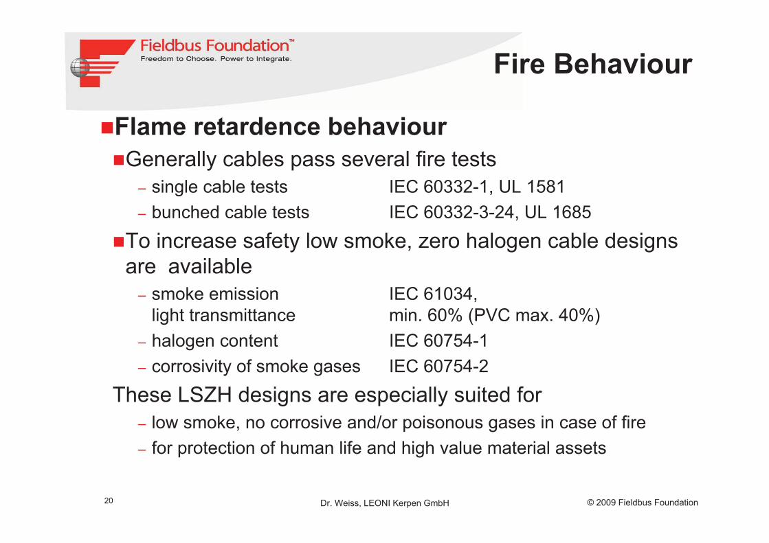
�Flame retardence behaviour�Generally cables pass several fire tests
– single cable tests IEC 60332-1, UL 1581– bunched cable tests IEC 60332-3-24, UL 1685
�To increase safety low smoke, zero halogen cable designs are available
– smoke emission IEC 61034,light transmittance min. 60% (PVC max. 40%)
– halogen content IEC 60754-1– corrosivity of smoke gases IEC 60754-2
These LSZH designs are especially suited for– low smoke, no corrosive and/or poisonous gases in case of fire– for protection of human life and high value material assets
Fire Behaviour

21 © 2009 Fieldbus FoundationDr. Weiss, LEONI Kerpen GmbH
�Fast Assembly (FA)�For quick and easy installation�Using special stripping tool�Cable design with extruded inner sheath
and without drain wire
stripping tool resultcable stripping
Fast Assembly

22 © 2009 Fieldbus FoundationDr. Weiss, LEONI Kerpen GmbH
�FOUNDATION Fieldbus FF (H1) spur and trunk cables, single pair (excerpt)�fixed installation indoor and outdoor, on racks,
in conduits
�suitable for fast assembly
�flexible installation indoor and outdoor, on racks, in conduits
�fixed installation indoor and outdoor, on racks, in conduits. For direct burial
Cables

23 © 2009 Fieldbus FoundationDr. Weiss, LEONI Kerpen GmbH
�FOUNDATION Fieldbus FF (H1) spur and trunkcables, multi pair (excerpt)�in addition to single pair designs multi pair versions are
available�electrical properties of each pair are like in single pair
cable�installation area like single pair designs
Fast Assembly armouredfor direct burial
flexibleinstallation
fixedinstallation
Cables

24 © 2009 Fieldbus FoundationDr. Weiss, LEONI Kerpen GmbH
�Foundation Fieldbus by LEONI Kerpen GmbH�FF-844 H1�IEC 61158-2, type A�EN 50288-7 or UL13/UL2250�ISA S50.02-1992 (physical layer standard) for FF
Fieldbus�Multipair cables with “Type A” properties�Foundation Fieldbus cables with UL-approval�Different armour types�Cables with chemical protection�High temperature versions�Tailor made solutions
Conclusion

25 © 2009 Fieldbus FoundationDr. Weiss, LEONI Kerpen GmbH
Conclusion
�Foundation Fieldbus cable specification�provides a very good frame for design and properties of
fieldbus cables�is focussed on high quality products�refers to designs based on common standards
�Further improvements�conductor to be selected based on application (copper;
plain, tinned, silver- or nickel plated)�temperature range (min. requirements) -30°C to +70°C
– include foamskin PE as best insulation material in terms of electrical properties
�generally refer to IEC 61158-2, type A for electrical properties

26 © 2009 Fieldbus FoundationDr. Weiss, LEONI Kerpen GmbH
�What is the dedication of the Foundation Fieldbus cable specification�set a common standard for high quality fieldbus cables
– referring to state-of-the-art standards
�cover today´s established fieldbus technologies– ensure use of the best suited materials
�be open for higher level applications like – at high temperatures– more stringent electrical requirements than type “A”
�ensure a standard in accordance with related equipment standards, like for connectors, field devices
�Other topics to ensure– customer related requirements– possible local requirements
Outlook

27 © 2009 Fieldbus FoundationDr. Weiss, LEONI Kerpen GmbH
Thank You for Your Attention