Experiment 9 Three-Phase Induction Motor With … 9.pdf · Experiment 9 Three-Phase Induction Motor...
17
0405344: Electrical Machines for Mechatronics Laboratory 9 – 1 Experiment 9 Three-Phase Induction Motor With Frequency Inverter Objectives • To be familiar with the 3-phase induction motor different configuration. • To control the speed of the motor using a frequency inverter. • To use the frequency inverter to control other parameter of the motor. Introduction The three phase induction motor essentially consists of two parts: stator and rotor. The stator is always connected to a three phase power supply. Due to the phase shift of 120° between each successive phases, a rotating magnetic field is produced and governed by the following expression P f n sync 120 = (9.1) Where f is the system frequency, P is the number of poles and sync n is the speed of the magnetic field's rotation. The produced rotating magnetic field passes over the rotor bars and induces a voltage in them and that's why this machine is called an induction motor. There are two different types of induction motor rotors which can be placed inside the stator. One is called a squirrel-cage rotor or simply a cage rotor, while the other is called a wound rotor. The Concept of Rotor Slip The voltage induced in a rotor bar of an induction motor depends on the speed of the rotor relative to the magnetic fields. Since the behavior of an induction motor depends on the rotor's voltage and current, it is often more logical to talk about this relative speed. Two terms are commonly used to define the relative motion of the rotor and the magnetic fields. One of them is slip speed. Slip speed is defined as the difference between synchronous speed and rotor speed: slip sync m n n n = − (9.2) where = slip n slip speed of the motor
Transcript of Experiment 9 Three-Phase Induction Motor With … 9.pdf · Experiment 9 Three-Phase Induction Motor...
0405344: Electrical Machines for Mechatronics Laboratory 9 – 1
Experiment 9 Three-Phase Induction Motor
With Frequency Inverter Objectives • To be familiar with the 3-phase induction motor different configuration. • To control the speed of the motor using a frequency inverter. • To use the frequency inverter to control other parameter of the motor. Introduction The three phase induction motor essentially consists of two parts: stator and rotor. The stator is always connected to a three phase power supply. Due to the phase shift of 120° between each successive phases, a rotating magnetic field is produced and governed by the following expression
P
fnsync120
= (9.1)
Where f is the system frequency, P is the number of poles and syncn is the speed of the magnetic
field's rotation. The produced rotating magnetic field passes over the rotor bars and induces a voltage in them and that's why this machine is called an induction motor. There are two different types of induction motor rotors which can be placed inside the stator. One is called a squirrel-cage rotor or simply a cage rotor, while the other is called a wound rotor.
The Concept of Rotor Slip The voltage induced in a rotor bar of an induction motor depends on the speed of the rotor relative to the magnetic fields. Since the behavior of an induction motor depends on the rotor's voltage and current, it is often more logical to talk about this relative speed. Two terms are commonly used to define the relative motion of the rotor and the magnetic fields. One of them is slip speed. Slip speed is defined as the difference between synchronous speed and rotor speed: slip sync mn n n= − (9.2)
where
=slipn slip speed of the motor
Experiment 9 Three-Phase Induction Motor With Frequency Inverter
0405344: Electrical Machines for Mechatronics Laboratory 9 – 2
=syncn speed of magnetic fields
=mn mechanical shaft speed of rotor The other term used to describe the relative motion is slip. Slip is the relative speed expressed on a per-unit or a percent basis. That is, slip is defined as
%100×=sync
slip
nn
s (9.3)
%100×−
=sync
msync
nnn
s (9.4)
This equation can also be expressed in terms of angular velocity ω (radians per second) as
%100×−
=sync
msyncsω
ωω (9.5)
Notice that, if the rotor turns at synchronous speed, 0=s , while if the rotor is stationary, 1=s . All normal motor speeds fall somewhere between those two limits. Its possible to express the mechanical speed of the rotor shaft in terms of synchronous speed and slip. Solving equations 9.4 and 9.5 for mechanical speed yields syncm nsn )1( −= (9.6)
or syncm s ωω )1( −= (9.7)
These equations are useful in the derivation of induction motor torque and power relationships. The Electrical Frequency on the rotor An induction motor works by inducing voltages and currents in the rotor of the machine, and for that reason has sometimes been called a rotating transformer. Like a transformer, the primary (stator) induces a voltage in the secondary (rotor), but unlike a transformer, the secondary frequency is not necessarily the same as the primary frequency. If the rotor of a motor is locked so that it can not move, then the rotor will have the same frequency as the stator. On the other hand, if the rotor turns at synchronous speed, the frequency on the rotor will be zero. What will the rotor frequency be for any arbitrary rate of rotor rotation? At 0=mn rev/min, the rotor frequency er ff = and the slip 1=s . At syncm nn = , the rotor frequency
0=rf Hz and the slip 0=s . For any speed in between,
Experiment 9 Three-Phase Induction Motor With Frequency Inverter
0405344: Electrical Machines for Mechatronics Laboratory 9 – 3
er sff = (9.8) Several alternative forms of this expression exist that are sometimes useful. One of the more common expressions is derived by substituting 9.4 for the slip into 9.8 and then substituting for syncn in the
denominator of the expression:
esync
msyncr f
nnn
f−
= (9.9)
But P
fnsync120
= from Equation 9.1, so
ee
msyncr ff
Pnnf120
)( −= (9.10)
therefore
)(120 msyncr nnPf −= (9.11)
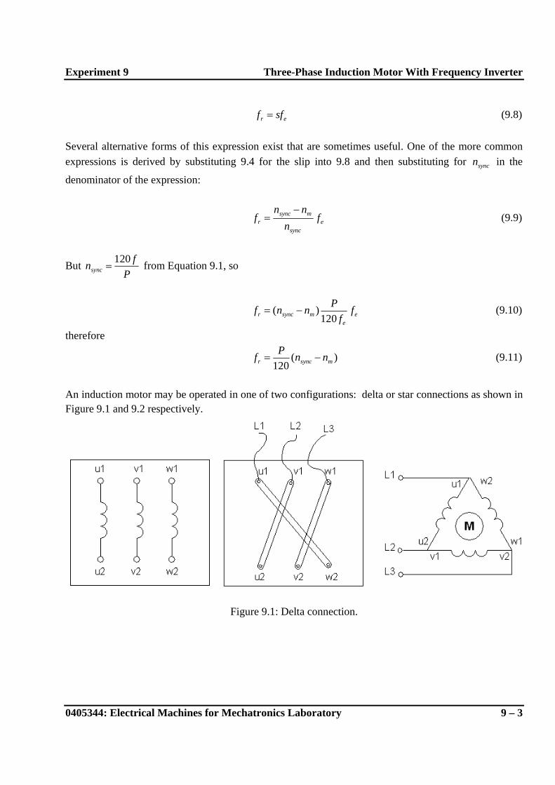
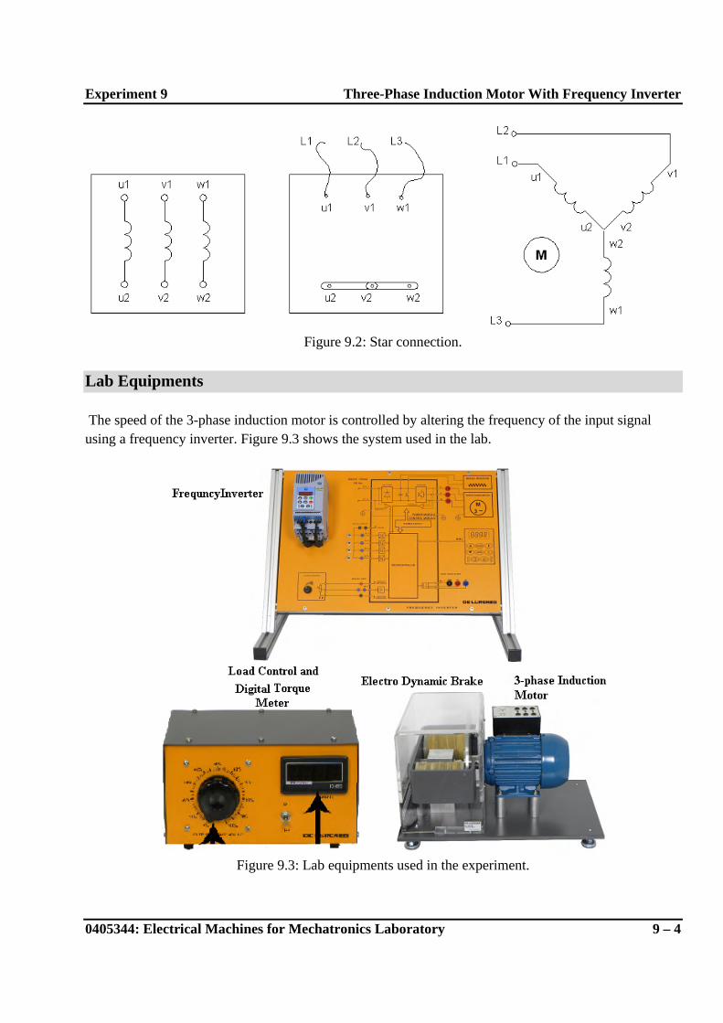
An induction motor may be operated in one of two configurations: delta or star connections as shown in Figure 9.1 and 9.2 respectively.
Figure 9.1: Delta connection.
Experiment 9 Three-Phase Induction Motor With Frequency Inverter
0405344: Electrical Machines for Mechatronics Laboratory 9 – 4
Figure 9.2: Star connection.
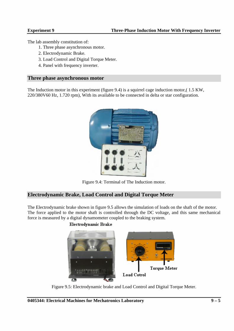
Lab Equipments The speed of the 3-phase induction motor is controlled by altering the frequency of the input signal using a frequency inverter. Figure 9.3 shows the system used in the lab.
Figure 9.3: Lab equipments used in the experiment.
Experiment 9 Three-Phase Induction Motor With Frequency Inverter
0405344: Electrical Machines for Mechatronics Laboratory 9 – 5
The lab assembly constitution of: 1. Three phase asynchronous motor. 2. Electrodynamic Brake. 3. Load Control and Digital Torque Meter. 4. Panel with frequency inverter.
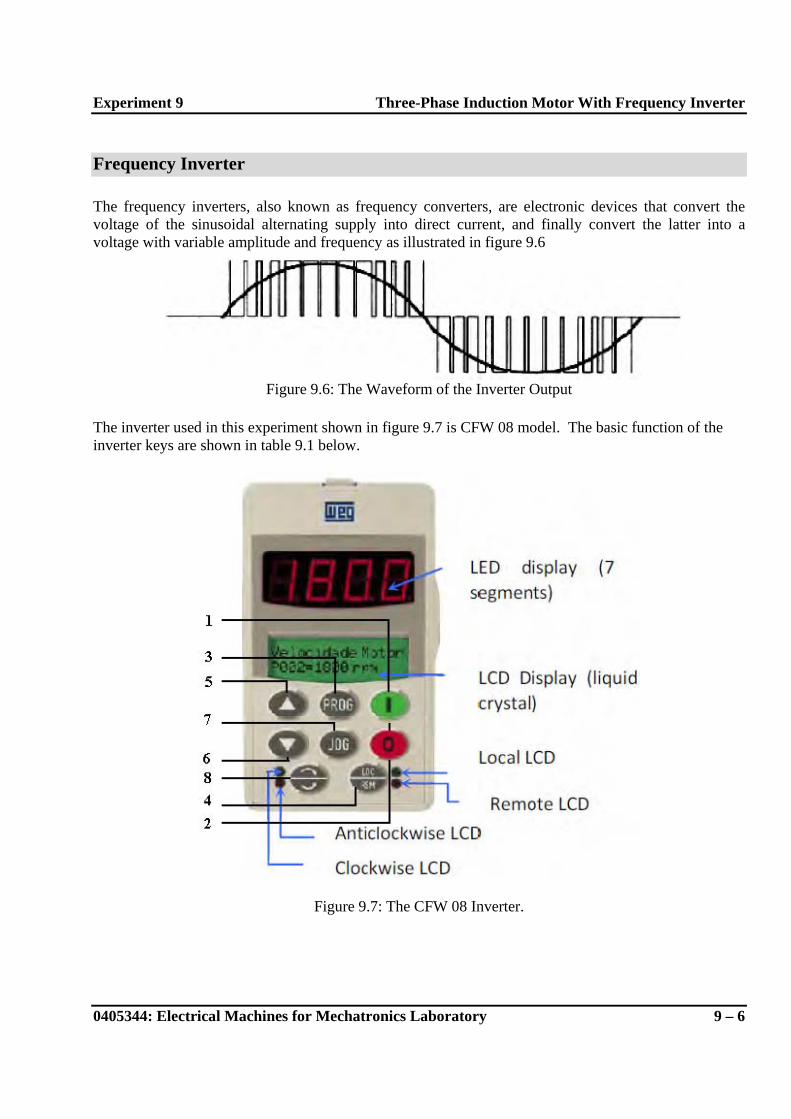
Three phase asynchronous motor The Induction motor in this experiment (figure 9.4) is a squirrel cage induction motor,( 1.5 KW, 220/380V60 Hz, 1.720 rpm), With its available to be connected in delta or star configuration.
Figure 9.4: Terminal of The Induction motor.
Electrodynamic Brake, Load Control and Digital Torque Meter The Electrodynamic brake shown in figure 9.5 allows the simulation of loads on the shaft of the motor. The force applied to the motor shaft is controlled through the DC voltage, and this same mechanical force is measured by a digital dynamometer coupled to the braking system.
Figure 9.5: Electrodynamic brake and Load Control and Digital Torque Meter.
Experiment 9 Three-Phase Induction Motor With Frequency Inverter
0405344: Electrical Machines for Mechatronics Laboratory 9 – 6
Frequency Inverter The frequency inverters, also known as frequency converters, are electronic devices that convert the voltage of the sinusoidal alternating supply into direct current, and finally convert the latter into a voltage with variable amplitude and frequency as illustrated in figure 9.6
Figure 9.6: The Waveform of the Inverter Output
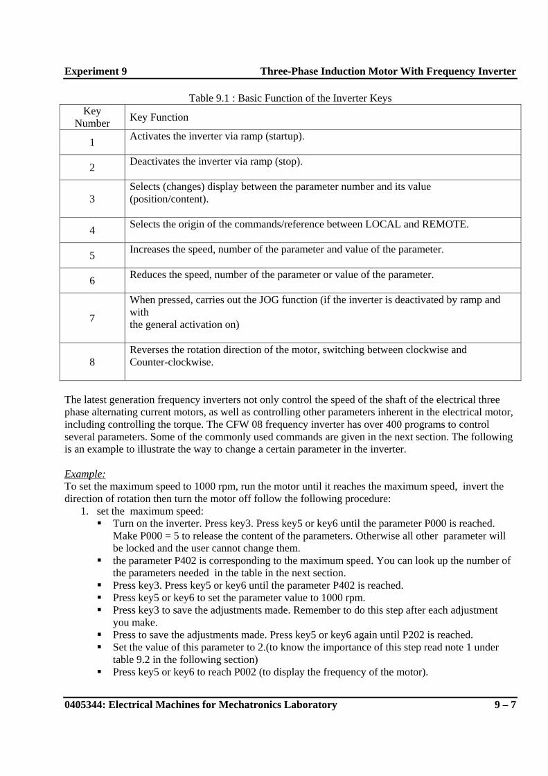
The inverter used in this experiment shown in figure 9.7 is CFW 08 model. The basic function of the inverter keys are shown in table 9.1 below.
Figure 9.7: The CFW 08 Inverter.
Experiment 9 Three-Phase Induction Motor With Frequency Inverter
0405344: Electrical Machines for Mechatronics Laboratory 9 – 7
Table 9.1 : Basic Function of the Inverter Keys Key
Number Key Function
1 Activates the inverter via ramp (startup).
2 Deactivates the inverter via ramp (stop).
3 Selects (changes) display between the parameter number and its value (position/content).
4 Selects the origin of the commands/reference between LOCAL and REMOTE.
5 Increases the speed, number of the parameter and value of the parameter.
6 Reduces the speed, number of the parameter or value of the parameter.
7
When pressed, carries out the JOG function (if the inverter is deactivated by ramp and with the general activation on)
8 Reverses the rotation direction of the motor, switching between clockwise and Counter-clockwise.
The latest generation frequency inverters not only control the speed of the shaft of the electrical three phase alternating current motors, as well as controlling other parameters inherent in the electrical motor, including controlling the torque. The CFW 08 frequency inverter has over 400 programs to control several parameters. Some of the commonly used commands are given in the next section. The following is an example to illustrate the way to change a certain parameter in the inverter. Example: To set the maximum speed to 1000 rpm, run the motor until it reaches the maximum speed, invert the direction of rotation then turn the motor off follow the following procedure:
1. set the maximum speed: Turn on the inverter. Press key3. Press key5 or key6 until the parameter P000 is reached.
Make P000 = 5 to release the content of the parameters. Otherwise all other parameter will be locked and the user cannot change them.
the parameter P402 is corresponding to the maximum speed. You can look up the number of the parameters needed in the table in the next section.
Press key3. Press key5 or key6 until the parameter P402 is reached. Press key5 or key6 to set the parameter value to 1000 rpm. Press key3 to save the adjustments made. Remember to do this step after each adjustment
you make. Press to save the adjustments made. Press key5 or key6 again until P202 is reached. Set the value of this parameter to 2.(to know the importance of this step read note 1 under
table 9.2 in the following section) Press key5 or key6 to reach P002 (to display the frequency of the motor).
Experiment 9 Three-Phase Induction Motor With Frequency Inverter
0405344: Electrical Machines for Mechatronics Laboratory 9 – 8
2. Turn the motor on: Press key1 (the motor should accelerate from 0 to 90 rpm in the clockwise direction) Press key5 and hold it until the motor reaches 1000rpm. Note that the speed will not
increase over 1000rpm even if you tried to increased by pressing key5.
3. Invert the direction of rotation: Press key8 (the motor decelerates until the motor decelerates to zero rotations and starts
to accelerate in the counter-clockwise direction up to 1000rpm).
4. Turn the motor off: Press key2 (the motor decelerates again to 0 rpm).
5. The jog function
Press key7 and observe the motor behavior. Press key7 again. To understand the last two steps refer to P122.
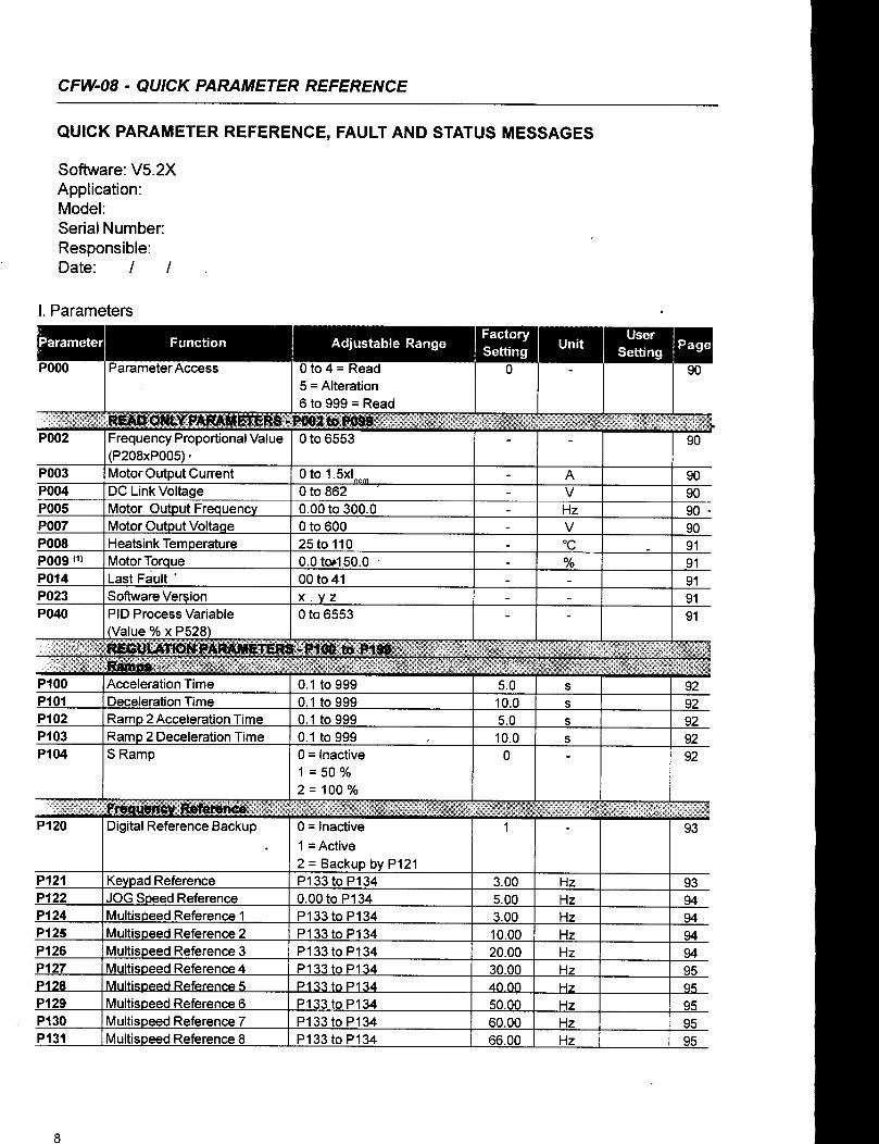
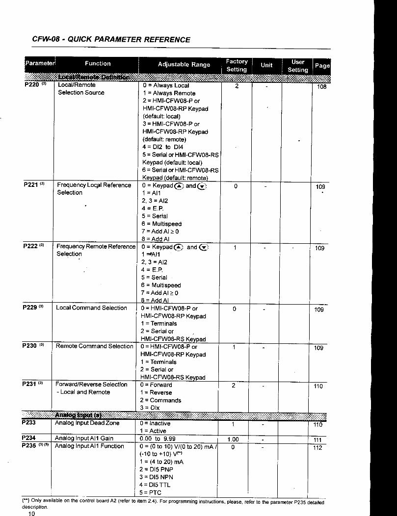
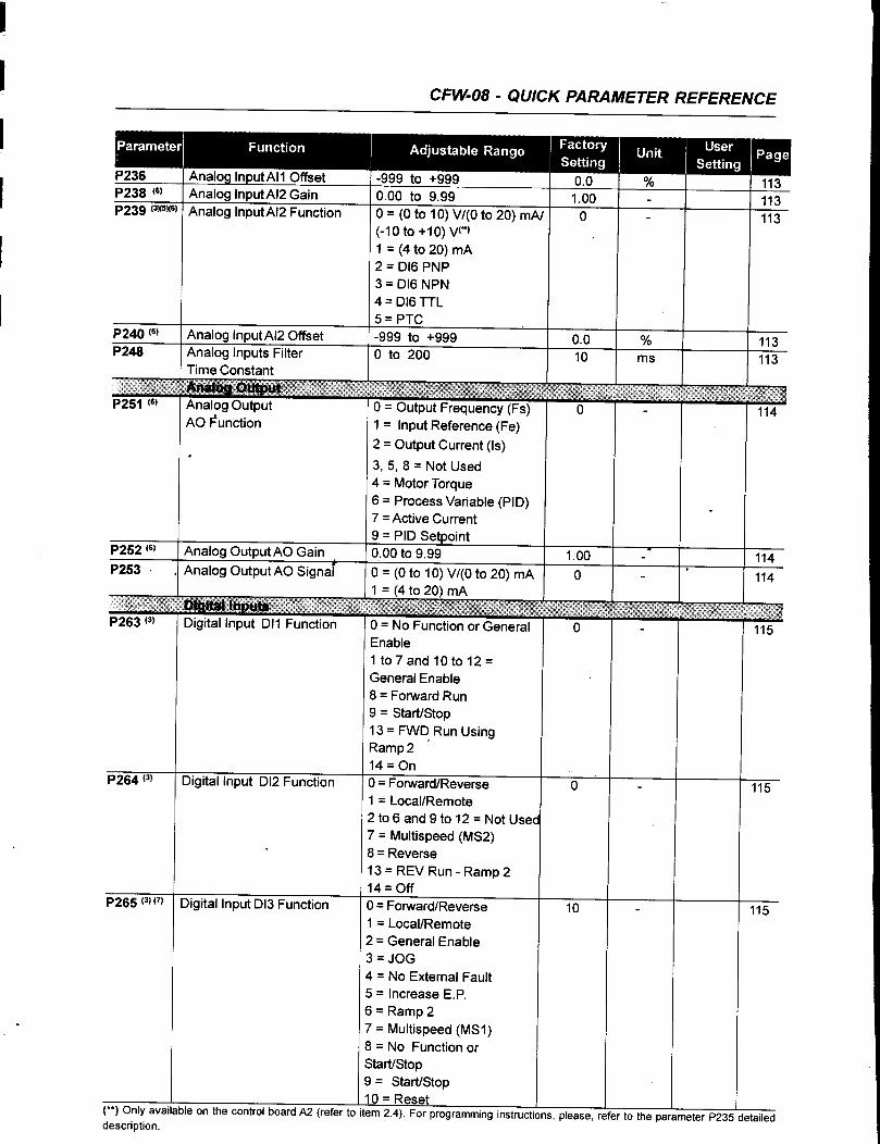
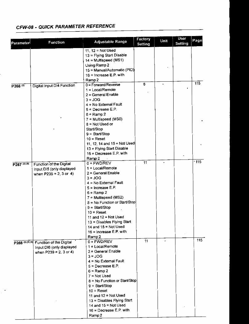
Frequency Inverter Parameters