Three phase induction motor - Educypedia
75
Induction Motor
Transcript of Three phase induction motor - Educypedia

Induction Motor
Induction Motors
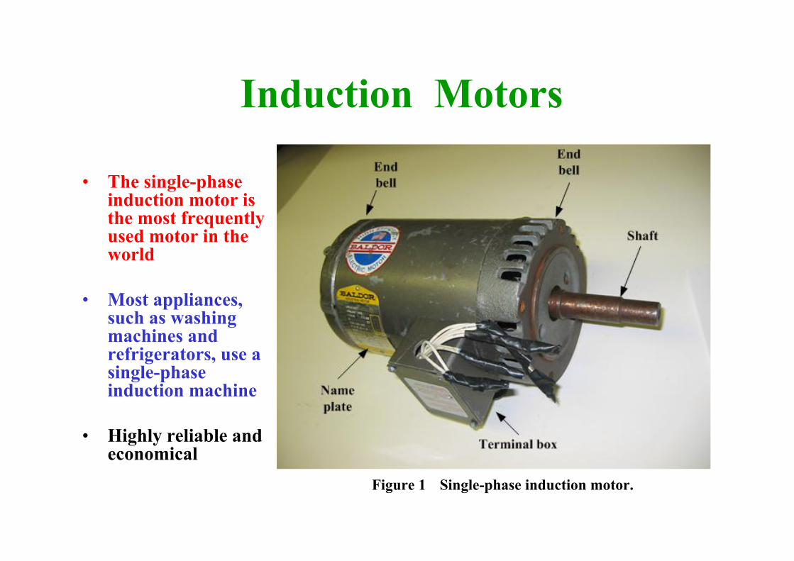
• The single-phase induction motor is the most frequently used motor in the world
• Most appliances, such as washing machines and refrigerators, use a single-phase induction machine
• Highly reliable and economical
Figure 1 Single-phase induction motor.
Induction Motors
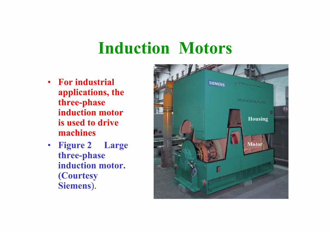
• For industrial applications, the three-phase induction motor is used to drive machines
• Figure 2 Large three-phase induction motor. (Courtesy Siemens).
Housing
Motor
Induction Motors
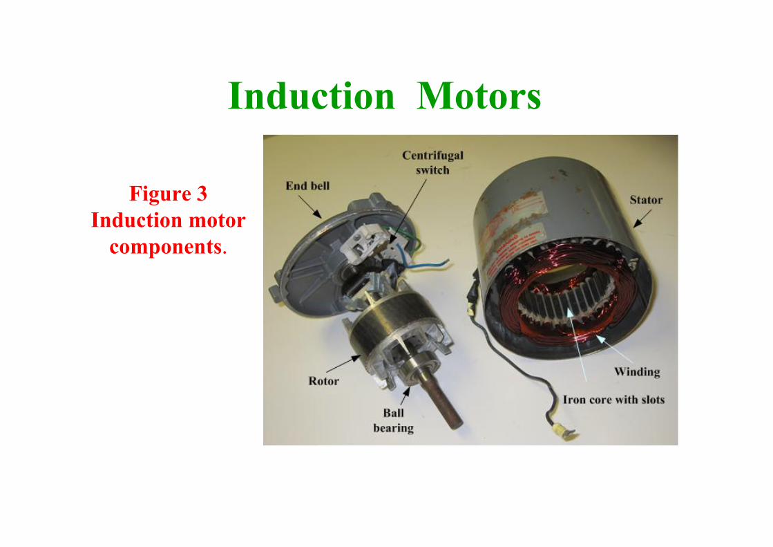
Figure 3Induction motor
components.

Induction Motors• The motor housing consists of three parts:
– The cylindrical middle piece that holds the stator iron core,
– The two bell-shaped end covers holding the ball bearings.
– This motor housing is made of cast aluminum or cast iron. Long screws hold the three parts together.
– The legs at the middle section permit the attachment of the motor to a base.
– A cooling fan is attached to the shaft at the left-hand side. This fan blows air over the ribbed stator frame.
Induction Motors
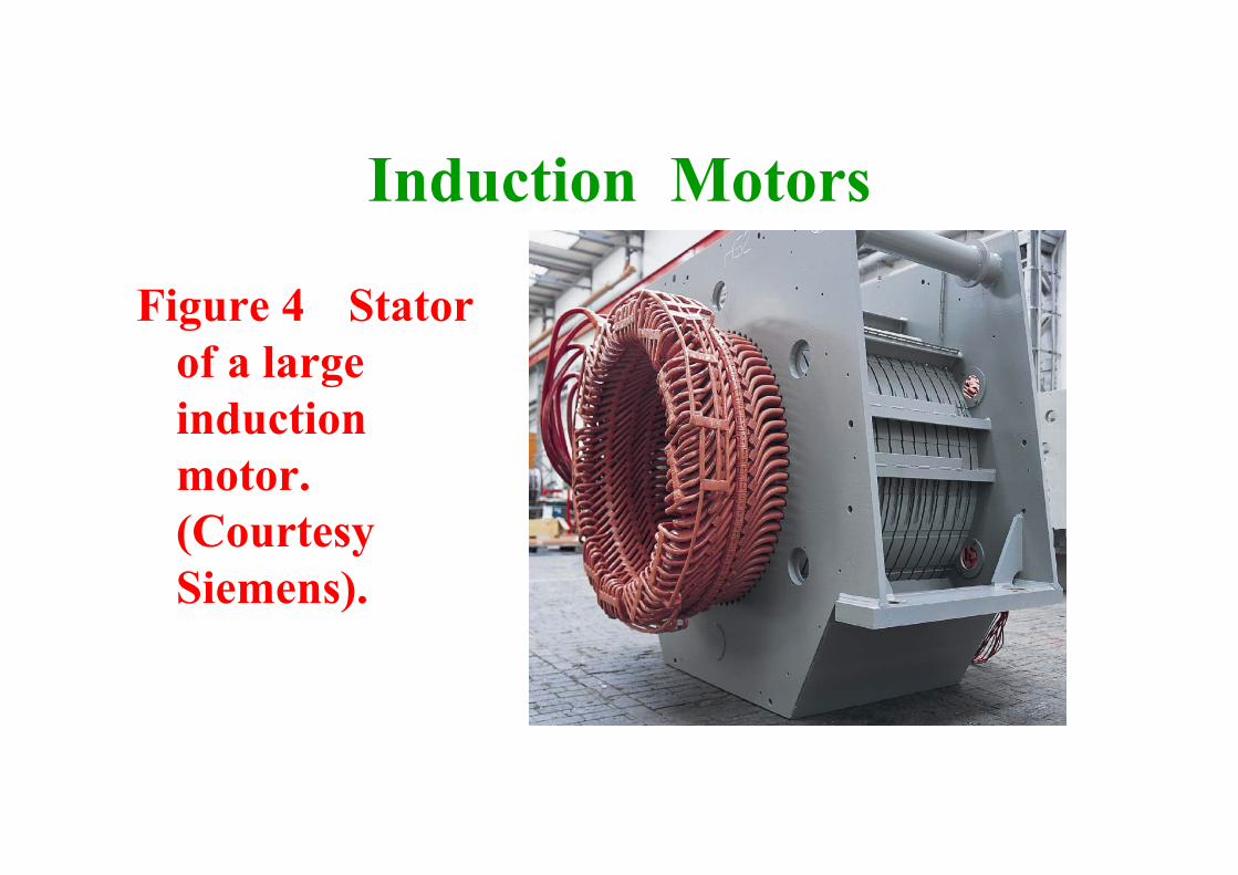
Figure 4 Stator of a large induction motor. (Courtesy Siemens).
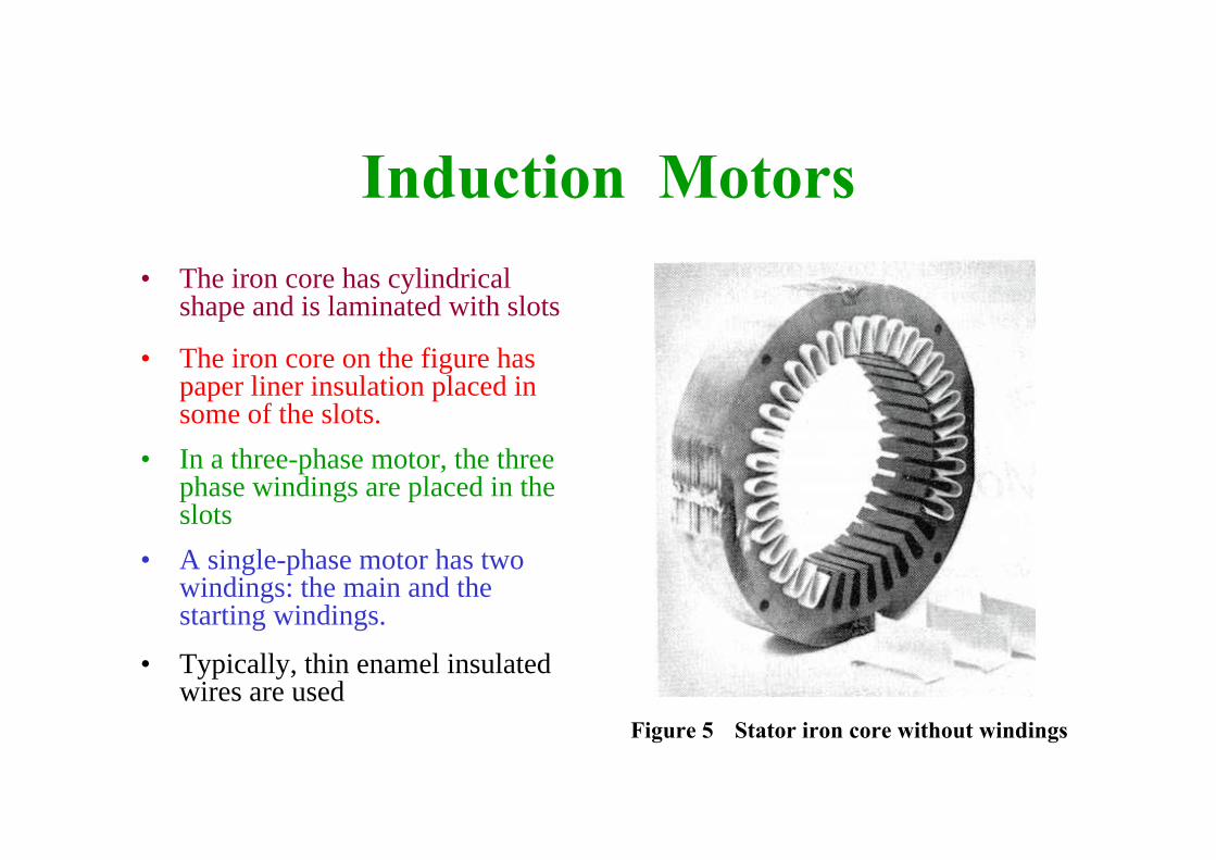
Induction Motors• The iron core has cylindrical
shape and is laminated with slots
• The iron core on the figure has paper liner insulation placed in some of the slots.
• In a three-phase motor, the three phase windings are placed in the slots
• A single-phase motor has two windings: the main and the starting windings.
• Typically, thin enamel insulated wires are used
Figure 5 Stator iron core without windings
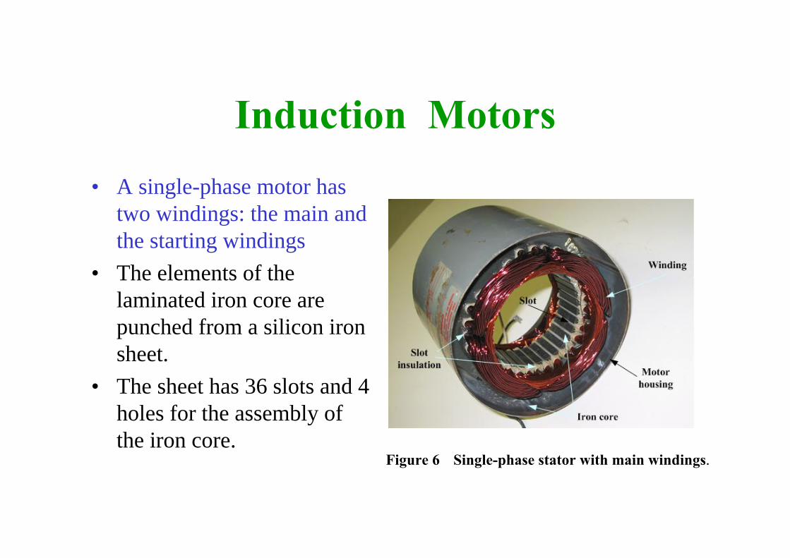
Induction Motors• A single-phase motor has
two windings: the main and the starting windings
• The elements of the laminated iron core are punched from a silicon iron sheet.
• The sheet has 36 slots and 4 holes for the assembly of the iron core.
Figure 6 Single-phase stator with main windings.
Induction Motors
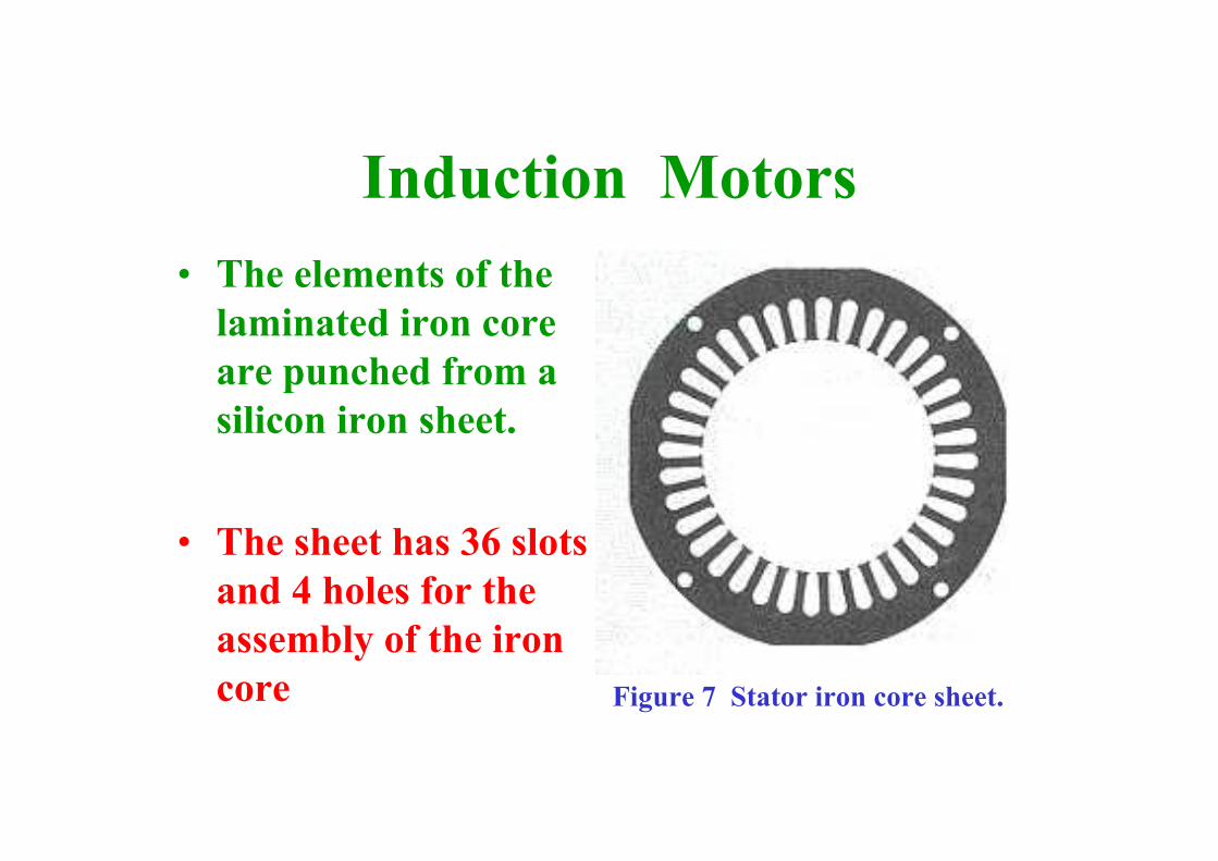
Figure 7 Stator iron core sheet.
• The elements of the laminated iron core are punched from a silicon iron sheet.
• The sheet has 36 slots and 4 holes for the assembly of the iron core
Induction Motors
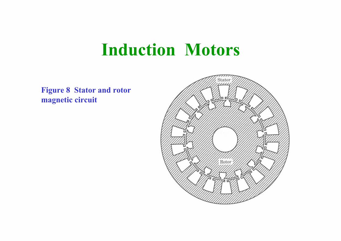
Figure 8 Stator and rotor magnetic circuit
Induction Motors
Squirrel cage rotor. • This rotor has a laminated iron core with slots,
and is mounted on a shaft.• Aluminum bars are molded in the slots and the
bars are short circuited with two end rings. • The bars are slanted on a small rotor to reduce
audible noise. • Fins are placed on the ring that shorts the
bars. These fins work as a fan and improve cooling.
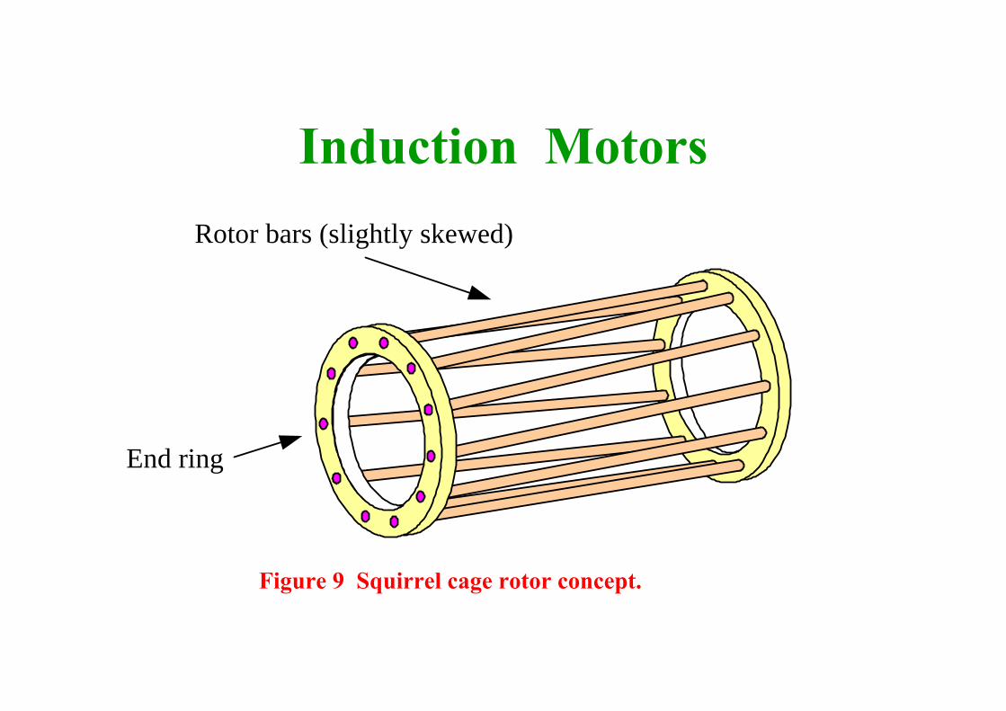
Induction MotorsRotor bars (slightly skewed)
End ring
Figure 9 Squirrel cage rotor concept.
Induction Motors
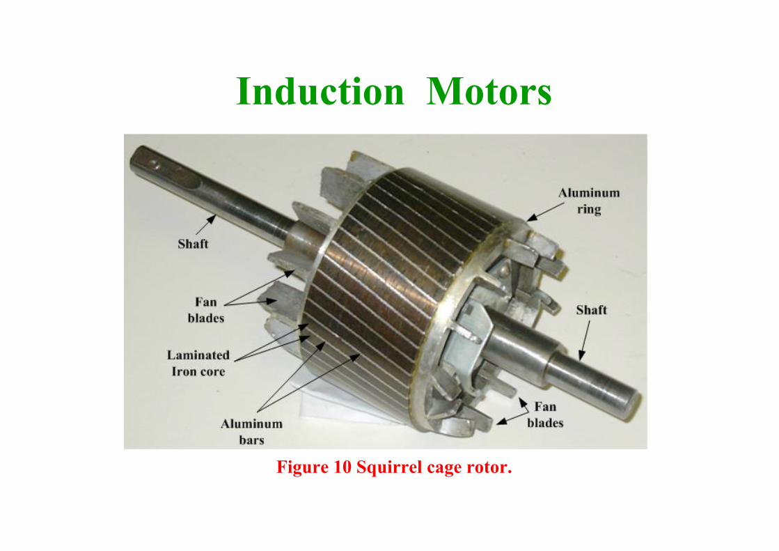
Figure 10 Squirrel cage rotor.
Induction MotorsWound rotor. • Most motors use the squirrel-cage rotor because of the
robust and maintenance-free construction.• However, large, older motors use a wound rotor with
three phase windings placed in the rotor slots.• The windings are connected in a three-wire wye.• The ends of the windings are connected to three slip rings. • Resistors or power supplies are connected to the slip rings
through brushes for reduction of starting current and speed control
Induction Motors
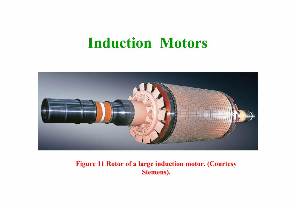
Figure 11 Rotor of a large induction motor. (Courtesy Siemens).

Operating principle
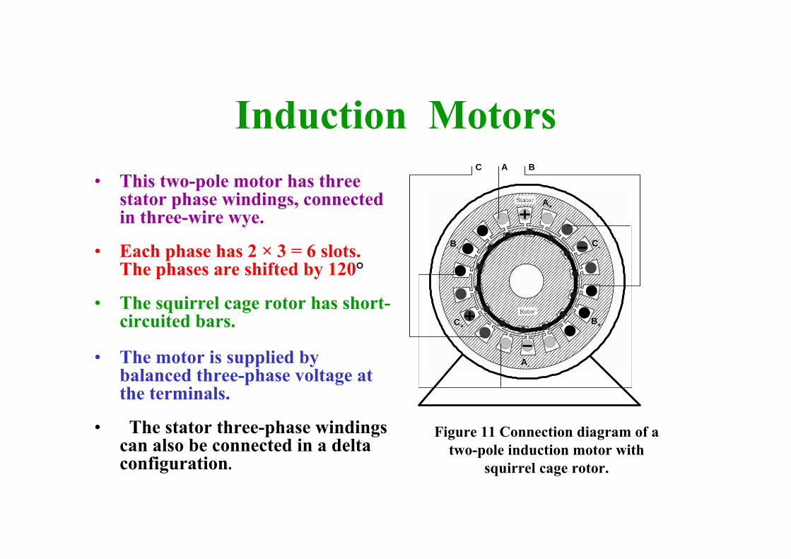
Induction Motors• This two-pole motor has three
stator phase windings, connected in three-wire wye.
• Each phase has 2 × 3 = 6 slots. The phases are shifted by 120°
• The squirrel cage rotor has short-circuited bars.
• The motor is supplied by balanced three-phase voltage at the terminals.
• The stator three-phase windings can also be connected in a delta configuration.
A+
A-
B+
B-
C+
C-
A BC
Figure 11 Connection diagram of a two-pole induction motor with
squirrel cage rotor.
Induction Motors
Operation Principle• The three-phase stator is supplied by balanced three-
phase voltage that drives an ac magnetizing current through each phase winding.
• The magnetizing current in each phase generates a pulsating ac flux.
• The flux amplitude varies sinusoidally and the direction of the flux is perpendicular to the phase winding.
Induction Motors
Operation Principle• The three-phase stator is supplied by balanced three-
phase voltage that drives an ac magnetizing current through each phase winding.
• The magnetizing current in each phase generates a pulsating ac flux.
• The total flux in the machine is the sum of the three fluxes.
• The summation of the three ac fluxes results in a rotating flux, which turns with constant speed and has constant amplitude.
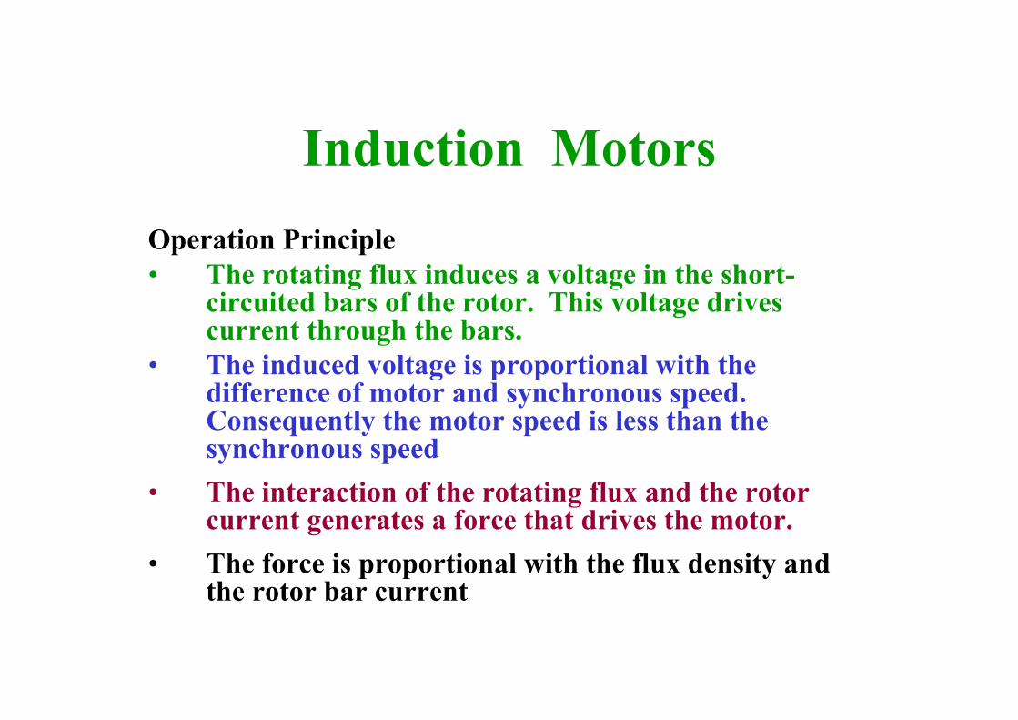
Induction MotorsOperation Principle• The rotating flux induces a voltage in the short-
circuited bars of the rotor. This voltage drives current through the bars.
• The induced voltage is proportional with the difference of motor and synchronous speed. Consequently the motor speed is less than the synchronous speed
• The interaction of the rotating flux and the rotor current generates a force that drives the motor.
• The force is proportional with the flux density and the rotor bar current
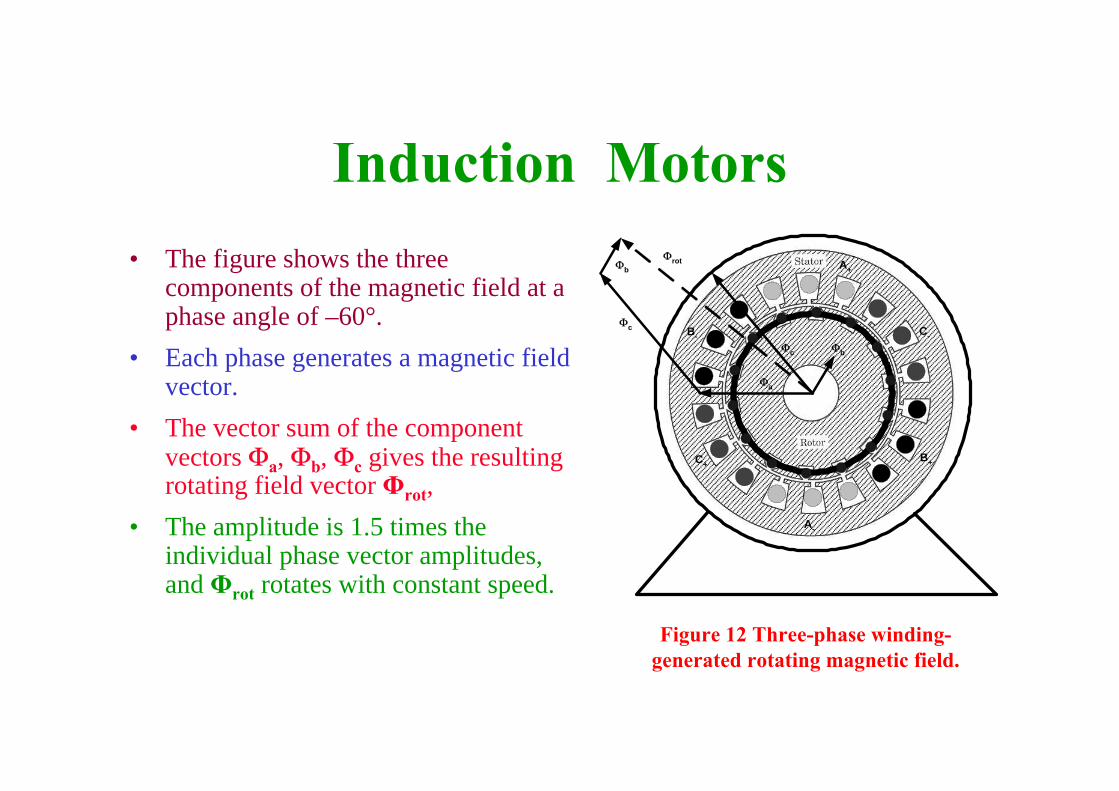
Induction Motors• The figure shows the three
components of the magnetic field at a phase angle of –60°.
• Each phase generates a magnetic field vector.
• The vector sum of the component vectors Φa, Φb, Φc gives the resulting rotating field vector Φrot,
• The amplitude is 1.5 times the individual phase vector amplitudes, and Φrot rotates with constant speed.
A+
A-
B+
B-
C+
C-
Φb
Φa
Φrot
Φc
Φb
Φc
Figure 12 Three-phase winding-generated rotating magnetic field.

Induced Voltage Generation
Induction Motors
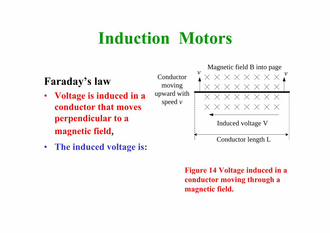
Faraday’s law• Voltage is induced in a
conductor that moves perpendicular to a magnetic field,
• The induced voltage is:
Magnetic field B into pageConductor
movingupward with
speed v
Induced voltage V
Conductor length L
v v
Figure 14 Voltage induced in a conductor moving through a magnetic field.

Induction Motors• The three-phase winding on
the stator generates a rotating field.
• The rotor bar cuts the magnetic field lines as the field rotates.
• The rotating field induces a voltage in the short-circuited rotor bars
• The induced voltage is proportional to the speed difference between the rotating field and the spinning rotor
A+
A-
B+
B-
C+
C-
Φb
Φa
Φrot
Φc
Φb
Φc
V = B L (vsyn – v m)
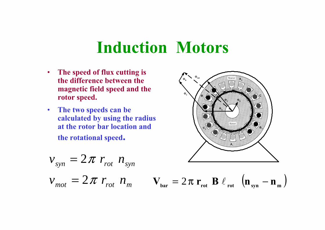
Induction Motors• The speed of flux cutting is
the difference between the magnetic field speed and the rotor speed.
• The two speeds can be calculated by using the radius at the rotor bar location and the rotational speed.
A+
A-
B+
B-
C+
C-
Φb
Φa
Φrot
Φc
Φb
Φc
mrotmot
synrotsyn
nrvnrv
ππ
2
2
=
=
( )msynrotrotbar nnBrV −π= l2
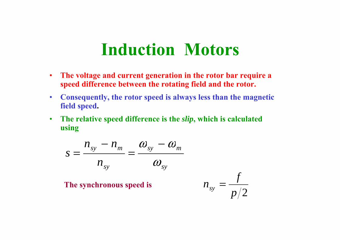
Induction Motors• The voltage and current generation in the rotor bar require a
speed difference between the rotating field and the rotor.• Consequently, the rotor speed is always less than the magnetic
field speed. • The relative speed difference is the slip, which is calculated
using
sy
msy
sy
msy
nnn
sω
ωω −=
−=
2pfnsy =The synchronous speed is

Motor Force Generation
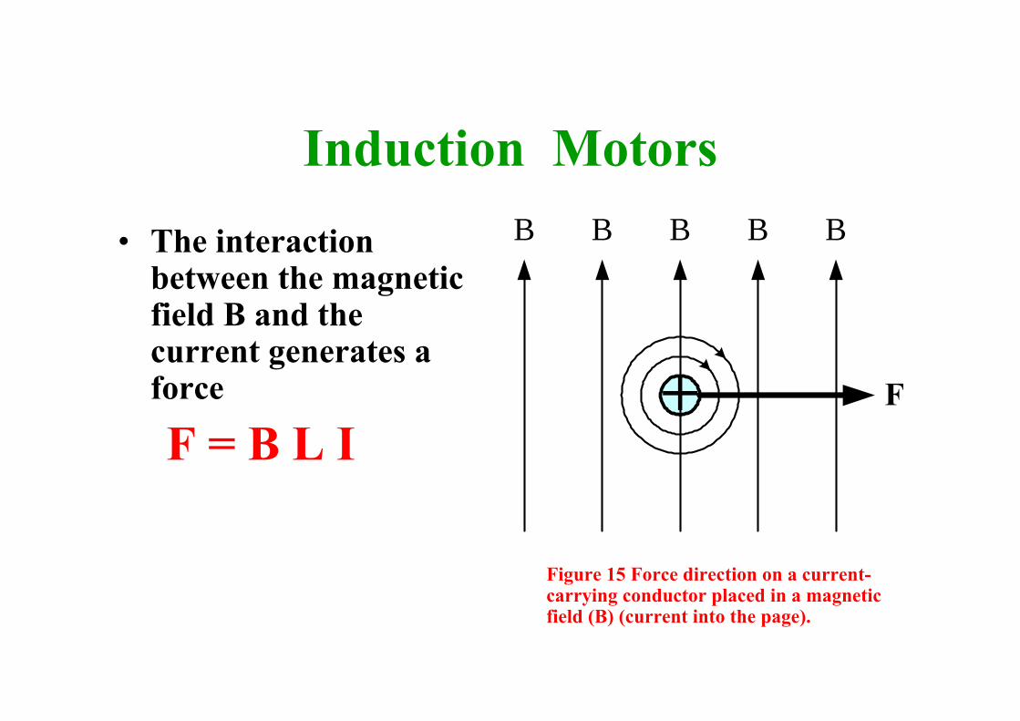
Induction Motors• The interaction
between the magnetic field B and the current generates a force
F = B L I+
B B B B
F
B
Figure 15 Force direction on a current-carrying conductor placed in a magnetic field (B) (current into the page).
Induction Motors
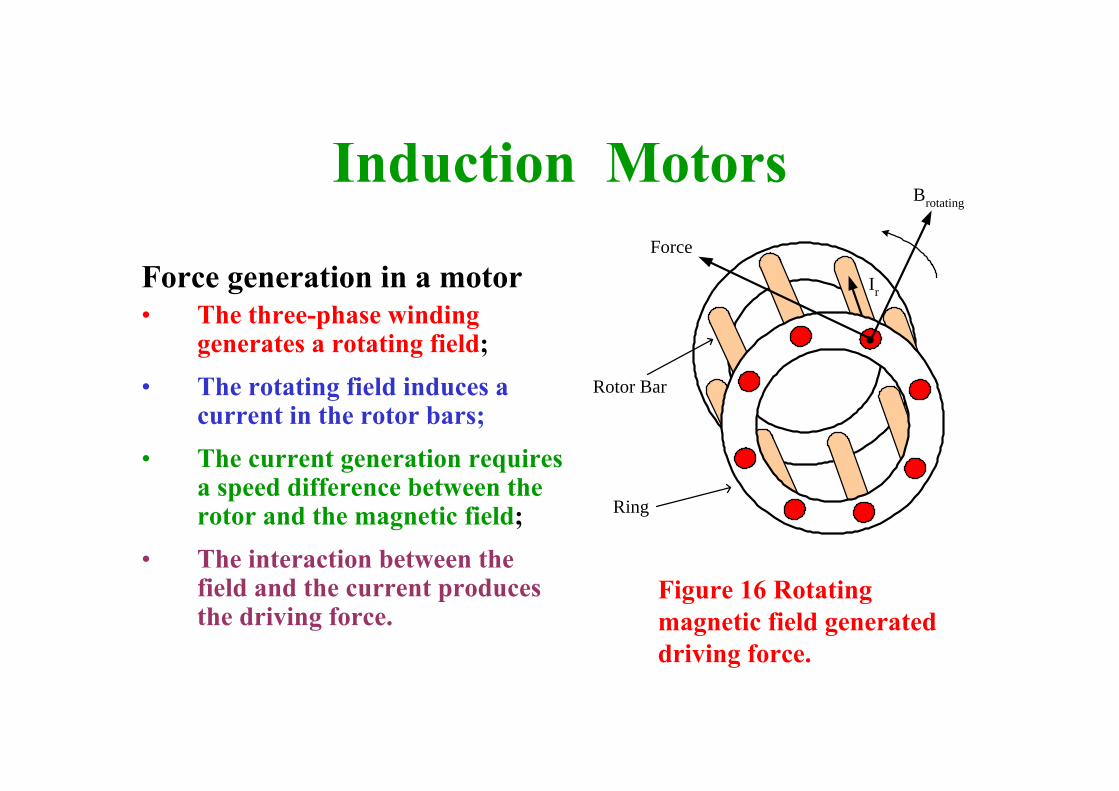
Force generation in a motor• The three-phase winding
generates a rotating field;• The rotating field induces a
current in the rotor bars;• The current generation requires
a speed difference between the rotor and the magnetic field;
• The interaction between the field and the current produces the driving force.
Brotating
Force
Ir
Rotor Bar
Ring
Figure 16 Rotating magnetic field generated driving force.
Equivalent circuit
Induction Motors• An induction motor has two magnetically coupled circuits:
the stator and the rotor. The latter is short-circuited.
• This is similar to a transformer, whose secondary is rotating and short-circuited.
• The motor has balanced three-phase circuits; consequently, the single-phase representation is sufficient.
• Both the stator and rotor have windings, which have resistance and leakage inductance.
• The stator and rotor winding are represented by a resistance and leakage reactance connected in series

Induction Motors• A transformer represents the magnetic coupling
between the two circuits.
• The stator produces a rotating magnetic field that induces voltage in both windings.– A magnetizing reactance (Xm) and a resistance connected in
parallel represent the magnetic field generation.
– The resistance (Rc) represents the eddy current and hysteresislosses in the iron core
• The induced voltage is depend on the slip and the turn ratio
Induction Motors
Stator Rotor
Xrot_m = ωrot Lrot Rrot
Irot
Vrot = s Vrot_s
Rsta Irot_t
VstaVsupIsta XmRc
Xsta = ωsy Lsta
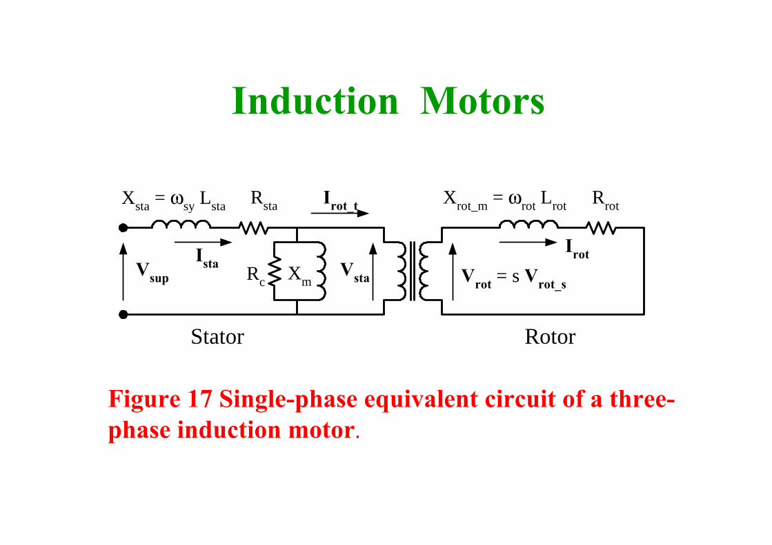
Figure 17 Single-phase equivalent circuit of a three-phase induction motor.
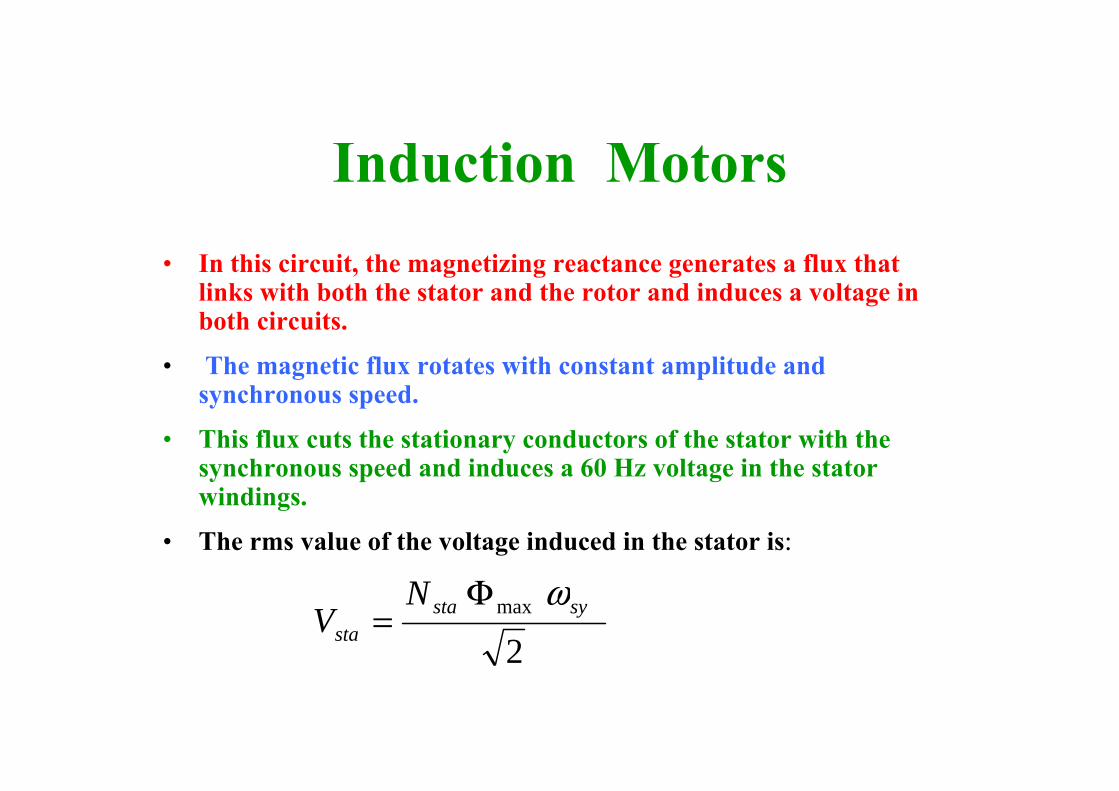
Induction Motors• In this circuit, the magnetizing reactance generates a flux that
links with both the stator and the rotor and induces a voltage in both circuits.
• The magnetic flux rotates with constant amplitude and synchronous speed.
• This flux cuts the stationary conductors of the stator with the synchronous speed and induces a 60 Hz voltage in the stator windings.
• The rms value of the voltage induced in the stator is:
2max systa
sta
NV
ωΦ=

Induction Motors• The flux rotates with the synchronous speed and the rotor
with the motor speed.
• Consequently, the flux cuts the rotor conductors with the speed difference between the rotating flux and the rotor.
• The speed difference is calculated using the slip equation:
• The induced voltage is:
ssymsy ωωω =− )(
22
)( maxmax sNNV syrotmsyrot
rot
ωωω Φ=
−Φ=

Induction Motors• The division of the rotor and stator induced voltage
results in:
• This speed difference determines the frequency of the rotor current
• The rotor circuit leakage reactance is:
sVsVNNV srotsta
sta
rotrot _==
sysymsyrot
rot fss
f ==−
==π
ωπ
ωωπ
ω222
sXsLLX rotsyrotrotrotmrot === ωω_
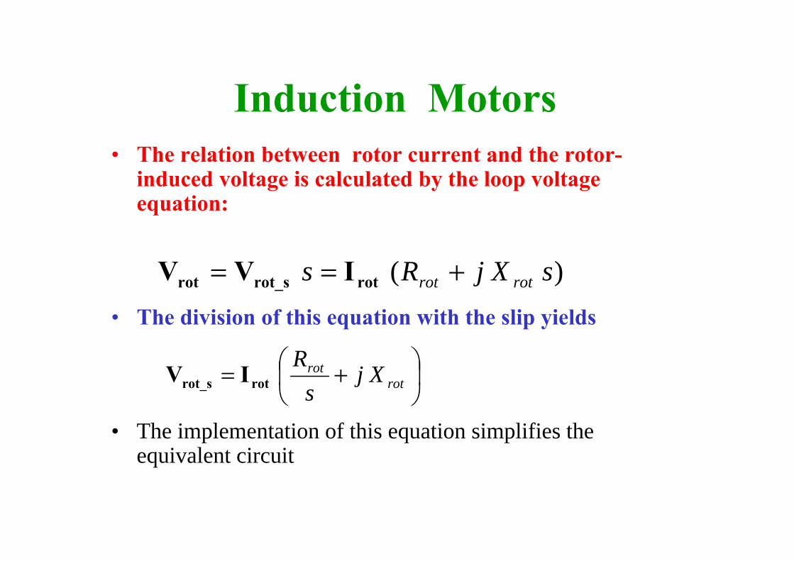
Induction Motors• The relation between rotor current and the rotor-
induced voltage is calculated by the loop voltage equation:
• The division of this equation with the slip yields
• The implementation of this equation simplifies the equivalent circuit
)( sXjRs rotrot +== rotrot_srot IVV
⎟⎠⎞
⎜⎝⎛ += rot
rot Xjs
Rrotrot_s IV
Induction Motors
Stator Rotor
Xsta Xrot Rrot/s
IrotVrot_s
Rsta Irot_t
VstaVsupIsta XmRc
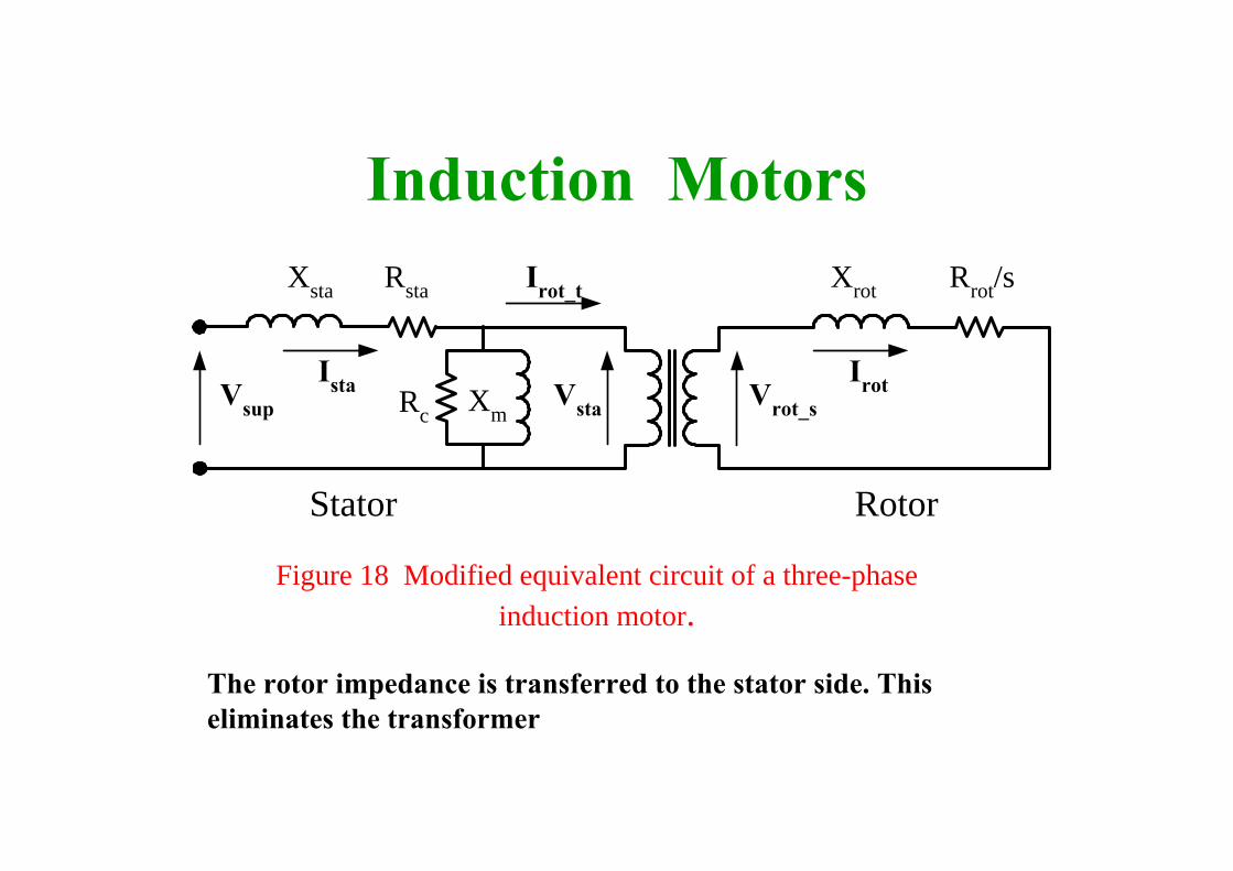
Figure 18 Modified equivalent circuit of a three-phase induction motor.
The rotor impedance is transferred to the stator side. This eliminates the transformer
Induction Motors
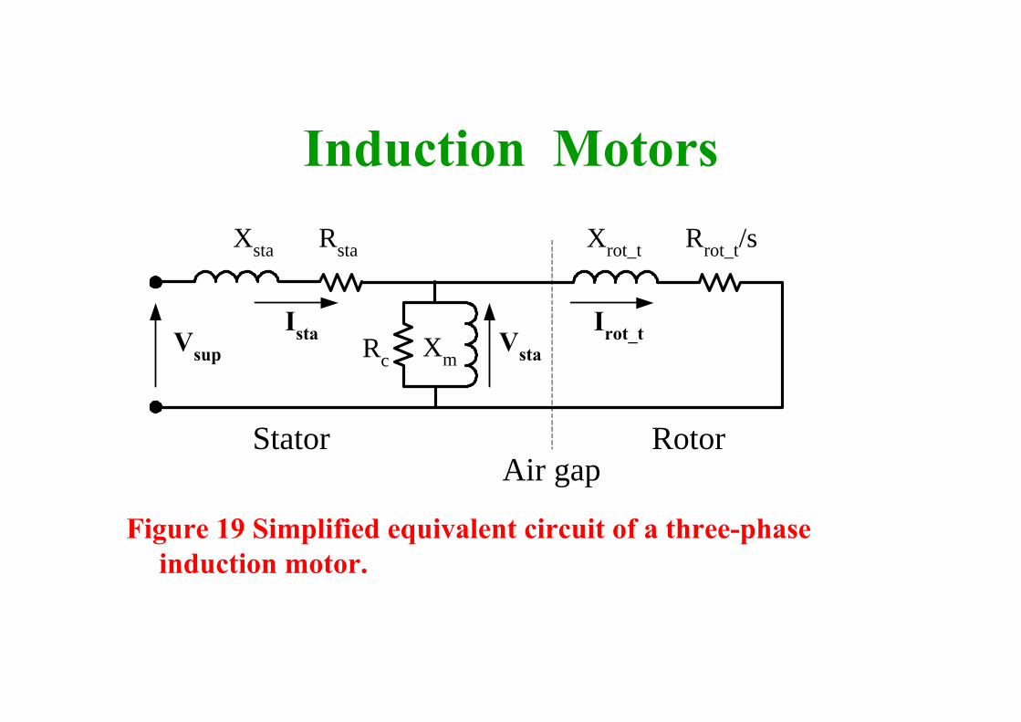
Figure 19 Simplified equivalent circuit of a three-phase induction motor.
Stator Rotor
Xsta Xrot_t Rrot_t/s
Irot_tVsta
Rsta
VsupIsta XmRc
Air gap
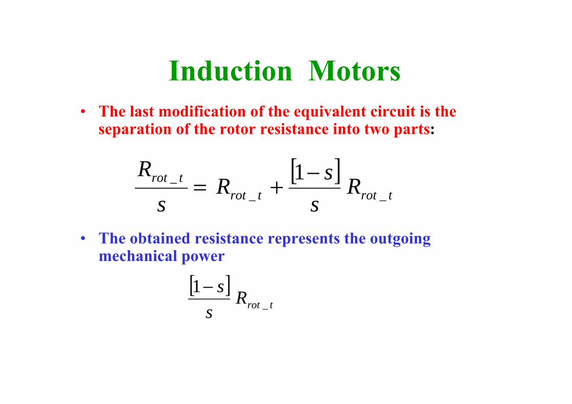
Induction Motors• The last modification of the equivalent circuit is the
separation of the rotor resistance into two parts:
• The obtained resistance represents the outgoing mechanical power
[ ]trottrot
trot Rs
sRs
R__
_ 1−+=
[ ]trotR
ss
_1−
Induction Motors
Stator Rotor
Xsta Xrot_t Rrot_t
Irot_tVsta
Rsta
VsupIsta XmRc
Air gap
Rrot_t(1-s)/s
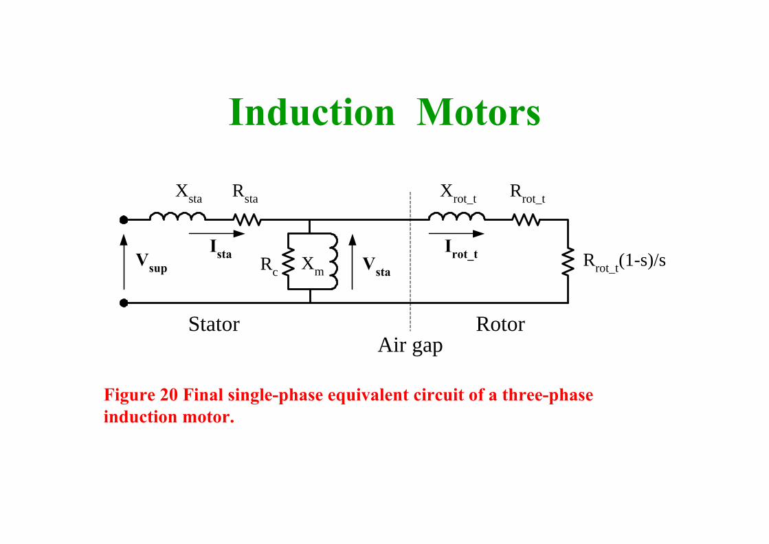
Figure 20 Final single-phase equivalent circuit of a three-phase induction motor.
Motor performance
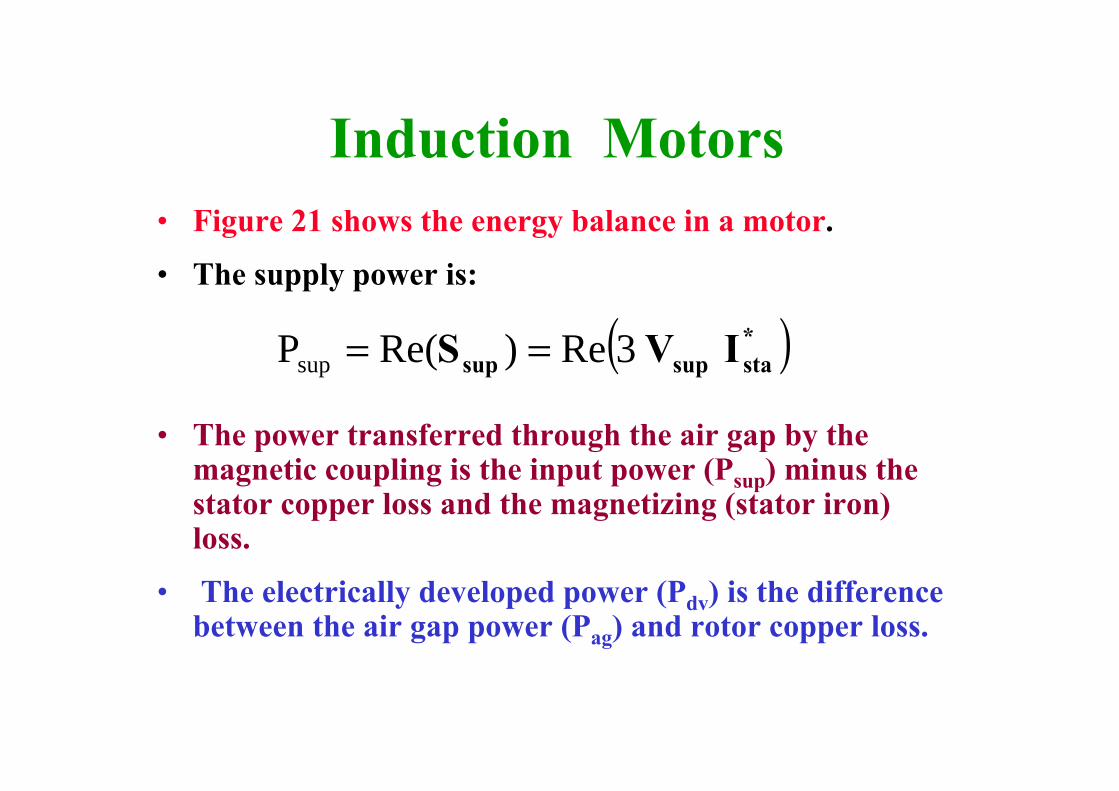
Induction Motors• Figure 21 shows the energy balance in a motor.
• The supply power is:
• The power transferred through the air gap by the magnetic coupling is the input power (Psup) minus the stator copper loss and the magnetizing (stator iron) loss.
• The electrically developed power (Pdv) is the difference between the air gap power (Pag) and rotor copper loss.
( )*stasupsup IVS 3Re)Re(Psup ==

Induction Motors
• The electrically developed power can be computed from the power dissipated in the second term of rotor resistance:
• The subtraction of the mechanical ventilation and friction losses (Pmloss) from the developed power gives the mechanical output power
⎟⎠⎞
⎜⎝⎛ −=
ssR trot
13P _
2
dv rot_tI
mlossdvout PPP −=
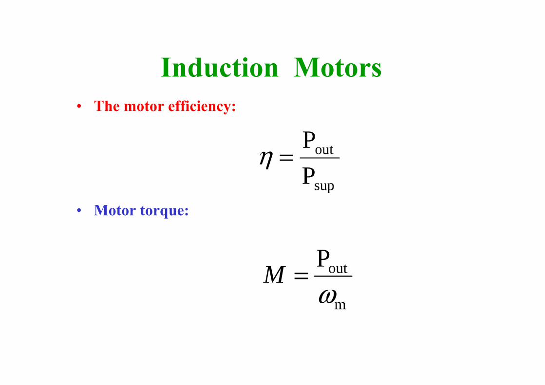
Induction Motors• The motor efficiency:
• Motor torque:sup
out
PP
=η
m
outPω
=M

Induction Motors
Input powerPsup
Stator Copper loss3 Ista
2 Rsta
Rotor Copper loss3 Irot
2 RrotStator Iron loss
3 Vsta2 / Rc
Ventilation andfriction losses
Output powerPout
Air gappower Pag
Developed powerPdv = 3 Irot
2 Rrot (1-s)/s
Air gap
Figure 21 Motor energy balance flow diagram.
7.3.4 Motor performanceanalysis
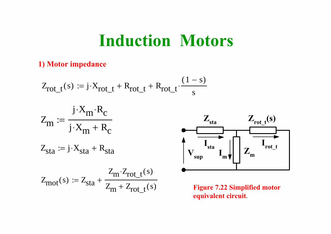
Induction Motors1) Motor impedance
Vsup
Zsta Zrot_t(s)
Zm
Ista Irot_tIm
Figure 7.22 Simplified motor equivalent circuit.
Zrot_t s( ) j Xrot_t⋅ Rrot_t+ Rrot_t1 s−( )
s⋅+:=
Zmj Xm⋅ Rc⋅
j Xm⋅ Rc+:=
Zmot s( ) ZstaZm Zrot_t s( )⋅
Zm Zrot_t s( )++:=
Zsta j Xsta⋅ Rsta+:=
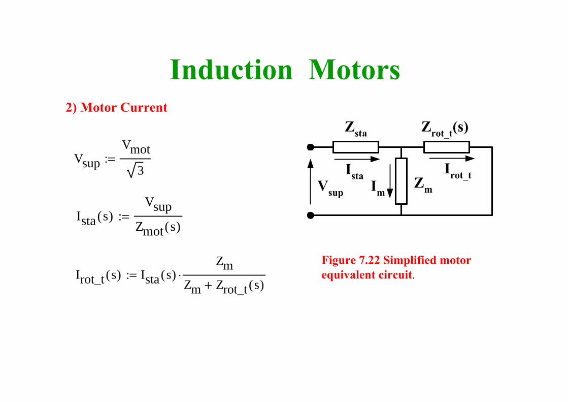
Induction Motors2) Motor Current
Figure 7.22 Simplified motor equivalent circuit.
VsupVmot
3:= Vsup 254.034 V=
Ista s( )Vsup
Zmot s( ):=
Irot_t s( ) Ista s( )Zm
Zm Zrot_t s( )+⋅:=
Vsup
Zsta Zrot_t(s)
Zm
Ista Irot_tIm
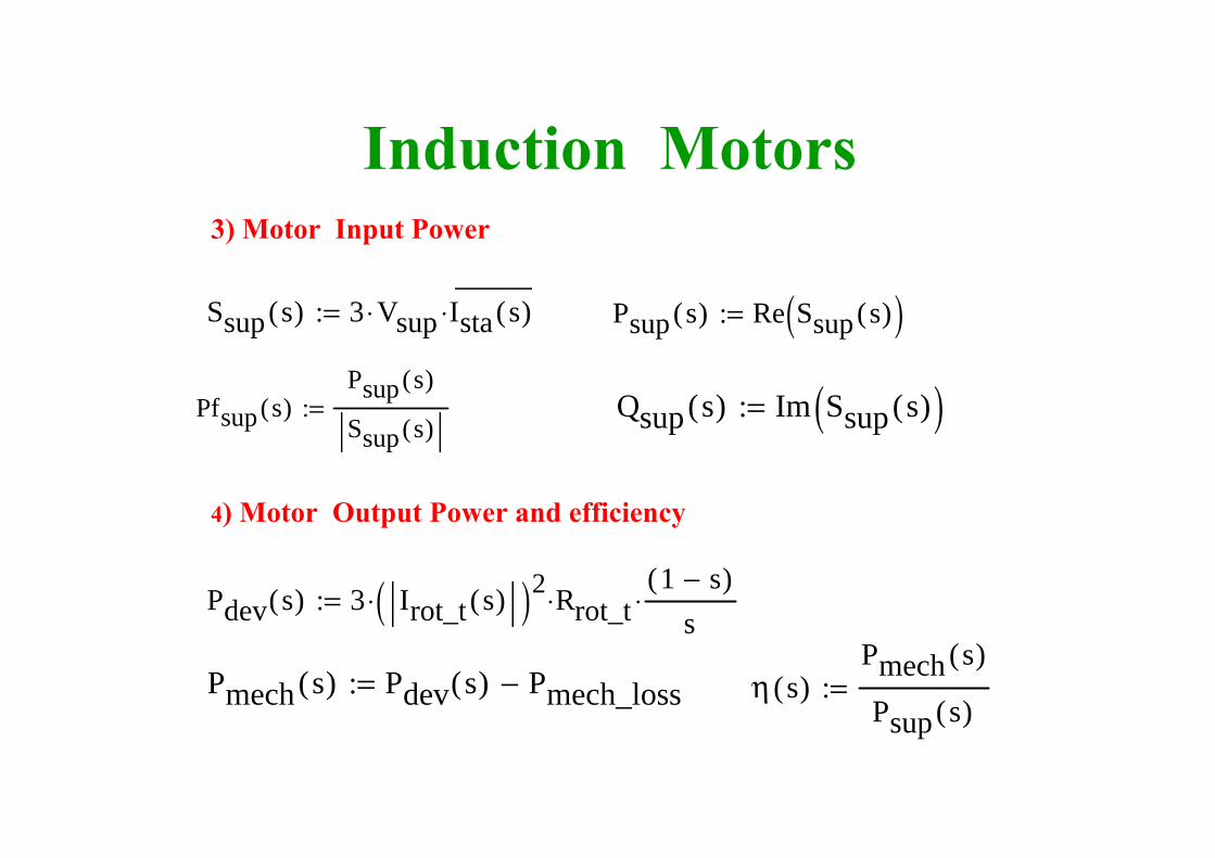
Induction Motors3) Motor Input Power
Ssup s( ) 3 Vsup⋅ Ista s( )⎯
⋅:= Psup s( ) Re Ssup s( )( ):=
Pfsup s( )Psup s( )
Ssup s( ):= Qsup s( ) Im Ssup s( )( ):=
4) Motor Output Power and efficiency
Pdev s( ) 3 Irot_t s( )( )2⋅ Rrot_t⋅1 s−( )
s⋅:=
Pmech s( ) Pdev s( ) Pmech_loss−:= η s( )Pmech s( )
Psup s( ):=
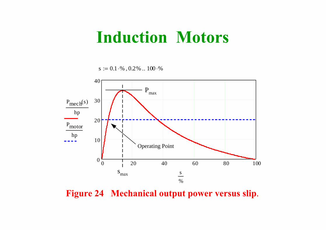
Induction Motorss 0.1 %⋅ 0.2%, 100 %⋅..:=
0 20 40 60 80 1000
10
20
30
40
Pmech s( )
hp
Pmotorhp
s%
Pmax
smax
Operating Point
Figure 24 Mechanical output power versus slip.
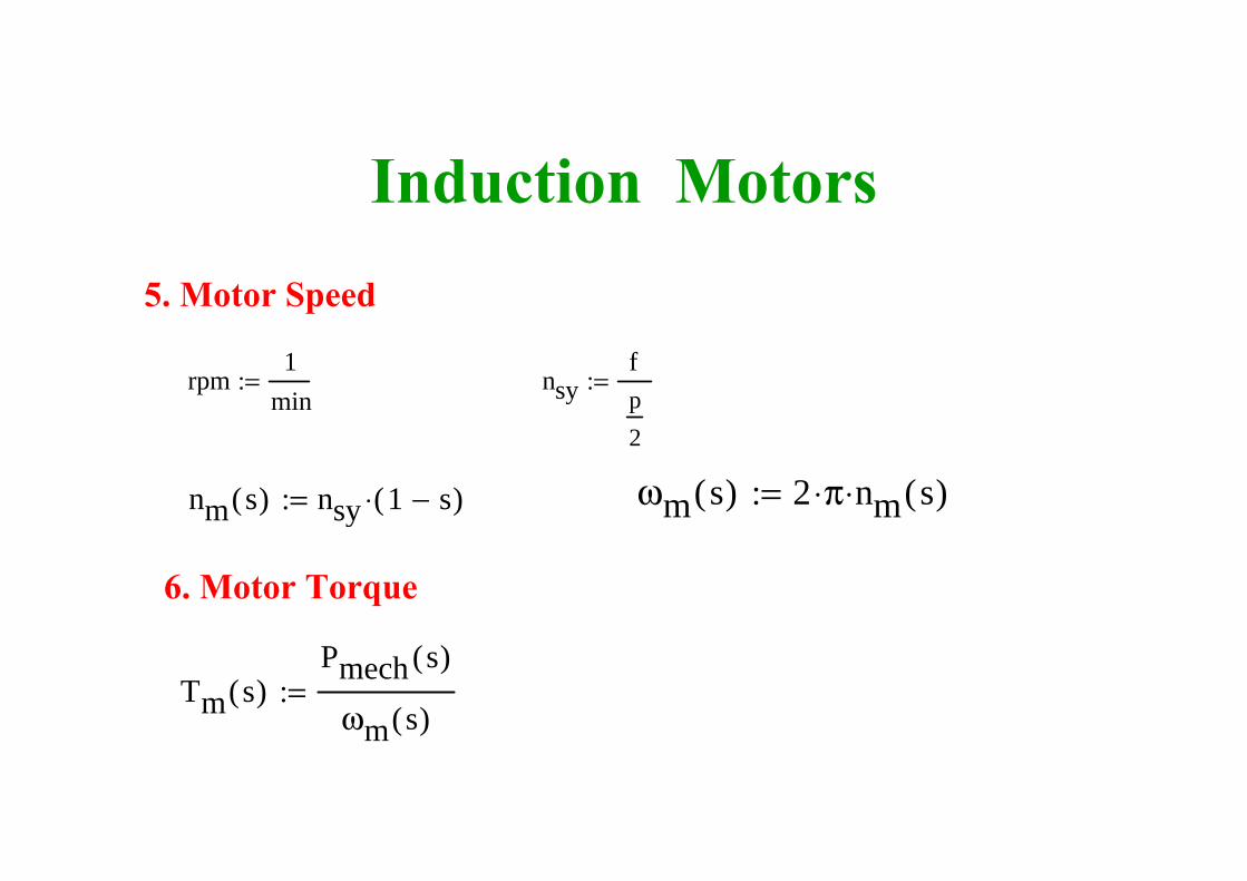
Induction Motors5. Motor Speed
rpm1
min:= nsy
fp2
:= nsy 1800rpm=
nm s( ) nsy 1 s−( )⋅:= ωm s( ) 2 π⋅ nm s( )⋅:=
6. Motor Torque
Tm s( )Pmech s( )
ωm s( ):=
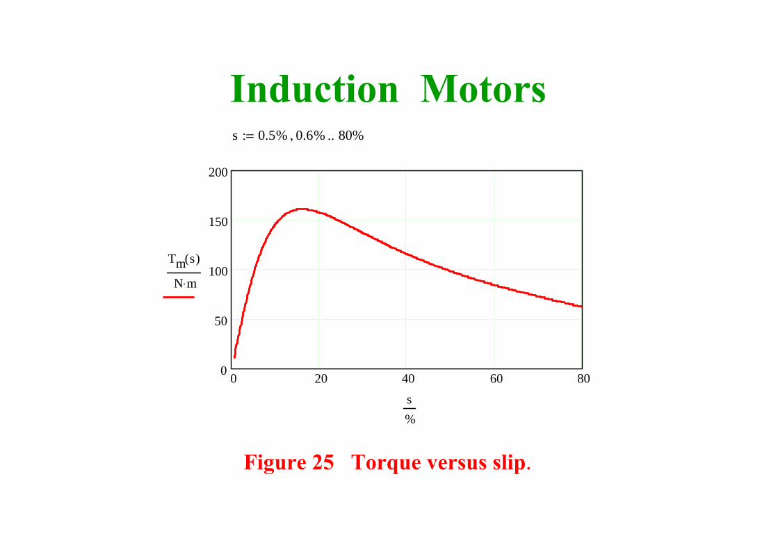
Induction Motors
Figure 25 Torque versus slip.
s 0.5% 0.6%, 80%..:=
0 20 40 60 800
50
100
150
200
Tm s( )
N m⋅
s%
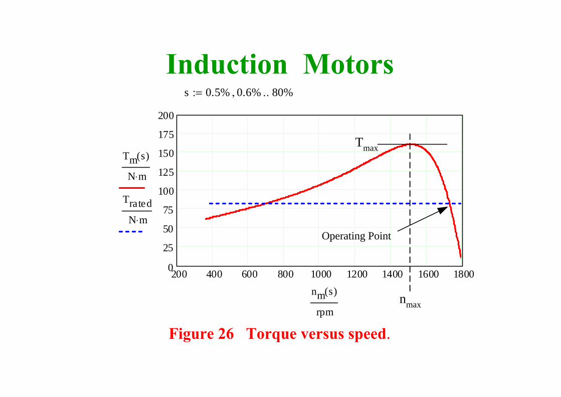
Induction Motors
Figure 26 Torque versus speed.
nmax
s 0.5% 0.6%, 80%..:=
200 400 600 800 1000 1200 1400 1600 18000
25
50
75
100
125
150
175
200
Tm s( )
N m⋅
TratedN m⋅
nm s( )
rpm
Tmax
Operating Point
Induction Motors

Induction MotorsMotor Starting torque• When the motor starts at s = 1,• The ventilation losses are zero and the friction
loss is passive. The negative friction loss does not drive the motor backwards.
• The mechanical losses are zero when s = 1• This implies that the starting torque is calculated
from the developed power instead of the mechanical output power.
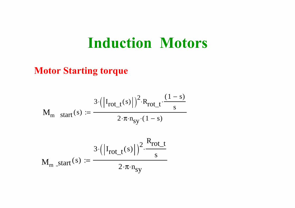
Tm_start s( )3 Irot_t s( )( )2⋅
Rrot_ts
⋅
2 π⋅ nsy⋅:=
Tm_start s( )3 Irot_t s( )( )2⋅ Rrot_t⋅
1 s−( )s
⋅
2 π⋅ nsy⋅ 1 s−( )⋅:=
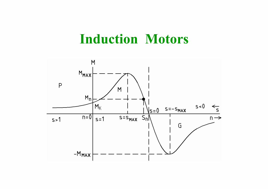
Induction Motors
Motor Starting torque
Mm
Mm
Induction Motors
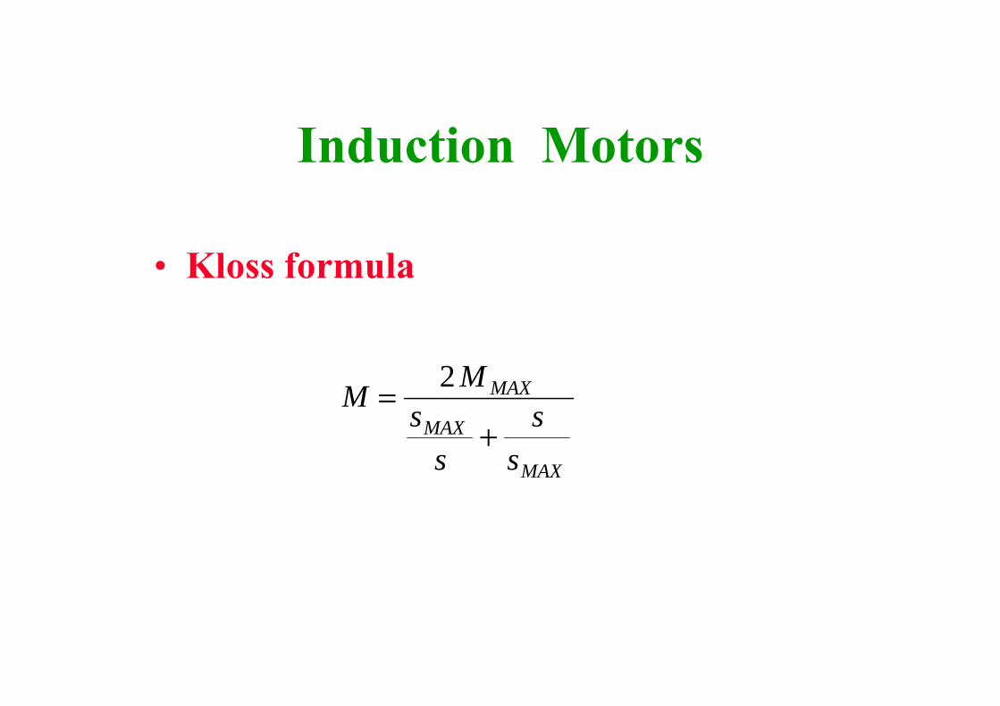
• Kloss formula
M Ms
ss
s
MAX
MAX
MAX
=+
2
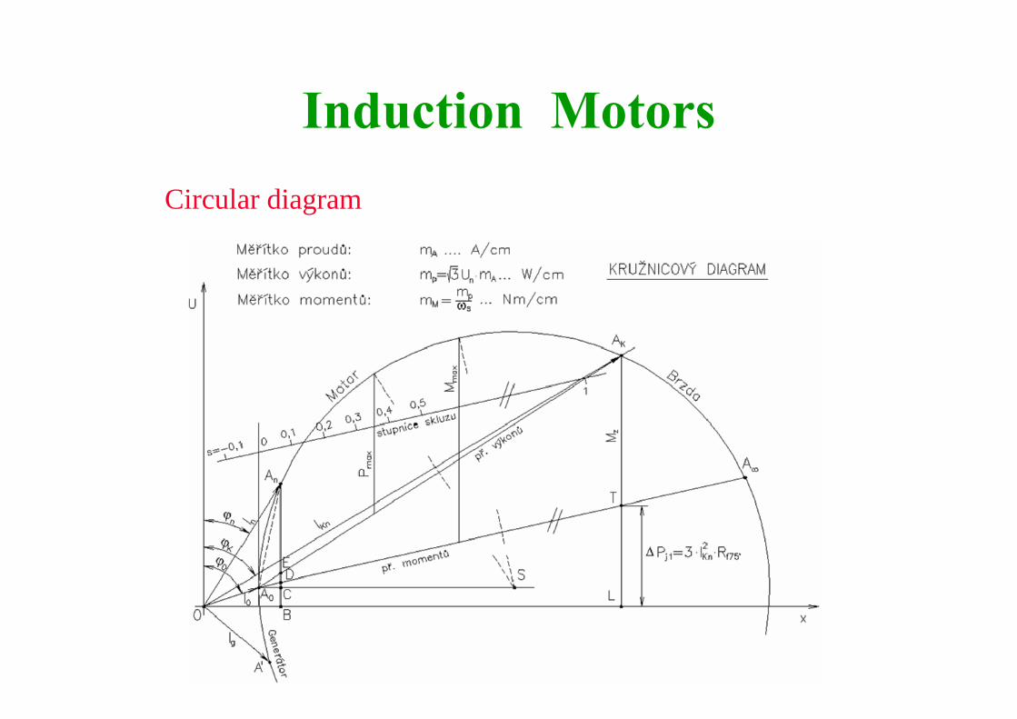
Induction MotorsCircular diagram
Induction Motors
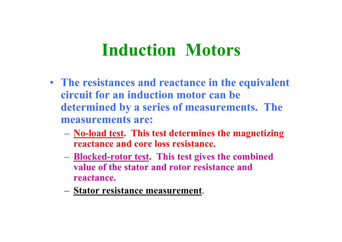
• The resistances and reactance in the equivalent circuit for an induction motor can be determined by a series of measurements. The measurements are:– No-load test. This test determines the magnetizing
reactance and core loss resistance.– Blocked-rotor test. This test gives the combined
value of the stator and rotor resistance and reactance.
– Stator resistance measurement.

Induction Motors
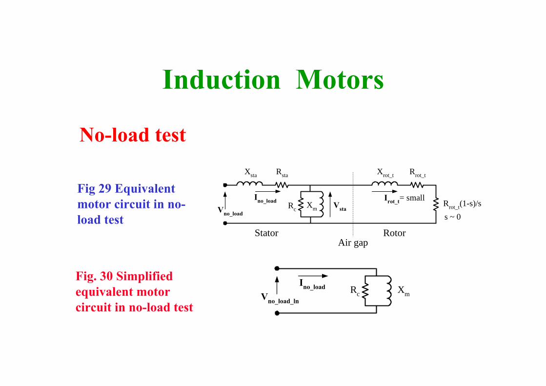
No-load test• The motor shaft is free • The rated voltage supplies the motor.
• In the case of a three-phase motor:– the line-to-line voltages, – line currents– three-phase power using two wattmeters are
measured
Induction Motors
No-load test
Stator Rotor
Xsta Xrot_t Rrot_t
Irot_t= smallVsta
Rsta
Vno_loadXmRc
Air gap
Rrot_t(1-s)/ss ~ 0
Ino_load
Fig 29 Equivalent motor circuit in no-load test
Fig. 30 Simplified equivalent motor circuit in no-load test
Ino_load XmRcVno_load_ln

Induction Motors
No-load test
Vno_load_lnVno_load
3:= Vno_load_ln 120.089 V=
Pno_load_APno_load
3:= Pno_load_A 95W=
RcVno_load_ln
2
Pno_load_A:=
Sno_load_A Vno_load_ln Ino_load⋅:=
Qno_load_A Sno_load_A2 Pno_load_A
2−:=
XmVno_load_ln
2
Qno_load_A:=
Induction Motors
Blocked-rotor test• The rotor is blocked to prevent rotation• The supply voltage is reduced until the motor current is
around the rated value. • The motor is supplied by reduced voltage and reduced
frequency. The supply frequency is typically 15 Hz.• In the case of a three-phase motor:
– the line-to-line voltages, – line currents– three-phase power using two wattmeters are measured
Induction Motors
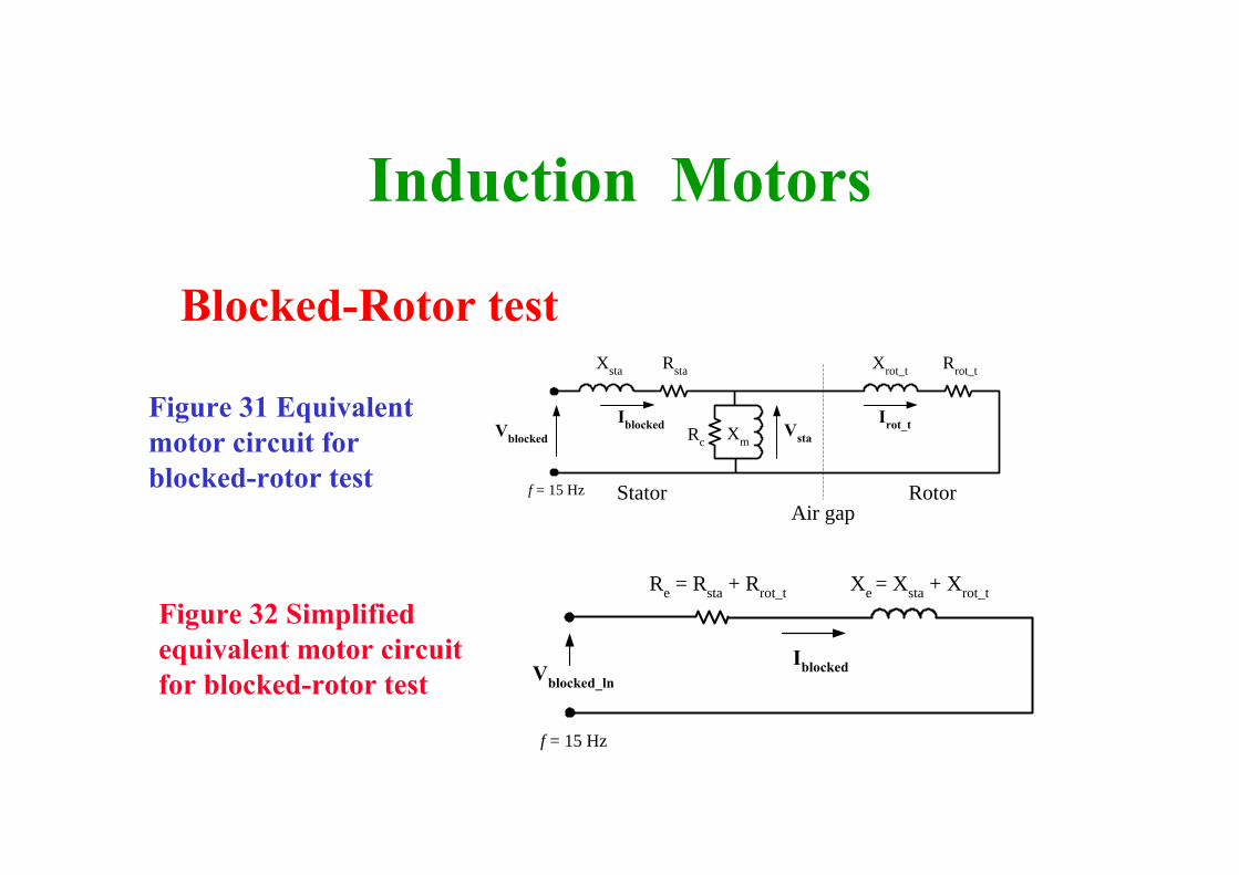
Blocked-Rotor test
Figure 32 Simplified equivalent motor circuit for blocked-rotor test
Figure 31 Equivalent motor circuit for blocked-rotor test Stator Rotor
Xsta Xrot_t Rrot_t
Irot_tVsta
Rsta
Vblocked
Iblocked XmRc
Air gapf = 15 Hz
Xe = Xsta + Xrot_tRe = Rsta + Rrot_t
f = 15 Hz
Vblocked_lnIblocked
Induction Motors
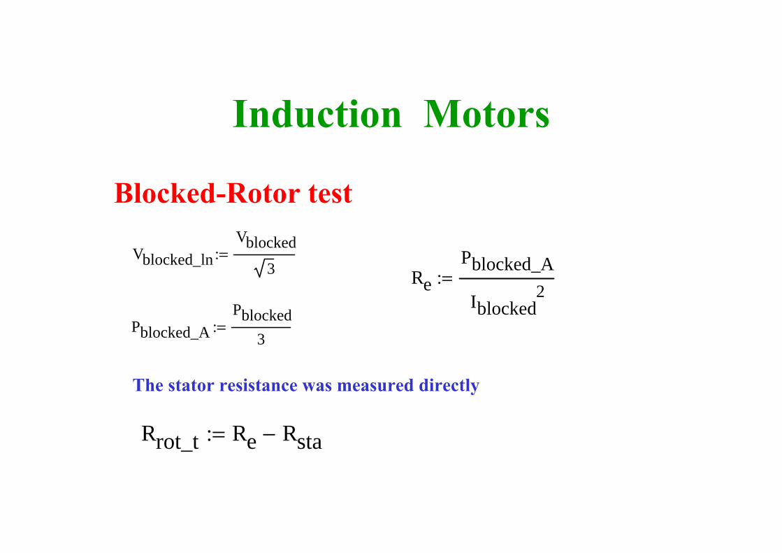
Blocked-Rotor test
Vblocked_lnVblocked
3:= Vblocked_ln 21.939 V=
Pblocked_APblocked
3:= Pblocked_A 160W=
RePblocked_A
Iblocked2
:=
Rrot_t Re Rsta−:=
The stator resistance was measured directly
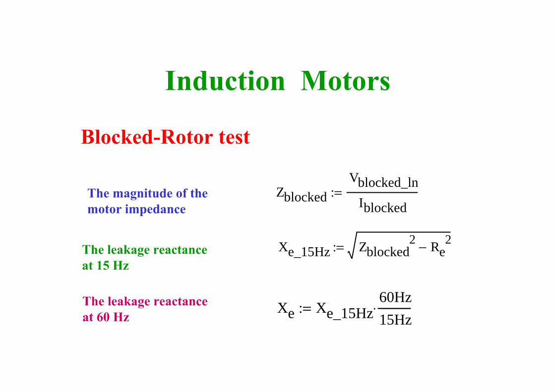
Induction Motors
Blocked-Rotor test
The leakage reactance at 15 Hz
ZblockedVblocked_ln
Iblocked:=The magnitude of the
motor impedance
Xe_15Hz Zblocked2 Re
2−:=
The leakage reactance at 60 Hz Xe Xe_15Hz
60Hz15Hz
⋅:=

Numerical Example
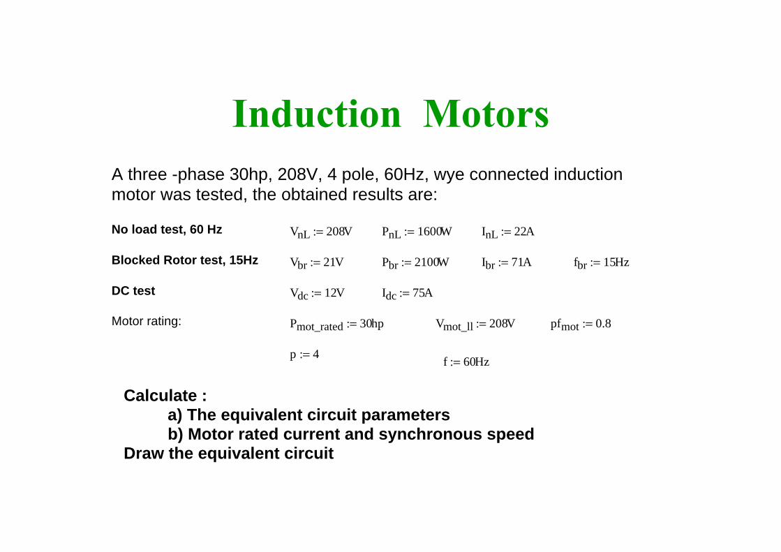
Induction Motors
f 60Hz:=p 4:=
pfmot 0.8:=Vmot_ll 208V:=Pmot_rated 30hp:=Motor rating:
Idc 75A:=Vdc 12V:=DC test
fbr 15Hz:=Ibr 71A:=Pbr 2100W:=Vbr 21V:=Blocked Rotor test, 15Hz
InL 22A:=PnL 1600W:=VnL 208V:=No load test, 60 Hz
A three -phase 30hp, 208V, 4 pole, 60Hz, wye connected induction motor was tested, the obtained results are:
Calculate :a) The equivalent circuit parametersb) Motor rated current and synchronous speed
Draw the equivalent circuit
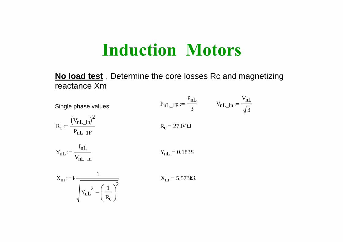
Induction MotorsNo load test , Determine the core losses Rc and magnetizing reactance Xm
PnL_1FPnL
3:= VnL_ln
VnL
3:=Single phase values:
RcVnL_ln( )2
PnL_1F:= Rc 27.04Ω=
YnLInL
VnL_ln:= YnL 0.183S=
Xm i1
YnL2 1
Rc
⎛⎜⎝
⎞⎠
2−
⋅:= Xm 5.573iΩ=

Induction MotorsBlock Rotor test,Neglect the magnetizing branch. Consider only the Xsta+Xrot and Rsta+ Rrot
Xbr Xsta Xrot+ Rbr Rsta Rrot+
Single phase values: Pbr_1FPbr
3:= Vbr_ln
Vbr
3:=
Resistance value is:
RbrPbr_1F
Ibr2
:= Rbr 0.139Ω=
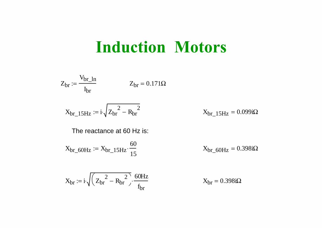
Induction Motors
ZbrVbr_ln
Ibr:= Zbr 0.171Ω=
Xbr_15Hz i Zbr2 Rbr
2−⋅:= Xbr_15Hz 0.099iΩ=
The reactance at 60 Hz is:
Xbr_60Hz Xbr_15Hz6015
⋅:= Xbr_60Hz 0.398iΩ=
Xbr i Zbr2 Rbr
2−⎛⎝
⎞⎠⋅
60Hzfbr
⋅:= Xbr 0.398iΩ=
Induction Motors
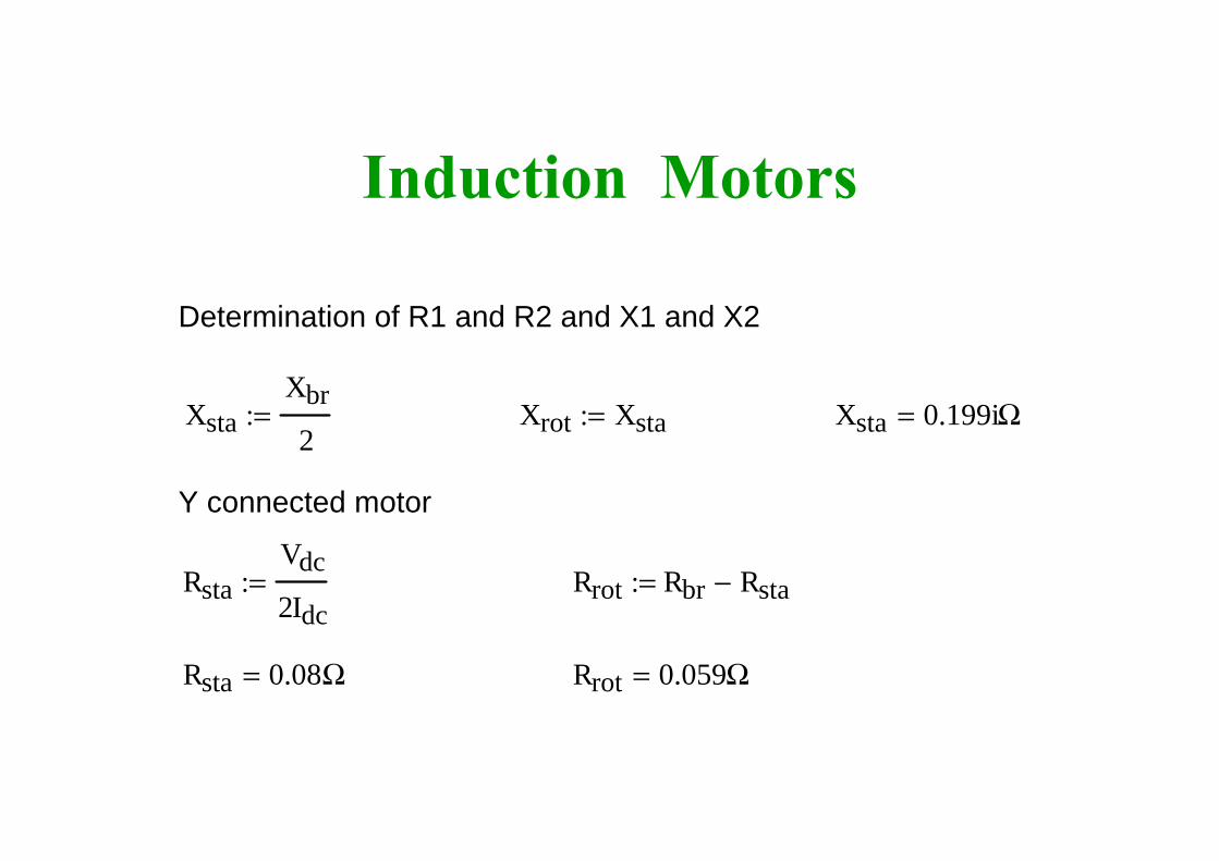
Determination of R1 and R2 and X1 and X2
XstaXbr
2:= Xrot Xsta:= Xsta 0.199iΩ=
Y connected motor
RstaVdc
2Idc:= Rrot Rbr Rsta−:=
Rsta 0.08Ω= Rrot 0.059Ω=
Induction Motors
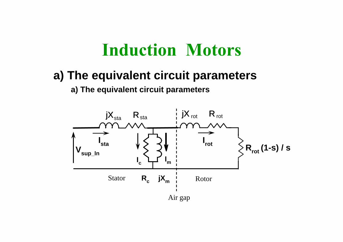
a) The equivalent circuit parameters
Rotor
Air gap
Stator
sta
Ic Im
jXmRc
stajX RjX RjX R
IstaVsup_ln
Irot
rotjX RjX RjX Rrot
Rrot (1-s) / s
a) The equivalent circuit parameters
Induction Motors
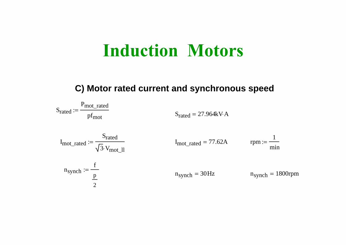
C) Motor rated current and synchronous speed
SratedPmot_rated
pfmot:= Srated 27.964kV A⋅=
Imot_ratedSrated
3 Vmot_ll⋅:= Imot_rated 77.62A= rpm
1min
:=
nsynchfp
2
:= nsynch 30Hz= nsynch 1800rpm=