Single Phase Induction Motor - Ústav přístrojové a...
27
Single Phase Induction Motor
-
Upload
trinhnguyet -
Category
Documents
-
view
254 -
download
12
Transcript of Single Phase Induction Motor - Ústav přístrojové a...
Single Phase Induction Motor
Single Phase Induction Motor
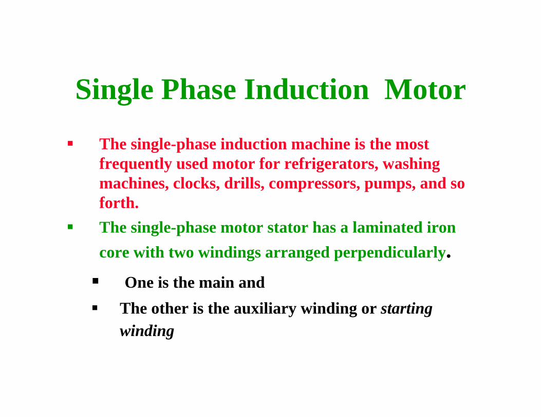
The single-phase induction machine is the most frequently used motor for refrigerators, washing machines, clocks, drills, compressors, pumps, and so forth.The single-phase motor stator has a laminated iron core with two windings arranged perpendicularly.
One is the main and The other is the auxiliary winding or starting winding
Single Phase Induction Motor

Single Phase Induction Motor• This “single-phase”
motors are truly two-phase machines.
• The motor uses a squirrel cage rotor, which has a laminated iron core with slots.
• Aluminum bars are molded on the slots and short-circuited at both ends with a ring.
Stator with laminatediron core Slots with winding
Bars
Ring to shortcircuit the barsStarting winding
+
_
Main winding
Rotor withlaminatediron core+
_
Figure 42 Single-phase induction motor.

Single Phase Induction Motor
Figure 10 Squirrel cage rotor

Operating principle

Single Phase Induction Motor
• The single-phase induction motor operation can be described by two methods:
– Double revolving field theory; and
– Cross-field theory.
• Double revolving theory is perhaps the easier of the two explanations to understand
• Learn the double revolving theory only

Single Phase Induction Motor
Double revolving field theory• A single-phase ac current supplies the main
winding that produces a pulsating magnetic field.
• Mathematically, the pulsating field could be divided into two fields, which are rotating in opposite directions.
• The interaction between the fields and the current induced in the rotor bars generates opposing torque

Single Phase Induction Motor
• The interaction between the fields and the current induced in the rotor bars generates opposing torque.
• Under these conditions, with only the main field energized the motor will not start
• However, if an external torque moves the motor in any direction, the motor will begin to rotate.
Starting winding
Main winding+ωt-ωt
Main winding flux
Figure 43 Single-phase motor main winding generates two rotating fields, which oppose and counter-balance one another.

Single Phase Induction Motor
Double revolving field theory• The pulsating filed is divided a forward and reverse
rotating field
• Motor is started in the direction of forward rotating field this generates small (5%) positive slip
• Reverse rotating field generates a larger (1.95%) negative slip
symsypos nnns )( −=
symsyneg nnns )( +=

Single Phase Induction Motor
Double revolving field theory• The three-phase induction motor starting torque inversely
depends on the slip
• This implies that a small positive slip (0.01–0.03) generates larger torque than a larger negative slip (1.95–1.99)
• This torque difference drives the motor continues to rotate in aforward direction without any external torque.
Tm_start s( )3 Irot_t s( )( )2⋅
Rrot_ts
⋅
2 π⋅ nsy⋅:=
Single Phase Induction Motor
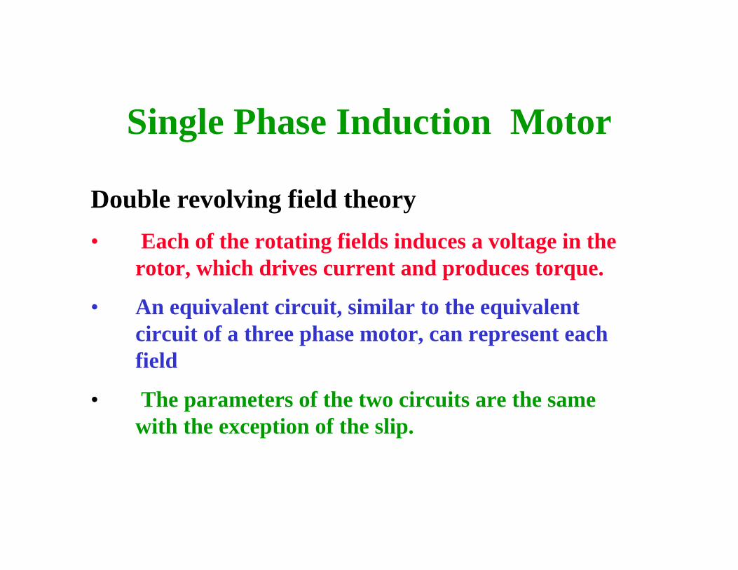
Double revolving field theory• Each of the rotating fields induces a voltage in the
rotor, which drives current and produces torque.
• An equivalent circuit, similar to the equivalent circuit of a three phase motor, can represent each field
• The parameters of the two circuits are the same with the exception of the slip.
Single Phase Induction Motor
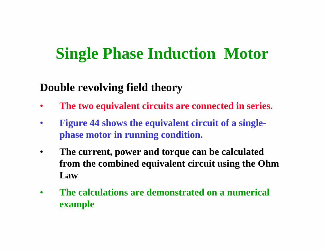
Double revolving field theory• The two equivalent circuits are connected in series.
• Figure 44 shows the equivalent circuit of a single-phase motor in running condition.
• The current, power and torque can be calculated from the combined equivalent circuit using the Ohm Law
• The calculations are demonstrated on a numerical example

Single Phase Induction Motor
Forwardrotating field
Xsta/2
Vsta
Ista
Rrot(1-spos)/(2spos)
Rsta/2
Rc/2 Xm/2
Xrot/2 Rrot/2
Reverserotating field
Xsta/2
Rrot(1-sneg)/(2sneg)
Rsta/2
Rc/2 Xm/2
Xrot/2 Rrot/2
Ipos
Ineg
Figure 44 Equivalent circuit of a single-phase motor in running condition.
Single Phase Induction Motor
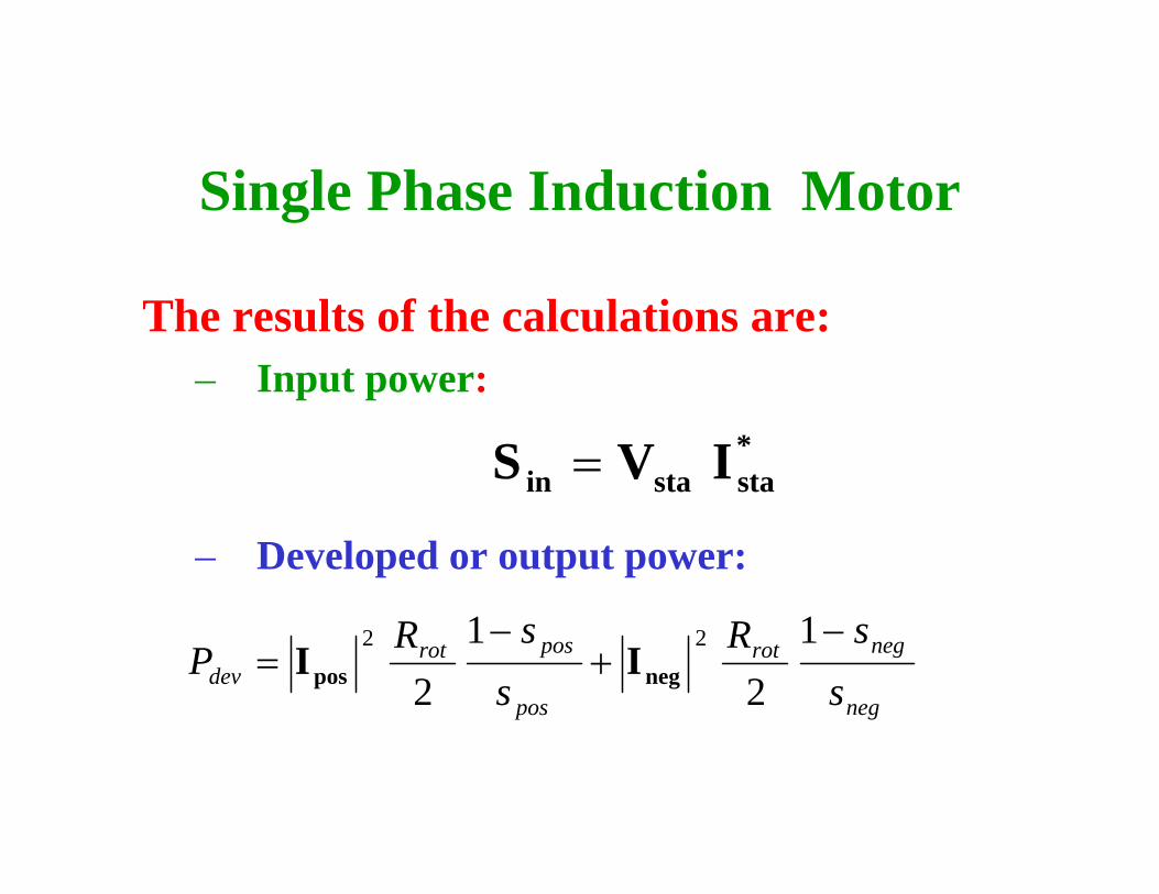
The results of the calculations are:– Input power:
– Developed or output power:
*stastain IVS =
neg
negrot
pos
posrotdev s
sRs
sRP
−+
−=
12
12
22
negpos II

Single Phase Induction Motornm 400rpm 410rpm, 1780rpm..:=
400 600 800 1000 1200 1400 1600 18000
100
200
300
400
500
Pmech nm( )W
Pmot_dev nm( )W
Pmech nrated( )W
nm
rpm
Pdev_max
nmax
Operating Point
Pmech_max
StableOperating
Region
Figure 47 Single-phase motor mechanical output power and electrically developed power versus speed.

Starting torque
Single Phase Induction Motor
• The single-phase motor starting torque is zero because of the pulsating single-phase magnetic flux.
• The starting of the motor requires the generation of a rotating magnetic flux similar to the rotating flux in a three-phase motor.
• Two perpendicular coils that have currents 90° out-of-phase can generate the necessary rotating magnetic fields which start the motor.
• Therefore, single-phase motors are built with two perpendicular windings.

Single Phase Induction Motor
• The phase shift is achieved by connecting
– a resistance, – an inductance, or – a capacitance
in series with the starting winding.• Most frequently used is a capacitor to
generate the starting torque.

Single Phase Induction Motor
• Figure 50 shows the connection diagram of a motor using a capacitor to generate the starting torque.
• When the motor reaches the operating speed, a centrifugal switch turns off the starting winding.
I
C
Mainwinding
Rotor
Centrifugal switch
V Startingwinding
Figure 50 Single-phase motor connection.

Single Phase Induction Motor
• The centrifugal switch is necessary because most motors use a cheap electrolytic capacitor that can only carry ac current for a short period.
• A properly selected capacitor produces around 90° phase shift and large starting torque.
I
C
Mainwinding
Rotor
Centrifugal switch
V Startingwinding
Figure 50 Single-phase motor connection.

Single Phase Induction Motor
Operating Point
nm 0.1rpm 1rpm, nsy..:=
0 500 1000 15000
2
4
6
8
10
12
Tsm nm( )N m⋅
Tm nm( )N m⋅
T nm( )N m⋅
Tnom
N m⋅
nm
rpm
Starting windingis disconnected
Main windinggenerated torque
Combined main andstarting windingsgenerated torque Figure 51
Torque–speed characteristic of a small single-phase induction motor.

Single Phase Induction Motor
• A less effective but more economical method using shaded pole motors
• The motor has two salient poles excited by ac current.
• Each pole includes a small portion that has a short-circuited winding. This part of the pole is called the shaded pole.
• The main winding produces a pulsating flux that links with the squirrel cage rotor.
• This flux induces a voltage in the shorted winding.
Single Phase Induction Motor
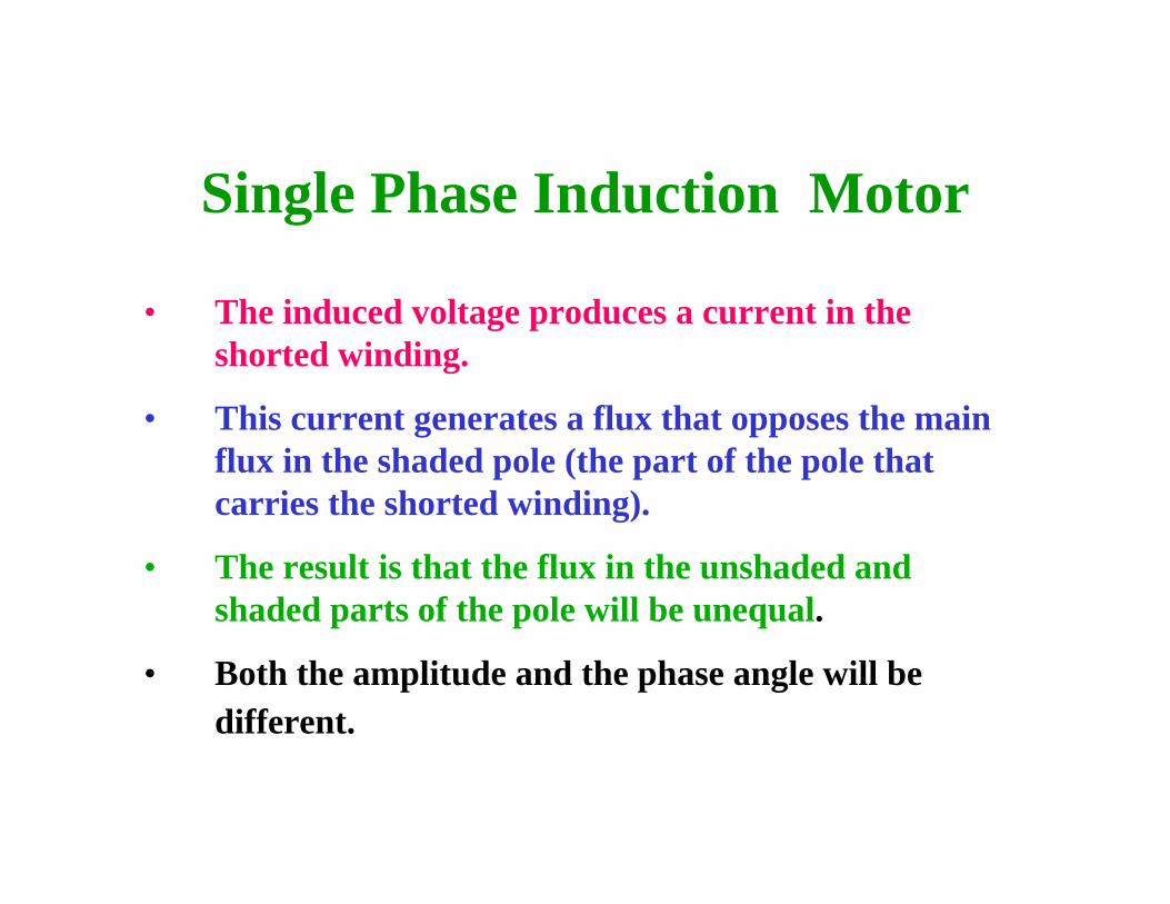
• The induced voltage produces a current in the shorted winding.
• This current generates a flux that opposes the main flux in the shaded pole (the part of the pole that carries the shorted winding).
• The result is that the flux in the unshaded and shaded parts of the pole will be unequal.
• Both the amplitude and the phase angle will be different.
Single Phase Induction Motor
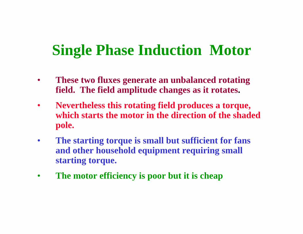
• These two fluxes generate an unbalanced rotating field. The field amplitude changes as it rotates.
• Nevertheless this rotating field produces a torque, which starts the motor in the direction of the shaded pole.
• The starting torque is small but sufficient for fans and other household equipment requiring small starting torque.
• The motor efficiency is poor but it is cheap
Single Phase Induction Motor
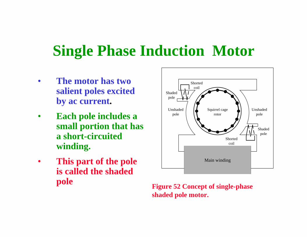
• The motor has two salient poles excited by ac current.
• Each pole includes a small portion that has a short-circuited winding.
• This part of the pole is called the shaded pole
Main winding
Shortedcoil
Unshadedpole
Unshadedpole
Shadedpole
Shadedpole
Shortedcoil
Squirrel cagerotor
Figure 52 Concept of single-phase shaded pole motor.

Single Phase Induction Motor
Figure 53Shaded pole motor for household fan.