
Expansion Phase –I (3X800 MW). OPGW & Its Accessories – TL ...
66
Transcript of Expansion Phase –I (3X800 MW). OPGW & Its Accessories – TL ...
400kV GIS at Patratu Super Thermal Power Project Expansion Phase –I (3X800 MW).
OPGW & Its Accessories – TL Diversion Doc. No. : TB-397-510-008 Rev 00
Page 2 of 8
SECTION-1
Scope, Bill of Quantity, Specific Technical Requirements 1.1 Scope
This technical specification covers the requirements of design, manufacture, testing at works, packing, dispatch of Overhead Optical Fiber Grounding Wire (OPGW) complete with accessories as listed under this specification. This section covers the specific technical requirements of Overhead Optical Fiber Grounding Wire (OPGW). This constitutes minimum technical parameters for the above item as specified by the customer (PVUNL). The offered equipment shall also comply with the General Technical Requirements for the project as detailed under section-3 of this specification.
The scope shall include and encompass all the activities listed above. The equipment is required for the following project: Name of the customer : Patratu Vidyut Utpadan Nigam Ltd. (PVUNL)
(A Subsidiary of NTPC in Joint Venture with JBVNL)
Name of the project : 400kV GIS at Patratu Super Thermal Power Project
Expansion Phase –I (3X800 MW)
Site : Patratu, Jharkhand *Note: The terms used in this specification namely, “Employer/Purchaser” refers to
PVUNL , “Contractor” refers to BHEL. Refer section-3 of this document for project details and general specification. In case of any conflict among the various sections of this specification, the order of precedence shall be section 1, section 2 & the section 3.

400kV GIS at Patratu Super Thermal Power Project Expansion Phase –I (3X800 MW).
OPGW & Its Accessories – TL Diversion Doc. No. : TB-397-510-008 Rev 00
Page 3 of 8
1.2 Bill of Quantities 1.2.1 Main Equipment:
SN Description Unit Quantity at Patratu TPS
End 1 Supply: 24 FIBRE OPGW CABLE km 1.6
2 Supply: OPGW CABLE ACCESSORIES – OPGW SUSPENSION CLAMPS
Nos 20
3 Supply: OPGW CABLE ACCESSORIES – WAY JOINT BOX FOR OPGW
Nos
1
4 Supply: OPGW CABLE ACCESSORIES – OPGW TENSION CLAMPS (SINGLE, WITH EARTHING BONDS)
Nos 20
5 Supply: OPGW CABLE ACCESSORIES – OPGW GROUNDING AND PARALLEL GROOVE/DOWNLEAD CLAMPS
Nos 40
6 Supply: OPGW CABLE ACCESSORIES – OPGW VIBRATION DAMPERS
Nos 40
7 Supply: OPGW CABLE ACCESSORIES – ARMOR RODS FOR OPGW
Nos 20
8 Services: Termination and Splicing of OPGW Nos 2 Notes:
1. Total PO value may vary by ±20%, however individual items can vary to any extent. Some line items may be deleted.
2. The OPGW cable to be supplied as per the above requirement is required to be connected to the main transmission line OPGW at the interface point of plant boundary. The diameter and other details of the existing OPGW cable shall be provided to the successful bidder during detailed engineering stage.
3. The OPGW cable to be supplied as per the TS shall be suitable for connecting with the existing OPGW cable.
1.3 Type Tests
a) OPGW and its accessories are to be supplied shall be of type tested design. During detail engineering, the Bidder shall submit for Owner’s approval the reports of all the type tests as listed in this specification and carried out not earlier than ten years prior to the date of techno-commercial bid opening i.e 03-Mar-2017. These reports should be for the test conducted on the equipment similar to those proposed to be supplied under this contract and the test(s) should have been either conducted at an independent laboratory or should have been witnessed by a Client.

400kV GIS at Patratu Super Thermal Power Project Expansion Phase –I (3X800 MW).
OPGW & Its Accessories – TL Diversion Doc. No. : TB-397-510-008 Rev 00
Page 4 of 8
b) However if Bidder is not able to submit report of the type test(s) conducted not earlier than ten years prior to the date of techno-commercial bid opening, or in the case of type test report(s) are not found to be meeting the specification requirements, the Bidder shall conduct all such tests under this contract at no additional cost to the owner either at third party lab or in presence of client/ owners representative and submit the reports for approval.
c) All acceptance and routine tests as per the specification and relevant standards shall
be carried out. Charges for these shall be deemed to be included in the equipment price.
d) Refer section 2 for details of type tests required.
1.4 Quality Plan, Inspection, Testing And Acceptance
Bidder to follow valid NTPC approved quality plan at contract stage. In case the bidder does not have NTPC approved QP, it will be the bidder’s responsibility to get its QP approved from NTPC/BHEL before inspection of material.
1.5 DOCUMENTATION:
The successful bidder shall have to extend all possible supports like timely submission/resubmission of drawings, visit to end customer to facilitate documents approval without any commercial implications to BHEL. Acceptance of bidder’s documents shall be subject to end customer approval. Date of Submission of first lot of drawings will be counted only from the date of submission of reasonably correct drawings. List of drawings required for technical clearance of manufacturing are as follows: 1. Approved GTP 2. Approved GA/Drawings/ BOM. 3. Approved Type Test Reports.
1.6 DOCUMENTS REQUIRED DURING TENDER STAGE:
Following documents are required during tender stage: a) Clause wise compliance to the specification b) Available catalogs of offered items c) Filled checklist d) Un-priced Bill of Quantity
400kV GIS at Patratu Super Thermal Power Project Expansion Phase –I (3X800 MW).
OPGW & Its Accessories – TL Diversion Doc. No. : TB-397-510-008 Rev 00
Page 5 of 8
1.7 Special Tools & Tackles
The bidder shall include in his proposal the deployment of all special tools and tackles required for erection, testing, commissioning and maintenance of the equipment. The Special tools and tackles shall only cover items which are specifically required for the equipment offered and are proprietary in nature. A list of all such devices shall be furnished by the bidder.
1.8 Deviations
The bidder shall list all the deviation from the specification separately. Offers without specific deviation will be deemed to be totally in compliance with the specification and NO DEVIATION on any account will be entertained at a later date.

400kV GIS at Patratu Super Thermal Power Project Expansion Phase –I (3X800 MW).
OPGW & Its Accessories – TL Diversion Doc. No. : TB-397-510-008 Rev 00
Page 6 of 8
SECTION-2
Refer NTPC Document: CS-0370-572-2 Technical Specifications (NABINAGAR STPP 3X660MW 400/132kV SWITCHYARD PACKAGE)


400kV GIS at Patratu Super Thermal Power Project Expansion Phase –I (3X800 MW).
OPGW & Its Accessories – TL Diversion Doc. No. : TB-397-510-008 Rev 00
Page 7 of 8
SECTION-3 Refer document
General Technical Requirements – TB-397-316-000 Rev 00.
PROJECT: PATRATU SUPER THERMAL POWER PROJECT EXPANSION PHASE–I (3X 800MW)CUSTOMER: PATRATU VIDYUT UTPADAN NIGAM LTD. (PVUNL) (A Subsidiary of NTPC in Joint Venture with JBVNL)Technical Specification TB-397-316-000 Rev 00 Section-3: Project Details and General Specification
Section-3 Page 1 of 31
SECTION- 3
PROJECT DETAILS AND GENERAL SPECIFICATIONS
3.0 GENERAL
This section stipulates the General Technical Requirements under the Contract and will form an integral part of the Technical Specification.
The provisions under this section are intended to supplement general requirements for the materials, equipment and services covered under other sections of tender documents and are not exclusive. However in case of conflict between the requirements specified in this section and requirements specified under other sections, the requirements specified under respective sections shall prevail.
3.1 PROJECT DETAILS
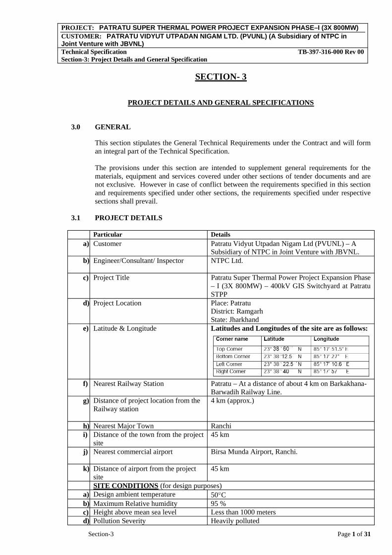
Particular Detailsa) Customer Patratu Vidyut Utpadan Nigam Ltd (PVUNL) – A
Subsidiary of NTPC in Joint Venture with JBVNL.b) Engineer/Consultant/ Inspector NTPC Ltd.
c) Project Title Patratu Super Thermal Power Project Expansion Phase – I (3X 800MW) – 400kV GIS Switchyard at Patratu STPP
d) Project Location Place: Patratu District: Ramgarh State: Jharkhand
e) Latitude & Longitude Latitudes and Longitudes of the site are as follows:
f) Nearest Railway Station Patratu – At a distance of about 4 km on Barkakhana-Barwadih Railway Line.
g) Distance of project location from the Railway station
4 km (approx.)
h) Nearest Major Town Ranchi i) Distance of the town from the project
site45 km
j) Nearest commercial airport Birsa Munda Airport, Ranchi.
k) Distance of airport from the project site
45 km
SITE CONDITIONS (for design purposes) a) Design ambient temperature 50 Cb) Maximum Relative humidity 95 % c) Height above mean sea level Less than 1000 meters d) Pollution Severity Heavily polluted

PROJECT: PATRATU SUPER THERMAL POWER PROJECT EXPANSION PHASE–I (3X 800MW)CUSTOMER: PATRATU VIDYUT UTPADAN NIGAM LTD. (PVUNL) (A Subsidiary of NTPC in Joint Venture with JBVNL)Technical Specification TB-397-316-000 Rev 00 Section-3: Project Details and General Specification
Section-3 Page 2 of 31
e) Criteria for Wind Resistant design of structures and equipment
Standard Applicable - IS 875 (Part 3)
f) Basic Wind speed “Vb” at ten meters above the mean ground level.
39 m/ sec
g) Category of terrain Cat –2 h) Risk Coefficient “K1” 1.06
3.1.1 SYSTEM PARAMETERS:
Sl.No. Parameters 400 kV 1 Highest system voltage 420 kV rms 2 Lightning Impulse voltage ±1425kVp 3 Switching impulse voltage ±1050kVp 4 Power frequency withstand for 1 min (rms) 650 kV(rms) 5 Max. fault level (1 sec.) 63 kA 6 Minimum creepage distance 10500 mm
3.1.2 AUXILIARY POWER:
Sl.No. Nominal Connection Voltage
Variationsin Voltage
Frequency Phase Neutral
1 415V ±10% 50 (+3% -5%) 3Phase , 4 Wire
Solidly Earthed
2 240V ±10% 50 (+3% -5%) 1 phase Solidly Earthed
Combined variation of voltage and frequency shall be + 10%. Design fault level of 415V system shall be restricted to 50kA rms for 1 second.
The operational limits for variation of DC voltage are (+) 10% to (-) 15%.
3.1.3 The various minimum heights of the AIS switchyard shall be as given below from plinth level:
Voltage Equipment /1st Level Line Take Off Gantry Height Peak 400kV 8000mm 23000mm 8500mm
The minimum vertical distance from the bottom of the lowest porcelain part of the bushing, porcelain enclosures or support insulators to the bottom of the equipment structure, where it rests on the foundation pad shall be 2550mm.
The minimum height of intermediate gantry tower for 400kV wherever required shall be 25 m and the peak (s) shall be of 8.5 m. The gantry width for 400kV AIS shall be minimum 27m or as required to meet the specified clearances.
3.1.4 The minimum clearances for 400kV switchyards shall be as given below:
400kVPhase to earth clearance 3500 mm Phase to phase clearance 4000 mm Section clearance 6500 mm
PROJECT: PATRATU SUPER THERMAL POWER PROJECT EXPANSION PHASE–I (3X 800MW)CUSTOMER: PATRATU VIDYUT UTPADAN NIGAM LTD. (PVUNL) (A Subsidiary of NTPC in Joint Venture with JBVNL)Technical Specification TB-397-316-000 Rev 00 Section-3: Project Details and General Specification
Section-3 Page 3 of 31
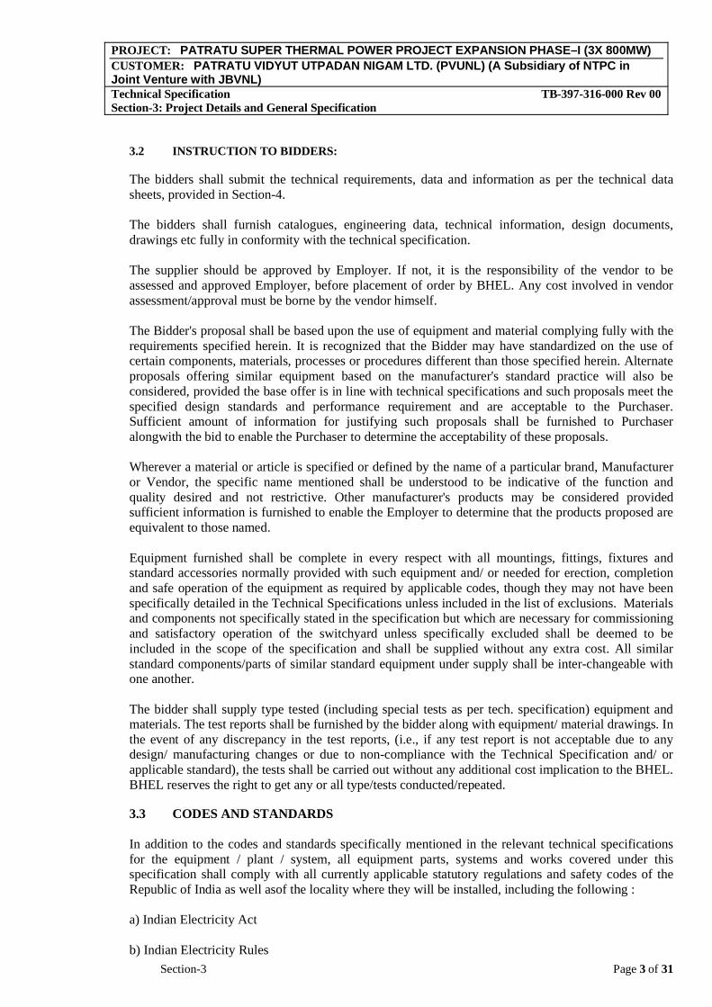
3.2 INSTRUCTION TO BIDDERS:
The bidders shall submit the technical requirements, data and information as per the technical data sheets, provided in Section-4.
The bidders shall furnish catalogues, engineering data, technical information, design documents, drawings etc fully in conformity with the technical specification.
The supplier should be approved by Employer. If not, it is the responsibility of the vendor to be assessed and approved Employer, before placement of order by BHEL. Any cost involved in vendor assessment/approval must be borne by the vendor himself.
The Bidder's proposal shall be based upon the use of equipment and material complying fully with the requirements specified herein. It is recognized that the Bidder may have standardized on the use of certain components, materials, processes or procedures different than those specified herein. Alternate proposals offering similar equipment based on the manufacturer's standard practice will also be considered, provided the base offer is in line with technical specifications and such proposals meet the specified design standards and performance requirement and are acceptable to the Purchaser. Sufficient amount of information for justifying such proposals shall be furnished to Purchaser alongwith the bid to enable the Purchaser to determine the acceptability of these proposals.
Wherever a material or article is specified or defined by the name of a particular brand, Manufacturer or Vendor, the specific name mentioned shall be understood to be indicative of the function and quality desired and not restrictive. Other manufacturer's products may be considered provided sufficient information is furnished to enable the Employer to determine that the products proposed are equivalent to those named.
Equipment furnished shall be complete in every respect with all mountings, fittings, fixtures and standard accessories normally provided with such equipment and/ or needed for erection, completion and safe operation of the equipment as required by applicable codes, though they may not have been specifically detailed in the Technical Specifications unless included in the list of exclusions. Materials and components not specifically stated in the specification but which are necessary for commissioning and satisfactory operation of the switchyard unless specifically excluded shall be deemed to be included in the scope of the specification and shall be supplied without any extra cost. All similar standard components/parts of similar standard equipment under supply shall be inter-changeable with one another.
The bidder shall supply type tested (including special tests as per tech. specification) equipment and materials. The test reports shall be furnished by the bidder along with equipment/ material drawings. In the event of any discrepancy in the test reports, (i.e., if any test report is not acceptable due to any design/ manufacturing changes or due to non-compliance with the Technical Specification and/ or applicable standard), the tests shall be carried out without any additional cost implication to the BHEL. BHEL reserves the right to get any or all type/tests conducted/repeated.
3.3 CODES AND STANDARDS
In addition to the codes and standards specifically mentioned in the relevant technical specifications for the equipment / plant / system, all equipment parts, systems and works covered under this specification shall comply with all currently applicable statutory regulations and safety codes of the Republic of India as well asof the locality where they will be installed, including the following :
a) Indian Electricity Act
b) Indian Electricity Rules
PROJECT: PATRATU SUPER THERMAL POWER PROJECT EXPANSION PHASE–I (3X 800MW)CUSTOMER: PATRATU VIDYUT UTPADAN NIGAM LTD. (PVUNL) (A Subsidiary of NTPC in Joint Venture with JBVNL)Technical Specification TB-397-316-000 Rev 00 Section-3: Project Details and General Specification
Section-3 Page 4 of 31
c) Indian Explosives Act
d) Indian Factories Act and State Factories Act
e) Indian Boiler Regulations (IBR)
f) Regulations of the Central Pollution Control Board, India
g) Regulations of the Ministry of Environment & Forest (MoEF), Government of India
h) Pollution Control Regulations of Department of Environment, Government of India
i) State Pollution Control Board.
(j.) Rules for Electrical installation by Tariff Advisory Committee (TAC).
(k.) Building and other construction workers (Regulation of Employment and Conditions of services) Act, 1996
(l.) Building and other construction workers (Regulation of Employment and Conditions of services) Central Rules, 1998
(m.) Explosive Rules, 1983
(n.) Petroleum Act, 1984
(o.) Petroleum Rules, 1976,
(p.) Gas Cylinder Rules, 1981
(q.) Static and Mobile Pressure Vessels (Unified) Rules, 1981
(r.) Workmen's Compensation Act, 1923
(s.) Workmen's Compensation Rules, 1924
(t.) NTPC Safety Rules for Construction and Erection
(u.) NTPC Safety Policy
(v.) Any other statutory codes / standards / regulations, as may be applicable.
Unless covered otherwise in the specifications, the latest editions (as applicable as on date of bid opening: 03-March-2017), of the codes and standards given below shall also apply:
a) Bureau of Indian standards (BIS)
b) Japanese Industrial Standards (JIS)
c) American National Standards Institute (ANSI)
d) American Society of Testing and Materials (ASTM)
e) American Society of Mechanical Engineers (ASME)
PROJECT: PATRATU SUPER THERMAL POWER PROJECT EXPANSION PHASE–I (3X 800MW)CUSTOMER: PATRATU VIDYUT UTPADAN NIGAM LTD. (PVUNL) (A Subsidiary of NTPC in Joint Venture with JBVNL)Technical Specification TB-397-316-000 Rev 00 Section-3: Project Details and General Specification
Section-3 Page 5 of 31
f) American Petroleum Institute (API)
g) Standards of the Hydraulic Institute , U.S.A.
h) International Organization for Standardization (ISO)
i) Tubular Exchanger Manufacturer's Association (TEMA)
j) American Welding Society (AWS)
k) National Electrical Manufacturers Association (NEMA)
l) National Fire Protection Association (NFPA)
m) International Electro-Technical Commission (IEC)
n) Expansion Joint Manufacturers Association (EJMA)
o) Heat Exchange Institute (HEI)
p) IEEE standard
q) JEC standard
Other International/ National standards such as DIN, VDI, BS, GOST etc. shall also be accepted for only material codes and manufacturing standards, subject to the Employer's approval, for which the Bidder shall furnish, adequate information to justify that these standards are equivalent or superior to the standards mentioned above. In all such cases the Bidder shall furnish specifically the variations and deviations from the standards mentioned elsewhere in the specification together with the complete word to word translation of the standard that is normally not published in English.
As regards highly standardized equipment such as Steam Turbine and Generator, National /International standards such as JIS, DIN, VDI, ISO, SEL, SEW, VDE, IEC & VGB shall also be considered as far as applicable for Design, Manufacturing and Testing of the respective equipment. However, for those of the above equipment not covered by these National / International standards, established and proven standards of manufacturers shall also be considered.
In the event of any conflict between the codes and standards referred to in the above clauses and the requirement of this specification, the requirement of Technical Specification shall govern.
In case of any change in codes, standards & regulations between 03-March-2017 and the date when vendors proceed with fabrication, the Employer shall have the option to incorporate the changed requirements or to retain the original standard. It shall be the responsibility of the Contractor to bring to the notice of the Employer such changes and advise Employer of the resulting effect.
3.4 SERVICES TO BE PERFORMED BY THE EQUIPMENT BEING FURNISHED
The 400 kV system is being designed to limit the power frequency over voltage of 1.5 p.u. and the switching surge over voltage to 2.5 p.u. In 400 kV system the initial value of temporary over voltage could be 2.0 p.u. for 1-2 cycles. All the equipment/materials covered in this specification shall perform all its function satisfactorily without undue strain, restrike etc. under such over voltage conditions.
All equipment shall also perform satisfactorily under various other electrical, electromechanical and meteorological conditions of the site of installation. All equipment shall be able to withstand all

PROJECT: PATRATU SUPER THERMAL POWER PROJECT EXPANSION PHASE–I (3X 800MW)CUSTOMER: PATRATU VIDYUT UTPADAN NIGAM LTD. (PVUNL) (A Subsidiary of NTPC in Joint Venture with JBVNL)Technical Specification TB-397-316-000 Rev 00 Section-3: Project Details and General Specification
Section-3 Page 6 of 31
external and internal mechanical, thermal and electromechanical forces due to various factors like wind load, temperature variation, ice & snow (not applicable for this project), short circuit etc for the equipment.
3.5 ENGINEERING DATA
3.5.1 Drawings
All drawings submitted by the supplier including those submitted at the time of bid shall be in sufficient detail to indicate the type, size, arrangement, material description, Bill of Materials, weight of each component, break-up for packing and shipment, the external connections, fixing arrangement required. The dimensions required for installation and interconnections with other equipment and materials, clearances and spaces required for installation and interconnections between various portions of equipment and any other information specifically requested in the specifications.
Each drawing submitted by the bidder (including those of sub-vendors) shall bear a title block at the right hand bottom corner with clear mention of the name of the Employer, the system designation, the specifications title, the specification number, the name of the Project, drawing number and revisions. If standard catalogue pages are submitted, the applicable items shall be indicated therein. All titles, noting, markings and writings on the drawing shall be in English. All the dimensions should be in metric units.
After the approval of the drawings, further work by the bidder shall be in strict accordance with these drawings and no deviation shall be permitted without the written approval of the Purchaser, if so required.
The review of these document/data/drawings by the purchaser will cover only general conformance of the document/data/drawings to the specification and contract, interfaces with the equipment provided under specification, external connections and of the dimensions which might affect plan layout. This review by the purchaser may not indicate a thorough review of the dimensions, quantities and details of the equipment, material, any devices or items indicated or the accuracy of the information submitted. The review and/or approval by the purchaser shall not be considered by the bidder, as limiting any of his responsibilities and liabilities for mistakes and deviations from the requirements, specified under these specifications and documents.
All manufacturing, fabrication and execution of work in connection with the equipment/system prior to the approval of the drawings shall be at the bidder's risk. The bidder is expected not to make any changes in the design of the equipment /system, once they are approved by the Purchaser. However, if some changes are necessitated in the design of the equipment/system at a later date, the bidder may do so, but such changes shall promptly be brought to the notice of the Purchaser indicating the reasons for the change and get the revised drawing approved again in strict conformance to the provisions of the Technical Specification. Approval of bidder’s drawing or work by the Purchaser shall not relieve the bidder of any of his responsibilities and liabilities under the Contract.
All engineering data submitted by the contractor after final process including review and approval by the purchaser shall form part of the contract document and the entire work performed under these specifications shall be performed in strict conformity with technical specification, unless otherwise expressly requested by the purchaser in writing.
3.5.2 Bidder’s Drawing Submission and Approval Procedure
The following procedure for submission and review/approval of the drawings, data reports, information, etc. shall be followed by the bidder:
PROJECT: PATRATU SUPER THERMAL POWER PROJECT EXPANSION PHASE–I (3X 800MW)CUSTOMER: PATRATU VIDYUT UTPADAN NIGAM LTD. (PVUNL) (A Subsidiary of NTPC in Joint Venture with JBVNL)Technical Specification TB-397-316-000 Rev 00 Section-3: Project Details and General Specification
Section-3 Page 7 of 31
a. All data/information furnished by Vendor in the form of drawings, documents, Catalogues or in any other form for Employer’s information/interface and/or review and approval are referred by the general term “drawings”.
b. The ‘Master drawings list’ indicating titles, Drawing Number, Date of submission and approval etc. shall be furnished by the bidder. This list shall be updated if required at suitable interval during detailed engineering.
c. All drawings (including those of sub-vendor) shall bear at the right hand bottom corner the ‘title plate’ with all relevant information duly filled in. The bidder shall furnish this format to his sub-vendor along with his purchase order for sub-vendor’s compliance.
d. Contractor shall submit all the drawings in five (5) copies for review of Employer. Employer shall forward their comments within four (4) weeks of receipt of drawings.
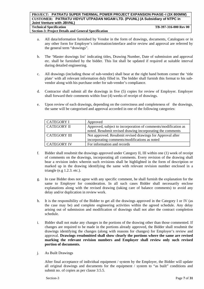
e. Upon review of each drawings, depending on the correctness and completeness of the drawings, the same will be categorised and approval accorded in one of the following categories:
CATEGORY I Approved CATEGORY II Approved, subject to incorporation of comments/modification as
noted. Resubmit revised drawing incorporating the comments CATEGORY III Not approved. Resubmit revised drawings for Approval after
incorporating comments/modifications as noted CATEGORY IV For information and records
f. Bidder shall resubmit the drawings approved under Category II, III within one (1) week of receipt of comments on the drawings, incorporating all comments. Every revision of the drawing shall bear a revision index wherein such revisions shall be highlighted in the form of description or marked up in the drawing identifying the same with relevant revision number enclosed in a triangle (e.g 1.2.3. etc.).
g. In case Bidder does not agree with any specific comment, he shall furnish the explanation for the same to Employer for consideration. In all such cases Bidder shall necessarily enclose explanations along with the revised drawing (taking care of balance comments) to avoid any delay and/or duplication in review work.
h. It is the responsibility of the Bidder to get all the drawings approved in the Category I or IV (as the case may be) and complete engineering activities within the agreed schedule. Any delay arising out of submission and modification of drawings shall not alter the contract completion schedule.
i. Bidder shall not make any changes in the portions of the drawing other than those commented. If changes are required to be made in the portions already approved, the Bidder shall resubmit the drawings identifying the changes (along with reasons for changes) for Employer’s review and approval. Drawings resubmitted shall show clearly the portions where the same are revised marking the relevant revision numbers and Employer shall review only such revised portion of documents.
j. As Built Drawings
After final acceptance of individual equipment / system by the Employer, the Bidder will update all original drawings and documents for the equipment / system to “as built” conditions and submit no. of copies as per clause 3.5.5.
PROJECT: PATRATU SUPER THERMAL POWER PROJECT EXPANSION PHASE–I (3X 800MW)CUSTOMER: PATRATU VIDYUT UTPADAN NIGAM LTD. (PVUNL) (A Subsidiary of NTPC in Joint Venture with JBVNL)Technical Specification TB-397-316-000 Rev 00 Section-3: Project Details and General Specification
Section-3 Page 8 of 31
k. Approval of drawings will not in any way relieve the Bidder of his obligations of furnishing the equipment in accordance with the specification and shall not prevent subsequent rejection if such equipment is later found to be defective.
3.5.3 Erection Drawings.
a. Contractor shall furnish erection drawings for the guidance or commencement of erection or the first shipment, whichever is earlier. These shall generally comprise of fabrication/assembly drawings, various component/part details drawing, assembly, clearance data requirements, etc. The drawings shall contain details of components/ equipment with identification number, match marks, bill of materials, assembly procedures etc.
b. For all major equipment apart from above details, assembly sequence and instructions with check-lists shall be furnished in the form of erection manuals.
3.5.4 Instruction Manual
a. The Contractor shall submit to the Employer preliminary instruction manuals for all the equipments for review. The final instructions manuals incorporating Employer’s comments and complete in all respect shall be submitted at least sixty (60) days before the first shipment of the equipment. The instruction manuals shall contain full details and drawings of all the equipments, the transportation, storage, installation, testing, commissioning, operation and maintenance procedures, etc. separately for each component/equipment along with log record format. These instruction manuals shall be submitted in five (5) copies for approval.
b. If after commissioning and initial operation of the plant, the instruction manuals require any modifications/additions/changes, the same shall be incorporated and the updated final instruction manuals shall be submitted.
c. The operating and maintenance instructions together with drawings (other than shop drawings) of the equipment, as completed, shall have sufficient details to enable the Employer to maintain, dismantle, reassemble and adjust all parts of the equipment. They shall give a step by step procedure for all operations likely to be carried out during the life of the plant/equipment, including erection, testing, commissioning, operation, maintenance dismantling and repair. Each manual shall also include a complete set of approved drawings together with performance/rating curves of the equipment and test certificates, wherever applicable. The contract shall not be considered completed for purpose of taking over until such instructions and drawings have been supplied to the Employer.
d. A separate section of the manual shall be for each size/type of equipment and shall contain a detailed description of construction and operation, together will all relevant pamphlets.
e. The manuals shall include the following a) List of spare parts along with their drawing and catalogues and procedure for ordering spares. b) Lubrication Schedule including charts showing lubrication checking, testing and replacement
procedure to be carried daily, weekly, monthly & at longer intervals to ensure trouble free operation.
f. Where applicable, fault location charts shall be included to facilitate finding the cause of mal-operation or break down.
g. A collection of the manufacturer’s standard leaflets will not accepted to be taken as a compliance of this clause. The manual shall be specifically compiled for the concerned project.

PROJECT: PATRATU SUPER THERMAL POWER PROJECT EXPANSION PHASE–I (3X 800MW)CUSTOMER: PATRATU VIDYUT UTPADAN NIGAM LTD. (PVUNL) (A Subsidiary of NTPC in Joint Venture with JBVNL)Technical Specification TB-397-316-000 Rev 00 Section-3: Project Details and General Specification
Section-3 Page 9 of 31
The Instruction Manuals shall comprise of the following:
3.5.4.1 Erection Manuals
The erection manuals shall be submitted atleast three (3) months prior to the commencement of erection activities of particular equipment/system. The erection manual should contain the following as a minimum.
a) Erection strategy.
b) Sequence of erection.
c) Erection instructions.
d) Critical checks and permissible deviation/tolerances.
e) List of tool, tackles, heavy equipments like cranes, dozers, etc.
f) Bill of Material
g) Procedure for erection and General Safety procedures to followed during erection/installation.
h) Procedure for initial checking after erection.
i) Procedure for testing and acceptance norms.
j) Procedure / Check list for pre-commissioning activities.
k) Procedure / Check list for commissioning of the system.
l) Safety precautions to be followed in electrical supply distribution during erection.
3.5.4.2 Operation and Maintenance Manuals
a) The manual shall be a two rim PVC bound stiff sided binder able to withstand constant usage or where a thicker type is required it shall have locking steel pins, the size of the manual shall not be larger than international size A3. The cover shall be printed with the Project Name, Services covered and Volume / Book number Each section of the manual shall be divided by a stiff divider of the same size as the holder. The dividers shall clearly state the section number and title. All written instructions within the manual not provided by the manufacturers shall be typewritten with a margin on the left hand side.
b) The arrangement and contents of O & M manuals shall be as follows :
1) Chapter 1 - Plant Description : To contain the following sections specific to the equipment/system supplied
(a) Description of operating principle of equipment / system with schematic drawing / layouts.
(b) Functional description of associated accessories / controls. Control interlock protection write up.
PROJECT: PATRATU SUPER THERMAL POWER PROJECT EXPANSION PHASE–I (3X 800MW)CUSTOMER: PATRATU VIDYUT UTPADAN NIGAM LTD. (PVUNL) (A Subsidiary of NTPC in Joint Venture with JBVNL)Technical Specification TB-397-316-000 Rev 00 Section-3: Project Details and General Specification
Section-3 Page 10 of 31
(c) Integrated operation of the equipment along-with the intended system. (This is to be given by the supplier of the Main equipment by taking into account the operating instruction given by the associated suppliers).
(d) Exploded view of the main equipment, associated accessories and auxiliaries with description. Schematic drawing of the equipment along-with its accessories and auxiliaries.
(e) Design data against which the plant performance will be compared.
(f) Master list of equipment, Technical specification of the equipment/ system and approved data sheets.
(g) Identification system adopted for the various components, (it will be of a simple process linked tagging system).
(h) Master list of drawings (as built drawing - Drawings to be enclosed in a separate volume).
2) Chapter 2 - Plant Operation : To contain the following sections specific to the equipment supplied
(a) Protection logics provided for the equipment along-with brief philosophy behind the logic, Drawings etc.
(b) Limiting values of all protection settings.
(c) Various settings of annunciation/interlocks provided.
(d) Start-up and shut down procedure for equipment along-with the associated systems in step mode.
(e) Do's and Don'ts related to operation of the equipment.
(f) Safety precautions to be taken during normal operation. Emergency instruction on total power failure condition/lubrication failure/any other conditions.
(g) Parameters to be monitored with normal value and limiting values.
(h) Equipment isolating procedures.
(i) Trouble shooting with causes and remedial measures.
(j) Routine testing procedure to ascertain healthiness of the safety devices along-with schedule of testing.
(k) Routine Operational Checks, Recommended Logs and Records
(l) Change over schedule if more than one auxiliary for the same purpose is given.
(m) Preservation procedure on long shut down.
(n) System/plant commissioning procedure.

PROJECT: PATRATU SUPER THERMAL POWER PROJECT EXPANSION PHASE–I (3X 800MW)CUSTOMER: PATRATU VIDYUT UTPADAN NIGAM LTD. (PVUNL) (A Subsidiary of NTPC in Joint Venture with JBVNL)Technical Specification TB-397-316-000 Rev 00 Section-3: Project Details and General Specification
Section-3 Page 11 of 31
3) Chapter 3 - Plant Maintenance : To contain the following sections specific to the equipment supplied
(a) Exploded view of each of the equipments. Drawings along-with bill of materials including name, code no. & population.
(b) Exploded view of the spare parts and critical components with dimensional drawings (In case of Electronic cards, the circuit diagram to be given) and spare parts catalogue for each equipment.
(c) List of Special T/ P required for Overhauling /Trouble shooting including special testing equipment required for calibration etc.
(d) Stepwise dismantling and assembly procedure clearly specifying the tools to be used, checks to be made, records to be maintained etc. Clearance to be maintained etc.
(e) Preventive Maintenance schedules linked with running hours/calendar period along-with checks to be carried out.
(f) Overhauling schedules linked with running hours/calendar period along-with checks to be done.
(g) Long term maintenance schedules
(h) Consumables list along-with the estimated quantity required during normal running and during maintenance like Preventive Maintenance and Overhauling.
(i) List of lubricants with their Indian equivalent, Lubrication Schedule including charts showing lubrication checking, testing and replacement procedure to be carried daily, weekly, monthly & at longer intervals to ensure trouble free operation and quantity required for complete replacement.
(j) Tolerance for fitment of various components.
(k) Details of sub vendors with their part no. in case of bought out items.
(l) List of spare parts with their Part No, total population, life expediency & their interchangeability with already supplied spares to NTPC.
(m) List of mandatory and recommended spare list along with manufacturing drawings, material specification & quality plan for fast moving consumable spares.
(n) Lead time required for ordering of spares from the equipment supplier, instructions for storage and preservation of spares.
(o) General information on the equipment such as modification carried out in the equipment from its inception, equipment population in the country / foreign country and list of utilities where similar equipments have been supplied.
After finalization and approval of the Employer, the O & M Manuals shall be submitted as indicated in table below. The Contract shall not be considered to be completed for purposes of taking over until the final Instructions manuals (both erection and O & M manuals have been supplied to the Employer.
PROJECT: PATRATU SUPER THERMAL POWER PROJECT EXPANSION PHASE–I (3X 800MW)CUSTOMER: PATRATU VIDYUT UTPADAN NIGAM LTD. (PVUNL) (A Subsidiary of NTPC in Joint Venture with JBVNL)Technical Specification TB-397-316-000 Rev 00 Section-3: Project Details and General Specification
Section-3 Page 12 of 31
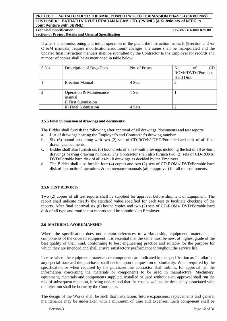
If after the commissioning and initial operation of the plant, the instruction manuals (Erection and /or O &M manuals) require modifications/additions/ changes, the same shall be incorporated and the updated final instruction manuals shall be submitted by the Contractor to the Employer for records and number of copies shall be as mentioned in table below:
S.No. Description of Drgs/Docs No. of Prints No. of CD ROMs/DVDs/PortableHard Disk
1 Erection Manual 4 Sets 2
2 Operation & Maintenance manuali) First Submission
1 Set 1
ii) Final Submission 4 Sets 2
3.5.5 Final Submission of drawings and documents:
The Bidder shall furnish the following after approval of all drawings /documents and test reports: a. List of drawings bearing the Employer’s and Contractor’s drawing number. b. Six (6) bound sets along-with two (2) sets of CD-ROMs/ DVD/Portable hard disk of all final
drawings/documents.c. Bidder shall also furnish six (6) bound sets of all as-built drawings including the list of all as-built
drawings bearing drawing numbers. The Contractor shall also furnish two (2) sets of CD-ROMs/ DVD/Portable hard disk of all as-built drawings as decided by the Employer.
d. The Bidder shall also furnish four (4) copies and two (2) sets of CD-ROMs/ DVD/Portable hard disk of instruction/ operations & maintenance manuals (after approval) for all the equipments.
3.5.6 TEST REPORTS
Two (2) copies of all test reports shall be supplied for approval before shipment of Equipment. The report shall indicate clearly the standard value specified for each test to facilitate checking of the reports. After final approval six (6) bound copies and two (2) sets of CD-ROMs/ DVD/Portable hard disk of all type and routine test reports shall be submitted to Employer.
3.6 MATERIAL /WORKMANSHIP
Where the specification does not contain references to workmanship, equipment, materials and components of the covered equipment, it is essential that the same must be new, of highest grade of the best quality of their kind, conforming to best engineering practice and suitable for the purpose for which they are intended and shall ensure satisfactory performance throughout the service life.
In case where the equipment, materials or components are indicated in the specification as “similar” to any special standard the purchaser shall decide upon the question of similarity. When required by the specification or when required by the purchaser the contractor shall submit, for approval, all the information concerning the materials or components to be used in manufacture. Machinery, equipment, materials and components supplied, installed or used without such approval shall run the risk of subsequent rejection, it being understood that the cost as well as the time delay associated with the rejection shall be borne by the Contractor.
The design of the Works shall be such that installation, future expansions, replacements and general maintenance may be undertaken with a minimum of time and expenses. Each component shall be

PROJECT: PATRATU SUPER THERMAL POWER PROJECT EXPANSION PHASE–I (3X 800MW)CUSTOMER: PATRATU VIDYUT UTPADAN NIGAM LTD. (PVUNL) (A Subsidiary of NTPC in Joint Venture with JBVNL)Technical Specification TB-397-316-000 Rev 00 Section-3: Project Details and General Specification
Section-3 Page 13 of 31
designed to be consistent with its duty and suitable factors of safety subject to mutual agreements. All joints and fastenings shall be devised, constructed and documented so that the component parts shall be accurately positioned and restrained to fulfill their required function. In general, screw threads shall be standard metric threads. The use of other thread forms will only be permitted when prior approval has been obtained from the Purchaser.
Whenever possible, all similar part of the works shall be made to gauge and shall also be made interchangeable with similar parts. All spare parts shall also be interchangeable and shall be made of the same materials and workmanship as the corresponding parts of the equipment supplied under the specification. Where feasible, common component units shall be employed in different pieces of equipment in order to minimize spare parts stocking requirements. All equipment of the same type and rating shall be physically and electrically interchangeable. The equipment offered in the bid only shall be accepted for supply, with the minimum modifications as agreed/accepted.
3.7 PROVISIONS FOR EXPOSURE TO HOT AND HUMID CLIMATE
Outdoor equipment supplied under the specification shall be suitable for service and storage under tropical conditions of high temperature, high humidity' heavy rainfall and environment favorable to the growth of fungi and mildew. The indoor equipment located in non-air-conditioned areas shall also be of same type.
SPACE HEATERS
The heaters shall be suitable for continuous operation at 240 V as supply voltage. On –off switch and fuse shall be provided.
One or more adequately rated thermostatically connected heaters shall be supplied to prevent condensation in any compartment. The heaters shall be installed in the compartment and electrical connections shall be made sufficiently away from below the heaters to minimize deterioration of supply wire insulation. The heaters shall be suitable to maintain the compartment temperature to prevent condensation.
The heaters shall be suitably designed to prevent any contact between the heater wire and the air and shall consist of coiled resistance wire centered in a metal sheath and completely encased in a highly compacted powder of magnesium oxide or other material having equal heat conducting and electrical insulation properties or they shall consist of resistance wire wound on a ceramic and completely covered with a ceramic material to prevent any contact between the wire and the air. Alternatively, they shall consist of a resistance wire mounted into a tubular ceramic body built into an envelope of stainless steel or the resistance wire is wound on a tubular ceramic body and embedded in vitreous glaze. The surface temperature of the heaters shall be restricted to a value which will not shorten the life of the heater sheaths or that of insulated wire or other component in the compartments.
Control cubicles installed in air-conditioned area need not be provided with space heaters. These cubicles shall, however, have space heaters in case of storage of cubicles for long duration.
FUNGI STATIC VARNISH
Besides the space heaters, special moisture and fungus resistance varnish shall be applied on parts which may be subjected or predisposed to the formation of fungi due to the presence or deposit of nutrient substances. The varnish shall not be applied to any surface of part where the treatment will interfere with the operation or performance of the equipment. Such surfaces or parts shall be protected against the application of the varnish.
PROJECT: PATRATU SUPER THERMAL POWER PROJECT EXPANSION PHASE–I (3X 800MW)CUSTOMER: PATRATU VIDYUT UTPADAN NIGAM LTD. (PVUNL) (A Subsidiary of NTPC in Joint Venture with JBVNL)Technical Specification TB-397-316-000 Rev 00 Section-3: Project Details and General Specification
Section-3 Page 14 of 31
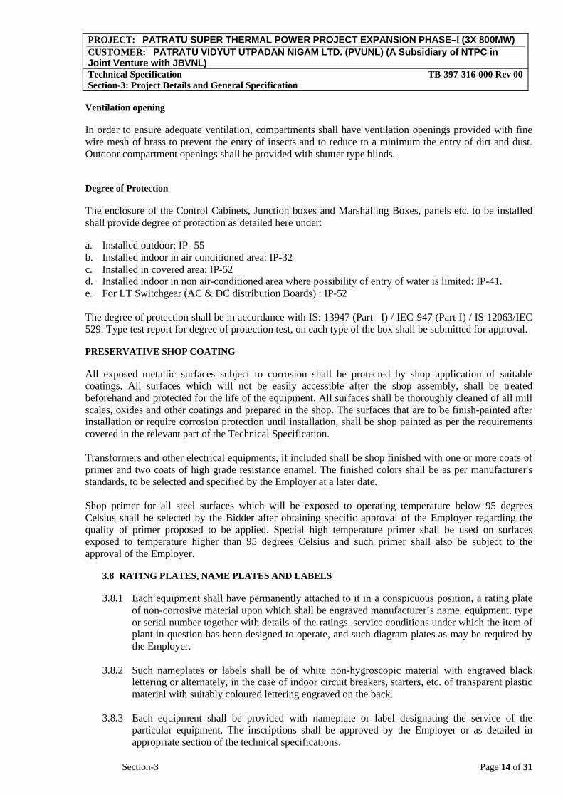
Ventilation opening
In order to ensure adequate ventilation, compartments shall have ventilation openings provided with fine wire mesh of brass to prevent the entry of insects and to reduce to a minimum the entry of dirt and dust. Outdoor compartment openings shall be provided with shutter type blinds.
Degree of Protection
The enclosure of the Control Cabinets, Junction boxes and Marshalling Boxes, panels etc. to be installed shall provide degree of protection as detailed here under:
a. Installed outdoor: IP- 55 b. Installed indoor in air conditioned area: IP-32 c. Installed in covered area: IP-52 d. Installed indoor in non air-conditioned area where possibility of entry of water is limited: IP-41. e. For LT Switchgear (AC & DC distribution Boards) : IP-52
The degree of protection shall be in accordance with IS: 13947 (Part –I) / IEC-947 (Part-I) / IS 12063/IEC 529. Type test report for degree of protection test, on each type of the box shall be submitted for approval.
PRESERVATIVE SHOP COATING
All exposed metallic surfaces subject to corrosion shall be protected by shop application of suitable coatings. All surfaces which will not be easily accessible after the shop assembly, shall be treated beforehand and protected for the life of the equipment. All surfaces shall be thoroughly cleaned of all mill scales, oxides and other coatings and prepared in the shop. The surfaces that are to be finish-painted after installation or require corrosion protection until installation, shall be shop painted as per the requirements covered in the relevant part of the Technical Specification.
Transformers and other electrical equipments, if included shall be shop finished with one or more coats of primer and two coats of high grade resistance enamel. The finished colors shall be as per manufacturer's standards, to be selected and specified by the Employer at a later date.
Shop primer for all steel surfaces which will be exposed to operating temperature below 95 degrees Celsius shall be selected by the Bidder after obtaining specific approval of the Employer regarding the quality of primer proposed to be applied. Special high temperature primer shall be used on surfaces exposed to temperature higher than 95 degrees Celsius and such primer shall also be subject to the approval of the Employer.
3.8 RATING PLATES, NAME PLATES AND LABELS
3.8.1 Each equipment shall have permanently attached to it in a conspicuous position, a rating plate of non-corrosive material upon which shall be engraved manufacturer’s name, equipment, type or serial number together with details of the ratings, service conditions under which the item of plant in question has been designed to operate, and such diagram plates as may be required by the Employer.
3.8.2 Such nameplates or labels shall be of white non-hygroscopic material with engraved black lettering or alternately, in the case of indoor circuit breakers, starters, etc. of transparent plastic material with suitably coloured lettering engraved on the back.
3.8.3 Each equipment shall be provided with nameplate or label designating the service of the particular equipment. The inscriptions shall be approved by the Employer or as detailed in appropriate section of the technical specifications.

PROJECT: PATRATU SUPER THERMAL POWER PROJECT EXPANSION PHASE–I (3X 800MW)CUSTOMER: PATRATU VIDYUT UTPADAN NIGAM LTD. (PVUNL) (A Subsidiary of NTPC in Joint Venture with JBVNL)Technical Specification TB-397-316-000 Rev 00 Section-3: Project Details and General Specification
Section-3 Page 15 of 31
3.8.4 The rated current, extended current rating and rated thermal current shall be clearly indicated in the name plate in case of current transformer.
3.8.5 Rated voltage, voltage factor and intermediate voltage shall be clearly indicated on the nameplate in case of capacitor voltage transformer.
3.8.6 Each switch shall a clear inscription identifying its function. Switches shall also have a clear inscription of each position indication.
3.8.7 All such plates, instruction plates, etc. shall be bilingual with Hindi inscription first, followed by English. Alternatively, two separate plates one with Hindi and the other with English inscriptions may be provided.
3.8.8 All segregated phases of conductors or bus ducts, indoor or outdoor, shall be provided with coloured phase plates to clearly identify the phase of the system.
3.9 GALVANISING:
3.9.1 All exposed ferrous parts shall be hot dip galvanised as per IS:2629 & IS:2633, Galvanising shall be uniform, clean, smooth continuous and free from acid spots. Should the galvanising of the sample be found defective, the entire batch of steel shall have to be re-galvanised at bidder’s cost.
3.9.2 The amount of zinc deposit over threaded portion of the bolts, nuts and screws shall not be less than 300 gms. per sq. meter of surface area. The amount of zinc deposit on washers shall not be less than 340 gms. per sq. meter of surface area or a minimum of 30 microns. The threads shall have extra deposit of zinc which shall be removed by die cutting after the completion of galvanising. The removal of extra zinc shall be carefully done so that threads shall have the required deposits of zinc on them as specified.
3.10 PAINTING
Unless explicitly stated in relevant chapters of the specification, the painting of all electrical equipment shall be as follows: Epoxy based with suitable additives. The thickness of finish coat shall be minimum 50 microns (minimum total DFT shall be 100 microns). However in case electrostatic process of painting is offered for any electrical equipment, minimum paint thickness of 50 microns shall be acceptable for finish coat. Paint shade shall be as per technical specification.
3.11 QUALITY ASSURANCE PROGRAMME
3.11.1 The Bidder shall adopt suitable quality assurance programme to ensure that the equipment and services under the scope of contract whether manufactured or performed within the Bidder’s works or at his subcontractor’s premises or at the Employer’s site or at any other place of work are in accordance with the specifications. Such programmes shall be outlined by the Contractor and shall be finally accepted by the Employer/authorised representative after discussions before the award of the contract. The QA programme shall be generally in line with ISO-9001/IS- 14001.
A quality assurance programme of the contractor shall generally cover the following:
i. His organisation structure for the management and implementation of the proposed quality assurance programme.
ii. Quality System Manual
PROJECT: PATRATU SUPER THERMAL POWER PROJECT EXPANSION PHASE–I (3X 800MW)CUSTOMER: PATRATU VIDYUT UTPADAN NIGAM LTD. (PVUNL) (A Subsidiary of NTPC in Joint Venture with JBVNL)Technical Specification TB-397-316-000 Rev 00 Section-3: Project Details and General Specification
Section-3 Page 16 of 31
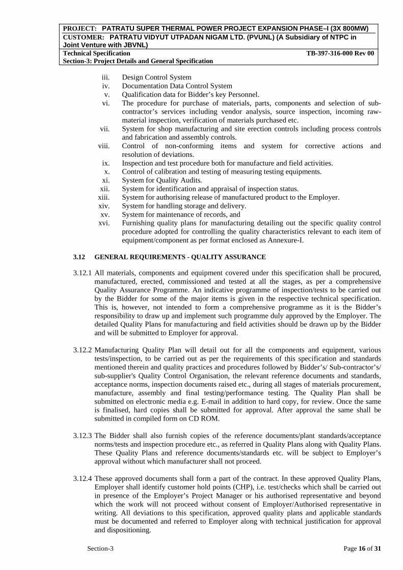
iii. Design Control System iv. Documentation Data Control System v. Qualification data for Bidder’s key Personnel.
vi. The procedure for purchase of materials, parts, components and selection of sub-contractor’s services including vendor analysis, source inspection, incoming raw-material inspection, verification of materials purchased etc.
vii. System for shop manufacturing and site erection controls including process controls and fabrication and assembly controls.
viii. Control of non-conforming items and system for corrective actions and resolution of deviations.
ix. Inspection and test procedure both for manufacture and field activities. x. Control of calibration and testing of measuring testing equipments.
xi. System for Quality Audits. xii. System for identification and appraisal of inspection status.
xiii. System for authorising release of manufactured product to the Employer. xiv. System for handling storage and delivery. xv. System for maintenance of records, and
xvi. Furnishing quality plans for manufacturing detailing out the specific quality control procedure adopted for controlling the quality characteristics relevant to each item of equipment/component as per format enclosed as Annexure-I.
3.12 GENERAL REQUIREMENTS - QUALITY ASSURANCE
3.12.1 All materials, components and equipment covered under this specification shall be procured, manufactured, erected, commissioned and tested at all the stages, as per a comprehensive Quality Assurance Programme. An indicative programme of inspection/tests to be carried out by the Bidder for some of the major items is given in the respective technical specification. This is, however, not intended to form a comprehensive programme as it is the Bidder’s responsibility to draw up and implement such programme duly approved by the Employer. The detailed Quality Plans for manufacturing and field activities should be drawn up by the Bidder and will be submitted to Employer for approval.
3.12.2 Manufacturing Quality Plan will detail out for all the components and equipment, various tests/inspection, to be carried out as per the requirements of this specification and standards mentioned therein and quality practices and procedures followed by Bidder’s/ Sub-contractor’s/ sub-supplier's Quality Control Organisation, the relevant reference documents and standards, acceptance norms, inspection documents raised etc., during all stages of materials procurement, manufacture, assembly and final testing/performance testing. The Quality Plan shall be submitted on electronic media e.g. E-mail in addition to hard copy, for review. Once the same is finalised, hard copies shall be submitted for approval. After approval the same shall be submitted in compiled form on CD ROM.
3.12.3 The Bidder shall also furnish copies of the reference documents/plant standards/acceptance norms/tests and inspection procedure etc., as referred in Quality Plans along with Quality Plans. These Quality Plans and reference documents/standards etc. will be subject to Employer’s approval without which manufacturer shall not proceed.
3.12.4 These approved documents shall form a part of the contract. In these approved Quality Plans, Employer shall identify customer hold points (CHP), i.e. test/checks which shall be carried out in presence of the Employer’s Project Manager or his authorised representative and beyond which the work will not proceed without consent of Employer/Authorised representative in writing. All deviations to this specification, approved quality plans and applicable standards must be documented and referred to Employer along with technical justification for approval and dispositioning.

PROJECT: PATRATU SUPER THERMAL POWER PROJECT EXPANSION PHASE–I (3X 800MW)CUSTOMER: PATRATU VIDYUT UTPADAN NIGAM LTD. (PVUNL) (A Subsidiary of NTPC in Joint Venture with JBVNL)Technical Specification TB-397-316-000 Rev 00 Section-3: Project Details and General Specification
Section-3 Page 17 of 31
3.12.5 No material shall be despatched from the manufacturer’s works before the same is accepted subsequent to pre-despatch final inspection including verification of records of all previous tests/inspections by Employer’s Project Manager/Authorised representative and duly authorised for despatch by issuance of Material Dispatch Clearance Certificate (MDCC).
3.12.6 All material used for equipment manufacture including casting and forging etc. shall be of tested quality as per relevant codes/standards. Details of results of the tests conducted to determine the mechanical properties, chemical analysis and details of heat treatment procedure recommended and actually followed shall be recorded on certificates and time temperature chart. Tests shall be carried out as per applicable material standards and/or agreed details.
3.12.7 All welding and brazing shall be carried out as per procedure drawn and qualified in accordance with requirements of ASME Section IX/BS-4870 or other International equivalent standard acceptable to the Employer.
3.12.8 All welding/brazing procedures shall be submitted to the Employer or its authorised representative for approval prior to carrying out the welding/brazing.
3.12.9 All brazers, welders and welding operators employed on any part of the contract either in Bidder’s/his sub-contractor’s works or at site or elsewhere shall be qualified as per ASME Section-IX or BS-4871 or other equivalent International Standards acceptable to the Employer.
3.12.10 Test results or qualification tests and specimen testing shall be furnished to the Employer for approval. However, where required by the Employer, tests shall be conducted in presence of Employer/authorised representative.
3.12.11 For all pressure parts and high pressure piping welding, the latest applicable requirements of the IBR (Indian Boiler Regulations) shall also be essentially complied with. Similarly, any other statutory requirements for the equipments/systems shall also be complied with. On all back-gauged welds MPI/LPI shall be carried before seal welding.
3.12.12 All the heat treatment results shall be recorded on time temperature charts and verified with recommended regimes.
3.12.13 No welding shall be carried out on cast iron components for repair.
3.12.14 Unless otherwise proven and specifically agreed with the Employer, welding of dissimilar materials and high alloy materials shall be carried out at shop only.
3.12.15 All non-destructive examination shall be performed in accordance with written procedures as per International Standards. The NDT operator shall be qualified as per SNT-TC-IA (of the American Society of non-destructive examination). NDT shall be recorded in a report which includes details of methods and equipment used, result/evaluation, job data and identification of personnel employed and details of co-relation of the test report with the job. In general all plates of thickness greater than 40mm & for pressure parts plates of thickness equal to or greater than 25mm shall be ultrasonically tested otherwise as specified in respective equipment specification. All bar stock/Forging of diameter equal to or greater than 40mm shall be ultrasonically tested.
3.12.16 The Bidder shall list out all major items/ equipment/ components to be manufactured in house as well as procured from sub-contractors (BOI). All the subcontractor proposed by the Contractor for procurement of major bought out items including castings, forging, semi-finished and finished components/equipment etc., list of which shall be drawn up by the Bidder and finalised with the Employer, shall be subject to Employer's approval. The Bidder’s proposal shall include vendor’s facilities established at the respective works, the process

PROJECT: PATRATU SUPER THERMAL POWER PROJECT EXPANSION PHASE–I (3X 800MW)CUSTOMER: PATRATU VIDYUT UTPADAN NIGAM LTD. (PVUNL) (A Subsidiary of NTPC in Joint Venture with JBVNL)Technical Specification TB-397-316-000 Rev 00 Section-3: Project Details and General Specification
Section-3 Page 18 of 31
capability, process stabilization, QC systems followed, experience list, etc. along with his own technical evaluation for identified subcontractors enclosed and shall be submitted to the Employer for approval within the period agreed at the time of pre-awards discussion and identified in "DR" category prior to any procurement. Such vendor approval shall not relieve the Bidder from any obligation, duty or responsibility under the contract.
3.12.17 For components/equipment procured by the Bidders for the purpose of the contract, after obtaining the written approval of the Employer, the Bidder’s purchase specifications and inquiries shall call for quality plans to be submitted by the suppliers. The quality plans called for from the subcontractor shall set out, during the various stages of manufacture and installation, the quality practices and procedures followed by the vendor’s quality control organisation, the relevant reference documents/standards used, acceptance level, inspection of documentation raised, etc.
3.12.18 Employer reserves the right to carry out quality audit and quality surveillance of the systems and procedures of the Bidder’s or their sub-contractor’s quality management and control activities. The Bidder shall provide all necessary assistance to enable the Employer carry out such audit and surveillance.
3.12.19 The Bidder shall carry out an inspection and testing programme during manufacture in his work and that of his sub-contractor’s and at site to ensure the mechanical accuracy of components, compliance with drawings, conformance to functional and performance requirements, identity and acceptability of all materials parts and equipment. Bidder shall carry out all tests/inspection required to establish that the items/equipments conform to requirements of the specification and the relevant codes/standards specified in the specification, in addition to carrying out tests as per the approved quality plan.
3.12.20 Quality audit/surveillance/approval of the results of the tests and inspection will not, however, prejudice the right of the Employer to reject the equipment if it does not comply with the specification when erected or does not give complete satisfaction in service and the above shall in no way limit the liabilities and responsibilities of the Bidder in ensuring complete conformance of the materials/equipment supplied to relevant specification, standard, data sheets, drawings, etc.
3.12.21 For all spares and replacement items, the quality requirements as agreed for the main equipment supply shall be applicable.
3.12.22 Repair/rectification procedures to be adopted to make the job acceptable shall be subject to the approval of the Employer/ authorised representative.
3.12.23 Environmental Stress Screening
All solid state electronic system / equipment / sub assembly shall be free from infant mortile components. For establishing the compliance to this requirement, the Bidder / sub – contractor should meet the following.
1. The Bidder / Sub – contractor shall furnish the established procedure being followed for eliminating infant mortile components. The procedure followed by the Contractor / Sub – contractor should be substantiated along with the statistical figures to validate the procedure being followed. The necessary details as required under this clause shall be furnished at the stage of QP finalization.
Or

PROJECT: PATRATU SUPER THERMAL POWER PROJECT EXPANSION PHASE–I (3X 800MW)CUSTOMER: PATRATU VIDYUT UTPADAN NIGAM LTD. (PVUNL) (A Subsidiary of NTPC in Joint Venture with JBVNL)Technical Specification TB-397-316-000 Rev 00 Section-3: Project Details and General Specification
Section-3 Page 19 of 31
In case the Bidder / Sub – contractor do not have any established procedure to eliminate infant mortile components then two or 10% whichever is less, most densely populated Panels shall be tested for Elevated Temperature Cycle Test as per the following procedure.
Elevated Temperature Test Cycle
During the elevated temperature test which shall be for 48 hours, the ambient temperature shall be maintained at 50° C. The equipment shall be interconnected with devices and kept under energized conditions so as to repeatedly perform all operations it is expected to perform in actual service with load on various components being equal to those which will be experienced in actual service.
During the elevated temperature test the cubicle doors shall be closed (or shall be in the position same as they are supposed to be in the field) and inside temperature in the zone of highest heat dissipating components / modules shall be monitored. The temperature rise inside the cubicle should not exceed 10° C above the ambient temperature at 50° C.
In case of any failure during the test cycle, the further course of action should be mutually discussed for demonstrating the intent of the above requirement.
Burn In Test Cycle
The test shall be conducted on all the panels fully assembled and wired including the panels having undergone the above mentioned elevated temperature test.
The period of Burn in Test Cycle shall be 120 hrs and process shall be similar to the elevated temperature test as above except that the temperature shall be reduced to the ambient temperature prevalent at that time.
During the above tests, the process I/O and other load on the system shall be simulated by simulated inputs and in the case of control systems, the process which is to be controlled shall also be simulated. Testing of individual components or modules shall not be acceptable.
During the Burn in Test the cubicle doors shall be closed (or shall be in the position same as they are supposed to be in the field) and inside temperature in the zone of highest heat dissipating components / modules shall be monitored. The temperature rise inside the cubicle should not exceed 10° C above the ambient temperature.
The Bidder / Sub-contractor shall carry out routine test on 100% item at Bidder’s / sub-contractor's works. The quantum of check / test for routine & acceptance test by employer shall be generally as per criteria / sampling plan defined in referred standards. Wherever standards have not been mentioned quantum of check / test for routine / acceptance test shall be as agreed during detailed engineering stage.
3.13 QUALITY ASSURANCE DOCUMENTS
The Contractor shall be required to submit two hard copies and two sets on CDROM of the following Quality Assurance Documents as identified in respective quality plan with tick ( ) mark.

PROJECT: PATRATU SUPER THERMAL POWER PROJECT EXPANSION PHASE–I (3X 800MW)CUSTOMER: PATRATU VIDYUT UTPADAN NIGAM LTD. (PVUNL) (A Subsidiary of NTPC in Joint Venture with JBVNL)Technical Specification TB-397-316-000 Rev 00 Section-3: Project Details and General Specification
Section-3 Page 20 of 31
Each QA Documentation shall have a project specific Cover Sheet bearing name & identification number of equipment and including an index of its contents with page control on each document.
The QA Documentation file shall be progressively completed by the Supplier’s sub-supplier to allow regular reviews by all parties during the manufacturing.
The final quality document will be compiled and issued at the final assembly place of equipment before dispatch. However CD-Rom may be issued not later than three weeks.
3.13.1 Typical contents of Quality Assurance Document are as below:-
i) Quality Plan, ii) Material mill test reports on components as specified by the specification and
approved Quality Plans. iii) Manufacturer / works test reports/results for testing required as per applicable
codes and standard referred in the specification and approved Quality Plans. iv) Non-destructive examination results /reports including radiography
interpretation reports. Sketches/drawings used for indicating the method of traceability of the radiographs to the location on the equipment.
v) Heat Treatment Certificate/Record (Time- temperature Chart) vi) All the accepted Non-conformance Reports (Major/Minor) / deviation, including
complete technical details / repair procedure). vii) CHP / Inspection reports duly signed by the Inspector of the Employer and
Contractor for the agreed Customer Hold Points. viii) Certificate of Conformance (COC) whoever applicable. ix) MDCC
3.13.2 Before dispatch/ commissioning of any equipment, the Supplier shall make sure that the corresponding quality document or in the case of protracted phased deliveries, the applicable section of the quality document file is completed. The supplier will then notify the Inspector regarding the readiness of the quality document (or applicable section) for review.
i) If the result of the review carried out by the Inspector of the Quality document (or applicable section) is satisfactory, the Inspector shall stamp the quality document (or applicable section) for release.
ii) If the quality document is unsatisfactory, the Supplier shall endeavour to correct the incompleteness, thus allowing to finalize the quality document (or applicable section) by time compatible with the requirements as per contract documents. When it is done, the quality document (or applicable section) is stamped by the Inspector.
iii) If a decision is made for dispatch, whereas all outstanding actions cannot be readily cleared for the release of the quality document by that time, the supplier shall immediately, upon shipment of the equipment, send a copy of the quality document Review Status signed by the Supplier Representative to the Inspector and notify of the committed date for the completion of all outstanding actions & submission. The Inspector shall stamp the quality document for applicable section when it is effectively completed. The submission of QA documentation package shall not be later than 3 weeks after the dispatch of equipment.
3.14 TRANSMISSION OF QUALITY DOCUMENTS
As a general rule, two hard copies of the quality document and Two CD ROMs shall be issued to the Employer on release of QA Documentation by Inspector. One set of quality document
PROJECT: PATRATU SUPER THERMAL POWER PROJECT EXPANSION PHASE–I (3X 800MW)CUSTOMER: PATRATU VIDYUT UTPADAN NIGAM LTD. (PVUNL) (A Subsidiary of NTPC in Joint Venture with JBVNL)Technical Specification TB-397-316-000 Rev 00 Section-3: Project Details and General Specification
Section-3 Page 21 of 31
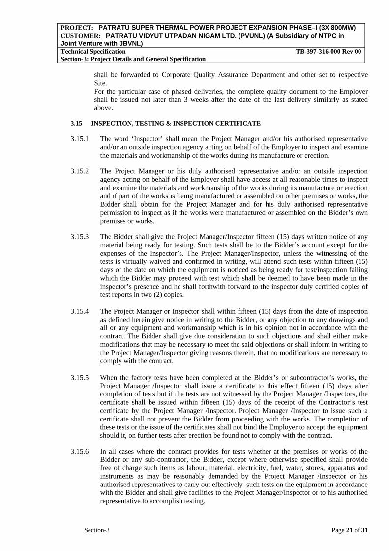
shall be forwarded to Corporate Quality Assurance Department and other set to respective Site.For the particular case of phased deliveries, the complete quality document to the Employer shall be issued not later than 3 weeks after the date of the last delivery similarly as stated above.
3.15 INSPECTION, TESTING & INSPECTION CERTIFICATE
3.15.1 The word ‘Inspector’ shall mean the Project Manager and/or his authorised representative and/or an outside inspection agency acting on behalf of the Employer to inspect and examine the materials and workmanship of the works during its manufacture or erection.
3.15.2 The Project Manager or his duly authorised representative and/or an outside inspection agency acting on behalf of the Employer shall have access at all reasonable times to inspect and examine the materials and workmanship of the works during its manufacture or erection and if part of the works is being manufactured or assembled on other premises or works, the Bidder shall obtain for the Project Manager and for his duly authorised representative permission to inspect as if the works were manufactured or assembled on the Bidder’s own premises or works.
3.15.3 The Bidder shall give the Project Manager/Inspector fifteen (15) days written notice of any material being ready for testing. Such tests shall be to the Bidder’s account except for the expenses of the Inspector’s. The Project Manager/Inspector, unless the witnessing of the tests is virtually waived and confirmed in writing, will attend such tests within fifteen (15) days of the date on which the equipment is noticed as being ready for test/inspection failing which the Bidder may proceed with test which shall be deemed to have been made in the inspector’s presence and he shall forthwith forward to the inspector duly certified copies of test reports in two (2) copies.
3.15.4 The Project Manager or Inspector shall within fifteen (15) days from the date of inspection as defined herein give notice in writing to the Bidder, or any objection to any drawings and all or any equipment and workmanship which is in his opinion not in accordance with the contract. The Bidder shall give due consideration to such objections and shall either make modifications that may be necessary to meet the said objections or shall inform in writing to the Project Manager/Inspector giving reasons therein, that no modifications are necessary to comply with the contract.
3.15.5 When the factory tests have been completed at the Bidder’s or subcontractor’s works, the Project Manager /Inspector shall issue a certificate to this effect fifteen (15) days after completion of tests but if the tests are not witnessed by the Project Manager /Inspectors, the certificate shall be issued within fifteen (15) days of the receipt of the Contractor’s test certificate by the Project Manager /Inspector. Project Manager /Inspector to issue such a certificate shall not prevent the Bidder from proceeding with the works. The completion of these tests or the issue of the certificates shall not bind the Employer to accept the equipment should it, on further tests after erection be found not to comply with the contract.
3.15.6 In all cases where the contract provides for tests whether at the premises or works of the Bidder or any sub-contractor, the Bidder, except where otherwise specified shall provide free of charge such items as labour, material, electricity, fuel, water, stores, apparatus and instruments as may be reasonably demanded by the Project Manager /Inspector or his authorised representatives to carry out effectively such tests on the equipment in accordance with the Bidder and shall give facilities to the Project Manager/Inspector or to his authorised representative to accomplish testing.
PROJECT: PATRATU SUPER THERMAL POWER PROJECT EXPANSION PHASE–I (3X 800MW)CUSTOMER: PATRATU VIDYUT UTPADAN NIGAM LTD. (PVUNL) (A Subsidiary of NTPC in Joint Venture with JBVNL)Technical Specification TB-397-316-000 Rev 00 Section-3: Project Details and General Specification
Section-3 Page 22 of 31
3.15.7 The inspection by Project Manager / Inspector and issue of Inspection Certificate thereon shall in no way limit the liabilities and responsibilities of the Contractor in respect of the agreed Quality Assurance Programme forming a part of the contract.
3.15.8 To facilitate advance planning of inspection in addition to giving inspection notice, the Bidder shall furnish quarterly inspection programme indicating schedule dates of inspection at Customer Hold Point and final inspection stages. Updated quarterly inspection plans will be made for each three consecutive months and shall be furnished before beginning of each calendar month.
3.15.9 All inspection, measuring and test equipments used by contractor shall be calibrated periodically depending on its use and criticality of the test/measurement to be done. The Bidder shall maintain all the relevant records of periodic calibration and instrument identification, and shall produce the same for inspection by NTPC. Wherever asked specifically, the contractor shall re-calibrate the measuring/test equipments in the presence of Project Manager / Inspector.
3.16 PACKAGING & TRANSPORTATION
All the equipments shall be suitably protected, coated, covered or boxed and crated to prevent damage or deterioration during transit, handling and storage at Site till the time of erection. While packing all the materials, the limitation from the point of view of the sizes of railway wagons available in India should be taken account of. The Bidder shall be responsible for any loss or damage during transportation, handling and storage due to improper packing. The Bidder shall ascertain the availability of Railway wagon sizes from the Indian Railways or any other agency concerned in India well before effecting despatch of equipment. Before despatch it shall be ensured that complete processing and manufacturing of the components is carried out at shop, only restricted by transport limitation, in order to ensure that site works like grinding, welding, cutting & preassembly to bare minimum. The Employer's Inspector shall have right to insist for completion of works in shops before despatch of materials for transportation.
3.17 CLAMPS AND CONNECTORS INCLUDING TERMINAL CONNECTORS
3.17.1 The material of clamps and connectors shall be Aluminium alloy casting conforming to designation A6 of IS:617 for connecting to equipment terminals and conductors of aluminium. In case the terminals are of copper, the same clamps/connectors shall be used with 2mm thick bimetallic liner.
3.17.2 The material of clamps and connectors shall be Galvanised mild steel for connecting to shield wire.
3.17.3 Bolts, nuts and plain washers shall be hot dip galvanised mild steel for sizes M12 and above. For sizes below M12, they shall be electro-galvanised mild steel. The spring washers shall be electro-galvanised mild steel.
3.17.4 All castings shall be free from blow holes, surface blisters, cracks and cavities. All sharp edges and corners shall be rounded off to meet specified corona and radio interference requirements.
3.17.5 They shall have same current rating as that of the connected equipment. All current carrying parts shall be at least 10 mm thick. The connectors shall be manufactured to have minimum contact resistance.

PROJECT: PATRATU SUPER THERMAL POWER PROJECT EXPANSION PHASE–I (3X 800MW)CUSTOMER: PATRATU VIDYUT UTPADAN NIGAM LTD. (PVUNL) (A Subsidiary of NTPC in Joint Venture with JBVNL)Technical Specification TB-397-316-000 Rev 00 Section-3: Project Details and General Specification
Section-3 Page 23 of 31
3.17.6 Flexible connectors, braids or laminated strips shall be made up of copper/aluminium.
3.17.7 Current rating and size of terminal/conductor for which connector is suitable shall be put on a suitable sticker on each component which should last atleast till erection time.
3.18 SPACERS
3.18.1 Spacers shall conform to IS: 10162. They shall be of non-magnetic material except nuts and bolts, which shall be of hot dip galvanised mild steel.
3.18.2 Spacers shall generally meet the requirements of clamps and connectors as specified above. Its design shall take care of fixing and removing during installation and maintenance.
3.18.3 In addition to the type tests as per IS: 10162, clamp slip test should have been conducted. In this test the sample shall be installed on test span of twin/quad bundle string at a tension of 44.2kN (4500 kg). One of the clamps when subjected to a longitudinal pull of 2.5kN (250 kg) parallel to the axis of conductor shall not slip, i.e. permanent displacement between conductor and clamp after test shall not exceed 1.0 mm. This test should have been performed on all other clamps of the sample.
3.19 BUSHINGS, HOLLOW COLUMN INSULATORS, SUPPORT INSULATORS, AND DISC INSULATORS
3.19.1 Bushings shall be manufactured and tested in accordance with IS: 2099 & IEC: 60137 while hollow column insulators shall be manufactured and tested in accordance with IEC62155/IS 5284. The support insulators shall be manufactured and tested as per IS: 2544/IEC 60168/IEC 60273. The insulators shall also conform to IEC 60815 as applicable having alternate long and short sheds. Support insulators/ bushings/ hollow column insulators shall be designed to have ample insulation, mechanical strength and rigidity for the conditions under which they will be used.
3.19.2 Porcelain used shall be homogenous, free from laminations, cavities and other flaws or imperfections that might affect the mechanical or dielectric quality and shall be thoroughly vitrified, tough and impervious to moisture.
3.19.3 Glazing of the porcelain shall be uniform brown in colour, free form blisters, burns and other similar defects.
3.19.4 The design of the insulator shall be such that stresses due to expansion and contraction in any part of the insulator shall be lead to deterioration. All ferrous parts shall be hot dip galvanised.
3.19.5 Post type insulators shall consist of a porcelain part permanently secured in metal base to be mounted on supporting structures. They shall be capable of being mounted upright. They shall be designed to withstand all shocks to which they may be subjected to during operation of the associated equipment.
3.19.6 Bushing porcelain shall be robust and capable of withstanding the internal pressures likely to occur in service. The design and location of clamps, the shape and the strength of the porcelain flange securing the bushing to the tank shall be such that there is no risk of fracture. All portions of the assembled porcelain enclosures and supports other than gaskets, which may in any way be exposed to the atmosphere shall be composed of completely non hygroscopic material such as metal or glazed porcelain.

PROJECT: PATRATU SUPER THERMAL POWER PROJECT EXPANSION PHASE–I (3X 800MW)CUSTOMER: PATRATU VIDYUT UTPADAN NIGAM LTD. (PVUNL) (A Subsidiary of NTPC in Joint Venture with JBVNL)Technical Specification TB-397-316-000 Rev 00 Section-3: Project Details and General Specification
Section-3 Page 24 of 31
3.19.7 All iron parts shall be hot dip galvanised and all joints shall be air tight. Surface of joints shall be trued, porcelain parts by grinding and metal parts by machining. Insulator/ bushing design shall be such as to ensure a uniform compressive pressure on the joints.
3.19.8 In accordance with the requirement stipulated elsewhere, bushing, hollow column insulators and support insulators shall conform to type tests and shall be subjected to routine tests and acceptance test/sample test in accordance with relevant standards.
3.20 CONTROL CABINETS, JUNCTION BOXES, TERMINAL BOXES & MARSHALLING BOXES FOR OUTDOOR EQUIPMENT.
3.20.1 All types of control cabinets, junction boxes, marshaling boxes, lighting panels, terminal boxes, operating mechanism boxes, Kiosks etc. shall generally conform to IS:5039, IS:8623 and IEC:60439 as applicable.
3.20.2 They shall be of Stainless steel or Aluminium. The thickness of Stainless steel shall be minimum 1 mm. The thickness of aluminium shall be minimum 3 mm and shall provide rigidity. Top of the boxes shall be sloped towards the rear of the box.
3.20.3 BAY MARSHALLING BOX
Bay Marshaling Box located at a convenient location to receive and distribute cables shall be provided as required. It shall meet all the requirements as specified for cabinets/boxes.
It shall have three separate distinct compartments for following purposes:
- To receive two incoming 415V, three phase, AC supplies controlled by 100A four pole MCBs with auto changeover provision, and to distribute five (5) three phase ac supplies controlled by 32A four pole MCBs. It shall also be provided with 63A, 3 phase 4 pin industrial grade receptacle with rotary switch.
- To receive three phase incoming from first compartment and to distribute ten (10) single phase ac supplies controlled by 16A two pole MCBs.
- 150 nos. terminal blocks in vertical formation for interlocking facility.
3.20.4 AUXILIARY SWITCH
The auxiliary switch shall conform of following type tests:
a) Electrical endurance test - A minimum of 1000 operations for 2A. D.C. with a time constant greater than or equal to 20 milliseconds with a subsequent examination of mV drop/ visual defects/ temperature rise test.
b) Mechanical endurance test - A minimum of 5000 operations with a subsequent checking of contact pressure test/ visual examination
c) Heat run test on contacts d) IR/HV test, etc.

PROJECT: PATRATU SUPER THERMAL POWER PROJECT EXPANSION PHASE–I (3X 800MW)CUSTOMER: PATRATU VIDYUT UTPADAN NIGAM LTD. (PVUNL) (A Subsidiary of NTPC in Joint Venture with JBVNL)Technical Specification TB-397-316-000 Rev 00 Section-3: Project Details and General Specification
Section-3 Page 25 of 31
3.21 CABLE GLANDS AND LUGS/FERRULES
3.21.1 Cable shall be terminated using double compression type cable glands. Testing requirements of Cable glands shall conform to BS:6121 and gland shall be of robust construction capable of clamping cable and cable armour (for armoured cables) firmly without injury to insulation. Cable glands shall be made of heavy duty brass machine finished and nickel chrome plated. Thickness of plating shall not be less than 10 micron. All washers and hardware shall also be made of brass with nickel chrome plating Rubber components shall be of neoprene or better synthetic material and of tested quality. Cable glands shall be suitable for the sizes of cable supplied/erected.
3.21.2 Cable lugs/ferrules for power cables shall be tinned copper solderless crimping type suitable for aluminium compacted conductor cables. Cable lugs and ferrules for control cables shall be tinned copper type. The cable lugs for control cables shall be provided with insulating sleeve and shall suit the type of terminals provided on the equipments. Cable lugs and ferrule shall conform to DIN standards.
3.22 CONDUITS, PIPES AND ACCESSORIES
3.22.1 The bidder shall supply and install all rigid conduits, mild steel pipes, flexible conduits, hume pipes, etc. including all necessary sundry materials, such as tees, elbows, check nuts, bushing reduces, enlargers, wooden plugs, coupling caps, nipples, gland sealing fittings, pull boxes, etc.
3.22.2 The size of the conduit/pipe shall be selected to limit the fill to a maximum of 40%. All conduits/pipes shall have their ends closed by caps until cables are pulled. After cables are pulled, the ends of conduits/pipes shall be sealed in an approved manner to prevent damage to threaded portions and en- trance of moisture and foreign materials.
3.22.3 PVC conduits shall be of high impact, heavy gauge (at least class 2) conduit conforming to BS-4607.
3.22.4 The outer surface of the steel conduits shall be coated with hot-dip zinc and chromate conversion coatings. The inner surface shall have silicone epoxy ester coating for easy cable pulling. Mild steel pipes shall be hot-dip galvanized. All rigid conduits/pipes shall be of a reputed make.
3.22.5 The hume pipes and accessories shall be of reinforced concrete conforming to class NP2 of IS-458. All tests on hume pipes shall be conducted as per IS-458.
3.22.6 Flexible conduits shall be of heat-resistant lead coated steel, water-leak, fire and rust proof.
3.23 MOTORS
The voltage level for motors shall be as follows:
a) Upto 0.2 KW : Single phase 240V AC / 3 phase 415V AC b) Above 0.2 KW and upto 200 KW : 3 phase, 415V AC c) Above 200 KW and upto 1500 KW : 3 phase, 3.3 kV AC d) Above 1500 KW : 11 kV
The bidder may adopt 415V/3.3 KV for the drives rated in the range of 160-210 KW.
PROJECT: PATRATU SUPER THERMAL POWER PROJECT EXPANSION PHASE–I (3X 800MW)CUSTOMER: PATRATU VIDYUT UTPADAN NIGAM LTD. (PVUNL) (A Subsidiary of NTPC in Joint Venture with JBVNL)Technical Specification TB-397-316-000 Rev 00 Section-3: Project Details and General Specification
Section-3 Page 26 of 31
The voltage rating of the drives indicated above is for basic guideline.
3.23.1 All motors shall conform to IEC-60034-5 / IS Standard and with principal dimensions in accordance with IEC 60072-1 (1991), IEC 60072-2 (1990) and IEC 60072-3 (1994).
3.23.2 All equipment shall be suitable for rated frequency of 50 Hz with a variation of +3% & -5%, and 10% combined variation of voltage and frequency unless specifically brought out in the specification
3.23.3 Paint shade shall be as per RAL 5012 (Blue) for indoor and outdoor equipment.
3.23.4 Degree of Protection
Degree of protection for various enclosures as per IEC60034-05 shall be as follows:
Indoor motors - IP 54 Outdoor motors - IP 55 Cable box-indoor area - IP 54 Cable box-Outdoor area - IP 55
3.23.5 Type:
AC Motors:
a) Squirrel cage induction motor suitable for direct-on-line starting. b) Continuous duty LT motors upto 200 KW Output rating (at 50 deg.C ambient
temperature), shall be Premium Efficiency class-IE3, conforming to IS 12615, or IEC:60034-30.
c) Crane duty motors shall be squirrel cage Induction motor as per the requirement. d) Motor operating through variable frequency drives shall be suitable for inverter
duty. Also these motors shall comply the requirements stipulated in IEC: 60034-18-41 and IEC: 60034-18-42 as applicable.
DC Motors Shunt wound
3.24 AUXILIARY SWITCH
The auxiliary switch shall conform of following type tests: a) Electrical endurance test - A minimum of 1000 operations for 2A. D.C. with a time constant
greater than or equal to 20 milliseconds with a subsequent examination of mV drop/ visual defects/ temperature rise test.
b) Mechanical endurance test - A minimum of 5000 operations with a subsequent checking of contact pressure test/ visual examination
c) Heat run test on contacts d) IR/HV test, etc.
3.25 LAMPS AND SOCKETS
3.25.1 Lamps: All incandescent lamps shall use a socket base as per IS-1258, except in the case of signal lamps.
3.25.2 Sockets

PROJECT: PATRATU SUPER THERMAL POWER PROJECT EXPANSION PHASE–I (3X 800MW)CUSTOMER: PATRATU VIDYUT UTPADAN NIGAM LTD. (PVUNL) (A Subsidiary of NTPC in Joint Venture with JBVNL)Technical Specification TB-397-316-000 Rev 00 Section-3: Project Details and General Specification
Section-3 Page 27 of 31
All sockets (convenience outlets) shall be suitable to accept both 5 Amp & 15 Amp pin round Standard Indian plugs. They shall be switched sockets with shutters.
3.25.3 Hand Lamp:
A 240 Volts, single Phase, 50 Hz AC plug point shall be provided in the interior of each cubicle with ON-OFF Switch for connection of hand lamps.
3.26 SWITCHES & FUSES:
Each control panel shall be provided with necessary arrangements for receiving, distributing, isolating and fusing of DC and AC supplies for various control, signaling, lighting and space heater circuits. The incoming and sub-circuits shall be separately provided with switch-fuse units. Selection of the main and sub-circuit fuse ratings shall be such as to ensure selective clearance of sub-circuit faults. Potential circuits for relaying and metering shall be protected by HRC fuses.
All fuses shall be of HRC cartridge type conforming to IS 9228 mounted on plug-in type fuse bases. Miniature circuit breakers with thermal Protection and alarm contacts will also be accepted. All accessible live connection to fuse bases shall be adequately shrouded. Fuses shall have operation indicators for indicating blown fuse condition. Fuse carrier base shall have imprints of the fuse rating and voltage.
All control switches shall be of rotary type. Toggle/piano switches shall not be accepted.
3.27 TYPE, ROUTINE & ACCEPTANCE TESTS:
3.10.1 TYPE TEST REQUIREMENTS FOR EQUIPMENTS OTHER THAN GIS
a) All equipments to be supplied shall be of type tested design. During detail engineering, the bidder shall submit for Owner’s approval the reports of all the type tests as listed in this specification and carried out not earlier than ten years prior to the date of techno-commercial bid opening (03-March-2017). These reports should be for the test conducted on the equipment similar to those proposed to be supplied under this contract and the test(s) should have been either conducted at an independent laboratory or should have been witnessed by a Client.
b) However if contractor is not able to submit report of the type test(s) conducted not earlier than ten years prior to the date of techno-commercial bid opening (03-March-2017)., or in the case of type test report(s) are not found to be meeting the specification requirements, the bidder shall conduct all such tests under this contract at no additional cost to the owner either at third party lab or in presence of client/ owners representative and submit the reports for approval.
c) All acceptance and routine tests as per the specification and relevant standards shall be carried out. Charges for these shall be deemed to be included in the equipment price.
3.28 CORONA AND RIV TESTS AND SEISMIC WITHSTAND TEST:
a) The corona and RIV tests shall confirm to the requirements as per Annexure A. b) The seismic withstand test for shall conform to requirements as per Annexure B.

PROJECT: PATRATU SUPER THERMAL POWER PROJECT EXPANSION PHASE–I (3X 800MW)CUSTOMER: PATRATU VIDYUT UTPADAN NIGAM LTD. (PVUNL) (A Subsidiary of NTPC in Joint Venture with JBVNL)Technical Specification TB-397-316-000 Rev 00 Section-3: Project Details and General Specification
Section-3 Page 28 of 31
3.29 Enclosures:
1. ANNEXURE- A - CORONA AND RADIO INTERFERENCE VOLTAGE (RIV) TEST 2. ANNEXURE- B - SEISMIC WITHSTAND TEST 3. ANNEXURE- I – MQP (NTPC format) 4. ANNEXURE- II – QUALITY ASSURANCE FOR SWITCHYARD

PROJECT: PATRATU SUPER THERMAL POWER PROJECT EXPANSION PHASE–I (3X 800MW)CUSTOMER: PATRATU VIDYUT UTPADAN NIGAM LTD. (PVUNL) (A Subsidiary of NTPC in Joint Venture with JBVNL)Technical Specification TB-397-316-000 Rev 00 Section-3: Project Details and General Specification
Section-3 Page 29 of 31
ANNEXURE – A
CORONA AND RADIO INTERFERENCE VOLTAGE (RIV) TEST
1.0 General
Unless otherwise stipulated, all equipment together with its associated connectors where applicable shall be tested for external corona both by observing the voltage level for the extinction of visible corona under falling power frequency voltage and measurement of radio interference voltage ( RIV).
2.0 Test Levels
The test voltage levels for measurement of external RIV and for corona extinction voltage are listed under the relevant clauses of the specification.
3.0 Test Methods for RIV (400kV):
3.1 RIV tests shall be made according to measuring circuit as per International Special committee on Radio Interference ( CISPR) Publication 16 -1 ( 1993) Part – I. The measuring circuit shall preferably be tuned to frequency with 10 % of 0.5 MHz but other frequencies in the range of 0.5 MHZ to 2 MHz may be used, the measuring frequency being recorded. The result shall be in microvolts.
3.2 Alternatively, RIV tests shall be in accordance with NEMA standard Publication No. 107 – 1964 except otherwise noted herein.
3.3 In measurement of RIV temporary additional external corona shielding may be provided. In measurement of RIV only standard fittings of identical type supplied with the equipment and a simulation of the connections as used in the actual installation will be permitted in the vicinity within 3.5 meters of terminals.
3.4 Ambient noise shall be measured before and after each series of tests to ensure that there is no variation in ambient noise level. If variation is present, the lowest ambient noise level will form basis for the measurements. RIV levels shall be measured at increasing and decreasing voltages of 85%, 100%, 115% and 130% for the specified RIV test voltage for all equipment unless otherwise specified. The specified RIV test voltage for 765kV, 400kV, 220kV & 132kV is listed in the detailed specification together with maximum permissible RIV level in microvolts.
3.5 The metering instruments shall be as per CISPR recommendations or equivalent device so long as it has been used by other testing authorities.
3.6 The RIV measurement may be made with a noise meter. A calibration procedure of the frequency to which noise meter shall be tuned shall establish the ratio of voltage at the high voltage terminal to the voltage read by the noise meter.
4.0 Test Methods for visible Corona (400kV AIS only)
The purpose of this test is to determine the corona extinction voltage of the apparatus, connectors etc. The test shall be carried out in the same manner as RIV test described above with the exception that RIV measurements are not required during test and a search technique shall be used near the onset and extinction voltage, when the test voltage is raised and lowered to determine their precise values. The test voltage shall be raised to 130 % of RIV test voltage

PROJECT: PATRATU SUPER THERMAL POWER PROJECT EXPANSION PHASE–I (3X 800MW)CUSTOMER: PATRATU VIDYUT UTPADAN NIGAM LTD. (PVUNL) (A Subsidiary of NTPC in Joint Venture with JBVNL)Technical Specification TB-397-316-000 Rev 00 Section-3: Project Details and General Specification
Section-3 Page 30 of 31
ANNEXURE – A
and maintained there for five minutes. In case corona inception does not take place at 130 %, the voltage level shall be raised till inception of corona or rated voltage whichever is lower. The voltage will then be decreased slowly until all visible corona disappears. The test procedure shall be repeated at least 4 times with corona inception and extinction voltage recorded each time. The corona extinction voltage for purposes of determining compliance with the specification shall be the lowest of the four values at which the visible corona (negative or positive polarity) disappears.
PROJECT: PATRATU SUPER THERMAL POWER PROJECT EXPANSION PHASE–I (3X 800MW)CUSTOMER: PATRATU VIDYUT UTPADAN NIGAM LTD. (PVUNL) (A Subsidiary of NTPC in Joint Venture with JBVNL)Technical Specification TB-397-316-000 Rev 00 Section-3: Project Details and General Specification
Section-3 Page 31 of 31
ANNEXURE – B
SEISMIC WITHSTAND TEST (400kV AIS only)
a.) The seismic withstand test on the complete equipment (except BPI) shall be carried out along with supporting structure.
b.) The supplier shall arrange to transport the structure from his purchaser’s premises / owner’s sites for purpose of seismic withstand test only.
c.) The seismic level specified shall be applied at the base of the structure. The accelerometers shall be provided at the terminal pad of the equipment and at any other point as agreed by the owner. The seismic test shall be carried out in all possible combinations of the equipment. The seismic test procedure shall be furnished for approval of the purchaser.


400kV GIS at Patratu Super Thermal Power Project Expansion Phase –I (3X800 MW).
OPGW & Its Accessories – TL Diversion Doc. No. : TB-397-510-008 Rev 00
Page 8 of 8
SECTION-4
CHECKLIST FOR TECHNICAL EVALUATION Along with the Technical Bids of the offers, the Bidder should submit this checklist confirming the inclusion of the enclosures as listed below. (Shall tick as )
Sr No
Documents to be enclosed Bidder to check & confirm
1. Copy of Unpriced BOQ as enclosed in the Technical Specification to confirm that bidder has quoted in the same format
2. Schedule of Technical Deviation format duly signed
3. Technical parameters as per Section-2 of Technical Specification duly signed.
NOTE:- If the Bidder fails to submit any of the documents as asked in the above check list, their bid is likely to be rejected / not evaluated. The above checklist is verified for:- NIT Ref No. : Name of Equipment : Name of Project : Name of Bidder : Signed with Seal of Bidder Date ………………..